32
UNLOADING, STORAGE, ERECTION, INSTALLATION & MAINTENANCE MANUAL PANTOGRAPH ISOLATOR (TYPE: RP 123kV)

UNLOADING, STORAGE, ERECTION,
INSTALLATION & MAINTENANCE MANUAL
PANTOGRAPH ISOLATOR
(TYPE: RP 123kV)

Disconnectors are remarkable pieces of equipment.
They can stay in the same position for years before they
have to switch. But, then at the critical movement they
have to work perfectly. No matter what the conditions
are, whether they are in the freezing cold or in the
extreme heat.

INDEX
1.0. PREAMBLE 1
2.0. GENERAL DESCRIPTION OF THE DISCONNECTOR 1
SECTION-A: UNLOADING AND STORAGE INSTRUCTIONS
3.0. UNLOADING 2
3.1. STORAGE 2
3.2. LONG TERM STORAGE INSTRUCTIONS 3
SECTION-B: CONSTRUCTION
4.0. SCOPE OF SUPPLY 6
5.0. SUPPORT STRUCTURE 6
6.0. SUPPORT INSULATOR & OPERATING INSULATOR STACK 7
7.0. TOP HAMPER ASSEMBLY 7
8.0. FIXED CONTACT ASSEMBLY 9
9.0. OPERATING DRIVE MECHANISM 10
10.0. DOWN OPERATING PIPE 10
SECTION-C: INSTALLATION & SETTING INSTRUCTION
11.0. ERECTION SEQUENCE 12
12.0. ERECTION OF STRUCTURE 12
13.0. ERECTION OF INSULATORS 12
14.0. ERECTION OF TOP HAMPERS 14
15.0. ERECTION OF FIXED CONTACT 15
16.0. ERECTION OF DRIVE BOX 16
17.0. ERECTION OF TANDEM PIPE 17
18.0. ERECTION OF DOWN OPERATING PIPE 24

SECTION-D: COMMISIONING AND MAINTENANCE
19.0. COMMISIONING OF DISCONNECTOR 25
20.0. MAINTENANCE 25
21.0. TOOLS AND TACKLES 26
22.0. CLEANING 26
23.0. INSPECTION CHECKS 27
24.0. RECOMMENDED SPARES 27

1.0. PREAMBLE:
This manual pertains to Pantograph disconnectors of voltage rating 123kV. The
disconnector described in this publication is designed, manufactured and tested with care and
will give satisfactory service if it is installed, operated and maintained in accordance with the
instructions, by fully skilled personnel duly authorized to carry out this work.
Efforts are constantly being made to improve design and manufacture. The equipment
supplied may differ in detail from the data given in this publication
.
2.0 GENERAL DESCRIPTION OF THE DISCONNECTOR:
• Disconnectors are primarily off-load mechanical switching device used to isolate
equipments and lines in electrical network. They are able to make or break the
magnetizing current and line charging current of 0.7Amps at 0.15 power factors.
• Pantograph Isolators are designed for independent single pole operation or three pole
mechanical ganged operation.
• Pantograph Isolators are supplied asbreak down components and are assembled at site.
The relevant standards for these are IS:9921 and IEC:129-1984. Insulators, which
constitute a part, conforms to IS:2544 and IEC:273.
• The relevant standards for Disconnectors are IEC: 62271-102 and 62271-1
(Supersedes IEC: 60694) and IS: 9921 and for insulators IEC:
60273 and 60168 and IS: 2544.
SECTION-A
UNLOADING AND STROAGE INSTRUCTIONS
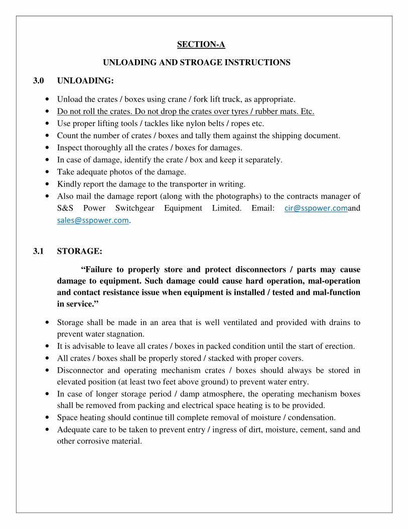
3.0 UNLOADING:
• Unload the crates / boxes using crane / fork lift truck, as appropriate.
• Do not roll the crates. Do not drop the crates over tyres / rubber mats. Etc.
• Use proper lifting tools / tackles like nylon belts / ropes etc.
• Count the number of crates / boxes and tally them against the shipping document.
• Inspect thoroughly all the crates / boxes for damages.
• In case of damage, identify the crate / box and keep it separately.
• Take adequate photos of the damage.
• Kindly report the damage to the transporter in writing.
• Also mail the damage report (along with the photographs) to the contracts manager of
S&S Power Switchgear Equipment Limited. Email: [email protected]
3.1 STORAGE:
“Failure to properly store and protect disconnectors / parts may cause
damage to equipment. Such damage could cause hard operation, mal-operation
and contact resistance issue when equipment is installed / tested and mal-function
in service.”
• Storage shall be made in an area that is well ventilated and provided with drains to
prevent water stagnation.
• It is advisable to leave all crates / boxes in packed condition until the start of erection.
• All crates / boxes shall be properly stored / stacked with proper covers.
• Disconnector and operating mechanism crates / boxes should always be stored in
elevated position (at least two feet above ground) to prevent water entry.
• In case of longer storage period / damp atmosphere, the operating mechanism boxes
shall be removed from packing and electrical space heating is to be provided.
• Space heating should continue till complete removal of moisture / condensation.
• Adequate care to be taken to prevent entry / ingress of dirt, moisture, cement, sand and
other corrosive material.
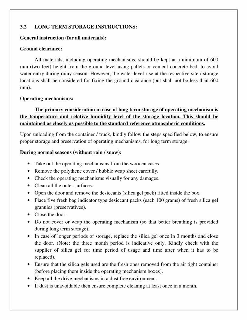
3.2 LONG TERM STORAGE INSTRUCTIONS:
General instruction (for all materials):
Ground clearance:
All materials, including operating mechanisms, should be kept at a minimum of 600
mm (two feet) height from the ground level using pallets or cement concrete bed, to avoid
water entry during rainy season. However, the water level rise at the respective site / storage
locations shall be considered for fixing the ground clearance (but shall not be less than 600
mm).
Operating mechanisms:
The primary consideration in case of long term storage of operating mechanism is
the temperature and relative humidity level of the storage location. This should be
maintained as closely as possible to the standard reference atmospheric conditions.
Upon unloading from the container / truck, kindly follow the steps specified below, to ensure
proper storage and preservation of operating mechanisms, for long term storage:
During normal seasons (without rain / snow):
• Take out the operating mechanisms from the wooden cases.
• Remove the polythene cover / bubble wrap sheet carefully.
• Check the operating mechanisms visually for any damages.
• Clean all the outer surfaces.
• Open the door and remove the desiccants (silica gel pack) fitted inside the box.
• Place five fresh bag indicator type desiccant packs (each 100 grams) of fresh silica gel
granules (preservatives).
• Close the door.
• Do not cover or wrap the operating mechanism (so that better breathing is provided
during long term storage).
• In case of longer periods of storage, replace the silica gel once in 3 months and close
the door. (Note: the three month period is indicative only. Kindly check with the
supplier of silica gel for time period of usage and time after when it has to be
replaced).
• Ensure that the silica gels used are the fresh ones removed from the air tight container
(before placing them inside the operating mechanism boxes).
• Keep all the drive mechanisms in a dust free environment.
• If dust is unavoidable then ensure complete cleaning at least once in a month.

• In addition carry out periodical checks for any abnormal dust accumulation and clean
accordingly.
• Ensure that the entire storage area is temperature controlled (to ensure better storage
and condition of the equipment).
• The optimum temperature is 20 deg c and relative humidity is 45% (values to be
checked using combined humidity and temperature indicators placed throughout the
warehouse / storage area and should be visible for close monitoring).
During monsoon seasons (with rain / snow):
• All points given above shall be followed.
• In addition, during rainy season, anti condensation heaters to be kept “on” and suitable
electrical protection to trip the electrical circuit to be provided in case of any short
circuit.
• Foam adhesive backed strip with volatile corrosion inhibitors also to be paste along the
inner surfaces of the operating mechanism in place of silica gels.
• Inspect all operating mechanism boxes for integrity of the painted surfaces once in a
month.
Other contacts and steel materials:
• Clean all the contact surfaces thoroughly with a lint-free cloth.
• Protect all contact surfaces with a thin layer of petroleum gel.
• Cover all contacts and Aluminium arms with polythene sheets / covers.
• Ensure that the inside surfaces of the polythene coverings are pasted with foam based
adhesive strip.
• Provide volatile corrosion inhibitors sheets and paste them along the inner surfaces.
• Kindly repeat the above steps once in every three months.
Galvanized steel items:
These are to be wrapped / covered with waterproof / dust proof covering and sufficient
bags of silica gels to be placed in various places inside the covering. Once in 3 months all
materials to be cleaned and replaced with silica gel bags.

OVERALL ASSEMBLY
FIXED
CONTACT TOP
HAMPER
OPERATING
INSULATOR
SUPPORT
INSULATOR
BASE
OPERATING
MECHANISM
TORQUE
BEARING

SECTION – B
CONSTRUCTION
4.0. SCOPE OF SUPPLY
Our 123kV pantograph Isolator comprises the following:
4.1 Support structure (optional)
4.2 Support insulator and operating insulator
4.3 Top hamper assembly
4.4 Operating mechanism
4.5 Down operating pipe
4.6 Fixed contact assembly
5.0. Support Structure
Support structures are made out of MS tube/or angular frame as required by
customer site with the arrangement to fix over the foundation and to fix operating
mechanism box for main & earth and to fix earth switch assembly.
FIGURE A
TORQUE
BEARING FIXING
DRIVE BOX FIXING

6.0. Support Insulator / Operating Insulator
• Support Insulator are selected to suit basic insulation level, minimum creepage and
minimum bending load to suit customer and design requirement.
• Operating rod insulator are selected to suit the basic insulation level, minimum
creepage and minimum torsion load to suit customer and design requirement.
7.0. Top Hamper Assembly
Top hamper assembly consist of Upper arm and Lower arm sections. The upper
arm is made out of Aluminium tube where as the lower arm is constructed with
specially extruded Aluminium channel. The Upper arm fourpoint contact is made out
of electrolytic grade copper and silver plated for transferring the supply from the top
bus to the lower bus section though current transfer rotating contacts fixed on the
lower arm ends when the pantograph is in closed position. The MS frame work offers
the necessary support for the scissors assembly and also for the aluminium/copper bus
bar and also designed to minimize the corona discharge. The scissor’s operation is
achieved through the link which is in turn is actuated by the rotation of the drive lever.
The 95° semi-circular rotation in achieved with the help of the rotation rod insulator.
Toggle stopper limits the movements of drive lever both at the open and closed
position.

TOP HAMPER ASSEMBLY
FIXED CONTACT
MAIN FRAME
MECHANICAL
STOPPER
UPPER ARMS
LOWER ARMS

8.0. Fixed Contact
The design of trapeze contact arrangement will vary depending upon the top bus
(Conductor or tube) The trapeze contact is hung from top bus conductor made out of
silver plated copper contact tube. The copper fixed contact is suitably placed so as to
position itself on the 4 point contact. Due to temperature variation it the bus contacts
or elongates the fixed contact will simultaneously det raised/lowered. Even then it will
confine itself within the contact zone as shown in sketch. The excess length of
aluminium dropper rod can be cut.
Fixed Contact
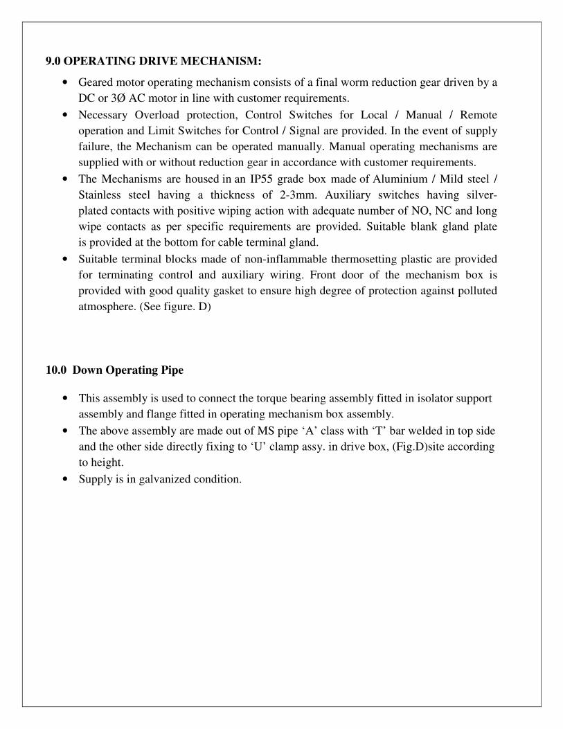
9.0 OPERATING DRIVE MECHANISM:
• Geared motor operating mechanism consists of a final worm reduction gear driven by a
DC or 3Ø AC motor in line with customer requirements.
• Necessary Overload protection, Control Switches for Local / Manual / Remote
operation and Limit Switches for Control / Signal are provided. In the event of supply
failure, the Mechanism can be operated manually. Manual operating mechanisms are
supplied with or without reduction gear in accordance with customer requirements.
• The Mechanisms are housed in an IP55 grade box made of Aluminium / Mild steel /
Stainless steel having a thickness of 2-3mm. Auxiliary switches having silver-
plated contacts with positive wiping action with adequate number of NO, NC and long
wipe contacts as per specific requirements are provided. Suitable blank gland plate
is provided at the bottom for cable terminal gland.
• Suitable terminal blocks made of non-inflammable thermosetting plastic are provided
for terminating control and auxiliary wiring. Front door of the mechanism box is
provided with good quality gasket to ensure high degree of protection against polluted
atmosphere. (See figure. D)
10.0 Down Operating Pipe
• This assembly is used to connect the torque bearing assembly fitted in isolator support
assembly and flange fitted in operating mechanism box assembly.
• The above assembly are made out of MS pipe ‘A’ class with ‘T’ bar welded in top side
and the other side directly fixing to ‘U’ clamp assy. in drive box, (Fig.D)site according
to height.
• Supply is in galvanized condition.

FIGURE – D
OPERATING MECHANISM
FIGURE – E
DOWN OPERATING PIPE

SECTION-C
INSTALLATION & SETTING INSTRUCTION
11.011.011.011.0. . . . ERECTION SEQUENCE:
- SUPPORT STRUCTURE
- INSULATORS
- TOP HAMPER ASSEMBLY
- FIXED CONTACT ASSEMBLY
- OPERATING DRIVE BOX
- DOWN OPERATING PIPE
12.0SUPPORT STRUCTURE
• Check for substation foundation plan, as the centre line of foundation is shifted by
130mm from the line contact to the centre line of the top.
• Ascertain the orientation of pantograph in relation with the location of operating
mechanism.
• Lift the structure assembly and fix it over the plinth. (without damaging the
foundation bolts)
• Assemble washer, spring washer and nut in all foundation bolts.
• Check for level at the top structure in both directions by using spirit levels. If
required give shims below the base plate of structure for levelling once levelled
tighten the nuts.
13.0. ERECTION OF INSULATOR
• Identify the insulator by usingGA drawing.
• Keep the insulators fixing hardware’s ready.
• Lift the insulator stack by using proper hook and place it over the support structure.
• Without removing the hook align the holes and fix all bolts.
• Remove the hook and check for level of top surface of insulator by spirit level/plumb.
• It necessary add shims below the bottom flange of the insulator.
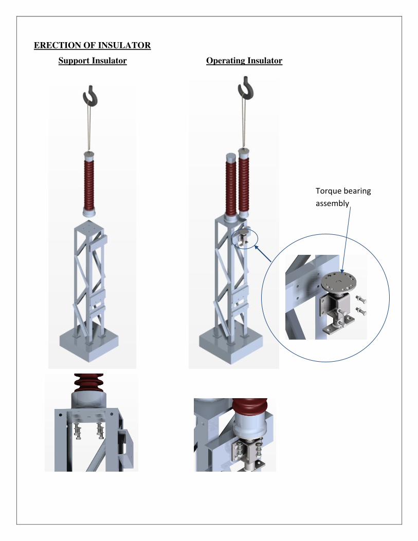
ERECTION OF INSULATOR
Support Insulator Operating Insulator
Torque bearing
assembly
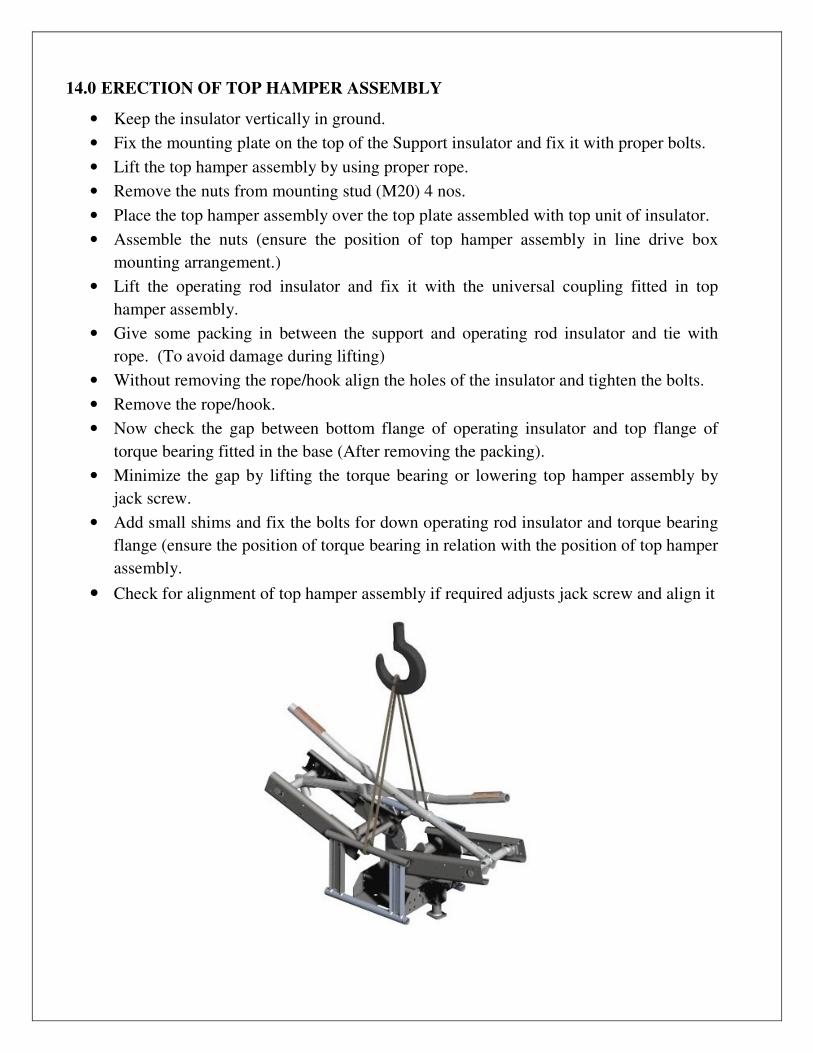
14.0 ERECTION OF TOP HAMPER ASSEMBLY
• Keep the insulator vertically in ground.
• Fix the mounting plate on the top of the Support insulator and fix it with proper bolts.
• Lift the top hamper assembly by using proper rope.
• Remove the nuts from mounting stud (M20) 4 nos.
• Place the top hamper assembly over the top plate assembled with top unit of insulator.
• Assemble the nuts (ensure the position of top hamper assembly in line drive box
mounting arrangement.)
• Lift the operating rod insulator and fix it with the universal coupling fitted in top
hamper assembly.
• Give some packing in between the support and operating rod insulator and tie with
rope. (To avoid damage during lifting)
• Without removing the rope/hook align the holes of the insulator and tighten the bolts.
• Remove the rope/hook.
• Now check the gap between bottom flange of operating insulator and top flange of
torque bearing fitted in the base (After removing the packing).
• Minimize the gap by lifting the torque bearing or lowering top hamper assembly by
jack screw.
• Add small shims and fix the bolts for down operating rod insulator and torque bearing
flange (ensure the position of torque bearing in relation with the position of top hamper
assembly.
• Check for alignment of top hamper assembly if required adjusts jack screw and align it
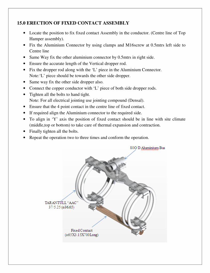
15.0 ERECTION OF FIXED CONTACT ASSEMBLY
• Locate the position to fix fixed contact Assembly in the conductor. (Centre line of Top
Hamper assembly).
• Fix the Aluminium Connector by using clamps and M16screw at 0.5mtrs left side to
Centre line
• Same Way fix the other aluminium connector by 0.5mtrs in right side.
• Ensure the accurate length of the Vertical dropper rod.
• Fix the dropper rod along with the ‘L’ piece in the Aluminium Connector.
Note:‘L’ piece should be towards the other side dropper.
• Same way fix the other side dropper also.
• Connect the copper conductor with ‘L’ piece of both side dropper rods.
• Tighten all the bolts to hand tight.
Note: For all electrical jointing use jointing compound (Densal).
• Ensure that the 4 point contact in the centre line of fixed contact.
• If required align the Aluminium connector to the required side.
• To align in ‘Y’ axis the position of fixed contact should be in line with site climate
(middle,top or bottom) to take care of thermal expansion and contraction.
• Finally tighten all the bolts.
• Repeat the operation two to three times and conform the operation.
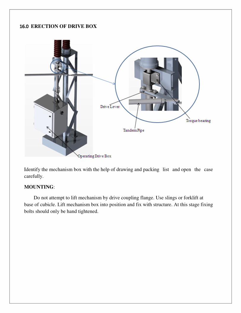
16.016.016.016.0 ERECTION OF DRIVE BOX
Identify the mechanism box with the help of drawing and packing list and open the case
carefully.
MOUNTING:
Do not attempt to lift mechanism by drive coupling flange. Use slings or forklift at
base of cubicle. Lift mechanism box into position and fix with structure. At this stage fixing
bolts should only be hand tightened.

17.0 ERECTION OF TANDEM FOR 3-POLES
� Remove the connecting pin from the lever and keep it separately.
� Keep the Drive end Disconnector in closed position
� Keep the Second pole in closed position. Connect the tandem pipe (Phase coupling
pipe). If required extend or shorten by adjusting the screw rod.
� Operate the Disconnector manually and ensure if opens and close properly. If not,
then adjust the tandem pipe length. Ensure all split pins are secured properly
Headed Pin
Brass Washer
Nylon Washer
Split Pin

CONNECTING DISCONNECTOR:
• Check for centre line and vertical line between torque bearing flange and drive flange
with a plumb.
• Fix the tee bar end of the down operating pipe to the universal yoke and fix the
assembly to the provision available on the drive end base (See figure. M).
• Now fix the other end of down operating pipe to the universal yoke and fix the
assembly to drive box flange using the principle of vernierhole alignment (Only two
holes will be aligned).
• Tighten all bolts.
• Operate the pole manually and ensure open/close label is in proper position.
ADJUSTMENT:
A. MANUAL
By using emergency handle, operate the coupled disconnector and observe whether it is
OPENS or CLOSES fully at each end of its operating cycle. (Ensure minimum 10mm gap
between pad lock brackets.) If the disconnector does not CLOSE fully remove clamping
bolts which is bolted on the operating mechanism flange and turn mechanism slightly
towards OPEN and re-tighten the bolts with the help of the Vernier holes provided.
Proceed with disconnector closing. Repeat until satisfactory operation is obtained.
B. ELECTRICAL
Make electrical connections strictly according to the contract diagram of connections of
incoming supply. Do not attempt to operate the Disconnector under power at this stage.
When selector switch is fitted, set it to LOCAL.
When Motor is fitted, manually set Mechanism to mid Position and: -
• Operate Control Switch and at the same time observe whether the mechanism rotates
towards the selected position.
• If it rotates in opposite direction to that selected, stop motor immediately, by switching
off power supply using Emergency push button switch.
• Reverse the connection of motor supply.
ELECTRICAL OPERATING EQUIPMENT:
A hinged panel on the left hand or right hand side of the cabinet carries the electrical
control, for operation of the mechanism, which is accessible immediately after the cabinet
outer door is opened.

PANEL DOOR COMPONENTS:
LOCAL / REMOTE / MANUAL SELECTOR SWITCH
This selector switch is provided to select the position according to the requirement. When
the selector switch is set to local, operation of the mechanism will be governed by the
controls in the cabinet. Setting the selector switch to remote transfers controls of the
mechanism to remove control point.
OPEN AND CLOSE SWITCH
Incase of individual pole drives, the master control cabinet will have push buttons / selector
switch for opening / closing also. The control switch determines the direction of travel of
the disconnector. When a cycle is initiated by switching to the appropriate position, the
disconnector will open or close. Once the mechanism receives a signal from the push
button/ selector switch, the mechanism will commence the operation and will not respond
to further signals until it has completed its operation. An indicator is provided outside the
top sheet of the cabinet (below the output shaft) to show the disconnector is
OPEN or CLOSE.
HEATER AND THERMOSTAT (OPTIONAL)
An anti-condensation heater is fitted in the cabinet. A switch is mounted on the front of the
control panel for the control of the heater through a thermostat. It should be switched on as
and when required to ensure that appropriate temperature inside the cabinet is maintained.
The heated air leaves the cabinet by way of a breather.
OPEN AND CLOSE CONTACTORS
These contactors are mounted in the rear of the panel door. They directly control the
reversing operation of the motor. Further contacts are used for electrically interlocking the
contactors, providing circuit across the ‘OPEN’ and ‘CLOSE’ Push Buttons / Cam Switch.
AUXILLARY SWITCHES
Auxiliary switch are mounted in the rear side of the cabinet connected to gear shaft through
cam and operating lever. It consist of silver plated contacts with a positive wiping action,
which provides low current signal to the control circuit.
TERMINAL BLOCKS
Terminal Blocks are designed for use with 1.5 / 2.5 Sqmm cable. Rated Miniature circuit
Breaker / Fuse is mounted in the panel door. The current ratings of Fuse/MCB -
links are shown on the schematic diagram.
FOR CLOSING THE DISCONNECTOR
Set the selector switch to local execution as required and then operate the cam switch
for closing, there by causing the closing contactor (CC) to pick up. The hold on contact of closing contactor (CC) will now be closed there by retaining the supply after the cam switch is released.
After completion of closing cycle, when the disconnector operate for opening, the opening
contactor (OC) will pickup. The hold on contact of opening contactor (OC) will now be
closed there by retaining the supply after the cam switch is released. Ensure motor direction
is towards closing. Otherwise change the phase sequence of motor in terminal box. The
disconnector will start to close. At the end of the closing operation limit switch for
closing (LSC) will open, de-energizing the closing contactor (CC). The circuit is now de-
energized and the closing operation is completed.
Kindly note, to prevent malfunction, contact (CC) of the closing contactor will isolate the
opening circuit, once contactor (CC) is energized.
FOR OPENING THE DISCONNECTOR
A Similar sequence of operation will be executed by operating the cam switch in the other
direction.
OPERATION OF BOLT COIL (MOTOR / MANUAL)
CONDITION – 1
MAIN DISCONNECTOR CLOSED AND EARTH SWITCH OPEN
LMR (Local Manual Remote) switch in local or remote position.
• The plunger is in protruded condition (coil de-energized).
• The cap fixed to the plunger blocks the insertion of the manual handle (there by
preventing manual operation).
• At this condition there will not be supply to push button switch. (MPB).
CONDITION –2.
MAIN DISCONNECTOR OPENED
LMR switch in manual position.
• Now the push button switch (MPB) will get supply.
• When the MPB switch is pressed, the supply will go to bolt coil and pulls the plunger
downwards.
• The plunger in turn actuates the limit switch positioned below the plunger, cutting off
the supply to the motor.
• The manual operating handle can now be inserted & the gear box can be operated
manually.
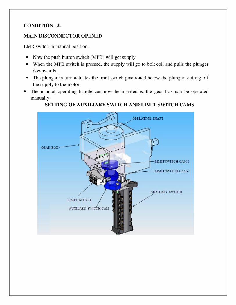
SETTING OF AUXILIARY SWITCH AND LIMIT SWITCH CAMS
OPERATION OF AUXILIARY SWITCH AND SETTING
CONSTRUCTION – 1
• Auxiliary switch is fixed to the rear sheet of the drive box along with bracket.
• A slotted lever is fixed with the drive shaft (square) of auxiliary switch and clamped
with bolt and nut.
• A cam is fixed with the main shaft (bottom side extended) of the gearbox below thelim
it switch cams and locked with screw and nut.
• A link plate is assembled with cam on one side and with auxiliary lever on the other
side.
OPERATION
Whenever the main shaft rotates either to close or open, the cam also will rotate and
operates the auxiliary switch through the link
Note:
The auxiliary switch settings are done at works. However, in case fine tuning is required
then follow the steps given below.
SETTING OF AUXILIARY SWITCH
• Keep the main Disconnector in open / closed condition.
• Keep the auxiliary switch lever in ‘NO’ position according to scheme.
• Rotate the cam and check the continuity of required contacts in auxiliary switch.
• If required loosen the pin in auxiliary switch slot and move the pin with in the slot
either inside or outside and lock it again.
• After this adjustment again operate and check for continuity.
• In the same way other positions also can be set.
LIMIT SWITCH OPERATION IN DRIVE MECHANISM
CONSTRUCTION-1
• Limit switch is fixed to a bracket and the entire set is fitted to the rear sheet of the
drive box.
• The operating cam is fixed to the main shaft (bottom side extended) of gear box and
locked with screw after positioning the cam.

OPERATION
Whenever the main shaft rotates either in close direction or open direction, the cams fitted
in the main shaft also will rotate and operates the relevant limit switch.
Note:
The limit switch settings are done at works. However, in case fine tuning is required then
follow the steps given below.
SETTING OF LIMIT SWITCH CAM 1 AND CAM 2
• Operate the disconnector manually to open position.
• Rotate the cam and see that the cam presses the limit switch roller till it disconnects the
contact (a click sound will be heard).
• Again close the disconnector manually.
• Now operate the disconnector by motor and see that the operation is completed by the
limit switch.
• If small adjustment is required, then, loosen the screw of the limit switch CAM 1.
• Rotate the cam either towards the roller or away from the roller, as required.
• Ensure the cam makes contact with the limit switch (for opening).
• Tighten the screw of the limit switch CAM 1.
• In the same way another switch (for closing – CAM 2) can be set.
18.0 ERECTION OF DOWN OPERATING PIPE:
- Identify the Main down pipe.
- Keep the Disconnector and Drive box in open position
- 5 nos. packer plates provided for any minor adjustment.
- Fix the tee bar end to the provision available on the Drive end base as shown in the fig.
- Fix the other end to drive box flange using vernier holes.
- Operate the pole manually and ensure open/close label is in proper position.
Alignment
Open and close isolator manually and observe correct functioning. Ensure that the 4
point contact grips the fixed contact trapeze firmly and centrally contact is fully engaged
and the drive lever is stopped against the toggle stop. Open and close the isolator
electrically. Make final check up of all bolts and lock them.
In the same way connect the Y & B phase poles of pantograph assembly. Individually
operate the poles manually and electrically and make sure they operate satisfactorily.
Operate through the main MGB in case of electrically ganged pantograph. In case of
any slight variation, slightly advance the opening position of the particular pantograph
which is lagging behind. This can be achieved with the help of the stopper bolt.

SECTION – D
COMMISIONING AND MAINTENANCE
19.0 COMMISIONING OF DISCONNECTOR:
• Carry out test operation manually; ensure satisfactory engagement of contacts for all
three poles. If necessary, align the contacts.
• Operate the Disconnector by power. Ensure proper open/close operation. Ensure limit
switch / auxiliary switch settings are proper.
20.0 MAINTENANCE:
Caution:
• Working on high-voltage is very dangerous; hence follow substation and other
standard safety rules.
• Don’t use emery paper for cleaning the contacts.
• Don’t try to operate the Earth switch when Disconnect or is in closed condition.
Do:
• Ensure disconnection of circuits before doing maintenance activity.
• Do proper earthing of the circuit.
• Stay clear of adjacent live parts; wherever possible, earth the adjacent live parts.
• Use proper tools.
We recommend the following inspection intervals
• Normal ambient condition: After every 5 years or after every 1000 operations
(Close/open cycle).
• Extreme ambient conditions i.e. Climate (tropical) and heavy contamination (dust, salt,
rust and Sulphur): After every 2 years or after every 500 operations (Close/open
cycle).

21.0 TOOLS AND TACKLES:
Apart from standard tools, the following are required
• Brass wire brush for cleaning of Copper surfaces.
• Steel wire brush for cleaning for Aluminum and steel surfaces.
• Contact grease (Petroleum jelly).
• Cold cleaning agent for Silver plated surfaces.
• Lint – free cloth’s
22.0 CLEANING:
Bolted or sliding contact surfaces that conduct current have an effect on the electrical
resistance of the current path. Dirty or oxidized contact surfaces increase the electrical
resistance. This will result in damage to main contacts. Hence the following cleaning
procedure shall be strictly adhered to:
Bolted Contact Surfaces: Aluminum
• Grease lightly.
• With steel wire brush, remove oxide film fully (Do not use emery paper).
• Wipe off contaminated grease immediately using lint – free cloth.
• Re-apply grease again (Immediately after cleaning with lint –free cloth).
• Bolt together treated surfaces and grease joints.
Silver plated contact surfaces.
• Clean with cold cleaning agent (do not destroy silver surfaces).
• Grease immediately.
• Bolt together treated surfaces and grease joints.
Silver plated contact surfaces (Sliding)
• Clean with cold cleaning agent (do not destroy silver surfaces).
• Grease immediately

23.0 INSPECTION CHECKS:
The following operations must be carried out during inspection
Disconnector:
• Clean contact area (Male and Female contacts). Check for any damage; if required,
change the contacts.
• Apply grease on contact surfaces.
• Clean the insulators. Check for any damage; if required, change.
• Check all bolted connections.
• Carry out three or four test operations manually.
• Reconnect the power supplies and control voltage.
• Carry our three or four test operations electrically.
24.0 RECOMMENDED SPARES:
Keep adequate quantity of following spares at all times.
• Fixed contact Assembly.
• Top Hamper Extrusion.
• Rings and Bearings.
• Motor and Gear Boxes.

www.sspower.com
RP 123kV Rev: 1 Dated: 29.05.2017


