Overlay welding of carbon and low-alloy steels with corrosion resistant alloys is a widely-used process for corrosion protection today. It allows generating a compact and tightly bonded layer of corrosion resistant alloy on a framework of less expensive material (e.g. carbon steel) which would not fulfil the corrosion resistance. Furthermore it gives the possibility of cladding more complex geometrical forms (e.g. fittings). Overlay welding is therefore increasingly applied in different segments like the Oil & Gas, Chemical Process Industry or Energy Industry.
During the overlay welding process a dilution of the weld cladding with the base metal will occur. To
save costs, fabricators try to keep the overlay layer as thin as possible, which may result in a high content of base material in the clad. Changing the composition of the clad material will change the corrosion resistance also.
For the present paper, different Nickel alloys as Alloy 625 (UNS N06625), Alloy 59 (UNS N06059),
Alloy 22 (UNS N06022), Alloy 825 (UNS N08825) and one Special Stainless Steel (Alloy 31 UNS N08031) are overlay welded in 1 to 3 layers on carbon steel. The dilution is measured by EDX-technique and is also shown as an element concentration diagram in correlation of the layer thickness.
Furthermore results of pitting corrosion in an immersion test with “Green Death” solution will be
To offset the relatively high costs of solid corrosion resistant alloy construction and still to provide a highly corrosion resistant layer of corrosion resistant alloy, overlay welding with strip and wire electrodes is now a well-established technique in chemical process equipment manufacturing and plant construction. As only the surface which is exposed to corrosive attack needs to be protected, savings on material costs can be achieved by overlay welding of corrosion resistant materials onto carbon- or low-alloy steels. The use of weld-clad mill products becomes attractive if the thickness of the wall or head is 30 mm or more. Overlay welding is certainly an alternative to explosion cladding and, to a certain extent, also to roll cladding.
At a thick-walled component the relatively thin overlay-welded surface can withstand the stress by
corrosion, high temperature, wear, cavitation or scaling. Suitable welding processes have to meet exacting requirements. Welding processes preferred
include those that exhibit low penetration, low dilution by substrate, the highest possible deposition efficiency with a uniform, finely ripped surface with good weld bead tie-in. General Aspects and Summary of Processes
Overlay welding means the application of a strongly bonded layer onto a work piece by welding in order to provide surface protection against wear, corrosion and erosion. These protective layers are applied by means of the liquid phase of the selected welding filler metal. The degree of dilution is an important quality criterion and is mainly determined by the influence of thermal factors on the base metal and the metallurgical reaction between the filler material1.
However, a dilution means a change in the composition of the layer compared with the filler metal
and therefore decisively influences the properties and corrosion resistance of the overlay. The degree of dilution is calculated by using the major elements of Ni and Fe and then averaged to arrive at a single value (equation 1)2
−−
= 100*(%)fms
fmfz
CC
CCD (1)
Where: D=% weld dilution Cfz= elemental composition of the fusion zone (weld) Cfm= elemental composition of the filler metal (wire/strip) Cs= elemental composition of the substrate (base metal) The higher the dilution the lower will be the corrosion resistance.
Compared to thermal spraying, roll bonding or explosive cladding, overlay welding is an efficient method of coating of components with complex geometries and forms a strong, impervious bond without any pores between the weld clad deposit layer and base material.
The choice of the appropriate overlay welding process is determined to a significant extent by the
filler metal with which the component is to be coated. The correct filler metal is selected by considering
2
the kinds oft attack, the material, size and shape of the component and last but not least the fabrication conditions and availability.
Overlay welding of thick-walled components and those with a large surface area is mainly carried
out by means of mechanized high performance overlay welding which enables the production of thin layers with low, uniform degree of penetration that is required to achieve a defect-free metallurgical bond1, 3.
Submerged arc strip overlay welding
FIGURE 1: Submerged Arc Strip Overlay Welding4
Figure 1 shows submerged arc strip overlay welding which is used for a large proportion of overlay welding or cladding work. The used strip has usually dimensions of 0.5X30&60mm. In this kind of welding the arc burns in a cavity beneath a molten slag blanket formed by the flux.
This slag reacts with the weld pool, resulting in desired changes in the composition of the weld.
Furthermore the slag protects the weld from reacting with the atmosphere. Welding speeds of about 12 cm/min are common4.
3
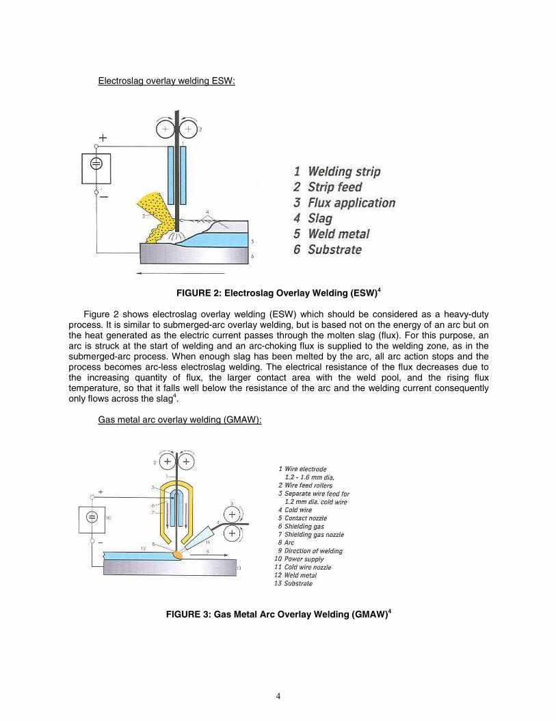
Electroslag overlay welding ESW:
FIGURE 2: Electroslag Overlay Welding (ESW)4
Figure 2 shows electroslag overlay welding (ESW) which should be considered as a heavy-duty process. It is similar to submerged-arc overlay welding, but is based not on the energy of an arc but on the heat generated as the electric current passes through the molten slag (flux). For this purpose, an arc is struck at the start of welding and an arc-choking flux is supplied to the welding zone, as in the submerged-arc process. When enough slag has been melted by the arc, all arc action stops and the process becomes arc-less electroslag welding. The electrical resistance of the flux decreases due to the increasing quantity of flux, the larger contact area with the weld pool, and the rising flux temperature, so that it falls well below the resistance of the arc and the welding current consequently only flows across the slag4.
Gas metal arc overlay welding (GMAW):
FIGURE 3: Gas Metal Arc Overlay Welding (GMAW)4
4
The procedure for pulsed-arc gas metal arc (GMA) overlay welding (figure 3) is the same as for
joining by GMA welding, except that the welding current is pulsed and the wire electrode may be oscillating during welding. In addition, it is possible to increase the deposition rate and enhance the heat input of the welding process by means of a currentless “cold wire”4.
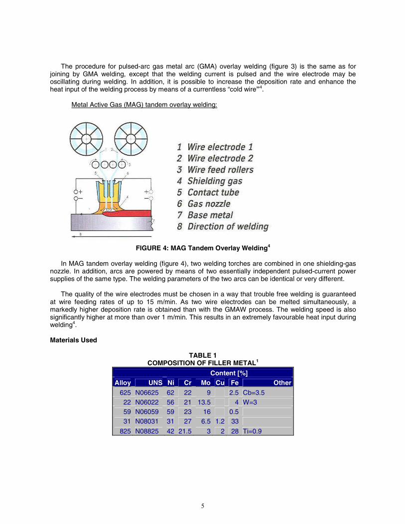
Metal Active Gas (MAG) tandem overlay welding:
FIGURE 4: MAG Tandem Overlay Welding4
In MAG tandem overlay welding (figure 4), two welding torches are combined in one shielding-gas
nozzle. In addition, arcs are powered by means of two essentially independent pulsed-current power supplies of the same type. The welding parameters of the two arcs can be identical or very different.
The quality of the wire electrodes must be chosen in a way that trouble free welding is guaranteed
at wire feeding rates of up to 15 m/min. As two wire electrodes can be melted simultaneously, a markedly higher deposition rate is obtained than with the GMAW process. The welding speed is also significantly higher at more than over 1 m/min. This results in an extremely favourable heat input during welding4. Materials Used
The composition of alloy 625 (UNS N06625) is listed in Table 1. It is a nickel-chromium-molybdenum alloy, which is stabilized with columbium. This alloy was originally developed for high-temperature applications, but is today also used in wet-corrosion service. Due to its good sensitization behaviour, it is one of the most common used welding alloys for joint and overlay welding.
Besides a good resistance against pitting and crevice corrosion, it has also superior characteristics
towards sour gas corrosion5. Alloy 22 (UNS N06022) belongs to the C-alloy family. It is resistant to many reducing media. Due to
this fact it can be used for equipment in polyvalent chemical conditions. The very low carbon content and the balanced composition reduce the tendency to form grain-boundary precipitates in the heat-affected zone during the process of welding. This makes alloy 22 a widely used alloy especially in the USA6.
Especially for severe conditions in flue gas desulphurization alloy 59 (UNS N06059) was developed
and introduced a new class of C-alloys. It has a pure ternary composition of Ni, Cr and Mo and this makes the alloy superior for duties such as handling of highly corrosive salt solution and control of critical pitting and crevice corrosion applications.
FIGURE 5: Thermal Stability of C-Alloys According to ASTM(1) G28A1
The time-temperature-sensitization diagram (figure 5) shows that alloy 59 is supremely resistant to
thermal influences. The harmonious relationship of outstanding corrosion behaviour accompanied by good workability is the special distinguishing feature of alloy 59. This alloy is therefore used in many areas of chemical process technology and other process industries. A successfully achieved NACE MR-0175 Level VII7 shows also a superior resistance towards stress corrosion cracking and makes the alloy very interesting for the Oil & Gas industry8.
(1) ASTM International (ASTM), 100 Barr Harbor Dr., West Conshohocken, PA 19428
6
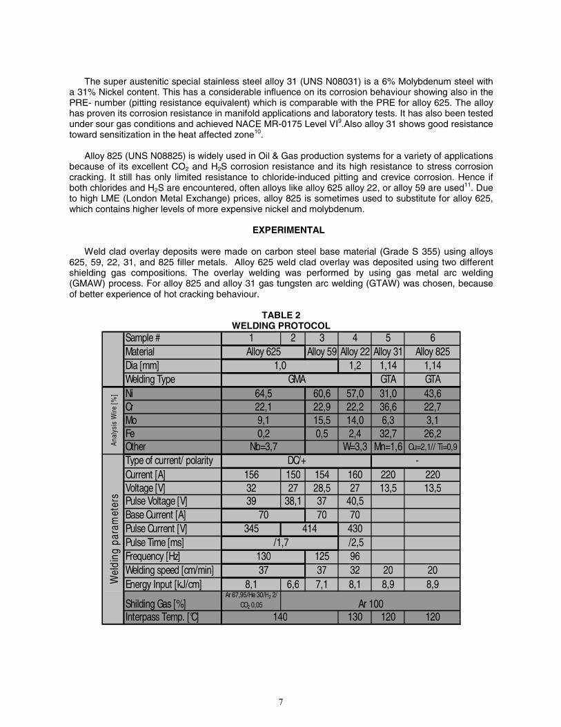
The super austenitic special stainless steel alloy 31 (UNS N08031) is a 6% Molybdenum steel with a 31% Nickel content. This has a considerable influence on its corrosion behaviour showing also in the PRE- number (pitting resistance equivalent) which is comparable with the PRE for alloy 625. The alloy has proven its corrosion resistance in manifold applications and laboratory tests. It has also been tested under sour gas conditions and achieved NACE MR-0175 Level VI9.Also alloy 31 shows good resistance toward sensitization in the heat affected zone10.
Alloy 825 (UNS N08825) is widely used in Oil & Gas production systems for a variety of applications
because of its excellent CO2 and H2S corrosion resistance and its high resistance to stress corrosion cracking. It still has only limited resistance to chloride-induced pitting and crevice corrosion. Hence if both chlorides and H2S are encountered, often alloys like alloy 625 alloy 22, or alloy 59 are used11. Due to high LME (London Metal Exchange) prices, alloy 825 is sometimes used to substitute for alloy 625, which contains higher levels of more expensive nickel and molybdenum.
EXPERIMENTAL
Weld clad overlay deposits were made on carbon steel base material (Grade S 355) using alloys
625, 59, 22, 31, and 825 filler metals. Alloy 625 weld clad overlay was deposited using two different shielding gas compositions. The overlay welding was performed by using gas metal arc welding (GMAW) process. For alloy 825 and alloy 31 gas tungsten arc welding (GTAW) was chosen, because of better experience of hot cracking behaviour.
Type of current/ polarityCurrent [A] 156 150 154 160 220 220Voltage [V] 32 27 28,5 27 13,5 13,5Pulse Voltage [V] 39 38,1 37 40,5Base Current [A] 70 70Pulse Current [V] 345 430Pulse Time [ms] /2,5Frequency [Hz] 125 96Welding speed [cm/min] 37 32 20 20Energy Input [kJ/cm] 8,1 6,6 7,1 8,1 8,9 8,9
Shilding Gas [%]Ar 67,95/He 30/H2 2/
CO2 0,05
Interpass Temp. [°C] 130 120 120
Alloy 625
Anal
ysis
Wire
[%] 64,5
22,19,10,2
Nb=3,7
1,0GMA
Wel
ding
par
amet
ers
13037
Ar 100140
-
70
DC/+
/1,7414
7
As presented in Table 2 all welding parameter were chosen with the best empirical results. The samples were produced with one to three layers. After welding the carbon steel base metal was
ground down and the samples were cut into final dimensions. The ready-cut sample pieces are welded on a piece of alloy 59 base material with filler metal alloy 59, and cut again into final dimensions by water cutting. In this way only the weld surface is exposed to the corrosive media, as would occur in actual service.
The samples were evaluated using the following tests:
1) Dilution on the sample surface: The composition of every sample and for every layer was tested
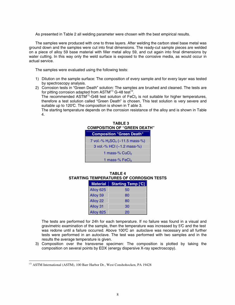
by spectroscopy analysis. 2) Corrosion tests in “Green Death” solution: The samples are brushed and cleaned. The tests are
for pitting corrosion adapted from ASTM(1) G-48 test12. The recommended ASTM(1)-G48 test solution of FeCl3 is not suitable for higher temperatures, therefore a test solution called “Green Death” is chosen. This test solution is very severe and suitable up to 120°C. The composition is shown in T able 3. The starting temperature depends on the corrosion resistance of the alloy and is shown in Table 4.
The tests are performed for 24h for each temperature. If no failure was found in a visual and gravimetric examination of the sample, then the temperature was increased by 5°C and the test was redone until a failure occurred. Above 100°C an autoclave was necessary and all further tests were performed in an autoclave. The test was performed with two samples and in the results the average temperature is given.
3) Composition over the transverse specimen: The composition is plotted by taking the composition on several points by EDX (energy dispersive X-ray spectroscopy).
(1) ASTM International (ASTM), 100 Barr Harbor Dr., West Conshohocken, PA 19428
8
RESULTS Figure 6 shows a selection of the appearance of the welded surface of the corrosion coupons after
exposure in the immersion test. It also shows one sample before it was tested.
Sample 1 Alloy 625 Sample 5 Alloy 31
Sample 6 Alloy 825 Sample 1 Alloy 625 before testing
FIGURE 6: Sample 1, 5 and 6 after Immersion Testing and Sample 1 before Testing (all in cm
and °C)
Table 5 shows an overview of the dilution results of all tested alloys. It shows the analysis of the
surface of each layer and for each alloy for the elements nickel, chromium, molybdenum, tungsten, and iron. It was analysed in the internal ThyssenKrupp VDM laboratory in Unna/ Germany by spectroscopic analysis.
Furthermore table 5 points out the nickel dilution calculated by equation 1. To estimate the resistance of a stainless steel or nickel alloy against pitting corrosion, the PRE
number (pitting resistance equivalent) is a first quantitative approach (equation 2)1
10
WMoCrPRE %6.1%3.3% ×+×+= (2)
The higher the PRE number, the higher the failure temperature in an immersion test. The PRE number and the failure temperature in the immersion test are given in the last two lines of Table 5.
Alloy 625
Alloy 625 was welded with two different shielding gases. Sample 1 was welded with active gas and
Sample 2 with pure Argon. The compositions of both samples are shown in table 2; both are comparable. Still the immersion
test failure temperature shows a big gap for the 2 layer sample. The active gas mixture causes a preheating effect of the base material and the 2% H2 in the gas
causes a contraction of the arc, resulting in an increase of the weld pool temperature. These effects support the wettability of the melt and may result in a different weld bead and corrosion resistance.
The iron dilution in the first layer with 1.9% (active gas) and 4.2% (argon) is not constant, but
becomes low with the second layer and is even 0 at the third layer for both active gas and argon welded samples.
Alloy 59 and Alloy 22
Alloy 59 as well as alloy 22 show a high amount of dilution in the first welding layer. Nevertheless
both alloys perform very well as shown in the immersion test. Test results for both reached 100°C with the first layer. Above 100°C the tests were perform ed in an autoclave. Both alloys reached high temperatures of 110°C (Alloy 22) and 115°C (Alloy 5 9) even in the second layer and also for the third layer.
Like the other tested samples, starting with the second layer the dilution was found to be relatively
low and approaching almost 0%. Furthermore the content of iron in the third layer of alloy 59 is much lower compared to alloy 22. The iron content reflects the composition of the welding material. Alloy 59 has an almost pure ternary composition of nickel, chromium and molybdenum with only traces of iron. Alloy 22 has ~4% iron, which is also reflected in the results.
Both alloys are high performing C-Alloys with comparable PRE Numbers. This is shown in the
corrosion resistance. They can be used for applications with harsh corrosion conditions and show a very good weldability, but it still has to be taken into consideration, that alloy 59 shows a slight advantage compared to alloy 22.
Alloy 31
Alloy 31 is a high alloyed stainless steel. The alloy shows a failure temperature of 35°C for the firs t
layer and 40°C for all other layers. In this case a lloy 31 was tested in “Green Death” solution, which is used for testing nickel alloys. The literature recommends using FeCl3 solution for high alloyed stainless steels1. In FeCl3 tests with alloy 31 base material, this high alloyed stainless steel attains almost the same immersion failure temperature as alloy 625.
Probably Green Death is too harsh for this alloy, so it needs to be checked with FeCl3 solution, too.
Furthermore alloy 31 contains nitrogen, which is also helpful for corrosion resistance under normal circumstances1. In further examinations the influence of nitrogen content in welded materials need to be analysed.
11
Alloy 31 shows a high dilution even for the second layer, which might be related to the GTAW
process. This is surprising since normally GTAW shows a lower dilution than GMAW. This fact might be related to the chosen welding parameter, which has to be applied for carrying out these weldings.
Alloy 825
Alloy 825 shows very high dilution in all layers. Even in the third layer the dilution shows 1.8%,
which is the highest dilution of all tested alloys. As assumed for alloy 31 this might be connected to the GTAW process used to make the overlay weld deposit.
The low failure temperature in the immersion test was to be expected. Alloy 825 has a very low
content in molybdenum, which is detrimental for the corrosion resistance (Mo helps to resist pitting corrosion, which is shown in equation 2), especially in reducing media1.
For alloy 825 base material, much lower CPT (critical pitting temperature) values than for alloy 31
are reported1. In our corrosion test, only the first layer sample shows alloy 825 a lower CPT than alloy 31.
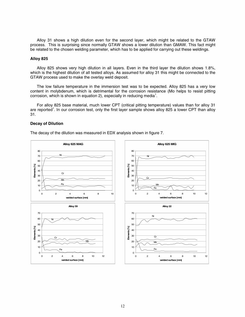
Decay of Dilution
The decay of the dilution was measured in EDX analysis shown in figure 7.
Alloy 625 MAG
0
10
20
30
40
50
60
70
80
0 2 4 6 8 10
welded surface [mm]
Ele
men
ts [%
] .
Ni
Cr
Mo
Fe
Alloy 625 MIG
0
10
20
30
40
50
60
70
80
0 2 4 6 8 10 12
welded surface [mm]
Ele
men
ts [%
] .
Ni
Cr
Mo
Fe
Alloy 59
0
10
20
30
40
50
60
70
0 2 4 6 8 10 12
welded surface [mm]
Ele
men
ts [%
] .
Ni
Cr
Mo
Fe
Alloy 22
0
10
20
30
40
50
60
70
0 2 4 6 8 10 12
welded surface [mm]
Ele
men
ts [%
] .
Ni
Cr
Mo
Fe
12
Alloy 825
0
5
10
15
20
25
30
35
40
45
50
0 1 2 3 4 5 6 7
welded surface [mm]
Ele
men
ts [%
] .
Ni
Cr
Mo
Fe
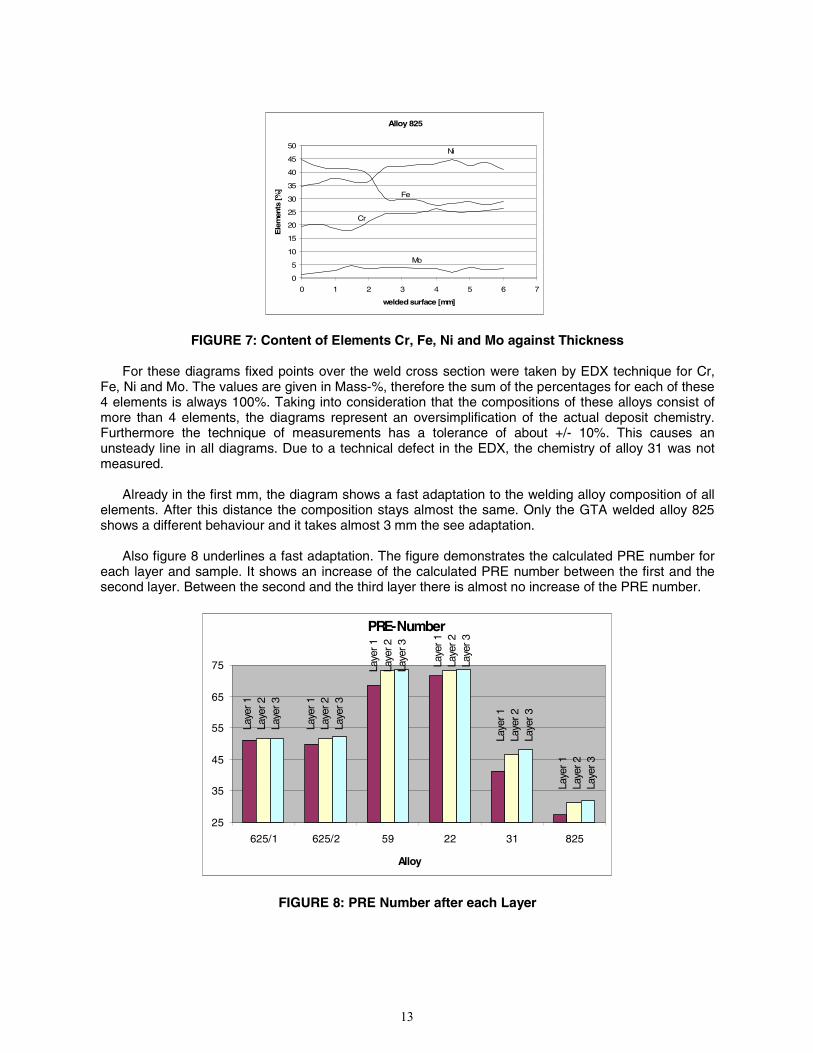
FIGURE 7: Content of Elements Cr, Fe, Ni and Mo against Thickness
For these diagrams fixed points over the weld cross section were taken by EDX technique for Cr, Fe, Ni and Mo. The values are given in Mass-%, therefore the sum of the percentages for each of these 4 elements is always 100%. Taking into consideration that the compositions of these alloys consist of more than 4 elements, the diagrams represent an oversimplification of the actual deposit chemistry. Furthermore the technique of measurements has a tolerance of about +/- 10%. This causes an unsteady line in all diagrams. Due to a technical defect in the EDX, the chemistry of alloy 31 was not measured.
Already in the first mm, the diagram shows a fast adaptation to the welding alloy composition of all
elements. After this distance the composition stays almost the same. Only the GTA welded alloy 825 shows a different behaviour and it takes almost 3 mm the see adaptation.
Also figure 8 underlines a fast adaptation. The figure demonstrates the calculated PRE number for
each layer and sample. It shows an increase of the calculated PRE number between the first and the second layer. Between the second and the third layer there is almost no increase of the PRE number.
PRE-Number
25
35
45
55
65
75
625/1 625/2 59 22 31 825
Alloy
Laye
r 1La
yer 2
Laye
r 3
Laye
r 1La
yer 2
Laye
r 3
Laye
r 1La
yer 2
Laye
r 3
Laye
r 1La
yer 2
Laye
r 3
Laye
r 1La
yer 2
Laye
r 3
Laye
r 1La
yer 2
Laye
r 3
FIGURE 8: PRE Number after each Layer
13
This effect is also proven by figure 9, which shows an overview of the average dilution of nickel as
an average value over all alloys. Also this figure shows a strong decay between the first and the second layer but almost no decay between the second and the third layer anymore.
Avr. Dillution
0
1
2
3
4
5
6
7
8
9
1 2 3
Layer welded
Avr
. Dill
utio
n [%
Ni]
FIGURE 9: Content of Dilution as a Middle Value over all Alloys
CONCLUSION
1. Considering all data gives a ranking for all tested alloys: alloy 59 � alloy 22�alloy 625 MIG�alloy 625 MAG�alloy 825� alloy 31
2. The C-alloys like alloy 59 and alloy 22 show a much better corrosion resistance than alloy 625 and should therefore be taken into consideration for harsher environments.
3. The corrosion resistance at the first layer is much lower than the second layer. Still C-alloys like alloy 59 and alloy 22 showing a better corrosion resistance after the first layer than all other alloys after 3 layers.
4. Alloy 825 and alloy 31 show the lowest pitting resistance in the test, which needs to be taken into consideration if used in environments with the danger of pitting corrosion (e.g. very high chloride containing environments).
5. For welding at least two layers should be considered because the second layer shows a better homogeneity. For high demanding applications even three layers should be considers.
ACKNOWLEDGMENTS
All weld specimens were welded by Mr. Leinweber and Mr. Rechenberg at the ThyssenKrupp
Welding Lab in Altena. The corrosion testing was done by Mr. Stenner at the ThyssenKrupp Corrosion Lab in Altena. The EDX examination was done by Mr. Kossowski at ThyssenKrupp in Unna.
Furthermore I would like to thank Mr. Behrens and Mrs. Alves for fruitful discussions.
Avr. Dilution
14
REFERENCES
1 Nickel alloys and high-alloy special stainless steels, Ed. U. Heubner, J. Klöwer, 3rd ed., Expert Verlag, Renningen, 2003
2 Larry Paul, Corrosion Paper No. 09182, NACE International, Houston, 2009 3 Guidelines for the welded fabrication of nickel alloys for corrosion-resistant service, NiDi, 1994 4 ThyssenKrupp VDM, Publication N 568, Welding consumables from ThyssenKrupp VDM, Jan.
2007, Werdohl, Germany 5 ThyssenKrupp VDM, Material Data Sheet Nicrofer 6020 hMo- Alloy 625, Aug. 2007, Werdohl,
Germany 6 ThyssenKrupp VDM, Material Data Sheet Nicrofer 5621hMoW- Alloy 22, Mar. 2007, Werdohl,
Germany 7 NACE Standard MR0175, NACE International, Houston, TX, 2003 8 Dirk Aberle, D.C. Agarwal, Corrosion Paper No. 08085, NACE International, Houston, 2008 9 D.C. Agarwal, U Brill, “Application case histories of Ni-Cr-Mo and 6Mo alloys in the
petrochemical and chemical process industries”, Stainless Steel World, May 2002 10 S. A. McCoy, “New generation of tubular materials for downhole and subsurface umbilical
applications in the oil and gas industry”, Stainless Steel World, March 2005 11 J. Klöwer, H. Schlerkmann, R. Pöpperling, Corrosion Paper No. 01004, NACE International,
Houston, 2001 12 G48-03 Standard Test Methods for Pitting and Crevice Corrosion Resistance of Stainless Steels
and Related Alloys by Use of Ferric Chloride Solution, ASTM INTERNATIONAL, West Conshohocken, USA, 2005