PAPER SHREDDER MERCURY PAPER SHREDDER MERCURY RDS2050,RDX1750,RDS2270,RDX1970 ILLUSTRATED PARTS LIST Acco Service Division, Halesowen Industrial Estate, Hereward Rise, Halesowen, West Midlands B62 8AN Telephone 0845 658 6600 Fax 0121 501 3991 D Mead Issue 1 Page 1 of 24 March 2007
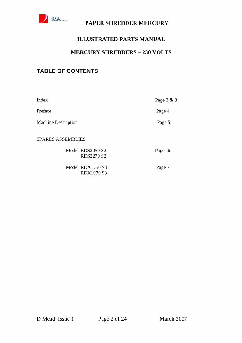
Index Page 2 & 3 Preface Page 4 Machine Description Page 5 SPARES ASSEMBLIES Model RDS2050 S2 Pages 6 RDS2270 S2 Model RDX1750 S3 Page 7 RDX1970 S3
D Mead Issue 1 Page 2 of 24 March 2007
PAPER SHREDDER MERCURY
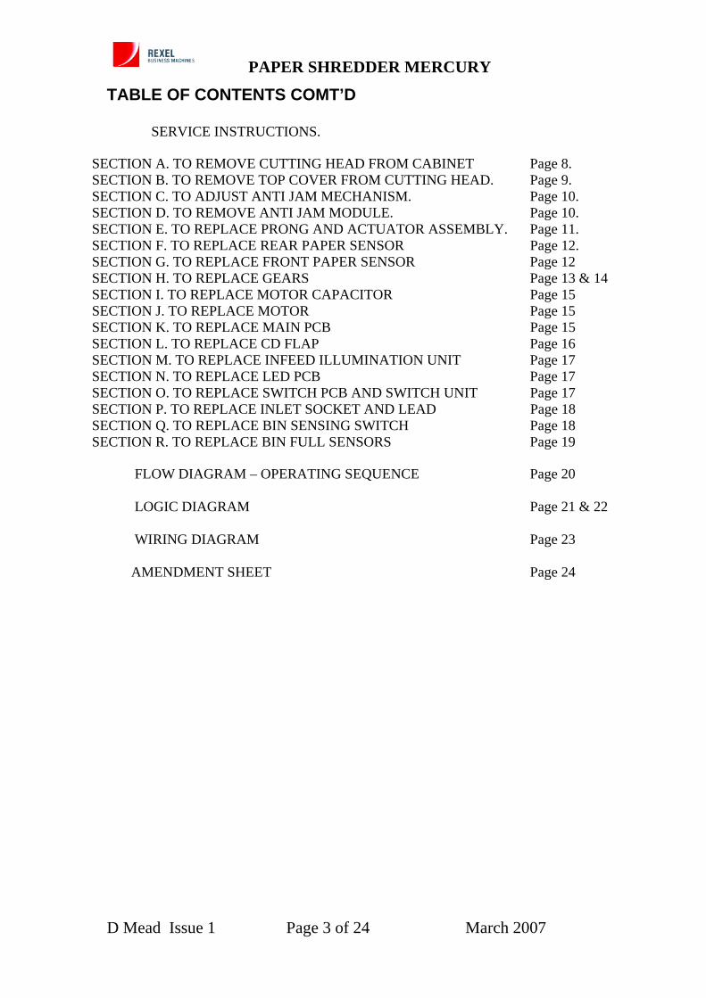
TABLE OF CONTENTS COMT’D SERVICE INSTRUCTIONS.
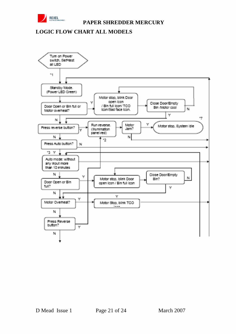
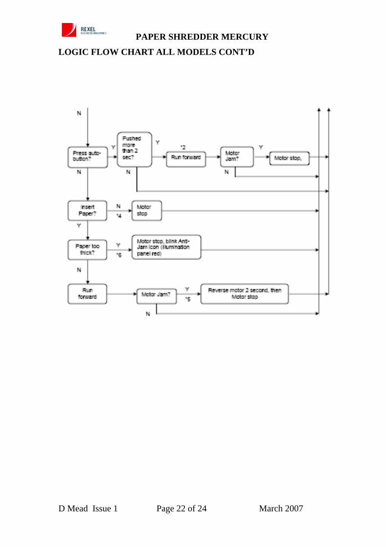
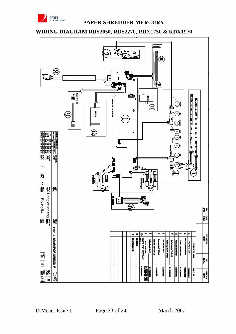
SECTION A. TO REMOVE CUTTING HEAD FROM CABINET Page 8. SECTION B. TO REMOVE TOP COVER FROM CUTTING HEAD. Page 9. SECTION C. TO ADJUST ANTI JAM MECHANISM. Page 10. SECTION D. TO REMOVE ANTI JAM MODULE. Page 10. SECTION E. TO REPLACE PRONG AND ACTUATOR ASSEMBLY. Page 11. SECTION F. TO REPLACE REAR PAPER SENSOR Page 12. SECTION G. TO REPLACE FRONT PAPER SENSOR Page 12 SECTION H. TO REPLACE GEARS Page 13 & 14 SECTION I. TO REPLACE MOTOR CAPACITOR Page 15 SECTION J. TO REPLACE MOTOR Page 15 SECTION K. TO REPLACE MAIN PCB Page 15 SECTION L. TO REPLACE CD FLAP Page 16 SECTION M. TO REPLACE INFEED ILLUMINATION UNIT Page 17 SECTION N. TO REPLACE LED PCB Page 17 SECTION O. TO REPLACE SWITCH PCB AND SWITCH UNIT Page 17 SECTION P. TO REPLACE INLET SOCKET AND LEAD Page 18 SECTION Q. TO REPLACE BIN SENSING SWITCH Page 18 SECTION R. TO REPLACE BIN FULL SENSORS Page 19 FLOW DIAGRAM – OPERATING SEQUENCE Page 20 LOGIC DIAGRAM Page 21 & 22 WIRING DIAGRAM Page 23 AMENDMENT SHEET Page 24
D Mead Issue 1 Page 3 of 24 March 2007
PAPER SHREDDER MERCURY
PREFACE
SERVICE PREPARATION This manual provides the instructions for the replacement of all the components that may become worn or damaged during normal usage of the machine. “Illustrated Parts Lists” - For each machine give full details of the replacement part numbers with supporting diagrams to show the location of the components. “Service Instructions” - For each machine give the recommended servicing procedure with supporting pictorial diagrams for added clarity WARNING 1. Check the machine RATING PLATE DETAILS are compatible with the electrical
mains supply. 2. Disconnect the electrical mains supply before removing any covers. 3. The machine MUST have a sound Electrical Earth Connection. NOTE: THE ELECTRIC MOTOR IS PROTECTED BY AN AUTOMATIC THERMAL OVERLOAD CUT-OUT Product Testing after Servicing or Repair. IMPORTANT. If any electrical component has been changed, an electrical connection broken and remade, or any wiring disturbed, the product being repaired or serviced must be flash tested or PAT tested. This test must be carried before a product is handed back or returned to the customer or returned to stock. The test must be appropriate for the machine being repaired. E.g. double insulated or earthed. A competent person should conduct the test and keep a log of all machines tested, the serial number of the machine, the details of the test, the test results and the date the test was carried out.
D Mead Issue 1 Page 4 of 24 March 2007
PAPER SHREDDER MERCURY
DESCRIPTION
A range of straight and crosscut shredders using either built up or solid shafts. ANTI JAM FEATURE All models include an anti jam feature if documents above a set thickness are fed into the infeed slot. The documents will not have entered the cutters. The thickness is equal to the nominal sheet capacity of 70gsm paper. The documents can then be easily removed from the machine and sheets removed. The device will also stop the machine if an increase in document thickness is detected while shredding again allowing easy removal of the access sheets before they enter the cutters. The document thickness is measured by a trigger coupled to an accurate measuring sensor. A pair of rollers and servo operated pressure pads are incorporated to prevent movement of the paper, passing through the cutters, generating false signals. It is possible to reverse the machine if necessary.
D Mead Issue 1 Page 5 of 24 March 2007
PAPER SHREDDER MERCURY
MODEL RDS2050 S2 & RDS2270 S2 SPARES ASSEMBLIES
Section Description Part No Comments D Anti Jam Module. 1001336 E Prong and Actuator
Assy. 1001337
F Paper Sensor Rear 1001338 G Paper Sensor Front 1001338 H Gear Kit 1001343 Including circlips I Motor Capacitor 1001342 J Motor 1001339 K Main PCB 1001345 L CD Flap 1001334 M Infeed Illumination
Unit 1001335
N LED PCB 1001333 O Switch PCB Assy 1001332 Including switch buttons. P Mains Inlet Socket and
lead assy 1001348
Q Bin Sensor Micro Switch
1001347
R Bin Full Sensor Kit. 1001346
D Mead Issue 1 Page 6 of 24 March 2007
PAPER SHREDDER MERCURY
MODEL RDX1750 & RDX1970 SPARES ASSEMBLIES Section
Description Part No Comments
D Anti Jam Module. 1001336 E Prong and Actuator Assy. 1001337 F Paper Sensor Rear 1001338 G Paper Sensor Front 1001338 H Gear Kit 1001344 Including circlips I Motor Capacitor 1001342 J Motor 1001340 RDX 1750 Motor 1001341 RDX 1970 K Main PCB 1001345 L CD Flap Assy 1001334 M Infeed Illumination Unit 1001335 N LED PCB 1001333 O Switch PCB Assy 1001332 Including switch buttons. P Mains Inlet Socket and
lead assy 1001348
Q Bin Sensor Micro Switch 1001347 R Bin Full Sensor Kit. 1001346
D Mead Issue 1 Page 7 of 24 March 2007
PAPER SHREDDER MERCURY
REPAIR PROCEDURES FOR MODELS RDS2050 S2, RDS2270 S2, RDX1750 & RDX1970. A. TO REMOVE CUTTING HEAD FROM CABINET
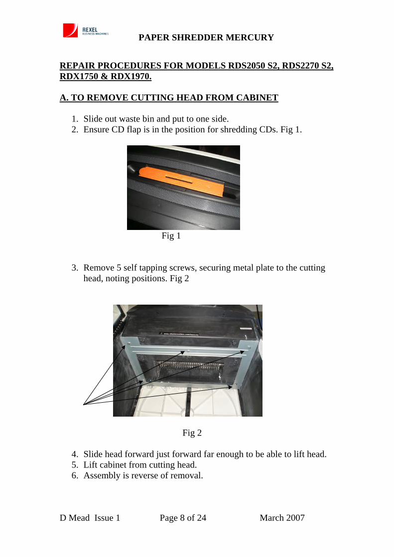
1. Slide out waste bin and put to one side. 2. Ensure CD flap is in the position for shredding CDs. Fig 1.
Fig 1
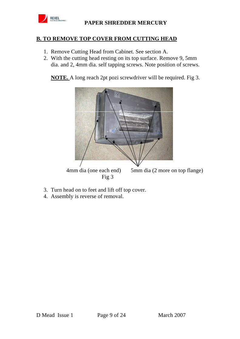
3. Remove 5 self tapping screws, securing metal plate to the cutting head, noting positions. Fig 2
Fig 2
4. Slide head forward just forward far enough to be able to lift head. 5. Lift cabinet from cutting head. 6. Assembly is reverse of removal.
D Mead Issue 1 Page 8 of 24 March 2007
PAPER SHREDDER MERCURY
B. TO REMOVE TOP COVER FROM CUTTING HEAD
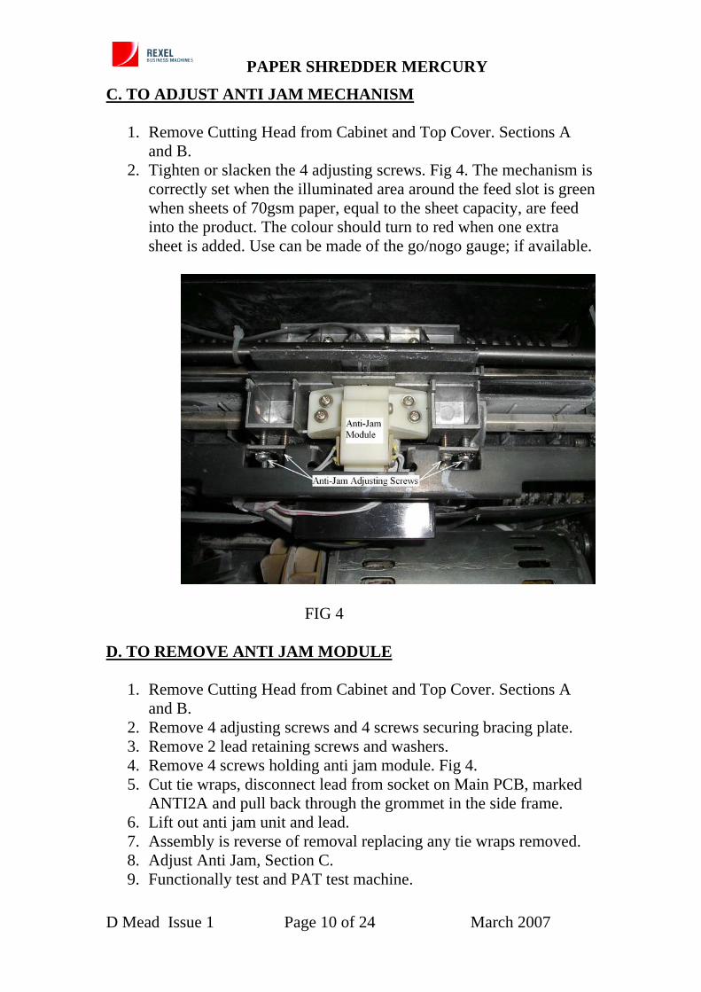
1. Remove Cutting Head from Cabinet. See section A. 2. With the cutting head resting on its top surface. Remove 9, 5mm
dia. and 2, 4mm dia. self tapping screws. Note position of screws.
NOTE. A long reach 2pt pozi screwdriver will be required. Fig 3.
4mm dia (one each end) 5mm dia (2 more on top flange) Fig 3
3. Turn head on to feet and lift off top cover. 4. Assembly is reverse of removal.
D Mead Issue 1 Page 9 of 24 March 2007
PAPER SHREDDER MERCURY
C. TO ADJUST ANTI JAM MECHANISM
1. Remove Cutting Head from Cabinet and Top Cover. Sections A and B.
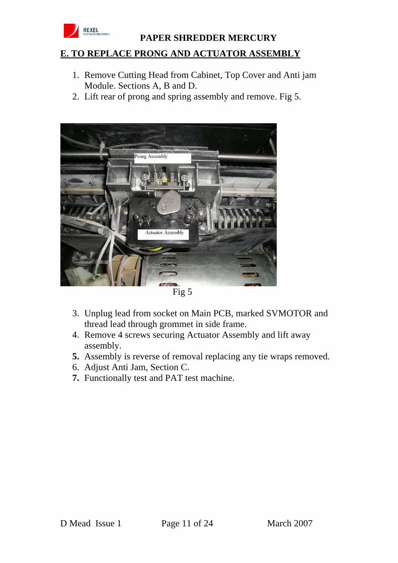
2. Tighten or slacken the 4 adjusting screws. Fig 4. The mechanism is correctly set when the illuminated area around the feed slot is green when sheets of 70gsm paper, equal to the sheet capacity, are feed into the product. The colour should turn to red when one extra sheet is added. Use can be made of the go/nogo gauge; if available.
FIG 4
D. TO REMOVE ANTI JAM MODULE
1. Remove Cutting Head from Cabinet and Top Cover. Sections A and B.
2. Remove 4 adjusting screws and 4 screws securing bracing plate. 3. Remove 2 lead retaining screws and washers. 4. Remove 4 screws holding anti jam module. Fig 4. 5. Cut tie wraps, disconnect lead from socket on Main PCB, marked
ANTI2A and pull back through the grommet in the side frame. 6. Lift out anti jam unit and lead. 7. Assembly is reverse of removal replacing any tie wraps removed. 8. Adjust Anti Jam, Section C. 9. Functionally test and PAT test machine.
D Mead Issue 1 Page 10 of 24 March 2007
PAPER SHREDDER MERCURY
E. TO REPLACE PRONG AND ACTUATOR ASSEMBLY
1. Remove Cutting Head from Cabinet, Top Cover and Anti jam Module. Sections A, B and D.
2. Lift rear of prong and spring assembly and remove. Fig 5.
Fig 5
3. Unplug lead from socket on Main PCB, marked SVMOTOR and thread lead through grommet in side frame.
5. Assembly is reverse of removal replacing any tie wraps removed. 6. Adjust Anti Jam, Section C. 7. Functionally test and PAT test machine.
D Mead Issue 1 Page 11 of 24 March 2007
PAPER SHREDDER MERCURY
F. TO REPLACE REAR PAPER SENSOR
1. Remove Cutting Head from Cabinet, Top Cover, Anti jam Module and Actuator Assembly. Sections A, B, D and E.
2. Unplug lead from socket on Main PCB, marked AUTO2A and thread lead through grommet in side frame.
3. The sensor is held in place my hot melt glue. Once this is removed the sensor can be prised out with a small screwdriver and pliers. Fig 6.
4. Assembly is reverse of removal replacing any tie wraps removed. 5. Adjust Anti Jam, Section C. 6. Functionally test and PAT test machine.
G. TO REPLACE FRONT PAPER SENSOR
1. Remove Cutting Head from Cabinet and Top Cover. Sections A and B.
2. Remove 2 screws securing tie bar. Pull tie bar from between side frames.
3. Unplug lead from socket on Main PCB, marked AUTO1A and thread lead through grommet in side frame.
4. The sensor is held in place my hot melt glue. Once this is removed the sensor can be prised out with a small screwdriver and pliers. Fig 6
5. Assembly is reverse of removal replacing any tie wraps removed. 6. Adjust Anti Jam, Section C. 7. Functionally test and PAT test machine.
D Mead Issue 1 Page 12 of 24 March 2007
PAPER SHREDDER MERCURY
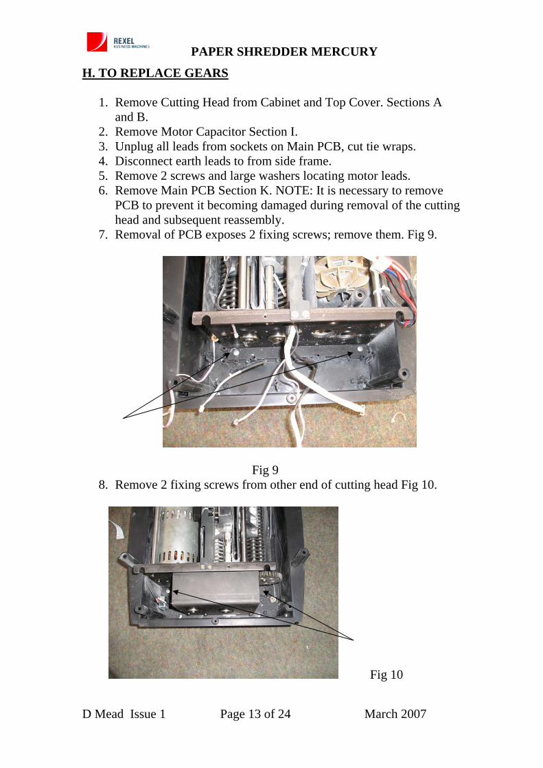
H. TO REPLACE GEARS
1. Remove Cutting Head from Cabinet and Top Cover. Sections A and B.
2. Remove Motor Capacitor Section I. 3. Unplug all leads from sockets on Main PCB, cut tie wraps. 4. Disconnect earth leads to from side frame. 5. Remove 2 screws and large washers locating motor leads. 6. Remove Main PCB Section K. NOTE: It is necessary to remove
PCB to prevent it becoming damaged during removal of the cutting head and subsequent reassembly.
Fig 9 8. Remove 2 fixing screws from other end of cutting head Fig 10.
Fig 10
D Mead Issue 1 Page 13 of 24 March 2007
PAPER SHREDDER MERCURY
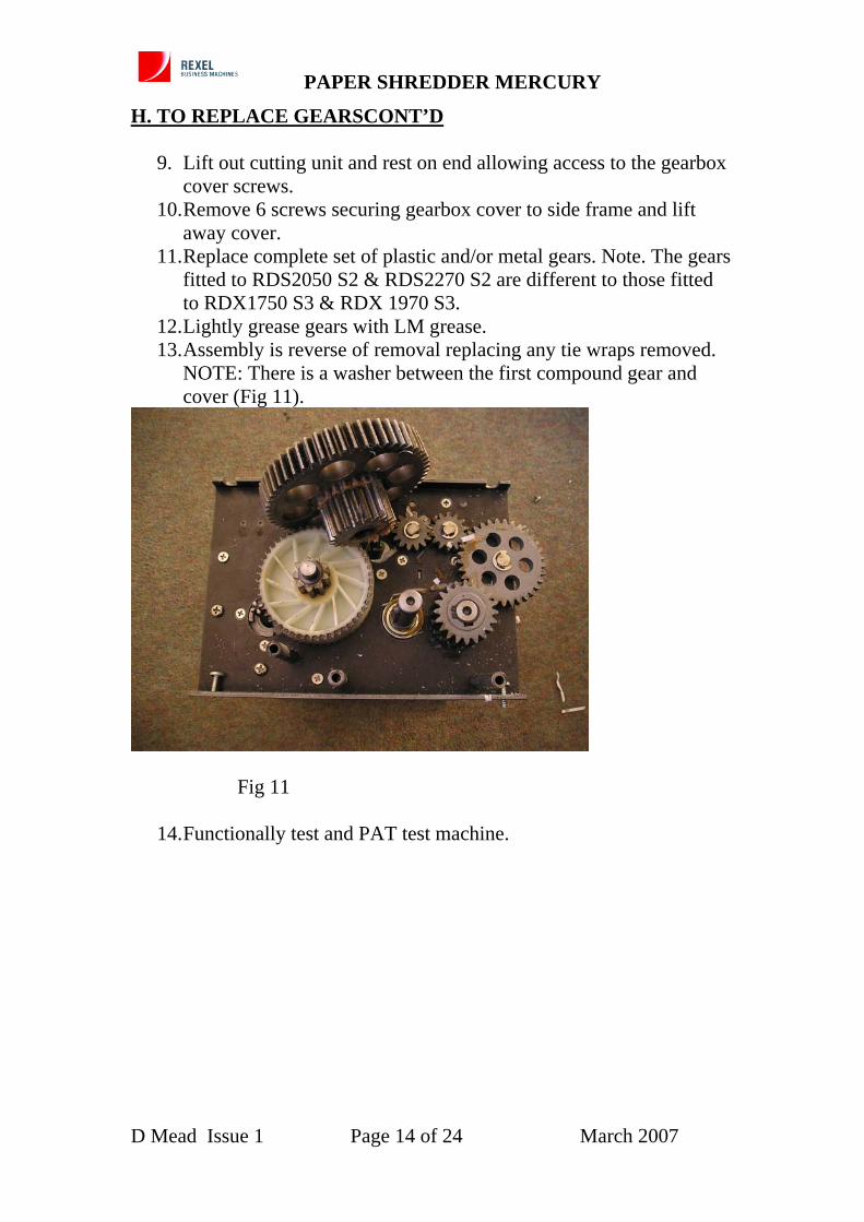
H. TO REPLACE GEARSCONT’D 9. Lift out cutting unit and rest on end allowing access to the gearbox
cover screws. 10. Remove 6 screws securing gearbox cover to side frame and lift
away cover. 11. Replace complete set of plastic and/or metal gears. Note. The gears
fitted to RDS2050 S2 & RDS2270 S2 are different to those fitted to RDX1750 S3 & RDX 1970 S3.
12. Lightly grease gears with LM grease. 13. Assembly is reverse of removal replacing any tie wraps removed.
NOTE: There is a washer between the first compound gear and cover (Fig 11).
Fig 11
14. Functionally test and PAT test machine.
D Mead Issue 1 Page 14 of 24 March 2007
PAPER SHREDDER MERCURY
I. TO REPLACE MOTOR CAPACITOR
1. Remove Cutting Head from Cabinet and Top Cover. Sections A and B.
2. Unplug lead from socket on Main PCB, marked TCO4 and cut tie wrap.
3. Remove nut and washer securing capacitor and remove. 4. Assembly is reverse of removal replacing any tie wraps removed. 5. Functionally test and PAT test machine.
J. TO REPLACE MOTOR
1. Remove Cutting Head from Cabinet, Top Cover, Main PCB and Gears. Sections A, B, H and K.
2. Remove two compound gears and stub shafts. 3. Remove 2 tie bars supporting the fan end of the motor. 4. Remove 8 screws securing motor, remove motor. 5. Assembly is reverse of removal replacing any tie wraps removed.
NOTE: There is a washer between the first compound gear and cover.
6. Functionally test and PAT test machine. K. TO REPLACE MAIN PCB
1. Remove Cutting Head from Cabinet and Top Cover. Sections A and B.
2. Unplug leads from Sockets marked CD-1A, CON1A, CON2A and Switch PCB mains lead from main PCB to release top cover assy.
3. Unplug remaining leads from sockets on main PCB. 4. Unscrew earth leads from side frame, noting positions. 5. Remove 6 screws securing PCB and lift out PCB. 6. Assembly is reverse of removal replacing any tie wraps removed.
Connecting Bin Full Sensors to sockets BIN1A and BIN2A, Auto Start Sensors to sockets AUTO1A and AUTO2A, Anti Jam module to ANTI2A, Prong Actuator assy. to SVMOTOR, Bin Sensor Switch to SW7, The Motor Capacitor to TCO4 and Motor to SW3. For connections to top cover see 2 above.
7. Functionally test and PAT test machine.
D Mead Issue 1 Page 15 of 24 March 2007
PAPER SHREDDER MERCURY
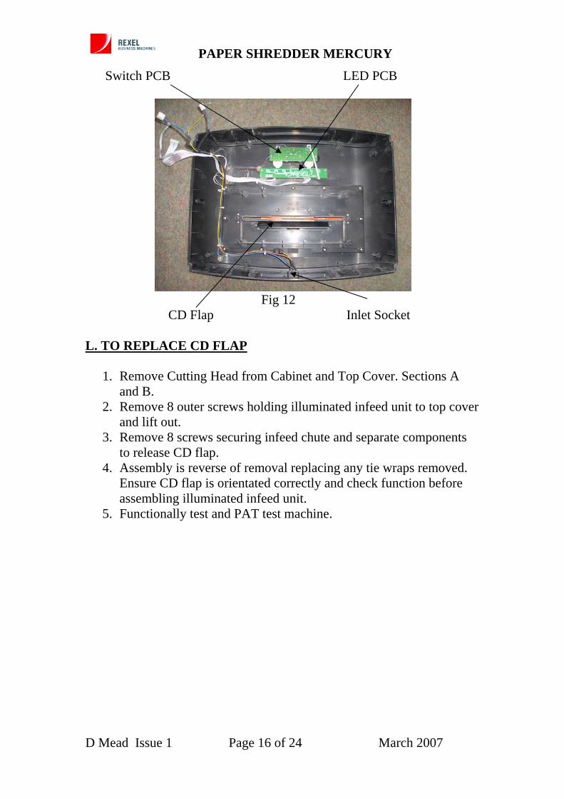
Switch PCB LED PCB
Fig 12 CD Flap Inlet Socket L. TO REPLACE CD FLAP
1. Remove Cutting Head from Cabinet and Top Cover. Sections A and B.
2. Remove 8 outer screws holding illuminated infeed unit to top cover and lift out.
3. Remove 8 screws securing infeed chute and separate components to release CD flap.
4. Assembly is reverse of removal replacing any tie wraps removed. Ensure CD flap is orientated correctly and check function before assembling illuminated infeed unit.
5. Functionally test and PAT test machine.
D Mead Issue 1 Page 16 of 24 March 2007
PAPER SHREDDER MERCURY
M. TO REPLACE INFEED ILLUMINATION UNIT
1. Remove Cutting Head from Cabinet and Top Cover. Sections A and B.
2. Remove 4 screws and large washers locating leads. 3. Remove 3 screws securing LED PCB unit. 4. Unplug leads from sockets CNS1 and CNS2 on LED PCB. 5. Remove 8 screws securing Infeed Illumination Unit and remove. 6. Remove 8 screws securing Throat moulding, CD flap and
Translucent panel. 7. Separate parts and put to one side. 8. Assembly is reverse of removal replacing any tie wraps removed..
Ensure CD flap is orientated correctly and check function before assembling illuminated infeed unit.
9. Functionally test and PAT test machine. N. TO REPLACE LED PCB
1. Remove Cutting Head from Cabinet and Top Cover. Sections A and B.
2. Remove 1 screw and large washer locating leads. 3. Remove 3 screws securing LED PCB unit. 4. Remove 3 screws securing switch PCB. 5. Disconnect lead from P3-1 socket on Switch PCB. 6. Unplug leads from sockets CNS1 and CNS2 on LED PCB. 7. Unplug leads from sockets CON1A and CON2A on main PCB. 8. LED PCB unit can now be removed. 9. Assembly is reverse of removal replacing any tie wraps removed. 10. Functionally test and PAT test machine.
O. TO REPLACE SWITCH PCB AND SWITCH UNIT
1. Remove Cutting Head from Cabinet and Top Cover. Sections A and B.
2. Remove 2 screws and large washers locating leads. 3. Remove 3 screws securing switch PCB. 4. Unplug mains lead from socket on main PCB. 5. Disconnect lead from P3-1 socket on Switch PCB and remove it. 6. Remove screw securing each switch unit and remove. 7. Assembly is reverse of removal replacing any tie wraps removed. 8. Functionally test and PAT test machine.
D Mead Issue 1 Page 17 of 24 March 2007
PAPER SHREDDER MERCURY
P. TO REPLACE MAINS LEAD
1. 1. Remove Cutting Head from Cabinet and Top Cover. Sections A and B.
2. Unplug lead from main PCB marked POWER. 3. Remove screw securing earth lead to side frame. 4. Remove screw and large washer, from top cover, holding lead in
place. 5. Remove 2 screws and washers securing inlet socket to top cover. 6. Replace tie wraps, fit top cover to housing and complete cutting
head assembly to cabinet. 7. Functionally test and PAT test machine.
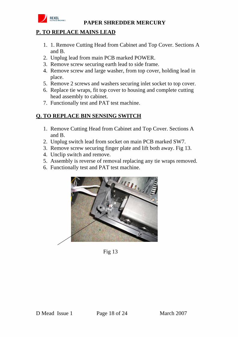
Q. TO REPLACE BIN SENSING SWITCH
1. Remove Cutting Head from Cabinet and Top Cover. Sections A and B.
2. Unplug switch lead from socket on main PCB marked SW7. 3. Remove screw securing finger plate and lift both away. Fig 13. 4. Unclip switch and remove. 5. Assembly is reverse of removal replacing any tie wraps removed. 6. Functionally test and PAT test machine.
Fig 13
D Mead Issue 1 Page 18 of 24 March 2007
PAPER SHREDDER MERCURY
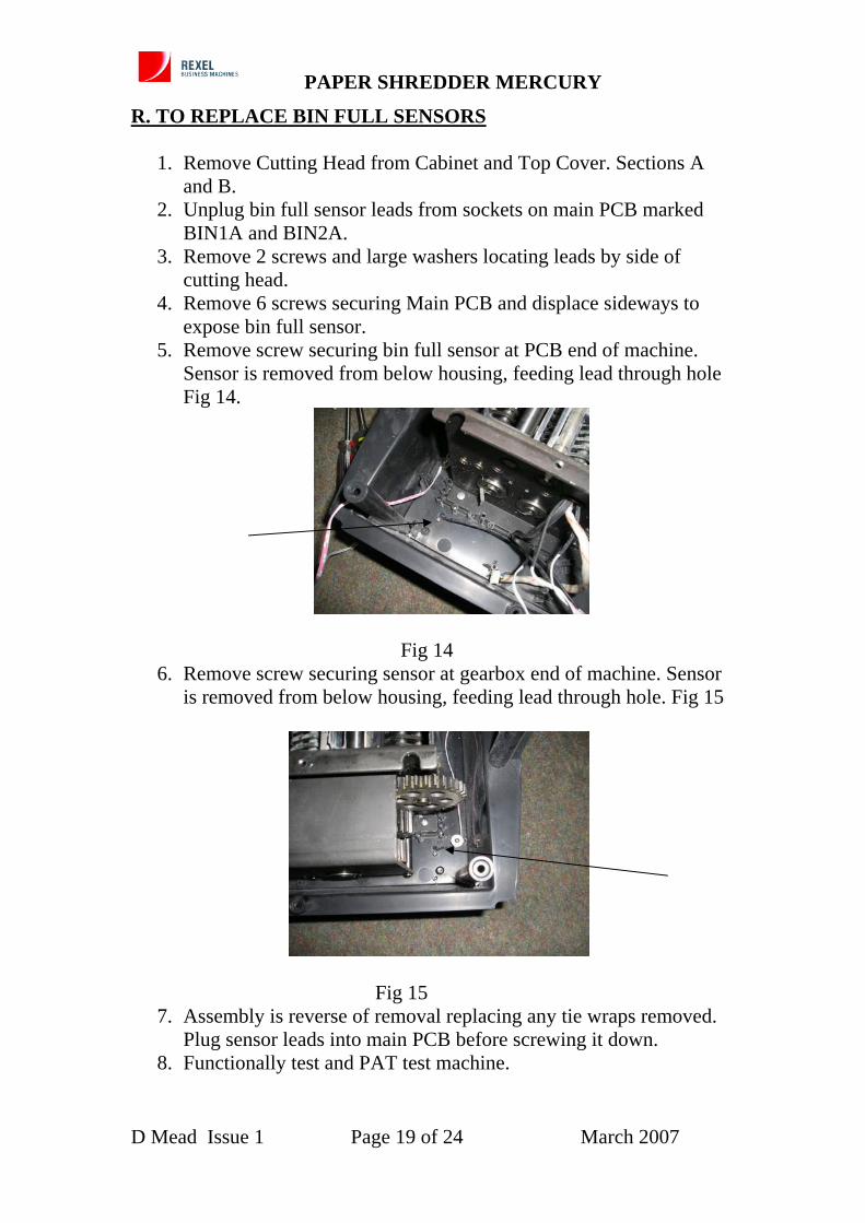
R. TO REPLACE BIN FULL SENSORS
1. Remove Cutting Head from Cabinet and Top Cover. Sections A and B.
2. Unplug bin full sensor leads from sockets on main PCB marked BIN1A and BIN2A.
3. Remove 2 screws and large washers locating leads by side of cutting head.
4. Remove 6 screws securing Main PCB and displace sideways to expose bin full sensor.
5. Remove screw securing bin full sensor at PCB end of machine. Sensor is removed from below housing, feeding lead through hole Fig 14.
Fig 14
6. Remove screw securing sensor at gearbox end of machine. Sensor is removed from below housing, feeding lead through hole. Fig 15
Fig 15
7. Assembly is reverse of removal replacing any tie wraps removed. Plug sensor leads into main PCB before screwing it down.