Paper Technology Journal 10 News from the Divisions: Republic Paperboard Company – the world’s first paper machine with two gap formers. Wet End Process™ – new technology solutions around the paper machine wet end. Bauernfeind PM 1 – strengthening of Frohnleiten mill. Sirius – the online wind-up system. Corporate news: Voith São Paulo, Brazil. Paper Culture: Festas do Povo, Campo Maior.
Transcript
Paper Technology Journal
10
News from the Divisions:Republic Paperboard Company – the world’s first paper machine withtwo gap formers.
Wet End Process™ – new technologysolutions around the paper machinewet end.
Republic Paperboard Company – the world’s first paper machine with two gap formers 2
Stock Preparation: Wet End Process™ – New technology solutions around the paper machine wet end 7
Stock Preparation: Screening of recovered paper stockfor the production of graphic papers 12
Paper Machines: DuoFormer TQv – a new twin wire former 17
Paper Machines: DuoCleaner – the optimal fabric and felt cleaning system 22
Paper Machines: Kehl PM 6 – a new production line for laminating papers 26
Paper Machines: Dongying Huatai successful start up 30
Paper Machines: Zhuhai BM 2 started up 2 weeks ahead of schedule 32
Paper Machines: Bauernfeind PM 1 – strengthening of Frohnleiten mill 36
Paper Machines: TissueFlex – first application in America 40
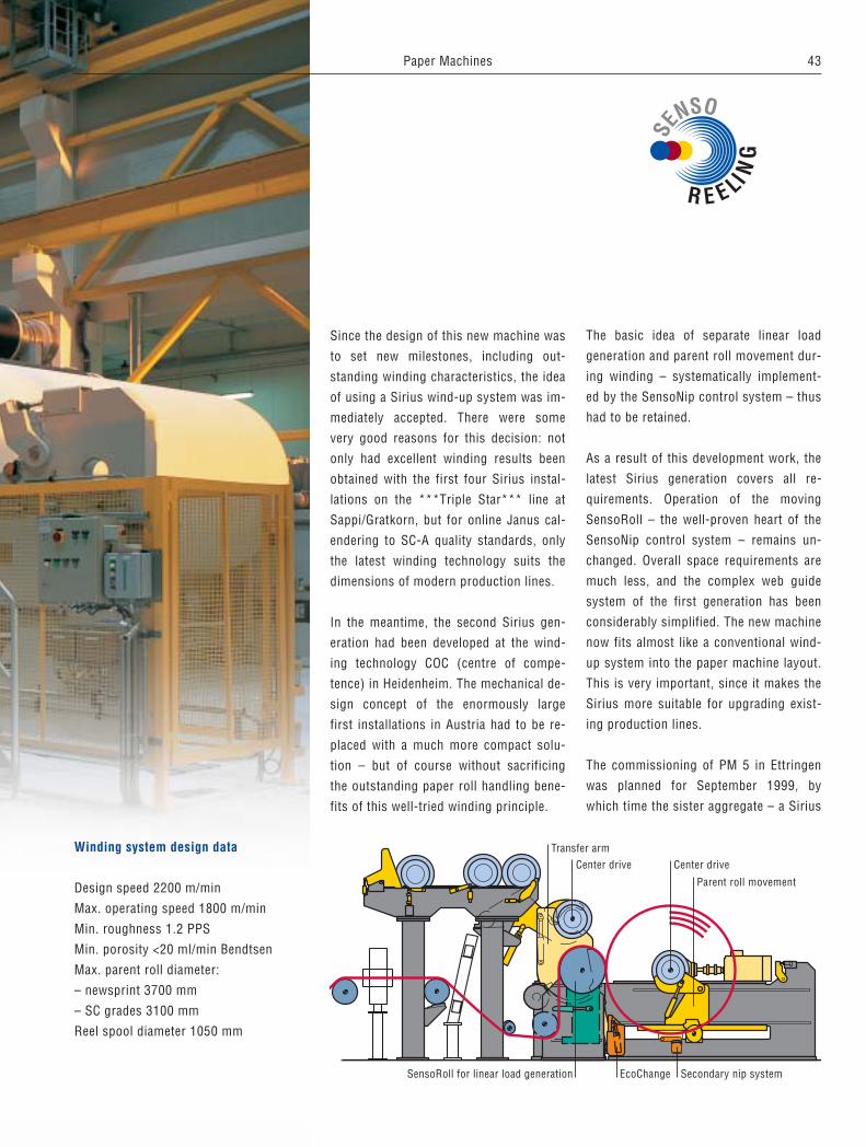
Paper Machines: Sirius – the online wind-up system 42
Finishing: “A look behind the scenes” – preparations for the start-up of the Janus MK 2 for Schongau PM 9 45
Service: Partnership with papermaker leads to innovative solution 49
Paper Machines: Process technology – meeting current and future demands on system suppliers 52
CORPORATE NEWS
Voith São Paulo, Brazil 55
Stickies summit in Washington, D.C. 59
PAPER CULTURE
“Festas do Povo”, Campo Maior 60
Frontispiece: Republic Paperboard Company – the first parent rolls produced on the new machine with two gap formers.
1
Dear Customer, dear Reader,
We have pleasure in introducing you to Issue No. 10 of our popular twogether PaperTechnology Journal for the pulp and paper industry. The positive feedback we continueto receive from around the world encourages us to keep up the high standard ofarticles published in this truly international communications tool.
We are fully aware that the consolidation trend among our customers has not ceasedand this continues to have a damping effect on worldwide order placement for com-plete new production lines, particularly in the graphic papers section. On the otherhand, demand for rebuilds aimed at product quality improvements, especially for finish-ing equipment, remains buoyant. Our Board and Packaging Paper operations also showa healthy level of activity, pointing to a record booking level for the current businessyear. Similarly, we can see positive trends in demand for our stock preparationproduct lines.
In the meantime, our leading position in shoe press technology has been furthersubstantiated with the order for the 200th NipcoFlex Shoe Press since market intro-duction of this innovative product.
The second calender generation of our Janus Concept line – Mark II –, has beensuccessfully introduced to the paper industry and the performance of our Janus tech-nology in Port Hawkesbury, Canada, has been stabilized, providing a significant contri-bution to the record-breaking production levels for SC-A grades on PM 2 at this mill.
Successful integration of the Scapa Plc roll covering line into our Service Divisionconfirms the merits of this decision to add to the overall competence of our systemsupplier approach. Our customers likewise benefit from the close link betweenVoith Fabrics (now incorporating the complete range of Scapa’s fabrics activities) andVoith Sulzer’s development of new paper machine processes and components.
In short, we see an exciting time ahead of us and we have full confidence in the con-tinueing fine performance of the industry we serve.
Yours sincerely,
Hans Mülleron behalf of the Voith Sulzer Paper Technology Team
Hans Müller,President and CEOVoith Sulzer Paper Technology
2
The author:Christoph Merckens,Paper MachinesBoard and Packaging
Republic Paperboard Company – the world’s first paper machine withtwo gap formers
The Republic Group Incorporated –
a company looking to the future
Headquartered in Hutchinson, Kansas,
Republic Group Incorporated (NYSE:
RGC), the parent Company of Republic
Paperboard Company, is comprised of
three business segments, namely paper-
board manufacturing, gypsum wallboard
manufacturing and paper recycling. The
production of gypsum-grade paperboard
and gypsum wallboard has always been
On November 27, 1999, Republic
Paperboard Company, Lawton,
Oklahoma, USA, brought about a
revolution in paper manufacturing:
A new gypsum-grade paperboard
machine was brought on-line –
the world’s first paper machine with
two gap formers. This milestone in
board and packaging paper production
illustrates the technological leadership
and innovative spirit of Voith Sulzer
Paper Technology.
3
perboard in the USA. To achieve this
goal, they were interested in new, innova-
tive technologies, some of which were al-
ready being used successfully in Europe.
Lawton, Oklahoma was chosen as the site
of the paper mill due to its central loca-
tion in relation to both Republic’s internal
and external customers. A large part of
the production is sold to other domestic
gypsum wallboard manufacturers through
long-term delivery contracts.
Gypsum-grade paperboard as a product
Gypsum wallboard is made of a gypsum
core and two sheets of paper, accounting
for both strength and appearance of the
wallboard. The two-component creamface
(white top layer and gray filler) is used
for the face of the gypsum wallboard;
whereas, one-component gray board is
used for the back (grayback). Both prod-
ucts can be manufactured on Lawton’s
PM 1. The requirements to be met by both
grades are complex; however, the most
decisive properties are high strength, a
hydrophobic top layer (achieved by siz-
ing) to shield the product against humid-
ity from outside and a hydrophilic back
layer to achieve optimum bonding be-
tween gypsum and paperboard. Current-
ly, basis weights range between 190 g/m2
(39 lbs/MSF) and 200 g/m2 (41 lbs/MSF),
but are to be reduced to 180 g/m2
(37 lbs/MSF) in the years to come. Apart
from the two gypsum-grade paperboard
products, the mill can produce a variety
of other products. The machine is de-
signed to produce basis weights from
127 to 244 g/m2 (26 to 50 lbs/MSF).
An ambitious project is taking its course
Republic Paperboard’s vision was clearly
defined right from the start – to double
core businesses of Republic. To offer
gypsum-grade paperboard also in the
lower basis weight range, it was decided
to supplement the Company’s paperboard
mills located in Hutchinson, Kansas;
Commerce City – Denver, Colorado; and
Halltown, West Virginia, with a new
greenfield paperboard mill. In a press re-
lease, Phil Simpson, Republic's Chairman
and President, declared that the group
had set a goal to become a leading manu-
facturer of lightweight gypsum-grade pa-
Fig. 1 and 2: Republic Paperboard Company inLawton, Oklahoma, USA.
1
2
4
the group’s paper production with a new,
high quality, low cost production plant.
In the summer of 1997, Voith Sulzer was
contacted as one of several renowned
suppliers to work on a project for the
manufacture of three or four-layer gyp-
sum-grade paperboard. One of the cus-
tomer's basic requirements was to use
only components that had already been
tried and tested. Therefore, a design with
three fourdrinier wires was developed for
the wire section, which was being tested
on the Voith Sulzer test paper machine
Stock preparation
The stock preparation system was deliv-
ered and started up by Voith Sulzer Paper
Technology, Appleton, Wisconsin, USA. It
consists of two lines, one for the white
top layer of the creamface and another
one for the gray filler and backlayers of
creamface and all layers of the grayback.
Fig. 3: Pulper in the stock preparation.
Fig. 4: Scheme KM 1.
Fig. 5: Final section of KM.
Fig. 6: DuoFormer Top with ModuleJet.
3
5
4
for board and packaging papers at
Ravensburg, Germany.
At the same time, the Voith Sulzer project
team presented a configuration with the
two gap formers especially developed for
board and packaging papers, Duo-
Former™ Base and DuoFormer™ Top,
which seemed to be ideally suited for the
production of gypsum-grade paperboard.
Both gap formers were installed on the
test paper machine at the time when the
tests for the fourdrinier wire design were
performed. The customer became inter-
ested in running tests with the gap form-
ers as well, which then prompted another
series of tests. These extensive field tests
determined that fitting the new machine
with gap formers was the correct choice.
The dedicated teamwork of Republic
Paperboard and the Voith Sulzer team
helped to create the trendsetting design
for the world’s first paper machine with
two gap formers.
On February 19, 1998, Voith Sulzer Paper
Technology finally obtained the order to
deliver two complete stock preparation
lines, the paper machine and a slitter-
winder.
5
To achieve excellent results in slushing
and cleaning of the recycled paper, the
design for both lines was developed in
close cooperation with the customer and
on the basis of tests performed at
Ravensburg, Germany, and Appleton,
Wisconsin.
The white line is fed with primarily un-
printed white grades of paper and has a
capacity of 240 tons/day. It consists of a
continuous pulper, as well as pressure
screening, cleaning and refining systems.
The gray line is primarily fed with
ONP and OCC and has a daily capacity of
745 tons. After the continuous pulper,
the stock is supplied to a coarse and fine
screening system. The cleaner system for
separating heavy and lightweight contam-
inants is followed by fractionation and re-
fining equipment for short and long fiber
components. In addition, Voith Sulzer’s
scope of supply included Meri rejects
handling units, as well as Andritz refiners
and disk filters.
Paper machine: two gap formers and
other state-of-the-art components
The paperboard machine’s former design
sets new standards for the board and
6
6
packaging paper machines of the new
millennium. In the future, not only in
gypsum-grade paperboard production,
but also for many other liner and board
grades, two or more gap formers will be
used in one machine.
Two gap formers were used in the wire
section on the Republic machine. The
first former, DuoFormer™ Base, produces
a top layer. The second former, the
world’s first DuoFormer™ Top, forms a
bottom layer. The most important advan-
tage of the gap formers is to achieve
good formation within a wide MD/CD
ratio range. Compared to the fourdrinier
wire, higher consistencies can be run
while obtaining a comparable formation
and the bond strength is better, which
makes spraying starch unnecessary. To
achieve optimum CD profiles, the head-
box of the DuoFormer Top is fitted with a
ModuleJet™ dilution water control. And
last, but not least, little space is required
for a gap former, compared to alternative
designs.
The Tandem NipcoFlex™ press (a double
shoe press) was chosen to obtain maxi-
mum strength values while ensuring high
porosity at the same time. Additional
benefits of the press configuration are
high runnability and simple transfer. The
entire dryer section is two-tiered, the
fabrics of the first two dryer groups are
fitted with Voith Sulzer DuoCleaners™
for cleaning. – After the dryer section, a
hard-nip calender with heated bottom roll
and EcoNip top roll is installed, and final-
ly, a cooling unit is installed consisting of
four cylinders which helps to keep the
temperature on the reel operator-friendly.
The paper is wound on a horizontal reel
with reel spool magazine.
The paper machine was delivered and
started up by Republic and Voith Sulzer
Papiermaschinen AG, St. Poelten, Austria.
Installation and start-up
Fluor Daniel of Greenville, South Carolina,
was selected as general contractor for in-
stalling the complete plant. Excavation
work started in late June 1998, and as
early as January 1999, the first paper
machine foundation plates were installed.
In March 1999, the installation of the pa-
per machine and the stock preparation
plant was started under the supervision
of Voith Sulzer personnel. The electro-me-
chanical testing of the entire plant, first of
the stock preparation system and then of
the paper machine, was started in August.
The common goal of completing such an
innovative project required rapid and
constructive cooperation between the
highly motivated teams of Voith Sulzer,
Republic Paperboard and Fluor Daniel.
The machine is running
Finally, in November 1999, the time had
come: “stock on wire” was attained on
November 21. Six days later, the entire
paper machine was put into operation
(paper on the reel). Start-up can be
described best by a short comment of
Republic Paperboard’s most important
customer in Lawton: “Don't change any-
thing!” Already, the second roll of gypsum-
grade paperboard was salable quality!
Voith Sulzer Paper Technology and
Republic Paperboard are proud to have
set this milestone in paper production
together. The thanks and congratulations
of the Voith Sulzer team go to the staff of
Republic Paperboard who have put their
trust in us, which was absolutely needed
for putting an entirely new concept of
such dimensions into practice.
Facts and figuresWorking width: 4,000 mm (161 inches)Maximum roll diameter: 3,000 mmAnnual production: 220,000 tOperating speed: 762 m/min (2,500 fpm)Products:Gypsum-grade paperboard:
Creamface 180-200 g/m2
Grayback 170-190 g/m2
Packaging grades: 127-244 g/m2
7
Main functions in the Wet End Process™
The Wet End Process™ mainly consists
of three subsystems: the approach flow,
fibre recovery, and broke handling. These
subsystems in turn can be broken down
into clearly defined functions (Fig. 1). At
the beginning of the approach flow, the
various furnish components are mixed in
the right proportions. Apart from a cor-
rect solids ratio of the individual compo-
nents, the papermaker also needs to
ensure a constant stock consistency.
Return stock flow from broke treatment,
the extraction of sweetener stock and
filter thick stock return flows all have to
be taken into account, – in conventionally
arranged systems by arranging the mix-
ing and machine chests in series.
The authors:Dr. Michael Schwarz, Anton Gmeiner, Stock Preparation
Both for graphic grades and packaging
papers, the trend towards higher oper-
ating speeds continues unabated. At
the same time, the dilemma of higher
quality at lower cost is being solved by
using a broader mixture of furnish
components.
In this context, a decisive role is played
by the process technology around the
wet end of the paper machine. The Wet
End Process™ (WEP) plays a critical
role in paper production due to the
immediate vicinity of the sheet forma-
tion zone and the complex interfaces
with other process subsystems.
Wet End Process™ –new technology solutions around the paper machine wet end
StoffaufbereitungN e w s F R O M T H E D I V I S I O N S
8
1
The subsequent dilution with whitewater
plays a key role, since from this mixing
stage onwards, the stock is in a pressur-
ized closed-circuit loop right up to the
headbox slice. In other words, any pres-
sure fluctuation or change in stock con-
sistency immediately affects headbox
mass flow, and therefore the basis weight
of the finished paper product.
The approach flow directly before the
headbox is an extremely sensitive area
where it is essential to keep all parame-
ters stable. Pressure variations are prop-
agated in the pipework at sonic speed
through to the headbox, where mass flow
at the slice outlet changes simultaneously
across the entire machine width. This
only influences the MD, and not the CD
basis weight profile. On the other hand,
stock consistency deviations affect both
the CD and MD basis weight profiles be-
cause they show up staggered across the
machine width depending on flow veloci-
ty in the pipework and headbox distribu-
tor. All machines and design measures in
the approach flow should be judged on
their ability to stabilize stock consistency
and pressure.
On all high speed paper machines and for
certain speciality grades, mechanical
deaeration is undertaken together with
stock cleaning in the LC range, although
cleaning at this point is not mandatory.
Screening is installed immediately before
the headbox, usually mainly as a policing
measure.
In the former and press sections, space
available for water removal is steadily de-
creasing with modern new paper ma-
chines. Special attention must therefore
be paid to optimum whitewater collection.
Whitewater I surplus is passed to fibre
recovery together with whitewater II,
while heavily contaminated flow compo-
nents and the press filtrate are directly
cleaned by microflotation. Broke treat-
ment has to accommodate the various
broke flows (coated or uncoated), and it
has to offer sufficient storage capacity.
Voith Sulzer has critically investigated
the functionality of all WEP subsystems
and redesigned them where necessary.
The result is a “toolbox” of optimum sub-
system designs on a modular basis,
enabling customized, favourably priced
system solutions for all individual needs.
Some of the less familiar components as
well as certain new developments in the
approach flow are presented here.
Furnish mixing
Apart from high installation costs, con-
ventional stock mixing in mixing and ma-
chine chests has a further serious draw-
back. The large stock volumes result in
control system deadtimes which delay
stabilization (Fig. 2). With smaller vol-
umes and more efficient mixing, the
ComMix™ system ensures more stable
mixing and consistency than convention-
al mixing and machine chest systems.
As shown in Fig. 3, the individual fresh
stock flows, together with broke and
thick stock from disk filtering, are fed
into a horizontally arranged mixing tube.
By tangentially staggered feeding, the
kinetic flow energy of the individual stock
components is efficiently converted into
mixing energy.
Broketreatment
Fiberrecovery
Whitewaterhandling
Hea
dbox
Form
er/p
ress
sect
ion
Mix
ing
offu
rnis
hco
mpo
nent
s
Dilu
tion
with
whi
tew
ater
Scre
enin
g
Dea
erat
ion
Clea
ning
Fig. 1: Functions in the Wet End Process™.
9Stock Preparation
Whitewater
BackflowTo fan pump
Overflow fromdeaeration
Thick stock
Subsequent static mixing elements are
recommended where the ratio of furnish
components fluctuates widely.
Stock mixing and whitewater
Conventional system technology is to
store whitewater in a generously dimen-
sioned tower, with fresh stock entering at
the bottom for mixing (Fig. 4).
HydroMix™ is a new development which
has no storage capacity, but functions
purely as a hydraulic flow mixing system.
The individual flows enter and are imme-
diately passed on. Exhaustive trials have
enabled us to accurately define the opti-
mum conditions for efficient stock mixing.
Fig. 5 shows a HydroMix™ installation
operating for the last 2 years on an LWC
machine. Since this rebuild and elimina-
tion of the whitewater tower, the mill has
reported significantly reduced MD/CD
profile variation coefficients.
Retention agent dosage
Given today’s wide variety of furnishes
and fillers, a correct choice of retention
agent, and in particular correct mixing,
are decisively important. To reduce costs
and optimize effectiveness, additives
need to be mixed in quickly and distrib-
uted evenly. We have therefore carefully
investigated the hydrodynamics involved
in the mixing process. The present state
of technology is to introduce the reten-
ComMix™:Conventional:
Mixing chest Machine chest
Sweetener stock
2 3
Conventional: HydroMix™:
Stock StockCleanerpump
Cleanerpump
4 5
Fig. 2: Furnish mixingConventional:� Large volumes� Slow control response� 2 pumpsComMix™:� Volume reduction by 70%� Improved control strategy (filler, consistency)� 1 pump.
Fig. 3: Furnish mixing in the ComMix™.
Fig. 4: Stock mixing with whitewaterConventional:� Large volumes� Good mixingHydroMix™:� Volume reduction by 80%� Space saving installation� Fast control response � Good mixing.
Fig. 5: HydroMix™.
10
tion agent against the direction of stock
flow, although introduction in the flow
direction has also been recommended in
recent times (Fig. 6). Extensive tests
were carried out to establish the condi-
tions for optimum mixing kinetics. The
mixing results were evaluated by digital
photographic analysis (auto-correlation of
the mixing image).
As expected, a high velocity differential
between retention agent and stock flow is
essential for the efficiency, and in partic-
ular, for the speed of mixing. The trials
also showed significantly better mixing
results with introduction of the retention
agent against the direction of stock flow.
Whitewater handling
Voith Sulzer has developed a family of
new components for efficient collection
and removal of the large volumes of
whitewater in the restricted spaces avail-
able in modern paper machines. The
components can be used individually or
in combination, thus ensuring reliable
management of all process water flows.
VortexBreaker™
Where a horizontal flow is diverted into a
vertical flow, the invariable result is vor-
tex formation and risk of air entrainment.
Installing flow equalizers to remove al-
ready formed vortices is costly, and in
many cases impossible due to local con-
Fig. 6: Mixing trials for retention aids.
Fig. 7: Whitewater handling with the VortexBreaker™.
Fig. 8: Whitewater handling with HydroPipes™.
6Parallel flow:
Autocorrelation of mixing effect:
3 x D
l = 0.47 l = 0.89Ø
Counterflow:
3 x D
Ø
Ø Ø
7VortexBreaker™:
Air entrainment in tray outlet,vortex is generated
No air entrainment in trayoutlet, no vortex
Conventional:
8Conventional: HydroPipes™:
PM
WW WW
PM
No air entrainmentAir entrainmentby waterfall effect
11Stock Preparation
Housing
Flowdistributionbasket
Vacuumconnection
Inlet
ditions. By installing a suitable lamellar
grid just below the surface, vortex forma-
tion is prevented before it can occur in
the first place (Fig. 7).
HydroPipes™
The collection of whitewater on the drive
side of the paper machine often involves
considerable height differences (Fig. 8).
If no costly measures are taken – such as
LIC controlled flow retention – the resul-
tant waterfall effect can generate uncon-
trolled hydraulic flow conditions with air
entrainment causing system distur-
bances. This can be avoided by designing
the whitewater tray with an inclined side-
wall and installing staggered drainage
pipes so that any height difference can be
accommodated.
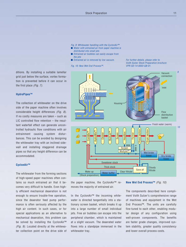
CyclonAir™
The whitewater from the forming sections
of high-speed paper machines often con-
tains so much entrained air that it be-
comes very difficult to handle. Even high-
ly efficient mechanical deaeration is not
enough to ensure trouble-free operation,
since the deaerator feed pump perfor-
mance is often seriously affected by the
high air content. In such cases, or for
special applications as an alternative to
mechanical deaeration, this problem can
be solved by installing the CyclonAir™
(Fig. 9). Located directly at the whitewa-
ter collection point on the drive side of
the paper machine, the CyclonAir™ re-
moves the majority of entrained air.
In the CyclonAir™ the incoming white-
water is directed tangentially into a sta-
tionary screen basket, which breaks it up
into a large number of small individual
jets. Free air bubbles can escape into the
peripheral chamber, which is maintained
at a slight vacuum. The deaerated water
flows into a standpipe immersed in the
whitewater tray.
New Wet End Process™ (Fig. 10)
The components described here compli-
ment Voith Sulzer’s comprehensive range
of machines and equipment in the Wet
End Process™. The units are carefully
fine-tuned to each other, enabling modu-
lar design of any configuration using
well-proven components. The benefits
are faster grade changes, improved sys-
tem stability, greater quality consistency
and lower overall process costs.
9
Clear filtrate
Cloudyfiltrate
(Stock preparation)Make up
Thick stock
Sweetener stock
Fresh water (warm)
Dry broketower
Water buffer
Wet broketower
Hea
dbox
Form
er
Scre
en
Mul
tiJet
™
Clea
ner
Hyd
roM
ix™
Save all
Dry
erse
ctio
n
Com
Mix
™
Screen
Pres
sse
ctio
n
MultiJet™
WW I
WW
II
10
Fig. 9: Whitewater handling with the CyclonAir™� Water with entrained air from paper machine is
distributed into small jets� Entrained air bubbles can easily escape from
the jets� Entrained air is removed by low vacuum.
Fig. 10: New Wet End Process™.
For further details, please refer to Voith Sulzer Stock Preparation brochureVPR-SD-14-0003-GB-01.
12
paper: Using recovered paper meanshaving to solve the stickies problem!
Although screening stickies is no easytask due to their inherent characteristics,removal can be facilitated under certainconditions. These include the choice ofsuitable screens, screen baskets and ro-tor design (see twogether Journal No. 1and 4.). However, no measures on theirown can guarantee optimum screening,since acceptable stickies removal is notpossible with single screening systemsor machines. Recovered paper process-ing therefore consists of several subsys-tems, of which screening is by far themost important. Fig. 1 shows a typicalrecovered paper processing line. Holescreening removes problematic contami-nants to protect the downstream systemsand to make the stock suitable for fineslot screening. Although every effort ismade to exploit all potential for optimumstickies removal, stickies removal rates(by number) in hole screening are ratherlow. An efficiency as high as 50 % for thecomplete hole screening system would be
The author:Reimund RieneckerStock Preparation
Since graphic papers are bulk gradesproduced on high-speed machines,operating economics have a highpriority. For the higher quality grades,however, additional aspects must beconsidered. Although primary fibres arestill preferred here, a certain content ofrecovered paper is not a bad idea sinceit brings advantages on the paper ma-chine. This presents no problems withtoday’s advanced technology for pro-cessing recovered paper, but specificcriteria must still be met. Only whitepaper grades should be used and theyshould have a sufficiently high qualitypotential, and be available in suitablylarge quantities. The only reliablesource meeting these needs is house-hold collection. Recovered paper is,however, very different from primaryfibres. It contains contaminants virtu-ally unknown in primary stock and thesecan decisively influence production,and the end product itself. The mainproblem is stickies, which occur wher-ever recovered paper is used. The fol-lowing statement is therefore funda-mental in the screening of recovered
Screening of recovered paper stock for theproduction of graphic papers
1
Newsprintstandardimproved
SC papersstandardimproved
LWC papersstandardimproved
++
++
++
++
++
++
++
++
++
++
++
++
++
++
++
++
++
+
+
++
++
++
++
++
+
++
++
++
++
++
++
++
++
++
++
++
++
++
++
++
++
+
++
+
+
++
++
+++
++
++
++
++
++
++
++
LCSc
reen
ing
HW
Clea
ning
Ref
inin
g
Pres
s
Blea
chin
gII
Dis
pers
ion
II
Pres
s
Dis
kfil
ter
Flot
atio
nII
Blea
chin
gI
Dis
pers
ion
I
Pres
s
Dis
kfil
ter
LCSc
reen
ing
//
LWCl
eani
ng
HW
Clea
ning
Flot
atio
nI
MC
Scre
enin
g//
MC
Scre
enin
gø
Prot
ecto
rsy
stem
Pulp
ing
13Stock Preparation
100 500 1000 3000 10000Stickies diameter [mm]
100 500 1000 3000 10000Stickies diameter [mm]
1
0
Stic
kies
no.c
once
ntra
tion
Size
clas
sra
nge
Effic
ienc
yh
[%]
(Num
ber)
Stickies size distribution(Inlet to hole screening)
Stickies removal as afunction of particle size
1
0
1kg
• mm
[]
Measured using TAPPI Test Method T 277 pm-99
2
0
Effic
ienc
y%
50
100
Overallefficiency %
MC hole screening MC slot screening LC slot screening
000
33.333.333.3
53.833.353.8
76.8366.776.83
MCø+MC//+LC//MCø+LC//MCø+MC//
Residual stickies (area)5.46.2
23.2
0 %+ 15 %+ 330 %
0.25
0.2
0.15
ø1.4 0.25 0.15
0.15
0.15
ø1.4
ø1.4
1 2 3 4 5
94.693.876.83
Flot
atio
n
Clea
ning
3
an extremely good result. Screening effi-ciency is critically dependent on variousfactors, above all on the stickies size dis-tribution (Fig. 2). On the left-hand side, atypical stickies distribution according tosize shows that the stickies count in-creases asymptotically with reducing par-ticle size, a trend which extends beyondthe measurability limit. This indicatesthat many stickies pass through the rela-tively large screen holes, and also cannotbe detected by conventional laboratorymeasuring methods. It is therefore diffi-cult to make an objective assessment.The right-hand side of the graph summa-rizes the average stickies removal effi-ciencies of several screening systems (allwith a hole diameter of 1.4 mm) as afunction of stickies size. Removal effi-ciency falls off to a minimum of 10 to30 % as particle size reduces to about750 µm, and it remains constant until themeasuring limit of 150 µm is reached.Efficiencies of over 70 % therefore cannotbe expected, since most stickies are be-low 600 to 700 µm in size. It is thereforeadvisable not to demand too high aremoval efficiency, since this just leadsto reducing the stickies size below themeasuring limit rather than removingthem. This apparent good efficiency pro-vides enviable removal rates but onlymakes things more difficult for the down-stream systems. The next process stageis usually slotted screening.
Reducing slot size means more and morefine sand is retained. This is virtually im-possible to remove in the MC range andleads to increased system wear. Stickiesremoval is also more difficult in the MCrange (see twogether Journal No. 4). Theusual practice in modern plants is to
Fig. 1: Schematic arrangement of recovered fibrestock preparation for various graphic papergrades.
Fig. 2: Hole pre-screening in DIP systems.Left: Normal stickies size distribution in the inletRight: Stickies removal as a function of particlesize.
Fig. 3: Comparison of stickies removal withvarious screening system concepts.
14
install LC cleaning after deinking andthis is then followed by fine slot screen-ing with today’s standard slot width of0.15 mm, although the trend is towardseven finer slot widths.
Voith Sulzer had the rare chance of ex-amining various screening systems in aDIP line (schematic arrangement shownin Fig. 3) for graphic papers made from100 % recovered paper. Their direct in-fluence on paper machine runnability wasassessed. The system was originally op-erated exclusively with MC hole and slot-ted screening. An LC slotted screeningstage was added at a later date. Stickiesremoval then improved from 76.8 % toan overall system screening efficiency of94.6 %, and sheet breaks on the papermachine were reduced from about threeper day to only about one in six weeks.This drastic improvement underlines theneed for a well-designed and sensiblyoperated LC slotted screening stage.
How far can slot widths be reduced?
Today, slot widths of 0.15 mm are stan-dard practice, but particularly for im-proved qualities, requirements are muchmore demanding and the trend is there-fore towards even finer slots. Here thereare limits. Fig. 4 shows a cross-sectionthrough a C-bar® basket with a slot widthof 0.1 mm, and on the same scale, fibresand shives from a deinking line for pro-cessing wood-containing recovered papergrades. Clearly, even normal TMP fibresor fibre bundles can only pass throughsuch fine slots when they are forcedthrough. This means accepting eitherlarge rejects quantities and/or a reduction
Fig. 4: Scale size comparison of fibres and shivesfrom wood-containing DIP stock with the cross-section of a 0.1 mm C-bar® slotted screen basket.
Fig. 5: Effect of slot width changes on systemoperating reliability in a DIP fine screeningsystem.
Fig. 6: Scale size comparison of scanningelectron microscope photographs of calenderedpaper made from various furnishes with thecross-section of a 0.1 mm C-bar® slotted screenbasket.
Fig. 7: Comparison of standard and A/B screeningconcept (single stage).
Fig. 8: Comparison of 3-stage forward-flowconcepts with different stickies size distributions.System A: Standard arrangement with simplescreening in all three stages.System B: First stage with simple screening,second and third stages with A/B arrangement.
6
0.1 mm
Groundwood(stoneground)
TMP fornewsprint
DIP from householdcollection
1mm
in stickies size. The tolerance between re-quired efficiency and operating reliabilityis very narrow with fine slots, particularlyon wood-containing grades, as shown inthe following mill example.
A fine screening system (Fig. 5) consist-ing of five machines in three stages, orig-inally with 0.15 mm slot widths (systemon the left), was systematically convertedto finer slots. One can easily see howeven the slightest modifications canheavily influence operating reliability ofthe overall screening system. In themeantime, this plant has now been com-pletely fitted with 0.12 mm slotted bas-kets and some changes have also beenmade in the loop layout as well. Thisarrangement also operates completelytrouble-free like the arrangement beforeit. Although these measures increasedslot velocity, the measurable number ofstickies has been reduced by 32 %, andthe stickies area by 51 %. With wood-freefurnishes, the use of ultra-fine slots isless critical. This is illustrated in a DIPline for wood-free copy paper production,where a complete fine screening systemhas been installed. All screen basketshave 0.10 mm slots. This four-stagesystem with the first two stages arrangedfor forward flow is extremely effectiveand has been in trouble-free operation forseveral years.
SC and LWC papers
SC papers require the highest possiblesurface quality, in particular smoothness.Prerequisite for high surface quality is afine-grade stock, free of shives and fibrebundles. If recovered fibres are used,
16
problems may arise due to the contami-nant content. For this reason, today’s re-cycled fibre content hardly ever exceeds30 % for top quality grades. With LWCgrades, these requirements are not quiteso extreme. On the one hand, the R14fraction should not exceed certain limitsdue to the risk of fibre rising when thesheet is re-wetted during coating. On theother hand, R30 fibres are desirable forstrength reasons. This situation is bestillustrated by the comparison in Fig. 6which shows a cross-section through a0.1 mm C-bar® screen basket and samescale microphotographs of calendered labsheets made from various stocks. Clear-ly, the TMP fibre size in particular cangreatly exceed the slot width. Such fibreshave little chance of passing throughsuch fine slots without considerable help.
Although such fine slots have afavourable influence on stickies removal– and manufacturing C-bar® baskets withslots under 0.1 mm is no problem today– slot widths do have their natural limit.This limit is determined by a practicalcompromise between throughput and ac-ceptable conditions. Narrow slots aloneare no general cure for stickies problems.Another possibility is the A/B arrange-ment.
A/B arrangement for improvingefficiency
An A/B arrangement consists of two ormore screens in series, where acceptsfrom the first machine A are screenedagain in machine B. Stickies removal effi-ciencies and R30 yields with standardand A/B arrangements are compared in
the following for various slot widths(Fig. 7). Individual efficiency values foreach size class are used instead of over-all average efficiency values. An overallrejects rate of 25 % is assumed, i.e. 15 %in the A stage and 12 % in the B stage ofan A/B arrangement.
For the single screen with 0.12 mm slotwidth, mill data reveals an average stick-ies removal efficiency of 85.7 % with anR30 yield of 56 %. In the second case,the A/B arrangement with 0.12 mm slotwidths increases the stickies removal ef-ficiency to 96 % and reduces R30 yield to48 %. The third example shows a stickiesremoval efficiency of almost 92 % withthe A/B arrangement and 0.15 mm slotwidths. The R30 yield here is around56 %. In other words, we have a signifi-cantly higher stickies removal efficiencythan with the single machine, yet roughlythe same R30 yield. If the A/B slot widthis increased to 0.20 mm, the averagestickies removal efficiency is 81.5 % withan R30 yield of 64 %. These examplesshow that even with a larger slot widthof, for instance, 0,15 mm, the stickiesremoval efficiency can be significantly in-creased for the same long-fibre yield.
In another example the effect of theabove arrangement variants when usingseveral stages was investigated. Removalefficiency is based here on two stickiessize classes. To calculate the overallstickies removal efficiency in each case, ahigher efficiency is taken for the largeparticles and a lower efficiency for thesmaller ones. This method was used forcomparing two 3-stage screening sys-tems (Fig. 8). System “A” consists of“simple screening” with only an “A” ma-
chine in each stage, while system “B” hasan A/B layout in the second and thirdstages. Both systems were computedtwice, using different stickies size com-positions each time: in the first case80 % large and 20 % small stickies, andin the second case vice-versa. In systemA, 26 % rejects were assumed in the firststage, 25 % in the second stage and 30 %in the third stage. This gives an overallsubstance loss of 1.95 %. In system B,20 % rejects were assumed for all stages,the resultant substance loss being2.59 %. With a stickies size distributionof 80 % large and 20 % small, system Ahas a stickies removal efficiency of 78 %compared with 81 % for system B. Theseexamples show that with an above-aver-age proportion of large stickies, the influ-ence of system arrangement on stickiesremoval efficiency is only slight. But witha predominant proportion of small stick-ies, the picture is completely different. Inthis case removal efficiency in system Afalls steeply from 78 to 70 %, while insystem B it falls only by one percent from81 to 80 %.
In other words, an A/B arrangement pro-vides a high removal efficiency even if alarge number of smaller particles are pre-sent, and, above all the arrangementensures a high quality consistency. Thisis therefore a good way to attain opti-mum removal efficiencies.
For further details, please refer to Voith Sulzer Stock Preparation brochurest.SD.05.0004.GB.01
17Paper Machines
ing gap created by the top and bottom
wire. The initial drainage starts on the
forming roll. The forming roll promotes
retention and enables a far less critical
headbox jet positioning in comparison to
a pure blade former. The roll is followed
by the well known D-Section – a blade
section – which delivers excellent forma-
tion. A wet suction box further increases
the dry content before the web arrives at
the couch roll. The wet box, placed in the
top wire loop, ensures that almost no
free water is left on the top wire. Water
splashing at the couch roll is reduced to
a minimum and thus means a big save-all
pan at the drive roll (top wire) is not
needed. The large couch roll wrap and a
high vacuum flat suction box deliver a
good dry content of the paper web before
the web enters the press section.
Due to the vertical arrangement of the
forming elements, the white water han-
dling is most simple. Suction deflectors
and weirs can be avoided.
The authors:Hans Moser,Volker Schmidt-Rohr,Dr. Joachim Grabscheid,Werner Eckl,Paper Machines Graphic
Many paper properties are determined
at the former section. For this reason
forming sections are critically important
in papermaking. But today’s highly de-
manding markets want more than excel-
lent paper properties. Simultaneously,
productivity and expenses for a forming
section must be handled with great
care. Productivity is strongly affected by
machine speed and web width.
If productivity and paper quality is fore-
most then the DuoFormer TQv is first
choice. The DuoFormer TQv represents
the latest generation of Voith Sulzer gap
formers. The former can be applied for
all mass papers.
DuoFormer TQv (Fig. 1)
The former comprises the well-known roll
and blade forming concept. A ModuleJet
headbox delivers the stock into the form-
DuoFormer TQv – a new twin wire former
1
18
2
DuoFormer TQ v for different paper
grades (Fig. 2)
The stock for wood-containing grades
has normally high drainage resistance and
low shear resistance. For those grades,
the TQv is designed with a large forming
roll wrap angle and no forming blades.
However, for wood-containing grades,
based on a slow stock with a significant
amount of long fibre required for good
Fig. 1: DuoFormer TQv.
Fig. 2: DuoFormer TQv and different furnish.
Fig. 3: D-Section and drainage down the table.
strength properties, forming blades are
recommended. Stock for wood-free
grades drains quickly and shows high
shear resistance. The wrap angle is small
in order to allow enough water into the
blade forming section. For excellent for-
mation up to three blades are installed.
Additional blades will result in a minor
improvement of formation however, si-
multaneously wire wear will be increased
markedly. Indeed too many blades are a
disadvantage.
DuoFormer TQv, major benefits
Paper properties
A curved suction box and forming blades
(counter blades), also known as D-Sec-
tion, are a prerequisite for excellent for-
mation (Fig. 3, left hand side). The box
has two chambers and vacuum is applied
for controlling sheet structure in Z-direc-
tion. The forming blades are loaded
against the suction box by a pneumatic
system and they are well protected from
white water thrown off at high speed at
the forming roll .
Hydrodynamic forces increase with high
machine speed. For efficient water
removal and good sheet properties, the
blade geometry should be perfect. In or-
der to install or remove ceramic blades,
conventional T-bar holders require a cer-
tain clearance. The clearance leads to
faulty geometry; i.e. the blades do not
skim the water off properly. To correct
this at high-speed machines, a composite
blade section replaces single blades. All
single ceramic blades are embedded in a
reinforcement structure which forms a
single cover of blades with high preci-
sion. This cover is connected to the suc-
tion box by a clamping mechanism.
Fig. 3, right hand side illustrates the
flows down the table. All flows are based
on the headbox flow, which is set to
100%. De-watering is almost equal
through the top and bottom wires which
DuoFormer TQvwood-containing
DuoFormer TQvwood-free
3Compositebladesection
Flow distribution
36 %
8 %
4 %1 %
6 %
4 %
38 %
100 %
49 %48 %Total Total
19Paper Machines
results in a symmetric sheet. About 48%
of water is drained through the top wire
and 49% through the bottom wire.
Approximately 74% of the drainage oc-
curs at the forming roll. This means 36%
passes through the bottom wire and 38%
passes through the top wire into the void
volume of the forming roll. The curved
suction box and the forming blades re-
move about 12% of the water. The wet
suction box further increases the dry
content. Approximately 6% of the water
is removed at this drainage element. With
the large couch roll wrap, 4% of the wa-
ter is removed. Finally, entering the press
section, the high vacuum flat suction box
removes a further 1% of the water.
Dry content before pick up
A large couch roll wrap plus a Hi-Vac-Box
are very efficient tools to improve the dry
content before the web enters the press
section (Fig. 4, left hand side). A box,
running at 60 kPa, boosts the dry content
from 14% to 18%. This excellent im-
provement in dry content was measured
on SC-paper. A second couch roll would
be much less effective.
Wire life
The life depends heavily on the number
of edges in the loop (Fig. 4, right hand
side). In this example fast newsprint
machines, running with DIP, have been
investigated. Every ceramic blade has two
edges, one upstream and one down-
Dry content as a function of dwell time Wire cycles as a function of edges
15
10
5
0Wir
ecy
cles
(num
ber
•106
)
Ceramic edges (number)4 26 32 54 62 110
Roll-Blade-GapformerNewsprintDIP furnish
Dry
cont
ent[
%]
Dwell time [ms]0 8 16 24 32 40
20
4
16
12
8
0
35KP
a
65KP
a
60KP
a
Couch roll High-vacuum-
box
4
5
Forming roll change Couch roll change 6
Fig. 4: Dry content and wire life.
Fig. 5: Wire change.
Fig. 6: Maintainance.
20
stream tip. Both edges create wire wear.
The number of blades has an significant
impact on wire life or, in other words,
wire cycles. In order to optimise wire life
for the DuoFormer TQv, the number of
blades in the top wire and bottom wire
loops has been reduced to a minimum.
Wire change
The top and bottom wire loop structures
are fully cantilevered. In order to prepare
the former for wire change the breast roll
is moved away from the forming roll
(Fig. 5). A mechanism rotates the top
wire drive roll and the wet suction box,
along with the forming blades, away from
the wire run. The curved suction box is
moved back towards the press section.
These measures provide free access to
the top and bottom wire. Both stretcher
systems are adjusted to minimum wire
length. Replacing old wires with new is a
most simple procedure due to the shape
Fig. 7: Inspection of forming zone.
Fig. 8: Graphic paper, distribution of formationand DuoFormer TQv performance.
Fig. 3: Cleaning results on a forming fabric, press felt and dryer fabric (from top to bottom).Left: before, right: after.
3
1918
14
3
to 1995 1996 1997 1998
Num
ber
ofun
itscu
mul
ated
200
150
100
50
1999
25Paper Machines
� Less mist generation and fines
deposits
� Less formation interference and paper
sheet damage by stickies removal
� Uniform drainage thanks to perma-
nently clean fabric.
Press section benefits
� Less tearing thanks to constant clean
felt surfaces
� Good CD profile thanks to intensive
and uniform cleaning
� Long felt service life thanks to less
deposits of abrasive fillers and less felt
hair losses.
Dryer section benefits
Fig. 4 shows definitive cleaning results
on dry section felts and fabrics. The air
permeability of a new fabric is compared
here with that of a conventionally cleaned
fabric and one continuously cleaned by
the DuoCleaner. The uniformly high air
permeability of the dryer section felts and
fabrics, and the removal of stickies, re-
sult in the following benefits:
� Less tearing
� Less sheet perforation
� Lower energy costs thanks to im-
proved sheet evaporation
� Uniform CD profile
� Outstanding effectiveness of web
stabilizers
� No shutdowns required for cleaning,
no chemicals.
Furthermore, fabric life is often extended
by a factor of 4 to 5. Fig. 5 shows a typi-
cal example of this.
With conventional cleaning systems, this
fabric had to be changed every 5 months
on average. The DuoCleaner extended the
service life to more than 20 months.
Prospects
Today more than 250 DuoCleaners world-
wide are improving the production effi-
ciency of paper machines including tis-
sue, pulp and board. DuoCleaner sales
figures since market launch in 1995 are
shown in Fig. 6.
It goes without saying that all new Voith
Sulzer Paper Technology machines are
equipped with DuoCleaners, but the suc-
cess of the DuoCleaner so far is mainly
due to rebuilds and retrofits. With ongo-
ing development and extension of the ap-
plication range, the DuoCleaner will con-
tinue to improve papermaking efficiency
and cost-effectiveness.
Fig. 4: DuoCleaner – Perlen PM 5.Second dryer group top double tier, operatingtime 11 months.
Fig. 5: Fabric lifetimes at Dachau PM 8.
Fig. 6: DuoCleaner sales figures.
4
6
Perm
eabi
lity
[CFM
]
100%
16%
85%
280 CFMnew
fabric
238 CFMfabric cleaned
withDuoCleaner
44 CFMcontaminated
fabric
5
without DuoCleaner with DuoCleaner
Mon
th20
15
10
5
26
ization and expansive development,
August Koehler AG regards itself today as
“a world company with a family charac-
ter”. This description aptly fits the com-
pany structure and culture: largely fami-
ly-owned and run, with close customer
contact, high reliability and quality, ongo-
ing success through specialization, and
open to innovative developments.
Innovative paper applications these days
include the increased use of special-pur-
pose laminating papers for laminating
chipboard surfaces in the furniture and
The author:Dieter Blaschka,Paper MachinesGraphic
In April 1999 August Koehler AG, Ober-
kirch/Germany ordered from Voith Sulzer
Paper Technology an additional produc-
tion line for laminating papers. Founded
in 1807, August Koehler AG has expand-
ed in the meantime into a papermaking
group still headquartered at the original
location of Oberkirch in the Black Forest,
but with four other mills in Germany at
Kehl, Ettlingen, Bensheim and Greiz.
Products range from carbon copy papers,
thermo and fine papers, to recycling
board and special papers as well as wall-
paper base. With this successful special-
Kehl PM 6 –a new production line for laminating papers
27
1
construction industries. The paper is ro-
togravure colour printed with a wide vari-
ety of imitation wood graining, masonry
textures or other patterns, then impreg-
nated with resin and pressed onto the
chipboard surface.
The paper properties required for this ap-
plication are exacting: excellent printabili-
ty and dimensional stability, yet at the
same time good ink absorption and uni-
form resin penetration. On top of this,
high strength and good wet tensile
strength are required to stand up to the
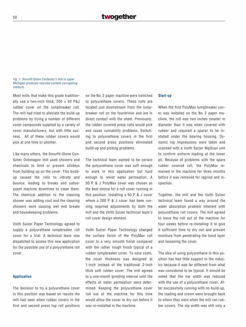
Fig. 1: The Kehl plant of August Koehler AG,showing the new PM 6 building in the leftforeground.
printing and impregnation processes, as
well as high opacity for adequate cover-
ing of the base material. Although lami-
nating paper production needs only a rel-
atively modest machine width for the
subsequent processing requirements, the
stringent quality criteria involved require
modern high-speed paper machine tech-
nology. The new production line for the
Kehl mill, which already has a Voith ma-
chine for carbon copy and thermo pa-
pers, is the first complete new production
unit to be built in Germany for laminating
papers.
The production concept and integration
into the existing Kehl plant buildings and
infrastructure is the result of close team-
work between the project engineering
groups of August Koehler AG and Voith
Sulzer Paper Technology. Scope of sup-
ply for Voith Sulzer Paper Technology is
as follows:
Stock preparation
� Pulper charging, including virgin pulp
bale conveying system
� Pulper for virgin pulp
1034
K1
K2
28
� High density cleaning
� Deflaking
� Low density cleaning
� MultiScreen fine screening
Dry broke preparation
� Pulper charging system
� Slat conveyor with roll slitting and
weighing
� High consistency pulping
� High density cleaning
� Deflaking
� EconoMix mixing propellers
Broke pulpers
� Couch broke
� Press broke
� Dry broke
Paper machine
� MasterJet F
headbox with ModuleJet for thermal sta-
bility during operation and Constatherm
water circulation system for use during
production stoppages.
Together with the Profilmatic cross ma-
chine profile control system, these en-
sure ideal conditions for optimum cross
machine basis weight and fibre orienta-
tion profiles.
Any pulsations coming from the approach
flow system are dampened directly ahead
of the headbox using our well-proven
pulsation damper.
The distributor and turbulence inserts are
easily accessible for cleaning purposes
by swinging off the headbox back wall.
� Sheet formation
Fourdrinier with dandy roll and drainage
elements (designed and supplied by
August Koehler).
– Suction couch roll
– DuoShake high-intensity shake unit for
optimum formation. DuoShake has no
reaction forces so that foundations are
simplified since they only have to carry
the weight of the shake unit.
DuoShake shake units have been operat-
ing successfully for a number of years in
Koehler’s Oberkirch and Ettlingen mills.
� Press section
3-roll Nipco press with separate pick-up,
followed by a Nipco straight-through
press.
This concept has the following advan-
tages:
– Uniform drainage on both sides
– Uniform sheet consolidation on both
sides
– High dry content
A press of this type has been operating at
the Koehler mill in Ettlingen since 1998.
� Dryer section
Particular attention has been paid to a
reliable web guidance for low-strength
webs and high operating speeds. The
2
29
first two TopDuoRun dryer groups are
therefore equipped with vacuum rolls and
DuoStabilizers. Web stabilizers ensure
smooth running of the sheet in the re-
maining dryer groups. A cooling cylinder
group incorporating high performance
cooling cylinders is located at the end of
the dryer section.
A rope-free feed-up system ensures fast
feeding up of the sheet, thus helping to
maximize overall machine efficiency. The
steam, condensate and cooling systems
precisely control web drying behaviour
and web temperature.
� Janus calender
This consists of a vertical five-roll
arrangement. Trials with laminating pa-
pers at the Voith Sulzer test facility in
Krefeld/Germany confirmed that this cal-
endering concept is ideal for optimum
printing results. A disengageable rope
system was selected for reliable sheet
transfer through the Janus calender to
the reel drum.
� Reel-up
with reel-spool magazine for automated
spool transport and changing.
A combination of perforated reel drum
and winding tension control ensures per-
fectly wound reels from the core out.
� Roll wrapping machine
Type: Twister Combi 1
The advantage of this concept is that only
one width of wrapping paper roll is
required for various reel widths. A wrap-
ping machine of this type is already in
operation at the Oberkirch mill.
� Engineering
– Machine and system engineering
– Basic and detailed engineering for
process, paper machine and auxiliaries
– Basic and detailed engineering for the
control and instrumentation systems.
The topping out ceremony for the new
PM 6 building was held on September 3,
1999. Paper machine erection started in
January 2000, and commissioning is
planned for August 2000.
Klaus and Wolfgang Furler, board direc-
tors of August Koehler AG, commented
on their decision to place the order with
Voith Sulzer Paper Technology:
“This was certainly the right decision.
The project is running very smoothly,
and above all the technological optimiza-
tion teamwork is outstanding.”
3
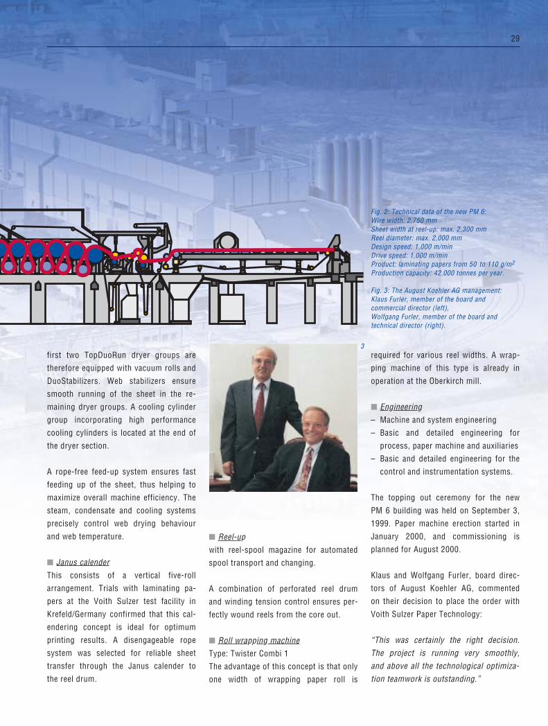
Fig. 2: Technical data of the new PM 6:Wire width: 2,750 mmSheet width at reel-up: max. 2,300 mmReel diameter: max. 2,000 mmDesign speed: 1,000 m/minDrive speed: 1,000 m/minProduct: laminating papers from 50 to 110 g/m2
Production capacity: 42,000 tonnes per year.
Fig. 3: The August Koehler AG management:Klaus Furler, member of the board andcommercial director (left), Wolfgang Furler, member of the board andtechnical director (right).
30
the-art ModuleJet headbox – computer
controlled with the Profilmatic M from
Voith Sulzer Automation, this headbox
controls a perfect basis weight profile by
means of 42-Control zones.
Voith Sulzer Automation delivered the
whole QCS system including
� the complete headbox control function,
� the CD caliper control actuator
ThermaJet with 34-zones,
� two AdvantagePlus frames, each
comprising sensors for basis weight,
moisture and caliper, and
� the brandnew technology: the InfoPac
Papermachine Information System,
which allows papermakers as well as
mill management rapid access to, and
The author:Frank Opletal, Voith SulzerPaper Technology, BeijingCentral Representative Office
Clear blue sky in northern Shandong
Province – close to the scenic view of
the Yellow River mouth where it flows
into the Beihai sea a huge new expan-
sion project is underway. Approaching
the vicinity of the mill the new impres-
sive power generation plant and right
after this the new papermachine
building are beaming into once eye.
As reported already in our twogether No. 7
under the topic “Speedcoater for Chinese
market leadership” the Shandong Huatai
Group in Dongying, did not stop to invest
in Top technology in buying a speed-
coater and a softnip calender only. To stay
ahead with technology and paper quality
and be a leader to let the Chinese paper
industry prosper, Director Li Jianhua (see
separate comment from him), decided to
go even further and purchase a state-of-
Dongying Huatai successful start up
1
31Paper Machines
4
3
2
powerful analysis of paper quality and
machine performance. Moreover, the
function of the archives also allows for
storage of quality datafor the mill’s
internal quality control system. This is
the first such system to be in opera-
tion in China.
All in all the installation and commission-
ing went very well, even the very cold
winter brought some obstacles to cir-
cumsail. Using 70% pulp made from rice
straw and 30% bleached market pulp, the
new paper created is first class LWC,
coated simultaneously with a speedcoater
of the newest generation. In the future
Reed pulp will be used instead of the
bleached market pulp. The final finishing
touches are performed with a new two
nip Ecosoft modular calender.
Fig. 1: Paper machine Dongying Huatai.
Fig. 2: ModuleJet stock preparation.
Fig. 3: Speedcoater.
Fig. 4: Ecosoft calender.
Li Jian Hua,
President Dongying Huatai
To face up the challenge of world market
competition after China enters into the
world trade organisation, Chinese paper
mills have to strengthen themselves with
input of modern advanced paper technol-
ogy equipment, to produce the high grade
value added products. With this vision in
mind, we decided to purchase from Voith
Sulzer the most advanced equipment. We
are very much satisfied with the machin-
ery supplied by Voith Sulzer and we are
looking forward to co-operate with each
other on other projects in the future.
32
Zhuhai S.E.Z. Hongta Renheng Co. Ltd.can be regarded as the direct success ofboard machine No. 1, which was alsosupplied by Voith Sulzer St. Poelten. Atthat time, the main structural parts camefrom Liaoyang Paper Machinery Works.BM 1 was taken on stream in 1993. Thesefacts, combined with the leading positionof the Voith Sulzer Board and PackagingPaper Division worldwide and in China,resulted in the delivery of the fourth fullyimported board machine to China. WhileBM 1 has been run over its design capac-ity by almost 50% for quite a long time,
The authors:Robert Adolf Dokter, Paper MachinesBoard and Packaging;Frank Opletal, Voith SulzerPaper Technology BeijingCentral Representative Office
The board mill of Hongta Renheng Co.is located rather close to the downtownarea of Zhuhai City, which is, as localssay, a “bright pearl among Chinesecities” regarding quality of life andenvironmental surroundings. Its out-standing geographical location directlyat the South China Sea and its proximityto Macao and Hongkong make it notonly the ideal place for a vacation, butalso a strategically perfect businesslocation.
Zhuhai S.E.Z. Hongta Renheng Co. Ltd.is the leading supplier of cigarette-boxcardboard in the Chinese market, and ispart of Hongta Renheng, the joint venturebetween Yunnan Hongta Industrial Co. Ltd.and Hongkong Renheng Investment Co.
The Yunnan Hongta Group comprises50 enterprises, with tobacco being thelargest and core business, and thus it isthe third largest manufacturer of ciga-rettes worldwide. Other businesses in-clude power generation, paper & boardmanufacturing, printing, construction ma-terials, banking and insurances as well aslight trucks.
On February 25th, 1998, Zhuhai S.E.Z.Hongta Renheng Co. Ltd. and VoithSulzer Papiermaschinen AG St. Poeltensigned the contract for the delivery ofboard machine No. 2 during a customer’svisit to St. Poelten in the presence ofhigh-ranking political officials from thePeople’s Republic of China. The projectwas entirely financed by Zhuhai S.E.Z.Hongta Renheng Co. Ltd.
The follow-up order for the supply of an-other new board production line from
Zhuhai BM 2started up 2 weeks ahead of schedule
33
2
1
the new BM 2 is currently steamingahead from one record quality productionto the other. This being the case, thequality parameters have been reachedalready in early March 2000 – merely twomonths after going into continuous pro-duction. The taking-over certificate wassoon signed thereafter.
By making every possible effort to seethe project through within the shortestpossible time, the civil constructionworks started on August 1st, 1998 withthe first pile being driven into the earth.
Fig. 1: Board machine 2.
Fig. 2: Press section with Flexonip press.
34
Zhao Wanli, General Manager Zhuhai
Hongta Renheng Paper Co., Ltd.
We have been enjoying a relationship of
good cooperation with Voith Sulzer Paper
Technology for several years, based on
mutual trust and assistance. After com-
paring many suppliers, we chose Voith
Sulzer for board machine No. 1 (BM 1).
Our choice proved to be wise and correct
in practice. This machine has been run-
ning to our full satisfaction since it was
put into operation, and its machine
speed reached 270 m/min 1 1/2 years
ago, far exceeding its design speed of
250 m/min. The key point is that the
quality of the coated board produced by
BM 1 has reached international first-rate
level: our products are welcomed to the
Chinese market for top-quality board and
demand for it exceeds supply. The suc-
cess of BM 1 has set new technological
standards, which positively influence
3
product quality and help to strengthen
our market position.
Voith Sulzer was again chosen as the
supplier for the key equipment (board
machine) and began to execute the BM 2
project in 1998. BM 2 has an untrimmed
working width of 4200 mm, a design
speed of 600 m/min and produces
150,000 tons/year. Construction of BM 2
started in August 1998, and start-up took
place in December 1999. As early as
March 2000, board was produced, which
fully met the quality requirements. Our
qualified engineering personnel and the
other technical personnel, together with
Voith Sulzer Paper Technology’s experts,
contributed to the success of this project.
The BM 2 project, including design, man-
ufacturing, tests, installation and start-
up, was completed, achieving high quali-
ty and efficiency. The high design speed
of BM 2 caused a great sensation among
the board producers in China. We believe
that choosing Voith Sulzer as the sup-
plier for BM 2 will again prove to be a
wise decision.
We are making plans for a BM 3 project,
which will increase the production ca-
pacity by 300,000 tons, and hope to con-
tinue our good cooperation with Voith
Sulzer.
Zhuhai Hongta Renheng would like to
take this opportunity to express their
heartfelt thanks to Voith Sulzer’s man-
agement and all engineering, technical
and service personnel involved in BM 1
and/or BM 2 projects.
35Paper Machines
Fig. 3: On-line coating equipment.
Fig. 4: Speedsizer.
Fig. 5: Horizontal reel.
Fig. 6: Winder.
4By February 1999, the installation of theboard machine foundation plates couldbe finished so that the first componentsof the dryer section were installed earlyin March 1999. A highly qualified team ofengineers assigned by the customer,locally hired construction firms with ex-cellent previous experiences in installingpaper machines and a team of VoithSulzer experts were teaming up to meetthe tight time schedules and high qualityrequirements during the installationperiod. Thus, no-load tests could bestarted by September 1999. On December15th, 1999, the first board was producedat the horizontal reel after a very well or-ganised commissioning period. – Twoweeks ahead of the contractual schedule,Voith Sulzer delivered the complete mul-ti-fourdrinier board machine, includingshoe press, on-line coaters and finishingequipment like the slitter winder, as wellas key equipment for all board machine-related auxiliary equipment.
The plant engineering was performedin close co-operation with the ChangshaDesign Institute, which had been nomi-
nated by the customer to provide theoverall engineering scope. This co-opera-tion had been proven successful on sev-eral other projects in China before.
The layout design of the board machineallows the customer to produce cigarette-box cardboard and liquid packagingboard accounting for a yearly gross pro-duction of 150,000 tons. As raw materialsources, Zhuhai S.E.Z. Hongta RenhengCo. Ltd. prefers to buy NBKP and BCTMPfrom North American suppliers, whileLBKP is mostly purchased from Brasilian,Indonesian and Thai pulp producers.
Currently, the production still covers thelocal South Chinese market, like theprovinces of Guangdong, Yunnan, Hunan,Hubei and Sichuan. But Zhuhai S.E.Z.Hongta Renheng Co. Ltd.’s future salesstrategy is to ship high-class board alsoto other countries in South East Asia.
Voith Sulzer Paper Technology offers itsheartfelt congratulations to the manage-ment of Zhuhai S.E.Z. Hongta RenhengCo. Ltd.
5
6
36
Roman Bauernfeind Verpackungswerk AGwas founded in 1945. In a former combfactory, they started converting solidboard, and in 1963, corrugated board. In1972, they started producing corrugatedboard, and in 1984, when Frohnleiten Pa-per Mill was acquired, paper productionwas started. Today, Roman BauernfeindPapierfabriken AG produces corrugatedboard base papers at 5 different loca-tions: Frohnleiten (Austria), Raubling(Germany), Niedergösgen, Moudon(Switzerland) and Monza (Italy).
More than 500,000 tons/year of high-grade packaging paper from 100% recy-cled furnish are produced on these ma-chines. Currently, 400,000 tons/year areconverted at the group’s locations in Ger-many, Belgium, Austria, Italy, Poland andChina. The majority of exports from Aus-
The author:Petra Resch,Paper MachinesBoard and Packaging
After a major rebuild, PM 1 at Frohn-leiten mill of Roman Bauernfeind AGwas successfully put into operationin November 1999. The aim of therebuild was to boost PM 1 production,tripling the output of corrugated boardbase papers from 100% recycledfurnish.
The rebuild was accomplished in twophases. The first upgrade in the sum-mer of 1998 included the installationof a state-of-the-art shoe press.
With the second phase being complet-ed, including a renewal of the approachflow system and paper machine asfar as the winder, the entire PM is nowdesigned for a speed of 1000 m/min.
Bauernfeind PM 1 –Strengthening of Frohnleiten mill
37Paper Machines
2
1
tria goes to Germany, Czech Republic andBelgium.
The export share is about 60%. RomanBauernfeind AG is the market leader inAustria and the second largest supplier inEurope for pre-print products. In addi-tion, Bauernfeind is one of the largestprivately owned paper and packaginggroups in Europe.
After the successful rebuild of the presssection in the summer of 1998, the fol-low-up order for the rebuild of the othercomponents of PM 1 was placed byRoman Bauernfeind AG with Voith Sulzerin February 1999. Through these two up-grades, the paper machine was almostcompletely renewed, presently operatingat 800 m/min working speed. The entirerebuild was completed in a record time of
Fig. 1: Roman Bauernfeind AG, Frohnleiten mill.
Fig. 2: Stock preparation MasterJet F/B.
38
approximately 11 weeks with productionstops of less than three weeks.
The main goal of the rebuild was to setnew standards in paper production. AtFrohnleiten mill, most of the corrugatingmedium is produced by PM 1. Especiallyin this product range, a new trend hasbecome apparent in recent years. Thegeneral tendency towards thinner fluteprofiles requires lower basis weights. Aproduct with thinner flutes will bettermeet the market requirements such asimproved printability. Although a lowerbasis weight results in a lower specific
output with constant speed, this is morethan compensated by increasing PM 1’soutput. After the rebuild, its output in-creased to 300 tons/day of corrugatingmedium and 330 tons/day of wrappingpaper.
The following basic components wererenewed: The wet end was equipped witha MasterJet headbox (refer to twogetherJournal No. 8, page 24). A special featureof this latest member of the headbox fam-ily is that no heating is required to ensurea parallel slice. Due to the quality demandsmade on the CD profile, precise adjusting
units with oblong spindles are used tocontrol the CD basis weight profile.
To optimally utilize the structural condi-tions and at the same time find an opti-mum solution to meet the high qualitystandards, a decision was made in favorof the topwire former DuoFormer™ D.The advantages of this two-sideddrainage are an improvement of forma-tion and a shorter drainage section com-pared to a conventional fourdrinier.
The press section rebuild was completedin the summer of 1998. The installation
3
Technical data of PM 1 after the rebuild:Wire width: 2,950 mmMaximum production speed: 800 m/minPaper grades: Corrugating medium: 90-180 g/m2
Wrapping paper: 90-180 g/m2
Maximum capacity: 330 tons/day.
3
39Paper Machines
of a NipcoFlex™ press was the first steptowards an increase in PM 1 output,improving the dryness with constantquality.
The first group of the pre-dryer sectionhas been designed as a serpentine groupwith DuoStabilizers™ – the remaininggroups and the after-dryer section are ofconventional two-tier design. DuoStabi-lizers™ and web stabilizers ensure asmooth web run. A ropeless transfersystem is installed in the pre- and after-dryer sections.
A transfer doctor takes the tail off the lastpress, and the transfer foil directs it intothe dryer section. The blowpipes installedat the blowing doctors ensure ropelesstail transfer. With speed and productionincreases expected, the size press andthe reel also had to be redimensioned. Inthe reel area, the building had to be ex-tended, but remained unchanged in thewire section area. This extension wasnecessary to allow for the required dryingcapacity and the installation of the newwinder.
As installation work was completed ontime, paper was on the reel again twodays ahead of the scheduled start-update. Just hours after start-up, salablepaper was produced. The hybrid formerimproved formation by about 50%.
After a short optimizing phase, the de-sired strength increase and the reductionof the 2-sigma values of the basis weightprofile have already met the expectations.Within the first three months, wrappingpaper was produced at the design speedof 800 m/min.
Fig. 3: DuoFormer D.
Fig. 4: Final section.
Fig. 5: Mill owner Roman Bauernfeind and Otto Heissenberger, executive vice presidentof Voith Sulzer Papiermaschinen AG, St. Pölten.
4
5
1
40
of today’s technology, the same speed
can be achieved using only one shoe
press against the Yankee.
The entire machine rebuild was complet-
ed over a 6 1/2 day shutdown period in
which several other services were execut-
ed, including the Yankee dryer grinding.
The installation of the TissueFlex™ itself
took approximately four days.
The objectives of the rebuild, and the
basis for return on investment were an
operating cost reduction, saving 5% of
fiber, and product quality improvement.
Now, after a short period of approximate-
ly two months, this new technology has
reached all the objectives that were set.
The author:Ronaldo Parucker,Voith S.A. São Paulo
Late in January 2000, the first commer-
cial application of the TissueFlex in the
Americas and the second in the world
started up successfully. The TissueFlex
technology consists of a shoe press
against the Yankee dryer surface.
This equipment was installed in Mogi
das Cruzes, São Paulo, Brazil, at
Companhia Melhoramentos de São
Paulo, a long-established Brazilian
tissue manufacturer.
Prior to the installation, the machine
operated with two presses against the
Yankee, at speeds limited to approxi-
mately 1,600 m/min. With the application
TissueFlex –first application in America
41Paper Machines
4After the TissueFlex™ start-up, a bulk in-
crease of approximately 20% was real-
ized, and paper softness was greatly im-
proved. After some analysis, it was also
noted that fiber reduction would possibly
be even greater than 5%. The conversion
of toilet paper, now being manufactured
with the new TissueFlex™ technology,
presented no problems. The other main
product of this tissue machine is napkin.
The company now achieves the same
package size with 50 units, compared to
a package of 60 units before the rebuild.
Even with a basis toilet paper weight re-
duction of approximately 5%, the diame-
ter of the converted paper roll increased
approximately 2.5%.
Fig. 1: General view of TissueFlex installation atCompanhia Melhoramentos de São Paulo, Brazil.
Fig. 2: TissueFlex technology for tissue.
Fig. 3: Tissue machine Melhoramentos Papéis S.A.
Fig. 4: TissueFlex control panel.
As to production itself, Melhoramentos
points out that after the felt compaction
the machine already reaches the same
production as before the rebuild. How-
ever, they feel that the next target will be
to determine the best felt for this new
technology, since the felt compaction
time significantly increased.
There was a small increase in steam con-
sumption with the production of papers
with a higher basis weight. However, it is
believed that this consumption will be
significantly reduced through the use of
the right felt. Consideration has to be giv-
en to the fact that the machine now oper-
ates with only one press, compared to
the two presses against the Yankee be-
fore the rebuild. The consumption of
water, vacuum and fuel for the hood re-
mained unchanged. Total drive power
consumption remained the same, the
suction roll and the Yankee consume
more power, but, on the other hand,
there is no longer any blind drilled press.
Another important issue at Melhoramen-
tos is that some items requiring frequent
maintenance were eliminated, such as the
suction press and the rolls for the second
press. Previously, the press rolls had to
be exchanged or serviced every four
months, due to problems with the rubber
covers (plugged shell drillings, total cov-
er loss etc.), causing long down time,
which resulted in lost production. With
the installation of the new TissueFlex™
technology, the mill feels that these prob-
lems have now been solved.
Even considering the relatively small
amount of time that the mill has been us-
ing the new TissueFlex™ technology,
Melhoramentos is pleased, since the
transition phase, as well as the learning
curve was very short and the objectives
set for this rebuild were fully achieved.
TissueFlex pressingdirectly against theyankee
NipcoFlex roll
Suction roll
2
3
42
The author:Oliver Rudolph,Paper MachinesGraphic
Sirius –the online wind-up system
When the first Janus calender was
retrofitted to PM 4 at the Ettringen
paper mill, Gebrüder Lang started con-
sidering the online concept for natural
papers well before installing PM 5.
Transfer armCenter drive
Secondary nip systemEcoChange
Parent roll movement
SensoRoll for linear load generation
Center drive
43Paper Machines
Since the design of this new machine was
to set new milestones, including out-
standing winding characteristics, the idea
of using a Sirius wind-up system was im-
mediately accepted. There were some
very good reasons for this decision: not
only had excellent winding results been
obtained with the first four Sirius instal-
lations on the ***Triple Star*** line at
Sappi/Gratkorn, but for online Janus cal-
endering to SC-A quality standards, only
the latest winding technology suits the
dimensions of modern production lines.
In the meantime, the second Sirius gen-
eration had been developed at the wind-
ing technology COC (centre of compe-
tence) in Heidenheim. The mechanical de-
sign concept of the enormously large
first installations in Austria had to be re-
placed with a much more compact solu-
tion – but of course without sacrificing
the outstanding paper roll handling bene-
fits of this well-tried winding principle.
The basic idea of separate linear load
generation and parent roll movement dur-
ing winding – systematically implement-
ed by the SensoNip control system – thus
had to be retained.
As a result of this development work, the
latest Sirius generation covers all re-
quirements. Operation of the moving
SensoRoll – the well-proven heart of the
SensoNip control system – remains un-
changed. Overall space requirements are
much less, and the complex web guide
system of the first generation has been
considerably simplified. The new machine
now fits almost like a conventional wind-
up system into the paper machine layout.
This is very important, since it makes the
Sirius more suitable for upgrading exist-
ing production lines.
The commissioning of PM 5 in Ettringen
was planned for September 1999, by
which time the sister aggregate – a Sirius
Winding system design data
Design speed 2200 m/min
Max. operating speed 1800 m/min
Min. roughness 1.2 PPS
Min. porosity <20 ml/min Bendtsen
Max. parent roll diameter:
– newsprint 3700 mm
– SC grades 3100 mm
Reel spool diameter 1050 mm
44
with identical layout geometry – was also
to be commissioned on the new PM 3 at
Papierfabrik Palm in Eltmann. This pro-
duces newsprint from 100% recovered
paper, and winding requirements with
finished rolls 3700 mm in diameter are
just as demanding (and perhaps record-
breaking) as on PM 5 in Ettringen.
It was quite a challenge for Voith Sulzer
Paper Technology to commission these
two almost identical aggregates – both of
them the first of their kind – but the risk
was more than rewarded. Both the Ettrin-
gen and Eltmann units showed perfect
winding results, even with the imperfect
sheet quality to be expected during initial
operation.
The two highly motivated commissioning
teams, supported from time to time by
our development and technology people,
exchanged findings to ensure a really ef-
ficient optimization phase thanks to the
resultant synergy effect.
Only shortly after startup, the winding
parameters of web tension, centre drive
torque and – most important of all – lin-
ear load control were finalized for the
respective operating conditions of the
two paper machines.
Both installations enable comparatively
low free web tension. And as is well
known, low web tension at the end of the
line generally reduces the risk of web
breaks – thus boosting the overall pro-
duction efficiency.
Tail transfer in the area of the new Sirius
wind-up system was quickly optimized.
Even prior to actual commissioning, the
Fibron vacuum tapes and related transfer
equipment were pre-adjusted. Using a
specially developed unwind, the tail
transfer procedure was thoroughly test-
ed. As a result, only slight adjustments
were required for production startup
when the paper machine was finally
ready.
These are two examples of the efficient
procedures – including new experiences
– which led to the high reliability of the
Sirius wind-up system in such a short
time. Commissioning of both the new
Sirius installations was completed with-
out a hitch – thanks to careful prepara-
tions and the know-how gained from
exhaustive testing on our R&D facility
with all kinds of paper.
Both installations meet all requirements
for residual slab and winding quality,
thus increasing the efficiency of their re-
spective production lines.
Operating experience so far with the
Sirius wind-up system is very encourag-
ing with regard to further development.
Future applications will cover nearly all
main paper grades such as LWC, copying
papers, liner and coated board.
Papermakers will thus benefit increas-
ingly from the advantages of our Sirius
SensoReeling concept:
� Surface protection thanks to gentle
contact with the SensoRoll
� Conservation of volume and elasticity
by the SensoNip control system
� Optimal paper roll structure thanks to
sensitive control of winding para-
meters: minimal residual slab even
with the largest roll diameters
� Highest possible production speed
thanks to the contour-adaptive
SensoCover.
Gebrüder Lang Ettringen paper mill.
45Finishing
The authors:Peter Herbrik, Christian Münch, Finishing
“A look behind the scenes” – preparations for the start-up of the Janus MK 2 for Schongau PM 9
When the old PM 9 rolls in Schongaucome to a standstill as scheduled atmidnight on May 3, 2000, then the plantwill have produced its last ton of news-print. Within just 54 days, the existingPM 9 will be dismantled and the recon-struction of the new PM 9 carried out.
This article describes the preparationsmade at Voith Sulzer Finishing location inKrefeld during the planning phase to en-sure this extremely demanding start-up.These include
� Setting up customer and supplierteams
� Installation of the calender in theproduction hall in Krefeld and
� Further internal start-up preparations.
The Janus MK 2 for Schongau PM 9
This new paper machine represents thesecond Janus MK 2 calender to go intooperation. SCB+ paper can be producedfrom 100 % recovered paper with 2 x 5rolls, four steam moisteners, a line loadof up to 500 N/mm and a surface temper-ature of 160°C at 1,500 m/min. The paperwidth is 6,150 mm. The photograph onpage 46 shows the MK 2 under pre-erec-tion. The rigid frame arrangement canclearly be seen. One can also imagine,how short the free web draws and theweb drying lengths upstream and down-stream of the Janus will be after the cal-ender’s integration into PM 9.
Customer/supplier teams – the key to a smooth start-up
All the participants were aware at the be-ginning of the project that they had letthemselves in for a demanding project.Thus, at the customer’s suggestion,teams were set up to tackle the high ob-jectives and devise optimum technicalconcepts.
The teams included staff from Haindl pro-duction, planning and maintenance aswell as specialists from the Voith SulzerFinishing Division’s order team. Theteams were kept small to facilitate goal-oriented solutions.
The requirements and possibilities wereto be made to coincide within the conceptwithout any loss of communication. Criti-cal groups uncover weaknesses, developnew ideas and optimize concepts. Notleast, they promote the integration ofthose who will later have to work with themachines, cause acceptance for the newequipment and accelerate familiarizationamong all participants.
CD Profile Control Strategy TeamThe CD profile control strategy team hadthe task of optimizing the individual CDprofile regulating units and integratingthem into a closed control concept. Themost important point for Finishing Divi-sion was to guarantee the 2-sigma valuesfor caliper deviations. Coarse CD profil-ing is effected by the 14-zone Nipcorect‚rolls, fine CD profiling using the 30-zonesteam moistener.
Threading TeamThe threading strips are slit on drying
46
47Finishing
cylinder 38 by a twin tip slitter and guid-ed through the Janus MK 2 to the pull-stack via 2 Fibron belts and ropes. Fromthere, the strips are automatically trans-ferred to rewinding using 5 further vacu-um belts.
Rope arrangement and belt positioningwere optimized and interruptive edges inthe calender were reduced in numerousdiscussions. Successful transfer at1,500 m/min was demonstrated in theFinishing Technology Center in Krefeld.(Fig. 1).
Roll Change TeamThe restricted space available (low craneheight, roll change with only one crane,no storage possibility at PM level) re-quired an adjustment of the roll changeconcept.
A working group including experiencedroll changers from Haindl Papier mainte-nance devised a roll change conceptwhich ensures an ergonomic and rapidroll change using special swivel crossarms and clamps (Fig. 2 and 3).
Fault Finding TeamShortening standstill times for mainte-nance represents a vast potential forimproving efficiency. The concept of anextended fault detecting system is toopen up this potential. Visualizing thestatus of the calender interlockings sim-plifies fault identification and acceleratesfault elimination.
Roll Cleaning TeamThe furnish from 100 % recovered papercauses increased dirt accumulation in
machines and installations. Stickies onthe surface of calender rolls or filler de-posits covering the rolls result in glossspots on the web and may even lead toroll damages. Successful developmentsby Haindl Papier were adapted for theJanus MK 2 to prevent this problem.
At the end of the day, the production ex-perience of a notable papermaker and theknowledge gained from over 20 Janus ap-plications were combined to form optimumcalender planning, thanks to the Teams.
1 2
Fig. 1: Web transfer demonstration on the VPKRtestbed.
Fig. 2: Nipcorect ® roll installation.
48
Installation and preparations for start-up
After technical planning, the focus wason installation and preparations for start-up. Initially, the calender was subjectedto internal audit. The PM 9 Order Teamhad to reply to questions by Voith SulzerFinishing experts and “defend” the de-sign. At the end, the Order Team hadcarried out about 100 interesting opti-mizations.
A second group was subsequentlyformed. It consisted of technologists, in-stallation and commissioning engineersfor Schongau PM 9. Experience with com-parable installations was exchanged inorder to prevent repetition of mistakesand to facilitate successive system im-provement.
The Janus MK 2 was completely assem-bled at Voith Sulzer Finishing GmbH. Indoing so, conditions at the site of finalerection were reproduced as far as possi-ble. Thus installation and alignment ofthe frame was carried out using only a
crane hook. Since the frame had been di-vided due to the restricted lifting capacityof the crane in Schongau, this was noteasy. Functional checks on the doctorsand roll change processes as well ascommissioning of the four traverserswere carried out. At the beginning ofinstallation, 25 requirement-orientedloaded trucks for just-in-time deliverywere to be provided at the site of con-struction (Fig. 4 and page 46).
Stand-by Team consisting of the special-ists from all departments involved wasestablished and is permanently on call viamobile phone. The installation and start-up groups working around the clock atthe site of erection have to be assured ofcontinuous back-up from “home”.
In order to guarantee a continuous flowof information, conference calls are to beset up twice a day between the erectionsite and Krefeld. A permanent check onconstruction activities via a time registra-tion system and a erection site secretarypermit timely response to deadline devia-tions.
The previous good experience with teamsled to the formation of the Start-up Team.It examined installation and start-upplanning and discussed machine opera-tion thus ensuring that all the companiesinvolved are well-informed about thestart-up phase. Check lists for opera-tional tests and I/O checks support sys-tem start-up.
While the old PM 9 was still running,large auxiliary units, such as Nipco‚ com-bined hydraulic and thermo oil systemsetc. were installed and piped subsequent-ly flushed and started up with the controlsystem. Start-up of the threading systemis to begin 5 days before the first day ofproduction.
When this article is published, start-upwill probably already have taken place.We hope that sufficient preparation hasbeen made so that paper of superiorquality can be seen at the rewind accord-ing to schedule on 26th June 2000 de-spite any imponderables and surprises.
To be continued...
3 4
Fig. 3: Roll erection in the works.
Fig. 4: Just-in-time delivery on the site.
49Service
The authors:Joe Asiala, Smurfit-Stone Container,Ontonagon, Michigan, USA;Mike Woller, Voith Sulzer Paper Technology North America
Partnership with papermaker leads toinnovative solution
The author:Kurt Brandauer, Voith São Paulo, Brazil
55
1 2
56
largest gross domestic product (GDP) in
the world, but this growth has not been
linear. For example, when Voith S. A. was
founded, São Paulo had a population of 4
million, while today this has grown to
more than 17 million in the metropolitan
area. This makes São Paulo the world’s
second largest population center after
Mexico City. São Paulo also accounts for
nearly 40% of Brazil’s tax income, and
half of the country's industrial complex,
thus the headquarters of large private
companies and banks are located in the
region. Brazil is South America’s largest
exporter, with approximately 70% of the
exports from the industrial products sec-
tor, and recently, responding to increas-
ing global market pressure, Brazil reval-
ued its currency and implemented the
necessary measures to comply with inter-
national standards.
These figures reflect the enormous
development of Brazil from an agrarian
exporter of coffee and cotton to a mod-
ern, industrialized nation. Voith S.A. São
Paulo has played a key role in this devel-
opment with Voith providing equipment
in the Hydro Power, Propulsion and
Papermaking Technology areas. One of
the most spectacular projects during the
course of this industrialization process
was the construction of the Itaipu power
3
4
rolls which are 1.8 m in diameter, 10.3 m
long, and weigh 21 tons each. This is an
outstanding example of how well the cor-
porate Production Capacity is integrated,
with all components being manufactured
to the same high quality Voith standards,
whether being produced in Europe, the
USA or Brazil.
In addition to conversions and modern-
ization projects, current orders on hand
at Voith Sulzer São Paulo include new
machines for plants in Brazil and Argenti-
na. Also being produced in Brazil is a
complete Kraftliner machine for Visy Pa-
per Australia, with a web width of 5.5 m
and an operating speed of 1,000 m/min.
57
station on the Rio Parana, the largest
Hydro Power facility in the world. The
Voith water turbines generate 13.4 GW –
enough to cover a large part of Brazil’s
power needs, including the industrial re-
quirements of São Paulo.
In 1969 and 1970 the first two paper
machines to be built by Voith São Paulo
were commissioned: “Cocelpa 1” in 1969
for Kraftliner production, and in 1970
“Gretisa 2” for MG papers. These were
followed in 1973 by “Suzano B6”, a fold-
ing boxboard line with an output of
400 tons per day. Voith São Paulo was
also delivering new Paper machines
worldwide and successfully completed
many conversions. The Brazilian paper
industry not only satisfies the national
Fig. 1: The city of São Paulo.
Fig. 2: Inauguration of Voith S.A. São Paulo in1964 by Governor Laudo Natel and Hugo Rupf.
Fig. 3: The Voith São Paulo site covers about300,000 square metres.
Fig. 4. Paper machine production.
Fig. 5. Voith São Paulo locations in SouthAmerica� Headquarters� Service centres� Representative offices.
5
Corporate News
requirements, but also is famous for
exporting high grade products, such as
wood-free writing and printing papers
made of 100% Eucalyptus pulp to North
America and Europe. Voith S.A. São
Paulo has played a key role in providing
the necessary paper machinery as well as
the associated process technology, for
these international market segments.
The Voith site in Jaraguá, a São Paulo
suburb, utilizes nearly 300,000 square
meters with approximately 1,500 highly
trained employees. After 36 years as a
jointly managed company, Voith S.A. São
Paulo, as of April 2, 2000, has become
three independent business units, com-
prising Voith S.A. Paper Technology,
Voith Siemens Hydro Power Generation
Ltda. and Voith Turbo Ltda. (propulsion
technology), all maintaining headquarters
in São Paulo.
More than 100 engineering specialists
are employed at Voith S.A. Paper Tech-
nology, a modern plant not only from the
technical point of view but also the quali-
ty of the workplace. Facilities include a
foundry currently producing 850 tons of
castings each month, thus Voith São
Paulo is ideally equipped for manufactur-
ing large rolls and drying cylinders, in-
cluding Tissue and Yankee Dryers.
Equipment for the largest order in the
history of Voith Sulzer Paper Technology,
Dagang PM 1 and 2, was supplied from
Voith São Paulo including the 75 drying
Caracas
Cali
Lima
Santiago
Buenos Aires
Mucuri
São Paulo
Ponta Grossa
Brazi l
58
In May 2000 VP was awarded another
Project as follow-up to the Procart board
machine (see twogether No. 8) jointly
delivered with Voith Sulzer Paper Tech-
nology, and conversion of the two Inforsa
newsprint machines. Sao Paulo will be
supplying the Chilean pulp and paper
producer CMPC, with a complete produc-
tion line for testliner on a turnkey basis,
with an initial output of 140,000 t.p.a.
Voith São Paulo is basically able to sup-
ply the entire spectrum of paper technol-
ogy, with comprehensive services cover-
ing plant design, stock preparation, water
loop management and finishing. The
amount of design and production work
actually carried out at VP São Paulo de-
pends on strategic circumstances and
customer location, and logistically, São
Paulo is favorably situated for deliveries
to many points around the world.
Together with Andritz as licensee, Voith
São Paulo also specializes in Tissue ma-
chines. In fact, Voith São Paulo is the
Center of Competence (COC) for tissue
technology within the Voith Sulzer or-
ganization. Research and Development
projects are managed in Sao Paulo by
25 specialists, working in laboratories
as well as operating a 2,000 m/min test
facility. This facility was the cradle of
TissueFlex technology, which has set new
Tissue production standards for both
quality and output.
The commitment that Voith São Paulo
provides to Service, and recognizing the
maintenance needs of its customers has
been, and continues to be a high priority
item. With existing facilities in Sao Paulo,
Ponta Grossa in the south of Brazil, and
Mucuri in the north, Voith S. A. is provid-
ing fast, efficient service to Brazil, and
indeed, to all of South America. This ser-
vice network is currently being expanded
in Brazil, Argentina, and Chile in order to
insure that Voith continues its leadership
position and its commitment to Customer
Service in South America.
The Voith São Paulo foundry.
59Corporate News
1995 to develop pressure-sensitive postage stampswhich do not adversely af-fect the recycling process.The ongoing efforts focuson both pre-consumer and
post-consumer areas. The U.S. PostalService was successful in implementingan industry-wide approach, promotingthe concept of vertical teams to deter-mine the requirements and the testing ofa new generation of benign adhesiveswhich can be easily screened out in therecycling process. The vertical teamsconsist of industry representatives fromadhesive suppliers, converters, stampprinters, face and liner suppliers, finepaper recycling mills and equipmentmanufacturers. Voith Sulzer’s project in-volvement also included pilot trials intheir Stock Preparation Research Centerin Appleton, Wisconsin/USA.
From March 5-8th, 2000, TAPPI, the U.S.Postal Services, the U.S. Adhesive Coun-cil, the U.S. Forest Service and AF&PApresented a “success story” during the2000 TAPPI Recycling Symposium inWashington, D.C. Since 1997 all stickiesfrom U.S. self-adhesive postal stamps arescreenable in the recycle process with a99%+ efficiency. Pilot and mill trials pro-vided unequivocal testimonies to thissuccess story. The U.S. Postal Service istaking an additional path forward, nowtackling labels and silicon release liners.It is expected that the new adhesive stan-dards will carry over to other “sticky”markets such as Post-It notes, tapes, etc.
This proactive program of the U.S. PostalService is receiving applause fromEurope. During the international session
The author:Oliver Heise,Stock Preparation
Stickies summit in Washington, D.C.
at the TAPPI conference in Washington,Dr. E. Krauthauf from Haindl Papier,Schongau/Germany titled his paper ap-propriately: “Europe looks to the U.S.Postal Service PSA Project with GreatExpectations”.
At the TAPPI conference 70 highly techni-cal papers were presented. Six paperswere selected to receive the “best paperaward” for various categories such asUniversity, Innovation, Paper Mill, etc.
The paper by Heise, Cao and Schabel en-titled “A novel application of TAPPI T277to determine macrostickies disintegrationand agglomeration in the recycleprocess” received the award for innova-tion. The authors, located at Voith SulzerPaper Technology in Appleton/USA and
Ravensburg/Germany revealed in theirpaper the two different mind-sets whichexist in the adhesive and paper industrywhen it comes to the screenability ofPSA’s. For the first time the detrimentalimpact of shear forces at higher consis-tencies in pressure screening equipmentwas presented. In addition, the authorsdiscussed a statistical methodology todescribe the disintegration and agglomer-ation probability of stickies in recyclingequipment.
The North Amer-ican paper in-dustry percep-tion is that stick-ies are still theNo. 1 degradingculprit affecting re-cycled pulp. Stickies cost the U.S. paperindustry $ 700 million a year, accordingto the American Forest & Paper Associa-tion (AF&PA). The personal computerrevolution in the office and at home iscreating not less paper consumption butmore and unfortunately an increased per-centage of adhesive products are includ-ed in this paper boom. Of all types of ad-hesives entering the paper recyclingstream, pressure sensitive adhesives(PSA) give the recycling process technol-ogy the biggest challenge.
One of the biggest consumers of PSA’s inthe USA is the U.S. Postal Service. It isestimated that the U.S. Postal Servicehas a 12-15% PSA market share. Thismarket share increases to 40% if thecomplete U.S. Federal Government istaken into account. Realizing its contribu-tion to the problem, the U.S. Postal Ser-vice initiated an environmentally benignpressure-sensitive adhesive program in
Plaque awarded to Voith SulzerStock Preparation for the best paperfor innovation at the TAPPIRecycling Symposium, Washington/USA, March 5-8, 2000.
60
“Festas do Povo”, Campo Maior
26th August through 3rd September 2000
Poured into place as if by a sensitivehand between the infinite brown of thecountryside and the ocher fields in theNorth of the Alentejo region, it shim-mers delicately in the blazing summer:the Campo Maior. And when the heatabates, when the month of August ap-proaches its final days, life awakes toa new spring in this town close to theSpanish border, with its 12,000 inhabi-tants. It may last for only for one week,but it brings forth an unbelievablewealth of colors and shapes. A springseason called “Festas do Povo” thatimmerses the entire town in a sea offestoons, flowers and fruits. A rebirthof spring that disregards the fixed orderof the seasons, since it is hand-madethrough and through, by people, out ofpaper and in millions of hours of work.
P a p e r C U LT U R E
61
Since December the women have beenworking with untiring eagerness, nightafter night, seldom stopping before twoo’clock in the morning. And this has notonly been going on in Fátima’s house. Upto 6,000 inhabitants of this town in theAlentejo region have been occupied withpreparations for a festival that is unparal-leled anywhere in the world.
During the “Festas do Povo” the bluesky above the streets will disappear – be-cause the sky will then be made of paper,consisting of up to 50 million flowers andfestoons in all the colors of the rainbow.Flower pots, arbors, lanterns, fences orpools of cardboard are arranged in thestreets like trees and bushes, in thebranches of which you hear the rustlingof millions of green leaves, cut to matchthe last detail of the originals.
Chickpeas are Fátima’s secret. Theymake the base of the blossoms stand outin three dimensions, they form a firmcenter for ten layers of paper, which,when appropriately shaped, make up thetrue masterpiece: A flower which is anabsolute replica of the original, and thisnot only at first glance.
Fátima, assisted by Eduarda and Maria,will have completed around 30,000 ofthese flowers by the end of August,when the “Festas do Povo” are celebratedin Campo Maior: Roses, larkspur,bougainvillea, geraniums, orchids andmany other plants are made by skilledslitting and cutting to shape, overlappingand slight curling of the delicate paperbetween forefinger and thumb – orthrough little tricks like wrapping a chick-pea.
It is mainly the elderly women in townwho have mastered this art of hand-madeillusion, passing on their knowledge andskills to the younger generation. Never-theless, the Festas and the preparationsfor this event are everyone’s project:“This makes us grow into a single largecommunity, where all the doors areopen.” What Eduarda describes in suchsimple words has been described by thepress an “example of collective illusion”,of “living equality” and as “a place wherethe people make the rules.”
It is not only an abundance of coloredpaper that creates the fascination of the“Festas do Povo” but also this almostunique solidarity demonstrated by the12,000 citizens when organizing their“Festival of the People”. The festival isnot scheduled to be held at regular inter-
Paper Culture
Porto
Lisbon
Faro
Campo Maior
A l e n t e j o
P o r t u g a l
62
vals, but only after a joint resolution thatthe time has come. From the moment thedecision has been made, direct coopera-tion awakens to life and the planning, butalso the secrets, begin.
Directed by a “leader” and taking intoaccount all the ideas that the residentshave submitted, every street designs itsindividual decoration, its share of theoverall masterpiece, and keeps it underlock and key up to the very last moment.The men of Campo Maior are mainly incharge of the manual tasks such as at-taching fastenings and illuminations tothe buildings; it is the women who, in atotal of three million hours of work,process about three million sheets of tis-sue and 60,000 sheets of crepe paper.The complete material was imported fromthe Werola company of Rastatt, Germany,
weighing, including 5,000 kg of card-board, a total of 28 tons. Enough materialto decorate a area of 110,000 squaremeters.
Visitors arriving in Campo Maior as lateas the eve of the festival will be disap-pointed when exploring the town’s de-serted streets. There isn’t the slightestclue that a few hours later one of thecountry’s most fascinating shows willtake place. But as night falls, the doorsopen and gigantic rolls of festoons andbaskets full of flowers are carried out ofthe houses. Quietly but without losing asecond, the teams put up the festoonsfrom house to house and drape them withflowers, fruits and ornaments. It is four,five or perhaps even six o’clock in themorning before all the decorations are inplace. A joint meal is followed by an im-
portant ceremony: “em arruda”. Walkingarm in arm and singing, the paper artistswander through the 112 transformedstreets of the town, survey the lavish cre-ations, take in this collective work of art.Before they go to bed and dream of noth-ing but flowers, they will pray: thatCampo Maior will be spared from the rainfor one week. But in the event of theseprayers remaining unanswered, theywon’t admit defeat: in a final display ofcollective determination they take off theflowers and festoons, dry them, hangthem up again and continue to celebrate.
Amazing solidarity and the will to startall over again if necessary has character-ized the inhabitants of this Spanish-Por-tuguese border town for many centuries.Conquered by the Moors, seized by theSpaniards around 1230, occupied by the
63Paper Culture
Portuguese in 1296, Campo Maior and itsfortress was originally a symbol for “fac-ing the Spanish enemy defiantly”. It re-verted finally to the Portuguese crown in1297. In the following centuries fiercefighting along the border flared up againand again. But just as often the coura-geous citizens were able to escape cap-ture and even succeeded in defyingNapoleon’s soldiers. This heritage earnedthem the official title “loyal and brave” inthe year 1811. At that time, with theirusual toughness, the people of CampoMaior had also survived prolonged epi-demics and the consequences of a gigan-tic explosion.
As a result of the detonation of the mu-nicipal gunpowder magazine during athunderstorm in 1732, two thirds of theroughly 1,100 houses making up thetown at that time were destroyed andhundreds of people killed.
Peace has long since returned to CampoMaior. Today its inhabitants make theirliving from agriculture and a thriving cof-fee roasting industry. The latter also sup-plies us with the most popular of thenumerous theories about the Festas doPovo’s origin: They are an extension ofsmaller, spontaneous celebrations com-memorating the successful outcome ofcoffee-smuggling tours to Spain! Anothertheory sees the stimulus for the Festas inthe worship of John the Baptist. It is cer-tainly true that so far a procession hasbeen organized in his honor as part ofevery “festival of the people”.
However, nobody cares much any longerabout the precise origin of the feasts,which were organized for the first time on
64
a grand scale in 1893. The pleasure ofcreativity, of producing wonderful things,is what predominates: “Preparing the fes-tival is great fun, and the results are trulyfantastic!” says Eduarda with great en-thusiasm, and Maria, shaping pink flow-ers with her usual tireless enthusiasmand placing them in a large box besideher, adds: “The Festas are there to makelife more beautiful. Thousands of peoplework hand in hand for a great idea!” Sherecalls the tears in the eyes of the womenof this town, when at the end of the“Festas” a huge fire is kindled and theentire splendor, the result of manymonths of tired, sleepless nights, iswiped out in a matter of minutes.
For Fátima, who has experienced as manyas twenty “Festas do Povo”, it is thepower of the group that counts: “Owner-ship is in abeyance. Everybody is free togo wherever he or she likes. Anyone whoenters the house, owns it! The bigger thefamily, the greater the festival!”
Such words may evoke spontaneous ifsand buts in those who do not understandthe philosophy of the “Festas do Povo” –or are incapable of understanding it. Thisis because they have never participated insuch living solidarity, which after all thedesigning, creating and decorating workis over is still far from having reached itspeak. When the blazing midday heatabates, large tables are placed in front ofthe houses, the proud artists sit down atthe tables in their streets, enjoy the admi-ration of the visitors, explain and tellstories. On the table there is bread, waterand all kinds of food ready for anyonewho needs a rest, who wishes to experi-ence the town’s awakening. People eat,
65Paper Culture
talk and dance on several squares, andyou can hear the sounds of the “Saias”,songs about Campo Maior, its past andits future. Traditional songs, written inverse and composed during the longnights of the preparation period.
“When someone approaches you andinvites you, don’t be surprised – simplyaccept the invitation!” declares Maria, be-cause hospitality and openness towardsother people is part of Campo Maior’sprinciple of life. However, for some yearspracticing the “tradition of the poorhouses” has been almost impossible.This is because every festival attracts anincreasing number of visitors to the littletown north of Elvas. Those visitors notonly stretch the residents’ most generoushospitality to the limit, they need – sincethey arrive in up to 50,000 cars and2,000 coaches – to be well organizeddown to the smallest detail. A 150-hectare parking lot has been provided,and hard-working catering booths dotheir very best to feed the tourists. Apartfrom a small parking fee, the splendidspectacle itself is still free of charge,
regardless of the fact that the costs ofthe material alone amount to about150,000 dollars for every festival. Theyare borne by the municipality and, inpart, by private sponsors.
Accepting money from the touristswould contradict the basic principle an-chored in all this commitment. But theexception proves the rule: Voices havealready been raised calling for bettermarketing of the whole event, and theresidents of various streets have threat-ened not to participate in the Festas.
The tissue paper rustles softly as Fátimashows the other two women how to cre-ate tiny red buds. Eduarda and Maria areamong those, who have the skill anddetermination needed to pass on the tra-dition. It has of course come to Fátima’s
ears that some of the younger citizensforesee a profitable business in the Fes-tas. But she does not believe that theFestas are threatened, not in the nearfuture: It is the beautiful things thatcount, the masterpiece as a whole. Thereis a power for body and soul, anchored inthis unique achievement. One gives to it,and one is rewarded in return.
Even though she only knows the latestflower and festoon motifs from her im-mediate neighborhood, Fátima is surethat the “Festas do Povo 2000” willeclipse all previous festivals. Not only toachieve the impossible, but to outperformit again and again, is a wish that the citi-zens of Campo Maior reveal in anothermotto: “Show people heaven – and thatyou can share your heart!”
Heidi Hahn
Our thanks are due to Gustavo de AlmeidaRebeiro, Lisbon, for kindly granting permissionto reproduce some pictures from the book“Campo Maior – a magia do povo”, of which heis the author and publisher.
Also, we would like to thank to the organizers ofthe “Festas do Povo” and the photographer Mr. Otto Hahn for additional pictures and supple-mental informations.
“twogether” is published twice annually in German and English. Contributions byindependent authors do not necessarilyreflect the opinion of the publisher. Please address all correspondence andinquiries to the editor.
Published by:Voith Sulzer Papiertechnik GmbH & Co. KG