+ All Categories
Home > Documents > PAR200 Installation Manual - PS Engineering, Inc. · PS Engineering Inc. ® PAR200A Audio Selector...

PAR200 Installation Manual - PS Engineering, Inc. · PS Engineering Inc. ® PAR200A Audio Selector...

Date post: 10-May-2020
Category:
Upload: others
View: 6 times
Download: 0 times
Share this document with a friend
41
9800 Martel Road Lenoir City, TN 37772 www.ps-engineering.com PAR200A With Trig Avionics TY91 (L) or TY92 (L) Document P/N 200-228-0200 Rev. 4, December 2017 Audio Selector Panel with VHF Communications Transceiver and High-fidelity Stereo Intercom System Installation and Operation Manual Patented under one or more of the following; No. 4,941,187; 5,903,227; 6,160,496 and 6,493,450 PS Engineering, Inc. 2017 © Copyright Notice Any reproduction or retransmittal of this publication, or any portion thereof, without the expressed written permission of PS En- gineering, Inc. is strictly prohibited. For further information, contact the Publications Manager at PS Engineering, Inc., 9800 Martel Road, Lenoir City, TN 37772. Phone (865) 988-9800, email [email protected]. FAA-TSO C139, TSO C169a (PARTIAL) EASA ETSO C139, 2C169A (PARTIAL) The product warranty is not valid unless this product is installed by an Authorized PS Engineering dealer.
Transcript

9800 Martel Road

Lenoir City, TN 37772

www.ps-engineering.com

PAR200A With Trig Avionics TY91 (L) or TY92 (L)

Document P/N 200-228-0200

Rev. 4, December 2017

Audio Selector Panel with VHF Communications Transceiver and High-fidelity Stereo Intercom

System Installation and Operation Manual

Patented under one or more of the following; No. 4,941,187; 5,903,227; 6,160,496 and 6,493,450

PS Engineering, Inc. 2017 © Copyright Notice

Any reproduction or retransmittal of this publication, or any portion thereof, without the expressed written permission of PS En-gineering, Inc. is strictly prohibited. For further information, contact the Publications Manager at PS Engineering, Inc., 9800 Martel Road, Lenoir City, TN 37772. Phone (865) 988-9800, email [email protected].

FAA-TSO C139, TSO C169a (PARTIAL) EASA ETSO C139, 2C169A (PARTIAL)

The product warranty is not valid unless this product is installed by an Authorized PS Engineering dealer.

Table of Contents

Section I – GENERAL INFORMATION................................. 1-1 1.1 INTRODUCTION ............................................................................................................................ 1-1 1.2 SCOPE .............................................................................................................................................. 1-1 1.3 EQUIPMENT DESCRIPTION ....................................................................................................... 1-1 1.4 APPROVAL BASIS — FAA TSO, EASA ETSO ........................................................................... 1-2 1.1.1 PAR200A ......................................................................................................................... 1-2 1.1.2 TRIG TY91/92-SERIES: ..................................................................................................... 1-2 1.5 SPECIFICATIONS .......................................................................................................................... 1-2 1.6 EQUIPMENT SUPPLIED ............................................................................................................... 1-4 1.7 EQUIPMENT REQUIRED BUT NOT SUPPLIED ...................................................................... 1-5 1.8 LICENSE REQUIREMENTS ......................................................................................................... 1-5 Section II - INSTALLATION ......................................... 2-1 2.1 GENERAL INFORMATION.......................................................................................................... 2-1 2.1.1 SCOPE .............................................................................................................................. 2-1 2.1.2 CERTIFICATION REQUIREMENTS ...................................................................................... 2-1 2.2 UNPACKING AND PRELIMINARY INSPECTION .................................................................................. 2-1 2.3 EQUIPMENT INSTALLATION PROCEDURES ....................................................................................... 2-1 2.3.1 COOLING REQUIREMENTS ................................................................................................ 2-1 2.3.2 MOUNTING REQUIREMENTS ............................................................................................. 2-1 2.3.3 TRIG TY91/TY92 MOUNTING REQUIREMENTS ................................................................. 2-2 2.3.4 AUDIO PANEL MOUNTING RACK INSTALLATION ............................................................. 2-2 2.4 CABLE HARNESS WIRING ................................................................................................................. 2-2 2.4.1 NOISE ................................................................................................................................ 2-2 2.4.2 AUDIO PANEL TRAY AND CONNECTOR ASSEMBLY ......................................................... 2-3 2.4.3 AUDIO PANEL INTERFACE ................................................................................................ 2-3 2.5 TY91/92 VHF COM INTERFACE ..................................................................................................... 2-4 2.5.1 TY91 CONNECTOR (TRIG TY91(L) TY92(L) -05 ONLY).................................................. 2-4 2.5.2 INTERFACING THE TY91/92(L) AS SINGLE, COM 1 OR COM 2 ....................................... 2-4 2.5.3 ANTENNA CABLE .............................................................................................................. 2-4 2.5.4 TY91/92 TNC ANTENNA CONNECTION ............................................................................ 2-5 2.5.5 VHF COMMUNICATIONS ANTENNA INSTALLATION ......................................................... 2-5 2.6 TELEPHONE (DUPLEX) FUNCTION FOR BLUETOOTH ® CAPABLE CELL PHONES ...................... 2-6 2.6.1 PAIRING SEPARATE MUSIC AND TELEPHONE DEVICES ...................................................... 2-6 2.6.2 TELEPHONE SIDETONE ...................................................................................................... 2-7 2.6.3 "SWAP" MODE .................................................................................................................. 2-7 2.6.4 BACKLIGHTING ................................................................................................................. 2-7 2.6.5 UNSWITCHED INPUTS ........................................................................................................ 2-7 2.7 INTERCOM WIRING ............................................................................................................................ 2-8 2.7.1 PAR200A WITH EXPANSION UNIT (050-228-0202 WITH P/N 11636 INTELLIPAX

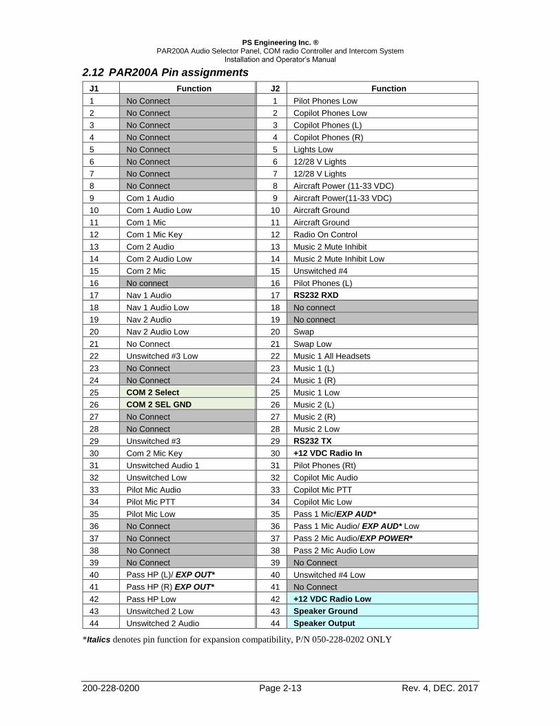
EXPANSION. .................................................................................................................................. 2-8 2.7.2 MUSIC INPUTS................................................................................................................... 2-9 2.7.3 MUSIC MUTING ................................................................................................................. 2-9 2.8 ADJUSTMENTS ................................................................................................................................... 2-9 2.9 MICROPHONE GAIN REDUCTION ..................................................................................................... 2-10 2.10 COMMUNICATIONS ANTENNA INSTALLATION NOTES ................................................................. 2-11 2.10.1 ANTENNA LOCATION .................................................................................................... 2-11 2.11 TY91/92(L) ADJUSTMENTS ........................................................................................................... 2-11 2.11.1 RADIO SIDETONE & RADIO SQUELCH ADJUSTMENT ................................................... 2-11 2.11.2 RADIO FREQUENCY SPACING, 25 KHZ OR 8.33 KHZ ..................................................... 2-11 2.12 PAR200A PIN ASSIGNMENTS ........................................................................................................ 2-13 2.13 POST INSTALLATION CHECKOUT ................................................................................................. 2-14

PS Engineering Inc. ® PAR200A Audio Selector Panel, COM radio Controller and Intercom System

Installation and Operator’s Manual

200-228-0200 Page ii Rev. 4, DEC. 2017

2.14 UNIT INSTALLATION...................................................................................................................... 2-14 2.15 OPERATIONAL CHECKOUT ........................................................................................................... 2-14 2.15.1 TY91/92 CHECKOUT..................................................................................................... 2-14 2.15.2 TELEPHONE CHECKOUT ............................................................................................ 2-15 2.16 FINAL INSPECTION ........................................................................................................................ 2-15 Section III OPERATION ............................................. 3-1 3.1 SCOPE .............................................................................................................................................. 3-1 3.2 POWER AND FAIL SAFE (1) ................................................................................................................ 3-1 3.2.1 TY91/92(L) RADIO POWER (AS COM 1 ONLY) ................................................................ 3-1 3.2.2 ICS AND RADIO VOLUME CONTROLS (1) ......................................................................... 3-1 3.3 COMMUNICATIONS TRANSMIT (XMT) SELECTION (2).................................................................... 3-2 3.4 COM AUDIO SELECTOR (3) .............................................................................................................. 3-2 3.5 NAVAID AUDIO SELECTION (4).......................................................................................................... 3-2 3.6 COCKPIT SPEAKER (10) .................................................................................................................... 3-2 3.7 VHF TRANSCEIVER CONTROL (5) .................................................................................................... 3-3 3.7.1 FREQUENCY SELECTION (6) .............................................................................................. 3-3 3.7.2 RADIO SQUELCH ............................................................................................................... 3-4 3.7.3 MONITOR MODE (WHEN PAR200A IS COM 1 OR STAND ALONE ONLY) ......................... 3-4 3.7.4 TUNING 8.33 KHZ CHANNEL SPACING .............................................................................. 3-5 3.8 INTERCOM OPERATION (8) ............................................................................................................... 3-6 3.8.1 INTELLIVOX® VOX-SQUELCH .......................................................................................... 3-6 3.8.2 MONO HEADSETS IN STEREO INSTALLATION ................................................................... 3-6 3.8.3 INTERCOM MODES (8) ...................................................................................................... 3-7 3.9 BLUETOOTH OPERATION ................................................................................................................... 3-7 3.9.1 BLUETOOTH TELEPHONE CONNECTION ........................................................................... 3-7 3.9.2 TELEPHONE (TEL) OPERATION ........................................................................................ 3-7 3.10 MUSIC INPUTS ................................................................................................................................. 3-8 3.10.1 MUSIC MUTING (9) ......................................................................................................... 3-8 Section IV – Warranty and Service ..................................... 4-1 4.1 WARRANTY ........................................................................................................................................ 4-1 4.2 FACTORY SERVICE ............................................................................................................................ 4-1 Appendix A – External PTT Hook Up .................................................................... A

Appendix B – PAR200A Installation Drawings ............................................................. B 6.1 TY91/92 RADIO INSTALLATION DRAWINGS ....................................................................................... B Appendix C – J1 Connector Interconnect ..................................................................... C

Appendix D – J2 Connector Interconnect .................................................................... D 8.1 EXPANSION UNIT INTERCONNECT (050-228-0202 ONLY) ................................................................. D Appendix E – Instructions for FAA Form 337 and continuing airworthiness ................ E 9.1 INSTRUCTIONS FOR FAA FORM 337, AUDIO PANELS ......................................................................... E 9.2 INSTRUCTIONS FOR CONTINUING AIRWORTHINESS, AUDIO SYSTEM ................................................ E 9.3 ICA FOR TRIG TY91/92 RADIO: .......................................................................................................... E Appendix F – RTCA DO160G Environmental Qualification Form ............................... F

Rev Date Change

0 June 2014 Release of PAR200A version

1 July 2015 EASA Approval Incorporated

2 September 2015 Corrected wiring diagram Fig 7-1.

3 June 2017 Extend applicability to include Trig TY92L

4 December 2017 Add passenger intercom expansion capability, 050-228-0202 ONLY

PS Engineering Inc. ® PAR200A Audio Selector Panel, COM radio Controller and Intercom System

Installation and Operator’s Manual

200-228-0200 Page 1-1 Rev. 4, DEC. 2017

Section I – GENERAL INFORMATION

1.1 INTRODUCTION

The PAR200A represents another evolutionary step in cockpit audio control and intercommunications utility.

Using our patented IntelliVox® design and pilot programmable configurations, this marks the next level of

audio control. The unit is designed for outstanding ergonomics and visually defined mode annunciation and

selection.

Before installing and/or using this product, please read this manual completely. This will ensure that you will

take full advantage of all the advanced features in the PAR200A.
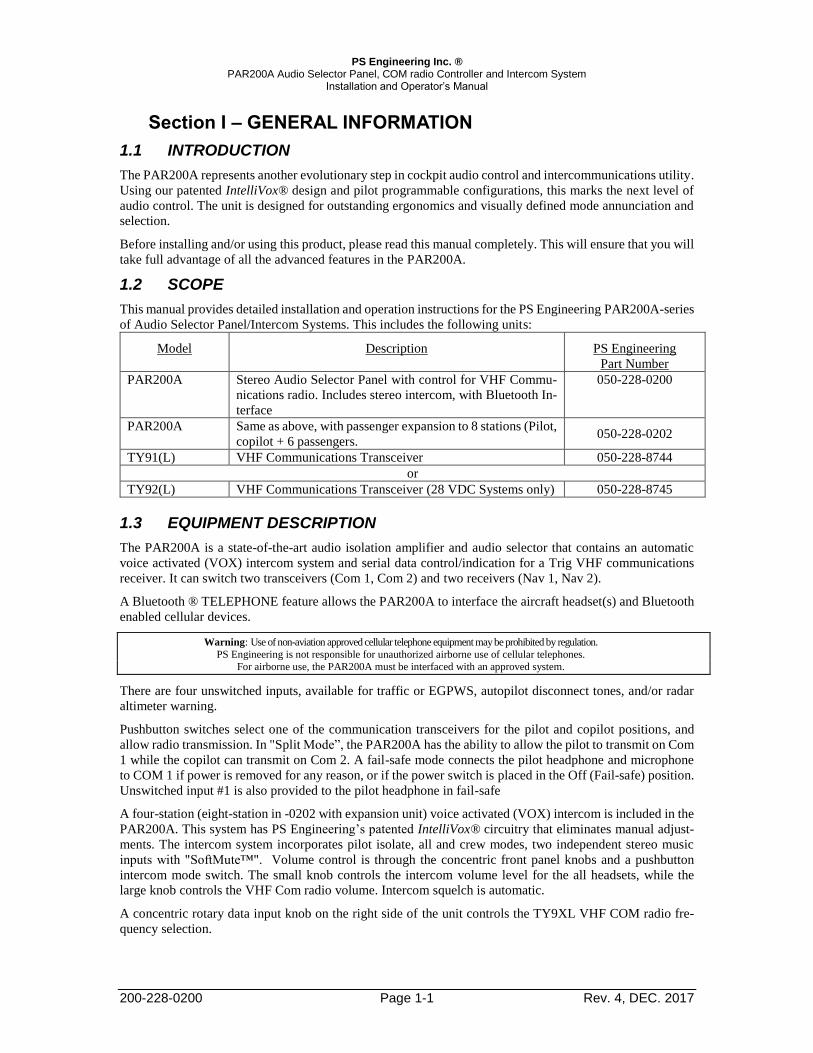
1.2 SCOPE

This manual provides detailed installation and operation instructions for the PS Engineering PAR200A-series

of Audio Selector Panel/Intercom Systems. This includes the following units:

Model Description PS Engineering

Part Number

PAR200A Stereo Audio Selector Panel with control for VHF Commu-

nications radio. Includes stereo intercom, with Bluetooth In-

terface

050-228-0200

PAR200A Same as above, with passenger expansion to 8 stations (Pilot,

copilot + 6 passengers. 050-228-0202

TY91(L) VHF Communications Transceiver 050-228-8744

or

TY92(L) VHF Communications Transceiver (28 VDC Systems only) 050-228-8745

1.3 EQUIPMENT DESCRIPTION

The PAR200A is a state-of-the-art audio isolation amplifier and audio selector that contains an automatic

voice activated (VOX) intercom system and serial data control/indication for a Trig VHF communications

receiver. It can switch two transceivers (Com 1, Com 2) and two receivers (Nav 1, Nav 2).

A Bluetooth ® TELEPHONE feature allows the PAR200A to interface the aircraft headset(s) and Bluetooth

enabled cellular devices.

Warning: Use of non-aviation approved cellular telephone equipment may be prohibited by regulation.

PS Engineering is not responsible for unauthorized airborne use of cellular telephones.

For airborne use, the PAR200A must be interfaced with an approved system.

There are four unswitched inputs, available for traffic or EGPWS, autopilot disconnect tones, and/or radar

altimeter warning.

Pushbutton switches select one of the communication transceivers for the pilot and copilot positions, and

allow radio transmission. In "Split Mode”, the PAR200A has the ability to allow the pilot to transmit on Com

1 while the copilot can transmit on Com 2. A fail-safe mode connects the pilot headphone and microphone

to COM 1 if power is removed for any reason, or if the power switch is placed in the Off (Fail-safe) position.

Unswitched input #1 is also provided to the pilot headphone in fail-safe

A four-station (eight-station in -0202 with expansion unit) voice activated (VOX) intercom is included in the

PAR200A. This system has PS Engineering’s patented IntelliVox® circuitry that eliminates manual adjust-

ments. The intercom system incorporates pilot isolate, all and crew modes, two independent stereo music

inputs with "SoftMute™". Volume control is through the concentric front panel knobs and a pushbutton

intercom mode switch. The small knob controls the intercom volume level for the all headsets, while the

large knob controls the VHF Com radio volume. Intercom squelch is automatic.

A concentric rotary data input knob on the right side of the unit controls the TY9XL VHF COM radio fre-

quency selection.

PS Engineering Inc. ® PAR200A Audio Selector Panel, COM radio Controller and Intercom System

Installation and Operator’s Manual

200-228-0200 Page 1-2 Rev. 4, DEC. 2017

1.4 APPROVAL BASIS — FAA TSO, EASA ETSO

1.1.1 PAR200A

The PAR200A-series Audio Selector Panels have FAA authorization under TSO C139 (Aircraft Audio Sys-

tems and Equipment). The VHF Communication Transceiver portion of the PAR200A holds TSO authori-

zations under TSO C169a.

The PAR200A-series Audio Selector Panels hold EASA authorization under ETSO C139 (Aircraft Audio

Systems and Equipment). The VHF Communication Transceiver portion of the PAR200A is EASA author-

ized under ETSO-2C169a. EASA.IM.210.10053809.

The partial TSO applies to C169a because the PAR200A unit provides control and display only for the TY91-

series of VHF communications equipment.

The audio system complies with relevant portions of ED-14C/DO-160G (Environmental Conditions and Test

Procedures for Airborne Equipment), DO-254, (Design Assurance Guidance for Airborne Electronic Hard-

ware) and ED-18/DO-214 (Audio Systems Characteristics and Minimum Operational Performance Stand-

ards for Aircraft Audio Systems).

NOTE: The conditions and tests for TSO approval of this article are minimum performance standards.

Those installing this article, on or in a specific type or class of aircraft, must determine that the

aircraft installation conditions are within the TSO standards. The article may be installed only

following 14 CFR Part 43 or the applicable airworthiness requirements.

1.1.2 Trig TY91/92-Series: The VHF Communication Radio (Trig Avionics TY91L/TY92L) is EASA and FAA-approved under

ETSO 210.10042695, Rev, B or Subsequent Revision, under 2C169a Class C, E, H1, H2, 4, 6, ETSO

2C128, TSO C169a Class C, E, 4, 6, TSO C128a TSO-C169a, ETSO 2C169a Class C, E, H1, H2, 4, 6,

ETSO 2C128, TSO C169a Class C, E, 4, 6, TSO C128a EUROCAE ED-23C, EUROCAE ED-67,

EUROCAE ED-14F (RTCA DO-160F), RTCA DO-186B, RTCA DO-207 ED-12B (RTCA DO-178B)

Level B DO-254 Level C

FCC Identification TY91 VZI00882 , TY92 VZI00879

Applicable documents EUROCAE ED-23C, EUROCAE ED-67, EUROCAE ED-14F (RTCA DO-160F),

RTCA DO-186B, RTCA Software ED-12B (RTCA DO-178B) Level B Hardware DO-254 Level C

Operation is subject to the following conditions:

This device may not cause harmful interference. This device must accept any interference received, including

interference that may cause undesired operation.

1.5 SPECIFICATIONS

Audio Selector/Intercom FAA TSO C139 EASA ETSO C139

Communications Transceiver FAA TSO-C169a (PARTIAL) EASA ETSO 2C169A

Environmental Qualification DO-160G A1C1BAESRXXXXXXZ B(XX)ABATTBXXA2E2 XXX

Operating Temperature Range: -20º C to 55ºC , short term -40°C to +70°C

Altitude: Up to 35,000 feet in an non-pressurized area

WEIGHT

PAR200A Unit

Rack with connectors

1.1 lb. (0..49 kg)

0.51 lb. (0.24 kg)

Dimensions Height: 1.3 in. (3.3 cm) Width: 6.25 in. (16.9 cm)

Depth behind panel 7.15 in. (18.16 cm)

AUDIO PANEL POWER REQUIREMENTS (Including Internal Lighting):

Voltage: 11-33 VDC (18-33 with TY92)

Maximum Current: 2.5 Amp (Externally protected by a 3A pull-type

breaker)

PS Engineering Inc. ® PAR200A Audio Selector Panel, COM radio Controller and Intercom System

Installation and Operator’s Manual

200-228-0200 Page 1-3 Rev. 4, DEC. 2017

Audio Selector Specifications

Audio selector panel input impedance: 510

Input Isolation: -60 dB (min.)

Receiver Inputs: 4 (Com 1, Com 2, Nav 1, Nav 2)

Unswitched Inputs: 4

Transmitter Selections: 3 (Com 1, Com 2,

Com1/2)

Headphone Impedance: 150 – 1000

Headphone Output: 38 mW each headset, no clipping <1% THD typical into 150

Speaker Output (into 4 ) with no clipping

14 VDC:

28 VDC:

3 Watts (min.)

10 Watts (min.)

Microphone Impedance: 150 - 600

Intercom Specifications Intercom Positions: 4 places (with individual IntelliVox® circuits) (8 with

expansion, -0202 ONLY)

Music Inputs: 2, (Independent, Stereo)

Music Muting: >-30 dB "Soft Mute" when Com or intercom active.

Distortion: <1% THD @ 38 mW into 150

Mic Freq. Response, 3 dB: 300 Hz - 6000 Hz

Music Freq. Response, 3 dB: 10 Hz – 26 kHz

TY91L VHF Transceiver Specifications Radio Type Amplitude Modulation (AM) Aircraft Transceiver

Channels (Transmit & receive) 760 channels, 25KHz spacing

2280 channels, 8.33 kHz spacing

118.000 – 136.992MHz

Frequency Selection On PAR200A Audio Panel

Frequency Display Alpha/numeric LCD display (with backlighting) on

PAR200A

Frequency control PLL frequency synthesis, which is microprocessor

controlled Memory is store in non-volatile EPROM

Power consumption Receive (no signal)

Transmit

2.8W @ 14VDC

3.2A

Input Voltage 11-33 VDC 5A Circuit Breaker.

Power output 5 watts (nominal) VSWR Tolerance < 2:1 for best

operation (5:1 without damage)

Receiver sensitivity -6dB SINAD @ 5µV (1KHz audio with 70% modu-

lation)

Data Interface RS232

Headset volume output Nominal 100 milliwatts output to 600 Ω

Temperature range -20 to +70 degrees Celsius

Stability < +/- 4.00 ppm

Dimensions W-2.5” x H-1.9” x D6.3” (plus 1.5” for harness) W-

66mm xH-48mm x D-160 (plus 35mm for har-

ness)

Weight .77 lbs.

.350 kg

FCC ID: VZI00882

PS Engineering Inc. ® PAR200A Audio Selector Panel, COM radio Controller and Intercom System

Installation and Operator’s Manual

200-228-0200 Page 1-4 Rev. 4, DEC. 2017

TY92L VHF Transceiver Specifications Radio Type Amplitude Modulation (AM) Aircraft Transceiver

Channels (Transmit & receive) 760 channels, 25KHz spacing

2280 channels, 8.33 kHz spacing

118.000 – 136.992MHz

Frequency Selection On PAR200A Audio Panel

Frequency Display Alpha/numeric LCD display (with backlighting) on

PAR200A

Frequency control PLL frequency synthesis, which is microprocessor con-

trolled Memory is store in non-volatile EPROM

Power consumption Receive (no signal)

Transmit

2.8W @ 28VDC

80 W @ 28VDC, 3.2A

Input Voltage 18-33 VDC 5A Circuit Breaker. (28 V Systems only)

Power output 16 watts (nominal) VSWR Tolerance < 2:1 for best op-

eration (5:1 without damage)

Receiver sensitivity -6dB SINAD @ 5µV (1KHz audio with 70% modula-

tion)

Data Interface RS232

Headset volume output Nominal 100 milliwatts output to 600 Ω

Temperature range -20 to +70 degrees Celsius

Stability < +/- 4.00 ppm

Dimensions W-2.5” x H-1.9” x D6.3” (plus 1.5” for harness) W-

66mm xH-48mm x D-160 (plus 35mm for harness)

Weight .77 lbs. (.350 kg)

FCC ID: VZI00879

1.6 EQUIPMENT SUPPLIED

One ea. of the following items:

Model Description PS Part Number Trig P/N

PAR200A PAR200A Audio Panel with intercom and radio function control 050-228-0200

And ONE of the TY9X below

TY91(L) VHF Communications Transceiver (6 watts) 050-228-8744 00882-00-05

TY92(L) VHF Communications Transceiver (16 watts) 050-228-8745 01196-00-05

OR

PAR200A PAR200A Audio Panel with intercom and radio function control 050-228-0202

And ONE of the TY9X below

TY91(L) VHF Communications Transceiver (6 watts) 050-228-8744 00882-00-05

TY92(L) VHF Communications Transceiver (16 watts) 050-228-8745 01196-00-05

Installation Kit: 250-890-0000, contains:

Description Quantity Part Number

PAR200A installation rack assembly 1 430-890-0040

PAR200A Rack back plate 1 430-890-0050

44-pin connector kit 2 120-891-2045-

Backshell, connector 2 625-025-2465

Backshell Retainer 2 431-891-0100

4 40 X 7/16 screw w/nylon patch 4 475-440-0007

4 40 X 3/8 screw w/lock washer 4 475-440-1038

4 40 X 1/8 screw w/lock washer 2 475-440-0001

Solder Lug 2 475-009-0001

Cable Clamp 1 625-001-0002

#6-32 x ½” Flat head Philips screw 6 475-632-0012

#6-32 Clip Nut 6 475-630-0002

PS Engineering Inc. ® PAR200A Audio Selector Panel, COM radio Controller and Intercom System

Installation and Operator’s Manual

200-228-0200 Page 1-5 Rev. 4, DEC. 2017

TY91/92 Installation Kit 250-228-0200, Containing:

Description Quantity Part Number DB 25 Connector , Crimp type 1 425-025-0010

DB 25 Connector hood 1 625-025-0001

DB 25 Thumb Screws 4-40 x 1.94 2 475-002-0002

Crimp female sockets 25 425-020-5090

TNC Crimp Connector 1 425-400-1223

1.7 EQUIPMENT REQUIRED BUT NOT SUPPLIED a. Circuit Breaker: 1 ea; 3 amp PULL TYPE REQUIRED for PAR200A

b. Circuit Breaker: 1 ea; 5 amp PULL TYPE REQUIRED for transceiver power (to TY91/92)

c. Headphone Jacks (up to 4 Stereo, as Required)

d. Microphone Jacks (up to 4 as Required)

e. Headphones, 150 (Stereo), up to 4 as required

f. Microphones, up to 4 as required

g. VHF Communication antenna 118-137 MHz, VSWR <2:1 (FAA-TSO approved is recommended)

h. Mounting hardware for TY91, as appropriate

i. Interconnect Wiring, coaxial cable (RG400 or RG142B or equivalent)

1.8 LICENSE REQUIREMENTS

In some localities other than the United States, an Aircraft Radio Station license may be required. In the

United States, you do not need a license to operate a two-way VHF radio aboard aircraft operating domesti-

cally. Aircraft operating domestically do not land in a foreign country or communicate via radio with foreign

ground stations. Flying in international or foreign airspace is permitted, so long as the previous conditions

are met. If you travel to a foreign destination, however, (e.g., Canada, Mexico, Bahamas, British Virgin

Islands) a license is required. Visit http://wireless.fcc.gov for more information.

PS Engineering Inc. ® PAR200A Audio Selector Panel, COM radio Controller and Intercom System

Installation and Operator’s Manual

200-228-0200 Page 2-1 Rev. 4, DEC. 2017

Section II - INSTALLATION

2.1 GENERAL INFORMATION

2.1.1 SCOPE

This section provides detailed installation and interconnection instructions for the PS Engineering PAR200A

Audio Selector Panel/Intercom/ with VHF communication radio controls.

Please read this manual carefully before beginning any installation to prevent damage and post-installation

problems. Installation of this equipment requires special tools and knowledge.

2.1.2 Certification Requirements

NOTE

The PAR200A Intercom is FAA approved under TSO C139/ETSO C139 (Aircraft Audio Systems and Equip-

ment) and contains partial elements of TSO C169a/ETSO 2C169A (VHF Radio Communications Transceiver

Equipment Operating Within Radio Frequency Range 117.975 To 137.000 Megahertz).

The partial TSO applies to C169a, because the PAR200A unit provides control and display only for the

TY91-series of VHF communications equipment.

The conditions and tests for TSO approval of this article are minimum performance standards. Those

installing this article, on or in a specific type or class of aircraft, must determine that the aircraft instal-

lation conditions are within the TSO standards.

The article may be installed only following 14 CFR Part 43 or the applicable airworthiness require-

ments.

See FAA AC 20-41A for information regarding substitute TSO Aircraft Equipment.

2.2 Unpacking and Preliminary Inspection

Use care when unpacking the equipment. Inspect the units and parts supplied for visible signs of shipping

damage. Examine the unit for loose or broken buttons, bent knobs, etc. Verify the correct quantity of com-

ponents supplied with the list in Section 1.6 (B). If any claim is to be made, save the shipping material and

contact the freight carrier. Do NOT return units damaged in shipping to PS Engineering. If the unit or acces-

sories show any sign of external shipping damage, contact PS Engineering to arrange for a replacement.

Under no circumstances attempt to install a damaged unit in an aircraft. Equipment returned to PS Engineer-

ing for any other reason should be shipped in the original PS Engineering packaging, or other UPS approved

packaging.

2.3 Equipment Installation Procedures

2.3.1 Cooling Requirements

Forced air-cooling of the PAR200A is not required. However, the units should be kept away from heat pro-

ducing sources (i.e. defrost or heater ducts, dropping resistors, heat producing avionics) without adequate

cooling air provided.

2.3.2 Mounting Requirements

The PAR200A must be rigidly mounted to the instrument panel of the aircraft structure, within view and

reach of the pilot position(s). The unit may be mounted in any area where adequate clearance for the unit and

associated wiring bundle exist.

To prevent noise, avoid installing the unit close to high current devices or systems with high-voltage pulse

type outputs, such as DME or transponders. Avoid running the interconnecting bundles near any high current

wires.

PS Engineering Inc. ® PAR200A Audio Selector Panel, COM radio Controller and Intercom System

Installation and Operator’s Manual

200-228-0200 Page 2-2 Rev. 4, DEC. 2017

2.3.3 Trig TY91/TY92 mounting requirements

The TY91/92 remote VHF Communications radio is mounted to the aircraft structure with 4 ea #6-32 (not

supplied) screws through the mounting flange. Guidance can be found in AC 43.13-2B, Chapter 2.

Figure 2-1 TY91/92 VHF Transceiver (Remote Mount)

2.3.4 Audio Panel Mounting Rack Installation

Remove the audio panel from the mounting tray by unscrewing the 3/32" hex-head screw that is in the center

of the unit. Use caution to avoid hitting the photo-detector lens. Carefully slide the unit free of the tray. Set

the unit aside in a safe location until needed. Install the tray using six clip nuts (475-630-0002), and six FHP

6-32 x ½" screws (475-632-0012). The audio selector panel must be supported at front and rear of the mount-

ing tray.

2.4 Cable Harness Wiring

Referring to the appropriate Appendix, assemble a wiring harness as required for the installation. All wires

must be MIL-SPEC in accordance with current regulations. Two- and three-conductor shielded wire must be

used where indicated, and be MIL-C-27500 or equivalent specification. Proper stripping, shielding and sol-

dering technique must be used at all times. It is imperative that correct wire be used.

Refer to FAA Advisory Circular 43.13-2B for more information. Failure to use correct techniques may result

in improper operation, electrical noise or unit failure. Damage caused by improper installation will void the

PS Engineering warranty.

Custom factory wiring harnesses can be purchased from PS Engineering, call 865-988-9800 for details or

visit our website http://www.ps-engineering.com/downloads.shtml and click on Work Sheet for the appro-

priate product.

2.4.1 Noise

Due to the variety and the high power of radio equipment often found in today's general aviation aircraft,

there is a potential for both radiated and conducted noise interference.

The PAR200A power supply is specifically designed to reduce conducted electrical noise on the aircraft

power bus by at least 50dB. Although this is a large amount of attenuation, it may not eliminate all noise,

particularly if the amplitude of noise is very high. There must be at least 13.8 VDC present at the connector,

J2 pins 8 & 9, of the PAR200A for the power supply to work in its designed regulation. Otherwise, it cannot

adequately attenuate power line noise. Shielding can reduce or prevent radiated noise (i.e., beacon, electric

gyros, switching power supplies, etc.) However, installation combinations can occur where interference is

possible. The PAR200A was designed in a RFI hardened chassis and has internal Electromagnetic Interfer-

ence (EMI) filters on all inputs and outputs.

Ground loop noise occurs when there are two or more ground paths for the same signal (i.e., airframe and

ground return wire). Large cyclic loads such as strobes, inverters, etc., can inject noise signals onto the air-

PS Engineering Inc. ® PAR200A Audio Selector Panel, COM radio Controller and Intercom System

Installation and Operator’s Manual

200-228-0200 Page 2-3 Rev. 4, DEC. 2017

frame that are detected by the audio system. Follow the wiring diagram very carefully to help ensure a min-

imum of ground loop potential. Use only Mil Spec shielded wires (MIL-C-275000, or better). Under no

circumstances, combine a microphone and headphone wiring into the same shielded bundle. Always use a 2-

or 3-conductor, shield wire as shown on the installation-wiring diagram.

The shields can be daisy-chained together, and then connected to the ground lugs mounted on the center of

the back plate.

Radiated signals can be a factor when low-level microphone signals are "bundled" with current carrying

power wires. Keep these cables physically separated. It is very important that you use insulated washers to

isolate the ground return path from the airframe to all headphone and microphone jacks.

2.4.1.1 Music Inputs and Noise

PAR200A units utilize differential music inputs to help prevent noise from entering the music system. This

feature is usually transparent to the installer; however, it is important that the appropriate music signal and

ground connections are made directly to the dedicated music signal and ground inputs on the PAR200A. The

power for IFE and audio panel should be a common bus.

If a music jack is installed for Music 1 or 2, we strongly recommend isolating the jack from airframe ground,

by using an insulated mounting plate.

NOTE Adding a high-performance audio control system, particularly in conjunction with high-performance active

noise canceling headsets, cannot improve on older avionics that were designed for cabin-speaker use. PS

Engineering makes no claim that the audio panel will provide a noise-free audio quality under all installation

conditions, particularly with older avionics.

2.4.2 Audio Panel Tray and Connector Assembly

The rack connectors mate with two 44-pin connectors in the PAR200A. The connectors are a sub-miniature

crimp-type, and require the use a hand crimp tool, from table below (or equiv.). The connectors are mounted

to the tray back plate with #4-40 screws (475-440-1038), from the inside of the tray and the mounting block,

431-891-0100. Ensure that proper strain relief and chafing precautions are made during wiring and installa-

tion, using the cable clamp (625-001-0002).

Manufacturer Crimping Tool Positioner Extraction tool

AMP 601966-1 601966-6 91067-1

Daniels AFM8 K42 M24308-1

ITT-Cannon 995-0001-584 995-0001-739 91067-1

Table 2-1 PAR200A Connector Pin crimping tools

Manufacturer Crimping Tool Positioner Extraction tool

Mil-Spec M22520/2-01 M22520/2-08

Daniels AFM8 K13-2

Table 2-2 TY91/92 Connector Crimping tools

2.4.3 Audio Panel interface

The PAR200A is designed to interface with standard aircraft avionics, and presents a 500 receiver imped-

ance. For best results, a twisted-shielded cable is recommended from the avionics audio source to the audio

panel, with the shield grounded at the audio panel end.

Inputs N1 and N2 can be used to control navigation receiver audio, J1 Pins 17 WRT 18 and J1 19 WRT 20,

respectively.

Some avionics do not provide a separate audio low, and may introduce additional electrical noise into the

system. For best results, connect the audio low from the audio panel to the radio ground, using one conductor

of the twisted-shielded cable.

PS Engineering Inc. ® PAR200A Audio Selector Panel, COM radio Controller and Intercom System

Installation and Operator’s Manual

200-228-0200 Page 2-4 Rev. 4, DEC. 2017

2.5 TY91/92 VHF COM Interface

2.5.1 TY91 Connector (Trig TY91 (L) TY92 (L) -05 only)

The TY91/92 has a 25-pin crimp type connector.

1 Com Audio Low

2 COM Audio High

3 No Connect

4 No Connect

5 RS232RX (data in-TX)

6 RS232TX (data out-RX)

7 No Connect

8 No Connect

9 Aircraft Ground

10 No Connect

11 No Connect

12 Controller Radio Power

13 Radio On

14 No Connect

15 COM Mic Key

16 No Connect

17 No Connect

18 Transmit Interlock

19 Airframe Ground

20 No Connect

21 No Connect

22 Ground (Not Used)

23 COM Mic Audio Hi

24 Aircraft Power

25 Aircraft Power

2.5.2 Interfacing the TY91/92(L) as Single, COM 1 or COM 2

The PAR200A/ Trig TY91/92(L) can be configured to be a stand-alone COM, or as COM 1 or COM 2 in a

multiple radio installation. In this case, PS Engineering recommends that the PAR200A/TY91/92(L) be used

as COM 2. In the event of a failure, the PAR200A will be in fail-safe, and COM 1 can be used.

The PAR200A must be configured with an installation strap when PAR200A radio is being used as COM 2,

by applying ground to J1, Pin 25. J1, pin 26 is a convenient ground.

NOTE: When wiring remote radio as COM 1, leave J1-25 open. When wiring as COM 2, connect J1-25

to J1-26.

If the TY91/92(L) is used as COM 1, the PAR200A can fail-safe to it, because it is divided internally as audio

panel and COM control. In addition, the TY91/92(L) power supply is provided by an independent circuit

breaker and power supply in the PAR200A. See §3.2.1 for operational information.

When properly selected, the PAR200A LCD display will read either COM 1 (includes stand-alone), or COM

2.

2.5.3 Antenna Cable

Use a high quality 50-ohm coaxial cable, such as RG400 or RG142B. When routing the cable, ensure that

you:

Route the cable away from sources of heat.

Route the cable away from potential interference sources such as ignition wiring, 400Hz genera-

tors, fluorescent lighting and electric motors.

Allow a minimum separation of 300mm (12 inches) from an ADF antenna cable. Keep the cable run as short as possible.

PS Engineering Inc. ® PAR200A Audio Selector Panel, COM radio Controller and Intercom System

Installation and Operator’s Manual

200-228-0200 Page 2-5 Rev. 4, DEC. 2017

Avoid routing the cable round tight bends.

Avoid kinking the cable even temporarily during installation.

Secure the cable so that it cannot interfere with other systems.

2.5.4 TY91/92 TNC Antenna connection

The VHF Com radio uses a solder/crimp TNC connector, Amphenol 31-2.

This section describes the technique for attaching the antenna cable to the supplied TNC connector.

The supplied connector can be completed using a wide range of commercial crimp tools (for example the

Tyco 5-1814800-3). The die apertures for the inner pin and the outer shield should be approximately 1.72

mm and 5.41 mm respectively.

1. Strip back the coax cable to the dimensions in the table, as shown in the diagram below. Slide 25

mm (1 inch) of heat shrink tubing over the cable.

2. Slide the outer crimp sleeve over the cable – it must go on before securing the center contact.

3. Crimp the center contact to the cable.

4. Insert the cable into the connector – the center contact should click into place in the body, the in-

ner shield should be inside the body of the connector and the outer shield should be outside the

body.

5. Crimp the outer sleeve over the shield.

6. Slide heat shrink tubing forward (flush to connector) and heat to shrink the tubing.

2.5.5 VHF Communications Antenna Installation The antenna should be installed according to the manufacturer’s instructions. The following considerations

should be taken into account when locating the Antenna.

The antenna should be well removed from any projections, the engine(s) and propeller(s). It

should also be well removed from landing gear doors, access doors or others openings that will

break the ground plane for the antenna.

Avoid mounting the antenna within 2 feet of a GPS antenna, and as far as practical from any ELT

antenna.

PS Engineering Inc. ® PAR200A Audio Selector Panel, COM radio Controller and Intercom System

Installation and Operator’s Manual

200-228-0200 Page 2-6 Rev. 4, DEC. 2017

If the simultaneous use of two radio units is required, then each antenna should be as far apart as

practicable for maximum isolation. We would recommend placing one antenna on top and one on

the bottom of the airframe. The Transmit Interlock function should also be used in this case (sec-

tion 5.6.8). Where practical, plan the antenna location to keep the cable lengths as short as possible and avoid

sharp bends in the cable to minimize the VSWR.

Electrical connection to the antenna should be protected to avoid loss of efficiency because of the presence

of liquids or moisture. All antenna feeders shall be installed in such a way that a minimum of RF energy is

radiated inside the aircraft.

2.5.5.1 Antenna Ground Plane

When a conventional aircraft monopole antenna is used, it relies on a ground plane for correct behavior. For

ideal performance, the ground plane should be as large as practical; in any case at least one square meter. In

a metal skinned aircraft this is usually easy to accomplish, but is more difficult in a composite or fabric

skinned aircraft. In these cases, a metallic ground plane should be fabricated and mounted under the antenna.

The thickness of the material used to construct the ground plane is not critical, providing it is sufficiently

conductive. A variety of proprietary mesh and grid solutions are available. Refer to Advisory Circular

AC43.13-2B, Chapter 3.

2.6 TELEPHONE (Duplex) Function for Bluetooth ® capable Cell Phones

The TELEPHONE mode in the PAR200A is also compatible with cellular telephones with Bluetooth®.

Hands-free headset interface. There is no wiring required, all functions are handled in the Bluetooth tele-

phone.

The PAR200A Bluetooth® interface is always “discoverable”, so you just need to search for the PAR200A

from your Bluetooth-equipped phone or music source. The default access code is 0000, if needed. Once the

PAR200A has been “paired” with your Bluetooth device.

The telephone is distribution as dictated by the ISO, ALL, CREW mode.

ISO mode - only the Pilot is on the telephone.

CREW mode - only the Pilot and Copilot are on the telephone.

ALL mode - everyone is on the telephone.

You can answer a call when you hear the “telephone ringing” in your headset. To answer the phone call will

require you to have access to your phone and selecting the answer function of that telephone. It is not possible

to answer the phone from the audio panel.

2.6.1 Pairing separate music and telephone devices

It is possible to use a different music source (iPad, iPod with Bluetooth adapter, Bluetooth enabled laptop,

etc.) and telephone. However, the telephone source must be paired first, before the music, if the telephone

also has music streaming capability. Otherwise, the music source will take over the telephone port.

Only one can be a phone. If the telephone can provide both telephone and streaming music, when the phone

is connected, it will automatically disconnect the music device. If it is possible to turn off the music streaming

function on the telephone, then both the telephone and a separate Bluetooth® enabled music device can be

use at the same time.

If Bluetooth connections become unreliable or do not connect, you may need to reset the PAR200A. Turn

the PAR200A off, press & hold the N1 & N2 buttons while turning the unit back on, continue to hold the N1

& N2 for 3 seconds.

PS Engineering Inc. ® PAR200A Audio Selector Panel, COM radio Controller and Intercom System

Installation and Operator’s Manual

200-228-0200 Page 2-7 Rev. 4, DEC. 2017

NOTE

FCC Regulations (47 CFR 22.925) prohibit airborne operation of cellular phones;

Cellular telephones installed in or carried aboard airplanes, balloons or any other type of aircraft must not

be operated while such aircraft are airborne (not touching the ground). When any aircraft leaves the ground,

all cellular telephones on board that aircraft must be turned off. The use of cellular telephones while aircraft

is on the ground is subject to FAA regulations.

FAA Regulation 14 CFR 91.21(5) allows for use of portable electronic devices that the operator of the air-

craft has determined will not cause interference with the navigation or communication system of the air-

craft on which it is to be used.

PS Engineering, Inc. does not endorse using unapproved cellular telephone equipment in flight, and takes

no responsibility for the user’s action. PS Engineering does not guarantee compatibility with personal cellu-

lar telephones. For a list of phones that have been tested, visit www.ps-engineering.com.

2.6.2 Telephone sidetone

The PAR200A is shipped from the factory with Telephone sidetone enabled. The PAR200A will provide cell

phone sidetone (your side of the telephone conversation) in the factory configuration. Some telephones al-

ready provide sidetone, and the PAR200A can be configured to disable internal sidetone by placing the DIP

switch in the proper configuration. Authorized PS Engineering installers should contact the factory for in-

structions.

J5 Switch 6 Cell phone sidetone created by audio panel OFF

No cell phone sidetone ON

Table 2-3 Telephone sidetone switch

2.6.3 "Swap" Mode

When a momentary, normally open, push-button switch is connected between pin 20 on the J2 connector and

aircraft ground, the user can switch between Com 1 and 2 by depressing this switch without having to turn

the mic selector switch. This yoke-mounted switch eliminates the need to remove your hands from the yoke

to change transceivers.

2.6.4 Backlighting

The PAR200A has an automatic dimming of the pushbutton annunciation LEDs controlled by a photocell.

Control of the unit backlighting is through the aircraft avionics dimmer. For 12-Volt aircraft, connect J2 Pins

6 and 7 to the aircraft dimmer bus, and pin 5 to ground.

The LCD display backlighting is controlled by the automatic photocell dimming. In addition, the text inverts

for nighttime mode when the ambient light is low.

If an external dimmer control is not used, a constant maximum back light illumination can be established for

viewing. Pin 6 or 7 (depending on system voltage) must be tied to power (J2, pin 8 or 9) for the back lighting

system to work. The photocell mounted in the unit face will automatically adjust the intensity of the push-

button annunciation green LEDs.

2.6.5 Unswitched inputs

J1, pins 31, 29 and J2 pin 15 are unswitched, unmuted (by transmitter keying), inputs # 1, 3 and 4, respec-

tively. These inputs are presented to the pilot and copilot regardless of the audio configuration, and will mute

the entertainment inputs based on the mode. These 510 Ω inputs can be used for altimeter DH audio, GPS

waypoint audio, autopilot disconnect tones, or any other critical audio signal. Unswitched #1 is always pre-

sented to the crew headphones, and is available to the pilot in fail-safe (off) mode.

PS Engineering Inc. ® PAR200A Audio Selector Panel, COM radio Controller and Intercom System

Installation and Operator’s Manual

200-228-0200 Page 2-8 Rev. 4, DEC. 2017

Unswitched

Input

Hear in

Fail Safe

Hear in

Crew Headset

Gain

1 Yes Yes 1:1(fixed)

2 No Yes 1:1(fixed)

3 No Yes Adjustable

4 No Yes 1:1(fixed)

Table 2-4 Unswitched input table

J1, pins 31, 29 and J2 pin 15 are unswitched, unmuted inputs # 1, 3 and 4, respectively. These inputs are

presented to the pilot and copilot regardless of the audio configuration, and will always mute the entertain-

ment inputs. These 510Ω inputs can be used for altimeter DH audio, GPS waypoint audio, autopilot discon-

nect tones, or any other critical audio signal.

The audio low for unswitched #4 (J2, pin 15) should be connected to a convenient audio low. However, this

should NOT be connected to Music Low.

Unswitched #1 is presented to the pilot headphone in fail-safe (off) mode.

NOTE

Inputs 1, 2 and 4 are fixed (1:1), and any audio level adjustments must be made at the input source. Unswitched #3 has a

variable adjustment control located on the bottom side of the unit. This control allows you to control the volume level of

that unswitched input from 50% to 200% of the input level. Refer to Adjustments section.

2.7 Intercom wiring

See Appendix C and D for intercom connection configurations. It is critical to the proper operation of this

system to have this connector wiring made in accordance with these diagrams. Use 2- and 3-conductor, MIL-

spec cable as shown. Connect the shields at the audio panel end only, and tie to the audio low inputs as shown.

NOTE The system harness can be custom made by PS Engineering, Inc. Simply call the factory or www.ps-engi-

neering.com to obtain a wire harness work sheet. The harness will be made to your specifications and fully

functionally tested. Harness can be ordered with jack, or without the intercom jacks installed, for easier wire

routing through the aircraft.

2.7.1 PAR200A with Expansion Unit (050-228-0202) with P/N 11636 IntelliPAX Expansion

The PAR200A can be configured with as an 8-station intercom with a remote mounted IntelliPAX Intercom

Expansion unit (P/N 11636R), and PAR200A Part Number 050-228-0202. In this configuration, pilot and

copilot are connected to the audio panel, but all passengers’ stations are connected to the IntelliPAX Expan-

sion unit. See wiring diagram in §8.1. Music comes from the sources in the PAR200A and all intercom

volume is controlled by the PAR200A inner volume control.

11636R EXP UNIT Connector

Function PAR200A J2 PAR200A J1

3 Expansion Audio to Audio Panel 35

14 Audio Low 36

1 Expansion Power 37

15 Expansion Audio from Audio

Panel (Left)

40

2 Expansion Audio from Audio

Panel (Right) 41

Table 2-5 Expansion Interconnections, 050-228-0202 ONLY

PS Engineering Inc. ® PAR200A Audio Selector Panel, COM radio Controller and Intercom System

Installation and Operator’s Manual

200-228-0200 Page 2-9 Rev. 4, DEC. 2017

2.7.2 Music Inputs

The PAR200A has two INDEPENDENT inputs wired into the rear connectors, in addition to the Bluetooth®

music streaming (which is presented as Music 1). Music input number 1 is J2 pins 23 (left channel) and 24

(right channel), with respect to pin 25, and Music number 2 is connected to 26 (left channel), 27 (right chan-

nel), with respect to 28.

Music #1 is available to the pilot and copilot positions, only, in normal configuration. Music 1 can be heard

by all aircraft occupants, if Music 1 all headsets is activated with a switch connected to the PAR200A. See

§2.7.2.1

Music 2 is only heard by the passengers.

See §3.10 for music distribution information.

NOTE Use the lo w-level output of any addit iona l enter tainment device to connect to the au-

dio panel . Maximum signal leve l i s 3 VAC p -p. DO NOT use a speaker - leve l output ,

th is wi l l cause internal damage in the aud io panel .

2.7.2.1 Music 1 all headsets (J2, Pin 22)

If J2, Pin 22 is connected to aircraft ground, Music 1 will also be heard in the passengers’ headsets. Music 2

will be disabled when J2, Pin 22 is grounded.

2.7.3 Music muting

The PAR200A incorporates a "Soft Mute™" system. This will mute the music devices during intercom con-

versation or radio reception. The four muting modes are controlled by the front panel “Mute” button. See

§3.9 for more information.

CAUTION Local oscillators and internal signals from entertainment equipment can cause undesired interference with

other aircraft systems. Before takeoff, operate the entertainment devices to determine if there is any adverse

effect within the aircraft systems. If any unusual operation is noted in flight, immediately switch off the

entertainment devices.

All entertainment devices must be switched off for both takeoff and landing.

2.7.3.1 Music 2 Mute (J2 Pin 13 & 14)

Connecting J2 pin 13 to pin 14 (or ground) through a SPST switch places the music #2 music source into the

Karaoke Mode. In this mode, incoming music and intercom conversation will not mute the music for the

passengers’ intercom net. This allows uninterrupted music during casual conversation.

2.8 Adjustments

The PAR200A is factory adjusted to accommodate the typical requirements for most aircraft configurations.

There are three adjustments with access holes through the top cover (see §2.11) that allow the installer to

tailor the specific functions.

Unswitched Input 3 Volume, adjust from 50% to 200% of input value. Turn counterclockwise to

increase gain.

TEL VOL- The received telephone volume. The unit is set at the factory for 75% of volume. Turn

Clockwise to increase the TEL receive volume.

LCD CST: adjusts display contrast to suit individual preferences and ambient light.

DIP Switches (Mic gain and phone sidetone) – PS Engineering installers should call for the Service

Aid.

PS Engineering Inc. ® PAR200A Audio Selector Panel, COM radio Controller and Intercom System

Installation and Operator’s Manual

200-228-0200 Page 2-10 Rev. 4, DEC. 2017

SPRVOL

US3VOL

J1

TELVOL

LCDCST

Figure 2-2 – PAR200A Adjustments

2.9 Microphone gain reduction (only available for P/N 050-228-0200)

For installations in very noisy aircraft, a reduction in the intercom microphone input gain might be desirable.

The PAR200A has two DIP switches located on the main board that can switch the inputs to a lower gain

setting. PS Engineering installers call for the Service Aid.

Figure 2-3 DIP switches

Change the settings as shown in the table below.

Switch Bank Switch Noisy Cockpit Normal Cockpit

DIP Switches

(inside)

Unswitched 3

1 2 3 4 5 6

ON OFF ON OFF

LCD Contrast 3

TEL VOL

PS Engineering Inc. ® PAR200A Audio Selector Panel, COM radio Controller and Intercom System

Installation and Operator’s Manual

200-228-0200 Page 2-11 Rev. 4, DEC. 2017

Pilot Microphone

J5 1 OFF ON

2 ON OFF

Copilot Microphone

3 OFF ON

4 ON OFF

J4 Passenger 1 Microphone

1 OFF ON

2 ON OFF

Passenger 2 Microphone

3 OFF ON

4 ON OFF

Table 2-6 Microphone gain settings

2.10 Communications Antenna Installation Notes

2.10.1 Antenna Location

For best results while in Split Mode, we recommend that the one VHF communications antenna is located

on top of the aircraft while the other communications antenna is installed on the bottom. Any antenna relo-

cation must be accomplished in accordance with AC 43.13-2B, aircraft manufacturers’ recommendations,

and other FAA-approved technical data.

WARNING

It is probable that radio interference will occur in the split mode when the frequencies of the two air-

craft radios are adjacent, and/or the antennas are physically close together. PS Engineering makes no

expressed or implied warranties regarding the suitability of the PAR200A in Split Mode.

2.11 TY91/92(L) Adjustments

2.11.1 Radio Sidetone & Radio Squelch Adjustment

To change the automatic squelch threshold and sidetone level for the Trig

TY91/92 transceiver: Enter the Radio Volume mode by pressing the ICS but-

ton until the setup screen appears

Turn the outer knob to set the squelch threshold to low (weak signals open),

medium (normal operation) or high (blocks RF noise, requires stronger sig-

nals to open).

Turn the smaller inner knob to increase or decrease the radio sidetone. Typ-

ically, the radio sidetone is adjusted slightly lower volume than he received radio signals.

2.11.2 Radio Frequency spacing, 25 kHz or 8.33 kHz

Hold the “MUTE” button on the left side for 3 seconds, which will toggle between either 25 kHz spacing or

8.33 kHz spacing. This will be displayed on the LCD screen.

PS Engineering Inc. ® PAR200A Audio Selector Panel, COM radio Controller and Intercom System

Installation and Operator’s Manual

200-228-0200 Page 2-12 Rev. 4, DEC. 2017

2.11.2.1 Channel Assignment under 8.33 kHz spacing:

The following table provides an example of the 8.33 Channel assignments as displayed on the PAR200A,

when in the 8.33 mode.

Bandwidth (kHz) Frequency Displayed

25 118.00000 118.000

8.33 118.00000 118.005

8.33 118.00833 118.010

8.33 118.01666 118.015

25 118.02500 118.025

8.33 118.02500 118.030

8.33 118.03333 118.035

8.33 118.04166 118.040

25 118.05000 118.050

8.33 118.05000 118.055

8.33 118.05833 118.060

8.33 118.06666 118.065

25 118.07500 118.075

8.33 118.07500 118.080

8.33 118.08333 118.085

8.33 118.09166 118.090

25 118.10000 118.100

8.33 118.10000 118.105

This format is continued through to 136.990

8.33 136.99166 136.990

PS Engineering Inc. ® PAR200A Audio Selector Panel, COM radio Controller and Intercom System

Installation and Operator’s Manual

200-228-0200 Page 2-13 Rev. 4, DEC. 2017

2.12 PAR200A Pin assignments

J1 Function J2 Function

1 No Connect 1 Pilot Phones Low

2 No Connect 2 Copilot Phones Low

3 No Connect 3 Copilot Phones (L)

4 No Connect 4 Copilot Phones (R)

5 No Connect 5 Lights Low

6 No Connect 6 12/28 V Lights

7 No Connect 7 12/28 V Lights

8 No Connect 8 Aircraft Power (11-33 VDC)

9 Com 1 Audio 9 Aircraft Power(11-33 VDC)

10 Com 1 Audio Low 10 Aircraft Ground

11 Com 1 Mic 11 Aircraft Ground

12 Com 1 Mic Key 12 Radio On Control

13 Com 2 Audio 13 Music 2 Mute Inhibit

14 Com 2 Audio Low 14 Music 2 Mute Inhibit Low

15 Com 2 Mic 15 Unswitched #4

16 No connect 16 Pilot Phones (L)

17 Nav 1 Audio 17 RS232 RXD

18 Nav 1 Audio Low 18 No connect

19 Nav 2 Audio 19 No connect

20 Nav 2 Audio Low 20 Swap

21 No Connect 21 Swap Low

22 Unswitched #3 Low 22 Music 1 All Headsets

23 No Connect 23 Music 1 (L)

24 No Connect 24 Music 1 (R)

25 COM 2 Select 25 Music 1 Low

26 COM 2 SEL GND 26 Music 2 (L)

27 No Connect 27 Music 2 (R)

28 No Connect 28 Music 2 Low

29 Unswitched #3 29 RS232 TX

30 Com 2 Mic Key 30 +12 VDC Radio In

31 Unswitched Audio 1 31 Pilot Phones (Rt)

32 Unswitched Low 32 Copilot Mic Audio

33 Pilot Mic Audio 33 Copilot Mic PTT

34 Pilot Mic PTT 34 Copilot Mic Low

35 Pilot Mic Low 35 Pass 1 Mic/EXP AUD*

36 No Connect 36 Pass 1 Mic Audio/ EXP AUD* Low

37 No Connect 37 Pass 2 Mic Audio/EXP POWER*

38 No Connect 38 Pass 2 Mic Audio Low

39 No Connect 39 No Connect

40 Pass HP (L)/ EXP OUT* 40 Unswitched #4 Low

41 Pass HP (R) EXP OUT* 41 No Connect

42 Pass HP Low 42 +12 VDC Radio Low

43 Unswitched 2 Low 43 Speaker Ground

44 Unswitched 2 Audio 44 Speaker Output

*Italics denotes pin function for expansion compatibility, P/N 050-228-0202 ONLY

PS Engineering Inc. ® PAR200A Audio Selector Panel, COM radio Controller and Intercom System

Installation and Operator’s Manual

200-228-0200 Page 2-14 Rev. 4, DEC. 2017

2.13 Post Installation Checkout

After wiring is complete, verify power is ONLY on pins 8, and 9 of the J2 and airframe ground on connector

pins 10, and 11. Failure to do so will cause serious internal damage and void PS Engineering's warranty.

2.14 Unit Installation

To install the PAR200A, gently slide the unit into the mounting rack until the hold-down screw is engaged.

While applying gentle pressure to the face of the unit, tighten the 3/32" hex-head in the center of the unit

until it is secure. DO NOT OVER TIGHTEN.

CAUTION Apply steady pressure to the bezel while screwing the unit into the tray to ensure even seating of the unit and

connectors.

WARNING Do not over-tighten the lock down screw while installing the unit in tray. Internal damage will result.

2.15 Operational Checkout

NOTE The IntelliVox® is designed for ambient noise levels of 80 dB or above. Therefore some clipping may occur

in a quiet cabin, such as without the engine running, in a hangar. This is normal.

1. Apply power to the aircraft and avionics.

2. Plug headsets into the pilot, copilot, and occupied passenger positions.

3. Verify fail-safe operation by receiving and transmitting on com 1 from the pilot position, with the audio

panel power off. The Com audio will be present in one ear cup only.

4. Switch on the unit by pressing the volume (VOL) knob.

5. Check intercom operation.

6. Push the Com 1 Xmt select button (lower row).

7. Verify that both of the C1 buttons light. Verify that transmit button LED (Light Emitting Diode) near

the mic selector is not blinking. If the LED is blinking, stop testing and troubleshoot the microphone

PTT installation.

8. Verify proper transmit and receive operation from the copilot position, noting that the copilot PTT switch

allows proper transmission on the selected transceiver. Verify that the C1 Xmt button blinks when trans-

mitting.

9. Verify that pushing the C2 button causes the button to illuminate, and the Com 2 receiver to be heard.

Verify operation on Com 1 from the pilot position.

10. Repeat for Com 2

11. Press and hold the C1 Xmt button. While holding the Com 1 button, press the Com 2 Xmt button. This

places the unit in “Split Mode;” Verify that the pilot can transmit and receive on Com 1, while the copilot

transmits and receives on Com 2.

12. Verify proper operation of all receiver sources by selecting them using the appropriate means. The N1

and N2 indicators illuminate to show which navigation audio source is in use.

13. Verify that the appropriate LED in the lower button row blinks when either push to talk is keyed.

14. Verify proper Intercom system operation in the ALL, ISO and CREW modes (see Table 3-1).

15. Verify that the audio selector panel system does not adversely affect any other aircraft system by sys-

tematically switching the unit on and off, while monitoring the other avionics and electrical equipment

on the aircraft.

2.15.1 TY91/92 Checkout

2.15.1.1 Ground check:

1. Connect an in-line type watt meter and verify that the antenna VSWR does not exceed 2:1 across

the frequency band from 118.000 to 137.000 MHz

PS Engineering Inc. ® PAR200A Audio Selector Panel, COM radio Controller and Intercom System

Installation and Operator’s Manual

200-228-0200 Page 2-15 Rev. 4, DEC. 2017

2. Select the frequency of a local communications facility and verify that the receiver output is clear

and intelligible.

3. Establish communication with a local facility and verify that the transmission is reliable, and quality

is clear and intelligible. Verify that sidetone is present for the appropriate crewmembers and pas-

sengers (depending on intercom mode).

4. If appropriate, verify selection of 8.33 kHz channel selection. Refer to §2.11.2.1.

2.15.1.2 Flight check:

1. Maintain at least 1500 feet AGL, and establish reliable contact with a facility at least 25 nm away.

2. Contact a facility within five nm and verify reliable contact.

3. Open the radio squelch by pushing the right knob for more than 2 seconds (or until ASQ OFF

appears), and listen for any unusual electrical noise that might reduce the communications receiver

sensitivity.

4. Verify operation at both high and low end of the frequency band (118.000 to 136.975 MHz) if

possible.

2.15.2 TELEPHONE Checkout

On the ground (not flying), activate the TELEPHONE mode using the Bluetooth device. Verify that the pilot

headset is connected to the cellular telephone system (if installed). Verify that by using the pilot side PTT,

the pilot can transmit on the other selected radio (Com 1 or Com 2). The telephone function will place any

person heard by the pilot on the intercom, also heard on the telephone.

2.16 Final Inspection

Verify that the wiring is bundled away from all controls and no part of the installation interferes with aircraft

control operation. Move all controls through their full range while examining the installation to see that no

mechanical interference exists. Verify that the cables are secured to the aircraft structure in accordance with

good practices, with adequate strain relief. Ensure that there are no kinks or sharp bends in the cables and

coaxial cables. Verify that the cables are not exposed to any sharp edges or rough surfaces, and that all contact

points are protected from abrasion.

Return completed warranty registration application to PS Engineering, or complete online at www.ps-engi-

neering.com.

PS Engineering Inc. ® PAR200A Audio Selector Panel, COM radio Controller and Intercom System

Installation and Operator’s Manual

200-228-0200 Page 3-1 Rev. 4, DEC. 2017

Section III OPERATION

3.1 SCOPE

This section provides detailed operating instructions for the PS Engineering PAR200A, Audio Selector

Panel/Intercom/VHF Communication Control Systems. Please read it carefully before using the equipment

so that you can take full advantage of its capabilities.

Figure 3-1 PAR200A Operating controls

The following is divided into sections covering the basic operating areas of the PAR200A systems. They are

Communications Transceiver Selection, Audio Selector, Intercom, VHF COM, music, telephone, and dis-

play.

3.2 Power and Fail Safe (1)

Unit power is turned on and off by pushing the volume (left) knob. In the OFF or "EMG" position, the pilot

headset is connected directly to Com 1 as well as unswitched input #1. This allows communication capability

regardless of unit condition. Any time power is removed or turned OFF, the audio selector portion will revert

to fail-safe mode.

The power switch controls all audio selector panel functions and the intercom. All pushbutton selections and

menu modes (except Bluetooth telephone association) will be remembered and return to the last state when

turned on.

3.2.1 TY91/92(L) Radio power (as COM 1 only)

The power supply for the TY91/92 communication transceiver is separate from the audio panel power and

control. When the TY91/92 is installed as COM 1, or as a stand-alone COM, it can be controlled separately

in the event of a problem in the audio panel portion, or audio panel power.

If the audio panel is turned off by the left knob (or the audio panel breaker is opened), the display will indicate,

“Push radio knob within 6 (countdown) seconds to keep radio on.” If the knob is not pushed, the com radio

will also turn off, but if the data knob is pushed within, the radio display, volume and frequency control will

remain active.

3.2.1.1 Radio Power, TY91/92(L) as COM 2

If the Trig TY91/92 is configured as Com 2, it will turn off when the audio panel is off, and the pilot will be

connected directly to Com 1.

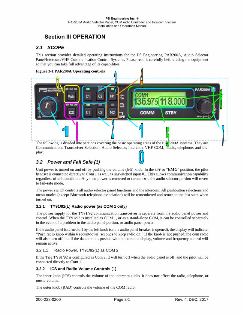
3.2.2 ICS and Radio Volume Controls (1)

The inner knob (ICS) controls the volume of the intercom audio. It does not affect the radio, telephone, or

music volume.

The outer knob (RAD) controls the volume of the COM radio.

PS Engineering Inc. ® PAR200A Audio Selector Panel, COM radio Controller and Intercom System

Installation and Operator’s Manual

200-228-0200 Page 3-2 Rev. 4, DEC. 2017

Adjust the radio and intercom volume for a comfortable listening level. Most general aviation headsets today

have built-in volume controls; therefore, volume also can be further adjusted at the individual headset.

3.3 Communications Transmit (XMT) Selection (2)

The two buttons C1 and C2 (# 2) in the XMT section control which com-

munications radio is selected for transmit. The top row of pushbuttons (# 3)

allows selection of the receiver audio. Push the lower button to select the

desired COM transmitter. A green LED above the button illuminates to in-

dicate that the audio is selected.

The PAR200A-Series has an automatic com receiver selector system. Au-

dio from the selected transceiver is automatically heard in the headsets and

speaker (if selected). You can check this function by switching from Com

1 transmitter to Com 2 transmitter by pressing the COM 2 transmitter selec-

tor pushbutton. See that the associated Com 2 receive pushbutton indicator

light that is located immediately above the Com 2 transmitter pushbutton

turns green. This guarantees that the pilot will always hear the audio from the transceiver selected for trans-

mit.

The PAR200A “remembers” the receiver selection, so that when switching transmitters from COM 1 to COM

2, if COM 2 audio was previously selected, COM 1 audio will continue to be heard. This eliminates the pilot

having to switch Com 1 audio back on, after changing transmitters.

When switching from COM 1 to COM 2 while Com 2 was not previously selected, COM 1 audio will be

switched off. In essence, switching the mic selector will not override prior selection of COM receiver audio.

3.3.1.1 Split Mode

The split mode can be activated at any time by pressing the C1 and C2 XMT buttons at the same time. This

places the pilot on COM 1 and the Copilot on COM 2.

Pilot on COM 2 and Copilot on COM 1 is not possible.

NOTE

Due to the nature of VHF communications signals, and the size constraints in general aviation aircraft, it is

probable that there will be some bleed-over in the Split mode, particularly on adjacent frequencies. PS

Engineering makes no warranty about the suitability of Split Mode in all aircraft conditions.

3.3.1.2 Swap Mode (Switch from Com 1 to Com 2 remotely)

With a yoke mounted, normally open momentary switch, the pilot can change from the current Com trans-

ceiver to the other by depressing this switch. To cancel "Swap Mode," the pilot may either press the yoke

mounted switch again, or select a different Com with the XMT buttons.

3.4 COM Audio Selector (3)

Communication audio from the other radio, not selected for transmit, can be heard by pressing the associated

RCV button. You will always hear the audio from the selected transceiver.

In SPLIT mode, only the pilot will hear selected navigation audio (N1 & N2).

3.5 Navaid Audio selection (4)

VHF Navigation receiver audio is selected through two momentary, push-button, backlit switches.

The users can identify which receivers are selected by noting which green LEDs are lit above the button.

Navigation aid audio push buttons are labeled N1 & N2.

Other audio sources such as Marker Beacon, ADF or DME audio if installed are available if interfaced

through an unswitched input.

3.6 Cockpit Speaker (10)

When the cockpit speaker is turned on, any receiver audio selected will be heard in the speaker. Any un-

switched audio will always be present in the cockpit speaker regardless of the speaker on/off selection.

PS Engineering Inc. ® PAR200A Audio Selector Panel, COM radio Controller and Intercom System

Installation and Operator’s Manual

200-228-0200 Page 3-3 Rev. 4, DEC. 2017

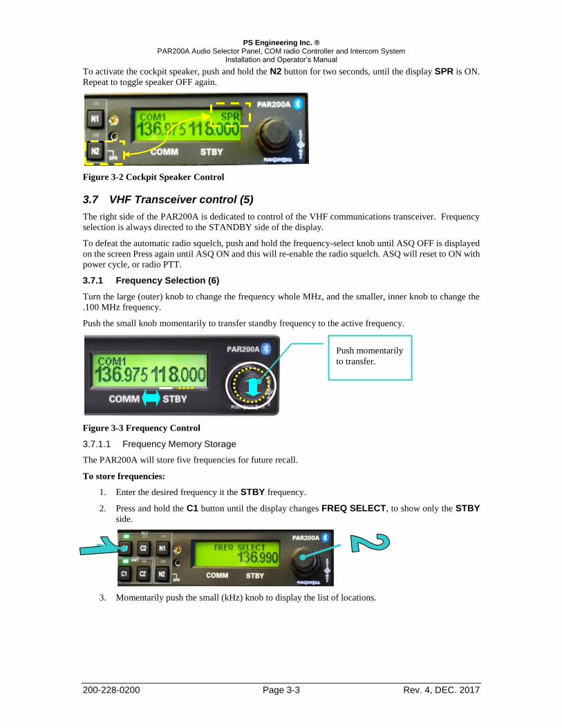
To activate the cockpit speaker, push and hold the N2 button for two seconds, until the display SPR is ON.

Repeat to toggle speaker OFF again.

Figure 3-2 Cockpit Speaker Control

3.7 VHF Transceiver control (5)

The right side of the PAR200A is dedicated to control of the VHF communications transceiver. Frequency

selection is always directed to the STANDBY side of the display.

To defeat the automatic radio squelch, push and hold the frequency-select knob until ASQ OFF is displayed

on the screen Press again until ASQ ON and this will re-enable the radio squelch. ASQ will reset to ON with

power cycle, or radio PTT.

3.7.1 Frequency Selection (6)

Turn the large (outer) knob to change the frequency whole MHz, and the smaller, inner knob to change the

.100 MHz frequency.

Push the small knob momentarily to transfer standby frequency to the active frequency.

Figure 3-3 Frequency Control

3.7.1.1 Frequency Memory Storage

The PAR200A will store five frequencies for future recall.

To store frequencies:

1. Enter the desired frequency it the STBY frequency.

2. Press and hold the C1 button until the display changes FREQ SELECT, to show only the STBY

side.

3. Momentarily push the small (kHz) knob to display the list of locations.

Push momentarily

to transfer.

PS Engineering Inc. ® PAR200A Audio Selector Panel, COM radio Controller and Intercom System

Installation and Operator’s Manual

200-228-0200 Page 3-4 Rev. 4, DEC. 2017

4. Turn the small knob to select the location (1 through 5).

5. Push the small knob again, and the display will revert, and the frequency is stored in that location.

NOTE: If you do not push the small knob, the frequency will not be stored, and reverts to STBY.

To recall stored frequencies:

1. Press and Hold the C2 button until the display changes to FREQ RECALL.

2. Using the small knob, select the desired location in MEM field.

3. Push the small knob to accept this as STBY frequency. NOTE: If you do not push the small knob,

the frequency will not change to the stored, and reverts to STBY.

Figure 3-5 Frequency Recall

3.7.2 Radio Squelch

To defeat the automatic radio squelch, push and hold the frequency knob until the display changes to ASQ OFF, which defeats the squelch and you will hear any weak signals.

Press the right hand side rotary selector knob again until you get the ASQ ON, to restore the Automatic

Squelch.

Figure 3-6 Radio Squelch on/off

3.7.3 Monitor Mode (when PAR200A is COM 1 or stand-alone only)

If the TY91/92 is interfaced as a standalone COM or as COM 1, the radio’s standby frequency monitor can

be used. To activate the monitor mode, press and hold the N1 button until “MON” appears in the display.

PAR200A PAR200A

Figure 3-4 Frequency storage

PS Engineering Inc. ® PAR200A Audio Selector Panel, COM radio Controller and Intercom System

Installation and Operator’s Manual

200-228-0200 Page 3-5 Rev. 4, DEC. 2017

Figure 3-7 Monitor indication

When MON is active, the receiver is tuned to the Standby frequency and passes received audio on that chan-

nel. When the Active frequency receives a signal, the signal from the active frequency is automatically pro-

vided to the audio.

Both active and standby frequencies are monitored at the same time for a signal. A signal can be received on

either the active or the standby frequency.

While receiving a signal on the active frequency - the standby channel is NOT monitored.

While receiving a signal on the standby frequency - the active channel is periodically monitored. If a signal

is found on the active frequency, the TY91/92 will revert to the active frequency. After a signal has been

received, the TY91/92 will return to monitoring both frequencies.

The standby monitoring frequency sends an audible “ticking” to make you aware which is the active &

standby. It will be important to remember which frequency is active and which is standby, to avoid answering

a transmission on the standby frequency by transmitting a response on the active frequency.

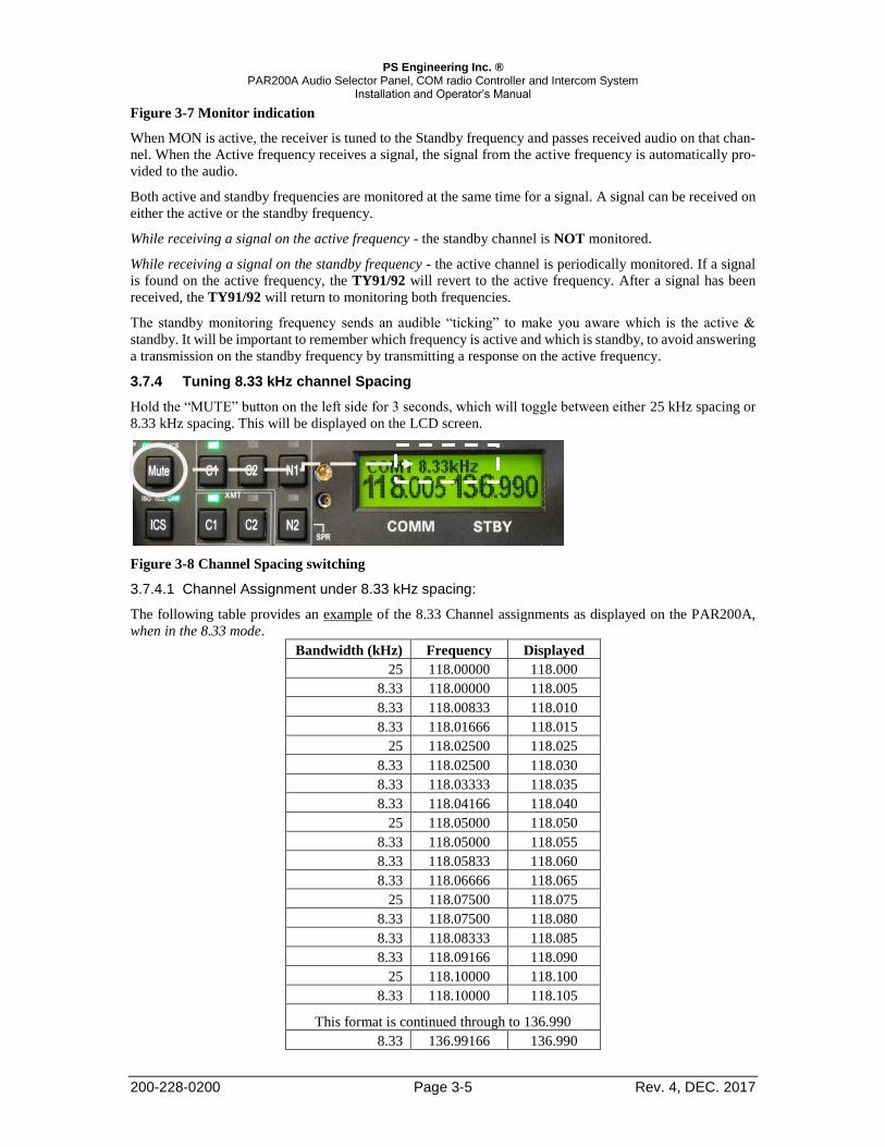
3.7.4 Tuning 8.33 kHz channel Spacing

Hold the “MUTE” button on the left side for 3 seconds, which will toggle between either 25 kHz spacing or

8.33 kHz spacing. This will be displayed on the LCD screen.

Figure 3-8 Channel Spacing switching

3.7.4.1 Channel Assignment under 8.33 kHz spacing:

The following table provides an example of the 8.33 Channel assignments as displayed on the PAR200A,

when in the 8.33 mode.

Bandwidth (kHz) Frequency Displayed

25 118.00000 118.000

8.33 118.00000 118.005

8.33 118.00833 118.010

8.33 118.01666 118.015

25 118.02500 118.025

8.33 118.02500 118.030

8.33 118.03333 118.035

8.33 118.04166 118.040

25 118.05000 118.050

8.33 118.05000 118.055

8.33 118.05833 118.060

8.33 118.06666 118.065

25 118.07500 118.075

8.33 118.07500 118.080

8.33 118.08333 118.085

8.33 118.09166 118.090

25 118.10000 118.100

8.33 118.10000 118.105

This format is continued through to 136.990

8.33 136.99166 136.990

PS Engineering Inc. ® PAR200A Audio Selector Panel, COM radio Controller and Intercom System

Installation and Operator’s Manual

200-228-0200 Page 3-6 Rev. 4, DEC. 2017

3.8 Intercom Operation (8)

3.8.1 IntelliVox® VOX-Squelch

No manual adjustment of the IntelliVox® squelch control is possible. Through individual signal processors,

the ambient noise appearing in all four microphones is constantly being sampled. Non-voice signals are

blocked. When someone speaks, only their microphone circuit opens, placing their voice on the intercom.

The intercom can be configured for high noise environment by internal switching. See § 2.9 for more infor-

mation.

The system is designed to block continuous tones; therefore, people humming or whistling in monotone may

be blocked after a few moments.

For consistent performance, any headset microphone must be placed within ¼-inch of your lips, preferably

against them. (Ref: RTCA/DO-214, 1.3.1.1 (a)).

NOTE

It is also a good idea to keep the microphone out of a direct wind path. Moving your head through a vent air

stream may cause the IntelliVox® to open briefly. This is normal.

The IntelliVox® is designed to work with normal aircraft cabin noise levels (70 dB and above). It loves air-

plane noise! Therefore, it may not recognize speech and clip syllables in a quiet cabin, such as in the

hangar, or without the engine running. This is normal.

For optimum microphone performance, PS Engineering recommends installation of a Microphone Muff Kit

from Oregon Aero (1-800-888-6910). This will not only optimize VOX performance, but will improve the

overall clarity of all your communications.

Table 3-1 Mic Muff ™ Part Numbers

Manufacturer Model Mic Muff™ Part Number

Bose Dynamic

Electret

M87 Dynamic

90010

90015

90020

David Clark H10-30

H10-20, H10-40

H10-13.4

90010

90015

90015

Lightspeed All 90015

Peltor 7003

7004

90010

90015

Pilot 11-20 & 11-90 90015

Sennheiser 90015

Telex Airman 750, Echelon

AIR3000

90015

90010

3.8.2 Mono headsets in Stereo Installation

The pilot and copilot positions work with stereo or mono headsets. All passenger headsets are connected in

parallel. Therefore, if a monaural headset is plugged in to a PAR200A Stereo installation, one channel will

be shorted. Although no damage to the unit will occur, passengers with stereo headsets will only hear in one

ear, unless they switch to the “MONO” mode on their headset.

PS Engineering Inc. ® PAR200A Audio Selector Panel, COM radio Controller and Intercom System

Installation and Operator’s Manual

200-228-0200 Page 3-7 Rev. 4, DEC. 2017

3.8.3 Intercom Modes (8)

The “ICS” pushbutton switch on the left side of the panel provides the selection of

the three intercom modes.

This button cycles through the intercom modes, from left to right, then right to left

as: ISO, ALL CRW and CRW, ALL, ISO. An LED behind the text shows which

mode is currently active.

ISO: The pilot is isolated from the intercom and is connected only to the aircraft

radio system. He will hear the aircraft radio reception (and sidetone during radio transmissions). Copilot will

hear passengers’ intercom and music, while passengers will hear copilot intercom and music. Neither copilot

nor passengers’ stations will hear aircraft radio receptions or pilot transmissions.

When the audio panel is put into the “Split Mode” (pilot on COM 1, copilot on COM 2), the intercom auto-

matically enters the ISO mode to prevent confusion with two intercom conversations. The intercom can be

changed to the CRW or ALL mode if desired.

ALL: All parties will hear the aircraft radio and intercom. Crew and passengers will hear selected music.

During any radio or intercom communications, the music volume automatically decreases. The music volume

increases gradually back to the original level after communications have been completed.

CREW: Pilot and copilot are connected on one intercom channel and have exclusive access to the aircraft

radios. They may also listen to Music 1. Passengers can continue to communicate with themselves without

interrupting the Crew and may listen to music as configured.

3.9 Bluetooth operation

3.9.1 Bluetooth Telephone Connection

Before the PAR200A can be used in TELEPHONE mode with a wireless Bluetooth connection, the unit

must be associated with a specific phone.

Activate the “seek device” function on the cell phone, and then enter the access code “0000” when the

phone detects the “PAR200A” on the list of available devices.

This process will be necessary for any phone to be used, and only one cell phone can be associated with the

audio panel at a time. If the additional phones are associated with the PAR200A at the same time, only the

first phone will transfer audio to the panel.

If the Bluetooth connection fails to reconnect, or becomes unreliable for any reason, you can reset all con-

nections by turning off the PAR200A, holding the N1 and N2 buttons down, and turning the unit back on.

This clears out all paired devices.

PS Engineering recommends this clearing process if you are having difficulties interfacing the PAR200A

audio panel to your Bluetooth phone or device.

3.9.2 Telephone (TEL) Operation

When the Bluetooth-enabled phone receives an incoming call, the PAR200A will play a ring tone. Answer

the call from your telephone handset. The PAR200A exits the telephone mode automatically when the cel-

lular phone hangs up.

In TELEPHONE mode, the pilot microphone and headphones are connected to the cell phone. The pilot

PTT will switch the pilot mic to the selected com transceiver, and allow continued aircraft communications

to continue.

The copilot will also be able to transmit on the other selected radio with his PTT as well.

Entering the TEL mode connects the telephone to the users as follows:

In ALL intercom mode, all crew and passengers will be heard on the phone when they speak. Com and

other selected radio audio are also heard in the headsets. If the pilot or copilot pushes the radio PTT, their

microphone will be transferred to the selected Com radio. The telephone party will not hear ATC commu-

nications, and vice versa. Passengers will not have telephone sidetone and will not hear the ringer.

In CREW mode, only the pilot and copilot are connected to the telephone. Passengers will not hear the

telephone. The pilot and copilot will also have transmit capability on the other selected transceiver.

In ISO intercom mode, when the PAR200A is in the TEL mode, the pilot position is in the "Phone Booth."

PS Engineering Inc. ® PAR200A Audio Selector Panel, COM radio Controller and Intercom System

Installation and Operator’s Manual

200-228-0200 Page 3-8 Rev. 4, DEC. 2017

Only the pilot will hear the telephone, and only he will be heard. He will also have access to Com 1 or 2, and

will transmit on that radio using the PTT. All selected audio is provided to the pilot. Pilot will not have

telephone sidetone in Isolate mode.

NOTE

Because the cell phone uses an intercom circuit, all stations on that circuit will lose intercom capability when

the cell phone is in use.

WARNING

Federal Communications Commission regulation 47 CFR 22.925 prohibits the use of 800MHz Cellular hand-

sets in any aircraft that is airborne. Violation of this rule could result in suspension of service and/or a fine.

3.10 Music Inputs

The PAR200A has two independent music inputs at the rear connector. The PAR200A also has the ability to

receive streaming music from a Bluetooth-enabled device. If both inputs are active, both will be heard in the

headset at the same time, there is not any prioritization.

Music #1 will be normally heard by the pilot and copilot positions ONLY. Music 2 is ONLY available to the

two passenger positions.

Music #1 can also be distributed to the passengers using the rear connector control (See § 2.7.1.1). The

streamed music in the PAR200A is also Music 1.

Music Distribution

Mode

Standard Music

Distribution

Music 1

All Headsets

Music Source

ICS Mode

All Crew ISO All Crew ISO

Music 1 & (Blue-

tooth) Input

Crew Crew Copilot Crew

& Pass.

Crew &

Pass.

Copilot&

Pass.

Music 2 Input Pass. Pass. Pass. NONE NONE NONE

Figure 3-9 Music distribution

NOTE:

All music devices should be turned off for takeoff, landing, or any critical phase of flight. FAA Regulation 14 CFR 91.21

restricts the use of portable electronic devices.

§91.21 “(a) Except as provided in paragraph (b) of this section, no person may operate, nor may any operator or pilot in

command of an aircraft allow the operation of, any portable electronic device on any of the following U.S.-registered

civil aircraft. . .

“(b) (5) Any other portable electronic device that the operator of the aircraft has determined will not cause interference

with the navigation or communication system of the aircraft on which it is to be used.”

You can refer to Advisory Circular 91.21-1A for more information, at http://www.faa.gov

3.10.1 Music Muting (9)

There are two SoftMute™ muting circuits. The front panel "Mute" button has four modes, and con-

trols the Mute function for music 1. Music 2 muting is controlled by an external switch, and has two

modes, mute on and mute off.

The SoftMute™ circuit will cut the music out whenever there is conversation on the radio, the in-

tercom, or both, depending on the “Mute” mode selected. When that conversation stops, the music

returns to the previous level comfortably, over a second or so.

The Music 1 mute functions are controlled through sequential pushes of the Mute button, with LED indication

PS Engineering Inc. ® PAR200A Audio Selector Panel, COM radio Controller and Intercom System

Installation and Operator’s Manual

200-228-0200 Page 3-9 Rev. 4, DEC. 2017

of the mode selected.

MUTE ON - music will mute with either intercom or radio – MUTE ON button is lit.

RADIO MUTE – Intercom will not mute music, radio will mute music. RAD LED indicator is on

INTERCOM MUTE - Radio will not mute music, intercom will mute music - MUTE ICS LED is ON.

MUTE OFF - “Karaoke” mode - music will not mute except during outgoing transmissions. - All Indica-

tors off.

♫ Music Intercom Radio LED INDICATOR

Mute ON Muted Muted ON

Mute OFF ♫ ♫ None

Radio Mute ♫ Muted RAD

ICS Mute Muted ♫ ICS

The passenger’s intercom also has a SoftMute™ circuit. If the passengers hear the radio, or talk on the inter-

com, the music will mute. If the audio panel is in CREW mode, then the radio reception will not affect the

passenger music.

3.10.1.1 Music 2 Mute Control

Passengers also have a Karaoke Mode. If the passengers are listening to the music 2 input, their Karaoke

Mode is activated by an external switch. See § 2.7.2.1.

If the passengers are listening to the Music 1 input, their Karaoke Mode is controlled by the front panel

“Mute” button.

3.10.1.2 Liquid Crystal Display Control

The contrast on the LCD display has been factory set, but you can tweak by using a service adjustment located

inside of the unit. See § 2.9 for adjustment information.

PS Engineering Inc. ® PAR200A Audio Selector Panel, COM radio Controller and Intercom System

Installation and Operator’s Manual

200-228-0200 Page 4-1 Rev. 4, DEC. 2017

Section IV – Warranty and Service

4.1 Warranty

In order for the factory warranty to be valid, the installations must be accomplished under the supervision

of an authorized PS Engineering dealer. If the unit is being installed by a non-certified individual in

an experimental aircraft, a PS Engineering authorized dealer, or factory-made intercom harness must

be used for the warranty to be valid.

PS Engineering, Inc. warrants this product to be free from defect in material and workmanship for a period

of two (2) years from the date of sale. During the two-year warranty period, PS Engineering, Inc., at its

option, will send a replacement unit at our expense if the unit should be determined to be defective after

consultation with a factory technician.

All transportation charges for returning the defective units are the responsibility of the purchaser. All domes-

tic transportation charges for returning the exchange or repaired unit to the purchaser will be borne by PS

Engineering, Inc. The risk of loss or damage to the product is borne by the party making the shipment, unless

the purchaser requests a specific method of shipment. In this case, the purchaser assumes the risk of loss.

This warranty is not transferable. Any implied warranties expire at the expiration date of this warranty. PS

Engineering SHALL NOT BE LIABLE FOR INCIDENTAL OR CONSEQUENTIAL DAMAGES. This

warranty does not cover a defect that has resulted from improper handling, storage or preservation, or unrea-

sonable use or maintenance as determined by us. This warranty is void if there is any attempt to dissemble

this product without factory authorization. This warranty gives you specific legal rights, and you may also

have other rights, which may vary from state to state. Some states do not allow the exclusion of limitation of

incidental or consequential damages, so the above limitation or exclusions may not apply to you.

All items repaired or replaced under this warranty are warranted for the remainder of the original warranty

period. PS Engineering, Inc. reserves the rights to make modifications or improvements to the product with-

out obligation to perform like modifications or improvements to previously manufactured products.

4.2 Factory Service

The units are covered by a two-year limited warranty. See warranty information. Call PS Engineering, Inc.

at (865) 988-9800 before you return any unit. This will allow the service technician to provide any other

suggestions for identifying the problem and recommend possible solutions.

After discussing the problem with the technician and you obtain a Return Authorization Number, ship product

to:

PS Engineering, Inc.

Attn: Service Department

9800 Martel Rd

Lenoir City, TN 37772

(865) 988-9800 FAX (865) 988-6619

Email: [email protected]

Units that arrive without an RMA number, or telephone number for a responsible contact, will be

returned un-repaired. PS Engineering is not responsible for items sent via US Mail.

PS Engineering Inc. ® PAR200A Audio Selector Panel, COM radio Controller and Intercom System

Installation and Operator’s Manual

200-228-0200 Appendix A Rev. 4, DEC. 2017

Appendix A – External PTT Hook Up

Part of the installation includes the installation of PTT (Push to Talk) switches that allow the use of your

aircraft radio for communications transmissions.

There are three possible configurations; you must select the case that best fits your installation.

NOTE: Only the person who presses their PTT switch will be heard over the radio.

CASE I

The PTT is built into the pilot and copilot yokes

Simply install the plugs from the headset into the aircraft headphone jacks. Then use the yoke mounted PTT

to transmit. No other action is required.

CASE II

Built in PTT only on the pilot side only

This configuration requires a modified external PTT switch plugged into the copilot's mic jack. (See Details

Below) When the copilot's PTT is depressed, this activates an internal relay that switches the mic audio to

the aircraft radio from the pilot to the copilot.

Case III

No built in PTT switch at all.

Two built-in PTT must be installed, or two external, modified PTT switches will be required for both the

pilot and copilot. Modifications to the PTT are required. (See details below)

Push To Talk Modifications

When received from the manufacturer, an after-market PTT switch opens the mic audio path to the "ring"

connection of the PTT mic plug until the button is pressed. When the PTT is between the intercom and the

headset, the intercom function will not work unless the PTT switch is depressed. A simple modification can

be performed to allow proper intercom operation. NOTE: This mod does not alter normal operation.

Below are some examples of typical modifications. Contact the PTT manufacturer for more details if neces-

sary.

Procedures for David Clark PTT Unscrew the round black plastic cover from the jack.

Connect the joined black wires to the red wire.

Replace the round black plastic cover.

Procedures for Telex PT-200 Unscrew the round black plastic cover from the jack.

Cut the red wire in the middle of the wire.

Strip both ends of the insulation. Solder the two ends to the ground lug to the PTT jack.

Replace the round black plastic cover.

Procedures for Telex PT-300 Unscrew the round black plastic cover from the plug jack.

Remove the heat shrink material from the joined black wires.

Solder these two wires to the lug that has a white wire already soldered to it.

Replace the round black plastic cover

PS Engineering Inc. ® PAR200A Audio Selector Panel, COM radio Controller and Intercom System

Installation and Operator’s Manual

200-228-0200 Appendix B Rev. 4, DEC. 2017

Appendix B – PAR200A Installation Drawings

J2 J1

Viewed from Back

15

30

44

1

16

31

15

30

44

1

16

31

Ground Lug

Ground Lug475-440-0001 (x2) Back plate assy

475-009-0001ground lug (x2)

475-440-0001 (x2)Screw w/washer

Ground lug detail

Rear plate detail (not to scale)

0.38 in

3.88 in

5.53 in

6.04 in

0.36 in

0.96 in1.28 in

6.31 in

1.28 inRack Installation from Front of Instrument Panel

6.18 in

1.20 inRack Installation from Rear of Instrument PanelMax Panel Thickness 1/8"

PS Engineering Inc. ® PAR200A Audio Selector Panel, COM radio Controller and Intercom System

Installation and Operator’s Manual

200-228-0200 Appendix B Rev. 4, DEC. 2017

Tray and cutout dimensions

Caut ion : Apply s teady pressure to the beze l while screwing the unit into the tray to

ensure even seat ing of the unit and connectors .

6.1 TY91/92 Radio Installation Drawings

Not to Scale. Dimensions in millimeters, (inches)

(6.30)

(1.8

9)

(3.54) (.85)

(5.44)

(Ø.187)

(2.5

2)

(1.2

5)

(1.1

8)

PS Engineering Inc. ® PAR200A Audio Selector Panel, COM radio Controller and Intercom System

Installation and Operator’s Manual

200-228-0200 Appendix D Rev. 2, Sept 2015

Appendix C – J1 Connector Interconnect Figure 7-1 J1 connections, TY91/92(L)-05 as COM 2

Com 1 Audio Hi

Com 1 Mic Key

Com 1 Audio LoCOM 1

Communications

Transceiver

COM 2

Communications

Transceiver

(TY91/TY92 -05)

Nav 1 Audio Hi

Nav 1 Audio LoVHF Nav 1

Nav 2 Audio Hi

Nav 2 Audio LoVHF Nav 2

Unswitched Input #1 Hi

Unswitched Audio Lo

Unswitched Audio #1

Unswitched Input #2 HiUnswitched Audio Lo

Unswitched Audio #2

Pilot Mic Audio Hi

Pilot Mic PTT

Pilot Mic Lo

9

10

11

12

Com 1 Mic Audio Hi

Com 2 Audio Hi

Com 2 Mic Key

Com 2 Audio Lo

13

14

15

30

Com 2 Mic Audio Hi

17

18

19

20

17

29

31

32

44

43

Notes:1. All AUDIO shields should be grounded at audio panel only. Other end remains floating.

Serial Data should be grounded at BOTH ends.

2. PAR200 Power, and Ground wires shall be #22 gage wire

TY91/TY92 Power and Ground shall be 20 AWG minimum

Lighting and TY91/92 interface #22 AWG, other wires minimum #24 AWG

3. All mic and headphone jacks must be isolated from ground.

4. All shielded wires must be MIL 22750 or 27500.

5. Unswitched inputs are always presented to

crew headphones, regardless of SPR switch or PTT.

Unswitched #3 is adjustable

6. TY91 or TY92 interfaced as COM 2.

All connections for TY91/92(L) Radio shown for convenience.

7. Connect J1 25 to J1 26 for TY91/92 as COM 2.

Pilot PTT

PAR200A Connector, J1 (Sub-D 44-pin, male on tray)

Unswitched Input #3 Hi

Unswitched Audio LoUnswitched Audio #3

29

Se

e N

ote

5

Pass . Phones (R)

Pass Phones (L)

Pass . Phones Lo

Pass . 1 PhonesJack

Pass . 2 Phones Jack

22

RS232 RX

RS232 TX

2

1

23

15

6

5

J2

See Note 2, 6

12

30

42

Radi o On

Radi o Power

Radi o Ground

13

12

9

19

24

25

Airframe Ground

5A

Airfr ame Ground25

26

See Note 7

33

34

35

41

40

42

TY91L 11-33

TY92 18-33

Figure 7-2 PAR200A Using TY91/92(L) as COM1 or stand alone

Com 1 Audio Hi

Com 1 Mic Key

Com 1 Audio Lo

COM 2Communications Transceiver

COM 1Communications Transceiver(TY91/92)

9101112

Com 1 Mic Audio Hi

Com 2 Audio Hi

Com 2 Mic Key

Com 2 Audio Lo

13141530

Com 2 Mic Audio Hi

1729123042

RS232 RX

RS232 TX

2 1231565

Radio OnRadio PowerRadio Ground

1312 9192425

J2

J1

2526

NOTE: DO NOT CONNECT

J1-25 to J1-26

to set TY91/92L as COM 1

N/CN/C

PS Engineering Inc. ® PAR200A Audio Selector Panel, COM radio Controller and Intercom System

Installation and Operator’s Manual

200-228-0200 Appendix D Rev. 4, DEC. 2017

Appendix D – J2 Connector Interconnect

20

31

16

1

35

36

24

23

25

4

3

2

Copilo t Phones (R)

Copilo t Phones (L)

Copilo t Phones Lo

Pass. 1 Mic JackPass. Mic Lo

Pass. Mic Hi

37

38Pass. 2 Mic Jack

Pass. Mic Lo

Pass. Mic Hi

32

33

34

Copilo t Mic Audio

Copilo t PTT

Copilo t Mic Lo

Copi lot PT T

Copilot Mic Jack

14

13Ent. #2 Mute

PAR200A J2 CONNECTOR

(Sub-D 44-pin male on tray)

Pass Music

27

26

28

Music #2 Audio (R)

Music #2 Audio (L)

Music #2 Audio Lo

Notes:

Music #1 Audio (R)

Music #1 Audio (L)

Music #1 Audio Lo

Crew Musi c

7

6

5

Copilot

Phones

Jack

Pilot Phones (R)

Pilot Phones (L)

Pilot Phones Lo

Pilot

Phones

Jack

Backlighting

See Sect. 2.4.2

8

9

Grou nd Lu g

A irfra m e Grou nd

11 -3 3 V DC

29

17

44

43

S wa p

S wit ch

S wa p

10

11

1. Al l Power, and Ground wires must be #22 g ag e wire

Li ghting #22 AWG, other wires minimum #24 AWG.

TY91/92 Power and Ground shall be 20AWG.

2. Al l shields should be gr ounded at audio panel only,

other end remai ns floating

3. Pi ns 8 and 9 connected thr oug h a 3 A br eaker

to air cr aft power for the audio panel.

Br eaker s must be pul l-type.

4. Al l shielded wires must be MIL 22750 or 27500.

5. For music di stri bution infor mation, see Sec tion 2.5.1.

6. U se care when connecti ng musi c s ig nal and g round inputs.

Fai lur e to properl y interface music can resul t in

added noise.

D o not connec t M us ic # 1 or M us ic #2 low

to g round. These ar e differential audio inputs .

R efer to 2.4.1.1.

7. C onnec ting J2- 13 to ground ( or J2-13 to J2-14)

will prevent the Musi c 2 input from

muting with i ntercom or radio.

8. C onnec ting J2- 22 to ground ( or J2-22 to J2-14)

pl aces Muisc #1 in al l headsets.

9. Pi n 16 ( pil ot Phones Left) has C OM 1 and

unswitched audi o i n failsafe, and

must be connec ted to the ti p contac t,

and i n a mono installation.

Unswitched Input #4 Hi

Unswitched Audio LoUnswitched Audio #4

15

40

7

6

5

28 V Li ghts Hi

28-Volt lights lo

7

6

5

14 V Li ghts Hi

14-Volt lights lo

See Note 7

3A B rea ke r

See Note 3

Backlighting

See Sect. 2.4.2

RS232 TXD

RS232 RXD

Com mu nic at ion s

T ran sc eiver

(T Y9 1/T Y 92 -05 )

5

6

13

12

9

19

12

30

42

Radi o On

Radi o Power

Radi o Ground

Speak er Hi

Speak er Lo

Cockpit Speaker

22

Music 1 All Headsets

See Note 8

See Note 6

(R) = Right Channel Audio(L) = Left Channel Audio

PS Engineering Inc. ® PAR200A Audio Selector Panel, COM radio Controller and Intercom System

Installation and Operator’s Manual

200-228-0200 Appendix D Rev. 4, DEC. 2017

8.1 Expansion Unit Interconnect (050-228-0202 ONLY)

35

36

37

Expans ion Unit 11636R

Expansion Lo

Expansion Audio Input

Ground Lug10

11

40

41

15

2

3

14

1

Expansion Audio Output (L)

Expansion Audio Output (R)

PAR200A J1

Expansion Power

PAR200A J2

Pass 1 M icPass 1 Mic Audio Hi

Pass 1 Mic Audio Lo

16

4

Pass 2 M icPass 2 Mic Audio Hi

Pass 2 Mic Audio Lo

17

5

1. All wire must conform to MIL-22759 or 27500. Minumum 24 gage shielded wire.2. Use 2-, 3-, and 4-conductor with shield as indicated.3. Use insulating washers on all jacks. Jacks must be electrically floating.4. Connect shields at expansion end only.5. Passenger volume control is adjusted at the audio panel using the outer knob.6. Passenger music input is MUSIC #2 and is located at the audio panel wiring (J2 – pins 26, 27 & 28)7. Passenger music mute control for music #2- press MUTE & AUX on the audio panel at the same time.

8. Passengers can hear Music #1, if J2-22 is grounded through switch.

NOTES:

Pass 1 & 3 Phones (L) Hi

Pass 1 & 3 Phones (R) Hi

Headphone Lo

8

20

Pass 2 & 4 Phones (L) Hi

Pass 2 & 4 Phones (R) Hi

Headphone Lo

9

21

Pass 3 M icPass 3 Mic Audio Hi

Pass 3 Mic Audio Lo

18

6

Pass 4 M icPass 4 Mic Audio Hi

Pass 4 Mic Audio Lo

19

7

23

11

10

Pass 5 M ic

Pass 6 M ic

Pass 5 Mic Audio Hi

Pass 5 Mic Audio Lo

Pass 6 Mic Audio Hi

Pass #1

Pass #3 Headphones

Pass #5

Pass #6Pass #4 Headphones

PS Engineering Inc. ® PAR200A Audio Selector Panel, COM radio Controller and Intercom System

Installation and Operator’s Manual

200-228-0200 Appendix E Rev. 4, DEC. 2017

Appendix E – Instructions for FAA Form 337 and continuing air-worthiness

9.1 Instructions for FAA Form 337, Audio Panels One method of airworthiness approval is through an FAA Form 337, Major Repair and Alteration (Airframe, Powerplant, Propel-

ler, or Appliance) In the case of the PAR200A, you may use the following text as a guide.

Installed audio selector and 6-place intercom, PS Engineering PAR200A, part number 050-228-(XXXX) in ( location ) at

station . Installed per AC43.13-2B, Chapter 2, paragraph 23 (Instrument Panel Mounting). Installed per PS Engineering

Installation Operators Manual p/n 200-228-(XXXX), revision (), dated ( ).

These units are FAA-Approved under TSO C139 for audio amplifiers, and a partial TSO C169a for communications trans-

ceivers, and meets appropriate environmental qualifications outlined in RTCA DO-160G as appropriate for this aircraft.

Interface to existing aircraft radios in accordance with installation manual and in compliance with practices listed in

AC43.13-2B, Chapter 2. All wires are Mil-Spec 22759 or 27500. Connection to aircraft dimmer bus is

____________________. Power is supplied to the unit through a 3A circuit breaker (type and part number), and total elec-

trical load does not exceed % of the electrical system capacity with the PAR200A added.

Aircraft equipment list, weights and balance amended. Compass compensation checked. A copy of the operation instruc-

tions, contained in PS Engineering document 202-228-( ), revision ( ), dated ( ), is placed in the aircraft records. All work

accomplished listed on Work Order .

9.2 Instructions for Continuing Airworthiness, Audio System

Sample ICA Checklist for PS Engineering Audio System: Section Item Information

1 Introduction Installation of audio control panel with integrated VHF communications con-

troller and intercommunications system.

2 Description Installation as described in manufacturer’s installation manual referenced on

FAA Form 337, including interface with other avionics audio as required.

3 Controls See installation and operator’s guide referenced on FAA Form 337.

4 Servicing None Required

5 Maintenance Instructions On Condition, no special instructions

6 Troubleshooting In the event of a unit problem, place the unit into “off,” “fail-safe” and/or

“emergency” mode. This allows pilot communications using COM 1. Follow

checkout instructions in the installation manual referenced on the FAA Form

337. For a specific unit fault, contact the manufacturer at (865) 988-9800 for

special instructions.

7 Removal and replacement infor-

mation

Removal: Using a 3/32” Allen-head wrench, carefully unscrew the locking

screw located in the center of the unit. While turning the wrench CCW, gently

pull on the EDGES of the bezel until the unit is free from the mounting tray.

Installation: Engage the locking screw at the back. Turn the locking screw CW,

while applying slight pressure to the edges of the bezel. Do not over tighten!

8 Diagrams Not applicable

9 Special Inspection Requirements Not Applicable

10 Protective Treatments Not Applicable

11 Structural Data Not Applicable

12 Special Tools None

13 Not Applicable Not Applicable

14 Recommended Overhaul Periods None

15 Airworthiness Limitations Not Applicable

16 Revision To be determined by installer

9.3 ICA for Trig TY91/92 Radio:

Other than for periodic functional checks required by the regulations, the TY91/TY92 VHF radio has been designed

and manufactured to allow “on condition maintenance”. This means that there are no periodic service requirements

necessary to maintain continued airworthiness, and no maintenance is required until the equipment does not properly

perform its intended function. When service is required, a complete performance test should be accomplished fol-

lowing any repair action. Repairs should only be carried out in accordance with Trig Avionics Limited service pro-

cedures.

PS Engineering Inc. ® PAR200A Audio Selector Panel, COM radio Controller and Intercom System

Installation and Operator’s Manual

200-228-0200 Appendix F Rev. 4, DEC. 2017

Appendix F – RTCA DO160G Environmental Qualification Form

Audio Selector Panel/Intercom/Communications Transceiver Controller

Part Number: 050-228-( )

FAA TSO Number: C139, C169a EASA ETSO C139, 2C169a

Manufacturer: PS Engineering Incorporated 9800 Martel Road Lenoir City TN 37772

Conditions Section Conducted Tests

Temperature and Altitude

Low Temperature

High Temperature

In-flight Loss of Cooling

Altitude

Decompression

Overpressure

4.0

4.5.1

4.5.2

4.5.4

4.6.1

4.6.2

4.6.3

Equipment tested to CAT A1 & C1

-55° C Survival, -20°C Low Operating (A1)

-40 Low Short Term Operating

+85°C Survival, +70°C High Short Time Operating + 55˚C

High Operating

Not Applicable, no cooling required

35,000’ unpressurized (C1)

Not Applicable

Not Applicable

Temperature variation 5.2 Equipment tested to Category B (5˚/Minute)

Humidity 6.0 Equipment tested to Category A

Shock 7.0 Equipment tested Standard B

Operational 7.2 Equipment tested to Category E

Crash Safety 7.3 Equipment tested to Category E

Vibration 8.0 Equipment tested to Category S & R

Explosion 9.0 Category X, not tested

Waterproofness 10.0 Category X, not tested

Fluids Susceptibility 11.0 Category X, not tested

Sand and Dust 12.0 Category X, not tested

Fungus 13.0 Category X, not tested

Salt Spray 14.0 Category X, not tested

Magnetic Effect 15.0 Equipment tested to Category Z

Power input 16.0 Equipment tested to Category B(X)(X)

Voltage Spike 17.0 Equipment tested to Category A

Audio Frequency Susceptibility 18.0 Equipment tested to Category B

Induced Frequency Susceptibility 19.0 Equipment tested to Category A

Radio Frequency Susceptibility 20.0 Equipment tested to Category TT

Radio Frequency Emission 21.0 Equipment tested to Category M

Lightning Induced Transient Sus-

ceptibility

22.0 Equipment tested to Category XXA2E2

Lightning Direct Effects 23.0 Category X, not tested

Icing 24.0 Category X, not tested

ESD 25.0 Category X, not tested


Recommended