1 Parachutes for Planetary Entry Systems Juan R. Cruz Exploration Systems Engineering Branch NASA Langley Research Center V13P 2 Overview Slide No. Part I: Introduction 4 Lecture Objectives 5 Scope 6 Further Study 7 Purposes of Aerodynamic Decelerators 9 Historical Review 10 Part II: Parachutes 17 Terminology 18 Types and Functions 24 Stages 35 Drag 36 Dynamics 48 …continued Overview
Transcript
1
Parachutes for
Planetary Entry Systems
Juan R. Cruz
Exploration Systems Engineering Branch
NASA Langley Research Center
V13P
2
Overview
Slide No.
Part I: Introduction 4
Lecture Objectives 5
Scope 6
Further Study 7
Purposes of Aerodynamic Decelerators 9
Historical Review 10
Part II: Parachutes 17
Terminology 18
Types and Functions 24
Stages 35
Drag 36
Dynamics 48
…continued
Overview
3
Overview
Overview
Slide No.
Part II: Parachutes - continued
Deployment 59
Ination 71
Opening Loads 80
Materials 89
Mass and Volume 91
Testing 94
Fluid-Structures Interaction (FSI) Analyses 103
Part III: Additional Materials 104
Symbols 105
Acronyms 108
Glossary 109
Acknowledgements 116
Point of Contact 117
Bibliography 118
4
Slide No.
Part I: Introduction 4
Lecture Objectives 5
Scope 6
Further Study 7
Purposes of Aerodynamic Decelerators 9
Historical Review 10
Introduction
Introduction
5
Lecture Objectives
Introduction: Lecture Objectives
Provide an introduction to the design and analysis ofparachutes for planetary entry systems
- Extensive bibliography provided for more detailedstudy
Target Audience
• Engineers responsible for the development andqualication of such systems
• Program managers and system engineersresponsible for setting requirements and supervisingdevelopment and qualication of such systems
6
Scope
Introduction: Scope
Lectures emphasize topics most relevant to planetaryentry systems, including those for:
- Robotic missions- Precursor human exploration missions- Earth sample return missions- Earth qualication of systems for planetary missions
Topics not emphasized are those only relevant to Earthapplications
Topics not discussed:- Parafoils, inatable aerodynamic decelerators (IAD)- Rigid aerodynamic decelerators (e.g., drag rings)- Systems intended for entry or aerocapture
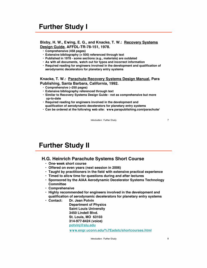
• Extensive bibliography (> 500) referenced through text• Published in 1978 - some sections (e.g., materials) are outdated• As with all documents, watch out for typos and incorrect information• Required reading for engineers involved in the development and qualication of
aerodynamic decelerators for planetary entry systems
Knacke, T. W.: Parachute Recovery Systems Design Manual, Para
Publishing, Santa Barbara, California, 1992.• Comprehensive (~250 pages)
• Extensive bibliography referenced through text• Similar to Recovery Systems Design Guide - not as comprehensive but more
up-to-date• Required reading for engineers involved in the development and
qualication of aerodynamic decelerators for planetary entry systems
• Can be ordered at the following web site: www.parapublishing.com/parachute/
8
Further Study II
Introduction: Further Study
H.G. Heinrich Parachute Systems Short Course• One-week short course
• Offered on even years (next session in 2006)
• Taught by practitioners in the eld with extensive practical experience
• Timed to allow time for questions during and after lectures
• Sponsored by the AIAA Aerodynamic Decelerator Systems Technology
Committee
• Comprehensive• Highly recommended for engineers involved in the development and
qualication of aerodynamic decelerators for planetary entry systems
• Drag can be traded for stability bychanging the gap and band heights
• Appropriate for subsonic andsupersonic applications
• Strong heritage data at supersonicspeeds in low density atmosphereskey to its continued use
• Used by:Viking MPF MPL Beagle 2MER Huygens GenesisStardust
Graphic Source: Ewing, E. G., Bixby, H. W., and Knacke, T. W.:
Recovery System Design Guide, AFFDL-TR-78-151, 1978.
Disk
Gap
Band
34
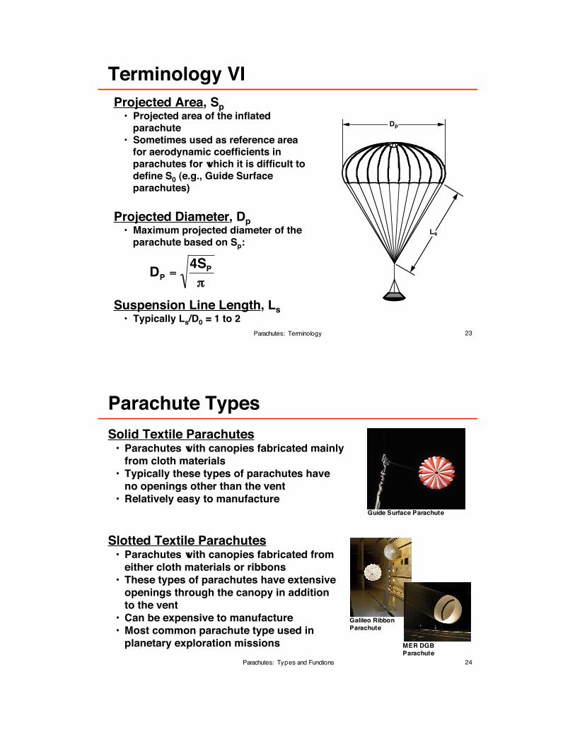
Ringsail Parachutes
Parachutes: Types and Functions
• High drag (CD0 ~ 0.8) with good-to-moderate stability (±5° to ±10° AAO)
• Design tailored for optimum performanceby varying canopy shape and distributionof geometric porosity throughout canopy
• Currently limited to subsonic applications
• Time consuming fabrication
• Relatively light weight per unit drag area
• Used by Beagle 2 and proposed forother missions
Graphic Source: Ewing, E. G., Bixby, H. W., and Knacke, T. W.:
Recovery System Design Guide, AFFDL-TR-78-151, 1978.
35
Stages
DesignQualication
Flight Unit FabricationSterilization
Spacecraft IntegrationLaunch
CruiseEntry
DeploymentInation
DescentRelease
Each stage imposes its own set of requirements andconstraints on the parachute system
Parachutes: Stages
36
Drag - Force parallel to the free-stream velocity, V
Assuming quasi steady-state conditions (e.g.,parachute is fully inated) the parachute drag forceFP can be calculated from:
(using S0 as reference area)
or
(using SP as nominal area)
Drag - Denition
Parachutes: Drag
FP = qCD0S0
FP = qCDPSP
FP
V
37
What does CD0 depend on?
For a specic system (parachute, entry vehicle) in quasi-steady
conditions:
CD0 = f(M, Re, Fr, Kp, c)
where,
Mach Number, M = V / a Reynolds Number, Re = !V L / µ
Froude Number, Fr = V / (L g)1/2 Kaplun Number, Kp = k / ! V2 L
Effective Porosity, c = V! / V*
See “Symbols” section for a denition of all quantities used in this chart
It is difcult to match all these nondimensional quantities in a test!
The Mach Number and Effective Porosity are the most important parameters insituations involving the static aerodynamic coefcients (e.g., CD0) of parachutes
CD0
Parachutes: Drag
38
CD0 vs M
Parachutes: Drag
0.35
0.40
0.45
0.50
0.55
0.60
0.65
CD0
0.0 0.5 1.0 1.5 2.0 2.5 3.0
M
Viking Parachute Wind Tunnel Test Results in Wake of Aeroshell
Sources: Jaremenko, I., Steinberg, S., and Faye-Petersen, R.: Scale Model Test Results of the Viking Parachute System at Mach Numbers from 0.1 Through 2.6, NASA CR-149377, 1971.
Moog, R. D. and Michel, F. C.: Balloon Launched Viking Decelerator Test Program Summary Report, NASA CR-112288, 1973.
39
CD0 vs Fabric Permeability
Parachutes: Drag
Source: Cruz, J. R., Mineck, R. E., Keller, D. F., and Bobskill, M. V: Wind Tunnel Testing of Various Disk-Gap-Band Parachutes, AIAA 2003-2129, 2003.
0.40
0.45
0.50
0.55
0.60
0.1 0.2
CD0
0.3 0.4 0.5
Error Bars at3-Sigma Level
M
1.6 Viking Parachute (Permeable Fabric)
1.6 Viking Parachute (Impermeable Fabric)
The effects of fabric permeability are signicant in many parachutesystems for planetary entry systems - they must be accounted for
40
How does parachute design affect CD0?CD0 Comparison
Canopy Type
• Example: Ringsail parachutes have higher >
CD0 than Guide Surface parachutes
Geometric Porosity
• Parachutes with smaller geometric porosity >
have a higher CD0
• Example: Increasing gap size on a DGB
parachute decreases CD0
Fabric Permeability
• Reducing fabric permeability increases CD0
Design Effects on CD0 I
Parachutes: Drag
0.40
0.45
0.50
0.55
0.60
0.1 0.2
CD0
0.3 0.4 0.5
Error Bars at3-Sigma Level
M
1.6 Viking Parachute (Permeable Fabric)
1.6 Viking Parachute (Impermeable Fabric)
41
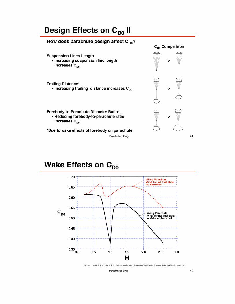
How does parachute design affect CD0?CD0 Comparison
Suspension Lines Length
• Increasing suspension line length >
increases CD0
Trailing Distance*
• Increasing trailing distance increases CD0 >
Forebody-to-Parachute Diameter Ratio*
• Reducing forebody-to-parachute ratio >
increases CD0
*Due to wake effects of forebody on parachute
Design Effects on CD0 II
Parachutes: Drag
42
Wake Effects on CD0
Parachutes: Drag
0.35
0.40
0.45
0.50
0.55
0.60
0.65
0.70
CD0
0.0 0.5 1.0 1.5 2.0 2.5 3.0
Viking ParachuteWind Tunnel Test DataIn Wake of Aeroshell
M
Viking ParachuteWind Tunnel Test DataNo Aeroshell
Source: Moog, R. D. and Michel, F. C.: Balloon Launched Viking Decelerator Test Program Summary Report, NASA CR-112288, 1973.
43
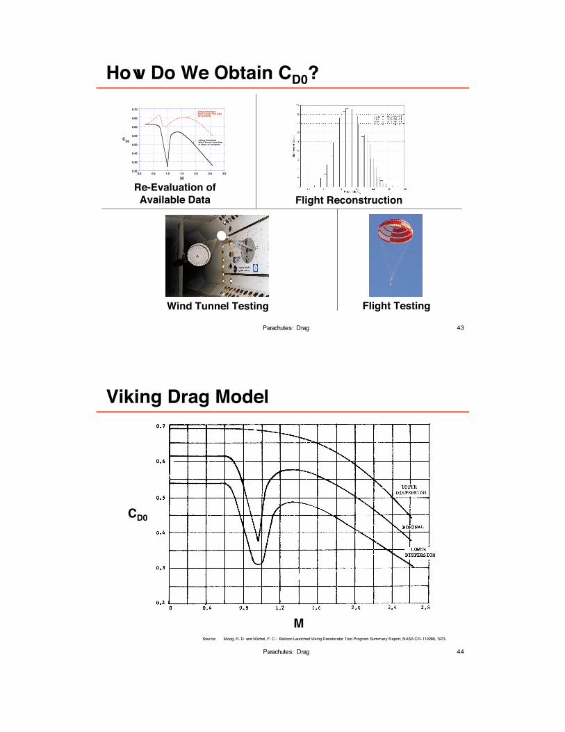
How Do We Obtain CD0?
Parachutes: Drag
Wind Tunnel Testing
Flight Reconstruction
Re-Evaluation of
Available Data
Flight Testing
0.35
0.40
0.45
0.50
0.55
0.60
0.65
0.70
CD0
0.0 0.5 1.0 1.5 2.0 2.5 3.0
Viking ParachuteWind Tunnel Test DataIn Wake of Aeroshell
M
Viking ParachuteWind Tunnel Test DataNo Aeroshell
44
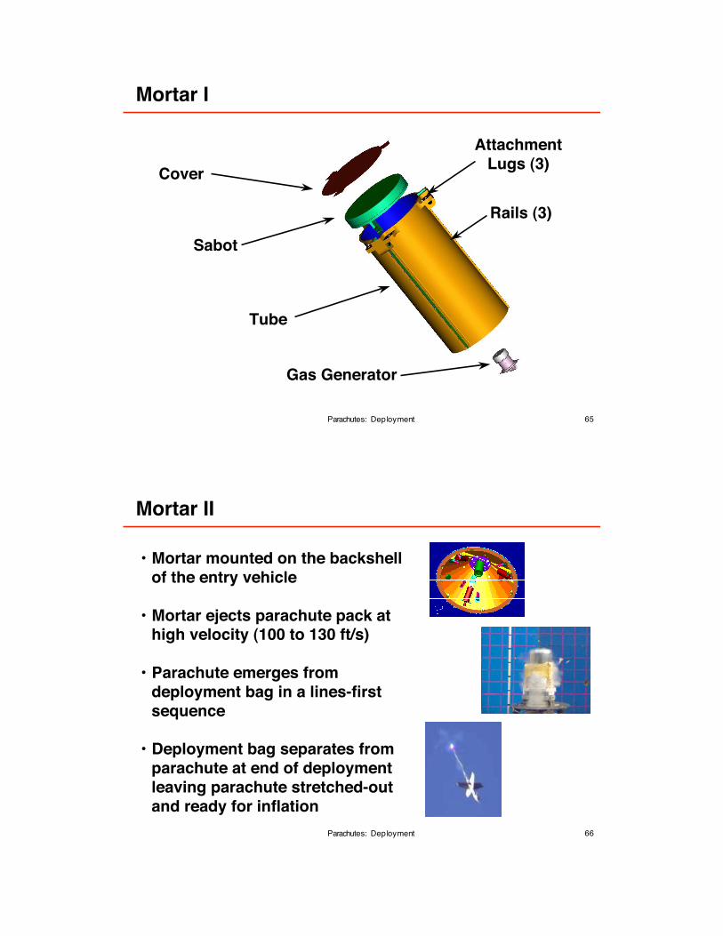
Viking Drag Model
Parachutes: Drag
M
CD0
Source: Moog, R. D. and Michel, F. C.: Balloon Launched Viking Decelerator Test Program Summary Report, NASA CR-112288, 1973.
45
Terminal Descent Problem
Parachutes: Drag
FP + FEV
mg
Basic EquationsFP + FEV = q(CD0S0 + CDEVSEV)
q = ! V2 / 2
FP + FEV = mg
Parachute Sizing - Determine S0CD0, SEV, CDEV, q, m, and g are known
!
S0 = (m g / q - CDEVSEV) / CD0
Terminal Descent Velocity - Calculate VS0, CD0, SEV, CDEV, !, m, and g are known
!V = {2 m g / [! (CD0S0 + CDEVSEV)]}1/2
Parameter Identication - Determine CD0S0, SEV, CDEV, q, m, and g are known
!CD0 = (m g / q - CDEVSEV) / S0
EV
46
2 DOF Trajectory Equations
Parachutes: Drag
m Vx = ! FP +FEV( ) cos!
m Vz = ! FP +FEV( ) sin! ! mg
FP +FEV = q CD0S0 +CDEVSEV
• These trajectory equations can be solved analytically forsome simple cases
• In general, these equations are solved numerically- Start by transforming them into a set of rst-order coupled ordinary
differential equations
- Solve for specied set of initial conditions
V
!
mg
z
x
F + FP EV
47
Parachute Clusters
Parachutes: Drag
Total drag area of a parachute system canbe increased by clustering parachutes
Advantages• Easier to fabricate smaller canopies• Drag area can be adjusted by adding
or deleting canopies• Redundancy• Increased stability• Shorter ination time/distance
Disadvantages• Slight loss of CD0 (~5% for a
three-canopy cluster)• Problems with asynchronous ination• Heavier than a single canopy system
48
Dynamic behavior of the entry system during the parachutephase of descent and landing is important for numerousreasons, for example:
• Scientic observations (imaging)
• Sensor performance (radar)
• Separation events (heatshield)
• Initial conditions for propulsive
terminal descent
• Attitude at rocket ring events
• Control of horizontal velocity
Dynamics - Importance to Planetary Missions
Parachutes: Dynamics
49
Model for Discussion
Parachutes: Dynamics
A simple model will be used for this discussion:
• Parachute and payload behave as asingle unit
• Parachute is modeled as a rigid unit
• Payload generates no aerodynamic forces
• !: angle of attack; single degree of
freedom in this simplied model
• N: parachute normal force acting atparachute center of pressure (CP)
• T: parachute tangential force acting
along axis of symmetry of parachute
• m: parachute pitching moment- Shown about center of gravity, but other referencepoints such as suspension lines conuence pointalso used; do not confuse with mass “m”
• Dynamic derivatives (e.g., , ) are ignoredCm !
!
N
T
CP
V
m
CN !
50
Static Aerodynamic Coefcients
Parachutes: Dynamics
• CN, CT, Cm are static aerodynamic coefcients - functions of !
N = q S0 CN T = q S0 CT m = q S0 D0 Cm
• CT >> CN
• CT dominates drag behavior:
• Center of Pressure function of !
- However, CP assumed constant in present simplied analysis
• Pitching moment coefcient coefcient, Cm, related to CN
where xCP is distance from CP to reference point (typically the system
center of mass or suspension lines conuence point)
• CN and Cm control stability
CD0= C
T
2+C
N
2
Cm= !
xCP
D0
CN
51
Typical CT, CN, and Cm vs !
Parachutes: Dynamics
0.70
0.71
0.72
0.73
0.74
0.75
0.76
0.77
0.78
CT
-20.0 -15.0 -10.0 -5.0 0.0 5.0 10.0 15.0 20.0
! (deg.)
-0.08
-0.06
-0.04
-0.02
0.00
0.02
0.04
0.06
0.08
CN
-20.0 -15.0 -10.0 -5.0 0.0 5.0 10.0 15.0 20.0
! (deg.)
-0.12
-0.08
-0.04
0.00
0.04
0.08
0.12
-20.0 -15.0
Cm
-10.0 -5.0 0.0 5.0 10.0 15.0 20.0
! (deg.)
52
Trim and Stability
Parachutes: Dynamics
-0.12
-0.08
-0.04
0.00
0.04
0.08
0.12
-20.0 -15.0
Cm
-10.0 -5.0 0.0 5.0 10.0 15.0 20.0
! (deg.)
Trim: Cm = 0
Stable Trim Point: dCm/d! < 0 (restoring moment)
Unstable Trim Point: dCm/d! > 0 (diverging moment)
Stable trim points
Unstable trim point
53
Stable and Unstable Parachutes
Parachutes: Dynamics
-0.12
-0.08
-0.04
0.00
0.04
0.08
0.12
-20.0 -15.0
Cm
-10.0 -5.0 0.0 5.0 10.0 15.0 20.0
! (deg.)
“Stable Parachute”Cm = 0 and dCm/d! < 0 at ! = 0
“Unstable Parachute”Cm = 0 and dCm/d! > 0 at ! = 0
54
Possible Motions
Parachutes: Dynamics
• Gliding ight - “constant” !• Oscillation about single trim !• Oscillation from one trim !
to another• Coning• Combination of the above
Other factors further complicate system motions:- Wind shear- Unsteady wake from payload- Payload dynamics- Attachment to payload- Parachute self induced oscillations
-0.12
-0.08
-0.04
0.00
0.04
0.08
0.12
-20.0 -15.0
Cm
-10.0 -5.0 0.0 5.0 10.0 15.0 20.0
! (deg.)
55
Real World Motions - Wind Tunnel Test
Parachutes: Dynamics
56
Real World Motions - MER A Flight
Parachutes: Dynamics
57
Parachute choice and design can be used toaffect stability:
• Guide surface parachute is more stable than
a Ringsail parachute
• Increasing band height on DGB parachutesimproves stability
• Parachute emerges from deployment bag in a lines-rstsequence
• Deployment bag separates fromparachute at end of deploymentleaving parachute stretched-outand ready for ination
67
Drop Test with Mortar Deployment
Parachutes: Deployment
68
Wind Tunnel Test with Mortar Deployment
Parachutes: Deployment
69
Mortar Remarks
Parachutes: Deployment
• Used in all US missions to Mars
• Simple and reliable
• Relatively easy to qualify
• Low bag-strip velocity
• Insensitive to deployment conditions
• High recoil force
• Parachute must be packed to high density (typically 40 to45 lbm/ft3)
• Mortar tube must be long enough to provide sufcient stroke forparachute pack acceleration
- Parachute pack length to diameter ratio 1.0 to 2.5
• Inexible with regards to parachute pack geometry anddimensions
- Can be problematic wrt space allocation inside entry vehicle
70
-10000
-5000
0
5000
10000
15000
20000
Load
(lb)
0 1 2 3 4 5
Time (s)
Load vs Time
6 7
Snatch Loads
Parachutes: Deployment
As the parachute bag re-accelerates to the entry vehiclevelocity, inertial forces are generated
These inertial forces are known as snatch loads
Start of deployment (mortar ring)
Mortar recoil force
Snatch load
End of deployment
& start of ination
Peak opening load
Time from Mortar Firing (s)
Lo
ad
(lb
)
71
Ination
Parachutes: Ination
• Process by which the parachute is
lled (i.e., opens)
• Starts with the parachute stretched-out
and completely out of its deployment
bag, streaming behind the entry vehicle
• Ends with rst full-ination of the
parachute
72
Ination Process
Parachutes: Ination
a) Opening of canopy mouth (start of ination)
Graphic Source: Ewing, E. G., Bixby, H. W., and Knacke, T. W.: Recovery System Design Guide, AFFDL-TR-78-151, 1978.
b) Air mass moves along canopy
c) Air mass reaches crown of canopy
d) Inux of air expands crown
e) Expansion of crown resisted by structural
tension and inertia
f) Enlarged inlet causes rapid lling
g) Skirt over-expanded, crown depressed by momentum of
surrounding air mass
73
Subsonic Ination
Parachutes: Ination
• At subsonic speeds, ination is often modeled as occurring over
a constant number of parachute diameters (i.e., multiples of D0)
for a given parachute type
• Parachute is “scooping” a given volume of air to inate
• For the most part, experimental data supports this assumption
• Thus if ination occurs at a constant velocity, V, the ination
time, tinf, can be estimated from:
tinf = ninf D0 / V
where n depends on the parachute type and geometry (typically
ninf ~ 6 to 15)
• If V varies signicantly during ination, the equations of motion
must be integrated to obtain the ination time for a given ination
distance
74
Supersonic Ination
Parachutes: Ination
• At supersonic speeds, ination is often modeled as occurring
over a xed time, proportional to the parachute diameter but
independent of Mach number (in the range 1.5 ! M ! 2.5)
• For the most part, experimental data supports this assumption
• Thus,
tinf = Kinf D0
where Kinf depends on the parachute type and geometry (for a
Viking-type DGB, Kinf ~ 0.02 s/m)
• Ination (from bag strip to full ination) is very fast at supersonic
speeds! For the Viking DGB with D0 = 16 m, tinf ~ 0.32 s.
75
Innite-Mass Ination
Parachutes: Ination
• If ination is of the innite mass type there will be little deceleration
and reduction in the dynamic pressure during ination
- Peak opening load will occur at full ination
• Innite-mass ination can happen when ination occurs so
rapidly that there is no time for signicant deceleration of the
entry vehicle during ination
• Parachute ination in thin atmospheres at supersonic speeds is
often of the innite mass type -> Mars!
• Innite-mass ination is difcult to obtain at subsonic speeds at
low Earth altitudes - this presents a challenge to the qualication
of supersonic parachutes at low Earth altitudes
• To obtain innite-mass ination at low Earth altitudes:
- Payload mass must be large or,
- Test must be conducted in a wind tunnel
76
-15
-5
5
15
25
35
Lo
ad
/ 1
,00
0
(lb
)q
(ps
f)
0
10
20
30
40
50
-2 0 2 4 6
Time from Mortar Firing (s)
Innite-Mass Ination Example
Parachutes: Ination
Peak opening load
and full ination
q
Load
MER Drop Test - 8,000 lbm Test Vehicle
77
Innite-Mass Ination Film
Parachutes: Ination
78
Finite-Mass Ination
Parachutes: Ination
• If the payload has “nite-mass,” there will be substantial
deceleration and reduction in the dynamic pressure during the
ination
- Peak opening load will not occur at full ination
• This is the typical situation when parachutes are inated at low
Earth altitudes
• It is more difcult to accurately predict the opening loads in a
nite-mass ination
79
Finite-Mass Ination Example
Parachutes: Ination
-10
-5
0
5
10
15L
oad
/ 1
,000 (l
b)
q (p
sf)
20
0
10
20
30
40
50
60
-2 0 2 4
Time from Mortar Firing (s)
6
Full inationPeak opening load
q
Load
MER Drop Test - 3,000 lbm Test Vehicle
80
Opening Loads
Parachutes: Opening Loads
Accurate calculation of opening loads are critical for:• Stress analysis of parachute• Stress analysis of entry vehicle• Calculating acceleration of payload• Specication of on-board accelerometers
Three opening loads analysis methods are discussedhere:
• Panz’s Method• Ination Curve Method• Apparent Mass Method
81
Panz’s Method Description
Parachutes: Opening Loads
• Simple, rst-order, design book type method
• Requires least knowledge of the system as compared to other methods
• Version presented here assumes no gravity - limitsapplication to shallow ight path angles at parachutedeployment (can be extended to account for gravityand steeper ight path angles)
• Neglects entry vehicle drag
• Yields only peak opening load
82
Panz’s Method Equations
Parachutes: Opening Loads
Fpeak = q1 CD0 S0 CX X1
where X1 = f(A, n) and A = 2 mEV / CD0 S0 ! V1 tinf
Variables denition
Fpeak - peak opening load
q1 - dynamic pressure at start of ination
CD0 - parachute full-open drag coefcient
S0 - parachute nominal areaCX - opening load factor (from test data or tables in pages 24 through 26)X1 - force reduction factor accounting for deceleration during ination
(see gure 5-51 of Knacke: Parachute Recovery Systems Design
Manual)
A - ballistic parametern - ination curve exponent (dependent on canopy type, see
Knacke: Parachute Recovery Systems Design Manual, p. 5-58)
mEV - mass of entry vehicle! - atmospheric density
V1 - velocity at start of ination
tinf - ination time (see ination section for guidelines)
83
Panz’s Method Example
Parachutes: Opening Loads
MER A - Spirit
q1 = 729 PaCD0 = 0.400 (at M = 1.75)
D0 = 14.1 mS0 = 156 m2
CX = 1.45
mEV = 827 kg! = 0.00863 kg/m3
V1 = 411 m/s
tinf = 0.282 s (from previous discussion on supersonic ination)
A = 26.5
n = 2 (for DGB parachutes)X1 = 0.98 (i.e., very close to innite mass ination!)
!
Fpeak = 64,641 N (within 10% of best estimate)
84
Ination Curve Method Description
Parachutes: Opening Loads
• An explicit version of Panz’s method
• Assumes a drag area growth function with openingload factor
• Only as accurate as the assumed drag area growthfunction and the opening load factor
• Requires determination of the trajectory
• Easy to implement in trajectory analysis programs
• Yields parachute force-time history
85
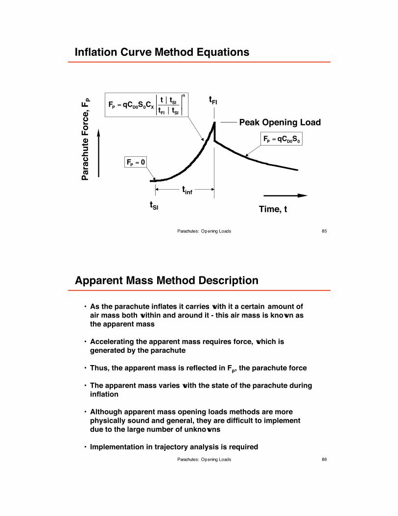
Ination Curve Method Equations
Parachutes: Opening Loads
Para
ch
ute
Fo
rce,F
P
Time, t
tFI
Peak Opening Load
FP= 0
FP = qCD0S0CX
t ! tSItFI ! tSI
!
!!
!
!!
n
FP = qCD0S0
tSI
tinf
86
Apparent Mass Method Description
Parachutes: Opening Loads
• As the parachute inates it carries with it a certain amount of
air mass both within and around it - this air mass is known as
the apparent mass
• Accelerating the apparent mass requires force, which is
generated by the parachute
• Thus, the apparent mass is reected in Fp, the parachute force
• The apparent mass varies with the state of the parachute during
ination
• Although apparent mass opening loads methods are more
physically sound and general, they are difcult to implement
due to the large number of unknowns
• Implementation in trajectory analysis is required
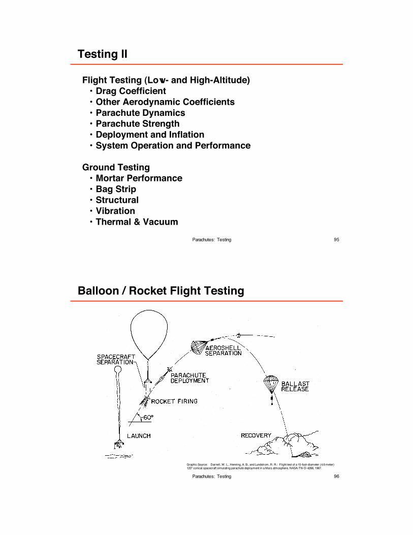
Flight Testing (Low- and High-Altitude)• Drag Coefcient• Other Aerodynamic Coefcients• Parachute Dynamics• Parachute Strength• Deployment and Ination• System Operation and Performance
Graphic Source: Darnell, W. L., Henning, A. B., and Lundstrom, R. R.: Flight test of a 15!foot!diameter (4.6 meter)120° conical spacecraft simulating parachute deployment in a Mars atmosphere, NASA-TN-D-4266, 1967.
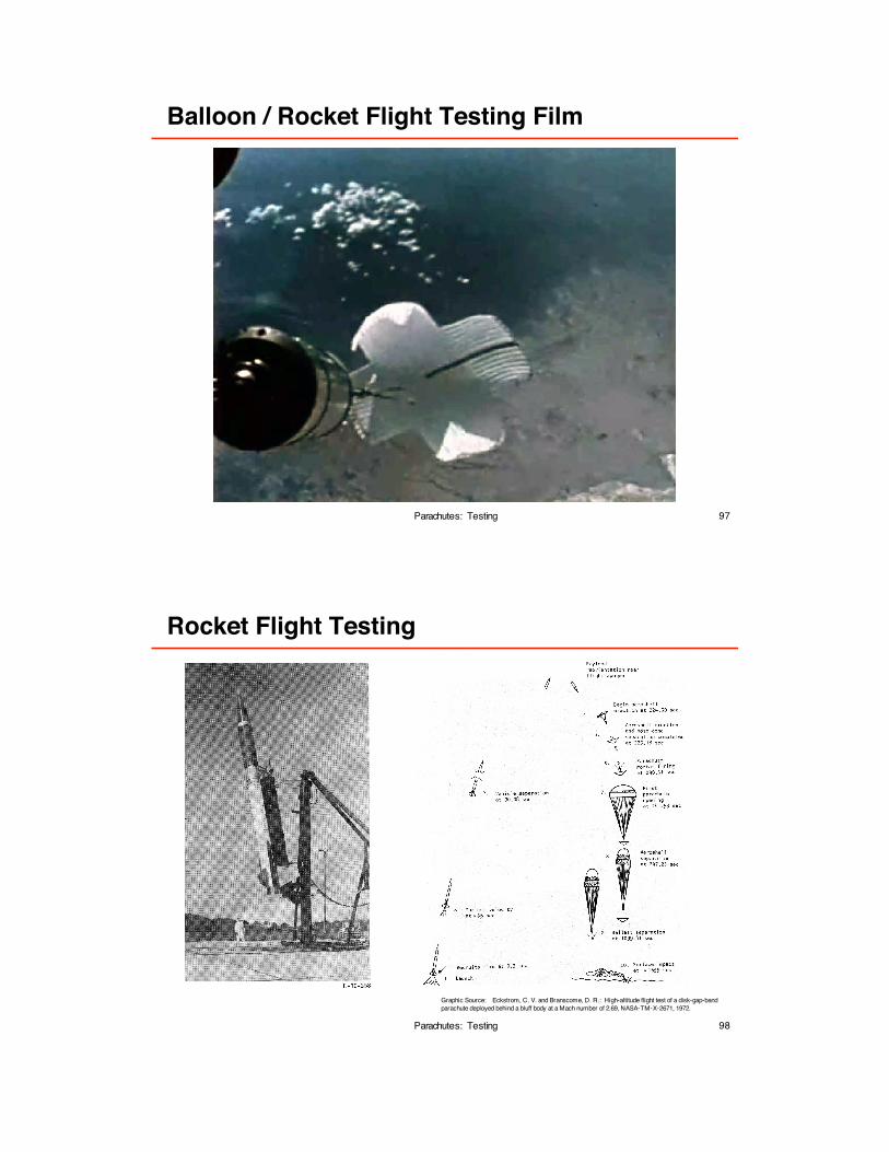
97
Balloon / Rocket Flight Testing Film
Parachutes: Testing
98
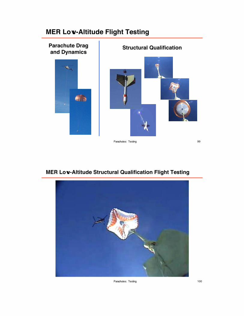
Rocket Flight Testing
Parachutes: Testing
Graphic Source: Eckstrom, C. V. and Branscome, D. R.: High-altitude ight test of a disk-gap-band
parachute deployed behind a bluff body at a Mach number of 2.69, NASA!TM!X!2671, 1972.
99
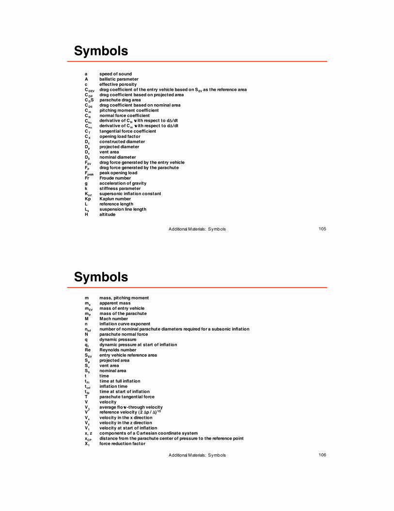
MER Low-Altitude Flight Testing
Parachutes: Testing
Parachute Dragand Dynamics
Structural Qualication
100
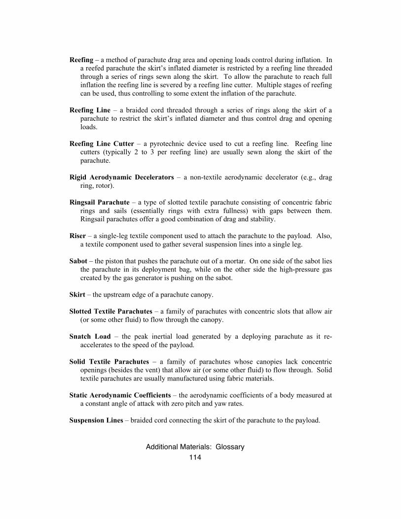
MER Low-Altitude Structural Qualication Flight Testing
Parachutes: Testing
101
MER Sub-Scale Wind Tunnel Testing
Parachutes: Testing
Drag CoefcientAero Static
Stability Coefcients
102
MER Full-Scale Structural Qual Wind Tunnel Testing