Paradoxes in laser heating of plasmonic nanoparticles This article has been downloaded from IOPscience. Please scroll down to see the full text article. 2012 New J. Phys. 14 093022 (http://iopscience.iop.org/1367-2630/14/9/093022) Download details: IP Address: 130.56.107.38 The article was downloaded on 04/11/2012 at 23:25 Please note that terms and conditions apply. View the table of contents for this issue, or go to the journal homepage for more Home Search Collections Journals About Contact us My IOPscience
Transcript
Paradoxes in laser heating of plasmonic nanoparticles
This article has been downloaded from IOPscience. Please scroll down to see the full text article.
2012 New J. Phys. 14 093022
(http://iopscience.iop.org/1367-2630/14/9/093022)
Download details:
IP Address: 130.56.107.38
The article was downloaded on 04/11/2012 at 23:25
Please note that terms and conditions apply.
View the table of contents for this issue, or go to the journal homepage for more
Home Search Collections Journals About Contact us My IOPscience
T h e o p e n – a c c e s s j o u r n a l f o r p h y s i c s
New Journal of Physics
Paradoxes in laser heating of plasmonicnanoparticles
Boris S Luk’yanchuk1, Andrey E Miroshnichenko2,6,Michael I Tribelsky3,4, Yuri S Kivshar2 and Alexei R Khokhlov3,5
1 Data Storage Institute, Agency for Science, Technology and Research,Singapore 117608, Singapore2 Nonlinear Physics Centre, Research School of Physics and Engineering,Australian National University, Canberra, ACT 0200, Australia3 M V Lomonosov Moscow State University, Faculty of Physics,Moscow 119991, Russia4 Moscow State Technical University of Radioengineering,Electronics and Automation (MIREA), Moscow 119454, Russia5 A N Nesmeyanov Institute of Organoelement Compounds,Moscow 119991, RussiaE-mail: [email protected]
New Journal of Physics 14 (2012) 093022 (14pp)Received 21 June 2012Published 13 September 2012Online at http://www.njp.org/doi:10.1088/1367-2630/14/9/093022
Abstract. We study the problem of the laser heating of plasmonic nanoparticlesand demonstrate that, in sharp contrast to the common belief, a particle with asmall dissipative constant absorbs much more energy than the particle with alarge value of this constant. Even higher effective absorption may be achievedfor core–shell nanoparticles. Our analysis uses the exact Mie solutions, andoptimization of the input energy is performed at a fixed fluence with respectto the particle size, wavelength and duration of the laser pulse. We introducea new quantity, the effective absorption coefficient of a particle, which allowsone to compare quantitatively the light absorption by nanoparticles with that of
6 Author to whom any correspondence should be addressed.
Content from this work may be used under the terms of the Creative Commons Attribution-NonCommercial-ShareAlike 3.0 licence. Any further distribution of this work must maintain attribution to the author(s) and the title
a bulk material. We describe a range of parameters where a giant absorptionenhancement can be observed and give practical examples of metals whoseoptical properties vary from weak (potassium) to strong (platinum) dissipation.
Absorption of light by small plasmonic nanoparticles is a key effect for numerous applicationsof nanostructures in data storage technology, nanotechnology, chemistry, biophysics andbioengineering. The absorption characteristics depend on the material of the particle and itsshape. It is relevant to mention the absorption enhancement in amorphous silicon nanoconearrays [1]. The properties of such black silicon are useful for a wide range of commercialdevices. In recent years, the problem of laser heating of plasmonic nanoparticles has attractedmuch attention (see, e.g., [2–11] and references therein). A similar problem appears inastrophysics with thermal noise in interstellar dust where temperature fluctuations for smallparticles of interstellar dust may be about 1000 K [12].
The problem of the effective absorption of light by particles stimulated a great deal ofresearch and posed many non-trivial questions. In one of his famous papers, see [13], Bohrentried to answer the question: ‘how can a particle absorb more than the light incident on it?’. Hewas puzzled by the fact that the absorption cross section may be larger than the geometrical crosssection of the same particle. The answer was quite simple: since the light is an electromagneticwave, a small particle can disturb the flow of electromagnetic energy in its neighborhood and actas a funnel. In this paper, we refine this question and ask: ‘can a particle with a small dissipativeconstant absorb more than one with a large value of this constant?’. By doing a systematicanalysis, we demonstrate that the answer is: ‘yes, it can’; namely, counter-intuitively, in thevicinity of the localized surface plasmon resonances the maximal absorption is achieved at acertain small value of the dissipative constant of the particle. This effect might have a largeimpact on the laser heating and related phenomena.
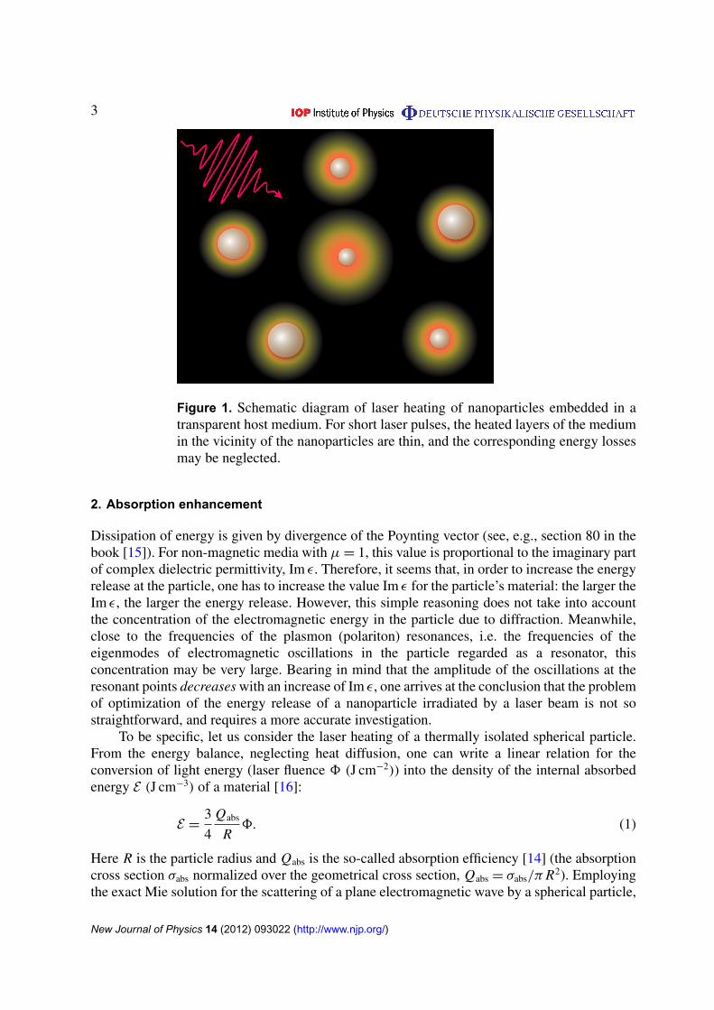
In this paper, we discuss the problem of optimization of the energy input of a laserpulse into a nanoparticle. Our study gives rise to a number of paradoxical, counter-intuitiveconclusions, which shed new light on this important problem. The structure of the paper is asfollows: first, we discuss the origin of the mentioned paradoxes; then, we perform a generalanalysis of the optimization problem based on the exact Mie solution [14]; next, we present theresults of the optimization for six cases of nanoparticles made of different materials; and thenstudy the effect of heat diffusion from a particle to a host medium (figure 1). Finally, in section 5we summarize the obtained results and conclude.
New Journal of Physics 14 (2012) 093022 (http://www.njp.org/)
Figure 1. Schematic diagram of laser heating of nanoparticles embedded in atransparent host medium. For short laser pulses, the heated layers of the mediumin the vicinity of the nanoparticles are thin, and the corresponding energy lossesmay be neglected.
2. Absorption enhancement
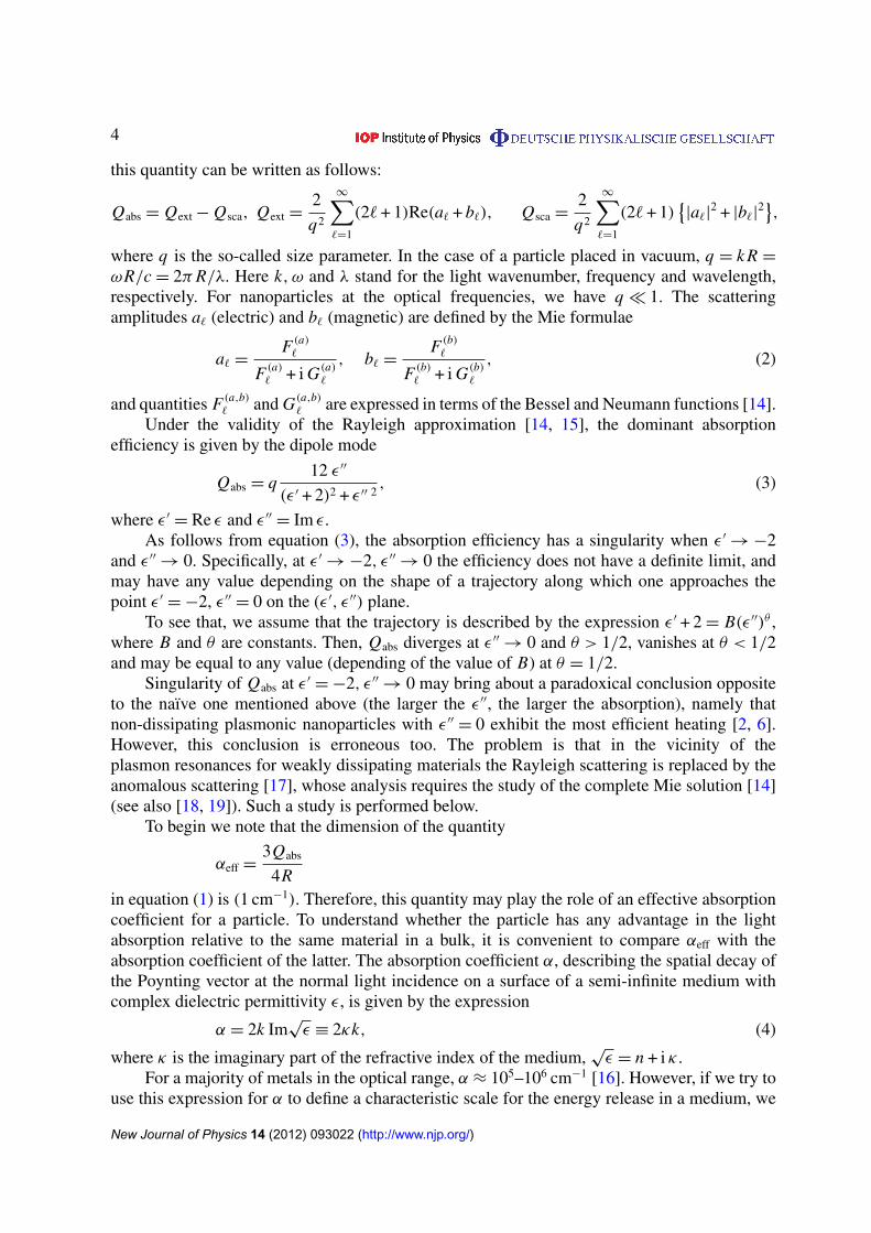
Dissipation of energy is given by divergence of the Poynting vector (see, e.g., section 80 in thebook [15]). For non-magnetic media with µ = 1, this value is proportional to the imaginary partof complex dielectric permittivity, Im ε. Therefore, it seems that, in order to increase the energyrelease at the particle, one has to increase the value Im ε for the particle’s material: the larger theIm ε, the larger the energy release. However, this simple reasoning does not take into accountthe concentration of the electromagnetic energy in the particle due to diffraction. Meanwhile,close to the frequencies of the plasmon (polariton) resonances, i.e. the frequencies of theeigenmodes of electromagnetic oscillations in the particle regarded as a resonator, thisconcentration may be very large. Bearing in mind that the amplitude of the oscillations at theresonant points decreases with an increase of Im ε, one arrives at the conclusion that the problemof optimization of the energy release of a nanoparticle irradiated by a laser beam is not sostraightforward, and requires a more accurate investigation.
To be specific, let us consider the laser heating of a thermally isolated spherical particle.From the energy balance, neglecting heat diffusion, one can write a linear relation for theconversion of light energy (laser fluence 8 (J cm−2)) into the density of the internal absorbedenergy E (J cm−3) of a material [16]:
E =3
4
Qabs
R8. (1)
Here R is the particle radius and Qabs is the so-called absorption efficiency [14] (the absorptioncross section σabs normalized over the geometrical cross section, Qabs = σabs/π R2). Employingthe exact Mie solution for the scattering of a plane electromagnetic wave by a spherical particle,
New Journal of Physics 14 (2012) 093022 (http://www.njp.org/)
where q is the so-called size parameter. In the case of a particle placed in vacuum, q = k R =
ωR/c = 2π R/λ. Here k, ω and λ stand for the light wavenumber, frequency and wavelength,respectively. For nanoparticles at the optical frequencies, we have q � 1. The scatteringamplitudes a` (electric) and b` (magnetic) are defined by the Mie formulae
a` =F (a)
`
F (a)
` + i G(a)
`
, b` =F (b)
`
F (b)
` + i G(b)
`
, (2)
and quantities F (a,b)
` and G(a,b)
` are expressed in terms of the Bessel and Neumann functions [14].Under the validity of the Rayleigh approximation [14, 15], the dominant absorption
efficiency is given by the dipole mode
Qabs = q12 ε ′′
(ε ′ + 2)2 + ε ′′ 2, (3)
where ε ′= Re ε and ε ′′
= Im ε.As follows from equation (3), the absorption efficiency has a singularity when ε ′
→ −2and ε ′′
→ 0. Specifically, at ε ′→ −2, ε ′′
→ 0 the efficiency does not have a definite limit, andmay have any value depending on the shape of a trajectory along which one approaches thepoint ε ′
= −2, ε ′′= 0 on the (ε ′, ε ′′) plane.
To see that, we assume that the trajectory is described by the expression ε ′ + 2 = B(ε ′′)θ ,where B and θ are constants. Then, Qabs diverges at ε ′′
→ 0 and θ > 1/2, vanishes at θ < 1/2and may be equal to any value (depending of the value of B) at θ = 1/2.
Singularity of Qabs at ε ′= −2, ε ′′
→ 0 may bring about a paradoxical conclusion oppositeto the naıve one mentioned above (the larger the ε ′′, the larger the absorption), namely thatnon-dissipating plasmonic nanoparticles with ε ′′
= 0 exhibit the most efficient heating [2, 6].However, this conclusion is erroneous too. The problem is that in the vicinity of theplasmon resonances for weakly dissipating materials the Rayleigh scattering is replaced by theanomalous scattering [17], whose analysis requires the study of the complete Mie solution [14](see also [18, 19]). Such a study is performed below.
To begin we note that the dimension of the quantity
αeff =3Qabs
4Rin equation (1) is (1 cm−1). Therefore, this quantity may play the role of an effective absorptioncoefficient for a particle. To understand whether the particle has any advantage in the lightabsorption relative to the same material in a bulk, it is convenient to compare αeff with theabsorption coefficient of the latter. The absorption coefficient α, describing the spatial decay ofthe Poynting vector at the normal light incidence on a surface of a semi-infinite medium withcomplex dielectric permittivity ε, is given by the expression
α = 2k Im√
ε ≡ 2κk, (4)
where κ is the imaginary part of the refractive index of the medium,√
ε = n + i κ .For a majority of metals in the optical range, α ≈ 105–106 cm−1 [16]. However, if we try to
use this expression for α to define a characteristic scale for the energy release in a medium, we
New Journal of Physics 14 (2012) 093022 (http://www.njp.org/)
face a paradox once more. The paradox is seen clearly if we consider a medium with Re ε < 0and Im ε = 0. Such a medium is non-dissipating, so the energy release there should be zero andobviously does not have any characteristic scale. On the other hand, equation (4) in this caseprovides quite a finite value of α.
The paradox is resolved easily if we recollect that only a part of the incident fluence isabsorbed, while the other part is reflected. Taking into account this fact, one should concludethat, an analogue of equation (1) for the semi-infinite medium in the immediate vicinity of itsboundary reads as
E =Aα8, (5)
whereA stands for absorptivity. In the aforementioned case (Re ε < 0 and Im ε = 0) the particledoes not absorb any radiation,A= 0, and no energy is released in the medium, indeed. If a planeelectromagnetic wave propagating in a vacuum is incident on a medium with complex refractiveindex n + i κ , the absorptivity is given by the following well-known expression:
A=4n
(n + 1)2 + κ2. (6)
In practical cases, A depends also on the quality of the surface, the way it was treated, etc.All these effects may be incorporated into the developed analysis if required. To this end,phenomenological (experimental) values of A should be employed instead of equation (6).
To compare quantitatively the light absorption by the particle and the same bulk material,it is convenient to introduce the net absorption enhancement factor
βeff =β
A, β =
αeff
α, (7)
where A is defined either by equation (6) or by an experimental value. Since 06A6 1,the quantity β presents the minimal value of the absorption enhancement. The condition βeff>β � 1 means that the nanoparticle absorbs light much more efficiently than the correspondingbulk material. To distinguish the role of partial resonances, we introduce also the partialenhancement factors β
(`)
eff and β(`) with replacement in the definition of αeff in equation (7),Qabs → Q(`)
abs, where the partial absorption efficiencies Q(`)
abs read as
Q(`)
abs = Q(`)ext − Q(`)
sca, Q(`)ext =
2
q2(2` + 1)Re(a` + b`), Q(`)
sca =2
q2(2` + 1)(|a`|
2 + |b`|2).
Examples of the dipole (` = 1) and quadrupole (` = 2) plasmon resonances in absorption areshown in figure 2 for the size parameter q = 0.5. From this figure, one can easily find thecorresponding values of the real and imaginary parts of dielectric permittivity ε for each partialresonance.
Similar maxima exist in the absorption efficiencies Q(`)
abs(ε) for all orders of the resonances.For small size parameter q � 1, they follow trajectories of the surface plasmon resonances givenby an approximate formulae [20]:
Re ε ≈ −
[` + 1
`+ q2 2(2` + 1)(` + 1)
`2(2` − 1)(2` + 3)
], Im ε ≈ q2`+1 ` + 1
[`(2` − 1)!!]2 . (8)
The corresponding maximal value of Q(`)
abs at q � 1 is [20]
Q(`)
abs max =1
q2
(` +
1
2
). (9)
New Journal of Physics 14 (2012) 093022 (http://www.njp.org/)
Figure 2. Absorption enhancement β(1) (a), β(2)(b) and total β (c) for the sizeparameter q = 0.5. Calculations are performed in accord with the complete Miesolution for a particle irradiated in a vacuum.
Figure 3. Values of dielectric permittivity corresponding to the maximalabsorption of a nanoparticle irradiated by a plane electromagnetic wave in avacuum versus the size parameter, according to equation (8) and calculated fromthe complete Mie solution: Re ε(q) (a) and Im ε(q) (b). Maximal values of Qabs
and the ratio αeff/α = β along the optimal material parameters (c). The insetin panel (c) illustrates the variation of the coefficient q2 Q(`)
abs max at the maximalabsorption versus the size parameter.
In figure 3, we present the trajectories of these maxima according to the complete Mie solution.Equations (8) and (9) agree excellently with the exact solution up to the size parameter q ≈ 0.5.In figure 3(c) one can see that Q(`)
abs max ∝ q−2, in agreement with equation (9), and β ∝ q−3, inagreement with equations (7) and (9). Deviations of the coefficients from the values definedby equation (8) with an increase in the size parameter are shown in the inset of figure 3(c).Naturally, for larger values of the size parameter, we approach the absorptivity of a bulk
New Journal of Physics 14 (2012) 093022 (http://www.njp.org/)
Figure 4. The Poynting vector distribution in the xz plane for the maximalabsorption in the vicinity of the dipole resonance for particles irradiated in avacuum. The plane, linearly polarized incident wave propagates along the z-axis with the vector E lying in the xz plane. The size parameter q = 0.5 (a)and q = 0.1 (b). For the corresponding values of dielectric permittivity, seefigures 3(a) and (b). Color density plots present the modulus of the Poyntingvector |S|
2 (in log scale). The Poynting vector lines are blue. The surface of theparticle is marked with a black circle. Inside the particle div S < 0; outside theparticle, in free space div S = 0. Red lines in the plots designate separatrixesillustrating the funnel effect [13]. Red circles indicate singular points, namelyone saddle point above the particle, two singular points on the particle surfaceand a few stable nodes inside the particles, which correspond to the positions of‘absorption attractors’. Note the difference in the scales of panels (a) and (b).
material. At the same time, for small values of the size parameter, it is possible to obtain ahuge enhancement in the absorption, e.g. by three or four orders of magnitude, compared to theabsorption of a bulk material (see figure 3(c)). This allows us to term the effect of absorptionenhancement for weakly dissipating plasmonic nanoparticles as the anomalous light absorption.
The physical grounds for the absorption enhancement near the surface plasmon resonancesare related to an increase in the effective cross section of the nanoparticle, which may greatlyexceed its geometrical cross section π R2. The latter can be clearly seen from the Poynting vectordistribution [13, 21–23]. To illustrate the difference in the Poynting vector distributions at themaximal absorption for ‘small’ and ‘large’ particles, in figure 4 we show the correspondingplots for the dipole resonance. Outside the particle in a vacuum div S = 0, while inside theabsorbing particle div S < 0. It allows us to select the whole energy flux into two distinct parts.The Poynting vector lines that penetrate the particle and end inside it belong to one group, andthose that bypass the particle and continue to infinity belong to the other group. The two groupsare separated by separatrixes marked in red in figure 4. A part of the energy flux of the first groupresults in the funnel effect—when the particle acts as an attractor collecting light from a largearea and delivering it to the particle. As a result, the effective absorption area π R2
eff becomesmuch larger than the geometric cross section. The smaller the particle the more pronounced theeffect. In the discussed example (Reff/R)2
≈ 10 at q = 0.5 (figure 4(a)), while at q = 0.1 it isabout 300 (figure 4(b)).
New Journal of Physics 14 (2012) 093022 (http://www.njp.org/)
These results have a simple explanation, namely, owing to the diffractive limit, the maximaldiameter of the ‘funnel’ inlet cannot exceed λ. Then, taking into account that, if ` is not too large,q is the only small parameter in the problem, and that at q � 1 all the three partial resonantcross sections σ
(`)ext max, σ
(`)sca max and σ
(`)
abs max approach certain finite, q-independent limits [17–20],we arrive at the conclusion that the three quantities should be of the same order of magnitude:σ
(`)ext max ∼ σ (`)
sca max ∼ σ(`)
abs max ∼ πλ2/4. It brings about the following estimates:
Q(`)ext max ∼ Q(`)
sca max ∼ Q(`)
abs max ∼ (Reff/R)2∼ (π/q)2,
which agree with the results discussed in the preceding paragraph, see also equation (11) belowand the corresponding expressions in [17–20].
It has been shown above that under the Rayleigh approximation for Qabs, the pointε ′
= −2, ε ′′= 0 is singular. It is interesting to elucidate the actual behavior of Qabs(ε
′, ε ′′) inthe vicinity of this point as well as in the vicinity of the maximum of the anomalous absorptionbased upon the exact Mie solution. Then, a problem about the lineshape for the discussedresonant absorption arises. A general analytical expression for this lineshape has been obtainedin a recent publication of one of the authors [20]. It has been shown therein that the lineshapeof Qabs(ε
′, ε ′′) in the region of anomalous absorption is described by the following universalfunction:
q2 Qabs
2(2` + 1)=
ζ
(1 + ζ )2 + ξ 2, (10)
regardless of the order of the resonance (i.e. the value of `). Here ξ = 1(`)ε ′/ f`(q), ζ = ε ′′/ f`(q)
and 1(`)ε ′ stand for departure of ε from its resonant value, defined by equation (8).Although shapes of the cross sections of the surface defined by equation (10) by the planes
ξ = const and ζ = const are substantially different, in the vicinity of the maximum the surfaceis reduced to the paraboloid of revolution:
q2 Qabs
2(2` + 1)=
1
4−
r 2
16.
Here r 2= ξ 2 + (1ζ)2 and 1ζ denotes a deviation of ζ from the value ζ = 1, where the latter
corresponds to the maximum of Qabs. Regarding the behavior of Qabs at ε ′′→ 0, it is seen
straightforwardly that in this limit Qabs is a linear function of ε ′′ at any fixed ε ′.Completing this section, let us discuss a seeming analogy between the light scattering
of a particle with ε ′′→ 0 and light reflection by an ‘ideal’ conductor, whose conductivity σ
tends to infinity. It seems that an analogy does exist: at σ → ∞ ε ' i ε ′′= i 4πσ/ω → ∞, hence
n = κ =√
ε ′′/2 → ∞ and A→ 0, see equation (6). It means that the ideal conductor reflects100% of incident light and does not absorb any. A particle with ε ′′
= 0 just scatters incidentlight and does not absorb it too. However, the analogy is seeming indeed. Firstly, note thatthese two cases correspond to the opposite limits, since in our case ε is almost purely realwith a small imaginary part. Secondly, the skin-layer δ = 1/α for the ideal conductor vanishing(δ ∼ c/
√σω → 0 at σ → ∞). In contrast, in our case the field penetrates the entire particle,
see figure 5, and all the phenomena discussed above are based upon this effect. The list ofdifferences may be extended. These differences bring about different physics. Thus, in fact,the two phenomena are dissimilar. The analogy between them is forced and may give rise toerroneous conclusions.
New Journal of Physics 14 (2012) 093022 (http://www.njp.org/)
Figure 5. Contour plots for the effective absorption coefficients of differentnanoparticles irradiated in a vacuum.
3. Optimization
It is clear that the discussed huge enhancement in absorption is attractive for many applications.At the same time, in order to obtain this enhancement, one needs an extremely small value ofIm ε; for example, for the dipole resonance at q = 0.1 the corresponding value of Im ε ≈ 10−3,see figure 3(c). The importance of weak dissipation for plasmonic materials was emphasized inmany papers, and some ideas to create weakly dissipating plasmonic materials were suggested(see, for example, [24]). To understand to what extent this reasoning may be applied to naturalmaterials, we performed numerical calculations for six metals: potassium, aluminum, sodium,silver, gold and platinum, whose properties cover a vast range from weak dissipation at theoptical frequencies (potassium) to strong dissipation (platinum). For these calculations, we usethe optical properties of the materials from Palik’s book [25], which are approximated with thehelp of the Drude formula:
ε = ε ′ + i ε ′′= 1 −
ω2p
ω2 + γ 2
(1 − i
γ
ω
), (11)
where ωp and γ stand for the plasma and collision frequencies, respectively. Equation (11) canbe applied to any material provided the plasma and collision frequencies are functions of ω.These functions are calculated at every point in the table [25] with polynomial interpolationbetween the points. The effect of the nanoparticle size was taken into account with the helpof renormalization of the corresponding collision frequency of free electrons, γ = γ∞ + vF/R,where γ∞ is the collision frequency for a bulk material (at a given ω) and vF is the Fermi velocityof electrons [26]. The diffraction problem is treated within the framework of the complete Miesolution. For practical materials, we are more interested in the values of the effective absorptioncoefficient αeff rather than in dimensionless parameters β or βeff. Examples of such calculationsare summarized in table 1. The second column λ0, nm, shows the wavelength where the
New Journal of Physics 14 (2012) 093022 (http://www.njp.org/)
Table 1. Values of the parameters maximizing the absorption of nanoparticlesmade of different metals irradiated by a plane electromagnetic wave in a vacuum.
Fermi velocity, Optimal Optimal αmaxeff , α, cm−1
Metal λ0, nm Im ε(λ0) vF, cm s−1 R, nm λ, nm cm−1 (bulk) A(λoptimal) βeff
infinitesimal particle (q → 0) has the dipole plasmon resonance: Re ε = −2. The third columnindicates Im ε(λ0). This column allows one to distinguish the weakly dissipating materials withIm ε(λ0) � 1 from strongly dissipating with Im ε(λ0) of the order of unity, or larger than that.The values of the Fermi velocity were taken from [27]. The next three columns summarizethe results of calculations of the maximal effective absorption according to the complete Miesolution. We present also the absorption coefficient of the corresponding bulk materials at thewavelengths of the maximal effective absorption of the nanoparticles and the parameter βeff forthe corresponding absorption enhancement with A calculated in accord with equation (6). Asone can see, for weakly dissipating metals (K, Al, Na), it is possible to obtain enhancementin absorption by more than two orders of magnitude. For strongly dissipating materials (Auand Pt), the effective absorption coefficient αeff is even below the absorption coefficient for thebulk material. For Ag with ‘intermediate’ dissipation the ratio αeff/α ≈ 4.6. Nonetheless,the net enhancement factor βeff for Ag is about 20, owing to a small value of absorptivity forthe bulk material. Examples of distributions of the efficient absorption coefficient for a numberof metals in the vicinity of the optimal parameters are shown in figure 5. The dependencesαeff(R, λ) for the other metals are similar. Note that while for weakly dissipating materials thewavelengths, maximizing the absorption and scattering efficiencies, practically coincide witheach other [20] (the difference between them for potassium is less than 1 nm), there exists apronounced mismatch between the two quantities for strongly dissipating materials. Thus, forgold the mismatch is equal to 15 nm.
Note also that for the ‘ideal’ optimization, when ε ′ and ε ′′ may be regarded as twoindependent tuning parameters, αeff increases monotonically with an increase of the order ofresonance `, at least as long as the particle may be regarded as small, see equation (9) andfigure 3. In fact, for the discussed real metals, when instead of ε ′ and ε ′′ the actual tuningparameter is ω the absolute maximum of αeff corresponds to the dipole mode (` = 1).
Bearing in mind that for a thermally isolated particle E = CρT , where C stands for thespecific heat and ρ is the density, it is easy to estimate the fluence 8 which is required toachieve a desired temperature rise, e.g. T = 100 K. It is clear that weakly dissipating particlesneed a smaller fluence than strongly dissipating particles. For instance, to heat a potassiumparticle to the same temperature as a gold particle, we need almost 50 times smaller fluence.Further enhancement of absorption can be achieved for weakly dissipating particles embeddedin transparent media. For example, for K in a KCl host medium at the optimal parameters
New Journal of Physics 14 (2012) 093022 (http://www.njp.org/)
(R = 13.5 nm and λ = 738.6 nm) the effective absorption can reach 6.91 × 106 cm−1. It is about40% larger than that for the same particle in a vacuum and 20 times larger than the absorptioncoefficient for a bulk material. However, the largest increase in the effective absorptioncoefficient may be obtained for a core–shell particle with the optimized core radius, shell radiusand incident wavelength. For K particle inside a KCl shell in a vacuum, it is possible to reachthe effective absorption coefficient 2.05 × 107 cm−1. Such optimized core–shell structures maybe very attractive for biomedical and other applications.
4. Heat transfer
When a nanoparticle is heated inside a host medium, it is important to select a suitable pulseduration for the heating. To this end, one should solve the heat-transfer equation. In our recentpaper [28], this problem was inspected for a broad range of different parameters. However, fora majority of typical cases one can neglect the temperature gradient within the particle andconsider a homogeneous particle temperature rise Tρ(t). In this case, the problem of the laserheating is simplified. For example, we discuss the spherically symmetric problem for a particleembedded in some medium with heat diffusivity χ . We consider a non-absorbing (transparent)medium, which is heated by heat diffusion from the particle solely. The solution of the heatdiffusion equation (see, e.g., [29]) yields
Tp(t) =1
2π i
∫ γ +i∞
γ−i∞Tp(s)e
st ds, (12)
where Tp(s) is the Laplace image
Tp(s) =3
4
I (s)Qabs R
CρR2s + 3κm
(1 + R
√s/χ
) . (13)
Here κm stands for the thermal conductivity of the host medium and I (s) is the Laplaceimage of the laser beam intensity I (t) (W cm−2). For example, for a smooth laser pulse withI (t) = (t/t2
` )8 exp(−t/t`), t > 0 [30], one obtains
I (s) = 81
(1 + st`)2. (14)
The parameter t` in equation (14) is related to the pulse duration tp (full-width at half-maximum)as follows: t` = tp/2.446. The corresponding temperature rise of the nanoparticle may be foundfrom equations (12)–(14) by numerical integration. In figure 6, we show an example of thesecalculations for the temperature rise of a gold particle heated by a smooth laser pulse. It is atypical setup for biomedical applications [31]. We can see that heat transfer to the environmentsuppresses the temperature rise dramatically. To reach temperatures comparable with that forthermally isolated particles, one needs very short laser pulses.
In biomedical applications, it is important to localize the heating area of a host mediumin the immediate vicinity of the nanoparticle. When the particle temperature rise Tρ(t) isknown, the temperature rise distribution in the surrounding medium is given by the followingexpression [29]:
T (r, t) =2
√π
R
r
∫∞
r−R2√
χ t
Tp
(t −
(r − R)2
4χµ2
)e−µ2
dµ, r > R. (15)
New Journal of Physics 14 (2012) 093022 (http://www.njp.org/)
Figure 6. Temperature rise for a gold nanoparticle (R = 21.5 nm) in water, whichcorresponds to the parameters for the maximal effective absorption by a laserpulse with tp = 10 ps and fluence 8 = 236.7 µJ cm−2 (a). The red line presentsthe temperature rise for the thermally isolated particle. The maximal temperaturerise of the particle heated by fluence 8 = 236.7 µJ cm−2 versus pulse durationstp (b).
Figure 7. Temperature rise for a gold nanoparticle (R = 21.5 nm) in water;a laser pulse with tp = 1 ps and fluence 8 = 236.7 µJ cm−2. Different curvescorrespond to different distances r , monotonically varying from r = R to 1.1R.It is seen that the maximal heating decreases sharply with a small increase in r.
Some results of the calculations of the temperature rise profile described by equations (12)–(15)are shown in figure 7.
The huge increase in the effective absorption for a weakly dissipating plasmonic particlein a shell permits us to deliver the laser energy through a thick layer of biological tissue withoutsignificant heating of the tissue itself. In the optical range of the spectrum, the absorptioncoefficient for different tissues varies from αtissue = 10 to 100 cm−1 [32]. This is by a few ordersof magnitude smaller than the effective absorption coefficient which can be reached for weakly
New Journal of Physics 14 (2012) 093022 (http://www.njp.org/)
dissipating plasmonic particles. This permits us to administrate considerable heating of weaklydissipating nanoparticles situated in the tissue in the depth range from 1 mm to 1 cm, dependingon the αtissue value, without damage of the tissue by a laser beam.
The heating may be enhanced considerably if it is produced by an aggregate ofnanoparticles. If the characteristic distance between the particles in the aggregate is sufficientlylong, one may consider the heating effect produced individually by each particle. However, theproblem becomes more complicated when the particles are placed sufficiently close to eachother. In this case, the temperature distribution depends on the number of particles within thecluster [33] and effects related to overlap of thermal fields produced in the host medium by eachindividual particle [34–36]. Another idea to enhance the heating may be based on the black-holeeffect for touching spherical particles [37].
5. Conclusions
Thus, we have obtained a counter-intuitive result that the largest effective absorption coefficientcan be achieved for weakly dissipating plasmonic nanoparticles, in spite of the fact thatthe conversion of the light energy into the internal absorbed energy is proportional to thedissipation parameter Im ε. Our calculations based on the exact Mie solution have revealed thatweakly dissipating plasmonic nanoparticles may exhibit giant absorption enhancement growingproportionally to the inverse cube of the particle size. For example, at the size parameter q = 0.1and optimized values of other parameters of the problem, one can achieve an effective absorptionthree orders of magnitude larger than that for bulk samples. For natural materials, the fulloptimization of absorption cannot be performed because of a fixed dependence of complex ε(ω)
for every given material, which does not allow us to employ Re ε and Im ε as independent tuningparameters. Nonetheless, for nanoparticles made of weakly dissipating metals, the effectiveabsorption coefficient may exceed that for the same bulk materials by two orders of magnitude.It permits us to use efficient heating of nanoparticles embedded in a host medium, e.g. in liquidsor solids. To minimize heat diffusion, very short laser pulses (in typical cases shorter than 10 ps)should be employed. We note that, for the sake of simplicity, in this paper most calculations havebeen performed for a particle irradiated in a vacuum. The calculations can be easily extendedto the case when a particle is embedded in a transparent medium with a purely real refractiveindex nm . To this end, we should just take into account a complex refractive index of the particleas the relative index, namely n → n/nm . We believe that our results may be useful in optimizingmany experiments on laser heating of nanoparticles, and will stimulate further experimentalstudies of this important effect.
Acknowledgments
BL acknowledge funding provided by the SERC Agency of Science, Technology and Research(A*STAR) Superlens Program (project no. 092 154 0099) and the DSI Core Project onNanoparticles. This work was supported by the Australian Research Council through FutureFellowship and Discovery programs and by the Russian Foundation for Basic Research throughgrant no. 12-02-00391-a.
New Journal of Physics 14 (2012) 093022 (http://www.njp.org/)
[1] Zhu J et al 2009 Optical absorption enhancement in amorphous silicon nanowire and nanocone arrays NanoLett. 9 279
[2] Tretyakov S 2003 Analytical Modeling in Applied Electromagnetics (Norwood, MA: Artech House)[3] Govorov A O, Zhang W, Skeini T, Richardson H, Lee J and Kotov N A 2006 Nanoscale Res. Lett. 1 84[4] Govorov A O and Richardson H H 2007 Nano Today 2 30[5] Baffou G, Quidant R and Girard C 2009 Appl. Phys. Lett. 94 153109[6] Khurgin J B and Sun G 2009 J. Opt. Soc. Am. B 26 83[7] Atwater H A and Polman A 2010 Nature Mater. 9 205[8] Baffou G, Quidant R and Garcia de Abajo F J 2010 ACS Nano 4 709[9] Giannini V, Fernandez-Domınguez A I, Heck S C and Maier S A 2011 Chem. Rev. 111 3888
[10] Baffou G and Rigneault H 2011 Phys. Rev. B 84 035415[11] Li X, Hylton N P, Giannini V, Lee K-H, Ekins-Daukes N J and Maier S A 2011 Opt. Express 19 A888[12] Barlett S and Duley W W 1996 Astrophys. J. 464 805[13] Bohren C F 1983 Am. J. Phys. 51 323[14] Bohren C F and Huffman D R 1998 Absorption and Scattering of Light by Small Particles (New York: Wiley)[15] Landau L D, Lifshitz E M and Pitaevskii L P 2002 Electrodynamics of Continuous Media (Oxford:
Butterworth-Heinemann)[16] Bauerle D 2011 Laser Processing and Chemistry 4th edn (Berlin: Springer)[17] Tribelsky M I and Luk’yanchuk B S 2006 Phys. Rev. Lett. 97 263902[18] Gil’denburg V B and Kondrat’ev I G 1965 Radio Eng. Electron. Phys. 10 560[19] Tribel’skii M I 1984 Sov. Phys.—JETP 59 534[20] Tribelsky M I 2011 Europhys. Lett. 94 14004[21] Wang Z B, Luk’yanchuk B S, Hong M H, Lin Y and Chong T C 2004 Phys. Rev. B 70 035418[22] Luk’yanchuk B S and Ternovsky V 2006 Phys. Rev. B 73 235432[23] Luk’yanchuk B S, Tribelsky M I, Terrnovsky V, Wang Z B, Hong M H, Shi L P and Chong T C 2007 J. Opt.
A: Pure Appl. Opt. 9 S294[24] Boltasseva A and Atwater H A 2011 Science 331 290[25] Palik E D 1985 Handbook of Optical Constants of Solids (New York: Academic)[26] Kreibig U and Vollmer M 1995 Optical Properties of Metal Clusters (Berlin: Springer)[27] Kittel C 1996 Introduction to Solid State Physics 7th edn (Hoboken, NJ: Wiley)[28] Tribelsky M I, Miroshnichenko A E, Kivshar Y S, Luk’yanchuk B S and Khokhlov A R 2011 Phys. Rev. X
1 F10001[29] Carslaw H S and Jaeger J C 1959 Conduction of Heat in Solids (Glasgow: Oxford University Press)[30] Arnold N, Luk’yanchuk B and Bityurin N 1998 Appl. Surf. Sci. 127–129 184[31] El-Sayed I H, Huang X and El-Sayed M A 2006 Cancer Lett. 239 129[32] Cheong W F, Prahl S A and Welch A J 1990 IEEE J. Quantum Electron. 26 2166[33] Wang Z B, Luk’yanchuk B, Guo W, Edwardson S, Whitehead D J, Li L, Liu Z and Watkins K G 2008
J. Chem. Phys. 128 094705[34] Tribel’skii M I and Grosberg Yu A 1974 Sov. Phys.—JETP 41 524[35] Tribel’skii M I 1977 Sov. Phys.—JETP 45 172[36] Rodriguez-Oliveros R and Sanchez-Gil J A 2012 Opt. Express 20 621[37] Nerkararyan K V, Nerkararyan S K and Bozhevolnyi S I 2011 Opt. Lett. 36 4311
New Journal of Physics 14 (2012) 093022 (http://www.njp.org/)