Abstract Multiple-Input-Multiple-Output communica-tion systems demand fast sphere decoding with high per-formance. To speed up the computation, we propose ascheme with multiple fixed complexity sphere decod-ers to construct a parallel soft-output fixed complex-ity sphere decoder (PFSD). The proposed decoder ishighly parallel and has performance comparable to soft-output list fixed complexity sphere decoder (LFSD)and K-best sphere decoder. In addition, we proposea parallel QR decomposition algorithm to lower thepreprocessing overhead, and a low complexity LLRalgorithm to allow parallel update of LLR values. Wedemonstrate that the PFSD algorithm can increase thethroughput and reduce bit error rate of a soft-outputsolution in a 4×4 16-QAM system, and has superiorperformance compared to other soft decoders withcomparable throughput and computation complexity.The PFSD algorithm has been mapped onto XilinxXC4VLX160 FPGA. The resulting PFSD decoder canachieve up to 75 Mbps throughput for 4×4 64-QAMconfiguration at 100MHz with low control overhead.
Q. Qi (B) · C. ChakrabartiSchool of Electrical, Computer and Energy Engineering,Arizona State University, Tempe, AZ 85287-5706, USAe-mail: [email protected]
The increasing demand of robust and high through-put mobile systems has spear-headed the developmentof multiple-input multiple-output (MIMO) communi-cation systems. The performance gain of a MIMOsystem comes at the cost of increasing design com-plexity. The signal detector is one of the most impor-tant modules in a MIMO system. Maximum-likelihood(ML) signal detectors are impractical for high datarate MIMO systems, since their complexity increasesexponentially with signal dimension. Active researchon low-complexity and near ML MIMO detectors havegenerated several solutions, including–zero-forcingequalization (ZF) [1], nulling and canceling (NC) [2],semidefinite relaxation (SR) [3, 4] and sphere decod-ing (SD) [5]. Of these approaches, the SD algorithmis the most promising. It offers low complexity andgood bit-error-rate (BER) performance under a vari-ety of Signal-to-Noise (SNR) and constellation condi-tions [6].
The soft-output SD algorithm is favored over thehard output SD algorithm due to its significant perfor-mance gain in low and medium SNR conditions [7]. Asoft-output sphere decoder typically consists of a listgenerator that finds a set of candidate symbol vector,and a log-likelihood (LLR) generator that calculatesthe soft-output bit value for the MIMO channel de-coder. VLSI implementation of SD detectors, such as[7, 8], focus on reducing the computation complexity ofonly the list generator. Recently, a high speed systolic-like soft-output sphere decoder has been proposed in[9]. However, the LLR generator involves sorting largenumber of candidate solutions, and thereby limits thethroughput of the MIMO detector.
218 J Sign Process Syst (2012) 68:217–231
In this paper, we present a new algorithm and ar-chitecture for a soft-output fixed complexity spheredecoder. The main contributions of this paper are listedbelow.
1. We introduce a parallel f ixed complexity spheredecoding (PFSD) algorithm, and investigate its per-formance under different SNR and parallelizationparameters. We find that for a 4×4 16-QAM sys-tem, the PFSD provides better BER performancethan the list fixed complexity decoder (LFSD) [10].
2. We use a parallel QR decomposition algorithm forPFSD that shares intermediate results from multi-ple QR decompositions. As a result, the throughputof this step can be increased by 100% compared toserial QR decomposition, with minimal addition ofcomputation units.
3. We introduce a low complexity LLR algorithm forPFSD that allows parallel update of LLR values. Ithas 85.7% less compare operations than a full listsearch based LLR algorithm.
4. We map PFSD algorithm onto Xilinx XC4VLX160FPGA. It can deliver up to 400 Mbps, 200 Mbpsand 75 Mbps throughput for 4×4 systems with4-, 16- and 64-QAM configuration when clocked at100 MHz.
The rest of the paper is organized as follows. Webriefly describe a MIMO system in Section 2, fol-lowed by a review of the sphere decoding algorithm inSection 3. Section 4 presents the PFSD, the parallelQR decomposition and the low complexity LLR algo-rithms. Section 5 provides algorithm simulation results.Section 6 discusses the hardware architecture for PFSD.The conclusion is given in Section 7.
2 Preliminaries
A basic MIMO Bit-interleaved coded modulation(BICM) communication system [11] consists of chan-nel encoder, interleaver (
∏), modulation and mapping
unit, demodulation and MIMO detector, de-interleaver(∏−1) and channel decoder, as shown in Fig. 1. Assume
that there are MT transmit antennas and MR receiveantennas. Let u denote a vector of uncoded source databits that is input to a channel encoder of rate R≤1to produce a coded bit vector c. The channel encoderoutput vector c is interleaved to obtain bit vector x. Lets be an MR × 1 vector of transmitted symbols. Eachtransmitted symbol is obtained by mapping every Mc =log2(M) consecutive bits from x onto an M-symbol
1nRMn
Info rm atio nSink u
C hannelEnc o d er
Info rm at io nSo urce M od ulatio n
andMap p ing
Soft-outputMIMO
Detector
1 MT
1 MR
H
C hannelDec od er
)(' xL )( xL
u~ c~ x~
s~
y
Π
Π-1
Figure 1 Block diagram of a MIMO communication system.
constellation. Let y be the MR×1 vector of receivedsymbols, given by
y = Hs + n (1)
where H is an MR×MT complex channel matrix, andn is an MR×1 noise vector. Each element hij in Hrepresents the complex transfer function from the jthtransmit antenna to the ith receive antenna. All ele-ments in H are independent and identically distributed(i.i.d.) complex Gaussian variables with zero mean andvariance 1. Similarly, all elements in n are i.i.d. complexGaussian variables with zero mean and σ 2 variance,where σ 2 is calculated according to the received SNR.
A MIMO detector generates a set of symbol candi-dates S = {sSD} according to the following function
sSD = arg mins∈O\S
‖ y − Hs ‖2, sSD ∈ S (2)
where O = MMT denotes all possible transmitted sym-bol vectors which reside in an MT -dimensional squarelattice spanned by an M complex constellation in eachdimension. A set of possible transmitted coded bitvectors {x} is obtained by demodulating symbol set{sSD}. The channel decoder then uses the aposteriorilog-likelihood ratio value (LLR) of the bits from de-interleaved {x} to calculate the likely transmitted datasequence u.
For any received vector y, the low complexity Max-log approximation LLR L(xk|y) for bit xk is calcu-lated as
L(
xk|y)≈ min
x∈Xk,+1
‖ y−Hs‖2
σ 2− min
x∈Xk,−1
‖ y−Hs‖2
σ 2(3)
where s is an MT ×1 symbol vector and x is the corre-sponding MT Mc×1 bit vector. Set Xk,+1 and Xk,−1 de-note subsets of {x} with the kth bit xk =+1 and xk =−1,respectively. Hence, the kth bit LLR of x requires two
J Sign Process Syst (2012) 68:217–231 219
bit vectors with opposite binary values in the kth bit po-sition. One of the bit vectors is always the ML solution.The other bit vector is the complementary solution,whose kth bit is defined as the counter-hypothesis bit[12]. The distance between the hypothesis bit solutionand counter-hypothesis bit solution is a measure of thereliability of the bit value.
Throughout this paper, we assume that the system isfull rank, where MR ≥ MT . The channel matrix H andthe noise variance σ 2 are known to the receiver throughtraining sequence estimation. To generate the maxi-mum likelihood solution, one has to search over MMT
symbol vectors. Even for a moderate 64-QAM 4×4 sys-tem, the complete symbol set {s} contains 16, 777, 216candidates. To avoid exhaustive search, approximateLLRs are calculated by using soft sphere decoding (SD)algorithm, which finds the K smallest norm solutions toEq. 2 in {sSD}, where K � MMT .
3 Sphere Decoding Algorithm
SD algorithms enumerate vector solutions s of Eq. 2,where s ∈ S ⊂ O, and s is inside an ellipsoid centeredat y. To efficiently search the ML solution inside theellipsoid, a SD algorithm converts the original leastsquare problem to a tree search problem using thefollowing steps. It first performs the QR decompositionof the channel matrix H, where H = QR. The result-ing Q is an MR × MR orthogonal matrix, and R isan MR × MT nonsingular upper triangular matrix [6].Equation 2 undergoes orthogonal transformation, andcan be represented as
E =‖ y − Rs ‖2 (4)
where y = QH y = RsZ F . QH denotes the complex con-jugate transpose of Q, sZ F = R−1 QH y = H† y is thezero-forcing (ZF) solution, and H† is the pseudo-inverse of H. We use E to represent the squared dis-tance between estimated and transmitted signals.
Due to the upper triangular nature of matrix R, Eq. 4can be further recursively decomposed to generate thefollowing expressions
‖ y − Rs ‖2 =1∑
i=MT
∣∣∣∣∣∣
⎡
⎣yi −i+1∑
j=MT
rijsj
⎤
⎦ − riisi
∣∣∣∣∣∣
2
=1∑
i=MT
∣∣Vi+1
(s(i+1)
) − riisi∣∣2
=1∑
i=MT
∣∣Di
(s(i)
)∣∣2 (5)
where s(i) = [si si+1 . . . sMT ]T denotes a partial vectorsymbol candidate, Vi+1 is the corresponding residualvector metric and Di(s(i)) is the respective branch metric.The graphic illustration of Eq. 5 is an inverse MT + 1level M-ary tree, where each node has M child nodesexcept the leaf nodes on level 1. Each branch is associ-ated with a branch metric which is always positive. Thepartial Euclidean distance metric (PED), Ti = ∑i
i=MT|
Di(s(i)) |2, is the accumulative branch metrics along apath from the root node to a node at level i, andis monotonically non-decreasing. Note that the siblingnodes have identical PED value Ti+1 and residual vec-tor metric Vi+1.
Existing SD algorithms are based on either thedepth-f irst or breadth-f irst search. The depth-first SDalgorithms, such as the Fincke–Pohst (F–P) algorithm[13] and the Schnorr–Euchner (SE) algorithm [14],generate one candidate solution at a time, and reducethe search radius r based on the current best solution.The K-best algorithm [15] is a type of breadth-firstSD algorithm, where K candidate paths are generatedat a time. From hardware implementation stand-point,the K-best algorithm has several advantages over thedepth-first algorithms, including fixed decoder statetransition, parallel child node extension, and constantthroughput. However, a K-best based algorithm needsto find the K smallest PED paths out of KM can-didate paths at each decoding level, which requireslarge number of sorting operations for moderate K andM. This issue is circumvented by fixed complexity SDalgorithms [16–19].
Fixed complexity SD algorithms are breadth-first SDalgorithms that generate a set of transmitted vectors bytraversing fixed paths from the root level to the leaflevel. The entire tree search procedure is defined by thecardinality vector t = [t1, t2, . . . , tMT ]. At level i, eachparent node enumerates ti child nodes in increasingorder of their branch metrics. Fixed complexity SDalgorithms eliminate the sorting procedure by keepingall expanded nodes. The resulting number of partialvector candidate s(i) is
∏MTj=i tj, where 1 ≤ tj ≤ M. The
cardinality vector t and symbol detection order cangreatly impact the performance of a fixed complexitySD algorithm. The algorithm in [16] offers an effectivesolution, and it is denoted as the fixed-complexity SD(FSD) algorithm in the following sections.
The FSD algorithm consists of three steps, namely,channel matrix ordering, solution set generation andhard decision selection. Channel matrix ordering deter-mines the order in which the symbols in vector s aredetected. Solution set generation finds solution candi-date vectors according to a predefined n. Hard decisionselection finds the candidate vector with the smallest
220 J Sign Process Syst (2012) 68:217–231
PED value. FSD only has two types of node expansions,full expansion (FS) and single expansion (SS). In FS, aparent node expands and keeps all M child nodes. InSS, only the child node with the smallest branch metricis kept. The top p levels of solution set generation areof type FS, and the remaining MT − p levels are oftype SS. The symbols in consecutive FS levels are de-tected in ascending order of their post-detection noiseamplification, and the symbols in consecutive SS levelsare detected in descending order of their post-detectionnoise amplification.
We developed a soft-output parallel fixed complex-ity SD (PFSD) algorithm based on the hard-outputFSD algorithm, which not only delivers high through-put but also offers good scalability. The PFSD algo-rithm details are described in the following section. A
Table 1 Definition of key notations.
Notation Definition
Di Branch metric at level iE Distance between estimated and transmitted signalsEi Path metric set for Si
Ex0
i,bmin Minimum path metric for the bth bit in Xi
with value 0H† Pseudo-inverse of HHi Column-wise permuted H according to kiki ith permutation vectorki,l lth element of kil LLR value vector for sM QAM constellation sizeM Cardinality value for tMT
Mc Bits per M-QAM symbolt Child node cardinality vectornj Child nodes per parent node at level jQ Orthogonal matrixq j,l lth column of Qj
R Upper triangular matrixr Sphere decoder search radiuss Candidate symbol vectorS A set of candidate symbol vectorsSi A subset of S generated from Hi and y
isi A candidate symbol at level is(i) Partial vector symbols contains elements si to sMT
sML Maximum likelihood symbol vectorsZ F Zero forcing solutionsi, j jth symbol vector in Si
si, j,MT MT th symbol of jth symbol vector in Si
Ti Partial distance metric from root node to anode at level i
Vi Residual vector metric for level ix Candidate bit vectorXi Bit vector equivalence of Si
x0i,b , j bth bit of the jth bit vector in Xi with bit value of 0
y Received symbol vectory
iOrthogonal transformation of y
summary of the key notations that are used in this paperis included in Table 1 for easy reference.
4 Parallel Fixed Complexity Sphere Decoding
The fixed complexity SD algorithms are best suitedfor VLSI implementation due to simplification in pathpruning in the solution generation steps [18]. However,existing soft decision fixed complexity sphere decod-ing algorithms [10, 20] provide high diversity in thebit values by either selective child node enumeration,or expansion of larger number of child nodes in suc-cessive levels. Both procedures introduce data depen-dency between sibling nodes, and require additionalcomputation. We propose a high throughput parallelfixed complexity sphere decoding (PFSD) algorithmwhich eliminates this dependency by producing softdecision outputs from multiple hard decision FSDs.The PFSD algorithm provides good BER performancewhen compared to a LFSD algorithm with similar com-putation complexity. In addition, the PFSD algorithmmake use of layer ordering technique in [21] to reducepreprocessing overhead. Last, the PFSD algorithm pro-duces more reliable LLR values with slight increasein computation overhead than a competing parallelfixed complexity sphere decoding algorithm, LayeredOrthogonal Decoding (LORD) in [22].
The proposed PFSD algorithm is presented inAlgorithm 1. It starts with the same channel matrixordering step as the FSD algorithm in [16] and producesa 1 × MT permutation vector k1. Additional MT − 1permutation vectors are derived from k1 iteratively(lines 2–5). Vector ki must guarantee that its last ele-ment ki,MT
differs from k j,MTfor all i = j. A new Hi
is obtained by column-wise permutation of the originalH according to ki. In the solution set generation step,PFSD produces candidate set Si for each pair of Hi
and y by performing FSD search with cardinality vectorti = [1, 1, . . . , M] (lines 9–15). Hence, there are MT
candidate sets and each set has M vectors. Note thatwhen ti,MT
= M = M, the first decoding level is fullyexpanded. It can be relaxed to a partial expansion level(ti,MT
< M) to reduce overall computation complexity.However, this results in performance degradation asdemonstrated in the simulation results in Section 5.Finally, PFSD finds the quasi-ML solution sML andcalculates the 1 × Mc MT LLR vector l from MT Mvector candidates (lines 19 and 20). The LORD algo-rithm also uses multiple FSDs to generate candidatesolution set. However, it differs in the way multiple QRdecomposition are done (Section 4.1) as well as the wayLLR values are calculated (Section 4.2).
J Sign Process Syst (2012) 68:217–231 221
Algorithm 1 Soft decision PFSD algorithmRequire: M, MT , y, H
k1,MT ]3: for i = 2 to MT do4: Construct ki, where ki,MT
= k j,MT, ∀ j < i
5: end for6: {Solution Set Generation:}7: Set S = ∅8: for i = 1 to MT do9: Generate Hi by permuting H column-wise ac-
cording to ki10: [Qi, Ri] = qr(Hi), y
i= QH
i y
11: ti = [1, . . . , 1, M], M ≤ M12: {FSD tree search:}13: Input: Ri, y
i, ti; Output: Solution subset Si
14: Inverse permute candidate vectors in Si using ki15: S = Si ∪ S
16: end for17: {Calculate Outputs:}18: Assign minimum weight vector in S to sML
19: Calculate LLR values l from S
20: return hard and soft decision outputs
Essentially, PFSD produces soft decision outputs byperforming multiple hard decision FSDs. The theoret-ical analysis in [23] proves that FSD can provide thesame diversity order as the ML decoder, and yieldasymptotically ML performance in the high SNR regionunder the following condition
(MR − MT) (q + 1) + (q + 1)2 > MR (6)
where q is the number of FS levels. For a 4×4 MIMOsystem, 1 FS level is sufficient (ti = [1, . . . , 1, M]).The symbol detection order of each FSD in PFSD isuniquely determined by its permutation vector. Ele-ment ki,MT specifies the 1st detected symbol of the ithFSD. Since ki,MT differs from kj,MT provided i = j, eachsymbol element of vector s becomes the 1st detectedsymbol exactly once. In case partial expansion is used,where tMT = M < M, M must be sufficiently large toguarantee the existence of counter-hypothesis bit ateach bit position. This condition improves the reliabilityof LLRs. Note that the number of candidate nodes ateach level is uniform, and the number of calculationsinvolved in finding all candidate vectors is identical.
The complexity analysis of PFSD includes that of thechannel matrix ordering step and the tree search step.The channel matrix ordering step is identical to theFSD algorithm. Since the tree search step is equivalent
to multiple FSD decoding, the computation complexityof the tree search step is simply MT times the complex-ity of one stage full expansion FSD implementation.However, the PFSD requires multiple QR decomposi-tions, which adds computation complexity to the overallalgorithm. In the next subsection, we present a parallelQR decomposition algorithm that can generate outputsof two H matrices every cycle, thereby reducing theoverhead. The multiplication complexity of the treesearch step, without including the QR decompositionoverhead, is given by
Nmult = MT
MT∑
i=1
[aM + (MT − i)b M
](7)
where a denotes the number of real multiplications forl2-norm calculations of branch metric (a is typically 2),and b denotes the number of real multiplications fora complex product (b is typically 3 or 4 dependingon the implementation). It is easy to see that Nmult
only depends on MT and M. For a given modulationscheme, Nmult increases cubically with MT ; for a fixedantenna system, Nmult increases linearly with respect tothe modulation size.
4.1 Parallel QR Decomposition for PFSD
To support multiple tree searches in PFSD, a QRdecomposition is needed for each FSD. We presenta parallel QR decomposition algorithm based on [21]that lowers channel processing overhead by combiningthe channel matrix ordering with QR decomposition.For instance, for a 4×4 system, if matrices Hi and Hj
differ only in the two right most columns, the com-mon intermediate results generated during their QRdecompositions can be shared, resulting in significantcomputation saving. The permutation vectors for 4×4serial and parallel QR decompositions are illustrated inFig. 2a. Alphabets a–d are used to denote the valuesof permutation vector kj, 1< j<4. In parallel QR, forvector k1 and k2, the first two columns of H1 and H2
are the same. Similarly for vectors k3 and k4, the firsttwo columns of H3 and H4 are the same. Hence, theyshare identical decomposition results, and redundantcomputation steps can be avoided. Figure 2b showsthe permutation vectors for 8×8 system. For example,first four columns of H1–H4 (H5 through H8) shareidentical decomposition results, and their permutationvector elements a–d (h through g) have same colorfilling. Finally, existing QR decomposition systems arebased on Given Rotations [24] and Householder trans-formation [25]. Unfortunately, those methods cannot
222 J Sign Process Syst (2012) 68:217–231
1 2 3 4 5 6 7 8
k 1 a b c d e f g h
k 2 h b c d e f g a
k 3 h a c d e f g b
k 4 h a b d e f g c
k 5 h a b c e f g d
k 6 h a b c d f g e
k 7 h a b c d e g f
k 8 h a b c d e f g
1 2 3 4 5 6 7 8
k1 a b c d e f g h
k2 a b c d e f h g
k3 a b c d h g f e
k4 a b c d h g e f
k5 h e f g a b d c
k6 h e f g a b c d
k7 h e f g c d b a
k8 h e f g c d a b
1 2 3 4
k 1 a b c dk 2 a b d c
k 3 d c b a
k 4 d c a b
Serial QR 8x 8 Parallel QR 8x8
Serial QR 4x4
Parallel QR 4x4
1 2 3 4k 1 a b c d
k 2 d b c a
k 3 d a c bk 4 d a b c
(a) (b)
Figure 2 Permutation order comparison of serial QR and paral-lel QR decompositions for a 4×4 and b 8×8 channel matrices.
be easily extended to exploit the common computationsand result in large overhead.
The parallel QR decomposition is shown inAlgorithm 2. We use the improved sorted Gram-Schmidt QR decomposition algorithm in [26], wherethe 2nd minimum norm square |qj|2 is chosen for ki fori ≥ 2. As a result, H1 satisfies the channel matrix order-ing for FSD but incurs additional compare and vectorl2 norm operations. This is useful for hard decisiondecoding under very high SNR conditions, where theminimum weight solution generated from H1 is almostalways the transmitted vector. However, simulation re-sults in Section 5.1 show that channel matrix orderingstep has negligible performance impact on PFSD, andcan be excluded to reduce computation complexity.
Figure 3 shows the data flow graphs (DFG) of Gram-Schmidt method for both serial and parallel QR decom-position. In both cases, two 4×4 channel matrices H1 =[h1, h2, h3, h4] and H2 =[h1, h2, h4, h3] are fed as in-puts, and two orthonormal matrices Q1 =[q
1, q
2, q
3, q
4]
and Q2 =[q1, q
2, q′
3, q′
4] are produced as outputs. Both
Algorithm 2 Parallel QR Decomposition algorithm1: {Channel Matrix Order (optional)}2: Perform improved sorted Gram-Schmidt QR de-
composition [26] for H1
3: Generate permutation vector k14: for j = 2 to MT do5: Generate permutation vector kj from k j−1 {See
parallel QR channel matrix examples in Fig. 3}6: Obtain Hj by column-wise permuting H accord-
ing to kj7: Perform QR decomposition on Hj {Copying
shared intermediate results from previous QR}8: end for
DFGs consist of two types of nodes, N and P. NodeN takes an input vector ain and produces a normalizedbasis vector eout which is passed to the P node below.Node P has two inputs, ain and ein, and two outputs,aout and eout. eout is set to ein and passed to the Pbelow; aout is computed by subtracting the subspacecomponent of ain in the direction of basis ein, and passedto the node to its right. All input and output vectorsare complex. The elements in the R matrix (of the QRdecomposition) are a by-product of the computation inthe P and N nodes. Essentially, rij in R is the Hermitianinner product between ein,i and ain, j.
For the 4×4 system, node P requires 24 real mul-tiplications, 47 real additions, and node N requires 16real multiplications, 7 real additions, 1 real division and1 real square-root. If we assume that each node takes1 cycle, then the parallel QR produces the outputs ofQ1 and Q2 in cycles 5–8. Since it is a pipelined imple-mentation, the next set of outputs (corresponding to Q3
and Q4) can be produced in cycles 6–9. In contrast, thepipelined implementation of the serial QR producesoutputs of Q1 and Q2 in cycles 5–9 and outputs of Q3
Figure 3 Data flow graphsfor: a serial QR and b parallelQR decompositions for 4×4channel matrix.
N
P N
P P N
P P P N
h1
h2
h3
h4
h1
h2
h4
h3
q'4q'3
q1
q4
q1
N
P N
P P N
P P P N
h1
h2
h3
h4
N
P ND
D D
D
P
ein
ain
eout
aout Nain
eout
ain
eout = -------- ||ain||
eout = ein
aout = ain - <ein,ain>ain
t1t2t3t4t5 t1t2t3
t5
t6
t7
t8
t9
t5
t6
t7
t8
(a) (b)
q2
q2 q3
q1
q2
q3 q'3
q4 q'4
J Sign Process Syst (2012) 68:217–231 223
and Q4 in cycles 7–11. Note there is a 3 cycle latencyoverhead for the 1st QR decomposition and after thatthe parallel QR produces outputs at twice the rate asthe serial QR. For MR×MR matrix, the parallel QRonly requires one additional P node and two additionalN nodes more than the serial QR to achieve the 100%throughput gain.
The parallel QR algorithm not only has reducedthe computation complexity, but also has lower mem-ory storage requirement compared to performing eachQR decomposition independently in parallel. The twochannel matrices Hi and Hj derived from permutingchannel matrix H, differ in last two columns. The QRdecomposition results of Hi and Hj show that Qi and Qj
differ in the last two columns and Ri and Rj differ in lasttwo rows. Hence, memory requirement of the parallelQR decomposition results does not increase linearlywith respect to antenna size. For the 4×4 system, thememory requirement of the parallel QR algorithm isonly 2.8X more than a single QR decomposition, andis 30% less than performing each QR decompositionindependently in parallel. For the 8×8 system, thememory requirement of the parallel QR algorithm is3.6X more than a single QR decomposition, and is 55%less than performing each QR decomposition indepen-dently in parallel.
4.2 Low Complexity LLR Algorithm for PFSD
Generating LLR values from a large list of candidatesymbol vectors contribute significantly to the compu-tation complexity to the overall soft-output decoding.The proposed low complexity LLR algorithm for PFSDproduces suboptimal soft-output values for a given setof candidate vectors in order to reduce the number ofsorting operations. Equation 3 shows that to calculatethe LLR for one bit position, we need the the quasi-MLsolution, and the counter-hypothesis bit solution. Thelow complexity LLR algorithm searches all candidatevectors for the quasi-ML solution. However, it onlysearches a subset of candidate vectors for each counter-hypothesis bit solution. Furthermore, since candidatevector subsets are independent from each other, LLRvalues can be computed in parallel without compromis-ing the quasi-ML solution. The proposed algorithm issummarized in Algorithm 3.
The low complexity LLR algorithm starts by re-ceiving MT subsets of candidate symbol vectors (Si)and their path metrics (Ei) from the PFSD solutiongeneration step. The algorithm searches and saves min-
imum PED values E x0i,b
min and E x1i,b
min within Ei. The M(MT −1) symbol candidate vectors from other subsets are
2: sML =[ ], l0 =[ ], l1 =[ ], EML = ∞3: for i = 1 to MT do {for Xi}4: for b = 1 to Mc do {for xi,b , j}5: if xi,b , j ==0 then
6: E x0i,b
min = min j=1,...,M E x0i,b , j , E x0
i,b , j ∈Ei, x0i,b , j ∈Xi
7: add E x0i,b
min to l0
8: else9: E x1
i,b
min = min j=1,...,M E x1i,b , j , E x1
i,b , j ∈Ei, x1i,b , j ∈Xi
10: add E x1i,b
min to l1
11: end if12: EML = min(E x0
i,b
min, Ex1
i,b
min, EML)
13: kML =ki, sML =sEML
, sEML ∈S
i, if EML changes14: end for15: end for16: inverse permute sML using kML
17: xML =demod(sML)
18: update l0 and l1 using xML and EML
19: calculate LLR l= l0−l1
20: return sML, EML and LLR values
ignored. However, the quasi-ML solution is selectedfrom all MMT vectors. The ith bit vector subset Xi isobtained by only demodulating si, j,MT in Si (see line 1).Variable si, j,MT denotes the MT th symbol element ofthe jth symbol vector, where 1≤ j≤ M. The algorithm
then searches and saves minimum path metrics E x0i,b
min
and E x1i,b
min associated with subset Xi (see lines 5–11). Theb th bit of the jth bit vector is denoted by xi,b , j, where1≤b ≤ Mc; x0
i,b , j and x1i,b , j represents xi,b , j with bit value
0 and 1 respectively, and their PED values are denotedby E x0
i,b , j and E x1i,b , j . Vector l0 and l1 records newly found
E x0i,b
min and E x1i,b
min . The quasi-ML solution sML is updated
along with its permutation vector kML when either E x0i,b
min
or E x1i,b
min is smaller than its current path metric EML
(see lines 12 and 13). LLR values l are finally calcu-lated using properly permuted sML, l0 and l1 (see lines16–19).
The low complexity LLR algorithm performs sub-optimal search of the counter-hypothesis bits, and full
search of the quasi-ML bits. Since E x0i,b
min and E x1i,b
min are gen-erated locally for the MT th symbol within the ith FSD,the number of compare operations can be reduced byexploiting the property of QAM symbols. Recall thatsymbols in the same column share identical in-phase
224 J Sign Process Syst (2012) 68:217–231
binary code and symbols in the same row share iden-tical quadrature binary code. Hence, path metrics forsymbols with identical in-phase and quadrature compo-nents are minimized first. Then, minimum path metrics
E x0i,b
min and E x1i,b
min are generated for the b th bit position
from surviving path metrics, which also require 2�√
M�symbol demodulations. The total number of compareoperations for the low complexity LLR algorithm isgiven by
Ncomp =[2MT
(M − 1
)M
]+
[MT Mc
(M − 2
)]
+ [2MT − 1] (8)
where M=�√
M�, M≤ M. The first term in Eq. 8 cal-culates the number of quadrature and in-phase symbolpath metric comparisons. The second term calculatesthe number of bit position path metric comparisons.The last term counts the additional compare opera-tions for the quasi-ML solution. Parallel implementa-tion of the compare operations require 2MT M sortingnetworks of size MT , MT Mc sorting networks of size(M−1) and 1 sorting network of size 2MT . For a 4×4system, the sorting networks are not very large, andyet they contribute to 14% of the decoder area in ourFPGA implementation!
Existing methods such as K-best and LFSD arebased on full search of counter-hypothesis bits. Whenall MMT symbol candidate vectors are consideredin a full counter-hypothesis bit search, additionalMT Mc[(MT − 1)M] compare operations are requiredto find the bit values. For a 4×4 system, this translatesto 85% and 88% less compare operations compared tothe full search algorithm for 16-QAM and 64-QAM,respectively.
5 Simulation Results
In this section, we compare the Monte-Carlo simulationresults of PFSD, LFSD and K-best sphere decodingalgorithms. The system under investigation consistsof MT =4 transmit and MR =4 receive antennas. Theuncoded source data vector u is 4,096 bits long. It isencoded by a parallel concatenated Turbo encoder,which consists of two component Rc =1/2 RecursiveSystematic Convolutional (RSC) component encoders.The generator matrices for the encoders are g1(D) =1 + D + D2 and g2(D) = 1 + D2 [27]. The output ofthe encoder c is a 8,192 bits long packet. Each packetis passed through a pseudo-random interleaver, andreshaped to a 4×2,048 bit matrix. Gray code map-ping is used to map every Mc = 4 consecutive bits in
each row to a 16-QAM symbol. A vector of 4 sym-bols is transmitted at a time, one from each antenna.Block Rayleigh fading is used to model the channel.We assume that the channel matrix H is known, andstays constant for every 16 consecutively transmittedsymbol vectors. The fading coefficients hijs of H areindependent and identically-distributed (i.i.d.) complexunit variance Gaussian variables.
The energy per transmitted information bit isdefined as Eb = 1, and the noise power is calculatedfrom a given SNR Eb/N0|db with σ 2 = N0. There areRc Mc bits in a transmitted symbol, and the averagesymbol energy per transmit antenna is defined as Es =Rc Mc Eb . Hence, the total energy per received antennais MT Es. The MIMO detector calculates the soft-valueinformation using the Max-log approximation for eachreceived symbol vector. The LLR clipping values of ±8are used for a prescribed bit when no counter-hypothesis bit is found in the candidate solution set [28].Each LLR is a signed 10-bit long number with 6 bitsin the fractional part. The Turbo decoder consists oftwo parallel concatenated soft-output Viterbi algorithm(SOVA) based decoders.
The Turbo decoder takes the soft outputs from theMIMO detector, and decodes the information bits it-eratively. Eight iterations are run for each packet. ForBER less than 10−2, simulations are kept running untilat least 1,000 bit errors are accumulated at the outputs.For BER greater than 10−2, simulations are kept run-ning until at least 100 bit errors are accumulated at theoutputs.
5.1 BER Performance
Figure 4a shows the BER performance of LFSD, PFSD,LORD and K-best decoders for a 4×4 system with16-QAM modulations. The LFSD algorithm is a soft-output extension of the FSD algorithm [10], where thenumber of expanded nodes doubles for p levels afterthe initial q FS levels. Hence, the cardinality vector tfor 64 candidate LFSD decoder is [1, 2, 2, 16] with q=1and p=2. We study 2 setups for the PFSD decoder,with 64 total candidates but different LLR computationcomplexities. The first uses the low complexity LLRalgorithm described in Section 4.2. The other, denotedas the max-log LLR, computes LLR values at each bitposition from all 64 candidate solution. Finally, the 64candidate LORD algorithm [22] is added for baselineperformance comparison.
The SNR differences of these algorithms are ex-amined at 10−3 BER. The PFSD with parallel QR(pQR) and exact max-log LLR computation providesthe best performance at 3.3 dB SNR. This is due to the
Figure 4 BER performance comparison of: a the K-best, the LFSD, the LORD and the PFSD algorithms and b the PFSD algorithmwith different candidate cardinality vectors and QR decomposition setups with a rate Rc = 1/2 Turbo code and 16-QAM modulation.
existence of counter-hypothesis bits for all bit positionsin their candidates solution set. The LFSD and theK-best decoders can not make such a claim. They useLLR clipping when necessary, which affects the qualityof the soft bit values for the channel decoder, and inturn, the BER [29]. The LFSD and the K-best decodersachieve 10−3 BER at 3.6 dB and 3.8 dB, respectively.The PFSDs with low complexity LLR closely follow theK-best decoder. They achieve 10−3 BER slightly below4dB. In low complexity LLR, the counter-hypothesisbit squared Euclidian distance is calculated from 1
MT
candidate vectors in the candidate set. This providessignificant savings in terms of number of sorting op-erations at the expense of small BER degradation.The LORD algorithm also uses 1
MTcandidate lists to
compute LLR values at all bit positions; however itdoes not find the exact quasi-ML solution. Hence, theoverall quality of its LLR values is lower than PFSDwith low complexity LLR.
Figure 4b shows the BER performances of the PFSDalgorithm with low complexity LLR for different QRdecomposition, initial channel ordering and cardinalityvectors. We study 3 setups for PFSD with 64 candidates,(i) parallel QR (pQR) with initial channel ordering[16] for the first FSD, (ii) pQR without initial chan-nel ordering, and (iii) serial QR (sQR), as shown inFig. 2, for all MT QR decompositions. For these threesetups, the SNR differences are less than 0.1 dB. Theseresults illustrate that initial channel ordering and QRdecomposition scheme have little effect on the PFSDalgorithm. Multiple FSDs reduce the likelihood that
unfavorable channel ordering from any one FSD domi-nates the overall performance of PFSD. We concludethat PFSD can be implemented without performingthe initial channel ordering to reduce preprocessingcomputation overhead.
Figure 4b also shows the effect of different numberof nodes expanded at the top level of each FSD inPFSD. PFSD with 64 and 48 total candidates achieves10−3 BER at 3.98 dB and 4.3 dB, respectively. PFSDwith 48 candidate vectors provides better performancethan LORD with 64 candidate vectors. The number ofnodes expanded at the top level has significant impact,because less nodes expanded at the top layer increasethe likelihood that the correct symbol will be missedat the top decoding layer of each FSD, and reduce thelikelihood that symbols at lower layers will be detectedcorrectly.
5.2 Computation Complexity
For high throughput applications, in addition to BERperformance, the computation complexity as well asthe overhead of parallelization are important metrics.Table 2 shows the operation costs of aforementionedalgorithms measured in terms of number of additions,multiplications and comparisons. Among the candidatealgorithms, LFSD (64:[1,2,2,16]) has the lowest numberof multiplications and K-best has the highest numberof multiplications. The proposed PFSD with 64 and 48candidates has 1.3–1.6 times more multiplications thanLFSD, but 10–33% less multiplications than the K-best.
226 J Sign Process Syst (2012) 68:217–231
Table 2 Comparison of SDalgorithms with respect toperformance and complexity.
Algorithms for 4 × 4 SNR for Number of operations
16-QAM system 10−3 BER Addition Multiplication Comparison
Even though PFSD has more multiplications thanLFSD, its candidate vectors are independent of eachother and they can be generated in parallel. In contrast,in LFSD, the sibling candidate nodes are partially de-pendent on each other in intermediate decoding stages.This data dependency translates to additional compu-tations [30], and increases decoder latency for largerantenna system with more intricate cardinality vectorsetup.
All these algorithms require comparisons for thesorting operations in solution set generation and LLRvalue calculation. The two PFSDs and LORD have sim-ilar number of comparisons for LLR value calculation,but LFSD and K-best have significantly higher num-ber of comparisons. The PFSD implementation con-sists of MT identical sorting networks and 1 quasi-MLpath sorter. Each parallel sorting network requires atmost [2(
√M − 1)
√M] + [Mc(
√M − 2)] comparators;
the quasi-ML path sorter requires 2(MT − 1) com-parators. Hence, sorting networks for PFSD scale wellwith respect to increasing QAM size and antennaconfiguration. The sorting operations in LFSD and K-best depend on total number of candidate vectors andare typically implemented by a folded network whichincreases the latency of the LLR computation.
6 FPGA Implementation of PFSD
In this section, we discuss the hardware implementationdetails of the PFSD decoder for a 4 × 4 MIMO system.In the channel preprocessing part, we do not considerchannel matrix ordering since it does not enhance theperformance. The parallel QR architecture is based onFig. 3b, where each P node is implemented with 6 realmultipliers and 14 real adders, and each N node is im-plemented with 4 real multipliers, 2 real adders, 1 realdivider and 1 square root. The outputs of two matricescome out every time unit starting with the 5th time unit,where the time unit is determined by the delay in the Nnode. We do not describe the QR implementation herebut instead focus on the scalable parallel implementa-
tion of the PFSD parallel tree search and the PFSD lowcomplexity LLR value calculation on an FPGA.
6.1 Architecture Details
The FPGA-based architecture for the PFSD algorithmwith LLR calculation is shown in Fig. 5. It consists ofa SDRAM controller, a processor local bus (PLB), anda parallel and pipelined PFSD decoder. The decoderconsists of the PFSD kernel, the input/output memory,and a local memory controller. The SDRAM controllerfetches the channel preprocessing output data fromthe SDRAM and sends it to the input memory ofthe PFSD decoder. The PFSD decoder processes thedata, and stores the results in the output memory. TheSDRAM controller reads the results and store it backto the SDRAM. A 64-bit Xilinx Multi-Port MemoryController (MPMC) [31] is used to implement theSDRAM controller, and a 128-bit Process Local Bus(PLB) [32] is used to transfer data in and out of thePFSD decoder. The function of the PFSD decodercomponents is described below.
Local Memory Controller This block controls the dataaccess pattern of the PFSD kernel. The PFSD kernelrequires 4 pairs of Ri and y
ito generate one LLR vector
l (see Algorithm 1, line 13). Each input is a 32-bit widecomplex number with 16 bits for the real/imaginaryparts. Each output LLR is 10-bit wide with 6 bits forfractional part. The PLB transfers 128-bit each clockcycle. Hence, 4 pairs of Ri and y
irequire 12 read
Pro
ce
sso
r L
oc
al
Bu
s Input Memory
Output Memory
Local Memory Controller
Solution Set Generator
LLR Value Generator
PFSD Kernel
ExternalModules
FPGA (100 MHz)
Ch
an
ne
l O
rde
rin
g&
QR
De
om
p
SD
RA
M
SD
RA
M C
ontr
olle
r
Sw
itch
Parallel & Pipelined PFSD Decoder
Figure 5 The proposed architecture of PFSD.
J Sign Process Syst (2012) 68:217–231 227
cycles, and an output vector l requires 2–4 write cy-cles depending on the QAM size. This bus can sup-port 75 Mbps throughput for 4 × 4 64-QAM decoderrunning at 100 MHz. For higher throughput decoderconfigurations, wider PLB bus must be used to meetdata I/O requirement.
Input/Output Memory There are 4 independent andidentical dual-port input memory blocks. Each memoryblock is divided into three 128-bit wide 16-entry mem-ory banks. One bank stores y
i, and other two banks
each stores half of Ri. The single dual-port output mem-ory block consists of six 128-bit wide 16-entry memorybanks, where each entry of a memory bank stores 4LLRs. Multiple banks in input and output memory
blocks are used to ensure parallel data access for thePFSD kernel.
PFSD Kernel The block diagram of the PFSD ker-nel is shown in Fig. 6a. The PFSD kernel consists ofa solution set generator that performs parallel FSDtree search and a LLR value generator that runs thelow complexity LLR algorithm. The solution set gen-erator has 4 parallel FSD cores. The ith core takesinput data y
iand Ri, and calculate path metrics of d
(d ≤ M) candidate solution vectors. Figure 6b showsthe internal structure of a FSD core, which has twofunction units–sibling node enumeration and candidatepath search. The sibling node enumeration finds dsymbols expanded at the top level. It starts with a
Figure 6 Block diagram of: aPFSD kernel and b FSD core.
FSD Core 1 FSD Core 2 FSD Core 3 FSD Core 4
Solution Set Generator
Sorting Network 1
Sorting Network 2
Sorting Network 3
Sorting Network 4
Quasi -MLPath Search
LLR ValueCalculation
LLR Value Generator
(a)
si,j+1,4
si,j+3,4
...
PE4
PE3
PE2
PE1
PE4
PE3
PE2
PE1
Slic
er
Sibl
ing
Nod
eLU
T
si,j,4
si,j+2,4
...
si,1,4
si,j+3
......
r44
Sibling Node Enumerate Candidate Path Search
si,j+1
si,j+2
si,j
(b)
228 J Sign Process Syst (2012) 68:217–231
slicer, which determines the top level 1st candidatesymbol si,1,4. Remaining d − 1 symbols are easily foundby using a LUT table, where neighboring symbols ofsi,1,4 are listed in increasing order of their distance. Thecandidate path search unit takes 2 top level symbolinputs (si, j,4 and si, j+1,4, 1 ≤ j ≤ M) and generates 2candidate vector outputs (si, j and si, j+1) per clock cycle.The candidate path search unit consists of two identical4-stage pipeline connected processing elements (PE).PE1 to PE3 performs the following three tasks:
1. Calculating residual vector Vi+1 according to Eq. 5,where only shift and add operations are used toobtain rijsj.
2. Determine the 1st child symbol si by comparing thereal and imaginary values of Vi+1 to products of rii
and all possible√
M PAM symbols.3. Calculating PED Ti = ∑i
i=MT| Di(s(i)) |2, and pass-
ing symbol vector and its PED to the next PE.
PE4 only needs to perform task 3.Figure 6a shows that the LLR value generator con-
sists of 4 sorting networks, a quasi-ML solution searchmodule, and a LLR value calculation module. OutputsXi and Ei from FSD core i are fed to sorting network i,
which finds the minimum path metrics E x0i,b
min and E x1i,b
min forall Mc bit position of si, j,4, 1 ≤ j ≤ M (see Algorithm 3,lines 5 and 6). To accommodate parallel and pipelinedsorting of 64-QAM path metrics, each sorting networkhas 12 parallel 2 stage sorters. The minimum pathmetrics from 4 sorting networks are passed to the LLRvalue calculation module and recorded in a metric ta-ble. There are 24 entries in the table, and each entry is
32-bit wide. The top 16 bits are for E x0i,b
min and the bottom
16 bits are for E x1i,b
min . Minimum path metrics and theirassociated symbols from 4 sorting networks are passedto the quasi-ML solution search module. Once sML isfound, the entries in the metric tables are updated.The LLR value calculation module then calculates the
LLR vector l by using l0 and l1 from the metric table.There are 24 parallel subtractors in the LLR valuecalculation module. When operating under lower QAMconfiguration, such as 4-QAM and 16-QAM, the LLRvalue generator disables unused sorters in each sortingnetwork, and asserts maximum path metric value for bitpositions that do not exist in the metric table. A simpleaddress counter is used to ensure that valid LLRs arepassed to the output memory.
6.2 Virtex-4 FPGA Implementation
The VHDL code for the proposed PFSD architectureis developed in Xilinx ISE 10.1 environment. The RTLcode is synthesized for the Xilinx Virtex-4 (X4VLX160)device with −12 speed grade. Table 3 shows the totalarea and individual component utilization of the PFSDdecoder. The percentage numbers for the PFSD totalarea entries are calculated with respect to the overallavailable FPGA resources. The solution set generatorand the low complexity LLR value generator occupy82.2% and 18.3% of the PFSD decoder slices. TheFSD shared modules within the solution set generatorinclude shared control signals and delay registers withineach FSD core. They are less than 3% of the PFSDdecoder. The local memory controller generates inputand output memory address for FSD cores and theLLR value generator. It takes up less than 1% of thePFSD decoder. In the Virtex-4 FPGA, we can fit twoPFSDs provided that the multiplications are done byboth DSP48s and LUTs. Each PFSD can be clocked at120MHz. The critical path delay resides in the sortingnetwork, where current path metrics are compared withexisting path metrics.
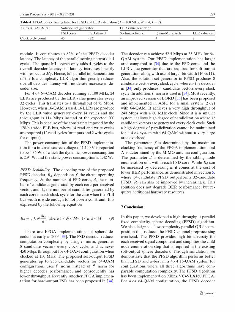
The latency of the PFSD decoder is 55 cycles. Table 4shows the maximum latency required for the individualmodules. Each FSD core takes 45 cycles to generateone candidate vector for a new set of inputs, whichincludes the 22 cycles required by the FSD shared
Table 3 FPGA device utilization summary for PFSD and LLR calculation ( f = 100 MHz, N = 4, k = 2).
module. It contributes to 82% of the PFSD decoderlatency. The latency of the parallel sorting network is 4cycles. The quasi-ML search only adds 4 cycles to theoverall decoder latency; its latency increases linearlywith respect to MT . Hence, full parallel implementationof the low complexity LLR algorithm greatly reducesoverall decoder latency with moderate increase in de-coder size.
For 4×4 64-QAM decoder running at 100 MHz, 24LLRs are produced by the LLR value generator every32 cycles. This translates to a throughput of 75 Mbps.However, when 16-QAM is used, 16 LLRs are produceby the LLR value generator every 14 cycles and thethroughput is 114 Mbps instead of the expected 200Mbps. This is because of the constraints imposed by the128-bit wide PLB bus, where 14 read and write cyclesare required (12 read cycles for inputs and 2 write cyclesfor outputs).
The power consumption of the PFSD implementa-tion for a internal source voltage of 1.140 V is reportedto be 4.36 W, of which the dynamic power consumptionis 2.94 W, and the static power consumption is 1.42 W.
PFSD Scalability The decoding rate of the proposedPFSD decoder, Rd, depends on f , the circuit operatingfrequency, N, the number of FSD cores, d, the num-ber of candidates generated by each core per receivedvector, and, k, the number of candidates generated byeach core in each clock cycle for the case when the PLBbus width is wide enough to not pose a constraint. It isexpressed by the following equation
Rd = f k NMc
d, where 1≤ N ≤ MT , 1≤d, k≤ M (9)
There are FPGA implementations of sphere de-coders as early as 2006 [33]. The FSD decoder reducescomputation complexity by using l1 norm, generates8 candidate vectors every clock cycle, and achieves450 Mbps throughput for 64-QAM configuration whenclocked at 150 MHz. The proposed soft-output PFSDgenerates up to 256 candidate vectors for 64-QAMconfiguration, uses l2 norm instead of l1 norm forhigher decoder performance, and consequently haslower throughput. Recently, another FPGA implemen-tation for hard-output FSD has been proposed in [34].
The decoder can achieve 52.5 Mbps at 35 MHz for 64-QAM system. Our PFSD implementation has largerarea compared to [34] due to the FSD cores and theLLR value generator that are required for soft-outputgeneration, along with use of larger bit width (16 vs 11).Also, the solution set generator in PFSD produces 8candidate vector every clock cycle, whereas the decoderin [34] only produces 4 candidate vectors every clockcycle. In addition, l1 norm is used in [34]. Most recently,an improved version of LORD [35] has been proposedand implemented in ASIC for a small system (2×2)with 64-QAM. It achieves a very high throughput of240 Mbps with a 80 MHz clock. Since it is a smallersystem, it allows high degree of parallelization where 32candidate vectors are generated every clock cycle. Sucha high degree of parallelization cannot be maintainedfor a 4×4 system with 64-QAM without a very largearea overhead.
The parameter f is determined by the maximumclocking frequency of the FPGA implementation, andN is determined by the MIMO antenna configuration.The parameter d is determined by the sibling nodeenumeration unit within each FSD core. While Rd canbe increased by decreasing d, it comes at the cost oflower BER performance, as demonstrated in Section 5,where 64-candidate PFSD outperforms 32-candidatePFSD. Rd can also be improved by increasing k. Thissolution does not degrade BER performance, but re-quires additional hardware resources.
7 Conclusion
In this paper, we developed a high throughput parallelfixed complexity sphere decoding (PFSD) algorithm.We also designed a low complexity parallel QR decom-position that reduces the PFSD channel preprocessingoverhead. The PFSD provides high bit diversity foreach received signal component and simplifies the childnode enumeration step that is required in the existingsoft-output sphere decoders. Through simulation, wedemonstrate that the PFSD algorithm performs betterthan LFSD and k-best in a 4×4 16-QAM system forconfigurations where all three algorithms have com-parable computation complexity. The PFSD algorithmhas been implemented on Xilinx VC4VLX160 FPGA.For 4×4 64-QAM configuration, the PFSD decoder
230 J Sign Process Syst (2012) 68:217–231
can achieve 75Mbps running at 100MHz. The scalabilityof the PFSD decoder is also investigated. Since the datapaths of the PFSD decoder is inherently parallel, it canbe easily mapped onto multiple FPGA chips to achievevery high decoding rate.
References
1. Butler, M. R. G., & Collings, I. B. (2004). A zero-forcing ap-proximate log-likelihood receiver for MIMO bit-interleavedcoded modulation. IEEE Communication Letter, 8, 105–107.
2. Foschini, G. J. (1996). Layered space-time architecture forwireless communication in a fading environment when us-ing multi-element antenna. Bell Labs Technical Journal, 1,41–59.
3. Mobasher, A., Taherzadeh, M., Sotirov, R., & Khandani, A.K. (2005). A near maximum likelihood decoding algorithmfor MIMO systems based on semi-definite programming. InIEEE international symposium on information theory (ISIT)(pp. 1686–1690).
4. Sidiropoulos, N. D., & Luo, Z.-Q. (2006). A semidefiniterelaxation approach to MIMO detection for high-order QAMconstellations. IEEE Signal Processing Letters, 13, 525–528.
5. Pohst, M. (1981). On the computation of lattice vectors ofminimal length, successive minima and reduced bases withapplications. In ACM special interest group on symbolic andalgebraic manipulation (SIGSAM Bull.) (Vol. 15, pp. 37–44).
6. Hassibi, B., & Vikalo, H. (2005). On the sphere-decoding al-gorithm I, expected complexity. IEEE Transactions on SignalProcessing, 53, 2806–2818.
7. Guo, Z., Nilsson, P. (2006). Algorithm and implementation ofthe K-best sphere decoding for MIMO detection. IEEE Trans-actions on Selected Areas in Communications, 44, 491–503.
8. Chen, S., Zhang, T., & Xin, Y. (2007). Relaxed K-bestMIMO signal detector design and VLSI implementation.IEEE Transactions on VLSI Systems, 15, 328–337.
9. Bhagawat, P., Dash, R., & Choi, G. (2009). Systolic like soft-detection architecture for 4 × 4 64-QAM MIMO system. InIEEE The design, automation, and test in Europe (DATE)(pp. 870–873).
10. Barbero, L. G., & Thompson, J. S. (2008). Extending a fixed-complexity sphere decoder to obtain likelihood informationfor Turbo-MIMO systems. IEEE Transactions on VehicularTechnology, 57, 2804–2814.
11. Caire, G., Taricco, G., & Biglieri, E. (1998). Bit-interleavedcoded modulation. IEEE Transaction of Information Theory,8, 927–946.
12. Studer, C., Burg, A., & Bölcskei, H. (2008). Soft-outputsphere decoding: Algorithms and VLSI implementation.IEEE Transactions on Selected Areas in Communications, 26,290–300.
13. Fincke, U., & Pohst, M. (1985). Improved methods for calcu-lating vectors of short length in a lattice, including a complex-ity analysis. Mathematics of Computation, 44, 161–163.
14. Schnorr, C. P., & Euchner, M. (1991). Lattice basis reduction:Improved practical algorithms and solving subset sum prob-lems. Fundamentals of Computation Theory, 529, 68–85.
15. Wong, K. W., Tsui, C. Y., Cheng, R. S.-K., & Mow, W. H.(2002). A VLSI architecture of a K-best lattice decoding algo-rithm for MIMO channels. In IEEE international symposiumon circuits and systems (ISCAS) (Vol. 3, pp. 273–276).
16. Barbero, L. G., & Thompson, J. S. (2006). A fixed-complexityMIMO detector based on the complex sphere decoder. In
IEEE international workshop on signal processing advancesfor wireless communications (SPAWC) (pp. 1–5).
17. Hess, C., Wenk, M., Burg, A., Luethi, P., Studer, C., Felber,N., et al. (2007). Reduced-complexity MIMO detector withclose-to-ML error rate performance. In ACM Great Lakessymposium on VLSI (pp. 200–203).
18. Li, M., Bougard, B., Lopez, E. E., Bourdoux, A., Novo, D.,Van Der Perre, L., et al. (2008). Selective spanning with fastenumeration: A near maximum-likelihood MIMO detectordesigned for parallel programmable baseband architectures.In IEEE international conference on communications (ICC)(pp. 737–741).
19. Milliner, D. L., Zimmermann, E., Barry, J. R., & Fettweis,G. P. (2008). A framework for fixed complexity breadth-first MIMO detection. In IEEE international symposiumon spread spectrum techniques and applications (ISSSTA)(pp. 129–132).
20. Li, M., Novo, D., Bougard, B., Naessens, F., Van der Perre,L., & Catthoor, F. (2008). An implementation friendly lowcomplexity multiplierless LLR generator for soft MIMOsphere decoders. In IEEE workshop on signal processing sys-tems (SiPS) (pp. 118–123).
21. Siti, M., & Fitz, M. P. (2007). On layer ordering techniques fornear-optimal MIMO detectors. In IEEE wireless communica-tions and networking conference (WCNC) (pp. 1199–1204).
22. Siti, M., & Fitz, M. P. (2006). A novel soft-output layeredorthogonal lattice detector for multiple antenna communica-tions. In IEEE international conference on communications(ICC) (pp. 1686–1691).
23. Jalden, J., Barbero, L. G., Ottersten, B., & Thompson, J. S.(2009). The error probability of the fixed-complexity spheredecoder. IEEE Transactions on Signal Processing, 57, 2711–2720.
24. El-Amawy, A., & Dharmarajan, K. R. (1989). Parallel VLSIalgorithm for stable inversion of dense matrices. In Com-puters and digital techniques, IEE proceedings E (Vol. 236,pp. 575–580).
25. Liu, K. R., Hsieh, S.-F., & Yao, K. (1992). Systolic blockhouseholder transformation for RLS algorithm with two-level pipelined implementation. IEEE Transactions on SignalProcessing, 40, 946–958.
26. Wübben, D., Böhnke, R., Rinas, J., Kühn, V., & Kammeyer,K. D. (2001). Efficient algorithm for decoding layered space-time codes. IEEE Transactions on Electronics Letters, 37,1348–1350.
28. Hochwald, B. M., & Brink, S. (2003). Achieving near-capacityon a multiple-antenna channel. IEEE Transactions onCommunications, 51, 389–399.
29. Milliner, D. L., Zimmermann, E., Barry, J. R., & Fettweis,G. (2008). Channel state information based LLR clipping inlist MIMO detection. In IEEE international symposium onpersonal, indoor and mobile radio communications (PIMRC)(pp. 1–5).
30. Burg, A., Borgmann, M., Wenk, M., Zellweger, M., Fichtner,W., & Bolcskei, H. (2005). VLSI implementation of MIMOdetection using the sphere decoding algorithm. IEEE Journalof Solid-State Circuits, 40, 1566–1577.
32. Xilinx. Processor local bus. http://www.xilinx.com/support/documentation/ip_documentation/plb_v46.pdf.
33. Barbero, L. G., & Thompson, J. S. (2006). FPGA design con-siderations in the implementation of a f ixed-throughput spheredecoder for MIMO systems. In IEEE international workshop
on signal processing advances for wireless communications(SPAWC) (pp. 1–5).
34. Bhagawat, P., Dash, R., & Choi, G. (2008). Architecture forreconfigurable MIMO detector and its FPGA implementa-tion. In IEEE international conference on electronics, circuitsand systems (ICECS) (pp. 61–64).
35. Cupaiuolo, T., Siti, M., & Tomasoni, A. (2010). Low-complexity high throughput VLSI architecture of soft-outputML MIMO detector. In Design, automation test in Europeconference exhibition (DATE), 2010 (pp. 1396–1401).
Qi Qi received the B.S., M.S. and Ph.D. degrees in electricalengineering from Arizona State University (ASU), Tempe, in2001, 2004 and 2010, respectively. His research interests includeVLSI architectures and algorithms for communication and signalprocessing systems.
Chaitali Chakrabarti (SM’02) received the B.Tech. degree inelectronics and electrical communication engineering from theIndian Institute of Technology, Kharagpur, India, in 1984, andthe M.S. and Ph.D. degrees in electrical engineering from theUniversity of Maryland, College Park, in 1986 and 1990, re-spectively. She is a Professor with the Department of Electri-cal Engineering, Arizona State University (ASU), Tempe. Herresearch interests include the areas of low power embeddedsystems design including memory optimization, high level synthe-sis and compilation, and VLSI architectures and algorithms forsignal processing, image processing, and communications. Prof.Chakrabarti was a recipient of the Research Initiation Awardfrom the National Science Foundation in 1993, a Best TeacherAward from the College of Engineering and Applied Sciencesfrom ASU in 1994, and the Outstanding Educator Award fromthe IEEE Phoenix Section in 2001. She served as the Techni-cal Committee Chair of the DISPS subcommittee, IEEE SignalProcessing Society (2006-2007). She is now an Associate Editorof the Journal of VLSI Signal Processing Systems and the IEEETransactions on Very Large Scale Integration Systems.


![Sphere Decoding for Noncoherent Channelshcdc/Library/vortrag.pdf · fRefr [k]vr[k 1]gg ( ) r [k 1] r[k] ^v[k] Delay L. Lampe: Sphere Decoding for Noncoherent Channels. Multiple-Symbol](https://static.documents.pub/doc/80x56/60d2b5bf845115239005162c/sphere-decoding-for-noncoherent-hcdclibraryvortragpdf-frefr-kvrk-1gg-.jpg)


