International Journal on “Technical and Physical Problems of Engineering” (IJTPE) Published by International Organization of IOTPE ISSN 2077-3528 IJTPE Journal www.iotpe.com [email protected]March 2014 Issue 18 Volume 6 Number 1 Pages 148-153 148 PARALLEL HYBRID ACTIVE POWER FILTER FOR STATIC REACTIVE POWER AND HARMONICS COMPENSATION WITH SOGI-PLL T. Demirdelen 1 K.C. Bayindir 2 M. Tumay 3 Electrical and Electronics Engineering Department, Cukurova University, Adana, Turkey [email protected], [email protected], [email protected]Abstract- In this paper, according to the lack of relevant studies based on reactive power compensation, the control method related to this subject has been investigated and applied to the Parallel Hybrid Active Power Filter (P-HAPF). Firstly, the dq base control algorithm is applied for harmonic compensation. Then, the reactive power compensation control which is supplied by active filter of hybrid active filter is added. Finally, the static reactive power and harmonic compensation is achieved by P-HAPF. All controllers are written by FORTRAN language in PSCAD/EMTDC. Keywords: Power Quality, Harmonics, Reactive Power, Hybrid Active Filter. I. INTRODUCTION In recent years, with the increase of nonlinear loads in industrial manufacturers, the power quality issue has become more serious. There are various custom power devices to solve these power quality problems. In the past, the passive power filters were often used to solve serious harmonic problems of the grid. Although passive filters were preferred because of its economic and simple structure, new methods are needed due to the disadvantages of passive filter such as requirement of a separate filter for each harmonic current, having limited filtering characteristics, the negative effects caused by parallel and series resonance between grid and filter impedance [1, 2]. The active power filter which is developed to remedy the shortcomings of the passive filter consists of voltage or current source inverter, DC link storage and output filter. When active filter is compared to passive filter, although active filter has complex structure and more costly, today they can solve various power quality problems such as harmonic compensation, reactive power compensation, voltage imbalance, voltage flicker [3, 8, 9]. Even though the active power filter is an effective compensation system, their cost is increasing seriously with the proportion of increasing power capacity [1, 2]. As a solution to this situation, the hybrid active power filters have been developed by using active and passive filters together [3-6]. The main aim in the development of P-HAPF [11, 12] is to reduce the cost and rating of active filter by using passive filter that filters dominant harmonics caused by nonlinear loads and supplies reactive power requirement [2]. In this paper, according to the lack of relevant studies based on reactive power compensation, the control method related to this subject has been investigated and applied to the P-HAPF. Firstly, the dq base control algorithm is applied for harmonic compensation. Then the reactive power compensation control which is supplied by active filter of hybrid active filter is added. Finally, the static reactive power and harmonic compensation is achieved by P-HAPF. All controllers are written by FORTRAN language in PSCAD/EMTDC. II. PARALLEL HYBRID ACTIVE POWER FILTER Parallel hybrid power filter which is the main concern of this article is formed by the use of a three phase voltage source PWM converter, and a series connected LC passive filter directly. Thus, there is no need to use transformer. The series connected LC filter is tuned to dominant harmonic component of the load. It compensates the current harmonics caused of the nonlinear load, however, the filtering characteristic of just the passive filter itself does not give satisfactory results. Hence, active power filter is used to develop the filtering performance of the overall system and to remove the resonance risk of the passive filter. The power circuit of the inverter includes an energy storage element of a DC link capacitor and controllable semiconductor switches with their anti-parallel diodes. Active Power Filter (APF) injects compensation currents by operating as a current controlled voltage source. In conventional voltage source active power filter topology, the DC link capacitor voltage must be greater than the peak value of the grid voltage, else the generated compensation currents cannot be injected to the mains. However, the presence of filter capacitor in this topology ensures a reduced DC link voltage and a low rated voltage source converter at the expense of additional fundamental current, passing through the converter. The P-HAPF topology is illustrated in Figure 1.
Abstract- In this paper, according to the lack of relevant
studies based on reactive power compensation, the
control method related to this subject has been
investigated and applied to the Parallel Hybrid Active
Power Filter (P-HAPF). Firstly, the dq base control
algorithm is applied for harmonic compensation. Then,
the reactive power compensation control which is
supplied by active filter of hybrid active filter is added.
Finally, the static reactive power and harmonic
compensation is achieved by P-HAPF. All controllers are
written by FORTRAN language in PSCAD/EMTDC.
Keywords: Power Quality, Harmonics, Reactive Power,
Hybrid Active Filter.
I. INTRODUCTION
In recent years, with the increase of nonlinear loads in
industrial manufacturers, the power quality issue has
become more serious. There are various custom power
devices to solve these power quality problems. In the
past, the passive power filters were often used to solve
serious harmonic problems of the grid. Although passive
filters were preferred because of its economic and simple
structure, new methods are needed due to the
disadvantages of passive filter such as requirement of a
separate filter for each harmonic current, having limited
filtering characteristics, the negative effects caused by
parallel and series resonance between grid and filter
impedance [1, 2].
The active power filter which is developed to remedy
the shortcomings of the passive filter consists of voltage
or current source inverter, DC link storage and output
filter. When active filter is compared to passive filter,
although active filter has complex structure and more
costly, today they can solve various power quality
problems such as harmonic compensation, reactive power
compensation, voltage imbalance, voltage flicker [3, 8,
9]. Even though the active power filter is an effective
compensation system, their cost is increasing seriously
with the proportion of increasing power capacity [1, 2].
As a solution to this situation, the hybrid active power
filters have been developed by using active and passive
filters together [3-6].
The main aim in the development of P-HAPF [11,
12] is to reduce the cost and rating of active filter by
using passive filter that filters dominant harmonics
caused by nonlinear loads and supplies reactive power
requirement [2].
In this paper, according to the lack of relevant studies
based on reactive power compensation, the control
method related to this subject has been investigated and
applied to the P-HAPF. Firstly, the dq base control
algorithm is applied for harmonic compensation. Then
the reactive power compensation control which is
supplied by active filter of hybrid active filter is added.
Finally, the static reactive power and harmonic
compensation is achieved by P-HAPF. All controllers are
written by FORTRAN language in PSCAD/EMTDC.
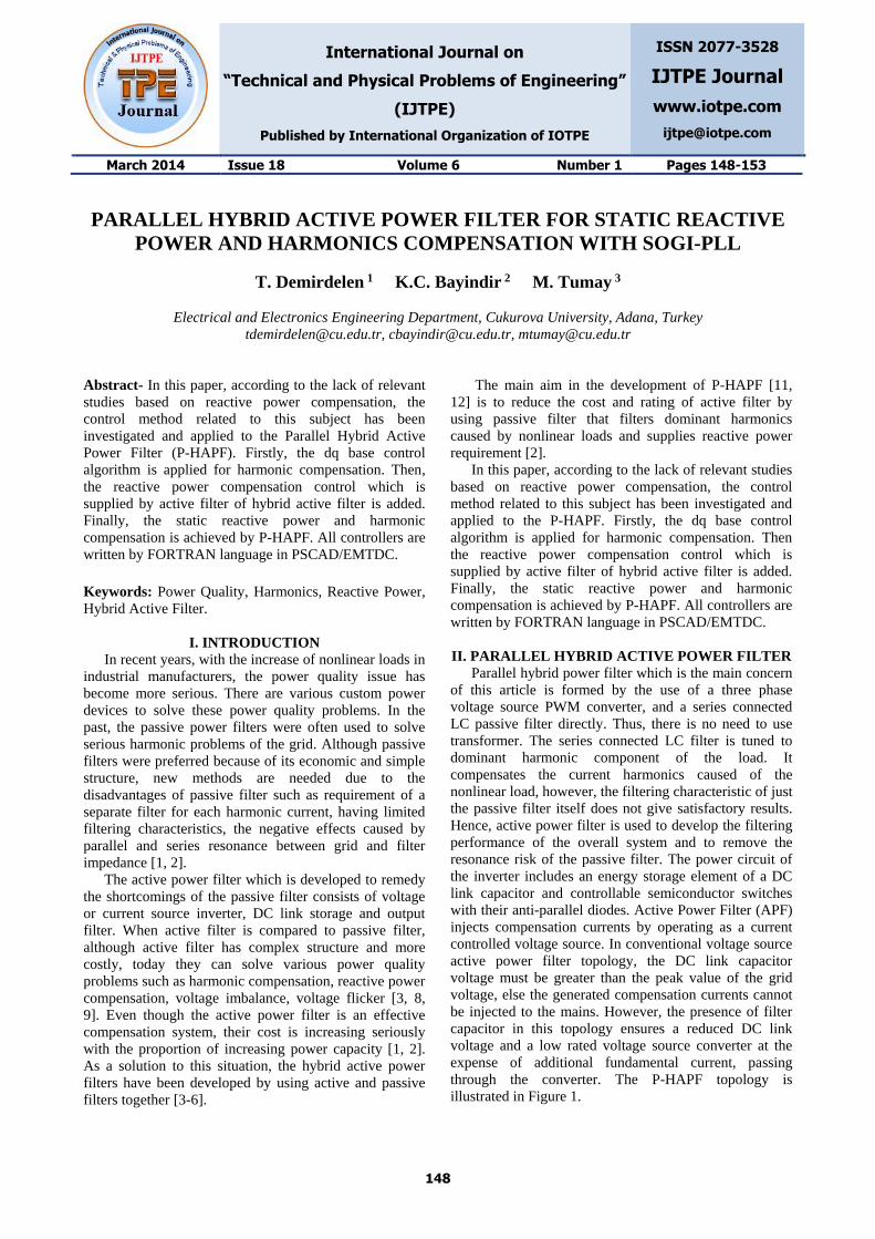
II. PARALLEL HYBRID ACTIVE POWER FILTER
Parallel hybrid power filter which is the main concern
of this article is formed by the use of a three phase
voltage source PWM converter, and a series connected
LC passive filter directly. Thus, there is no need to use
transformer. The series connected LC filter is tuned to
dominant harmonic component of the load. It
compensates the current harmonics caused of the
nonlinear load, however, the filtering characteristic of just
the passive filter itself does not give satisfactory results.
Hence, active power filter is used to develop the filtering
performance of the overall system and to remove the
resonance risk of the passive filter. The power circuit of
the inverter includes an energy storage element of a DC
link capacitor and controllable semiconductor switches
with their anti-parallel diodes. Active Power Filter (APF)
injects compensation currents by operating as a current
controlled voltage source. In conventional voltage source
active power filter topology, the DC link capacitor
voltage must be greater than the peak value of the grid
voltage, else the generated compensation currents cannot
be injected to the mains. However, the presence of filter
capacitor in this topology ensures a reduced DC link
voltage and a low rated voltage source converter at the
expense of additional fundamental current, passing
through the converter. The P-HAPF topology is
illustrated in Figure 1.
International Journal on “Technical and Physical Problems of Engineering” (IJTPE), Iss. 18, Vol. 6, No. 1, Mar. 2014
149
As a result, for low voltage applications, PWM
converter can be formed by power MOSFETs instead of
using IGBTs. So that, the initial cost of the converter can
be decreased by using MOSFETs instead of IGBTs.
Similar to conventional VSC based APFs, P-HAPF does
not require a DC power supply for its DC link voltage
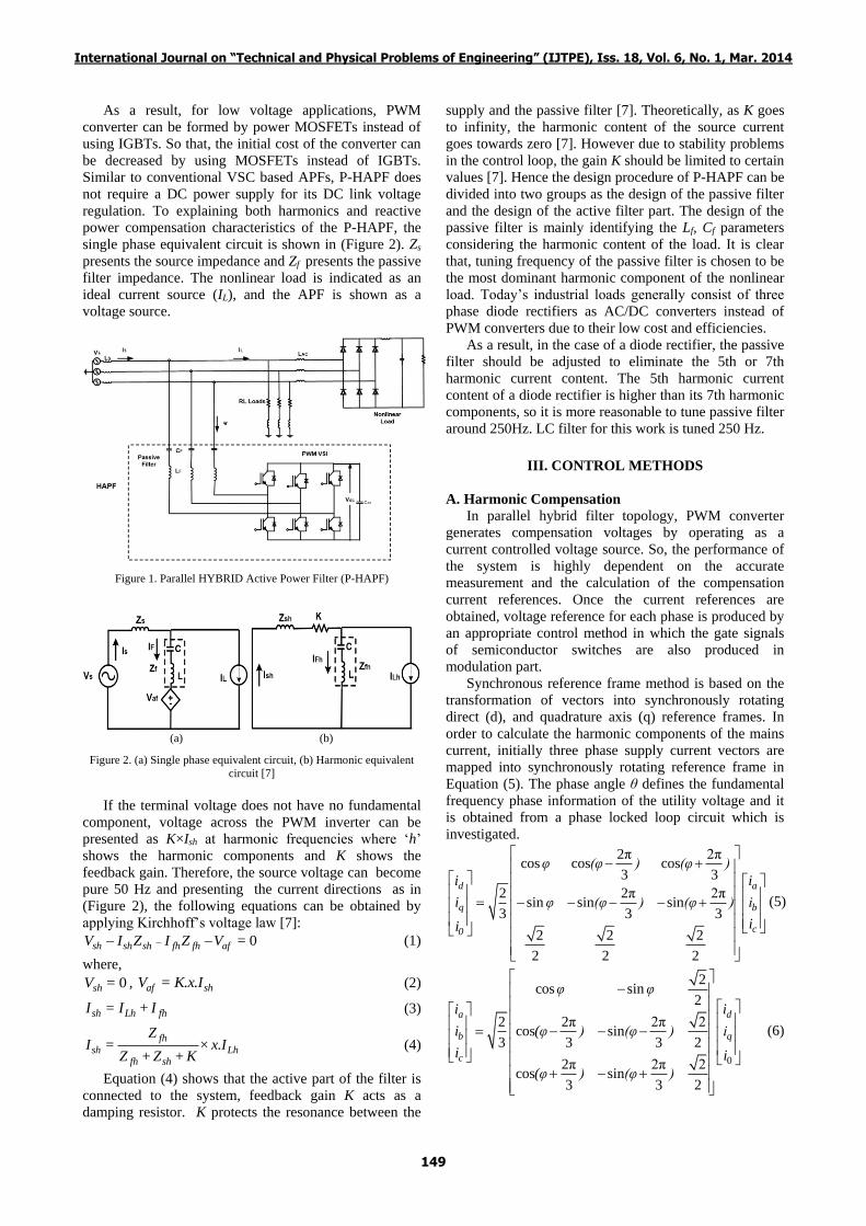
regulation. To explaining both harmonics and reactive
power compensation characteristics of the P-HAPF, the
single phase equivalent circuit is shown in (Figure 2). Zs
presents the source impedance and Zf presents the passive
filter impedance. The nonlinear load is indicated as an
ideal current source (IL), and the APF is shown as a
voltage source.
Figure 1. Parallel HYBRID Active Power Filter (P-HAPF)
(a) (b)
Figure 2. (a) Single phase equivalent circuit, (b) Harmonic equivalent
circuit [7]
If the terminal voltage does not have no fundamental
component, voltage across the PWM inverter can be
presented as K×Ish at harmonic frequencies where ‘h’
shows the harmonic components and K shows the
feedback gain. Therefore, the source voltage can become
pure 50 Hz and presenting the current directions as in
(Figure 2), the following equations can be obtained by
applying Kirchhoff’s voltage law [7]:
0sh sh sh fh fh afV I Z I Z V = (1)
where,
0shV = , af shV = K.x.I (2)
sh Lh fhI = I + I (3)
fh
sh Lhfh sh
ZI = × x.I
Z +Z + K (4)
Equation (4) shows that the active part of the filter is
connected to the system, feedback gain K acts as a
damping resistor. K protects the resonance between the
supply and the passive filter [7]. Theoretically, as K goes
to infinity, the harmonic content of the source current
goes towards zero [7]. However due to stability problems
in the control loop, the gain K should be limited to certain
values [7]. Hence the design procedure of P-HAPF can be
divided into two groups as the design of the passive filter
and the design of the active filter part. The design of the
passive filter is mainly identifying the Lf, Cf parameters
considering the harmonic content of the load. It is clear
that, tuning frequency of the passive filter is chosen to be
the most dominant harmonic component of the nonlinear
load. Today’s industrial loads generally consist of three
phase diode rectifiers as AC/DC converters instead of
PWM converters due to their low cost and efficiencies.
As a result, in the case of a diode rectifier, the passive
filter should be adjusted to eliminate the 5th or 7th
harmonic current content. The 5th harmonic current
content of a diode rectifier is higher than its 7th harmonic
components, so it is more reasonable to tune passive filter
around 250Hz. LC filter for this work is tuned 250 Hz.
III. CONTROL METHODS
A. Harmonic Compensation
In parallel hybrid filter topology, PWM converter
generates compensation voltages by operating as a
current controlled voltage source. So, the performance of
the system is highly dependent on the accurate
measurement and the calculation of the compensation
current references. Once the current references are
obtained, voltage reference for each phase is produced by
an appropriate control method in which the gate signals
of semiconductor switches are also produced in
modulation part.
Synchronous reference frame method is based on the
transformation of vectors into synchronously rotating
direct (d), and quadrature axis (q) reference frames. In
order to calculate the harmonic components of the mains
current, initially three phase supply current vectors are
mapped into synchronously rotating reference frame in
Equation (5). The phase angle θ defines the fundamental
frequency phase information of the utility voltage and it
is obtained from a phase locked loop circuit which is
investigated.
2π 2πcos cos cos
3 3
2 2π 2πsin sin sin
3 3 3
2 2 2
2 2 2
d a
q b
c0
φ (φ ) (φ )
i i
i φ (φ ) (φ ) i
ii
(5)
0
2cos sin
2
2 2π 2π 2cos sin
3 3 3 2
2π 2π 2cos sin
3 3 2
a d
b q
c
φ φ
i i
i (φ ) (φ ) i
i i
(φ ) (φ )
(6)
International Journal on “Technical and Physical Problems of Engineering” (IJTPE), Iss. 18, Vol. 6, No. 1, Mar. 2014
150
Once the current vectors are transformed into
synchronously rotating dq reference frame, the
fundamental component of the mains current converts to
be a DC signal, and the harmonic components which are
still AC signals are rotating with a corresponding angular
frequency.
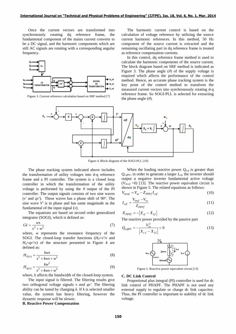
Figure 3. Current reference calculation based on SRF method [7]
The harmonic current control is based on the
calculation of voltage reference by utilizing the source
current harmonic references. In this method, 50 Hz
component of the source current is extracted and the
remaining oscillating part in dq reference frame is treated
as reference compensation currents.
In this control, dq reference frame method is used to
calculate the harmonic components of the source current.
The block diagram based on SRF method is indicated as
Figure 3. The phase angle (θ) of the supply voltage is
required which affects the performance of the control
method. Hence, an accurate phase tracking system is the
key point of the control method to transform the
measured current vectors into synchronously rotating d-q
reference frame. So SOGI-PLL is selected for extracting
the phase angle (θ).
Figure 4. Block diagram of the SOGI-PLL [10]
The phase tracking system indicated above includes
the transformation of utility voltages into d-q reference
frame and a PI controller. The system is a closed loop
controller in which the transformation of the utility
voltage is performed by using the θ output of the PI
controller. The output signals consists of two sine waves
(v' and qv'). These waves has a phase shift of 90°. The
sine wave V' is in phase and has same magnitude as the
fundamental of the input signal (v).
The equations are based on second order generalized
integrator (SOGI), which is defined as:
2 2
wsGI
s w
(7)
where, w represents the resonance frequency of the
SOGI. The closed-loop transfer functions (Hd=v'/v and
Hq=qv'/v) of the structure presented in Figure 4 are
defined as:
( ) 2 2d s
kwsH
s kws w
(8)
2
( ) 2 2q s
kwH
s kws w
(9)
where, k affects the bandwidth of the closed-loop system.
The input signal is filtered. The filtering results give
two orthogonal voltage signals v and qv'. The filtering
ability can be tuned by changing k. If k is selected smaller
value, the system has heavy filtering, however the
dynamic response will be slower.
B. Reactive Power Compensation
When the loading reactive power QLxf is greater than QcxfPF, in order to generate a larger Icxf, the inverter should output a negative inverter fundamental active voltage (Vinvxf <0) [13]. The reactive power equivalent circuit is shown in Figure 5. The related equations as follows:
invxf sx PPFf cxfV V Z I (10)
inxf sx
cxfPPFf
V VI
Z
(11)
PPFf cf LfX X X (12)
The reactive power provided by the passive part 2
0sxcxfPF
c f Lf
VQ
X X
(13)
Figure 5. Reactive power equivalent circuit [13]
C. DC Link Control
Proportional plus integral (PI) controller is used for dc link control of PHAPF. The PHAPF is not used any external supply to regulate or charge dc link capacitor. Thus, the PI controller is important to stability of dc link voltage.
International Journal on “Technical and Physical Problems of Engineering” (IJTPE), Iss. 18, Vol. 6, No. 1, Mar. 2014
151
The dc link voltage amount directly effects to reactive
power and harmonics compensation ability of P-HAPF.
For only harmonic compensation, the dc link voltage
value is decreased compared to both reactive power
compensation and harmonics compensation.
The current reference (∆Iq1) obtained in this control
loop is added to the dc link control signal Vdc-pi. The dc
link control block diagram is presented in Figure 6.
D. Proposed Control Block
The proposed control block consists of four parts
which represents as Figure 6:
a. Determination of harmonic reference current
b. Determination of reference reactive power current
c. DC link voltage control
d. Voltage reference PWM control
Figure 6. Proposed control block diagram of P-HAPF
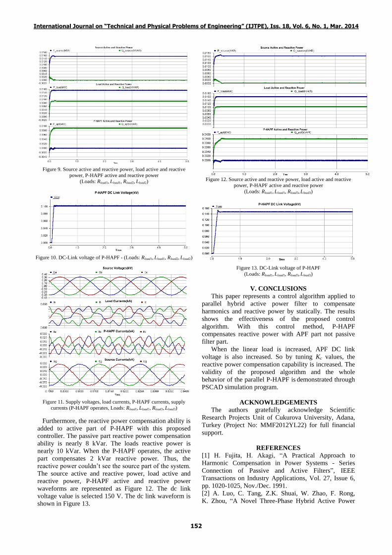
IV. SIMULATION AND RESULTS
In this work, simulation model of the system is
formed by using EMTDC/PSCAD 4.2.0 Professional
software. The Parallel Hybrid Active Power Filter is
modeled, simulated and analyzed in PSCAD 4.2.0
environment. The control methods are developed in
FORTRAN language. The simulation power system is
shown in Figure 1. Table 1 shows simulation parameters.
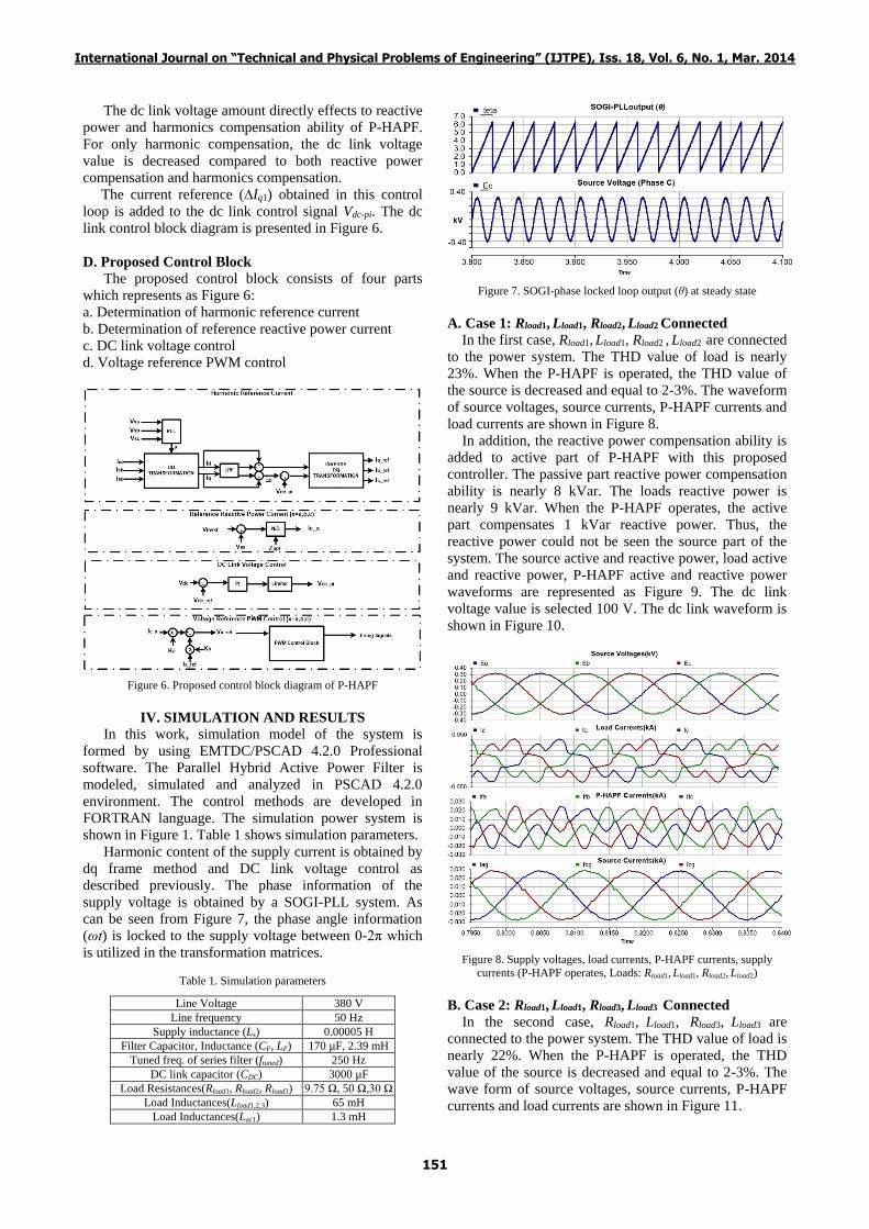
Harmonic content of the supply current is obtained by
dq frame method and DC link voltage control as
described previously. The phase information of the
supply voltage is obtained by a SOGI-PLL system. As
can be seen from Figure 7, the phase angle information
(ωt) is locked to the supply voltage between 0-2π which