18
1 ME 759: Project Report Parallel Implementation of VLSI Gate Placement in CUDA Movers and Placers Kai Zhao Snehal Mhatre December 21, 2015
1
ME 759: Project Report
Parallel Implementation of VLSI Gate
Placement in CUDA
Movers and Placers
Kai Zhao
Snehal Mhatre
December 21, 2015
2
Table of Contents
1. Introduction………………………………………...………………………………………... 3
2. Problem Formulation………………………………………...……………………………… 4
3. Methods and Procedure………………………………….………………………….………. 5
3.1 CPU Implementation…………………………………………………………………... 8
3.2 GPU1 Implementation…………………………………………………………………. 9
3.3 GPU2 Implementation…………………………………………………………………10
3.4 GPU3 Implementation…………………………………………………………………12
3.5 GPU4 Implementation…………………………………………………………………14
4. Simulation Results….…………………………………………………………………….....15
5. Conclusion………………………………………………………………………………..…17
6. References………………………………………………………………………………..….18
3
Abstract: It is critical that Electronic Design Automation algorithms explore the possibilities of
using GPU computing for extensive time consuming applications. This paper focuses on
implementing gate placement algorithms for obtaining optimal wire length using CUDA and
comparing it with a CPU implementation. GPU is approximately 3900 times faster than CPU for
a similar algorithm for larger benchmarks. Optimizing GPU implementation further by hiding
memory access latency and using shared memory is approximately 6400 times faster than CPU.
This paper lays a foundation for doing gate placement on GPU kernel, and provides a game
changing paradigm in VLSI EDA.
1. INTRODUCTION
A modern Very-Large Scale Integration (VLSI) chip is extraordinarily complex with billions of
transistors, millions of logic blocks, big blocks of memory, and routing to connect them all
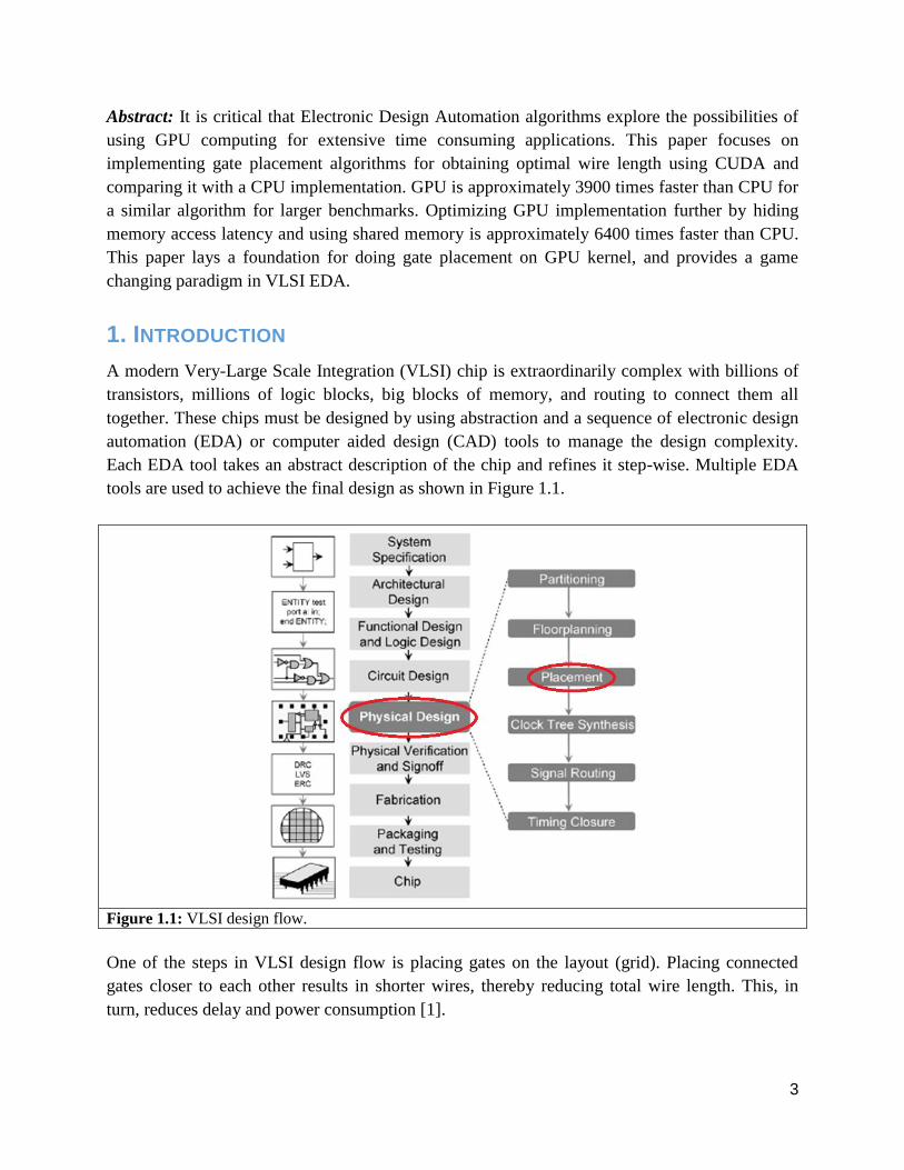
together. These chips must be designed by using abstraction and a sequence of electronic design
automation (EDA) or computer aided design (CAD) tools to manage the design complexity.
Each EDA tool takes an abstract description of the chip and refines it step-wise. Multiple EDA
tools are used to achieve the final design as shown in Figure 1.1.
Figure 1.1: VLSI design flow.
One of the steps in VLSI design flow is placing gates on the layout (grid). Placing connected
gates closer to each other results in shorter wires, thereby reducing total wire length. This, in
turn, reduces delay and power consumption [1].
4
Many of the problems that arise in EDA for VLSI, are NP-complete that require an exponentially
expensive amount of time. The trends of EDA often require either heuristic solutions or
partitioning into smaller tractable problems. Graphics Processing Units (GPUs) are being
extensively used because of their high performance capabilities, especially in extensive time
consuming, large data applications. Therefore, VLSI can greatly benefit from high parallelization
of GPU computing [3]. This paper focusses on a case study of gate placement on GPU.
2. PROBLEM FORMULATION
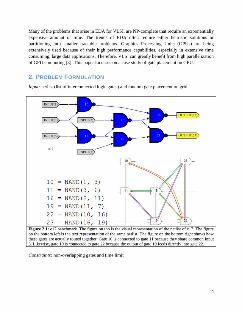
Input: netlist (list of interconnected logic gates) and random gate placement on grid
Figure 2.1: c17 benchmark. The figure on top is the visual representation of the netlist of c17. The figure
on the bottom left is the text representation of the same netlist. The figure on the bottom right shows how
these gates are actually routed together. Gate 10 is connected to gate 11 because they share common input
3. Likewise, gate 10 is connected to gate 22 because the output of gate 10 feeds directly into gate 22.
Constraints: non-overlapping gates and time limit
5
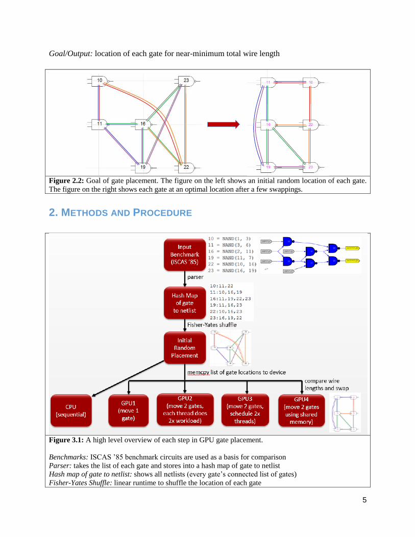
Goal/Output: location of each gate for near-minimum total wire length
Figure 2.2: Goal of gate placement. The figure on the left shows an initial random location of each gate.
The figure on the right shows each gate at an optimal location after a few swappings.
2. METHODS AND PROCEDURE
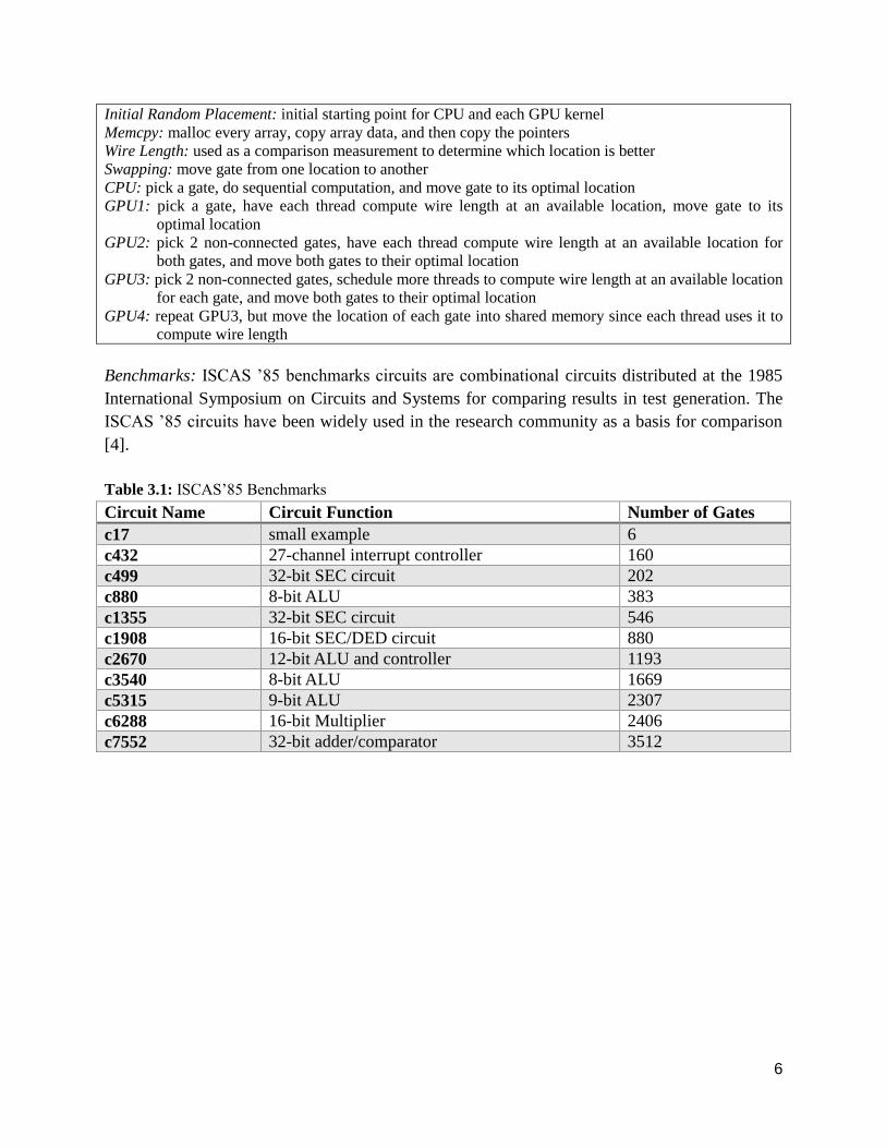
Figure 3.1: A high level overview of each step in GPU gate placement.
Benchmarks: ISCAS ’85 benchmark circuits are used as a basis for comparison
Parser: takes the list of each gate and stores into a hash map of gate to netlist
Hash map of gate to netlist: shows all netlists (every gate’s connected list of gates)
Fisher-Yates Shuffle: linear runtime to shuffle the location of each gate
6
Initial Random Placement: initial starting point for CPU and each GPU kernel
Memcpy: malloc every array, copy array data, and then copy the pointers
Wire Length: used as a comparison measurement to determine which location is better
Swapping: move gate from one location to another
CPU: pick a gate, do sequential computation, and move gate to its optimal location
GPU1: pick a gate, have each thread compute wire length at an available location, move gate to its
optimal location
GPU2: pick 2 non-connected gates, have each thread compute wire length at an available location for
both gates, and move both gates to their optimal location
GPU3: pick 2 non-connected gates, schedule more threads to compute wire length at an available location
for each gate, and move both gates to their optimal location
GPU4: repeat GPU3, but move the location of each gate into shared memory since each thread uses it to
compute wire length
Benchmarks: ISCAS ’85 benchmarks circuits are combinational circuits distributed at the 1985
International Symposium on Circuits and Systems for comparing results in test generation. The
ISCAS ’85 circuits have been widely used in the research community as a basis for comparison
[4].
Table 3.1: ISCAS’85 Benchmarks
Circuit Name Circuit Function Number of Gates
c17 small example 6
c432 27-channel interrupt controller 160
c499 32-bit SEC circuit 202
c880 8-bit ALU 383
c1355 32-bit SEC circuit 546
c1908 16-bit SEC/DED circuit 880
c2670 12-bit ALU and controller 1193
c3540 8-bit ALU 1669
c5315 9-bit ALU 2307
c6288 16-bit Multiplier 2406
c7552 32-bit adder/comparator 3512
7
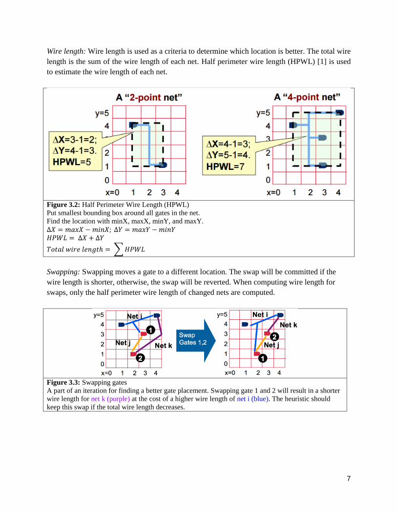
Wire length: Wire length is used as a criteria to determine which location is better. The total wire
length is the sum of the wire length of each net. Half perimeter wire length (HPWL) [1] is used
to estimate the wire length of each net.
Figure 3.2: Half Perimeter Wire Length (HPWL)
Put smallest bounding box around all gates in the net.
Find the location with minX, maxX, minY, and maxY.
∆𝑋 = 𝑚𝑎𝑥𝑋 − 𝑚𝑖𝑛𝑋; ∆𝑌 = 𝑚𝑎𝑥𝑌 − 𝑚𝑖𝑛𝑌
𝐻𝑃𝑊𝐿 = ∆𝑋 + ∆𝑌
𝑇𝑜𝑡𝑎𝑙 𝑤𝑖𝑟𝑒 𝑙𝑒𝑛𝑔𝑡ℎ = ∑ 𝐻𝑃𝑊𝐿
Swapping: Swapping moves a gate to a different location. The swap will be committed if the
wire length is shorter, otherwise, the swap will be reverted. When computing wire length for
swaps, only the half perimeter wire length of changed nets are computed.
Figure 3.3: Swapping gates
A part of an iteration for finding a better gate placement. Swapping gate 1 and 2 will result in a shorter
wire length for net k (purple) at the cost of a higher wire length of net i (blue). The heuristic should
keep this swap if the total wire length decreases.
8
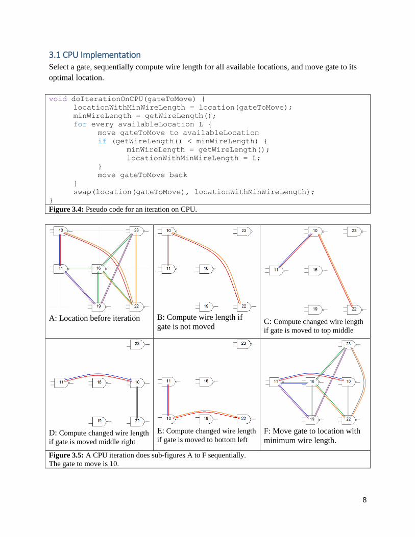
3.1 CPU Implementation Select a gate, sequentially compute wire length for all available locations, and move gate to its
optimal location.
void doIterationOnCPU(gateToMove) {
locationWithMinWireLength = location(gateToMove);
minWireLength = getWireLength();
for every availableLocation L {
move gateToMove to availableLocation
if (getWireLength() < minWireLength) {
minWireLength = getWireLength();
locationWithMinWireLength = L;
}
move gateToMove back
}
swap(location(gateToMove), locationWithMinWireLength);
}
Figure 3.4: Pseudo code for an iteration on CPU.
A: Location before iteration B: Compute wire length if
gate is not moved C: Compute changed wire length
if gate is moved to top middle
D: Compute changed wire length
if gate is moved middle right
E: Compute changed wire length
if gate is moved to bottom left
F: Move gate to location with
minimum wire length.
Figure 3.5: A CPU iteration does sub-figures A to F sequentially.
The gate to move is 10.
9
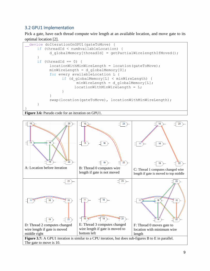
3.2 GPU1 Implementation Pick a gate, have each thread compute wire length at an available location, and move gate to its
optimal location [2].
__device doIterationOnGPU1(gateToMove) {
if (threadId < numAvailableLocation) {
d_globalMemory[threadId] = getPartialWirelengthIfMoved();
}
if (threadId == 0) {
locationWithMinWireLength = location(gateToMove);
minWireLength = d_globalMemory[0];
for every availableLocation L {
if (d_globalMemory[L] < minWireLength) {
minWireLength = d_globalMemory[L];
locationWithMinWireLength = L;
}
}
swap(location(gateToMove), locationWithMinWireLength);
}
} Figure 3.6: Pseudo code for an iteration on GPU1.
A: Location before iteration B: Thread 0 computes wire
length if gate is not moved C: Thread 1 computes changed wire
length if gate is moved to top middle
D: Thread 2 computes changed
wire length if gate is moved
middle right
E: Thread 3 computes changed
wire length if gate is moved to
bottom left
F: Thread 0 moves gate to
location with minimum wire
length
Figure 3.7: A GPU1 iteration is similar to a CPU iteration, but does sub-figures B to E in parallel.
The gate to move is 10.
10
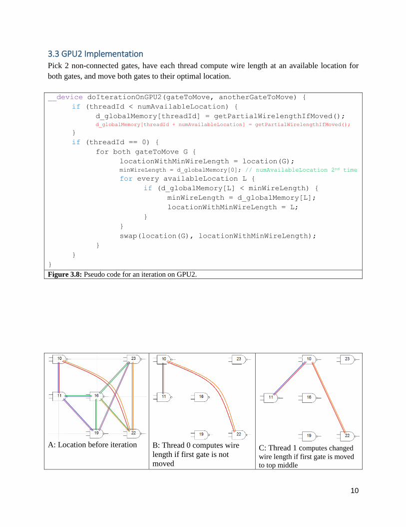
3.3 GPU2 Implementation Pick 2 non-connected gates, have each thread compute wire length at an available location for
both gates, and move both gates to their optimal location.
__device doIterationOnGPU2(gateToMove, anotherGateToMove) {
if (threadId < numAvailableLocation) {
d_globalMemory[threadId] = getPartialWirelengthIfMoved();
d_globalMemory[threadId + numAvailableLocation] = getPartialWirelengthIfMoved();
}
if (threadId == 0) {
for both gateToMove G {
locationWithMinWireLength = location(G);
minWireLength = d_globalMemory[0]; // numAvailableLocation 2nd time
for every availableLocation L {
if (d_globalMemory[L] < minWireLength) {
minWireLength = d_globalMemory[L];
locationWithMinWireLength = L;
}
}
swap(location(G), locationWithMinWireLength);
}
}
}
Figure 3.8: Pseudo code for an iteration on GPU2.
A: Location before iteration B: Thread 0 computes wire
length if first gate is not
moved
C: Thread 1 computes changed
wire length if first gate is moved
to top middle
11
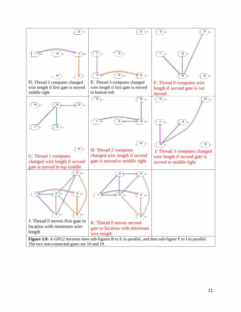
D: Thread 2 computes changed
wire length if first gate is moved
middle right
E: Thread 3 computes changed
wire length if first gate is moved
to bottom left
F: Thread 0 computes wire
length if second gate is not
moved
G: Thread 1 computes
changed wire length if second
gate is moved to top middle
H: Thread 2 computes
changed wire length if second
gate is moved to middle right
I: Thread 3 computes changed
wire length if second gate is
moved to middle right
J: Thread 0 moves first gate to
location with minimum wire
length
K: Thread 0 moves second
gate to location with minimum
wire length
Figure 3.9: A GPU2 iteration does sub-figures B to E in parallel, and then sub-figure F to I in parallel.
The two non-connected gates are 10 and 19.
12
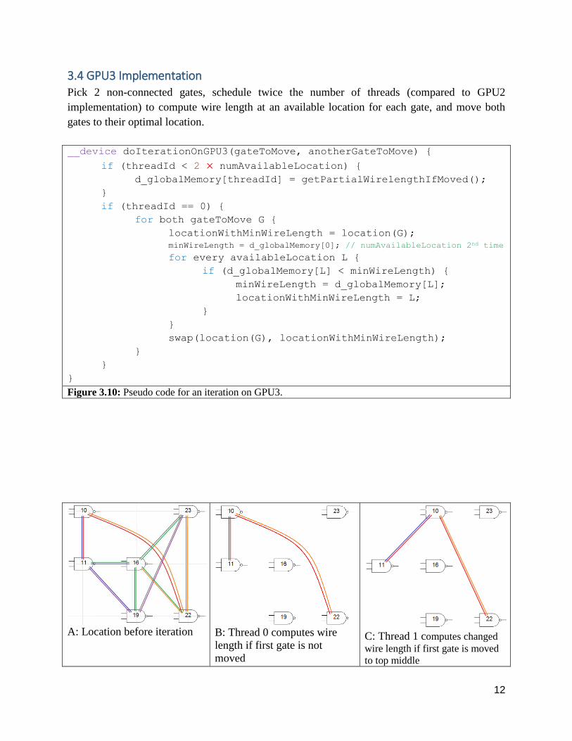
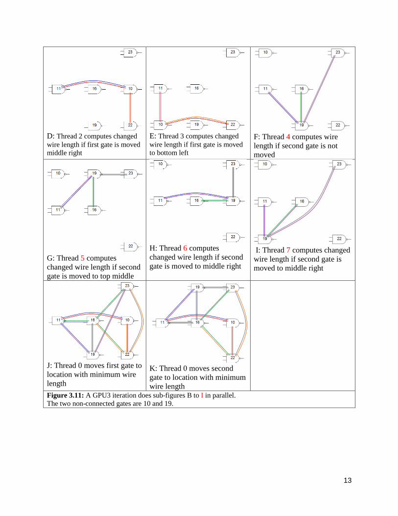
3.4 GPU3 Implementation Pick 2 non-connected gates, schedule twice the number of threads (compared to GPU2
implementation) to compute wire length at an available location for each gate, and move both
gates to their optimal location.
__device doIterationOnGPU3(gateToMove, anotherGateToMove) {
if (threadId < 2 × numAvailableLocation) {
d_globalMemory[threadId] = getPartialWirelengthIfMoved();
}
if (threadId == 0) {
for both gateToMove G {
locationWithMinWireLength = location(G);
minWireLength = d_globalMemory[0]; // numAvailableLocation 2nd time
for every availableLocation L {
if (d_globalMemory[L] < minWireLength) {
minWireLength = d_globalMemory[L];
locationWithMinWireLength = L;
}
}
swap(location(G), locationWithMinWireLength);
}
}
}
Figure 3.10: Pseudo code for an iteration on GPU3.
A: Location before iteration B: Thread 0 computes wire
length if first gate is not
moved
C: Thread 1 computes changed
wire length if first gate is moved
to top middle
13
D: Thread 2 computes changed
wire length if first gate is moved
middle right
E: Thread 3 computes changed
wire length if first gate is moved
to bottom left
F: Thread 4 computes wire
length if second gate is not
moved
G: Thread 5 computes
changed wire length if second
gate is moved to top middle
H: Thread 6 computes
changed wire length if second
gate is moved to middle right
I: Thread 7 computes changed
wire length if second gate is
moved to middle right
J: Thread 0 moves first gate to
location with minimum wire
length
K: Thread 0 moves second
gate to location with minimum
wire length
Figure 3.11: A GPU3 iteration does sub-figures B to I in parallel.
The two non-connected gates are 10 and 19.
14
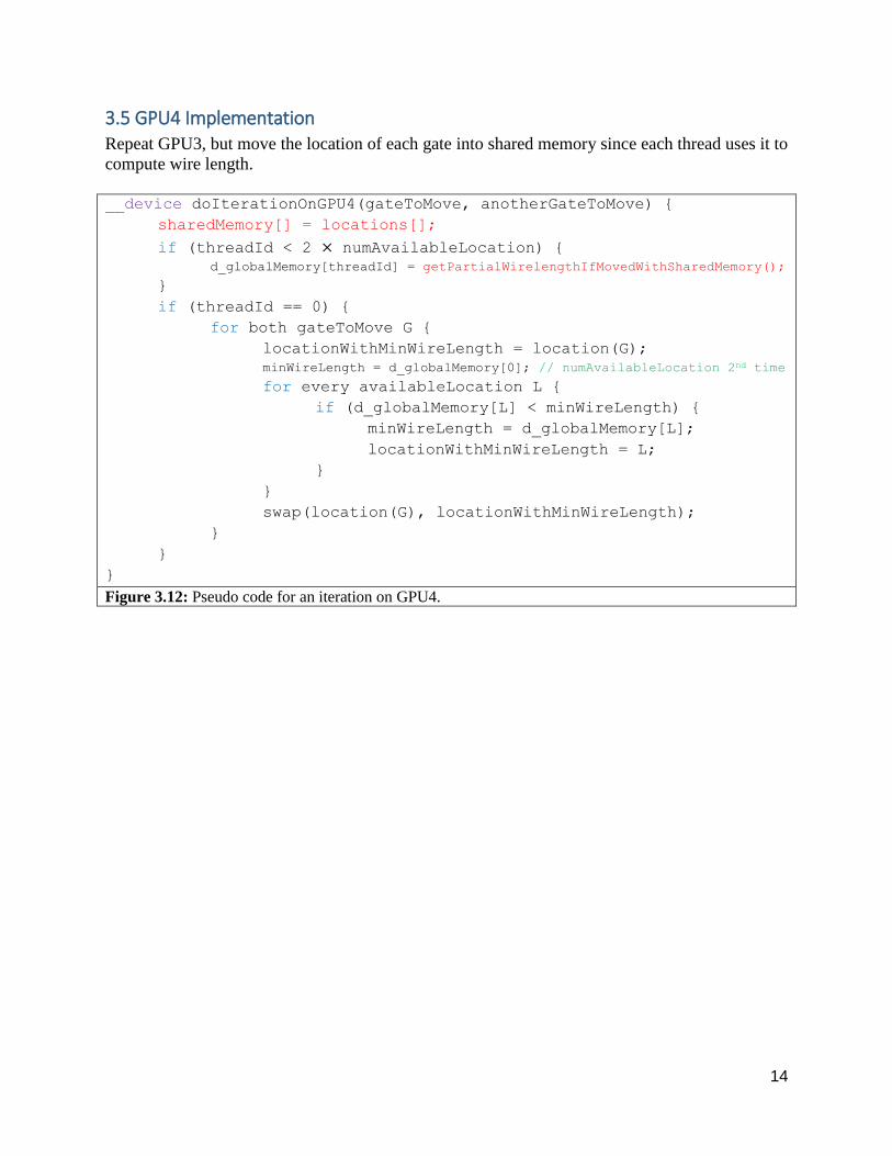
3.5 GPU4 Implementation Repeat GPU3, but move the location of each gate into shared memory since each thread uses it to
compute wire length.
__device doIterationOnGPU4(gateToMove, anotherGateToMove) {
sharedMemory[] = locations[];
if (threadId < 2 × numAvailableLocation) { d_globalMemory[threadId] = getPartialWirelengthIfMovedWithSharedMemory();
}
if (threadId == 0) {
for both gateToMove G {
locationWithMinWireLength = location(G);
minWireLength = d_globalMemory[0]; // numAvailableLocation 2nd time
for every availableLocation L {
if (d_globalMemory[L] < minWireLength) {
minWireLength = d_globalMemory[L];
locationWithMinWireLength = L;
}
}
swap(location(G), locationWithMinWireLength);
}
}
}
Figure 3.12: Pseudo code for an iteration on GPU4.
15
4. SIMULATION RESULTS
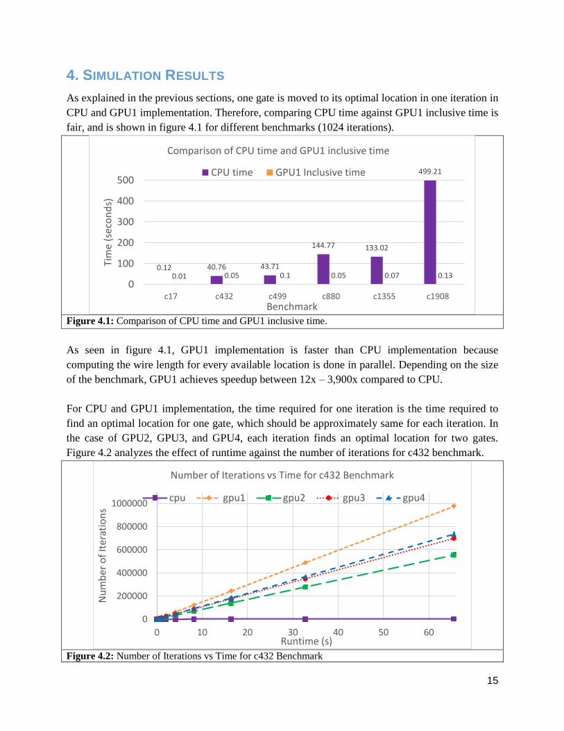
As explained in the previous sections, one gate is moved to its optimal location in one iteration in
CPU and GPU1 implementation. Therefore, comparing CPU time against GPU1 inclusive time is
fair, and is shown in figure 4.1 for different benchmarks (1024 iterations).
Figure 4.1: Comparison of CPU time and GPU1 inclusive time.
As seen in figure 4.1, GPU1 implementation is faster than CPU implementation because
computing the wire length for every available location is done in parallel. Depending on the size
of the benchmark, GPU1 achieves speedup between 12x – 3,900x compared to CPU.
For CPU and GPU1 implementation, the time required for one iteration is the time required to
find an optimal location for one gate, which should be approximately same for each iteration. In
the case of GPU2, GPU3, and GPU4, each iteration finds an optimal location for two gates.
Figure 4.2 analyzes the effect of runtime against the number of iterations for c432 benchmark.
Figure 4.2: Number of Iterations vs Time for c432 Benchmark
0.12 40.76 43.71
144.77 133.02
499.21
0.01 0.05 0.1 0.05 0.07 0.130
100
200
300
400
500
c17 c432 c499 c880 c1355 c1908
Tim
e (
seco
nd
s)
Benchmark
Comparison of CPU time and GPU1 inclusive time
CPU time GPU1 Inclusive time
0
200000
400000
600000
800000
1000000
0 10 20 30 40 50 60
Nu
mb
er o
f It
erat
ion
s
Runtime (s)
Number of Iterations vs Time for c432 Benchmark
cpu gpu1 gpu2 gpu3 gpu4
16
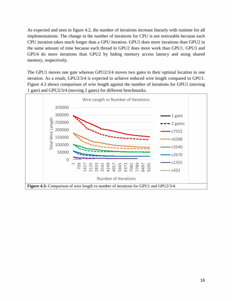
As expected and seen in figure 4.2, the number of iterations increase linearly with runtime for all
implementations. The change in the number of iterations for CPU is not noticeable because each
CPU iteration takes much longer than a GPU iteration. GPU1 does more iterations than GPU2 in
the same amount of time because each thread in GPU2 does more work than GPU1. GPU3 and
GPU4 do more iterations than GPU2 by hiding memory access latency and using shared
memory, respectively.
The GPU1 moves one gate whereas GPU2/3/4 moves two gates to their optimal location in one
iteration. As a result, GPU2/3/4 is expected to achieve reduced wire length compared to GPU1.
Figure 4.3 shows comparison of wire length against the number of iterations for GPU1 (moving
1 gate) and GPU2/3/4 (moving 2 gates) for different benchmarks.
Figure 4.3: Comparison of wire length vs number of iterations for GPU1 and GPU2/3/4.
0
50000
100000
150000
200000
250000
300000
350000
1
70
9
14
17
21
25
28
33
35
41
42
49
49
57
56
65
63
73
70
81
77
89
84
97
92
05
Tota
l Wir
e Le
ngt
h
Number of Iterations
Wire Length vs Number of Iterations
1 gate
2 gates
c7552
c6288
c3540
c2670
c1355
c432
17
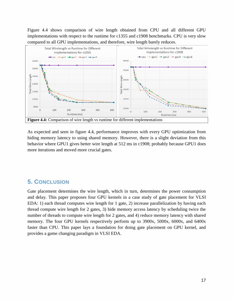
Figure 4.4 shows comparison of wire length obtained from CPU and all different GPU
implementations with respect to the runtime for c1355 and c1908 benchmarks. CPU is very slow
compared to all GPU implementations, and therefore, wire length barely reduces.
Figure 4.4: Comparison of wire length vs runtime for different implementations
As expected and seen in figure 4.4, performance improves with every GPU optimization from
hiding memory latency to using shared memory. However, there is a slight deviation from this
behavior where GPU1 gives better wire length at 512 ms in c1908; probably because GPU1 does
more iterations and moved more crucial gates.
5. CONCLUSION
Gate placement determines the wire length, which in turn, determines the power consumption
and delay. This paper proposes four GPU kernels in a case study of gate placement for VLSI
EDA: 1) each thread computes wire length for 1 gate, 2) increase parallelization by having each
thread compute wire length for 2 gates, 3) hide memory access latency by scheduling twice the
number of threads to compute wire length for 2 gates, and 4) reduce memory latency with shared
memory. The four GPU kernels respectively perform up to 3900x, 5000x, 6000x, and 6400x
faster than CPU. This paper lays a foundation for doing gate placement on GPU kernel, and
provides a game changing paradigm in VLSI EDA.
18
6. REFERENCES
[1] R. Rutenbar, "ASIC Placement," https://spark-public.s3.amazonaws.com/vlsicad/lecture_slides/9-
vlsicad-placer.pdf, University of Illinois, 2013.
[2] A. Al-Kawam, H. Harmanani, "A Parallel GPU Implementation of the TimberWolf Placement
Algorithm," In Information Technology - New Generations (ITNG), 2015 12th International
Conference on, vol., no., pages 792-795, 13-15 April 2015.
[3] G. Flach, M. Johann, R. Hentschke, and R. Reis, "Cell placement on graphics processing units," In
SBCCI ’07: Proc. Annual Conference on Integrated Circuits and Systems Design, pages 87–92, 2007.
[4] M. Hansen, H. Yalcin, J. Hayes, “ISCAS High-Level Models,”
http://web.eecs.umich.edu/~jhayes/iscas.restore/benchmark.html, University of Michigan, 1999.


