Parallel Logic Simulation of VLSI Systems MARY L. BAILEY Department of Computer Science, University of Arizona, Tucson, Arizona 85721 JACK V. BRINER, JR. Department of Mathematics, The University of North Carolina at Greensboro, Greensboro, North Carolina 27412 ROGER D. CHAMBERLAIN Department of Electr~cal Engineering, Washington Uniuers~ty, St. Louis, Missouri 63130 Fast, efficient logic simulators are an essential tool in modern VLSI system design. Logic simulation is used extensively for design verification prior to fabrication, and as VLSI systems grow in size, the execution time required by simulation is becoming more and more significant. Faster logic simulators will have an appreciable economic impact, speeding time to market while ensuring more thorough system design testing. One approach to this problem is to utilize parallel processing, taking advantage of the concurrency available in the VLSI system to accelerate the logic simulation task. Parallel logic simulation has received a great deal of attention over the past several years, but this work has not yet resulted in effective, high-performance simulators being available to VLSI designers. A number of techniques have been developed to investigate performance issues: formal models, performance modeling, empirical studies, and prototype implementations. Analyzing reported results of these techniques, we conclude that five major factors affect performance: synchronization algorithm, circuit structure, timing granularity, target architecture, and partitioning. After reviewing techniques for parallel simulation, we consider each of these factors using results reported in the literature. Finally we synthesize the results and present directions for future research in the field. Categories and Subject Descriptors: B.6.3 [Logic Design]: Design Aids-simu~atLon; B.7.2 [Integrated Circuits]: Design Aids-simulation; C.2.4 [Computer- Communications Networks]: Distributed Systems—distributed applications; 1.6.3 [Simulation and Modeling]: Applications; 1.6.8 [Simulation and Modeling]: Types of Simulation—discrete event; distributed; parallel General Terms: Experimentation, Algorithms, Performance Additional Key Words and Phrases: Circuit structure, parallel architecture, parallelism, partitioning, synchronization algorithm, timing granularity 1. INTRODUCTION simulation in the overall design process. Extensive simulation-based design verifi- The design of large digital systems and, cation prior to fabrication is necessary in particular, the design of VLSI systems because probing and repair of already- have increased the importance of logic fabricated VLSI systems is currently Mary Bailey was supported in part by the National Science Foundation under grant CCR-92 12018; Jack Briner was supported in part by the National Science Foundation under grant MIP-91089O6; and Roger Chamberlain was supported in part by the National Science Foundation under grant MIP-9309658. Permission to copy without fee all or part of this material is granted provided that the copies are not made or distributed for direct commercial advantage, the ACM copyright notice and the title of the publication and its date appear, and notice is given that copying is by permission of the Association for Computing Machinery. To copy otherwise, or to republish, requires a fee and/or specific permission. 01994 ACM 0360-0300/94/0900-0255 $03.50 ACM Computing Surveys, Vol. 26, No. 3, September 1994
Transcript
Parallel Logic Simulation of VLSI Systems
MARY L. BAILEY
Department of Computer Science, University of Arizona, Tucson, Arizona 85721
JACK V. BRINER, JR.
Department of Mathematics, The University of North Carolina at Greensboro, Greensboro, North Carolina
27412
ROGER D. CHAMBERLAIN
Department of Electr~cal Engineering, Washington Uniuers~ty, St. Louis, Missouri 63130
Fast, efficient logic simulators are an essential tool in modern VLSI system design.
Logic simulation is used extensively for design verification prior to fabrication, and as
VLSI systems grow in size, the execution time required by simulation is becoming more
and more significant. Faster logic simulators will have an appreciable economic impact,
speeding time to market while ensuring more thorough system design testing. One
approach to this problem is to utilize parallel processing, taking advantage of the
concurrency available in the VLSI system to accelerate the logic simulation task.
Parallel logic simulation has received a great deal of attention over the past several
years, but this work has not yet resulted in effective, high-performance simulators
being available to VLSI designers. A number of techniques have been developed to
1. INTRODUCTION simulation in the overall design process.Extensive simulation-based design verifi-
The design of large digital systems and, cation prior to fabrication is necessaryin particular, the design of VLSI systems because probing and repair of already-have increased the importance of logic fabricated VLSI systems is currently
Mary Bailey was supported in part by the National Science Foundation under grant CCR-92 12018; JackBriner was supported in part by the National Science Foundation under grant MIP-91089O6; and RogerChamberlain was supported in part by the National Science Foundation under grant MIP-9309658.
Permission to copy without fee all or part of this material is granted provided that the copies are not made
or distributed for direct commercial advantage, the ACM copyright notice and the title of the publicationand its date appear, and notice is given that copying is by permission of the Association for ComputingMachinery. To copy otherwise, or to republish, requires a fee and/or specific permission.01994 ACM 0360-0300/94/0900-0255 $03.50
ACM Computing Surveys, Vol. 26, No. 3, September 1994
immactical. As svstems have m-own. sim-.ul~tion tasks have become “significantbottlenecks in the design cycle. In anattempt to address this bottleneck, re-searchers have turned to parallel anddistributed processing.1
VLSI systems exhibit a great deal ofconcurrency, which is inherent in theirnormal operation. Standard discrete-event simulation algorithms, however,serialize this activity, and therefore donot exploit the concurrency present in
1Herej we will not distinguish between parallel anddistributed processing, and treat the two words assynonymous. Architectural differences between thetwo are discussed in Section 6.
the underlying system (the VLSI circuit,in this case). If the concurrency inherentin the simulated system can be exploitedby parallel versions of the simulation al-gorithms, parallel processors can be usedto perform the simulation task and yieldsignificant performance improvementsover uniprocessor architectures. It is notunreasonable to believe that two to threeorders of magnitude performance im-provement may be achievable by usingparallel processing.
Five major factors affect the perfor-mance of parallel logic simulation:
(1) Synchronization algorithm
(2) Circuit structure
(3) Timing granularity
(4) Target architecture
(5) Partitioning and mapping
A synchronization algorithm is usedto coordinate the simulation across mul-tiple processors. A number of synchro-nization algorithms have been proposedfor discrete-event simulation on parallelmachines, including synchronous, con-servative, and optimistic approaches. Wewill also discuss an alternative synchro-nization algorithm, the oblivious ap-proach, which is not based on events. Thecircuit structure of the VLSI system,as well as its input vectors, can have adramatic effect on the performance ofparallel simulations. Simulations of somecircuits exhibit good parallel perfor-mance, while others have proven to beproblematic. Even given the same circuit,different inputs vectors give dramaticallydifferent performance. The timing gran-ularity of the underlying logic simulatoralso has an effect on simulation perfor-mance. There is a wide spectrum of tim-ing granularities, ranging from fine-grained (e.g., 0.1 ns time resolution) tocoarse-grained granularities (e.g., unit-delay or zero-delay).
The target architecture impacts theperformance of the parallel simulation,as it does for all parallel programs. Arelated issue is the partitioning of thesimulated circuit among the parallel pro-cessors. Prior to initiating one of the par-
ACM Computmg Surveys, Vol. 26, No. 3, September 1994
Parallel Logic Simulation ● 257
allel simulation algorithms, the circuitelements must be partitioned and as-signed or mapped to individual proces-sors. This m-oblem is related to thegeneral problem of task assignment andload balancing on parallel machines.
Many of these factors are present in all
parallel simulations. Indeed. there hasbeen a great deal of work in general par-allel and distributed simulation over thepast few years. Unfortunately, there havebeen a limited number of general results,in part due to the wide variety of applica-tions. Logic simulation is one applicationarea that has received significant atten-tion, largely because of its potential eco-nomic impact. Although Smith [1986]assessed the state of parallel logic simu-lation, a great deal of research has beenperformed since 1986.
In this survev we will discuss and ana-lyze the curren~ state of the art of paral-lel logic simulation by focusing on fivefactors: synchronization algorithm, cir-cuit structure, timing granularity, targetarchitecture, and partitioning. In partic-ular, we are interested in understandingrelationships between the factors.
The survey begins with a brief overviewof logic simulation. Next we review com-mon mechanisms for parallelizing logicsimulation and the synchronization algo-rithms necessary to keep a parallel sim-ulation consistent with an equivalentsequential one. Sections 4 through 7describe and synthesize techniques andresults of research investigating the fivefactors impacting performance. First,Section 4 reviews how researchers havecompared the synchronization mecha-nisms using formal modeling techniques.In Section 5 we consider the relationshipbetween circuit structure and timingmanularitv. In Section 6 we review tar-~et archit~ctures. The effect of partition-ing and mapping on performance follows.Once the five factors and work relatingthem have been reviewed, two sections:performance models and imdementa-~ions, describe results of work that, di-rectly or indirectly, studies the interrela-tionships among the factors. Finally, weconclude with a summary of the current
state of the art and issues for futuredirections in parallel logic simulation,
2. LOGIC SIMULATION
VLSI circuits are simulated at a mul-titude of abstraction levels, from thecircuit level to the behavioral level. Incircuit-level simulation. node voltages arerepresented by continuous values, andthe simulator solves numerically the dif-ferential equations representing the cir-cuit. In logic-level simulation, node volt-ages are represented by discrete quanti-ties and charwe state at discrete ~oints.in time. The term logic simulation isused in a number of ways. Some peopleuse logic simulation to mean the simula-tion 01 gate-level circuit elements (e.g.,NAND gates, flip flops). Others use abroader definition, using logic simulationto mean anv discrete simulation of a VLSI.circuit, where circuit components varyfrom transistors (modeled as idealswitches), through traditional logic gates,to high-level behavioral models (e.g., pro-cessors, multipliers). We use this broaderdefinition throwzhout.
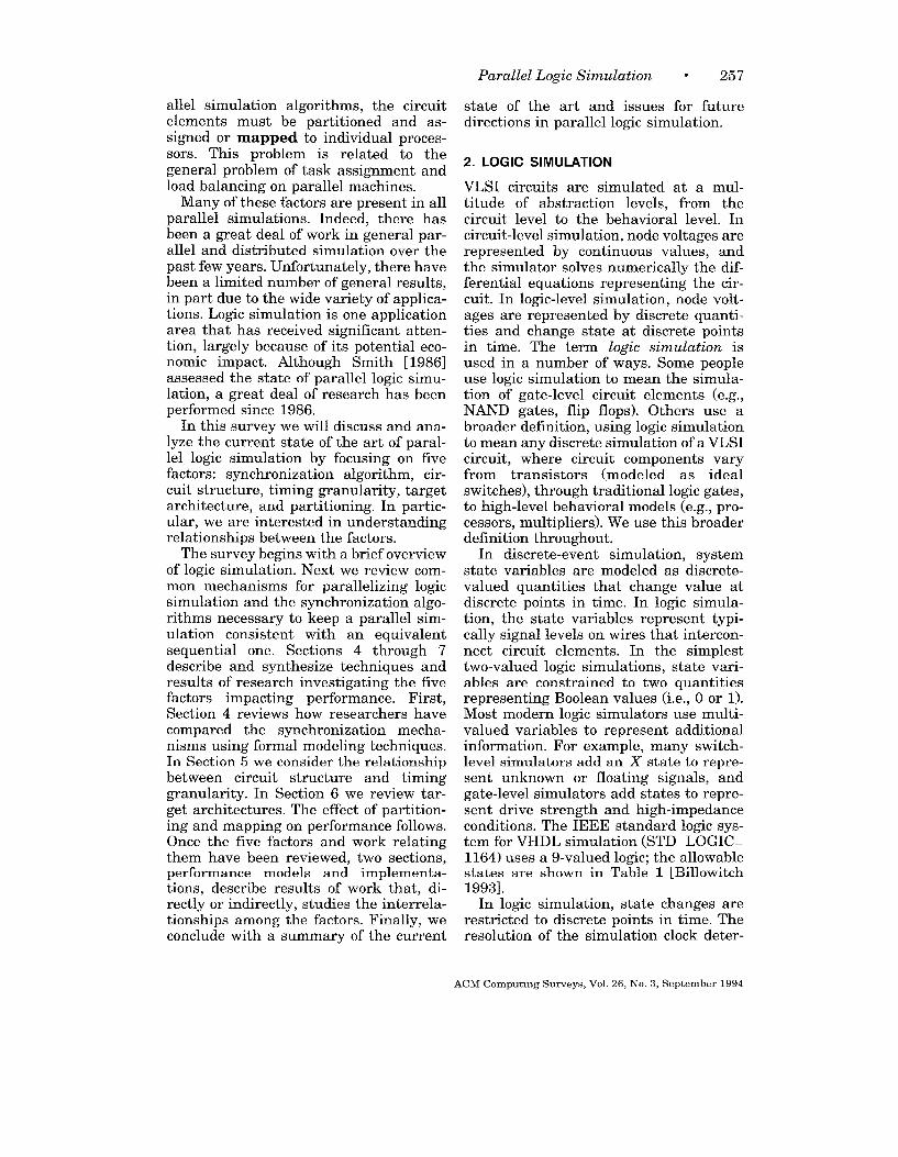
In discrete-e~ent simulation, systemstate variables are modeled as discrete-valued quantities that change value atdiscrete points in time. In logic simula-tion, the state variables represent typi-cally signal levels on wires that intercon-nect circuit elements. In the simrdesttwo-valued logic simulations, state ~ari-ables are constrained to two quantitiesrepresenting Boolean values (i.e., O or 1).Most modern logic simulators use multi-valued variables to represent additionalinformation. For examde. manv switch-level simulators add a; X’ state-to repre-sent unknown or floating signals, andgate-level simulators add states to rem-e-sent drive strength and high-impedanceconditions. The IEEE standard logic sys-tem for VHDL simulation (STD.LOGIC.1164) uses a 9-valued logic; the allowablestates are shown in Table 1 [Billowitch1993].
In logic simulation, state changes arerestricted to discrete points in time. Theresolution of the simulation clock deter-
ACM Computmg Surveys, Vol. 26, No. 3, September 1994
258 * Mary L. Bailey et al.
Table 1. IEEE Standard Logic System
State Purpose
u uninitialized state
x forcing unknown
o forcing zero
1 forcing one
z high impedance
w weak unknown
L weak zero
H weak one
don’t care
mines the allowable ~oints in time whenstate variables can change. This is re-ferred to as the timing granularity, andallowable time values are called timepoints or time steps. Using a fine gran-ularity, a simulator can model timing-dependent behavior more accurately,with the possible penalty of an increasein execution time. Simulators with acourse granularity provide little (if any)timing behavior, but generally havefaster execution. The specific impact oftiming granularity on performance is ex-amined in Section 5.
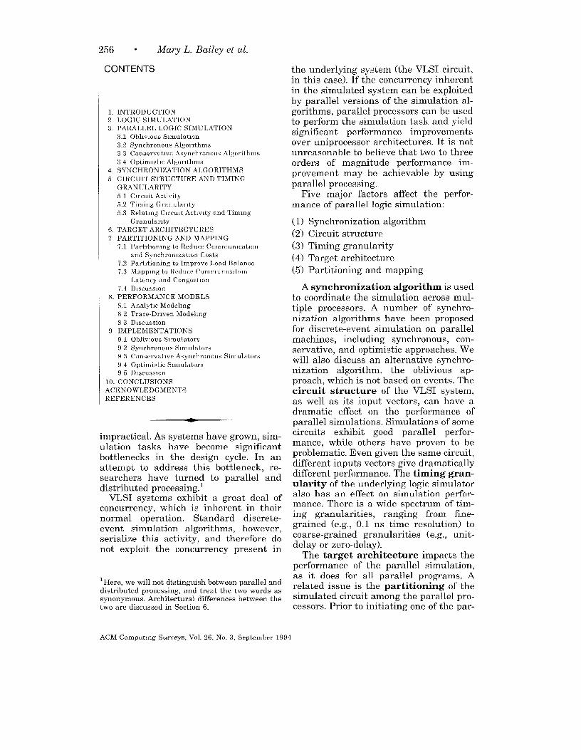
For simulation purposes, we model aVLSI system as a collection of logic ele-ments at varying levels of abstraction(e.g., transistors, NAND gates, flip flops,multipliers, etc.) and their interconnect-ing wires. Input vectors are then pro-vided to exercise the circuit. A gate-levelexample using three logic elements isshown in Figure 1. This example has twoinverters (labeled a and ~ ) and a singleAND gate (labeled y); the interconnect-ing wires are labeled a through e. Thedelay through each gate (the time re-quired for an input signal change to bereflected at the output) is indicated im-mediately below the gate.
State changes are represented byevents in the simulation, such as thechange in output value of an individualgate. As in general discrete-event simula-
2ns
Figure 1. Gate-level example circuit
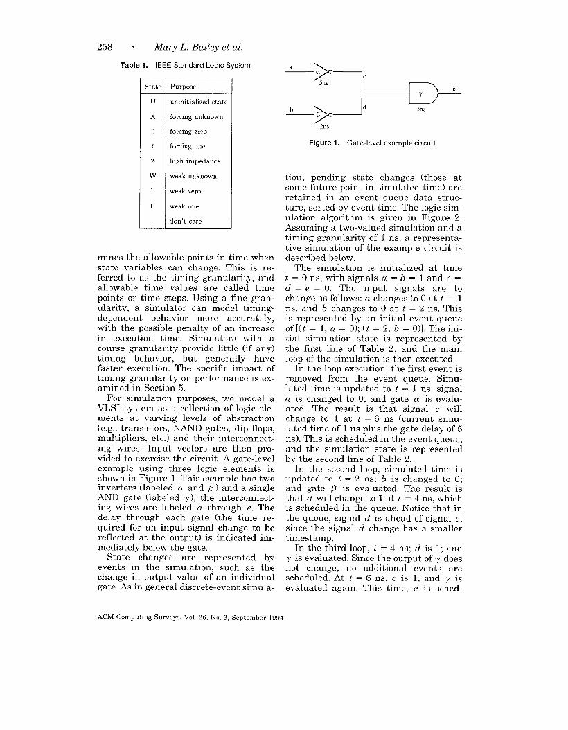
tion, pending state changes (those atsome future point in simulated time) areretained in an event queue data struc-ture, sorted by event time. The logic sim-ulation algorithm is given in Figure 2.Assuming a two-valued simulation and atiming granularity of 1 ns, a representa-tive simulation of the example circuit isdescribed below.
The simulation is initialized at timet = O ns, with signals a = b = 1 and c =d = e = O. The input signals are tochange as follows: a changes to O at t = 1ns, and b changes to O at t = 2 ns. Thisis represented by an initial event queueof[(t = 1, a = O); (t = 2, b = O)]. The ini-tial simulation state is represented bythe first line of Table 2, and the mainloop of the simulation is then executed.
In the loop execution, the first event isremoved from the event queue. Simu-lated time is updated to t = 1 ns; signala is changed to O; and gate a is evalu-ated. The result is that signal c willchange to 1 at t = 6 ns (current simu-lated time of 1 ns plus the gate delay of 5ns). This is scheduled in the event queue,and the simulation state is representedby the second line of Table 2.
In the second loop, simulated time isupdated to t = 2 ns; b is changed to O;and gate P is evaluated. The result isthat d will change to 1 at t = 4 ns, whichis scheduled in the queue. Notice that inthe queue, signal d is ahead of signal c,since the signal d change has a smallertimestamp.
In the third loop, t = 4 ns; d is 1;andy is evaluated. Since the output of y doesnot change, no additional events arescheduled. At t = 6 ns, c is 1, and y isevaluated again. This time, e is sched-
ACM C!omputmg Surveys, Vol 26, No. 3, September 1994
while (event queue is not empty)
retrieve next event from event queue
update simulated time to time of event
update gate output to new value
for each gate connected to gate output
evaluate logic function
if output changes then schedule change
in event queueendfor
endwhile
Figure 2. Simulation algorithm.
Table 2. Simulahon State
Time
t
o
1
2
4
~
9
Signals
abcde
11000
01000
00000
00010
00 1 1 0
Do 1 1 1
Queue
[(t=l,a=O);(t=2, b= O)]
[(t=2,b=O);(t=6 )c=l)]
[(t=4,d=l);(t=6,c= l)]
[(t=6,c= l)]
[(t=9,e= l)]
[1
uled to change to 1 at t = 9 ns. At t = 9ns, e is 1, an-d the event queue is empty.The final simulation state is representedby the last line of Table 2.
Note that even though the simulationran up to time t = 9 ns, the simulationloop was not executed 9 times (once perns). The loop was executed only 5 times
(once per required gate evaluation). Theevent-driven nature of the algorithm al-lows the simulator to skip time pointsthat have no circuit activity, therebyimproving performance (i.e., decreasingexecution time).
As VLSI integrated circuits increase insize (more than a million transistors on achip and climbing), the time required toexecute the simulation algorithm be-comes unacceptably long, even usingevent-driven techniques. This is due to anumber of factors. First, the number ofrequired functional evaluations grows asthe number of logic elements grows. Sec-
Parallel Logic Simulation ● 259
end, as the number of pending eventsgets larger, the overhead associated withmanaging the event queue increases.Third, with larger circuits, a larger num-ber of input vectors are needed to verifyproper circuit operation, further increas-ing the length of the simulation run.
For this reason, parallel machines arebeing investigated as a vehicle for in-creasing the performance of VLSI logicsimulations. The event-driven algorithm
(Figure 2) is serial in nature, executingevents in sequential order. However, thisis a limitation of the algorithm, not theVLSI system. For example, the evalua-tion of gates a and ~ could clearly beexecuted in parallel without altering theresults of the simulation.
There are, in fact, a number of waysthat parallelism can be exploited toimprove simulator performance[Mueller-Thuns et al. 1990]. Algorithmparallelism uses pipelining techniques toaccelerate the major loop by executingindividual program steps on differentprocessors (e.g., event queue manage-ment, functional evaluation). A limitedamount of parallelism is available usingthis technique, since there are a limitednumber of steps in the major loop. Dataparallelism uses different processors tosimulate the circuit for distinct inputvectors. This technique is quite effectivefor fault simulation, where a large num-ber of independent input vectors need tobe simulated. It is less effective, however,during design verification, where the goalis to minimize the completion time of anindividual input vector. Model paral-lelism, alluded to in the previous para-graph, uses different processors to per-form the functional evaluations for dis-tinct logic elements. When state changeson one processor affect the simulation onanother processor, a timestamped mes-sage is used to communicate both thestate change and the simulated time thestate change occurs in. A time synchro-nization algorithm is then needed to de-termine which functional evaluations cansafely be executed in parallel. This sur-vey concentrates on techniques for ex-ploiting model parallelism, exploring the
ACM Computing Surveys, Vol. 26, No, 3, September 1994
260 * Mary L. Bailey et al.
major factors that impact the perfor-mance of parallel logic simulation.
3. PARALLEL LOGIC SIMULATION
Prior to executing a parallel simulation,the logic elements are typically assignedto individual processors. The functionalevaluations for each logic element arethen executed by its assigned processor.To maintain correct simulation time, co-ordinating execution between processorsis crucial. The simulation clock is theusual mechanism for this coordination.
In sequential, event-driven simulation,events are typically maintained on atime-ordered queue. As events are re-moved from the queue, simulated time isupdated and the events evaluated, whichmay cause other events to be placed onthe queue. In parallel simulation, thereare often multiple queues, one per pro-cessor. Coordinating event evaluationsand managing these queues are neces-sary to ensure correct simulation. Thereare several mechanisms for ensuring cor-rectness; we refer to these as time syn-chronization strategies. We summarizethe most common synchronization strate-gies in this section. For a more completedescription of the current state of re-search in general parallel discrete-eventsimulation, see Fujimoto [1990].
3.1 Oblivious Simulation
The oblivious strategy is not eventdriven. Instead, all circuit elements areevaluated during every time step,whether or not their inputs have changed.The workload here is fixed for each timestep, so scheduling can be performedstatically at compile time, and noscheduling overhead is incurred at runtime.
Rank ordering is often used in thesesimulators as a means of scheduling ele-ment evaluations. All elements, gener-ally gates, are ordered according to theavailability of their inputs. Gates whoseinputs are also inputs to the simulationare at rank O. A gate is at rank i if all ofits inputs are produced by gates at ranks
less than i and at least one of its inputsis produced by a gate at rank i – 1. Eval-uating gates in rank order ensures that
(1) the inputs for all gates will be stable,(2) each gate will be evaluated a singletime, and (3) gates will be evaluated assoon as possible. In the example of Fig-ure 1, gates a and ~ are at rank O, andgate y is at rank 1.
To parallelize the oblivious algorithm,three approaches can be taken. The firstis to use a vector processor and designthe simulation so that identical opera-tions are performed on gates of a giventype at the same level. The second ap-proach is to use independent, general-purpose processors as a pipeline, evaluat-ing one rank on every processor. The thirdapproach schedules element evaluationsamong the processors by solving a gen-eral optimization problem, maximizingprocessor utilization while keeping thenumber of evaluations constant betweenprocessors and minimizing interproces-sor communication [Kravitz et al. 1991].
In oblivious strategies, the majorsource of overhead for logic simulation isredundant evaluation of elements whoseinputs have not changed. However, thecomputation per element is often muchless than that in event-driven strategies.Thus in comparing the two strategies,one must consider both effects. Let theamount of computation for an individualelement evaluation in the event-drivenstrategy be C times that in the obliviousstrategy. Additionally, assume that E isthe ratio of the number of events in theevent-driven strategy to the number ofevaluations in the oblivious strategy.Then for a sequential simulation, theoblivious strategy is preferred if E >I/C. Currently values for C are approxi-mately 100 for traditional simulators,making the oblivious strategy preferredif E > 0.01. Recently, techniques havebeen proposed that reduce C to between20 and 50, making the oblivious strategypreferred if E > 0.04 to 0.10 [Lewis1991].
Another criticism of the obliviousstrategy is the coarse timing model typi-cally used in these simulations. This crit-
ACM Computing Surveys, Vol. 26, No. 3, September 1994
Parallel Logic Simulation ● 261
icism has been addressed recently by theadvent of oblivious algorithms for finertiming models, but their impact on C is
unclear [Maurer and Lee 1994; Shriverand Sakallah 1992].
Comparing oblivious and event-drivenstrategies for parallel simulation is com-plicated by the addition of synchroniza-tion and communication mechanisms.Static scheduling is feasible for oblivioussimulations, resulting in still more sav-ings over the event-driven strategy. How-ever, low circuit activities still favor theevent-driven strategy. Large pipelinedcircuits may have enough activity tomake the oblivious strategy an attractivealternative to the event-driven strategy;more research is needed to determinewhen each strategy is preferred.
3.2 Synchronous Algorithms
The most obvious synchronization algo-rithm is to have all processors work onthe same time step in a synchronouslock-step fashion. Since the resultingsimulated time is common across all pro-cessors, this is also referred to as aglobal-clock algorithm.
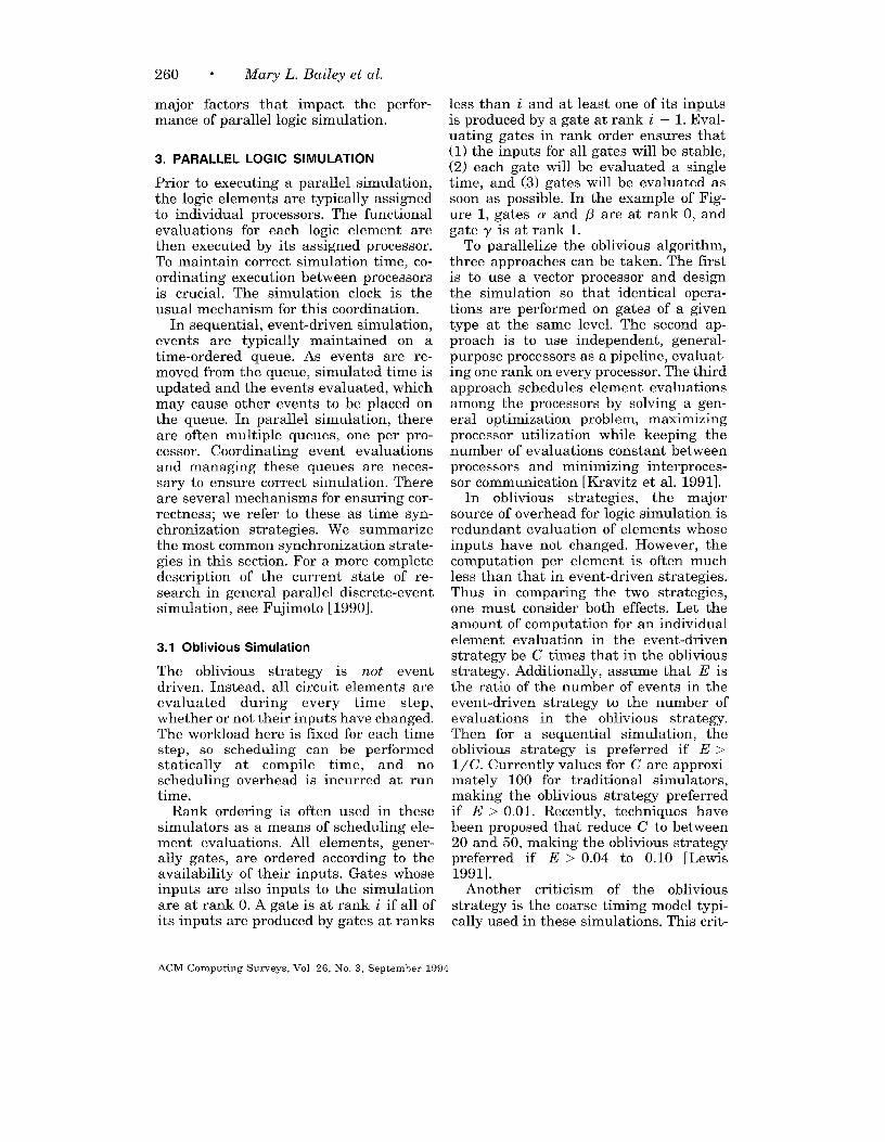
Consider the example simulation ofFigure 1, and assume each gate is as-signed to a distinct processor. The se-quence of operations in a synchronousalgorithm is illustrated in Table 3. Ini-tially (t = O ns), messages are deliveredfrom the primary inputs to gates a and~ describing the input vector. At globaltime t = 1 ns, a is evaluated, causing amessage to be sent from a to y with atimestamp of t = 6 ns; at time t = 2 ns,@ is evaluated, causing a message to besent from ~ to -y with a timestamp oft = 4 ns; at time t = 4 ns, -y evaluatesthe message from @ (the message withthe smaller timestamp); and at time t = 6ns, y evaluates the message from a,sending a message to the output for t = 9ns. Since no two evaluations occur at thesame point in simulated time, no paral-lelism is exploited in this example. Theamount of parallelism available in realis-tic circuits is examined in Section 5.
Time
o
1
2
4
6
Table 3. Synchronous Example
Evaluations
a
/3
Y
?
Messaees
m + a (t=l, a=O)
a+~ (t=6,c=l)
fl+~ (t=4,d=l)
~ + out (t=9,e=l) 1n + b (t=2,b=O)
The difficulties in this algorithm in-clude determining when all processorshave completed a time step and what thenext time step should be. Determiningcompletion can be accomplished with asimple barrier which may be supportedby the parallel architecture or software.Determining the next time step dependson how the events are managed. If thereis a central event queue, the central eventqueue simply finds the lowest time; how-ever, insertions and deletions from thequeue can serialize. When each processorhas a local queue, a global minimum op-eration must be performed. Additionally,another problem develops, that of loadbalancing. Because the processors willlikely have different numbers of eventsactive during a given time step, someprocessors may finish earlier than oth-ers, resulting in potentially significantload imbalance.
3.3 Conservative Asynchronous Algorithms
To reduce the problem of load imbalanceand central-queue contention, algorithmswhich allow the processors to proceed atindependent rates with independentqueues and clocks are attractive. If eachprocessor or logic element maintains itsown local simulation time, the algorithmis known as a local-clock or asynchro-nous algorithm. There are two classes oflocal-clock algorithms: conservative andoptimistic.2
2The synchronous algorithm described earlier canalso be classified as a conservative algorithm.
ACM Computing Surveys, Vol. 26, No. 3, September 1994
262 e Mary L. Bailey et al.
ac
(
bd
Figure 3. Local clock example.
Figure 3 shows the example circuitwith each gate assigned to an individualprocessor. The clock symbol associatedwith each processor indicates the factthat simulation time is maintained lo-cally, within the processor. The value ofthe local simulation time may thereforebe different from one processor to thenext.
Conservative asynchronous algorithmshave their origins in Chandy and Misra[1981], and Bryant [1977]. They requirethat the local simulated time associatedwith a logic element is only advanced tothe extent that the advance cannot vio-late causality in the system being mod-eled (i.e., before a logic element will ad-vance its local simulated time to t, itmust know that it will receive no addi-tional messages with timestamps lessthan t).In order to be able to draw con-clusions about the timestamps of mes-sages it might receive in the future, theconservative algorithms require thatmessages from one logic element to an-other be sent in nondecreasing time-stamp order.
To ensure compliance with the conser-vative requirements, two constraints areplaced on the logic elements. The first iscalled the input waiting rule, which con-strains the advancement of local simu-lated time to be the minimum timestampassociated with the last message receivedfrom any other logic element. Thus theinput waiting rule ensures that messagesare processed in timestamp order. Thesecond constraint, the output waitingrule, ensures that messages to other pro-
cesses arrive in timestamp order. Mes-sages waiting for output must not be sentbefore it is certain that all other outputmessages will have later timestamps. Ifdifferent events have different propaga-tion times (such as different rise and falltimes for a gate element), then outputevents must be queued to ensure that allmessages arrive in timestamp order. Anassumption is made here concerning theunderlying system, that it supports FIFOmessage delivery on each channel.
Consider the simulation of our exam-ple circuit, again assigning each gate to aseparate processor. The local time foreach gate is maintained independently,and is initialized at O ns. Table 4 showsthe sequence of operations in the conser-vative algorithms The first round ofmessages communicate the input vectorto a and ~. This updates their local timeto t = 1 ns and t = 2 ns, respectively.Gates a and /3 can then be evaluated (inparallel), triggering two messages to y.Two additional messages are sent fromthe inputs to a and ~, indicating nomore input changes will take place, up-dating their local times to t = CC. Theneed for these two messages will be de-scribed below. As a result of the inputwaiting rule, y‘s local clock can now beupdated to t = 4 ns.
All three gates can now be evaluated
(again in parallel), triggering two moremessages to y. Again following the inputwaiting rule, y can now update its localtime to t = 6 ns, since it now has a mes-sage from /? indicating no additionalmessages will come between t = 4 ns andt = 6 ns. Gate y is then evaluated, and amessage is sent to the output at t = 9 ns.
As another example, consider the cir-cuit in Figure 4. Assume that the propa-gation delay of each gate is 3 ns, andeach gate is on a separate processor. Thelocal clock of the processor containing thetop gate has a simulated time of 1 ns,while the local clock of the lower proces-
3We are using lookahead to relax the output wait-ing rule.
ACM Computing Surveys, Vol 26, No. 3, September 1994
Parallel Logic Simulation “ 263
Table 4. Conservahve Example
Local time Evaluations Messages
a~-r
o 00 m + a (t=l ,a=O) in + ~ (t=2,b=O)
120 ~, P a + -y (t=6,c=l) ~ + -y (t=4,d=l) in + a (t=co) in -+ @ (t=co)
cam 4 ~> P, Y Cl+ ’y(t=m) 0+-y(t=co)
Ooco 6 Y -y -+ out (t=9,e=l)
Set lQ bar
0->1 @ t=4 o @ t=33ns
Figure 4. Flip flop example circuit.
sor is at time 3 ns. The processor contain-ing the top gate can process the messagechanging the value of Reset from 1 to O,since the value of Qbar will not changeuntil after time 3 ns. However. the m-o-.cessor containing the lower gate cannotprocess the message changing the valueof Set at time 4 ns, because it cannotdetermine that the value of Q will notchange before time 4 ns, even though inthis example Q would not change untiltime 5 ns.
As presented above, the conservativealgorithm is prone to deadlock. For in-stance, if Qbar in the example is at time1 ns instead of time 3 ns, then neitherthe Set nor Reset change can take placebecause there is no assurance that eitherQ or Qbar will not change before time 2ns.
A number of techniques have been pro-posed to deal with the deadlock problem.These techniques can be broadly catego-rized into two classes: deadlock avoid-
ance and deadlock detection and recov-ery. Deadlock avoidance techniques usea special message type that has a time-stamp but no content (a null message)[Misra 1986]. Whenever a logic elementreceives a message, it must send a mes-sage on each of its outputs. If the simula-tion does not require a regular messageto be output on a channel, a null messageis sent in its place. The algorithm elimi-nates the potential for deadlock, but withthe penalty of increasing substantiallythe total number of messages required toexecute the simulation. In the first exam-ple, the messages from the input to gatesa and ~ at t = cc are null messages.
The deadlock detection and recoveryal~orithms allow the basic conservativeal~orithm to deadlock, detect the dead-lock condition, and invoke a recovery al-gorithm to break the deadlock [Chandyand Misra 19811. Deadlock detection al-gorithms can be- either centralized, typi-cally only detecting global deadlock, ordecentralized, typically using circulating-marker algorithms that can detect localdeadlock conditions. The deadlock recov-ery algorithm often depends upon thetype of detection algorithm used, but onealgorithm usable in all cases is to per-form a global minimum over all pendingsimulation events on all logical pro-cesses. The local simulated time cansafely be advanced to the result of thisglobal minimum operation, and theevents at that simulated time processed,thereby breaking the deadlock.
ACM Computing Surveys, Vol. 26, No. 3, September 1994
264 - Mary L. Bailey et al.
There are other conservative ap-proaches which have been reported inthe literature. These involve using
knowledge about the application to re-duce the overhead associated with theChandy-Misra algorithm. Lubachevsky[1989] uses a moving time window inwhich only events whose timestamp liesin the time window are eligible for pro-cessing. Lookahead is another approachwhich has been effective in reducingoverhead [Fujimoto 1989]. In this case, aprocess with local time t knows all eventsit will produce up to time t + L, where Lis the lookahead. In practice, logic gatesoften have a minimum delay, L, and will
not produce any events before time t + L,which can be used to reduce the numberof null messages sent.
3.4 Optimistic Algorithms
The original optimistic asynchronous al-gorithm, Time Warp, was devised by Jef-ferson [1985]. Here, whenever a messageis received by a logic element, the processadvances its local simulated time to thetimestamp on the message and simulatesthe effects of the incoming message. Thissimulated time advance is performed in-dependent of the fact that future mes-sages might have a lower timestamp,thereby potentially invalidating the workperformed when the original messagearrived.
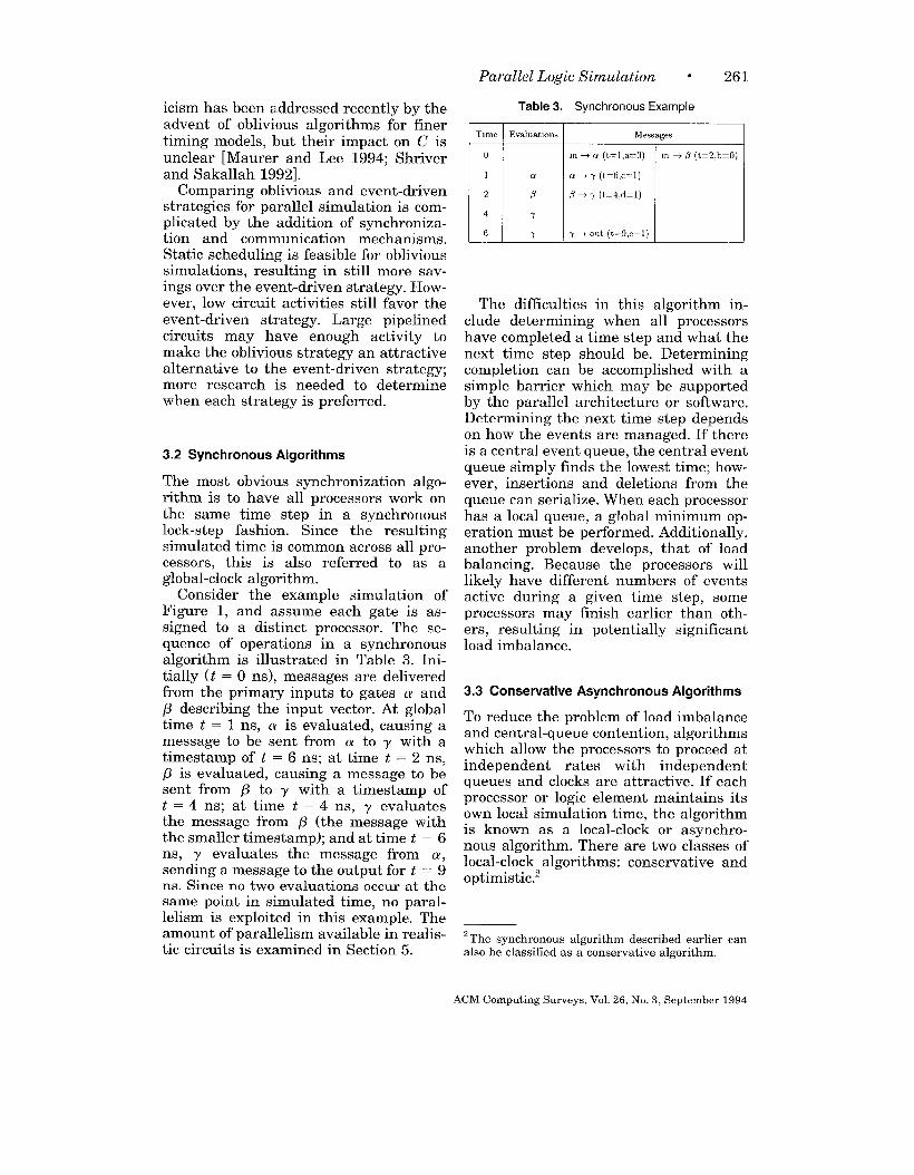
In the first example circuit (Figure 3),the simulation starts out as in the con-servative algorithm, with messages fromthe input to gates a and ~ (see Table 5).Gates a and ~ are both evaluated (inparallel), each sending a message to y.Both of these messages are evaluated byy, and the local time of y is optimisti-cally updated to t = 6 ns, assuming noadditional messages will come from /3between 4 ns and 6 ns. Gate y sends anoutput message for t = 9 ns.
In the second example circuit (Figure
4), both processors would process mes-
sages, assuming that no messages would
arrive “in the past.” If the top gate has a
delay of 3 ns, then this assumption holds,
and the simulation proceeds correctly.
Table 5. Ophmwtlc Example
I‘“’a’ “meI ‘Va’uat’on’I M.ssa’ge,
However, if the top gate has a delay of 1ns, then the lower processor has nowprocessed a message at time 4 ns and
will later receive a message at time 3 ns
(from Q). It must undo the damagecaused by processing the change to Setat time 4 ns. Thus, the event from Qtriggers a roll back, forcing the lowerprocessor to return to the state it hadbefore it evaluated the Set event. Addi-tionally, the event from Set could havecaused an erroneous event to be sent tothe top gate. To remove this event, anantimessage would be sent from the lowerprocessor to the top processor. If the an-timessage arrives before its correspond-ing real message is processed, both eventsare removed; otherwise the antimessagetriggers a roll back on the receivingprocessor.
In order to perform roll back, proces-sors must have saved the state of thecircuit. During a roll back, local simu-lated time is backed up to the value asso-ciated with the incoming message; thesystem state associated with the logicalprocess is restored from an earlier copy;and antimessages are sent out along out-put channels to invalidate any previouslytransmitted messages with timestampsgreater than the new local simulatedtime. When these antimessages are re-ceived at their destination logical pro-cesses, they may trigger roll back on thoseprocesses as well.
Clearly, the Time Warp algorithm re-quires overhead to perform roll backs andsave state. The saved state also takes upmemory. To reduce the memory require-ments, old states can be removed whenno longer needed. The minimum of theprocessors’ local times and messages intransit is known as the global virtual
ACM Computmg Surveys, Vol. 26, No. 3, September 1994
time (GVT). No message can arrive at aprocessor earlier than GVT, so statesand messages saved before GVT, calledfossils, can be discarded.
Gafni’s [1988] lazy cancellation strat-egy reduces the impact of roll back on theperformance of simulation. Instead of ag-gressively canceling previously sentmessages whenever roll back occurs, thelazy cancellation algorithm waits to can-cel the message until it is known that thewrong message had been sent. Thus, ifthe right event had been delivered forthe wrong reasons, the receiving proces-sor is not inhibited because of excessive
causality constraints.As with the conservative algorithms,
there are variants on the optimisticstrategy. One such variation is the Mov-ing Time Window (MTW) algorithm pro-posed by Sokol et al. [1988]. It attemptsto exploit the observation that the mostlikely events to be rolled back are thosethat are farthest ahead in simulated time.The MTW algorithm establishes a win-dow immediately ahead of GVT and onlyallows local simulated time for a logicalprocess to be advanced to a point withinthe time window. If an incoming messagehas a timestamp that is ahead of thewindow, it is placed in the local eventqueue and processed once GVT is ad-vanced enough that the timestamp fallswithin the window.
4. SYNCHRONIZATION ALGORITHMS
Comparing synchronization algorithmsfor general parallel simulations is diffi-cult. However, there has been some suc-cess in using formal models to comparethese algorithms in the logic simulationdomain. We summarize these resultshere.
While considering the effect of timinggranularity on circuit parallelism, Bailey
[ 1992bl considered two synchronizationstrategies: the synchronous strategy andan idealistic conservative strategy. Theidealistic conservative strategy is a lowerbound on the execution time for all con-servative algorithms (including both syn-chronous and conservative asynchro-
Parallel Logic Simulation “ 265
nous). She shows that if overheads areignored and all events have the sameevaluation time, the idealistic conserva-tive algorithm will perform at least aswell as the synchronous algorithm. Thetwo algorithms will perform identicallyfor unit-delay timing. Since synchronousalgorithms are generally simpler thanconservative asynchronous algorithms,then with reasonable load balancing, onewould expect a synchronous simulationto outperform a conservative asyn-
chronous simulation if unit-delay timingis used.
Bailey and Lin [1993] extend this workto include four different synchronizationstrategies: synchronous strategy, theconservative asynchronous strategy, theoptimistic asynchronous strategy, and theconservative optimal strategy. The con-servative optimal strategy is an artificialstrategy that uses knowledge of all eventsin the simulation to construct an optimalscheduling of events, with the constraintthat messages on a given processor areevaluated in timestamp order. Two as-sumptions were made for all synchro-nization strategies to keep the analysistractable. First, it is assumed that thereis a fixed, positive time delay associatedwith each logic element. This precludeselements from having a delay of zero,which can occur in some simulators. Thisalso precludes having different time de-lays for the same element, such as isfound in RNL [Terman 1983]. Second, itis assumed that every evaluation ele-ment is on its own processor.
Bailey and Lin’s first result shows thatthe synchronous strategy is slower thanthe conservative optimal strategy. Com-munication costs are assumed to be neg-ligible in the synchronous simulation,eliminating the costs of maintaining aglobal event queue and synchronizing atthe end of each time step. Next the con-servative optimal strategy is shown to befaster than the conservative asyn-chronous strategy with null messages.Communications costs for the conserva-tive asynchronous strategy are not as-sumed to be zero, although it is assumedthat the presence of null messages does
ACM Computing Surveys, Vol. 26, No. 3, September 1994
266 - Mary L. Bailey et al.
not degrade the performance of the sys-tem by increasing resource contention inthe communications structure or by tak-ing evaluation time on the target proces-sor. There are mixed results in compar-ing the synchronous and conservativeasynchronous strategies. If the circuit isstrongly connected, an unlikely situationfor a logic simulation, then the syn-chronous strategy will be faster. If thefanout is limited, then the conservativeasynchronous strategy may be superior.
The remaining results pertain to theTime Warp or optimistic strategy. Thecost of saving state is ignored, as well asthe cost of restoring state during rollbacks. Other roll back costs, such as thecost of sending antimessages, are in-cluded. Under these assumptions, TimeWarp with either aggressive or lazy can-cellation outperforms the conservativeoptimal strategy. The issue of limitedprocessors is also addressed. If all logicelements on a given processor are consid-ered as a single process, then the aboveanalysis holds. However, this means thatprogress is delayed until all inputs to thelogic block are known, as opposed to eachindividual logic element. This can de-grade performance. A similar problem oc-curs in Time Warp upon roll back. Underthis assumption the entire logic block isrolled back instead of rolling back justthe element which receives the antimes-sage. Without these restrictions, theabove results cannot be proven; more re-search is needed to address these issues.
Thus using simple analytic models,Bailey and Lin have shown that the opti-mistic synchronization strategy is pre-ferred, although several unrealistic sim-plifications were necessary in order toobtain these results. It would be nice toeliminate many of these simplificationsto determine whether these conclusionshold given the complex factors involvedwith implementing each algorithm onreal hardware.
5. CIRCUIT STRUCTURE AND TIMINGGRANULAR IN
The information inherent in the circuitbeing simulated and the input vectors
used to exercise the circuit can have alarge impact on the performance of thesimulation algorithm. Circuit structureincludes such aspects as circuit topology,circuit size, abstraction level, fanout,
feedback, circuit type, and circuit activ-ity.
Circuit topology refers to the intercon-nection pattern between circuit elements.The abstraction level is the underlyingmodel assumed for individual elements
(e.g., switch level, gate level, etc.). Thecircuit type classifies the circuit in termsof its design style and goals, distinguish-ing between combinational circuits andsequential circuits, clocked and self-timedcircuits. Circuit activity is concerned withthe dynamic nature of signal valuechanges—how frequently signals changevalue, number of simultaneous valuechanges, etc.
The interrelationships between circuitstructure and the other factors are signif-icant enough that it is difficult (if notimpossible) to isolate the impact that cir-cuit structure alone has on the perfor-mance of parallel simulation. For thisreason, the impact of circuit structurewill primarily be addressed in conjunc-tion with the other factors rather than inisolation. An exception to this is circuitactivity, which has received extensivestudy.
One of the best understood relation-ships among the factors affecting perfor-mance is that between circuit activityand timing granularity. Work in this areabegan by simply measuring circuit activ-ity. More recently, formal models havebeen developed that relate circuit activ-ity and timing granularity.
5.1 Circuit Activity
VLSI designers have long been inter-ested in measuring activity in their cir-cuits. Circuit activity has a broader in-terest than parallel logic simulation: forexample, it affects power requirementsin CMOS designs directly. In the early1970’s, Rattner instrumented a logic sim-ulator to measure the average numberof gates which were active during simu-
ACM Computing Surveys, Vol. 26, No. 3, September 1994
lation runs (personal communication).He found that, on average, approxi-mately 2.5 percent of the gates were onthe event queue at any given time duringa simulation run.
A few years later, research in circuitactivity increased due to its importancein event-driven parallel simulation. Thefocus changed from measuring the per-centage of simulation elements on theevent queue to the average number ofsimulation elements evaluated in thesame time step.
Frank [1985; 1986] published a fairlyextensive study of circuit activity as partof his work on a parallel data-driven logicsimulation engine, the Fast- 1. This simu-lation engine used an event-driven algo-rithm, so its potential speedup was influ-enced by the activity in the circuits.Frank did not directly measure circuitactivity, but rather estimated the poten-tial speedup of the parallel Fast-1 over auniprocessor version by considering thenumber of instructions the sequential andparallel versions required. The ratio ofthe number of sequential instructions tothe number of parallel instructions pro-vided an upper bound on speedup and arough estimate of the circuit activity. Us-ing 13 circuits ranging in size from 78 to20,300 transistors, he found potentialspeedups ranging from 4.1 to 192.1, witha mean of 49.5. The low values surprisedFrank, and he was not optimistic aboutthe potential for the parallel Fast-1engine.
Soon after Frank’s work, other expe-riments were performed using existingsequential simulators to consider the po-tential of parallel event-driven simula-tion. The metric used in these experi-ments is usually referred to as circuitparallelism, which is defined to be theaverage number of events executed peractive simulation time step. Time stepsin which no events are executed are ig-nored, since there is no overhead forskipping them in an event-driven simula-tor. Circuit parallelism provides an up-per bound on the speedup one can obtainusing a parallel, synchronous, event-driven simulator.
Parallel Logic Simulation ● 267
Wong et al. [1986] were the first toreport actual circuit parallelism mea-surements. They used a gate- andswitch-level simulator and measured theparallelism of five circuits ranging from650 to 8000 transistors, using fixed-delaytiming. The parallelism values rangedfrom 2.1 to 55 with an average of 18.6,They scaled these parallelism values toestimate the circuit parallelism of100,000 component circuits. The scaledvalues ranged from 80 to 3,294 with anaverage of 1,279. In contrast to Frank,Wong et al. were optimistic about thepotential for parallel simulation, basedon the scaled parallelism values.
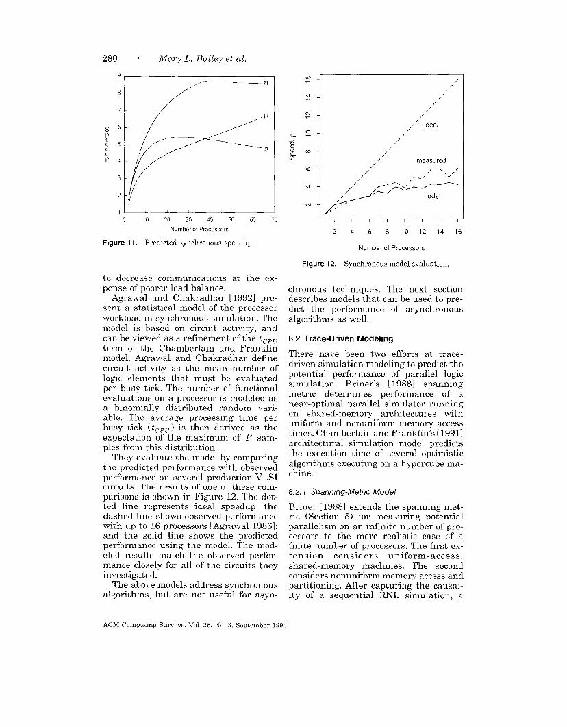
Soule and Blank [1987] and Soule[1992] were the first researchers to con-sider the impact of different abstractionlevels on circuit parallelism. Four differ-ent abstraction levels were presented: in-struction, behavioral, RTL, and gate.THOR, a multilevel, event-driven simu-lator, was used here to measure the ide-alized speedup of three circuits using thefour abstraction levels. Two of the cir-cuits (3400 and 5000 elements) were sim-ulated at the gate level. A third circuitwas simulated using a different func-tional simulator. The speedup measure-ments were obtained by simulating theevent trace with an “ideal” parallel simu-lator having no cost for scheduling, nomemory contention, and equal cost forevent evaluation. For 1000 processors,the speedup was less than 10 for all butone circuit and abstraction level, wherethe speedup was near 100. Additionally,they found speedup to be relatively con-stant over all four abstraction levels, andelement activity between O.1% and 0.5%at any particular time point.
During the following two years, Bailey[1992a] and Bailey and Snyder [1988]presented additional circuit parallelismmeasurements using the switch-levelsimulator RNL. RNL models a transistoras a resistance in series with a voltage-controlled switch and provides timing es-timates with 0.1 ns resolution [Terman1983]. The nine circuits used in thesemeasurements ranged from 200 to 61,600transistors. The resulting circuit paral-
ACM Computing Surveys, Vol. 26, No. 3, September 1994
268 ● Mary L. Bailey et al.
lelism values ranged between 2.8 and 23.The measurements in Bailey [1992a] in-cluded a different activity metric, thequeue metric, which corresponds moreclosely with Rattner’s early measure-ments. The queue metric measures theaverage length of the simulation queue.The values measured using the queuemetric will be higher than those foundusing the average parallelism, since therewill usually be additional elements onthe event queue which are not executedin the current time step. Using the samenine circuits, they found, on average, be-tween O.22’%Oto 8.9% of the nodes wereon the queue at each time step. Thesevalues have much more variance thanRattner found in his measurements.
Additionally, Bailey [1992a] presentsempirical evidence to demonstrate thatcircuit parallelism does not generallyscale linearly with circuit size as wasassumed in Wong’s optimistic paral-lelism measurements. In one circuit fam-ily, the shift register, parallelism didscale almost linearly. For other circuitfamilies, this was not the case. The par-allelism does generally increase with cir-cuit size, but it is not a simple linearfunction.
Rather than using circuit parallelismas the mechanism for defining activity,Briner [1988] and Briner et al. [1988]devised a new metric, the spanning met-ric, to estimate the potential for parallelsimulation using the interdependenceof model evaluations. Two additionalsources of parallelism are measured withthis technique. First, additional paral-lelism is measured because a signalchange may cause more than one modelevaluation due to fanout. If event han-dling is inexpensive compared to modelevaluations, this is a more accurate mea-sure of the parallelism available for sim-ulation. Second, just because events hap-pen at different times does not mean thatthere is a causal effect between them.Thus, events at different time steps maybe processed in parallel if model evalua-tions caused by the earlier event do notimpact the later event. By extractingcausal data from a sequential simulation,
Briner et al. estimated the parallel activ-ity in three circuits, ranging in size from700 to 15,000 transistors, and found val-ues ranging between 4.7 to 19.5. Theycompared this to the circuit parallelismfor the same circuits and found that thespanning metric provided 4 to 10 timesmore potential paralle 1 activity than wasfound using circuit parallelism.
Thus there have been several studiesof circuit activity over the past few years,with conflicting conclusions. There areseveral reasons for these differences.First, different researchers used differentmetrics for evaluating circuit activity.Second, different sequential simulatorswere used, having different model ab-stractions and different timing resolu-tions. Finally, different circuits wereused for the various measurements, re-sulting in differences due directly to thestructure of the individual benchmarkcircuits.
5.2 Timing Granularity
Logic simulation covers a broad spec-trum of model representations, each withdifferent timing granularities rangingfrom very fine-grained timing (such as0.1 ns) to coarse-grained timing (such aszero-delay). Timing granularity can sig-nificantly impact simulator performance.Simulators using fine-g-rained timing at-tempt to model time accurately in thesimulator. Often these simulators use atime resolution in the range of 0.1 ns orsmaller. An additional issue in flne-grained simulators is whether a givenelement always has the same delay. Forinstance, some gate-level simulators mayuse a single delay for a given gate type,independent of the output value of thegate. Others have different delays de-pending on output capacitance andwhether the signal is rising or falling. Intransistor-level simulators with fine-grained timing, delay computations canbe even more complex, resulting in a largenumber of different possible delays for asingle signal. We will consider fine-grained timing to include both small timeresolutions and a large number of possi-
ACM Computing Surveys, Vol 26, No, 3, September 1994
ble delays in the circuit. As either thenumber of possible delay values de-creases or the time resolution increases,we say that the timing resolution iscoarser.
Unit-delay and zero-delay timing areat the extreme of the coarse-grained tim-ing granularities. Both are quite commonin logic simulations. Unit-delay timingassumes that every element has a propa-gation delay of one unit. Zero-delay, usedfor sequential circuits, is even coarser.Here, only functionality is preserved,with no attempt to measure timing.
5.3 Relating Circuit Activity and TimingGranularity
The effect of timing granularity on cir-cuit activity has been investigated viaboth empirical studies and formal mod-els. The first empirical study was an ex-tension of Bailey’s [1992a] earlier circuitparallelism results. A unit-delay simula-tor, SwitchSim, was used to measure thecircuit parallelism of the circuits previ-ously measured using RNL. SwitchSim,written by Frank, is based on the algo-rithms developed for the Fast- 1 simula-tion engine. The circuit parallelism mea-sured by the unit-delay simulator wasalways larger than that measured byRNL. The parallelism values ranged from35 to 593 on circuits ranging in size from200 to 61,600 transistors. These valueswere larger than the RNL measurementsby factors ranging from 3.6 to 25.8.
Even though this work compared theeffect of two different timing granulari-ties on circuit parallelism, it failed toprovide a good characterization of therelationship between timing and paral-lelism. However, Bailey [ 1992b; 1993] hassince developed two formal models tocompare the effects of time resolution oncircuit parallelism. Both models beginwith the same initial abstraction, a graphrepresenting the execution of a given cir-cuit. In the graph, nodes correspond toevents in the simulation, and edges rep-resent causality. It is assumed that nomore than one change occurs at any in-stant in time; an infinite resolution clock
Parallel Logic Simulation ● 269
is used for timing. It is also assumed thatexactly one event causes a subsequentevent. These two assumptions ensurethat the graph is a tree. Edges in the treeare labeled with the delay between theevent and its parent. Because of the infi-nite resolution clock, every event is in itsown time step, and there is no circuitparallelism.
In order to investigate the relationshipbetween parallelism and time resolution,each model has a mechanism for increas-ing the timing granularity of the simula-tion. In the time-based model, events areplaced in time steps of larger resolutionsby their simulation time, preservingcausality constraints [Bailey 1992b]. Thisdiffers from the way in which simulatorsplace events into time steps, but the re-sulting analysis is simpler. For example,consider the situation with three depen-dent events, the first one occurring attime O, the second at time 1, and thethird at time 4. If the simulation clockhas a time base of 2, these events areplaced in time steps O, 2, and 4, respec-tively using the time-based model. Usingthis model, it can be shown that circuitparallelism is a nondecreasing functionof time resolution. The parallelism foundusing unit-delay timing provides an up-per bound on the circuit parallelism forall time resolutions.
In the second model, the delay-basedmodel, events are placed in time stepsaccording to the delays between events[Bailey 1993]. This corresponds moreclosely to the placement of events in ac-tual event-driven simulators, so it is morerealistic than the time-based model. Inthe above example, the last event isplaced in time step 6 rather than timestep 4 since the delay between it and itsparent event is 3. Unfortunately, the re-sults obtained from this model are morecomplex than those in the time-basedmodel, and circuit parallelism is no longera nondecreasing function of time base.There are instances where increasing thetime base actually decreases parallelism.However, as the resolution increases, cir-cuit parallelism tends to increase or re-main constant. More precisely, Bailey
ACM Computing Surveys, Vol. 26, No, 3, September 1994
270
00Q
o010
00
0
. Mary L. Bailey et al.
A
A
A+ +-+
iLd o
: AA+/!
11 1 [ I 1 1 I
-1
0
considers
10000 30000 50000Number of Circuit Elements
A Bailey, unit delay, switch level
A Badey, O 1ns res., switch level
+ Briner, O 1ns res., gate level
O Briner, 0.1 ns res., switch level
+ Soule, course res., various levels
X Wong, 1ns res., gate& switch level
Legend
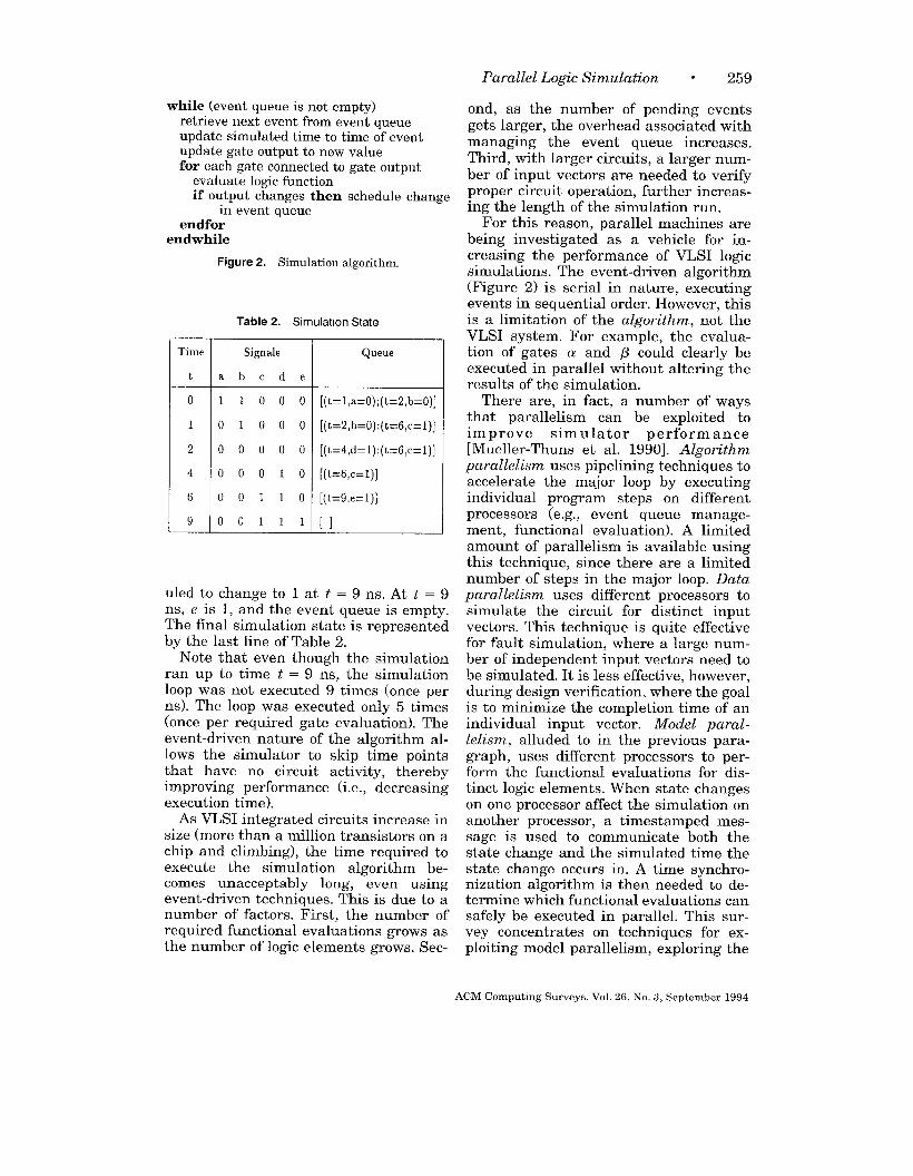
Figure 5. Average parallelism measurements.
measurements taken with coarser timingthe familv of all circuits withthe same unit-del~y parallelism. Theunit-delay parallelism provides an upperbound on the circuit parallelism for thesecircuits, over all time resolutions. Thelower bound on the circuit parallelism forthese circuits is a nondecreasing functionof time resolution, which equals theunit-delay parallelism when the timeresolution is sufficiently large. Baileyconfirms the delay-based model predic-tions by effectively changing RNL’s timeresolution and measuring the resultingeffects on circuit parallelism.
Figure 5 shows a composite graph ofmany of the parallelism results [Bailey1992a; Briner 1990; Soule and Blank1987; Wong et al. 1986]. Included aremeasurements from a variety of timinggranularities (fine-grained, fixed-delay,and unit-delay), and from a variety ofabstraction levels ranging from switch tofunctional. The largest parallelism valueis obtained from the largest circuit usingthe coarsest timing granularity (unit-delay). In order to view the results forthe smaller circuits better, an enlarge-ment of the lower left quadrant of thefigure is shown in Figure 6. Overall, thehigher parallelism values result from
granularities, as predicted by Bailey’smodel. It is not clear whether the ab-straction level makes a significant differ-ence in the measurements, but the typeof circuit (together with its input vectors)appears to make a significant difference.
Thus we have evidence that coarser-grained timing can result in dramaticallyhigher levels of circuit parallelism, andthere is a definite relationship betweentiming resolution and circuit activity. Ifhigher levels of circuit activity imply bet-ter performance by parallel simulators,then coarser-grained timing appearsmore promising for parallel simulators.Note that the results do not cover alltiming granularities, for example, zero-delay timing. Additionally, the range ofparallelism measurements, even usingthe same simulator, indicate that circuitactivity also depends on other aspects ofcircuit structure. Unfortunately, thesestudies shed little light on the exactnature of these relationships.
6. TARGET ARCHITECTURES
Parallel architectures are classically par-titioned into MIMD (multiple-instruc-
ACM Computmg Surveys, Vol 26. No. 3, September 1994
Parallel Logic Simulation ● 271
A
A +=
x
,4
++
A
+
A~ OA
1
0 5000 10000 15000Number of Circuit Elements
A Bailey, unit delay, switch level
A Bailey, 0.1 ns res., switch level
+ Briner, 0.1 ns res., gate level
O Briner, 0.1 ns res., switch level
+ Soule, course res., various levels
X Wong, 1ns res., gate& switch level
Legend
Figure 6. Average parallelism measurements for small circuits.
tion, multiple-data) machines, whereeach processor executes code indepen-dently, and SIMD (single-instruction,multiple-data) machines, where all pro-cessors execute the same instruction onindependent data [Flynn 1966]. MIMDmachines can be further classified asshared memory, where a common globaladdress space is used to implement datasharing and synchronization betweenprocessors, or distributed memory, wherecommunications is via explicit messages.
In SIMD architectures, processors exe-cute instructions synchronously in lock-step. Processors may be programmed toavoid computing during a step if desired.Since all processors must perform thesame instruction, only one type of gate ismodeled at a time. A table lookup is oftenperformed to help mitigate this restric-tion. If there are many types of models
(as is the case in hierarchical systemdescriptions), simulation performancewill be greatly diminished. Processors areoften connected by a grid which allowsneighboring processors to communicatequickly with each other. If nonadjacentprocessors must communicate, the mes-
sages must be routed through otherprocessors or a global router. This is typi-cally more expensive than nearest-neighbor communication. Most logic sim-ulations are not limited to nearest-neighbor communication, complicatingpartitioning and mapping.
Shared-memory MIMD architecturesutilize a common global address space tocommunicate between processors. Small-scale parallelism is typically imple-mented via a bus architecture, in whichprocessors contend for access to a singlephysical memory located on the bus.These machines exhibit a uniform mem-ory access time, independent of the pro-cessor or memory address. When thenumber of processors is large, a general-purpose interconnection network is usedto communicate between memory mod-ules associated with each processor. Inthese machines, memory access times arenonuniform, and depend upon whetherthe referenced address is local or remote.Communication between processors isrelatively fast, usually on the order ofmicroseconds. Depending on the inter-connection network, however, contention
ACM Computing Surveys, Vol. 26, No. 3, September 1994
272 0 Mary L. Bailey et al.
can be a problem. On a bus-based archi-tecture with common memory and localcaches, contention for the bus, false shar-ing, and protocol overhead can be veryexpensive. On machines which havenonuniform memory access, one of thepartitioning goals is to avoid excessivecommunication to slower remote mem-ory.
In distributed-memory MIMD architec-tures, the memory associated with eachprocessor is local to that processor, andcommunication between processors ishandled via explicit messages. These ma-chines are typically constructed using ascalable topology, such as a mesh, torus,or hypercube. Message latencies can belong relative to functional evaluationtimes. If a signal being transmitted fromone processor to another happens to beone of the circuit’s synchronization sig-nals, simulation performance can be seri-ously degraded [Briner 1990],
A parallel execution platform that hasbecome increasingly popular is a networkof workstations. Generally similar in styleto distributed-memory MIMD machines,these platforms have several uniquefeatures. Their communication capabili-ties are strongly influenced by the factthat message delivery is via a general-purpose network. This implies signifi-cantly longer message latency. Also, mul-tiple users are often executing programswhile tightly coupled multicomputers of-ten are dedicated resources.
In addition to general-purpose ma-chines, there have been a number of spe-cial-purpose architectures proposed andbuilt to implement parallel logic simula-tion [Blank 1984; Goering 1988]. Unlikegeneral-purpose machines, these enginestypically restrict the type of simulationthat can be performed. Usually a singlesynchronization mechanism is employed,and only limited modeling levels areavailable. Many industrial companieshave built logic simulation engines. Forexample, the Yorktown Simulation En-gine [Denneau et al. 1983; Pfister 1986]and EVE [Beece et al. 1988] were de-signed at IBM; the MARS accelerator wasdesigned at AT&T [Agrawal and Dally
1990]; NEC built HAL [Takasaki et al.1986]; Fujitsu developed the SP [Saitoh1988]; and Zycad Corporation manufac-tures an entire line of machines. Addi-tionally, several logic simulation engineshave been proposed and/or prototype inuniversities; the Munich Simulation En-gine [Hahn 1989] and a modified dataflow architecture [Mahmood et al. 1992]are two of these. In this survey we willnot focus on logic accelerators, althoughmany of the issues discussed here alsopertain to the effectiveness of these en-gines.
7. PARTITIONING AND MAPPING
The placement of circuit elements on theprocessors of a parallel machine cangreatly affect the simulation of a VLSIsystem. One goal of partitioning ele-ments for parallel simulation is to adjustthe balance of computation among pro-cessors by assuring that each processorhas useful work. The most common tech-nique attempts to achieve load balanceby ensuring that processors have a nearlyequal number of components. However,this technique assumes that all compo-nents are equally active. Both Soule andBlank [1987] and Briner et al. [1988]have shown that a circuit’s activity isusually uneven during simulation andvaries over time. Further, it is difficult toknow a priori which parts of the circuitwill be active concurrently. Some re-searchers have performed a preliminarysimulation to detect circuit behavior, pro-viding more information for partitioning[Briner 1990; Chamberlain and Hender-son 1994; Maanjikian and Loucks 1993].Others have investigated the feasibilityof dynamically adjusting the partition,allowing the simulator to adjust to cir-cuit activity [Kravitz and Ackland 1988;Nicol and Reynolds 1985].
Another goal in placement is to reducecommunication, which can represent amajor performance bottleneck. Channelsmay become congested. Communicationrequires message-handling time and ad-ditional event-scheduling time. It alsostresses the synchronization algorithm;
ACM Computing Surveys, Vol 26, No. 3, September 1994
Parallel Logic Simulation 8 273
as a signal crosses processor boundaries,the synchronization mechanism must en-sure that the signal is properly handled.Per message synchronization costs arelow for synchronous simulation but can
be high for the asynchronous techniques.In optimistic algorithms, the probabilityof a roll back is proportional to the proba-bility of a message being received [Briner1990]. In conservative algorithms, withmore communication channels the likeli-hood of deadlock is higher, or, in dead-lock avoidance algorithms, additionalnull messages must be sent [Soule andGupta 1992].
Finally, mapping is related to commu-nication. Mapping allocates partitions toprocessors. On machines with differentinterprocessor communication times, it isbest to place frequently communicatingpartitions closer to reduce message la-tency and congestion. This problem hasnot been thoroughly investigated but hasreceived some attention [Davoren 1989;Nandy and Loucks 1992].
7.1 Partitioning to Reduce Communicationand Synchronization Costs
The most actively pursued area in parti-tioning has focused on reducing commu-nication and synchronization overhead.In order to account for load balance, mostpartitioning research that focuses oncommunication ensures an equal numberof gates are assigned to each processor.We illustrate a number of the more com-mon algorithms using the example cir-cuit of Figure 7, a two-bit full adder.
Levendel et al. [1982] present a parti-tioning method based on strings. The al-gorithm follows a primary input to afanout gate and selects one of the fanoutgates to add to the string. The processcontinues to a primary output. The gateson the string are placed on the sameprocessor. If nodes remained unassigned,one is randomly selected to start a newstring until no more nodes remain. In theexample of Figure 7, a possible stringassociated with input a includes gates 1,4, 5, and 7. The string associated withinput b then includes only gate 3, since
a
b1
.
Figure 7. Partitioning example circuit.
the fanout of gate 3 is already assignedto another string, The string of input c isgate 2; the string of input d is gates 6, 9,
and 10; and the string of input e is gate8. For a two-processor simulation, assign-ing strings a and b to processor 1 leaveshalf of the gates for processor 2. Theresulting partitioning is illustrated inFigure 8(a). Note that the resulting par-titioning is highly dependent upon thechoices of fanout gates used to build thestrings and the ordering in which thestrings are constructed. The algorithm isfast and ensures that at least one fanoutgate will be on the current processor.However, the algorithm fails to reducecommunication of closely related compo-nents significantly. Agrawal [1986] ex-tends this algorithm to account for tim-ing delays of gates in the circuit so thatmore concurrency may be exploited.
Smith et al. [1987] introduce fanin andfanout cones to improve the problem ofcommunication. A cone of gates is gener-ated by processing the gates in rank or-der. Each gate has a cone consisting ofthe set of gates which are affected by theoutput of the gate. Once the cones arebuilt for all gates, the gates driven byprimary inputs are evenly assigned toprocessors. After the primary inputs havebeen assigned, a gate is randomly se-lected. The gate’s cone set and the unionof cone sets associated with all gates al-ready placed on each processor are com-
ACM Computjng Surveys. Vol. 26, No 3, September 1994
274 ● Mary L. Bailey et al.
Figure 8. Example partitioning results.
pared. The processor which has the
largest set in common is selected for thegate. After a processor is full, it is nolonger considered for assignment. Theyreport that this is fairly fast and reducescommunication greatly when comparedto a simple organization which placesgates on the same processor if they are ofthe same rank.
We illustrate this algorithm usingfanin cones, starting from the primaryoutputs and working back to the primaryinputs. Table 6 shows the fanin cones foreach of the gates in the example circuit.Starting from the primary outputs, wearbitrarily assign gate 2 to processor 1
(d)
Table 6. Fanm Cones for Example Clrcult
Gate Gates m Fanin Code Gate Gates m Farm Code
1 1 b~
~ 1, 2 ‘? 1,3,4, 5, 6, 7
3 3 8 8
4 1, 4 9 1, 3,4, 5, 6, 9
I 5 11,3,4,5 II 10 I1,3>4,5,6,8,9,1O ]
and gates 7 and 10 to processor 2. Choos-ing gate 5 at random, we note that it hasmore overlap with the cones of gates 7and 10, so it is assigned to processor 2.
ACM Computmg Surveys. Vol 26. No. 3. September 1994
Choosing gates 6 and 8 at random re-sults in the same conclusion, assignmentto processor 2. Since half of the gates arenow on processor 2, the remaining gatesare assigned to processor 1. This resultsin the partitioning illustrated in Figure8(b).
Mueller-Thuns et al. [1993] believe thatthe cost of communication in a paralleland distributed environment is the majorfactor in obtaining speedups in parallelsimulation. To reduce communication,they place entire cones on a processorwithout regard to whether the gateswithin the cone have already been placedon another processor (a gate may be inmore than one cone). This leads to redun-dant evaluation of gates. The partition-ing problem then becomes which cones toplace on which processor rather thanwhich gates to place on which processor.To reduce communication between cones,they use a depth-first search on the in-puts to cones, forming a tree. Thus, leafcones of the tree are likely to be on thesame processor and have a parent coneon the same processor.
One common variation on cone parti-tioning is to form the partitions startingfrom latches in addition to primary out-puts. This limits interprocessor commu-nication to clock events, decreasing syn-chronization overhead. This technique isparticularly attractive for zero-delay,rank-order simulation and obliviousalgorithms.
Bisection and multiway partitioningare graph-partitioning algorithms whichhave been used extensively in placementand routing problems [Fiduccia andMattheyses 1982; Kernighan and Lin1970]. In both, the components aretreated as nodes, and signals are treatedas arcs in a graph. The goal is to dividethe graph recursively into partitions tominimize arcs between partitions. A bi-section of the example circuit is illus-trated in Figure 8(c), with only a singlearc connecting the two partitions. Briner[1990] shows that for optimistic timesynchronization, bisection improvesgate-level simulation greatly over ran-dom methods where the cost for func-
Parallel Logic Simulation ● 275
7=+
-i356=
3
%5n
j4gn3$ ‘ ~COMP/Wunbound
+ -COMPILAZ16400– e -coMP/LAz/1600
a -- x- coMP/LAz/4oo>.— 1 .- + best random3
c?o1 1 I I 1 io 4 8 12 16 20
processors
Figure 9. Random vs. bisection partitioning of atransmtor network.
tional evaluations is similar to com-munications costs. However, manualpartitioning can be far superior whenavailable. Figure 9 shows that for atransistor-level simulation using lazycancellation, a good random partitioningis better than a bisection partitioning.This is true even when various sizes ofmoving time windows are used. Randompartitioning performs better than the bi-section partitioning because, for transis-tor-level simulations, model evaluationsdominate the computation, and the ran-domness of the data provides better loadbalance. Load balance is achieved at thecost of communication and synchroniza-tion overhead (roll backs). The side ef-fects of roll backs, repeated model evalu-ations, are diminished by the use of lazycancellation.
Sporrer and Bauer [1993] have per-formed a number of experiments on par-titioning circuits. Using the rank-ordertechniques of Smith et al. [1987] (placingcuts at elements of the same rank),Sporrer and Bauer achieve good load bal-ance, but nearly 30’% of all signals mustcross between processors. They also im-plemented a bisection technique based onFidducia and Mattheyses [ 1982] whichreduces the number of boundary signalsto 1O–2O7O. They present a modified clus-tering technique which goes through twophases: fine-grained clustering and
ACM Computmg Surveys, Vol. 26, No. 3, September 1994
276 ● Mary L. Bailey et al.
course-grained clustering. In the firstphase, they use either a flip flop cluster-ing algorithm or the corolla-partitioningtechnique of Dey et al. [1990] to formsmall clusters. Flip flop clustering placesgates in small clusters near flip flops.Corolla partitioning detects reconvergentsignals, creating what is knmvn as apetal. Figure 8(d) shows two petals in theexample circuit. Overlapping petals arethen grouped into disjoint sets calledcorollas. In the second phase of the parti-tioning, the clusters are grouped togetherinto larger clusters while minimizing thenumber of interconnections. The flip flopclustering technique reduces the numberof signal crossings to around 4~o, andcorolla partitioning reduces signal cross-ings to around l%.
Simulated annealing is a commonmethod for reducing interconnections inphysical design. Thus, it seems appropri-ate to consider it for reducing communi-cation in logic simulation. Frank [19851and Chamberlain and Franklin [1990]have both used simulated annealing topartition circuits prior to simulation.However, this work has been hindered bytwo factors. First, the time required toperform the simulated-annealing task islong relative to the serial execution timeof the simulation. Second, the lack ofinformation about circuit activity prior tosimulation limits the ability to formulatean effective cost function to drive thesimulated-annealing algorithm. Someperformance predictions for circuits par-titioned with simulated annealing arepresented in Section 8.
7.2 Partitioning to Improve Load Balance
The easiest and fastest partitioning tech-nique is random partitioning, in whichelements are randomly assigned proces-sors [Chamberlain and Franklin 1990;Frank 1985; Kravitz and Ackland 1988;Smith et al. 1987]. This ensures goodload balance. If a portion of the circuit
(e.g., an ALU in a CPU) is active, thatportion of the circuit is distributed (e.g.,bit-slices of the ALU) across the proces-sors for simulation rather than concen-
trated on a single processor (which maybe the result in a partitioning algorithmthat stresses a reduction in communica-tion). Smith et al. [1988] show that ifmodel evaluations take significantly moretime than communication, random parti-tioning does a much better job of ensur-ing concurrency than cone partitioning.However, if the cost of communication isof the same order as functional evalua-tion, closely related elements need to beon the same processor to avoid communi-cation and synchronization overhead.
Wong and Franklin present an algo-rithm which attempts to minimize com-munication while maintaining processorbalance [ 1987b]. The basic method is touse an undirected graph with vertices torepresent gates and edges to representinterconnections between gates. A vertexis selected for each processor such thatall selected vertices are at least somedistance D away from each other. Subse-quent vertices are added to each proces-sor in a breadth-first, round-robin fash-ion. Partitioning the circuit of Figure 7,we start with gates 3 and 8 initially onprocessors 1 and 2, respectively. In round2, gate 5 is added to processor 1 (since itis adj scent to gate 3), and gate 10 isadded to processor 2 (being adjacent togate 8). In round 3, gate 1 is added toprocessor 1, and gate 6 is added to pro-cessor 2. In round 4, gate 7 is added toprocessor 1, and gate 9 is added to pro-cessor 2. Finally, in round 5, gate 4 isadded to processor 1, and gate 2 is leftfor processor 2. The resulting partition-ing is the same (in this case) as thestrings algorithm and is illustrated inFigure 8(a). Analytic comparisons withrandom partitioning show that thisheuristic partitioning is up to twice aseffective for several circuits on a bus-based architecture. However, later re-lated work shows that for a hypercubeexecuting a synchronous algorithm, ran-dom partitioning outperforms frequentlythe heuristic partitioning, while theheuristic shows better potential for usewith the optimistic asynchronous algo-rithm [Chamberlain and Franklin 1990;1991].
ACM Computing Surveys, Vol 26, No. 3, September 1994
Parallel Logic Simulation * 277
The above algorithms all make the im-plicit assumption that the computationalload associated with individual gates isconsistent across the circuit. This as-sumption is not valid, however, since thefrequency of evaluation of individualgates can be significantly different. Toaddress this issue, Manjikian and Loucks[1993] focus on redundant computationin cone partitioning by extending theprocess to do presimulation to get better
information about load balance. Ratherthan counting the number of componentsin a cone for maintaining load balance,they measure the activity of each coneand any overlapping subcones from pre-simulations. With this information, theythen perform iterative improvement[Sanchis 1989] that attempts to mini-mize the difference between the total ac-tivity per processor (including repeatedactivity) and the total activity in auniprocessor simulation. To avoid puttingall cones on the same processor, we mayonly move cones from larger cone sets tosmaller ones, and once moved, they can-not be moved again.
The use of presimulation to character-ize gate activity is supported in a studyby Chamberlain and Henderson [1994],who measured the predictive power ofpresimulation on a number of circuits.They showed that, at least for sufficientnumbers of random input vectors, pre-simulation is an excellent predictor ofsubsequent gate activity.
Another technique for handling loadbalancing is to adjust the partitions dy-namically. Nicol and Reynolds [1985] usehistories to determine when to reparti-tion. Using Bayesian decision processes,they develop a model to decide when thecost of repartitioning is worth the ex-pected improvement in concurrency. Forrepartitioning they suggest using a min-cut (bisection) with clustering algorithm.
Kravitz and Ackland [1988] performedstudies of the simulations of two circuitsand found that dynamic partitioning of atransistor-level simulation on a dis-tributed-memory machine was not effec-tive. Theoretically, dynamic partitioningcould be more effective than static parti-
tioning, but their results showedmarginal gain even if partitioning wasdecided with an omniscient scheduler.However, the measurements were per-formed using relatively small circuits
(about 10,000 transistors), and it is un-clear whether their conclusions hold forlarger circuits.
7.3 Mapping to Reduce CommunicationLatency and Congestion
A related problem is mapping partitionsto processors. On machines with uniformmemory access, mapping is not of con-cern. However, for machines which havenonuniform memory access, the proxim-ity of partitions can affect message de-lays and congestion. Few investigationshave been attempted in this area.
Using the hierarchical structure of adesign, Davoren [1989] defines localitytrees as an approximation technique forreducing communication between proces-sors. A locality tree uses a circuit’s hier-archical definition to define a tree ofcomponents. These components are thenarranged within the tree so that thosecomponents which communicate aremapped closer together. One should notethat physically connected componentsmay not necessarily communicate witheach other but just pass informationthrough them; thus, proximity alone isinsufficient and may not necessarily beavailable early in the design.
Returning to the example two-bit adderof Figure 7, a hierarchical decompositionmight place one bit of the adder on pro-cessor 1 and the other bit of the adder onprocessor 2. This results in the partition-ing illustrated in Figure 8(c). Note, it isnot surprising that this is the same re-sult as bisection, since the underlyingstrategy of the two algorithms is similar(i.e., group-connected components to-gether). Davoren’s results show perfor-mance increases of 208!Z0 when scalingfrom a network of 8 to 64 transputers fora circuit of 1060 gates using a conserva-tive algorithm.
Nandy and Loucks [1992] study anumber of factors including load balance,
ACM Computing Surveys, Vol. 26, No 3, September 1994
278 ● Mary L. Bailey et al.
2 4 6 8 10
Number of Processors
Figure 10. Random, iterative improvement, map-ping, and optimal partitioning of a gate-level simu-lation.
partitioning and mapping. They use aniterative improvement technique similarto Manjikian and Loucks [1993] but in-stead focus on the cost of nets crossingpartitions rather than the cost of re-dundant computations. On a networkof transputers using a conservativeasynchronous paradigm, they achievespeedups on the average of 4.5 on verysmall circuits. By adding weights to thecommunication arcs, they are able to mapthe partitions on the transputer to ac-count for its nonuniform message rate.Figure 10 displays the theoretical opti-mal performance of the simulator using atechnique similar to Briner [19881 versusiterative improvement partitioning, iter-ative improvement partitioning withmapping, and random partitioning. Ofparticular note is that performance isincreased an additional 10–20%0 whenthe target architecture’s communicationlimitations are considered.
7.4 Discussion
Research clearly shows that effectivepartitioning and mapping depends on anumber of factors: the computation\ corn-munication ratio, the circuit activity
(especially variation in location of activ-ity), and the target architecture’s com-munication capabilities. In static parti-tioning, a random partitioning works wellfor both conservative and optimistic syn-chronization algorithms when functional-evaluation time dominates communica-tion time. However, when functionalevaluations are not as costly, bisection,corolla, clustering, and Wong andFranklin’s [ 1987b] heuristic outperformrandom partitioning for optimistic syn-chronization techniques because commu-nication and synchronization overheadsare reduced. Because different circuitsand simulation models were used, it isdifficult to compare the different tech-niques. While many authors report thecut size, cut size alone does not guaran-tee better performance because circuitactivity may vary, leading to load imbal-ance.
For synchronous simulation, cone-partitioning methods have lead to goodperformance. Iterative improvement oncone partitioning with presimulation datahas reduced the number of redundantcomputations while cone levelization re-duces communication. When available,manual partitioning has performed ex-tremely well. To date, simulated anneal-ing has not proven effective both due to alack of a good cost function and excessiveexecution requirements. One possible im-provement is to use presimulation datain the cost function formulation.
The problems of mapping to nonuni-form memory access machines and of dy-namic and incremental partitioning havenot been thoroughly investigated. Map-ping has improved the performance oftransputer-based parallel simulation.Techniques for detecting when to reparti-tion have not been well defined, and theoverhead costs associated with reparti-tioning may overshadow any gain in per-formance. However, this mechanism maybe the only way to handle a circuit’s dy-namic behavior. Research is needed tounderstand the tradeoffs in these areasbetter.
Finally, it should be noted that mostresults in the literature have ignored the
ACM Computmg Surveys, Vol 26, No 3, September 1994
Parallel Logic Simulation ● 279
cost of simulation preparation: if it takeslonger to partition a circuit than simu-late it, what use is there in acceleratingthe simulation? Most of the partitioningtechniques discussed are linear in thesize of the circuit. However, is this reallyfast enough? For regression testing, whenlarge numbers of input vectors are used,partitioning costs are not as significantas they are early in the design phasewhen only a few vectors may be needed.To speed partitioning, it is also possibleto use parallel processing [Nandy andLoucks 1993].
8. PERFORMANCE MODELS
Now that the factors that impact the per-formance of parallel logic simulation havebeen described, we present methods toassess the likelihood of achieving accept-able performance in realistic scenarios
(i.e., ones that include the impact of mul-tiple factors). There have been a numberof performance models developed to in-vestigate parallel simulation, includingboth analytic and trace-driven modeling.Even though the final say in perfor-mance is the measurement of a real im-plementation, performance models havedistinct advantages: they are consider-ably faster to develop than full-fledgedimplementations, and they can charac-terize performance over a larger range ofparameters than is practical (or evenpossible) with implementations alone.
8.1 Analytic Modeling
An analytic performance model of thesynchronous simulation algorithm wasoriginally developed by Wong andFranklin [1987a], who considered aspecial-purpose architecture dedicated tologic simulation. It was extended byChamberlain and Franklin [1988] to in-clude hierarchical component modelingon a general-purpose, distributed-mem-ory machine. The performance model as-sumes a synchronous algorithm execut-ing on a hypercube architecture. Circuitcomponents are statically allocated toprocessors and do not migrate during ex-
ecution. If the simulation runs for B busyticks (simulation time points that haveone or more events that need to be evalu-ated), the execution time for P proces-sors is expressed as
RP = B . [max(tcru, tcoMM) + t~Y~cl
where tcpu is the average processor exe-cution time per busy tick; tcoMM is theaverage communications time per busytick; and t~yNc is the time required tosynchronize at the end of a busy tick. Theprocessor and communications times arecombined using a maximum operator toreflect the fact that computation andcommunications can occur simultane-ously (provided the memory bandwidth isnot saturated). The synchronization timemust be added to the maximum since itsexecution does not overlap with eitherevent processing or data communica-tions.
The variables in the above expressioncan be expressed as a function of sim-ulation properties (e.g., event counts,functional-evaluation counts, etc.) andarchitectural properties (e.g., functional-evaluation time, message formulationtime, message delivery time, etc.). A com-plete derivation and explanation for themodel is given in Chamberlain andFranklin [1990]. Using technology pa-rameters typical of an nCUBE 2 machineand input parameters measured from se-rial simulations of three benchmark cir-cuits, the model provides predicted per-formance for a number of distinct parti-tioning strategies [Chamberlain andFranklin 1986; 1990].
Figure 11 shows the predicted speedupover a single-processor implementation,R ~/RP, for one of the benchmark cir-cuits, Curves are presented for three dif-ferent circuit partitionings: random (R),Wong and Franklin’s heuristic (H), andsimulated annealing (S). Random parti-tioning performs the best, because per-formance is limited by load balancerather than communications require-ments. The heuristic and simulated-an-nealing partitioning algorithms attempt
.4CM Computing Surveys, Vol. 26, No. 3, September 1994
280 ● Mary L. Bailey et al.
9, (
s:eduP
8 -
7 -
6
5
4
3
,~o 10 20 30 40 50 60 70
Number of Processors
Figure 11. Predicted synchronous speedup.
to decrease communications at the ex-pense of poorer load balance.
Agrawal and Chakradhar [1992] pre-sent a statistical model of the m-ocessorworkload in synchronous simul ~tion. Themodel is based on circuit activity, andcan be viewed as a refinement of the tcputerm of the Chamberlain and Franklinmodel. Agrawal and C!hakradhar definecircuit activity as the mean number of10Ac elements that must be evaluatedp~r busy tick. The number of functionalevaluations on a processor is modeled asa binomially distributed random vari-able. The average processing time perbusy tick (trP,r) is then derived as theexpectation of-the maximum of P sam-ples from this distribution.
They evaluate the model by comparingthe wredicted ~erformance with observedperkrmance o’n several production VLSIcircuits. The results of’ one of these com-
parisons is shown in Figure 12. The dot-ted line represents ideal speedup; thedashed line shows observed performancewith up to 16 processors [Agrawal 1986];and the solid line shows the medictedperformance using the model. The mod-eled results match the observed perfor-mance closely for all of the circuits theyinvestigated.
The above models address synchronousalgorithms, but are not useful for asyn-
CD .,,...’
* /,..”
,.,”’cd ,,. ”
“’” ideal0
,.. ”
a.,..
;,.. ”
,/Q~
,.. ”% ,.” measured
..”
~ wL i I 1 # I 1 i 1
2 4 6 8 10 12 14 16
Number of Processors
Figure 12. Synchronous model evaluation.
chronous techniques. The next sectiondescribes models that can be used to pre-dict the performance of asynchronousalgorithms as well.
8.2 Trace-Driven Modeling
There have been two efforts at trace-driven simulation modeling to predict thepotential performance of parallel logicsimulation. Briner’s [1988] spanningmetric determines performance of anear-optimal parallel simulator runningon shared-memory architectures withuniform and nonuniform memory accesstimes. Chamberlain and Franklin’s [1991]architectural simulation model predictsthe execution time of several optimisticalgorithms executing on a hypercube ma-chine.
8.2.1 Spanning-Metric Model
Briner [1988] extends the spanning met-ric (Section 5) for measuring potentialparallelism on an infinite number of pro-cessors to the more realistic case of afinite number of processors. The first ex-tension considers uniform-access,shared-memory machines. The secondconsiders nonuniform memory access andpartitioning. After capturing the causal-ity of a sequential RNL simulation, a
ACM Comput]ng Surveys, Vol 26, No 3, September 1994
Parallel Logic Simulation w 281
trace-driven simulation is performed on
the data. The trace-driven simulation
uses techniques from the task assign-ment literature [Gonzalez 1977] to ac-count for scheduling on a finite numberof processors. Measurements of threesmall circuits show that near-perfectspeedups are possible up to the maxi-mum speedup of the unlimited processor
case.Briner extends the model of task as-
signment to consider the problem of dataaccesses in a machine with a nonuniformmemory architecture. His results showthat data assignment is a difficult prob-lem and that poor assignment reducespotential parallelism by at least a factorof two below the uniform memorymodel.
8.2.2 Architectural Simulation Model
Chamberlain and Franklin [19911
access
devel-oped an architectural simulation of sev-eral parallel simulation algorithms exe-cuting on a hypercube architecture, First,a circuit description and random set ofinput vectors are simulated on a stan-dard uniprocessor, and trace data is col-lected. Second, the circuit is staticallypartitioned using the heuristic of Wongand Franklin [ 1987 b]. Third, the tracedata, partitioned circuit description, ar-chitecture description, and parallel-al-gorithm description are input into an ar-
chitectural simulator that performs atrace-driven simulation.
Data is collected for three differenttime synchronization strategies. The firstis an optimal algorithm that is not at-tainable in practice but bounds the po-tential performance. The second two areboth optimistic asynchronous algorithmsusing aggressive cancellation: the basictime warp (TW) algorithm and a movingtime window (MTW) variant. The opti-mal bound is found by determining themost heavily loaded architectural re-source (either processor or communica-tions link) and observing that this re-source must be on the execution’s criticalpath. The execution time is then modeledas the workload performed by this re-
source. Note that this execution time isoptimal only for a giuen partitioning,A different allocation of circuit compo-
nents to processors will yield a differentoptimal performance.
Figure 13 compares the speedup pre-dicted for two different benchmark cir-cuits. The most notable conclusion fromthese curves is the extreme variation in
performance from one circuit to the next.Using TW, benchmark 1 (Figure 13(a))has speedup less than unity (i.e., the par-allel execution is slower than the serialexecution) for 32 processors, while bench-mark 2 (Figure 13(b)) has near-optimalperformance. One also notices a phe-nomenon in which the speedup curveshave more than one local maxima. Thisphenomenon has also been observed in
TW simulations for other application do-mains [Lin and Lazowska 1991],
Note that the MTW algorithm will oc-casionally perform noticeably better thanthe TW algorithm, and rarely performappreciably worse. To some extent, it issuccessful in decreasing the frequency
(and resulting performance degradation)of roll back.
8.3 Discussion
Both analytic and trace-driven perfor-mance models allow us to draw a numberof conclusions. First, parallel logic simu-
lations can have significant performanceadvantages over serial simulation. Thus,there is the potential for parallel logic
simulation to have a real economic im-pact in the design automation commu-nity. Second, the interrelationships be-tween the factors and the combination offactors that would ensure good perfor-mance are still not well understood. Forexample, widely varying performance ispredicted for optimistic algorithms fordifferent processor populations, differentcircuits, and different partitionings.Third, a good partitioning algorithm isessential, as poor partitionings degradeperformance seriously.
What remains to be accomplished is tounderstand better how individual factors(or combinations of factors) impact per-
ACM Computing Surveys, Vol. 26, No. 3, September 1994
. Mary L. Bailey et al.
. optimum a+ MTW
O TW
8: +P o
+
c
-t
-i\ I 1 1 1 1 1
0 10 20 30 40 50 60(a) Number of Processors
0 optimum
+ MTW
o -rW
e @
a @
o9 +
o
w
(B
B
t r r 1 I I
o 10(b)
20 30 40 50 60Number of Processors
Figure 13. Architectural simulation.
tunately, different implementations areformance. The analytic models need to berefined to rely less on empirical input
data. For example, the circuit activity inAgrawal and Chakradhar’s model mustcurrently be measured from simulationexecutions, If it could be reasonably pre-dicted from the circuit structure and\orinput vectors, conclusions could be drawnabout the appropriateness of the syn-chronous algorithm for a particular in-stance without having previously run thesimulation. The trace-driven modelshave, to date, only been used to predictthe execution time for a small number ofdata points, and several factors impact-ing performance differ from one datapoint to the next. Controlled experimentsusing trace-driven models need to varyonly a single factor at a time to helpquantify the impact each factor has onperformance.
9. IMPLEMENTATIONS
In addition to formal studies and perfor-mance modeling, a number of parallelsimulators have been implemented usinga variety of synchronization strategies.Implementations give the most accuratefeedback on actual performance. Unfor-
often difficult to compare, since they tendto vary across multiple factors. We pre-sent the implementations via their syn-chronization strategy and compare themat the end of the section.
9.1 Oblivious Simulators
As well as being used in hardware accel-erators, the oblivious approach has beenconsidered for use on general-purpose,parallel computers. Kravitz et al. [19911addressed the feasibility of mapping theunit-delay simulator COSMOS [Bryantet al. 19871 onto SIMD computers. Thisimplementation was able to take advan-tage of both course-grained parallelismfrom many simultaneous element evalu-ations and fine-grained parallelism usedto evaluate the Boolean equations repre-senting the behavior of each element. Be-cause of static scheduling, the equationscan be rank ordered, and the evaluationof each rank comprises an atomic opera-tion. A simple model of processors andinterconnection structures is used in theparallel COSMOS implementation, plac-ing significant scheduling demands onthe compiler.
ACM Computing Surveys, Vol 26, No 3, September 1994
Parallel Logic Simulation ● 283
Two relatively small circuits (of 20,000and 43,000 transistors) were used to
evaluate the performance of parallel
COSMOS. The effectiue parallelism, theaverage number of Boolean operatorswhich can be evaluated concurrently,provides an upper bound on the speedupthat can be obtained using the obliviousstrategy and includes the redundantevaluations of elements whose inputshave not changed. The effective paral-lelism for one circuit achieved a maxi-
mum value around 2500, while the othercircuit reached a lower maximum near
400. These high speedups are not gener-ally attainable in practice, due to com-
munications and scheduling constraints.
To measure actual speedups, a prototype
parallel COSMOS simulator was imple-mented on the Thinking Machines CM-2
[Hillis 1986]. This simulator used a sim-
ple SIMD model, and thus did not exploitthe full power of the Connection Ma-chine’s instruction set. Using this paral-
lel simulator, one circuit simulation ran
at twice the speed of sequential COS-
MOS, while the other only ran at half
that of sequential COSMOS. These cir-
cuits are relatively small, and the au-
thors expect better performance with
larger circuits.
Jun et al. [ 1990] proposed a variant of
the oblivious strategy for use in gate-level
simulation, where some care was taken
to minimize memory usage and time
spent in simulating feed-back loops. It
uses a segmented waveform relaxation
method in conjunction with bit-wise op-
erations. The segmented waveform relax-
ation method is used to divide the simu-
lation interval into a number of subinter-
vals, each of which can be represented by
a single word. Each element’s state dur-
ing a subinterval is represented by a sin-
gle word, and bit-wise operations can be
performed on the entire word to propa-
gate behavior throughout the circuit.
Logical shifts are used to represent
gate delays, Parallel computation is
used in two ways: (1) to evaluate gates at
the same rank order and (2) to pipeline
the subintervals in the waveform evalua-
tions. While the authors report good per-
formance on the ISCAS combinationalbenchmarks [Brglez and Fujiwara 1985]using a single processor, no results were
available for the parallel implementa-
tion,
9.2 Synchronous Simulators
Several parallel logic simulators use syn-
chronous algorithms. Soule and Blank
[19881 implemented a synchronous simu-lator on a 16-processor Encore machine.Speedups ranging from 4 to 9 were
obtained on circuits ranging in size
from approximately 500 to 5000 using 15
processors.
Mueller-Thuns et al. [ 1990] have syn-chronous implementations for two differ-ent abstraction levels of logic circuits:
switch level and gate level. For switch-
level simulation, they preprocess the
original “flat” transistor netlist to create
an acyclic set of strongly connected com-
ponents. These components are then used
as tasks and are available for scheduling
on a parallel processor. As in the work of
Jun et al., parallelism is obtained by
evaluating strongly connected compo-
nents in parallel during the same time
unit if they have the same rank order,
and by evaluating components in differ-
ent ranks in parallel if the time for the
component with lower rank is greater
than that for the component with higherrank. Using these techniques, they ob-tain speedups ranging from 2.21 to 7.56on circuits having approximately 10,000to 34,000 transistors using 8 processorsof an Encore multiprocessor.
For their gate-level circuits, clocks atlatches are used as the synchronizationmechanism [Mueller-Thuns et al. 1993].The circuit is partitioned according to theinput cones of latches (or primary out-puts). All gates on a path between pri-mary inputs (or outputs of other latches)and primary outputs (or inputs to latches)are on the same processor, creating asimple combinational circuit. Once allprimary inputs and outputs of latchesare known, a zero-delay simulation isperformed which allows updating of theprimary outputs and latches. After these
ACM Computing Surveys, Vol. 26, No, 3, September 1994
284 “ Mary L. Bailey et al.
have stabilized, signals are propagatedto other processors, beginning anothercycle. This algorithm has been imple-mented on both shared-memory anddistributed-memory parallel processors.Using 8 processors, they obtainedspeedups ranging from 4.6 to 4.9 on thedistributed-memory machine and 4.8 to
5.0 on the shared-memory machine usingthree example circuits from the ISCAS-89benchmarks [Brglez et al. 1989]. The cir-cuits ranged in size from just under18,000 to almost 24,000 gates.
Bataineh et al. [ 1992] implemented a
synchronous event-driven algorithm for agate-level simulation on the Cray Y-MP.They used both vectorization and paral-lel processing to process all events in agiven time step in parallel. For this tech-nique to perform well, they report thatthere needs to be 32 events available foreach of the 8 processors at each timestep. Using two example circuits, a com-binational circuit from the ISCAS-85benchmarks and a linear-feedback shiftregister, they found that there wereenough events in each time step and ob-tained speedups of 36 over a scalar ver-sion running on the Cray for the ISCAScircuit (2406 gates), and 52 for the shiftregister (size not reported). Thus thecombination of vector and parallel pro-cessing resulted in good speedups.
9.3 Conservative Asynchronous Simulators
As a part of Soule and Blanks [ 1988]parallel implementation of a gate-leveland register-transfer-level simulator,they implemented a conservative asyn-chronous algorithm using deadlock de-tection and recovery. They obtained
speedups of 7 to 11 for circuits of size 100to 5000 elements on a 16 processor En-core. They found that this mechanismworked more efficiently than the syn-chronous algorithm when more than 10processors were utilized.
Despite the early promise of conserva-tive algorithms, Soule and Gupta [ 1992]show that large circuits cause frequentdeadlock and that deadlock resolution re-quires 50–807c of the total execution
time. With deadlock avoidance, they esti-mate that 20 to 100 null messages wouldhave to be sent for each real message.
Thus, they conclude that deadlock detec-tion and recovery are more likely to suc-ceed. In a study to detect the sources ofdeadlock in the conservative algorithmspecific to digital simulation, Soule andGupta found four sources of deadlock:feedback to registers, multiple paths withdifferent delays, the simulation algo-rithm’s order of updating nodes, and de-sensitized nodes. They are able to per-form a number of optimizations with thisinformation. By exploiting element be-
havior, deadlock can be avoided. For ex-ample, since a register’s output onlychanges on a clock, the time of the nextoutput can be predicted, taking advan-tage of lookahead. Combinational circuitsthat are desensitized (e.g., an AND gatewith a zero input) produced no events,allowing signals to other inputs to beignored until the critical signal changes.Passing information about the lookaheadof the sensitized signal directly to af-fected nodes avoids the overhead of pass-ing a message through the desensitizedcombinational circuit. Grouping elementstogether into a single element reducesboth event handling and the probabilityof a deadlock. Speedups of 16–32 on anideal multiprocessor with 64 processorsare predicted for circuits of size 5000–25,000. However, these results are self-relative, Even with these optimizations,they conclude that for most circuits theconservative algorithm will be 2.8 to 3.5times slower than a synchronous algo-rithm.
Su and Seitz [ 1989] considered a num-ber of variants of the conservative asyn-chronous strategy on distributed-memoryMIMD machines. All variants used dead-lock avoidance; they differ in minimizingthe number of null messages by sendingthem in a “lazy” fashion. They used InteliPSC machines to measure the speedupof a 1376-gate multiplier network. Usinga 128-node iPSC\ 1 they obtain speedupsof approximately 10, and on a 16-nodeiPSC/2 they obtain speedups of 2 for thebest variant. They conclude that if the
ACM Comput]ng Surveys, VO1 26, N. 3. September 1994
Parallel Logic Simulation ● 285
time to process null messages is com-parable to the time to process actualmessages, then the conservative asyn-chronous algorithm will not perform wellwhen the number of m-ocessors is small.
To reduce the ove~head of null mes-
sages, they study a conservative asyn-chronous algorithm which groups multi-ple circuit elements together into a single
element. Elements in a single group aresimulated via a sequential algorithm,while different groups use the conserva-tive asynchronous strategy. They use a1067 -~ate self-timed FIFO circuit to eval-uate this algorithm, and achieve muchmore promising results using a smallnumbers of processors, especially if thecircuit is manually partitioned.
Ackland et al. [1985] and Kravitz andAckland [ 1988] have implemented a MOStiming simulator on a message-basedmultiprocessor using a conservativeasynchronous algorithm. While their tim-ing simulator provides continuous wave-forms, it uses discrete-event simulationtechniques to communicate between sub-circuits. Speedups from 7 to 20 are re-ported on a 60-processor system. Onething to note with these results is thatthe ~ming simulator requires much morecomputation per element evaluation thana logic-level simulator, and thus commu-nication overhead is less critical.
Subramanian and Zargham [ 1990] pre-sent a parallel, demand-driven simulatorfor a Sequent Balance. In demand-drivensimulation, results are requested at theoutput nodes, and requests propagateback to the input nodes. Extensive mem-ory is required as events propagate to thein~uts. The ~arallel version takes advan-
ta~e of glob~l memory by allowing pro-cessors to use a central task queue whichsupports better load balance. Using 5processors, randomly devised combina-tional circuits of 500 gates show speedupsof 2 to 3 times a sequential implementa-tion. Larger simulations on larger paral-lel m-ocessors are needed to make a fair.comparison with the Chandy-Misra-Bryant approach.
Chung and Chung [ 1990] implementedthree conservative algorithms for gate-
level simulation on the Connection Ma-chine CM-2, an SIMD architecture. Thefirst is a synchronous algorithm, usinga global clock. The second is a null-message implementation of the conserva-tive asynchronous algorithm with no
lookahead. The third algorithm addsIookahead to the asynchronous algo-rithm. Two circuits were used to measurethe performance of these algorithms; a16-bit combinational multiplier from theISCAS-85 benchmarks (2406 gates) anda 32-bit array multiplier (8000 gates). Allthree of these algorithms outperformTime Warp on the Connection Machine,in part due to the complexity of the TimeWarp implementation. Among the threealgorithms, the algorithm using looka-head outperforms the other two in mostcases, although when the number of in-puts is small, the synchronous algorithmperformed best for the smaller multi-plier. Due to memory limitations in theConnection Machine, large circuits mayrequire the synchronous algorithm, sinceits memory requirements are less thanthose for the conservative algorithms.
Arvind and Smart [19911 implementedELSA, a framework for event-driven logicsimulation in a nonuniform memory en-vironment. This framework supports bothconservative and optimistic synchroniza-tion strategies, as well as a hybrid strat-egy. The conservative synchronizationstrategy uses deadlock avoidance withnull messages. To lessen the cost of send-ing and processing null messages, theirnumber is minimized by eliminating re-dundant ones. ELSA is implemented in0ccam2 on a transputer-based multipro-cessor. Three multiplier circuits are stud-ied. Speedups over a uniprocessor are notreported, because the minimum numberof transputers used is 8 or 16, depend-ing on the circuit. However, the exe-cution gains appear fairly dramatic—onecircuit executes 3.6 times faster on 40transputers than on 16.
9.4 Optimistic Simulators
There have been several VLSI systemsimulators implemented using optimistic
ACM Computmg Surveys, Vol. 26, No. 3, September 1994
286 ● Mary L. Bailey et al,
techniques, The earliest simulator wasbuilt by Arnold, who reports on a LANimplementation [Arnold 1985; Arnold andTerman 1985]. The internals of RSIM[Terman 1983] were changed for parallelsimulation and modified for a fixed-pointimplementation because there was nofloating support on the machines used.One processor acted as a master, keepinga database and user interface. The other6 nodes worked as slaves, performing thesimulation, Intermittently during simu-lation, each processor checkpoints its in-ternal state consisting of the event queue,
all nodes, all transistors, and simulatedtime. To avoid excessive memory usageand CPU overhead, checkpoints are nottaken on each event, Thus roll backs mayhave to go back further than the time-stamp of a late-arriving event, leading torepeated computations, Arnold’s simula-tor performs no fossil collection and isunable to simulate large systems. In thesimulation of a 64-bit adder with sevenprocessors, a speedup of 4.2 is obtained.
Chung and Chung [1989] implementeda Time Warp simulator on the CM-2.Processors on the machine represent ei-ther an event or a gate. For the gateprocessors, a table lookup alleviates theproblem of evaluating different types ofgates on a SIMD processor, However,table lookup allows only a limited set ofmodels with few inputs. While it is rea-sonable to break some large gates intosmaller gates, some gates cannot be eas-ily broken into simple AND, OR, and flipflop gates. All event processors can per-form the same operations. Because someprocessors are dedicated to event han-dling and others to modeling, the Con-nection Machine is effectively losing 5070of the processors in each step of thesimulation.
Their general algorithm computes thelocal time for each gate, evaluates thoseevents at this time, evaluates activegates, propagates any events to eventprocessors, calculates global virtual time,and performs garbage collection of pastevents. They take advantage of primitiveoperations of the machine to optimize theselection of the next event. After all the
events have been evaluated, new eventscan be added to the segment of the ap-propriate gate using the enumerate fea-
ture of the parallel machine, All of theoperations take O(log P) instructions oneach simulation cycle, where P is thenumber of processors.
They conclude that they have maxi-mized the data parallelism of the Con-nection Machine by using an asyn-chronous algorithm for a synchronousmachine. The largest shortcoming of thework is the lack of utilization of the eventprocessors. To increase event processor
utilization, they describe a techniquecalled Lower Bound of Rollback, whichreduces the number of past events re-quired by the usual GVT calculations. Noabsolute results are presented whichcompare performance of a sequentialsimulation and the parallel algorithm,although the later results presented inthe previous section show that the con-servative strategies outperform thisoptimistic version.
Briner et al. [ 1991] present another
version of the Time Warp algorithm on aBBN GP1OOO, a nonuniform access,shared-memory machine. The costs ofdistributing events, saving state, androlling back are kept proportional to thesequential simulation’s event overheadby using incremental state saving. Un-like Arnold’s implementation, the stateof the queue, gates, and other data struc-tures are saved incrementally on eachevent. While the cost of processing anevent increases with the parallel imple-mentation, there is no overhead beyondthe effects of the event, unlike Arnold’simplementation, where the cost of savingstate is proportional to the size of thecircuit. If large portions of the circuit areinactive, Arnold’s simulator wastes ex-cessive time saving unchanged informa-tion, and as seen in Section 5, much of acircuit is inactive.
Briner et al. find that lazy cancellationremoves some of the interdependenceof events and improves performance.However, partitioning is still critical be-cause an event from another processormay roll back all the gates on a proces-
ACM Computmg Surveys, Vol. 26, No. 3, September 1994
Parallel Logic Simulation “ 287
+COMP/LAiVunbound
-E - COMPIAGG/unbOUnd
- ~ - PRCC(lJZimbouno
/
-- X- - PROCIAGGhimmd //
//
,-,
,’ . . x
v’ ..-”” --..-,,,x----
,,,x’
ixocessors
Figure 14. Single vs. multiple partitions per pro-
cessor.
ser. These effects are mitigated if gates
on a processor are synchronized indepen-dently rather than aggregately. With in-dependent gates, a roll back of one gatewill not cause unrelated gates to roll back.However, if independent gates are kepton the same nrocessor. additional over-head is incur~ed because the same nodemay be replicated on the same processor.Figure 14 shows speedup curves for com-ponent (COMP) and processor (PROC)synchronization using both aggressive
(AGG) and lazy (LAZ) cancellation tech-niques. It appears more important to re-duce synchronization than to reduce re-peated operations. Interestingly, whatmay reduce synchronization costs for onesynchronization algorithm may increaseit for another. Su and Seitz found thatfor conservative algorithms it is neces-sary to group elem&ts to minimize theoverhead of null messages.
Briner [ 19901 also considers some othertechniques to speed up the simulation. Inorder to reduce communication latencyfor hi~h-fanout nodes. he uses a re-peated:message struct&e which allowshigh-fanout nodes to be sent in a paral-lel, rather than sequential, fashion. Thistechnique reduces the synchronizationeffect large fanout nodes (e.g., the clock)have on the simulation. Another tech-nique used to improve performance is to
use a variant of moving time windows.By reducing the time skew between pro-
cessors, the probability of roll back islessened. Absolute speedups ranging from7 to 23 are obtained on 32 processorsusing circuits ranging from 666 to 31,680elements.
As discussed in the previous section,the ELSA framework includes optimisticas well as conservative synchronizationstrategies on a transputer system [Arvindand Smart 1991]. Its optimistic strategyuses lazy cancellation. When compared tothe conservative strategy, the optimisticstrategy performed at least as well in
all instances except one, and generallyperformed better, especially on largercircuits. No application-specific optimiza-
tion have been included for these re-sults. ELSA also has a hybrid conserva-tive\optimistic mode, where the coarserparts of the simulation use the conserva-tive strategy, and the finer-grained onesuse the optimistic strategy; no resultsare presented for this model.
Manjikian and Loucks [1993] extendthe synchronous algorithm of Mueller-Thuns et al. to allow optimistic simula-tion before all inputs to a processor areknown. However, they do not propagatethe output results until the input valuesare actually known. Thus, no interpro-cessor rollback is necessary. Given that,for the circuits studied, between 2 and2070 of the latches change, significant
speedups are possible. Because zero-delay simulation is used, the states ofinternal nodes do not have to be pre-
served. Further, portions of the circuitsimulated with earlier-arriving inputsthat do not interact with later-arrivinginputs will not be restimulated. In report-ing the results of their measurements,Manjikian and Loucks compare the per-formance of the parallel simulator run-ning on a network of 7 Sun SparcstationIPCS against a pure sequential algo-rithm. They use circuits from the ISCAS-89 benchmarks, and obtain speedups of2.5 to 4.1. Thus, these results reflect ac-curately the impact of parallel simula-tion and are impressive because theyhave obtained approximately 5070 effi-
ACM Computing Surveys, Vol. 26, No. 3, September 1994
288 “ Mary L. Bailey et al.
ciency in an environment with a largecommunications overhead.
Bauer et al. [1991] and Sporrer andBauer [1993] have implemented a logicsimulator using the Time Warp synchro-nization strategy on both shared anddistributed machines. As in Brineret al. [ 1991], they also used incrementalstate savings to reduce the overhead ofthe simulation. The simulator was firstprototype on a Sequent, but used a mes-sage-based communication structure
since the final target machine did nothave shared memory. Subsequently, they
implemented the simulator on a networkof Sun Sparcstation 2’s. Measurementsfor both the Sequent and Sun implemen-tations compare the performance of theparallel simulator running on a singlenode with the same version running onmultiple nodes. With this comparison,they obtain speedups from approximately2 to 3 on a subset of the ISCAS-89 bench-marks using a 5-processor Sequent, and5.2 to 5.7 using a network of 8 Sparcsta-tions, with some circuits improving withadditional nodes. In order to compare thiswork with Manjikian and Loucks, we notethat Bauer and Sporrer [ 1993] report thatthe parallel version of their simulatorrequired 7070 more overhead than thesequential version. If we factor this into
the speedups reported above, we find thatthe speedups using a network of 8 Sparc-stations now ranges from 3.1 to 3.4, muchcloser to those results reported by Man-jikian and Loucks [1993].
Kim and Chung [1994] implementedon optimistic algorithm using a token-passing mechanism for GVT mainte-nance. They report varying performance,with speedups ranging from 2 to 15 on an80-processor BBN Butterfly.
9.5 Discussion
There have been a number of imple-mentations spanning all of the majorsynchronization algorithms. What syn-chronization strategy is preferred? Thisis somewhat difficult to answer, sincethere are so many differences in the im-plementations, even within the same
+
+
x
IQ+ SynchronousX Optimistic Asynchronous
0 0 Conservative Asynchronous
o 10000 20000 30000 40000Number of Circuit Elements
synchronization algorithm. It is hard todetermine accurately to what extent the
synchronization algorithm is impactingperformance and to what extent otherfactors are influencing the outcome.
If the oblivious strategy is used,speedups appear quite promising. How-ever, the speedups show comparisons ofthe cost of the oblivious strategy for mul-tiple processors over the oblivious strat-egy for a single processor. Consideringthe low values obtained in circuit paral-lelism measurements (Section 5), most ofthis computation is redundant, althoughthe low cost of element evaluation maymitigate this somewhat.
Now we consider ways to compare dif-ferent synchronization strategies forevent-driven simulation. First, Figure 15shows a number of speedups that spanthe synchronization strategies. Data foreight processors were used, since this wasa common number of processors reportedin the literature. These results were ob-tained from different researchers, usingdifferent abstraction levels, different tim-ing models, and different example cir-cuits. Additionally, some researcherscompute speedups by comparing the par-allel implementation with a good sequen-tial one, while others compare it with a
ACM Computmg Surveys, Vol 26, No 3, September 1994
Parallel Logic Simulation ● 289
parallel implementation running on a
single processor, Thus only general com-parisons can be made. However, no con-servative asynchronous implementationresulted in good speedup, while both op-timistic and synchronous implementa-tions performed quite well. Fine timinggranularities were used in some of theoptimistic implementations that obtainedgood speedup, while all of the syn-chronous implementations used coarsetiming. From these data points, it ap-pears that a synchronous implementa-tion is sufficient if coarse timing modelsare used; if fine timing is used, an opti-mistic implementation should strongly beconsidered. As the number of processorsincreases, synchronous implementationsmay suffer; optimistic implementationsare likely to scale better.
More precise comparisons between
synchronization strategies cannot bemade from Figure 15; to do this we con-sider small numbers of similar imple-mentations. Several researchers have im-plementations using two synchronizationstrategies. Chung and Chung [1989;1990] used SIMD machines as a platform
for all three strategies, and found thatthe conservative asynchronous imple-mentation with lookahead is generallypreferred on SIMD machines. ELSA isimplemented for both conservative andoptimistic asynchronous strategies, andthe optimistic strategy performed bettergenerally, especially on large circuits.Soule and Gupta [ 1992] implementedboth synchronous and conservative asyn-chronous strategies, and found that thesynchronous strategy was preferred. Thismay be simply due to the relative coarse-ness of their timing granularity, or maybe a more general result.
Finally, several researchers have useda subset of the ISCAS-89 benchmarks toreport their findings. We have takenmeasurements reported by Mueller-Thuns et al., Manjikian and Loucks, andSporrer and Bauer [1993] to comparetheir results on one of these circuits,s38584. The speedup curves are shown inFigure 16. Here we show speedup versusthe number of processors to provide a
+
/
~/o+ /x # —o
Oo
[ /o
/ + Muller-Thuns et al.
0{ X Manjikan and LoucksO Bauer and Sporrer
5 10 15 20Number of Processors
Figure 16, Speedups for the ISCAS-89 s38584Benchmark.
feeling for the way speedups change asthe number of processors increase. Addi-tionally, we have factored the Bauer andSporrer results to reflect the fact thattheir single-processor comparison uses70$% more overhead than a true sequen-tial implementation, as in Section 9.4.The Mueller-Thuns et al. results appearmore promising, although this may be
due in large part to the fact that they usea shared-memory implementation, andthe other two groups use workstationnetworks. Of the two optimistic ap-proaches, Manjikian and Loucks achievebetter performance than Bauer andSporrer for the data they report, butBauer and Sporrer achieve even betterperformance by using additional work-stations. It is not clear whether the de-crease in performance from 6 to 7 proces-sors will continue in the Manjikian andLoucks results, or whether it is simply alocal minimum.
In conclusion, it is very hard to com-pare data from different implementa-tions. However, we have seen some inter-esting trends. If coarse timing is used,synchronous algorithms perform well onsmall numbers of processors, and vectormachines can also provide good speedups.
ACM Computing Surveys, Vol. 26, No, 3, September 1994
290 ● Mary L. Bailey et al.
If fine timing is used, the optimisticstrategy appears to be most promising.Both Briner et al. and Bauer and Sporrerhave found that incremental state savingis critical in minimizing overhead due to
state saving. Briner [ 1990] also finds itimportant to reduce the synchronizingeffect of large fanout nodes and to reducethe granularity of synchronization byhaving smaller but more partitions perprocessor. Moving time windows is neces-sary to keep processors from excessiveroll backs,
On SIMD architectures, conservativealgorithms outperform optimistic ones.On MIMD machines, if there is increasedcomputation per element evaluation, theconservative strategy can perform well,as seen with the MOS timing simulator.As with general discrete-event simula-tion applications, good lookahead is criti-cal to performance of conservative logicsimulation.
10. CONCLUSIONS
Parallel simulation of VLSI systems isfeasible if implementations can accountfor the five factors which impact parallelsimulation: synchronization algorithm,circuit structure, timing granularity, tar-
get architecture, and partitioning andmapping, A number of techniques forstudying the five factors have been pre-sented: formal models, performancemodels, empirical studies, and imple-mentations. Formal models are useful inobtaining general results, although sim-plifying assumptions are generally neces-sary to make the analysis tractable. Per-formance models are usually more con-strained than formal models, but theycan include more details, thus makingthe results more realistic. Empiricalstudies can focus both types of models aswell as help guide choices in implemen-tations. Implementations, in the form ofprototypes, provide the most accuratefeedback on performance, but it is ex-tremely difficult to draw general conclu-sions from an implementation because ofthe large number of design decisionswhich impact performance.
By reviewing the results of all of theanalysis techniques, we are able to drawsome general conclusions concerning thefive factors. Circuit structure has clearlya dramatic influence on the performanceof parallel simulations. This has been ob-served both through studies on circuitactivity as well as in actual implementa-tions. The exact relationship between cir-
cuit structure and simulation perfor-mance is not well understood. We cannotaccurately predict which types of circuitswill perform well using parallel simula-tors and which will perform poorly.
Timing granularity and synchroniza-tion algorithms also affect performance.Clearly, coarser timing increases circuitparallelism. Thus for synchronous simu-lations, coarser timing granularities arethe most promising, assuming event
evaluation times are relatively constant.It is unclear whether parallel simulationusing finer timing will have acceptableperformance. Asynchronous algorithmshave the potential of allowing these sim-ulations to approach or exceed the per-formance obtained using coarser granu-larities, but the overheads needed to runthese algorithms may be too costly. Atthis time the optimistic algorithms seemto perform better than the conservativeasynchronous algorithms, both in formalmodels and in implementations. Theoblivious strategy is another alternative,With its redundant computations, it isunclear whether this strategy can out-perform the discrete-event simulationtechniques which better adjust to circuitactivity.
Very little data is available for under-standing the relationship between targetarchitecture and simulation perfor-mance, although architecture affects theperformance of all parallel programsclearly. Good results with nearly 5070efficiency have been obtained over rela-tively slow networks, while some imple-mentations on tightly coupled systemsperform poorly.
Finally, partitioning and mapping arevery important. To date, static partition-ing has received the most attention. Thebest automatic partitioning algorithm
ACM Comput]ng Surveys, Vol. 26. No 3, September 1994
Parallel Logic Simulation ● 291
will depend on the relative importanceof load balancing, communication and
synchronization costs, and the targetarchitecture. When the communication/computation ratio is small, random parti-tioning performs well; when it is large,more formal techniques which reducecommunication and synchronization costsare necessary. Less is known about theimpact of dynamic partitioning, andwhether the gain in performance is worththe overhead associated with repartition-ing.
Where do we go from here? Obviously,obtaining good performance from parallellogic simulation is nontrivial. While wehave seen some performance gains oversequential simulation, no implementa-tion has emerged as the clear winner.Progress has been made in understand-ing some of the relationships betweenthe factors affecting performance, but thishas not yet led to breakthroughs. Addi-tional research is needed to make realprogress. New or hybrid synchronizationalgorithms may be needed. If we hope toexploit the full potential of parallel logicsimulation, we must understand the re-lationships among all five factors andhow they impact performance. We needto find the function f, such that
performance
= f ( synchronization, structure,
timing, architecture,
partitioning ).
This function can be used to determine
the circumstances under which parallellogic simulation is viable, and to guidethe design, implementation, tuning, anduse of parallel logic simulators.
Since this function f is clearly com-plex, it is important initially to isolate asmany of its variables (the five factors) aspossible. Trace-driven models can helphere. While to date, trace-driven modelshave only been used to predict the execu-tion time for particular sets of circum-stances, they can be used to isolate thesevariables and begin to understand theirimpact. Later, they can also be used
to explore interactions among differentfactors.
Another step in better understandingthe effectiveness of parallel simulationsis to encourage more cooperative re-search. There have been many imple-mentations of parallel logic simulators.However, few if any of these implementa-tions are available to users for experi-mentation. Moreover, the set of circuitsused to characterize the efficiency of theimplementations is quite diverse. The IS-CAS benchmarks have been used by anumber of researchers, but these circuitsare relatively small. Larger circuits areneeded for testing; parallel simulators arenot generally necessary for small cir-cuits, and results may be skewed by con-sidering only small circuits. Further-more, there are a large number of vari-ables in circuits which are not fully char-acterized in the ISCAS benchmarks: tim-ing granularity, model abstraction, andinput vectors are three important ones. Awell-chosen set of benchmarks, syntheticor real, is critical for both implementa-tions and trace-driven modeling; other-wise erroneous conclusions may result.
Real progress has been made in thearea of logic simulation, but there is muchstill to be done. With cooperation of thelogic simulation research community,progress can continue, and fast, efficientparallel logic simulators running on gen-eral-purpose machines can become a re-ality, allowing a significant reduction inthe design cycle while allowing morethorough system design testing.
REFERENCES
ACXLAND, B. D., AHUJA, S. R., LINDSTROM, T. L., AND
ROMERO, D. J. 1985. CEMU—A concurrenttiming simulator. In Proceedings of the IEEEInternational Conference on Computer-Aided
AGRAWAL, V. D. AND CHAKRAADHAR, S. T. 1992.Performance analysis of synchronized iterativealgorithm on multiprocessor systems. IEEETrans. Parall. Dmtrib. Syst. 3, 6 (Nov.),739-745.
ACM Computing Surveys, Vol 26, No, 3, September 1994
tion strategies for parallel loglc-level simula-tion, Int. J. Comput. Simul. 3, 3, 211-230.
BATAINEH, A., OZ@NER, F., AND SZAUTR, I. 1992.
Parallel logic and fault simulation algorithmsfor shared memory vector machines. In Pro-
ceedings of the IEEE Interns tional Conference
on Computer-Aided Design. IEEE, New York,
369-372
BAU~R, H. AND SPORRER, C. 1993. Reducing roll-back overhead in Time-Warp hased distributedsimulation with optimized incremental statesaving. In proceedings of the 26th Annual Sim-
ulation Sympo.w um. IEEE Computer SocietyPress
BAUER, H., SPORRER, C., AND KRODEL, T. H. 1991.On distributed logic simulation using Time
Warp. In Proceedings of the In fernatzonal Con-ference on Very Large Scale Integration VLSI91. North-Holland, Amsterdam, 127-136.
B~ECE, D. E , DEILBERT, G., PAPP, G., AND VILLANTE,F 1988. The IBM engineering verification
engine. In Proceedzng& of the 25th ACM/IEEEDesign Automation Conference. IEEE, NewYork, 218-224.
BH,LOWITCH, W. D. 1993, IEEE 1164: Helping de-signers share VHDL models. IEEE Spectr. 30,6 (June), 37.
BLANK, T. 1984. A survey of hardware architec-tures used in computer-aided design. IEEE DesTest Comput. 1, 4, 21-39
BRGLEZ, F. AND FUJIWARA, H. 1985. A neutral
netlist of 10 combinational benchmark circuitsand target translator in Fortran. IEEE Inter-
national Symposium on Circuits and Systems.IEEE, New York.
BRGLEZ, F., BRYAN, D., AND KOZMINSKI, K. 1989.
Combinational profiles of sequential bench-mark circuits. In Proceedings of the 1989 IEEE
International Symposium on Circuzts and Sys-
tems IEEE, New York.
BRINER, J. V., JR. 1990, Parallel mixed-level sim-
ulation of di@al circuits using virtual time.
Ph.D. thesis, Duke Umv., Durham, N.C.
BRINER, J. V., JR, 1988. A framework for analyz-ing parallel discrete event simulation. In Pro-
ceedings of the Computer Measurement t Group.CMG, Dallas, Tex., 180-185.
BRINER, J. V., JR., ELLIS, J. L., AND K~DEM, G.1988 Taking advantage of optimal on-chip
parallelism for parallel discrete event simula-tion. In Proceedings of the IEEE International
Conference on Computer-Azded Design. IEEE,New York, 312-315.
BRYANT, R. E,, BEATTy, D , BRACE, K., CHO, K., AND
SHEFFLER, T 1987. Cosmos: A compded sim-
ulator for MOS circuits. In proceedings of the24th ACM/IEEE DesLgn Automation Confer-
ence. ACM, New York, 9–16.
CHAMBERLAIN, R. D. AND FRANKLIN, M. A. 1991.Analysis of parallel mixed-mode simulation al-
gorithms. In B-oceedmgs of the 5th Interna-
t~onal Parallel Processing Symposium. IEEE,New York, 155–160.
CHAMBERLAIN, R. D AND FRANKLIN, M. A. 1990
Hierarchical discrete-event simulation on hy-percube architectures ZEEE Micro 10,4 (Aug.),
10-20.CHAMBERLAIN, R. D. AND FRANKLIN, M. A. 1988.
Discrete-event simulation on hypercube archi-tectures. In Proceedings of the 1988 IEEE In-ternational Conference on Computer-Azded De-
szgn. IEEE, New York, 272–275.
CHAMBERLAIN, R. D. AND FRANKLIN, M. A. 1986.Collecting data about logic simulation. IEEETrans. Comput. Aided Des. Integr. Circ. Svst.CAZ-5, 3 (July), 405-412.
CHAMBERLAIN, R. D. AND HENDERSON, C. 1994.Evaluating the use of pre-simulation in VLSIcircuit partitioning. In Proceedings of the 8thWorhs?lop on Parallel and Distributed Simula-tion. SCS, 139–146.
CHANDY, K. M AND MISRA, J. 1981. Asyn-chronous dmtrlbuted simulation via a sequence
ACM Computmg Surveys, Vol 26, No. 3, September 1994
Parallel Logic Simulation ● 293
of parallel computations. Cornmun, ACM 24,
11(Apr.), 198-206.
CHUNG, M. J. AND CHUNG, Y. 1990. Efficient par-allel logic simulation techniques for the Con-
nection Machine. In Supercomputing ’90. IEEE
Computer Society, Washington, D. C., 606-614.
CHUNG, M. J. AND CHUNG, Y. 1989. Data parallel
simulation using Time-Warp on the Connection
Machine. In Proceedings of the 26thACM/IEEE Design Automation Conference.IEEE, New York, 98–103.
DAVOREN, M. 1989. A structural mappmg for
parallel digital logic simulation. In Proceedings
of the SCS Multiconferenee on Distributed SLm -
ukt~on. SCS, San Diego, Calif., 179–182.
DEY, S., BRGLEZ, F., AND KKDEM, G. 1990, Corolla
based circuit partitioning and application tologic synthesis. Tech. Rep. TR90-40, MCNC Re-
search Triangle Park, N.C.
DENNEAU, M., KRONSTADT, E., AND PFIST~R, G.1983. Design and implementation of a soft-ware simulation engine. Comput. Aided Des.
15, 3 (May), 123-130.FIDUCCIA, C. M. AND MATTHEYSES, R. M. 1982. A
linear-time heuristic for improving network
partitions. In proceedings of the 19th ACM/IEEE Dewgn Automation Conference. ACM,
New York, 175-181.
FLYNN, M. J. 1966. Very high-speed computing
systems. Proc. IEEE 54, 1901–1909.
FRANK, E. H. 1986. Exploiting parallelism in a
switch-level simulation machine. In Proceed-
ings of the 23rd ACM/IEEE Design Automa-tion Conference. IEEE, New York, 20–26.
FRANK. E. H. 1985. A data-driven multiprocessorfor switch-level simulation of VLSI circuits.
puter: Design principles and performance pre-diction. In Hardware Ac..lerators for Electrz.alCAD, T. Ambler, P. Agrawal, and W. Moore,Eds. Adam Hilger, Bristol, U.K.
HILLIS, W. D. 1986. The Connection Machine.
MIT Press, Cambridge, Mass.
JEFFERSON, D. R, 1985. Virtual Time. ACM
Trans. Program. Lang, Syst. 7, 3, 404-425.
JUN, Y.-H., HAJJ, I. N., LEE, S.-H., MJD PARK, S.-B,
1990. High speed VLSI logic simulation using
bitwise operations and parallel processing. InProceedings of the IEEE International Confer-
ence on Computer Design. IEEE, New York,171-174.
KERNIGHAN, B. W. AND LIN, S. 1970 An efficient
heuristic procedure for partitioning graphs.Bell Syst. Tech. J. 49, 2, 291-307.
KIM, H. K. AND CHUNG, S. M. 1994. Parallel
logic simulation using Time Warp on shared-
memory multiprocessors In Proceedings of the
8th International Parallel Processing SYmPo-
sium. IEEE Computer Society Press, 942–948
KRAVITZ, S. A. AND ACKLAND, B. D. 1988. Static
vs. dynamic partitioning of circuits for a MOStiming simulator on a message-based proces-sor. In Proceedings of the SCS Multzconference
on D~stributed Simulation. SCS, San Diego,Calif., 136-140,
KRAVITZ, S. A., BRYANT, R. E., AND RUTENBAR, R. A.1991. Massively parallel switch-level simula-
SHRIVER, E. J. AND SAKALLAH, K. A. 1992. Ravel:Assigned-delay compded-code logic simulation.In Proceedings of the IEEE International Con-
ference on Corzzputer-Azded Deszgn. IEEE, NewYork, 364-368.
SMITH, R. J., II. 1986. Fundamentals of parallellogic simulation. In Proceedings of the 23rdACM/IEEE Design Automation Conference.IEEE, New York, 2–12.
SMITH, S. P., UNDERWOOD, B.. AND MERCER, M. R.1987. An analysls of several approaches to
circuit partitioning for parallel logic simula-tion. In proceedings of the 1987 International
Conference on Computer Destgn. IEEE, NewYork, 664-667.
SMITH, S. P., UNDERWOOW B., AND NEWMAN, J.1988. An analysis of parallel loglc simulationon several architectures. In proceedwzgs of the1988 International Conference on Parallel Pro-cessing. Penn State University Press, Unlver-slty Park, Pa., 65–68.
SO~OL, L. M., BRISCOE, D. P , AND WIELAND, A. P1988. MTW: A strategy for scheduling dis-crete simulation events for concurrent execu-tion. In Proceedings of the SCS Multzconference
on Dzstrzbuted Smzulatzon SCS, San Diego,
Calif., 34-42?.
SOULE, L. P. 1992 Parallel logic simulation Anevaluation of centralized-time and distributed
algorithms. Ph D. thesis, Stanford Univ , Stan-
ford, Calif.
SOULE, L. AND BLANK, T, 1988 Parallel logic sim-ulation on general-purpose machines In Pro-
ceedl ngs of the 25th ACM/IEEE Design Au-tomatton Conference ACM, New York, 166– 171
SOULE, L. .AND BLAN~, T 1987. Statistics for par-allelism and abstraction levels in digital simu-lation In Proceedings of the 24th ACM/IEEEDe~cgn Automation Con f~z-ence ACM, New
York, 588-591.
SOLTLEZ.L. AND GCTPTA. A. 1992 An evaluation oftbe Chandy-Misra-Bryant algorlthm for digitallogic simulation In Proceedzzzgs of the 6th
Workshop on Parallel and D~stribated Szmzda -
tion. SCS. 129-138.
SPORRER. C. AND BAUER, H. 1993. Corolla parti-tioning for distributed logic simulation of
VLSI-circmts. In Proceedzzzgs of the 7th Work-shop on Parallel and DLst;zbuted Szmulatzon.
SCS, 85-92.
Su, W -K. AND SEITZ, C. L. 1989. Variants of the
Chandy-Misra-Bry ant distributed discrete-event simulation algorithm. In Proceedz ngs ofthe SCS Multlconference on Dwtrzbuted Slmu -latzon. SCS, San Diego, Cahf., 38-43.
SUBRAMANIAN, K. AND ZARGHAM, M. R. 1990. Par-allel logic simulation on general-purpose ma-
chines. In Proceedings of the 27th ACM/IEEEDeszgn Automation Conference. ACM, New
York, 485-490.
TAKASAIQ, S., SASAKI, T., NOMIZU, N , ISHIKURA, H ,
AiiD KOIKE, N. 1986. HAL II: A mixed level
hardware logic simulation system. In Proceed-
ings of the 23rd ACM/IEEE Design Au to ma-
tzo~z Conference. IEEE, New York, 581-587
TERMAN, C. J. 1983 Simulation tools for digitalLSI design. Ph.D thesis, Massachusetts Inst]-tute of Technology, Cambridge, Mass
WONG, K. AND FR~NKIIN, M. A 1987a Perfor-mance analysis and design of a logic simulationmachine In Pmceedzngs of the 14th Annual
International Symposium on Computer Archi-tecture IEEE. New York, 49–55.
WONG, K. AND FRANKLIN, M A. 1987b. Load andcommunications balancing on multiprocessorlogic simulation engines In Hardu,are Acceler-ators for Electrical CAD, T. Ambler and W.Moore, Eds. Adam Hilger, Bristol, UK.
WONG, K. F , FRANKLIN, M. A., CHAMBERLAIN, R. D.,AND SHING, B. L. 1986. Statistics on logicsimulation. In Proceedings of the 23rd ACM/IEEE Design Automation Conference. IEEE,New York, 13-19.
Received August 1993, final rewslon accepted June 1994
ACM Computmg Surveys, Vol. 26, No. 3, September 1994