Parallel Type Air Gripper Series MHZ CAT.ES20-140 D Series upgraded with the addition of new models and expanded size variations • Long stroke/MHZL2 and compact series/MHZA2-6 introduced • ø6, ø32 and ø40 added to standard MHZ2 • ø6 added to MHZJ2 with dust cover
Transcript
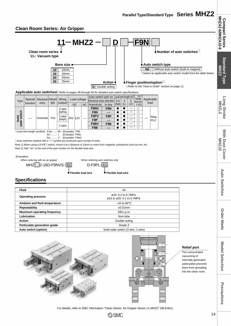
Parallel TypeAir Gripper
Series MHZ
CAT.ES20-140 D
Series upgraded with the addition of new models and expanded size variations
• Long stroke/MHZL2 and compact series/MHZA2-6 introduced• ø6, ø32 and ø40 added to standard MHZ2
• ø6 added to MHZJ2 with dust cover
32, 40
Series Variations
ActionBore size
(mm) Series
WithM5 port
With hose nipple
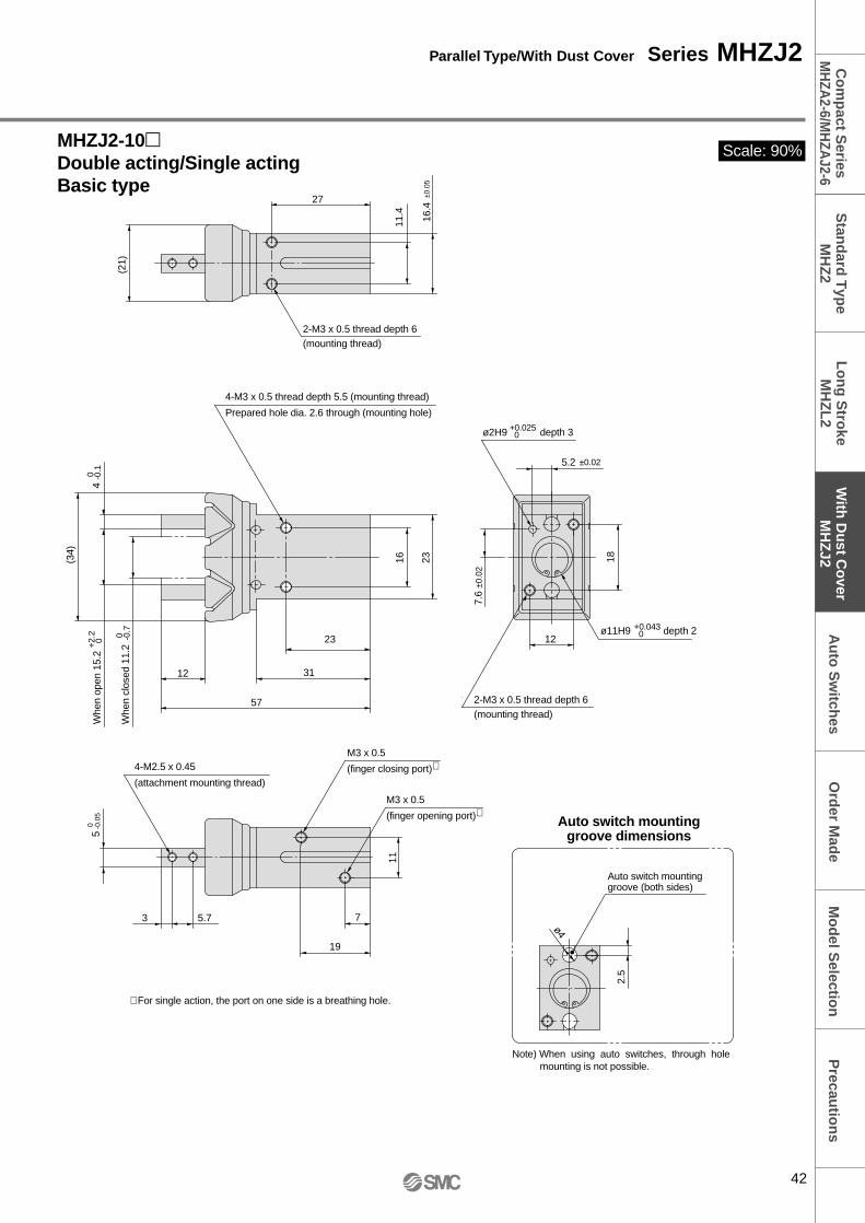
6With dust cover
MHZAJ2-6
Compact series
10, 1620, 25
Long strokeMHZL2
6
10, 1620, 25
Standard
MHZ2
6
10, 1620, 25
With dust cover
MHZJ2
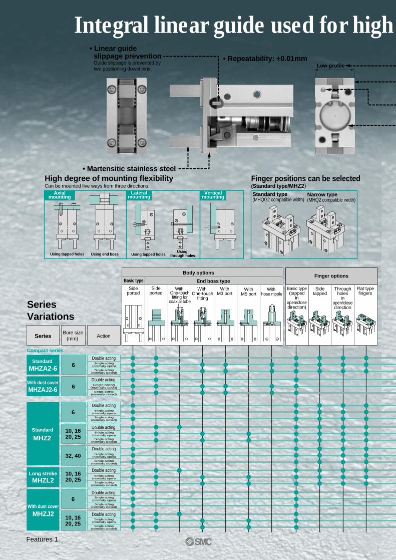
High degree of mounting flexibilityCan be mounted five ways from three directions.
Lateralmounting
Verticalmounting
Axialmounting
Finger positions can be selected(Standard type/MHZ2) Standard type (MHQG2 compatible width)
Narrow type(MHQ2 compatible width)
6Standard
MHZA2-6
Low profile
• Martensitic stainless steel
• Repeatability: ±0.01mm• Linear guide slippage preventionGuide slippage is prevented bytwo positioning dowel pins.
Sideported
Sideported
With One-touchfitting for
coaxial tube
With One-touch
fitting
WithM3 port
Body options
Basic type End boss type
Sidetapped
Basic type(tapped
inopen/close direction)
Throughholes in
open/closedirection
Flat typefingers
Finger options
Using tapped holes Using end boss Using tapped holesUsing
through holes
Double acting
Double acting
Double actingSingle acting
(normally open)
Single acting(normally closed)
Single acting(normally open)
Single acting(normally closed)
Single acting(normally open)
Single acting(normally closed)
Single acting(normally open)
Single acting(normally closed)
Single acting(normally open)
Single acting(normally closed)
Single acting(normally open)
Single acting(normally closed)
Single acting(normally open)
Single acting(normally closed)
Single acting(normally open)
Single acting(normally closed)
Double acting
Double acting
Double acting
Double acting
Double acting
Integral linear guide used for high
Features 1
rigidity and high precision
NewNewAccommodates diverse work piece diameters with a single unit
Long strokes
MHZL2 Nearly double the standard stroke Long strokes are also compact and light weight
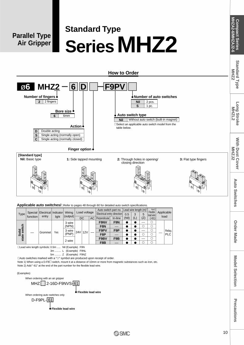
∗ Lead wire length symbols: 0.5m ..... Nil (Example) F9N3m ......... L (Example) F9NL5m ......... Z (Example) F9NZ
∗ Auto switches marked with a "" symbol are produced upon receipt of order.Note 1) When using a D-F8 switch, mount it at a distance of 10mm or more from magnetic substances such as iron, etc.Note 2) Add "-61" at the end of the part number for the flexible lead wire.
––
Type
Applicable auto switches/∗ Refer to pages 48 through 60 for detailed auto switch specifications.
Specialfunction
Indicatorlight
Electricalentry
Wiring(output)
Perpendicular
Load voltageAuto switch part no.
Electrical entry directionLead wire length (m)∗
ApplicableloadIn-line
0.5(Nil)
3(L)
5(Z)DC AC
Grommet Yes
3 wire(NPN)
3 wire(PNP) 24V
F9NVF8N
F9PVF8P
F9BVF8B
F9N––
F9P––
F9B––
Relay,PLC
––
2 wire
12V
––––––
––
So
lidst
ate
switc
h
∗ Select an applicable auto switch model from the table below.
Nil Without auto switch (built-in magnet)∗ Select an auto switch model from the table below.
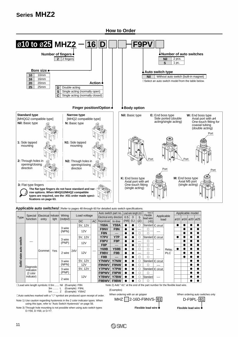
ø10 to ø25 F9PV
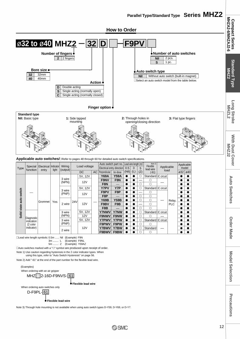
∗ Lead wire length symbols: 0.5m ...... Nil (Example) F9N3m ........ L (Example) F9NL5m ........ Z (Example) Y59AZ
∗ Auto switches marked with a "" symbol are produced upon receipt of order.
––
Diagnosticindication(2 color
indicator)
Type
Applicable auto switches/∗ Refer to pages 48 through 60 for detailed auto switch specifications.
Specialfunction
Electricalentry
Indicatorlight
Wiring(output)
Perpendicular
Load voltageAuto switch part no.Electrical entry direction
Lead wire length (m)∗ Applicable modelApplicable
loadIn-line
0.5(Nil)
3(L)DC AC
Grommet Yes
3 wire(NPN)
3 wire(PNP)
24V
Y69AF9NVF8N
Y7PVF9PVF8P
Y69BF9BVF8B
Y7NWVF9NWVY7PWVF9PWVY7BWVF9BWV
Y59AF9N––
Y7PF9P––
Y59BF9B––
Y7NWF9NWY7PWF9PWY7BWF9BW
––––––
Standard
Standard
Standard
Standard
Standard
Relay,PLC
––2 wire
3 wire(NPN)
3 wire(PNP)
2 wire
5V, 12V
12V
5V, 12V
12V
12V
5V, 12V12V
5V, 12V
12V
IC circuit
––
IC circuit
––
IC circuit––
IC circuit
––
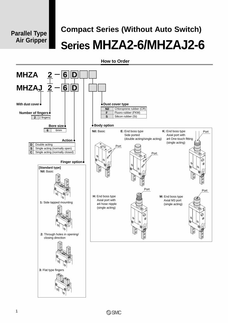
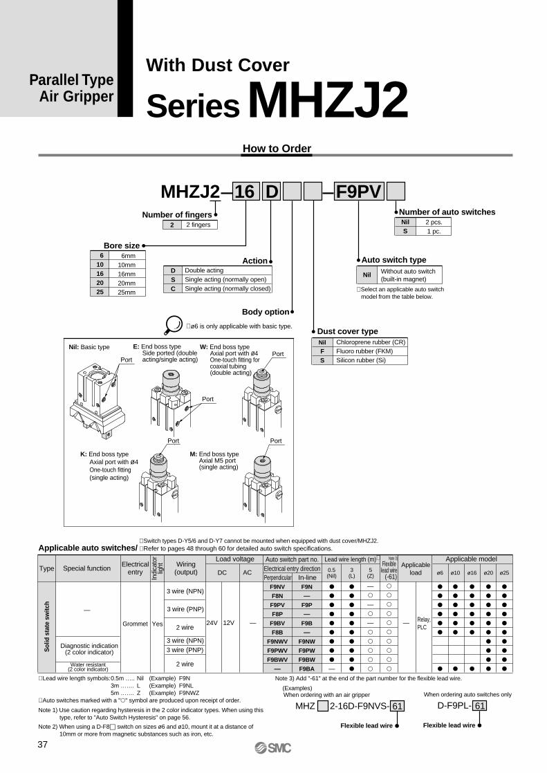
Nil: Basic type
Body option
Port
Port Port
Port
Port
Sol
id s
tate
aut
o sw
itch
5(Z) ø10 ø16 ø20 ø25
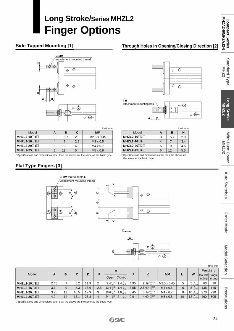
The flat type fingers do not have standard and nar-row options. When MHQG2/MHQ2 compatible types are required, see the -X51 order made speci-fications on page 63.
N2: Through holes in opening/closing direction
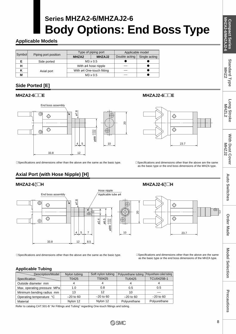
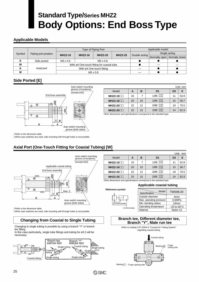
E: End boss typeSide ported (double acting/single acting)
W: End boss typeAxial port with ø4 One-touch fitting for coaxial tubing (double acting)
K: End boss typeAxial port with ø4 One-touch fitting (single acting)
M: End boss typeAxial M5 port(single acting)
Note 1) Use caution regarding hysteresis in the 2 color indicator types. When using this type, refer to "Auto Switch Hysteresis" on page 56.
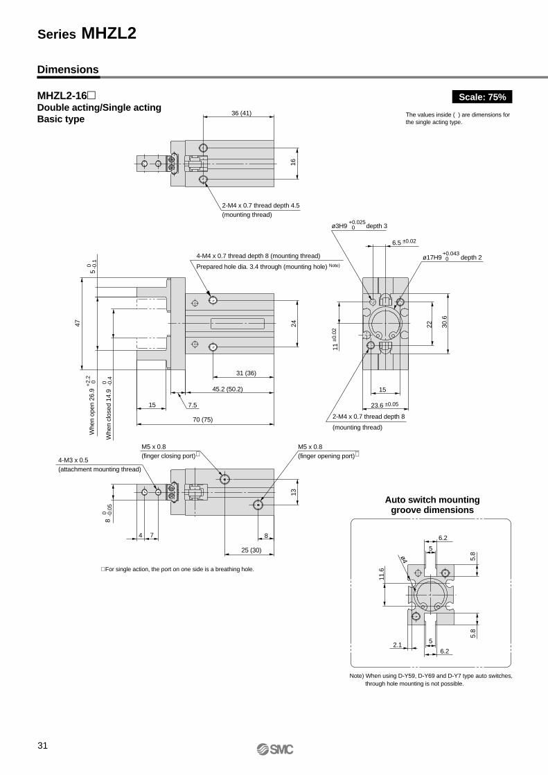
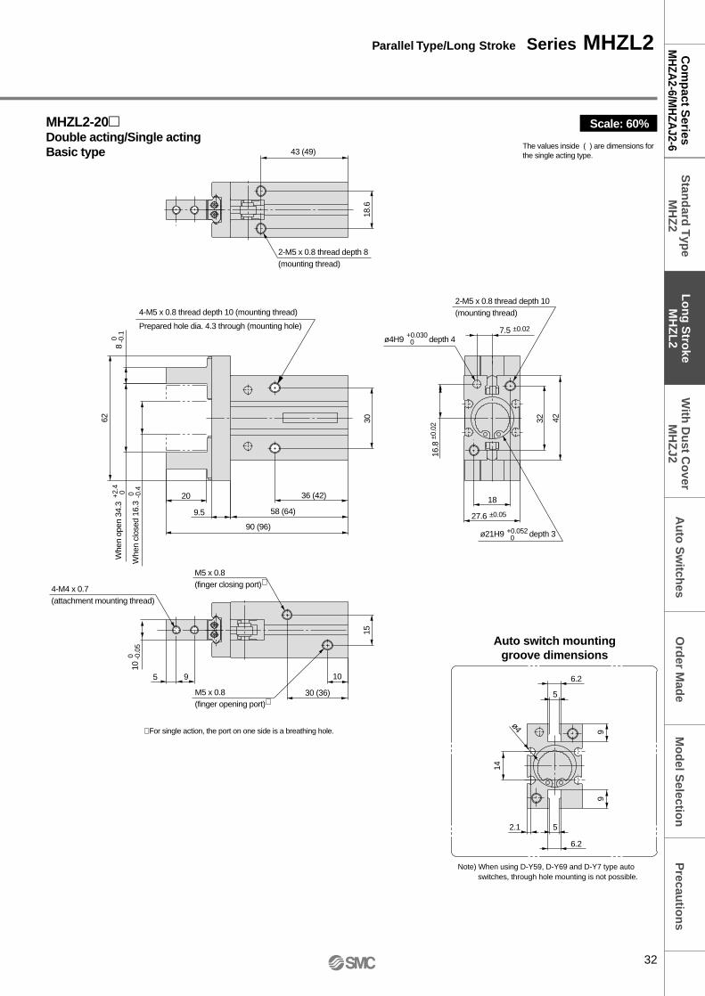
Note 3) Through hole mounting is not possible when using auto switch types D-Y59, D-Y69, or D-Y7.
Note 2) Add "-61" at the end of the part number for the flexible lead wire.
∗ 1) To mount attachments, use M2 hexagon socket head cap screws with ø3.3 top diameter, or JISB1101 type M2 round head screws.∗ 2) Specifications and dimensions other than the above are the same as the basic type (including narrow type).∗ 3) The overall length is the same as the MHQ(G) flat finger type.∗ 4) The values inside ( ) are for the single acting type.
Auto switch mountinggroove (4 locations)(except ø10)
Auto switch mountinggroove (both sides)
B5
AE
Max. 5
øD
1
øD
2
End boss assembly
Applicable coaxial tubing
Auto switch mountinggroove (4 locations)(except ø10)
Auto switch mountinggroove (both sides)
B5
AE
Other dimensions and specifications correspond to the standard type.
Model A
15
20
22
25
B
7
10
12
15
D2
11
15
19
24
E
52.8
58.7
70.5
82.9
D1
12f8
16f8
20f8
25f8
-0.016-0.043
-0.016-0.043
-0.020-0.053
-0.020-0.053
MHZ2-10
MHZ2-16
MHZ2-20
MHZ2-25
Unit: mm
Other dimensions and specifications correspond to the standard type.
Model A
15
20
22
25
B
7
10
12
15
D2
11
15
19
24
E
52.8
58.7
70.5
82.9
D1
12f8
16f8
20f8
25f8
-0.016-0.043
-0.016-0.043
-0.020-0.053
-0.020-0.053
MHZ2-10
MHZ2-16
MHZ2-20
MHZ2-25
Unit: mm
Changing to single tubing is possible by using a branch "Y" or branch tee fitting.In this case particularly, single tube fittings and tubing for ø3.2 will be necessary.
Branch tee, Different diameter tee, Branch "Y", Male run tee
Refer to catalog CAT.E004-A "Coaxial Air Tubing System"regarding coaxial tubing.
Auto switch mountinggroove (4 locations)(except ø10)
Auto switch mountinggroove (both sides)
B5
AE1 (double acting)E2 (single acting)
Max. 5
øD
1
øD
2
End boss assembly
Applicable coaxial tube
Auto switch mountinggroove (4 locations)(except ø10)
Auto switch mountinggroove (both sides)
B5
AE1
Other dimensions and specifications correspond to the standard type.
Model A
15
20
22
25
B
7
10
12
15
E1
52.8
61.4
75.7
86.2
D2
11
15
19
24
E2
62.8
66.4
81.7
96.2
D1
12f8
16f8
20f8
25f8
-0.016-0.043
-0.016-0.043
-0.020-0.053
-0.020-0.053
MHZL2-10
MHZL2-16
MHZL2-20
MHZL2-25
Unit: mm
Other dimensions and specifications correspond to the standard type.
Model A
15
20
22
25
B
7
10
12
15
D2
11
15
19
24
E1
52.8
61.4
75.7
86.2
D1
12f8
16f8
20f8
25f8
-0.016-0.043
-0.016-0.043
-0.020-0.053
-0.020-0.053
MHZL2-10
MHZL2-16
MHZL2-20
MHZL2-25
Unit: mm
Changing to single tubing is possible by using a branch "Y" or branch tee fitting.In this case particularly, single tube fittings and tubing for ø3.2 will be necessary.
Refer to catalog CAT.E004-A "Coaxial Air Tubing System"regarding coaxial tubing.
Auto switch part no.Electrical entry directionPerpendicular In-line
∗ Switch types D-Y5/6 and D-Y7 cannot be mounted when equipped with dust cover/MHZJ2.∗ Refer to pages 48 through 60 for detailed auto switch specifications.
∗ Lead wire length symbols:0.5m ….. Nil (Example) F9N3m ……. L (Example) F9NL5m ……. Z (Example) F9NWZ
∗ Auto switches marked with a "" symbol are produced upon receipt of order.
Port
Port
Port
Port
Port
Nil: Basic type
∗ ø6 is only applicable with basic type.
∗ Select an applicable auto switch model from the table below.
E: End boss typeSide ported (double acting/single acting)
W: End boss typeAxial port with ø4 One-touch fitting for coaxial tubing (double acting)
K: End boss typeAxial port with ø4 One-touch fitting (single acting)
M: End boss typeAxial M5 port (single acting)
Note 3) Add "-61" at the end of the part number for the flexible lead wire.
MHZ 2-16D-F9NVS-
Flexible lead wire
When ordering with an air gripper
61 D-F9PL-
Flexible lead wire
When ordering auto switches only
61Note 1) Use caution regarding hysteresis in the 2 color indicator types. When using this type, refer to "Auto Switch Hysteresis" on page 56.
Note 2) When using a D-F8 switch on sizes ø6 and ø10, mount it at a distance of 10mm or more from magnetic substances such as iron, etc.
Changing to single tubing is possible by using a branch "Y" or branch tee fitting.In this case particularly, single tube fittings and tubing for ø3.2 will be necessary.
Branch tee, Different diameter tee,Branch "Y", Male run tee
Refer to catalog CAT.E004-A "Coaxial Air Tubing System"regarding coaxial tubing.
Precau
tion
sM
od
el Selectio
nC
om
pact S
eriesM
HZA
2-6/MH
ZAJ2-6
Stan
dard
Typ
eM
HZ
2A
uto
Sw
itches
Lo
ng
Stro
keM
HZ
L2
With
Du
st Co
verM
HZ
J2O
rder M
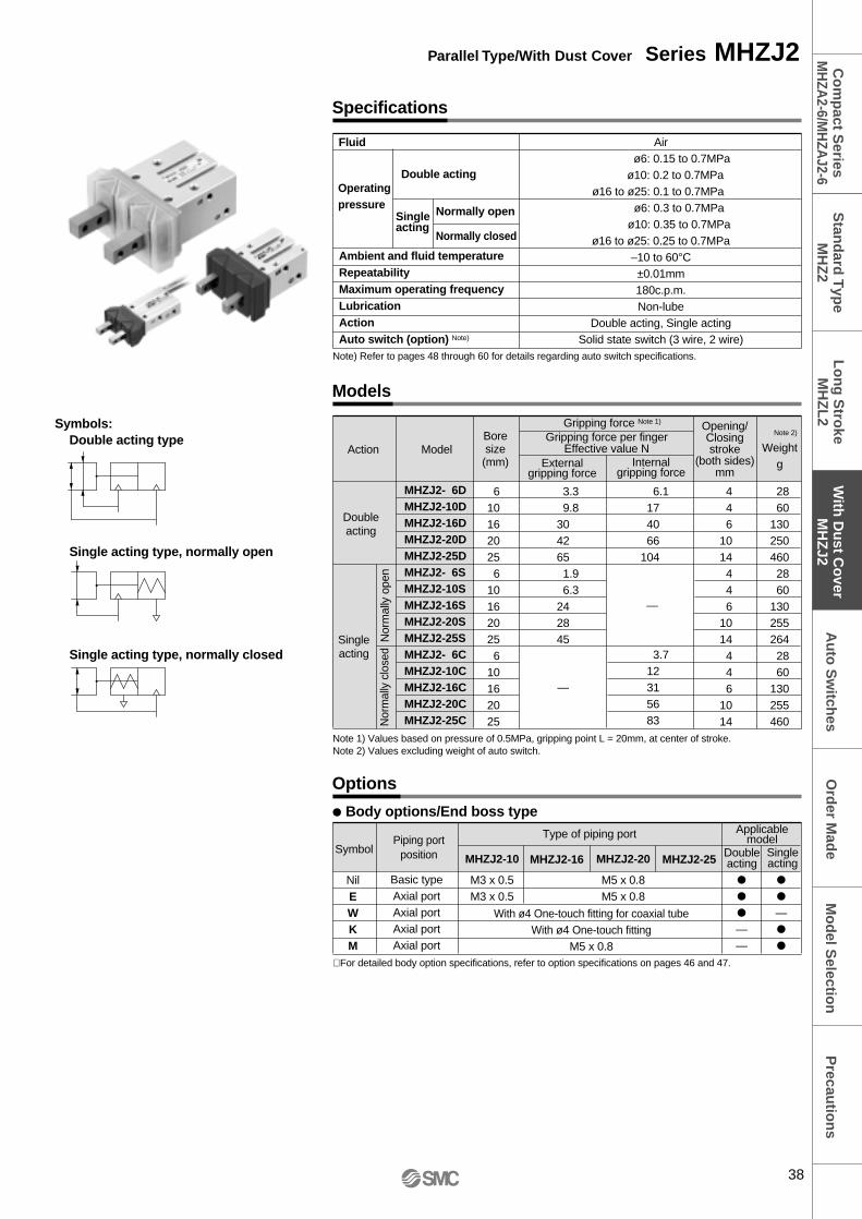
ade
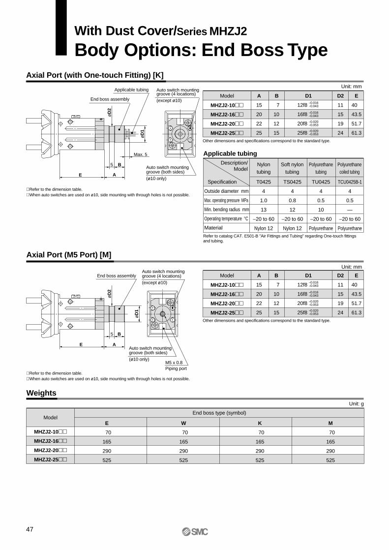
With Dust Cover/Series MHZJ2
Body Options: End Boss Type
46
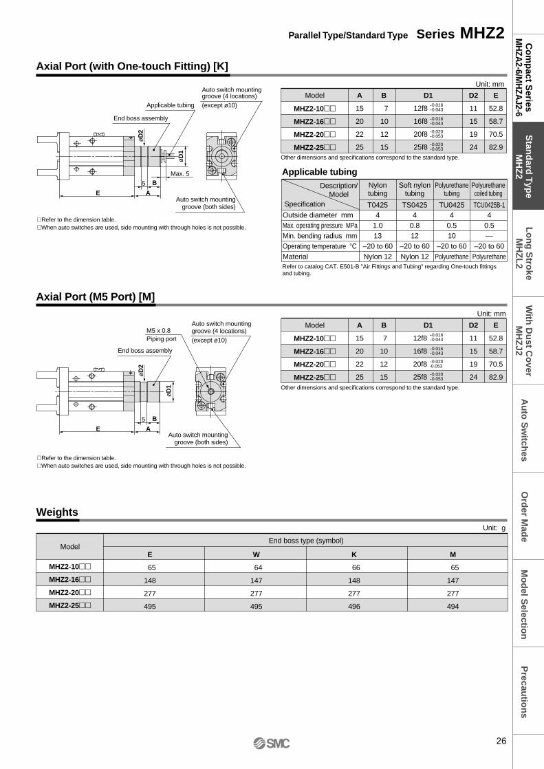
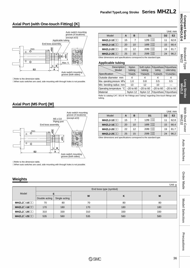
Axial Port (M5 Port) [M]
∗ Refer to the dimension table.∗ When auto switches are used on ø10, side mounting with through holes is not possible.
Auto switch mountinggroove (both sides)(ø10 only)
E A
Auto switch mountinggroove (4 locations)(except ø10)
End boss assembly
5 B
øD
2
øD
1
M5 x 0.8Piping port
ModelW
70
165
290
525
K
70
165
290
525
End boss type (symbol)
Unit: g
M
70
165
290
525
E
70
165
290
525
MHZJ2-10
MHZJ2-16
MHZJ2-20
MHZJ2-25
Weights
Axial Port (with One-touch Fitting) [K]
∗ Refer to the dimension table.∗ When auto switches are used on ø10, side mounting with through holes is not possible.
E A
B
Max. 5
End boss assembly
Applicable tubing Auto switch mountinggroove (4 locations)(except ø10)
Auto switch mountinggroove (both sides)(ø10 only)
5
øD
2
øD
1
Applicable tubingDescription/
ModelNylontubing
T0425
4
1.0
13
–20 to 60
Nylon 12
TS0425
4
0.8
12
–20 to 60
Nylon 12
TU0425
4
0.5
10
–20 to 60
Polyurethane
TCU0425B-1
4
0.5
—
–20 to 60
Polyurethane
Soft nylontubing
Polyurethanecoiled tubing
Polyurethanetubing
Specification
Outside diameter mm
Max. operating pressure MPa
Min. bending radius mm
Operating temperature °C
Material
Other dimensions and specifications correspond to the standard type.
Model A
15
20
22
25
B
7
10
12
15
D2
11
15
19
24
E
40
43.5
51.7
61.3
D1
12f8
16f8
20f8
25f8
-0.016-0.043
-0.016-0.043
-0.020-0.053
-0.020-0.053
MHZJ2-10
MHZJ2-16
MHZJ2-20
MHZJ2-25
Unit: mm
Other dimensions and specifications correspond to the standard type.
Model A
15
20
22
25
B
7
10
12
15
D2
11
15
19
24
E
40
43.5
51.7
61.3
D1
12f8
16f8
20f8
25f8
-0.016-0.043
-0.016-0.043
-0.020-0.053
-0.020-0.053
MHZJ2-10
MHZJ2-16
MHZJ2-20
MHZJ2-25
Unit: mm
Refer to catalog CAT. E501-B "Air Fittings and Tubing" regarding One-touch fittings and tubing.
With Dust Cover/Series MHZJ2
Body Options: End Boss Type
47
Precau
tion
sM
od
el Selectio
nC
om
pact S
eriesM
HZA
2-6/MH
ZAJ2-6
Stan
dard
Typ
eM
HZ
2A
uto
Sw
itches
Lo
ng
Stro
keM
HZ
L2
With
Du
st Co
verM
HZ
J2O
rder M
ade
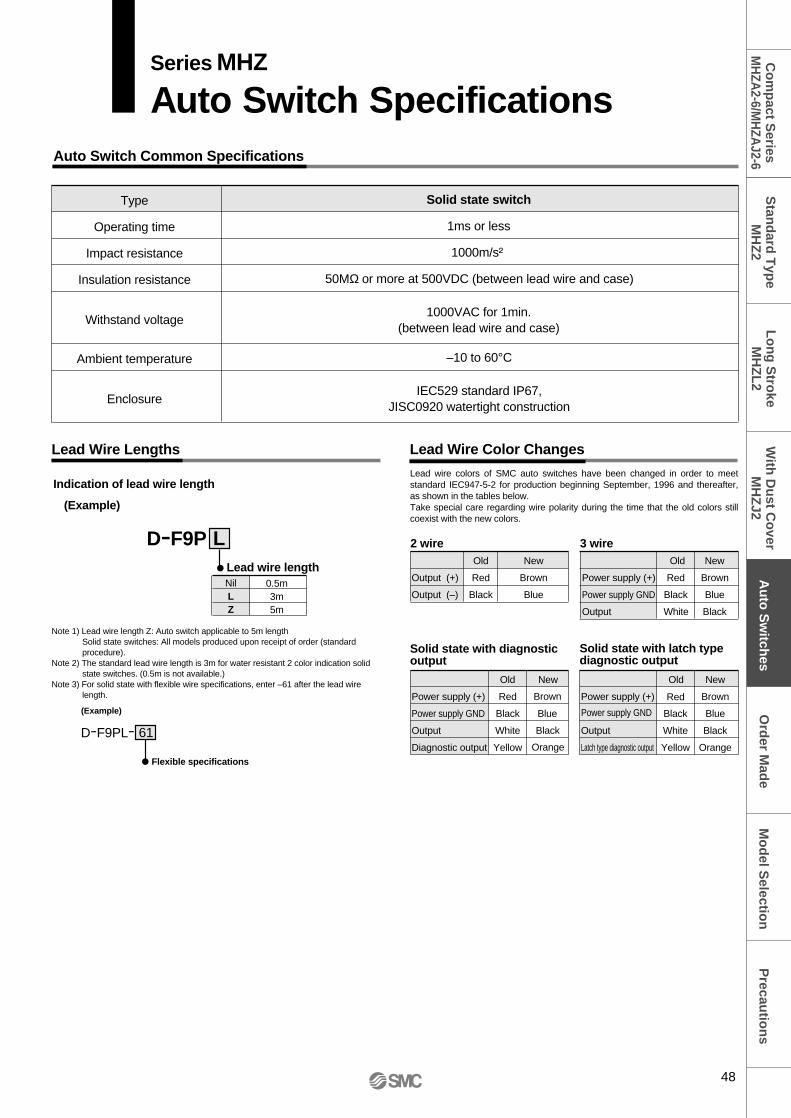
Auto Switch Common Specifications
Lead Wire Lengths
Type
Operating time
Impact resistance
Insulation resistance
Withstand voltage
Ambient temperature
Enclosure
Solid state switch
1ms or less
1000m/s²
1000VAC for 1min.(between lead wire and case)
50MΩ or more at 500VDC (between lead wire and case)
–10 to 60°C
IEC529 standard IP67,JISC0920 watertight construction
Lead Wire Color Changes
D-F9P Lead wire length
Indication of lead wire length
(Example)
NilLZ
0.5m3m5m
L
D-F9PL-
Flexible specifications
(Example)
61
Output (+)
Output (–)
Red
Old
Black
Brown
New
Blue
2 wire 3 wire
Power supply (+)
Power supply GND
Red
Old
Black
Brown
New
Blue
Output White Black
Power supply (+)
Power supply GND
Red
Old
Black
Brown
New
Blue
Output White Black
Diagnostic output Yellow Orange
Power supply (+)
Power supply GND
Red
Old
Black
Brown
New
Blue
Output White Black
Latch type diagnostic output Yellow Orange
Lead wire colors of SMC auto switches have been changed in order to meet standard IEC947-5-2 for production beginning September, 1996 and thereafter, as shown in the tables below.Take special care regarding wire polarity during the time that the old colors still coexist with the new colors.
Note 1) Lead wire length Z: Auto switch applicable to 5m lengthSolid state switches: All models produced upon receipt of order (standard procedure).
Note 2) The standard lead wire length is 3m for water resistant 2 color indication solid state switches. (0.5m is not available.)
Note 3) For solid state with flexible wire specifications, enter –61 after the lead wire length.
Solid state with latch type diagnostic output
Solid state with diagnostic output
Series MHZ
Auto Switch Specifications
48
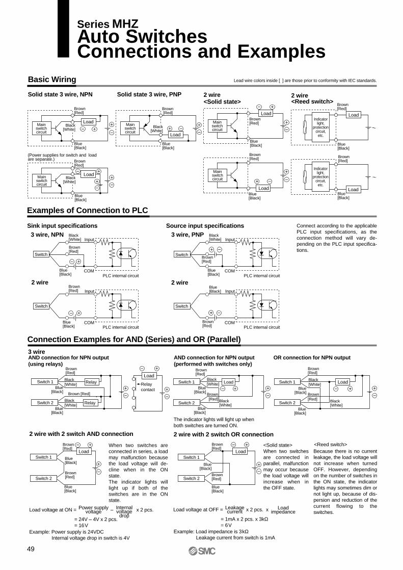
Basic Wiring
Solid state 3 wire, NPN
Sink input specifications
2 wire
Source input specifications
2 wire with 2 switch AND connection 2 wire with 2 switch OR connection
2 wire 2 wire
Solid state 3 wire, PNP
Example: Power supply is 24VDC Internal voltage drop in switch is 4V
Example: Load impedance is 3kΩLeakage current from switch is 1mA
(Power supplies for switch and load are separate.)
Connection Examples for AND (Series) and OR (Parallel)
Examples of Connection to PLC
Connect according to the applicable PLC input specifications, as the connection method will vary de-pending on the PLC input specifica-tions.
When two switches are connected in series, a load may malfunction because the load voltage will de-cline when in the ON state.The indicator lights will light up if both of the switches are in the ON state.
<Solid state>When two switches are connected in parallel, malfunction may occur because the load voltage will increase when in the OFF state.
Blue[Black]
Mainswitchcircuit
Load
Brown [Red]
Black[White]
Mainswitchcircuit
Brown[Red]
Load
Blue[Black]
Black[White]
Mainswitchcircuit
LoadBlue[Black]
Brown[Red]
Mainswitchcircuit
Load
Blue[Black]
Brown[Red]
Mainswitchcircuit
Load
Brown[Red]
Blue[Black]
Black[White]
PLC internal circuitCOM
Switch
InputBlack[White]
Brown[Red]
Blue[Black]
PLC internal circuitCOM
Switch
InputBrown[Red]
Blue[Black] PLC internal circuit
Switch
Input
COM
Blue[Black]
Brown[Red]
PLC internal circuitCOM
Switch
InputBlack[White]
Brown[Red]
Blue[Black]
Switch 1
Switch 2
Load
Blue[Black]
Brown[Red]
Blue[Black]
Brown[Red]
Switch 1
Switch 2
Load
Brown[Red]
Blue[Black]
Brown[Red]
Blue[Black]
3 wireOR connection for NPN output
Switch 1
Switch 2
LoadSwitch 1
Brown[Red]
Switch 2
Black[White]
Blue[Black]
Relay
RelayBlack[White]
Load
Relaycontact
AND connection for NPN output(using relays)
Switch 1
Brown[Red]
Switch 2
Load
Brown[Red]
AND connection for NPN output(performed with switches only)
The indicator lights will light up when both switches are turned ON.
<Reed switch>
2 wire
Indicatorlight,
protectioncircuit,
etc.
Brown[Red]
Blue[Black]
Load
<Reed switch>
Brown[Red]
Blue[Black]
Load
<Solid state>
3 wire, NPN 3 wire, PNP
Brown [Red]
Blue[Black]
Blue[Black]
Black[White]
Black[White]
Blue[Black]
Brown[Red]
Blue[Black]
Black[White]
Blue[Black]
Black[White]
Brown[Red]
Because there is no current leakage, the load voltage will not increase when turned OFF. However, depending on the number of switches in the ON state, the indicator lights may sometimes dim or not light up, because of dis-persion and reduction of the current flowing to the switches.
Indicatorlight,
protectioncircuit,
etc.
Load voltage at ON = – x 2 pcs.
= 24V – 4V x 2 pcs. = 16V
Power supply voltage
Internal voltage
drop
Leakagecurrent
LoadimpedanceLoad voltage at OFF = x 2 pcs. x
= 1mA x 2 pcs. x 3kΩ= 6V
Lead wire colors inside [ ] are those prior to conformity with IEC standards.
Series MHZAuto Switches Connections and Examples
49
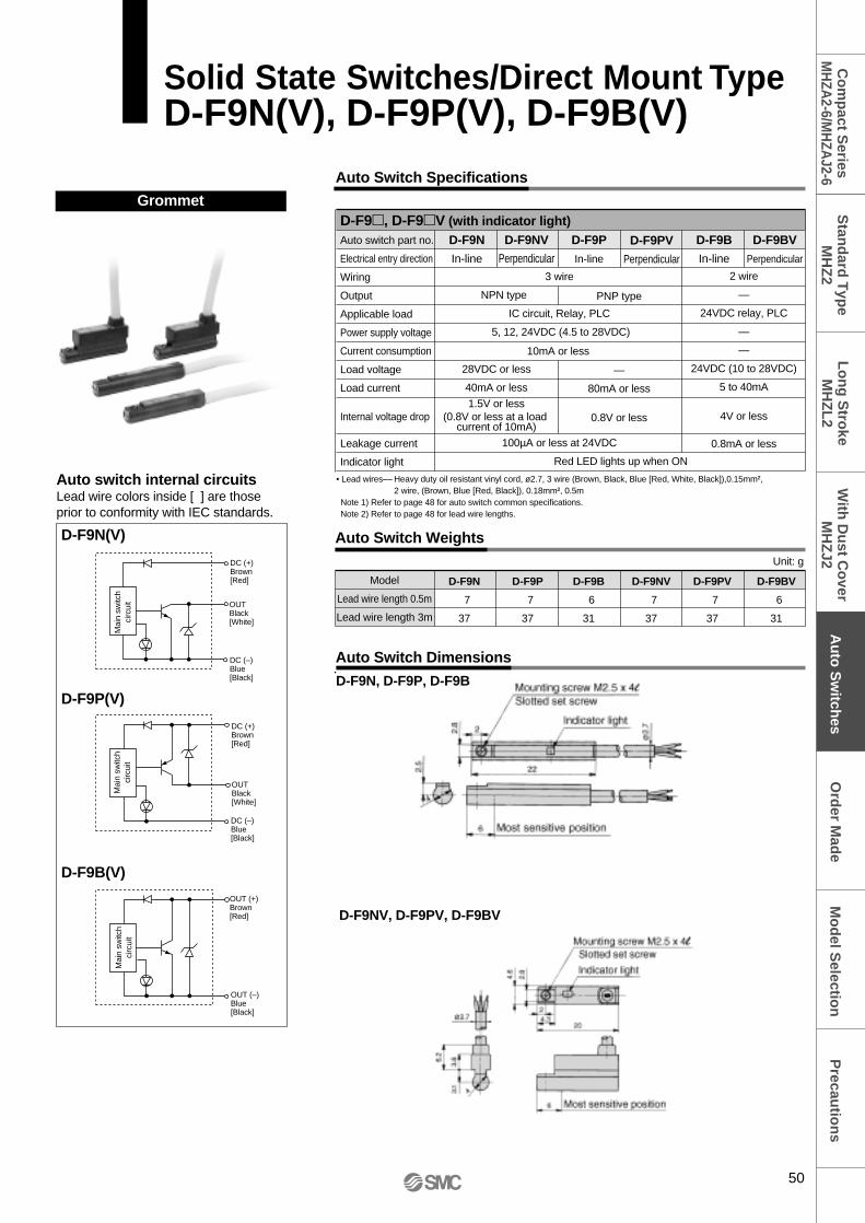
D-F9N(V)
D-F9B(V)
D-F9P(V)
Grommet
Auto Switch Specifications
Auto Switch Weights
Auto Switch Dimensions
Model
Lead wire length 0.5m
Lead wire length 3m
D-F9N
7
37
D-F9P
7
37
D-F9B
6
31
D-F9NV
7
37
D-F9PV
7
37
D-F9BV
6
31
D-F9NV
Perpendicular
D-F9BV
Perpendicular
D-F9PV
Perpendicular2 wire
—
24VDC relay, PLC
—
—
24VDC (10 to 28VDC)
5 to 40mA
4V or less
0.8mA or less
PNP type
—
80mA or less
0.8V or less
D-F9N, D-F9P, D-F9B
D-F9NV, D-F9PV, D-F9BV
Unit: g
OUTBlack[White]
DC (+)Brown[Red]
DC (–)Blue[Black]
Mai
n sw
itch
circ
uit
OUTBlack [White]
DC (+)Brown [Red]
DC (–)Blue[Black]
OUT (+)Brown[Red]
Mai
n sw
itch
circ
uit
OUT (–)Blue[Black]
Mai
n sw
itch
circ
uit
D-F9, D-F9V (with indicator light)Auto switch part no.
Electrical entry direction
Wiring
Output
Applicable load
Power supply voltage
Current consumption
Load voltage
Load current
Internal voltage drop
Leakage current
Indicator light
3 wire
NPN type
IC circuit, Relay, PLC
5, 12, 24VDC (4.5 to 28VDC)
100µA or less at 24VDC
Red LED lights up when ON
D-F9N
In-line
28VDC or less
40mA or less
1.5V or less(0.8V or less at a load
current of 10mA)
D-F9P
In-line
D-F9B
In-line
• Lead wires–– Heavy duty oil resistant vinyl cord, ø2.7, 3 wire (Brown, Black, Blue [Red, White, Black]),0.15mm²,2 wire, (Brown, Blue [Red, Black]), 0.18mm², 0.5m
Note 1) Refer to page 48 for auto switch common specifications.Note 2) Refer to page 48 for lead wire lengths.
Auto switch internal circuitsLead wire colors inside [ ] are those prior to conformity with IEC standards.
10mA or less
50
Solid State Switches/Direct Mount TypeD-F9N(V), D-F9P(V), D-F9B(V)
Precau
tion
sM
od
el Selectio
nC
om
pact S
eriesM
HZA
2-6/MH
ZAJ2-6
Stan
dard
Typ
eM
HZ
2A
uto
Sw
itches
Lo
ng
Stro
keM
HZ
L2
With
Du
st Co
verM
HZ
J2O
rder M
ade
D-F8N
D-F8B
D-F8P
Auto Switch Specifications
Auto Switch Weights
Auto Switch Dimensions
Auto switch part no.
Electrical entry direction
Wiring
Output
Applicable load
Power supply voltage
Current consumption
Load voltage
Load current
Internal voltage drop
Leakage current
Indicator light
Model
Lead wire length 0.5m
Lead wire length 3m
7
32
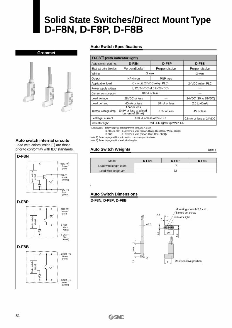
D-F8N D-F8P D-F8B
D-F8N
Perpendicular
NPN type
28VDC or less
40mA or less
D-F8B
Perpendicular
2 wire
—
24VDC relay, PLC
—
—
24VDC (10 to 28VDC)
2.5 to 40mA
4V or less
0.8mA or less at 24VDC
D-F8P
Perpendicular
PNP type
—
80mA or less
0.8V or less
• Lead wires––Heavy duty oil resistant vinyl cord, ø2.7, 0.5mD-F8N, D-F8P 0.15mm² x 3 wire (Brown, Black, Blue [Red, White, Black])D-F8B 0.18mm² x 2 wire (Brown, Blue [Red, Black])
Note 1) Refer to page 48 for auto switch common specifications.Note 2) Refer to page 48 for lead wire lengths.
D-F8N, D-F8P, D-F8B
1.5V or less(0.8V or less at a load
current of 10mA)
Red LED lights up when ON
100µA or less at 24VDC
OUTBlack[White]
DC (+) Brown[Red]
DC (–) Blue[Black]
Mai
n sw
itch
circ
uit
DC (+)Brown[Red]
DC (–) Blue[Black]
OUTBlack[White]
Mai
n sw
itch
circ
uit
Mai
n sw
itch
circ
uit
OUT (+) Brown[Red]
OUT (–)Blue[Black]
Unit: g
3 wire
IC circuit, 24VDC relay, PLC
5, 12, 24VDC (4.5 to 28VDC)
10mA or less
Mounting screw M2.5 x 4lSlotted set screw
Indicator light
Most sensitive position
10
4.62.
8
2
4.3
ø2.7
4
3.1
10.9
3
8
GrommetD-F8 (with indicator light)
Auto switch internal circuitsLead wire colors inside [ ] are those prior to conformity with IEC standards.
51
Solid State Switches/Direct Mount TypeD-F8N, D-F8P, D-F8B
Precau
tion
sM
od
el Selectio
nC
om
pact S
eriesM
HZA
2-6/MH
ZAJ2-6
Stan
dard
Typ
eM
HZ
2A
uto
Sw
itches
Lo
ng
Stro
keM
HZ
L2
With
Du
st Co
verM
HZ
J2O
rder M
ade
Grommet
Auto Switch Weights
Auto Switch Dimensions
Model
Lead wire length 0.5m
Lead wire length 3m
D-F9NW
7
34
D-F9NWV
7
34
D-F9PW
7
34
D-F9PWV
7
34
D-F9BW
7
32
D-F9BWV
7
32
D-F9NW(V)
D-F9BW(V)
Indicator light/Display method
D-F9PW(V)
Auto Switch Specifications
Unit: g
D-F9W, D-F9 WV (with indicator light)D-F9NWV
Perpendicular
D-F9PW
In-line
D-F9PWV
Perpendicular
D-F9BW
In-line
D-F9BWV
Perpendicular
2 wire
––
24VDC relay, PLC
––
––
24VDC (10 to 28VDC)
5 to 40mA
4V or less
0.8mA or less
––
80mA or less
0.8V or less
PNP type
D-F9NW, D-F9PW, D-F9BW
D-F9NWV, D-F9PWV, D-F9BWV
Auto switch part no.
Electrical entry direction
Wiring
Output
Applicable load
Power supply voltage
Current consumption
Load voltage
Load current
Internal voltage drop
Leakage current
Indicator light
3 wire
IC circuit, Relay IC, PLC
5, 12, 24VDC (4.5 to 28VDC)
10mA or less
100µA or less at 24VDC
OUTBlack[White]
DC (+)Brown[Red]
DC (–)Blue[Black]
Mai
n sw
itch
circ
uit
OUTBlack [White]
DC (+)Brown [Red]
DC (–)Blue[Black]
OUT (+)Brown[Red]
Mai
n sw
itch
circ
uit
OUT (–)Blue[Black]
Mai
n sw
itch
circ
uit
D-F9NW
In-line
NPN type
28VDC or less
0.4mA or less1.5V or less
(0.8V or less at a load current of 10mA)
Actuated position ...................... Red LED lights upOptimum operating position ....... Green LED lights up
• Lead wires––Heavy duty oil resistant vinyl cord, ø2.7, 3 wire (Brown, Black, Blue [Red, White, Black]), 0.15mm², 2 wire (Brown, Blue [Red, Black]), 0.18mm², 0.5m
Note 1) Refer to page 48 for auto switch common specifications.Note 2) Refer to page 48 for lead wire lengths.
Auto switch internal circuitsLead wire colors inside [ ] are those prior to conformity with IEC standards.
2 Color Indication Solid State SwitchesDirect Mount TypeD-F9NW(V), DY-F9PW(V), D-F9BW(V)
52
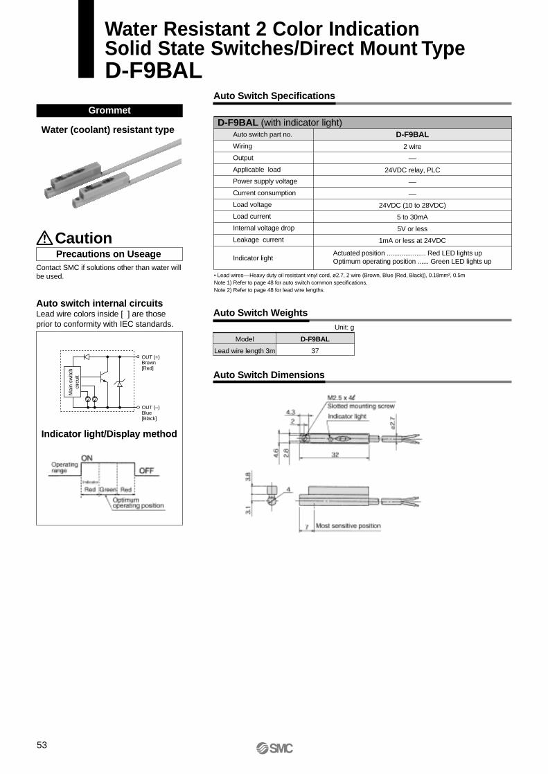
Water (coolant) resistant type
Indicator light/Display method
Grommet
Precautions on Useage
Auto Switch Dimensions
Auto Switch Weights
Model
Lead wire length 3m
D-F9BAL
37
D-F9BAL
2 wire
––
24VDC relay, PLC
––
––
24VDC (10 to 28VDC)
5 to 30mA
5V or less
1mA or less at 24VDC
Actuated position ..................... Red LED lights upOptimum operating position ...... Green LED lights up
Auto Switch Specifications
Unit: g
• Lead wires––Heavy duty oil resistant vinyl cord, ø2.7, 2 wire (Brown, Blue [Red, Black]), 0.18mm², 0.5mNote 1) Refer to page 48 for auto switch common specifications.Note 2) Refer to page 48 for lead wire lengths.
D-F9BAL (with indicator light)
Caution
Contact SMC if solutions other than water will be used.
Auto switch part no.
Wiring
Output
Applicable load
Power supply voltage
Current consumption
Load voltage
Load current
Internal voltage drop
Leakage current
Indicator light
OUT (+)Brown[Red]
OUT (–)Blue[Black]
Mai
n sw
itch
circ
uit
Auto switch internal circuitsLead wire colors inside [ ] are those prior to conformity with IEC standards.
53
Water Resistant 2 Color IndicationSolid State Switches/Direct Mount TypeD-F9BAL
Precau
tion
sM
od
el Selectio
nC
om
pact S
eriesM
HZA
2-6/MH
ZAJ2-6
Stan
dard
Typ
eM
HZ
2A
uto
Sw
itches
Lo
ng
Stro
keM
HZ
L2
With
Du
st Co
verM
HZ
J2O
rder M
ade
Auto Switch Dimensions
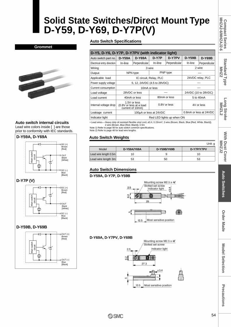
D-Y59A, D-Y69A
D-Y59B, D-Y69B
D-Y7P (V)
Auto Switch Specifications
D-Y5, D-Y6, D-Y7P, D-Y7PV (with indicator light)Auto switch part no.
Electrical entry direction
Wiring
Output
Applicable load
Power supply voltage
Current consumption
Load voltage
Load current
Internal voltage drop
Leakage current
Indicator light
D-Y59A
In-line
D-Y69A
Perpendicular
D-Y69B
Perpendicular
D-Y7PV
Perpendicular
D-Y59B
In-line
2 wire
––
24VDC relay, PLC
––
––
24VDC (10 to 28VDC)
5 to 40mA
4V or less
0.8mA or less at 24VDC
D-Y7P
In-line
10mA or less
Grommet
Auto Switch Weights
Model
Lead wire length 0.5m
Lead wire length 3m
D-Y59A/Y69A
10
53
D-Y59B/Y69B
9
50
D-Y7P/Y7PV
10
53
Unit: gDC (+)Brown[Red]
DC (–)Blue[Black]
OUTBlack[White]
Mai
n sw
itch
circ
uit
Mai
n sw
itch
circ
uit
OUT (+)Brown[Red]
OUT (–)Blue[Black]
DC (+)Brown[Red]
DC (–)Blue[Black]
OUTBlack[White]
Mai
n sw
itch
circ
uit
Auto switch internal circuitsLead wire colors inside [ ] are those prior to conformity with IEC standards.
3 wire
IC circuit, Relay, PLC
5, 12, 24VDC (4.5 to 28VDC)
100µA or less at 24VDC
Red LED lights up when ON
NPN type
28VDC or less
40mA or less
1.5V or less
PNP type
––
80mA or less
0.8V or less
• Lead wires––Heavy duty oil resistant flexible vinyl cord, ø3.4, 0.15mm², 3 wire (Brown, Black, Blue [Red, White, Black]), 2 wire (Brown, Blue [Red, Black]), 0.5m
Note 1) Refer to page 48 for auto switch common specifications.Note 2) Refer to page 48 for lead wire lengths.
(0.8V or less at a load current of 10mA)
D-Y69A, D-Y7PV, D-Y69B
D-Y59A, D-Y7P, D-Y59B
Solid State Switches/Direct Mount TypeD-Y59, D-Y69, D-Y7P(V)
54
D-Y7NW(V)
D-Y7BW(V)
Indicator light/Display method
D-Y7PW(V)
Grommet
Auto Switch Dimensions
D-Y7W
D-Y7WV
Auto Switch Specifications
D-Y7W, D-Y7WV (with indicator light)Auto switch part no.
Electrical entry direction
Wiring
Output
Applicable load
Power supply voltage
Current consumption
Load voltage
Load current
Internal voltage drop
Leakage current
Indicator light
3 wire
IC circuit, Relay, PLC
5, 12, 24VDC (4.5 to 28VDC)
10mA or less
100µA or less at 24VDC
D-Y7NWV
Perpendicular
D-Y7BWV
Perpendicular
D-Y7PWV
Perpendicular
2 wire
––
24VDC relay, PLC
––
––
24VDC (10 to 28VDC)
5 to 40mA
4V or less
0.8mA or less at 24VDC
PNP type
–
80mA or less
0.8V or less
Auto Switch Weights
Model
Lead wire length 0.5m
Lead wire length 3m
D-Y7PW
11
54
D-Y7BW
11
54
D-Y7NW
11
54
Unit: gOUTBlack[White]
DC (+)Brown[Red]
DC (–)Blue[Black]
Mai
n sw
itch
circ
uit
OUTBlack [White]
DC (+)Brown [Red]
DC (–)Blue[Black]
OUT (+)Brown[Red]
Mai
n sw
itch
circ
uit
OUT (–)Blue[Black]
Mai
n sw
itch
circ
uit
The optimum operating position can be determined by the color of the light. (Red→Green←Red)
D-Y7NW
In-line
NPN type
28VDC or less
40mA or less
1.5V or less(0.8V or less at a load
current of 10mA)
D-Y7PW
In-line
Actuated position .................... Red LED lights upOptimum operating position ..... Green LED lights up
D-Y7BW
In-line
• Lead wires––Heavy duty oil resistant flexible vinyl cord, ø3.4, 0.15mm², 3 wire (Brown, Black, Blue [Red, White, Black]),2 wire (Brown, Blue [Red, Black]), 0.5m
Note 1) Refer to page 48 for auto switch common specifications.Note 2) Refer to page 48 for lead wire lengths.
Auto switch internal circuitsLead wire colors inside [ ] are those prior to conformity with IEC standards.
55
2 Color Indication Solid StateSwitches Direct Mount TypeD-Y7NW(V), D-Y7PW(V), D-Y7BW(V)
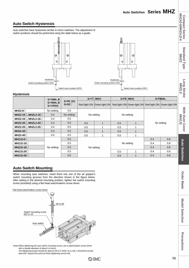
Auto Switch Hysteresis
Auto Switch Mounting
Auto switches have hysteresis similar to micro switches. The adjustment of switch positions should be performed using the table below as a guide.
Red light ON Green light ON Red light ON Green light ON Red light ON Green light ON
D-F9W(V) D-F9BAL
Switch return position (OFF)
Hysteresis
Switch actuating position (ON)
Switch return position (OFF)
Flat head watchmakers screw driver
Auto switch
ø5 to ø6
Switch mounting screwM2.5 x 4l
Hysteresis
When mounting auto switches, insert them into one of the air gripper's switch mounting grooves from the direction shown in the figure below. After setting in the desired mounting position, tighten the switch mounting screw (included) using a flat head watchmakers screw driver.
Note) When tightening the auto switch mounting screw, use a watchmakers screw driver with a handle diameter of about 5 to 6mm.The tightening torque should be about 0.05 to 0.1N⋅m. As a rule, it should be turned about 90° beyond the point at which tightening can be felt.
56
Auto Switches Series MHZP
recautio
ns
Mo
del S
election
Co
mp
act Series
MH
ZA2-6/M
HZA
J2-6S
tand
ard T
ype
MH
Z2
Au
to S
witch
esL
on
g S
troke
MH
ZL
2W
ith D
ust C
over
MH
ZJ2
Ord
er Mad
e
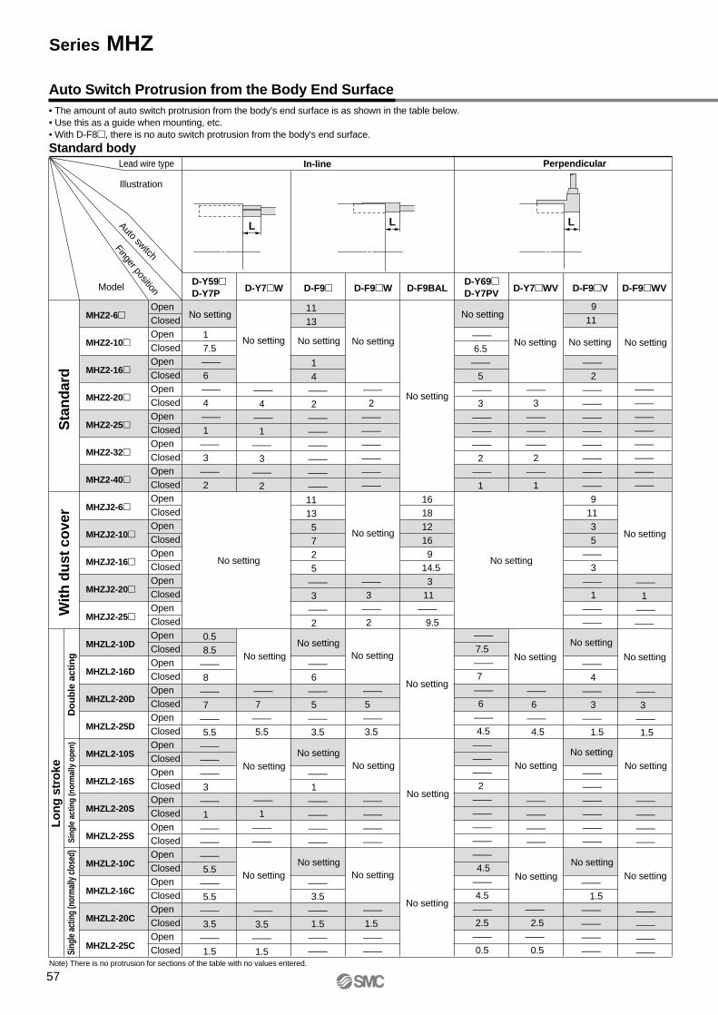
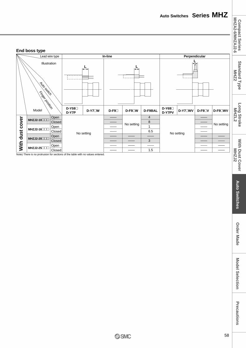
Auto Switch Protrusion from the Body End Surface• The amount of auto switch protrusion from the body's end surface is as shown in the table below.• Use this as a guide when mounting, etc.• With D-F8, there is no auto switch protrusion from the body's end surface.
Note) There is no protrusion for sections of the table with no values entered.
End boss type
L L
L
Auto switch
Finger position
With
dus
t cov
er
58
Auto Switches Series MHZP
recautio
ns
Mo
del S
election
Co
mp
act Series
MH
ZA2-6/M
HZA
J2-6S
tand
ard T
ype
MH
Z2
Au
to S
witch
esL
on
g S
troke
MH
ZL
2W
ith D
ust C
over
MH
ZJ2
Ord
er Mad
e
Detection example
Detectionposition
Operation ofauto switch
How to determinethe auto switch
installation position
Capable withone auto switch
Det
ectio
nco
mb
inat
ion
s
Two auto switchesrequired
1. To confirm that fingershave returned
2. To confirm that workpiece has been gripped
3. To confirm that work piecehas not been gripped
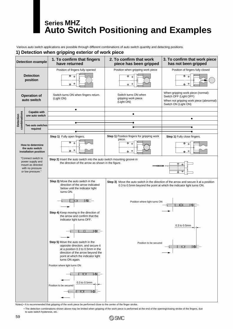
1) Detection when gripping exterior of work piece
Position when gripping work piece Position of fingers fully closed
Switch turns ON when fingers return.(Light ON)
Switch turns ON whengripping work piece.(Light ON)
When gripping work piece (normal):Switch OFF (Light OFF)
When not gripping work piece (abnormal):Switch ON (Light ON)
•
•
•
•
•
•
•
••
Step 1) Fully open fingers. Step 1) Fully close fingers.
Position where light turns ON
Position to be secured
Position of fingers fully opened
0.3 to 0.5mm
0.3 to 0.5mm
Various auto switch applications are possible through different combinations of auto switch quantity and detecting positions.
"Connect switch to power supply and mount as directed with no pressure or low pressure."
Step 2) Insert the auto switch into the auto switch mounting groove in the direction of the arrow as shown in the figure.
Step 1) Position fingers for gripping work piece.
Step 3) Move the auto switch in the direction of the arrow indicated below until the indicator light turns ON.
Step 4) Keep moving in the direction of the arrow and confirm that the indicator light turns OFF.
Step 5) Move the auto switch in the opposite direction, and secure it at a position 0.3 to 0.5mm in the direction of the arrow beyond the point at which the indicator light turns ON again.
Notes) • It is recommended that gripping of the work piece be performed close to the center of the finger stroke.
• The detection combinations shown above may be limited when gripping of the work piece is performed at the end of the opening/closing stroke of the fingers, due to auto switch hysteresis, etc.
Step 3) Move the auto switch in the direction of the arrow and secure it at a position 0.3 to 0.5mm beyond the point at which the indicator light turns ON.
Position to be secured
Position where light turns ON
Series MHZAuto Switch Positioning and Examples
59
Precau
tion
sM
od
el Selectio
nC
om
pact S
eriesM
HZA
2-6/MH
ZAJ2-6
Stan
dard
Typ
eM
HZ
2A
uto
Sw
itches
Lo
ng
Stro
keM
HZ
L2
With
Du
st Co
verM
HZ
J2O
rder M
ade
Detection example
Detectionposition
Operation ofauto switch
How to determinethe auto switch
installation position
Capable withone auto switch
Det
ectio
nco
mb
inat
ion
s
Two auto switchesrequired
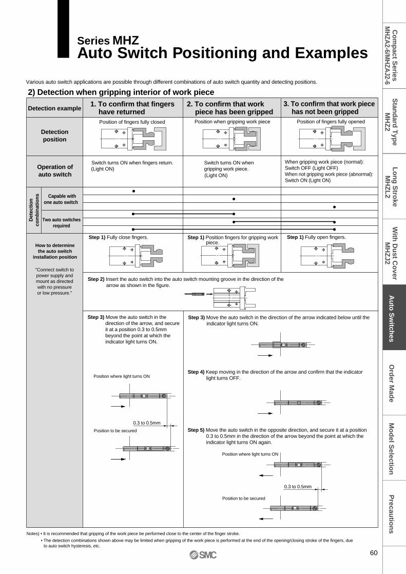
2) Detection when gripping interior of work piece
Position of fingers fully closed Position of fingers fully opened
•
•
•
•
•
•
••
Step 1) Fully close fingers. Step 1) Fully open fingers.
Position where light turns ON
Position to be secured
Position where light turns ON
Position to be secured
1. To confirm that fingershave returned
2. To confirm that workpiece has been gripped
3. To confirm that work piecehas not been gripped
Switch turns ON when fingers return.(Light ON)
Switch turns ON when gripping work piece. (Light ON)
When gripping work piece (normal):Switch OFF (Light OFF)When not gripping work piece (abnormal):Switch ON (Light ON)
Various auto switch applications are possible through different combinations of auto switch quantity and detecting positions.
Position when gripping work piece
"Connect switch to power supply and mount as directed with no pressure or low pressure."
Step 1) Position fingers for gripping work piece.
Step 2) Insert the auto switch into the auto switch mounting groove in the direction of the arrow as shown in the figure.
Step 3) Move the auto switch in the direction of the arrow, and secure it at a position 0.3 to 0.5mm beyond the point at which the indicator light turns ON.
Notes) • It is recommended that gripping of the work piece be performed close to the center of the finger stroke.
• The detection combinations shown above may be limited when gripping of the work piece is performed at the end of the opening/closing stroke of the fingers, due to auto switch hysteresis, etc.
Step 3) Move the auto switch in the direction of the arrow indicated below until the indicator light turns ON.
Step 4) Keep moving in the direction of the arrow and confirm that the indicator light turns OFF.
Step 5) Move the auto switch in the opposite direction, and secure it at a position 0.3 to 0.5mm in the direction of the arrow beyond the point at which the indicator light turns ON again.
0.3 to 0.5mm
0.3 to 0.5mm
•
60
Series MHZAuto Switch Positioning and Examples
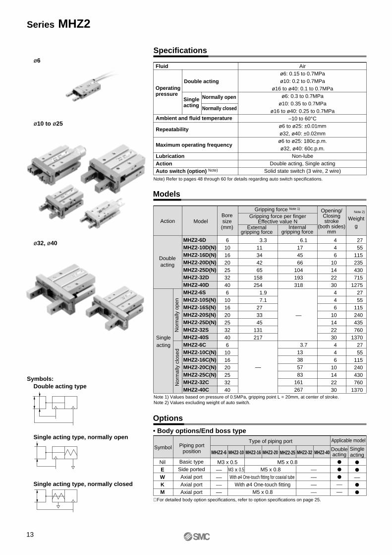
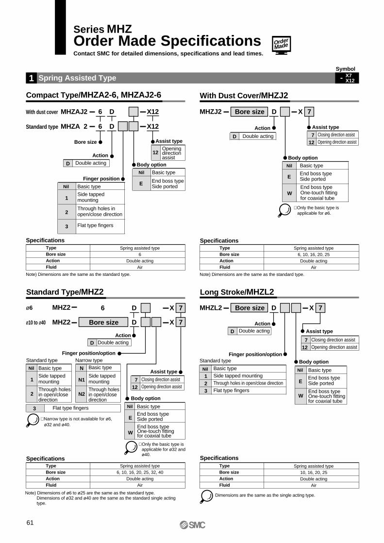
Spring Assisted Type
SpecificationsTypeBore sizeActionFluid
1
Assist type
Body option
Finger position
Action
Bore size
D Double acting
Note) Dimensions are the same as the standard type.
Spring assisted type6
Double actingAir
Basic type
Side tappedmounting
Through holes inopen/close direction
Flat type fingers
Nil
1
2
3
DMHZA 2Standard type 6 X12
DMHZAJ2With dust cover 6 X12
Openingdirectionassist
12
Basic type
End boss typeSide ported
Nil
E
Compact Type/MHZA2-6, MHZAJ2-6
SpecificationsTypeBore sizeActionFluid
Spring assisted type6, 10, 16, 20, 25, 32, 40
Double actingAir
MHZ2ø10 to ø40
MHZ2ø6
Standard Type/MHZ2
Bore size D 7X
6 D 7X
Assist type
Body option
Finger position/option
ActionD Double acting
Standard type
Basic type
Side tappedmounting
Through holesin open/closedirection
Nil
1
2
Basic type
Side tappedmounting
Through holes in open/closedirection
N
N1
N2
Narrow type
Flat type fingers3
Closing direction assistOpening direction assist
712
End boss typeSide ported
End boss typeOne-touch fitting for coaxial tube
E
W
Basic typeNil
SpecificationsTypeBore sizeActionFluid
Body option
Action
D Double acting
Note) Dimensions are the same as the standard type.
Spring assisted type6, 10, 16, 20, 25Double acting
Air
With Dust Cover/MHZJ2
Long Stroke/MHZL2
SpecificationsTypeBore sizeActionFluid
Dimensions are the same as the single acting type.
Spring assisted type10, 16, 20, 25Double acting
Air
MHZL2 Bore size D 7X
MHZJ2 Bore size 7XD
Assist type
Body optionFinger position/option
Action
D Double acting
Standard type
Basic typeSide tapped mountingThrough holes in open/close directionFlat type fingers
Nil
123
Closing direction assistOpening direction assist
712
End boss typeSide ported
End boss typeOne-touch fittingfor coaxial tube
E
W
Basic typeNil
Assist typeClosing direction assistOpening direction assist
712
End boss typeSide ported
End boss typeOne-touch fitting for coaxial tube
E
W
Basic typeNil
Symbol
- X7X12
∗ Only the basic type is applicable for ø6.
∗ Narrow type is not available for ø6, ø32 and ø40.
∗ Only the basic type is applicable for ø32 and ø40.
Note) Dimensions of ø6 to ø25 are the same as the standard type.Dimensions of ø32 and ø40 are the same as the standard single acting type.
Series MHZOrder Made SpecificationsContact SMC for detailed dimensions, specifications and lead times.
61
OrderMade
Note 1) The condition in which the needle is tightened gently until it stops.
Specifications
Dimensions
TypeBore sizeActionFluid
Installation of a variable throttle allows adjustment of the finger opening/closing speed.
With needle10, 16, 20, 25Double acting
Air
Guide for internal needle adjustmentModel
MHZ2-10D-X46MHZ2-16D-X46MHZ2-20D-X46MHZ2-25D-X46
Number of rotations from fully closed needle condition Note 1)
1/4 to 1/21/2 to 1
1 to 1 1/21 1/2 to 2
With Needle (with Variable Throttle)
Action
D Double acting
Bore sizeMHZ2
Finger position/optionStandard type
Basic type
Side tappedmounting
Through holes inopen/close direction
Nil
1
2
Basic type
Side tappedmounting
Through holes inopen/close direction
N
N1
N2
Narrow type
Flat type fingers3
D X46
A
BD
C width across flats
Model A
9
7.5
10
10.7
B
11
13
15
20
C
4.5
7
7
7
D∗
5.2
5.8
6
6.2
MHZ2-10D-X46MHZ2-16D-X46MHZ2-20D-X46MHZ2-25D-X46
Adjust so that the finger opening/closing speed will be no greater than necessary.If the finger opening/closing speed is greater than necessary, impact forces acting on the fingers and other parts will increase. This can cause a loss of repeatability when gripping work pieces and have an adverse effect on the life of the unit.
Body option
End boss typeSide ported
End boss type One-touch fitting for coaxial tube
E
W
Basic typeNil
Symbol
-X462
∗ Not available for ø6, ø32 and ø40.
Dimensions other than the above are identical to the standard type; refer to pages 18 through 21.∗ Reference values to establish criteria for needle adjustment.
62
Order Made Specifications Series MHZP
recautio
ns
Mo
del S
election
Co
mp
act Series
MH
ZA2-6/M
HZA
J2-6S
tand
ard T
ype
MH
Z2
Au
to S
witch
esL
on
g S
troke
MH
ZL
2W
ith D
ust C
over
MH
ZJ2
Ord
er Mad
e
Specifications
Dimensions
TypeBore sizeActionFluid
Bore sizeMHZ2
Finger position
Flat finger type10, 16, 20, 25
Double acting, Single acting (normally open, normally closed)Air
D X51
The flat finger type can be selected depending on the intended application.
Dimensions other than the above are identical to the standard type; refer to pages 18 through 21.
with respect to work piece weightWork piece weight: 0.1kg
Gripping point distance: L = 30mm
Operating pressure: 0.4MPa
Gripping point L mm
Grip
ping
forc
e N
Confirmation of conditions Calculation of required gripping force Selection of model from gripping force graph
Example
Gripping method: External gripping
Selection procedure
Confirmation of gripping force
Confirm gripping force Confirm external force on fingersConfirm gripping pointStep 1 Step 2 Step 3
Step 1
10 20 30 40
10
20
30
40
50 60
24
50Pressure 0.7MPa
0.2MPa0.3MPa
0.4MPa0.5MPa
0.6MPa
When gripping a work piece as in the figure to the left, and with the following definitions,F: Gripping force (N)µ: Coefficient of friction between the attachments and the work piecem: Work piece mass (kg)g: Gravitational acceleration ( = 9.8m/s²)mg: Work piece weight (N)the conditions under which the work piece will not drop are
2 x µF > mg
and therefore, mgF > ––––––– 2 x µ
With "a" representing the safety margin, F is determined by the following formula:
mgF = ––––––– x a 2 x µ
Number of fingersWhen µ = 0.2 When µ = 0.1 mgF = ––––––– x 4 2 x 0.2
= 10 x mg
mgF = ––––––– x 4 2 x 0.1
= 20 x mg
10 x work piece weight 20 x work piece weight
mg
µF
F F
µF
• Although differences will exist depending upon factors such as shape and the coefficient of friction between the attachments and the work pieces, select a model which will provide a gripping force at least 10 to 20 times Note) greater than the work piece weight.
• Furthermore, in cases with high acceleration or impact, etc., it is necessary to allow an even greater margin of safety.
Example: When it is desired to set the gripping force at 20 times or more above the work piece weight.Required gripping force = 0.1kg x 20 x 9.8m/s² (approx.) 19.6N or more
• Selecting MHZ2-16D. A gripping force of 24N is obtained from the intersection point of gripping point distance L = 30mm and pressure of 0.4MPa.
• The gripping force is 24.5 times greater than the work piece weight, and therefore satisfies a gripping force setting value of 20 times or more.
"Gripping force at least 10 to 20 times the work piece weight"The "10 to 20 times or more of the work piece weight" recommended by SMC is calculated with a safety margin of a=4, which allows for impacts that occur during normal transportation, etc.
Note) Even in cases where the coefficient of friction is greater than µ= 0.2, for reasons of safety, select a gripping force which is at least 10 to 20 times greater than the work piece weight, as recommended by SMC.It is necessary to allow a greater safety margin for high accelerations and strong impacts, etc.
Model Selection
Note) For further details, refer to the model selection illustration.
Model selection illustration
0
Series MHZ
Model Selection
65
MHZ2-32D
MHZ2-40D
Effective gripping force: Series MHZ2/Double acting/External gripping force
MHZA2, MHZ2, MHZL2
External gripping force External gripping force
F
F
L
0.6MPa
0.4MPa
0.2MPa
Step 1
MHZ2-25D/MHZL2-25D
60
80
100
40
20
0 20 40 60 80 100
Gripping point L mm
Grip
ping
forc
e N
250
200
100
150
50
0 50 100 150
Gripping point L mm
Grip
ping
forc
e N
250
300
350
400
200
100
150
50
0 50 100 150 200
Gripping point L mm
Grip
ping
forc
e N
6
4
2
0 10 20 30
Gripping point L mm
Grip
ping
forc
e N
MHZ2-6D/MHZA2-6D
External gripping
• Expressing the effective gripping force The effective gripping force shown in the graphs to the right is expressed as F, which is the impellent force of one finger, when both fingers and attachments are in full con-tact with the work piece as shown in the fig-ure below.
MHZ2-10D/MHZL2-10D
MHZ2-16D/MHZL2-16D
MHZ2-20D/MHZL2-20D
0.6MPa0.5MPa
0.4MPa0.3MPa0.2MPa
20
15
10
0
5
10 20 30 40 50
Gripping point L mm
Grip
ping
forc
e N
0.6MPa
0.5MPa
0.4MPa0.3MPa
0.2MPa
50
40
30
20
10
0 10 20 30 40 50 60
Gripping point L mm
Grip
ping
forc
e N
0.6MPa
0.5MPa
0.4MPa
0.3MPa
0.2MPa
60
50
40
30
20
10
0 20 40 60 80
Gripping point L mm
Grip
ping
forc
e N
Pressure 0.7MPa
0.5MPa0.4MPa0.3MPa0.2MPa
Pressure 0.7MPa
Pressure 0.7MPa
Pressure 0.7MPa
Pressure 0.7MPa
0.6MPa0.5MPa
0.4MPa
Pressure 0.7MPa
0.3MPa
Pressure 0.7MPa
0.6MPa
0.3MPa
0.5MPa
0.4MPa
0.3MPa
0.2MPa
0.6MPa
0.5MPa
0.2MPa
66
Model Selection Series MHZP
recautio
ns
Mo
del S
election
Co
mp
act Series
MH
ZA2-6/M
HZA
J2-6S
tand
ard T
ype
MH
Z2
Au
to S
witch
esL
on
g S
troke
MH
ZL
2W
ith D
ust C
over
MH
ZJ2
Ord
er Mad
e
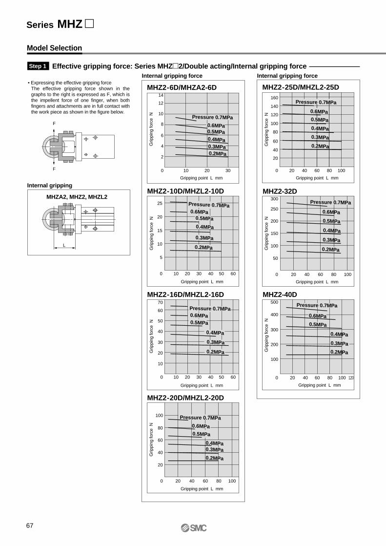
MHZ2-32D
MHZ2-40D
Effective gripping force: Series MHZ2/Double acting/Internal gripping forceInternal gripping force Internal gripping force
MHZA2, MHZ2, MHZL2
L
Step 1
MHZ2-25D/MHZL2-25D
0.6MPa
0.4MPa
0.3MPa
0.4MPa
0.2MPa
100
120
140
160
80
60
40
20
0 20 40 60 80 100
Gripping point L mm
Grip
ping
forc
e N
100
150
200
250
300
50
0 20 40 60 80 100
Gripping point L mm
Grip
ping
forc
e N
100
200
300
400
500
0 20 40 60 80 100 120
Gripping point L mm
Grip
ping
forc
e N
14
12
10
0
2
4
6
8
10 20 30
Gripping point L mm
Grip
ping
forc
e N
MHZ2-6D/MHZA2-6D
Internal gripping
Model Selection
• Expressing the effective gripping forceThe effective gripping force shown in the graphs to the right is expressed as F, which is the impellent force of one finger, when both fingers and attachments are in full contact with the work piece as shown in the figure below.
MHZ2-10D/MHZL2-10D
MHZ2-16D/MHZL2-16D
MHZ2-20D/MHZL2-20D
0.6MPa0.5MPa
0.4MPa
0.3MPa
0.2MPa
25
20
15
10
0
5
10 20 30 40 50 60
Gripping point L mm
Grip
ping
forc
e N
0.6MPa0.5MPa
0.4MPa
0.3MPa
0.2MPa
60
70
50
40
30
20
10
0 10 20 30 40 50 60
Gripping point L mm
Grip
ping
forc
e N
0.6MPa0.5MPa
0.4MPa0.3MPa
0.2MPa
100
80
60
40
20
0 20 40 60 80 100
Gripping point L mm
Grip
ping
forc
e N
Pressure 0.7MPa0.6MPa0.5MPa0.4MPa0.3MPa0.2MPa
Pressure 0.7MPa
Pressure 0.7MPa
Pressure 0.7MPa
F
F
Pressure 0.7MPa
0.6MPa
0.5MPa
0.3MPa
Pressure 0.7MPa
0.5MPa
0.2MPa
Pressure 0.7MPa
0.6MPa0.5MPa
0.4MPa
0.3MPa
0.2MPa
Series MHZ
67
MHZ2-32S
MHZ2-40S
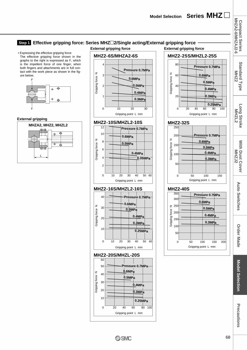
Effective gripping force: Series MHZ2/Single acting/External gripping forceExternal gripping force External gripping force
F
F
L
Step 1
MHZ2-25S/MHZL2-25S
Gripping point L mm
Grip
ping
forc
e N
MHZ2-6S/MHZA2-6S
0.25MPa
0.4MPa
0.3MPa
60
80
20
40
0 20 40 60 80 100
Gripping point L mm
Grip
ping
forc
e N
150
200
250
50
100
0 50 100 150
Gripping point L mm
Grip
ping
forc
e N 0.5MPa
0.3MPa150
200
250
300
350
50
100
0 50 100 150 200
Gripping point L mm
Grip
ping
forc
e N 3
4
1
2
0 10 20 30
MHZA2, MHZ2, MHZL2
External gripping
• Expressing the effective gripping forceThe effective gripping force shown in the graphs to the right is expressed as F, which is the impellent force of one finger, when both fingers and attachments are in full con-tact with the work piece as shown in the fig-ure below.
MHZ2-10S/MHZL2-10S
MHZ2-16S/MHZL2-16S
MHZ2-20S/MHZL-20S
Gripping point L mm
Grip
ping
forc
e N
Gripping point L mm
Grip
ping
forc
e N
Gripping point L mm
Grip
ping
forc
e N
0.6MPa
0.5MPa
0.4MPa0.35MPa
12
10
8
0
2
4
6
10 20 30 40 50 60
0.6MPa
0.5MPa
0.4MPa
0.3MPa
0.25MPa
40
10
20
30
0 10 20 30 40 50 60
40
60
50
10
20
30
0 20 40 60 80 100
0.6MPa
0.5MPa
0.4MPa
0.3MPa
0.25MPa
Pressure 0.7MPa
0.6MPa
0.5MPa
Pressure 0.7MPa
Pressure 0.7MPa
Pressure 0.7MPa
Pressure 0.7MPa
0.6MPa
0.4MPa
Pressure 0.7MPa
Pressure 0.7MPa
0.6MPa
0.5MPa
0.4MPa
0.3MPa
0.6MPa
0.5MPa0.4MPa
0.3MPa
68
Model Selection Series MHZ P
recautio
ns
Mo
del S
election
Co
mp
act Series
MH
ZA2-6/M
HZA
J2-6S
tand
ard T
ype
MH
Z2
Au
to S
witch
esL
on
g S
troke
MH
ZL
2W
ith D
ust C
over
MH
ZJ2
Ord
er Mad
e
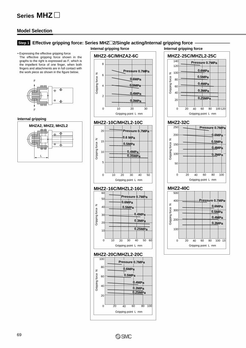
MHZ2-32C
MHZ2-40C
Effective gripping force: Series MHZ2/Single acting/Internal gripping forceInternal gripping force Internal gripping force
L
Step 1
MHZ2-25C/MHZL2-25CMHZ2-6C/MHZA2-6C
Gripping point L mm
Grip
ping
forc
e N
Gripping point L mm
Grip
ping
forc
e N
8
6
4
0
2
10 20 30
Pressure 0.7MPa
0.6MPa
0.5MPa
0.4MPa
0.3MPa
140
120
100
80
60
40
20
0 20 40 60 80 100120
Gripping point L mm
Grip
ping
forc
e N
250
200
100
150
50
0 20 40 60 80 100
Gripping point L mm
Grip
ping
forc
e N
500
400
200
100
300
0 20 40 60 80 100 120
MHZA2, MHZ2, MHZL2
Internal gripping
Model Selection
• Expressing the effective gripping forceThe effective gripping force shown in the graphs to the right is expressed as F, which is the impellent force of one finger, when both fingers and attachments are in full contact with the work piece as shown in the figure below.
F
F
MHZ2-10C/MHZL2-10C
MHZ2-16C/MHZL2-16C
MHZ2-20C/MHZL2-20C
Gripping point L mm
Grip
ping
forc
e N
Gripping point L mm
Grip
ping
forc
e N
Gripping point L mm
Grip
ping
forc
e N
0.6 MPa
0.5MPa
0.4MPa0.35MPa
20
15
10
0
5
10 20 30 40 50
0.6MPa0.5MPa
0.4MPa
0.3MPa
0.25MPa
60
50
40
30
20
10
0 10 20 30 40 50 60
0.6MPa
0.5MPa
0.4MPa
0.3MPa0.25MPa
100
80
60
40
20
0 20 40 60 80 100
Pressure 0.7MPa
Pressure 0.7MPa
Pressure 0.7MPa
Pressure 0.7MPa
0.6MPa
0.5MPa
0.4MPa
0.3MPa
Pressure 0.7MPa
0.6MPa
0.5MPa
0.4MPa
0.3MPa
Pressure 0.7MPa
0.6MPa
0.5MPa
0.4MPa
0.3MPa
0.25MPa
Series MHZ
69
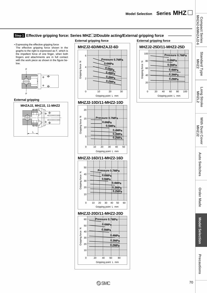
MHZJ2-16D/11-MHZ2-16D
MHZJ2-20D/11-MHZ2-20D
Effective gripping force: Series MHZ2/Double acting/External gripping force
MHZAJ2, MHZJ2, 11-MHZ2
External gripping force External gripping force
F
F
20
15
10
0
5
10 20 30 40 50
Gripping point L mm
Grip
ping
forc
e N
50
40
30
20
10
0 10 20 30 40 50 60
Gripping point L mm
Grip
ping
forc
e N
60
50
40
30
20
10
0 20 40 60 80
Gripping point L mm
Grip
ping
forc
e N
Step 1
MHZJ2-25D/11-MHZ2-25D
60
80
100
40
20
0 20 40 60 80 100
Gripping point L mm
Grip
ping
forc
e N
6
4
2
0 10 20 30
Gripping point L mm
Grip
ping
forc
e N
MHZJ2-6D/MHZAJ2-6D
External gripping
• Expressing the effective gripping force The effective gripping force shown in the graphs to the right is expressed as F, which is the impellent force of one finger, when both fingers and attachments are in full contact with the work piece as shown in the figure be-low.
MHZJ2-10D/11-MHZ2-10D
Pressure 0.7MPa
0.5MPa0.4MPa0.3MPa0.2MPa
Pressure 0.7MPa
0.6MPa
0.5MPa
0.4MPa
0.3MPa0.2MPa
0.6MPa0.5MPa
0.4MPa0.3MPa0.2MPa
Pressure 0.7MPa
0.6MPa0.5MPa
0.4MPa
0.2MPa0.3MPa
Pressure 0.7MPa
0.6MPa
0.5MPa
0.4MPa
0.3MPa
0.2MPa
L
Pressure 0.7MPa0.6MPa
70
Model Selection Series MHZ P
recautio
ns
Mo
del S
election
Co
mp
act Series
MH
ZA2-6/M
HZA
J2-6S
tand
ard T
ype
MH
Z2
Au
to S
witch
esL
on
g S
troke
MH
ZL
2W
ith D
ust C
over
MH
ZJ2
Ord
er Mad
e
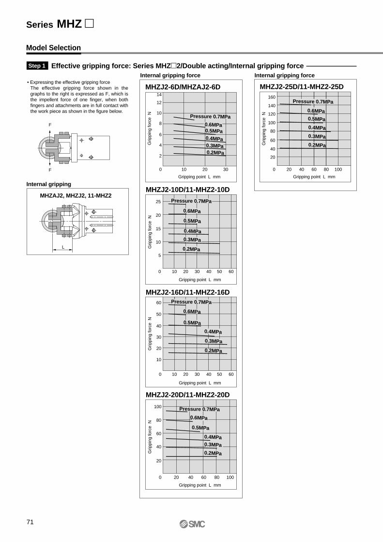
Effective gripping force: Series MHZ2/Double acting/Internal gripping forceInternal gripping force Internal gripping force
MHZAJ2, MHZJ2, 11-MHZ2
F
F
L
Step 1
MHZJ2-10D/11-MHZ2-10D
MHZJ2-16D/11-MHZ2-16D
MHZJ2-20D/11-MHZ2-20D
MHZJ2-25D/11-MHZ2-25D
25
20
15
10
0
5
10 20 30 40 50 60
Gripping point L mm
Grip
ping
forc
e N
60
50
40
30
20
10
0 10 20 30 40 50 60
Gripping point L mm
Grip
ping
forc
e N
100
80
60
40
20
0 20 40 60 80 100
Gripping point L mm
Grip
ping
forc
e N
0.5MPa0.4MPa
0.2MPa
100
120
140
160
80
60
40
20
0 20 40 60 80 100
Gripping point L mm
Grip
ping
forc
e N
14
12
10
0
2
4
6
8
10 20 30
Gripping point L mm
Grip
ping
forc
e N
MHZJ2-6D/MHZAJ2-6D
Internal gripping
Model Selection
• Expressing the effective gripping forceThe effective gripping force shown in the graphs to the right is expressed as F, which is the impellent force of one finger, when both fingers and attachments are in full contact with the work piece as shown in the figure below.
Pressure 0.7MPa0.6MPa
0.3MPa
Pressure 0.7MPa
0.6MPa
0.5MPa
0.4MPa
0.3MPa
0.2MPa
Pressure 0.7MPa
0.6MPa
0.5MPa
0.4MPa
0.3MPa
0.2MPa
Pressure 0.7MPa
0.6MPa0.5MPa
0.4MPa
0.3MPa
0.2MPa
Pressure 0.7MPa
0.6MPa
0.4MPa0.3MPa
0.2MPa
0.5MPa
Series MHZ
71
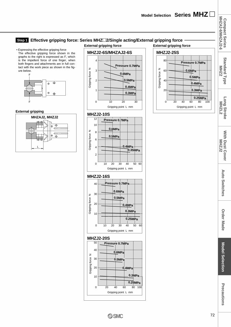
MHZJ2-10S
MHZJ2-16S
MHZJ2-20S
Effective gripping force: Series MHZ2/Single acting/External gripping forceExternal gripping force External gripping force
F
F
Gripping point L mm
Grip
ping
forc
e N
Gripping point L mm
Grip
ping
forc
e N
Gripping point L mm
Grip
ping
forc
e N
12
10
8
0
2
4
6
10 20 30 40 50 60
40
10
20
30
0 10 20 30 40 50 60
40
50
10
20
30
0 20 40 60 80 100
Step 1
MHZJ2-25S
Gripping point L mm
Grip
ping
forc
e N
MHZJ2-6S/MHZAJ2-6S
0.4MPa
0.3MPa
60
80
20
40
0 20 40 60 80 100
Gripping point L mm
Grip
ping
forc
e N 3
4
1
2
0 10 20 30
MHZAJ2, MHZJ2
External gripping
• Expressing the effective gripping forceThe effective gripping force shown in the graphs to the right is expressed as F, which is the impellent force of one finger, when both fingers and attachments are in full con-tact with the work piece as shown in the fig-ure below.
Pressure 0.7MPa
0.6MPa
0.5MPa
Pressure 0.7MPa
0.6MPa
0.5MPa
0.4MPa0.35MPa
0.6MPa
0.5MPa
0.4MPa
0.3MPa
0.25MPa
Pressure 0.7MPa
Pressure 0.7MPa
0.6MPa
0.4MPa
0.3MPa
0.25MPa
0.5MPa
L
Pressure 0.7MPa
0.6MPa
0.5MPa
0.4MPa
0.25MPa
0.3MPa
72
Model Selection Series MHZ P
recautio
ns
Mo
del S
election
Co
mp
act Series
MH
ZA2-6/M
HZA
J2-6S
tand
ard T
ype
MH
Z2
Au
to S
witch
esL
on
g S
troke
MH
ZL
2W
ith D
ust C
over
MH
ZJ2
Ord
er Mad
e
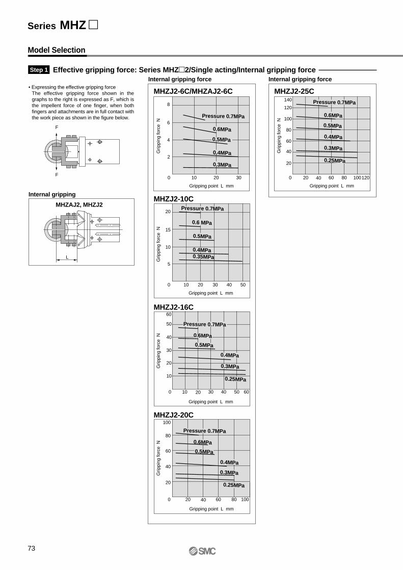
MHZJ2-6C/MHZAJ2-6C
MHZJ2-10C
MHZJ2-16C
MHZJ2-20C
Effective gripping force: Series MHZ2/Single acting/Internal gripping forceInternal gripping force Internal gripping force
L
Step 1
MHZJ2-25C
Gripping point L mm
Grip
ping
forc
e N
Gripping point L mm
Grip
ping
forc
e N
Gripping point L mm
Grip
ping
forc
e N
Gripping point L mm
Grip
ping
forc
e N
20
15
10
0
5
10 20 30 40 50
Gripping point L mm
Grip
ping
forc
e N
8
6
4
0
2
10 20 30
60
50
40
30
20
10
0 10 20 30 40 50 60
100
80
60
40
20
0 20 40 60 80 100
140
120
100
80
60
40
20
0 20 40 60 80 100120
MHZAJ2, MHZJ2
Internal gripping
Model Selection
• Expressing the effective gripping forceThe effective gripping force shown in the graphs to the right is expressed as F, which is the impellent force of one finger, when both fingers and attachments are in full contact with the work piece as shown in the figure below.
F
F
Pressure 0.7MPa
0.6MPa
0.5MPa
0.4MPa
0.3MPa
Pressure 0.7MPa
0.6 MPa
0.5MPa
0.4MPa0.35MPa
Pressure 0.7MPa
0.6MPa
0.5MPa
0.4MPa
0.3MPa
0.25MPa
Pressure 0.7MPa
0.6MPa
0.5MPa
0.4MPa
0.3MPa
0.25MPa
Pressure 0.7MPa
0.6MPa
0.5MPa
0.4MPa
0.3MPa
0.25MPa
Series MHZ
73
MHZ2-6 MHZ2-25/11-MHZ2-25
MHZ2-16/11-MHZ2-16
MHZ2-32
MHZ2-20/11-MHZ2-20
MHZ2-40
External gripping External gripping
Confirmation of gripping point: Series MHZ/External grippingStep 2
MHZ2, 11-MHZ2
MHZAJ2, MHZJ2
L
L
HH
Grippingpoint
Grippingpoint
50
40
30
20
10
0 10 20 30 40 50 60
60
Gripping point L mm
Ove
rhan
g H
mm
80
60
40
20
0 20 40 60 80 100
100
Gripping point L mm
Ove
rhan
g H
mm
0.3MPa
0.4MPa
0.5MPa
0.6MPa
0.7MPa
0.3MPa0.4MPa
0.5MPa
80
60
40
20
0 20 40 60 80 100 120
100
120
Gripping point L mm
Ove
rhan
g H
mm
50
0 50 100 150
100
150
Gripping point L mm
Ove
rhan
g H
mm
50
0 50 100 150 200
100
150
200
Gripping point L mm
Ove
rhan
g H
mm
0.7MPa
0.6MPa
0.7MPa0.6MPa
0.5MPa
External gripping
MHZ2-10/11-MHZ2-10
0.3MPa0.4MPa
50
40
30
20
10
0 10 20 30 40 50
60
Gripping point L mm
Ove
rhan
g H
mm
40
30
20
10
0 10 20 30 40
Gripping point L mm
Ove
rhan
g H
mm
• The air gripper should be operated so that the work piece gripping point "L" and the amount of overhang "H" stay within the range shown for each operating pressure given in the graphs to the right.
• If the work piece gripping point goes beyond the range limits, this will have an adverse effect on the life of the air gripper.
Pressure 0.2MPa
Pressure 0.2MPa
0.3MPa0.4MPa
0.7MPa0.6MPa0.5MPa
Pressure 0.2MPa
Pressure 0.2MPa
0.3MPa0.4MPa
0.5MPa
0.6MPa, 0.7MPa
Pressure 0.2MPa
Pressure 0.2MPa
0.3MPa0.4MPa
0.5MPa
0.6MPa, 0.7MPa
Pressure 0.2MPa
0.3MPa0.4MPa
0.5MPa0.6MPa
0.7MPa
74
Model Selection Series MHZ P
recautio
ns
Mo
del S
election
Co
mp
act Series
MH
ZA2-6/M
HZA
J2-6S
tand
ard T
ype
MH
Z2
Au
to S
witch
esL
on
g S
troke
MH
ZL
2W
ith D
ust C
over
MH
ZJ2
Ord
er Mad
e
Model Selection
MHZ2-6
MHZ2-16/11-MHZ2-16
MHZ2-20/11-MHZ2-20
Internal gripping
Confirmation of gripping point: Series MHZ/Internal grippingStep 2
50
40
30
20
10
0 10 20 30 40 50
Gripping point L mm
Ove
rhan
g H
mm
40
30
20
10
0 10 20 30 40
Gripping point L mm
Ove
rhan
g H
mm
60
50
40
30
20
10
0 10 20 30 40 50 60
Gripping point L mm
Ove
rhan
g H
mm
60
80
40
20
0 20 40 60 80
Gripping point L mm
Ove
rhan
g H
mm
MHZ2, 11-MHZ2
L
L
HH
Grippingpoint
Grippingpoint
MHZAJ2, MHZJ2
Internal gripping
MHZ2-10/11-MHZ2-10
• The air gripper should be operated so that the work piece gripping point "L" and the amount of overhang "H" stay within the range shown for each operating pressure given in the graphs to the right.
• If the work piece gripping point goes beyond the range limits, this will have an adverse effect on the life of the air gripper.
MHZ2-25/11-MHZ2-25
MHZ2-32
MHZ2-40
Internal gripping
60
80
100
40
20
0 20 40 60 80 100
Gripping point L mm
Gripping point L mm
Ove
rhan
g H
mm
60
80
100
40
20
0 20 40 60 80 100O
verh
ang
H m
m
Gripping point L mm
60
80
100
120
40
20
0 20 40 60 80 100 120
Ove
rhan
g H
mm
Pressure 0.2MPa
0.3MPa0.4MPa0.6MPa
0.5MPa
0.7MPa
Pressure 0.2MPa
0.3MPa
0.4MPa
0.5MPa0.7MPa0.6MPa
Pressure 0.2MPa
0.3MPa
0.4MPa
0.5MPa0.7MPa
0.6MPa
Pressure 0.2MPa0.3MPa0.4MPa
0.7MPa
0.5MPa
0.6MPa
Pressure 0.2MPa
0.3MPa0.4MPa
0.5MPa
0.6MPa, 0.7MPa
0.3MPa0.4MPa0.5MPa
0.6MPa, 0.7MPaPressure 0.2MPa
Pressure 0.2MPa
0.3MPa0.4MPa0.5MPa
0.7MPa0.6MPa
Series MHZ
75
Confirmation of external force on fingers: Series MHZ2Step 3
Fv
My
L
MpL
Model
MHZ2-6
MHZ2-10
MHZ2-16
MHZ2-20
MHZ2-25
MHZ2-32
MHZ2-40
10
58
98
147
255
343
490
0.04
0.26
0.68
1.32
1.94
3
4.5
0.04
0.26
0.68
1.32
1.94
3
4.5
0.08
0.53
1.36
2.65
3.88
6
9
Maximum allowable moment
L: Distance to the point at which the load is applied (mm)
Note) Values for load and moment in the table indicate static values.
Mr
L
Calculation of allowable external force(when moment load is applied)
Calculation example
M (maximum allowable moment) (N⋅m)Allowable load F (N) = –––––––––––––––––––––––––––––– L x 10-3
∗
(∗ Unit conversion constant)
When a static load of f = 10N is operating, which applies pitch moment to point L = 30mm from the MHZ2-16D guide.
Therefore, it can be used.
0.68Allowable load F = –––––––––– 30 x 10-3
= 22.7 (N)
Load f = 10 (N) < 22.7 (N)
Pitch moment:Mp (N⋅m)
Yaw moment:My (N⋅m)
Roll moment:Mr (N⋅m)
Allowable vertical loadFv (N)
76
Model Selection Series MHZ P
recautio
ns
Mo
del S
election
Co
mp
act Series
MH
ZA2-6/M
HZA
J2-6S
tand
ard T
ype
MH
Z2
Au
to S
witch
esL
on
g S
troke
MH
ZL
2W
ith D
ust C
over
MH
ZJ2
Ord
er Mad
e
Series MHZSafety Instructions
Note 1) ISO 4414: Pneumatic fluid power -- Recommendations for the application of equipment to transmission and control systems
Note 2) JIS B 8370: General Rules for Pneumatic Equipment
Warning
Caution : Operator error could result in injury or equipment damage.
Warning : Operator error could result in serious injury or loss of life.
Danger : In extreme conditions, there is a possible result of serious injury or loss of life.
These safety instructions are intended to prevent a hazardous situation and/or equipment damage. These instructions indicate the level of potential hazard by a label of "Caution", "Warning" or "Danger". To ensure safety, be sure to observe ISO 4414 Note 1), JIS B 8370 Note 2) and other safety practices.
1. The compatibility of pneumatic equipment is the responsibility of the person who designs the pneumatic system or decides its specifications.Since the products specified here are used in various operating conditions, their compatibility for the specific pneumatic system must be based on specifications or after analysis and/or tests to meet your specific requirements.
2. Only trained personnel should operate pneumatically operated machinery and equipment.Compressed air can be dangerous if handled incorrectly. Assembly, handling or repair of pneumatic systems should be performed by trained and experienced operators.
3. Do not service machinery/equipment or attempt to remove components until safety is confirmed.
1. Inspection and maintenance of machinery/equipment should only be performed after confirmation of safe locked-out control positions.
2. When equipment is to be removed, confirm the safety process as mentioned above. Cut the supply pressure for this equipment and exhaust all residual compressed air in the system.
3. Before machinery/equipment is restarted, take measures to prevent shooting-out of cylinder piston rod, etc. (Bleed air into the system gradually to create back pressure.)
4. Contact SMC if the product is to be used in any of the following conditions:1. Conditions and environments beyond the given specifications, or if product is used outdoors.2. Installation on equipment in conjunction with atomic energy, railway, air navigation, vehicles, medical
equipment, food and beverages, recreation equipment, emergency stop circuits, press applications, or safety equipment.
3. An application which has the possibility of having negative effects on people, property, or animals, requiring special safety analysis.
77
Precau
tion
sM
od
el Selectio
nC
om
pact S
eriesM
HZA
2-6/MH
ZAJ2-6
Stan
dard
Typ
eM
HZ
2A
uto
Sw
itches
Lo
ng
Stro
keM
HZ
L2
With
Du
st Co
verM
HZ
J2O
rder M
ade
2. Even with the gripping point within thelimits of the range, make the attach-ment as light and short as possible.
3. Select a larger size gripper or use mul-tiple grippers for handling long andlarge work pieces.
Series MHZAir Gripper Precautions 1Be sure to read before handling.
3. Provide run off space in theattachments when usingfor very small or thin workpieces.If run off space is not provided, grippingbecomes unstable, and it may fail to gripproperly or the position may slip, etc.
4. Select a model which hassufficient gripping forcefor the work piece weight.Incorrect selection may lead to droppingof work pieces, etc. Refer to the modelselection criteria for each series pertain-ing to effective gripping force and workpiece weight.
5. Do not use in applicationswhere excessive externalforce or impact force willbe applied to the gripper.This may cause malfunction. ContactSMC for further information.
6. Select a model having asufficient finger openingwidth for the work piece.< In case of insufficient width >
1. Gripping becomes unstable due to vari-ations in opening width or work piece di-ameter.
1. When moving work piecespose a danger to person-nel, or there is a danger offingers being caught in agripper, etc., implementsafety measures such asmounting of protective cov-ers.
2. If circuit pressure dropsdue to a power failure ortrouble with the air supply,etc., there is a danger ofwork pieces droppingbecause of reduced grip-ping force. Implement dropprevention measures toavoid human injury anddamage to machinery.
Design Selection
1. Keep the gripping pointwithin the limits of thespecified range.When the limiting range is exceeded, anexcessively large load is applied to thefinger slide section, possibly causingpremature failure. Refer to the graph ofthe specified gripping distance range foreach series.
2. Design attachments to beas light and short as possi-ble.
1. Long and heavy attachments increasethe inertial force when opening and clos-ing the fingers. This may causeunsteady movement of the fingers andhave an adverse effect on product life.
Mounting
1. Do not scratch or gouge thegripper by dropping orbumping it when mounting .Even a slight deformation can cause in-accuracy or malfunction.
2. Tighten screws within thespecified torque rangewhen mounting the attach-ments.Tightening with a higher torque thanspecified may cause malfunction, whiletightening with a lower torque may allowslipping of the gripping position or drop-ping of work pieces.
Mounting attachments to the fingersMount attachments by inserting bolts,etc., into the female mounting threadson the fingers and tightening with thetorque shown in the table below.
LL is too long
Gripping point
LL and H areappropriateGripping point
H
H is too long
Gripping point
H
Attachment
Selection
LGripping point
Needle shapedwork piece
Thin platework piece
Run off space
Run off space
Warning
Warning
78
Selection
Warning2. Causes detection failure when using an
auto switch. Ensure a stroke sufficientto allow for hysteresis, after referring tothe information on auto switch hystere-sis for each series.Refer to auto switch hysteresis espe-cially when using a 2 color indicationauto switch, because the stroke may belimited by the light color setting at thetime of detection.
7. Consult with SMC in case ofa single acting type, grip-ping with spring force only.This can cause unstable gripping insome cases or return malfunction, dueto faulty operation, etc.
Note) Series MHZ2-6 and MHZJ2-6 are not available in axial mount type.
Note)
Note)
l
Mounting
Use the hole at the end of the body for positioning, etc.
l
l
Cle
aran
ceC
lear
ance
With clearance
Without clearance
Impact load
Cle
aran
ceC
lear
ance
With clearance
Without clearance
Impact load
Cle
aran
ce Impact load
Turningover
Warning3. When mounting the air gripper, tighten screws properly at a
torque value within the limits of the specified range.Tightening at a torque above the limits of the range can cause mal-function, while tightening at a lower torque can cause slipping or dropping of work pieces, etc.
1. Avoid twisting the fingers when mounting the attach-ments.This may cause losseness and loss of accuracy.
2. Adjust and confirm that ex-ternal forces are not applied to the fingers.Fingers may become loose or be dam-aged by continual lateral or impact load. Provide clearance to prevent the work piece or attachments from striking against any objects at the stroke end.
Caution
1) Stroke end with fingers open
2) Stroke end with air gripper moving
3) When turning over
Mounting of air gripperAxial mount type (tapped holes)
Mounting of air gripperSide mount type(tapped holes, through holes)• Using tapped holes
Note) When mounting D-Y59, D-Y69 and D-Y7P type auto switches, only the tapped hole type is appli-cable.The screw-in depth should follow the table below so that the end of the bolt does not press the body of the auto switch.
Vertical mount type (tapped holes)
• Using through holes
79
Series MHZAir Gripper Precautions 2Be sure to read before handling.
Series MHZAir Gripper Precautions 3Be sure to read before handling.
Maintenance
3. Perform thorough align-ment so that excessiveforce is not applied to thefingers during the workpiece gripping operation.Particularly when performing a trial run,operation should be done manually orwith low cylinder pressure and speed,while confirming that there is no impactor other unsafe conditions.
4. If the closing speed of thefingers is greater than nec-essary, backlash and dam-age can occur due to theinertia of the fingers andattachments. Therefore, aspeed controller should beinstalled and adjusted sothat there is no impact.
Applicable speed controllers
Air gripper directcoupling type: AS1200-M5
AS2200-01, etc.
In-line type: Series AS1000AS1001F, AS2051F, etc.
1. Preparation before pipingBefore piping is connected, it should bethoroughly blown out with air (flushing)or washed to remove chips, cutting oiland other debris from inside the pipe.
2. Wrapping of pipe tapeWhen screwing together pipes and fit-tings, etc., be certain that chips from thepipe threads and sealing material do notget inside the product.
Also, when pipe tape is used, leave 1.5to 2 thread ridges exposed at the end ofthe threads.
Operating Environment
1. In an environment whereadverse effects appear tobe especially likely, contactSMC before operating in alocation having an atmos-phere of corrosive gases,chemicals, sea water, wateror water vapor, or wherecontact with any of thesemay occur. There can be adverseeffects on dust covers andseals, etc., causing mal-function or reducing theproduct's life. After con-firming the nature of theenvironment, contact SMCregarding any questionswhich you may have.
2. Provide shading in loca-tions which receive directsunlight.
3. Do not use in locationswhere vibration or impactoccurs.
4. Do not use in locationsnear heat sources whereradiated heat will bereceived.
5. Attach a cover or other pro-tection in locations wherethere will be exposure toexcessive amounts of dustor cutting oil.
1. The non-lube type air grip-per is lubricated at the fac-tory, and can be used with-out any further lubrication.In the event that lubrication will beapplied, use Class 1 turbine oil (withoutadditives) ISO VG32. Moreover, oncelubrication is applied, it must be contin-ued.
If lubrication is later stopped, malfunc-tion can occur due to loss of the originallubricant.
1. Do not allow personnel toenter or place objects intothe carrying path of the airgripper.This can cause injury or accidents, etc.
2. Do not put hands, etc., inbetween the air gripper fin-gers or attachments.This can cause injury or accidents, etc.
3. When removing the airgripper, first confirm thatno work pieces are beingheld and then release thecompressed air beforeremoving the air gripper.If a work piece is still being held, there isa danger of it being dropped.
Aligned
Not aligned
Impact load
Lubrication
PipingMounting
6. Contact SMC before usingin an environment whereadverse effects appearparticularly likely.
Operating Environment
Caution Caution Warning
Warning
Warning
Caution
80
Precau
tion
sM
od
el Selectio
nC
om
pact S
eriesM
HZA
2-6/MH
ZAJ2-6
Stan
dard
Typ
eM
HZ
2A
uto
Sw
itches
Lo
ng
Stro
keM
HZ
L2
With
Du
st Co
verM
HZ
J2O
rder M
ade
81
Series MHZAuto Switch Precautions 1Be sure to read before handling.
1. Confirm the specifications.Read the specifications carefully anduse this product appropriately. Theproduct may be damaged or malfunctionif it is used outside the range of specifi-cations for load current, voltage, tem-perature or impact.
2. Take precautions whenmultiple air grippers areused close together.When multiple auto switch air grippersare used in close proximity, magneticfield interference may cause the switch-es to malfunction. Maintain a minimumair gripper separation of 40mm. (Whenthe allowable separation is indicated foreach air gripper series, use the specifiedvalue.)
3. Pay attention to the lengthof time that a switch is ONat an intermediate strokeposition.When an auto switch is placed at anintermediate position of the stroke and aload is driven at the time the pistonpasses, the auto switch will operate, butif the speed is too great the operatingtime will be shortened and the load maynot operate properly. The maximumdetectable piston speed is:
4. Keep wiring as short aspossible.<Solid state switch>Although wire length should not affectswitch function, use a wire 100m orshorter.
5. Take precautions for the in-ternal voltage drop of theswitch.<Solid state switch>Generally, the internal voltage drop willbe greater with a 2 wire solid state autoswitch than with a reed switch.
• Take note that there will be a large volt-age drop if auto switches are connectedin series as shown below. (Refer to inter-nal voltage drop in the auto switch spec-ifications.)
[The voltage drop will be "n" times larg-er when "n" auto switches are connect-ed.]
Even though auto switches operate nor-mally, the load may not operate.
Design and Selection Mounting and Adjustment
• In the same way, when operatingbelow a specified voltage, although anauto switch may operate normally, theload may not operate. Therefore, theformula below should be satisfied afterconfirming the minimum operatingvoltage of the load.
Also, note that a 12VDC relay is not ap-plicable.
6. Pay attention to leakagecurrent.<Solid state switch>With a 2 wire solid state auto switch,current (leakage current) flows to theload to operate the internal circuit evenwhen in the OFF state.
If the criteria given in the above formulaare not met, it will not reset correctly(stays ON). Use a 3 wire switch if thisspecification will not be satisfied.
Moreover, leakage current flow to theload will be "n" times larger when "n"auto switches are connected in parallel.
7. Do not use a load that gen-erates surge voltage.<Solid state switch>Although a zener diode for surge protec-tion is connected at the output side of asolid state auto switch, damage may stilloccur if the surge is applied repeatedly.When a load, such as a relay or sole-noid, which generates surge is directlydriven, use a type of switch having abuilt-in surge absorbing element.
8. Cautions for use in aninterlock circuit.When an auto switch is used for an inter-lock signal requiring high reliability,devise a double interlock system toavoid trouble by providing a mechanicalprotection function, or by also usinganother switch (sensor) together withthe auto switch. Also perform periodicmaintenance and confirm proper opera-tion.
9. Ensure sufficient clearancefor maintenance activities.When designing an application, be sureto allow sufficient clearance for mainte-nance and inspections.
1. Do not drop or bump.Do not drop, bump or apply excessiveimpacts (1000m/s² or more for solidstate switches) while handling.
Although the body of the switch may notbe damaged, the inside of the switchcould be damaged and cause a mal-function.
2. Do not carry a cylinder bythe auto switch lead wires.Never carry a cylinder by its lead wires.This may not only cause broken leadwires, but it may cause internal ele-ments of the switch to be damaged bythe stress.
3. Mount switches using theproper fastening torque.When a switch is tightened beyond therange of fastening torque, the mountingscrews, mounting bracket or switch maybe damaged. On the other hand, tight-ening below the range of fasteningtorque may allow the switch to slip out ofposition. (Refer to page 56 regardingswitch mounting, movement and fasten-ing torque, etc.)
1. Avoid repeatedly bendingor stretching lead wires.Broken wires will result from applyingrepeated bending stress or stretchingforce to the lead wires.
2. Be sure to connect the loadbefore power is applied.<2 wire type>If the power is turned ON when an autoswitch is not connected to a load, theswitch will be instantly damagedbecause of excess current.
3. Confirm proper insulationof wiring.Be certain that there is no faulty wiringinsulation (contact with other circuits,ground fault, improper insulationbetween terminals, etc.). Damage mayoccur due to excess current flow into aswitch.
4. Do not run wiring nearpower lines or high voltagelines.Wire separately from power lines or highvoltage lines, avoiding parallel wiring orwiring in the same conduit with theselines. Control circuits containing autoswitches may malfunction due to noisefrom these other lines.
Wiring
Auto switch operating range (mm)
Load operating time (ms)x 1000
Internal voltagedrop of switch
Minimum operatingvoltage of load
Supply voltage – >
Operating current of load(OFF condition)
> Leakage current
Warning Warning
Warning
Load
V(mm/s) =
5. Do not allow short circuit ofloads.<Solid state switch>
Models D-F9(V), F9W(V) and allmodels of PNP output type switches donot have built-in short circuit protectioncircuits. If loads are short circuited, theswitches will be instantly damaged.Take special care to avoid reverse wiringwith the power supply line (brown) andthe output line (black) on 3 wire typeswitches.
6. Avoid incorrect wiring.<Solid state switch>
1) If connections are reversed on a 2 wiretype switch, the switch will not be dam-aged if protected by a protection circuit,but the switch will always stay in an ONstate. However, it is still necessary toavoid reversed connections, since theswitch could be damaged by a loadshort circuit in this condition.
2) If connections are reversed (power sup-ply line + and power supply line –) on a3 wire type switch, the switch will be pro-tected by a protection circuit. However, ifthe power supply line (+) is connected tothe blue wire and the power supply line(–) is connected to the black wire, theswitch will be damaged.
Series MHZAuto Switch Precautions 2Be sure to read before handling.
Old New
Old New
Old New
Old New
Other
1. Consult SMC concerningwater resistance, elasticityof lead wires, and usage atwelding sites, etc.
Warning
∗ Lead wire color changesLead wire colors of SMC switches havebeen changed in order to meet NECAStandard 0402 for production beginningSeptember, 1996 and thereafter. Pleaserefer to the tables provided.
Special care should be taken regardingwire polarity during the time that the oldcolors still coexist with the new colors.
Operating EnvironmentWiring
1. Never use in an atmos-phere of explosive gases.The construction of auto switches is notintended to prevent explosion. Neveruse in an atmosphere with an explosivegas since this may cause a seriousexplosion.
2. Do not use in an area wherea magnetic field is generat-ed.Auto switches will malfunction or mag-nets inside air grippers will become de-magnetized.
3. Do not use in an environ-ment where the autoswitch will be continuallyexposed to water.Although switches, except for a fewmodels, conform to IEC standard IP67construction (JIS C 0920: watertightconstruction), do not use switches inapplications where continually exposedto water splash or spray. Poor insulationor swelling of the potting resin insideswitches may cause malfunction.
4. Do not use in an environ-ment with oil or chemicals.Consult SMC if auto switches will beused in an environment with coolant,cleaning solvent, various oils or chemi-cals. If auto switches are used underthese conditions for even a short time,they may be adversely affected byimproper insulation, malfunction due toswelling of the potting resin, or harden-ing of the lead wires.
5. Do not use in an environ-ment with temperaturecycles.Consult SMC if switches are used wherethere are temperature cycles other thannormal air temperature changes, as theymay be adversely affected internally.
6. Do not use in locationswhere surge is generated.<Solid state switch>
When there are units (solenoid type lifter,high frequency induction furnace, motor,etc.) which generate a large amount ofsurge in the area around air grippers withsolid state auto switches, this may causedeterioration or damage to the switches.Avoid sources of surge generation andcrossed lines.
7. Avoid accumulation of ironwaste or close contact withmagnetic substances.When a large amount of ferrous wastesuch as machining chips or spatter isaccumulated, or a magnetic substance(something attracted by a magnet) isbrought into close proximity with an autoswitch air gripper, it may cause the autoswitch to malfunction due to a loss ofthe magnetic force inside the air gripper.
Maintenance
1. Perform the followingmaintenance periodicallyin order to prevent possi-ble danger due to unex-pected auto switch mal-function.
1) Securely tighten switch mountingscrews.
If screws become loose or the mount-ing position is dislocated, retightenthem after readjusting the mountingposition.
2) Confirm that there is no damage tolead wires.
To prevent faulty insulation, replaceswitches or repair lead wires, etc., ifdamage is discovered.
3) Confirm the lighting of the green lighton 2 color indication switches.
Confirm that the green LED is onwhen stopped at the established po-sition. If the red LED is on, the mount-ing position is not appropriate.Readjust the mounting position until
2 wire
Output (+)Output (–)
RedBlack
BrownBlue
Solid state with diagnostic output
Power supply (+)Power supply GNDOutputDiagnostic output
RedBlackWhiteYellow
BrownBlueBlack
Orange
3 wire
Power supply (+)Power supply GND Output
RedBlackWhite
BrownBlueBlack
Solid state with latch type diagnostic output
Power supply (+)
Power supply GND
Output
Latch type diagnosticoutput
Red
Black
White
Brown
Blue
Black
Warning Warning
Warning
Operating Environment
Warning
Yellow Orange
82
Precau
tion
sM
od
el Selectio
nC
om
pact S
eriesM
HZA
2-6/MH
ZAJ2-6
Stan
dard
Typ
eM
HZ
2A
uto
Sw
itches
Lo
ng
Stro
keM
HZ
L2
With
Du
st Co
verM
HZ
J2O
rder M
ade
83
EUROPESPAIN/PORTUGALSMC España, S.A.
SWEDENSMC Pneumatics Sweden AB
SWITZERLANDSMC Pneumatik AG.
UKSMC Pneumatics (U.K.) Ltd.
ASIACHINASMC (China) Co., Ltd.
HONG KONGSMC Pneumatics (Hong Kong) Ltd.
INDIASMC Pneumatics (India) Pvt. Ltd.
MALAYSIASMC Pneumatics (S.E.A.) Sdn. Bhd.
PHILIPPINESSMC Pneumatics (Philippines), Inc.
SINGAPORESMC Pneumatics (S.E.A.) Pte. Ltd.SOUTH KOREASMC Pneumatics Korea Co., Ltd.
TAIWANSMC Pneumatics (Taiwan) Co., Ltd.
THAILANDSMC Thailand Ltd.
NORTH AMERICACANADASMC Pneumatics (Canada) Ltd.
MEXICOSMC Corporation (Mexico) S.A. de C.V.USASMC Pneumatics, Inc.