“Phase-2” Scenarios Frank Zimmermann LHCC Upgrade Review February 2010 input from 2001 LHC Upgrade Feasibility Study and from numerous CARE-HHH and EuCARD-AccNet workshops special thanks to R. Assmann, R. Bailey, C. Bhat, O. Brüning, R. Calaga, H. Damerau, D. Denegri, O. Dominguez, U. Dorda, L. Evans, S. Fartoukh, R. Garoby, M. Giovannozzi, B. Goddard, N. Hessey, B. Jeanneret, E. Jensen, J.-P. Koutchouk, H. Maury Cuna, S. Myers, M. Nessi, K. Ohmi, R. Ostojic, Y. Papaphilippou, L. Rossi, F. Ruggiero, G. Rumolo, W. Scandale, D. Schulte, E. Shaposhnikova, G. Sterbini, K. Takayama, L. Tavian, T. Taylor, E. Todesco, R. Tomas and E. Tsesmelis
Transcript
“Phase-2” Scenarios
Frank ZimmermannLHCC Upgrade Review
February 2010
input from 2001 LHC Upgrade Feasibility Study and from numerous CARE-HHH and EuCARD-AccNet workshopsspecial thanks to R. Assmann, R. Bailey, C. Bhat, O. Brüning, R. Calaga, H. Damerau, D. Denegri, O. Dominguez, U. Dorda, L. Evans, S. Fartoukh, R. Garoby, M. Giovannozzi, B. Goddard, N. Hessey, B. Jeanneret, E. Jensen, J.-P. Koutchouk, H. Maury Cuna, S. Myers, M. Nessi, K. Ohmi, R. Ostojic, Y. Papaphilippou, L. Rossi, F. Ruggiero, G. Rumolo, W. Scandale, D. Schulte, E. Shaposhnikova, G. Sterbini, K. Takayama, L. Tavian, T. Taylor, E. Todesco, R. Tomas and E. Tsesmelis
Courtesy W. Fischer
SLHC
CERN ISR held luminosity world record for >2 decades
Tevatron is presentfrontier machine
factor 30
factor 10?
disclaimerLHC upgrade plans & schedule under review at:• LHC Machine Committee (weekly)• special “brainstorming” meetings• directorate retreat mid-November• Chamonix 2010 workshop (Jan. ‘10)• CERN MAC (1st mtg. 26 October)• LHC “lumi up” task force (next week)
previous assumptions & schedules are likely to change significantlyplans, scenarios & time scales being revised…
contents of this presentation1) parameters
2) the original plan; LHCb & ALICE?
3) few words about phase-I
4) constraints & collision schemes
5) recent progress (CC, LPA, e-cloud)
6) example scenarios
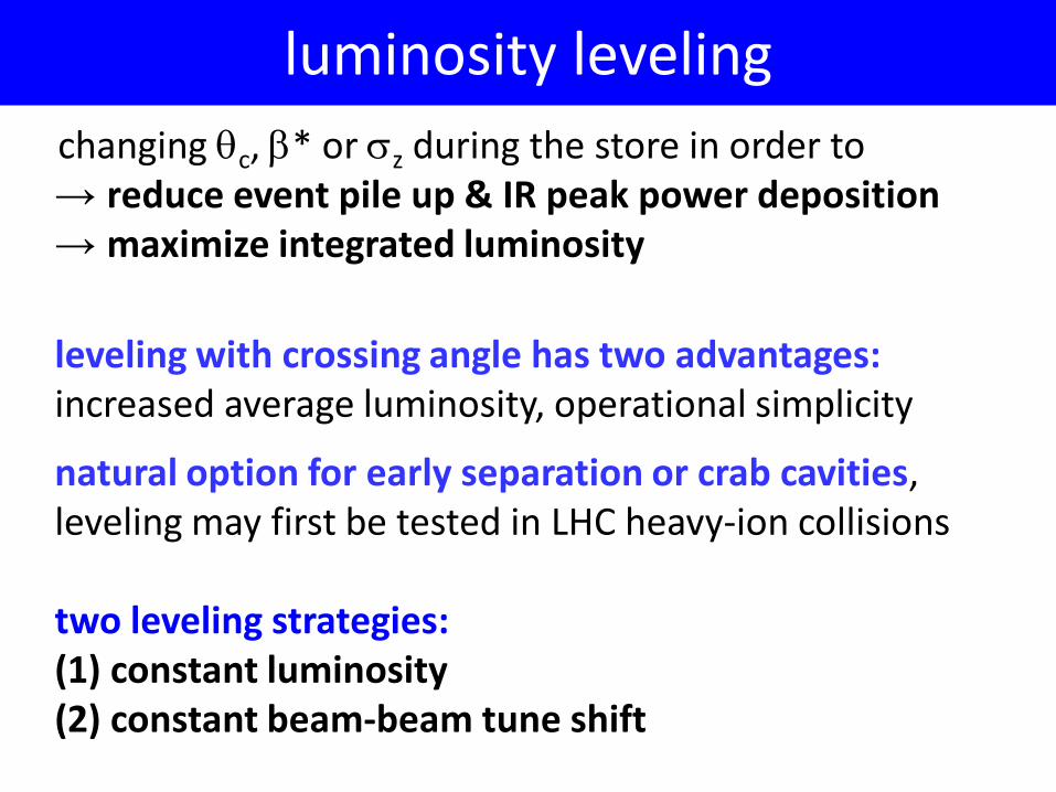
7) luminosity leveling
8) turnaround time, β*, intensity 9) conclusions & questions
• β* - IP beta function
• βx*/βy* - ratio of IP beta functions
• θc – (full) crossing angle
• εN – normalized transverse emittance
• Nb – bunch intensity
• nb – number of bunches (→sb - bunch spacing)
• longitudinal bunch profile (“flat” vs “Gaussian”)
• number of collision points (IP’s)
• Tta – turn-around time
parameters
#IP’s : the original plan – “phase 0”J.Gareyte, F. Ruggiero et al, e.g. LHC’99 workshop, LHC Project Report 626
nominal tune footprintup to 6σ with 4 IPs & nom. intensity Nb=1.15x10¹¹
tune footprint up to 6σwith nominal intensityand 2 IPs
tune footprint up to 6σwith 2 IPs at ultimateintensity Nb=1.7x10¹¹
L=1034 cm-2s-1 L=2.3x1034 cm-2s-1
“going from 4 to 2 IPs ATLAS & CMS luminosity can be increased by factor 2.3 - further, increasing crossing angle to 340 µrad, bunch length (x2), & bunch charge to Nb=2.6x10¹¹ would yield L=3.6x1034 cm-2s-1 [β*=0.5 m]”
~0.01
~0.01
~0.01
~0.01
β*~0.55 m β*~0.5 mnominal ultimate
50-ns upgradewith 25-ns collisionsin LHCb at 1-2%the luminosity
25 ns
50 ns
nominal
25 ns
ultimate & 25-ns upgrades: LHCb“late collisions” with β*~3 m?
50-ns upgrade (LPA),no collisions in LHCb
50 ns 25 ns
what about LHCb? – bunch patterns
50 ns: much reduced e- cloud! LHCb transparent
+ β∗ reduction by up to a factor of 2
+ larger aperture in triplet
- potential loss in optics flexibility
- higher chromaticity & chromatic aberrations
- more parasitic long-range beam-beam collisions
- about 1 year downtime
LHC-IR “phase-I”: merits & concerns
• total beam-beam tune shift ≤0.01 – SPS p-pbar experience
at the b-b limit, larger Piwinski angle &/or larger emittance increase luminosity!
total b-b tune shiftfor two IP’s withalternating crossing
optimization strategies:1) increase Nb with ε (e.g. controlled ε blow up at top energy)2) increase Nb with 1/Rφ & “flat” bunch Fprofile~1.4 (“LPA”) 3) vary ε as 1/Rφ (“small emittance”)4) set 1/Rφ =1 at IP and minimize β* (e.g. crab crossing)
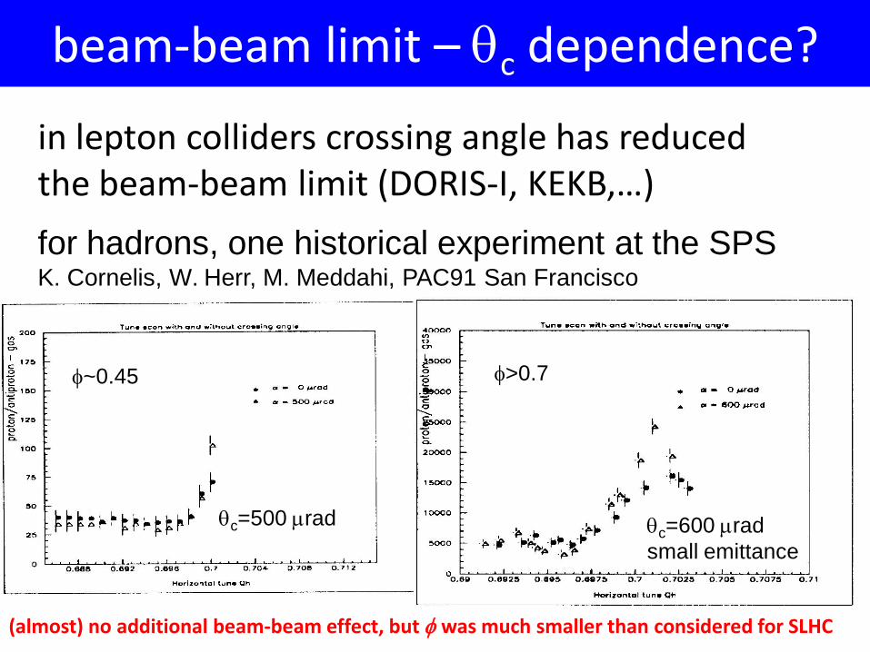
beam-beam limit – θc dependence?
for hadrons, one historical experiment at the SPSK. Cornelis, W. Herr, M. Meddahi, PAC91 San Francisco
φ~0.45 φ>0.7
θc=500 µrad θc=600 µradsmall emittance
in lepton colliders crossing angle has reduced the beam-beam limit (DORIS-I, KEKB,…)
(almost) no additional beam-beam effect, but φ was much smaller than considered for SLHC
θc
• RF crab cavity deflects head and tail in opposite direction so that collision is effectively “head on” for luminosity and tune shift
• bunch centroids still cross at an angle (easy separation)• 1st proposed in 1988, in operation at KEKB since 2007 advantages: higher geometric luminosity, easy leveling, potentially higher beam-beam tune shift
LHC-CC09 workshopLHC Crab Cavity Workshop, jointly organized by CERN, EuCARD-ACCNET, US-LARP, KEK, & DaresburyLab/Cockcroft InstituteCERN, 16-18 September 2009
~50 participants, LHC Crab Cavity Advisory Board established
CERNstatement
(Steve Myers) on LHC crab
cavitiesissued after
AccNetLHC-CC09 workshop
CERN statements (excerpts)1. KEKB success … CERN must pursue crab cavities for LHC2. … Future R&D should focus on compact cavities … suitable for
both [local and global] schemes7. Demonstration experiments should focus on differences between
electrons and protons (e.g. effect of crab-cavity noise with beam-beam, impedance, beam loading) and on reliability & machine protection which are critical for LHC
8. A beam test with KEKB crab cavity in another proton machine … useful, meaningful and sufficient …
9. Possible modifications of Interaction Region 4 during the 2013/14 shutdown
11. Crab cavity infrastructure … be included in all … LHC upgrades12. Crab cavities can increase luminosity w/o accompanying increase
in beam intensity, thereby avoiding negative side effects
CC designs presented at LHC-CC09
further crab cavity progress30 October 2009: launch of CERN working group on feasibility of KEKB crab cavity test in SPS
WG conclusions on 18 December 2009: no real showstoppers; KEKB crab cavity could be used/tested at SPS in 2012; best location found (space & available cryogenics);SPS beam test including LHC collimators; effect of RF noise; trip rates; proposal of bypass (i.e. 2 movable beam pipes w Y)
LPA progress
Example: Bunch Flattening of the LHC Beam at 7 TeVwith 400MHz and 200MHz RF systems
Mountain Range
Normal Bunch Flattened Bunch
simulation studies and experiments on LPA beam generation & stability by Chandra Bhat (US-LARP/FNAL)
flatness along the PS batch
Chandra Bhat,Heiko Damerau,et al.
transient beam loading compensation may be required
– CFC: 5 MJ/mm2 (collimators – 2 MJ/mm2 tested in TT40)• typical location: σr = 0.2 mm Ab = 0.13 mm2 (nominal
emittance, without dilution from showers).• stored energy & transverse energy density:
– nominal bunch: 130 kJ 1.0 MJ/mm2
– ultimate bunch: 190 kJ 1.5 MJ/mm2
– 2 x ultimate bunch: 380 kJ 3.0 MJ/mm2
• single bunch > 5.1e11 p exceeds damage limit of primary & secondary collimators; damage limit depends only on total beam intensity Ralph Assmann, LMC 03.02.2010
• transverse energy density rises strongly with beam energy (γ); it also scales with number of protons (Np
tot) over normalized emittance (εn):
• higher intensity or smaller emittance put similar strain on material survival!
• → “low emittance” upgrade options are no magic bullet; they solve some issues (RF, radiation, …), but do not address damage limit
• constraint from machine robustness:
ρE = γ 2 ⋅N p
tot
ε n
⋅ C
C =mpc
2
π βxβy
N ptot
εn
≤1.3 ×10²⁰ protonsm rad
Ralph Assmann, LMC 03.02.2010
constraint - beam brightness
constraint − β* range
0.55 m nominal0.50 m ultimate
0.40 m0.30 m0.25 m
0.22 m…0.14 m
IR “phase I” , larger aperture NbTi quad’s +…
IR “phase II”Nb3Sn quad’s + …
hard limit from linear chromatic correction
bunch collision rate = #bunches/beam x revolution frequency
#events per bunch crossing = cross section x luminosity / bunch collision rate
nominal #events/crossing in the detector = 6x10-26 cm2 1034 cm-2s-1 / (32 x106 s-1) = 19
e.g. 10 times higher luminosity at same #bunches→ ~200 events per crossing (detector upgrade!)
inelastic cross section
constraint – pile up
for a given luminosity value, the luminosity lifetime depends only on total beam current [w/o leveling]
luminosityintensity beam total
∝lumiτ
totIP
bbeff Ln
nNσ
τ ˆ=( ) ( )2/1
ˆ
efftLtLτ+
=
fast decay of beam intensity and luminosity (few hours) dominated by proton burn off
accompanied by crab cavities or smaller ε• Nb: factor 2 increase → 3 times higher <L>!• crab crossing: 10-100% higher <L> ; crab cavities
also provide easy leveling & increase flexibility
conclusions
• leveling with (effective) crossing angle:→1.5-3 x higher Trun , →40% lower peak pile up→(or) increase <L> by ~15%
• present luminosity optimization assumes collisionsin two IPs, LHCb collisions compatible with 50-nsspacing by adding less-intense satellite bunches
• recommended R&D focus:- understanding and mitigating intensity limits- minimization of turnaround time (3 h → ~1 h?)- new interaction-region design with (much) smaller
β* together with crab cavities and/or smaller-emittance beams
more conclusions
questions
• how much event pile up is acceptable?- is there a clear upper limit and which?
• is #events per crossing the relevant number, or e.g. #events per 50 ns?
- or in other words, is pile up limit / crossing the same for 25-ns and 50-ns spacing?
• is there an official policy or guideline for LHCb and ALICE running at the time of SLHC?; will the 4 experiments always run together? present upgrade scenarios are optimized for high luminosity in two IPs; additional collisions will contribute to ∆Qbb