+ All Categories
Home > Documents > Parametric Bay Studies V4_0 (AISC)

Parametric Bay Studies V4_0 (AISC)

Date post: 27-Nov-2015
Category:
Upload: vinceq1
View: 33 times
Download: 3 times
Share this document with a friend
Description:
Minimize the cost of the steel floor framing based on fabrication cost data. AISC Excel Spreadsheet
20
The AISC and the Steel Solutions Center logos are registered trademarks of AISC and are used under li Minimize the cost of the steel floor framing based on fabrication cost data. recognized engineering principles and information made available to AISC at the time of its preparation. While it is believed to be accurate, it has not been prepared for conventional use as an engineering or construction document and should not be used or relied upon for any specific application without competent professional examination and verification of its accuracy, suitability and applicability by a licensed engineer, architect or other professional. AISC disclaims any liability arising from the unauthorized use of the information Enter Design and Cost Parameters Run Analysis! View Input Summary Enter Project Data
Transcript

The AISC and the Steel Solutions Center logos are registered trademarks of AISC and are used under license.

Minimize the cost of the steel floor framing based on fabrication cost data.

This spreadsheet has been prepared by AISC Marketing in accordance with recognized engineering principles and information made available to AISC at the time of its preparation. While it is believed to be accurate, it has not been prepared for conventional use as an engineering or construction document and should not be used or relied upon for any specific application without competent professional examination

and verification of its accuracy, suitability and applicability by a licensed engineer, architect or other professional. AISC disclaims any liability arising from the unauthorized use of the information contained in

this spreadsheet.

Enter Design and Cost Parameters

Run Analysis!

View Input Summary

Enter Project Data

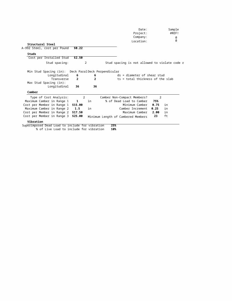
Date: SampleProject: #REF!

Company: 0 Location: 0

Structural SteelA-992 Steel, cost per Pound $0.22

StudsCost per Installed Stud $2.50

Stud spacing: 2 Stud spacing is not allowed to violate code requirements

Min Stud Spacing (in): Deck Parallel Deck PerpendicularLongitudinal 6 6 ds = diameter of shear studTransverse 2 2 ts = total thickness of the slab

Max Stud Spacing (in):Longitudinal 36 36

Camber

Type of Cost Analysis: 2 Camber Non-Compact Members? 2 Maximum Camber in Range 1 1 in % of Dead Load to Camber 75%Cost per Member in Range 1 $15.00 Minimum Camber 0.75 in

Maximum Camber in Range 2 1.5 in Camber Increment 0.25 inCost per Member in Range 2 $17.50 Maximum Camber 2.00 inCost per Member in Range 3 $25.00 Minimum Length of Cambered Members 23 ft

Vibration% of Superimposed Dead Load to include for vibration 25%

% of Live Load to include for vibration 10%

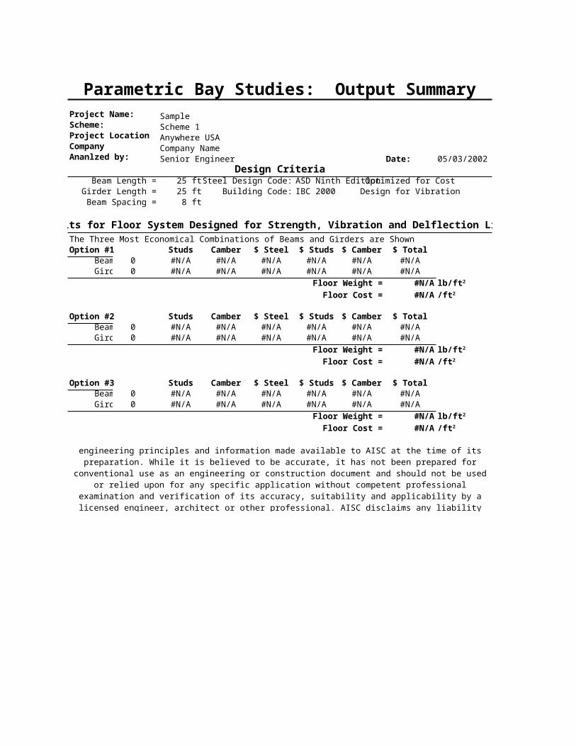
Parametric Bay Studies: Input SummaryProject Name: SampleScheme: Scheme 1Project Location Anywhere USACompany Company NameAnanlzed by: Senior Engineer Date: 05/03/2002

Design Criteria Bay GeometryDesign Code: ASD Ninth Edition Length (beam length) 25 ft

Building Code: IBC 2000 Width (girder length) 25 ftOptimization: Relative Cost # of Deck Spans per Bay 3 Building Use: Office

Steel Yield Strength: 50 ksi Vibration CriteriaDesigned for Vibration Criteria 3

Loads B 0.04 Dead Load (DL) 0 psf a/g Limit (% of g) 0.50%

Superimposed Dead Load (SDL) 20 psf Po 65 lbsLive Load (LL) 40 psf

Allow Live Load Reduction Yes 15%

Construction Live Load (CLL) 20 psf10%

Floor DeckType of Concrete Slab Form Deck Delfection Limits L/D

Type of Construction Unshored Pre-Composite Dead (DL) 0 240 Concrete thickness above deck 3.25 in Live (LL) 0 360

Concrete Weight 115 pcf Superimposed Dead (SDL) 0 360 f'c 3.0 ksi Total Superimposed (LL+SDL) 0 240

Deck Height 2.0 in Total (DL+LL+SDL-Camber) 0 240 Average Rib Width 6.0 in

Rib Spacing 12.0 in Shear Stud Data Stud Diameter 3/4 in

Beam Stud Height 4.0 inMinimum Beam Size ### Stud Yield Strength 60 ksi

Maximum Beam Size 0 Maximum Composite % 90%Camber Allowed Minimum Composite % 25%

Type of Analysis CompositeStud Spacing Limits Deck Direction

Girder Code Limits parallel perp.Minimum Girder Size 0 Longitudinal 4.5 in 3.0 in

Maximum Girder Size 0 Transverse 3.0 in 3.0 inCamber Allowed

Longitudinal 42.0 in 36.0 inType of Analysis Composite

Camber Criteria Cost DataMinimum Camber 0.75 in Structural Steel (A992) 0.25 $/lb

Maximum Camber 2 in Installed Studs 3.00 $/studCamber Increment 0.25 in Camber 2

Maximum Camber in Range 1 15.0 in25 ft Cost per Member in Range 1 15.00 $/member

Maximum Camber in Range 2 1.5 in75% in Cost per Member in Range 2 17.50 $/member

Camber Non-Compact Members Maximum Camber in Range 3 2.0 inCost per Member in Range 3 25.00 $/member

% of Superimposed Dead Load to include for vibration

% of Live Load to include for vibration

D (in)

Minimum Spacing

Maximum Spacing

Minimum Length of Cambered Members

Percent of Dead Load to Camber

This spreadsheet has been prepared by AISC MArketing in accordance with recognized engineering principles and information made available to AISC at the time of its preparation. While it is believed to be accurate, it has not been prepared for conventional use as an engineering or construction document and should not be used or relied upon for any specific application without competent professional examination

and verification of its accuracy, suitability and applicability by a licensed engineer, architect or other professional. AISC disclaims any liability arising from the unauthorized use of the information contained in

this spreadsheet.

1 2 3 4 5 6 7 8 9 10

2 Design Criteria Sample3 Scheme 1

4 Design Code 2 Vibration Analysis 3 Anywhere USA

5 Building Code 4 B 0.04 Company Name

6 ximum Composite % 90% a/g Limit (% of g) 0.50% Senior Engineer

7 inimum Composite % 25% Po 65 lbs 05/03/20028 Optimization 1 Fy 509

10 Delfection Limits11 Pre-Composite12 Dead (DL) 0 240 % of Dead Load to Camber 75%13 Post Composite14 Live (LL) 0 360 building use 115 Superimposed Dead (SDL) 0 36016 site Superimposed (LL+SDL) 0 24017 Total (DL+LL+SDL-Camber) 0 24018 Slab Data19 Load Criteria Deck Height 2.00 2.0020 Dead Load (DL) 0 psf Average Rib Width 6.00 in21 perimposed Dead Load (SDL) 20 psf Rib Spacing 12.00 in22 Live Load (LL) 40 psf Concrete thickness above deck 3.25 in23 allow live load reduction 1 psf f'c 3.00 ksi24 max reduction psf Concrete Weight 115.00 pcf25 Construction Live Load (CLL) 20 psf Stud Yield Strength 60.00 ksi

26 Stud Diameter 3.00 0.75

27 Bay Parameters Stud Height 4.00 in

28 Length (beam length) 25.00 ft Type of Conrete Slab 1.00 Form Deck

29 Width (girder length) 25.00 ft Type of Construction 1.00 Un-Shored30 # of Deck Spans per Bay 3.0031 32 Beam Girder

33 Minimum Beam Size 44 0 Minimum Girder Size 52 0

34 Maximum Beam Size 0 0 Maximum Girder Size 0 0

35 Camber 1 1 Camber 1 136 Type of Analysis 0 Type of Analysis 0

1 2 3 4 5 6 7 8 9 10

D (in) L/D

1 2 3 4 5 6 7 8 2 Structural Steel3 A-992 Steel, cost per Pound $0.254 5 6 ts = 5.25 7 Flat slab=08 Studs 1 3 stud diameter9 Cost per Installed Stud $3.00 Stud spacing: 1 0.75

10 Min Stud Spacing: parallel perpendicular11 Longitudinal 4.5 3 3 3 12 Transverse 3 3 3 3 13 Max Stud Spacing:14 Longitudinal 42 36 24 24 15 camber cost/beam 15 16 r1camber 1 17 Camber

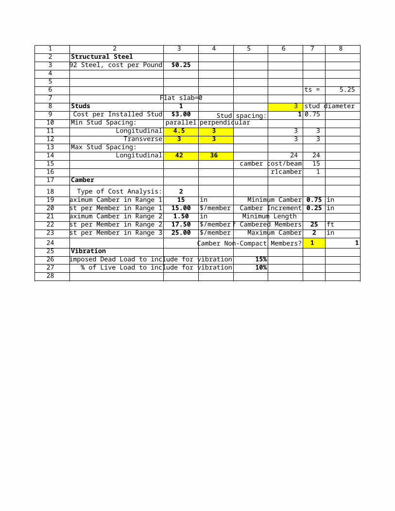
18 Type of Cost Analysis: 219 Maximum Camber in Range 1 15 in Minimum Camber 0.75 in20 Cost per Member in Range 1 15.00 $/member Camber Increment 0.25 in21 Maximum Camber in Range 2 1.50 in Minimum Length22 Cost per Member in Range 2 17.50 $/member of Cambered Members 25 ft23 Cost per Member in Range 3 25.00 $/member Maximum Camber 2 in

24 Camber Non-Compact Members? 1 125 Vibration26 % of Superimposed Dead Load to include for vibration 15%27 % of Live Load to include for vibration 10%28

Parametric Bay Studies: Output Summary

Project Name: SampleScheme: Scheme 1Project Location Anywhere USACompany Company NameAnanlzed by: Senior Engineer Date: 05/03/2002

Design CriteriaBeam Length = 25 ft Steel Design Code: ASD Ninth Edition Optimized for CostGirder Length = 25 ft Building Code: IBC 2000 Design for Vibration

Beam Spacing = 8.3 ft Office

Results for Floor System Designed for Strength and Deflection Limits

Beams Studs Camber $ Steel $ Studs $ Camber $ Total Vibration0 0 0.00" $0 $0 $0 $0 NG0 0 0.00" $0 $0 $0 $0 NG0 0 0.00" $0 $0 $0 $0 NG

Girders Studs Camber $ Steel $ Studs $ Camber $ Total Vibration0 0,,0 0.00" $0 $0 $0 $0 NG0 0,,0 0.00" $0 $0 $0 $0 NG0 0,,0 0.00" $0 $0 $0 $0 NG

Choose Beam: 3 Combined Mode Vibration = OK

Floor Steel Weight = #N/A

Choose Girder: 2 Floor Total Cost = $0.00

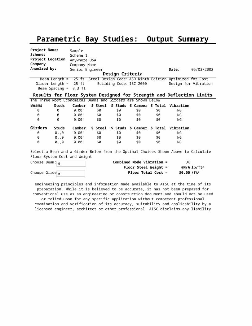
The Three Most Economical Beams and Girders are Shown Below

Select a Beam and a Girder Below from the Optimal Choices Shown Above to Calculate Floor System Cost and Weight

lb/ft2

/ft2

This spreadsheet has been prepared by AISC Marketing in accordance with recognized engineering principles and information made available to AISC at the time of its preparation. While it is believed to be accurate, it has not been prepared for conventional use as an engineering or construction document and should not be used or

relied upon for any specific application without competent professional examination and verification of its accuracy, suitability and applicability by a licensed engineer, architect or other professional. AISC disclaims any

liability arising from the unauthorized use of the information contained in this spreadsheet.

Parametric Bay Studies: Output Summary

Project Name: SampleScheme: Scheme 1Project Location Anywhere USACompany Company NameAnanlzed by: Senior Engineer Date: 05/03/2002

Design CriteriaBeam Length = 25 ft Steel Design Code: ASD Ninth Edition Optimized for CostGirder Length = 25 ft Building Code: IBC 2000 Design for Vibration

Beam Spacing = 8 ft Office

Results for Floor System Designed for Strength, Vibration and Delflection LimitsThe Three Most Economical Combinations of Beams and Girders are ShownOption #1 Studs Camber $ Steel $ Studs $ Camber $ Total Beam 0 #N/A #N/A #N/A #N/A #N/A #N/A Girder 0 #N/A #N/A #N/A #N/A #N/A #N/A

Floor Weight = #N/A

Floor Cost = #N/A

Option #2 Studs Camber $ Steel $ Studs $ Camber $ Total Beam 0 #N/A #N/A #N/A #N/A #N/A #N/A Girder 0 #N/A #N/A #N/A #N/A #N/A #N/A

Floor Weight = #N/A

Floor Cost = #N/A

Option #3 Studs Camber $ Steel $ Studs $ Camber $ Total Beam 0 #N/A #N/A #N/A #N/A #N/A #N/A Girder 0 #N/A #N/A #N/A #N/A #N/A #N/A

Floor Weight = #N/A

Floor Cost = #N/A

lb/ft2

/ft2

lb/ft2

/ft2

lb/ft2

/ft2

This spreadsheet has been prepared by AISC Marketing in accordance with recognized engineering principles and information made available to AISC at the time of its preparation. While it is believed to be accurate, it has not been prepared for conventional use as an engineering or construction document and should not be used or

relied upon for any specific application without competent professional examination and verification of its accuracy, suitability and applicability by a licensed engineer, architect or other professional. AISC disclaims any

liability arising from the unauthorized use of the information contained in this spreadsheet.

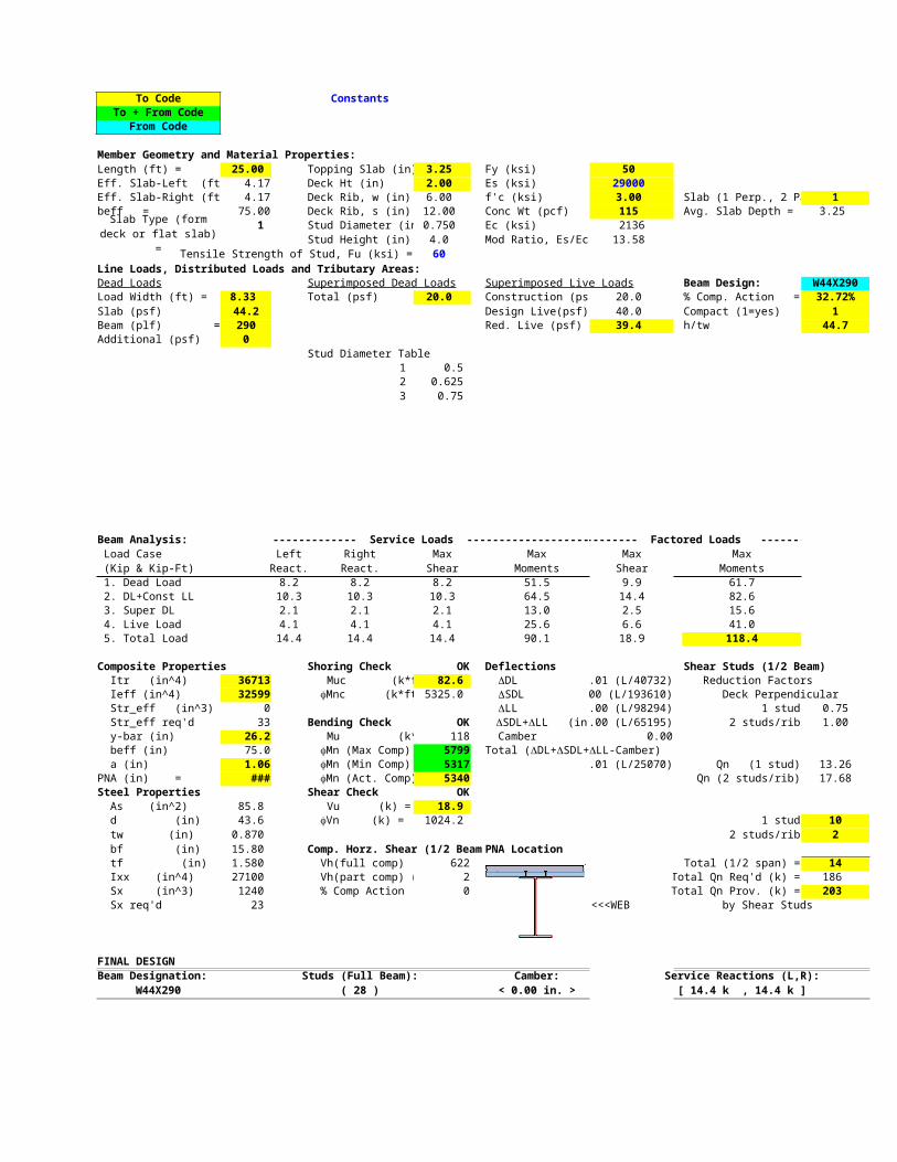
Parametric Bay Studies: LRFD Composite Beam Design

Project Name: SampleScheme: Scheme 1Project Location Anywhere USACompany Company NameAnanlzed by: Senior Engineer Date: 05/03/2002

General Information OfficeSteel Code: LRFD Design for Vibration

Building Code: IBC 2000 Unshored Construction

Span Information Beam Design Load CriteriaSteel Deck+Concrete Weight 44.2 psf

Beam Size Dead Load-No Self Weight (DL) 0 psfBeam Length 25 ft Superimposed Dead Load (SDL) 20 psf

Spacing 8.3 ft Live Load (LL) 40 psf (Reducible)Fy = 50 ksi Construction Live Load (CLL) 20 psf

Composite PropertiesConcrete Thickness 3.25 in Min Comp % 25%

Concrete Unit Weight 115 pcf Max comp % 90%f'c 3.0 ksi #N/A k*ft

Deck Height 2.0 in #N/A k*ftEffective Concrete Width, be #N/A in Y bar (from bottom of steel beam) #N/A in

#N/A k*ft #N/A k*ftCompressive Force in Concrete, C #N/A k PNA #N/A in

Effective Moment of Inertia, Ieff #N/A Transform Moment of Inertia, Itr #N/Astud length 4.0 in stud diameter 3/4 in

stud yield strength 60 ksiStud capacity Number of Studs

Qn (1 Stud per Rib) #N/A k # studs (1 Stud per Rib) #N/AQn (2 Studs per Rib) #N/A k # studs (2 Studs per Rib) #N/A

Total #N/APercent of Full Composite Action #N/A

Line Loads (k/ft)DL SDL LL Red % CLL

#N/A #N/A #N/A #N/A #N/A

ShearMaximum Factored Shear, Vu #N/A k

#N/A k

MomentsCondition Load Combo Mu (k*ft) Phi

Pre Composite 1.2DL+1.6CLL #N/A 0.9 #N/AComposite 1.4(DL+SDL) #N/A 0.85 #N/AComposite 1.2(DL+SDL)+1.6LL #N/A 0.85 #N/A

ReactionsDL Reaction #N/A kips

SDL Reaction #N/A kipsLL reaction #N/A kips

CLL reaction #N/A kipsTotal Reaction #N/A kips

Deflection Camber #N/ADL #N/A in #N/ALL #N/A in #N/A

SDL #N/A in #N/ATotal (DL+LL+SDL-Camber) #N/A in #N/A

Cost per Beam WeightSteel #N/A Total/Beam #N/A lbs

Studs #N/A Steel psf #N/A psfCamber #N/A

Total #N/A #N/A

Vibration

Ec = 2136 ksin (vibration) = 10.06 Modular Ratio for Vibration = Es/(1.35*Ec)

y_bar = #N/A in From Bottom of Effective ConcreteIj = #N/A in4

% sdl = 15%% ll = 10%

wj = #N/A plf#N/A in

fj = #N/A Hz

Ds = #N/A Transformed slab moment of intertia per unit width

Dj = #N/ACj = 2.0 Effective Width CoefficientBj = #N/A in

Contj = 1.5 Continuity Factor for Web Connected BeamsWj = #N/A kipsPo = 65 lbs

Beta = 0.040aj/g = #N/A

Minimum Moment Strength, fMnMaximum Moment Strength, fMn

Full Moment Strength, fMnf Actual Moment Strength, fMn

in4 in4

Shear Strength, fVn

fMn (k*ft)

D/L

/ft2

Dj =

in4/ft

in4/ft

This spreadsheet has been prepared by AISC Marketing in accordance with recognized engineering principles and information made available to AISC at the time of its preparation. While it is believed to be accurate, it has not been prepared for

conventional use as an engineering or construction document and should not be used or relied upon for any specific application without competent professional examination and verification of its accuracy, suitability and applicability by a licensed engineer, architect or other professional. AISC disclaims any liability arising from the unauthorized use of the information contained in this

spreadsheet.

Parametric Bay Studies: LRFD Composite Girder DesignProject Name: SampleScheme: Scheme 1Project Location Anywhere USACompany Company NameAnanlzed by: Senior Engineer Date: 05/03/2002

General Information OfficeSteel Code: LRFD Design for Vibration

Building Code: IBC 2000 Unshored Construction

Span Information: Girder Design Load CriteriaSteel Deck+Concrete Weight 44.2 psf

Girder Size Dead Load-No Self Weight (DL) 0 psfGirder Length 25 ft Superimposed Dead Load (SDL) 20 psf

Spacing 25 ft Live Load (LL) 40 psf (Reducible)Fy = 50 ksi Construction Live Load (CLL) 20 psf

Composite PropertiesConcrete Thickness 3.25 in Min Comp % 25%

Concrete Unit Weight 115 pcf Max comp % 90%f'c 3.0 ksi #N/A k*ft

Deck Height 2.0 in #N/A k*ftEffective Concrete Width, be #N/A in Y bar (from bottom of steel beam) #N/A in

#N/A k*ft #N/A k*ftCompressive Force in Concrete, C #N/A k PNA #N/A in

Effective Moment of Inertia, Ieff #N/A Transform Moment of Inertia, Itr #N/Astud length 4.0 in stud diameter 3/4 in

stud yield strength 60 ksiStud capacity Number of Studs

Qn (1 Stud per Row) #N/A k # studs (1 Stud per Row) #N/AQn (2 Studs per Row) #N/A k # studs (2 Studs per Row) #N/A

# studs in the constant moment region #N/APercent of Full Composite Action #N/A Total #N/A

Point Loads (kips) Located at each Beam ConnectionDL SDL LL Red % CLL

#N/A #N/A #N/A #N/A #N/A

Shear at Girder EndsMaximum Factored Shear, Vu #N/A k

#N/A k

Moments at CenterlineCondition Load Combo Mu (k*ft) Phi

Pre Composite 1.2DL+1.6CLL #N/A 0.9 #N/AComposite 1.4(DL+SDL) #N/A 0.85 #N/AComposite 1.2(DL+SDL)+1.6LL #N/A 0.85 #N/A

ReactionsDL Reaction #N/A kips

SDL Reaction #N/A kipsLL reaction #N/A kips

CLL reaction #N/A kipsTotal Reaction #N/A kips

Deflection Camber #N/ADL #N/A in #N/ALL #N/A in #N/A

SDL #N/A in #N/ATotal (DL+LL+SDL-Camber) #N/A in #N/A

Cost per Beam WeightSteel #N/A Total/Girder #N/A lbs

Studs #N/A Steel psf #N/A psfCamber #N/A

Total #N/A #N/A /ft2

Vibration 3

Ec = 2136 ksin (vibration) = 10.06 Modular Ratio for Vibration = Es/(1.35*Ec)

y_bar = #N/A in From Bottom of Effective ConcreteIg = #N/A in4

% sdl = 15%% ll = 10%wg = #N/A plf

#N/A infg = #VALUE! Hz

Dj = #VALUE! Beam Transformed moment of intertia per unit width

Dg = #N/ACg = 1.8 Effective Width CoefficientBg = #VALUE! in

Contg = 1.0 Continuity Factor for Girders Connected to ColumnsWg = #VALUE! kipsPo = 65 lbs

Beta = 0.040ag/g = #VALUE!

Minimum Moment Strength, fMnMaximum Moment Strength, fMn

Full Moment Strength, fMnf Actual Moment Strength, fMn

in4 in4

Shear Strength, fVn

fMn (k*ft)

D/L

Beam Selected for Vibration Check of Girder

Dg =

in4/ft

in4/ft

This spreadsheet has been prepared by AISC Marketing in accordance with recognized engineering principles and information made available to AISC at the time of its preparation. While it is believed to be accurate, it has not been prepared for conventional use as an

engineering or construction document and should not be used or relied upon for any specific application without competent professional examination and verification of its accuracy, suitability and applicability by a licensed engineer, architect or other professional. AISC disclaims any liability arising from the unauthorized use of the information contained in this spreadsheet.

Parametric Bay Studies: ASD Composite Beam Design

Project Name: SampleScheme: Scheme 1Project Location Anywhere USACompany Company NameAnanlzed by: Senior Engineer Date: 05/03/2002

General Information OfficeSteel Code: ASD Design for Vibration

Building Code: IBC 2000 Unshored Construction

Span Information Beam Design Load CriteriaSteel Deck+Concrete Weight 44.2 psf

Beam Size Dead Load-No Self Weight (DL) 0 psfBeam Length 25 ft Superimposed Dead Load (SDL) 20 psf

Spacing 8 ft Live Load (LL) 40 psf (Reducible)Fy = 50 ksi Construction Live Load (CLL) 20 psf

Composite PropertiesConcrete Thickness 3.25 in Min Comp % 25%

Concrete Unit Weight 115 pcf Max comp % 90%f'c 3.0 ksi

Deck Height 2.0 inEffective Concrete Width, be #N/A in Y bar (from bottom of steel beam) #N/A in

Effective Section Modulus, Seff #N/A Transform Section Modulus, Str #N/A k*ftCompressive Force in Concrete, C #N/A k

Effective Moment of Inertia, Ieff #N/A Transform Moment of Inertia, Itr #N/Astud length 4.0 in stud diameter 3/4 in

stud yield strength 60 ksiStud capacity Number of Studs

Qn (1 Stud per Rib) #N/A k # studs (1 Stud per Rib) #N/AQn (2 Studs per Rib) #N/A k # studs (2 Studs per Rib) #N/A

Total #N/APercent of Full Composite Action #N/A

Line Loads (k/ft)DL SDL LL Red % CLL

#N/A #N/A #N/A #N/A #N/A

ShearMaximum Shear, V #N/A k

Shear Stress #N/A ksiAllowable Shear Stress 20 ksi

MomentsCondition Load Combo M (k*ft) fb Fb

Pre Composite DL+CLL #N/A #N/A 33Mmax/Seff DL+SDL+LL #N/A #N/A 33

Mdl/Sx+Mpost/Seff (DL)+(SDL+LL) #N/A #N/A 45

Concrete StressPost Composite Concrete Stress #N/A ksi

Allowable Concrete Stress 1.35 ksi

ReactionsDL Reaction #N/A kips

SDL Reaction #N/A kipsLL reaction #N/A kips

CLL reaction #N/A kipsTotal Reaction #N/A kips

Deflection Camber #N/ADL #N/A in #N/ALL #N/A in #N/A

SDL #N/A in #N/ATotal (DL+LL+SDL-Camber) #N/A in #N/A

Cost per Beam WeightSteel #N/A Total/Beam #N/A lbs

Studs #N/A Steel psf #N/A psfCamber #N/A

Total #N/A #N/A

Vibration

Ec = 2136 ksin (vibration) = 10.06 Modular Ratio for Vibration = Es/(1.35*Ec)

y_bar = #N/A in From Bottom of Effective ConcreteIj = #N/A in4

% sdl = 15%% ll = 10%

wj = #N/A plf#N/A in

fj = #N/A Hz

Ds = #N/A Transformed slab moment of intertia per unit width

Dj = #N/ACj = 2.0 Effective Width CoefficientBj = #N/A in

Contj = 1.5 Continuity Factor for Web Connected BeamsWj = #N/A kipsPo = 65 lbs

Beta = 0.040aj/g = #N/A

in3

in4 in4

D/L

/ft2

Dj =

in4/ft

in4/ft

This spreadsheet has been prepared by AISC Marketing in accordance with recognized engineering principles and information made available to AISC at the time of its preparation. While it is believed to be accurate, it has not been prepared for

conventional use as an engineering or construction document and should not be used or relied upon for any specific application without competent professional examination and verification of its accuracy, suitability and applicability by a licensed engineer, architect or other professional. AISC disclaims any liability arising from the unauthorized use of the information contained in this

spreadsheet.

Parametric Bay Studies: ASD Composite Girder Design

Project Name: SampleScheme: Scheme 1Project Location Anywhere USACompany Company NameAnanlzed by: Senior Engineer Date: 05/03/2002

General Information OfficeSteel Code: ASD Design for Vibration

Building Code: IBC 2000 Unshored Construction

Span Information Beam Design Load CriteriaSteel Deck+Concrete Weight 44.2 psf

Girder Size Dead Load-No Self Weight (DL) 0 psfGirder Length 25 ft Superimposed Dead Load (SDL) 20 psf

Spacing 25 ft Live Load (LL) 40 psf (Reducible)Fy = 50 ksi Construction Live Load (CLL) 20 psf

Composite PropertiesConcrete Thickness 3.25 in Min Comp % 25%

Concrete Unit Weight 115 pcf Max comp % 90%f'c 3.0 ksi

Deck Height 2.0 inEffective Concrete Width, be #N/A in Y bar (from bottom of steel beam) #N/A in

Effective Section Modulus, Seff #N/A Transform Section Modulus, Str #N/A k*ftCompressive Force in Concrete, C #N/A k

Effective Moment of Inertia, Ieff #N/A Transform Moment of Inertia, Itr #N/Astud length 4.0 in stud diameter 3/4 in

stud yield strength 60 ksiStud capacity Number of Studs

Qn #N/A k # studs (1 Stud per Row) #N/A# studs (2 Studs per Row) #N/A

# studs in the constant moment region #N/APercent of Full Composite Action #N/A Total #N/A

Point Loads (kips) Located at each Beam ConnectionDL SDL LL Red % CLL

#N/A #N/A #N/A #N/A #N/A

ShearMaximum Shear, V #N/A k

Shear Stress #N/A ksiAllowable Shear Stress 20 ksi

Moments at CenterlineCondition Load Combo M (k*ft) fb Fb

Pre Composite DL+CLL #N/A #N/A 33.0Mmax/Seff DL+SDL+LL #N/A #N/A 33.0

Mdl/Sx+Mpost/Seff (DL)+(SDL+LL) #N/A #N/A 45.0

Concrete StressPost Composite Concrete Stress #N/A ksi

Allowable Concrete Stress 1.35 ksi

ReactionsDL Reaction #N/A kips

SDL Reaction #N/A kipsLL reaction #N/A kips

CLL reaction #N/A kipsTotal Reaction #N/A kips

Deflection Camber #N/ADL #N/A in #N/ALL #N/A in #N/A

SDL #N/A in #N/ATotal (DL+LL+SDL-Camber) #N/A in #N/A

Cost per Beam WeightSteel #N/A Total/Beam #N/A lbs

Studs #N/A Steel psf #N/A psfCamber #N/A

Total #N/A #N/A

Vibration 3

Ec = 2136 ksin (vibration) = 10.06 Modular Ratio for Vibration = Es/(1.35*Ec)

y_bar = #N/A in From Bottom of Effective ConcreteIg = #N/A in4

% sdl = 15%% ll = 10%wg = #N/A plf

0.00 infg = #VALUE! Hz

Dj = #VALUE!Beam Transformed moment of intertia per unit width

Dg = #N/ACg = 1.8 Effective Width CoefficientBg = #VALUE! in

Contg = 1.0 Continuity Factor Girders Connected to ColumnsWg = #VALUE! kipsPo = 65 lbs

Beta = 0.040ag/g = #VALUE!

Max ao/g = 0.50%

in3

in4 in4

D/L

/ft2

Beam Selected for Vibration Check of Girder

Dg =

in4/ft

in4/ft

This spreadsheet has been prepared by AISC Marketing in accordance with recognized engineering principles and information made available to AISC at the time of its preparation. While it is believed to be accurate, it has not been prepared for conventional use as an

engineering or construction document and should not be used or relied upon for any specific application without competent professional examination and verification of its accuracy, suitability and applicability by a licensed engineer, architect or other professional. AISC

disclaims any liability arising from the unauthorized use of the information contained in this spreadsheet.

1 2 3 4 5 6 7 8 9 10 11 12 13

Beam Section Selection

Check Sections to be Included in Beam Design

min max ALL NONE ECONOMICAL Custom

1 5 1 1 1 1 1 3 1 2 2 W44 W44X335 0 1 0 0 0 0

3 3 W44 W44X290 1 1 0 0 1 1

4 4 W44 W44X262 1 1 0 0 1 1

5 5 W44 W44X230 1 1 0 0 1 1

6 28 1 1 1 1 1 3 1 7 7 W40 W40X593 0 1 0 0 0 0

8 8 W40 W40X503 0 1 0 0 0 0

9 9 W40 W40X431 0 1 0 0 0 0

10 10 W40 W40X397 0 1 0 0 0 0

11 11 W40 W40X372 0 1 0 0 0 0

12 12 W40 W40X362 0 1 0 0 0 0

13 13 W40 W40X324 0 1 0 0 0 0

14 14 W40 W40X297 0 1 0 0 0 0

15 15 W40 W40X277 0 1 0 0 0 0

16 16 W40 W40X249 0 1 0 0 0 0

17 17 W40 W40X215 0 1 0 0 0 0

18 18 W40 W40X199 0 1 0 0 0 0

19 19 W40 W40X392 0 1 0 0 0 0

20 20 W40 W40X331 0 1 0 0 0 0

21 21 W40 W40X327 0 1 0 0 0 0

22 22 W40 W40X278 0 1 0 0 0 0

23 23 W40 W40X264 0 1 0 0 0 0

24 24 W40 W40X235 0 1 0 0 0 0

25 25 W40 W40X211 0 1 0 0 0 0

26 26 W40 W40X183 1 1 0 0 1 1

27 27 W40 W40X167 1 1 0 0 1 1

28 28 W40 W40X149 1 1 0 0 1 1

29 50 1 1 1 1 1 3 1 30 30 W36 W36X798 0 1 0 0 0 0

31 31 W36 W36X650 0 1 0 0 0 0

32 32 W36 W36X527 0 1 0 0 0 0

33 33 W36 W36X439 0 1 0 0 0 0

34 34 W36 W36X393 0 1 0 0 0 0

35 35 W36 W36X359 0 1 0 0 0 0

36 36 W36 W36X328 0 1 0 0 0 0

37 37 W36 W36X300 0 1 0 0 0 0

38 38 W36 W36X280 0 1 0 0 0 0

39 39 W36 W36X260 0 1 0 0 0 0

40 40 W36 W36X245 0 1 0 0 0 0

41 41 W36 W36X230 0 1 0 0 0 0

42 42 W36 W36X256 0 1 0 0 0 0

43 43 W36 W36X232 0 1 0 0 0 0

44 44 W36 W36X210 0 1 0 0 0 0

45 45 W36 W36X194 0 1 0 0 0 0

46 46 W36 W36X182 0 1 0 0 0 0

Girder Section Selection

Check Sections to be Included in Beam Design

min max ALL NONE ECONOMICAL Custom

1 5 1 1 1 1 1 4 1 2 2 W44 W44X335 1 1 0 0 1 1

3 3 W44 W44X290 1 1 0 0 1 1

4 4 W44 W44X262 1 1 0 0 1 1

5 5 W44 W44X230 1 1 0 0 1 1

6 28 1 1 1 1 1 7 1 7 7 W40 W40X593 0 1 0 0 0 0

8 8 W40 W40X503 0 1 0 0 0 0

9 9 W40 W40X431 0 1 0 0 0 0

10 10 W40 W40X397 0 1 0 0 0 0

11 11 W40 W40X372 0 1 0 0 0 0

12 12 W40 W40X362 0 1 0 0 0 0

13 13 W40 W40X324 0 1 0 0 0 0

14 14 W40 W40X297 0 1 0 0 0 0

15 15 W40 W40X277 0 1 0 0 0 0

16 16 W40 W40X249 0 1 0 0 0 0

17 17 W40 W40X215 0 1 0 0 0 0

18 18 W40 W40X199 0 1 0 0 0 0

19 19 W40 W40X392 0 1 0 0 0 0

20 20 W40 W40X331 0 1 0 0 0 0

21 21 W40 W40X327 0 1 0 0 0 0

22 22 W40 W40X278 1 1 0 0 1 1

23 23 W40 W40X264 1 1 0 0 1 1

24 24 W40 W40X235 1 1 0 0 1 1

25 25 W40 W40X211 1 1 0 0 1 1

26 26 W40 W40X183 1 1 0 0 1 1

27 27 W40 W40X167 1 1 0 0 1 1

28 28 W40 W40X149 1 1 0 0 1 1

29 50 1 1 1 1 1 5 1 30 30 W36 W36X798 0 1 0 0 0 0

31 31 W36 W36X650 0 1 0 0 0 0

32 32 W36 W36X527 0 1 0 0 0 0

33 33 W36 W36X439 0 1 0 0 0 0

34 34 W36 W36X393 0 1 0 0 0 0

35 35 W36 W36X359 0 1 0 0 0 0

36 36 W36 W36X328 0 1 0 0 0 0

37 37 W36 W36X300 0 1 0 0 0 0

38 38 W36 W36X280 0 1 0 0 0 0

39 39 W36 W36X260 0 1 0 0 0 0

40 40 W36 W36X245 0 1 0 0 0 0

41 41 W36 W36X230 0 1 0 0 0 0

42 42 W36 W36X256 0 1 0 0 0 0

43 43 W36 W36X232 0 1 0 0 0 0

44 44 W36 W36X210 0 1 0 0 0 0

45 45 W36 W36X194 0 1 0 0 0 0

46 46 W36 W36X182 1 1 0 0 1 1

WorkSheet "Grider"Input from WorkSheet into Code

Variable Name row column Column multiple Celllength 6 3 C *12 C6loadwidth 15 3 C *12 C15w_deck 16 3 C /144000 C16w_girder 17 3 C /12000 C17dl 18 3 C /144000 C18I_full 42 3 C C42I_effective 43 3 C C43y_bar 46 3 C C46a_conc 48 3 C C48topping 6 6 F F6ht_deck 7 6 F F7sdl 15 6 F /144000 F15M_construction 42 6 F *12 F42phi_Mn_max 47 6 F *12 F47phi_Mn_min 48 6 F *12 F48phi_Mn 49 6 F *12 F49Vu 51 6 F F51fy_steel 6 9 I I6E_steel 7 9 I I7fc_conc 8 9 I I8density_conc 9 9 I I9ll 17 9 I /144000 I17Mu 39 11 K *12 K39orientation_slab 8 12 L L8comp_percent 15 12 L L15num_studs_1 52 12 L L52num_studs_2 53 12 L L53num_studs 55 12 L L55C_conc 57 12 L L57def_dl 67 23 W W67camber 69 23 W W69def_sdl 67 24 X X67def_ll 67 25 Y Y67area_steel 5 33 AG AG5depth_steel 6 33 AG AG6tw_steel 7 33 AG AG7bf_steel 8 33 AG AG8tf_steel 9 33 AG AG9I_steel 10 33 AG AG10S_steel 11 33 AG AG11Z_steel 12 33 AG AG12phi_Mn_bare 13 33 AG *12 AG13be_conc 9 39 AM AM9max_C_studs 9 43 AQ AQ9

WorkSheet "Girder"Input from Code into Worksheet

phi_Mn_max 47 6 F /12 F47phi_Mn_min 48 6 F /12 F48

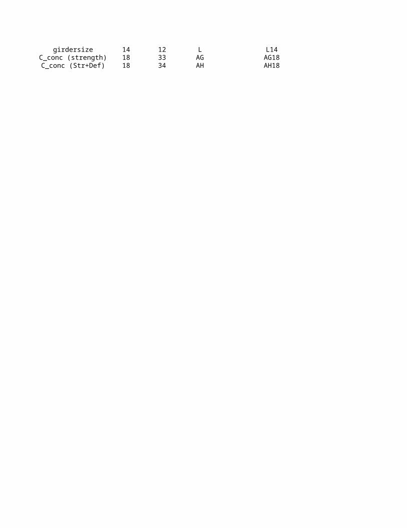
girdersize 14 12 L L14C_conc (strength) 18 33 AG AG18C_conc (Str+Def) 18 34 AH AH18

To Code ConstantsTo + From Code

From Code

Member Geometry and Material Properties:Length (ft) = 25.00 Topping Slab (in) = 3.25 Fy (ksi) = 50 Eff. Slab-Left (ft) = 4.17 Deck Ht (in) = 2.00 Es (ksi) = 29000 Eff. Slab-Right (ft) 4.17 Deck Rib, w (in) = 6.00 f'c (ksi) = 3.00 Slab (1 Perp., 2 Para.) : 1beff = 75.00 Deck Rib, s (in) = 12.00 Conc Wt (pcf) = 115 Avg. Slab Depth = 3.25

1 Stud Diameter (in)= 0.750 Ec (ksi) = 2136Stud Height (in) = 4.0 Mod Ratio, Es/Ec= 13.58

Tensile Strength of Stud, Fu (ksi) = 60 Line Loads, Distributed Loads and Tributary Areas:Dead Loads Superimposed Dead Loads Superimposed Live Loads Beam Design: W44X290Load Width (ft) = 8.33 Total (psf) = 20.0 Construction (psf) = 20.0 % Comp. Action = 32.72%Slab (psf) = 44.2 Design Live(psf) = 40.0 Compact (1=yes) 1Beam (plf) = 290 Red. Live (psf) = 39.4 h/tw 44.7Additional (psf) = 0

Stud Diameter Table1 0.5 2 0.625 3 0.75

Beam Analysis: ------------------------ Service Loads ------------------------------ --------- Factored Loads --------- Load Case Left Right Max Max Max Max (Kip & Kip-Ft) React. React. Shear Moments Shear Moments 1. Dead Load 8.2 8.2 8.2 51.5 9.9 61.7 2. DL+Const LL 10.3 10.3 10.3 64.5 14.4 82.6 3. Super DL 2.1 2.1 2.1 13.0 2.5 15.6 4. Live Load 4.1 4.1 4.1 25.6 6.6 41.0 5. Total Load 14.4 14.4 14.4 90.1 18.9 118.4

Composite Properties Shoring Check OK Deflections Shear Studs (1/2 Beam) Itr (in^4) = 36713 Muc (k*ft) = 82.6 0.01 (L/40732) Reduction Factors Ieff (in^4) = 32599 5325.0 0.00 (L/193610) Deck Perpendicular Str_eff (in^3) = 0 0.00 (L/98294) 1 stud 0.75 Str_eff req'd = 33 Bending Check OK 0.00 (L/65195) 2 studs/rib 1.00 y-bar (in) = 26.2 Mu (k*ft) = 118 Camber (in) = 0.00 beff (in) = 75.0 5799 a (in) = 1.06 5317 (in) = 0.01 (L/25070) Qn (1 stud) 13.26PNA (in) = ### 5340 Qn (2 studs/rib) 17.68Steel Properties Shear Check OK As (in^2) = 85.8 Vu (k) = 18.9 d (in) = 43.6 1024.2 1 stud 10 tw (in) = 0.870 2 studs/rib 2 bf (in) = 15.80 Comp. Horz. Shear (1/2 Beam) PNA Location tf (in) = 1.580 Vh(full comp) (k) = 622 Total (1/2 span) = 14 Ixx (in^4) = 27100 Vh(part comp) (k) = 2 Total Qn Req'd (k) = 186 Sx (in^3) = 1240 % Comp Action = 0 Total Qn Prov. (k) = 203 Sx req'd = 23 <<<WEB by Shear Studs

FINAL DESIGNBeam Designation: Studs (Full Beam): Camber: Service Reactions (L,R):

W44X290 ( 28 ) < 0.00 in. > [ 14.4 k , 14.4 k ]

Slab Type (form deck or flat slab) =

DDL (in) = fMnc (k*ft) = DSDL (in) =

DLL (in) = DSDL+DLL (in) =

fMn (Max Comp) = Total (DDL+DSDL+DLL-Camber) fMn (Min Comp) = fMn (Act. Comp) =

fVn (k) =

To Code ConstantsTo + From Code

From Code

Member Geometry and Material Properties:Length (ft) = 25.00 Topping Slab (in) = 3.25 Fy (ksi) = 50 Eff. Slab-Left (ft) = 12.50 Deck Ht (in) = 2.00 Es (ksi) = 29000 Eff. Slab-Right (ft) 12.50 Deck Rib, wr (in) = 6.00 f'c (ksi) = 3.00 Slab (1 Perp., 2 Para.) : 2beff = 75.00 Deck Rib, s (in) = 12.00 Conc Wt (pcf) = 115 Avg. Slab Depth = 4.25 Slab Type = 1 Stud Diameter (in)= 0.750 Ec (ksi) = 2136

Stud Height (in) = 4.0 Mod Ratio, Es/Ec= 13.58 Tensile Strength of Stud, Fu (ksi) = 60

Line Loads, Distributed Loads and Tributary Areas:Dead Loads Superimposed Dead Loads Superimposed Live Loads Beam Design: W44X335Load Width (ft) = 25.00 Total (psf) = 20.0 Construction (psf) = 20.0 % Comp. Action = 30.0%Slab (psf) = 44.2 Design Live(psf) = 40.0 Compact (1=yes) 1Beam (plf) = 335 Red. Live (psf) = 27.0 h/tw 38.1Additional (psf) = 0

Stud Diameter Table1 0.5 2 0.625 3 0.75

Beam Analysis: ------------------------ Service Loads ------------------------------ --------- Factored Loads --------- Load Case Left Right Max Max Max Max (Kip & Kip-Ft) React. React. Shear Moments Shear Moments 1. Dead Load 19.0 19.0 19.0 177.8 22.8 213.3 2. Const LL 6.0 24.3 24.3 60.0 34.0 309.3 3. Super DL 3.0 3.0 3.0 30.0 3.6 36.0 4. Live Load 12.0 12.0 12.0 120.0 19.2 192.0 5. Total Load 34.0 34.0 34.0 327.8 45.6 441.3

Composite Properties Shoring Check OK Deflections Shear Studs (1/2 Beam) Itr (in^4) = 43099 Muc (k*ft) = 309.3 0.01 (L/21368) Reduction Factors Ieff (in^4) = 38672 6075.0 0.00 (L/76561) Str_eff (in^3) = 0 0.01 (L/56774) Str_eff req'd = 119 Bending Check OK 0.01 (L/32600) y-bar (in) = 26.8 Mu (k*ft) = 441 Camber (in) = 0.00 beff (in) = 75.0 7034 a (in) = 1.29 6158 (in) = 0.02 (L/12907) Qn 17.68PNA (in) = ### 6159Steel Properties Shear Check OK As (in^2) = 98.3 Vu (k) = 45.6 d (in) = 44.0 1211.8 # Studs One/Row 30 tw (in) = 1.020 # Studs Two/Row 0 bf (in) = 16.00 Comp. Horz. Shear (1/2 Beam) PNA Location tf (in) = 1.770 Vh(full comp) (k) = 622 TOTAL # of Studs 30 Ixx (in^4) = 31100 Vh(part comp) (k) = 2 Qn Req'd (k) = 244 Sx (in^3) = 1410 % Comp Action = 0 Qn Prov. (k) = 248 Sx req'd = 22

FINAL DESIGNBeam Designation: Studs (Full Beam): Camber: Service Reactions (L,R):

W44X335 ( 60 ) < 0.00 in. > [ 34.0 k , 34.0 k ]

DDL (in) = fMnc (k*ft) = DSDL (in) =

DLL (in) = DSDL+DLL (in) =

fMn (Max Comp) = Total (DDL+DSDL+DLL-Camber) fMn (Min Comp) = fMn (Act. Comp) =

fVn (k) =

by Shear Studs bewtween Max Mom and

Zero Mom

To Code ConstantsTo + From Code

From Code

Member Geometry and Material Properties:Length (ft) = 25.00 Topping Slab (in) = 3.25 Fy (ksi) = 50 Eff. Slab-Left (ft) = 4.17 Deck Ht (in) = 2.00 Es (ksi) = 29000 Eff. Slab-Right (ft) 4.17 Deck Rib, w (in) = 6.00 f'c (ksi) = 3.00 Slab (1 Perp., 2 Para.) : 1beff = 75.00 Deck Rib, s (in) = 12.00 Conc Wt (pcf) = 115 Avg. Slab Depth = 3.25 Slab Type = 1 Stud Diameter (in)= 0.750 Ec (ksi) = 2136

Stud Height (in) = 4.0 Mod Ratio, Es/Ec= 13.58 Tensile Strength of Stud, Fu (ksi) = 60

Line Loads, Distributed Loads and Tributary Areas:Dead Loads Superimposed Dead Loads Superimposed Live Loads Beam Design: W44X290Load Width (ft) = 8.33 Total (psf) = 20.0 Construction (psf) = 20.0 % Comp. Action = 13%Slab (psf) = 44.2 Design Live(psf) = 40.0 Compact (1=yes) 1Beam (plf) = 290 Red. Live (psf) = 39.4 Additional (psf) = 0

Beam Analysis: ------------------------ Service Loads ------------------------------ --------- Factored Loads --------- Load Case Left Right Max Max Max Max (Kip & Kip-Ft) React. React. Shear Moments Shear Moments 1. Dead Load 8.2 8.2 8.2 51.5 9.9 61.7 2. DL+Const LL 10.3 10.3 10.3 64.5 14.4 82.6 3. Super DL 2.1 2.1 2.1 13.0 2.5 15.6 4. Live Load 4.1 4.1 4.1 25.6 6.6 41.0 5. Total Load 14.4 14.4 14.4 90.1 18.9 118.4

Composite Properties Shoring Check OK Deflections Shear Studs (1/2 Beam) Itr (in^4) = 36713 Muc (k*ft) = 82.6 0.01 (L/40732) Reduction Factors Ieff (in^4) = 30583 5325.0 0.00 (L/181639) Deck Perpendicular Str_eff (in^3) = 0 0.00 (L/92217) 1 stud 0.75 Str_eff req'd = 33 Bending Check OK 0.00 (L/61164) 2 studs/rib 1.00 y-bar (in) = 26.2 Mu (k*ft) = 118 Camber (in) = 0.00 beff (in) = 75.0 1865 a (in) = 0.43 1519 (in) = 0.01 (L/24450) Qn (1 stud) 7.42

5127 Qn (2 studs/rib) 9.89Steel Properties Shear Check OK As (in^2) = 85.8 Vu (k) = 18.9 d (in) = 43.6 1024.2 1 stud 11 tw (in) = 0.870 2 studs/rib 0 bf (in) = 15.80 Comp. Horz. Shear (1/2 Beam) PNA Location tf (in) = 1.580 Vh(full comp) (k) = 622 Total (1/2 span) = 11 Ixx (in^4) = 27100 Vh(part comp) (k) = 1 Total Qn Req'd (k) = 78 Sx (in^3) = 1240 % Comp Action = 0 Total Qn Prov. (k) = 82 Sx req'd = 23 <<<WEB by Shear Studs

FINAL DESIGNBeam Designation: Studs (Full Beam): Camber: Service Reactions (L,R):

W44X290 ( 22 ) < 0.00 in. > [ 14.4 k , 14.4 k ]

DDL (in) = fMnc (k*ft) = DSDL (in) =

DLL (in) = DSDL+DLL (in) =

fMn (Max Comp) = Total (DDL+DSDL+DLL-Camber) fMn (Min Comp) = fMn (Act. Comp) =

fVn (k) =

To Code ConstantsTo + From Code

From Code

Member Geometry and Material Properties:Length (ft) = 25.00 Topping Slab (in) = 3.25 Fy (ksi) = 50 Eff. Slab-Left (ft) = 12.50 Deck Ht (in) = 2.00 Es (ksi) = 29000 Eff. Slab-Right (ft) 12.50 Deck Rib, wr (in) = 6.00 f'c (ksi) = 3.00 Slab (1 Perp., 2 Para.) : 2beff = 75.00 Deck Rib, s (in) = 12.00 Conc Wt (pcf) = 115 Avg. Slab Depth = 4.25 Slab Type = 1 Stud Diameter (in)= 0.750 Ec (ksi) = 2136

Stud Height (in) = 4.0 Mod Ratio, Es/Ec= 13.58 Tensile Strength of Stud, Fu (ksi) = 60

Line Loads, Distributed Loads and Tributary Areas:Dead Loads Superimposed Dead Loads Superimposed Live Loads Beam Design: W44X335Load Width (ft) = 25.00 Total (psf) = 20.0 Construction (psf) = 20.0 % Comp. Action = 13%Slab (psf) = 44.2 Design Live(psf) = 40.0 Compact (1=yes) 1Beam (plf) = 335 Red. Live (psf) = 27.0 Additional (psf) = 0

Beam Analysis: ------------------------ Service Loads ------------------------------ --------- Factored Loads --------- Load Case Left Right Max Max Max Max (Kip & Kip-Ft) React. React. Shear Moments Shear Moments 1. Dead Load 31.0 31.0 31.0 454.8 37.2 545.7 2. DL+Const LL 24.3 24.3 24.3 151.6 34.0 636.7 3. Super DL 4.5 4.5 4.5 67.5 5.4 81.0 4. Live Load 22.5 22.5 22.5 337.5 36.0 540.0 5. Total Load 58.0 58.0 58.0 859.8 78.6 1166.7

Composite Properties Shoring Check OK Deflections Shear Studs (1/2 Beam) Itr (in^4) = 43099 Muc (k*ft) = 636.7 0.01 (L/21368) Reduction Factors Ieff (in^4) = 36120 6075.0 0.00 (L/71508) Str_eff (in^3) = 0 0.01 (L/53026) Str_eff req'd = 313 Bending Check OK 0.01 (L/30448) y-bar (in) = 26.8 Mu (k*ft) = 1167 Camber (in) = 0.00 beff (in) = 75.0 1651 a (in) = 0.57 1309 (in) = 0.02 (L/12556) Qn 9.89

5918Steel Properties Shear Check OK As (in^2) = 98.3 Vu (k) = 78.6 d (in) = 44.0 1211.8 # Studs One/Row 24 tw (in) = 1.020 # Studs Two/Row 0 bf (in) = 16.00 Comp. Horz. Shear (1/2 Beam) PNA Location tf (in) = 1.770 Vh(full comp) (k) = 622 TOTAL # of Studs 24 Ixx (in^4) = 31100 Vh(part comp) (k) = 1 Qn Req'd (k) = 102 Sx (in^3) = 1410 % Comp Action = 0 Qn Prov. (k) = 109 Sx req'd = 55 <<<WEB

FINAL DESIGNBeam Designation: Studs (Full Beam): Camber: Service Reactions (L,R):

W44X335 ( 48 ) < 0.00 in. > [ 58.0 k , 58.0 k ]

DDL (in) = fMnc (k*ft) = DSDL (in) =

DLL (in) = DSDL+DLL (in) =

fMn (Max Comp) = Total (DDL+DSDL+DLL-Camber) fMn (Min Comp) = fMn (Act. Comp) =

fVn (k) =

by Shear Studs bewtween Max Mom and

Zero Mom


Recommended