Grid InterfacingMax A Parker, Li Ran, Senior Member, IEEE, and Stephen J Finney
Abstract—Modular generator and converter topologies arebeing pursued for large offshore wind turbines to achieve faulttolerance and high reliability. A centralized controller presentsa single critical point of failure which has prevented a trulymodular and fault tolerant system from being obtained. Thisstudy analyses the inverter circuit control requirements duringnormal operation and grid fault ride-through, and proposes adistributed controller design to allow inverter modules to operateindependently of each other. All the modules independentlyestimate the grid voltage magnitude and position, and themodules are synchronised together over a CAN bus. The CANbus is also used to interleave the PWM switching of the modulesand synchronise the ADC sampling. The controller structure andalgorithms are tested by laboratory experiments with respect tonormal operation, initial synchronization to the grid, module faulttolerance and grid fault ride-through.
Index Terms—Distributed control, modular generator, multi-level inverter, PWM interleaving, phaselock loop, estimation, faulttolerance, current control, wind turbine, CAN bus
I. INTRODUCTION
OFFSHORE wind power is set to become an increasingly
important source of energy, and the economics of off-
shore wind are driving the need to develop larger wind tur-
bines, but difficulty of access for repair means that reliability
is of critical importance in minimising operational costs [1].
As the gearbox on the larger turbines is a significant source
of downtime, due to the time and equipment required for
replacement, direct-drive turbines which eliminate the gearbox
could offer greatly increased turbine availability and lower
maintenance costs [2].
Existing direct-drive turbines have been found to suffer
higher failure rates for the generator and fully-rated power
electronic converter than the geared equivalent, and this com-
bined with the higher initial cost has lead to a higher total
cost of ownership for onshore use [3]. However, it has also
Manuscript received June 15, 2011. Accepted for publication January 6,2012.
Max A Parker was with the School of Engineering, Durham University andis now with the Department of Electrical and Electronic Engineering, Uni-versity of Strathclyde, Royal College Building, 204 George Street, Glasgow,UK, G1 1XW (e-mail: [email protected])
Li Ran is with the School of Engineering, Durham University, South Road,Durham, UK, DH1 3LE (e-mail: [email protected])
Stephen J Finney is with the Department of Electrical and ElectronicEngineering, University of Strathclyde.
been suggested that the direct drive design has the greatest
scope for reliability improvements [2], and for offshore use,
the difficulty of access could tip the economic balance in
favour of direct-drive if the availability can be improved. Fault
tolerance – the ability for the turbine to continue functioning
at reduced power when part of the generator or converter has
failed – would increase the turbine availability, and is much
easier to achieve on a generator or converter than on a gearbox.
Larger turbines are also leading to increased interest in
multilevel converters, to increase the generator voltage and
reduce the output voltage distortion for a given switching
frequency [4]–[9]. The converter usually proposed is the 3-
level diode-clamped converter, producing a 3.3kV output with
4500V switching devices [6], [7], [9]. A larger number of
levels would reduce the output voltage distortion, reducing
the size of the output filter and allowing the use of cheaper
switching devices with a lower voltage rating for the same
output voltage [5]. Alternatively, a higher output voltage could
be achieved in order to eliminate the grid coupling transformer
[10], [11]. However it is difficult to control the separate DC
link voltages on a diode-clamped converter with more than
3 levels [6], [12]. Hybrid multilevel converter designs have
been proposed to improve the DC voltage control, but are
complicated designs with many components [5].
A significant criticism of multilevel inverters, particularly
those with a large number of levels, is that the increased
component count will increase the failure rate of the converter.
However, it has also been shown that a multilevel inverter
featuring fault tolerance will have a significantly greater re-
liability, greater than that of a conventional 2-level inverter
[13]–[15].
Of the main multilevel converter designs, the cascaded H-
bridge inverter has the lowest component count for a given
number of levels, and does not suffer from DC-link voltage
balancing issues [10], [12]. It is also simple to design an
inverter constructed from a large number of identical modules,
which can reduce costs through mass production of modules.
Fault tolerance is achieved by designing the inverter to be
tolerant of module faults [13], [14]. The main disadvantage
with this type of inverter is that it requires a large number
of isolated voltage sources to supply the individual modules,
which are supplied by an expensive multi-winding transformer
in commercial implementations [13].
The type of large multipole generator used in direct drive
wind turbines can easily be wired with many individual coils,
which can be used to supply the individual modules of the
2
converter. A fault tolerant modular cascaded multilevel inverter
has been designed [10], the structure of which is shown
in Fig.1a, where each output phase consists of a string of
modules, shown in Fig.1b. Coils are connected to the modules
through boost rectifiers, and fuses are used to protect the coils
from high currents in the event of a short circuit failure of the
module semiconductors. The boost rectifiers are controlled by
a microcontroller-based controller on each module to achieve a
sinusoidal coil current, and the current magnitude is controlled
to regulate the module DC-link voltage [16].
# a1
# a2
# a3
# an
# b1
# b2
# b3
# bn
# c1
# c2
# c3
# cn
Convertermodules
Coils
Gridcoupling
inductor
Vaout
Vbout
Vcout
(a)
Boost rectifiers DC link H-bridge
Coils, with 90°phase shift
Bypassswitch
To othermodules
(b)
Fig. 1. Structure of the proposed grid interface converter. (a) Overallconverter structure for three-phase output. (b) Structure of an individualconverter module.
Generator designs exist where the coils are non-overlapping,
potentially resulting in low mutual inductance between them
[17], [18]. Connecting sets of coils through separate converter
modules allows tolerance of coil faults, as the low mutual
inductance means that a short circuit in one coil should have
a minimal effect on the adjacent coils, and can be cut off by
fusage [19]. Hybrid designs also exist in which a low speed
multi-pole generator is driven through a single stage gearbox,
resulting in a cheaper and lighter generator compared to truly
direct drive [20], and these could be connected in the same
way.
While existing implementations of such an inverter, includ-
ing previous implementations of the design used in this project
[10], can be made tolerant of power electronics faults, they
rely on a central controller. The controller either provides
the module switching pulses directly, or provides a timing
signal synchronised to the grid voltage, from which the module
controller can derive the switching pulses for the H-bridge
[21]. The use of a central controller represents a single critical
point of failure for the converter, and the failure rate of control
electronics within wind turbines has been found to be similar
to that of the power electronic converter [2]. A distributed
control system, which replaces the central controller for both
switching control and tracking the grid voltage, is desirable for
a more fault tolerant converter, and has not been documented
for an inverter based on series-connected modules. Such a
control system is described in this paper.
Parallel connection of voltage source converters, using
either a DC or AC bus, is common in power supply or
distributed generation applications, to achieve redundancy and
improved current capacity and harmonic performance. Dis-
tributed control systems exist using both wired and wireless
synchronisation methods, to achieve current sharing between
converters and interleave the switching to reduce the cur-
rent harmonics [22]–[25]. However, the parallel connection
allows each module to sense the bus voltage, and the current
controllers operate independently, and the interleaving of the
module switching can be carried out at a lower bandwidth as
the stability of each current controller is not affected by the
level of interleaving.
In the proposed converter, the modules are connected in
series, meaning that they cannot detect the AC bus voltage,
and they share the same current, requiring a distributed current
controller structure which has not previously been described in
literature. The performance of a distributed current controller
is dependent on the interleaving of the module switching
waveforms, as bad interleaving will lead to a significant
voltage distortion, leading to current distortion which could
cause instability in the current controller. For this reason, a
wired communication link is used to allow the modules to
synchronise with each other in the fastest and most accurate
way, although this represents a single point of failure for the
system, which is undesirable. It would be possible to provide a
second redundant communications bus, but this would increase
the cost.
For ease of implementation, the 3-phase inverter has been
designed around having the neutral point grounded, allowing
each output phase to be considered as a separate single phase
inverter. In the event of the failure of a module, a switch
is activated to bypass the module, which is triggered by the
loss of a control signal from the module controller. The total
output voltage of the inverter will be reduced, so the output
voltages of the remaining modules must be quickly raised
to compensate and the switching instances re-calculated to
remove the distortion in the output waveform. This has been
demonstrated on a small scale test system [16]. In this system,
the number of module faults that can be tolerated depends
on the amount by which the module DC-link voltages can be
raised. Allowing the neutral point position to shift could allow
tolerance to a greater number of module faults with a smaller
DC-link voltage rise [13], [26].
Two earlier papers, [10] and [16], described the fundamental
configuration of the system, and its control during normal
power tracking and for fault tolerance. This paper intends to
show the distributed control characteristics which have not yet
been seen in wind turbines. As well as operation in normal
conditions, operation during grid faults will also be considered,
this being traditionally difficult to fulfil.
3
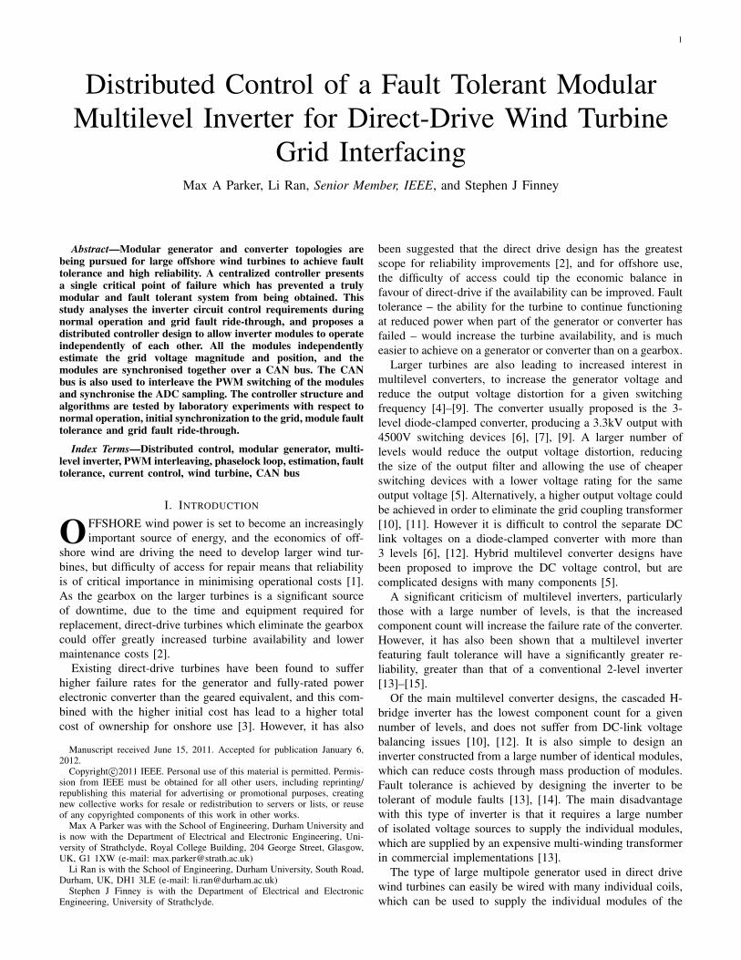
II. GRID FAULT RIDE-THROUGH CONSIDERATIONS
Grid faults will cause a voltage dip viewed at the wind
turbine terminals, and the grid codes of different countries
place requirements on what level of voltage dip the turbine
must ride through without disconnecting. The low voltage
ride-through requirements of the UK grid code are shown in
Fig.2 for the first 3 seconds. The turbine must also further
ride through for 3 minutes at 85% of nominal voltage and
indefinitely at 90% of nominal voltage [27]. The grid codes
of other countries are similar, with some requiring the turbine
to ride through brief voltage dips to zero volts at the turbine
terminals.
Duration (s)
% o
f n
om
ina
l g
rid
vo
lta
ge
0 0.5 1 1.5 2 2.5 30
20
40
60
80
100
Remain Connected
Allowed to disconnect
Fig. 2. Voltage dip ridethrough requirements from UK grid code
These requirements apply for both symmetrical and asym-
metrical faults. As the test rig for this research only features
a single phase string of modules, the response of other phases
cannot be represented, and so only faults affecting that or all
phases equally will be considered. This is sufficient because
the output phases do not share any DC-link capacitors in the
modules.
In a conventional controller for a grid-connected inverter
[28], the grid voltage is measured and a phaselock-loop (PLL)
is used to derive a reference value for the instantaneous grid
voltage magnitude and angle, V̂g and θ̂, assuming that the
grid voltage is of the form vg = Vg sin θ. The inverter output
current is regulated in the rotating reference frame aligned to
θ̂, using a proportional-integral (PI) controller to vary the duty
cycle of the inverter. The output of the current controller is
added to a feedforward voltage, which is the voltage calculated
to achieve the desired current in the steady state, based on V̂g
and θ̂.
When a grid fault occurs, V̂g will take time to react to
the drop in the grid voltage due to the dynamics of the
voltage reference loop, and an incorrect feedforward voltage
will be calculated and applied. The current controller is able
to prevent the sudden surge of reactive power which would
occur, and which would otherwise exceed the thermal limits
of the switching devices. V̂g should then adjust to the new grid
voltage, so the correct feedforward voltage is calculated. Four
aspects of the proposed distributed controller mean that this
approach is difficult to implement:
• The low distortion in the inverter voltage waveform
means that the inverter only requires a small grid coupling
inductor to comply with harmonic limits. Therefore the
current will rise rapidly in response to a drop in grid
voltage, requiring a fast controller to keep the current
within safe limits.
• If a PI controller is used to regulate the current in
each module, then the values of the integrators must be
synchronised between modules so that they all behave
identically. For a sufficiently fast controller, a communi-
cations link with an extremely high bandwidth and low
latency is required between modules, increasing the cost
and processing overhead.
• As the modules are cascaded, they will not be able to
directly measure the grid voltage, so an observer system
must be used, which will use the inverter current to
estimate the voltage.
• If a current controller is not used, then the current will be
controlled by the feedforward voltage, and the bandwidth
of the controller would depend on the speed of the grid
voltage tracking. As the grid voltage references must
be synchronised between modules, a high bandwidth
communications link between modules would still be
required to limit the current.
It is proposed that a proportional controller be used in each
module to limit the current during grid faults, and will operate
in the stationary reference frame, with a sinusoidal reference
current. This will operate independently on all modules, and
will not require synchronisation between modules. The current
will be controlled in normal operation using a feedforward
voltage based on reference values of the grid voltage angle and
magnitude, calculated on each module by an observer system
and synchronised between modules using a communications
link. As the initial current limiting is not dependent on the
bandwidth of the communications link, a lower bandwidth link
can be used.
The inverter controller must also be able to continue track-
ing the grid voltage angle with the reduced magnitude during
a fault. The reduced grid voltage, and the thermal limits on
the inverter current, will limit the amount of real power that
can be exported by the turbine. If the turbine is operating at a
high output power, the sudden reduction in power will cause
the DC-link voltage to rise, and the DC-link voltage controller
will need to quickly react to reduce the input power from the
rectifiers. The DC-link voltage controller has been described
in [16], and the controller bandwidth is limited as the DC-link
voltage contains significant ripple at twice the grid frequency,
which must be avoided in the coil current control.
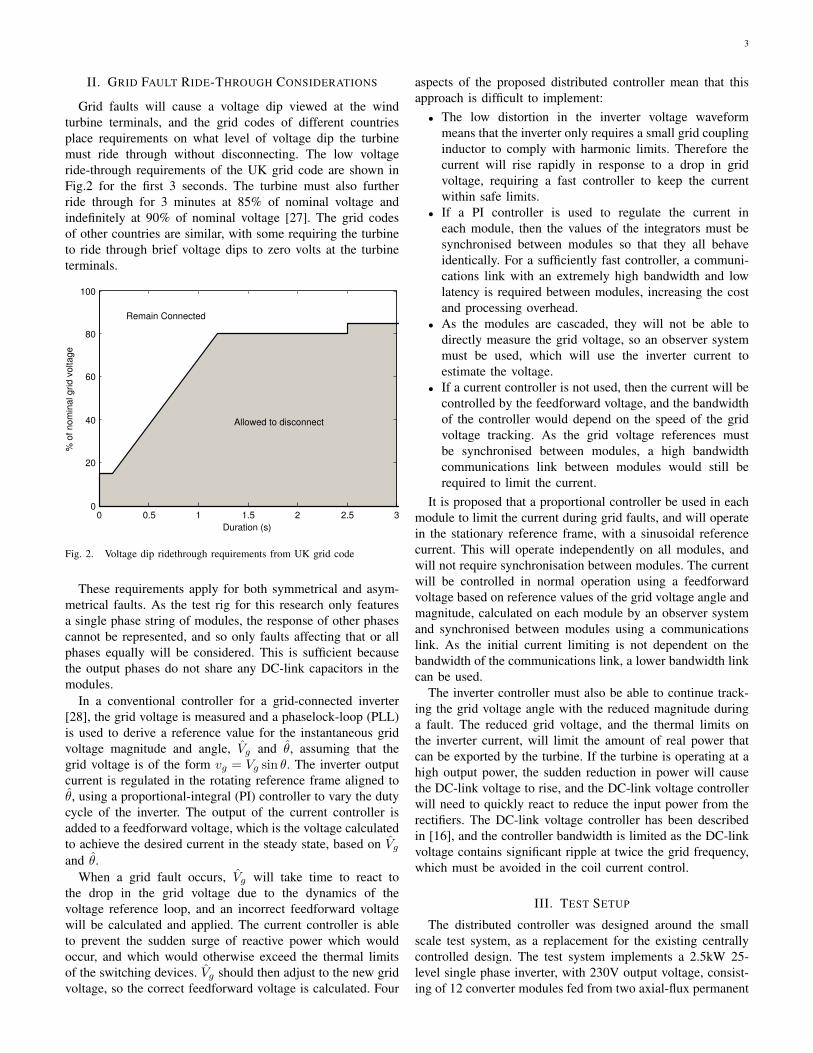
III. TEST SETUP
The distributed controller was designed around the small
scale test system, as a replacement for the existing centrally
controlled design. The test system implements a 2.5kW 25-
level single phase inverter, with 230V output voltage, consist-
ing of 12 converter modules fed from two axial-flux permanent
4
magnet generators each with 12 isolated coils. Each module
is connected to two coils, which have a 90◦ phase shift,
to provide constant power. The generators are driven by an
induction motor through a reduction gearbox, connected to a
variable speed drive. The test setup is shown in Fig.3.
(a)
Converter rack
InductionMotor
Axial-fluxgenerators
Motor drive
Grid isolationtransformerand variac
(b)
Control Board 2 Rectifiers
Power Board H-Bridge Inverter
(c)
Fig. 3. Experimental system, featuring (a) System diagram (b) Test systemarrangement, and (c) Individual converter module board
For the ease of access and programming, the converter
modules are designed to plug into a eurocard subrack, which
is mounted close to the generators. Each converter module
consists of a power board, incorporating the switching devices,
capacitors, gate drive and current and voltage transducers.
Attached to the power board is a control board, developed
around a TMS320F2808 microcontroller, which contains the
peripheral devices required by the application. The control
board also provides all the optically isolated communication
interfaces. The control board samples the inverter output
current, the DC-link voltage and the currents in the connected
coils.
Synchronisation of the module grid voltage references is
carried out over a CAN bus, which is a multi-master pro-
tocol, allowing any node to communicate with any other,
and is designed for fault tolerance. CAN was chosen as it is
implemented in hardware on many microcontrollers, without
requiring extra ICs to be added, which would increase the cost
and size of the control board. Other communication protocols
implemented on the microcontroller, such as SPI and I2C are
designed for short range communication between ICs, and are
unsuitable for this application, and using an RS485 serial link
would require the higher level protocols to be implemented in
software, adding a significant processing overhead.
CAN uses a small message frame size and bit rates of
up to 1Mbps, so message latency is low, which is ideal
for synchronisation purposes [29], it also has a high noise
immunity. As standard, CAN does not include any galvanic
isolation, which is required in this application, so this is added
using opto-couplers between the microcontroller and the CAN
transceiver. A full size converter will require higher isolation
voltages, possibly using optical fibres, so CAN may not be
appropriate, or may require significant adaptation.
CAN is tolerant of faults in individual nodes, as each node is
able to detect when it is not transmitting or receiving messages
properly and ceases operation after a set number of errors.
This will cause the module with the communication failure to
cease operation, which the inverter is able to tolerate [16]. The
fault response relies on the node controller being active, and
a fault in which causes a faulty node to lock up the bus or a
short circuit in the bus itself will prevent any communication
between modules, causing the inverter to shut down. Star-
based implementations have been designed which improve the
fault tolerance [30].
Each message frame has an identification field, and if two
messages are transmitted simultaneously the message with the
lower value in the identification field will override the one with
the higher value, which will be forced to stop transmitting until
the bus is free. Because of this, message latency is highly de-
terministic, unlike most other communications protocols, and
messages are assigned different priorities based on the value
of the identification field. The identification field represents
the contents of the message data rather than the intended
receiver. Each message is received by all nodes on the CAN
bus, and the individual CAN controllers can be programmed to
accept messages or to ignore them without alerting the CPU,
depending on the identifier.
A disadvantage of the CAN protocol is that each node
must receive each bit of the message within the narrow time
window before the next bit is sent, in order to be able to
determine which message has the higher priority. This limits
the maximum data rate and bus length, with 1Mbps only
achievable with bus lengths of 20m or shorter, although this
is adequate for the proposed application. Faster fault-tolerant
communication buses exist, such as FlexRay and Spacewire,
5
which are designed for automotive and aerospace applications
[31], but these are not implemented on any low cost micro-
controllers, and would require extra hardware, increasing the
control board size and cost.
The modules also feature an RS485 interface, implementing
the MODBUS protocol, for communication with a host PC for
data acquisition, and to vary the converter operating mode and
setpoints. The inverter is connected to the grid through a 9mH
coupling inductor.
IV. DISTRIBUTED CONTROLLER DESIGN
A PWM switching scheme is used for the inverter switching,
for ease of controllability during module and grid faults. Fun-
damental frequency switching gives lower switching losses,
but during grid faults or voltage dips, the minimum voltage
output of the inverter will be limited by the minimum DC-
link voltages of the modules, which due to the nature of the
boost rectifier is determined by the turbine speed. Following
a module fault, the output voltages of the remaining modules
must be raised, which requires the DC-link voltages to be
raised if fundamental frequency switching is used. This is
slower than simply changing the modulation depth in a system
with PWM switching, and could apply unwanted transient
loads to the generator and turbine rotor.
For ease of implementation in a distributed system, and to
equalise power sharing and switching losses between modules,
a phase-shifted PWM system is used. This also allows the
control system to be used with an inverter having a lower
number of modules. As the power sharing between modules
is unlikely to be exactly equal, the module DC-link voltages
will need to be individually controlled. In this system, the
DC-link voltage is held constant, by varying the rectifier
current demand, and the duty cycle of the module inverter
H-bridge is determined by a reference voltage waveform, the
magnitude and phase of which are selected to achieve the
desired current output, to achieve the required power output.
This is the opposite of the approach usually taken in grid-
connected inverters.
To keep costs down, the grid coupling inductance should be
as small as possible. The use of a multilevel converter provides
an output voltage with low distortion while still using a low
inverter switching frequency, which allows a much smaller
inductor to be used than for standard 2- and 3-level converters.
With the test system, an inductor providing a per-unit reactance
of 0.045 was initially specified, although this was increased to
0.14 p.u. due to distortion in the background grid voltage.
The distributed controller consists of four inter-linked ele-
ments:
• A method to interleave the phase-shifted PWM carriers of
the different modules. The PWM carrier on each module
also determines the instance the ADC samples the grid
current, which triggers the interrupt to run the control
algorithms. Therefore, properly interleaving the module
PWM carriers will ensure that the ADC sampling on all
modules occurs simultaneously.
• A method to set the output voltage of each module to
achieve the desired current, based on a reference value
of the grid voltage magnitude and phase, and also to
limit the current in the event of a grid fault. Current
limiting must operate independently on each module
due to the limited bandwidth of the CAN bus used for
communications between modules.
• A PLL system to maintain a reference of the grid voltage
angle and magnitude, based on the estimated grid voltage,
and a method to synchronise the grid voltage references
of all the modules.
• An observer system to estimate the grid voltage, based
on the previously applied inverter output voltage and re-
sulting current. This will run separately on all the module
controllers, and the code should execute simultaneously
if the modules are properly synchronised. In other words,
the estimated grid voltage should be equal on all modules.
A. PWM Interleaving and Sampling Synchronisation
The inverter PWM carrier on each module, synthesised dig-
itally in the microcontroller, operates at a frequency of 333Hz,
and bipolar switching is used to double the effective module
switching frequency while keeping the switching frequency of
each individual leg at 333Hz [32]. When interleaved properly,
the 12-module inverter has an apparent switching frequency
of 8kHz.
Sampling of the inverter output current by the modules, and
the operation of the control algorithm, is done at twice the
apparent frequency, i.e. 16kHz, in order to avoid aliasing, and
is synchronised to the PWM carriers on each module. If the
PWM carriers of each module are properly interleaved, then
the modules should all be sampling the current at the same
time.
Interleaving is carried out by having each module send out
a message frame on the CAN bus whenever its PWM carrier
reaches either the maximum or minimum value, while listening
out for messages from other modules. Using timestamps for
the received messages, provided by the CAN controller on the
microcontroller, the control algorithm can calculate the time
difference between its PWM carrier and those of the previous
and next modules in the sequence. The period of the module’s
PWM carrier can then be shortened or lengthened temporarily
to minimise this difference, equalising the time period between
messages, as shown in Fig.4.
If one module in the inverter fails, it will stop transmitting
its synchronisation message. The remaining modules will then
adjust their PWM carriers such that the gap in the switching
waveform is eliminated, and the module PWM carriers re-
main equally spaced. This method is similar to an analogue
synchronisation method for interleaved converters [33], and
offers greater flexibility due to the digital implementation, but
a lower maximum PWM switching speed due to the limited
bandwidth and message timestamp resolution of the CAN bus
and controller.
In practice, in order to conserve the bandwidth of the CAN
bus, messages are only sent out every seventh PWM carrier
maximum or minimum, resulting in 1143 messages sent per
second from all 12 modules. The prototype inverter has 12
modules, and is designed to function with 11 or 10 modules.
6
�� �� �������
�� �� �������
���
��� ���
���
�������
���
��� ���
���
�������
Fig. 4. Synchronisation and interleaving of PWM carrier waveforms
7 is not a factor of any of these numbers, so this method will
still result in proper interleaving of the module PWM carriers.
With a message frame of 44 bits in length (CAN message
frame with standard identifier and no data), this will require
a bandwidth of around 50kbps, a small fraction of the 1Mbps
available.
B. Current Control
A single phase string of n modules is shown in Fig.5. Each
module m produces an output voltage vm, and the total output
voltage v is the sum of the outputs of the individual modules,
given by (1). The grid is modelled as a voltage source, of
voltage vg , and a coupling inductor of inductance L and
resistance R is used. It is assumed that the grid inductance
will be significantly lower than that of the coupling inductor.
A current i will flow.
Module 1
Module 2
Module 3
Module n
v1
v2
v3
vn
v vg
R Li
GridCAN
bus
Fig. 5. Connection arrangement for a single phase string of modules.
v =
n∑
m=1
vm (1)
Control of the inverter current is primarily achieved using
a feedforward system, which calculates the inverter voltage
necessary to achieve the desired current based on reference
values of the grid voltage magnitude and angle from a PLL
[34]. The relationship between v, i and vg is given by (2).
The grid voltage is assumed to be sinusoidal, of the form
vg = Vg sin θ, where Vg is the magnitude of the grid voltage
and θ the angle. v and i are also assumed to be sinusoidal.
v = vg + iR+ Ldi
dt(2)
Calculation of the feedforward voltage takes place in the
rotating reference frame, with the q-axis aligned to the ref-
erence grid voltage angle θ̂ from the PLL. The value of
the feedforward voltage Vffd,q required to achieve an inverter
current I∗d,q is given by (3), where ω̂ is the reference grid
frequency and V̂g is the reference grid voltage magnitude.
[
Vffd
Vffq
]
=
[
0
V̂g
]
+
[
R 0
0 R
] [
I∗dI∗q
]
+
[
0 −ω̂L
ω̂L 0
] [
I∗dI∗q
] (3)
Two current control modes, using the feedforward voltage
calculated with (3), are implemented, and these are shown in
Fig.6. For normal operation, shown in Fig.6(a) the inverter
acts as a voltage source, producing a sinusoidal voltage, and
allowing the grid to draw any current harmonics corresponding
to the grid voltage.
On the occurance of a grid fault or during synchronisation,
the grid voltage could be significantly different from the
value previously estimated, leading to an incorrect feedforward
voltage being applied until the grid voltage estimator catches
up with the change in grid voltage. This will lead to a rapid
rise in the current due to the low grid coupling inductance. The
limited communication bandwidth between modules limits the
bandwidth of the voltage estimator, so the feedforward voltage
cannot be updated quickly enough to limit the current. For
these scenarios a current limiting mode was implemented,
shown in Fig.6(b), based on using a proportional controller
to limit the current in the stationary reference frame. This
mode will cause the inverter to produce a sinusoidal current
waveform whatever the shape of the grid voltage waveform.
In the basic control scheme using PWM switching in
each module, shown in Fig.6(a), the feedforward voltage is
converted to the fixed reference frame using the e−jθ block
and the estimated grid voltage angle θ̂. The voltage is then
used to set the PWM duty cycle based on (4), where Vdc is the
DC-link voltage in the module and n the number of modules.
As the inverter output voltage v is the sum of all the module
voltages, the time-averaged output voltage will equal vff.
d =1− vff
nVdc
(4)
In the current limiting mode of operation, shown in Fig.6(b),
the same feedforward calculation is used. Additionally, the
reference demand I∗d,q is converted to the fixed reference
frame current demand i, which is used in a proportional
controller to modify the duty cycle and force the current
to follow the demand. The use of a proportional controller,
7
Feedforward
calculation e− j Inverter
1−v
nVdc
iv ff d
Grid voltage
reference
V g
I d*
I q*
V ffd
V ffq
(a)
Feedforward
calculatione− j
Inverter1−v
nV dc
v ff d
e− j K
p
i*
d ff i
i
I d*
I d*
I q*
I q*
Grid voltage
reference
V g
V ffd
V ffq
(b)
Fig. 6. Inverter current control modes, featuring (a) Feedforward controlwith PWM switching, (b) Current limiting control with PWM switching.
and the fact that all modules should be sampling the current
simultaneously, means that the current limiting action will be
identical in all modules so long as their grid voltage references
are synchronised. This allows the current limiting controllers
in each module to function independently, with a much higher
bandwidth than that of the CAN bus connecting them.
The main disadvantage with using a proportional controller
is that there will be a steady state error between the grid current
and current demand, with the size of the error depending
on the proportional gain. This will only occur immediately
after a grid fault or grid synchronisation, when the estimated
grid voltage is significantly different from the actual voltage,
resulting in an incorrect feedforward voltage being used.
C. Grid Voltage Reference Loop
A reference value of the grid voltage angle θ̂, is maintained
on each module using a phaselock loop (PLL), and is used
for transformation to and from the rotating reference frame.
The PLL works by comparing θ̂ with the measured grid
voltage angle θ, and calculating the phase difference φ. φ
is then passed through a loop filter, the output of which is
the reference frequency ω̂, which is integrated to give θ̂. As
the grid frequency varies, the loop controls ω̂ to minimise
φ, meaning that θ̂ tracks θ. θ cannot be measured directly,
and must be estimated from other parameters, the method for
which is described in the next section.
A proportional-integral (PI) controller is used for the loop
filter in order to avoid a steady state error between the grid
angle reference and the actual grid angle, which would result
in the current being different from the demand. The use of a
PLL provides stable tracking of the grid voltage angle, without
a phase delay, and with good noise rejection, and the level of
noise rejection depends on the bandwidth of the loop filter. The
grid voltage magnitude reference, V̂g , is obtained by filtering
the estimated instantaneous value of the magnitude using an
integrator, which will be expanded on later in this section.
This system requires θ̂ to be synchronised between modules,
which is similar to the problem of synchronising clocks
between multiple nodes in a distributed system [35], especially
a system where a relative time is synchronised between
nodes rather than an absolute time obtained externally. Both
centralised and decentralised algorithms of varying complexity
exist.
A simple decentralised method of synchronising reference
angles, described in [35], is for each module to periodically
broadcast what reference angle it has, onto the network, with
the modules collecting the values from each other and updating
their own reference angle with the average. A better algorithm,
especially designed for use with the CAN system, is described
in [36], but for simplicity the simple averaging system will be
used.
Instead of having all the modules periodically broadcast
their reference values for grid voltage angle and magnitude,
the modules attach these values to the message frames used
for interleaving the PWM switching. When a module receives
the message from another module, the message timestamp is
recorded. When the modules interrupt service routine (ISR)
runs, the message timestamp and current value of the timer
can be used to compensate for the delay between reception of
the message and operation of the ISR.
The structure of the complete grid voltage angle reference
loop for one module is shown in Fig.7. The ‘Grid Phase
Detector’ block, to be described in the next section, estimates
the phase difference φ2 between the grid voltage angle and
the reference angle θ̂. The values of θ̂ from other modules,
represented as θ̂n, are received on the CAN bus individually,
one module at a time. The phase difference between the most
recently received θ̂n, and the local θ̂, is is labelled φ1.
KP1
KP2
KI1
KI2
∫
∫
Bias LimitFrequency Bias
50Hz
Grid Phase
Detector
CAN
bus
F Limit
Loop Filter
1
2
n
d
i
CAN
bus
From other
modulesTo other
modules
Current
Controller
Fig. 7. Distributed grid voltage angle reference
In the loop filter, φ1 and φ2 are combined, through separate
proportional and integral gains KP1,2 and KI1,2, and the
filtering effect of the PI controller is used to average the values
of φ1 from different modules. The separate gains allow the
influence of the two inputs on the reference frequency ω̂ to be
adjusted, and it was found that using the same proportional and
integral gains for both inputs gave an acceptable performance.
A system is also included to bias the frequency towards 50Hz
as, in the absence of a detectable grid voltage, such as when
disconnected, islanded or during a severe voltage dip, the
frequency will tend to drift.
The structure of the grid voltage magnitude reference for
one module is shown in Fig.8, and follows a similar, but
8
simpler structure to the angle reference loop. Again a system is
used to bias the voltage magnitude reference towards 230V, the
nominal grid voltage in the test system, to prevent it drifting
when the system is not connected. An integral controller is
required for this use, as it allows the voltage magnitude to be
biased towards a particular value, while limiting the influence
of the bias (through a saturation function) when the grid
voltage is substantially different from the bias value, i.e. during
a severe voltage dip.
KI1
KI2
∫
Bias Limit
Voltage Bias
230V
Grid VoltageDetector
CANbus
V g
V g
V g
V ge1
e2V g
e
Vgn CAN
bus
d
iCurrent
Controller
Fig. 8. Distributed grid voltage magnitude reference
D. Grid Voltage Estimator and Phase Detector
As the system is distributed between many identical mod-
ules, the grid voltage cannot be measured directly as this
would require a central voltage sensor, defeating the purpose of
having a distributed modular system. A method of estimating
the grid voltage from the current is required, and a suitable al-
gorithm is described in [34], which will operate independently
on all modules.
Based on (2), the instantaneous grid voltage can be esti-
mated if the inverter output voltage and current are known,
along with the resistance and inductance of the coupling
inductor. The instantaneous grid voltage is estimated in the
rotating reference frame aligned to the reference value of the
grid voltage angle, θ̂, as used for calculating the feedforward
voltage. The estimated grid voltage V egd,q is given by (5), where
Vd,q is the voltage applied by the inverter in the previous
controller cycle, and Id,q is the measured inverter current
transformed into the rotating reference frame.
[
V egd
V egq
]
=
[
Vd
Vq
]
−
[
R 0
0 R
] [
IdIq
]
−
[
0 −ω̂L
ω̂L 0
] [
IdIq
] (5)
If the inverter is not operating in the current limiting mode,
the inverter output voltage Vd,q is assumed to be the same as
the feedforward voltage calculated by the current controller
in the previous cycle. This assumes that all the modules
have calculated and applied the same feedforward voltage,
which would be the case if their grid voltage references and
current demands are identical. If the current limiting mode
is activated, the applied voltage must be calculated from
the previously applied duty cycle and the DC-link voltage,
according to (4), as the duty cycle will have been modified
by the current limiting controller. The voltage estimator, for
the current limiting mode, is shown in Fig.9, and combines
v fbkd
fbk
ej i
Vd
Vq
Id
Iq
g
ej 1−d nV
dc
100Hz
g
To mag-angle
Vgd
e
Vgq
eV
g
e
Grid Voltage
Estimation
Fig. 9. Grid voltage and phase detector
the Grid Phase Detector block in Fig.7 and the Grid Voltage
detector in Fig.8.
Using a single-phase reference transformation results in a
significant ripple in the transformed signals, at twice the grid
frequency, and this is removed using notch filters tuned to
100Hz. The dynamics of the notch filters must be considered
when designing the loop filter. As V egd,q are calculated in the
rotating reference frame aligned to θ̂, the angle between the
vector V egd,q and the q-axis is the angle φ2, used in the PLL,
while the magnitude of the vector is the estimated grid voltage
magnitude V eg , used in the grid voltage magnitude reference
loop.
E. Selection of Loop Filter Parameters
The PLL loop filter gains were selected to maximise the
response speed while keeping the bandwidth below the notch
filter frequency, to minimise the interaction with the notch
filter. The selected gains give a bandwidth of 30Hz and
a damping ratio of 0.707. The simulated response of the
reference angle θ̂ to a unit step change in grid frequency is
shown in Fig.10, in which the influence of the inter-module
synchronisation system is ignored.
0 0.02 0.04 0.06 0.08 0.1 0.12 0.14 0.160
0.2
0.4
0.6
0.8
1
1.2
1.4
Step Response
Time (sec)
Am
plit
ude
Fig. 10. Simulated step response of the grid angle reference loop
The integral gain of the voltage reference filter was selected
to provide a high bandwidth, while keeping the closed loop
poles a reasonable distance from those of the notch filter to
prevent unwanted interactions, and a bandwidth of 50Hz was
achieved. The response of the voltage reference filter to a unit
step change in input voltage is shown in Fig.11. The step
response of the voltage reference, without including the notch
9
filter, is also shown, and shows that the influence of the notch
filter is within acceptable bounds.
0 0.01 0.02 0.03 0.04 0.05 0.06 0.07 0.080
0.2
0.4
0.6
0.8
1
Step Response
Time (sec)
Am
plit
ude
Grid Vref filter
Combined Vrefand notch filter
Fig. 11. Simulated step response of the grid voltage reference filter
V. TEST RESULTS
All testing is based on using PWM switching in the inverter
modules, with the DC-link voltage demand on all modules held
constant at 32V.
A. PWM Interleaving
Activity on the CAN bus with the PWM carriers of all
12 modules synchronised is shown in Fig.12a. CAN uses
differential signalling, where the signal is the difference be-
tween the voltages on two wires, which are labelled CAN
High and CAN Low in the figure. The messages on the
CAN bus are evenly spaced, so the PWM carriers will be
interleaved. Fig.12b shows the synchronisation error recorded
by the module controllers. This is the error calculated by the
module between its PWM carrier peak, and where the peak
should be, based on the peaks of the next and previous modules
in the sequence. This error is then used by the module to
modify the timing of its own carrier.
The error signal shows a jitter of around 20µs, and as the
synchronisation pulses are sent out every seventh PWM carrier
peak, this represents a jitter in the PWM carrier of 2.9µs,
which is small compared to the 3ms time period of each PWM
carrier. The error appears to oscillate, and it is expected that
detailed modelling of the control action and CAN bus could
result in a significantly lower jitter.
B. Current Control
Testing of the inverter current limiting operation was carried
out by fixing the magnitude of the feedforward voltage, and
shorting the inverter terminals. The inverter current demand is
set to zero. The inverter current and voltage waveforms were
recorded on an oscilloscope, and are shown in Fig.13a. The
feedforward and applied voltages are recorded on the module
controllers, as shown in Fig.13b for one module.
The proportional current controller is able to reduce the ap-
plied voltage and counteract most of the feedforward voltage,
CAN High
CAN Low0.88ms
(a)
0 0.01 0.02 0.03 0.04 0.05 0.06−20
−15
−10
−5
0
5
10
15
20
25
time (s)
PW
M E
rro
r (µ
s)
Module 1
Module 3
Module 5
Module 7
(b)
Fig. 12. PWM synchronisation (a) Activity on CAN bus with 12 modules,(b) Synchronisation error recorded by the module controllers.
but the chosen proportional gain gives a significant steady-state
error, while also causing some high frequency instability in the
applied voltage signal. Decreasing the proportional gain will
reduce the applied voltage instability and increase the steady
state error, while increasing the proportional gain will have
the opposite effect.
Operation of the inverter in current limiting mode with a
grid connection was also tested, and the results are shown
in Fig.14 for stable operation and for operation with a high
proportional gain leading to instability in the inverter current.
It was found that the limit to the proportional gain for stable
operation varied with the current demand, with a higher current
demand requiring a lower gain to maintain stability. The
dynamic response of the current controller will be shown later.
C. Grid Voltage Estimation and Synchronisation
The grid voltage magnitude and frequency reference values
were captured from four modules while the inverter was
connected to the grid, in order to verify the quality of the grid
voltage tracking. The results are shown in Fig.15. The grid
voltage reference is the peak voltage seen by each module,
10
Inverter VoltageCurrent
(a)
0 0.02 0.04 0.06 0.08 0.1−30
−20
−10
0
10
20
30
time (s)
Voltage (
V)
Feedforward Voltage
Applied Voltage
(b)
Fig. 13. Behaviour of the current limiting controller with the inverterterminals shorted (a) Measured inverter current and voltage, (b) Feedforwardvoltage and applied voltage signals per module.
with an RMS grid voltage of 230V this is√2×230V12
= 27.1V.
Some high frequency noise is present in the frequency estima-
tion, and some interference at the grid frequency in the voltage
estimation but in general the noise levels are low.
The dynamic response of the grid voltage estimation con-
troller can be seen when the inverter is connected to the grid
while in an unsynchronised state. This was the method used to
synchronise the inverter to the grid voltage, as the inverter has
no way of measuring the grid voltage before it is connected.
The response is shown in Fig.16, in which the grid and inverter
voltage and current were recorded using an oscilloscope and
the remaining quantities recorded on the controllers of several
different modules. The current limiting mode was activated
before the inverter was connected.
The initial grid frequency was almost the same as that of
the module’s reference frequencies, but a significant phase
difference was used in order to achieve a worst case scenario.
The current controllers are able to limit the current, but a
significant transient current still flows, and causes the DC-
link voltage on the modules to increase. The time taken for
the phase of the grid reference PLL to match that of the grid
Inverter Voltage
Current
(a)
Inverter Voltage
Current
(b)
Fig. 14. Current limiting mode applied to grid connection (a) Stable operation(KP = 4), (b) Unstable operation with higher proportional gain (KP = 5).
voltage is limited by limits placed on the allowable frequency
values, and a faster acquisition speed could be achieved if
these are removed during synchronisation. The responses of
all modules are identical, verifying the effectiveness of the
synchronisation method using the CAN bus.
During the acquisition period, power flows from the grid
into the inverter, which results in the DC-link voltage of
the modules increasing significantly. Each module features a
braking circuit which is able to dissipate some power into a
resistor, but the capacity of this circuit is small, and not able
to fully limit the DC-link voltage. The response speed of the
DC-link voltage controller on the rectifier side is also limited
to avoid interacting with the 2nd harmonic ripple.
D. Grid Fault Ride-through and Module Fault Tolerance
Testing of the response to the loss of a module was carried
out in the normal feedforward current control mode, with
PWM switching. A more detailed discussion of the module
fault response can be found in [16], where fundamental
11
0 0.05 0.1 0.15 0.249.95
50
50.05
50.1G
rid F
requency
Refe
rence (
Hz)
0 0.05 0.1 0.15 0.227.09
27.1
27.11
27.12
27.13
time (s)
Grid V
oltage
Refe
rence (
V)
Fig. 15. Grid frequency and voltage references from four modules.
0.3 0.35 0.4 0.45 0.5 0.55 0.6−500
0
500
Outp
ut
Voltage (
V)
0.3 0.35 0.4 0.45 0.5 0.55 0.6−10
0
10
Outp
ut
Curr
ent (A
)
0.3 0.35 0.4 0.45 0.5 0.55 0.645
50
55
Estim
ate
d G
rid
Fre
quency (
Hz)
0.3 0.35 0.4 0.45 0.5 0.55 0.6150
200
250
Estim
ate
d G
rid
Voltage (
V r
ms)
0.3 0.35 0.4 0.45 0.5 0.55 0.630
40
50
time (s)
DC
−Lin
kV
oltage (
V)
Module 1
Module 3
Module 5
Module 7
Module 1
Module 3
Module 5
Module 7
Module 2
Module 6
Module 8
Grid Voltage
Inverter Voltage
Fig. 16. Acquisition of the grid voltage and frequency when first connected.
frequency switching is used. The fault is emulated by having
one module hold its output voltage at zero on a command
from the host PC, while also ceasing to send synchronisation
messages on the CAN bus, which represents a complete failure
of the module control system and activation of the bypass
switch.
The response to a module loss is shown in Fig.17. The
inverter output voltage and current were recorded on an oscil-
loscope, while the estimated grid voltage was obtained from
one of the module controllers and scaled to the RMS value of
the inverter with 12 modules. The remaining modules interpret
the loss of one module as a step change in the grid voltage
magnitude, and are able to adjust quickly, without entering
the current limiting mode of operation. The interleaving of the
PWM waveform is adjusted over a period of around 0.25s.
0 0.05 0.1 0.15 0.2 0.25 0.3 0.35−500
0
500
Inve
rte
rV
olta
ge
(V
)
0 0.05 0.1 0.15 0.2 0.25 0.3 0.35−10
0
10
Ou
tpu
tC
urr
en
t (A
)
0 0.05 0.1 0.15 0.2 0.25 0.3 0.35230
240
250
260
time (s)E
stim
ate
d G
rid
Vo
lta
ge
(V
)
Fig. 17. Response of the system to the loss of a single module.
A system for emulating grid faults was not available, so
an approximation of the grid fault performance was obtained
by connecting the inverter to a resistive load bank. The grid
frequency estimator was disabled, the current demand set to
around 4A and the resistance adjusted until that current was
achieved with a 230V output voltage. The feedforward current
control mode was used, with PWM switching in each module.
To emulate a grid fault, the resistance was quickly reduced to
a low value by connecting an additional resistor in parallel
with the load bank.
The response to the emulated grid fault is shown in Fig.18,
where the inverter voltage and current were recorded using
an oscilloscope and the other quantities recorded on the
controllers of several modules. The drop in resistance causes
a spike in the inverter current, triggering the current limiting
mode of operation. The module controllers interpret the drop
in resistance as a drop in grid voltage, and the estimated grid
voltage is adjusted within two cycles of the inverter frequency.
The quick response of the grid voltage estimator, and the
associated change in feedforward voltage, means that the
steady state error from the current controller does not result
in a significant over-current. The response of the grid voltage
estimator is identical to that obtained in the module fault test,
which uses a grid connection, and the current limiter has been
shown to be capable of limiting the current during a short
circuit at the turbine terminals, suggesting that the converter
would be able to ride through a phase to ground fault.
A significant DC-link over-voltage occurs, which is due to
the limitations in the response speed of the DC-link voltage
controller implemented with the rectifier controller. The DC-
link voltage controller does not feature any feedforward signals
from the grid voltage estimator, and the addition of such
signals may help with limiting the overvoltage.
12
0.05 0.1 0.15 0.2 0.25 0.3 0.35 0.4−500
0
500In
ve
rte
r O
utp
ut
Vo
lta
ge
(V
)
0.05 0.1 0.15 0.2 0.25 0.3 0.35 0.4−20
0
20
Inve
rte
rC
urr
en
t (A
)
0.05 0.1 0.15 0.2 0.25 0.3 0.35 0.40
100
200
300
Estim
ate
d G
rid
Vo
lta
ge
(V
rm
s)
0.05 0.1 0.15 0.2 0.25 0.3 0.35 0.430
35
40
time (s)
DC
−L
ink
Vo
lta
ge
(V
)
Module 3
Module 5
Module 6
Module 7
Module 3
Module 5
Module 6
Module 7
Fig. 18. Response of the system to a drop in grid voltage.
Distortion in the current waveform can be seen in Fig.17,
even when the remaining modules have finished adjusting to
the module loss, and this is due to distortion in the grid voltage.
The current distortion is not present in Fig.14 or Fig.16 as
the current limiting mode forces the current to be sinusoidal.
Testing using a loadbank instead of a grid connection, as in
Fig.18, also shows a sinusoidal current, indicating that the
current distortion is due to the grid voltage.
VI. CONCLUSIONS
A fault tolerant distributed control system has been proposed
for a wind turbine grid interface based on a modular cascaded
multilevel inverter, which allows both the synchronisation of
the module switching waveforms and tracking of the grid
voltage without the use of a central controller. Each individual
module estimates the grid voltage magnitude and frequency,
and the modules are synchronised over a CAN bus, which is
also used to synchronise the module’s PWM carriers. A current
limiting system is implemented, which operates independently
on all modules.
Operation of the system has been verified in normal condi-
tions with a grid connection and emulated grid fault conditions
using a load bank. The emulated grid fault triggers the current
limiting mode which prevents over current, and the distributed
controller quickly recognises the change in load and adjusts
the output voltage demand. It is expected that the response
will be similar in a real grid fault condition.
The inverter is able to synchronise with the grid frequency
without damaging inrush currents, which is required after a
grid fault is cleared or when first connecting to the grid.
However, the synchronisation speed is limited by limits placed
on the frequency range the controller can operate in, which
could lead to significant DC-link over-voltage while synchro-
nising. Removing this limit could boost the synchronisation
speed. A faster grid frequency estimator could also be used
while synchronising, with the controllers switching to a slower
estimator when synchronised for better noise immunity.
Testing with a load bank suggests that the controller is able
to rapidly react to a drop in the grid voltage caused by a grid
fault, although this still results in a large DC-link over-voltage.
The DC-link voltage controller cannot react to the voltage
ripple at twice the grid frequency due to the single phase
inverter, and this limits the response speed of the controller. A
faster controller which does react to higher frequencies could
be used during a grid fault, or a feedforward term based on
the estimated grid voltage could be added to the controller.
These results were obtained using a test rig based on a single
phase inverter of 12 modules, and would also be valid for a
three phase inverter with the neutral point connected to ground,
and subjected to a phase to ground fault. Additional flexibility
and fault tolerance is possible in full three phase systems with
a floating neutral point, but in this case the dominant fault type
would be the phase to phase fault. This would be more difficult
to handle, requiring a modified control strategy. A fault tolerant
centralised carrier-based PWM scheme, for a converter with
floating neutral point, is described in [37],
The proposed control system is most relevant to the off-
shore wind turbine application, where multi-pole generators,
necessary to supply the isolated voltages, are often used,
and accessibility is difficult leading to a desire for fault
tolerance. The use of boost rectifiers to feed the DC-links
means that the modules each include a microcontroller-based
control system, so the additional control circuits are minimal.
The control method could also be applied to other modular
implementations of multilevel inverters, for example STAT-
COMs and HVDC converter stations, but these do not usually
have powerful controllers on the individual modules, and these
would need to be added, increasing cost.
REFERENCES
[1] G. J. W. van Bussel and M. B. Zaaijer, “Reliability, availability andmaintenance aspects of large-scale offshore wind farms, a conceptsstudy,” in IMarEst, MAREC Conference, Newcastle, UK, Mar. 2001.
[2] F. Spinato, P. J. Tavner, G. J. W. van Bussel, and E. Koutoulakos,“Reliability of wind turbine subassemblies,” IET Renew. Power Gener.,vol. 3, no. 4, pp. 387–401, 2009.
[3] D. McMillan and G. W. Ault, “Techno-economic comparison of opera-tional aspects for direct drive and gearbox-driven wind turbines,” IEEE
Trans. Energy Convers., vol. 25, no. 1, pp. 191–198, Mar. 2010.
[4] M. Liserre, R. Cardenas, M. Molinas, and J. Rodriguez, “Overview ofmulti-MW wind turbines and wind parks,” IEEE Trans. Ind. Electron.,vol. 58, no. 4, pp. 1081–1095, Apr. 2011.
[5] J. Li, S. Bhattacharya, and A. Q. Huang, “A new nine-level activeNPC (ANPC) converter for grid connection of large wind turbines fordistributed generation,” IEEE Trans. Power Electron., vol. 26, no. 3, pp.961–972, Mar. 2011.
[6] C. L. Xia, X. Gu, T. N. Shi, and Y. Yan, “Neutral-point potentialbalancing of three-level inverters in direct-driven wind energy conversionsystem,” IEEE Trans. Energy Convers., vol. 26, no. 1, pp. 18–29, Mar.2011.
[7] M. Abbes, J. Belhadj, and A. Bennani, “Design and control of a direct-drive wind turbine equipped with multilevel converters,” Renewable
Energy, vol. 35, no. 5, pp. 936–945, May 2010.
13
[8] R. Melicio, V. M. F. Mendes, and J. P. S. Catalao, “Harmonic assessmentof variable-speed wind turbines considering converter control malfunc-tion,” IET Renewable Power Generation, vol. 4, no. 2, pp. 139–152,Mar. 2010.
[9] M. Malinowski, S. Stynski, W. Kolomyjski, and M. P. Kazmierkowski,“Control of three-level PWM converter applied to variable-speed-typeturbines,” IEEE Trans. Ind. Electron., vol. 56, no. 1, pp. 69–77, Jan.2009.
[10] C. H. Ng, M. A. Parker, L. Ran, P. J. Tavner, J. R. Bumby, andE. Spooner, “A multilevel modular converter for a large, light weightwind turbine generator,” IEEE Trans. Power Electron., vol. 23, no. 3,pp. 1062–1074, May 2008.
[11] S. S. Gjerde and T. M. Undeland, “The best suitable multilevel convert-ers for offshore wind power generators without transformers,” in The
2010 International Power Electronics Conference, 2010.
[12] J. S. Lai and F. Z. Peng, “Multilevel converters – a new breed of powerconverters,” IEEE Trans. Appl. Ind., vol. 32, no. 3, pp. 509–517, 1996.
[13] P. W. Hammond, “A new approach to enhance the power quality formedium voltage drives,” IEEE Trans. Appl. Ind., vol. 33, no. 1, pp.201–208, 1997.
[14] P. Lezana, J. Pou, T. A. Meynard, J. P. Rodriguez, S. Ceballos, andF. Richardeau, “Survey on fault operation on multilevel inverters,” IEEE
[15] W. Song and A. Q. Huang, “Fault-tolerant design and control strategy forcascaded h-bridge multilevel converter-based STATCOM,” IEEE Trans.
Ind. Electron., vol. 57, no. 8, pp. 2700–2708, Aug. 2010.
[16] M. A. Parker, C. H. Ng, and L. Ran, “Fault tolerant control for a modulargenerator-converter scheme for direct-drive wind turbines,” IEEE Trans.
Ind. Electron., vol. 58, no. 1, pp. 305–315, 2011.
[17] E. Spooner, P. Gordon, J. R. Bumby, and C. D. French, “Lightweightironless-stator PM generators for drect-drive wind turbines,” IEE Proc.
Electr. Power Appl., vol. 152, no. 1, pp. 17–26, 2005.
[18] Z. Chen and E. Spooner, “A modular, permanent-magnet generator forvariable speed windturbines,” in Seventh international conference on
electrical machines and drives, Durham, UK, 1995, pp. 453–457.
[19] B. C. Mecrow, A. G. Jack, D. J. Atkinson, S. R. Green, G. J. Atkinson,A. King, and B. Green, “Design and testing of a four-phase fault-tolerant permanent-magnet machine for an engine fuel pump,” IEEE
Trans. Energy Convers., vol. 19, no. 4, pp. 672–678, 2004.
[20] H. Polinder, F. F. A. van der Pijl, G.-J. de Vilder, and P. J. Tavner,“Comparison of direct-drive and geared generator concepts for windturbines,” IEEE Trans. Energy Convers., vol. 21, no. 3, pp. 725–733,2006.
[21] P. C. Loh, D. G. Holmes, and T. A. Lipo, “Implementation and control ofdistributed PWM cascaded multilevel inverters with minimal harmonicdistortion and common-mode voltage,” IEEE Trans. Power Electron.,vol. 20, no. 1, pp. 90–99, Jan. 2005.
[22] C.-L. Chen, Y. Wang, J.-S. Lai, Y.-S. Lee, and M. D, “Design of parallelinverters for smooth mode transfer microgrid applications,” IEEE Trans.
Power Electron., vol. 25, no. 1, pp. 6–15, Jan. 2010.
[23] W. Yao, M. Chen, J. Matas, J. M. Guerrero, and Z.-M. Qian, “Design andanalysis of the droop control method for parallel inverters consideringthe impact of the complex impedance onthe power sharing,” IEEE Trans.
Ind. Electron., vol. 58, no. 2, pp. 576–588, Feb. 2011.
[24] K. I. Hwu and Y. H. Chen, “Current sharing control strategy based onphase link,” IEEE Trans. Ind. Electron., vol. 59, no. 2, pp. 701–713,Feb. 2012.
[25] Y. Zhang and H. Ma, “Theoretical and experimental investigation ofnetworked control for parallel operation of inverters,” IEEE Trans. Ind.
Electron., vol. 59, no. 4, pp. 1961–1970, Apr. 2012.
[26] P. Lezana and G. Ortiz, “Extended operation of cascaded multicellconverters under fault conditions,” IEEE Trans. Ind. Electron., vol. 56,no. 7, pp. 2697–2703, 2009.
[27] J. Schlabbach, “Low voltage fault ride through criteria for grid con-nection of wind turbine generators,” in 5th International Conference on
European Electricity Market. EEM 2008, May 2008.
[28] S. Alepuz, S. Busquets-Monge, J. Bordonau, J. Martinez-Velasco,C. Silva, J. Pontt, and J. Rodriquez, “Control strategies based onsymmetrical components for grid-connected converters under voltagedips,” IEEE Trans. Ind. Electron., vol. 56, no. 6, Jun. 2009.
[29] CAN Specification, Version 2.0, Robert Bosch GmbH Std., 1991.
[30] M. Barranco, J. Proenza, and L. Almeida, “Quantitative comparisionof the error-containment capabilities of a bus and star topology in CANnetworks,” IEEE Trans. Ind. Electron., vol. 58, no. 3, pp. 802–813, Mar.2011.
[31] F. Baronti, E. Petri, S. Saponara, L. Fenucci, R. Roncella, R. Saletti,P. D’Abramo, and R. Serventi, “Design and verification of hardwarebuilding blocks for high-speed and fault-tolerant in-vehicle networks,”IEEE Trans. Ind. Electron., vol. 58, no. 3, pp. 792–801, Mar. 2011.
[32] N. Mohan, T. M. Undeland, and W. P. Robbins, Power Electronics:
Converters, Applications and Design. John Wiley & Sons, 2003, ch. 8,pp. 211–221.
[33] D. J. Perreault and J. G. Kassakian, “Distributed interleaving of paral-leled power converters,” IEEE Trans. Circuits Syst. I, vol. 44, no. 8, pp.728–734, Aug. 1997.
[34] I. Agirman and V. Blasko, “A novel control method of a VSC withoutAC line voltage sensors,” IEEE Trans. Ind. Appl., vol. 39, no. 2, pp.519–524, Mar. 2003.
[35] A. S. Tannenbaum and M. van Steen, Distributed Systems: Principles
and Paradigms. Prentice Hall, 2002, ch. 5, pp. 241–258.[36] L. Rodruigues, M. Guimaraes, and J. Rufino, “Fault-tolerant clock
synchronization in CAN,” in RTSS’98, Madrid, Spain, Dec. 1998.[37] F. Carnielutti, H. Pinheiro, and C. Rech, “Generalized carrier-based
modulation strategy for cascaded multilevel converters operating underfault conditions,” IEEE Trans. Ind. Electron., vol. 59, no. 2, pp. 679–689,Feb. 2012.
Max Parker received his Engineering Doctorate(Eng.D.) degree in Power Electronics, Drives andMachines from the University of Newcastle UponTyne, UK, in 2009, with research carried out inthe School of Engineering, Durham University andsponsored by the New and Renewable Energy Centre(NaREC) in Blyth, UK. He is currently working asa research fellow with the Institute for Energy inthe Environment at the University of Strathclyde,Glasgow, UK, investigating collection network ar-chitectures for large offshore wind farms. His re-
search interests include digital control of power electronic systems, includingdistributed control systems, and control of large wind turbines and theassociated power systems.
Li Ran received the Ph.D. degree in PowerSystems Engineering from Chongqing University,Chongqing, China, in 1989. He participated in thecommissioning of Gezhouba-Shanghai HVDC Sys-tem in 1989. Between 1992 and 1999, he was aResearch Associate with the University of Aberdeen,Aberdeen, UK; the University of Nottingham, Not-tingham, UK and Heriot-Watt University, Edinburgh,UK. He was a Senior Lecturer in Power Electronicswith Northumbria University, Newcastle Upon Tyne,UK between 1999 and 2003, and was seconded to
Alstom Power Conversion at Kidsgrove, UK in 2001. Currently, he is aProfessor in Electrical Power and Control in the School of Engineering andComputing Sciences, Durham University, Durham, UK. His research interestsinclude the application of power electronics in power systems and renewableenergy systems, such as wave and wind energy converters.
Steven Finney obtained an MEng degree in Electri-cal and Electronic Engineering from LoughboroughUniversity of Technology in 1988. He worked for theElectricity Council Research Centre before joiningthe power electronics research group at Heriot-WattUniversity in 1990, receiving the award of PhD in1994. From 1994 to 2005 he was a member ofacademic staff at Heriot-Watt University. In 2005 hemoved to the University of Strathclyde where he isand currently Professor with the Institute of Energyand Environment , specialising in power electronic
systems. His research interests include the power electronics for high powerapplications and the management of distributed energy resources.