287
Parker O-Ring Handbook Catalog ORD 5700A/US Seals ISO 9001 / QS9000 Certified

Parker O-RingHandbook
Catalog ORD 5700A/US
Seals
ISO 9001 / QS9000 Certified

SectionsI Introduction to O-Ring SealingII Basic O-Ring ElastomersIII O-Ring ApplicationsIV Static O-Ring SealingV Dynamic O-Ring SealingVI ParBak™ Back-Up RingsVII Compatibility Tables for Gases,
Fluids, SolidsVIII SpecificationsIX SizesX AppendixXI Index
Parker Offer of Sale
ParkerO-RingHandbook2001 Edition
Copyright © 1999, 2001, Parker Hannifin Corporation, Cleveland, OH. All rights reserved.
Failure, improper selection or improper use of the products and/or systems describedherein or related items can cause death, personal injury or property damage.
This document and other information from Parker Hannifin Corporation, its subsidiaries and authorized distributors provides product and/or system options for furtherinvestigation by users having technical expertise. It is important that you analyze all aspects of your application and review the information concerning the product orsystem in the current product catalog. Due to the variety of operating conditions and applications for these products or systems, the user, through his or her own analysisand testing, is solely responsible for making the final selection of the products and systems and assuring that all performance, safety and warning requirements of theapplication are met.
The products describes herein, including without limitation, product features, specifications, designs, availability and pricing, are subject to change by Parker HannifinCorporation and its subsidiaries at any time without notice.
OFFER OF SALEThe items described in this document are hereby offered for sale by Parker Hannifin Corporation, its subsidiaries and its authorized distributors. This offer and itsacceptance are governed by the provisions stated on the separate page of this document entitled “Offer of Sale.”
WARNING
Seals
Parker Accessories for O-ring Users

Parker O-Ring Handbook5700 Handbook
i
Build With The Best!SealsParker Hannifin Corporation • O-Ring Division
2360 Palumbo Drive, Lexington, KY 40509Phone: (859) 269-2351 • Fax: (859) 335-5128
www.parker.com/o-ring
I. Introduction
II. Basic O-Ring Elastomers
III. O-Ring Applications
IV. Static O-Ring Sealing
V. Dynamic O-Ring Sealing
VI. Back-Up Rings
VII. Compatibility Tables for Gases, Fluids, Solids
VIII. Specifications
IX. Sizes
X. Appendix
XI. Index
TTTTTable ofable ofable ofable ofable ofContentsContentsContentsContentsContents

Parker O-Ring Handbook5700 Handbook Introduction
1-1
Build With The Best!SealsParker Hannifin Corporation • O-Ring Division
2360 Palumbo Drive, Lexington, KY 40509Phone: (859) 269-2351 • Fax: (859) 335-5128
www.parker.com/o-ring
Section IIntroduction
1.0 How to Use This Handbook .................................................................................................................... 1-2
1.1 What is an O-ring?............................................................................................................................ 1-2
1.2 What is an O-ring Seal? .................................................................................................................... 1-2
1.3 Advantages of O-rings ...................................................................................................................... 1-2
1.4 Operation ......................................................................................................................................... 1-3
1.5 O-ring Characteristics....................................................................................................................... 1-3
1.6 Limitations of O-ring Use ................................................................................................................ 1-4
1.7 Scope of O-ring Use ......................................................................................................................... 1-4
1.7.1 Static Seals ................................................................................................................................ 1-5
1.7.2 Reciprocating Seals .................................................................................................................. 1-5
1.7.3 Oscillating Seals ....................................................................................................................... 1-5
1.7.4 Rotary Seals .............................................................................................................................. 1-5
1.7.5 Seat Seals .................................................................................................................................. 1-6
1.7.6 Pneumatic Seals ........................................................................................................................ 1-6
1.7.7 Vacuum Seals ............................................................................................................................ 1-6
1.7.8 Cushion Installation .................................................................................................................. 1-6
1.7.9 Crush Installation...................................................................................................................... 1-6
1.7.10 Rod Wiper Installation ............................................................................................................ 1-6
1.8 O-rings as Drive Belts ...................................................................................................................... 1-7
1.9 Custom Molded Shapes .................................................................................................................... 1-7
1.10 Parker Engineering ......................................................................................................................... 1-7
1.11 Comparison of Common Seal Types .............................................................................................. 1-7
1.12 Recommended Design Procedure .................................................................................................. 1-7
1.12.1 O-Ring Design Procedure UsinginPHorm™ O-Ring Design & Material Selection Software ................................................. 1-8
1.12.2 Recommended Manual Design Procedure ............................................................................. 1-8
inPHorm™ is a trademark of Parker Hannifin Corporation.

Parker O-Ring Handbook5700 Handbook Introduction
1-2
Build With The Best!SealsParker Hannifin Corporation • O-Ring Division
2360 Palumbo Drive, Lexington, KY 40509Phone: (859) 269-2351 • Fax: (859) 335-5128
www.parker.com/o-ring
1.0 How to Use This Handbook
For those who are unfamiliar with O-ring design, it isrecommended that they first study this introductory sec-tion, becoming familiar with the basic principles of O-ringseals, their common uses and general limitations.
A basic glossary of O-ring and other sealing terms isavailable in the Appendix, Section X, which may beconsulted if unfamiliar words or technical terms areencountered. The seal design portions of this handbookexplain in detail the design process required depending onthe application.
Those who are already familiar with O-ring seal design maysimply refer to the appropriate design tables for the infor-mation needed. Even those who have designed many O-ring seals, however, may profit by reviewing the basicsfrom time to time.
1.1 What is an O-ring?
An O-ring is a torus, or doughnut-shaped ring, generallymolded from an elastomer, although O-rings are also madefrom PTFE and other thermoplastic materials, as well asmetals, both hollow and solid. This handbook, however,deals entirely with elastomeric O-rings.
O-rings are used primarily for sealing. The various types ofO-ring seals are described in this section under “Scope ofO-Ring Use.” O-rings are also used as light-duty, mechani-cal drive belts. More information, including design criteriaon O-ring drive belts and their application will be found inO-Ring Applications, Section III.
1.2 What is an O-ring Seal?
An O-ring seal is used to prevent the loss of a fluid or gas.The seal assembly consists of an elastomer O-ring and agland. An O-ring is a circular cross-section ring moldedfrom rubber (Figure 1-1). The gland — usually cut intometal or another rigid material — contains and supports the
O-ring (Figures 1-2 and 1-3). The combination of these twoelements; O-ring and gland — constitute the classic O-ringseal assembly.
1.3 Advantages of O-rings• They seal over a wide range of pressure, temperature
and tolerance.• Ease of service, no smearing or retightening.• No critical torque on tightening, therefore unlikely to
cause structural damage.• O-rings normally require very little room and are light
in weight.• In many cases an O-ring can be reused, an advantage
over non-elastic flat seals and crush-type gaskets.• The duration of life in the correct application corre-
sponds to the normal aging period of the O-ring material.• O-ring failure is normally gradual and easily identified.• Where differing amounts of compression effect the
seal function (as with flat gaskets), an O-ring is noteffected because metal to metal contact is generallyallowed for.
• They are cost-effective.
Figure 1-1: Basic O-ring
Groove
Bore
Piston Rod
Figure 1-2: Basic Gland
IntrIntrIntrIntrIntroductionoductionoductionoductionoduction
Figure 1-3: Gland and O-ring Seal

Parker O-Ring Handbook5700 Handbook Introduction
1-3
Build With The Best!SealsParker Hannifin Corporation • O-Ring Division
2360 Palumbo Drive, Lexington, KY 40509Phone: (859) 269-2351 • Fax: (859) 335-5128
www.parker.com/o-ring
1.4 Operation
All robust seals are characterized by the absence of anypathway by which fluid or gas might escape. Detail differ-ences exist in the manner by which zero clearance isobtained — welding, brazing, soldering, ground fits orlapped finishes — or the yielding of a softer materialwholly or partially confined between two harder and stiffermembers of the assembly. The O-ring seal falls in the latterclass.
The rubber seal should be considered as essentially anincompressible, viscous fluid having a very high surfacetension. Whether by mechanical pressure from the sur-rounding structure or by pressure transmitted through hy-draulic fluid, this extremely viscous fluid is forced to flowwithin the gland to produce “zero clearance” or block to theflow of the less viscous fluid being sealed. The rubberabsorbs the stack-up of tolerances of the unit and its internalmemory maintains the sealed condition. Figure1-4 illus-trates the O-ring as installed, before the application ofpressure. Note that the O-ring is mechanically squeezed outof round between the outer and inner members to close thefluid passage. The seal material under mechanical pressureextrudes into the microfine grooves of the gland. Figure 1-5 illustrates the application of fluid pressure on the O-ring.Note that the O-ring has been forced to flow up to, but notinto, the narrow gap between the mating surfaces and in sodoing, has gained greater area and force of sealing contact.Figure 1-6 shows the O-ring and its pressure limit with asmall portion of the seal material entering the narrow gap
between inner and outer members of the gland. Figure 1-7illustrates the result of further increasing pressure and theresulting extrusion failure. The surface tension of theelastomer is no longer sufficient to resist flow and thematerial extrudes (flows) into the open passage or clear-ance gap.
1.5 O-ring Characteristics
A very early and historically prominent user of O-rings(1)
cites a number of characteristics of O-ring seals which arestill of interest to seal designers. Extracts of the moregeneral characteristics are listed as follows:
Note: While Parker Seal generally agrees with theauthor on most of his statements, exception will betaken to certain generalizations due to more recentdevelopments in sealing geometry and improved elas-tomer technology.
A. The seals can be made perfectly leak-proof for cases ofstatic pistons and cylinders for fluid pressures up to 5000 psi.(Limit of test pressure). The pressure may be constant orvariable.
B. The seals can be made to seal satisfactorily betweenreciprocating pistons and cylinders at any fluid pressure upto 5000 psi. There may be slight running leakage (a fewdrops per hundred strokes) depending on the film-formingability of the hydraulic medium. O-rings can be usedbetween rotating members with similar results but in allcases the surface rubbing speed must be kept low.
C. A single O-ring will seal with pressure applied alternatelyon one side and then on the other, but in cases of severe loadingor usage under necessarily unfavorable conditions, seal lifecan be extended by designing the mechanism so that each sealis subjected to pressure in one direction only. Seals may bearranged in series as a safety measure but the first seal exposedto pressure will take the full load.
D. O-ring seals must be radially compressed between thebottom of the seal groove and the cylinder wall for propersealing action. This compression may cause the seal to rollslightly in its groove under certain conditions of piston motion,but the rolling action is not necessary for normal operation ofthe seals.
E. In either static or dynamic O-ring seals under highpressure the primary cause of seal failure is extrusion of theseal material into the piston-cylinder clearance. The majorfactors affecting extrusion are fluid pressure, seal hardnessand strength, and piston-cylinder clearance.
F. Dynamic seals may fail by abrasion against the cylinderor piston walls. Therefore, the contacting surfaces shouldbe polished for long seal life. Moving seals that pass over
(1) “O-Ring Seals in the Design of Hydraulic Mechanisms”, a paper presented at the S.A.E. Annual Meeting, January, 1947 by Mr. D. R. Pearl of Hamilton Standard Prop.Div. of United Aircraft Corp.
Figure 1-6: O-ringExtruding
Figure 1-5: O-ring UnderPressure
Figure 1-7: O-ring Failure
Figure 1-4: O-ring Installed

Parker O-Ring Handbook5700 Handbook Introduction
1-4
Build With The Best!SealsParker Hannifin Corporation • O-Ring Division
2360 Palumbo Drive, Lexington, KY 40509Phone: (859) 269-2351 • Fax: (859) 335-5128
www.parker.com/o-ring
ports or surface irregularities while under hydraulic pres-sure are very quickly cut or worn to failure.
G. The shape of the seal groove is unimportant as long as itresults in proper compression of the seal between thebottom of the groove and the cylinder wall, and providesroom for the compressed material to flow so that the seal isnot solidly confined between metal surfaces.
H. The seal may be housed in a groove cut in the cylinderwall instead of on the piston surface without any change indesign limitations or seal performance.
I. Friction of moving O-ring seals depends primarily onseal compression, fluid pressure, and projected seal areaexposed to pressure. The effects of materials, surfaces,fluids, and speeds of motion are normally of secondaryimportance, although these variables have not been com-pletely investigated. Friction of O-ring seals under lowpressures may exceed the friction of properly designed liptype seals, but at higher pressures, developed frictioncompares favorably with, and is often less than, the frictionof equivalent lip type seals.
J. The effects of temperature changes from +18°C to +121°C(-65°F to +250°F) on the performance of O-ring seals dependsupon the seal material used. Synthetic rubber can be made forcontinual use at high or low temperatures, or for occasionalshort exposure to wide variations in temperature. At extremelylow temperature the seals may become brittle but will resumetheir normal flexibility without harm when warmed. Pro-longed exposure to excessive heat causes permanent harden-ing and usually destroys the usefulness of the seal. Thecoefficient of thermal expansion of synthetic rubber is usuallylow enough so that temperature changes present no designdifficulties. (Note: This may not be true for all elastomercompounds, especially FFKM.)
K. Chemical interaction between the seal and the hydraulicmedium may influence seal life favorably or unfavorably,depending upon the combination of seal material and fluid.Excessive hardening, softening, swelling, and shrinkagemust be avoided.
L. O-ring seals are extremely dependable because of theirsimplicity and ruggedness. Static seals will seal at highpressure in spite of slightly irregular sealing surfaces andslight cuts or chips in the seals. Even when broken or wornexcessively, seals may offer some measure of flow restric-tion for emergency operation and approaching failure be-comes evident through gradual leakage.
M.The cost of O-ring seals and the machining expensenecessary to incorporate them into hydraulic mechanismdesigns are at least as low as for any other reliable type ofseal. O-ring seals may be stretched over large diameters forinstallation and no special assembly tools are necessary.
N. Irregular chambers can be sealed, both as fixed ormoving-parts installations.
Note: See paragraph 1.3 for additional advantages.
1.6 Limitations of O-ring Use
Again citing Mr. D. R. Pearl’s paper (1), limitations ofO-ring use are given as:
“Although it has been stated that O-rings offer a rea-sonable approach to the ideal hydraulic seal, theyshould not be considered the immediate solution to allsealing problems. It has been brought out in the forego-ing discussion that there are certain definite limitationson their use, i.e., high temperature, high rubbing speeds,cylinder ports over which seals must pass and largeshaft clearances. Disregard for these limitations willresult in poor seal performance. Piston rings, lip typeseals, lapped fits, flat gaskets and pipe fittings all havetheir special places in hydraulic design, but where thedesign specifications permit the proper use ofO-ring seals, they will be found to give long anddependable service.”
While no claim is made that an O-ring will serve best in allconditions, the O-ring merits consideration for most sealapplications except:
A. Rotary speeds exceeding 1500 feet per minute contactspeed.
B. An environment completely incompatible with any elas-tomeric material.
C. Insufficient structure to support anything but a flatgasket.
Note: These points are general statements and there are,of course, numerous exceptions. Details of O-ring sealdesign in regard to particular situations are discussed inthe following sections: Applications, Elastomers, Fac-tors Applying To all O-Ring Types, Static O-RingSeals, and Dynamic O-ring Seals, and can be refer-enced as needed.
1.7 Scope of O-ring Use
Further discussion in this chapter and in the remainder ofthis handbook is based on specific types of O-ring seals andspecial applications. Definitions of commonly used termsconnected with O-ring seals are provided in the glossarycontained in the Appendix, Section X. These terms arecommon to the sealing industry.
(1) “O-Ring Seals in the Design of Hydraulic Mechanisms”, a paper presented at theS.A.E. Annual Meeting, January, 1947 by Mr. D. R. Pearl, Hamilton StandardDivision of United Aircraft Corp.

Parker O-Ring Handbook5700 Handbook Introduction
1-5
Build With The Best!SealsParker Hannifin Corporation • O-Ring Division
2360 Palumbo Drive, Lexington, KY 40509Phone: (859) 269-2351 • Fax: (859) 335-5128
www.parker.com/o-ring
1.7.1 Static Seals
In a truly static seal, the mating gland parts are not subjectto relative movement (except for small thermal expansionor separation by fluid pressure), as contrasted from seals inwhich one of the gland parts has movement relative to theother. Examples of static seals are: a seal under a bolt heador rivet, a seal at a pipe or tubing connection, a seal undera cover plate, plug or similar arrangement or, in general, theequivalent of a flat gasket. Figure1-8 illustrates a typicalstatic seal.
Note: True static seals are generally quite rare. Vibra-tional movement is present in vitrually all static appli-cations.
1.7.2 Reciprocating Seals
In a reciprocating seal, there is relative reciprocating mo-tion (along the shaft axis) between the inner and outerelements. This motion tends to slide or roll the O-ring, orsealing surface at the O-ring, back and forth with thereciprocal motion. Examples of a reciprocating seal wouldbe a piston in a cylinder, a plunger entering a chamber, anda hydraulic actuator with the piston rod anchored. Figure1-9 illustrates a typical reciprocating seal.
Note: O-ring seals are generally not recommended forreciprocating installations in which the speed is lessthan one foot per minute. Consult a Parker TerritorySales Manager for more information on special seals tomeet this requirement.
1.7.3 Oscillating Seals
In an oscillating seal, the inner or outer member of the sealassembly moves in an arc (around the shaft axis) relative tothe other member. This motion tends to rotate one or theother member in relation to the O-ring. Where the arc ofmotion exceeds 360°, as in multiple turns to operate a valvehandle, the return arc in the opposite direction distin-guished the oscillating seal from a rotary seal. Except forvery special cases, any longitudinal motion (as caused by aspiral thread) involved in what is classed as an oscillatingseal is not important. An example of an oscillating seal is anO-ring seal for a faucet valve stem. See Figure1-10.
1.7.4 Rotary Seals
In a rotary seal, either the inner or outer member of thesealing elements turns (around the shaft axis) in one direc-tion only. This applies where rotation is reversible but doesnot allow for starting and stopping after brief arcs of motionwhich is classed as an oscillating seal. Examples of a rotaryseal include sealing a motor or engine shaft, or a wheel ona fixed axle. See Figure1-11.
Figure 1-9: Reciprocating Seal Application
Figure 1-8: Static Seal Application
Figure 1-11: Rotary Seal
Note that groovesize preventsrotation of O-ring
Figure 1-10: Oscillating Seal

Parker O-Ring Handbook5700 Handbook Introduction
1-6
Build With The Best!SealsParker Hannifin Corporation • O-Ring Division
2360 Palumbo Drive, Lexington, KY 40509Phone: (859) 269-2351 • Fax: (859) 335-5128
www.parker.com/o-ring
1.7.5 Seat Seals
In a seat seal, the O-ring serves to close a flow passage asone of the contact members. The motion of closing thepassage distorts the O-ring mechanically to create the seal,in contrast to conditions of sealing in previously definedtypes. A sub-classification is closure with impact as com-pared with non-impact closure. Examples of a seat-sealinclude and O-ring as a “washer” on the face of a spiralthreaded valve, a seal on the cone of a floating check valve,and a seal on the end of a solenoid plunger. See Figure1-12.
1.7.6 Pneumatic Seals
A pneumatic seal may be any of the previously describedtypes of O-ring seals but is given a different classificationbecause of the use of a gas or vapor rather than a liquid. Thishas a vital affect on the lubrication of the O-ring and thusinfluences all moving (or dynamic) seal installations. Afurther point is that pneumatic seals may be affected by theincrease in gas temperature with compression. Note that theseal should be defined as “pneumatic-rotary” etc. for com-plete identification.
1.7.7 Vacuum Sealing
A vacuum seal confines or contains a vacuum environmentor chamber. The vacuum seal may be any of the previouslydefined types (except a pneumatic seal) and as in the caseof “pneumatic seals”, both terms applicable to the sealshould be given for complete identification. This classifica-tion is given primarily because, in most cases, the leakagetolerance is less than for pressure seals. In addition, theproblem of pressure trapped between multiple O-rings,which increases the load on a single O-ring, does not apply.Multiple O-rings are useful in a vacuum seal. Additionalinformation on the use of O-rings for sealing in a vacuumenvironment may be found in Parker Catalog 5705A,Vacuum Sealing. See also Section III, O-ring Applications.
1.7.8 Cushion Installation
Such an application requires that the O-ring absorb theforce of impact or shock by deformation of the ring. Thus,
forcible, sudden contact between moving metal parts isprevented. It is essentially a mechanical device. An ex-ample is the use of an O-ring to prevent metal-to-metalbottoming of a piston in a cylinder. The O-ring must beproperly held in place as otherwise it might shift andinterfere with proper operation of the mechanism.
1.7.9 Crush Installation
This use of an O-ring is a variation of the static seal. TheO-ring is crushed into a space having a cross-sectiondifferent from that of a standard gland — for example,triangular. While it is an effective seal, the O-ring ispermanently deformed and therefore generally considerednon-reusable. See Figure 1-13.
1.7.10 Rod Wiper Installation
In this case, the O-ring is used to keep a reciprocating shaftor rod clean to prevent damaging an O-ring seal locatedinboard from the wiper. The wiper O-ring does not neces-sarily seal. If there is a possibility of trapping liquidbetween the wiper and sealing O-rings, the space betweenthe two must be vented. This installation is effective onactuating cylinders of machinery used in dirty, dusty areas.See Figure1-14.
Figure1-12: Seat Seal Figure 1-13: Crush Installation
Figure 1-14: Wiper Installation
Pressure
VentO-ring Seal
Wiper O-ring
Cut in two toprevent pressuretrap
O-ring volume is usually90-95% gland volume

Parker O-Ring Handbook5700 Handbook Introduction
1-7
Build With The Best!SealsParker Hannifin Corporation • O-Ring Division
2360 Palumbo Drive, Lexington, KY 40509Phone: (859) 269-2351 • Fax: (859) 335-5128
www.parker.com/o-ring
1.8 O-rings as Drive Belts
O-rings make superior low-power drive belts. See O-ringApplications, Section III for additional information ondrive belt design.
1.9 Custom Molded Shapes
Molded shapes consist of homogenous rubber parts func-tioning as sealing devices in both dynamic and staticapplications. Relying on Parker custom designed seals canmean total sealing, cost reduction, fast service, and qualityassurance to you. Contact the Parker O-Ring Division formore specific information on the availability of custommolded shapes.
1.10 Parker Engineering
Parker’s Inside Sales Engineering Department personnel areprepared to help you solve your sealing problems in several ways:
Design Assistance
Our engineers will review your application, study all fac-tors involved such as temperatures, pressures, gland de-sign, bolt torque, surface finish, etc., and suggest severalalternate designs. They will work with you in researchingand testing those selected until the best possible seal isachieved, based on performance and low manufacturingcost.
Compound Development
Although the geometric configuration of the seal is critical, itis also very important to select the most appropriate compoundfor the specific application. Even though Parker has manycompounds available, we are always ready to develop a specialcompound having its own distinct properties tailored to theneeds of a particular application. To insure that these physicalproperties are achieved with each batch of material, Parker has
designed a control system called “C.B.I.” The initials “C.B.I.”stand for “Controlled Batch Identification”. This is a system ofbatch numbering and traceability developed by Parker SealGroup which ties the quality assurance system together fromthe masterbatch to the finished seals.
Total Quality Management
The Parker Seal Group employs a QS9000 based system toassure a continuing standard of quality that is commensu-rate with good manufacturing practices. However, in manycases — as in custom designed molded shapes — a specialquality assurance procedure will be developed for eachindividual molded shape with emphasis on the importanceof the actual working area (or sealing interface) of the seal.
1.11 Comparison of Common Seal Types
A number of common seal types, T-Seals, U-Cups,V-packing and other devices, have been, and are still usedfor both dynamic and static seals. When compared with anO-ring seal, these other seal types may show one or moredesign disadvantages which might be overcome by use ofan O-ring. As an aid in assessing the relative merits of an O-ring seal, Table1-1 lists several of the important factors thatmust be considered in the selection of any effective sealgeometry.
1.12 Recommended Design Procedure
The following design steps are the recommended for thedesigner/engineer who is not familiar with O-ring seals:
• O-Ring Design Procedure using inPHorm™ O-RingDesign & Material Selection Software described inparagraph 1.12.1
• Recommended Manual Design Procedure described inparagraph 1.12.2
Comparison of Seal Types
Periodic Tolerances Gland SpaceApplications Adjustment Moving Required Adapters Require-
Type Static Moving Required Friction (Moving Seals) Required ments
O-ring X X No Medium Close No Small
T-Seal X X No Medium Fairly Close No Small
U-Packing — X No Low Close No Small
V-Packing — X Yes Medium Fairly Close Yes Large
Cup Type Packing — X No Medium Close Yes Medium
Flat Gasket X — Yes — — No Large
Compression orJam Packing X X Yes High Fairly Close Yes Large
Table 1-1: Comparison of Seal Types

Parker O-Ring Handbook5700 Handbook Introduction
1-8
Build With The Best!SealsParker Hannifin Corporation • O-Ring Division
2360 Palumbo Drive, Lexington, KY 40509Phone: (859) 269-2351 • Fax: (859) 335-5128
www.parker.com/o-ring
1.12.1 O-Ring Design Procedure using inPHorm™O-Ring Design & Material Selection Software.
Parker recommends utilizing our inPHorm™ design softwareto guide the user through the design and selection of an O-ringand corresponding seal gland. Parker's inPHorm™ not onlyaddresses standard O-ring sizes, but will allow the user tocustom design O-ring glands and seals specifically for theirapplication. To obtain inPHorm™ software, contact the O-Ring Division, Parker Product Information at 1-800-C-Parkeror your nearest authorized Parker O-Ring distributor. IfinPHorm™ is not readily available manual calculations can beperformed using the following guidelines.
1.12.2 Recommended Manual Design Procedure
1. Study the Basic O-ring Elastomers and O-ring Applica-tions Sections (II and III, respectively) to see how acompound is selected, learn the effects of various environ-ments on them, and become familiar with those consider-ations that apply to all O-ring seal glands.
2. Check the Appendix, Section X, for the compoundshrinkage class tables. If it is not AN shrinkage, it will benecessary to compensate in the gland design for best sealingresults.
3. Find the recommended O-ring size and gland dimensionsin the appropriate design table in Static O-Ring Sealing orDynamic O-Ring Sealing, Sections IV and V, respectively.
4. For industrial use, order the O-rings by the Parker sizenumber followed by the appropriate compound number.
Example: 2-325 N0674-70
For the experienced O-ring seal designer:
1. Determine the elastomer compound required.
(a) If the fluid medium or its specification is known,refer to the Fluid Compatibility Tables in Section VII orto the various material or other specifications listed inSection VIII.
(b) If the compound specification is known, refer toTable 8-2, Table 8-3 or Table 8-4 in Section VIII asapplicable.
2. Check the Appendix, Section X, for the compoundshrinkage class tables. If it is not AN shrinkage, it will benecessary to compensate in the gland design for best sealingresults.
3. Find the recommended O-ring size and gland dimen-sions in the appropriate design table in Static O-RingSealing or Dynamic O-Ring Sealing, Sections IV and V,respectively.
4. For industrial use, order the O-rings by the Parker sizenumber followed by the compound number.
Example: 2-325 N0674-70
When ordering parts made with a military, AMS, or NASspecification material, see the Specifications Section VIII.
Example: M83248/1-325
5. For a design problem that cannot be resolved using theinformation in this reference guide, fill out a copy of the“Statement of Problem” sheet, Table 1-2, as completely aspossible, then Contact the Parker O-Ring Division forproblem analysis and design recommendations.

Parker O-Ring Handbook5700 Handbook Introduction
1-9
Build With The Best!SealsParker Hannifin Corporation • O-Ring Division
2360 Palumbo Drive, Lexington, KY 40509Phone: (859) 269-2351 • Fax: (859) 335-5128
www.parker.com/o-ring
Statement of Problem
1. Seal Type
2. Fluid Sealed A. B. Material Spec.(In sequence if multiple)
C. D.
3. Temperature High Low Working
4. Pressure High Low Working
5. Applied Pressure Uni-Directional Steady Surge
Bi-Directional Fluctuating Frequency
6. Gland Dimensions OD Finish Material
ID Finish Material
(If separate, groove wall) Finish Material
7. Max. Stretch at Installation
8. Assembly Problems Dirt Lint Lube
Twisted Blind Pinching
Over ThreadsCorners, Holes, Etc.
MOVING SEALS
9. Length of Stroke Arc of Travel(Reciprocating) (Oscillating)
Surface Speed (Rotary) Frequency(Oscillating or Reciprocating)
10. Shaft Bearings No
Side Loading Effect Eccentricity
11. Operating Clearance Max. Min.
12. Leakage Tolerance
13. Friction Tolerance Breakaway Running
14. Anticipated Overhaul Period
Ease of Access andReplacement
15. Lubrication By Fluid Sealed External
16. Cleanliness Protected Open Bad
O-Ring Size No. And Parker Compound No. Or Military Part No.
17. Please include a drawing or sketch if needed to clarify the assembly, and add any other pertinent information.
NOTE: For O-rings molded of compounds having other than standard shrinkage, determine the finished dimensions and tolerances asdescribed in the Appendix (Section X).
Table 1-2: Statement of Problem

Parker O-Ring Handbook5700 Handbook Basic O-Ring Elastomers
2-1
Build With The Best!SealsParker Hannifin Corporation • O-Ring Division
2360 Palumbo Drive, Lexington, KY 40509Phone: (859) 269-2351 • Fax: (859) 335-5128
www.parker.com/o-ring
Section IIBasic O-Ring Elastomers
2.0 Elastomers ............................................................................................................................................... 2-3
2.1 Introduction to Elastomers ............................................................................................................... 2-3
2.1.1 Polymer ..................................................................................................................................... 2-4
2.1.2 Rubber ...................................................................................................................................... 2-4
2.1.3 Elastomer .................................................................................................................................. 2-4
2.1.4 Compound ................................................................................................................................ 2-4
2.2 Basic Elastomers for O-Ring Seals .................................................................................................. 2-4
2.2.1 Acrylonitrile-Butadiene (NBR) ................................................................................................ 2-4
2.2.2 Carboxylated Nitrile (XNBR) .................................................................................................. 2-5
2.2.3 Ethylene Acrylate (AEM) ......................................................................................................... 2-5
2.2.4 Ethylene Propylene Rubber (EPM, EPDM) ............................................................................. 2-5
2.2.5 Butyl Rubber (IIR) ................................................................................................................... 2-6
2.2.6 Butadiene Rubber (BR) ............................................................................................................ 2-6
2.2.7 Chlorobutyl Rubber (CIIR) ...................................................................................................... 2-6
2.2.8 Chloroprene Rubber (CR) ........................................................................................................ 2-6
2.2.9 Chlorosulfonated Polyethylene (CSM) .................................................................................... 2-7
2.2.10 Epichlorohydrin (CO, ECO)................................................................................................... 2-7
2.2.11 Fluorocarbon (FKM, FPM) .................................................................................................... 2-7
2.2.12 Fluorosilicone (FVMQ) .......................................................................................................... 2-8
2.2.13 Hydrogenated Nitrile (HNBR) ............................................................................................... 2-8
2.2.14 Perfluoroelastomer (FFKM) ................................................................................................... 2-8
2.2.15 Polyacrylate (ACM) ............................................................................................................... 2-8
2.2.16 Polyurethane (AU, EU) .......................................................................................................... 2-9
2.2.17 Silicone Rubber (Q, MQ, VMQ, PVMQ) .............................................................................. 2-9
2.2.18 Styrene-Butadiene (SBR) ....................................................................................................... 2-9
2.2.19 Tetrafluoroethylene-Propylene (AFLAS®) (FEPM) ............................................................. 2-10
2.3 Compound Selection ...................................................................................................................... 2-10
2.3.1 Selection of Base Polymer ..................................................................................................... 2-10
2.4 Physical and Chemical Characteristics ........................................................................................... 2-12
2.4.1 Resistance to Fluid ................................................................................................................. 2-12
2.4.2 Hardness ................................................................................................................................. 2-13
2.4.3 Toughness ............................................................................................................................... 2-13
2.4.4 Tensile Strength ...................................................................................................................... 2-13
2.4.5 Elongation............................................................................................................................... 2-16
2.4.6 O-Ring Compression Force .................................................................................................... 2-16
2.4.7 Modulus .................................................................................................................................. 2-16
2.4.8 Tear Resistance ....................................................................................................................... 2-16
2.4.9 Abrasion Resistance................................................................................................................ 2-17
2.4.10 Volume Change ..................................................................................................................... 2-17
Parker O-Ring Handbook5700 Handbook Basic O-Ring Elastomers
2-2
Build With The Best!SealsParker Hannifin Corporation • O-Ring Division
2360 Palumbo Drive, Lexington, KY 40509Phone: (859) 269-2351 • Fax: (859) 335-5128
www.parker.com/o-ring
2.4.11 Compression Set ................................................................................................................... 2-17
2.4.12 Thermal Effects .................................................................................................................... 2-19
2.4.13 Resilience ............................................................................................................................. 2-20
2.4.14 Deterioration ......................................................................................................................... 2-20
2.4.15 Corrosion .............................................................................................................................. 2-20
2.4.16 Permeability .......................................................................................................................... 2-21
2.4.17 Joule Effect ........................................................................................................................... 2-21
2.4.18 Coefficient of Friction .......................................................................................................... 2-21
2.4.19 Electrical Properties ............................................................................................................. 2-22
2.4.20 Coefficient of Thermal Expansion ....................................................................................... 2-22
2.4.21 Effects on Properties ............................................................................................................. 2-23
2.5 Standard Test Procedures ............................................................................................................... 2-23
2.5.1 Test Specimens ....................................................................................................................... 2-23
2.5.2 Test Method Variables ............................................................................................................ 2-23
2.5.3 Effects of Environment on Testing ......................................................................................... 2-23
2.6 Aging .............................................................................................................................................. 2-23
2.7 Storage ............................................................................................................................................ 2-24
2.8 Cure Date ........................................................................................................................................ 2-24
2.9 Age Control .................................................................................................................................... 2-24
2.10 Shrinkage ...................................................................................................................................... 2-24
2.11 Compound Selection .................................................................................................................... 2-25
2.11.1 Non-Pioneering Design ........................................................................................................ 2-25
2.11.2 Pioneering Design ................................................................................................................ 2-25
2.12 Rapid Methods for Predicting the Compatibility of Elastomers with Mineral Based Oils .......... 2-25
2.12.1 Aniline Point Differences ..................................................................................................... 2-25
2.12.2 Elastomer Compatibility Index............................................................................................. 2-26
2.13 Operating Conditions ................................................................................................................... 2-27
2.13.1 Fluid ...................................................................................................................................... 2-27
2.13.2 Temperature .......................................................................................................................... 2-28
2.13.3 Time ...................................................................................................................................... 2-29
2.13.4 Pressure................................................................................................................................. 2-31
2.13.5 Mechanical Requirements .................................................................................................... 2-31
2.14 Selecting a Compound.................................................................................................................. 2-31
2.15 Compound Similarity ................................................................................................................... 2-31
2.16 Testing .......................................................................................................................................... 2-31
2.17 Specifications ............................................................................................................................... 2-32
2.18 Qualification Testing .................................................................................................................... 2-32
2.18.1 Original Physical Properties ................................................................................................. 2-33
2.18.2 Aged Physical Control .......................................................................................................... 2-33
2.19 Process Control ............................................................................................................................. 2-35

Parker O-Ring Handbook5700 Handbook Basic O-Ring Elastomers
2-3
Build With The Best!SealsParker Hannifin Corporation • O-Ring Division
2360 Palumbo Drive, Lexington, KY 40509Phone: (859) 269-2351 • Fax: (859) 335-5128
www.parker.com/o-ring
2.0 Elastomers
The basic core polymer of an elastomeric compound iscalled a rubber, produced either as natural gum rubber in thewild, on commercial rubber plantations or manufacturedsynthetically by the chemical industry. Today, more than32 synthetic rubbers are known, the most important onesbeing listed in Table 2-1 (on the following page).
Modern elastomeric sealing compounds generally contain50 to 60% base polymer and are often described simply as“rubber.” The balance of an elastomer compound consistsof various fillers, vulcanizing agents, accelerators, agingretardants and other chemical additives which modify andimprove the basic physical properties of the base polymerto meet the particular requirements of a specific applica-tion.
Elastomers used in producing seals, and particularly, thoseused in O-rings, will usually provide reliable, leak-freefunction if fundamental design requirements are observed.
“Cross-linking” between the polymer chains is formedduring the vulcanization process, see Figure 2-1. Cross-linking of the molecules changes the rubber from a plastic-like material to an elastic material.
After vulcanization, including any required “post-cure,” anelastomer compound attains the physical properties
required for a good sealing material. As with all chemicalreactions, temperature is responsible for the speed of reac-tion. Only when the ideal process temperature is constantduring the entire vulcanization time, will the optimumdegree of curing be reached. For this reason, the conditionsof vulcanization are closely controlled and recorded as partof the Parker quality assurance process.
2.1 Introduction to Elastomers
Before reviewing the available elastomers and their generalproperties, it is necessary to fully understand the terms“polymer,” “rubber,” “elastomer” and “compound” as theyare used in this handbook.
Figure 2-1: Schematic Representation of Polymer ChainsBefore and After Vulcanization
Plastomerno cross-links
Elastomercross-linked
BASIC O-RINGBASIC O-RINGBASIC O-RINGBASIC O-RINGBASIC O-RINGELASTOMERSELASTOMERSELASTOMERSELASTOMERSELASTOMERS
AbbreviationChemical DIN/ISO ASTM
Name 1629 D1418
M-Group (saturated carbon moleculesin main macro-molecule chain):Polyacrylate Rubber ACM ACMEthylene Acrylate — AEMChlorosulfonated Polyethylene Rubber CSM CSMEthylene Propylene Diene Rubber EPDM EPDMEthylene Propylene Rubber EPDM EPMFluorocarbon Rubber FPM FKMTetrafluorethylene Propylene Copolymer FEPM FEPMPerfluorinated Elastomer — FFKM
O-Group (with oxygen molecules in themain macro-molecule chain):Epichlorohydrin Rubber CO COEpichlorohydrin Copolymer Rubber ECO ECO
R-Group (unsaturated hydrogencarbon chain):Butadiene Rubber BR BRChloroprene Rubber CR CRIsobutene Isoprene Rubber (Butyl Rubber) IIR IIRChlorobutyl Rubber CIIR CIIRIsoprene Rubber IR IRNitrile Butadiene Rubber NBR NBRStyrene Butadiene Rubber SBR SBRHydrogenated Nitrile — HNBRCarboxylated Nitrile XNBR XNBR
Q-Group (with Silicone in the mainchain):Fluorosilicone Rubber FMQ FVMQMethyl Phenyl Silicone Rubber PMQ PMQMethyl Phenyl Vinyl Silicone Rubber PMVQ PVMQMethyl Silicone Rubber MQ MQMethyl Vinyl Silicone Rubber VMQ VMQ
U-Group (with carbon, oxygen andnitrogen in the main chain):Polyester Urethane AU AUPolyether Urethane EU EU
Table 2-1: The Most Important Types of SyntheticRubber, Their Groupings and Abbreviations

Parker O-Ring Handbook5700 Handbook Basic O-Ring Elastomers
2-4
Build With The Best!SealsParker Hannifin Corporation • O-Ring Division
2360 Palumbo Drive, Lexington, KY 40509Phone: (859) 269-2351 • Fax: (859) 335-5128
www.parker.com/o-ring
2.1.1 Polymer
A polymer is the “result of a chemical linking of moleculesinto a long chain-like structure.” Both plastics and elas-tomers are classified as polymers. In this handbook, poly-mer generally refers to a basic class of elastomer, membersof which have similar chemical and physical properties.O-rings are made from many polymers, but a few polymersaccount for the majority of O-rings produced, namelyNitrile, EPDM and Neoprene.
2.1.2 Rubber
Rubber-like materials first produced from sources otherthan rubber trees were referred to as “synthetic rubber.”This distinguished them from natural gum rubber. Sincethen, usage in the industry has broadened the meaning ofthe term “rubber” to include both natural as well as syn-thetic materials having rubber-like qualities. This hand-book uses the broader meaning of the word “rubber.”
2.1.3 Elastomer
Though “elastomer” is synonymous with “rubber,” it isformally defined as a “high molecular weight polymer thatcan be, or has been modified, to a state exhibiting littleplastic flow and rapid, and nearly complete recovery froman extending or compressing force.” In most instances wecall such material before modification “uncured” or “un-processed” rubber or polymer.
When the basic high molecular weight polymer, without theaddition of plasticizers or other dilutents, is converted byappropriate means to an essentially non-plastic state and testedat room temperature, it usually meets the following require-ments in order to be called an elastomer:
A. It must not break when stretched approximately 100%.
B. After being held for five minutes at 100% stretch, it mustretract to within 10% of its original length within five minutesof release.
Note: Extremely high hardness/modulus materials gener-ally do not exhibit these properties even though they arestill considered elastomers.
The American Society for Testing and Materials (ASTM)uses these criteria to define the term “elastomer.”
2.1.4 Compound
A compound is a mixture of base polymer and otherchemicals that form a finished rubber material. More pre-cisely, a compound refers to a specific blend of chemicalingredients tailored for particular required characteristicsto optimize performance in some specific service.
The basis of compound development is the selection of thepolymer type. There may be a dozen or more different onesto choose from. The rubber compounder may then addvarious reinforcing agents such as carbon black, curing orvulcanizing agents such as sulfur or peroxide, activators,plasticizers, accelerators, antioxidants, or antiozonants tothe elastomer mixture to tailor it into a seal compound withits own distinct physical properties. Since compoundershave thousands of compounding ingredients at theirdisposal, it seems reasonable to visualize two, three, oreven one hundred-plus compounds having the same baseelastomer, yet exhibiting marked performance differencesin the O-ring seal.
The terms “compound” and “elastomer” are often usedinterchangeably in a more general sense. This usage usuallyreferences a particular type or class of materials such as“nitrile compounds” or “butyl elastomers.” Please remem-ber that when one specific compound is under discussion inthis handbook, it is a blend of various compounding ingre-dients (including one or more base elastomers) with its ownindividual characteristics and identification in the form ofa unique compound number, For example, N0674-70 orV1164-75.
2.2 Basic Elastomers for O-Ring Seals
The following paragraphs briefly review the various elas-tomers currently available for use in O-rings and otherelastomeric seals. If any of the rubber terms used in thedescriptions are confusing, consult the “Glossary of Sealand Rubber Terms” in the Appendix, Section X. Servicerecommendations mentioned in this section are necessarilyabbreviated. For more comprehensive and specific infor-mation on this important subject, see the Fluid Compatibil-ity Tables in Section VII.
2.2.1 Acrylonitrile-Butadiene (NBR)
Nitrile rubber (NBR) is the general term for acrylonitrilebutadiene terpolymer. The acrylonitrile content of nitrilesealing compounds varies considerably (18% to 50%) andinfluences the physical properties of the finished material.
The higher the acrylonitrile content, the better the resis-tance to oil and fuel. At the same time, elasticity andresistance to compression set is adversely affected. In viewof these opposing realities, a compromise is often drawn,and a medium acrylonitrile content selected. NBR has goodmechanical properties when compared with other elas-tomers and high wear resistance. NBR is not resistant toweathering and ozone. See Figure 2-2. In view of theseopposing realities, a compromise is again drawn and amedium acrylonitrile content selected.

Parker O-Ring Handbook5700 Handbook Basic O-Ring Elastomers
2-5
Build With The Best!SealsParker Hannifin Corporation • O-Ring Division
2360 Palumbo Drive, Lexington, KY 40509Phone: (859) 269-2351 • Fax: (859) 335-5128
www.parker.com/o-ring
Figure 2-2: Influence of the Acrylonitrile Content
Influence of the Acrylonitrile Content
IRM 903 oil cold flexib
ility
Swelling
Swelling inIRM 903 oil
coldflexibility
Acrylonitrile Content in %20 30 40 50
Incr
ease
Dec
reas
e
Heat resistance• Up to 100°C (212°F) with shorter life @ 121°C (250°F).
Cold flexibility• Depending on individual compound, between -34°C
and -57°C (-30°F and -70°F).
Chemical resistance• Aliphatic hydrocarbons (propane, butane, petroleum
oil, mineral oil and grease, diesel fuel, fuel oils) veg-etable and mineral oils and greases.
• HFA, HFB and HFC fluids.• Dilute acids, alkali and salt solutions at low tempera-
tures.• Water (special compounds up to 100°C) (212°F).
Not compatible with:• Fuels of high aromatic content (for flex fuels a special
compound must be used).• Aromatic hydrocarbons (benzene).• Chlorinated hydrocarbons (trichlorethylene).• Polar solvents (ketone, acetone, acetic acid, ethylene-
ester).• Strong acids.• Brake fluid with glycol base.• Ozone, weather and atmospheric aging.
2.2.2 Carboxylated Nitrile (XNBR)
Carboxylated Nitrile (XNBR) is a special type of nitrilepolymer that exhibits enhanced tear and abrasion resis-tance. For this reason, XNBR based materials are oftenspecified for dynamic applications such as rod seals and rodwipers.
Heat resistance• Up to 100°C (212°F) with shorter life @ 121°C (250°F).
Cold flexibility• Depending on individual compound, between -18°C
and -48°C (0°F and -55°F).
Chemical resistance• Aliphatic hydrocarbons (propane, butane, petroleum
oil, mineral oil and grease, Diesel fuel, fuel oils)vegetable and mineral oils and greases.
• HFA, HFB and HFC fluids.• Many diluted acids, alkali and salt solutions at low
temperatures.• Water (special compounds up to 100°C) (212°F).
Not compatible with:• Fuels of high aromatic content (for flex fuels a special
compound must be used).• Aromatic hydrocarbons (benzene).• Chlorinated hydrocarbons (trichlorethylene).• Polar solvents (ketone, acetone, acetic acid, ethylene-
ester).• Strong acids.• Brake fluid with glycol base.
2.2.3 Ethylene Acrylate (AEM)
Ethylene acrylate is a mixed polymer of ethylene andmethyl acrylate with the addition of a small amount ofcarboxylated curing monomer. Ethylene acrylate rubber isnot to be confused with ethyl acrylate rubber (ACM).
Heat resistance• Up to 149°C (300°F) with shorter life up to 163°C
(325°F).
Cold flexibility• Between -29°C and -40°C (-20°F and -40°F).
Chemical resistance• Ozone.• Oxidizing media.• Moderate resistance to mineral oils.
Not compatible with:• Ketones.• Fuels.• Brake fluids.
2.2.4 Ethylene Propylene Rubber (EPM, EPDM)
EPM is a copolymer of ethylene and propylene. Ethylene-propylene-diene rubber (EPDM) is produced using a thirdmonomer and is particularly useful when sealing phos-phate-ester hydraulic fluids and in brake systems that usefluids having a glycol base.

Parker O-Ring Handbook5700 Handbook Basic O-Ring Elastomers
2-6
Build With The Best!SealsParker Hannifin Corporation • O-Ring Division
2360 Palumbo Drive, Lexington, KY 40509Phone: (859) 269-2351 • Fax: (859) 335-5128
www.parker.com/o-ring
Heat resistance• Up to 150°C (302°F) (max. 204°C (400°F)) in water
and/ or steam).
Cold flexibility• Down to approximately -57°C (-70°F).
Chemical resistance• Hot water and steam up to 149°C (300°F) with special
compounds up to 204°C (400°F).• Glycol based brake fluids up to 149°C (300°F).• Many organic and inorganic acids.• Cleaning agents, soda and potassium alkalis.• Phosphate-ester based hydraulic fluids (HFD-R).• Silicone oil and grease.• Many polar solvents (alcohols, ketones, esters).• Ozone, aging and weather resistant.
Not compatible with:• Mineral oil products (oils, greases and fuels).
2.2.5 Butyl Rubber (IIR)
Butyl (isobutylene, isoprene rubber, IIR) is produced bymany companies in different types and varies widely inisoprene content. Isoprene is necessary for proper vulcani-zation. Butyl has a very low permeability rate and goodelectrical properties.
Heat resistance• Up to approximately 121°C (250°F).
Cold flexibility• Down to approximately -59°C (-75°F ).
Chemical resistance• Hot water and steam up to 121°C (250°F).• Brake fluids with glycol base.• Many acids (see Fluid Compatibility Tables in Section
VII).• Salt solutions.• Polar solvents, e.g. alcohols, ketones and esters.• Poly-glycol based hydraulic fluids (HFC fluids) and
phosphate-ester bases (HFD-R fluids).• Silicone oil and grease.• Ozone, aging and weather resistant.
Not compatible with:• Mineral oil and grease.• Fuels.• Chlorinated hydrocarbons.
2.2.6 Butadiene Rubber (BR)
Polybutadiene (BR) is mostly used in combination withother rubbers to improve cold flexibility and wear resis-tance. BR is primarily used in the tire industry, for somedrive belts and conveyor belts and is not suitable as asealing compound.
2.2.7 Chlorobutyl Rubber (CIIR)
Chlorobutyl (CIIR) is produced by chlorinating butylpolymer. Its chlorine content is approximately 1.1% to1.3%. Apart from the properties of butyl rubber (IIR),chlorobutyl (CIIR) shows improved compression set prop-erties and can be compounded with other materials.
2.2.8 Chloroprene Rubber (CR)
Chloroprene was the first synthetic rubber developed com-mercially and exhibits generally good ozone, aging andchemical resistance. It has good mechanical properties overa wide temperature range.
Heat resistance• Up to approximately 121°C (250°F).
Cold flexibility• Down to approximately -40°C (-40°F).
Chemical resistance• Paraffin base mineral oil with low DPI, e.g. ASTM oil
No. 1.• Silicone oil and grease.• Water and water solvents at low temperatures.• Refrigerants• Ammonia• Carbon dioxide• Improved ozone, weathering and aging resistance com-
pared with NBR.
Limited compatibility• Naphthalene based mineral oil (IRM 902 and IRM 903
oils).• Low molecular aliphatic hydrocarbons (propane,
butane, fuel).• Glycol based brake fluids.
Not compatible with:• Aromatic hydrocarbons (benzene).• Chlorinated hydrocarbons (trichloroethylene).• Polar solvents (ketones, esters, ethers, acetones).

Parker O-Ring Handbook5700 Handbook Basic O-Ring Elastomers
2-7
Build With The Best!SealsParker Hannifin Corporation • O-Ring Division
2360 Palumbo Drive, Lexington, KY 40509Phone: (859) 269-2351 • Fax: (859) 335-5128
www.parker.com/o-ring
2.2.9 Chlorosulfonated Polyethylene (CSM)
The polyethylene polymer contains additional chlorine andsulfur groups. Chlorine gives the material resistance toflame and mineral oil and also improves the cold flexibility.
Heat resistance• Up to 121°C (250°F).
Cold flexibility• Down to approximately -29°C (-20°F).
Chemical resistance• Many acids.• Many oxidizing media.• Silicone oil and grease.• Water and water solvents.• Ozone, aging and weathering resistance.
Limited compatibility• Low molecular aliphatic hydrocarbons (propane, bu-
tane, fuel).• Mineral oil and grease.• Limited swelling in aliphatic oils (ASTM oil No. 1).• High swelling in naphthene and aromatic base oils
(IRM 902 and IRM 903 oils).• Polar solvents (acetone, methyl ether, ketone, ethyl
acetate, diethyl ether, dioxane).• Phosphate-ester based fluids.
Not compatible with:• Aromatic hydrocarbons (benzene).• Chlorinated hydrocarbons (trichloroethylene).
2.2.10 Epichlorohydrin (CO, ECO)
Epichlorohydrin is available in two types: the homopoly-mer (CO) and the copolymer (ECO). Both CO and ECOhave good resistance to mineral oils, fuels and ozone. Thehigh temperature resistance is good. Compression set andthe tendency to corrode metal sealing faces increase at150°C (302°F). ECO has a good cold flexibility. CO has ahigh resistance to gas permeability.
Heat resistance• Up to approximately 135°C (275°F).
Cold flexibility• Down to approximately -40°C (-40°F).
Chemical resistance• Mineral oil and grease.• Aliphatic hydrocarbons (propane, butane, fuel).• Silicone oil and grease.
• Water at room temperature.• Ozone, aging and weather resistant.
Not compatible with:• Aromatic and chlorinated hydrocarbons.• Ketones and esters.• Non-flammable hydraulic fluids in the groups HFD-R
and HFD-S.• Glycol based brake fluids.
2.2.11 Fluorocarbon (FKM)
Fluorocarbon (FKM) has excellent resistance to high tem-peratures, ozone, oxygen, mineral oil, synthetic hydraulicfluids, fuels, aromatics and many organic solvents andchemicals. Low temperature resistance is normally notfavorable and for static applications is limited to approxi-mately -26°C (-15°F) although in certain situations it issuitable down to -40°C (-40°F). Under dynamic conditions,the lowest service temperature is between -15°C and -18°C(5°F and 0°F).
• Gas permeability is very low and similar to that of butylrubber. Special FKM compounds exhibit an improvedresistance to acids, fuels, water and steam.
Heat resistance• Up to 204°C (400°F) and higher temperatures with
shorter life expectancy.
Cold flexibility• Down to -26°C (-15°F) (some to -40°C) (-40°F).
Chemical resistance• Mineral oil and grease, low swelling in ASTM oil No.
1, and IRM 902 and IRM 903 oils.• Non-flammable hydraulic fuels in the group HFD.• Silicone oil and grease.• Mineral and vegetable oil and grease.• Aliphatic hydrocarbons (fuel, butane, propane, natural
gas).• Aromatic hydrocarbons (benzene, toluene).• Chlorinated hydrocarbons (trichlorethylene and car-
bon tetrachloride).• Fuels, also fuels with methanol content.• High vacuum.• Very good ozone, weather and aging resistance.
Not compatible with:• Glycol based brake fluids.• Ammonia gas, amines, alkalis.• Superheated steam.• Low molecular organic acids (formic and acetic acids).
Parker O-Ring Handbook5700 Handbook Basic O-Ring Elastomers
2-8
Build With The Best!SealsParker Hannifin Corporation • O-Ring Division
2360 Palumbo Drive, Lexington, KY 40509Phone: (859) 269-2351 • Fax: (859) 335-5128
www.parker.com/o-ring
2.2.12 Fluorosilicone (FVMQ)
FVMQ contains trifluoropropyl groups next to the methylgroups. The mechanical and physical properties are verysimilar to VMQ. However, FVMQ offers improved fueland mineral oil resistance but poor hot air resistance whencompared with VMQ.
Heat resistance• Up to 177°C (350°F) max.
Cold flexibility• Down to approximately -73°C (-100°F).
Chemical resistance• Aromatic mineral oils (IRM 903 oil).• Fuels.• Low molecular weight aromatic hydrocarbons (ben-
zene, toluene).
2.2.13 Hydrogenated Nitrile (HNBR)
Hydrogenated nitrile is a synthetic polymer that resultsfrom the hydrogenation of nitrile rubber (NBR). In thisprocess the molecular “double bonds” in the NBR primarypolymer chain undergo a hydrogenation process and there-fore the term “hydrogenated nitrile” (HNBR). The allow-able temperature range extends to 149°C (300°F) with shortperiods at higher temperature possible. By following de-sign guidelines effective sealing can be achieved at -32°C(-25°F) for static applications. For dynamic applicationshowever, operating temperatures are limited to above-23°C (-10°F). HNBR compounds possess superior me-chanical characteristics, particularly their high strength.For sealing applications up to approximately 159°C (300°F),this is an advantage as it prevents extrusion and wear.
Chemical resistance• Aliphatic hydrocarbons.• Vegetable and animal fats and oils.• HFA, HFB and HFC fluids.• Dilute acids, bases and salt solutions at moderate
temperatures.• Water and steam up to 149°C (300°F).• Ozone, aging and weathering.
Not compatible with:• Chlorinated hydrocarbons.• Polar solvents (ketone and ester).• Strong acids.
2.2.14 Perfluoroelastomer (FFKM)
The name “perfluoroelastomer” is somewhat misleading.An actual perfluorinated material with a high molecular
weight is polytetrafluoroethylene or PTFE which has thechemical formula “(CF
2)
n.” The molecular carbon chain is
shielded by the chemical inertness of the large bondedfluorine atoms. Perfluoroelastomer is produced by thecopolymerization of tetrafluoroethylene (TFE) and aperfluorinated ether, e.g. perfluoromethylvinylether(PMVE).
The differing resistance to volume swell of the differentperfluoroelastomers is due to the perfluorinated ether ele-ment, where the side-chain can consist of up to fourperfluorinated carbon atoms. The extraordinary chemicalresistance is partly due to the fluorine atoms shielding thecarbon chain, and partially due to the vulcanization system.Parker Seal, in cooperation with a leading polymer manu-facturer, has developed several such perfluorinated elas-tomer materials.
Parker ParofluorTM materials are being developed and manu-factured in-house at Parker. In contrast to otherperfluoroelastomer suppliers, where a polymer manufac-turer will either produce and deliver the ready mixedcompound or even supply the final vulcanized part, Parkerwill compound with the raw polymer and then manufacturethe desired component. This allows the specific materialproperties to be jointly developed with the customer.
Heat resistance• 232°C to 300°C (450°F to 590°F) depending on com-
pound.
Cold flexibility• -18°C to -26°C (0°F to -15°F).
Chemical resistance• Aliphatic and aromatic hydrocarbons.• Chlorinated hydrocarbons.• Polar solvents (acetone, methylethylketone,
ethylacetate, diethylether and dioxane).• Inorganic and organic acids.• Water and steam.• High vacuum with minimal loss in weight.
Not compatible with:• Fluorinated refrigerants (R11, 12, 13, 113, 114, etc.)
2.2.15 Polyacrylate (ACM)
ACM or simply acrylate rubber consists of a polymerizedester and a curing monomer. Ethyl acrylate rubber has agood resistance to heat and mineral oil; on the other handbutyl acrylate has a better cold flexibility. Polyacrylate hasa good resistance to mineral oil, oxygen and ozone even athigh temperatures. The water compatibility and cold flex-ibility of ACM are significantly worse than with NBR.
Parker O-Ring Handbook5700 Handbook Basic O-Ring Elastomers
2-9
Build With The Best!SealsParker Hannifin Corporation • O-Ring Division
2360 Palumbo Drive, Lexington, KY 40509Phone: (859) 269-2351 • Fax: (859) 335-5128
www.parker.com/o-ring
Heat resistance• Shortened lifetime up to approximately 177°C (350°F).
Cold flexibility• Down to approximately -21°C (-5°F ).
Chemical resistance• Mineral oil (engine, gear box, ATF oil).• Ozone, weather and aging resistance.
Not compatible with:• Glycol based brake fluid.• Aromatics and chlorinated hydrocarbons.• Hot water, steam.• Acids, alkalis, amines.
2.2.16 Polyurethane (AU, EU)
One must differentiate between polyester urethane (AU)and polyether urethane (EU). AU type urethanes exhibitbetter resistance to hydraulic fluids. Polyurethane elas-tomers, as a class, have excellent wear resistance, hightensile strength and high elasticity in comparison with anyother elastomers. Permeability is good and comparablewith butyl.
Heat resistance• Up to approximately 82°C (180°F).
Cold flexibility• Down to approximately -40°C (-40°F).
Chemical resistance• Pure aliphatic hydrocarbons (propane, butane, fuel).• Mineral oil and grease.• Silicone oil and grease.• Water up to 50°C (125°F) (EU type).• Ozone and aging resistant.
Not compatible with:• Ketones, esters, ethers, alcohols, glycols.• Hot water, steam, alkalis, amines, acids.
2.2.17 Silicone Rubber (Q, MQ, VMQ, PVMQ)
The term silicone covers a large group of materials in whichvinyl-methyl-silicone (VMQ) is often the central ingredi-ent. Silicone elastomers as a group have relatively lowtensile strength, poor tear and wear resistance. However,they have many useful properties as well. Silicones havegood heat resistance up to 232°C (450°F), good coldflexibility down to -59°C (-75°F) and good ozone andweather resistance as well as good insulating and physi-ologically neutral properties.
Heat resistance• Up to approximately 204°C (400°F) (special com-
pounds up to 232°C (450°F).
Cold flexibility• Down to approximately -59°C to -54°C (-75°F to
-65°F) with special compounds down to -115°C(-175°F).
Chemical resistance• Engine and transmission oil (e.g.: ASTM oil No.1).• Animal and vegetable oil and grease.• Brake fluid (non-petroleum base).• Fire-resistant hydraulic fluid, HFD-R and HFD-S.• High molecular weight chlorinated aromatic hydro-
carbons (including flame-resistant insulators, and cool-ant for transformers).
• Moderate water resistance.• Diluted salt solutions.• Ozone, aging and weather resistant.
Not compatible with:• Superheated water steam over 121°C (250°F).• Acids and alkalis.• Low molecular weight chlorinated hydrocarbons
(trichloroethylene).• Aromatic mineral oil.• Hydrocarbon based fuels.• Aromatic hydrocarbons (benzene, toluene).
2.2.18 Styrene-Butadiene (SBR)
SBR probably is better known under its old names Buna Sand GRS (government rubber styrene.) SBR was firstproduced under government control between 1930 and1950 as a replacement for natural rubber. The basic mono-mers are butadiene and styrene, with styrene content ap-proximately 23.5%. About one third of the world output ofSBR is used in tire production. SBR is mostly used in sealsfor non-mineral oil based brake fluid applications.
Heat resistance• Up to approximately 107°C (225°F).
Cold flexibility• Down to approximately -57°C (-70°F).
Compatible with• Water, alcohol, glycol and certain ketones (acetone).• Non-mineral oil based brake fluid.• Silicone oil and grease.• Diluted water solutions, weak acids.
Parker O-Ring Handbook5700 Handbook Basic O-Ring Elastomers
2-10
Build With The Best!SealsParker Hannifin Corporation • O-Ring Division
2360 Palumbo Drive, Lexington, KY 40509Phone: (859) 269-2351 • Fax: (859) 335-5128
www.parker.com/o-ring
Not compatible with:• Mineral oils• Petroleum greases and fuels.• Aliphatic hydrocarbons like benzene, toluene, xylol.• Chlorinated hydrocarbons - such as chloroform, trichlo-
rethylene, carbon tetrachloride.• Oxidizing media like nitric acid, chromic acid, hydro-
gen peroxide, chlorine, bromine.
2.2.19 Tetrafluoroethylene-Propylene (AFLAS®)
This elastomer is a copolymer of tetrafluoroethylene (TFE)and propylene. Its chemical resistance is excellent across awide range of aggressive media.
Heat resistance• Up to approximately 232°C (450°F).
Cold flexibility• Down to approximately -4°C (25°F).
Compatible with• Bases.• Phosphate Esters.• Amines.• Engine Oils.• Steam.• Pulp and paper liquors.
Not compatible with:• Aromatic Fuels.• Ketones.• Carbon Tetrachloride.
2.3 Compound Selection
The base elastomer and the hardness of the finished productare the main factors which enable a given compound toresist heat, chemical and other physical influences.
The Parker compound code contains all the essential infor-mation needed to identify the polymer family as well ashardness.
The base polymer of the compound is identified by theprefix letter:
A = polyacrylateB = butyl or chlorobutylC = chloropreneE = ethylene-propylene or ethylene propylene dieneG = styrene butadieneL = fluorosiliconeN = acrylonitrile butadiene (nitrile),
hydrogenated and carboxylated nitrile
P = PolyurethaneS = siliconeV = fluorocarbon, perfluorelastomer, AFLASY = epichlorohydrinZ = exotic or specialty blends
The shore hardness range of a compound is indicated by thesuffix numbers, e.g. “70” means that the material’s hard-ness is 70±5 Shore A.
The individual sequential compound number is shownbetween the suffix and the prefix.
EXAMPLE: N0674-70 where
N = acrylonitrile-butadiene or simply nitrile0674 = individual sequential compound identifier-70 = nominal Shore A hardness
2.3.1 Selection of Base Polymer
System operating temperatures and compatibility with themedia to be sealed are the two most important parameterswhich must be considered when selecting a base polymer.Only when these two factors are identified (including anylubricants and potential cleaning fluids), can a reliablerecommendation be given concerning selection of the properelastomer base. For the seal designed, a compromise oftenhas to be made between specifying high quality, sealinggrade materials and cheaper commercial products (whichusually contain less base polymer and more inexpensivefillers).
The application temperatures given in Figure 2-3 refer tolong-term exposure to non-aggressive media. At highertemperatures, new crosslink sites may be formed betweenthe polymer chains and lead to a loss of seal flexibility. Thestiffness in the polymer chains may be observed as exces-sive compression set in highly filled (loaded) compounds.This condition prevents an O-ring cross-section from re-turning to its original, pre-compressed shape after deforma-tion forces are removed. During compression, a seal changesits original shape to effect a seal and over time, and withexcessive temperature, elastic memory loss in the elas-tomer seal element can cause leakage. Exceeding the nor-mal maximum temperature limit for a given compoundalways results in reduced service life.
Practically all elastomers undergo a physical or chemicalchange when in contact with a sealed medium. The degreeof change depends on the chemistry of the medium and onthe system temperature. An aggressive medium becomesmore active with increasing temperature. Physical changesare caused by two mechanisms which can work concur-rently when:
a. The elastomer absorbs a medium.b. Plasticizers and other components of the compound are
dissolved and extracted or leached out by the media.
Parker O-Ring Handbook5700 Handbook Basic O-Ring Elastomers
2-11
Build With The Best!SealsParker Hannifin Corporation • O-Ring Division
2360 Palumbo Drive, Lexington, KY 40509Phone: (859) 269-2351 • Fax: (859) 335-5128
www.parker.com/o-ring
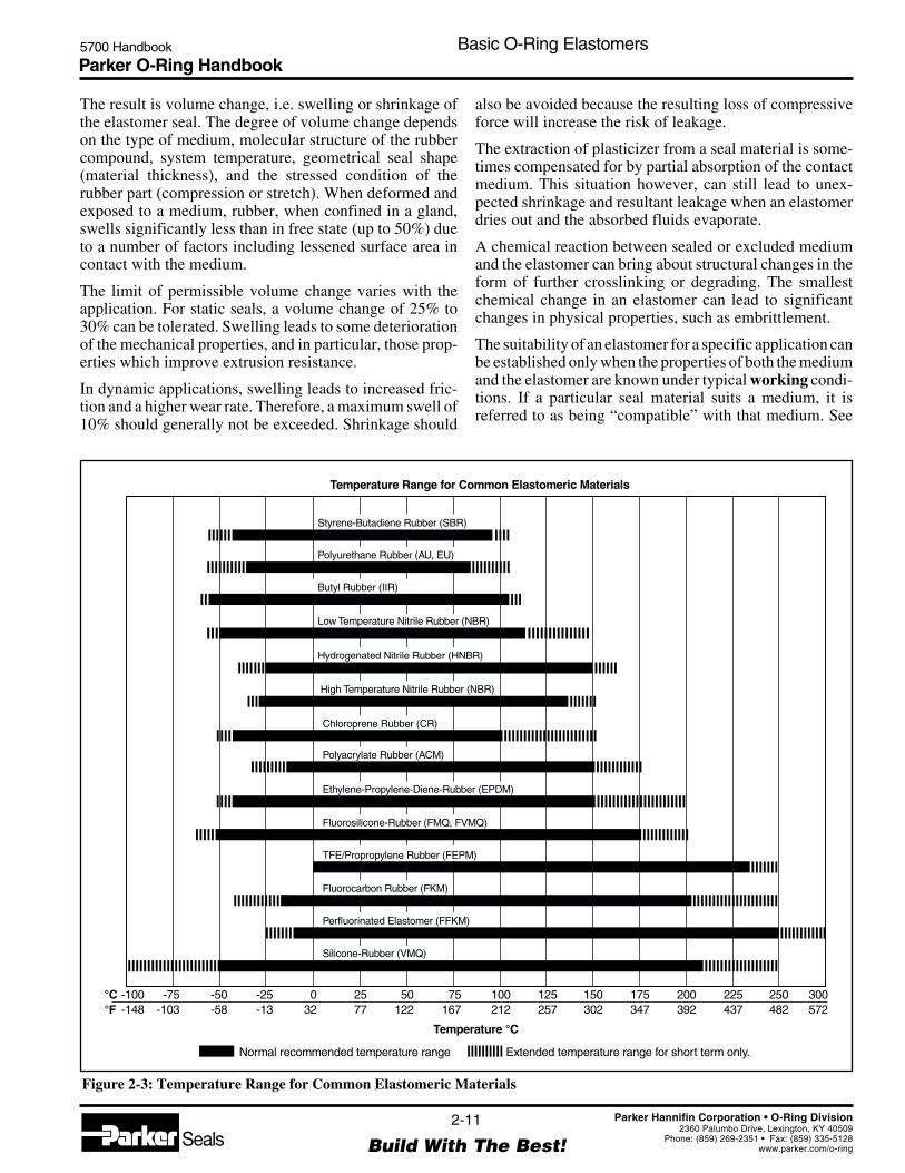
Figure 2-3: Temperature Range for Common Elastomeric Materials
-100-148
-75-103
-50-58
-25-13
032
2577
50122
75167
100212
Temperature °C
125257
150302
175347
200392
225437
250482
300572
Normal recommended temperature range Extended temperature range for short term only.
Styrene-Butadiene Rubber (SBR)
Polyurethane Rubber (AU, EU)
Butyl Rubber (IIR)
Low Temperature Nitrile Rubber (NBR)
High Temperature Nitrile Rubber (NBR)
Hydrogenated Nitrile Rubber (HNBR)
Chloroprene Rubber (CR)
Polyacrylate Rubber (ACM)
Ethylene-Propylene-Diene-Rubber (EPDM)
Fluorosilicone-Rubber (FMQ, FVMQ)
TFE/Propropylene Rubber (FEPM)
Fluorocarbon Rubber (FKM)
Perfluorinated Elastomer (FFKM)
Silicone-Rubber (VMQ)
Temperature Range for Common Elastomeric Materials
°C°F
The result is volume change, i.e. swelling or shrinkage ofthe elastomer seal. The degree of volume change dependson the type of medium, molecular structure of the rubbercompound, system temperature, geometrical seal shape(material thickness), and the stressed condition of therubber part (compression or stretch). When deformed andexposed to a medium, rubber, when confined in a gland,swells significantly less than in free state (up to 50%) dueto a number of factors including lessened surface area incontact with the medium.
The limit of permissible volume change varies with theapplication. For static seals, a volume change of 25% to30% can be tolerated. Swelling leads to some deteriorationof the mechanical properties, and in particular, those prop-erties which improve extrusion resistance.
In dynamic applications, swelling leads to increased fric-tion and a higher wear rate. Therefore, a maximum swell of10% should generally not be exceeded. Shrinkage should
also be avoided because the resulting loss of compressiveforce will increase the risk of leakage.
The extraction of plasticizer from a seal material is some-times compensated for by partial absorption of the contactmedium. This situation however, can still lead to unex-pected shrinkage and resultant leakage when an elastomerdries out and the absorbed fluids evaporate.
A chemical reaction between sealed or excluded mediumand the elastomer can bring about structural changes in theform of further crosslinking or degrading. The smallestchemical change in an elastomer can lead to significantchanges in physical properties, such as embrittlement.
The suitability of an elastomer for a specific application canbe established only when the properties of both the mediumand the elastomer are known under typical working condi-tions. If a particular seal material suits a medium, it isreferred to as being “compatible” with that medium. See
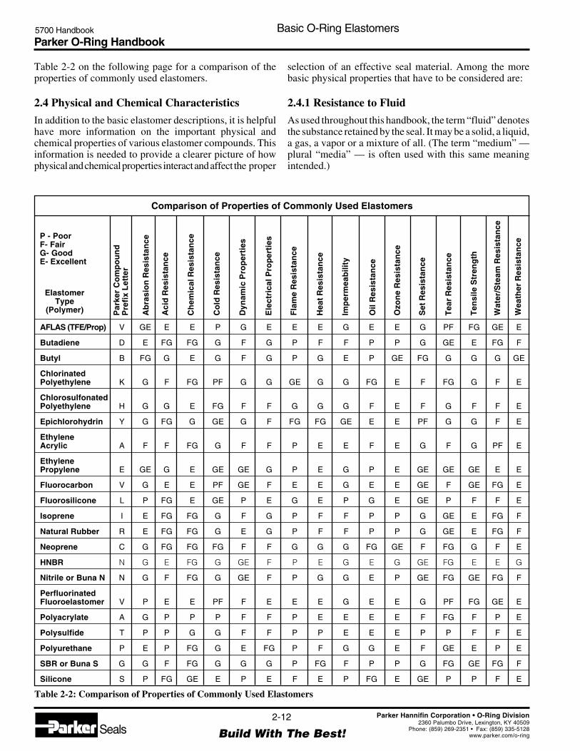
Parker O-Ring Handbook5700 Handbook Basic O-Ring Elastomers
2-12
Build With The Best!SealsParker Hannifin Corporation • O-Ring Division
2360 Palumbo Drive, Lexington, KY 40509Phone: (859) 269-2351 • Fax: (859) 335-5128
www.parker.com/o-ring
AFLAS (TFE/Prop) V GE E E P G E E E G E E G PF FG GE E
Butadiene D E FG FG G F G P F F P P G GE E FG F
Butyl B FG G E G F G P G E P GE FG G G G GE
ChlorinatedPolyethylene K G F FG PF G G GE G G FG E F FG G F E
ChlorosulfonatedPolyethylene H G G E FG F F G G G F E F G F F E
Epichlorohydrin Y G FG G GE G F FG FG GE E E PF G G F E
EthyleneAcrylic A F F FG G F F P E E F E G F G PF E
EthylenePropylene E GE G E GE GE G P E G P E GE GE GE E E
Fluorocarbon V G E E PF GE F E E G E E GE F GE FG E
Fluorosilicone L P FG E GE P E G E P G E GE P F F E
Isoprene I E FG FG G F G P F F P P G GE E FG F
Natural Rubber R E FG FG G E G P F F P P G GE E FG F
Neoprene C G FG FG FG F F G G G FG GE F FG G F E
HNBR N G E FG G GE F P E G E G GE FG E E G
Nitrile or Buna N N G F FG G GE F P G G E P GE FG GE FG F
PerfluorinatedFluoroelastomer V P E E PF F E E E G E E G PF FG GE E
Polyacrylate A G P P P F F P E E E E F FG F P E
Polysulfide T P P G G F F P P E E E P P F F E
Polyurethane P E P FG G E FG P F G G E F GE E P E
SBR or Buna S G G F FG G G G P FG F P P G FG GE FG F
Silicone S P FG GE E P E F E P FG E GE P P F E
Par
ker
Co
mp
ou
nd
Pre
fix
Let
ter
Ab
rasi
on
Res
ista
nce
Aci
d R
esis
tan
ce
Ch
emic
al R
esis
tan
ce
Co
ld R
esis
tan
ce
Dyn
amic
Pro
per
ties
Ele
ctri
cal P
rop
erti
es
Fla
me
Res
ista
nce
Hea
t Res
ista
nce
Imp
erm
eab
ility
Oil
Res
ista
nce
Ozo
ne
Res
ista
nce
Set
Res
ista
nce
Tea
r R
esis
tan
ce
Ten
sile
Str
eng
th
Wat
er/S
team
Res
ista
nce
Wea
ther
Res
ista
nce
ElastomerType
(Polymer)
Comparison of Properties of Commonly Used Elastomers
P - PoorF- FairG- GoodE- Excellent
Table 2-2: Comparison of Properties of Commonly Used Elastomers
Table 2-2 on the following page for a comparison of theproperties of commonly used elastomers.
2.4 Physical and Chemical Characteristics
In addition to the basic elastomer descriptions, it is helpfulhave more information on the important physical andchemical properties of various elastomer compounds. Thisinformation is needed to provide a clearer picture of howphysical and chemical properties interact and affect the proper
selection of an effective seal material. Among the morebasic physical properties that have to be considered are:
2.4.1 Resistance to Fluid
As used throughout this handbook, the term “fluid” denotesthe substance retained by the seal. It may be a solid, a liquid,a gas, a vapor or a mixture of all. (The term “medium” —plural “media” — is often used with this same meaningintended.)

Parker O-Ring Handbook5700 Handbook Basic O-Ring Elastomers
2-13
Build With The Best!SealsParker Hannifin Corporation • O-Ring Division
2360 Palumbo Drive, Lexington, KY 40509Phone: (859) 269-2351 • Fax: (859) 335-5128
www.parker.com/o-ring
The chemical effect of the fluid on the seal is of primeimportance. The fluid must not alter the operational char-acteristics or reduce the life expectancy of the seal signifi-cantly. Excessive chemical deterioration of the seal must beavoided. It is easy, however, to be misled on this point. Asignificant amount of volume shrinkage usually results inpremature leakage of any O-ring seal, whether static ordynamic. On the other hand, a compound that swellsexcessively in a fluid, or develops a large increase ordecrease in hardness, tensile strength, or elongation, willoften continue to serve well for a long time as a static sealin spite of such undesirable conditions.
2.4.2 Hardness
Throughout the seal industry, the Shore A type durometerscale, manufactured by a variety of manufacturers, is thestandard instrument used to measure the hardness of mostrubber compounds. It should be noted that there are otherhardness scales used to describe elastomers (B, C, D, DO,O, OO) but these are typically not used by the seal industry.
The durometer has a calibrated spring which forces anindentor point into the test specimen against the resistanceof the rubber. There is an indicating scale on which thehardness is then read directly. It is calibrated to read 100 ifthere is no penetration, as on a flat glass or steel surface.(For specimens that are too thin or provide too small an areafor accurate durometer readings, Micro Hardness Testing isrecommended).
In the O-ring industry there is another hardness scale that isused due to the curved surface of the O-ring cross-sectioncausing problems with accurately reading Shore A. Thescale is IRHD (International Rubber Hardness Degrees).The size and shape of the indentor used in IRHD readingsis much smaller, thus allowing for more accurate measure-ments on curved surfaces such as an O-ring cross-section.Unfortunately, there is not a direct correlation between thereadings of Shore A and IRHD Scales.
Softer sealing materials, with lower hardness readings, willflow more easily into the microfine grooves and imperfec-tions of the mating parts (the gland, bore, rod or sealflanges). This is particularly important in low-pressureseals because they are not activated by fluid pressure.Conversely, the harder materials offer greater resistance toextrusion. Referring back to the O-ring seal diagrams,Figures 1-4 through 1-7, it can be seen that a harder O-ringwill have greater resistance to extrusion into the narrow gapbetween the piston and bore. There are certain applicationsin which the compressive load available for assembly islimited. In these situations, Figures 2-4 through 2-8 arehelpful, providing compression load requirements forO-rings of different hardnesses, for each of the five stan-dard O-ring cross-sections.
In dynamic applications, the hardness of the O-ring isdoubly important because it also affects both breakout andrunning friction. Although a harder compound will, ingeneral, have a lower coefficient of friction than a softermaterial, the actual running and breakout friction values areactually higher because the compressive load required toachieve the proper squeeze and force the harder materialinto a given O-ring cavity is so much greater.
For most applications, compounds having a Shore A durom-eter hardness of 70 to 80 is the most suitable compromise.This is particularly true of dynamic applications where 90durometer or harder compounds often allow a few drops offluid to pass with each cycle, and 50 durometer compoundstend to abrade, wear, and extrude very quickly.
Normally durometer hardness is referred to in incrementsof five or ten, as 60 durometer, 75 durometer, etc. — not as62 durometer, 66 durometer or 73 durometer. This practiceis based on:
(1) the fact that durometer is generally called out inspecifications with a tolerance of ±5 (i.e., 65±5,70±5, 90±5);
(2) the inherent minor variance from batch to batch of agiven rubber compound due to slight differences inraw materials and processing techniques; and
(3) the human variance encountered in reading durom-eter hardness. On a 70-durometer stock, for example,one person might read 69 and another 71. This smalldifference is to be expected and is considered to bewithin acceptable experimental error and the accu-racy of the testing equipment.
2.4.3 Toughness
Toughness is not a measured property or parameter butrather a qualitative term frequently used to summarize thecombination of resistance to physical forces other thanchemical action. It is used as a relative term in practice. Thefollowing six terms (paragraphs 2.4.4 through 2.4.9) aremajor indicators of, and describe the “toughness” of acompound.
2.4.4 Tensile Strength
Tensile strength is measured as the psi (pounds per squareinch) or MPa (Mega Pascals) required to rupture a speci-men of a given elastomer material when stressed. Tensilestrength is one quality assurance measurement used toinsure compound uniformity. It is also useful as an indica-tion of deterioration of the compound after it has been incontact with a fluid for long periods. If fluid contact resultsin only a small reduction in tensile strength, seal life maystill be relatively long, yet if a large reduction of tensilestrength occurs, seal life may be relatively short. Excep-tions to this rule do occur. Tensile strength is not a proper

Parker O-Ring Handbook5700 Handbook Basic O-Ring Elastomers
2-14
Build With The Best!SealsParker Hannifin Corporation • O-Ring Division
2360 Palumbo Drive, Lexington, KY 40509Phone: (859) 269-2351 • Fax: (859) 335-5128
www.parker.com/o-ring
Figure 2-4: .070 Cross Section
Figure 2-5: .103 Cross Section
.103 Cross Section
Compression Load per Linear Inch of Seal — Pounds
.1
40%
30%
20%
10%
5%
.2 .3 .4 .5 .6 .7.8 2 2 23 3 34 4 45 5 56 6 67 7 78 8 89 9 910 100 1000.91
Per
cent
Com
pres
sion
70
70
70
60
60
60
50
50
50
80
9080
90
50
9080
7060
50
Shore
A H
ardn
ess
9080
90
8070
60
.070 Cross Section
Compression Load per Linear Inch of Seal — Pounds
.1
40%
9080
80
30%
20%
10%
5%
.2 .3 .4 .5 .6 .7.8 2 2 23 3 34 4 45 5 56 6 67 7 78 8 89 9 910 100 1000.91
Per
cent
Com
pres
sion
70
70
70
70
60
60
60
50
50
50
80
9080
90
6050
9080
7060
50
Shore
A H
ardn
ess
90

Parker O-Ring Handbook5700 Handbook Basic O-Ring Elastomers
2-15
Build With The Best!SealsParker Hannifin Corporation • O-Ring Division
2360 Palumbo Drive, Lexington, KY 40509Phone: (859) 269-2351 • Fax: (859) 335-5128
www.parker.com/o-ring
Figure 2-7: .210 Cross Section
Figure 2-6: .139 Cross Section
.139 Cross Section
Compression Load per Linear Inch of Seal — Pounds
.1
40%
30%
20%
10%
5%
.2 .3 .4 .5 .6 .7.8 2 2 23 3 34 4 45 5 56 6 67 7 78 8 89 9 910 100 1000.91
Per
cent
Com
pres
sion
70
70
70
60
60
50
50
80
9080
90
6050
90
7060
50
Shore
A H
ardn
ess
9080
90
70
60
50
80
80
.1
40%
30%
20%
10%
5%
.2 .3 .4 .5 .6
Per
cent
Com
pres
sion
Compression Load per Linear Inch of Seal — Pounds
.7.8 2 2 23 3 34 4 45 5 56 6 67 7 78 8 89 9 910 100 1000.91
90
7060
50
80
.210 Cross Section
70
70
7060
50
50
9080
90
60
Shore
AHar
dnes
s
9080
90
70
60
50
80
60
80
50

Parker O-Ring Handbook5700 Handbook Basic O-Ring Elastomers
2-16
Build With The Best!SealsParker Hannifin Corporation • O-Ring Division
2360 Palumbo Drive, Lexington, KY 40509Phone: (859) 269-2351 • Fax: (859) 335-5128
www.parker.com/o-ring
Figure 2-8: .275 Cross Section
Compression Load per Linear Inch of Seal — Pounds
.1 .2 .3 .4 .5 .6 .7.8 2 2 23 3 34 4 45 5 56 6 67 7 78 8 89 9 910 100 1000.91
40%
30%
20%
10%
5%
Per
cent
Com
pres
sion
.275 Cross Section
70
70
7060
50
50
9080
90
90
7060
50
Shore
A H
ardn
ess
9080
90
70
60
50
80
80
60
80
5060
indication of resistance to extrusion, nor is it ordinarilyused in design calculations. However, in dynamic applica-tions a minimum of 1,000 psi (7 MPa) is normally neces-sary to assure good strength characteristics required forlong-term sealability and wear resistance in moving sys-tems.
2.4.5 Elongation
Elongation is defined as the increase in length, expressednumerically, as a percent of initial length. It is generallyreported as ultimate elongation, the increase over the origi-nal dimension at break. This property primarily determinesthe stretch which can be tolerated during the installation ofan O-ring. Elongation increases in importance as the diam-eters of a gland become smaller. It is also a measure of theability of a compound to recover from peak overload, or aforce localized in one small area of a seal, when consideredin conjunction with tensile strength. An adverse change inthe elongation of a compound after exposure to a fluid is adefinite sign of degradation of the material. Elongation,like tensile strength, is used throughout the industry as aquality assurance measure on production batches of elas-tomer materials.
2.4.6 O-Ring Compression Force
O-ring compression force is the force required to compressan O-ring the amount necessary to maintain an adequate
sealing line of contact. See Figures 2-4 through 2-8. It isvery important in some applications, particularly in face-type seals where the available compression load is limited.The factors that influence compression force for a givenapplication, and a method of finding its approximate mag-nitude are explained in Section III, O-Ring Applications.
2.4.7 Modulus
Modulus, as used in rubber terminology, refers to stress ata predetermined elongation, usually 100%. It is expressedin pounds per square inch (psi) or MPa (Mega Pascals).This is actually the elastic modulus of the material.
The higher the modulus of a compound, the more apt it isto recover from peak overload or localized force, and thebetter its resistance to extrusion. Modulus normally in-creases with an increase in hardness. It is probably the bestoverall indicator of the toughness of a given compound, allother factors being equal. It is also used as a qualityassurance measure because it tends to be much moreconsistent, batch to batch, than either tensile strength orelongation.
2.4.8 Tear Resistance
Tear strength is relatively low for most compounds.However, if it is extremely low (less than 100 lbs./in.)(17.5 kn/m) , there is increased danger of nicking or cutting

Parker O-Ring Handbook5700 Handbook Basic O-Ring Elastomers
2-17
Build With The Best!SealsParker Hannifin Corporation • O-Ring Division
2360 Palumbo Drive, Lexington, KY 40509Phone: (859) 269-2351 • Fax: (859) 335-5128
www.parker.com/o-ring
the O-ring during assembly, especially if it must pass overports, sharp edges or burrs. Compounds with poor tearresistance will fail quickly under further flexing or stressonce a crack is started. In dynamic seal applications,inferior tear strength of a compound is also indicative ofpoor abrasion resistance which may lead to premature wearand early failure of the seal. Usually however, this propertyneed not be considered for static applications.
2.4.9 Abrasion Resistance
Abrasion resistance is a general term that indicates the wearresistance of a compound. Where “tear resistance” essen-tially concerns cutting or otherwise rupturing the surface,“abrasion resistance” concerns scraping or rubbing of thesurface. This is of major importance for dynamic sealmaterials. Only certain elastomers are recommended fordynamic O-ring service where moving parts actually con-tact the seal material. Harder compounds, up to 90 durom-eter, are normally more resistant to abrasion than softercompounds. Of course, as with all sealing compromises,abrasion resistance must be considered in conjunction withother physical and chemical requirements.
2.4.10 Volume Change
Volume change is the increase or decrease of the volume ofan elastomer after it has been in contact with a fluid,measured in percent (%).
Swell or increase in volume is almost always accompaniedby a decrease in hardness. As might be surmised, excessiveswell will result in marked softening of the rubber. Thiscondition will lead to reduced abrasion and tear resistance,and may permit extrusion of the seal under high pressure.
For static O-ring applications volume swell up to 30% canusually be tolerated. For dynamic applications, 10 or 15%swell is a reasonable maximum unless special provisionsare made in the gland design itself. This is a rule-of-thumband there will be occasional exceptions to the rule.
Swell may actually augment seal effectiveness under somecircumstances. For instance, (1) swell may compensate forcompression set. If a seal relaxes 15% and swells 20%, therelaxation (compression set) tends to be canceled by the
swell (see Table 2-3), (2) absorbed fluid may have some-what the same effect on a compound as the addition ofplasticizers, softening and thus providing more seal flex-ibility at the low temperature end of its operating range.These “potential” good effects however, should not berelied on when choosing a compound for an application.Awareness of these facts is of interest as they can andfrequently do contribute to enhanced seal performance.The amount of volume swell after long-term immersion —stabilized volume — is seldom reported because it takesseveral readings to identify. The usual 70-hour ASTMimmersion test will indicate a swelling effect, whereas along-term test shows shrinkage. Thus swell indicated byshort-term testing may only be an interim condition.
Shrinkage or decrease in volume is usually accompanied byan increase in hardness. Also, just as swell compensates forcompression set, shrinkage will intensify the compressionset effect causing the seal to pull away from sealingsurfaces, thus providing a leak path. It is apparent then, thatshrinkage is far more critical than swell. More than 3 or 4%shrinkage can be serious for moving seals. In some in-stances, fluids present may extract plasticizers, causing theseal to shrink when the fluid is temporarily removed fromcontact with the seal, as by draining a valve body (dry- outshrinkage). Such shrinkage may or may not be serious;depending on its magnitude, gland design, and the degreeof leakage tolerable before the seal re-swells and regains itssealing line of contact. However, even if the seal does re-swell there is the danger that it may not properly reseatitself. If any shrinkage is a possibility in an application, itmust be considered thoroughly and carefully.
2.4.11 Compression Set
Compression set is generally determined in air aging andreported as the percent of deflection by which the elastomerfails to recover after a fixed time under specified squeezeand temperature. Zero percent (0%) indicates no relaxationhas occurred whereas 100% indicates total relaxation; theseal just contacts mating surfaces but no longer exerts aforce against those surfaces.
Compression set may also be stated as a percent of originalthickness. However, percent of original deflection is morecommon. See Figure 2-9.
Although it is generally desirable to have low compressionset properties in a seal material, this is not so critical as itmight appear from a practical design standpoint, because ofactual service variables. It is easy to go overboard on thisproperty from a theoretical standpoint. Remember that agood balance of all physical properties is usually necessaryfor optimum seal performance. This is the eternal sealingcompromise the seal designer always faces.
For instance, a seal may continue to seal after taking a 100%compression set provided temperature and system pressure
Compression Set vs. Volume Change
Parker Compound: Butyl Temperature: 74°C (165°F)Time: 168 hrs. Deflection used: 25%
Air Fluorolube Fluoroester
Volume Change % 0 +19.5 -0.4
Set % of OriginalDeflection 25.4 0 20.7
Table 2-3: Compression Set vs. Volume Change

Parker O-Ring Handbook5700 Handbook Basic O-Ring Elastomers
2-18
Build With The Best!SealsParker Hannifin Corporation • O-Ring Division
2360 Palumbo Drive, Lexington, KY 40509Phone: (859) 269-2351 • Fax: (859) 335-5128
www.parker.com/o-ring
Figure 2-11: Compression Set NBR 70
100
90
Relationship between Compression set,deformation and cross-section
80
70
1
2
3
60
50
40
30
20
10
10 20 30 40
Compression SetTest at
T = 100°C (212°F)t = 70 h
Cross-Section1 = 1.80 mm (.07 in.)2 = 3.55 mm (.14 in.)3 = 7.00 mm (.28 in.)
^
^
^
Com
pres
sion
Set
(%)
Cross-Section Deformation (%)
Nitrile-Butadiene
NBR 70
Compression Set NBR 70
Figure 2-10: Compression Set VMQ 70
100
90
Relationship between Compression set,deformation and cross-section
80
70
1
2
60
50
40
30
20
10
10 20 30 40
Compression SetTest at
T = 100°C (212°F)t = 70 h
Cross-Section1 = 1.80 mm (.07 in.)2 = 7.00 mm (.28 in.)^
^
Com
pres
sion
Set
(%)
Cross-Section Deformation (%)
SiliconeVMQ 70
Compression Set VMQ 70
remain steady and no motion or force causes a break in theline of seal contact. Also, as mentioned previously, swell-ing caused by contact with the service fluid may compen-sate for compression set. Table 2-3 shows the results of alaboratory test that illustrates this phenomenon.
Note that in air and in the fluid that caused slight shrink-age, the compound took a set of approximately 20 to 25%.In the fluid that caused a 20% swell, there was no measur-able compression set. The condition most to be feared isthe combination of high compression set and shrinkage.This will always lead to seal failure unless exceptionallyhigh squeeze is employed. See Figures 2-10 through 2-13.
Figure 2-9: Compression Set
Deflection = t -to s Return CompressionSet = t -to i
OriginalThickness
to
RecoveredThickness
ti
SpacerBar
Example: t = 0.200 t = 0.150 t = 0.190o s i Compression Set (As Percent of Original Deflection)
(ASTM normally requiresdeflection equal to 1/4 t )o
C =
C =
X 100
X 100 =20% Compression Set=
t - to i
0.200 - 0.190 0.0100.0500.200 - 0.150
t - to s

Parker O-Ring Handbook5700 Handbook Basic O-Ring Elastomers
2-19
Build With The Best!SealsParker Hannifin Corporation • O-Ring Division
2360 Palumbo Drive, Lexington, KY 40509Phone: (859) 269-2351 • Fax: (859) 335-5128
www.parker.com/o-ring
Figure 2-12: Compression Set vs. NBR 70 Compounds
Figure 2-13: Compression Set vs. Polymer Family
1
2
50
40
30
20
10
100212
125257
150302
Compression SetTest at
t = 70 h
O-Ring Cross-SectionDeformed by 25%Cross-Section = 3.55 mm
(.14 in.)
NBR 70-1(Normal Temperature NBR)NBR 70-2(High Temperature NBR)
Com
pres
sion
Set
(%)
Test Temperature
°C°F
Compression Set
100
90
Compression SetAgainst Temperature
80
70
1
2 43
60
50
40
30
20
10
100 125 150 175 200
Compression SetTest at
t = 70 h
O-Ring Cross-SectionDeformed by 25%Cross-Section = 3.55 mm
(.14 in.)
FKM — 1ACM — 2EPDM — 3VMQ — 4
Com
pres
sion
Set
(%)
Compression Set
100212 257 302 347 392
Test Temperature
°C°F
2.4.12 Thermal Effects
All rubber is subject to deterioration at high temperature.Volume change and compression set are both greatly influ-enced by heat. Hardness is influenced in a rather complexway. The first effect of increased temperature is to softenthe compound. This is a physical change, and will reversewhen the temperature drops. However, it must be consid-ered in high pressure applications because a compound thatis sufficiently hard to resist extrusion at room temperature
may begin to flow and extrude through the clearance gap asthe temperature rises, due to this softening effect.
With increasing time at high temperature, chemical changesslowly occur. These generally cause an increase in hard-ness, along with volume and compression set changes asmentioned above. Changes in tensile strength and elonga-tion are also involved. Being chemical in nature, thesechanges are not reversible.
With the exception of the cryogenics field, the tendency isto overlook the effects of low temperatures on elastomericseal compounds as they are generally reversible as thetemperature rises.
Any changes induced by low temperature are primarilyphysical and, as stated, are reversible. An elastomer willalmost completely regain its original properties whenwarmed. There are several tests that are used to define lowtemperature characteristics of a compound, but there doesnot seem to be much correlation among them. Perhaps thebest of the low temperature tests is TR-10 or TemperatureRetraction Test.
The TR-10 test results are easily reproducible, For thisreason the TR-10 is used extensively in many differentspecifications, not only for assuring low temperature per-formance but occasionally as a quality assurance measureas well. From experience, we have found that most com-pounds will provide effective sealing at 8°C (15°F) belowtheir TR-10 temperature values. However, careful study ofthe paragraphs on “temperature” later in this section and inSection III should be made before selecting a compound forlow temperature service.
If low pressures are anticipated at low temperature, hard-ness should be considered along with the low temperatureproperties of the compound. As temperature decreases,hardness increases. Low pressures require a soft materialthat can be easily deformed as it is forced against matingsurfaces. It is possible that a 70 durometer compound atroom temperature might harden to 85 durometer at -34°C(-30°F) for example, and fail to respond to low pressure atthis temperature.
On the other hand, the same type of compound with 40durometer hardness at room temperature may register only75 durometer at -34°C (-30°F) and provide somewhatbetter response. In moderate pressure service, low tempera-ture hardness increase is seldom of consequence. However,hardness is only one of several factors to consider when lowtemperature performance is involved.
Flexibility, resilience, compression set and brittleness areperhaps more basic criteria for sealing at low temperaturethan measured hardness. This may be demonstrated byreference to Figure 2-14 that shows the variation in hard-ness for several elastomers at low temperatures.

Parker O-Ring Handbook5700 Handbook Basic O-Ring Elastomers
2-20
Build With The Best!SealsParker Hannifin Corporation • O-Ring Division
2360 Palumbo Drive, Lexington, KY 40509Phone: (859) 269-2351 • Fax: (859) 335-5128
www.parker.com/o-ring
It is significant that many of the materials for whichhardness is plotted in Figure 2-14 are considered good forseal service at temperatures considerably below that atwhich durometer hardness tends to reach a maximum. Thisclearly illustrates that durometer measurements alone arenot reliable determinants of low temperature seal perfor-mance. The swelling or shrinkage effect of the fluid beingsealed must also be taken into account. If the seal swells, itis absorbing fluids which may act in much the same way asa low temperature plasticizer, allowing the seal to remainmore flexible at low temperature than was possible beforethe absorption of the fluid.
If the seal shrinks, something is being extracted from thecompound. The greater part of the leached material isusually the plasticizer provided by the compounder for lowtemperature flexibility. This being the case, the seal maynow lose some of its original flexibility at low temperature.It may become stiff at a temperature 2°C to 5°C (5°F to10°F) higher than that at which it is rated.
Crystallization is another side effect of low temperatureoperation that must be considered, especially for dynamicapplications. (Crystallization is the re-orientation of mo-lecular segments causing a change of properties in thecompound). When a compound crystallizes it becomesrigid and has none of the resilience that is so necessary foran effective seal.
This phenomenon manifests itself as a flat spot on theO-ring and is sometimes misinterpreted as compression set.The flatness will gradually disappear and the seal willregain its original resilience upon warming. Initially, it maytake two or three months for a compound to crystallize at alow or moderate temperature. However, on succeeding
exposures to low temperature, crystallization sets in muchmore rapidly.
The end result of crystallization is seal leakage. Forexample, seals which have been known to function satisfac-torily in an air conditioning unit through the first summer,have failed during storage because the system was notturned on to pressurize the seals through a long, cold winter.One way to test for the crystallization effect is to use adouble temperature drop. After conditioning at a moder-ately low temperature for a long period — say two months— temperature is lowered another 30°C (86°F) or so andleakage checked at .7 to 1.4 Bar (10 to 20 PSI) pressure.Certain types of polychloroprene (Neoprene) have a pro-nounced tendency to crystallize. Spring-loading the sealcan compensate for crystallization.
2.4.13 Resilience
Resilience is essentially the ability of a compound to returnquickly to its original shape after a temporary deflection.Reasonable resilience is vital to a moving seal. Resilienceis primarily an inherent property of the elastomer. It can beimproved somewhat by compounding. More important, itcan be degraded or even destroyed by poor compoundingtechniques. It is very difficult to create a laboratory testwhich properly relates this property to seal performance.Therefore, compounding experience and functional testingunder actual service conditions are used to insure adequateresilience.
2.4.14 Deterioration
This term normally refers to chemical change of an elas-tomer resulting in permanent loss of properties. It is not tobe confused with reversible or temporary property losses.Both permanent and temporary property losses may beaccompanied by swell. The temporary condition is due tophysical permeation of fluid without chemical alteration.
2.4.15 Corrosion
Corrosion is the result of chemical action of a fluid and/orthe elastomer compound upon the metal surfaces of the sealgland cavity. This handbook is primarily concerned withcorrosive effects caused by the compound alone, althoughit should be noted that fluid corrosion of the gland metalwill cause a change of surface finish that can seriouslyaffect the seal, especially in a dynamic application. Whenrubber seals were first used, there were numerous instancesin which the compound itself did act adversely upon metalcausing actual pitting of the gland surface. Certain elas-tomer compounding ingredients, such as uncombined sul-fur or certain types of carbon black were found to cause theproblem.
Figure 2-14: Effect of Low Temperature on RubberHardness
Fluorosilicone
Nitrile
NitrileNeoprene
Silicone
Ethylene-Propylene
Fluorocarbon
Nitrile
-70-57
-60-51
-50-46
-40-40
-30-34
30-1
404
5010
6016
70 8021 27
50
55
60
65
70
75
80
85
90
95
100
-20-29
20-7
-10-23
10-12
0-18
Temperature°C°F
Har
dnes
s,S
hore
A S
cale
Effects of Low Temperature on Rubber Hardness
Parker O-Ring Handbook5700 Handbook Basic O-Ring Elastomers
2-21
Build With The Best!SealsParker Hannifin Corporation • O-Ring Division
2360 Palumbo Drive, Lexington, KY 40509Phone: (859) 269-2351 • Fax: (859) 335-5128
www.parker.com/o-ring
Currently, compounding expertise, modern chemicals andsupplier testing has made reports of this type of corrosionrare. However, due to frequent introduction of new andimproved compounding ingredients, continuous attentionto potential corrosive effects is necessary.
A. Corrosion Caused by Free Sulphur — Rubber com-pounds often are vulcanized using an accelerator contain-ing the element sulfur. A large percentage of the sulfurunder the influence of heat (vulcanization) forms bridges(cross-links) between the elastomer molecule chains. Thissulfur remains chemically fixed and cannot be extracted.However a smaller portion of the sulfur remains free andnot fixed in the elastomer structure.
Free sulfur in contact with many metals and alloys (e.g.silver, copper, lead) tends to form metal sulfides whichcause discoloring and corrosion damage. Further, a reac-tion between metal and sulfur can lead to the failure of adynamic seal if rubber adheres to the metal surface after along downtime. In all cases where there is dynamic actionexpected at the seal interface, use of a sulfur-free com-pound is recommended.
B. Corrosion Caused by the Formation of HydrochloricAcid — Hydrochloric (HCl) acid can be formed in certainenvironmental conditions when free chloride is present inan elastomer.
Compounds in the CR, ECO, CO and to a lesser extent inACM polymer groups tend to cause corrosion if the formuladoes not contain sufficient amounts of inhibitors and stabi-lizers (e.g. metal oxides) which retard free chloride. Hydro-chloric acid also can be formed around compounds whichare free from chloride (e.g. SBR, NR) if they containchloro-paraffin combinations which are used as flameretardants.
C. Electrochemical Corrosion — The formation of smallgalvanic cells is the main mechanism responsible for cor-rosion of metals. A galvanic cell is formed across twodissimilar metals. An electrolyte is required for the func-tion of a galvanic cell. Alloys made up from different metalphases or crystals can be damaged when small local cellsare formed.
Electrochemical corrosion in the zone of a sealing element(e.g. an O-ring) does not necessarily mean that the elas-tomer is always the cause. It is very difficult to say how farelectrochemical corrosion depends on the elastomer. It isgenerally assumed that condensate accumulates betweenthe rubber and the metal which, together with other impu-rities, causes electrochemical corrosion. The propensity tocorrode depends on the type of metal alloy(s), surfaceroughness, state of the metal, temperature and humidity.
2.4.16 Permeability
Permeability is the tendency of gas to pass or diffusethrough the elastomer. This should not be confused withleakage which is the tendency of a fluid to go around theseal. Permeability may be of prime importance in vacuumservice and some few pneumatic applications involvingextended storage but is seldom consequential in otherapplications. It should be understood that permeabilityincreases as temperatures rise, that different gases havedifferent permeability rates, and that the more a seal iscompressed, the greater its resistance to permeability.Refer to O-Ring Applications, Section III for additionalinformation on permeability and vacuum service.
2.4.17 Joule Effect
If a freely suspended rubber strip is loaded and stretchedand subsequently heated, the strip will contract and lift theload. Conversely, an unloaded strip when heated expandsto the coefficient of expansion for that rubber. This phe-nomenon of contraction is termed the Joule effect andoccurs only when heating a stretched rubber object.
Example: O-ring as radial shaft seal. The O-ring with aninner diameter smaller than the shaft is fitted under tension.The O-ring heats up due to friction and contracts. The resultis increased friction and temperature. Failure of the O-ringis characterized by a hard, brittle O-ring surface.
In practice an O-ring of larger inner diameter must there-fore be selected. An inner diameter between 1% to 3%larger than the shaft is recommended and the outer diameterof the gland should ensure that the O-ring is compressed onthe shaft surface.
The width of the gland should be slightly less than the cross-section diameter. The O-ring always should be fitted intothe bore and never on to the shaft.
2.4.18 Coefficient of Friction
Coefficient of friction of a moving elastomer seal relates toa number of factors including material hardness, lubrica-tion and surface characteristics of surrounding materials.Generally, breakout friction is many times that of runningfriction. This varies with several factors, primarily hard-ness of the seal material. When only the hardness is changed,an increase in hardness will increase breakout frictionwhile a decrease will lower breakout friction. In thoseinstances where seal external lubrication is impossible,Parker offers several compounds having self-containedlubricants. These compounds are also desirable wherecontinuous presence of a lubricant is uncertain, and whereminimal friction is essential. For more friction data see O-Ring Applications and Dynamic O-Ring Sealing, Sections IIIand V, respectively.

Parker O-Ring Handbook5700 Handbook Basic O-Ring Elastomers
2-22
Build With The Best!SealsParker Hannifin Corporation • O-Ring Division
2360 Palumbo Drive, Lexington, KY 40509Phone: (859) 269-2351 • Fax: (859) 335-5128
www.parker.com/o-ring
2.4.19 Electrical Properties
Elastomers may be good insulators, semiconductors orconductors. The type of material and compound (electri-cally conductive carbon black) are selected to electricalrequirements criteria:
Electrically insulating: > 109 ohms-cm - SBR, IIR,EPDM, VMQ, FKM.Anti-static, as semiconductor: 105 to 109 ohms-cm -NBR, CR.Electrically conductive: < 105 ohms-cm - SpecialCompounds. See Parker Chomerics Division.
Many elastomers must be minimally conductive to preventelectrostatic charging, e.g. fuel tank seals, drive belts,medical equipment, etc. When special conductive com-pounds are required, care should be taken to ensure thatconductive parts of the compound formula will not bedissolved or extracted by the medium being sealed, thuschanging the electrical properties. See Figure 2-15.
For shielding purposes against electromagnetic interfer-ence (EMI), compounds filled with conductive-particleshave been developed with a volume resistivity of < 10-2
Ohm- cm.
Please contact Parker regarding any special compoundrequirements and specific physical properties when con-templating the use of conductive elastomers. For morein-depth information on conductive elastomers and EMIshielding, see Parker Chomerics product information.
2.4.20 Coefficient of Thermal Expansion
Coefficient of linear expansion is the ratio of the change inlength per °C to the length at 0°C. Coefficient of volumetricexpansion for solids is approximately three times the linearcoefficient. As a rough approximation, elastomers have acoefficient of expansion ten times that of steel (an excep-tion to this is perfluoroelastomer). This can be a critical
Figure 2-16: Relative Force Produced by O-ring Swell
Relative Force Produced by O-ring SwellFor Different Compounds
Gland Void After Seal Compression — Percent
Forc
e
0 5 10 15 20 25 30 35 40 45 50
Linear Thermal Expansionof Typical Elastomers and Common Materials
Contraction Expansion24°C to -54°C 24°C to 191°C Coefficient(75°F to -65°F) (75° to 375°F) of Expansion
Material (in./ft.) (in./ft.) (in./in./°F)
Nitrile —General Purpose .108 .224 6.2 x 10⁻⁵
Neoprene .132 .274 7.6 x 10⁻⁵
FluorocarbonElastomer .156 .324 9.0 x 10⁻⁵
Kel-F .144 .299 8.3 x 10⁻⁵
Ethylene Propylene .155 .320 8.9 x 10⁻⁵
Silicone .174 .360 1.0 x 10⁻⁴
Low-TemperatureType Silicone .193 .396 1.1 x 10⁻⁴
Fluorosilicone N/A N/A 4.5 x 10⁻⁴
High-TemperatureType Aluminum,2017 .023 .047 1.3 x 10⁻⁵
Stainless Steel,Type 302 .017 .035 9.6 x 10⁻⁶
Steel, Mild .012 .024 6.7 x 10⁻⁶
Invar .001 .002 6.0 x 10⁻⁷
Table 2-4: Linear Thermal Expansion of TypicalElastomers and Common Materials
Figure 2-15: Specific Electrical Resistance (According toDIN 53596)
NBR
FKM
VMQ
EPDM
CR
Specific Electrical Resistance(according to DIN 53596)
102 104 106 108 1010 1012 1014 1016 1018 1020
Ohm-cm
factor at high temperature if the gland is nearly filled withthe seal, or at low temperature if squeeze is marginal. SeeTable 2-4.
There are certain reactions that in some circumstancescause a seal to exert relatively high forces against the sidesof a groove. These forces are generated by thermal expan-sion of the rubber and/or swelling effect of a fluid.
If the seal is completely confined and the gland is 100%filled, the dominating force is the force of thermal expan-sion of the rubber. There have been instances where a sealhas ruptured a steel gland due to expansion when heated.
Effective force exerted by the seal due to fluid swell isanother potentially large factor if the gland volume exceedsthat of the seal by only 5 to 10% (see Figure 2-16).Depending on the interaction between the rubber and thefluid being sealed, the effect may be quite pronounced evenat larger gland void conditions.

Parker O-Ring Handbook5700 Handbook Basic O-Ring Elastomers
2-23
Build With The Best!SealsParker Hannifin Corporation • O-Ring Division
2360 Palumbo Drive, Lexington, KY 40509Phone: (859) 269-2351 • Fax: (859) 335-5128
www.parker.com/o-ring
2.4.21 Effects on Properties
In some of the foregoing paragraphs, it has been mentionedthat various factors can alter the properties of rubbermaterials. Low temperatures cause reversible hardening ofcompounds, high temperatures may cause reversible andnon-reversible changes of many kinds, and exposure tofluids can effect all the properties of a rubber material.Besides these more-or-less obvious effects, there are manyadditional ways in which the properties of a compound maybe modified so that results by two different laboratoriesmay not agree. Knowledge of some of these pitfalls mayavoid misunderstandings.
2.5 Standard Test Procedures
There are standard ASTM procedures for conducting mostof the tests on rubber materials. It is important to followthese procedures carefully in conducting tests if uniformand repeatable results are to be obtained. For instance, inpulling specimens to find tensile strength, elongation, andmodulus values, ASTM D412 requires a uniform rate ofpull of 208 mm (20 inches) per minute. In one test, tensilestrength was found to decrease 5% when the speed wasreduced to 50.8 mm (2 inches) per minute, and it decreased30% when the speed was further reduced to 5.18 mm (0.2inches) per minute. Elongation and modulus values de-creased also, but by smaller amounts.
ASTM Compression Set D395 Test Method B, states, “Thepercentage of compression employed shall be approxi-mately 25% .” We have found significantly higher com-pression set values after compressing less than 25%, whileresults after 30 or 40% compression were sometimes smallerand sometimes greater than at 25%.
2.5.1 Test Specimens
ASTM test methods include descriptions of standard speci-mens for each test. Often, two or more specimens arerequired, but results from the different specimens willseldom agree. The way that properties vary with the size ofthe specimen is not consistent. For instance, as the cross-section increases, nitrile O-rings produce lower values oftensile strength, elongation, and compression set. Ethylenepropylene rings produce a similar pattern for tensile andelongation values but not compression set, while in fluoro-carbon compounds only the elongation shows this trend.
In fluid immersion tests, rings with smaller cross-sectionshave been found to swell more than larger rings. In observ-ing explosive decompression tests, the smaller cross-sec-tions had much better resistance to high-pressure gases.
When customers wish to monitor the Shore A hardness ofO-rings they purchase, they will sometimes order compres-sion set buttons from the same batch as the O-rings forpurposes of conducting hardness tests. This is becausedurometer hardness readings taken on actual O-rings are
notoriously variable. It is important, therefore, in reportingtest results, to include both a description of the test speci-mens used as well as describing the test method itself indetail.
2.5.2 Test Method Variables
More difficult to avoid are differences in test results due todifferences introduced by the human equation. In testingfor durometer hardness, for example, the presser foot of theinstrument is applied to the specimen “as rapidly as pos-sible without shock — Apply just sufficient pressure toobtain firm contact between presser foot and specimen.”Different operators will often disagree on the hardness of acompound because they use different speeds and differentamounts of pressure. In gauging the hardness of an O-ring,which has no flat surface, operators may vary in theaccuracy with which they apply the indentor to the actualcrown of the O-ring, the point that gives the most reliablereading. The only industry recognized test for hardness ofan O-ring is IRHD (see “Hardness” in this section).
In conducting the TR-10 low temperature test, the cold bathshould be warmed at the rate of 1°C (34°F) per minute. Anydifferent rate will result somewhat different readings.
2.5.3 Effects of Environment on Testing
High humidity in the air will reduce the tensile strength ofsome compounds. Changes in a fluid medium can occur inservice due to the effect of heat and contaminants. A rubberthat is virtually unaffected by new fluid may deteriorate inthe same fluid after it has been in service for a month. Testsare sometimes run in previously used fluid for this reason.
These are a but few examples to illustrate the fact that theproperties of rubber compounds are not constant. Theyvary according to the conditions under which they aretested, and some of the variables may be rather subtle.
2.6 Aging
Deterioration with time or aging relates to the basic natureof the rubber molecule. It is a long chain-like structureconsisting of many smaller molecules joined or linkedtogether. Points at which individual molecules join arecalled bonds. Bond sites and certain other areas may beparticularly susceptible to chemical reaction. At least threeprinciple types of such reactions are associated with aging.They usually occur concurrently, but in varying degrees:
a. Scission — The molecular bonds are cut, dividing thechain into smaller segments. Ozone, ultra-violet light, andradiation cause degradation of this type.
b. Crosslinking — An oxidation process whereby addi-tional intermolecular bonds are formed. This process maybe a regenerative one. Heat and oxygen are principle causesof this type of aging process.

Parker O-Ring Handbook5700 Handbook Basic O-Ring Elastomers
2-24
Build With The Best!SealsParker Hannifin Corporation • O-Ring Division
2360 Palumbo Drive, Lexington, KY 40509Phone: (859) 269-2351 • Fax: (859) 335-5128
www.parker.com/o-ring
c. Modification of Side Groups — A change in thecomplex, weaker fringe areas of the molecular constructiondue to chemical reaction. Moisture, for example, couldpromote this activity.
Note: all mechanisms by which rubber deteriorateswith time are attributable to environmental conditions.It is environment and not age that is significant to seallife, both in storage and actual service. While selectionand application of synthetic rubber seals to provideacceptable service life is the primary subject of thishandbook, our concern in the next paragraph will bewith seal life as it relates to storage conditions.
2.7 Storage
The effective storage life of an O-ring varies with theinherent resistance of each individual elastomer to normalstorage conditions. ARP 5316 places elastomers into threegroups according to “Age resistance generally associatedwith products fabricated from various rubbers.” Realizethat this document, ARP 5316, is an Aerospace Recom-mended Practice, not a standard that must be met.
Where non-age sensitive elastomers are involved, consid-erable storage life without detectable damage is commoneven under adverse conditions. For materials falling intothe 15 year category, which are subject to age deterioration,the following conditions are suggested for maximum life:
1. Ambient temperature not exceeding 49°C (120°F)2. Exclusion of air (oxygen)3. Exclusion of contamination4. Exclusion of light (particularly sunlight)5. Exclusion of ozone generating electrical devices6. Exclusion of radiation
Generally, sealed polyethylene bags stored in larger card-board containers or polyethylene lined craft paper bagsinsure optimal storage life. However, in normal warehous-ing conditions, life of even the relatively age-sensitiveelastomers is considerable. This is due to major improve-ments in modern compounding technique, and has beendocumented through a number of investigations concernedwith effects of long-term storage of elastomeric materialsundertaken in the recent past. These include controlledlaboratory studies of many years duration in addition toevaluation of seals recovered from salvaged World War IIaircraft and other sources after exposure to widely varyingconditions over many years.
2.8 Cure Date
To facilitate proper stock rotation on the shelves of Parkerdistributors and customers, Parker Seal supplies the curedate on all packaging. It is standard practice throughout theindustry to indicate the cure date by quarter and calendar
year. When determining the age of a part, the quarter ofmanufacture (cure) is not counted. For example, parts curedin January, February, or March of a given year are notconsidered to be one quarter old until July 1 of that sameyear. Cure dates are shown by a number indicating thequarter of cure followed by the letter Q (for quarter). Forexample, 2Q99 indicates the second quarter of 1999 (April,May, or June).
2.9 Age Control
Specification MIL-STD-1523A has historically been theage control document for O-rings. Although cure daterecords are maintained for all Parker Seal elastomer prod-ucts, not all of these products were subject to the age controllimitations of MIL-STD-1523A. The specification was theprimary age control document used by O-ring manufactur-ers. It required that the age of certain military nitrile O-ringsshall not exceed 40 quarters from the cure date at the timeof acceptance by the Government acquiring activity. Theage control requirements of MIL-STD-1523A did not ap-ply to any other polymer classes, such as fluorocarbon,butyl, ethylene propylene, silicone, fluorosilicone, poly-urethane, etc. nor to nitrile compounds not covered by thespecification.
Note: As of this printing, MIL-STD-1523A has beencancelled. It is included here for historical referenceonly. Refer to ARP 5316 as a guide.
Field experience has demonstrated that STORAGE CON-DITIONS are much more important in determining theuseful life of elastomeric seals than is TIME. Controllingstorage time only serves to de-emphasize the need foradequate control of storage conditions. Adhering to thistime-based storage philosophy may result in deterioratedseals, or in the wasteful destruction of perfectly good seals.
2.10 Shrinkage
All rubber compounds shrink to some extent during themolding process. The finished elastomeric part will besmaller than the mold cavity from which it was formed.Exactly how much smaller the part is we call the “shrinkagefactor.” The basic nitrile polymer was one of the firstsynthetic polymers produced. As a result, it has become thestandard or “measuring stick” for shrinkage variationsbetween polymer families. This standard shrinkage factoris often called “AN” shrinkage. For other compounds,individual shrinkage factors can lead to different tolerancesand, thus, different designs. If, with the variation of com-pound and hardness, the ability to fall within expecteddimensional tolerances is compromised, is necessary tomanufacture compensating mold tooling in order to remainwithin the specified tolerances, whatever they may be.
For more information on shrinkage, see “Shrinkage” in theAppendix, Section X.
Parker O-Ring Handbook5700 Handbook Basic O-Ring Elastomers
2-25
Build With The Best!SealsParker Hannifin Corporation • O-Ring Division
2360 Palumbo Drive, Lexington, KY 40509Phone: (859) 269-2351 • Fax: (859) 335-5128
www.parker.com/o-ring
2.11 Compound Selection
This section gives background information to help inunderstanding the factors involved in the process, andprovide some guidance when recommended limits must beexceeded or when unlisted fluids are encountered. Com-pound selection may be classified in two categories — thepioneering type and the non-pioneering type.
If no pioneering were ever encountered, it would be pos-sible to skip all the other sections of this handbook andselect the proper compound for an application from thetables. Since non-pioneering applications will include thegreater part of all design work normally encountered, thiscategory will be discussed first.
2.11.1 Non-Pioneering Design
The term “non-pioneering design” refers to reapplication ofproven design. Three such cases come to mind immediately:
1. When using the same fluid, gland design practices, andoperating conditions, the same compounds utilized in pastdesign may be trusted to give successful results.
2. When military service or other customer requires the useof some specific compound by citing a formulation, com-pound designation, or specification, the designer mustlocate the compound that meets such criteria and no optionexists as to compound choice. By use of such specifica-tions, the problem becomes “non-pioneering” in that knownsuccessful solutions are relied on. For such design condi-tions, Tables 8-3, 8-4 and 8-5 list the most used specifica-tions and indicate applicable Parker compounds.
3. There is a third case of “non-pioneering design” in whichthe designer can use past successes of others as a basis fora design foreign to his own experience. The sections onStatic and Dynamic O-Ring Sealing (Sections IV and V,respectively) provide gland design data based on “average”operating conditions, established by widespread field con-tact developed from years of experience with O-rings. Insimilar fashion, many stock compounds have proven to bevery satisfactory in certain fluids when used in glands ofnormal design. Provided operating conditions are withinspecified limits, gland design presents nothing new, and noproblems should arise. The Fluid Compatibility Tables inSection VII provide specific seal compound recommenda-tions for service with a variety of fluids. Each foregoingcategory is based on successful practice under similarservice conditions. This is the heart of the non-pioneeringapproach.
2.11.2 Pioneering Design
This implies that there is something new and thereforeunknown or at least unproven about the design. There areat least two recognizable levels in this area that we elect tocall “minor pioneering” and “major pioneering.”
A. Minor Pioneering applies when only a slight departurefrom previous practice is involved. If new operating condi-tions apply or some change in gland design is made butneither is radically different from the past design condi-tions, the previous design data will certainly apply as astarting point. If a fluid is new to the user, but is listed in theFluid Compatibility Table in Section VII, influence of thefluid retains “minor pioneering” status. (If the new fluid isforeign to the user’s experience and not listed in the table,the problem has suddenly become “major pioneering.”)Each designer makes his own choice of how to test a newdesign and his decision should be based on how far theapplication deviates from known successful usage.
B. Major Pioneering applies when there is radical depar-ture from previous practice. The most likely example is theuse of a new fluid, foreign to anyone’s past experience. Ifthe fluid’s chemical nature can be related to another fluidwith known effect on a compound, this may reduce theproblem to “minor pioneering.”
For example, if the fluid is a silicate ester, it can be surmisedthat its effect on the seal will be similar to MLO-8200,MLO-8515, or OS 45 type III and IV, since these also havea silicate ester base. In the case of petroleum base fluids,comparison of the aniline point of the fluid with that ofstandard test fluids gives a fair estimate of the fluid’s effecton a seal material.
It is fortunate that major engineering problems constituteonly a very small percentage of the total work, for they donot normally offer a direct and immediate answer. How-ever, by using the Fluid Compatibility Tables in SectionVII it should be relatively simple to select one or twocompounds for trial. The most likely compound shouldthen be put on simulated service test. If performance issatisfactory, the answer is at hand. If not, a more accurateanalysis and a better compound selection may be madebased on test results.
In summary, selecting an applicable compound is a matterof finding a “reasonable” starting point and proving theadequacy of such a selection by functional testing.
2.12 Rapid Methods for Predicting the Compatibility of Elastomers with MineralBased Oils
2.12.1 Aniline Point Differences
In view of the ever increasing number of operating oils andsealing materials, it is desirable that a means be establishedto enable interested parties to employ suitable combina-tions of oil and rubber without the need for carrying outlengthy immersion tests on each combination.
A well-known rapid method for material selection is basedon the aniline point of the oil, which is the lowest tempera-ture at which a given amount of fresh aniline dissolves in an

Parker O-Ring Handbook5700 Handbook Basic O-Ring Elastomers
2-26
Build With The Best!SealsParker Hannifin Corporation • O-Ring Division
2360 Palumbo Drive, Lexington, KY 40509Phone: (859) 269-2351 • Fax: (859) 335-5128
www.parker.com/o-ring
equal volume of the particular oil. Oils with the sameaniline points usually have similar effect on rubber. Thelower the aniline point, the more severe is the swellingaction. The ASTM reference oils cover a range of anilinepoints found in lubricating oils.
ASTM Oil No. 1 has a high aniline point 124°C (225°F) andcauses slight swelling or shrinkage.
IRM 902 (formally ASTM Oil No. 2) has a medium anilinepoint of 93°C (200°F) and causes intermediate swelling.
IRM 903 (formally ASTM Oil No. 3) has a low aniline point70°C (157°F) and causes high or extreme swelling of sealcompounds.
With mineral oil as medium, changes in physical propertiesare the result of two different processes:
A. Oil diffuses into the rubber causing swelling which isusually limited and differs from one elastomer to another.
B. Chemical components of the elastomer can be dissolvedor extracted from the compound resulting in shrinkage.
The processes can be concurrent and the resulting volumechange may not be noticeable.
The effect depends not only on the construction of theelastomer, but also on the sealed fluid itself. The baseelastomer contains between 15 % and 50 % acrylonitrile(ACN). The higher the ACN content, the better the compat-ibility with oil. In the same way, a high content of aliphatics,e.g. as in paraffin based oils, leads to a low tendency toswell (also with low ACN content). Conversely, aromaticbased oils cause swelling, which for some elastomers doesnot tend to reach equilibrium, e.g. with NBR. A high ACNcontent is necessary to resist swelling resulting from naph-thalene based oils.
Any other commercial oil with the same or similar anilinepoint can be expected to have a similar effect on a particularsealing material as the corresponding ASTM oil. However,it has been found that the aniline point method is not alwaysreliable. Some commercial oils of the same aniline pointcan differ significantly in their swelling power because theycontain different sorts and amounts of additives.
2.12.2 Elastomer Compatibility Index
A rapid and more accurate method for predicting thecompatibility of commercial rubbers in mineral based oilsinvolves the use of a representative reference compoundcalled standard NBR 1. The action of mineral oils can beevaluated against this standard rubber in terms of theElastomer Compatibility Index or ECI. Table 2-5 lists theECI for various oils.
Previous work has shown that there is an approximatelinear relationship between the equilibrium percentagevolume changes of NBR 1 in a range of mineral oils and
Figure 2-17: Swelling Behavior (SB) for Compound “X”
+20
+15
+10
+5
-5
-10
05 10 15 20 25 30
(+2)
Swelling Behavior (SB) For Compound "X"
Elastomer Compatibility Index (ECI) for Mineral Oils —Based on Standard Elastomer NBR No. 1 —
Percent Volume Change
Volu
me
Cha
nge
— C
ompo
und
"X"
in M
iner
al O
il (%
)
ECI for Various Oils
Type of Oil ECI
ASTM Oil Number 1 2.2 - 3.2BP Energol HLP 100 3.7 - 4.7Esso Nuto H-54 (HLP 36) 5.9 - 6.9Houghton HD 20W/20 6.9 - 7.9Esso Nuto H-44 (HLP 16) 7.1 - 8.1DEA Rando Oil HDC (HLP 36) 7.7 - 8.7Fina Hydran 31 8.5 - 9.5Shell Tellus 923 (HLP 16) 9.2 - 10.2ASTM Oil Number 2 (IRM 902) 9.4 - 10.4Esso-Trafo oil 37 12.5 - 13.5Agip F. 1 Rotra ATF 12.6 - 13.6Mobil Vac HLP 16 14.0 - 15.0Shell Tellus 15 14.7 - 15.7Essocis J 43 15.0 - 16.0Shell oil 4001 16.3 - 17.3Texaco Rando Oil AAA 16.5 - 17.5BP Energol HP 20 19.0 - 20.0ASTM Oil Number 3 (IRM 903) 23.0 - 24.0Shell Tellus 11 32.9 - 33.9Shell Oil JYO 34.5 - 35.5
Table 2-5: ECI for Various Oils
those of any commercial nitrile in the same oils. In otherwords, if equilibrium percentage changes in the volume ofdifferent commercial nitrile rubbers in different mineraloils are plotted against those of standard elastomer NBR 1,a straight line can be obtained for each nitrile compound.This enables interested parties to predict the volume changeof a particular rubber material in any mineral oil if thecompatibility index of this oil (i.e. the percentage volumechange of NBR 1) is known.
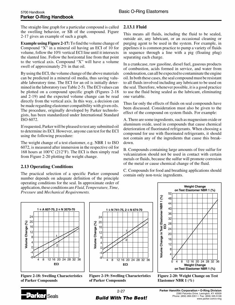
Parker O-Ring Handbook5700 Handbook Basic O-Ring Elastomers
2-27
Build With The Best!SealsParker Hannifin Corporation • O-Ring Division
2360 Palumbo Drive, Lexington, KY 40509Phone: (859) 269-2351 • Fax: (859) 335-5128
www.parker.com/o-ring
Figure 2-18: Swelling Characteristicsof Parker Compounds
Figure 2-20: Weight Change on TestElastomer NBR 1 (%)
4 8 12 16 20 24 28 32 36
ECI
Volu
me
Cha
nge
(%)
-8
-4
0
4
8
12 1
2
16
20
24
1 = N 741-75, 2 = N 674-70^ ^
Figure 2-19: Swelling Characteristicsof Parker Compounds
4 8 12 16 20 24 28 32 36
ECI
Volu
me
Cha
nge
(%)
-8
-4
0
4
8
121
2
16
20
24
1 = A 607-70, 2 = N 3570-70^ ^
Weight Changeon Test Elastomer NBR 1 (%)
0 4 8 12 16 20 24 28 32 36Weight Change
on Test Elastomer NBR 1 (%)
Volu
me
Cha
nge
inTe
st E
last
omer
NB
R 1
(%)
EC
I
4
8
12
16
20
24
28
32
36
40
44
48
52
2.13.1 Fluid
This means all fluids, including the fluid to be sealed,outside air, any lubricant, or an occasional cleaning orpurging agent to be used in the system. For example, inpipelines it is common practice to pump a variety of fluidsin sequence through a line with a pig (floating plug)separating each charge.
In a crankcase, raw gasoline, diesel fuel, gaseous productsof combustion, acids formed in service, and water fromcondensation, can all be expected to contaminate the engineoil. In both these cases, the seal compound must be resistantto all fluids involved including any lubricant to be used onthe seal. Therefore, whenever possible, it is a good practiceto use the fluid being sealed as the lubricant, eliminatingone variable.
Thus far only the effects of fluids on seal compounds havebeen discussed. Consideration must also be given to theeffect of the compound on system fluids. For example:
A. There are some ingredients, such as magnesium oxide oraluminum oxide, used in compounds that cause chemicaldeterioration of fluorinated refrigerants. When choosing acompound for use with fluorinated refrigerants, it shouldnot contain any of the ingredients that cause this break-down.
B. Compounds containing large amounts of free sulfur forvulcanization should not be used in contact with certainmetals or fluids, because the sulfur will promote corrosionof the metal or cause chemical change of the fluid.
C. Compounds for food and breathing applications shouldcontain only non-toxic ingredients.
The straight-line graph for a particular compound is calledthe swelling behavior, or SB of the compound. Figure2-17 gives an example of such a graph.
Example using Figure 2-17: To find the volume change ofCompound “X” in a mineral oil having an ECI of 10 forvolume, follow the 10% vertical ECI line until it intersectsthe slanted line. Follow the horizontal line from that pointto the vertical axis. Compound “X” will have a volumeswell of approximately 2% in that oil.
By using the ECI, the volume change of the above materialscan be predicted in a mineral oil media, thus saving valu-able laboratory time. The ECI for an oil is initially deter-mined in the laboratory (see Table 2-5). The ECI values canbe plotted on a compound specific graph (Figures 2-18and 2-19) and the expected volume change can be readdirectly from the vertical axis. In this way, a decision canbe made regarding elastomer compatibility with given oils.The procedure, originally developed by Parker technolo-gists, has been standardized under International StandardISO 6072.
If requested, Parker will be pleased to test any submitted oilto determine its ECI. However, anyone can test for the ECIusing the following procedure:
The weight change of a test elastomer, e.g. NBR 1 to ISO6072, is measured after immersion in the respective oil for168 hours at 100°C (212°F). The ECI is then simply readfrom Figure 2-20 plotting the weight change.
2.13 Operating Conditions
The practical selection of a specific Parker compoundnumber depends on adequate definition of the principleoperating conditions for the seal. In approximate order ofapplication, these conditions are Fluid, Temperature, Time,Pressure and Mechanical Requirements.

Parker O-Ring Handbook5700 Handbook Basic O-Ring Elastomers
2-28
Build With The Best!SealsParker Hannifin Corporation • O-Ring Division
2360 Palumbo Drive, Lexington, KY 40509Phone: (859) 269-2351 • Fax: (859) 335-5128
www.parker.com/o-ring
Figure 2-21: Temperature Capabilities of Principal Elastomers Employed in Seals
-100-148
-75-103
-50-58
-25-13
032
2577
50122
75167
100212
Temperature °C
125257
150302
175347
200392
225437
250482
300572
Normal recommended temperature range Extended temperature range for short term only.
Styrene-Butadiene Rubber (SBR)
Polyurethane Rubber (AU, EU)
Butyl Rubber (IIR)
Low Temperature Nitrile Rubber (NBR)
High Temperature Nitrile Rubber (NBR)
Hydrogenated Nitrile Rubber (HNBR)
Chloroprene Rubber (CR)
Polyacrylate Rubber (ACM)
Ethylene-Propylene-Diene-Rubber (EPDM)
Fluorosilicone-Rubber (FMQ, FVMQ)
TFE/Propropylene Rubber (FEPM)
Fluorocarbon Rubber (FKM)
Perfluorinated Elastomer (FFKM)
Silicone-Rubber (VMQ)
Temperature Range for Common Elastomeric Materials
°C°F
D. Seals used in meters or other devices that must be readthrough glass, a liquid, or plastic, must not discolor thesematerials and hinder vision.
Sound judgment, then, dictates that all fluids involved in anapplication be considered. Once this is done, it is a simplematter to check the Fluid Compatibility Tables in SectionVII to find a compound suitable for use with all the media.
2.13.2 Temperature
Temperature ranges are often over-specified. For example,a torch or burner might reach temperatures of 400°C to540°C (750°F to 1000°F). However, the tanks of gas beingsealed may be located a good distance from this heat sourceand the actual ambient temperature at the seal might be aslow as 121°C to 149°C (250°F to 300°F).
A specification for aircraft landing gear bearing seals mightcall out -54°C to 760°C (-65°F to 1400°F), yet the bearinggrease to be sealed becomes so viscous at -54°C (-65°F) itcannot possibly leak out. At the high end, there is a time-temperature relationship in the landing rollout that allowsrapid heat dissipation through the magnesium wheel hous-
ing on which the seals are mounted. This, combined withlow thermal conductivity of the seal, limits heat input to theseal so that temperature may never exceed 71°C (160°F).As a result, a more realistic temperature range would be-34°C to 82°C (-30°F to 180°F). This can be handled by agood, industrial type nitrile compound as N0674-70.
Parker has applied a realistic temperature range with amargin of safety when setting the general operating tem-perature range for seal compounds. The maximum tem-perature recommendation for a compound is based on longterm functional service. If it is subjected to this temperaturecontinuously, it should perform reliably for 1,000 hours.Time at less than maximum temperature will extend life.Similarly, higher temperature will reduce it.
The high temperature limits assigned to compounds inFigure 2-21 are conservative estimates of the maximumtemperature for 1,000 hours of continuous service in themedia the compounds are most often used to seal. Since thetop limit for any compound varies with the medium, thehigh temperature limit for many compounds is shown as arange rather than a single figure. This range may be reducedor extended in unusual fluids.
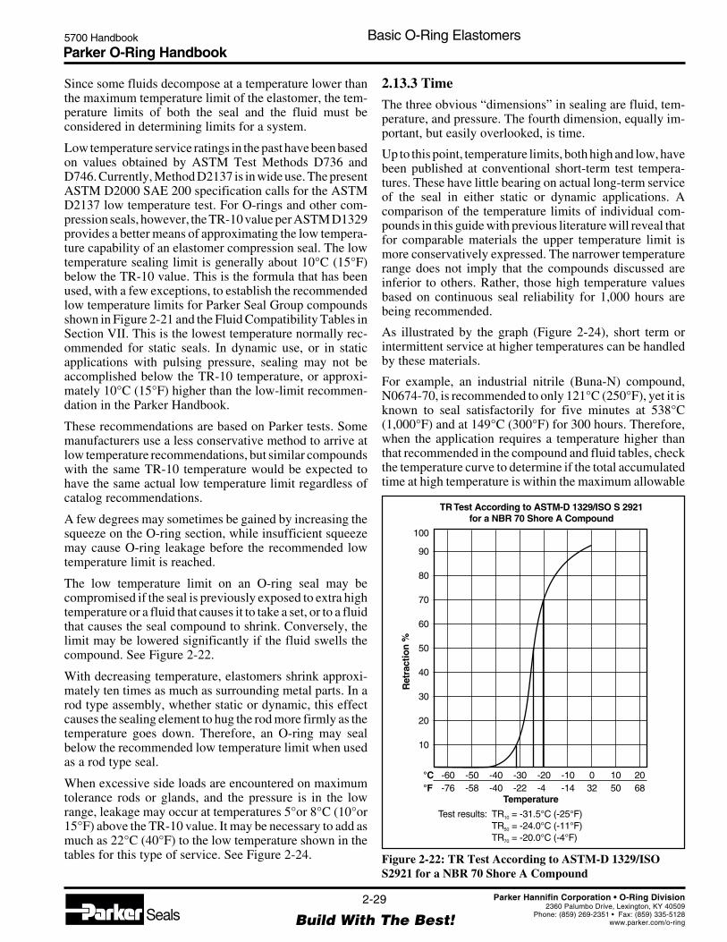
Parker O-Ring Handbook5700 Handbook Basic O-Ring Elastomers
2-29
Build With The Best!SealsParker Hannifin Corporation • O-Ring Division
2360 Palumbo Drive, Lexington, KY 40509Phone: (859) 269-2351 • Fax: (859) 335-5128
www.parker.com/o-ring
Since some fluids decompose at a temperature lower thanthe maximum temperature limit of the elastomer, the tem-perature limits of both the seal and the fluid must beconsidered in determining limits for a system.
Low temperature service ratings in the past have been basedon values obtained by ASTM Test Methods D736 andD746. Currently, Method D2137 is in wide use. The presentASTM D2000 SAE 200 specification calls for the ASTMD2137 low temperature test. For O-rings and other com-pression seals, however, the TR-10 value per ASTM D1329provides a better means of approximating the low tempera-ture capability of an elastomer compression seal. The lowtemperature sealing limit is generally about 10°C (15°F)below the TR-10 value. This is the formula that has beenused, with a few exceptions, to establish the recommendedlow temperature limits for Parker Seal Group compoundsshown in Figure 2-21 and the Fluid Compatibility Tables inSection VII. This is the lowest temperature normally rec-ommended for static seals. In dynamic use, or in staticapplications with pulsing pressure, sealing may not beaccomplished below the TR-10 temperature, or approxi-mately 10°C (15°F) higher than the low-limit recommen-dation in the Parker Handbook.
These recommendations are based on Parker tests. Somemanufacturers use a less conservative method to arrive atlow temperature recommendations, but similar compoundswith the same TR-10 temperature would be expected tohave the same actual low temperature limit regardless ofcatalog recommendations.
A few degrees may sometimes be gained by increasing thesqueeze on the O-ring section, while insufficient squeezemay cause O-ring leakage before the recommended lowtemperature limit is reached.
The low temperature limit on an O-ring seal may becompromised if the seal is previously exposed to extra hightemperature or a fluid that causes it to take a set, or to a fluidthat causes the seal compound to shrink. Conversely, thelimit may be lowered significantly if the fluid swells thecompound. See Figure 2-22.
With decreasing temperature, elastomers shrink approxi-mately ten times as much as surrounding metal parts. In arod type assembly, whether static or dynamic, this effectcauses the sealing element to hug the rod more firmly as thetemperature goes down. Therefore, an O-ring may sealbelow the recommended low temperature limit when usedas a rod type seal.
When excessive side loads are encountered on maximumtolerance rods or glands, and the pressure is in the lowrange, leakage may occur at temperatures 5°or 8°C (10°or15°F) above the TR-10 value. It may be necessary to add asmuch as 22°C (40°F) to the low temperature shown in thetables for this type of service. See Figure 2-24. Figure 2-22: TR Test According to ASTM-D 1329/ISO
S2921 for a NBR 70 Shore A Compound
100
90
80
70
60
50
40
20
10
-60-76
-50-58
-40-40
-30-22
-20-4
-10-14
032
1050
2068
30
Ret
ract
ion
%
Temperature
°C°F
Test results: TR = -31.5°C (-25°F)TR = -24.0°C (-11°F)TR = -20.0°C (-4°F)
10
50
70
TR Test According to ASTM-D 1329/ISO S 2921for a NBR 70 Shore A Compound
2.13.3 Time
The three obvious “dimensions” in sealing are fluid, tem-perature, and pressure. The fourth dimension, equally im-portant, but easily overlooked, is time.
Up to this point, temperature limits, both high and low, havebeen published at conventional short-term test tempera-tures. These have little bearing on actual long-term serviceof the seal in either static or dynamic applications. Acomparison of the temperature limits of individual com-pounds in this guide with previous literature will reveal thatfor comparable materials the upper temperature limit ismore conservatively expressed. The narrower temperaturerange does not imply that the compounds discussed areinferior to others. Rather, those high temperature valuesbased on continuous seal reliability for 1,000 hours arebeing recommended.
As illustrated by the graph (Figure 2-24), short term orintermittent service at higher temperatures can be handledby these materials.
For example, an industrial nitrile (Buna-N) compound,N0674-70, is recommended to only 121°C (250°F), yet it isknown to seal satisfactorily for five minutes at 538°C(1,000°F) and at 149°C (300°F) for 300 hours. Therefore,when the application requires a temperature higher thanthat recommended in the compound and fluid tables, checkthe temperature curve to determine if the total accumulatedtime at high temperature is within the maximum allowable
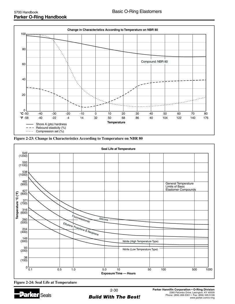
Parker O-Ring Handbook5700 Handbook Basic O-Ring Elastomers
2-30
Build With The Best!SealsParker Hannifin Corporation • O-Ring Division
2360 Palumbo Drive, Lexington, KY 40509Phone: (859) 269-2351 • Fax: (859) 335-5128
www.parker.com/o-ring
Figure 2-23: Change in Characteristics According to Temperature on NBR 80
Change in Characteristics According to Temperature on NBR 80100
80
60
40
20
0-50-58
-40-40
-30-22
-20-4
-1014
032
1050
2068
3086
4040
50104
60122
70140
80176
Compound: NBR 80
Temperature
°C°F
Shore A (pts) hardnessRebound elasticity (%)Compression set (%)
Figure 2-24: Seal Life at Temperature
Seal Life at Temperature
General TemperatureLimits of BasicElastomer Compounds
Exposure Time — Hours
Tem
pera
ture
°C
(°F)
0.1
649(1200)
593(1100)
538(1000)
482(900)
427(800)
371(700)
316(600)
260(500)
204(400)
149(300)
93(200)
38(100)
00.5 1.0 5.0 10 50 100 500 1000
Nitrile (Low Temperature Type)
Nitrile (High Temperature Type)
Ethylene Propylene & Neoprene
FluoroelastomerSilicone

Parker O-Ring Handbook5700 Handbook Basic O-Ring Elastomers
2-31
Build With The Best!SealsParker Hannifin Corporation • O-Ring Division
2360 Palumbo Drive, Lexington, KY 40509Phone: (859) 269-2351 • Fax: (859) 335-5128
www.parker.com/o-ring
limit. The sealing ability of a compound deteriorates withtotal accumulated time at temperature. The curves show thesafe, cumulative time at a given temperature for specificelastomers used as static seals. For dynamic seal applica-tions, temperatures as much as 14°C (25°F) below thoseindicated may be more realistic.
2.13.4 Pressure
The system operating pressure is always a consideration asit effects the choice of seal materials in several ways. Firstis hardness, as may be required to resist extrusion indynamic designs or where there is a large gap betweensealed members in static applications. Second is at-rest vsoperating conditions and requirements for “leakless” at restconditions which would suggest due consideration be givento the long-term compression set properties of a given material.
2.13.5 Mechanical Requirements
An important consideration in selecting the proper sealmaterial should be the nature of its mechanical operation,i.e. reciprocating, oscillating, rotating, or static. How theseal functions will influence the limitations on each of theparameters (fluids, temperature, pressure, and time) previ-ously discussed.
Static applications require little additional compound con-sideration. The prime requisite of a static seal compound isgood compression set resistance.
Dynamic applications, due to movement, are more in-volved. All properties must approach the optimum in adynamic seal compound, resilience to assure that the sealwill remain in contact with the sealing surface, low tem-perature flexibility to compensate for thermal contractionof the seal, extrusion resistance to compensate for widergaps which are encountered in dynamic glands, and abra-sion resistance to hold to a minimum the wearing away oreroding of the seal due to rubbing.
2.14 Selecting a Compound
Having discussed the major aspects of seal design thataffect compound selection, here is a summary of the neces-sary steps to follow, always keeping in mind that standardcompounds should be used wherever possible for availabil-ity and minimum cost.
1. If military fluid or rubber specifications apply, select thecompound from Table 8-2 or 8-3 in Section VIII, Specifi-cations.
2. For all other applications, locate all fluids that will comein contact with the seal in the Fluid Compatibility Tables inSection VII.
3. Select a compound suitable for service in all fluids,considering the mechanical (pressure, dynamic, static) andtemperature-time requirements of the application.
4. If a compound of different durometer from that listed inthe Fluid Compatibility Tables in Section VII must be used,contact the O-Ring Division for a harder or softer com-pound in the same base polymer.
2.15 Compound Similarity
General purpose O-ring compounds are listed by polymerand Shore A durometer hardness for ease of selection. Notethat the last two digits of Parker O-Ring compound num-bers indicate this type A hardness. For example, compoundE0540-80 is an 80-durometer material. The one exceptionis compound 47-071, which is a 70-durometer compound.
Butadiene, chlorosulfonated polyethylene, isoprene, natu-ral rubber, and a few other elastomers do not generallyperform as well as the listed polymers in seal applications,and Parker does not normally offer O-rings in these materials.
See Table 2-2 for comparison of similar properties bypolymer family.
2.16 Testing
An elastomer is seldom under the same confinement con-ditions when laboratory physical property tests are made aswhen installed as a seal. The usual compression, lack oftension, and limited room for expansion when installed, allresult in a different physical response from what is mea-sured on an identical but unconfined part.
Example: A silicone compound tested in hydrocarbon fuelin the free state may exhibit 150% swell. Yet seals of sucha compound confined in a gland having volume only 10%larger than the seal, may well perform satisfactorily. Com-plete immersion may be much more severe than an actualapplication where fluid contact with the seal is limitedthrough design. The service could involve only occasionalsplash or fume contact with the fluid being sealed. Differentparts made from the same batch of compound under iden-tical conditions will give varying results when tested inexactly the same way because of their difference in shape,thickness, and surface to volume relationship (see Figure 2-25). Humidity alone has been found to affect the tensilestrength of some compounds.
Correlation between test data and service conditions is nota simple problem; it is an industry-wide problem. Untilimprovement can be made, manufacturers and users mustuse the available data to the best of their ability. In essence,it is the misapplication of data, not the measurements,which causes difficulty. However, with data in some otherform, such misapplication might be greatly reduced. ASTMDesignation D471 (Standard Method of Test for Change inProperties of Elastomeric Vulcanizates Resulting fromImmersion in Liquids) states: “In view of the wide varia-tions often present in service conditions, this acceleratedtest may not give any direct correlation with service perfor-

Parker O-Ring Handbook5700 Handbook Basic O-Ring Elastomers
2-32
Build With The Best!SealsParker Hannifin Corporation • O-Ring Division
2360 Palumbo Drive, Lexington, KY 40509Phone: (859) 269-2351 • Fax: (859) 335-5128
www.parker.com/o-ring
mance. However, the method yields comparative data onwhich to base judgment as to expected service quality andis especially useful in research and development work.”
2.17 Specifications
Specifications are important, but so is progress. Therefore,even though it may be more difficult to prepare, a perfor-mance specification is recommended. This allows newdevelopments and improvements to be adopted without anyappreciable effect on the specification.
Avoid specifying how to compound materials or processcompounds. Let the seal manufacturer examine the perfor-mance desired. A vendor should be allowed to supply hisbest solution to a problem. It is not only possible, but alsoprobable that a well-qualified supplier knows of materialsand/or processes that will solve the problem and one shouldbe permitted to use them.
It must be recognized that physical properties provide ameans of screening new materials for an application bysetting realistic minimums. These can be established whenexperience with certain properties gives a good indicationof the suitability of a new material for the application.These properties also permit control of a material after ithas proven satisfactory for an application. Therefore, abrief discussion of the main points that should be consid-ered when preparing the physical and chemical test por-
Figure 2-25: Relative Effect of O-ring Cross Section onArea Exposed to Fluid Attack (Total Immersion)
Relative Effect of O-Ring Cross Section on AreaExposed to Fluid Attack (Total Immersion)
Cross Section (W)Inchmm
Rat
io —
Sur
face
to M
ass
00
0
60
50
40
30
20
10
1.3.05
2.5.10
3.8.15
5.1.20
6.4.25
7.6.30
tions of a specification follows. The discussion is in theorder that specifications are usually written and tests car-ried out. There are three major points that must always beconsidered when preparing any specification. These are:
1. Different size parts give different results (see Figure2-26). All parts with varying cross section or shape will notmeet specific properties set up on another particular part oron test specimens cut from a standard 6"x6"x0.075 inch testsheet. Therefore, always designate the actual parts onwhich the tests are to be conducted for both qualificationand control. For example, call for a particular size O-ring —not just an O-ring — if the standard ASTM 6"x6"x0.075test platens are not to be used.
2. Always use standard hardness discs (1.28" dia. = 1 in² by1/4" thick) or 6x6x0.75 sheets plied up to a minimumthickness of 1/4" to determine durometer hardness. It hasbeen almost impossible to obtain reliable and reproduciblehardness readings on seals with curved surfaces and vari-able cross sections (such as O-rings). This problem hasplagued the industry for years and is acknowledged in bothspecification and test standards. For example:
ASTM Method D2240, paragraph 6-1 states: “Asuitable hardness determination cannot be made on arounded, uneven, or rough surface.”
3. It is recommended that standard test methods be usedwhenever possible. Consider the case of the deviation fromthe standard methods of taking instantaneous durometerreadings. Occasionally, fifteen or thirty second delayeddurometer readings are specified. A delayed durometerreading results in a lower durometer value than would beobtained with the standard instantaneous reading. Thisusually causes widespread confusion and enlarges theproblem of correlation.
Where feasible, designate a standard test method for eachtest required by a specification (either ASTM or ISO TestMethod). These methods are widely used and help to assurecorrelation among laboratories. Correlation of results isperhaps the hardest thing to assure when preparing aspecification. However, adhering to the procedures de-scribed above minimizes this problem.
Every well-written specification should contain both quali-fication and control sections. Although these two sectionsmay be combined in the actual specification, they arediscussed separately.
2.18 Qualification Testing
Functional requirements should always be given first. Onefunctional test is worth more than a thousand physical andchemical property tests. The following discussion will leadto a specification for qualification of new seal compoundsafter the known functional requirements appear to correlatewith field or laboratory, chemical or physical results. Thus

Parker O-Ring Handbook5700 Handbook Basic O-Ring Elastomers
2-33
Build With The Best!SealsParker Hannifin Corporation • O-Ring Division
2360 Palumbo Drive, Lexington, KY 40509Phone: (859) 269-2351 • Fax: (859) 335-5128
www.parker.com/o-ring
the first step is to set the original physical property limitsthat will assure that the mechanical properties desired in theseal are present. These are in addition to the functional tests.
2.18.1 Original Physical Properties
Original Physical Properties (before exposure to serviceconditions) are those measurable attributes of an elastomerformulation which define certain physical parameters usedin determining the suitability of a given elastomer materialfor a given class of service. Certain of these properties arealso used in quality assurance testing to maintain batchcontrol and assure consistency between individual manu-facturing lots of compound. Original Physical Propertiesare also used in limiting/delimiting rubber specifications.These properties are:
a. Durometer
Durometer or Hardness is measured in points with a ShoreA instrument. Determine the durometer best suited for theapplication and round off (50, 65, 70, 85). A standard ±5point tolerance is established to allow the vendor a realisticworking range and permit normal variations experienced inreading durometer.
b. Tensile Strength
Determine the minimum tensile strength necessary for theapplication. Always take into consideration the inherentstrength of the elastomers most likely to be used to meet thespecification (most silicones have tensile strengths in the
range of 34.5 to 62.1 Bar (500 to 900 PSI); therefore, itwould be foolhardy to specify a minimum tensile strengthrequirement of 138 Bar (2,000 PSI) for a silicone material).
Once the minimum tensile strength has been set, multiplyit by 1.20 (for example: 69 Bar x 1.20 = 82.8 Bar (1,000 PSIx 1.20 = 1200 PSI)). This is the minimum limit set fortensile strength in the qualification section. It provides forthe normal tensile strength variation of ±15% experiencedbetween production batches of a compound.
c. Elongation
Investigate and determine the maximum amount of stretcha seal must undergo for assembly in the application. Mul-tiply this figure by 1.25 to allow a safety factor and toprovide for normal production variation of ±20%.
d. Modulus
Choose a minimum modulus that will assure a good state ofcure, good extrusion resistance, and good recovery frompeak loads. Keep in mind the original tensile and elongationfigures established in (b.) and (c.). Modulus is directlyrelated to these two properties.
e. Specific Gravity
A value for specific gravity should not be set in thequalification section of the specification but the valueshould be reported “as determined.” This value will then beused in the control section.
Figure 2-26: Variance in O-ring Volume Change With Cross-Section W*Averages of many samples
Variance in O-Ring Volume Change With Cross-Section W
Immersion Time at 70°C (158°F) — Weeks
0
6
10
8
6
4
2
01 2 3 4 5 6
4
2
0
-20.070*
0.103*
0.139*
0.210
0.139
0.1030.2100.0700.060
0.275
W
W
1 2 3
Volu
me
Cha
nge
— P
erce
nt
Volu
me
Cha
nge
— P
erce
nt
MIL P-5516 NitrileImmersed inMIL-H-5606 (J-43)
Butyl RubberImmersed inSkydrol 500A
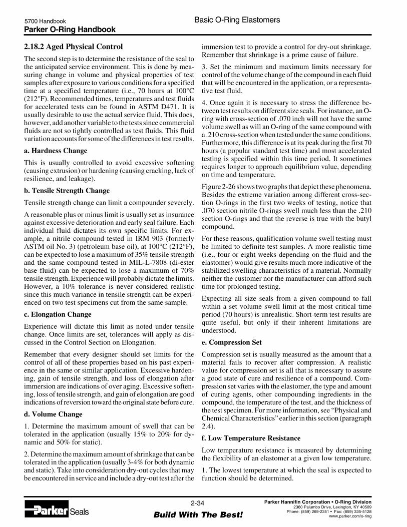
Parker O-Ring Handbook5700 Handbook Basic O-Ring Elastomers
2-34
Build With The Best!SealsParker Hannifin Corporation • O-Ring Division
2360 Palumbo Drive, Lexington, KY 40509Phone: (859) 269-2351 • Fax: (859) 335-5128
www.parker.com/o-ring
2.18.2 Aged Physical Control
The second step is to determine the resistance of the seal tothe anticipated service environment. This is done by mea-suring change in volume and physical properties of testsamples after exposure to various conditions for a specifiedtime at a specified temperature (i.e., 70 hours at 100°C(212°F). Recommended times, temperatures and test fluidsfor accelerated tests can be found in ASTM D471. It isusually desirable to use the actual service fluid. This does,however, add another variable to the tests since commercialfluids are not so tightly controlled as test fluids. This fluidvariation accounts for some of the differences in test results.
a. Hardness Change
This is usually controlled to avoid excessive softening(causing extrusion) or hardening (causing cracking, lack ofresilience, and leakage).
b. Tensile Strength Change
Tensile strength change can limit a compounder severely.
A reasonable plus or minus limit is usually set as insuranceagainst excessive deterioration and early seal failure. Eachindividual fluid dictates its own specific limits. For ex-ample, a nitrile compound tested in IRM 903 (formerlyASTM oil No. 3) (petroleum base oil), at 100°C (212°F),can be expected to lose a maximum of 35% tensile strengthand the same compound tested in MIL-L-7808 (di-esterbase fluid) can be expected to lose a maximum of 70%tensile strength. Experience will probably dictate the limits.However, a 10% tolerance is never considered realisticsince this much variance in tensile strength can be experi-enced on two test specimens cut from the same sample.
c. Elongation Change
Experience will dictate this limit as noted under tensilechange. Once limits are set, tolerances will apply as dis-cussed in the Control Section on Elongation.
Remember that every designer should set limits for thecontrol of all of these properties based on his past experi-ence in the same or similar application. Excessive harden-ing, gain of tensile strength, and loss of elongation afterimmersion are indications of over aging. Excessive soften-ing, loss of tensile strength, and gain of elongation are goodindications of reversion toward the original state before cure.
d. Volume Change
1. Determine the maximum amount of swell that can betolerated in the application (usually 15% to 20% for dy-namic and 50% for static).
2. Determine the maximum amount of shrinkage that can betolerated in the application (usually 3-4% for both dynamicand static). Take into consideration dry-out cycles that maybe encountered in service and include a dry-out test after the
immersion test to provide a control for dry-out shrinkage.Remember that shrinkage is a prime cause of failure.
3. Set the minimum and maximum limits necessary forcontrol of the volume change of the compound in each fluidthat will be encountered in the application, or a representa-tive test fluid.
4. Once again it is necessary to stress the difference be-tween test results on different size seals. For instance, an O-ring with cross-section of .070 inch will not have the samevolume swell as will an O-ring of the same compound witha .210 cross-section when tested under the same conditions.Furthermore, this difference is at its peak during the first 70hours (a popular standard test time) and most acceleratedtesting is specified within this time period. It sometimesrequires longer to approach equilibrium value, dependingon time and temperature.
Figure 2-26 shows two graphs that depict these phenomena.Besides the extreme variation among different cross-sec-tion O-rings in the first two weeks of testing, notice that.070 section nitrile O-rings swell much less than the .210section O-rings and that the reverse is true with the butylcompound.
For these reasons, qualification volume swell testing mustbe limited to definite test samples. A more realistic time(i.e., four or eight weeks depending on the fluid and theelastomer) would give results much more indicative of thestabilized swelling characteristics of a material. Normallyneither the customer nor the manufacturer can afford suchtime for prolonged testing.
Expecting all size seals from a given compound to fallwithin a set volume swell limit at the most critical timeperiod (70 hours) is unrealistic. Short-term test results arequite useful, but only if their inherent limitations areunderstood.
e. Compression Set
Compression set is usually measured as the amount that amaterial fails to recover after compression. A realisticvalue for compression set is all that is necessary to assurea good state of cure and resilience of a compound. Com-pression set varies with the elastomer, the type and amountof curing agents, other compounding ingredients in thecompound, the temperature of the test, and the thickness ofthe test specimen. For more information, see “Physical andChemical Characteristics” earlier in this section (paragraph2.4).
f. Low Temperature Resistance
Low temperature resistance is measured by determiningthe flexibility of an elastomer at a given low temperature.
1. The lowest temperature at which the seal is expected tofunction should be determined.

Parker O-Ring Handbook5700 Handbook Basic O-Ring Elastomers
2-35
Build With The Best!SealsParker Hannifin Corporation • O-Ring Division
2360 Palumbo Drive, Lexington, KY 40509Phone: (859) 269-2351 • Fax: (859) 335-5128
www.parker.com/o-ring
2. The low temperature test method that most nearly simu-lates the actual service requirement should be chosen togive the best possible assurance that the seal which passesthis test will function in the application. Parker believes thatthe Temperature Retraction Test (TR-10) is the best methodfor determining a compound’s ability to seal at low tem-peratures. Most low temperature tests are designed toindicate the brittle point of a material. This only tells at whatlow temperature the compound is most likely to be com-pletely useless as a seal in a standard design, but very littleabout the temperature at which it is useful. This is not thecase with TR-10 that consists of stretching 3 or 4 samples50%, freezing them, then warming them gradually at aconstant rate, and finally recording the temperature atwhich the samples have returned to 9/10 of the originalstretch (1/10 return). This temperature (TR-10) then is thelowest temperature at which the compound exhibits rub-ber-like properties and therefore relates to low temperaturesealing capabilities. Functional tests indicate that O-ringswill usually provide reliable dynamic sealing at or belowthe TR-10 value. Static O-rings normally function satisfac-torily to about -9°C (15°F) below this.
2.19 Process Control
The purpose of process control is to insure uniformity ofpurchased parts from lot to lot. Process control may bebased on the requirements of the qualification section oractual qualification test results. Both of these methods haveinherent weaknesses. When a material is qualified to aspecification close to the specification limits, normal pro-duction variation may cause the material to fall outside thelimits. This could result in unnecessary rejection of goodparts. Therefore it is suggested that control be based onactual test results of the material in question.
One should be careful not to be trapped by writing aspecification based on one test report having only a singleset of values. Any single set of tests made on a particularbatch, or laboratory samples, is very unlikely to reflectmean values that can be duplicated day-in and day-out inproduction. Seal manufacturers have accumulated years oftest experience on popular, successful compounds. Thisinformation is available from Parker on request. WithParker’s CBI program it is practical to refer to the batchfrom which any seal was made, as well as compoundstatistical capability and history.
Many of the typical tests for determining a compound’sphysical and chemical properties that are specified in thequalification section are unnecessary to provide good con-trol of an approved material. Discussion will be limited toonly those properties really pertinent to the control sectionof the specifications.
a. Hardness is often specified as a control. It is frequentlyproblematic because of inherent difficulties in measuring
durometer with seal specimens rather than standard hard-ness discs, or platen plies.
A tolerance of ±5 points is the standard allowance forexper-imental error caused by reading techniques and pro-duction variance from batch to batch of the same com-pound. This tolerance is sometimes applied to the actualqualification results. For example, — if the qualificationsection specified 70-durometer ±5 and the qualificationvalue was a 68-durometer reading, the control sectionwould specify 68 ± 5. This is the most desirable approach.In some cases original qualification hardness and toleranceremain in effect (i.e., both qualification and control valuesof 70 ± 5). This practice is more likely to result in unneces-sary rejection of usable parts. Needless expense and muchhigher prices may result.
b. Tensile Strength, a tolerance of ±15% is standard forany given compound. This tolerance was taken into consid-eration when establishing the tensile strength qualificationlimit of 1200 psi for dynamic seals (see qualificationsection, tensile strength). If a part qualified at the minimum,82.8 Bar (1200 PSI), and the control tolerance is applied, itis possible to receive a part with a tensile strength of 70.4Bar (1020 PSI). This value, 70.4 Bar (1020 PSI), remainsabove the (69 Bar (1,000 PSI) minimum that is usuallyrequired for dynamic applications as previously stated.
c. Elongation, a tolerance of ±20% is standard. Again thismust be taken into consideration as part of the safety factor,when setting a limit for elongation for qualification.
d. Modulus, a tolerance of ±20% is standard. This is a moresensitive indicator of the condition of a compound thaneither tensile strength or elongation.
e. Specific Gravity of a compound having been establishedduring qualification, a tolerance of ±.02 may be applied.Specific gravity is the easiest and quickest control testavailable to the industry today. It is also the most accurateif the stringent ±.02 tolerance is applied. Specific gravity isthe only test some purchasers use.
f. Volume Change, a plus or minus tolerance on thisproperty is frequently unrealistic. A combination of vari-ance in commercial fluids and sample size, gives such anaccumulation of negative factors that it is not alwaysfeasible to use volume swell as a control. It can be done if,(1) a controlled test fluid is used or control of the commer-cial fluid eliminates its variance, (2) time of the test isextended, (3) a volume swell history over a long period oftime is established on every seal on which a check isdesired, and (4) when testing small size seals multiplesamples are used for each weighing, thus minimizinginaccuracy (for example: if the balance being used isaccurate to .01 gram and a small seal with a weight of .03gram is being tested, it is easy to see where an answer on thissize seal can be extremely inaccurate).

Parker O-Ring Handbook5700 Handbook Basic O-Ring Elastomers
2-36
Build With The Best!SealsParker Hannifin Corporation • O-Ring Division
2360 Palumbo Drive, Lexington, KY 40509Phone: (859) 269-2351 • Fax: (859) 335-5128
www.parker.com/o-ring
If controls are established for the above properties and acompound complies, specifying additional tests is not nec-essary.
Guard against specifying unrealistically high physical prop-erties that may in reality be detrimental to a seal due to thegreater percentage drop-off of these properties after shortperiods of exposure to fluids (see Figure 2-27). In manyapplications, a compound in accordance with MIL-R-7362has outperformed MIL-P-25732 material at both high andlow temperature.
Remember, building in too much of a safety factor in thespecification can lead to costs that are prohibitive becausethe best looking laboratory reports are desired. If thecompounder is forced to develop a material that is ex-tremely difficult to process, manufacturing costs will in-
Figure 2-27: Physical Property Change from Immersion
Immersion Time in MIL-L-7808 at 100°C (212°F) — Hours
Tens
ile S
tren
gth
— B
ar (P
SI)
Physical Property Change From Immersion
CompoundPer MIL-P-25732
172.5(2500)
138.0(2000)
103.5(1500)
69.0(1000)
34.5(500)
00 24 48 72 96 120 144 168
Original
After Immersion
-57%
-5%CompoundPer MIL-R-7362 -10%
-46%
crease due to higher scrap rates. The customer ultimatelybears these costs.
Each seal supplier has developed numerous nitrile com-pounds to meet various specifications, all written to accom-plish the same thing — to obtain a seal suitable for use witha petroleum base hydraulic fluid. The result, many differentcompounds available for the same service, any one ofwhich would perform satisfactorily in almost all the appli-cations.
Only the more common physical and chemical propertytests have been discussed. When preparing a specificationand in need of assistance, please call on a Parker Sealrepresentative in your area. They will be more than happyto help you.

Parker O-Ring Handbook5700 Handbook O-Ring Applications
3-1
Build With The Best!SealsParker Hannifin Corporation • O-Ring Division
2360 Palumbo Drive, Lexington, KY 40509Phone: (859) 269-2351 • Fax: (859) 335-5128
www.parker.com/o-ring
Section IIIO-Ring Applications
3.0 Introduction ............................................................................................................................................. 3-3
3.1 Factors Applying to All O-Ring Types ............................................................................................. 3-3
3.1.1 Compatibility ............................................................................................................................ 3-3
3.1.2 Temperature .............................................................................................................................. 3-4
3.1.3 Pressure ..................................................................................................................................... 3-4
3.1.4 Extrusion ................................................................................................................................... 3-4
3.1.5 Lubrication ............................................................................................................................... 3-5
3.1.5.1 Parker O-Lube .................................................................................................................. 3-5
3.1.5.2 Parker Super O-Lube ....................................................................................................... 3-5
3.1.5.3 Other Friction Reduction Methods .................................................................................. 3-6
3.1.5.4 Internal Lubrication ......................................................................................................... 3-6
3.2 Cleanliness ........................................................................................................................................ 3-6
3.3 Assembly .......................................................................................................................................... 3-6
3.4 Selecting the Best Cross-Section ...................................................................................................... 3-7
3.5 Stretch ............................................................................................................................................... 3-8
3.6 Squeeze ............................................................................................................................................. 3-8
3.7 Gland Fill .......................................................................................................................................... 3-9
3.8 O-Ring Compression Force .............................................................................................................. 3-9
3.9 Specific Applications ........................................................................................................................ 3-9
3.9.1 Automotive ............................................................................................................................... 3-9
3.9.2 Engine ..................................................................................................................................... 3-10
3.9.3 Brake System .......................................................................................................................... 3-10
3.9.4 Fuel System ............................................................................................................................ 3-10
3.9.5 Fuels for Automobile Engines ................................................................................................ 3-10
3.9.6 Transmission ........................................................................................................................... 3-11
3.9.7 Cooling & Heating Systems ................................................................................................... 3-11
3.9.8 Air Conditioning ..................................................................................................................... 3-12
3.9.9 Power Steering Systems ......................................................................................................... 3-12
3.9.10 Refrigeration and Air Conditioning ...................................................................................... 3-12
3.9.11 Food, Beverage and Potable Water ....................................................................................... 3-12
3.9.12 Aerospace Technology .......................................................................................................... 3-13
3.9.12.1 Jet Fuels ....................................................................................................................... 3-13
3.9.12.2 Liquid Rocket Propellants ........................................................................................... 3-13
3.9.13 Nuclear Technology .............................................................................................................. 3-14
3.9.14 Radiation ............................................................................................................................... 3-14
3.9.15 Chemical Processing/Oil Field Technology ......................................................................... 3-14

Parker O-Ring Handbook5700 Handbook O-Ring Applications
3-2
Build With The Best!SealsParker Hannifin Corporation • O-Ring Division
2360 Palumbo Drive, Lexington, KY 40509Phone: (859) 269-2351 • Fax: (859) 335-5128
www.parker.com/o-ring
3.9.16 Fungus-Resistant Compounds .............................................................................................. 3-15
3.9.17 Hydraulic Fluids ................................................................................................................... 3-16
3.9.17.1 Fire-Resistant Hydraulic Fluids ................................................................................... 3-16
3.9.17.1.1 HFA Fluids ........................................................................................................ 3-16
3.9.17.2 Concentrates Containing Mineral Oils (Oil-in-Water-Solutions) ................................ 3-16
3.9.17.3 Micro-Emulsions ......................................................................................................... 3-16
3.9.17.4 Synthetic HFA Concentrates (Solutions) ..................................................................... 3-16
3.9.17.5 HFC Fluids ................................................................................................................... 3-17
3.9.17.6 HFD Fluids .................................................................................................................. 3-18
3.10 Temperature Extremes .................................................................................................................. 3-18
3.10.1 High Temperature ................................................................................................................. 3-18
3.10.2 Low Temperature .................................................................................................................. 3-18
3.11 Vacuum Applications .................................................................................................................... 3-19
3.11.1 Vacuum Weight Loss ............................................................................................................ 3-19
3.11.2 Vacuum Seal Considerations ................................................................................................ 3-19
3.11.3 Vacuum Leak Rate ................................................................................................................ 3-21
3.12 Gases-Permeability ....................................................................................................................... 3-21
3.12.1 Leak Rate Approximation ..................................................................................................... 3-21
3.13 Gases-High Pressure ..................................................................................................................... 3-22
3.14 Acids ............................................................................................................................................. 3-22
3.14.1 Plastic Contact Surfaces ....................................................................................................... 3-22
3.14.2 Silicone Fluids ...................................................................................................................... 3-23
3.14.3 Underwriters' Laboratories ................................................................................................... 3-23
3.14.5 Water and Steam Resistance ................................................................................................. 3-23
3.15 Semiconductor .............................................................................................................................. 3-23
3.16 inPHorm Seal Design and Material Selection Software............................................................... 3-24
3.17 Drive Belts ................................................................................................................................. 3-25
3.17.1 Introduction .......................................................................................................................... 3-25
3.17.2 Drive Belt Compound Selection ........................................................................................... 3-25
3.17.3 Available Drive Belt Compounds ........................................................................................ 3-25
3.18 Applications Summary ................................................................................................................. 3-26

Parker O-Ring Handbook5700 Handbook O-Ring Applications
3-3
Build With The Best!SealsParker Hannifin Corporation • O-Ring Division
2360 Palumbo Drive, Lexington, KY 40509Phone: (859) 269-2351 • Fax: (859) 335-5128
www.parker.com/o-ring
3.0 Introduction
In designing an O-ring seal, it is best to determine the O-ringcompound first, as the selected compound may have sig-nificant influence on gland design parameters.
Essentially, the application determines the rubber com-pound; the primary factor being the fluid to be sealed. Theelastomer however, must also resist extrusion when ex-posed to the maximum anticipated system pressure and becapable of maintaining good physical properties throughthe full temperature range expected. In dynamic applica-tions, the selected material must also have the toughnessand abrasion resistance so important in reciprocating androtary seals.
The Fluid Compatibility Tables in Section VII suggestpotential Parker Compounds for over two thousand differ-ent gases, fluids and solids. Normally, the “RecommendedParker O-Ring Compound” indicated in the tables shouldbe the one specified for initial testing and evaluation.
In some instances, where there are two or more fluids to besealed, it may be necessary to compromise on a sealmaterial having the best overall resistance to all the fluidsinvolved. Whenever possible this should be a compoundrated “1” for all the fluids under consideration. For a staticseal application, a “2” rating is usually acceptable, but itshould, in all cases, be tested. Where a “2” rated compoundmust be used, do not expect to re-use it after disassembly.It may have degraded enough that it cannot safely bereinstalled.
When a compound rated “3” is selected, be certain it is firstthoroughly tested under the full range of anticipated oper-ating conditions. Some of these 3-rated compounds mayprove to be satisfactory as static seals, but many will not.
Note the operating temperature range of the chosen com-pound. The temperatures shown in Table 7-1 are generaltemperature ranges, but the presence of a particular fluidmay modify the published limits. Remember, only appro-priate testing can safely determine an acceptable O-ringseal material.
If a compound designated “Static only” is the only com-pound recommended for the fluids, and the application isdynamic, the compound may nevertheless be suitable insome unique situations. Bear in mind that “Static only”compounds are not as tough and abrasion resistant as othermaterials, and would normally wear more rapidly in adynamic environment.
If the anticipated seal motion is infrequent, or if the seal canbe replaced often, a “Static only” compound will probablybe satisfactory.
If, for some reason a compound of different shore hardnessfrom the one suggested in the Fluid Compatibility Table isneeded, compounds of other hardnesses in the same poly-mer are available. Contact the O-Ring Division.
When two or more compounds are suitable for a givenapplication, price and stock availability may become deter-mining factors. Current piece-price and in-stock availabil-ity can be obtained from your nearest Authorized ParkerO-Ring Distributor.
Following this introduction are discussions on a number ofspecial applications that require additional attention. It isrecommended that the designer consult the applicationslisted and read carefully any of those paragraphs whichapply to his application.
3.1 Factors Applying to All O-Ring Types
For the majority of standard applications, the design of theO-ring seal has generally already been accomplished. Thenecessary data for gland dimensions are simply selectedfrom the tables in the sections on Static and DynamicO-Ring Sealing, Sections IV and V, respectively. The valueof making a detailed comparison between previouslysatisfactory installations and a new one cannot be over-emphasized. Such comparison should disclose any weakpoints where modification may be desireable or required,thus simplifying the process and facilitating the designeffort.
The following paragraphs discuss the more importantdesign factors that generally apply to all O-ring seals. Dataand procedures enabling the designer to depart from thestandard designs in order to meet peculiar requirements, orto obtain improved performance from the seal will also befound in this section.
Specific design and dimensional data applicable to staticseals is provided in the Static O-Ring Sealing Section (IV),and information on dynamic seals is contained in theDynamic O-Ring Sealing Section (V).
3.1.1 Compatibility
Compatibility between the O-ring and the fluid or fluids tobe sealed must be the first consideration in the designprocess. If the fluid will have an immediate adverse effect
APPLICATIONS

Parker O-Ring Handbook5700 Handbook O-Ring Applications
3-4
Build With The Best!SealsParker Hannifin Corporation • O-Ring Division
2360 Palumbo Drive, Lexington, KY 40509Phone: (859) 269-2351 • Fax: (859) 335-5128
www.parker.com/o-ring
(chemical reaction resulting in surface destruction, loss ofstrength, degradation, or other marked change in physicalproperties) resulting in shortened seal life, there is littleadvantage to be gained by proceeding further with thedesign until this basic problem is resolved.
If more than one fluid is involved, both the sequence ofexposure and time of contact with the O-ring need beconsidered. If compatibility cannot be determined fromspecific data in this section or the Fluid CompatibilityTables in Section VII, refer the problem to your ParkerField Engineer, Parker O-Ring Distributor or contact theInside Sales Engineering Department of the Parker O-RingDivision at (606) 269-2351.
3.1.2 Temperature
Operating temperature, or more properly, the range ofsystem temperature, may require some minor modificationof the gland design. Gland dimensions given in the staticand dynamic seal design sections are calculated for thetemperature ranges listed for standard compounds. If theoperation is only to be at a high temperature, gland volumemay need to be increased to compensate for thermal expan-sion of the O-ring. Conversely, for operation only at lowtemperature, a better seal may result by reducing the glanddepth, thereby obtaining the proper squeeze on the con-tracted O-ring. Table 2-4, which lists the approximate rateof linear thermal expansion for typical elastomers and othermaterials, may be utilized to calculate compensated glanddimensions. For either high or low temperature seal de-signs, however, there must normally be sufficient squeezeto prevent leakage at room temperature. Figure 3-1 illus-trates another possible type of design to improve lowtemperature sealing capability by spring loading the O-ring.
Such special designs for high and low temperature environ-ments are seldom required. The minimum squeeze valuesfor the various O-ring cross-section diameters given in thedesign charts of the static and dynamic seal design sectionsare generally satisfactory.
3.1.3 Pressure
Pressure has a bearing on O-ring seal design as it can affectthe choice of compound shore hardness. At very lowpressures, proper sealing may be more easily obtained withlower durometer hardness (50-60 shore A). With higherpressures, the combination of pressure and material shorehardness determine the maximum clearance that may safelybe tolerated (see Figure 3-2). Cyclic fluctuation of pressurecan cause local extrusion of the O-ring resulting in “nib-bling” (see Section VIII, Failure Analysis), particularly ifpeak system pressures are high enough to cause expansionof the cylinder wall. One remedy may be to stiffen thecylinder to limit the expansion so that the bore to pistonclearance does not exceed a safe value.
3.1.4 Extrusion
Extrusion of O-rings may also be prevented by the use ofanti-extrusion (back-up) devices. These are thin rings ofmuch harder material fitted into the gland between the sealand the clearance gaps, which essentially provide zeroclearance. They are available in hard elastomer compounds,leather, PTFE, Nylon and other similar materials. Parker
Figure 3-1: Spring-Loading for Low Temperature
GarterSpring
Soft Metal Wedge
O-Ring
Figure 3-2: Limits for extrusion
* Reduce the clearance shown by 60% when using silicone orfluorosilicone elastomers.
Basis for Curves1. 100,000 pressure cycles at the rate of 60 per minute from zero
to the indicated pressure.2. Maximum temperature (i.e. test temperature) 71°C (160°F).3. No back-up rings.4. Total diametral clearance must include cylinder expansion due
to pressure.5. Apply a reasonable safety factor in practical applications to
allow for excessively sharp edges and other imperfections andfor higher temperatures.
Total Diametral Clearance*(Radial Clearance if Concentricity Between Piston and
Cylinder is Rigidly Maintained)
In.mm
Flui
dP
ress
ure
(Bar
) FluidP
ressure(P
SI)
690.0 10,000552.0 8,000414.0 6,000
276.0 4,000
207.0 3,000
138.0 2,000
69.0 1,00055.2 800
41.4 600
27.6 400
20.7 300
13.8 200
6.9 10000
.3.010
.5.020
.8.030
1.0.040
Extrusion
70 80 90HardnessShore A
Limits for Extrusion
No Extrusion

Parker O-Ring Handbook5700 Handbook O-Ring Applications
3-5
Build With The Best!SealsParker Hannifin Corporation • O-Ring Division
2360 Palumbo Drive, Lexington, KY 40509Phone: (859) 269-2351 • Fax: (859) 335-5128
www.parker.com/o-ring
Parbaks® are elastomer back-up rings and are generallyrecommended based on their proven functional superiority.The exact point at which it becomes necessary to use anti-extrusion devices will depend on the pressure, type ofelastomer being used, its Shore hardness, the size of theclearance gap, and the degree of “breathing” of the metalparts which will be encountered. Figure 3-2 may be used asa guide in determining whether or not anti-extrusion ringsshould be used. When using the data, include in the diame-tral clearance any “breathing,” or expansion of the cylinderbore that may be anticipated due to pressure. Althoughbased on data obtained from O-rings, the ninety durometercurve can also be used as a guide to back-up ring perfor-mance. The Parbak Back-Up Rings Section (VI), describesin greater detail Parker Parbak back-up rings, and providessize and part number data. Also see “Patterns ofO-Ring Failure” in Section IX for more information onextrusion.
3.1.5 Lubrication
Lubrication of O-ring seals is extremely important forinstallation and operation of dynamic seals as well asproper seating of static seals. The general rule for use oflubrication is: The greatest benefit in using a lubricant isobtained during the initial installation of the O-ring.
Lubricants are commonly used on O-rings and other elas-tomeric seals. Using a suitable grease or oil during assem-bly helps protect the O-ring from damage by abrasion,pinching, or cutting. It also helps to seat the O-ring prop-erly, speeds up assembly operations, and makes automatedassembly line procedures possible. An additional benefit isthe protection that the lubricant provides as a surface film.Proper lubrication also helps protect some polymers fromdegradation by atmospheric elements such as ozone and its
presence helps extend the service life of any O-ring. Alubricant is almost essential in pneumatic applicationsrequiring dynamic service. In vacuum applications, appro-priate lubricants help reduce the overall leak rate by fillingthe microfine inclusions of the gland’s metal surfaces andlowering permeation rates of the elastomer.
Parker Seal offers two lubricants that will satisfy mostservice needs: Parker O-Lube and Parker Super-O-Lube.These two lubricants are described in the following para-graphs. Table 3-1 identifies their key properties.
3.1.5.1 Parker O-Lube is an outstanding general-pur-pose grease intended for use with O-ring and other seals inhydrocarbon service. It can also be used in pneumaticservice. The useful temperature is from -29°C to 82°C(-20°F to 180°F).
3.1.5.2 Parker Super-O-Lube is an all-purpose O-ringlubricant. It is not a grease, but rather a high-viscositysilicone oil. It is especially useful as a seal lubricant. Thetemperature range is -54°C to 204°C (-65°F to 400°F).
Parker Super-O-Lube can be used as an assembly lubricanton all rubber polymers, including silicones. (Note: Sili-cones require special consideration.) In addition, ParkerSuper-O-Lube has some unique advantages. It clings tena-ciously to rubber or metal surface helping to prevent it frombeing flushed away by action of the system fluid. It has oneof the widest temperature ranges of any seal lubricantavailable. It can be used for high pressure systems or inhard vacuum environments. Super-O-Lube’s inert naturelends itself to a wide variety of fluid systems. Since thereare no organic fillers, there can be no clogging of microfilters.
In addition to its outstanding performance in internal ser-vice, Parker Super-O-Lube gives protection to rubber poly-mers that are normally age sensitive when exposed to the
Parker O-Ring Lubricants
O-Lube Super-O-Lube
Type Petroleum Grease High viscosity silicone fluid
Temperature Range -29°C to 82°C(1) -54°C to 204°C(2)
(-20°F to 180°F) (-65°F to 400°F)
Seal Use Hydrocarbon fluids General PurposePneumatic systems under 200 PSI High pressure pneumatic
Suitable for Fluorocarbon FluorocarbonUse with Rubber Fluorosilicone FluorosiliconeCompounds: Neoprene Neoprene
Nitrile NitrilePolyacrylate PolyacrylatePolyurethane Polyurethane
ButylEthylene PropyleneSBR (GRS)Silicone(2)
Will Pass ThroughMicronic Filters? No Yes
Table 3-1: Parker O-Ring Lubricants
Notes: Assembly lubricants shouldalways be used sparingly duringapplication. A light film is all that isrequired. This is doubly important incases 1 and 2 below.
1. When only a thin film of O-Lube isused for assembly purposes, theassembly may be subjected tohigher temperatures, with limitsdetermined by the fluid andelastomer being used.
2. Use only a thin film of Super-O-Lubeon silicone rubber if the temperaturewill exceed 149°C (300°F).
Parbak® is a registered trademark of ParkerHannifin Corporation.

Parker O-Ring Handbook5700 Handbook O-Ring Applications
3-6
Build With The Best!SealsParker Hannifin Corporation • O-Ring Division
2360 Palumbo Drive, Lexington, KY 40509Phone: (859) 269-2351 • Fax: (859) 335-5128
www.parker.com/o-ring
atmosphere. This is a typical concern with ozone sensitivepolymers that require age control.
There are special situations that may exist where one of thetwo Parker lubricants would not be the best recommenda-tion. For instance, there may be a need for a special highvacuum grease, or a lubricant that would be especiallysuited to phosphate ester service. For guidance in handlingthese unique situations consult a Parker O-Ring DivisionInside Sales Engineer.
Before selecting a lubricant (other than the primary fluidbeing sealed) for use with O-rings, determine that it meetsthe following requirements:
1. It or any additives that it contains, should not causeshrinkage or excessive swelling of the O-ring compoundbeing used.
2. It should not excessively soften or solidify over theanticipated service temperature range.
3. It should not break-down and leave gummy or grittydeposits after cycling, or show any adverse chemical reac-tion with the primary fluid being sealed.
4. It should be capable of forming a thin, strong (highsurface tension) film over the metal being lubricated thatthe O-ring’s dynamic motion cannot wipe away.
5. It should pass through any filters used in the system.
3.1.5.3 Other Friction Reduction Methods
Besides O-Lube and Super-O-Lube, Parker Seal can supplyO-rings that have received various friction reducing treat-ments. These may include internal lubrication and Parker’sProprietary Lube Treatment. Both are valuable aids forautomated assembly operations, and may also be used inmany types of applications to reduce friction in service.
Note: While it is always preferable to use a lubricant,keep in mind that there are certain systems in whichlubricants would introduce unacceptable contamina-tion, such as semiconductor fabrication and processingequipment or medical and food processing devices.
3.1.5.4 Internal Lubrication
Internal lubrication involves the incorporation of frictionreducing ingredients into the elastomer formula. Since thisprocess alters the material’s chemistry, Parker’s internallylubricated materials are assigned unique compound numbersto differentiate them from their non-lubricated counterparts.
Internal lubricants consist of organic materials such asgraphite, molybdenum disulfide, powdered PTFE or, morecommonly, a proprietary Parker organic lubricant. Becausethe lubricant is dispersed throughout the body of an O-ring,this method of friction reduction generally functions longer
in service than external lubrication, but to a somewhatlesser degree.
Graphite-impregnated compounds are commonly used toseal rotary shafts. It should not however, be used in contactwith stainless steel surfaces because graphite tends to causecorrosive pitting of stainless materials. For such applica-tions, compounds containing molybdenum disulfide areoften a successful alternative.
Compound V0848-75 contains powdered PTFE to reducefriction.
Compounds containing this organic lubricant have becomequite popular. PTFE migrates through the O-ring and gradu-ally blooms to the surface, prolonging its lubricating effec-tiveness. It takes a long time to degrade a significant portionof the coating when it is lost only through the mechanicalaction of the mating surface. Fluids, however, tend todissolve it, and some solvents can leach out much of theinternal lubricant in a short time.
Internally lubricated compounds, where applicable, areavailable from the O-Ring Division.
3.2 Cleanliness
Cleanliness is vitally important to assure proper sealingaction and long O-ring life. Every precaution must be takento insure that all component parts are clean at time ofassembly. Foreign particles — dust, dirt, metal chips, grit,etc.— in the gland may cause leakage and can damage theO-ring, reducing its life.
It is equally important to maintain clean hydraulic fluidsduring the normal operation of dynamic seal systems.Costly shut downs necessitated by excessive seal wear andrequiring early seal replacement may be prevented by theuse of effective filters in the fluid power system as well asinstalling wiper rings on actuating rods exposed to externaldust, dirt and other contaminants.
3.3 Assembly
Assembly must be done with great care so that the O-ringis properly placed in the groove and is not damaged as thegland assembly is closed. Some of the more importantdesign features to insure this are:
1. The I.D. stretch, as installed in the groove, should not bemore than 5%. Excessive stretch will shorten the life ofmost O-ring materials. Also, see Figure 3-3 for data on theflattening effect produced by installation stretch.
2. The I.D. expansion needed to reach the groove duringassembly ordinarily does not exceed 25-50% and shouldnot exceed 50% of the ultimate elongation of the chosencompound. However, for small diameter O-rings, it may benecessary to exceed this rule of thumb. If so, sufficient time

Parker O-Ring Handbook5700 Handbook O-Ring Applications
3-7
Build With The Best!SealsParker Hannifin Corporation • O-Ring Division
2360 Palumbo Drive, Lexington, KY 40509Phone: (859) 269-2351 • Fax: (859) 335-5128
www.parker.com/o-ring
Figure 3-4: Proper Designs for Installation of O-rings
should be allowed for the O-ring to return to its normaldiameter before closing the gland assembly.
3. The O-ring should not be twisted. Twisting duringinstallation will most readily occur with O-rings having alarge ratio of I.D. to cross-section diameter.
4. O-rings should never be forced over unprotected sharpcorners, threads, keyways, slots, splines, ports, or other
Figure 3-3: Loss of Compression Diameter (W) Due toStretch
sharp edges. If impossible to avoid by proper design, thenthimbles, supports, or other shielding arrangements mustbe used during assembly to prevent damage to the seal. SeeFigure 3-4.
5. Closure of the gland assembly must not pinch the O-ringat the groove corners.
6. Gland closure should be accomplished by straight longi-tudinal movement. Rotary or oscillatory motion is undesir-able since it may cause bunching, misalignment and pinch-ing or cutting of the seal.
3.4 Selecting the Best Cross-Section
In designing an O-ring seal, there are usually severalstandard cross-section diameters available. There are anumber of factors to consider in deciding which one to use,and some of these factors are somewhat contradictory.
In a dynamic, reciprocating application, the choice is auto-matically narrowed because the design charts and tables donot include all the standard O-ring sizes. For any given
Free DiameterFree O-ring
Compression DiameterStretched O-ring
The “observed” curve is reproduced by courtesy of the Research Laboratoriesof General Motors Corporation at the General Motors Technical Center inWarren, Michigan. This curve is based on a statistical analysis of a muchlarger volume of experimental data than has been available previously.
In the stretched condition, an O-ring cross section is no longer circular. It isoften necessary to compensate for the loss in squeeze resulting from thereduced “compression diameter.” Dimensional changes in the “free diameter”do not affect the seal.
Empirical formulas for observed curve:0 to 3% Inside Dia. Stretch: Y = -0.005 + 1.19X - 0.19X2 - 0.001X3 +
0.008X4
3 to 25% Inside Dia. Stretch: Y = .56 + .59X - .0046X2
Where X = percent stretch on inside diameter (i.e. for 5% stretch, X = 5)Y = percent reduction in cross section diameter.
The calculated curve is based on the assumption that the O-ring sectionremains round and the volume does not change after stretching.
Formula: Y = 100 1 -10
100 + X( (
Proper Designs for Installation of O-rings
ChamferHole Junction
View A Enlarged
orUndercut Bore
(Preferred)
Cylinder Bore 10° to 20°
10° to 20°
Piston Rod
(X Greater Than Y)
FreeO-ring
ChamferAngle10° to 20° Chamfer to Serve
as Shoe Horn
X Y
Direction ofInstallation
Bore
Cross DrilledPort
Pinched O-ring
See View "A"to EliminateSharp Edge
Per
cent
Red
uctio
n in
Cro
ss S
ectio
n D
iam
eter
(Fla
tten
ing)
Percent of Diametral Stretch on O-ringInside Diameter at Time of Assembly
Loss of Compression Diameter (W) Due to Stretch
20
1
2
3
4
5
6
7
8
9
10
11
12
13
4 6 88 10 12 14 16 18 20 22 24 26
Observed Calculated

Parker O-Ring Handbook5700 Handbook O-Ring Applications
3-8
Build With The Best!SealsParker Hannifin Corporation • O-Ring Division
2360 Palumbo Drive, Lexington, KY 40509Phone: (859) 269-2351 • Fax: (859) 335-5128
www.parker.com/o-ring
piston or rod diameter, O-rings with smaller cross-sectiondiameters are inherently less stable than larger cross-sec-tions, tending to twist in the groove when reciprocatingmotion occurs. This leads to early O-ring spiral failure andleakage. The smaller cross-sections for each O-ring I.D.dimension are therefore omitted in the reciprocating sealdesign tables.
Nevertheless, for many dynamic applications, there is stillsome choice as to cross-section, and the larger cross-sections will prove to be the more stable. Counterweighingthis factor, is the reduced breakaway and running frictionobtainable with a smaller cross-section O-ring. These andother factors to be considered are tabulated on Table 3-2.
3.5 Stretch
When an O-ring is stretched, its cross-section is reducedand flattened. When the centerline diameter is stretchedmore than two or three percent, the gland depth must bereduced to retain the necessary squeeze on the reduced andflattened cross-section. The “observed” curve shown inFigure 3-3 indicates how much the compression diameter isreduced. The necessary percentage of squeeze should beapplied to this corrected compression diameter, reducingthe gland depth below the recommended dimensions shownin the standard design charts.
Note: Figure 3-3 is valid for approximation purposesand even the majority of O-ring applications. However,more recent research has been done for the low stretchcases (i.e., 0 – 5%) where the observed values conformto a more complex hyperbolic function. For more infor-mation on this, refer to inPHorm™ 2.0.
Extra stretch may be necessary when a non-standard bore orrod diameter is encountered. In male gland (piston type)assemblies of large diameter, the recommended stretch isso slight that the O-ring may simply sag out of the groove.There is then the danger of pinching if the O-ring enters thebore “blind,” i.e. in a location where the seal cannot bewatched and manually guided into the bore. For largediameter assemblies of this kind, it is well to use an O-ringone size smaller than indicated, but then the gland depthmust be reduced as indicated above because the stretch mayapproach five percent.
An assembled stretch greater than five percent is not recom-mended because the internal stress on the O-ring causesmore rapid aging. Over five percent stretch may sometimesbe used, however, if a shorter useful life is acceptable.
Of the commonly used O-ring seal elastomers, the reduc-tion in useful life is probably greatest with nitrile materials.Therefore, where high stretch is necessary, it is best to useethylene propylene, fluorocarbon, polyurethane or neo-prene, whichever material has the necessary resistance tothe temperatures and fluids involved.
3.6 Squeeze
The tendency of an O-ring to attempt to return to its originaluncompressed shape when the cross-section is deflected isthe basic reason why O-rings make such excellent seals.Obviously then, squeeze is a major consideration in O-ringseal design.
In dynamic applications, the maximum recommendedsqueeze is approximately 16%, due to friction and wearconsiderations, though smaller cross-sections may besqueezed as much as 25%.
When used as a static seal, the maximum recommendedsqueeze for most elastomers is 30%, though this amountmay cause assembly problems in a radial squeeze sealdesign. In a face seal situation, however, a 30% squeeze isoften beneficial because recovery is more complete in thisrange, and the seal may function at a somewhat lowertemperature. There is a danger in squeezing much morethan 30% since the extra stress induced may contribute toearly seal deterioration. Somewhat higher squeeze may beused if the seal will not be exposed to high temperatures norto fluids that tend to attack the elastomer and cause addi-tional swell.
The minimum squeeze for all seals, regardless of cross-section should be about .2 mm (.007 inches). The reason is
Effects of Cross Section
Larger Section Smaller Section
Dynamic Reciprocating Seals
More stable Less stable
More friction Less friction
All Seals
Requires larger supporting Requires less space —structure reduces weight
Better compression set(1) Poorer compression set(1)
Less volume swell in fluid More volume swell in fluid
Less resistant to explosive More resistant to explosivedecompression decompression
Allows use of larger tolerances Requires closer tolerances towhile still controlling control squeezesqueeze adequately More likely to leak due to dirt,
lint, scratches, etc.
Less sensitive to dirt, lint, Better physical properties(2)
scratches, etc.
Poorer physical properties(2)
Cost and availability are other factors to consider, and thesewould need to be determined for the particular sizes beingconsidered.
(1) Particularly true for nitrile and fluorocarbon elastomers. Doubtfulfor ethylene propylenes and silicones.
(2) Applies to tensile and elongation of nitriles, elongation offluorocarbons.
Table 3-2: Effects of Cross Section
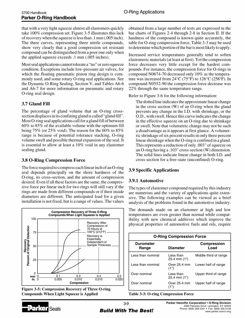
Parker O-Ring Handbook5700 Handbook O-Ring Applications
3-9
Build With The Best!SealsParker Hannifin Corporation • O-Ring Division
2360 Palumbo Drive, Lexington, KY 40509Phone: (859) 269-2351 • Fax: (859) 335-5128
www.parker.com/o-ring
that with a very light squeeze almost all elastomers quicklytake 100% compression set. Figure 3-5 illustrates this lackof recovery when the squeeze is less than .1 mm (.005 inch).The three curves, representing three nitrile compounds,show very clearly that a good compression set resistantcompound can be distinguished from a poor one only whenthe applied squeeze exceeds .1 mm (.005 inches).
Most seal applications cannot tolerate a “no” or zero squeezecondition. Exceptions include low-pressure air valves, forwhich the floating pneumatic piston ring design is com-monly used, and some rotary O-ring seal applications. Seethe Dynamic O-Ring Sealing, Section V, and Tables A6-6and A6-7 for more information on pneumatic and rotaryO-ring seal design.
3.7 Gland Fill
The percentage of gland volume that an O-ring cross-section displaces in its confining gland is called “gland fill”.Most O-ring seal applications call for a gland fill of between60% to 85% of the available volume with the optimum fillbeing 75% (or 25% void). The reason for the 60% to 85%range is because of potential tolerance stacking, O-ringvolume swell and possible thermal expansion of the seal. Itis essential to allow at least a 10% void in any elastomersealing gland.
3.8 O-Ring Compression Force
The force required to compress each linear inch of an O-ringseal depends principally on the shore hardness of theO-ring, its cross-section, and the amount of compressiondesired. Even if all these factors are the same, the compres-sive force per linear inch for two rings will still vary if therings are made from different compounds or if their insidediameters are different. The anticipated load for a giveninstallation is not fixed, but is a range of values. The values
obtained from a large number of tests are expressed in thebar charts of Figures 2-4 through 2-8 in Section II. If thehardness of the compound is known quite accurately, thetable for O-ring compression force, Table 3-3 may be usedto determine which portion of the bar is most likely to apply.
Increased service temperatures generally tend to softenelastomeric materials (at least at first). Yet the compressionforce decreases very little except for the hardest com-pounds. For instance, the compression force for O-rings incompound N0674-70 decreased only 10% as the tempera-ture was increased from 24°C (75°F) to 126°C (258°F). Incompound N0552-90 the compression force decrease was22% through the same temperature range.
Refer to Figure 3-6 for the following information:The dotted line indicates the approximate linear changein the cross section (W) of an O-ring when the glandprevents any change in the I.D. with shrinkage, or theO.D., with swell. Hence this curve indicates the changein the effective squeeze on an O-ring due to shrinkageor swell. Note that volumetric change may not be sucha disadvantage as it appears at first glance. A volumet-ric shrinkage of six percent results in only three percentlinear shrinkage when the O-ring is confined in a gland.This represents a reduction of only .003" of squeeze onan O-ring having a .103" cross-section (W) dimension.The solid lines indicate linear change in both I.D. andcross-section for a free-state (unconfined) O-ring.
3.9 Specific Applications
3.9.1 Automotive
The types of elastomer compound required by this industryare numerous and the variety of applications quite exten-sive. The following examples can be viewed as a briefanalysis of the problems found in the automotive industry.
The demands made on an elastomer at high and lowtemperatures are even greater than normal while compat-ibility with new chemical additives which improve thephysical properties of automotive fuels and oils, require
Figure 3-5: Compression Recovery of Three O-ringCompounds When Light Squeeze is Applied
Compression Recovery of Three O-RingCompounds When Light Squeeze is Applied
CompressionIn.
mm 0.10.005
100
75
50
25
000
0.30.010
0.40.015
Recovery AfterCompression of70 Hours at100°C (212°F)Recovery isEssentiallyIndependent ofSample Thickness
0.50.020
Rec
over
yP
erce
nt o
f Ori
gina
l Del
ectio
n
O-Ring Compression Force
Durometer CompressionRange Diameter Load
Less than nominal Less than Middle third of range25.4 mm (1")
Less than nominal Over 25.4 mm Lower half of range(1")
Over nominal Less than Upper third of range25.4 mm (1")
Over nominal Over 25.4 mm Upper half of range(1")
Table 3-3: O-ring Compression Force

Parker O-Ring Handbook5700 Handbook O-Ring Applications
3-10
Build With The Best!SealsParker Hannifin Corporation • O-Ring Division
2360 Palumbo Drive, Lexington, KY 40509Phone: (859) 269-2351 • Fax: (859) 335-5128
www.parker.com/o-ring
continuous improvement in elastomeric compounds forautomotive service.
The selection of the proper O-ring compound depends onthe temperature at the sealing interface and of the contactmedium. Each group of elastomers have a working range oftemperatures.
The low temperature requirements for many automotiveapplications are often below the brittleness point for elas-tomers like FKM, ACM and NBR. In static applications,leakage at low temperatures may occur because of O-ringdeformation and the high viscosity of the sealed medium.The critical temperature often is bridged when the sealwarms quickly in service.
3.9.2 Engine
See Table 3-4.
General requirements:
Temperature: -40°C to 125°C (-40°F to 250°F)(sometimes higher)
Medium: Engine oil, cooling water, fuel, hot air andmixtures of these media
3.9.3 Brake System
General requirements:
Temperature: -40°C to 150°C (-40°F to 302°F)
Medium: Synthetic brake fluid (DOT3, DOT4,DOT5) with glycol or glycol-ether base toDepartment of Transportion and SAErecommendations
3.9.4 Fuel System
Standard, super and diesel fuels are used in normal com-mercial vehicles. Fuels are more aggressive than mineraloils and cause higher swelling of the elastomer whichincreases with temperature. Swelling of an elastomer infuel is, however, generally reversible when the absorbedfuel vaporizes completely. When parts of a compound aredissolved or leached out of the elastomer however, shrink-age takes place which is permanent. If a nitrile-basedcompound is required, a compound must be selected whichcontains minimum amounts of plasticisers, anti-aging oranti-ozone additives. By careful selection of the seal com-pound, the tendency to shrinkage or cold brittleness isavoided.
3.9.5 Fuels for Automobile Engines
There are several automotive fuels on the market; leadedand unleaded gasoline, each type of which can vary incomposition, and gasohol. Gasohol is a mixture of gasolinewith 10 to 20% alcohol. The alcohol may be either ethyl
Figure 3-6: O-ring Linear vs. Volume Change Relationship
(also called ethanol or grain alcohol) or methyl (methanolor wood alcohol). The most commonly used gasohol in theUnited States consists of unleaded gasoline plus 10%ethanol.
The best rubber compound to use depends not only on thefuel itself, but also on the temperature range anticipated andthe type of usage; i.e. whether in a static or a dynamic
O-Ring Linear vs. Volume Change Relationship
LinearShrinkage
Percent
VolumeShrinkage
Percent
Linear Expansion — Percent
Volu
me
Sw
ell —
Per
cent
15 10
100
90
80
70
60
50
40
30
20
10
10
20
5
5 10 15 20 25 30 35 40Fixed I.D.
Free O-Ring Fixed O.D.
Engine ApplicationsTemperature Compounds
Range ASTMApplication Medium °C (°F) D1418 ParkerMotor oil SAE- -35°C to 110°C NBR N0674-70Oil filter Oils (-31°F to 230°F)
-30°C to 120°C NBR N0951-75(-22°F to 248°F)-25°C to 200°C FKM V1164-75(-13°F to 392°F)
-25° to 150° ACM A1107-70(-13°F to 392°F)
Wet Water/ -30°C to 100°C NBR N0951-75cylinders Oil (-22°F to 212°F)(Diesel) -25°C to 120°C FKM V1164-70
(-13°F to 248°F)
Air- Air/ -35°C to 90°C NBR N0674-70filter Fuel (-31°F to 194°F)
-60° to 210° VMQ S1224-70(140°F to 410°F)
Table 3-4: Engine Applications
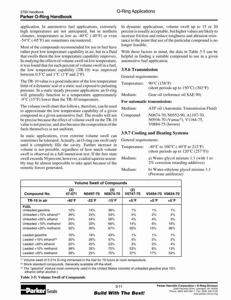
Parker O-Ring Handbook5700 Handbook O-Ring Applications
3-11
Build With The Best!SealsParker Hannifin Corporation • O-Ring Division
2360 Palumbo Drive, Lexington, KY 40509Phone: (859) 269-2351 • Fax: (859) 335-5128
www.parker.com/o-ring
application. In automotive fuel applications, extremelyhigh temperatures are not anticipated, but in northernclimates, temperatures as low as -40°C (-40°F) or even-54°C (-65°F) are sometimes encountered.
Most of the compounds recommended for use in fuel haverather poor low temperature capability in air, but in a fluidthat swells them the low temperature capability improves.In studying the effects of volume swell on low temperature,it was found that for each percent of volume swell in a fuel,the low temperature capability (TR-10) was improvedbetween 0.5°C and 1°C (1°F and 2°F).
The TR-10 value is a good indicator of the low temperaturelimit of a dynamic seal or a static seal exposed to pulsatingpressure. In a static steady pressure application, an O-ringwill generally function to a temperature approximately-9°C (15°F) lower than the TR-10 temperature.
The volume swell chart that follows, therefore, can be usedto approximate the low temperature capability of a givencompound in a given automotive fuel. The results will notbe precise because the effect of volume swell on the TR-10value is not precise, and also because the composition of thefuels themselves is not uniform.
In static applications, even extreme volume swell cansometimes be tolerated. Actually, an O-ring can swell onlyuntil it completely fills the cavity. Further increase involume is not possible, regardless of how much volumeswell is observed in a full immersion test. If the free stateswell exceeds 50 percent, however, a radial squeeze assem-bly may be almost impossible to take apart because of theosmotic forces generated.
In dynamic applications, volume swell up to 15 or 20percent is usually acceptable, but higher values are likely toincrease friction and reduce toughness and abrasion resis-tance to the point that use of the particular compound is nolonger feasible.
With these factors in mind, the data in Table 3-5 can behelpful in finding a suitable compound to use in a givenautomotive fuel application.
3.9.6 Transmission
General requirements:
Temperature: 90°C (158°F)(short periods up to 150°C) (302°F)
Medium: Gear oil (reference oil SAE 90)
For automatic transmission:
Medium: ATF oil (Automatic Transmission Fluid)
Compound: N0674-70, N0552-90, A1107-70,N0936-70 (Vamac®), V1164-75,V0884-75 (brown)
3.9.7 Cooling and Heating Systems
General requirements:
Temperature: -40°C to 100°C (-40°F to 212°F)(short periods up to 120°C (257°F))
Medium: a) Water-glycol mixture 1:1 (with 1 to2% corrosion retarding additives)
Medium: b) Water-ethylene glycol mixture 1:1(Prestone antifreeze)
Volume Swell of Compounds
(2) (2) (2)Compound No. 47-071 N0497-70 N0674-70 V0747-75 V0494-70 V0834-70
TR-10 in air -40°F -23°F -15°F +5°F +5°F +5°F
FUELUnleaded gasoline 12% 14% 36% 1% 1% 1%Unleaded +10% ethanol(3) 26% 24% 53% 5% 2% 2%Unleaded +20% ethanol 24% 24% 56% 4% 4% 5%Unleaded +10% methanol 35% 33% 66% 14% 6% 16%Unleaded +20% methanol 32% 30% 67% 26% 15% 36%
Leaded gasoline 16% 16% 43% 1% 1% 1%Leaded +10% ethanol(3) 30% 26% 57% 5% 2% 2%Leaded +20% ethanol 22% 20% 53% 3% 3% 4%Leaded +10% methanol 38% 35% 72% 23% 6% 13%Leaded +20% methanol 39% 25% 75% 37% 17% 53%
(1) Volume swell of 2-214 O-ring immersed in the fuel for 70 hours at room temperature.(2) Stock standard compounds. Generally available off-the-shelf.(3) The “gasohol” mixture most commonly used in the United States consists of unleaded gasoline plus 10%
ethanol (ethyl alcohol.)
Table 3-5: Volume Swell of Compounds

Parker O-Ring Handbook5700 Handbook O-Ring Applications
3-12
Build With The Best!SealsParker Hannifin Corporation • O-Ring Division
2360 Palumbo Drive, Lexington, KY 40509Phone: (859) 269-2351 • Fax: (859) 335-5128
www.parker.com/o-ring
Compound Recommendation for Refrigerants
FluorinatedHydrocarbons ASTMRefrigerant (R) D1418 Parker
11 NBR N0674-7012 CR C0873-7012 and ASTM oil no. 2 FKM V1164-75(mixed 50:50)12 and Suniso 4G FKM V1164-75(mixed 50:50)
13 CR C0873-7013 B1 CR C0873-7014 CR C0873-7021 CR C0873-7022 CR C0873-70
22 and ASTM oil no. 2 CR C0873-70(mixed 50:50)31 CR C0873-7032 CR C0873-70112 FKM V1164-75
113 CR C0873-70114 CR C0873-70114 B2 CR C0873-70115 CR C0873-70502 CR C0873-70134a CR C0873-70
BF (R112) FKM V1164-75C318 CR C0873-70K-152a CR C0873-70K-142b CR C0873-70MF (R11) NBR N0674-70PCA (R113) CR C0873-70TF (R113) CR C0873-70
Table 3-6: Compound Recommendation for Refrigerants
3.9.8 Air Conditioning
Automotive A/C units are almost exclusively charged withrefrigerant R134a, whereas existing units are generallyfilled with the older (and now banned in US) R12 Freonrefrigerant.
Special oils are added to the refrigerant in order to lubricatethe compressor: R134a systems use mostly polyalkyleneglycol oils, whereas R12 systems employ mostly mineral oils.
General requirements:
Temperature: -40°C to 80°C (-40°F to 175°F)
Medium: refrigerant R134arefrigerant R12polyalkylene glycol oilmineral oil
3.9.9 Power Steering Systems
General requirements:
Temperature: Up to 120°C (-40°F to 257°F)(short periods up to 150°C (302°F))
Medium: ATF oil (Pentosine)
Oils are preferred which tend to have a constant viscosityover a wide temperature range. These highly developed oilscan be very aggressive.
FKM or ACM based materials are often are preferred whenhigh operating temperatures are involved.
3.9.10 Refrigeration and Air Conditioning
Seals used in cooling systems should be fully compatiblewith the refrigerant. Refrigerants often are coded “R” andconsist of fluids based on fluorinated and chlorinated hy-drocarbons.
Trade names, e.g. Freon, Frigen, Kaltron are used togetherwith the type number.
Examples:• R13 corresponds to Freon 13 and Kaltron 13• R13 B1 corresponds to Freon 13 B1, Frigen 13 B1 and
Kaltron 13 B1
Fire extinguishers are propelled with Halon R1301 corres-ponding to Freon 13 B1.
Several of these refrigerants also are used as propellants inaerosol containers. Further information on compounds canbe found in the Fluid Compatibility Tables in Section VII.See Table 3-6.
3.9.11 Food, Beverage and Potable Water
The Food and Drug Administration (FDA) has establisheda list of rubber compounding ingredients which tests have
indicated are neither toxic nor carcinogenic (cancer pro-ducing). Rubber compounds produced entirely from theseingredients and which also pass the FDA extraction testsare said to “meet the FDA requirements.” (The FDA doesnot approve rubber compounds. It is the responsibility ofthe manufacturer to compound food grade materials fromthe FDA list of ingredients and establish whether they passthe necessary extraction requirements.)
3-A Sanitary Standards have been formulated by the UnitedStates Public Health Service, the International Associationof Milk Food and Environmental Standards, and the Dairyand Food Industries Supply Association. A similar docu-ment, E-3A Sanitary Standards, was later formulated bythis same group plus the United States Department ofAgriculture and the Institute of American Poultry Indus-tries. The 3-A standards are intended for elastomers to beused as product contact surfaces in dairy equipment, whilethe E-3A standards are intended for elastomers used asproduct contact surfaces in egg processing equipment. Therequirements of the two specifications are essentially iden-tical, the intent in each case being to determine whetherrubber materials are capable of being cleaned and receivingan effective bactericidal treatment while still maintaining
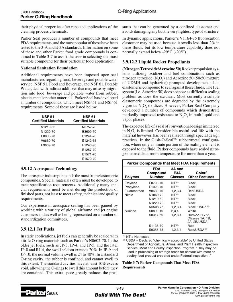
Parker O-Ring Handbook5700 Handbook O-Ring Applications
3-13
Build With The Best!SealsParker Hannifin Corporation • O-Ring Division
2360 Palumbo Drive, Lexington, KY 40509Phone: (859) 269-2351 • Fax: (859) 335-5128
www.parker.com/o-ring
their physical properties after repeated applications of thecleaning process chemicals.
Parker Seal produces a number of compounds that meetFDA requirements, and the most popular of these have beentested to the 3-A and E-3A standards. Information on someof these and other Parker food grade compounds is con-tained in Table 3-7 to assist the user in selecting the mostsuitable compound for their particular food application.
National Sanitation Foundation
Additional requirements have been imposed upon sealmanufacturers regarding food, beverage and potable waterservice. NSF 51, Food and Beverage, and NSF 61, PotableWater, deal with indirect additives that may arise by migra-tion into food, beverage and potable water from rubber,plastic, metal or other materials. Parker Seal has developeda number of compounds, which meet NSF 51 and NSF 61requirements. Some of these are listed below.
NSF 51 NSF 61Certified Materials Certified Materials
N1219-60 N0757-70N1220-70 E3609-70E0883-70 E1244-70V0680-70 E1242-65E3609-70 E1240-90
E1257-70E1571-70E1570-70
3.9.12 Aerospace Technology
The aerospace industry demands the most from elastomericcompounds. Special materials often must be developed tomeet specification requirements. Additionally many spe-cial requirements must be met during the production offinished parts, not least to meet safety, technical and qualityrequirements.
Our experience in aerospace sealing has been gained byworking with a variety of global airframe and jet enginecustomers and as well as being represented on a number ofstandardization committees.
3.9.12.1 Jet Fuels
In static applications, jet fuels can generally be sealed withnitrile O-ring materials such as Parker’s N0602-70. In theolder jet fuels, such as JP-3, JP-4, and JP-5, and the laterJP-8 and RJ-4, the swell seldom exceeds 20%. In JP-9 andJP-10, the normal volume swell is 24 to 40%. In a standardO-ring cavity, the rubber is confined, and cannot swell tothis extent. The standard cavities have at least 10% excessvoid, allowing the O-rings to swell this amount before theyare contained. This extra space greatly reduces the pres-
sures that can be generated by a confined elastomer andavoids damaging any but the very lightest type of structure.
In dynamic applications, Parker’s V1164-75 fluorocarbonelastomer may be used because it swells less than 2% inthese fluids, but its low temperature capability does notnormally extend below -29°C (-20°F).
3.9.12.2 Liquid Rocket Propellants
(Nitrogen Tetroxide/Aerozine 50) Rocket propulsion sys-tems utilizing oxidizer and fuel combinations such asnitrogen tetroxide (N
2O
4) and Aerozine 50 (50/50 mixture
of UDMH and hydrazine) prompted development of anelastomeric compound to seal against these fluids. The fuelsystem (i.e. Aerozine 50) does not pose as difficult a sealingproblem as does the oxidizer. Most currently availableelastomeric compounds are degraded by the extremelyvigorous N
2O
4 oxidizer. However, Parker Seal Company
developed a number of compounds which demonstratemarkedly improved resistance to N
2O
4 in both liquid and
vapor phases.
The expected life of a seal of conventional design immersedin N
2O
4 is limited. Considerable useful seal life with the
material however, has been realized through special designpractices. In the Gask-O-Seal™ rubber/metal configura-tion, where only a minute portion of the sealing element isexposed to the fluid, Parker compounds have sealed nitro-gen tetroxide at room temperature for more than a year.
Parker Compounds that Meet FDA RequirementsFDA 3A and
Compound E3A Color/Polymer Number Classes Other Features
Ethylene E0798-70 NT (1) BlackPropylene E1028-70 NT (1) BlackFluorocarbon V0680-70 1,2,3,4 Red/USDANitrile N1069-70 NT (1) Black
N1219-60 NT (1) BlackN1220-70 NT (1) BlackN0508-75 1,2,3,4 Black, USDA (2)
Silicone S0802-40 2,3,4 WhiteS0317-60 1,2,3,4 Rust/ZZ-R-765,
Classes 1A, 1B,2A, 2B/USDA
S1138-70 NT (1) RustS0355-75 1,2,3,4 Rust/USDA (2)
(1) NT = Not tested (2) USDA = Declared “chemically acceptable” by United States
Department of Agriculture, Animal and Plant Health InspectionService, Meat and Poultry Inspection Program. “They may beused in processing or storage areas for contact with meat orpoultry food product prepared under Federal inspection...”
Table 3-7: Parker Compounds That Meet FDARequirements

Parker O-Ring Handbook5700 Handbook O-Ring Applications
3-14
Build With The Best!SealsParker Hannifin Corporation • O-Ring Division
2360 Palumbo Drive, Lexington, KY 40509Phone: (859) 269-2351 • Fax: (859) 335-5128
www.parker.com/o-ring
Data on Radiation Resistant Compounds
Comp. Steam & SiliconeSet at Max. Water Fluid
Compound Polymer 107 Rads (1) Temp. (2) Resistance Resistance
S0604-70 Silicone 20.0% 204°C (400°F) Poor PoorN0674-70 Nitrile 24.3% 149°C (300°F) OK to 49°C (120°F) GoodN0741-75 Nitrile 24.3% 149°C (300°F) OK to 49°C (120°F) GoodE0740-75 Ethylene Propylene 28.6% 177°C (350°F) Good GoodS0455-70 Silicone (Hi Temp) 31.4% 177°C (350°F) Poor PoorE0515-80 Ethylene Propylene 46.6% 149°C (300°F) Good GoodP0642-70 Polyurethane 55.2% 82°C (180°F) Poor GoodA0607-70 Polyacrylate 61.5% 149°C (300°F) Poor GoodV0747-75 Fluorocarbon 66.7% 204°C (400°F) Poor GoodL0677-70 Fluorosilicone 67.6% 204°C (400°F) Poor Good
(1) Compression set after exposure to 107 rads of gamma radiation at room temperature. The lower values arepreferred. If over 40%, use only at lower dosage level.
(2) Temperature at which .139 cross section ring takes a 90% compression set after 1000 hours when not exposedto radiation or fluids.
Note: Some of these compounds may no longer be available.
Table 3-8: Data on Radiation Resistant Compounds
3.9.13 Nuclear Technology
Elastomers which are compounded for exposure to radia-tion must satisfy stringent quality and material qualifica-tion tests. In addition to resisting radiation, the elastomeralso must be compatible with the contact medium under theworking environment (temperature, pressure, etc).
In the majority of these applications, the radiation dosagelevel remains below 106 rad, a level normally attained afteryears of operation. Practically all elastomers suffer nochange of their physical properties at radiation levels up to1 M rad (= 106 rad = 104 J/kg). Parker has developedcompounds with resistance to radiation levels of 107 rad.
Water and steam are common media in nuclear applications.
Typical nuclear operating conditions are:
Temperature: 180°C (350°F)Irradiation: 107 rad
3.9.14 Radiation
One of the most important properties if an elastomer usedas an O-ring seal is its resistance to compression set. Onexposure to gamma radiation, it is compression set that ismost severely affected. After experiencing 1 x 10⁸ rads, allelastomers tested had taken over 85% set, enough loss of“memory” that leakage would be expected. At 1 x10⁷ rads,there were big differences between compounds, while at1 x 106 rads, the effects on all compounds were minor. It istherefore in the range of 1 x 10⁷, that an O-ring compoundmust be selected with care, while at higher levels theyshould not be considered, and at lower levels factors otherthan radiation will be more significant.
In a reactor, seals are often exposed to hot water, steam, hotair, silicone fluids or other influences in addition to theradiation. The total effect is probably greater than a simpleaddition of the individual effects, and it is therefore impor-tant to test a seal in conditions similar to those it willencounter in service. Because effects vary with the indi-vidual compound, it is important that the exact compoundbe specified, and not merely the type of polymer.
Table 3-8 gives data to aid in selecting the most promisingcompounds to test for many combinations of conditions.
3.9.15 Chemical Processing/Oil Field Technology
Applications in the offshore industry pose new and uniqueproblems for seal manufacturers. Working conditions arevery difficult involving:
• Aggressive contact media• High pressures• Wide range of temperatures
Critical conditions occur in connection with:• Oil additives causing chemical attack• Explosive decompression• Clearance gap extrusion at high pressure• High and low temperatures
Contact media are gas, oil, water (sea water, ground water),sour gas, CO
2, steam, rinsing water, lubricants (additives in
lubricants as rust inhibitors), etc.
Working conditions vary greatly to location and function.

Parker O-Ring Handbook5700 Handbook O-Ring Applications
3-15
Build With The Best!SealsParker Hannifin Corporation • O-Ring Division
2360 Palumbo Drive, Lexington, KY 40509Phone: (859) 269-2351 • Fax: (859) 335-5128
www.parker.com/o-ring
Temperatures: up to 225°C (450°F) plus peaks
Working pressures: 100 to 1000 Bar and higher(1450 PSI to 14500 PSI andhigher)
Contact our Inside Sales Engineering Department regard-ing the above and more difficult conditions.
3.9.16 Fungus-Resistant Compounds
Both the extreme environmental conditions experienced bythe military and efforts in space have focused attention onmany previously overlooked facets of hardware. Amongthese is the ability of materials to resist degradation causedby fungus. Fungus is a problem in tropical regions such assoutheast Asia. A number of Parker compounds have beensubmitted to an independent laboratory for fungus resis-tance exposure tests. The results of this study document thatthe Parker compounds shown in Table 3-9 are non-nutrientto fungus as defined by MIL-STD-810D, Method 508.3.
With the possible exceptions of natural rubber and polyure-thane, the base polymers for elastomers are normally non-nutrient to fungi. Nevertheless, there are compounds thatwill support fungus growth because they contain nutrienttype ingredients. The plasticizer used is of particular impor-tance in this respect. By studying all the ingredients of aparticular compound, a chemist can predict quite accuratelywhether it will support fungus growth, without conductinga test. Therefore, if it is desirable to use some compound notlisted below in an application that requires a non-nutrientmaterial, contact Parker’s Inside Sales Engineering Depart-ment to determine whether the compound is a good candi-date for the application.
Fungus Tests on CompoundsFungus testing per MIL-STD-810D, Method 508.3
Non-Nutrient Supportsto Fungus Growth Fungus Growth
ButylB0612-70NeopreneC0365-45C0873-70C1124-70
EthylenePropyleneE0692-75E0740-75E0515-80E0540-80
Buna SG0244-70
NitrileN0545-40N0299-80N0406-60N0525-60N0506-6547-071N0103-70N0497-70N0602-70N0674-70N0818-70N0304-75N0951-75N0507-90N0552-90
SiliconeS0595-80S0317-60S0613-60S0455-70S0604-70S0355-75S0614-80
FluorocarbonV0680-70V0747-75V1164-75V0709-90
FluorosiliconeL1120-70
PolyacrylateA1107-70
NeopreneC0267-50
EthylenePropyleneE0603-70E0652-90
NitrileN1069-70N0756-75
PolyurethaneP0642-70P0648-90
Note: Some of these compounds may no longer be available
Table 3-9: Fungus Tests on Compounds Table 3-10: Compounds for Hydraulic Fluids
Compounds for Hydraulic Fluids
Temp. Range O-Ring Compounds
High-Water-Base Fluids (95-5 Fluids)4°C to 49°C N0674-70, nitrile(40°F to 120°F) E1253-80, ethylene propylene
Hydrocarbon Base Hydraulic Fluids(including petroleum base)
-54°C to 149°C -34°C to 121°C (-30°F to 250°F),(-65°F to 300°F) N0674-70, nitrile
-29°C to 135°C (-20°F to 275°F),N0951-75, nitrile
-54°C to 135°C (-65°F to 275°F),N0756-75, nitrile
-26°C to 204°C (-15°F to 400°F),V1164-75, fluorocarbon
-26°C to 204°C (-15°F to 400°F),V1226-75, fluorocarbon
Phosphate EstersAircraft types (alkyl phosphate esters)
-54°C to 149°C E1235-80, ethylene propylene(-65°F to 300°F) (NAS1613)
E0692-75, ethylene propyleneIndustrial types (aryl phosphate esters)
-34°C to 93°C E1253-80, ethylene propylene(-30°F to 200°F) V1164-75, fluorocarbon
V1226-75, fluorocarbon
Phosphate Ester-Petroleum Oil Blends-1°C to 100°C V1164-75, fluorocarbon(30°F to 212°F) V1226-75, fluorocarbon
Silicate Esters-54°C to 288°C -26°C to 204°C (-15°F to 400°F),(65°F to 550°F) V1164-75, fluorocarbon
-26°C to 204°C (-15°F to 400°F),V0884-75, fluorocarbon
-54°C to 149°C (65°F to 300°F),C0873-70, neoprene
Silicone Hydraulic Fluids38°C to 288°C 38°C to 177°C (-100°F to 350°F),(-100°F to 550°F) L1120-70 fluorosilicone (static only)
-54°C to 149°C (-65°F to 300°F),E1253-80, ethylene propylene
-26°C to 204°C (-15°F to 400°F),V1164-75, fluorocarbon
-26°C to 204°C (-15°F to 400°F),V1226-75, fluorocarbon (brownChromassure)
Water-Glycol-18°C to 60°C E1253-80, ethylene propylene(0°F to 140°F) N0674-70, nitrile (limited life as dynamic(But wider range seal anticipated above 43°C (110°F))as a coolant) N0951-75, nitrile (for higher temperature
coolant use)
Water-in-Oil Emulsions (“Invert” emulsions)-12°C to 49°C N0674-70, nitrile(10°F to 120°F)
Note: Due to variations in each type of fluid, and the manyvariables possible in the application of O-rings, these compoundlistings are intended only as general guides. Users must testunder their own operating conditions to determine the suitabilityof any compound in a particular application.

Parker O-Ring Handbook5700 Handbook O-Ring Applications
3-16
Build With The Best!SealsParker Hannifin Corporation • O-Ring Division
2360 Palumbo Drive, Lexington, KY 40509Phone: (859) 269-2351 • Fax: (859) 335-5128
www.parker.com/o-ring
Types of Non-Flammable Hydraulic Fluids
Type ofHydraulic Fluid Content Application
Hydraulic fluid HFA Oil in water Hydraulic fluid e.g.emulsion for hydraulic presses
Hydraulic fluid HFB Water in oil Hydraulic fluid e.g.emulsion for hydraulic presses
Hydraulic fluid HFC Water polymer Fire risk systems tosolutions max. 60°C at
low pressure
Hydraulic fluid HFD Waterless For fire risk systemssynthetic fluid at high temperatures
and pressures
Table 3-11: Types of Non-Flammable Hydraulic Fluids
3.9.17 Hydraulic Fluids
There are so many types of hydraulic fluids that no singleO-ring compound can be used to seal all of them. If aspecific fluid is not listed in Section VII, a good candidateO-ring material can be selected from Table 3-10 if the typeof the hydraulic fluid is known. Of course, it is important toselect a seal compound having a temperature range that issuitable for the application.
3.9.17.1 Fire-Resistant Hydraulic Fluids
When mineral oils represent a high fire risk, fire-resistanthydraulic fluids are used. Three groups of such fluids are:
• Water emulsions (HFA and HFB groups)• Water solutions (HFC)• Water-free synthetic fluids (HFD)
The types of fire-resistant hydraulic fluids are presented inTable 3-11.
Fluids containing water rely on their water content to preventfire. To remain effective, such fluids must be regularlychecked and their water concentration maintained. Work-ing temperatures are limited to between 50°C and 65°C(120°F to 150°F) because water easily evaporates at highertemperatures. All fluids containing water have one com-mon feature: they have a negative effect upon bearings.
According to ISO Specification 6071, HFA, HFB and HFChydraulic fluids are differentiated further by the suffixletters C, M, E and S:
• C indicates that no wear inhibitor is present• M indicates that a wear inhibitor is present• E indicates a mineral oil based HFA fluid• S indicates a synthetic HFA fluid
Table 3-12 shows a comparison of the most importantproperties of the four groups of non-flammable fluidstogether with the recommended type of elastomer.
3.9.17.1.1 HFA Fluids
HFA fluids contain more than 80% water. In practice 95%to 98% water is more common, the balance being “concen-trates” which improve wear and corrosion resistance.
The relationship between water content and concentrateoffers the greatest threat to the proper function of HFAfluids. The local water supply is not only different from onearea to the next, but its various constituents may cause thehardness to vary. The operating solution is mixed by theuser and not by the manufacturer. HFA concentrates canhave mineral oil or synthetic oil bases.
3.9.17.2 Concentrates Containing Mineral Oils(Oil-in-Water-Solutions)
Oil is not soluble in water. Only by employing emulsifiersit is possible to bring about a stable oil-in-water-solution.The level of concentrates is limited by the stability of theemulsion.
Mineral oil concentrates can contain practically all types ofchemical additives that have thus far been developed.When the water evaporates, mineral oil remains behind,containing all required anti-corrosion additives. The con-centrates are mostly based on naphthenic oils and can causeproblems with certain O-ring compounds. Such emulsionshave been used as hydraulic press fluids for decades. Ingeneral, emulsions take longer to filter.
With these kinds of fluids there is a great risk of micro-bacteriological growth which can lead to problems. Suchgrowth however, can be brought under control withoutdifficulty by adding a biocide to the mixture.
3.9.17.3 Micro-Emulsions
Recently, new synthetic concentrates, which are similar tooils, have been developed which form micro-emulsionswhen mixed by 5% with water. This is neither a truesolution nor an emulsion, but can be better described as ahighly stable colloidal suspension of high viscosity oildrops in water.
The concentrate contains both water and oil soluble, wearresistant additives which form a high-pressure resistantfilm with good lubricating properties. They are not prone tothe micro-biological attack, and have a useful life of morethan one year.
Concentrates currently available at this time are limited to100 Bar (1450 PSI) working pressure and are mostly usedin automated production lines, industrial robots, etc.
3.9.17.4 Synthetic HFA Concentrates (Solutions)
Recently a number of synthetic HFA concentrates havebeen developed which form a stable solution in water and

Parker O-Ring Handbook5700 Handbook O-Ring Applications
3-17
Build With The Best!SealsParker Hannifin Corporation • O-Ring Division
2360 Palumbo Drive, Lexington, KY 40509Phone: (859) 269-2351 • Fax: (859) 335-5128
www.parker.com/o-ring
are also suitable carriers of semi-soluble additives whosepurpose is to protect metal components such as brass andcopper.
These fluids can be filtered finely as required because theyare in complete solution. Should the water evaporate how-ever, the residual fluid has a high pH value, which maycause corrosion.
The most important physical properties of HFA fluidsdepend on their water proportion and vary greatly frommineral oils. As described above, wear and lubricatingproperties can be greatly improved by the addition ofsuitable concentrates. In spite of this, the working life of ahydraulic system using HFA fluid is significantly shorterthan of a system using conventional hydraulic oils.
Oil based hydraulic systems are increasingly being re-placed by HFA fluids. The tendency to leakage of theselow-viscosity fluids has caused a search for additives thatwould increase the fluid’s viscosity. The working tempera-ture ranges from 5°C to 55°C (42°F to 130°F).
3.9.17.5 HFC Fluids
HFC hydraulic fluids consist of a solution of polyethyleneand polypropylene glycols in a proportion of between 35%and 55%. The two glycols behave differently, bringingabout a wide variation in the fluid’s properties.
While polyethylene glycols exhibit relatively high resis-tance to shear, tests have shown that they suffer damage byshearing of the chains after only 2000 to 3000 workinghours. Most elastomer compounds that are compatible withmineral oils also can be used in HFC fluids (NBR forexample). Certain FKM compounds are not compatiblewith HFC fluids.
The wear resistant properties and viscosity of HFC fluids isgood and corrosion may be controlled by additives. Thetemperature range is an improvement over mineral oil basedfluids. Exposed bearings however, still remain very suscep-tible to corrosion due to high water content and the workinglife of equipment is thereby shortened. This is especiallytrue with working pressures over 200 Bar (2900 PSI).
HFC fluids are regarded as special refuse and should behandled accordingly. Working temperature ranges from-25°C to 60°C (-14°F to 140°F).
Properties of the Four Groups of Non-Flammable Fluids
Reference
Properties HFA/HFB HFC HFD
kinematic viscosity (mm2/s) to 50°C (122°F) 0.3 to 2 20 to 70 12 to 50
viscosity/temperature relationship good very good bad
density at 15°C (59°F) ca. 0.99 1.04 to 1.09 1.15 to 1.45
temperature range 3°C to 55°C -25°C to 60°C -20°C to 150°C(37°F to 131°F) (-13°F to 140°F) (-4°F to 302°F)
water content (weight %) 80 to 98 35 to 55 none
stability emulsion poor very good very goodsolution very good
life of bearings 5 to 10% 6 to 15% 50 to 100%
heat transfer excellent good poor
lubrication acceptable good excellent
corrosion resistance poor to acceptable good excellent
combustion temperature not possible after vaporizing ca. 600°Cof water under 1000°C (1832°F) (1112°F)
environmental risk emulsion: used oil special waste special wastesynth.: dilution
regular inspection pH-level viscosity viscosityconcentration water content neutral pHwater hardness pH-level spec. gravitymicro-organisms
seal material NBR, FKM, AU NBR FKM, EPDM1)
1) only for pure (mineral oil free) phosphate-ester (HFD-R)
Table 3-12: Properties of the Four Groups of Non-Flammable Fluids

Parker O-Ring Handbook5700 Handbook O-Ring Applications
3-18
Build With The Best!SealsParker Hannifin Corporation • O-Ring Division
2360 Palumbo Drive, Lexington, KY 40509Phone: (859) 269-2351 • Fax: (859) 335-5128
www.parker.com/o-ring
ASTM D395 Method B .139 Cross-Section O-ring25% Deflection 70 Hours @ Temperature
Figure 3-7: Compression Set Resistance of CompoundN0951-75
100°C(212°F)
100
90
80
70
60
50
40
30
20
10
0
% o
f Ori
gina
l Def
lect
ion
125°C(257°F)
150°C(302°F)
Conventional Nitrile Compound
Compound N0951-75
Compression Set Resistance of Compound N0951-75
3.9.17.6 HFD Fluids
This group of hydraulic fluids consists of pure synthetic,water-free fluid and does not suffer from most of thepreviously mentioned difficulties. On the down side how-ever, compatibility with most seal materials is rather limited.
The earliest developments in HFD fluids have disappearedfrom the market because they were extremely poisonous.Their place has been taken by pure phosphate esters, bothsynthetic and natural, which are essentially non-toxic.Although much easier to handle, these materials have a verysteep viscosity/temperature relationship curve which makesthe working range of temperature very narrow; this meansthat more cooling capacity is necessary to avoid overheat-ing the system.
The fluid can be used at pressures in the range of 300 to 350Bar (4350 to 5075 PSI) and represents the most expensivehydraulic fluid on the market. Disposal is problem-free butmust still be classified as special refuse.
HFD fluids can be used at temperatures between -20°C and150°C (-5°F and 300°F).
3.10 Temperature Extremes
3.10.1 High Temperature
The fluorocarbons are the most useful for high temperaturesealing applications. In a 1000 hour air age test at 204°C(400°F), Parker’s fluorocarbon compound V0747-75 tooka 66% set, leaving enough recovery to continue sealing formany additional hours at that temperature. At 232°C (450°F),however, the anticipated useful life is reduced to approxi-mately 336 hours.
The effect of the environment must be carefully assessed.In the presence of hot water or steam, the fluorocarbonstend to harden and take a premature set. Under theseconditions, ethylene propylene is generally superior tofluorocarbon.
High temperature silicones, such as Parker’s S0455-70,appear superior to the fluorocarbons in air aging tests, butthis is true only when the test specimen is exposed tocirculating air.
Among the nitrile compounds that provide good resistanceto petroleum fluids, adequate low temperature properties,good tensile strength, and good abrasion resistance fordynamic applications, compound N0951-75 has the besthigh temperature properties. It is recommended for tem-peratures up to 135°C (275°F) in air or petroleum oil. Itsrecommended low temperature limit is -4°C (25°F).Figure 3-7, showing compression set values of this com-pound at various temperatures, demonstrates its fine hightemperature capabilities.
Where media compatibility is not optimum, elevated tem-peratures are additionally dangerous.
As a direct comparison, Table 3-13 shows the maximumlong-term temperature limits in a compatible contactmedium.
3.10.2 Low Temperature
When cooled, elastomer compounds lose their elasticity. Atvery low temperatures they harden and have glasslikebrittleness, and may shatter if struck a sharp blow. As longas they are not mechanically disturbed, they remain intact,and upon return to normal temperatures, regain their origi-nal properties, the condition being fully reversible.
The low temperature flexibility of a given compound can beslightly improved if a contact medium causes swelling andsoftening. Softening can occur through dissolving of plas-ticizer.
As indicated by the Fluid Compatibility Tables in SectionVII, silicone (S1224-70) and fluorosilicone (L1120-70)should be selected for low temperature applications. Thesecompounds have poor wear resistant properties and arerecommended only for static applications. Other elastomertypes with good cold flexibility are CR, EPDM, ECO andspecial NBR compounds.
The Fluid Compatibility Tables can be used only as aguideline. The actual lifetime of a seal at low temperaturedepends on the application and on the medium to be sealed.
Temperature at the TR-10 point should be taken for allelastomers to determine a minimum functional tem-perature.

Parker O-Ring Handbook5700 Handbook O-Ring Applications
3-19
Build With The Best!SealsParker Hannifin Corporation • O-Ring Division
2360 Palumbo Drive, Lexington, KY 40509Phone: (859) 269-2351 • Fax: (859) 335-5128
www.parker.com/o-ring
In practice, a static seal may have a minimum functionaltemperature of about 15°C (-9°F) lower than the TR-10point, assuming a correctly designed gland.
When air or other gases must be contained at temperaturesbelow -54°C (-65°F) (the low temperature limit recom-mended for most silicones) compound S0383-70 may beused to reach temperatures to -115°C (-175°F) or lower.
If the permeability rate of silicones is thought to be too highfor the application, bear in mind that the rate decreases asthe temperature goes down. For applications requiringmoderately high temperatures as well as low, it is some-times feasible to use two O-rings, S0383-70 to maintain theseal at the extreme low temperature plus a butyl or fluoro-carbon to reduce permeability when the seal is warmer.
If a low temperature seal must have resistance to a fluid thatattacks silicone, the answer may be a fluorosilicone. Thismaterial has excellent resistance to a wide range of fluids,is usable up to 177°C (350°F) or higher in many applica-tions, and will often seal at temperatures as low as -73°C(-100°F). Its primary disadvantage is its lack of toughness,giving it limited usefulness as a dynamic seal, yet in certaindynamic applications, fluorosilicone O-rings have servedwell as springs to activate a U-type shell of fluorocarbonelastomer or other wear resistant material.
Other compounds will often seal at temperatures belowtheir normal low temperature limit by increasing the squeeze.
This procedure, however, is generally limited to static facetype designs, as a heavy squeeze makes a radial sealdifficult to assemble.
Where temperatures do not go below -40°C (-40°F), O-ringsin Parker’s low temperature fluorocarbon compound,V0835-75, can be utilized. Its other properties are similar tothe standard fluorocarbon compounds.
The fluid medium often assists a low-temperature seal byacting as a plasticizer, keeping the elastomer soft andflexible below its normal low temperature limit. This lowtemperature benefit is most likely to occur in fluids thatswell the elastomer.
For normal low temperature limits of several Parker Sealcompounds, see Figure 2-3.
3.11 Vacuum Applications
Butyl rubber has long been the preferred material forvacuum applications. Among the rubber polymers used forseals, it has one of the lowest permeability rates for gases.This, together with the fact that butyl compounds have lowoutgassing or weight loss characteristics, good physicalproperties for a seal, a useful temperature range of -54°C to107°C (-65°F to 225°F), and good moisture resistance, hasestablished this preferred position. The need for specialenvironmental considerations in addition to low permeabil-ity will often change the recommendation. Service require-ments such as high temperature, radiation resistance, longterm exposure to water or combinations of fluid media maytake a careful study to determine the proper recommenda-tion.
3.11.1 Vacuum Weight Loss
It is particularly important in many space and other vacuumapplications that optical surfaces and electrical contactsurfaces remain clean to serve their intended purpose.Some rubber compounds contain small quantities of oil orother ingredients that become volatile under high vacuumconditions and deposit as a thin film on all the surroundingsurfaces. Table 3-14 indicates the weight loss of severalParker Seal compounds due to vacuum exposure. Wheresensitive surfaces are involved, the higher weight losscompounds should be avoided.
In those compounds which show low weight loss, the smallamount of volatile material that is indicated is primarilywater vapor. It is not likely to deposit on nearby surfaces.
3.11.2 Vacuum Seal Considerations
The rate of flow of gases from the pressure side to thevacuum side of an elastomeric seal depends to a great extenton how the seal is designed. Compound B0612-70 has beentested in face type O-ring seals, using grooves that provided15%, 30% and 50% squeeze. It will be seen from the results
Comparison of Elastomers in aCompatible Contact Medium and
Maximum Allowable Temperatures in °C (°F)
Compound LubricationDIN/ISO with mineral
1629 oil base Water Air
NBR 110°C (230°F) 70°C (158°F) 90°C (194°F)
Hightemperature 120°C (248°F) 100°C (212°F) 100°C (212°F)NBR
FKM 200°C (392°F)1) 120°C (248°F)2) 200°C (392°F)
EPDM not compatible 150°C (302°F) 150°C (302°F) 200°C (392°F)5)
VMQ 150°C (302°F)1) 100°C (212°F) 210°C (410°F)
FMQ 175°C (347°F)1) 100°C (212°F) 175°C (347°F)
ACM 150°C (302°F)1) —3) 150°C (302°F)
CR 100°C (212°F) 80°C (176°F)4) 90°C (194°F)
1) At these temperatures lubricants degrade after a short time.2) Special compound.3) High swelling at room temperature, hydrolysis at high temperatures.4) Medium to high swelling according to temperature.5) In water/steam.
Table 3-13: Comparison of Elastomers in a CompatibleContact Medium and Maximum Allowable Temperatures
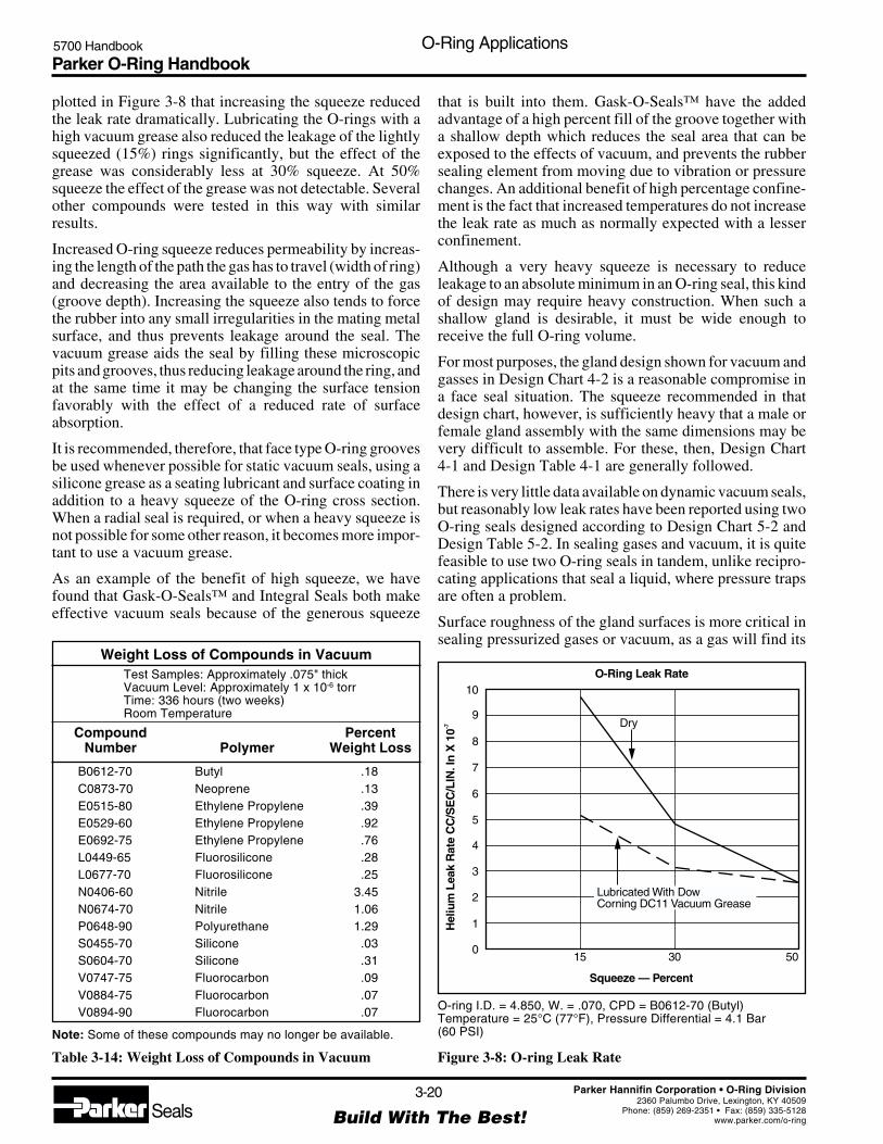
Parker O-Ring Handbook5700 Handbook O-Ring Applications
3-20
Build With The Best!SealsParker Hannifin Corporation • O-Ring Division
2360 Palumbo Drive, Lexington, KY 40509Phone: (859) 269-2351 • Fax: (859) 335-5128
www.parker.com/o-ring
O-ring I.D. = 4.850, W. = .070, CPD = B0612-70 (Butyl)Temperature = 25°C (77°F), Pressure Differential = 4.1 Bar(60 PSI)
Figure 3-8: O-ring Leak Rate
Squeeze — Percent
Hel
ium
Lea
k R
ate
CC
/SE
C/L
IN.I
n X
10-7
15
10
Dry9
8
7
6
5
4
3
2
1
030 50
O-Ring Leak Rate
Lubricated With DowCorning DC11 Vacuum Grease
plotted in Figure 3-8 that increasing the squeeze reducedthe leak rate dramatically. Lubricating the O-rings with ahigh vacuum grease also reduced the leakage of the lightlysqueezed (15%) rings significantly, but the effect of thegrease was considerably less at 30% squeeze. At 50%squeeze the effect of the grease was not detectable. Severalother compounds were tested in this way with similarresults.
Increased O-ring squeeze reduces permeability by increas-ing the length of the path the gas has to travel (width of ring)and decreasing the area available to the entry of the gas(groove depth). Increasing the squeeze also tends to forcethe rubber into any small irregularities in the mating metalsurface, and thus prevents leakage around the seal. Thevacuum grease aids the seal by filling these microscopicpits and grooves, thus reducing leakage around the ring, andat the same time it may be changing the surface tensionfavorably with the effect of a reduced rate of surfaceabsorption.
It is recommended, therefore, that face type O-ring groovesbe used whenever possible for static vacuum seals, using asilicone grease as a seating lubricant and surface coating inaddition to a heavy squeeze of the O-ring cross section.When a radial seal is required, or when a heavy squeeze isnot possible for some other reason, it becomes more impor-tant to use a vacuum grease.
As an example of the benefit of high squeeze, we havefound that Gask-O-Seals™ and Integral Seals both makeeffective vacuum seals because of the generous squeeze
that is built into them. Gask-O-Seals™ have the addedadvantage of a high percent fill of the groove together witha shallow depth which reduces the seal area that can beexposed to the effects of vacuum, and prevents the rubbersealing element from moving due to vibration or pressurechanges. An additional benefit of high percentage confine-ment is the fact that increased temperatures do not increasethe leak rate as much as normally expected with a lesserconfinement.
Although a very heavy squeeze is necessary to reduceleakage to an absolute minimum in an O-ring seal, this kindof design may require heavy construction. When such ashallow gland is desirable, it must be wide enough toreceive the full O-ring volume.
For most purposes, the gland design shown for vacuum andgasses in Design Chart 4-2 is a reasonable compromise ina face seal situation. The squeeze recommended in thatdesign chart, however, is sufficiently heavy that a male orfemale gland assembly with the same dimensions may bevery difficult to assemble. For these, then, Design Chart4-1 and Design Table 4-1 are generally followed.
There is very little data available on dynamic vacuum seals,but reasonably low leak rates have been reported using twoO-ring seals designed according to Design Chart 5-2 andDesign Table 5-2. In sealing gases and vacuum, it is quitefeasible to use two O-ring seals in tandem, unlike recipro-cating applications that seal a liquid, where pressure trapsare often a problem.
Surface roughness of the gland surfaces is more critical insealing pressurized gases or vacuum, as a gas will find its
Weight Loss of Compounds in VacuumTest Samples: Approximately .075" thickVacuum Level: Approximately 1 x 10⁻⁶ torrTime: 336 hours (two weeks)Room Temperature
Compound PercentNumber Polymer Weight Loss
B0612-70 Butyl .18C0873-70 Neoprene .13E0515-80 Ethylene Propylene .39E0529-60 Ethylene Propylene .92E0692-75 Ethylene Propylene .76L0449-65 Fluorosilicone .28L0677-70 Fluorosilicone .25N0406-60 Nitrile 3.45N0674-70 Nitrile 1.06P0648-90 Polyurethane 1.29S0455-70 Silicone .03S0604-70 Silicone .31V0747-75 Fluorocarbon .09V0884-75 Fluorocarbon .07V0894-90 Fluorocarbon .07
Note: Some of these compounds may no longer be available.
Table 3-14: Weight Loss of Compounds in Vacuum

Parker O-Ring Handbook5700 Handbook O-Ring Applications
3-21
Build With The Best!SealsParker Hannifin Corporation • O-Ring Division
2360 Palumbo Drive, Lexington, KY 40509Phone: (859) 269-2351 • Fax: (859) 335-5128
www.parker.com/o-ring
• Temperature compatibility• Low weight loss in vacuum
For more detailed information see Rate of gas leakage.
3.12 Gases-Permeability
All elastomers are permeable to some extent, allowing air,other gases under pressure or volatile liquids to penetrateinto the seal material and gradually escape on the lowpressure side.
The permeability rate of various gases through differentrubber materials varies in an unpredictable way. In fact, thepermeability of a given base polymer will vary according tothe proportions of the copolymer, among other things.Figure 3-10 shows this very clearly for one class of butadi-ene-acrylonitrile copolymers.
The permeability also varies with temperature, and thoughthe rate increases with increasing temperature, there is noeasily defined relationship between these two variables.Table 3-19 (found at the end of this section) lists somepermeability rates at various temperatures that may behelpful in approximating leak rates through O-ring seals.
3.12.1 Leak Rate Approximation
The leak rate of a gas through an O-ring seal may beroughly approximated when the permeability of the gasthrough the particular elastomer is known for the tempera-ture at which the seal must function. The following formulais useful for this approximation:
L = 0.7 F D P Q (1-S)²where
L = Approximate leak rate of the seal, std. cc/sec.F = Permeability rate of the gas through the elastomer
at the anticipated operating temperature, std. cccm/cm² sec bar (Many of these permeability ratesare listed in Table 3-19, found at the end of thissection)
way through extremely minute passages. Therefore, sur-faces against which an O-ring must seal should have asurface roughness value smoother than usual. Surfacefinishes of 16 RMS are quite common, but 32 RMS finisheshave been used successfully also.
3.11.3 Vacuum Leak Rate
To determine approximate leak rate for a vacuum seal, usethe “Leak Rate Approximation” method in the section onGases. Note that where the external pressure is one atmo-sphere, the pressure differential across the seal (P) is 14.7PSI.
Many parameters should be observed to seal a vacuum. Ingeneral apply the following recommendations:
• Select correct O-ring compound;• The surfaces to be sealed and the gland must have a
significantly better surface finish than for “normal”seals Table 3-15;
• The O-ring should fill the gland (nearly 100%, Figure3-9). Larger contact areas are thereby created and thediffusion rate through the elastomer is slowed;
• To increase efficiency, two seals can be fitted in tandemin separate glands;
• The total leakage rate is reduced using a suitablevacuum grease.
Requirements for the O-ring compound are:• Low gas permeation rate• Good, i.e. low compression set• Compatibility of medium
Figure 3-9: Vacuum O-ring Gland
Surface Finish of Vacuum Gland
Surface Roughness of Vacuum GlandLoad Area tp > 50%
A Contact Area B Gland Flanks
Ra Rmax Ra Rmax
Vacuum 0.8 3.2 1.6 6.3
to 10-8 Torr 0.4 1.6 1.6 6.3
to 10-11 Torr 0.10 0.40 1.6 6.3
Table 3-15: Surface Finish of Vacuum Gland(See also Figure 3-9)
Vacuum
A
A
B
Atm
osph
ere
B
Figure 3-10: Effect of Acrylonitrile Content onPermeability of Butadiene-Acrylonitrile Copolymers at25°C (77°F) from "Gas Permeability of Hycar Polymers"by B. F. Goodrich Company
Acrylonitrile Content (%)
CO 2 H2
He
O2
N2
Per
mea
bilit
y R
ate
–C
C/S
EC
/ATM
10
10-7
10-8
10-9
10-6
20 30 40
Effects of Acrylonitrile Content on Permeabilityof Butadiene-Acrylonitrile Copolymers
at 25°C (77°F)
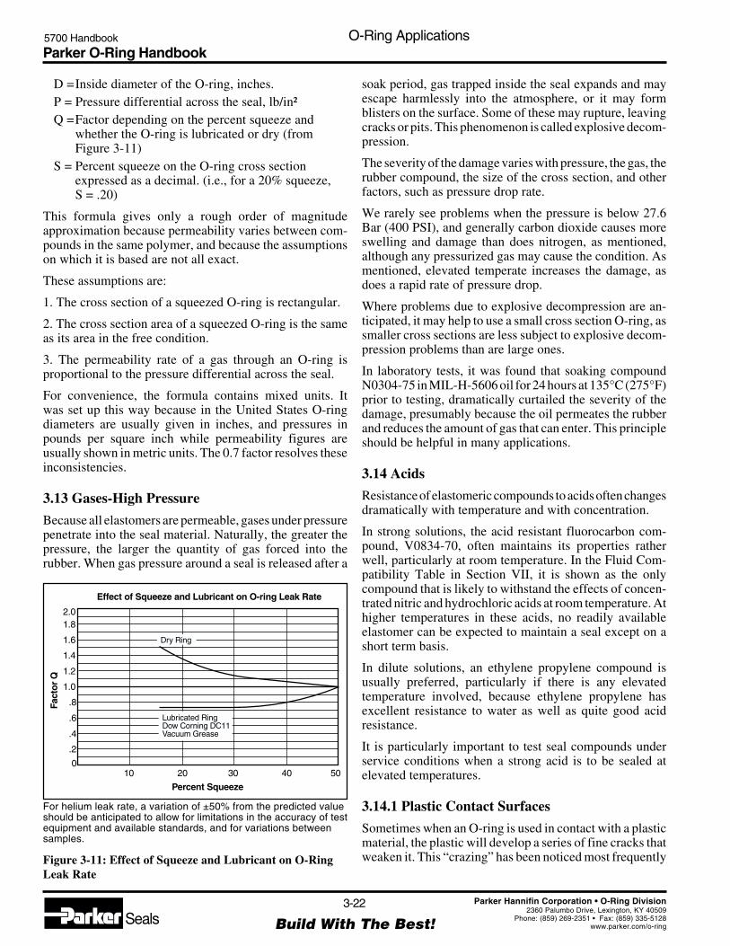
Parker O-Ring Handbook5700 Handbook O-Ring Applications
3-22
Build With The Best!SealsParker Hannifin Corporation • O-Ring Division
2360 Palumbo Drive, Lexington, KY 40509Phone: (859) 269-2351 • Fax: (859) 335-5128
www.parker.com/o-ring
For helium leak rate, a variation of ±50% from the predicted valueshould be anticipated to allow for limitations in the accuracy of testequipment and available standards, and for variations betweensamples.
Figure 3-11: Effect of Squeeze and Lubricant on O-RingLeak Rate
Effect of Squeeze and Lubricant on O-ring Leak Rate
Percent Squeeze
Fact
or Q
10
2.01.8
1.6
1.4
1.2
1.0
.8
.6
.4
.2
020 30 40 50
Dry Ring
Lubricated RingDow Corning DC11Vacuum Grease
D =Inside diameter of the O-ring, inches.P = Pressure differential across the seal, lb/in²Q =Factor depending on the percent squeeze and
whether the O-ring is lubricated or dry (fromFigure 3-11)
S = Percent squeeze on the O-ring cross sectionexpressed as a decimal. (i.e., for a 20% squeeze,S = .20)
This formula gives only a rough order of magnitudeapproximation because permeability varies between com-pounds in the same polymer, and because the assumptionson which it is based are not all exact.
These assumptions are:
1. The cross section of a squeezed O-ring is rectangular.
2. The cross section area of a squeezed O-ring is the sameas its area in the free condition.
3. The permeability rate of a gas through an O-ring isproportional to the pressure differential across the seal.
For convenience, the formula contains mixed units. Itwas set up this way because in the United States O-ringdiameters are usually given in inches, and pressures inpounds per square inch while permeability figures areusually shown in metric units. The 0.7 factor resolves theseinconsistencies.
3.13 Gases-High Pressure
Because all elastomers are permeable, gases under pressurepenetrate into the seal material. Naturally, the greater thepressure, the larger the quantity of gas forced into therubber. When gas pressure around a seal is released after a
soak period, gas trapped inside the seal expands and mayescape harmlessly into the atmosphere, or it may formblisters on the surface. Some of these may rupture, leavingcracks or pits. This phenomenon is called explosive decom-pression.
The severity of the damage varies with pressure, the gas, therubber compound, the size of the cross section, and otherfactors, such as pressure drop rate.
We rarely see problems when the pressure is below 27.6Bar (400 PSI), and generally carbon dioxide causes moreswelling and damage than does nitrogen, as mentioned,although any pressurized gas may cause the condition. Asmentioned, elevated temperate increases the damage, asdoes a rapid rate of pressure drop.
Where problems due to explosive decompression are an-ticipated, it may help to use a small cross section O-ring, assmaller cross sections are less subject to explosive decom-pression problems than are large ones.
In laboratory tests, it was found that soaking compoundN0304-75 in MIL-H-5606 oil for 24 hours at 135°C (275°F)prior to testing, dramatically curtailed the severity of thedamage, presumably because the oil permeates the rubberand reduces the amount of gas that can enter. This principleshould be helpful in many applications.
3.14 Acids
Resistance of elastomeric compounds to acids often changesdramatically with temperature and with concentration.
In strong solutions, the acid resistant fluorocarbon com-pound, V0834-70, often maintains its properties ratherwell, particularly at room temperature. In the Fluid Com-patibility Table in Section VII, it is shown as the onlycompound that is likely to withstand the effects of concen-trated nitric and hydrochloric acids at room temperature. Athigher temperatures in these acids, no readily availableelastomer can be expected to maintain a seal except on ashort term basis.
In dilute solutions, an ethylene propylene compound isusually preferred, particularly if there is any elevatedtemperature involved, because ethylene propylene hasexcellent resistance to water as well as quite good acidresistance.
It is particularly important to test seal compounds underservice conditions when a strong acid is to be sealed atelevated temperatures.
3.14.1 Plastic Contact Surfaces
Sometimes when an O-ring is used in contact with a plasticmaterial, the plastic will develop a series of fine cracks thatweaken it. This “crazing” has been noticed most frequently
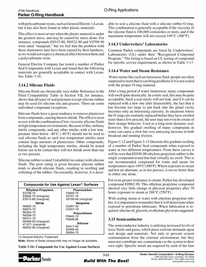
Parker O-Ring Handbook5700 Handbook O-Ring Applications
3-23
Build With The Best!SealsParker Hannifin Corporation • O-Ring Division
2360 Palumbo Drive, Lexington, KY 40509Phone: (859) 269-2351 • Fax: (859) 335-5128
www.parker.com/o-ring
with polycarbonate resins, such as General Electric’s Lexan,but it has also been found in other plastic materials.
This effect is most severe when the plastic material is underthe greatest stress, and may be caused by stress alone. Forinstance, compounds E0515-80, N0522-90 and V0709-90were rated “marginal,” but we feel that the problem withthese elastomers may have been caused by their hardness,as we would not expect a chemical effect between them anda polycarbonate resin.
General Electric Company has tested a number of ParkerSeal Compounds with Lexan and found that the followingmaterials are generally acceptable in contact with Lexan.See Table 3-16.
3.14.2 Silicone Fluids
Silicone fluids are chemically very stable. Reference to theFluid Compatibility Table in Section VII, for instance,shows that all types of seal polymers except silicone rubbermay be used for silicone oils and greases. There are someindividual compound exceptions.
Silicone fluids have a great tendency to remove plasticizerfrom compounds, causing them to shrink. The effect is mostsevere with the combination of low viscosity silicone fluidsin high temperature environments. Because of this, militarynitrile compounds, and any other nitriles with a low tem-perature limit below -40°C (-40°F) should not be used toseal silicone fluids as such low temperature nitriles mustcontain large amounts of plasticizers. Other compounds,including the high temperature nitriles, should be testedbefore use to be certain they will not shrink more than oneor two percent.
Silicone rubber is rated 3 (doubtful) in contact with siliconefluids. The poor rating is given because silicone rubbertends to absorb silicone fluids, resulting in swelling andsoftening of the rubber. Occasionally, however, it is desir-
able to seal a silicone fluid with a silicone rubber O-ring.This combination is generally acceptable if the viscosity ofthe silicone fluid is 100,000 centistokes or more, and if themaximum temperature will not exceed 149°C (300°F).
3.14.3 Underwriters’ Laboratories
Common Parker compounds are listed by Underwriters’Laboratories (UL) under their “Recognized CompoundProgram.” The listing is based on UL testing of compoundfor specific service requirements as shown in Table 3-17.
3.14.4 Water and Steam Resistance
Water seems like such an innocuous fluid; people are oftensurprised to learn that it can bring problems if it is not sealedwith the proper O-ring material.
After a long period of water immersion, many compoundswill swell quite drastically. In a static seal, this may be quiteacceptable. Such a seal surely will not leak, and if it can bereplaced with a new one after disassembly, the fact that ithas become too large to put back into the gland cavitybecomes only an interesting curiosity. In situations wherethe O-rings are routinely replaced before they have swelledmore than a few percent, the user may not even be aware oftheir strange behavior. Used as a long-term dynamic seal,however, this gradual swelling of many compounds inwater can cause a slow but very annoying increase in bothbreakout and running friction.
Figure 3-12 and Figure 3-13 illustrate this gradual swellingof a number of Parker Seal compounds when exposed towater at two different temperatures. From these curves itwill be seen that E0540-80 ethylene propylene rubber is thesingle compound tested that had virtually no swell. This isour recommended compound for water and steam fortemperatures up to 149°C (300°F). Where exposure to steamand hot air alternate, as in tire presses, it serves better thanin either one alone.
For even greater resistance to steam, Parker has developedcompound E0962-90. This ethylene propylene compoundshowed very little change in physical properties after 70hours exposure to steam at 288°C (550°F).
With sealing steam or water with ethylene propylene rub-ber, it is important to remember that it will deteriorate whenexposed to petroleum lubricants. When lubrication is re-quired, silicone oil, glycerin, or ethylene glycol are suggested.
3.15 Semiconductor
The semiconductor industry is utilizing increased levels oftoxic fluids and gases, which place extreme demands uponseal design and materials. Not only to prevent systemcontamination from the external environment, but theymust not contribute any contaminates to the system in theirown right. Specific needs are required by each of the four
Compounds for Use Against Lexan(1) Surfaces
Ethylene PropyleneE0798-70E0692-75 (marginal)E0515-80 (marginal)
NitrileN0602-70N0674-70N0304-75N0508-75N0741-75N0506-65 (marginal)47-071 (marginal)N0552-90 (marginal)
(1) General Electric TrademarkNote: Some of these compounds may no longer be available.
Table 3-16: Compounds for Use Against Lexan Surfaces
FluorocarbonV0680-70V0747-75V0709-90 (marginal)
NeopreneC0267-50C0557-70
PolyurethaneP0642-70P0648-90
SiliconeS0317-60S0469-40S0604-70

Parker O-Ring Handbook5700 Handbook O-Ring Applications
3-24
Build With The Best!SealsParker Hannifin Corporation • O-Ring Division
2360 Palumbo Drive, Lexington, KY 40509Phone: (859) 269-2351 • Fax: (859) 335-5128
www.parker.com/o-ring
Figure 3-12: Water and Steam Resistance at RoomTemperature
Figure 3-13: Water and Steam Resistance at 70°C (158°F)
Room Temperature
C0557-70
N0219-70
Time —Years
30
25
20
15
10
5
0
1 2 3
Per
cent
Sw
ell
N0103-70
N0406-60
N0398-70
E0540-80
70°C (158° F)
Time —Years
300N0406-60
N0398-70
E0540-80
N0103-70
250
200
150
100
50
0
Per
cent
Sw
ell
C0557-70
primary environments employed by the semiconductorindustry:
• Gases & Vacuum • Thermal• Plasma • Wet Processing
Working conditions:
Temperatures: up to 300°C (572°F)Pressures: vacuum to 10-9
Contact our Inside Sales Engineering Department regard-ing Semiconductor sealing applications.
3.16 inPHorm Seal Design and Material SelectionSoftware
Parker recommends utilizing inPHorm to guide the userthrough the design and selection of an O-ring and corre-sponding seal gland. inPHorm not only addresses standardo-ring sizes, but will allow the user to custom design O-ringglands and seals specifically for their application. To obtaininPHorm contact the O-Ring Division, Parker ProductInformation 1-800-C-PARKER or your nearest authorizedParker O-Ring distributor. If inPHorm is not readily avail-able manual calculations can be performed using thefollowing guidelines.
Underwriters’ Laboratories
Service Compound
Fire Extinguishing Agents X X
Gasoline X X X X X X X X X X X
Gasoline/Alcohol Blends* X X X X X X X X X X
Naptha or Kerosene X X X X X X X X X X X X X
MFG or Natural Gas X X X X X X X X
Diesel Fuel, Fuel Oil, Lubricating Oil X X X X X X X X X X X X X
Heated Fuel Oil X X X
Anhydrous Ammonia X
LP-Gas X X X X X X X X
Suitable for use in UL1081 X
Suitable for use in UL262 applications X
Dry Chemical, Carbon Dioxide, Water X X
*Contact factory for specific ratios of alcohol (methyl and/or ethyl) and gasoline
Table 3-17: Underwriters’ Laboratories – JMLU2 – Gaskets and Seals
L11
20-7
0
N02
99-5
0
N04
97-7
0
N06
74-7
0
N07
57-7
0
N14
99-7
0
N15
00-7
5
V07
47-7
5
V08
84-7
5
V11
63-7
5
V12
26-7
5
V12
37-6
5
V12
62-6
5
V12
63-7
5
V12
64-9
0
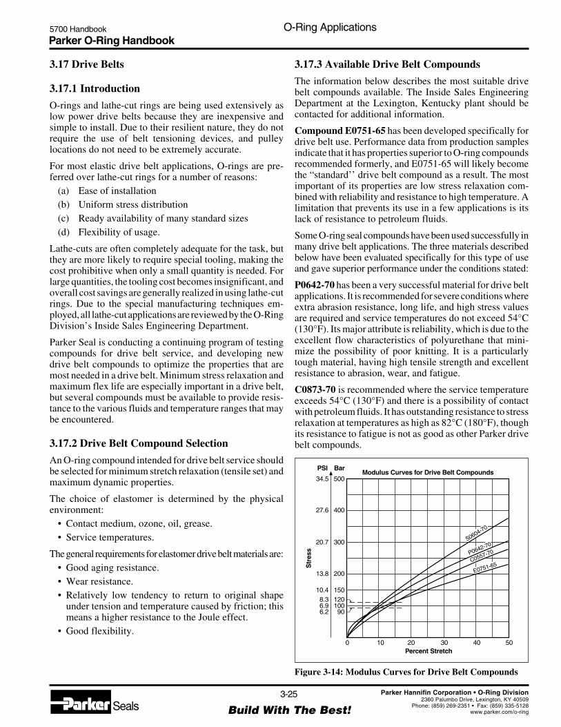
Parker O-Ring Handbook5700 Handbook O-Ring Applications
3-25
Build With The Best!SealsParker Hannifin Corporation • O-Ring Division
2360 Palumbo Drive, Lexington, KY 40509Phone: (859) 269-2351 • Fax: (859) 335-5128
www.parker.com/o-ring
3.17 Drive Belts
3.17.1 Introduction
O-rings and lathe-cut rings are being used extensively aslow power drive belts because they are inexpensive andsimple to install. Due to their resilient nature, they do notrequire the use of belt tensioning devices, and pulleylocations do not need to be extremely accurate.
For most elastic drive belt applications, O-rings are pre-ferred over lathe-cut rings for a number of reasons:
(a) Ease of installation(b) Uniform stress distribution(c) Ready availability of many standard sizes(d) Flexibility of usage.
Lathe-cuts are often completely adequate for the task, butthey are more likely to require special tooling, making thecost prohibitive when only a small quantity is needed. Forlarge quantities, the tooling cost becomes insignificant, andoverall cost savings are generally realized in using lathe-cutrings. Due to the special manufacturing techniques em-ployed, all lathe-cut applications are reviewed by the O-RingDivision’s Inside Sales Engineering Department.
Parker Seal is conducting a continuing program of testingcompounds for drive belt service, and developing newdrive belt compounds to optimize the properties that aremost needed in a drive belt. Minimum stress relaxation andmaximum flex life are especially important in a drive belt,but several compounds must be available to provide resis-tance to the various fluids and temperature ranges that maybe encountered.
3.17.2 Drive Belt Compound Selection
An O-ring compound intended for drive belt service shouldbe selected for minimum stretch relaxation (tensile set) andmaximum dynamic properties.
The choice of elastomer is determined by the physicalenvironment:
• Contact medium, ozone, oil, grease.• Service temperatures.
The general requirements for elastomer drive belt materials are:• Good aging resistance.• Wear resistance.• Relatively low tendency to return to original shape
under tension and temperature caused by friction; thismeans a higher resistance to the Joule effect.
• Good flexibility.
3.17.3 Available Drive Belt Compounds
The information below describes the most suitable drivebelt compounds available. The Inside Sales EngineeringDepartment at the Lexington, Kentucky plant should becontacted for additional information.
Compound E0751-65 has been developed specifically fordrive belt use. Performance data from production samplesindicate that it has properties superior to O-ring compoundsrecommended formerly, and E0751-65 will likely becomethe “standard’’ drive belt compound as a result. The mostimportant of its properties are low stress relaxation com-bined with reliability and resistance to high temperature. Alimitation that prevents its use in a few applications is itslack of resistance to petroleum fluids.
Some O-ring seal compounds have been used successfully inmany drive belt applications. The three materials describedbelow have been evaluated specifically for this type of useand gave superior performance under the conditions stated:
P0642-70 has been a very successful material for drive beltapplications. It is recommended for severe conditions whereextra abrasion resistance, long life, and high stress valuesare required and service temperatures do not exceed 54°C(130°F). Its major attribute is reliability, which is due to theexcellent flow characteristics of polyurethane that mini-mize the possibility of poor knitting. It is a particularlytough material, having high tensile strength and excellentresistance to abrasion, wear, and fatigue.
C0873-70 is recommended where the service temperatureexceeds 54°C (130°F) and there is a possibility of contactwith petroleum fluids. It has outstanding resistance to stressrelaxation at temperatures as high as 82°C (180°F), thoughits resistance to fatigue is not as good as other Parker drivebelt compounds.
Percent Stretch
Modulus Curves for Drive Belt CompoundsBar
400
500
300
200
150
100120
90
PSI
27.6
34.5
20.7
13.8
10.4
6.98.3
6.2
0 10 20 30 40
S0604-70
P0642-70
C0557-70
E0751-65
50
Figure 3-14: Modulus Curves for Drive Belt Compounds

Parker O-Ring Handbook5700 Handbook O-Ring Applications
3-26
Build With The Best!SealsParker Hannifin Corporation • O-Ring Division
2360 Palumbo Drive, Lexington, KY 40509Phone: (859) 269-2351 • Fax: (859) 335-5128
www.parker.com/o-ring
Parker Seal Elastic Drive Belt Compound Data(1)
Compound Number DBA(5) E0751-65 DBA(5) P0642-70 DBA(5) C0557-70 DBA(5) S0604-70Specific Gravity, G 1.13 1.29 1.47 1.43
Dynamic Stress Relaxation(2)
Initial Stress, 120 PSI 13% 19% 14% 21%
Temp °C (°F)Static Stress Relaxation(3) 24 (75) 14% 21% 14% 2%Initial Stress, 120 PSI 66 (150) 18% 29% 19% 5%
82 (180) 20% 36% 22% 2%
Flex Life Rating Good Excellent Acceptable Excellent
Maximum Temperature, °C (°F) 82 (180) 54 (130) 82 (180) 149 (300)
Hardness, Shore A, Durometer 65±5 70±5 70±5 70±5Tensile Strength, Bar (PSI) 135.9 (1970) 302.2 (4380) 138.0 (2000) 62.1 (900)Elongation, % 385 535 250 160Modulus @ 100%, Elongation, Bar (PSI) 30.4 (440) 29 (420) 38.0 (550) 41.1 (600)
Resistance to:(4)
Petroleum Fluids Poor Excellent Good PoorSilicone Fluids Excellent Excellent Excellent PoorWater Excellent Fair Good GoodOzone Excellent Excellent Good ExcellentAbrasion Good Excellent Good Poor
(1)All values shown are typical. Do not use for specification limits. Specimens: 2-153 O-rings.(2)After three days dynamic testing at room temperature Motor pulley pitch diameter: .611", speed: 1740 rpm. Cast iron driven pulley
pitch diameter: 2.623". Duty cycle 3 minutes on, 15 seconds off. Load: inertia of cast iron pulley.(3)After 48 hours static testing at temperature indicated. Two ½" diameter pulleys.(4)For information on resistance of these materials to other fluids, see Fluid Compatibility Table in Section VII.(5)When ordering parts for drive belt applications, the letters “DBA” precede the part number. Example: DBAS0604-70 2-250.
Table 3-18: Parker Seal Elastic Drive Belt Compound Data
S0604-70 is the compound generally selected for hightemperature use or for applications where the black color ofthe other drive belt compounds is not permissible. Being asilicone, however, it does not have the tensile strength orresistance to wear and abrasion of the other compounds.The user, therefore, should not sacrifice these importantproperties by specifying an unrealistically high temperatureto provide a “safety factor”. Usually some excess tempera-ture can be tolerated if the exposure time is of short durationand is repeated only a few times during the life of the drivebelt. It should be remembered that the physical propertiesof any compound will be poorer at elevated temperature.
Table 3-18 compares the important properties of theserubber materials. Specific gravity and stress relaxation arelisted first because these data are needed in drive beltdesign. When drive belts may contact fluids not listed inTable 3-18, refer to the Fluid Compatibility Tables inSection VII. In any case, contact of elastomeric drive beltswith any liquid must be kept to an absolute minimum.Almost any liquid on the belt will reduce friction, causingslippage. Since contact with fluids is seldom encountered indrive belt practice, this becomes a minor consideration.
3.18 Applications Summary
In the foregoing discussions on special applications, thereare necessarily many references to problems and failures,but the object of pointing out possible pitfalls is to indicateto the designer the steps he can take to avoid them. Theobject of this whole reference manual, then, is the verypositive one of showing how to produce reliable, economi-cal, effective O-ring seals for a diversity of uses.
An important factor in most O-ring seals is the rubbercompound from which it is made. For the special applica-tions presented in this chapter, many specific compoundrecommendations are included. Parker Compound recom-mendations based on fluid type alone will be found in theFluid Compatibility Tables in Section VII.
It is an excellent practice, after selecting one or more likelymaterials, to study those portions of the Elastomers sectionthat apply to that material. Background information isgiven there that will give the designer a better understand-ing of the general properties of each of the major polymers,and help him select wisely when a choice or compromisemust be made. The explanations of physical properties andhow they are tested are also necessary for an adequateunderstanding of rubber materials and their behaviour indifferent operating environments.

Parker O-Ring Handbook5700 Handbook O-Ring Applications
3-27
Build With The Best!SealsParker Hannifin Corporation • O-Ring Division
2360 Palumbo Drive, Lexington, KY 40509Phone: (859) 269-2351 • Fax: (859) 335-5128
www.parker.com/o-ring
1 Std cc cm/cm2 sec. bar2 “I” denotes information from “Permeability Data for Aerospace Applications” funded by NASA and prepared by IIT Research Institute, March 1968.
“A” denotes information from Atomics International Division, Energy Systems Group, Rockwell International publication AI-AEC-13145,“Design Guide for Reactor Cover Gas Elastomer Seals” March 7, 1975, and addendum, report ESC-DOE-13245, September 30, 1978.
“DC” denotes information from Dow Corning Bulletin 17-158, October 1972.“P” denotes information from Parker Seal tests.
3 “NR” Temperature not reported.4 Trademark E.I. Du Pont de Nemours & Co.
Table 3-19: Gas Permeability Rates
Acetone Silicone 25 77 14,850 I
Acetylene Butyl 25 77 1.26 IAcetylene Butyl 50 122 5.74 IAcetylene Natural 25 77 74.5 IAcetylene Natural 50 122 192 IAcetylene Nitrile 25 77 18.7 IAcetylene Nitrile 50 122 67.4 I
Air Butyl Room 0.2 DCAir Butyl 200 392 100 DCAir Fluorosilicone Room 48.4 DCAir Natural Room 6.7 DCAir Natural 200 392 262 DCAir Silicone Room 18.0 to 25.6 DCAir Silicone 200 392 74 DCAir Polyurethane Room 0.5 DC
Ammonia Silicone 25 77 4396 I
Argon Butyl (B0318-70) 35 95 1.19 AArgon Butyl (B0318-70) 82 180 9.04 AArgon Butyl (B0318-70) 124 255 36.1 AArgon Ethylene Propylene 38 100 11.3 to 22.9 AArgon Ethylene Propylene (E0529-65) 40 104 22.9 AArgon Ethylene Propylene (E0692-75) 38 100 15.58 AArgon Ethylene Propylene 93 200 57.0 to 108.7 AArgon Ethylene Propylene (E0529-65) 94 202 105 AArgon Ethylene Propylene (E0692-75) 93 199 77 AArgon Ethylene Propylene 149 300 170 to 375 AArgon Ethylene Propylene (E0529-65) 155 311 375 AArgon Ethylene Propylene (E0692-75) 149 300 280 AArgon Fluorocarbon-Viton4 93 200 31 AArgon Natural 25 77 17.2 IArgon Neoprene 36 97 0.67 IArgon Neoprene 38 100 18 AArgon Neoprene 52 126 1.42 IArgon Neoprene 86 187 6.46 IArgon Nitrile 38 100 1.60 to 3.88 AArgon Nitrile (N0741-75) 39 103 2.06 AArgon Nitrile 79 175 6.39 to 16.7 AArgon Nitrile (N0741-75) 80 176 7.36 AArgon Nitrile 121 250 13.7 to 62.3 AArgon Nitrile (N0741-75) 118 245 34 AArgon Polyacrylate (A0607-70) 38 100 8.28 AArgon Polyacrylate (A0607-70) 91 195 40.66 AArgon Polyacrylate (A0607-70) 153 307 327 AArgon Polyurethane (P0642-70) 39 103 1.5 AArgon Polyurethane (P0648-90) 39 102 0.99 AArgon Polyurethane (P0642-70) 66 151 5.45 AArgon Polyurethane (P0648-90) 67 152 4.07 AArgon Polyurethane (P0642-70) 94 202 20.8 AArgon Polyurethane (P0648-90) 94 201 7.3 A
Gas Permeability Rates
Gas or Temperature Permeability (1)
Liquid Elastomer °C °F x 10-8 Source (2)
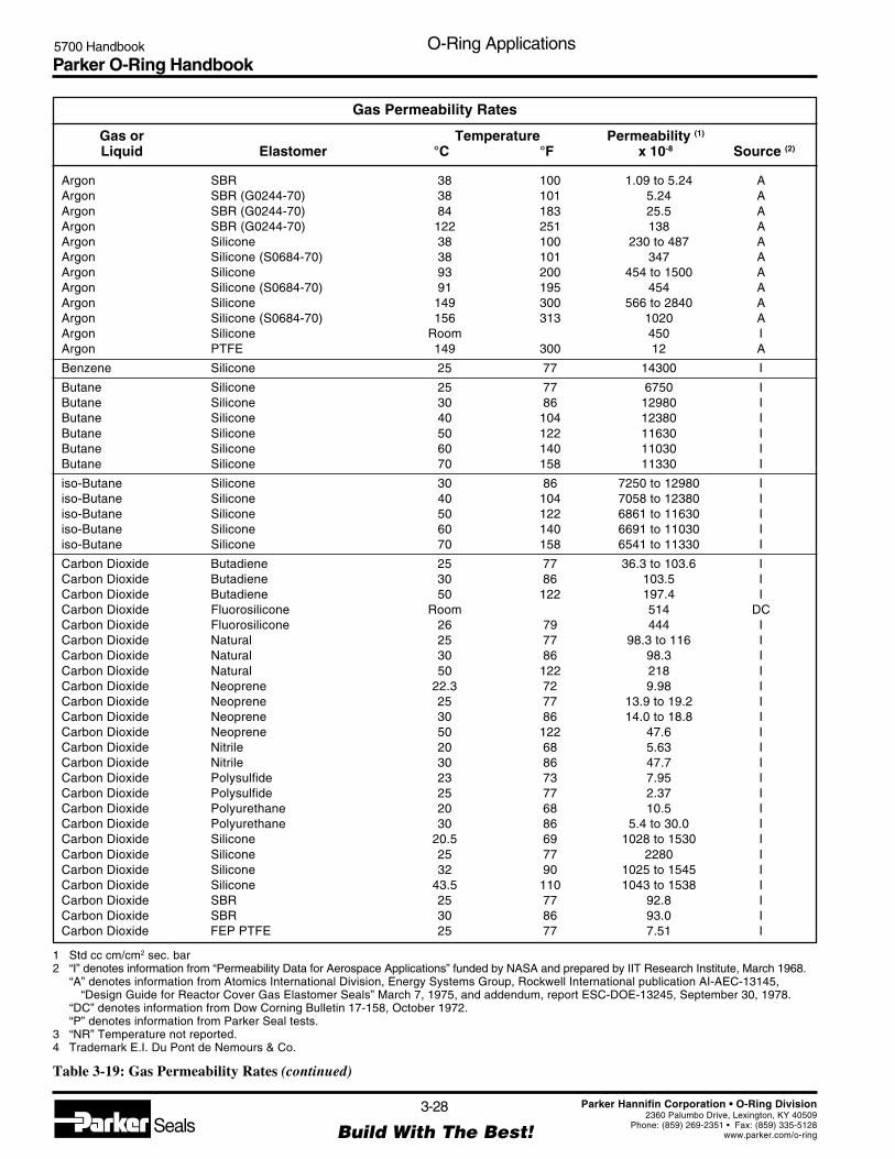
Parker O-Ring Handbook5700 Handbook O-Ring Applications
3-28
Build With The Best!SealsParker Hannifin Corporation • O-Ring Division
2360 Palumbo Drive, Lexington, KY 40509Phone: (859) 269-2351 • Fax: (859) 335-5128
www.parker.com/o-ring
1 Std cc cm/cm2 sec. bar2 “I” denotes information from “Permeability Data for Aerospace Applications” funded by NASA and prepared by IIT Research Institute, March 1968.
“A” denotes information from Atomics International Division, Energy Systems Group, Rockwell International publication AI-AEC-13145,“Design Guide for Reactor Cover Gas Elastomer Seals” March 7, 1975, and addendum, report ESC-DOE-13245, September 30, 1978.
“DC” denotes information from Dow Corning Bulletin 17-158, October 1972.“P” denotes information from Parker Seal tests.
3 “NR” Temperature not reported.4 Trademark E.I. Du Pont de Nemours & Co.
Table 3-19: Gas Permeability Rates (continued)
Gas Permeability Rates
Gas or Temperature Permeability (1)
Liquid Elastomer °C °F x 10-8 Source (2)
Argon SBR 38 100 1.09 to 5.24 AArgon SBR (G0244-70) 38 101 5.24 AArgon SBR (G0244-70) 84 183 25.5 AArgon SBR (G0244-70) 122 251 138 AArgon Silicone 38 100 230 to 487 AArgon Silicone (S0684-70) 38 101 347 AArgon Silicone 93 200 454 to 1500 AArgon Silicone (S0684-70) 91 195 454 AArgon Silicone 149 300 566 to 2840 AArgon Silicone (S0684-70) 156 313 1020 AArgon Silicone Room 450 IArgon PTFE 149 300 12 A
Benzene Silicone 25 77 14300 I
Butane Silicone 25 77 6750 IButane Silicone 30 86 12980 IButane Silicone 40 104 12380 IButane Silicone 50 122 11630 IButane Silicone 60 140 11030 IButane Silicone 70 158 11330 I
iso-Butane Silicone 30 86 7250 to 12980 Iiso-Butane Silicone 40 104 7058 to 12380 Iiso-Butane Silicone 50 122 6861 to 11630 Iiso-Butane Silicone 60 140 6691 to 11030 Iiso-Butane Silicone 70 158 6541 to 11330 I
Carbon Dioxide Butadiene 25 77 36.3 to 103.6 ICarbon Dioxide Butadiene 30 86 103.5 ICarbon Dioxide Butadiene 50 122 197.4 ICarbon Dioxide Fluorosilicone Room 514 DCCarbon Dioxide Fluorosilicone 26 79 444 ICarbon Dioxide Natural 25 77 98.3 to 116 ICarbon Dioxide Natural 30 86 98.3 ICarbon Dioxide Natural 50 122 218 ICarbon Dioxide Neoprene 22.3 72 9.98 ICarbon Dioxide Neoprene 25 77 13.9 to 19.2 ICarbon Dioxide Neoprene 30 86 14.0 to 18.8 ICarbon Dioxide Neoprene 50 122 47.6 ICarbon Dioxide Nitrile 20 68 5.63 ICarbon Dioxide Nitrile 30 86 47.7 ICarbon Dioxide Polysulfide 23 73 7.95 ICarbon Dioxide Polysulfide 25 77 2.37 ICarbon Dioxide Polyurethane 20 68 10.5 ICarbon Dioxide Polyurethane 30 86 5.4 to 30.0 ICarbon Dioxide Silicone 20.5 69 1028 to 1530 ICarbon Dioxide Silicone 25 77 2280 ICarbon Dioxide Silicone 32 90 1025 to 1545 ICarbon Dioxide Silicone 43.5 110 1043 to 1538 ICarbon Dioxide SBR 25 77 92.8 ICarbon Dioxide SBR 30 86 93.0 ICarbon Dioxide FEP PTFE 25 77 7.51 I

Parker O-Ring Handbook5700 Handbook O-Ring Applications
3-29
Build With The Best!SealsParker Hannifin Corporation • O-Ring Division
2360 Palumbo Drive, Lexington, KY 40509Phone: (859) 269-2351 • Fax: (859) 335-5128
www.parker.com/o-ring
1 Std cc cm/cm2 sec. bar2 “I” denotes information from “Permeability Data for Aerospace Applications” funded by NASA and prepared by IIT Research Institute, March 1968.
“A” denotes information from Atomics International Division, Energy Systems Group, Rockwell International publication AI-AEC-13145,“Design Guide for Reactor Cover Gas Elastomer Seals” March 7, 1975, and addendum, report ESC-DOE-13245, September 30, 1978.
“DC” denotes information from Dow Corning Bulletin 17-158, October 1972.“P” denotes information from Parker Seal tests.
3 “NR” Temperature not reported.4 Trademark E.I. Du Pont de Nemours & Co.
Table 3-19: Gas Permeability Rates (continued)
Gas Permeability Rates
Gas or Temperature Permeability (1)
Liquid Elastomer °C °F x 10-8 Source (2)
Carbon Monoxide Butadiene 25 77 4.64 ICarbon Monoxide Natural 25 77 11.8 ICarbon Monoxide Silicone Room 255 I
Carbon Tetrachloride Silicone Room 52500 I
Carbonyl Chloride Silicone Room 11250 I
Ethane Butadiene 25 77 24.97 IEthane Silicone 25 77 1875 IEthylene Silicone Room 1013 I
Formaldehyde Silicone Room 8830 I
Freon 11 Silicone 25 77 11250 I
Freon 12 Butyl 25 77 1.05 to 55.5 IFreon 12 Fluorocarbon 25 77 2.4 to 63 IFreon 12 Neoprene 25 77 8.78 IFreon 12 Nitrile 25 77 .3 to 5.5 IFreon 12 Polyurethane 25 77 14.55 IFreon 12 Silicone 25 77 1035 I
Freon 22 Butyl 25 77 3.0 IFreon 22 Fluorocarbon 25 77 57 IFreon 22 Neoprene 25 77 19.5 IFreon 22 Nitrile 25 77 353 IFreon 22 Polyurethane 25 77 225 I
Helium Butadiene 25 77 11.8 IHelium Butyl (B0612-70) 25 77 6.5 PHelium Butyl (B0612-70) 80 176 52.0 PHelium Butyl (B0612-70) 150 302 240 PHelium EP (E0515-80) 25 77 19.7 PHelium EP (E0515-80) 80 176 61.0 PHelium EP (E0515-80) 150 302 320 PHelium Fluorocarbon 30 86 12.8 IHelium Fluorocarbon (V0747-75) 25 77 12.7 PHelium Fluorocarbon (V0747-75) 80 176 131 PHelium Fluorocarbon (V0747-75) 150 302 490 PHelium Fluorosilicone (L0449-65) 25 77 143 PHelium Fluorosilicone (L0449-65) 80 176 461 PHelium Fluorosilicone (L0449-65) 150 302 973 PHelium Natural 25 77 17.25 to 32.3 IHelium Natural 30 86 27.0 IHelium Natural 34 93 43.0 IHelium Natural 50 122 51.6 IHelium Neoprene 0 32 1.7 IHelium Neoprene 25 77 .6 to 7.5 IHelium Neoprene (C0557-70) 25 77 6.5 PHelium Neoprene 30.4 87 5.9 IHelium Neoprene 41.5 107 11.8 IHelium Neoprene 57 135 26.3 IHelium Neoprene 73 163 36.0 IHelium Neoprene (C0557-70) 80 176 59.6 PHelium Neoprene 101.3 214 70.5 I
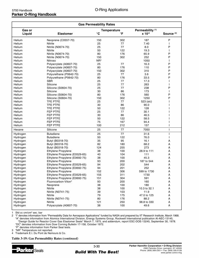
Parker O-Ring Handbook5700 Handbook O-Ring Applications
3-30
Build With The Best!SealsParker Hannifin Corporation • O-Ring Division
2360 Palumbo Drive, Lexington, KY 40509Phone: (859) 269-2351 • Fax: (859) 335-5128
www.parker.com/o-ring
1 Std cc cm/cm2 sec. bar2 “I” denotes information from “Permeability Data for Aerospace Applications” funded by NASA and prepared by IIT Research Institute, March 1968.
“A” denotes information from Atomics International Division, Energy Systems Group, Rockwell International publication AI-AEC-13145,“Design Guide for Reactor Cover Gas Elastomer Seals” March 7, 1975, and addendum, report ESC-DOE-13245, September 30, 1978.
“DC” denotes information from Dow Corning Bulletin 17-158, October 1972.“P” denotes information from Parker Seal tests.
3 “NR” Temperature not reported.4 Trademark E.I. Du Pont de Nemours & Co.
Table 3-19: Gas Permeability Rates (continued)
Gas Permeability Rates
Gas or Temperature Permeability (1)
Liquid Elastomer °C °F x 10-8 Source (2)
Helium Neoprene (C0557-70) 150 302 187 PHelium Nitrile 25 77 7.40 IHelium Nitrile (N0674-70) 25 77 8.0 PHelium Nitrile 50 122 19.3 IHelium Nitrile (N0674-70) 80 176 65.9 PHelium Nitrile (N0674-70) 150 302 252 PHelium Nitroso NR3 1050 IHelium Polyacrylate (A0607-70) 25 77 16.3 PHelium Polyacrylate (A0607-70) 80 176 110 PHelium Polyacrylate (A0607-70) 150 302 310 PHelium Polyurethane (P0642-70) 25 77 3.6 PHelium Polyurethane (P0642-70) 80 176 33.5 PHelium SBR 25 77 17.3 IHelium Silicone 25 77 263 IHelium Silicone (S0604-70) 25 77 238 PHelium Silicone 30 86 173 IHelium Silicone (S0604-70) 80 176 560 PHelium Silicone (S0604-70) 150 302 1250 PHelium TFE PTFE 25 77 523 (sic) IHelium TFE PTFE 30 86 90.0 IHelium TFE PTFE 50 122 128 IHelium FEP PTFE 25 77 30.1 IHelium FEP PTFE 30 86 46.5 IHelium FEP PTFE 50 122 58.5 IHelium FEP PTFE 75 167 94.4 IHelium FEP PTFE 100 212 157 I
Hexane Silicone 25 77 7050 I
Hydrogen Butadiene 25 77 31.6 IHydrogen Butadiene 50 122 76.0 IHydrogen Butyl (B0318-70) 35 95 16.1 AHydrogen Butyl (B0318-70) 82 180 68.2 AHydrogen Butyl (B0318-70) 124 255 273 AHydrogen Ethylene Propylene 38 100 28.9 to 111 AHydrogen Ethylene Propylene (E0529-65) 40 104 111 AHydrogen Ethylene Propylene (E0692-75) 38 100 45.3 AHydrogen Ethylene Propylene 93 200 187 to 544 AHydrogen Ethylene Propylene (E0529-65) 94 202 544 AHydrogen Ethylene Propylene (E0692-75) 94 201 252 AHydrogen Ethylene Propylene 152 306 599 to 1730 AHydrogen Ethylene Propylene (E0529-65) 155 311 1730 AHydrogen Ethylene Propylene (E0692-75) 151 304 591 AHydrogen Fluorocarbon-Viton4 93 200 160 AHydrogen Neoprene 38 100 180 AHydrogen Nitrile 38 100 10.3 to 32.1 AHydrogen Nitrile (N0741-75) 39 103 11.9 AHydrogen Nitrile 79 175 47.0 to 125 AHydrogen Nitrile (N0741-75) 80 176 88.2 AHydrogen Nitrile 121 250 98.8 to 330 AHydrogen Polyacrylate (A0607-70) 38 100 49.6 A

Parker O-Ring Handbook5700 Handbook O-Ring Applications
3-31
Build With The Best!SealsParker Hannifin Corporation • O-Ring Division
2360 Palumbo Drive, Lexington, KY 40509Phone: (859) 269-2351 • Fax: (859) 335-5128
www.parker.com/o-ring
1 Std cc cm/cm2 sec. bar2 “I” denotes information from “Permeability Data for Aerospace Applications” funded by NASA and prepared by IIT Research Institute, March 1968.
“A” denotes information from Atomics International Division, Energy Systems Group, Rockwell International publication AI-AEC-13145,“Design Guide for Reactor Cover Gas Elastomer Seals” March 7, 1975, and addendum, report ESC-DOE-13245, September 30, 1978.
“DC” denotes information from Dow Corning Bulletin 17-158, October 1972.“P” denotes information from Parker Seal tests.
3 “NR” Temperature not reported.4 Trademark E.I. Du Pont de Nemours & Co.
Table 3-19: Gas Permeability Rates (continued)
Gas Permeability Rates
Gas or Temperature Permeability (1)
Liquid Elastomer °C °F x 10-8 Source (2)
Hydrogen Polyacrylate (A0607-70) 91 195 174 AHydrogen Polyacrylate (A0607-70) 153 307 927 AHydrogen Polysulfide 25 77 1.2 IHydrogen Polyurethane (P0642-70) 39 103 19.3 AHydrogen Polyurethane (P0648-90) 39 102 4.89 AHydrogen Polyurethane (P0642-70) 66 151 70.4 AHydrogen Polyurethane (P0648-90) 67 152 21.3 AHydrogen Polyurethane (P0642-70) 94 202 155 AHydrogen SBR 25 77 30.1 IHydrogen SBR (G0244-70) 38 101 46.2 AHydrogen SBR (G0244-70) 84 183 245 AHydrogen SBR (G0244-70) 122 251 539 AHydrogen Silicone Room 188 to 488 IHydrogen Silicone 25 77 495 IHydrogen Silicone (S0684-70) 39 103 1010 AHydrogen Silicone 93 200 1570 to 2070 AHydrogen Silicone (S0684-70) 91 195 2070 AHydrogen Silicone 149 300 3300 to 8760 AHydrogen Silicone (S0684-70) 156 313 4300 AHydrogen FEP PTFE -74 -101 .0113 IHydrogen FEP PTFE -46 -51 .180 IHydrogen FEP PTFE -18 0 1.05 IHydrogen FEP PTFE 10 50 3.90 IHydrogen FEP PTFE 25 77 9.89 IHydrogen FEP PTFE 38 100 10.1 IHydrogen FEP PTFE 50 122 24.7 IHydrogen FEP PTFE 66 151 22.5 IHydrogen FEP PTFE 75 167 49.5 IHydrogen FEP PTFE 100 212 89.9 IHydrogen TFE PTFE 25 77 17.8 IHydrogen TFE PTFE 30 86 42.0 IHydrogen TFE PTFE 50 122 63.8 I
Hydrogen Sulfide Silicone 25 77 4870 I
Iodine Silicone Room 75000 I
Krypton Butyl (B0318-70) 35 95 1.39 AKrypton Butyl (B0318-70) 82 180 10.3 AKrypton Butyl (B0318-70) 124 255 54.7 AKrypton Ethylene Propylene (E0529-65) 40 104 38.6 AKrypton Ethylene Propylene (E0692-75) 38 101 16.6 AKrypton Ethylene Propylene (E0529-65) 94 202 184 AKrypton Ethylene Propylene (E0692-75) 94 201 91.2 AKrypton Ethylene Propylene (E0529-65) 155 311 324 AKrypton Ethylene Propylene (E0692-75) 151 304 289 AKrypton Fluorocarbon-Viton4 93 200 25 AKrypton Natural 35 95 47.8 IKrypton Neoprene 38 100 32 AKrypton Nitrile 38 100 .935 to 4.40 AKrypton Nitrile (N0741-75) 39 103 1.82 AKrypton Nitrile 79 175 10.7 to 30.1 A

Parker O-Ring Handbook5700 Handbook O-Ring Applications
3-32
Build With The Best!SealsParker Hannifin Corporation • O-Ring Division
2360 Palumbo Drive, Lexington, KY 40509Phone: (859) 269-2351 • Fax: (859) 335-5128
www.parker.com/o-ring
1 Std cc cm/cm2 sec. bar2 “I” denotes information from “Permeability Data for Aerospace Applications” funded by NASA and prepared by IIT Research Institute, March 1968.
“A” denotes information from Atomics International Division, Energy Systems Group, Rockwell International publication AI-AEC-13145,“Design Guide for Reactor Cover Gas Elastomer Seals” March 7, 1975, and addendum, report ESC-DOE-13245, September 30, 1978.
“DC” denotes information from Dow Corning Bulletin 17-158, October 1972.“P” denotes information from Parker Seal tests.
3 “NR” Temperature not reported.4 Trademark E.I. Du Pont de Nemours & Co.
Table 3-19: Gas Permeability Rates (continued)
Gas Permeability Rates
Gas or Temperature Permeability (1)
Liquid Elastomer °C °F x 10-8 Source (2)
Krypton Nitrile (N0741-75) 80 176 11.6 AKrypton Nitrile 121 250 27.8 to 86.6 AKrypton Nitrile (N0741-75) 118 245 48.9 AKrypton Polyacrylate (A0607-70) 38 100 14.8 AKrypton Polyacrylate (A0607-70) 91 195 90.4 AKrypton Polyacrylate (A0607-70) 153 307 464 AKrypton Polyurethane (P0642-70) 39 103 2.06 AKrypton Polyurethane (P0648-90) 39 102 .783 AKrypton Polyurethane (P0642-70) 66 151 6.53 AKrypton Polyurethane (P0648-90) 67 152 4.35 AKrypton Polyurethane (P0642-70) 94 202 31.9 AKrypton Polyurethane (P0648-90) 94 201 36.8 AKrypton SBR 38 100 7.35 to 30.8 AKrypton SBR (G0244-70) 38 101 7.35 AKrypton SBR 82 180 43.0 to 82.1 AKrypton SBR (G0244-70) 84 183 43.0 AKrypton SBR 121 250 144 to 276 AKrypton SBR (G0244-70) 122 251 144 AKrypton Silicone Room 735 IKrypton Silicone 38 100 521 to 708 AKrypton Silicone (S0684-70) 38 101 708 AKrypton Silicone 93 200 749 AKrypton Silicone (S0684-70) 91 195 1440 AKrypton Silicone 149 300 1030 to 3190 AKrypton Silicone (S0684-70) 156 313 2320 AKrypton PTFE 149 300 24 A
Methane Butadiene 25 77 9.77 IMethane Butyl 25 77 .56 IMethane Fluorocarbon 30 86 .12 IMethane Natural 25 77 22.7 IMethane Neoprene 25 77 2.6 IMethane Nitrile 25 77 2.4 IMethane Silicone 25 77 705 IMethane Silicone 30 86 443 IMethane FEP PTFE 25 77 .702 to .83 IMethane FEP PTFE 30 86 1.05 IMethane FEP PTFE 50 122 2.02 IMethane FEP PTFE 75 167 4.50 IMethane FEP PTFE 100 212 8.99 IMethane TFE PTFE 30 86 1.13 IMethane TFE PTFE 50 122 3.0 I
Methanol Silicone Room 10430 I
Neon Natural 35 95 8.5 INitric Oxide Silicone Room 450 I
Nitrogen Butadiene 25 77 3.0 INitrogen Butadiene 25 77 4.85 INitrogen Butadiene 50 122 14.3 INitrogen Butyl 25 77 .244 INitrogen Butyl 30 86 .234 I

Parker O-Ring Handbook5700 Handbook O-Ring Applications
3-33
Build With The Best!SealsParker Hannifin Corporation • O-Ring Division
2360 Palumbo Drive, Lexington, KY 40509Phone: (859) 269-2351 • Fax: (859) 335-5128
www.parker.com/o-ring
1 Std cc cm/cm2 sec. bar2 “I” denotes information from “Permeability Data for Aerospace Applications” funded by NASA and prepared by IIT Research Institute, March 1968.
“A” denotes information from Atomics International Division, Energy Systems Group, Rockwell International publication AI-AEC-13145,“Design Guide for Reactor Cover Gas Elastomer Seals” March 7, 1975, and addendum, report ESC-DOE-13245, September 30, 1978.
“DC” denotes information from Dow Corning Bulletin 17-158, October 1972.“P” denotes information from Parker Seal tests.
3 “NR” Temperature not reported.4 Trademark E.I. Du Pont de Nemours & Co.
Table 3-19: Gas Permeability Rates (continued)
Gas Permeability Rates
Gas or Temperature Permeability (1)
Liquid Elastomer °C °F x 10-8 Source (2)
Nitrogen Butyl 50 122 1.25 INitrogen Fluorocarbon 30 86 .233 INitrogen Fluorocarbon 50 122 .975 INitrogen Fluorosilicone Room 40 DCNitrogen Isoprene 25 77 5.3 INitrogen Isoprene 50 122 16.8 INitrogen Natural Room 4.8 DCNitrogen Natural 25 77 6.04 to 9.9 INitrogen Natural 30 86 6.06 to 7.9 INitrogen Natural 50 122 19.1 INitrogen Neoprene 25 77 .01 to 2 INitrogen Neoprene 30 86 .885 INitrogen Neoprene 54 129 4.35 INitrogen Neoprene 85 185 16.7 INitrogen Nitrile 20 68 .46 INitrogen Nitrile 25 77 .177 to 1.89 INitrogen Nitrile 30 86 .176 to .795 INitrogen Nitrile 50 122 1.07 to 6.9 INitrogen Nitrile 79 174 13.4 INitrogen Nitroso NR3 108 INitrogen SBR 25 77 4.7 INitrogen SBR 30 86 4.76 INitrogen Silicone Room 75 to 120 INitrogen Silicone Room 210 INitrogen Silicone 30 86 113 to 188 INitrogen Silicone 50 122 240 INitrogen TFE PTFE 25 77 2.4 INitrogen TFE PTFE 30 86 3.9 INitrogen TFE PTFE 50 122 7.5 INitrogen FEP PTFE 25 77 1.44 INitrogen FEP PTFE 30 86 1.9 INitrogen FEP PTFE 50 122 4.4 INitrogen FEP PTFE 75 167 9.2 INitrogen FEP PTFE 100 212 18.5 I
Nitrogen Dioxide Silicone Room 5701 I
Nitrogen Oxides TFE PTFE NR3 3475 INitrogen Oxides FEP PTFE NR3 485 I
Nitrogen Tetroxide TFE PTFE 25 77 0.050 to 1.00 INitrogen Tetroxide TFE PTFE 28 82 12.4 INitrogen Tetroxide TFE PTFE 28 82 3.9 I
Nitrous Oxide Silicone Room 3263 I
Octane Silicone 25 77 6450 I
Oxygen Butadiene 25 77 8.5 IOxygen Butadiene 25 77 14.3 IOxygen Butadiene 30 86 14.3 IOxygen Butadiene 50 122 35.5 IOxygen Butyl Room .98 to 1.05 IOxygen Butyl 25 77 .89 to 4.2 I
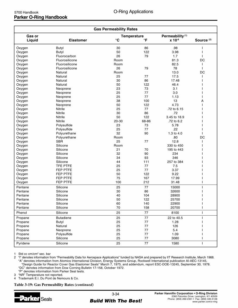
Parker O-Ring Handbook5700 Handbook O-Ring Applications
3-34
Build With The Best!SealsParker Hannifin Corporation • O-Ring Division
2360 Palumbo Drive, Lexington, KY 40509Phone: (859) 269-2351 • Fax: (859) 335-5128
www.parker.com/o-ring
1 Std cc cm/cm2 sec. bar2 “I” denotes information from “Permeability Data for Aerospace Applications” funded by NASA and prepared by IIT Research Institute, March 1968.
“A” denotes information from Atomics International Division, Energy Systems Group, Rockwell International publication AI-AEC-13145,“Design Guide for Reactor Cover Gas Elastomer Seals” March 7, 1975, and addendum, report ESC-DOE-13245, September 30, 1978.
“DC” denotes information from Dow Corning Bulletin 17-158, October 1972.“P” denotes information from Parker Seal tests.
3 “NR” Temperature not reported.4 Trademark E.I. Du Pont de Nemours & Co.
Table 3-19: Gas Permeability Rates (continued)
Gas Permeability Rates
Gas or Temperature Permeability (1)
Liquid Elastomer °C °F x 10-8 Source (2)
Oxygen Butyl 30 86 .98 IOxygen Butyl 50 122 3.98 IOxygen Fluorocarbon 26 79 1.7 IOxygen Fluorosilicone Room 81.3 DCOxygen Fluorosilicone Room 82.5 IOxygen Fluorosilicone 26 79 78 IOxygen Natural Room 13.0 DCOxygen Natural 25 77 17.5 IOxygen Natural 30 86 17.48 IOxygen Natural 50 122 46.4 IOxygen Neoprene 23 73 3.1 IOxygen Neoprene 25 77 3.0 IOxygen Neoprene 25 77 1.13 IOxygen Neoprene 38 100 13 AOxygen Neoprene 50 122 4.73 IOxygen Nitrile 25 77 .72 to 6.15 IOxygen Nitrile 30 86 .72 IOxygen Nitrile 50 122 3.45 to 18.9 IOxygen Nitrile 20-30 68-86 .72 to 6.2 IOxygen Polysulfide 23 73 5.78 IOxygen Polysulfide 25 77 .22 IOxygen Polyurethane 32 90 1.3 to 4.0 IOxygen Polyurethane Room .80 DCOxygen SBR 25 77 12.8 IOxygen Silicone Room 330 to 450 IOxygen Silicone 21 70 195 to 443 IOxygen Silicone 32 90 234 IOxygen Silicone 34 93 346 IOxygen Silicone 44 111 257 to 384 IOxygen TFE PTFE 25 77 7.5 IOxygen FEP PTFE 25 77 3.37 IOxygen FEP PTFE 50 122 9.22 IOxygen FEP PTFE 75 167 17.99 IOxygen FEP PTFE 100 212 31.48 I
Pentane Silicone 25 77 15000 IPentane Silicone 30 86 32600 IPentane Silicone 40 104 28900 IPentane Silicone 50 122 25700 IPentane Silicone 60 140 22900 IPentane Silicone 70 158 20700 I
Phenol Silicone 25 77 8100 I
Propane Butadiene 25 77 22 to 40.5 IPropane Butyl 25 77 1.28 IPropane Natural 25 77 126 IPropane Neoprene 25 77 5.4 IPropane Polysulfide 25 77 1.09 IPropane Silicone 25 77 3080 I
Pyridene Silicone 25 77 1580 I

Parker O-Ring Handbook5700 Handbook O-Ring Applications
3-35
Build With The Best!SealsParker Hannifin Corporation • O-Ring Division
2360 Palumbo Drive, Lexington, KY 40509Phone: (859) 269-2351 • Fax: (859) 335-5128
www.parker.com/o-ring
1 Std cc cm/cm2 sec. bar2 “I” denotes information from “Permeability Data for Aerospace Applications” funded by NASA and prepared by IIT Research Institute, March 1968.
“A” denotes information from Atomics International Division, Energy Systems Group, Rockwell International publication AI-AEC-13145,“Design Guide for Reactor Cover Gas Elastomer Seals” March 7, 1975, and addendum, report ESC-DOE-13245, September 30, 1978.
“DC” denotes information from Dow Corning Bulletin 17-158, October 1972.“P” denotes information from Parker Seal tests.
3 “NR” Temperature not reported.4 Trademark E.I. Du Pont de Nemours & Co.
Table 3-19: Gas Permeability Rates (continued)
Gas Permeability Rates
Gas or Temperature Permeability (1)
Liquid Elastomer °C °F x 10-8 Source (2)
Sulfur Dioxide Silicone Room 11250 I
Toluene Silicone 25 77 6850 I
Water Vapor Ethylene Propylene Room 550 to 3700 AWater Vapor Ethylene Propylene (E0692-75) Room 550 A
Xenon Butyl 25 77 .83 to 3.0 IXenon Butyl (B0318-70) 35 95 .70 AXenon Butyl (B0318-70) 82 180 6.73 AXenon Butyl (B0318-70) 124 255 38.1 AXenon Ethylene Propylene 38 100 12.2 to 44.5 AXenon Ethylene Propylene (E0529-65) 40 104 44.5 AXenon Ethylene Propylene (E0692-75) 38 100 37.8 AXenon Ethylene Propylene (E0692-75) 93 200 112 to 214 AXenon Ethylene Propylene (E0529-65) 94 202 195 AXenon Ethylene Propylene (E0692-75) 94 201 167 AXenon Ethylene Propylene 149 300 260 to 520 AXenon Ethylene Propylene (E0529-65) 155 311 520 AXenon Ethylene Propylene (E0692-75) 151 304 460 AXenon Fluorocarbon4 93 200 10 AXenon Natural 25 77 17.3 to 32.2 IXenon Natural 35 95 72.5 IXenon Neoprene 25 77 3.4 to 7.5 IXenon Neoprene 38 100 40 AXenon Nitrile 25 77 .60 to 2.85 IXenon Nitrile 38 100 .94 AXenon Nitrile (N0741-75) 38 101 3.31 AXenon Nitrile 79 175 7.83 to 36.8 AXenon Nitrile (N0741-75) 81 178 13.2 AXenon Nitrile 121 250 38.5 to 101 AXenon Polyacrylate (A0607-70) 38 100 10.9 AXenon Polyacrylate (A0607-70) 91 195 108 AXenon Polyacrylate (A0607-70) 153 307 549 AXenon Polyurethane (P0642-70) 39 103 2.57 AXenon Polyurethane (P0648-90) 39 102 1.03 AXenon Polyurethane (P0642-70) 66 151 9.58 AXenon Polyurethane (P0648-90) 67 152 6.58 AXenon Polyurethane (P0642-70) 94 202 43.0 AXenon Polyurethane (P0648-90) 94 201 24.5 AXenon SBR (G0244-70) 38 101 14.9 AXenon SBR (G0244-70) 84 183 66.2 AXenon SBR (G0244-70) 122 251 173 AXenon Silicone Room 1523 IXenon Silicone 38 100 109 to 1220 AXenon Silicone (S0684-70) 38 101 1220 AXenon Silicone 93 200 1290 to 2180 AXenon Silicone (S0684-70) 91 195 2180 AXenon Silicone (S0684-70) 148 299 700 AXenon Silicone 149 300 1110 (sic) to 2200 AXenon Silicone (S0684-70) 144 291 2200 AXenon PTFE 149 300 5.3 A

Parker O-Ring Handbook5700 Handbook Static O-Ring Sealing
4-1
Build With The Best!SealsParker Hannifin Corporation • O-Ring Division
2360 Palumbo Drive, Lexington, KY 40509Phone: (859) 269-2351 • Fax: (859) 335-5128
www.parker.com/o-ring
Section IVStatic O-Ring Sealing
4.0 Introduction ............................................................................................................................................. 4-2
4.1 Surface Finishes for Static O-Ring Seals ......................................................................................... 4-2
4.2 Static Male and Female O-Ring Design ........................................................................................... 4-2
4.3 Face Type O-Ring Seals ................................................................................................................... 4-3
4.4 Dovetail and Half-Dovetail Grooves ................................................................................................ 4-3
4.5 Boss Seals ......................................................................................................................................... 4-3
4.6 Failures and Leakage ........................................................................................................................ 4-3
4.7 O-ring Glands for Industrial Static Seals ......................................................................................... 4-4
Design Chart 4-1 .......................................................................................................................... 4-5
Design Table 4-1 .......................................................................................................................... 4-6
Face Seal Glands ............................................................................................................................. 4-14
Design Chart 4-2 ........................................................................................................................ 4-14
Dovetail Grooves ............................................................................................................................. 4-15
Design Chart 4-3 ........................................................................................................................ 4-15
Half Dovetail Grooves ..................................................................................................................... 4-16
Design Chart 4-4 ........................................................................................................................ 4-16
Tube Fitting Boss Seals — MS33649 ............................................................................................. 4-17
Design Table 4-5 ........................................................................................................................ 4-17
Tube Fitting Boss Seals — MS33656 ............................................................................................. 4-18
Design Table 4-6 ........................................................................................................................ 4-18
Design Table 4-7 ........................................................................................................................ 4-19
Vacuum Seal Glands ........................................................................................................................ 4-20
Design Chart 4-5 ........................................................................................................................ 4-20

Parker O-Ring Handbook5700 Handbook Static O-Ring Sealing
4-2
Build With The Best!SealsParker Hannifin Corporation • O-Ring Division
2360 Palumbo Drive, Lexington, KY 40509Phone: (859) 269-2351 • Fax: (859) 335-5128
www.parker.com/o-ring
4.0 Introduction
It has been said that O-rings are “the finest static seals everdeveloped.” Perhaps the prime reason for this is becausethey are almost human proof. No adjustment or humanfactor comes into play when O-rings are assembled origi-nally or used in repairs if the gland has been designed andmachined properly. O-rings do not require high boltingforces (torque) to seal perfectly. O-rings are versatile andsave space and weight. They seal over an exceptionallywide range of pressures, temperatures and tolerances. Onceseated, they continue to seal even though some feel that theytheoretically should not. In addition, they are economicaland easy to use. Therefore, we agree that the O-ring is “thefinest static seal ever developed.”
4.1 Surface Finish for Static O-Ring Seals
The design charts indicate a surface roughness value not toexceed 32 micro-inches (32 rms) on the sealing surfaces forstatic seals with a maximum of 16 rms recommended forface-type gas seals. These figures are good general guide-lines, but they do not tell the whole story.
Equally important is the method used to produce the finish.If the surface is produced by turning the part on a lathe, orby some other method that produces scratches and ridgesthat follow the direction of the groove, a very rough surfacewill still seal effectively. Some methods such as end millingor routing, however, will produce scratches that cut acrossthe O-ring. Even these may have a rather high roughnessvalue if the profile across them shows rounded “valleys”that the rubber can readily flow into. Usually, these toolmarks have sharp, deep, angular valleys that the O-ringmaterial will not penetrate or fill completely. For this typeof surface, the recommended roughness values should notbe exceeded.
4.2 Static Male and Female O-Ring Seal Design
Design Chart 4-1 and its accompanying Design Table 4-1give one set of dimensions for static O-ring seals when theconfiguration is similar to a piston or rod application withno motion involved. Aerospace Design Standard AS4716,which is shown in Design Chart 5-1 and Design Table 5-1,includes static as well as dynamic usage for the same kindof configuration.
Parker Seal Group normally recommends the 4-1 design forradial squeeze applications. The Aerospace Specificationcalls for the same squeeze on an O-ring whether it is useddynamically or statically. We feel it is preferable to applya heavier squeeze in a static application as this increasesreliability at low temperature. (The heavier squeeze shouldnot be used in a dynamic seal because it causes too muchfriction and wear.)
The Aerospace Specification design of Design Table 5-1 inmost cases requires less stretch on the inside diameter ofthe O-ring, and this would tend to reduce aging caused bystress. This can be a definite consideration in the smallersizes where the Design Table 4-1 installed stretch is wellover the recommended 5% maximum. On the other hand, inmost sizes, Design Table 4-1 dimensions allow the use ofstandard stock rod diameters and standard boring tools.This provides real savings in production, while the increasein stretch is such a small percentage over the Design Table5-1 figures that the difference in useful life would beinsignificant.
For applications requiring more than two or three percentstretch in the inside diameter of the O-rings, refer to Figure3-3 to determine the effective “W” dimension for thestretched ring. The desired percent squeeze should beapplied to this cross section diameter. In large male glandassemblies, it may be desirable to use an O-ring one sizesmaller than indicated in the design chart. The designstretch is so small in these large sizes, that the O-ring tendsto sag out of the groove before it is assembled. Using thenext smaller size simplifies assembly, but requires a re-duced gland depth to attain the proper squeeze.
The need for back-up rings should be investigated forpressures exceeding 103.5 Bar (1500 PSI) (true for all sealtypes). If there is no extrusion gap, back-up rings are notrequired. Very high pressures can be sealed without back-up rings if metal-to-metal contact (practically zero clear-ance) of the gland parts can be maintained. Instances havebeen reported of sealing pressures of 13,800 Bar (200,100PSI) with a 70 Shore A durometer O-ring without back-uprings. Vibration or pressure fluctuation sometimes willproduce “breathing” which requires back-up rings at aver-age pressures below 103.5 Bar (1500 PSI). When usingsilicone O-rings, the clearances given in the design chartsand tables should be reduced 50%.
StaticStaticStaticStaticStaticO-Ring SealingO-Ring SealingO-Ring SealingO-Ring SealingO-Ring Sealing

Parker O-Ring Handbook5700 Handbook Static O-Ring Sealing
4-3
Build With The Best!SealsParker Hannifin Corporation • O-Ring Division
2360 Palumbo Drive, Lexington, KY 40509Phone: (859) 269-2351 • Fax: (859) 335-5128
www.parker.com/o-ring
For examples of static seals, see Figure 4-1 (female gland)and Figure 4-2 (male gland).
4.3 Face Type Seals
Design Chart 4-2 explains how to design an O-ring sealwhen the groove is cut into a flat surface. Note that when thepressure is outward, the groove outside diameter (OD) isprimary, and the groove width then determines the insidediameter. Conversely, when the pressure is inward, thegroove inside diameter is primary. This design techniqueminimizes movement of the O-ring in the groove due topressure, thereby virtually eliminating wear and pumpingleakage. If this principle is used, groove diameters larger orsmaller than indicated may be used.
Two possible groove widths are shown in this chart, one forliquids, and the other for vacuum and gases. The extra widthfor liquids allows for some minimal volume swell. Insealing a liquid that is known to cause no swelling of theO-ring elastomer, the narrower groove would be suitable.
Design Chart 4-2 is preferred over Design Chart 4-1 forstatic face seals because it calls for a heavier squeeze in allbut the smallest (.070) cross-section rings, thus improvingreliability at low temperatures.
This is the same reason that the 4-1 design is preferred overthe 5-1 for static applications. In this case, however, it is thedesign rather than the fact of a static seal that permits theextra squeeze. In a male or female gland design, the amountof squeeze required by Design Chart 4-2 is quite difficult toassemble.
The 4-2 design chart is often used for vacuum seals. SeeO-Ring Applications, Section III, for assistance in findingthe best rubber material and calculating the approximateleak rate for a face type static seal used for a vacuum or agas.
Face type seals are sometimes rectangular. In designingsuch a seal to receive a standard O-ring, the inside cornerradii of the groove should be at least three times the cross-section diameter of the O-ring to avoid over-stressing thering or causing corner creases that would potentially leak.
Figure 4-1: End CapSeal
Figure 4-2: Plug Seal
Use the system pressureto close clearance gap.
Pressure
Added wall support on plug sealminimizes breathing. External threadsprevent O-ring damage during assembly.
O-ring
4.4 Dovetail and Half-Dovetail Grooves
It is sometimes necessary to mount an O-ring in a face typegroove in such a way that it cannot fall out. The dovetailgroove described in Design Charts 4-3 and 4-4 will servethis function. This groove is difficult and expensive tomachine, and the tolerances are especially critical. It shouldbe used only when it is absolutely necessary. For additionalinformation on dovetail and hald-dovetail grooves, consultthe Parker Vacuum Seal Design Guide, ORD5705.
4.5 Boss Seals
The AS568-901 through -932 O-ring sizes (Parker’s 3-series) are intended to be used for sealing straight threadtube fittings in a boss. Design Table 4-5 and Design Table4-6 show the two standard boss designs that are used for thispurpose.
Both of these bosses use the same O-ring, but Parker SealGroup recommends the Design Table 4-6 design whenthere is a choice. It is the newer design, and it has not beenfully accepted yet by industry or by the military thoughthere is a military standard for it. The 4-6 dimensionsprovide for closer tolerance control of the O-ring cavity anddistort the O-ring less when assembled. The improvedtolerance condition assures much less trouble due to leak-age resulting from insufficient squeeze or extrusion whenthe older cavity is too small. The reduced distortion gives alonger life.
4.6 Failures and Leakage
By far the most common type of failure in static O-ring sealsis extrusion. This is relatively easy to prevent if the curvesof Figure 3-2 are used when the seal assembly (groove andseal element) is designed.
“Pulsing” or “pumping” leakage occasionally occurs whensystem pressure alone causes the O-ring to rotate in thegroove and the resilience of the seal returns it to its originalposition. To avoid pumping leakage, design the gland sothat the normal position of the seal cross-section will be onthe low-pressure side of the gland or use a narrower groove.
Porous castings, eccentric grooves, out-of-tolerance parts,tool marks, and distorted or breathing glands are alsofrequent contributors to static O-ring seal malfunctioningand failure.
Cast housings, and other parts fabricated from powderedmetal are commonly vacuum impregnated with an epoxy toseal minute pores. In this impregnation process, it is stan-dard procedure to wash excess epoxy from the surface withacetone before the parts are given an oven cure. Thiswashing process may be overdone to the point where smallfissures on the surface are re-opened causing leakage underthe seal in spite of the epoxy impregnant. It is advisable,after the acetone bath, to paint the sealing surface with a

Parker O-Ring Handbook5700 Handbook Static O-Ring Sealing
4-4
Build With The Best!SealsParker Hannifin Corporation • O-Ring Division
2360 Palumbo Drive, Lexington, KY 40509Phone: (859) 269-2351 • Fax: (859) 335-5128
www.parker.com/o-ring
Design Guide 4-1: Guide for Design Table 4-1
Guide For Design Table 4-1
Select ClosestIf Desired Dimension Dimension Read Horizontally To Determine
Is Known For In Column In Column Dimension For
Bore Dia. B-1 Groove Dia. (male gland)male gland A C Plug Dia. (male gland)
G Groove width
Plug Dia. A Bore Dia. (male gland)male gland C B-1 Groove (male gland)
G Groove width
Tube OD A-1 Groove Dia. (female gland)female gland B D Throat Dia. (female gland)
G Groove width
Throat Dia. A-1 Groove Dia. (female gland)female gland D B Tube OD (female gland)
G Groove width
thin film of epoxy and wipe off the excess before ovencuring.
Leakage due to breathing, distortion, and incorrect machin-ing requires a careful analysis of the problem and a consid-eration of the possible alternatives to find the most eco-nomical solution. When one of these causes is suspected,however, the possibility of porous metal should also beconsidered.
For additional information on O-ring failures, see SectionVIII, Failure Analysis, in this handbook.
4.7 O-Ring Glands for Industrial Static Seals
On the following page, Design Chart 4-1 provides the basisfor calculating gland dimensions. For standard O-ringsizes, these dimensions have been calculated and are listedin Design Table 4-1. The procedures for the use of DesignTable 4-1 are outlined in the guide below.
After selecting gland dimensions, read horizontally todetermine proper O-ring size number. Refer to Basic O-ringElastomers and O-Ring Applications, Sections II and IIIrespectively, for help in the selection of the proper com-pound. Remember, the effective part number for an O-ringconsists of both a size number and a compound number.

Parker O-Ring Handbook5700 Handbook Static O-Ring Sealing
4-5
Build With The Best!SealsParker Hannifin Corporation • O-Ring Division
2360 Palumbo Drive, Lexington, KY 40509Phone: (859) 269-2351 • Fax: (859) 335-5128
www.parker.com/o-ring
Design Chart 4-1 — Industrial Static Seal Glands
1/2 E
Male Gland
B-1 Dia. (B-1 Min. = A Max. -2 L Max.)C Dia.A Dia.
Female Gland
1/2 E
B Dia.D Dia.
A-1 Dia.
(A-1 Max. = B Min. +2 L Max.)
Refer to Design Chart 4-1 (below) and Design Table 4-1 for dimensions
Finishes are RMS values.
(e)0° to 5°(Typ.)
63
63
R
32
G
1/2 E
F L
Gland Detail
Break CornersApprox. .005 RAD.
32
W
W
W
W
I.D.
.005Typ.
.003 Typ.
Section W-W
Pressure Pressure Pressure
G G2G1
NoParbakRing
OneParbakRing
TwoParbakRings
GlandDepth
F GrooveDepth (Ref.)
Design Chart 4-1 — For Industrial O-Ring Static Seal Glands
O-Ring W L E(a) G - Groove Width R Max.2-Size Cross-Section Gland Squeeze Diametral No Parbak One Parbak Two Parbak Groove Eccen-
AS568A- Nominal Actual Depth Actual % Clearance Ring (G) Ring (G1) Rings (G2) Radius tricity (b)
004 .070 .050 .015 22 .002 .093 .138 .205 .005through 1/16 ±.003 to to to to to to to to .002
050 .052 .023 32 .005 .098 .143 .210 .015
102 .103 .081 .017 17 .002 .140 .171 .238 .005through 3/32 ±.003 to to to to to to to to .002
178 .083 .025 24 .005 .145 .176 .243 .015
201 .139 .111 .022 16 .003 .187 .208 .275 .010through 1/8 ±.004 to to to to to to to to .003
284 .113 .032 23 .006 .192 .213 .280 .025
309 .210 .170 .032 15 .003 .281 .311 .410 .020through 3/16 ±.005 to to to to to to to to .004
395 .173 .045 21 .006 .286 .316 .415 .035
425 .275 .226 .040 15 .004 .375 .408 .538 .020through 1/4 ±.006 to to to to to to to to .005
475 .229 .055 20 .007 .380 .413 .543 .035
(a) Clearance (extrusion gap) must be held to a minimum consistent with design requirements for temperature range variation.(b) Total indicator reading between groove and adjacent bearing surface.(c) Reduce maximum diametral clearance 50% when using silicone or fluorosilicone O-rings.(d) For ease of assembly, when Parbaks are used, gland depth may be increased up to 5%.
Design Chart 4-1: For Industrial O-Ring Static Seal Glands
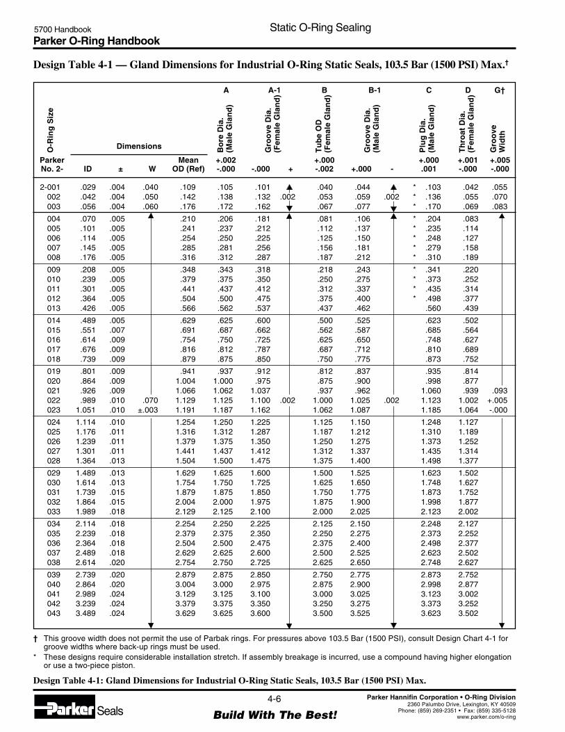
Parker O-Ring Handbook5700 Handbook Static O-Ring Sealing
4-6
Build With The Best!SealsParker Hannifin Corporation • O-Ring Division
2360 Palumbo Drive, Lexington, KY 40509Phone: (859) 269-2351 • Fax: (859) 335-5128
www.parker.com/o-ring
2-001 .029 .004 .040 .109 .105 .101 .040 .044 * .103 .042 .055002 .042 .004 .050 .142 .138 .132 .002 .053 .059 .002 * .136 .055 .070003 .056 .004 .060 .176 .172 .162 .067 .077 * .170 .069 .083
004 .070 .005 .210 .206 .181 .081 .106 * .204 .083005 .101 .005 .241 .237 .212 .112 .137 * .235 .114006 .114 .005 .254 .250 .225 .125 .150 * .248 .127007 .145 .005 .285 .281 .256 .156 .181 * .279 .158008 .176 .005 .316 .312 .287 .187 .212 * .310 .189
009 .208 .005 .348 .343 .318 .218 .243 * .341 .220010 .239 .005 .379 .375 .350 .250 .275 * .373 .252011 .301 .005 .441 .437 .412 .312 .337 * .435 .314012 .364 .005 .504 .500 .475 .375 .400 * .498 .377013 .426 .005 .566 .562 .537 .437 .462 .560 .439
014 .489 .005 .629 .625 .600 .500 .525 .623 .502015 .551 .007 .691 .687 .662 .562 .587 .685 .564016 .614 .009 .754 .750 .725 .625 .650 .748 .627017 .676 .009 .816 .812 .787 .687 .712 .810 .689018 .739 .009 .879 .875 .850 .750 .775 .873 .752
019 .801 .009 .941 .937 .912 .812 .837 .935 .814020 .864 .009 1.004 1.000 .975 .875 .900 .998 .877021 .926 .009 1.066 1.062 1.037 .937 .962 1.060 .939 .093022 .989 .010 .070 1.129 1.125 1.100 .002 1.000 1.025 .002 1.123 1.002 +.005023 1.051 .010 ±.003 1.191 1.187 1.162 1.062 1.087 1.185 1.064 -.000
024 1.114 .010 1.254 1.250 1.225 1.125 1.150 1.248 1.127025 1.176 .011 1.316 1.312 1.287 1.187 1.212 1.310 1.189026 1.239 .011 1.379 1.375 1.350 1.250 1.275 1.373 1.252027 1.301 .011 1.441 1.437 1.412 1.312 1.337 1.435 1.314028 1.364 .013 1.504 1.500 1.475 1.375 1.400 1.498 1.377
029 1.489 .013 1.629 1.625 1.600 1.500 1.525 1.623 1.502030 1.614 .013 1.754 1.750 1.725 1.625 1.650 1.748 1.627031 1.739 .015 1.879 1.875 1.850 1.750 1.775 1.873 1.752032 1.864 .015 2.004 2.000 1.975 1.875 1.900 1.998 1.877033 1.989 .018 2.129 2.125 2.100 2.000 2.025 2.123 2.002
034 2.114 .018 2.254 2.250 2.225 2.125 2.150 2.248 2.127035 2.239 .018 2.379 2.375 2.350 2.250 2.275 2.373 2.252036 2.364 .018 2.504 2.500 2.475 2.375 2.400 2.498 2.377037 2.489 .018 2.629 2.625 2.600 2.500 2.525 2.623 2.502038 2.614 .020 2.754 2.750 2.725 2.625 2.650 2.748 2.627
039 2.739 .020 2.879 2.875 2.850 2.750 2.775 2.873 2.752040 2.864 .020 3.004 3.000 2.975 2.875 2.900 2.998 2.877041 2.989 .024 3.129 3.125 3.100 3.000 3.025 3.123 3.002042 3.239 .024 3.379 3.375 3.350 3.250 3.275 3.373 3.252043 3.489 .024 3.629 3.625 3.600 3.500 3.525 3.623 3.502
† This groove width does not permit the use of Parbak rings. For pressures above 103.5 Bar (1500 PSI), consult Design Chart 4-1 forgroove widths where back-up rings must be used.
* These designs require considerable installation stretch. If assembly breakage is incurred, use a compound having higher elongationor use a two-piece piston.
Design Table 4-1: Gland Dimensions for Industrial O-Ring Static Seals, 103.5 Bar (1500 PSI) Max.
O-R
ing
Siz
e
B-1A DC
Dimensions
A-1 B G†
Bo
re D
ia.
(Mal
e G
lan
d)
Gro
ove
Dia
.(F
emal
e G
lan
d)
Gro
ove
Dia
.(M
ale
Gla
nd
)
Tu
be
OD
(Fem
ale
Gla
nd
)
Plu
g D
ia.
(Mal
e G
lan
d)
Th
roat
Dia
.(F
emal
e G
lan
d)
Gro
ove
Wid
th
IDParkerNo. 2- W±
+.002-.000
MeanOD (Ref) +-.000
+.000-.002 -+.000
+.001-.000
+.000.001
+.005-.000
Design Table 4-1 — Gland Dimensions for Industrial O-Ring Static Seals, 103.5 Bar (1500 PSI) Max.†

Parker O-Ring Handbook5700 Handbook Static O-Ring Sealing
4-7
Build With The Best!SealsParker Hannifin Corporation • O-Ring Division
2360 Palumbo Drive, Lexington, KY 40509Phone: (859) 269-2351 • Fax: (859) 335-5128
www.parker.com/o-ring
044 3.739 .027 3.879 3.875 3.850 3.750 3.775 3.873 3.752045 3.989 .027 .070 4.129 4.125 4.100 .002 4.000 4.025 .002 4.123 4.002 .093046 4.239 .030 ±.003 4.379 4.375 4.350 4.250 4.275 4.373 4.252 +.005047 4.489 .030 4.629 4.625 4.600 4.500 4.525 4.623 4.502 -.000048 4.739 .030 4.879 4.875 4.850 4.750 4.775 4.873 4.752
049 4.989 .037 5.129 5.125 5.100 5.000 5.025 5.123 5.002050 5.239 .037 5.379 5.375 5.350 5.250 5.275 5.373 5.252
102 .049 .005 .255 .247 .224 .062 .085 * .245 .064103 .081 .005 .287 .278 .256 .094 .116 * .276 .095104 .112 .005 .318 .310 .287 .125 .148 * .308 .127105 .143 .005 .349 .342 .318 .156 .180 * .340 .158106 .174 .005 .380 .374 .349 .187 .212 * .372 .189
107 .206 .005 .412 .405 .381 .219 .243 * .403 .221108 .237 .005 .443 .437 .412 .250 .275 * .435 .252109 .299 .005 .505 .500 .474 .312 .338 * .498 .314110 .362 .005 .568 .562 .537 .375 .400 * .560 .377111 .424 .005 .630 .625 .599 .437 .463 * .623 .439
112 .487 .005 .693 .687 .662 .500 .525 * .685 .502113 .549 .007 .755 .750 .724 .562 .588 * .748 .564114 .612 .009 .818 .812 .787 .625 .650 .810 .627115 .674 .009 .880 .875 .849 .687 .713 .873 .689116 .737 .009 .943 .937 .912 .750 .775 .935 .752
117 .799 .010 1.005 1.000 .974 .812 .838 .998 .814118 .862 .010 1.068 1.062 1.037 .875 .900 1.060 .877 .140119 .924 .010 .103 1.130 1.125 1.099 .002 .937 .963 .002 1.123 .939 +.005120 .987 .010 ±.003 1.193 1.187 1.162 1.000 1.025 1.185 1.002 -.000121 1.049 .010 1.255 1.250 1.224 1.062 1.088 1.248 1.064
122 1.112 .010 1.318 1.312 1.287 1.125 1.150 1.310 1.127123 1.174 .012 1.380 1.375 1.349 1.187 1.213 1.373 1.189124 1.237 .012 1.443 1.437 1.412 1.250 1.275 1.435 1.252125 1.299 .012 1.505 1.500 1.474 1.312 1.338 1.498 1.314126 1.362 .012 1.568 1.562 1.537 1.375 1.400 1.560 1.377
127 1.424 .012 1.630 1.625 1.599 1.437 1.463 1.623 1.439128 1.487 .012 1.693 1.687 1.662 1.500 1.525 1.685 1.502129 1.549 .015 1.755 1.750 1.724 1.562 1.588 1.748 1.564130 1.612 .015 1.818 1.812 1.787 1.625 1.650 1.810 1.627131 1.674 .015 1.880 1.875 1.849 1.687 1.713 1.873 1.689
132 1.737 .015 1.943 1.937 1.912 1.750 1.775 1.935 1.752133 1.799 .015 2.005 2.000 1.974 1.812 1.838 1.998 1.814134 1.862 .015 2.068 2.062 2.037 1.875 1.900 2.060 1.877135 1.925 .017 2.131 2.125 2.099 1.937 1.963 2.123 1.939136 1.987 .017 2.193 2.187 2.162 2.000 2.025 2.185 2.002
137 2.050 .017 2.256 2.250 2.224 2.062 2.088 2.248 2.064
† This groove width does not permit the use of Parbak rings. For pressures above 103.5 Bar (1500 PSI), consult Design Chart 4-1 forgroove widths where back-up rings must be used.
* These designs require considerable installation stretch. If assembly breakage is incurred, use a compound having higher elongationor use a two-piece piston.
Design Table 4-1: Gland Dimensions for Industrial O-Ring Static Seals, 103.5 Bar (1500 PSI) Max.
O-R
ing
Siz
e
B-1A DC
Dimensions
A-1 B G†
Bo
re D
ia.
(Mal
e G
lan
d)
Gro
ove
Dia
.(F
emal
e G
lan
d)
Gro
ove
Dia
.(M
ale
Gla
nd
)
Tu
be
OD
(Fem
ale
Gla
nd
)
Plu
g D
ia.
(Mal
e G
lan
d)
Th
roat
Dia
.(F
emal
e G
lan
d)
Gro
ove
Wid
th
IDParkerNo. 2- W±
+.002-.000
MeanOD (Ref) +-.000
+.000-.002 -+.000
+.001-.000
+.000.001
+.005-.000
Design Table 4-1 — Gland Dimensions for Industrial O-Ring Static Seals, 103.5 Bar (1500 PSI) Max.†(Continued)

Parker O-Ring Handbook5700 Handbook Static O-Ring Sealing
4-8
Build With The Best!SealsParker Hannifin Corporation • O-Ring Division
2360 Palumbo Drive, Lexington, KY 40509Phone: (859) 269-2351 • Fax: (859) 335-5128
www.parker.com/o-ring
138 2.112 .017 2.318 2.312 2.287 2.125 2.150 2.310 2.127139 2.175 .017 2.381 2.375 2.349 2.187 2.213 2.373 2.189140 2.237 .017 2.443 2.437 2.412 2.250 2.275 2.435 2.252141 2.300 .020 2.506 2.500 2.474 2.312 2.338 2.498 2.315142 2.362 .020 2.568 2.562 2.537 2.375 2.400 2.560 2.377
143 2.425 .020 2.631 2.625 2.599 2.437 2.463 2.623 2.439144 2.487 .020 2.693 2.687 2.662 2.500 2.525 2.685 2.502145 2.550 .020 2.756 2.750 2.724 2.562 2.588 2.748 2.564146 2.612 .020 2.818 2.812 2.787 2.625 2.650 2.810 2.627147 2.675 .022 2.881 2.875 2.849 2.687 2.713 2.873 2.689
148 2.737 .022 2.943 2.937 2.912 2.750 2.775 2.935 2.752149 2.800 .022 3.006 3.000 2.974 2.812 2.838 2.998 2.814150 2.862 .022 3.068 3.062 3.037 2.875 2.900 3.060 2.877151 2.987 .024 3.193 3.187 3.162 3.000 3.025 3.185 3.002152 3.237 .024 3.443 3.437 3.412 3.250 3.275 3.435 3.252
153 3.487 .024 3.693 3.687 3.662 3.500 3.525 3.685 3.502154 3.737 .028 .103 3.943 3.937 3.912 .002 3.750 3.775 .002 3.935 3.752 .140155 3.987 .028 ±.003 4.193 4.187 4.162 4.000 4.025 4.185 4.002 +.005156 4.237 .030 4.443 4.437 4.412 4.250 4.275 4.435 4.252 -.000157 4.487 .030 4.693 4.687 4.662 4.500 4.525 4.685 4.502
158 4.737 .030 4.943 4.937 4.912 4.750 4.775 4.935 4.752159 4.987 .035 5.193 5.187 5.162 5.000 5.025 5.185 5.002160 5.237 .035 5.443 5.437 5.412 5.250 5.275 5.435 5.252161 5.487 .035 5.693 5.687 5.662 5.500 5.525 5.685 5.502162 5.737 .035 5.943 5.937 5.912 5.750 5.775 5.935 5.752
163 5.987 .035 6.193 6.187 6.162 6.000 6.025 6.185 6.002164 6.237 .040 6.443 6.437 6.412 6.250 6.275 6.435 6.252165 6.487 .040 6.693 6.687 6.662 6.500 6.525 6.685 6.502166 6.737 .040 6.943 6.937 6.912 6.750 6.775 6.935 6.752167 6.987 .040 7.193 7.187 7.162 7.000 7.025 7.185 7.002
168 7.237 .045 7.443 7.437 7.412 7.250 7.275 7.435 7.252169 7.487 .045 7.693 7.687 7.662 7.500 7.525 7.685 7.502170 7.737 .045 7.943 7.937 7.912 7.750 7.775 7.935 7.752171 7.987 .045 8.193 8.187 8.162 8.000 8.025 8.185 8.002172 8.237 .050 8.443 8.437 8.412 8.250 8.275 8.435 8.252
173 8.487 .050 8.693 8.687 8.662 8.500 8.525 8.685 8.502174 8.737 .050 8.943 8.937 8.912 8.750 8.775 8.935 8.752175 8.987 .050 9.193 9.187 9.162 9.000 9.025 9.185 9.002176 9.237 .055 9.443 9.437 9.412 9.250 9.275 9.435 9.252177 9.487 .055 9.693 9.687 9.662 9.500 9.525 9.685 9.502
178 9.737 .055 9.943 9.937 9.912 9.750 9.775 9.935 9.752
201 .171 .005 .139 .449 .437 .409 .187 .215 * .434 .190 .187202 .234 .005 ±.004 .512 .500 .472 .002 .250 .278 .002 * .497 .253 +.005203 .296 .005 .574 .562 .534 .312 .340 * .559 .315 -.000
† This groove width does not permit the use of Parbak rings. For pressures above 103.5 Bar (1500 PSI), consult Design Chart 4-1 forgroove widths where back-up rings must be used.
* These designs require considerable installation stretch. If assembly breakage is incurred, use a compound having higher elongationor use a two-piece piston.
Design Table 4-1: Gland Dimensions for Industrial O-Ring Static Seals, 103.5 Bar (1500 PSI) Max.
O-R
ing
Siz
e
B-1A DC
Dimensions
A-1 B G†
Bo
re D
ia.
(Mal
e G
lan
d)
Gro
ove
Dia
.(F
emal
e G
lan
d)
Gro
ove
Dia
.(M
ale
Gla
nd
)
Tu
be
OD
(Fem
ale
Gla
nd
)
Plu
g D
ia.
(Mal
e G
lan
d)
Th
roat
Dia
.(F
emal
e G
lan
d)
Gro
ove
Wid
th
IDParkerNo. 2- W±
+.002-.000
MeanOD (Ref) +-.000
+.000-.002 -+.000
+.001-.000
+.000.001
+.005-.000
Design Table 4-1 — Gland Dimensions for Industrial O-Ring Static Seals, 103.5 Bar (1500 PSI) Max.†(Continued)
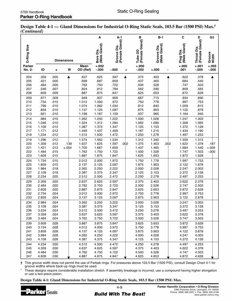
Parker O-Ring Handbook5700 Handbook Static O-Ring Sealing
4-9
Build With The Best!SealsParker Hannifin Corporation • O-Ring Division
2360 Palumbo Drive, Lexington, KY 40509Phone: (859) 269-2351 • Fax: (859) 335-5128
www.parker.com/o-ring
204 .359 .005 .637 .625 .597 .375 .403 .622 .378205 .421 .005 .699 .687 .659 .437 .465 .684 .440206 .484 .005 .762 .750 .722 .500 .528 .747 .503207 .546 .007 .824 .812 .784 .562 .590 .809 .565208 .609 .009 .887 .875 .847 .625 .653 .872 .628
209 .671 .009 .949 .937 .909 .687 .715 .934 .690210 .734 .010 1.012 1.000 .972 .750 .778 .997 .753211 .796 .010 1.074 1.062 1.034 .812 .840 1.059 .815212 .859 .010 1.137 1.125 1.097 .875 .903 1.122 .878213 .921 .010 1.199 1.187 1.159 .937 .965 1.184 .940
214 .984 .010 1.262 1.250 1.222 1.000 1.028 1.247 1.003215 1.046 .010 1.324 1.312 1.284 1.062 1.090 1.309 1.065216 1.109 .012 1.387 1.375 1.347 1.125 1.153 1.372 1.128217 1.171 .012 1.449 1.437 1.409 1.187 1.215 1.434 1.190218 1.234 .012 1.512 1.500 1.472 1.250 1.278 1.497 1.253
219 1.296 .012 1.574 1.562 1.534 1.312 1.340 1.559 1.315220 1.359 .012 .139 1.637 1.625 1.597 .002 1.375 1.403 .002 1.622 1.378 .187221 1.421 .012 ±.004 1.700 1.687 1.659 1.437 1.465 1.684 1.440 +.005222 1.484 .015 1.762 1.750 1.722 1.500 1.528 1.747 1.503 -.000223 1.609 .015 1.887 1.875 1.847 1.625 1.653 1.872 1.628
224 1.734 .015 2.012 2.000 1.972 1.750 1.778 1.997 1.753225 1.859 .015 2.137 2.125 2.097 1.875 1.903 2.122 1.878226 1.984 .018 2.262 2.250 2.222 2.000 2.028 2.247 2.003227 2.109 .018 2.387 2.375 2.347 2.125 2.153 2.372 2.128228 2.234 .020 2.512 2.500 2.472 2.250 2.278 2.497 2.253
229 2.359 .020 2.637 2.625 2.597 2.375 2.403 2.622 2.378230 2.484 .020 2.762 2.750 2.722 2.500 2.528 2.747 2.503231 2.609 .020 2.887 2.875 2.847 2.625 2.653 2.872 2.628232 2.734 .024 3.012 3.000 2.972 2.750 2.778 2.997 2.753233 2.859 .024 3.137 3.125 3.097 2.875 2.903 3.122 2.878
234 2.984 .024 3.262 3.250 3.222 3.000 3.028 3.247 3.003235 3.109 .024 3.387 3.375 3.347 3.125 3.153 3.372 3.128236 3.234 .024 3.512 3.500 3.472 3.250 3.278 3.497 3.253237 3.359 .024 3.637 3.625 3.597 3.375 3.403 3.622 3.378238 3.484 .024 3.762 3.750 3.722 3.500 3.528 3.747 3.503
239 3.609 .028 3.887 3.875 3.847 3.625 3.653 3.872 3.628240 3.734 .028 4.012 4.000 3.972 3.750 3.778 3.997 3.753241 3.859 .028 4.137 4.125 4.097 3.875 3.903 4.122 3.878242 3.984 .028 4.262 4.250 4.222 4.000 4.028 4.247 4.003243 4.109 .028 4.387 4.375 4.347 4.125 4.153 4.372 4.128
244 4.234 .030 4.512 4.500 4.472 4.250 4.278 4.497 4.253245 4.359 .030 4.637 4.625 4.597 4.375 4.403 4.622 4.378246 4.484 .030 4.762 4.750 4.722 4.500 4.528 4.747 4.503247 4.609 .030 4.887 4.875 4.847 4.625 4.653 4.872 4.628
† This groove width does not permit the use of Parbak rings. For pressures above 103.5 Bar (1500 PSI), consult Design Chart 4-1 forgroove widths where back-up rings must be used.
* These designs require considerable installation stretch. If assembly breakage is incurred, use a compound having higher elongationor use a two-piece piston.
Design Table 4-1: Gland Dimensions for Industrial O-Ring Static Seals, 103.5 Bar (1500 PSI) Max.
O-R
ing
Siz
e
B-1A DC
Dimensions
A-1 B G†
Bo
re D
ia.
(Mal
e G
lan
d)
Gro
ove
Dia
.(F
emal
e G
lan
d)
Gro
ove
Dia
.(M
ale
Gla
nd
)
Tu
be
OD
(Fem
ale
Gla
nd
)
Plu
g D
ia.
(Mal
e G
lan
d)
Th
roat
Dia
.(F
emal
e G
lan
d)
Gro
ove
Wid
th
IDParkerNo. 2- W±
+.002-.000
MeanOD (Ref) +-.000
+.000-.002 -+.000
+.001-.000
+.000.001
+.005-.000
Design Table 4-1 — Gland Dimensions for Industrial O-Ring Static Seals, 103.5 Bar (1500 PSI) Max.†(Continued)

Parker O-Ring Handbook5700 Handbook Static O-Ring Sealing
4-10
Build With The Best!SealsParker Hannifin Corporation • O-Ring Division
2360 Palumbo Drive, Lexington, KY 40509Phone: (859) 269-2351 • Fax: (859) 335-5128
www.parker.com/o-ring
248 4.734 .030 5.012 5.000 4.972 4.750 4.778 4.997 4.753249 4.859 .035 5.137 5.125 5.097 4.875 4.903 5.122 4.878250 4.984 .035 5.262 5.250 5.222 5.000 5.028 5.247 5.003251 5.109 .035 5.387 5.375 5.347 5.125 5.153 5.372 5.128252 5.234 .035 5.512 5.500 5.472 5.250 5.278 5.497 5.253
253 5.359 .035 5.637 5.625 5.597 5.375 5.403 5.622 5.378254 5.484 .035 5.762 5.750 5.722 5.500 5.528 5.747 5.503255 5.609 .035 5.887 5.875 5.847 5.625 5.653 5.872 5.628256 5.734 .035 6.012 6.000 5.972 5.750 5.778 5.997 5.753257 5.859 .035 6.137 6.125 6.097 5.875 5.903 6.122 5.878
258 5.984 .035 6.262 6.250 6.222 6.000 6.028 6.247 6.003259 6.234 .040 6.512 6.500 6.472 6.250 6.278 6.497 6.253260 6.484 .040 6.762 6.750 6.722 6.500 6.528 6.747 6.503261 6.734 .040 7.012 7.000 6.972 6.750 6.778 6.997 6.753262 6.984 .040 7.262 7.250 7.222 7.000 7.028 7.247 7.003
263 7.234 .045 7.512 7.500 7.472 7.250 7.278 7.497 7.253264 7.484 .045 7.762 7.750 7.722 7.500 7.528 7.747 7.503265 7.734 .045 .139 8.012 8.000 7.972 .002 7.750 7.778 .002 7.997 7.753 .187266 7.984 .045 ±.004 8.262 8.250 8.222 8.000 8.028 8.247 8.003 +.005267 8.234 .050 8.512 8.500 8.472 8.250 8.278 8.497 8.253 -.000
268 8.484 .050 8.762 8.750 8.722 8.500 8.528 8.747 8.503269 8.734 .050 9.012 9.000 8.972 8.750 8.778 8.997 8.753270 8.984 .050 9.262 9.250 9.222 9.000 9.028 9.247 9.003271 9.234 .055 9.512 9.500 9.472 9.250 9.278 9.497 9.253272 9.484 .055 9.762 9.750 9.722 9.500 9.528 9.747 9.503
273 9.734 .055 10.012 10.000 9.972 9.750 9.778 9.997 9.753274 9.984 .055 10.262 10.250 10.222 10.000 10.028 10.247 10.003275 10.484 .055 10.762 10.750 10.722 10.500 10.528 10.747 10.503276 10.984 .065 11.262 11.250 11.222 11.000 11.028 11.247 11.003277 11.484 .065 11.762 11.750 11.722 11.500 11.528 11.747 11.503
278 11.984 .065 12.262 12.250 12.222 12.000 12.028 12.247 12.003279 12.984 .065 13.262 13.250 13.222 13.000 13.028 13.247 13.003280 13.984 .065 14.262 14.250 14.222 14.000 14.028 14.247 14.003281 14.984 .065 15.262 15.250 15.222 15.000 15.028 15.247 15.003282 15.955 .075 16.233 16.250 16.222 16.000 16.028 16.247 16.003
283 16.955 .080 17.233 17.250 17.222 17.000 17.028 17.247 17.003284 17.955 .085 18.233 18.250 18.222 18.000 18.028 18.247 18.003
309 .412 .005 .832 .812 .777 .437 .472 * .809 .440310 .475 .005 .210 .895 .875 .840 .500 .535 * .872 .503 .281311 .537 .007 ±.005 .957 .937 .902 .004 .562 .597 .004 * .934 .565 +.005312 .600 .009 1.020 1.000 .965 .625 .660 .997 .628 -.000313 .662 .009 1.082 1.062 1.027 .687 .722 1.059 .690
314 .725 .010 1.145 1.125 1.090 .750 .785 1.122 .753
† This groove width does not permit the use of Parbak rings. For pressures above 103.5 Bar (1500 PSI), consult Design Chart 4-1 forgroove widths where back-up rings must be used.
* These designs require considerable installation stretch. If assembly breakage is incurred, use a compound having higher elongationor use a two-piece piston.
Design Table 4-1: Gland Dimensions for Industrial O-Ring Static Seals, 103.5 Bar (1500 PSI) Max.
O-R
ing
Siz
e
B-1A DC
Dimensions
A-1 B G†
Bo
re D
ia.
(Mal
e G
lan
d)
Gro
ove
Dia
.(F
emal
e G
lan
d)
Gro
ove
Dia
.(M
ale
Gla
nd
)
Tu
be
OD
(Fem
ale
Gla
nd
)
Plu
g D
ia.
(Mal
e G
lan
d)
Th
roat
Dia
.(F
emal
e G
lan
d)
Gro
ove
Wid
th
IDParkerNo. 2- W±
+.002-.000
MeanOD (Ref) +-.000
+.000-.002 -+.000
+.001-.000
+.000.001
+.005-.000
Design Table 4-1 — Gland Dimensions for Industrial O-Ring Static Seals, 103.5 Bar (1500 PSI) Max.†(Continued)

Parker O-Ring Handbook5700 Handbook Static O-Ring Sealing
4-11
Build With The Best!SealsParker Hannifin Corporation • O-Ring Division
2360 Palumbo Drive, Lexington, KY 40509Phone: (859) 269-2351 • Fax: (859) 335-5128
www.parker.com/o-ring
315 .787 .010 1.207 1.187 1.152 .812 .847 1.184 .815316 .850 .010 1.270 1.250 1.215 .875 .910 1.247 .878317 .912 .010 1.332 1.312 1.277 .937 .972 1.309 .940318 .975 .010 1.395 1.375 1.340 1.000 1.035 1.372 1.003319 1.037 .010 1.457 1.437 1.402 1.062 1.097 1.434 1.065
320 1.100 .012 1.520 1.500 1.465 1.125 1.160 1.497 1.128321 1.162 .012 1.582 1.562 1.527 1.187 1.222 1.559 1.190322 1.225 .012 1.645 1.625 1.590 1.250 1.285 1.622 1.253323 1.287 .012 1.707 1.687 1.652 1.312 1.347 1.684 1.315324 1.350 .012 1.770 1.750 1.715 1.375 1.410 1.747 1.378
325 1.475 .015 1.895 1.875 1.840 1.500 1.535 1.872 1.503326 1.600 .015 2.020 2.000 1.965 1.625 1.660 1.997 1.628327 1.725 .015 2.145 2.125 2.090 1.750 1.785 2.122 1.753328 1.850 .015 2.270 2.250 2.215 1.875 1.910 2.247 1.878329 1.975 .018 2.395 2.375 2.340 2.000 2.035 2.372 2.003
330 2.100 .018 2.520 2.500 2.465 2.125 2.160 2.497 2.128331 2.225 .018 2.645 2.625 2.590 2.250 2.285 2.622 2.253332 2.350 .018 2.770 2.750 2.715 2.375 2.410 2.747 2.378333 2.475 .020 2.895 2.875 2.840 2.500 2.535 2.872 2.503334 2.600 .020 3.020 3.000 2.965 2.625 2.660 2.997 2.628
335 2.725 .020 3.145 3.125 3.090 2.750 2.785 3.122 2.753 .281336 2.850 .020 .210 3.270 3.250 3.215 .004 2.875 2.910 .004 3.247 2.878 +.005337 2.975 .024 ±.005 3.395 3.375 3.340 3.000 3.035 3.372 3.003 -.000338 3.100 .024 3.520 3.500 3.465 3.125 3.160 3.497 3.128339 3.225 .024 3.645 3.625 3.590 3.250 3.285 3.622 3.253
340 3.350 .024 3.770 3.750 3.715 3.375 3.410 3.747 3.378341 3.475 .024 3.895 3.875 3.840 3.500 3.535 3.872 3.502342 3.600 .028 4.020 4.000 3.965 3.625 3.660 3.997 3.628343 3.725 .028 4.145 4.125 4.090 3.750 3.785 4.122 3.753344 3.850 .028 4.270 4.250 4.215 3.875 3.910 4.247 3.878
345 3.975 .028 4.395 4.375 4.340 4.000 4.035 4.372 4.003346 4.100 .028 4.520 4.500 4.465 4.125 4.160 4.497 4.128347 4.225 .030 4.645 4.625 4.590 4.250 4.285 4.622 4.253348 4.350 .030 4.770 4.750 4.717 4.375 4.410 4.747 4.378349 4.475 .030 4.895 4.875 4.840 4.500 4.535 4.872 4.503
350 4.600 .030 5.020 5.000 4.965 4.625 4.660 4.997 4.628351 4.725 .030 5.145 5.125 5.090 4.750 4.785 5.122 4.753352 4.850 .030 5.270 5.250 5.215 4.875 4.910 5.247 4.878353 4.975 .037 5.395 5.375 5.340 5.000 5.035 5.372 5.003354 5.100 .037 5.520 5.500 5.465 5.125 5.160 5.497 5.128
355 5.225 .037 5.645 5.625 5.590 5.250 5.285 5.622 5.253356 5.350 .037 5.770 5.750 5.715 5.375 5.410 5.747 5.378357 5.475 .037 5.895 5.875 5.840 5.500 5.535 5.872 5.503358 5.600 .037 6.020 6.000 5.965 5.625 5.660 5.997 5.628
† This groove width does not permit the use of Parbak rings. For pressures above 103.5 Bar (1500 PSI), consult Design Chart 4-1 forgroove widths where back-up rings must be used.
* These designs require considerable installation stretch. If assembly breakage is incurred, use a compound having higher elongationor use a two-piece piston.
Design Table 4-1: Gland Dimensions for Industrial O-Ring Static Seals, 103.5 Bar (1500 PSI) Max.
O-R
ing
Siz
e
B-1A DC
Dimensions
A-1 B G†
Bo
re D
ia.
(Mal
e G
lan
d)
Gro
ove
Dia
.(F
emal
e G
lan
d)
Gro
ove
Dia
.(M
ale
Gla
nd
)
Tu
be
OD
(Fem
ale
Gla
nd
)
Plu
g D
ia.
(Mal
e G
lan
d)
Th
roat
Dia
.(F
emal
e G
lan
d)
Gro
ove
Wid
th
IDParkerNo. 2- W±
+.002-.000
MeanOD (Ref) +-.000
+.000-.002 -+.000
+.001-.000
+.000.001
+.005-.000
Design Table 4-1 — Gland Dimensions for Industrial O-Ring Static Seals, 103.5 Bar (1500 PSI) Max.†(Continued)

Parker O-Ring Handbook5700 Handbook Static O-Ring Sealing
4-12
Build With The Best!SealsParker Hannifin Corporation • O-Ring Division
2360 Palumbo Drive, Lexington, KY 40509Phone: (859) 269-2351 • Fax: (859) 335-5128
www.parker.com/o-ring
359 5.725 .037 6.145 6.125 6.090 5.750 5.785 6.122 5.753360 5.850 .037 6.270 6.250 6.215 5.875 5.910 6.247 5.878361 5.975 .037 6.395 6.375 6.340 6.000 6.035 6.372 6.003362 6.225 .040 6.645 6.625 6.590 6.250 6.285 6.622 6.253363 6.475 .040 6.895 6.875 6.840 6.500 6.535 6.872 6.503
364 6.725 .040 7.145 7.125 7.090 6.750 6.785 7.122 6.753365 6.975 .040 7.395 7.375 7.340 7.000 7.035 7.372 7.003366 7.225 .045 7.645 7.625 7.590 7.250 7.285 7.622 7.253367 7.475 .045 7.895 7.875 7.840 7.500 7.535 7.872 7.503368 7.725 .045 8.145 8.125 8.090 7.750 7.785 8.122 7.753
369 7.975 .045 8.395 8.375 8.340 8.000 8.035 8.372 8.003370 8.225 .050 8.645 8.625 8.590 8.250 8.285 8.622 8.253371 8.475 .050 8.895 8.875 8.840 8.500 8.535 8.872 8.503372 8.725 .050 9.145 9.125 9.090 8.750 8.785 9.122 8.753373 8.975 .050 9.395 9.375 9.340 9.000 9.035 9.372 9.003
374 9.225 .055 9.645 9.625 9.590 9.250 9.285 9.622 9.253375 9.475 .055 9.895 9.875 9.840 9.500 9.535 9.872 9.503376 9.725 .055 10.145 10.125 10.090 9.750 9.785 10.122 9.753 .281377 9.975 .055 .210 10.395 10.375 10.340 .004 10.000 10.035 .004 10.372 10.003 +.005378 10.475 .060 ±.005 10.895 10.875 10.840 10.500 10.535 10.872 10.503 -.000
379 10.975 .060 11.395 11.375 11.340 11.000 11.035 11.372 11.003380 11.475 .065 11.895 11.875 11.840 11.500 11.535 11.872 11.503381 11.975 .065 12.395 12.375 12.340 12.000 12.035 12.372 12.003382 12.975 .065 13.395 13.375 13.340 13.000 13.035 13.372 13.003383 13.975 .070 14.395 14.375 14.340 14.000 14.035 14.372 14.003
384 14.975 .070 15.395 15.375 15.340 15.000 15.035 15.372 15.003385 15.955 .075 16.375 16.375 16.340 16.000 16.035 16.372 16.003386 16.955 .080 17.375 17.375 17.340 17.000 17.035 17.372 17.003387 17.955 .085 18.375 18.375 18.340 18.000 18.035 18.372 18.003388 18.955 .090 19.373 19.375 19.340 19.000 19.035 19.372 19.003
389 19.955 .095 20.373 20.375 20.340 20.000 20.035 20.372 20.003390 20.955 .095 21.373 21.375 21.340 21.000 21.035 21.372 21.003391 21.955 .100 22.373 22.375 22.340 22.000 22.035 22.372 22.003392 22.940 .105 23.360 23.375 23.340 23.000 23.035 23.372 23.003393 23.940 .110 24.360 24.375 24.340 24.000 24.035 24.372 24.003
394 24.940 .115 25.360 25.375 25.340 25.000 25.035 25.372 25.003395 25.940 .120 26.360 26.375 26.340 26.000 26.035 26.372 26.003
425 4.475 .033 5.025 5.000 4.952 4.500 4.548 4.996 4.504426 4.600 .033 5.150 5.125 5.077 4.625 4.673 5.121 4.629 .375427 4.725 .033 .275 5.275 5.250 5.202 .004 4.750 4.798 .004 5.246 4.754 +.005428 4.850 .033 ±.006 5.400 5.375 5.327 4.875 4.923 5.371 4.879 -.000429 4.975 .037 5.525 5.500 5.452 5.000 5.048 5.496 5.004
430 5.100 .037 5.650 5.625 5.577 5.125 5.173 5.621 5.129431 5.225 .037 5.775 5.750 5.702 5.250 5.298 5.746 5.254
† This groove width does not permit the use of Parbak rings. For pressures above 103.5 Bar (1500 PSI), consult Design Chart 4-1 forgroove widths where back-up rings must be used.
* These designs require considerable installation stretch. If assembly breakage is incurred, use a compound having higher elongationor use a two-piece piston.
Design Table 4-1: Gland Dimensions for Industrial O-Ring Static Seals, 103.5 Bar (1500 PSI) Max.
O-R
ing
Siz
e
B-1A DC
Dimensions
A-1 B G†
Bo
re D
ia.
(Mal
e G
lan
d)
Gro
ove
Dia
.(F
emal
e G
lan
d)
Gro
ove
Dia
.(M
ale
Gla
nd
)
Tu
be
OD
(Fem
ale
Gla
nd
)
Plu
g D
ia.
(Mal
e G
lan
d)
Th
roat
Dia
.(F
emal
e G
lan
d)
Gro
ove
Wid
th
IDParkerNo. 2- W±
+.002-.000
MeanOD (Ref) +-.000
+.000-.002 -+.000
+.001-.000
+.000.001
+.005-.000
Design Table 4-1 — Gland Dimensions for Industrial O-Ring Static Seals, 103.5 Bar (1500 PSI) Max.†(Continued)

Parker O-Ring Handbook5700 Handbook Static O-Ring Sealing
4-13
Build With The Best!SealsParker Hannifin Corporation • O-Ring Division
2360 Palumbo Drive, Lexington, KY 40509Phone: (859) 269-2351 • Fax: (859) 335-5128
www.parker.com/o-ring
432 5.350 .037 5.900 5.875 5.827 5.375 5.423 5.871 5.379433 5.475 .037 6.025 6.000 5.952 5.500 5.548 5.996 5.504434 5.600 .037 6.150 6.125 6.077 5.625 5.673 6.121 5.629435 5.725 .037 6.275 6.250 6.202 5.750 5.798 6.246 5.754436 5.850 .037 6.400 6.375 6.327 5.875 5.923 6.371 5.879
437 5.975 .037 6.525 6.500 6.452 6.000 6.048 6.496 6.004438 6.225 .040 6.775 6.750 6.702 6.250 6.298 6.746 6.254439 6.475 .040 7.025 7.000 6.952 6.500 6.548 6.996 6.504440 6.725 .040 7.275 7.250 7.202 6.750 6.798 7.246 6.754441 6.975 .040 7.525 7.500 7.452 7.000 7.048 7.496 7.004
442 7.225 .045 7.775 7.750 7.702 7.250 7.298 7.746 7.254443 7.475 .045 8.025 8.000 7.952 7.500 7.548 7.996 7.504444 7.725 .045 8.275 8.250 8.202 7.750 7.798 8.246 7.754445 7.975 .045 8.525 8.500 8.452 8.000 8.048 8.496 8.004446 8.475 .055 9.025 9.000 8.952 8.500 8.548 8.996 8.504
447 8.975 .055 9.525 9.500 9.452 9.000 9.048 9.496 9.004448 9.475 .055 10.025 10.000 9.952 9.500 9.548 9.996 9.504449 9.975 .055 10.525 10.500 10.452 10.000 10.048 10.496 10.000450 10.475 .060 11.025 11.000 10.952 10.500 10.548 10.996 10.504451 10.975 .060 11.525 11.500 11.452 11.000 11.048 11.496 11.004
452 11.475 .060 12.025 12.000 11.952 11.500 11.548 11.996 11.504453 11.975 .060 12.525 12.500 12.452 12.000 12.048 12.496 12.004 .375454 12.475 .060 .275 13.025 13.000 12.952 .004 12.500 12.548 .004 12.996 12.504 +.005455 12.975 .060 ±.006 13.525 13.500 13.452 13.000 13.048 13.496 13.004 -.000456 13.475 .070 14.025 14.000 13.952 13.500 13.548 13.996 13.504
457 13.975 .070 14.525 14.500 14.452 14.000 14.048 14.496 14.004458 14.475 .070 15.025 15.000 14.952 14.500 14.548 14.996 14.504459 14.975 .070 15.525 15.500 15.452 15.000 15.048 15.496 15.004460 15.475 .070 16.025 16.000 15.952 15.500 15.548 15.996 15.504461 15.955 .075 16.505 16.500 16.452 16.000 16.048 16.496 16.004
462 16.455 .075 17.005 17.000 16.952 16.500 16.548 16.996 16.504463 16.955 .080 17.505 17.500 17.452 17.000 17.048 17.496 17.004464 17.455 .085 18.005 18.000 17.952 17.500 17.548 17.996 17.504465 17.955 .085 18.505 18.500 18.452 18.000 18.048 18.496 18.004466 18.455 .085 19.005 19.000 18.952 18.500 18.548 18.996 18.504
467 18.955 .090 19.505 19.500 19.452 19.000 19.048 19.496 19.004468 19.455 .090 20.005 20.000 19.952 19.500 19.548 19.996 19.504469 19.955 .095 20.505 20.500 20.452 20.000 20.048 20.496 20.004470 20.955 .095 21.505 21.500 21.452 21.000 21.048 21.496 21.004471 21.955 .100 22.505 22.500 22.452 22.000 22.048 22.496 22.004
472 22.940 .105 23.490 23.500 23.452 23.000 23.048 23.496 23.004473 23.940 .110 24.490 24.500 24.452 24.000 24.048 24.496 24.004474 24.940 .115 25.490 25.500 25.452 25.000 25.048 25.496 25.004475 25.940 .120 26.490 26.500 26.452 26.000 26.048 26.496 26.004
O-R
ing
Siz
e
B-1A DC
Dimensions
A-1 B G†
Bo
re D
ia.
(Mal
e G
lan
d)
Gro
ove
Dia
.(F
emal
e G
lan
d)
Gro
ove
Dia
.(M
ale
Gla
nd
)
Tu
be
OD
(Fem
ale
Gla
nd
)
Plu
g D
ia.
(Mal
e G
lan
d)
Th
roat
Dia
.(F
emal
e G
lan
d)
Gro
ove
Wid
th
IDParkerNo. 2- W±
+.002-.000
MeanOD (Ref) +-.000
+.000-.002 -+.000
+.001-.000
+.000.001
+.005-.000
Design Table 4-1 — Gland Dimensions for Industrial O-Ring Static Seals, 103.5 Bar (1500 PSI) Max.†(Continued)
† This groove width does not permit the use of Parbak rings. For pressures above 103.5 Bar (1500 PSI), consult Design Chart 4-1 forgroove widths where back-up rings must be used.
* These designs require considerable installation stretch. If assembly breakage is incurred, use a compound having higher elongationor use a two-piece piston.
Design Table 4-1: Gland Dimensions for Industrial O-Ring Static Seals, 103.5 Bar (1500 PSI) Max.

Parker O-Ring Handbook5700 Handbook Static O-Ring Sealing
4-14
Build With The Best!SealsParker Hannifin Corporation • O-Ring Division
2360 Palumbo Drive, Lexington, KY 40509Phone: (859) 269-2351 • Fax: (859) 335-5128
www.parker.com/o-ring
Design Chart 4-2: Design Chart for O-Ring Face Seal Glands
Design Chart 4-2 — Face Seal Glands
For Internal Pressure(outward pressure direction)dimension the groove by itsoutside diameter (H ) and width:O
(H ) = Mean O.D. of O-ringO(see Table 4-1)
O.D., but not more than-.060
Tolerance = Minus 1% of Mean
For External Pressure(inward pressure direction)dimension the groove by itsinside diameter (H) and width:i
(H) = Mean I.D. of O-ringi
(see Table 4-1)
I.D., but not more than+.060
Tolerance = Plus 1% of Mean
L
0° to 5°(Typ.)
*
63
63
R
XSurface finish X:32 for liquids16 for vacuumand gases
G
LGrooveDepth(= Gland Depth)
Gland Detail
Finishes are RMS values (Refer to Design Chart A4-2 below)
Break CornersApprox. .005 RAD.
X
W
W W
I.D.
.005Max.
.003 Max.
Section W-W
W L G RO-Ring Cross Section Squeeze Groove Width
SizeParker Gland Vacuum GrooveNo. 2 Nominal Actual Depth Actual % Liquids and Gases Radius
004 .070 .050 .013 19 .101 .084 .005through 1/16 ±.003 to to to to to to
050 .054 .023 32 .107 .089 .015
102 .103 .074 .020 20 .136 .120 .005through 3/32 ±.003 to to to to to to
178 .080 .032 30 .142 .125 .015
201 .139 .101 .028 20 .177 .158 .010through 1/8 ±.004 to to to to to to
284 .107 .042 30 .187 .164 .025
309 .210 .152 .043 21 .270 .239 .020through 3/16 ±.005 to to to to to to
395 .162 .063 30 .290 .244 .035
425 .275 .201 .058 21 .342 .309 .020through 1/4 ±.006 to to to to to to
475 .211 .080 29 .362 .314 .035
.375 .276 .082 22 .475 .419 .030Special 3/8 ±.007 to to to to to to
.286 .108 28 .485 .424 .045
.500 .370 .112 22 .638 .560 .030Special 1/2 ±.008 to to to to to to
.380 .138 27 .645 .565 .045
Design Chart 4-2 — For O-Ring Face Seal GlandsThese dimensions are intended primarily for face type O-ring seals and low temperature applications.

Parker O-Ring Handbook5700 Handbook Static O-Ring Sealing
4-15
Build With The Best!SealsParker Hannifin Corporation • O-Ring Division
2360 Palumbo Drive, Lexington, KY 40509Phone: (859) 269-2351 • Fax: (859) 335-5128
www.parker.com/o-ring
Design Chart 4-3: Dovetail Grooves
66°
Mean GrooveDiameter CoincidesWith MeanO-ring Diameter. Finishes are RMS values
L
G
R
R1
Design Chart 4-3 — Dovetail Grooves
W GO-Ring Cross Section L Gland Width
Size Gland Squeeze (To sharpAS568A- Nominal Actual Depth % corner) R R1
004 .070 .050 .055through 1/16 ±.003 to 27 to .005 1/64
050 .052 .059
102 .103 .081 .083through 3/32 ±.003 to 21 to .010 1/64
178 .083 .087
201 .139 .111 .113through 1/8 ±.004 to 20 to .010 1/32
284 .113 .117
309 .210 .171 .171through 3/16 ±.005 to 18 to .015 1/32
395 .173 .175
425 .275 .231 .231through 1/4 ±.006 to 16 to .015 1/16
475 .234 .235
.375 .315 .315Special 3/8 ±.007 to 16 to .020 3/32
.319 .319
Design Chart 4-3 — For O-Ring Dovetail GroovesRadius “R” is CRITICAL. Insufficient radius will potentially cause damage to the O-ring during installation, whileexcessive radius may contribute to extrusion.
It is often necessary to provide some mechanical means forholding an O-ring in a face seal groove during assembly andmaintenance of equipment. An undercut or dovetail groove hasproven beneficial in many applications to keep the O-ring inplace. This is an expensive groove to machine, however, andthus should be used only when absolutely necessary.
It should be noted that although this method has been usedsuccessfully, it is not generally recommended. The inherentcharacteristics of the groove design limit the amount of voidarea. Normally acceptable tolerance extremes, wide servicetemperature ranges, and fluid media that cause high swell ofthe elastomer are conditions that cannot be tolerated in thistype of groove design.
NOTE: These design recommendations assume metal-to-metal contact. In special applications, for example in the semiconductorindustry, deviation from these recommendations may be necessary. When designing with ParofluorTM elastomers, one should take intoconsideration that perfluorinated elastomers may require more squeeze than an FKM material to obtain optimum sealing performance.To increase squeeze, modifications of the design recommendations shown above are necessary.

Parker O-Ring Handbook5700 Handbook Static O-Ring Sealing
4-16
Build With The Best!SealsParker Hannifin Corporation • O-Ring Division
2360 Palumbo Drive, Lexington, KY 40509Phone: (859) 269-2351 • Fax: (859) 335-5128
www.parker.com/o-ring
Design Chart 4-4 — Half Dovetail Grooves
66°
Mean GrooveDiameter CoincidesWith MeanO-ring Diameter.
L
G
R
R1
Finishes are RMS values
Design Chart 4-4: Half Dovetail Grooves
NOTE: These design recommendations assume metal-to-metal contact. In special applications, for example in the semiconductorindustry, deviation from these recommendations may be necessary. When designing with ParofluorTM elastomers, one should take intoconsideration that perfluorinated elastomers may require more squeeze than an FKM material to obtain optimum sealing performance.To increase squeeze, modifications of the design recommendations shown above are necessary.
W GO-Ring Cross Section L Gland Width
Size Gland Squeeze (To sharpAS568A- Nominal Actual Depth % corner) R R1
004 .070 .052 .064through 1/16 ±.003 to 25 to .005 1/64
050 .054 .066
102 .103 .083 .095through 3/32 ±.003 to 19 to .010 1/64
178 .085 .097
201 .139 .113 .124through 1/8 ±.004 to 18 to .010 1/32
284 .115 .128
309 .210 .173 .171through 3/16 ±.005 to 17 to .015 1/32
395 .176 .175
425 .275 .234 .255through 1/4 ±.006 to 15 to .015 1/16
475 .238 .257
.375 .319 .350Special 3/8 ±.007 to 14 to .020 3/32
.323 .358
Design Chart 4-3 — For O-Ring Dovetail GroovesRadius “R” is CRITICAL. Insufficient radius will potentially cause damage to the O-ring during installation, whileexcessive radius may contribute to extrusion.

Parker O-Ring Handbook5700 Handbook Static O-Ring Sealing
4-17
Build With The Best!SealsParker Hannifin Corporation • O-Ring Division
2360 Palumbo Drive, Lexington, KY 40509Phone: (859) 269-2351 • Fax: (859) 335-5128
www.parker.com/o-ring
*Parker dash numbers correspond with those of AS568A
Design Table 4-5: Boss Dimensions for Military Straight Thread Tube Fitting O-ring Gaskets per MS33649 (SupersedesAND10049 and AND10050)
Design Table 4-5 — Tube Fitting Boss Seals
(Note 1)GAD
120°±0° 30'
125
To G
Surf. K
Height toSuit Design
Min. ClearanceEnvelope for Fitting
BJ
.020RMax.
32C
32D Dia. to E Depth
Concentric to D Within .005 T.I.R..040.010R
E
45° ± 5°
Detail A
Thread T — PD must be square with Surf. Kwithin N T.I.R. across G Dia. Min.PD must be concentric with G Dia.within .030 T.I.R. and with D Dia.within .005 T.I.R.
Note 1:
Note 2:
Min. flat boss face. Clearance provisionsfor fitting, wrench, fitting installation andtool fillet radii must be added as required.
Tube fittings per MS33656
CMin. Dia. for unrestrictedflow of fluid may be anysize or shape providedclearance is maintained toJ depth for fitting.
Detail A
Parker Actual O-Ring Equiv. A B C D E G J NO-ring Dimensions Tube Tube Dia. Full Dia.
Size Dash OD Thread T +.015 Thd. +.005 +.015 Dia.No.* W ID No. Min. Per Mil-S-8879 -.000 Depth Dia. -.000 -.000 Min. Min.
3-902 .064 ± .003 .239 ± .005 2 .125 .3125-24UNJF-3B 0.438 0.482 0.062 0.3280.063
0.602 0.577
3-903 .064 ± .003 .301 ± .005 3 .188 .3750-24UNJF-3B 0.500 0.538 0.125 0.390 0.665 0.5830.003
3-904 .072 ± .003 .351 ± .005 4 .250 .4375-20UNJF-3B 0.5620.568
0.172 0.4540.075
0.728 0.656
3-905 .072 ± .003 .414 ± .005 5 .312 .5000-20UNJF-3B 0.625 0.234 0.517 0.790
3-906 .078 ± .003 .468 ± .005 6 .375 .5625-18UNJF-3B 0.688 0.598 0.297 0.580 0.083 0.852 0.7090.004
3-907 .082 ± .003 .530 ± .007 7 .438 .6250-18UNJF-3B 0.750 0.614 0.360 0.6430.094
0.915 0.725
3-908 .087 ± .003 .644 ± .009 8 .500 .7500-16UNJF-3B 0.875 0.714 0.391 0.769 1.040 0.834
3-909 .097 ± .003 .706 ± .009 9 .562 .8125-16UNJF-3B 0.938 0.730 0.438 0.8320.107
1.102 0.850
3-910 .097 ± .003 .755 ± .009 10 .625 .8750-14UNJF-3B 1.000 0.802 0.484 0.896 1.165 0.960
3-911 .116 ± .004 .863 ± .009 11 .688 1.0000-12UNJF-3B 1.156 0.547 1.023 1.352 0.005
3-912 .116 ± .004 .924 ± .009 12 .750 1.0625-12UNJF-3B 1.234 0.609 1.086 1.4151.064
3-914 .116 ± .004 1.047 ± .010 14 .875 1.1875-12UNJF-3B 1.362 0.734 1.211 1.540
3-916 .116 ± .004 1.171 ± .010 16 1.000 1.3125-12UNJF-3B 1.4870.877
0.844 1.336 1.665
3-918 .116 ± .004 1.355 ± .012 18 1.125 1.5000-12UNJF-3B 1.675 0.953 1.524 0.125 1.7901.116
0.008
3-920 .118 ± .004 1.475 ± .014 20 1.250 1.6250-12UNJF-3B 1.800 1.078 1.648 1.978
3-924 .118 ± .004 1.720 ± .014 24 1.500 1.8750-12UNJF-3B 2.050 1.312 1.898 2.228 1.127
3-928 .118 ± .004 2.090 ± .018 28 1.750 2.2500-12UNJF-3B 2.425 1.547 2.273 2.602 1.243 0.010
3-932 .118 ± .004 2.337 ± .018 32 2.000 2.5000-12UNJF-3B 2.675 0.907 1.781 2.524 2.852 1.368
Design Table 4-5 — Boss Dimensions for Military Straight Thread Tube Fitting O-ringGaskets per MS33649 (Supersedes AND10049 and AND10050)

Parker O-Ring Handbook5700 Handbook Static O-Ring Sealing
4-18
Build With The Best!SealsParker Hannifin Corporation • O-Ring Division
2360 Palumbo Drive, Lexington, KY 40509Phone: (859) 269-2351 • Fax: (859) 335-5128
www.parker.com/o-ring
Design Table Table 4-6: Fitting End MS33656 Used With MS16142 and MS33649 Bosses (only the dimensions that definethe O-ring cavity are shown.)
Design Table 4-6 — Tube Fitting Boss SealsUse fitting end per MS33656
*No fitting end for the 3-914 O-ring size is included in MS33656, but the dimensions shown here follow the same pattern.
F
45° ± 5°
Q
.015 RAD. for threadrunoutChamfer relief tohex flats shall bewithin the 15° ± 5°angle and K dia.limitations
.031
.016RAD K
Full threads to this pointthread T
ThreadT
Squareness betweenthread T and face ofhex shall not exceedH at measured atdiameter K
Parker E Dimension F H K QO-ring Tubing Thread Across Hex +.002 Dia. +.015
Size No. OD T Flats -.003 Max. ±.010 -.000
3-902 1/8 5/16-24 .563 .250 .549 .063
3-903 3/16 3/8-24 .625 .312 .611 .063
3-904 1/4 7/16-20 .688 +.003 .364 .674 .075
3-905 5/16 1/2-20 UNJF-3A .750 -.004 .426 .005 .736 .075
3-906 3/8 9/16-18 .813 .481 .799 .083
3-908 1/2 3/4-16 1.000 .660 .986 .094
3-910 5/8 7/8-14 1.125 .773 1.111 .107
3-912 3/7 1 1/16-12 1.375 .945 1.361
3-914* 7/8 1 3/16-12 1.500 1.070 1.475
3-916 1 1 5/16-12 UNJ-3A 1.625 ±.016 1.195 .008 1.599 .125
3-920 1 1/4 1 5/8-12 1.875 1.507 1.879
3-924 1 1/2 1 7/8-12 2.125 ±.020 1.756 2.095
3-932 2 2 1/2-12 2.750 2.381 2.718
Design Table 4-6 — Fitting End MS33656 Used with MS16142 and MS33649 Bosses(Only the dimensions that define the O-ring Cavity are shown below.)
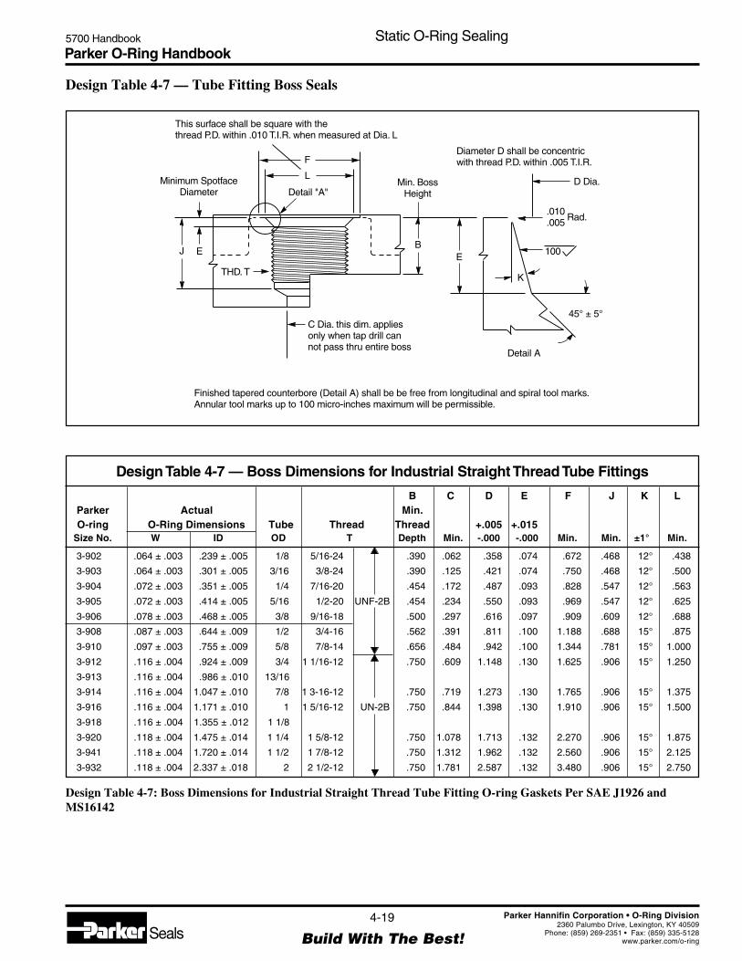
Parker O-Ring Handbook5700 Handbook Static O-Ring Sealing
4-19
Build With The Best!SealsParker Hannifin Corporation • O-Ring Division
2360 Palumbo Drive, Lexington, KY 40509Phone: (859) 269-2351 • Fax: (859) 335-5128
www.parker.com/o-ring
Design Table 4-7: Boss Dimensions for Industrial Straight Thread Tube Fitting O-ring Gaskets Per SAE J1926 andMS16142
This surface shall be square with thethread P.D. within .010 T.I.R. when measured at Dia. L
Minimum SpotfaceDiameter
F
L
Detail "A"Min. Boss
Height
Diameter D shall be concentricwith thread P.D. within .005 T.I.R.
D Dia.
.010
.005 Rad.
J E
THD. T
C Dia. this dim. appliesonly when tap drill cannot pass thru entire boss
BE
K
100
45° ± 5°
Detail A
Finished tapered counterbore (Detail A) shall be be free from longitudinal and spiral tool marks.Annular tool marks up to 100 micro-inches maximum will be permissible.
Design Table 4-7 — Tube Fitting Boss Seals
B C D E F J K LParker Actual Min.O-ring O-Ring Dimensions Tube Thread Thread +.005 +.015
Size No. W ID OD T Depth Min. -.000 -.000 Min. Min. ±1° Min.
3-902 .064 ± .003 .239 ± .005 1/8 5/16-24 .390 .062 .358 .074 .672 .468 12° .438
3-903 .064 ± .003 .301 ± .005 3/16 3/8-24 .390 .125 .421 .074 .750 .468 12° .500
3-904 .072 ± .003 .351 ± .005 1/4 7/16-20 .454 .172 .487 .093 .828 .547 12° .563
3-905 .072 ± .003 .414 ± .005 5/16 1/2-20 UNF-2B .454 .234 .550 .093 .969 .547 12° .625
3-906 .078 ± .003 .468 ± .005 3/8 9/16-18 .500 .297 .616 .097 .909 .609 12° .688
3-908 .087 ± .003 .644 ± .009 1/2 3/4-16 .562 .391 .811 .100 1.188 .688 15° .875
3-910 .097 ± .003 .755 ± .009 5/8 7/8-14 .656 .484 .942 .100 1.344 .781 15° 1.000
3-912 .116 ± .004 .924 ± .009 3/4 1 1/16-12 .750 .609 1.148 .130 1.625 .906 15° 1.250
3-913 .116 ± .004 .986 ± .010 13/16
3-914 .116 ± .004 1.047 ± .010 7/8 1 3-16-12 .750 .719 1.273 .130 1.765 .906 15° 1.375
3-916 .116 ± .004 1.171 ± .010 1 1 5/16-12 UN-2B .750 .844 1.398 .130 1.910 .906 15° 1.500
3-918 .116 ± .004 1.355 ± .012 1 1/8
3-920 .118 ± .004 1.475 ± .014 1 1/4 1 5/8-12 .750 1.078 1.713 .132 2.270 .906 15° 1.875
3-941 .118 ± .004 1.720 ± .014 1 1/2 1 7/8-12 .750 1.312 1.962 .132 2.560 .906 15° 2.125
3-932 .118 ± .004 2.337 ± .018 2 2 1/2-12 .750 1.781 2.587 .132 3.480 .906 15° 2.750
Design Table 4-7 — Boss Dimensions for Industrial Straight Thread Tube Fittings

Parker O-Ring Handbook5700 Handbook Static O-Ring Sealing
4-20
Build With The Best!SealsParker Hannifin Corporation • O-Ring Division
2360 Palumbo Drive, Lexington, KY 40509Phone: (859) 269-2351 • Fax: (859) 335-5128
www.parker.com/o-ring
Notes
Design Chart 4-5 — For Static Vacuum Seal Glands
Refer to Design Chart 4-5 (below) for dimensions.
O-Ring W L E G R Max.*Size Cross-Section Gland Squeeze Diametral Groove Groove Eccen-
AS568A- Nominal Actual Depth Actual % Clearance Width Radius tricity
004 .070 .050 .015 22 .002 .093 .005
through 1/16 ±.003 to to to to to to .002050 .052 .023 32 .005 .098 .015
102 .103 .081 .017 17 .002 .140 .005through 3/32 ±.003 to to to to to to .002
178 .083 .025 24 .005 .145 .015
201 .139 .111 .022 16 .003 .187 .010through 1/8 ±.004 to to to to to to .003
284 .113 .032 23 .006 .192 .025
309 .210 .170 .032 15 .003 .281 .020through 3/16 ±.005 to to to to to to .004
395 .173 .045 21 .006 .286 .035
425 .275 .226 .040 15 .004 .375 .020through 1/4 ±.006 to to to to to to .005
475 .229 .055 20 .007 .380 .035
Design Chart 4-5 For Static Vacuum Seal Glands
*Total indicator reading between groove and adjacent bearing surface.
Design Chart 4-5: Design Chart for Static Vacuum Seal Glands
Gland Detail
1/2E
F L
G
R
16
32
16 32
0° to 5°(Typ.)
Break CornersApprox. .005 Rad.
GlandDepth
F GrooveDepth (Ref.)
.005Typ.
W
WW
W
I.D..003 Typ.
Section W-W
Male Gland Female Gland
½ E
½ E
Finishes are RMS values

Parker O-Ring Handbook5700 Handbook Dynamic O-Ring Sealing
5-1
Build With The Best!SealsParker Hannifin Corporation • O-Ring Division
2360 Palumbo Drive, Lexington, KY 40509Phone: (859) 269-2351 • Fax: (859) 335-5128
www.parker.com/o-ring
Section VDynamic O-Ring Sealing
5.1 Introduction ............................................................................................................................................. 5-3
5.2 Hydraulic Reciprocating O-Ring Seals ................................................................................................... 5-3
5.3 Surface Finishes ...................................................................................................................................... 5-4
5.4 Temperature Effects on Dynamic Seals .................................................................................................. 5-6
5.5 Side Loads ............................................................................................................................................... 5-7
5.6 Direction of Pressure ............................................................................................................................... 5-7
5.7 Shock Loads and Pressures ..................................................................................................................... 5-7
5.8 High Frequency Motion or Vibration ...................................................................................................... 5-7
5.9 Squeeze ................................................................................................................................................... 5-7
5.10 Stretch ................................................................................................................................................... 5-8
5.11 Friction .................................................................................................................................................. 5-8
5.11.1 Break-Out Friction ...................................................................................................................... 5-8
5.11.2 Running Friction .......................................................................................................................... 5-8
5.12 Calculate Rubbing Surface ................................................................................................................... 5-9
5.13 Methods to Reduce Friction ................................................................................................................ 5-11
5.14 Friction and Wear ................................................................................................................................ 5-11
5.14.1 Friction ...................................................................................................................................... 5-11
5.14.2 Pneumatic Seals ......................................................................................................................... 5-13
5.14.3 Wear ........................................................................................................................................... 5-14
5.14.4 Interdependence of Friction Wear and an Effective Seal ........................................................... 5-14
5.15 Spiral Failure ....................................................................................................................................... 5-15
5.15.1 Speed of Stroke.......................................................................................................................... 5-16
5.15.2 Lack of Lubrication ................................................................................................................... 5-16
5.15.3 Pressure Differential and Direction ........................................................................................... 5-16
5.15.4 Squeeze ...................................................................................................................................... 5-16
5.15.5 Shape of Groove and Split Groove ............................................................................................ 5-16
5.15.6 Temperature of Operation .......................................................................................................... 5-16
5.15.7 Length of Stroke ........................................................................................................................ 5-16
5.15.8 Surface Finish ............................................................................................................................ 5-16
5.15.9 Back-Up Rings .......................................................................................................................... 5-17
5.16 Modifications for Special Applications ............................................................................................... 5-17
5.16.1 Small Amount of Leakage ......................................................................................................... 5-17
5.16.2 Early Stress-Aging .................................................................................................................... 5-17
5.16.3 Low Temperature Leakage ........................................................................................................ 5-17
5.16.4 Excessive Swell (above 20%) .................................................................................................... 5-17
5.17 Gland Dimensions for Reciprocating Hydraulic O-Ring Seals .......................................................... 5-17

Parker O-Ring Handbook5700 Handbook Dynamic O-Ring Sealing
5-2
Build With The Best!SealsParker Hannifin Corporation • O-Ring Division
2360 Palumbo Drive, Lexington, KY 40509Phone: (859) 269-2351 • Fax: (859) 335-5128
www.parker.com/o-ring
5.18 Floating Glands ................................................................................................................................... 5-17
5.19 Pneumatic Reciprocating O-Ring Seals .............................................................................................. 5-18
5.20 Temperature ........................................................................................................................................ 5-18
5.21 Silicone Compounds ........................................................................................................................... 5-18
5.22 High-Pressure ...................................................................................................................................... 5-18
5.23 Lubrication .......................................................................................................................................... 5-18
5.24 Gland Dimensions ............................................................................................................................... 5-18
5.25 Floating Seal ....................................................................................................................................... 5-19
5.26 Uni-Directional Gland ........................................................................................................................ 5-19
5.27 Rotary Seal .......................................................................................................................................... 5-19
5.28 Oscillating Seal ................................................................................................................................... 5-21
5.29 Seat Seal .............................................................................................................................................. 5-21
5.30 O-Ring Glands .................................................................................................................................... 5-23
5.30.1 O-Ring Glands for Aerospace Hydraulic Packings and Gaskets ............................................... 5-23
5.30.2 O-Ring Glands for Industrial Reciprocating Seals .................................................................... 5-33
5.30.3 O-Ring Glands for Pneumatic Floating Piston Ring Seals ........................................................ 5-38
5.30.4 O-Ring Glands for Rotary Seals ................................................................................................ 5-43
5.31 Dynamic Vacuum Sealing .................................................................................................................. 5-48

Parker O-Ring Handbook5700 Handbook Dynamic O-Ring Sealing
5-3
Build With The Best!SealsParker Hannifin Corporation • O-Ring Division
2360 Palumbo Drive, Lexington, KY 40509Phone: (859) 269-2351 • Fax: (859) 335-5128
www.parker.com/o-ring
5.1 Introduction
Dynamic O-ring sealing applications are considerably moreinvolved than static applications due to the implied motionagainst the O-ring seal interface. Resistance to fluids mustbe more carefully scrutinized than in conventional staticseal designs since a volumetric increase in the O-ring inexcess of approximately 20% may lead to friction and weardifficulties, and only a minimum of shrinkage (at most 4%),can be tolerated.
The metal or other surface over which the O-ring will movealso becomes critical. It must be hard and wear resistant. Italso must be sufficiently smooth so that it will not abradethe rubber, and yet there must be small microfine “pockets”on the moving surfaces to hold lubricant.
The greatest dynamic use of O-rings is in reciprocatinghydraulic rod and piston seals. These are discussed first, butmany of the ideas expressed are also applicable to otherdynamic applications. Considerations applying only toother types of dynamic seals are discussed in greater detaillater in the section.
5.2 Hydraulic Reciprocating O-ring Seals
O-rings are best when used on short-stroke, relativelysmall-diameter applications. Millions of O-rings however,are used very successfully in reciprocating hydraulic, pneu-matic, and other fluid systems which employ long stroke,large diameter seals. If designed properly, an O-ring sealwill give long, trouble-free service. The following discus-sion is presented so that common troubles and misuses canbe avoided.
If the engineer or designer is to become his own seal expert,he must learn the basic types and causes of seal failure. Inthis section we present a discussion of failures and causesof various seal failure modes even though it may overem-phasize the problems.
Reciprocating seals are affected by extrusion, breathing,surface finish of the metal, and hardness of the seal asdiscussed in O-Ring Applications, Section III. These fac-
tors should therefore be considered in any reciprocatinggland design. There are also additional factors discussed inthis chapter that must be considered in order to avoid futuredifficulty.
Materials for the surface(s) over which moving O-ringsslide should be chosen carefully. Those that give the maxi-mum life to moving O-ring seals are: Cast iron or steel forbores, hardened steel for rods, or hard chrome platedsurfaces.
Soft metals such as aluminum, brass, bronze, monel andsome stainless steels should be avoided in most dynamicapplications, although they may be used in low-pressurepneumatics. If the cylinder bore surface can be hardened, asby carburizing, cylinder life will be increased. Hardness ofthe piston should always be lower than the cylinder walls tominimize the possibility of damage to the cylinder boresurface.
Preferably, metallic moving surfaces sealed by an O-ringshould never touch, but if they must, then the one contain-ing the O-ring groove should be a soft bearing material. Itis impossible to run a highly polished piston rod through ahard bearing without inflicting scratches on the rod. It islikewise impossible to slide a hard piston in a highlypolished cylinder and not inflict scratches on the cylinderwall. The scratches are usually caused by small hard par-ticles that are loosened and picked up by the oil which sooneror later become jammed between the moving surfaces andscore them. Though they may be hairlines, they are longitu-dinal scratches and will therefore reduce sealing efficiencyand life of the O-ring.
The most satisfactory bearing material tried for this purposeis babbitt metal. Babbitt makes an excellent bearing and thehard particles become imbedded and captured in it withoutdamage to the hardened rod. In fact after millions of cycles,the babbitt imparts a glass-like finish to the rod. Nylon mayalso be used as a bearing material, but the bearing may needto be split in some fashion to allow for nylon’s relativelyhigh coefficient of thermal expansion.
DynamicDynamicDynamicDynamicDynamicO-Ring SealingO-Ring SealingO-Ring SealingO-Ring SealingO-Ring Sealing
Figure 5-1: O-ring Seals with Bearings
O-Ring Seals with Parbak Rings
Babbitt Bearings
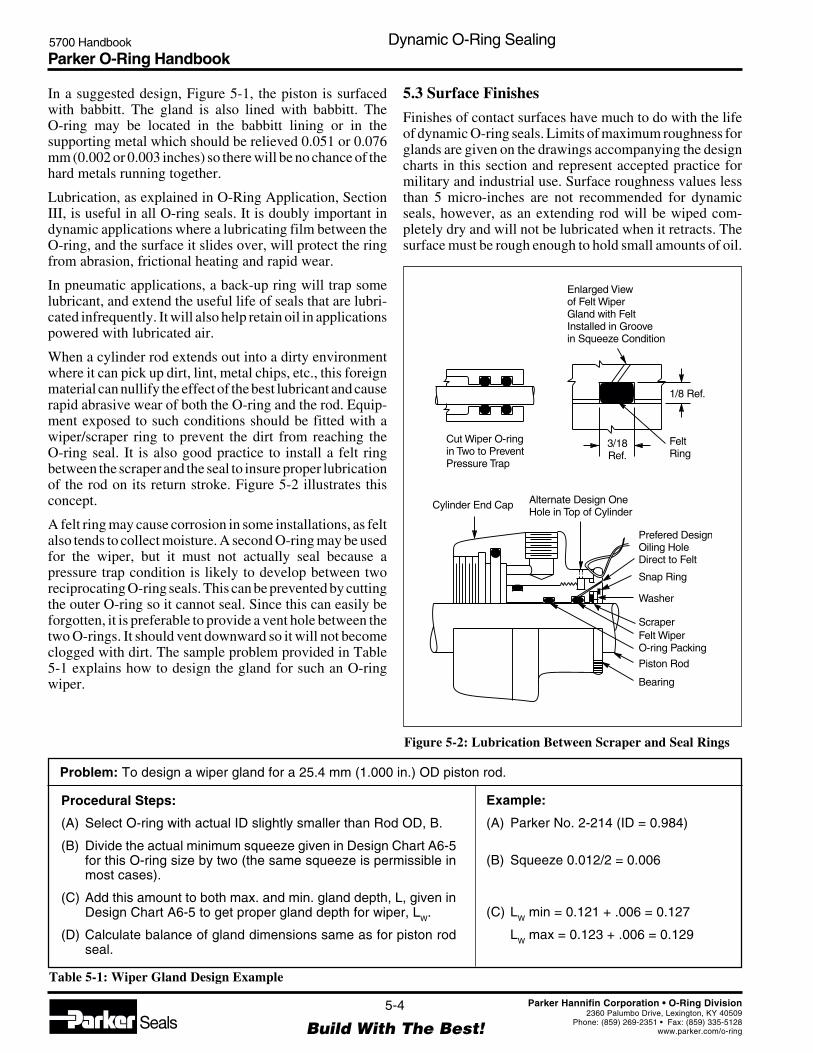
Parker O-Ring Handbook5700 Handbook Dynamic O-Ring Sealing
5-4
Build With The Best!SealsParker Hannifin Corporation • O-Ring Division
2360 Palumbo Drive, Lexington, KY 40509Phone: (859) 269-2351 • Fax: (859) 335-5128
www.parker.com/o-ring
Cut Wiper O-ringin Two to PreventPressure Trap
1/8 Ref.
FeltRing
3/18Ref.
Enlarged Viewof Felt WiperGland with FeltInstalled in Groovein Squeeze Condition
Cylinder End Cap Alternate Design OneHole in Top of Cylinder
Prefered DesignOiling HoleDirect to Felt
Snap Ring
Washer
ScraperFelt WiperO-ring Packing
Piston Rod
Bearing
In a suggested design, Figure 5-1, the piston is surfacedwith babbitt. The gland is also lined with babbitt. TheO-ring may be located in the babbitt lining or in thesupporting metal which should be relieved 0.051 or 0.076mm (0.002 or 0.003 inches) so there will be no chance of thehard metals running together.
Lubrication, as explained in O-Ring Application, SectionIII, is useful in all O-ring seals. It is doubly important indynamic applications where a lubricating film between theO-ring, and the surface it slides over, will protect the ringfrom abrasion, frictional heating and rapid wear.
In pneumatic applications, a back-up ring will trap somelubricant, and extend the useful life of seals that are lubri-cated infrequently. It will also help retain oil in applicationspowered with lubricated air.
When a cylinder rod extends out into a dirty environmentwhere it can pick up dirt, lint, metal chips, etc., this foreignmaterial can nullify the effect of the best lubricant and causerapid abrasive wear of both the O-ring and the rod. Equip-ment exposed to such conditions should be fitted with awiper/scraper ring to prevent the dirt from reaching theO-ring seal. It is also good practice to install a felt ringbetween the scraper and the seal to insure proper lubricationof the rod on its return stroke. Figure 5-2 illustrates thisconcept.
A felt ring may cause corrosion in some installations, as feltalso tends to collect moisture. A second O-ring may be usedfor the wiper, but it must not actually seal because apressure trap condition is likely to develop between tworeciprocating O-ring seals. This can be prevented by cuttingthe outer O-ring so it cannot seal. Since this can easily beforgotten, it is preferable to provide a vent hole between thetwo O-rings. It should vent downward so it will not becomeclogged with dirt. The sample problem provided in Table5-1 explains how to design the gland for such an O-ringwiper.
Problem: To design a wiper gland for a 25.4 mm (1.000 in.) OD piston rod.
Example:
(A) Parker No. 2-214 (ID = 0.984)
(B) Squeeze 0.012/2 = 0.006
(C) LW min = 0.121 + .006 = 0.127
LW max = 0.123 + .006 = 0.129
Figure 5-2: Lubrication Between Scraper and Seal Rings
5.3 Surface Finishes
Finishes of contact surfaces have much to do with the lifeof dynamic O-ring seals. Limits of maximum roughness forglands are given on the drawings accompanying the designcharts in this section and represent accepted practice formilitary and industrial use. Surface roughness values lessthan 5 micro-inches are not recommended for dynamicseals, however, as an extending rod will be wiped com-pletely dry and will not be lubricated when it retracts. Thesurface must be rough enough to hold small amounts of oil.
Procedural Steps:
(A) Select O-ring with actual ID slightly smaller than Rod OD, B.
(B) Divide the actual minimum squeeze given in Design Chart A6-5for this O-ring size by two (the same squeeze is permissible inmost cases).
(C) Add this amount to both max. and min. gland depth, L, given inDesign Chart A6-5 to get proper gland depth for wiper, L
W.
(D) Calculate balance of gland dimensions same as for piston rodseal.
Table 5-1: Wiper Gland Design Example

Parker O-Ring Handbook5700 Handbook Dynamic O-Ring Sealing
5-5
Build With The Best!SealsParker Hannifin Corporation • O-Ring Division
2360 Palumbo Drive, Lexington, KY 40509Phone: (859) 269-2351 • Fax: (859) 335-5128
www.parker.com/o-ring
RV
alue
inm
aµ
R Value in mz µ
0.160.25
0.400.63
1.01.6
2.5 6.3 16 40 100 2504.0 10 25 63 160
0.020
0.032
R-V
alue
inin
cha
µ
1
2
4
8
16
32
63
125
250
500
1000
2000
0.050
0.080
0.125
0.200
0.315
0.500
0.800
1.250
2.000
3.150
5.000
8.000
12.500
20.000
31.500
50.000
Deviation
Upper limitfor R whentransposingfrom R to R
a
z a
Upper limitfor R whentransposingfrom R to R
z
a z
Relationship Between R and Ra z
Ra
Ra
RzRz
Ideally, a microscopic “orange peel” type of surface is best,presenting smooth rounded surfaces for the O-ring to slideon, with small crevices between to act as oil reservoirs. Thiskind of surface may be approximated by peening the rodwith metal shot or glass beads. An even better surface canbe obtained by electropolishing. The most desirable surfaceroughness value is from 10 to 20 micro-inches.
The roughness of a surface as measured comprises severalelements which can be handled separately according toDIN 4760:
Level 1 — dimensional deviations withintolerance band
Level 2 — surface undulations (waves)Levels 3 to 5 — range of roughness
All these deviations from the ideal finish are superimposedas measurements are carried out and represent the surfaceroughness (see Figure 5-3).
Surface finish is often quantified in terms of Rt and Ra(see Figure 5-4). Rt is the vertical distance betweenthe highest and the lowest peaks in a roughness pro-file over a test length l
m. Rt is increasing being re-
placed by the maximum depth of roughness, Rmax. Rmax isthe greatest single roughness found in five consecutivesingle trace lengths l
m.
This is given in Figure 5-4 by the roughest profile Z4. In this
case Z4 = Rmax does not include extreme roughness peaks as
is the case of Rt.
The medium roughness value Ra is an arithmetic mean of allcomponents of the roughness trace within the trace lengthlm. The average roughness value Rz of five consecutivetrace lengths often is preferred to Re.
If Ra is known, Rz can be taken from Figure 5-5 and viceversa. Figure 5-5 is taken from DIN 4768, part 1, attach-ment 1. Should Rz reach the upper portion of the graph canbe assumed that the specified Ra values will not be ex-ceeded.
The lower limits would be taken if a Rz value should bespecified.
Figure 5-3: Surface Finish Structure
a
b
c
d
a) Dimensional Deviationsb) Surface Undulations (Waves)
c) Roughnessd) Superimposition (with a or b)
Figure 5-4: Roughness Terminology
Figure 5-5: Relationship Between Ra and R
z
R = Vertical Distance Between
Highest and Lowest Pointt
R = Depth of Roughness
R = Middle Roughness Valuep
a
Rt
Rp
Ra
Z1
l = 5 x lm e
e
Z2 Z = R4 max
R =1
5(Z + Z + Z + Z + Z )z 1 2 3 4 5
Z5Z3
R and Rmax z
lm
lm

Parker O-Ring Handbook5700 Handbook Dynamic O-Ring Sealing
5-6
Build With The Best!SealsParker Hannifin Corporation • O-Ring Division
2360 Palumbo Drive, Lexington, KY 40509Phone: (859) 269-2351 • Fax: (859) 335-5128
www.parker.com/o-ring
Table 5-2: Diagramatic Representation of Surface Profiles
Rt Rp Ra tP (%)
µm µm µm 0.25 0.50 0.75 Rt
1 0.5 0.5 50 50 50
1 0.5 0.5 50 50 75
1 0.5 0.5 50 50 75
1 0.75 0.28 12.5 25 37.5
1 0.25 0.28 62.5 75 87.5
1 0.785 0.188 3.5 14 35
1 0.215 0.188 65 86 96.5
1 0.5 0.39 43 50 57
Rp
1. Rt
Rp
2. Rt
Rp
3. Rt
Rp
4. Rt
Rp
5. Rt
Rp
6. Rt
Rp
7. Rt
Rp
8. Rt
Finally, the depth of roughness Rp also is of interest and isthe vertical distance between the highest point on theroughness trace and the center line of that trace.
Values for Rt are of very little assistance in reaching aconclusion regarding the suitability of a surface roughnessfrom the sealing point of view. Table 5-1 shows that for asimilar Rt all levels of roughness can be produced. Ra valuesare unsuitable for comparison because profiles 6 and 7 havethe same Ra value. Rp values without reference to the loadarea t
p also gives a false impression of roughness.
A static sealing surface Rt ≤ 6.3 µm (VVV roughness DIN3141) is rougher than the dynamic surface requirements.Seal manufacturers recommend a roughness Rt ≤ 2.5 µm fora dynamic sealing surface (Ra = 0.25 to 0.5 mm) (VVVroughness DIN 3141) when the load area is over 50%, orwhen the surface finish roughness Rp is under 50%. Theselimitations often are overlooked, nevertheless the connec-tion between surface finish and load area is very importantbecause an “open” profile can have sharp edges (e.g.,profiles 2 through 6 in Table 5-2). These open profiles area product of cutting processes such as turning or grinding.A much larger load area is produced by cold formingprocesses such as rolling, drawing or sinking.
It can be clearly seen from Figure 5-6 that surfaces pro-duced by roller burnishing have no sharp peaks which cancause damage to a seal. Further, the valleys form potentiallubrication reservoirs which improve the dynamic behaviorof a seal.
Figure 5-6: Surfaces Produced by Roller Burnishing (a)and by Normal Machining (b)
Rp1
Rt1
a) Cold Formed Surface
Rp2
Rt2
b) Machined Surface
Surface finish values obtained in a single test are possiblynot typical. For this reason several readings should betaken. When several results are to be compared, the lengthof the test surface must be stated — for different tracelengths, results are not comparable because they result fromother profile heights.
5.4 Temperature Effects On Dynamic Seals
High Temperatures — It should be remembered that thehigher the temperature (above 38°C) (100°F) in and arounda reciprocating gland, the more critical the applicationbecomes. The higher the interface temperature, the greaterthe tendency of the lighter fractions of the oil to evaporatefrom an exposed surface. Lack of lubrication will causegreatly accelerated seal wear. If the temperature is highenough, the tacky residue (resins) which remains after oilevaporation will char and create a hard, abrasive surfacewhich, if not removed, will quickly abrade away the sealuntil leakage or complete seal failure occurs.
Low temperatures — Low temperature environments aremost troublesome, especially if the seal has been operatingat a high temperature for some time. This is because theelastomer in the seal will take a compression set at high-temperature. When the seal is then subjected to low- tem-perature, there may be insufficient elastic memory to over-come the relatively high coefficient of shrinkage (10 timesthat of steel) at low temperatures.
Once unseated from a spot on a given metal surface, the sealmust be reseated by internal seal resilience or systempressure. Therefore, it is much easier to seal a hydraulicsystem that goes from zero-pressure to high-pressure al-most instantaneously. Low-pressure fuel, pneumatic, oil,and similar fluid systems are prone to leak if an O-ring isused as a dynamic seal at -54°C (-65°F) because there isinsufficient pressure to keep the O-ring tightly seatedduring and immediately after motion of the gland. Remem-ber that the -54°C (-65°F) compound is flexible and capableof acceptable seal performance at -54°C (-65°F) but maynot be resilient below -43°C (-45°F).

Parker O-Ring Handbook5700 Handbook Dynamic O-Ring Sealing
5-7
Build With The Best!SealsParker Hannifin Corporation • O-Ring Division
2360 Palumbo Drive, Lexington, KY 40509Phone: (859) 269-2351 • Fax: (859) 335-5128
www.parker.com/o-ring
5.5 Side Loads
Side loads on a piston or rod can cause the clearance in thegland to be on one side only. If excess clearance is createdby side-loading, extrusion will result. If adequate squeezehas not been applied, leakage will result. The higher unitload on the opposite side causes uneven friction on the seal,and if high enough, the rod or barrel will be galled or scored.
5.6 Direction of Pressure
The placement of a groove can be determined from thedirection of the system pressure in relation to the directionof the moving friction force. If the friction of the movingmetal surface across the O-ring is in the same direction asthe direction of pressure, the O-ring will tend to be draggedinto the gap more readily and thus extrude at only 30 to 40%of the pressure normally necessary to cause extrusion. Byplacing the groove in the opposite metal part, any frictionwill work against pressure. Snubbing cylinders, in whichthe motion and force create the pressure, are the usualculprits.
5.7 Shock Loads and Pressures
Shock pressures, such as those created by the suddenstopping of a rapidly descending hydraulic hoist cylinderon which there is a heavy load, are often far in excess of thepressure for which the seal and the system were designed.The same could be said about the whip of a gun barrel, ofa tank on rough roads, or a truck tailgate and others if theyare designed to ride on the hydraulic system during transit.Transient pressures of 690 Bar (10,000 PSI) are not uncom-mon in these cases. A mechanical lock or brake should beprovided to hold a position once it is attained. The hydrauliccylinder should be used only to raise and lower the load ifit does not have a relief valve within it to prevent excessivepressure build-up by shock loads.
5.8 High Frequency Motion or Vibration
O-rings or other seals can be worn excessively by smallfrequent motions which are usually encountered whenequipment is in transit. For example: the tilt cylinder of a lifttruck, a hydraulic tailgate lift, and a road scraper blade.Normally, the hydraulic cylinder is intended as an actuatorand not as a locking device or a snubber. It will be noted thatbrick pavements and dirt roads cause the most trouble whenthis type of effect is encountered. A mechanical lock is alsorecommended as a cure in this case.
5.9 Squeeze
The best squeeze for a reciprocating O-ring seal must be acompromise of all the factors involved. The design tables inthis chapter are generally satisfactory. The greater thetemperature range to be sealed, the greater the squeeze that
is needed. The same is true if low pressure or vacuums areencountered. On the other hand, too much squeeze willcause excessive friction, wear, and occasionally spiralfailure. Some rubber compounds require more squeeze thanothers in order to seal. The nitrile (buna-N) base com-pounds are recommended whenever possible because theyare more extrusion-resistant, more wear-resistant, and re-quire less squeeze to seal, than any other oil-resistant rubberdeveloped to date.
The military services have found that more than 0.432 mm(0.017") squeeze (per side) on a 5.334 mm (0.210") crosssection makes an O-ring prone to spiral failure. Yet muchless than this amount of squeeze will allow leakage at lowtemperature.
As discussed before, the amount of squeeze is a vital factorin friction. Therefore, one should carefully consider thesqueeze applied to the O-ring in any gland design.
Squeeze is actually necessary only during periods of verylow or no pressure sealing because at high pressures theO-ring seeks the path of least resistance, the clearance gap,and tends to seal tighter and tighter as the pressure isincreased.
Enough squeeze must always be provided to offset the greatdifference in coefficient of shrinkage of the rubber and themetal, take up the tolerances of the metal and rubber parts,and compensate for the shrinkage (if any) of the rubber inthe fluid. The following example illustrates how the squeezecan vary in a typical piston installation:
Consider Parker size 2-012, and from Design Table 5-2:1.With perfect concentricity
Gland Depth, Lmax = 0.501 - 0.387 = 0.057 2
Radial clearance, max = 0.501 - 0.496 = 0.0025 2
Cross section, Wmin = .067Reduction of W, due toinstallation stretch = 0.003 (see Figure 3-3)Wmin, installed = 0.064less Lmax = 0.057 (from 1. above)squeeze, min = 0.007
2.With maximum radial displacement (piston tangentwith bore)squeeze, min = 0.007 (from 1. above)radial piston shift, max = 0.0025squeeze = 0.0045 min possible
3.With maximum eccentricity of 0.002 T.I.R. betweenpiston and groove ODsqueeze, min = 0.0045 (from 2. above)radial groove shift, max = 0.0010

Parker O-Ring Handbook5700 Handbook Dynamic O-Ring Sealing
5-8
Build With The Best!SealsParker Hannifin Corporation • O-Ring Division
2360 Palumbo Drive, Lexington, KY 40509Phone: (859) 269-2351 • Fax: (859) 335-5128
www.parker.com/o-ring
squeeze, min. = 0.0035 with adversetolerance build-up.
If the O-ring is made in a compound that will shrink in thefluid, the minimum possible squeeze under adverse condi-tions then must be at least .076 mm (.003").
5.10 Stretch
When an O-ring must be stretched more than two or threepercent as installed in a piston groove, the reduction in thesqueeze diameter that results should be allowed for indetermining the gland depth so that the desired percentsqueeze will be applied to the reduced section. The percentof stretch should therefore be checked whenever the cataloggland dimensions are not used.
Large diameter O-rings may fit the piston so loosely thatthey must be carefully stuffed into the groove as the pistonenters the cylinder to prevent damage. For these, the dangerof damage is reduced if the next smaller size O-ring is used.Since this will likely cause a stretch close to five percent, itwill usually be necessary to adjust the gland depth asmentioned above. See Figure 3-3 for the reduction insqueeze diameter with stretch.
5.11 Friction
Friction, either break-out, running, or both, can becometroublesome in some applications. At any given time, thereare anomalies and difficulties in the prediction of devel-oped friction. These are accentuated if one of the surfacesinvolved is deformable as in O-ring piston or shaft seals. Anunderstanding of the principles may prove helpful in thesolution of specific problems.
5.11.1 Break-Out Friction
In addition to the usual causes of running friction: hardnessof the rubber, type of surface, surface finish, squeeze on theO-ring, amount and type of lubrication, fluid pressure/temperature, the amount of break-out friction which a
system will generate, depends on the length of time thesurfaces of the metal and the seal element have been inphysical contact at rest. See Figures 5-7 and 5-8.
The theory has been proposed and generally accepted thatthe increase of friction on standing is caused by the rub-ber O-ring flowing into the microfine grooves or surfaceirregularities of the mating part. As a general rule for a 70durometer rubber against an 8 micro-inch surface, themaximum break-out friction that will develop in a systemis 3 times the running friction. This ratio can be reduced bythe use of a softer rubber. Table 5-3 shows some of thefactors which may be used to adjust friction.
Coefficient of friction has little bearing on lubricated rubber’sbreak-out and running friction. The other variables listedare much more important in the practical solution toproblems.
5.11.2 Running Friction
High running friction may cause difficulty by wearing softmetal parts. Metals such as copper, brass or aluminum can
Figure 5-7: Change of O-ring Friction with Time at Rest
Pou
nds
of F
rict
ion Steel
8 Micro-In. RMS
Glass
Running Friction with15 Feet per MinuteStroke Speed
2-1/2 Sec. 40 Min.Delay Between Cycles
300 Hrs.
Friction Factors (In Order of Importance)
To Increase To DecreaseFriction Factor Friction
Increase Unit Load (squeeze) Decrease
Increase RMS Surface Finish (metal) Decrease RMS
Increase Durometer Decrease
Decrease Speed of Motion Increase
Increase Cross Section of O-Ring Decrease
Increase Pressure Decrease
Omit Lubrication Lubrication Use Lubrication
Decrease Temperature Increase
Decrease Groove Width Increase
Increase Diameter of Bore or Rod Decrease
Decrease Surface Finish (O-Ring) Increase
Stretch O-ring Joule Effect* Compress O-Ring
Lower Durometer Coefficient of Friction# Increase
of O-ring Durometer
* Refer to rotary seals.# A minor factor and should be ignored in design work other than for
ultra high speeds.
Table 5-3: Friction Factors
Figure 5-8: Flow of O-Ring into Metallic Surfaces
2-1/2 Sec. 40 Min.with Lubrication
300 Hrs.
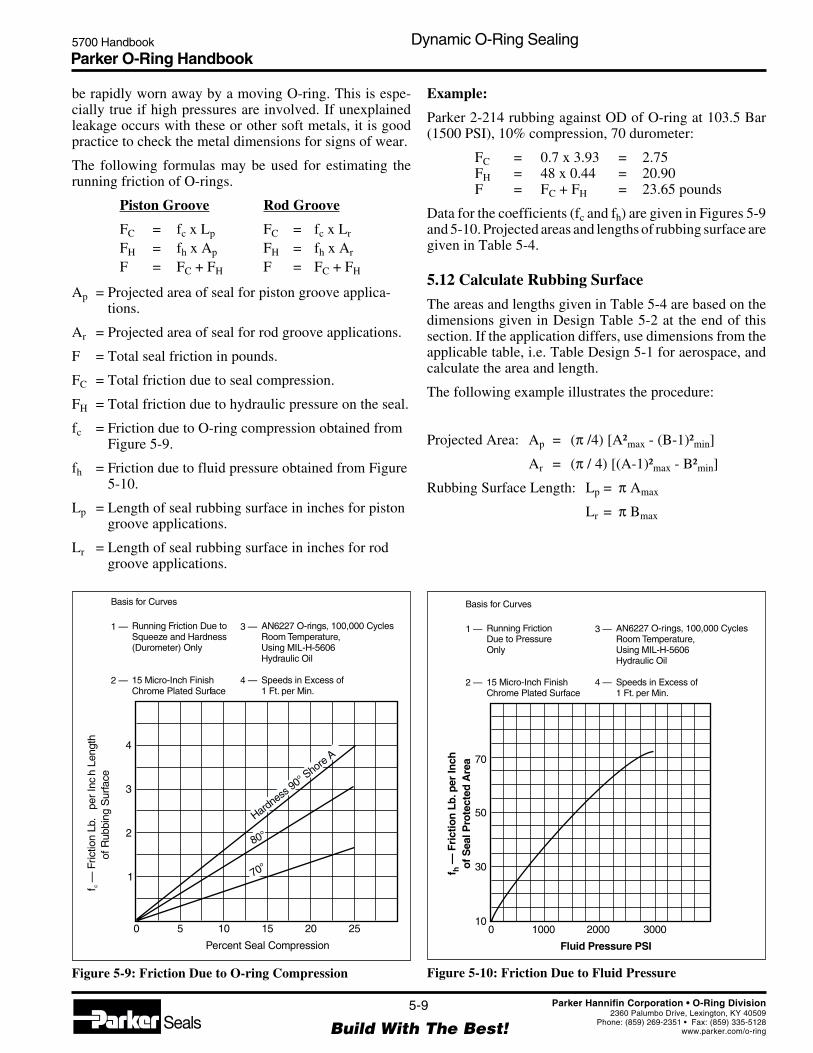
Parker O-Ring Handbook5700 Handbook Dynamic O-Ring Sealing
5-9
Build With The Best!SealsParker Hannifin Corporation • O-Ring Division
2360 Palumbo Drive, Lexington, KY 40509Phone: (859) 269-2351 • Fax: (859) 335-5128
www.parker.com/o-ring
Figure 5-9: Friction Due to O-ring Compression Figure 5-10: Friction Due to Fluid Pressure
Percent Seal Compression
Hardness90° Shore
A
70°
80°
f—
Fric
tion
Lb.
per
Inc
hLe
ngth
ofR
ubbi
ngS
urfa
cec
4
3
2
1
0 5 10 15 20 25
Basis for Curves
Running Friction Due toSqueeze and Hardness(Durometer) Only
15 Micro-Inch FinishChrome Plated Surface
1 —
2 —
AN6227 O-rings, 100,000 CyclesRoom Temperature,Using MIL-H-5606Hydraulic Oil
Speeds in Excess of1 Ft. per Min.
3 —
4 —
Fluid Pressure PSI
f—
Fri
ctio
n Lb
.per
Inch
of S
eal P
rote
cted
Are
ah
70
50
30
010
1000 2000 3000
Basis for Curves
Running FrictionDue to PressureOnly
15 Micro-Inch FinishChrome Plated Surface
1 —
2 —
AN6227 O-rings, 100,000 CyclesRoom Temperature,Using MIL-H-5606Hydraulic Oil
Speeds in Excess of1 Ft. per Min.
3 —
4 —
be rapidly worn away by a moving O-ring. This is espe-cially true if high pressures are involved. If unexplainedleakage occurs with these or other soft metals, it is goodpractice to check the metal dimensions for signs of wear.
The following formulas may be used for estimating therunning friction of O-rings.
Piston Groove Rod Groove
FC = fc x Lp FC = fc x Lr
FH = fh x Ap FH = fh x Ar
F = FC + FH F = FC + FH
Ap = Projected area of seal for piston groove applica-tions.
Ar = Projected area of seal for rod groove applications.
F = Total seal friction in pounds.
FC = Total friction due to seal compression.
FH = Total friction due to hydraulic pressure on the seal.
fc = Friction due to O-ring compression obtained fromFigure 5-9.
fh = Friction due to fluid pressure obtained from Figure5-10.
Lp = Length of seal rubbing surface in inches for pistongroove applications.
Lr = Length of seal rubbing surface in inches for rodgroove applications.
Example:
Parker 2-214 rubbing against OD of O-ring at 103.5 Bar(1500 PSI), 10% compression, 70 durometer:
FC = 0.7 x 3.93 = 2.75FH = 48 x 0.44 = 20.90F = FC + FH = 23.65 pounds
Data for the coefficients (fc and fh) are given in Figures 5-9and 5-10. Projected areas and lengths of rubbing surface aregiven in Table 5-4.
5.12 Calculate Rubbing Surface
The areas and lengths given in Table 5-4 are based on thedimensions given in Design Table 5-2 at the end of thissection. If the application differs, use dimensions from theapplicable table, i.e. Table Design 5-1 for aerospace, andcalculate the area and length.
The following example illustrates the procedure:
Projected Area: Ap = (π /4) [A²max - (B-1)²min]
Ar = (π / 4) [(A-1)²max - B²min]
Rubbing Surface Length: Lp = π Amax
Lr = π Bmax

Parker O-Ring Handbook5700 Handbook Dynamic O-Ring Sealing
5-10
Build With The Best!SealsParker Hannifin Corporation • O-Ring Division
2360 Palumbo Drive, Lexington, KY 40509Phone: (859) 269-2351 • Fax: (859) 335-5128
www.parker.com/o-ring
Projected Areas and Lengths of Rubbing Surface for O-Rings
Piston Groove Rod Groove
O-Ring Size Ap Lp Ar LrParker No. 2- Sq. In. In. Sq. In. In.
006 .03 .79 .03 .39007 .04 .89 .04 .49008 .05 .98 .04 .58009 .05 1.08 .05 .68010 .06 1.18 .05 .78
011 .07 1.38 .07 .98012 .08 1.57 .08 1.17013 .09 1.77 .09 1.37014 .10 1.97 .10 1.57015 .11 2.16 .11 1.76
016 .12 2.36 .12 1.96017 .14 2.56 .13 2.16018 .15 2.75 .14 2.35019 .16 2.95 .16 2.55020 .17 3.14 .17 2.75
021 .18 3.34 .18 2.94022 .19 3.54 .19 3.14023 .20 3.73 .20 3.33024 .21 3.93 .21 3.53025 .22 4.13 .22 3.73
026 .24 4.32 .23 3.92027 .25 4.52 .24 4.12028 .26 4.72 .26 4.32
110 .13 1.77 .13 1.17111 .15 1.97 .15 1.37112 .17 2.16 .17 1.57113 .19 2.36 .18 1.76114 .20 2.56 .20 1.96
115 .22 2.75 .22 2.16116 .24 2.95 .24 2.35117 .26 3.14 .25 2.55118 .28 3.34 .27 2.75119 .29 3.54 .29 2.94
120 .31 3.73 .31 3.14121 .33 3.93 .32 3.33122 .35 4.13 .34 3.53123 .36 4.32 .36 3.73124 .38 4.52 .38 3.92
125 .40 4.72 .40 4.12126 .42 4.91 .41 4.32127 .43 5.11 .43 4.51128 .45 5.30 .45 4.71129 .47 5.50 .47 4.90
130 .49 5.70 .48 5.10131 .50 5.89 .50 5.30132 .52 6.09 .52 5.49133 .54 6.29 .54 5.69134 .56 6.48 .55 5.89
135 .58 6.68 .57 6.08136 .59 6.88 .59 6.28137 .61 7.07 .61 6.47138 .63 7.27 .63 6.67139 .65 7.46 .64 6.87
140 .66 7.66 .66 7.07141 .68 7.86 .68 7.26142 .70 8.05 .70 7.46143 .72 8.25 .71 7.65144 .73 8.45 .73 7.85
145 .75 8.64 .75 8.05146 .77 8.84 .77 8.24147 .79 9.04 .78 8.44148 .80 9.23 .80 8.64149 .82 9.43 .82 8.83
210 .34 3.15 .34 2.35211 .36 3.34 .36 2.54212 .39 3.54 .38 2.74213 .41 3.74 .41 2.94214 .44 3.93 .43 3.14
215 .46 4.13 .46 3.33216 .48 4.33 .48 3.53217 .51 4.52 .50 3.72218 .53 4.72 .53 3.92219 .56 4.91 .55 4.12
220 .58 5.11 .58 4.31221 .61 5.31 .60 4.51222 .63 5.50 .63 4.71
325 1.00 5.90 .99 4.71326 1.07 6.29 1.07 5.10327 1.14 6.68 1.14 5.49328 1.22 7.07 1.21 5.88329 1.29 7.47 1.29 6.28
330 1.36 7.86 1.36 6.67331 1.44 8.25 1.43 7.06332 1.51 8.65 1.51 7.45333 1.58 9.04 1.58 7.85334 1.66 9.43 1.65 8.24
335 1.73 9.82 1.73 8.63336 1.81 10.22 1.80 9.03337 1.88 10.61 1.87 9.42338 1.95 11.00 1.95 9.81339 2.03 11.40 2.02 10.20
340 2.10 11.79 2.10 10.59341 2.17 12.18 2.17 10.99342 2.25 12.58 2.24 11.38343 2.32 12.97 2.31 11.77344 2.39 13.36 2.39 12.16
345 2.47 13.75 2.46 12.56346 2.54 14.15 2.54 12.95347 2.62 14.54 2.61 13.34348 2.69 14.93 2.68 13.73349 2.76 15.32 2.76 14.13
425 3.59 15.72 3.57 14.13426 3.69 16.11 3.66 14.52427 3.78 16.51 3.76 14.91428 3.87 16.90 3.85 15.31429 3.97 17.29 3.95 15.70
Piston Groove Rod Groove
O-Ring Size Ap Lp Ar LrParker No. 2- Sq. In. In. Sq. In. In.
Table 5-4: Projected Areas and Lengths of Rubbing Surface for O-rings

Parker O-Ring Handbook5700 Handbook Dynamic O-Ring Sealing
5-11
Build With The Best!SealsParker Hannifin Corporation • O-Ring Division
2360 Palumbo Drive, Lexington, KY 40509Phone: (859) 269-2351 • Fax: (859) 335-5128
www.parker.com/o-ring
Table 5-4: Projected Areas and Lengths of Rubbing Surface for O-rings, Continued
430 4.06 17.68 4.04 16.09431 4.16 18.08 4.14 16.48432 4.25 18.47 4.23 16.88433 4.35 18.86 4.32 17.27434 4.44 19.25 4.42 17.66
435 4.53 19.65 4.51 18.05436 4.63 20.04 4.61 18.45437 4.72 20.43 4.70 18.84438 4.91 21.22 4.89 19.63439 5.10 22.00 5.08 20.41
440 5.29 22.79 5.27 21.20441 5.48 23.57 5.46 21.98442 5.67 24.36 5.64 22.77443 5.85 25.15 5.83 23.55444 6.04 25.93 6.02 24.34
Projected Areas and Lengths of Rubbing Surface for O-Rings
Piston Groove Rod Groove
O-Ring Size Ap Lp Ar LrParker No. 2- Sq. In. In. Sq. In. In.
Piston Groove Rod Groove
O-Ring Size Ap Lp Ar LrParker No. 2- Sq. In. In. Sq. In. In.
445 6.23 26.72 6.21 25.12446 6.61 28.29 6.59 26.69447 6.98 29.86 6.96 28.26448 7.36 31.43 7.34 29.84449 7.74 33.00 7.72 31.41
450 8.12 34.57 8.09 32.98451 8.49 36.14 8.47 34.55452 8.87 37.71 8.85 36.12453 9.25 39.28 9.22 37.69454 9.62 40.85 9.60 39.26
455 10.00 42.42 9.98 40.83456 10.38 43.99 10.36 42.40457 10.75 45.57 10.73 43.97458 11.13 47.14 11.11 45.54459 11.51 48.71 11.49 47.11460 11.89 50.28 11.86 48.69
For Parker Size No. 2-113:
Amax = 0.751 Bmin = 0.559A-1max = 0.739 B-1min = 0.571Bmax = 0.561
Projected Area:
Ap = (π/4) [(0.751 )²- (0.571)²] = 0.187 sq. in.
Ar = (π/4) [(0.739)² - (0.559)²] = 0.184 sq. in.
Rubbing Surface Length:
Lp = 0.751π = 2.36 in.
Lr = 0.561π = 1.76 in.
5.13 Methods To Reduce Friction
The foregoing formulas for estimating O-ring friction areintended for applications in which standard O-ring com-pound types are to be used in systems lubricated withhydraulic oil. In pneumatic or other dynamic applications,Parker Seal can help reduce friction in several ways. O-Lubeand Super-O-Lube greases are available from Parker dis-tributors, and O-rings may be ordered that have receivedspecial friction reducing treatments. These include inter-nally lubricated rings and Lube Treated rings.
5.14 Friction and Wear
O-rings load a sealing surface due to their own resiliencecompounded with any system pressure. When the surface tobe sealed moves relative to the O-ring, frictional forces areset up producing two effects: one leads to wear and the otherreduces the useful load which a cylinder can transmit.
5.14.1 Friction
In dynamic applications difference must be made betweenbreak-out and running friction. Break-out friction must beovercome at the beginning of movement and also is knownas start-up friction. Once movement is established thefrictional forces drop to a lower level and gliding begins.This can be clearly seen in reciprocating cylinders.
The running friction of seals depends on countless factorsmaking a mathematical analysis practically impossible. Forthis reason it is difficult to make exact statements regardingthe level of friction which can be expected. The mostimportant factors are:
Related to the seal:• Geometrical form including production tolerances and
resulting deformation;• hardness and surface finish;• friction values for dry and lubricated compound;• swell and temperature characteristics.
Related to the hydraulic fluid:• Tendency to build up a lubricating film and its distribu-
tion;• viscosity and temperature/viscosity relationship.
Related to the working conditions:• Working pressure;• velocity of movement;• type of material and surface finish of surfaces;• working tolerances;• axial loads and wear bands on pistons.

Parker O-Ring Handbook5700 Handbook Dynamic O-Ring Sealing
5-12
Build With The Best!SealsParker Hannifin Corporation • O-Ring Division
2360 Palumbo Drive, Lexington, KY 40509Phone: (859) 269-2351 • Fax: (859) 335-5128
www.parker.com/o-ring
These factors cannot be quantified because they overlapand act cumulatively.
At the beginning of a stroke the seal goes through threefriction phases. Initially the seal is in direct contact with thesealing face with few lubricated fields, e.g., µ = 0.3. Thenfollows a wider area of mixed friction where the coefficientof friction can drop as low as 0.06 to 0.08 according to theproportion of lubrication/non-lubricated areas (Figure 5-11).Finally, pure hydrodynamic friction which does not allowdirect contact between the seal and the running surfaces israrely reached.
As complete lubrication (= flooding) occurs, loss of fluidfrom a system increases.
Friction depends on a compound's sliding properties. Hard-ness and deformation of the seal influence the seal pressure.Specific seal pressure is in general related to, but not strictlyproportional, to the system pressure.
The working pressure controls the width of clearance gapsand thereby the thickness of the lubricating film. The resultdepends on the geometry of the seal. Friction caused byO-rings increases with increasing pressure. Lip seals aremore sensitive to pressure, friction increases quicker thanwith seals without lip. This shows that the geometry of aseal directly affects the amount of friction.
Friction is proportional to the working pressure and there-fore it is necessary to keep seal friction low, especially atlow pressures.
Unfortunately, reduction of the sealing force also results inan increased tendency to leakage. This relationship can bemodified within certain limits by selection of the sealgeometry. Normally the decision must be made betweenlower friction and high leakage.
Additionally, an unstable seal geometry due to swelling inthe medium plays a role. Swelling means increase sealingforce and increased friction.
When the medium is mineral oil it would seem that suffi-cient lubrication is assured. However, the seal geometryonce again plays a role when, for example, a wiper sealscrapes a shaft dry. Leakage at a wiper seal will not occuruntil the seal wears. On the other hand lubrication can causeleakage amounting to the thick lubricating film with everystroke.
The optimum condition is a relatively thin lubricating filmwith sufficient adhesive properties.
The dynamic piston actually causes less friction with in-creasing velocity. In absolute terms there are very largediscrepancies according to the thickness of the lubricatingfilm. The reduction of friction with increasing velocitystems from the hydrodynamic properties of the lubricatingfluid. This is also true for harder compounds. At lowpressures the friction varies to the piston speed. At highpressures friction is seen to be more or less constant.
Friction is directly influenced by the seal diameter becausethe wear-area is greater. The greater the metal surfaceroughness, the more the contact surface consists of metallic“islands” and therefore again mixed friction occurs.
As in many other areas break-out friction of elastomers issignificantly higher than running friction. Apart from com-pound type and seal geometry, tendency to adhesion, defor-mation, the down-time and the surface finish play a role inincreasing break-out friction. The longer the down-time,the more lubrication is squeezed from between the seal andthe running surface resulting in a non-lubricated vacuum.In this condition the level of starting friction approachesthat for dry friction and is up to 10 times that found inrunning friction (Figures 5-12 and 5-11).
For the same conditions, friction at high temperature (= lowviscosity) is high because the lubricating film is ofteninterrupted.
Figure 5-11: Stribeck Diagram
Velocity VV min.µ
Coe
ffici
ent o
f Fric
tion
µ
Mixed friction
Break-out friction
Hydro-dynamic friction
Stribeck diagram
Figure 5-12: Level of Starting Friction Dependant UponTime and Compound
Downtime10 sec. 1 min. 1 hr. 1 day 1 wk. 1 mo.
a)
Compounds: a) Polyurethane b) NBR
b)
0.4
0.8
1.2
Coe
ffic
ient
of F
rict
ion
Level of Starting FrictionDependant Upon Time and Compound
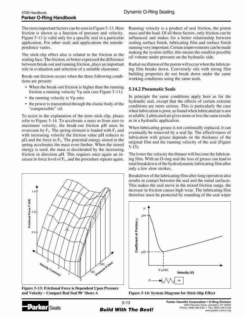
Parker O-Ring Handbook5700 Handbook Dynamic O-Ring Sealing
5-13
Build With The Best!SealsParker Hannifin Corporation • O-Ring Division
2360 Palumbo Drive, Lexington, KY 40509Phone: (859) 269-2351 • Fax: (859) 335-5128
www.parker.com/o-ring
The most important factors can be seen in Figure 5-13. Herefriction is shown as a function of pressure and velocity.Figure 5-13 is valid only for a specific seal in a particularapplication. For other seals and applications the interde-pendence varies.
The stick-slip effect also is related to the friction at thesealing face. The friction, or better expressed the differencebetween break-out and running friction, plays an importantrole in evaluation and selection of a suitable elastomer.
Break-out friction occurs when the three following condi-tions are present:
• When the break-out friction is higher than the runningfriction a running velocity Vµ min (see Figure 5-11);
• the running velocity is Vµ min;• the power is transmitted through the elastic body of the
“compressible” oil.
To assist in the explanation of the term stick-slip, pleaserefer to Figure 5-14. To accelerate a mass m from zero tomaximum velocity, the break-out friction µH must beovercome by F1. The spring element is loaded with F1 andwith increasing velocity the friction value µH reduces toµG and the force to F2. The potential energy stored in thespring accelerates the mass even further. When the storedenergy is used, the mass is decelerated by the increasingfriction in direction µH. This requires once again an in-crease in force level of F1, and the procedure repeats again.
Running velocity is a product of seal friction, the pistonmass and the load. Of all these factors, only friction can beinfluenced and makes for a better relationship betweensealing surface finish, lubricating film and surface finishrunning very important. Certain improvements can be mademaking the system stiffer, this means the smallest possibleoil volume under pressure on the hydraulic side.
Radial oscillation of the piston will occur when the lubricat-ing film breaks down. Conversely oils with strong filmbuilding properties do not break down under the sameworking conditions using the same seals.
5.14.2 Pneumatic Seals
In principle the same conditions apply here as for thehydraulic seal, except that the effects of certain extremeconditions are more serious. This is particularly the casewhen lubrication is poor, as found when lubricated air is notavailable. Lubricated air gives more or less the same resultsas in a hydraulic application.
When lubricating grease is not continually replaced, it caneventually be removed by a seal lip. The effectiveness oflubrication with grease depends on the thickness of theoriginal film and the running velocity of the seal (Figure5-15).
The lower the velocity the thinner will become the lubricat-ing film. With an O-ring seal the loss of grease can lead tototal breakdown of the hydrodynamic lubricating film afteronly a few slow strokes.
Breakdown of the lubricating film after long operation alsoresults in contact between the seal and the metal surfaces.This makes the seal move in the mixed friction range, theincrease in friction causes high wear. The lubricating filmtherefore must be protected by rounding of the seal wiper
Figure 5-14: System Diagram for Stick-Slip Effect
Velocity (V)V min.µ
µ
µH
µGCoe
ffic
ient
of F
rict
ion
µ
F m
Pressure
P(b
ar)Velocity V(m/mm)
Fri
cti
on
al
Fo
rce
F(k
N)
0
100
3
0.5
1.0
1.5
2
1
200
Figure 5-13: Frictional Force is Dependent Upon Pressureand Velocity – Compact Rod Seal 90° Shore A
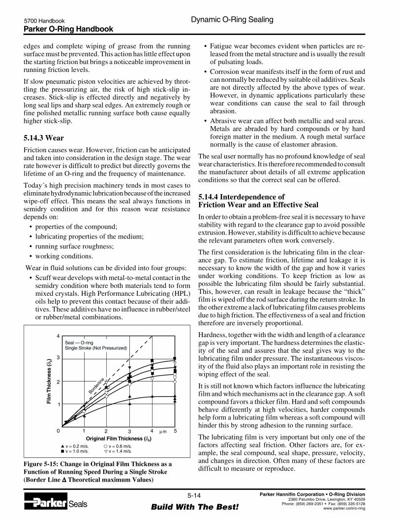
Parker O-Ring Handbook5700 Handbook Dynamic O-Ring Sealing
5-14
Build With The Best!SealsParker Hannifin Corporation • O-Ring Division
2360 Palumbo Drive, Lexington, KY 40509Phone: (859) 269-2351 • Fax: (859) 335-5128
www.parker.com/o-ring
edges and complete wiping of grease from the runningsurface must be prevented. This action has little effect uponthe starting friction but brings a noticeable improvement inrunning friction levels.
If slow pneumatic piston velocities are achieved by throt-tling the pressurizing air, the risk of high stick-slip in-creases. Stick-slip is effected directly and negatively bylong seal lips and sharp seal edges. An extremely rough orfine polished metallic running surface both cause equallyhigher stick-slip.
5.14.3 Wear
Friction causes wear. However, friction can be anticipatedand taken into consideration in the design stage. The wearrate however is difficult to predict but directly governs thelifetime of an O-ring and the frequency of maintenance.
Today´s high precision machinery tends in most cases toeliminate hydrodynamic lubrication because of the increasedwipe-off effect. This means the seal always functions insemidry condition and for this reason wear resistancedepends on:
• properties of the compound;• lubricating properties of the medium;• running surface roughness;• working conditions.
Wear in fluid solutions can be divided into four groups:• Scuff wear develops with metal-to-metal contact in the
semidry condition where both materials tend to formmixed crystals. High Performance Lubricating (HPL)oils help to prevent this contact because of their addi-tives. These additives have no influence in rubber/steelor rubber/metal combinations.
• Fatigue wear becomes evident when particles are re-leased from the metal structure and is usually the resultof pulsating loads.
• Corrosion wear manifests itself in the form of rust andcan normally be reduced by suitable oil additives. Sealsare not directly affected by the above types of wear.However, in dynamic applications particularly thesewear conditions can cause the seal to fail throughabrasion.
• Abrasive wear can affect both metallic and seal areas.Metals are abraded by hard compounds or by hardforeign matter in the medium. A rough metal surfacenormally is the cause of elastomer abrasion.
The seal user normally has no profound knowledge of sealwear characteristics. It is therefore recommended to consultthe manufacturer about details of all extreme applicationconditions so that the correct seal can be offered.
5.14.4 Interdependence ofFriction Wear and an Effective Seal
In order to obtain a problem-free seal it is necessary to havestability with regard to the clearance gap to avoid possibleextrusion. However, stability is difficult to achieve becausethe relevant parameters often work conversely.
The first consideration is the lubricating film in the clear-ance gap. To estimate friction, lifetime and leakage it isnecessary to know the width of the gap and how it variesunder working conditions. To keep friction as low aspossible the lubricating film should be fairly substantial.This, however, can result in leakage because the “thick”film is wiped off the rod surface during the return stroke. Inthe other extreme a lack of lubricating film causes problemsdue to high friction. The effectiveness of a seal and frictiontherefore are inversely proportional.
Hardness, together with the width and length of a clearancegap is very important. The hardness determines the elastic-ity of the seal and assures that the seal gives way to thelubricating film under pressure. The instantaneous viscos-ity of the fluid also plays an important role in resisting thewiping effect of the seal.
It is still not known which factors influence the lubricatingfilm and which mechanisms act in the clearance gap. A softcompound favors a thicker film. Hard and soft compoundsbehave differently at high velocities, harder compoundshelp form a lubricating film whereas a soft compound willhinder this by strong adhesion to the running surface.
The lubricating film is very important but only one of thefactors affecting seal friction. Other factors are, for ex-ample, the seal compound, seal shape, pressure, velocity,and changes in direction. Often many of these factors aredifficult to measure or reproduce.
Figure 5-15: Change in Original Film Thickness as aFunction of Running Speed During a Single Stroke(Border Line ∆∆∆∆∆ Theoretical maximum Values)
Borde
rline
Film
Thic
knes
s (
)δ 2
Original Film Thickness ( )δ0
4
3
2
1
0 1 2 3 4 5
v = 0.2 m/s. v = 0.6 m/s.
µ m
v = 1.4 m/s.v = 1.0 m/s.
Seal — O-ringSingle Stroke (Not Pressurized)

Parker O-Ring Handbook5700 Handbook Dynamic O-Ring Sealing
5-15
Build With The Best!SealsParker Hannifin Corporation • O-Ring Division
2360 Palumbo Drive, Lexington, KY 40509Phone: (859) 269-2351 • Fax: (859) 335-5128
www.parker.com/o-ring
It is therefore quite understandable that seal manufacturerscannot give customers fixed figures regarding friction andwear for an individual seal. Information about seal lifetimesonly can be made when all parameters affecting the seal areknown and reproducible. General assumptions from a fewtests are not acceptable because laboratory tests never canreproduce real working situations.
5.15 Spiral Failure
A unique type of failure sometimes occurs on reciprocatingO-rings which is called spiral failure. This name was givento this type of failure because when it occurs the seal looksas if it had been cut about halfway through the O-ring crosssection in a spiral or corkscrew pattern. Oddly enough, theO-ring usually seals satisfactorily until a complete break orseparation occurs at one place. Sometimes the seal istwisted in two without evidence of the spiral pattern, but ingeneral, the same factors cause the break.
A properly used O-ring slides during all but a small fractionof any reciprocating stroke. This type of seal does notnormally tend to roll or twist because:
1. The hydraulic pressure, acting through the O-ring,produces a greater holding force within the groove(friction on a larger area) than that produced by thesliding surface (rod or cylinder wall) opposite thegroove (see Figure 5-16).
2. The smoother finish of the sliding surface, in rela-tion to the groove surface-finish, produces lessfriction.
3. Running friction is lower than break-out friction.4. The torsional resistance of the O-ring tends to resist
twisting.
The conditions which cause spiral failure are those thatsimultaneously cause segments of the ring to slide andothers to roll. A small amount of twisting is not detrimentalbut, when excessive, torsional failure or spiral failure willoccur. True spiral failure occurs after the seal has beenexcessively twisted, but not broken, and then subjected torelatively high pressure. The twisted seal is forced into thesharp corner at the clearance gap by the pressure which putsan additional stress on this portion of the seal. Rapid stress-aging, or stress above the elastic limit of the rubber, causesa rupture of the O-ring to start adjacent to the clearance gap.Slight flexing, motion, or working of the O-ring apparentlycauses the rupture to penetrate about half way through thecross section. When the O-ring is removed from the gland,it returns to its original shape and the rupture appears as atight spiral around the cross section.
Torsional or spiral failure is not limited to the O-ring ortorus type of seal. Square, delta, four-leaf clover, and othercross sectional shapes (see Figure 5-17) are also prone tofail by twisting if the proper conditions exist.
Figure 5-16: Action of Fluid Pressure to Prevent Rollingof O-ring
FluidPressure
Shaft Small Area
LargeArea
Figure 5-17: Ring Cross-Sections for Reciprocating Seals
O-Ring Square-Ring Delta-RingX-RingAll are subject to torsional or spiral failure.
The design and operational factors which contribute tospiral failure of a seal are listed below in the order of theirrelative importance:
1. Speed of stroke2. Lack of lubrication3. Pressure differential and direction4. Squeeze5. Shape of groove or split grooves6. Temperature of operation7. Length of stroke8. Surface finish of gland9. Type of metal surface10. Side loads11. ID to W ratio of O-ring12. Contamination or gummy deposits on metal surface13. Type of metal rubbing surface14. Breathing15. Concentricity of mating metal parts16. Stretch of O-ring (see rotary shaft seals)17. Lack of back-up rings18. Poor installation of O-rings
Only the very important or less obvious factors whichcontribute to spiral failure will be discussed. Some of thosewhich have been discussed elsewhere will also be omittedhere. It should be remembered that before spiral failure canoccur, an O-ring must be twisted by one or more of theabove inter-related factors. Usually, several factors com-bine to produce any failure that develops. Some of the other

Parker O-Ring Handbook5700 Handbook Dynamic O-Ring Sealing
5-16
Build With The Best!SealsParker Hannifin Corporation • O-Ring Division
2360 Palumbo Drive, Lexington, KY 40509Phone: (859) 269-2351 • Fax: (859) 335-5128
www.parker.com/o-ring
seal designs will leak excessively when twisted. The O-ringusually seals until complete failure occurs.
5.15.1 Speed of Stroke
Investigations have disclosed that one of the primary causesof spiral failure is by reciprocating speeds of less than onefoot per minute. It appears that at this slow speed, the slidingor running seal friction created is very high and comparableto break-out friction. Extreme twisting will occur on low orbalanced pressure components, such as hydraulic accumu-lators, in a relatively few (about 200) cycles if the tempera-ture is above 39°C (100°F). O-ring seals are not recom-mended, therefore, for speeds less than one foot per minutewhen the pressure differential is less than 27.6 Bar (400PSI). If the system pressure is slowly lost, as through slowvalve leaks, and a sealed piston moves slowly through acylinder a number of times, spiral failure of the O-ring veryprobably will result. The obvious remedy here is to providegood maintenance of the system so that slow leaks areprevented, or make it an operational practice to quicklyexhaust the system after the day’s work.
5.15.2 Lack of Lubrication
The lack of lubrication on a surface exposed to the atmo-sphere is one of the prime contributors to spiral failure.Excessive wear will normally occur. However, twisting ofthe seal and spiral failure can result if the unlubricatedsurface is actuated through the seal with little or no pressureon the seal to hold it and prevent it from rolling. This appliesprimarily to long stroke (greater than 152.4 mm (6"))applications.
The remedy for this situation is to:a. Use lubricating (or lubricated) wiper rings.b. Apply a suitable grease, that will not evaporate, to
the exposed surface.c. Use a fluid that will not tend to evaporate or become
tacky at the operating temperature.d. Lubricate metal surface prior to assembly.e. Use a metal or surface plating that will produce less
friction.
5.15.3 Pressure Differential and Direction
As explained earlier, the direction of pressure and sealfriction should oppose each other. Spiral failure is morelikely to occur if the pressure and seal friction are both in thesame direction. In other words, seals in a pump are morelikely to spiral than are those in an actuator.
Normally an O-ring will not twist when the pressure differ-ential across the seal is greater than 27.6 Bar (400 PSI)during operation.
5.15.4 Squeeze
The aerospace industry has generally found that more than0.043 mm (0.017 in.) of squeeze on the side of a 5.3 mm(0.210") cross section (W) O-ring will make some longstroke applications prone to spiral failure. It can be easilyseen that more rolling force is created on the cross sectionwith an increase in squeeze. Other factors are normallyinvolved when failure occurs with the standard squeezesrecommended for reciprocating seals.
5.15.5 Shape of Groove and Split Groove
If a V-shaped groove is used, it is evident that the hydraulicholding force is reduced because the area on the side of theV-groove is less than at the bottom and side of a squaregroove. V-grooves are much more prone to produce spiralfailures. This is especially true if any of the other factors areout of balance. Split grooves give trouble if the hydraulicholding force on the O-ring against both the side and thebottom of the groove is not maintained. Great care shouldbe used when designing glands which have an opening inthe bottom in order to make sure the normal holding forcewill be maintained (see Figure 5-16).
5.15.6 Temperature of Operation
When the temperature in and around a system is substan-tially increased, the seals are more prone to fail. This isbecause lubricants are more likely to evaporate, or losetheir, “light ends”, and/or lose some of their lubricity, theseal becomes softer, the squeeze is increased due to therubber expansion, and the metal clearances may becomegreater.
5.15.7 Length of Stroke
As a general rule, the longer the stroke of a cylinder or rod,the greater the eccentricity, bending, side load, and otherfactors that contribute to wear and/or spiral failure. We donot recommend an O-ring for service when the stroke isgreater than 304.8 mm (12") unless extra precautions aretaken to avoid trouble.
5.15.8 Surface Finish
When a cylinder or rod is actuated, side loads, bending,chips or other foreign material, and non perfect machining,drilling and finishing all in some way tend to contribute toscoring, galling, marring, or scratching of the surface overwhich the seal must slide (refer to metals and floatingglands). When this occurs, the roughness is unevenly dis-tributed around the circumference or periphery. Even thoughit may be very slight, it creates an uneven friction conditionand thus can contribute to spiral failure and/or uneven,excessive wear.

Parker O-Ring Handbook5700 Handbook Dynamic O-Ring Sealing
5-17
Build With The Best!SealsParker Hannifin Corporation • O-Ring Division
2360 Palumbo Drive, Lexington, KY 40509Phone: (859) 269-2351 • Fax: (859) 335-5128
www.parker.com/o-ring
5.15.9 Back-Up Rings
Back-up rings sometimes provide enough extra lubricationon the return stroke to assist in the prevention of spiralfailure. For further information see the discussion on back-up rings in Section VI.
5.16 Modifications for Special Applications
Normally, the gland dimensions given in Design Tables 5-1and 5-2 are adequate and give trouble-free service. If notapplicable, the following modifications will help solvespecific problems:
• Small Amount of Leakage• Early Stress-Aging• Low Temperature Leakage• Excessive Swells (above 20%)
5.16.1 Small Amount of Leakage1. Examine the O-ring for signs of cutting during
installation.2. Increase the squeeze on the cross-section of O-ring.3. Reduce the groove length. A wide groove may cause
leakage because of pumping action of the O-ring.This is especially possible when the piston is cycledrapidly.
4. Improve the surface finish of metal rubbing surface.5. Check for eccentric machining of gland.
5.16.2 Early Stress-Aging1. Redesign groove to reduce stretch of the O-ring.2. Redesign groove to reduce squeeze of the O-ring.3. Use a more heat-resistant rubber compound.4. Make certain O-ring is not being twisted during dry
assembly.5. Use larger O-ring to reduce stretch.6. Make sure O-rings are not closer than six feet from
an electric motor (operating) during shelf storage.Ozone causes rapid deterioration of most elastomers.
5.16.3 Low Temperature Leakage1. Make certain that O-ring compound was designed
for operation at low temperatures.2. Increase squeeze of the O-ring. Coefficient of con-
traction of rubber is about 10 times that of steel andseveral times greater than aluminum.
3. Spring load the O-ring (see Figure 3-1).4. Make sure all gland surfaces are smooth enough (see
paragraph 5.3).
Note: Minute leakage is to be expected and is in fact,desirable, when an O-ring is used as a reciprocating seal. AnO-ring that does not by-pass a little fluid at each stroke isrunning dry and high friction and rapid seal wear will result.
5.16.4 Excessive Swell (above 20%)1. Replace O-ring with one made from a compound
more resistant to the fluid being sealed.2. Increase groove length. If the volume of the groove
is too small, increased friction and excessive stressmay cause premature failure of the O-ring (refer todiscussions of friction and spiral failure).
5.17 Gland Dimensions forReciprocating Hydraulic O-Ring Seals
For most reciprocating applications in which an O-ring issealing a liquid of any kind (the design is not limited tohydraulic oils), the dimensions of either Design Table 5-1,the military design, or Design Table 5-2, the industrialdesign, would be suitable. Of the two, Parker Seal Groupnormally recommends the Table 5-2 dimensions becausethese industrial designs, in most cases, allow for the use ofstandard drill rod sizes and standard boring tools. Thedimensions in this table are actually in good agreement withearly versions of the aerospace table. The military dimen-sions cause less stretch on the O-rings. The percent reduc-tion is so slight, except in the smallest sizes, that the effectcannot be significant, while the cost of the special machinedrods and boring tools that are required could be high.
In reciprocating applications for which neither table appliesbecause of a predetermined dimension that does not agree,the following procedure may be used to find gland dimen-sions.
1. For piston seals, select an O-ring having an OD nearto or preferably slightly larger than the cylinder borediameter.
2. For rod seals, select on O-ring having an ID closestto the rod diameter. It may be slightly larger orsmaller, but ID stretch should not exceed 5% asinstalled for optimum design.
3. In all reciprocating seals, make sure minimumsqueeze recommendations are considered.
5.18 Floating Glands
Since it is impossible to bore, drill or tap perfect, true holes,and to machine perfect parts providing perfect alignment,the engineer should consider the floating gland. Eccentric-ity (lack of concentricity) is allowable, but it does causehigh unit loads on small portions of bearing surfaces. Inturn, this causes minute scratches on the metal surface onwhich the O-ring must rub (with the possible exception ofvery soft bearing materials, such as babbitt).

Parker O-Ring Handbook5700 Handbook Dynamic O-Ring Sealing
5-18
Build With The Best!SealsParker Hannifin Corporation • O-Ring Division
2360 Palumbo Drive, Lexington, KY 40509Phone: (859) 269-2351 • Fax: (859) 335-5128
www.parker.com/o-ring
In order to reduce or eliminate the high bearing loads, therelatively inexpensive floating gland should be used when-ever possible. The object of this gland is to allow the pistonor rod bearing (containing the O-ring groove), to pivot,adjust, or float a small amount, offsetting misalignment.(See Figure 5-18.)
This gland design increases the life of the O-ring andeliminates many of the spasmodic or unscheduled failures,as well as reducing the maintenance cost.
5.19 Pneumatic Reciprocating O-Ring Seals
The past few years have shown a rapid increase of interestin pneumatic systems, not only for new equipment, but asa replacement for some existing hydraulic components.Some of the more general reasons are:
1. Increased non-flammability.2. Light weight.3. Leakage is less critical and does not contaminate the
surrounding area.4. The atmosphere acts as a giant reservoir.5. System fluid is not decomposed by high tempera-
ture.
5.20 Temperature
Nitrile rubber is generally the first compound consideredfor a seal. It should be remembered, however, that it is lessresistant to dry heat than it is to hot oils or other liquids.Nitrile compounds are used for pneumatic applicationsmore than any other polymer, but in this kind of use,temperatures are usually low. In pneumatic applicationsabove 104°C (220°F) for extended periods of time, con-sider ethylene propylene, fluorocarbon, or even silicone orfluorosilicone. The choice depends on temperature ex-tremes, internal lubricant, severity of service, and overallcost.
5.21 Silicone Compounds
If silicone compounds are used, extra attention is necessaryto make sure that all foreign material and sharp edges or
corners are removed from the gland. This is necessarybecause of the relatively poor resistance to cutting andabrasion which is characteristic of silicone compounds.Recent developments have improved the abrasion resis-tance and oil resistance of the silicones, but they are still farshort of many other synthetic rubbers.
5.22 High-Pressure
The most difficult gland to seal for any type of packing isthat in a high-pressure pneumatic system because, in addi-tion to the problems encountered with liquids, the follow-ing must be considered:
1. It is the hardest type seal to keep lubricated.2. Oxygen in the air comes in direct contact with the
seal and causes rapid aging and/or deterioration.This problem is amplified as system pressures andtemperatures increase. (More oxygen is present dueto the compression of the air.)
3. Gaseous molecules are very small, and will pass intoand through (permeate) materials and openings whichliquids will not. (See Table 3-19.)
4. The large change in volume which a gas undergoeswith fluctuations in pressure often make necessaryvery special rubber seal materials so gases that haveentered the seal can be rapidly expelled. Otherwise,blisters, ruptures, and chunks will be blown out ofthe seal when decompression of the system occurs.All organic materials are permeable, so the gascannot be kept out of the seal.
5. Compounds other than those used in hydraulic sys-tems are often necessary because the requirementsare entirely different. This is especially true at hightemperatures above 71°C (160°F) and high pressure(69 Bar to 207 Bar) (1000 PSI to 3000 PSI).
5.23 Lubrication
Most conventional pneumatic applications that fail prema-turely do so because of inadequate lubrication. Rubber hasan inherently high coefficient of friction with all metals andmost non-metallic surfaces. Disregarding the necessity forlubrication will result in high friction, excessive abrasion orrapid wear of the rubber O-ring and heat build-up. Forpneumatic seal applications it is especially important thatadequate lubrication be provided. Of course, a lubricantmust be selected that will not cause deterioration of theO-ring.
5.24 Gland Dimensions
Normally, the static and reciprocating gland dimensionsgiven at the end of the Static Seals section and this sectionare adequate and give trouble-free pneumatic service. Muchlower squeeze designs are permissible and used frequentlyin low pressure pneumatic applications (i.e. using shop airFigure 5-18: Floating Gland
Washer must betight againstshaft shoulder
E2 Snap
Ring
Clearance: X = 0.003 to 0.006 in.To prevent extrusion
2 refer to Figure 3-2or Table 5-1 or 5-2
E
X X
X
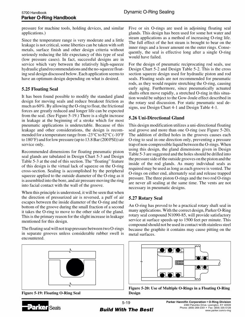
Parker O-Ring Handbook5700 Handbook Dynamic O-Ring Sealing
5-19
Build With The Best!SealsParker Hannifin Corporation • O-Ring Division
2360 Palumbo Drive, Lexington, KY 40509Phone: (859) 269-2351 • Fax: (859) 335-5128
www.parker.com/o-ring
pressure for machine tools, holding devices, and similarapplications.)
Since the temperature range is very moderate and a littleleakage is not critical, some liberties can be taken with softmetals, surface finish and other design criteria withoutseriously reducing the life expectancy of this type of seal(low pressure cases). In fact, successful designs are inservice which vary between the relatively high-squeezehydraulic gland recommendations and the no-squeeze float-ing seal design discussed below. Each application seems tohave an optimum design depending on what is desired.
5.25 Floating Seal
It has been found possible to modify the standard glanddesign for moving seals and reduce breakout friction asmuch as 60%. By allowing the O-ring to float, the frictionalforces are greatly reduced and longer life can be expectedfrom the seal. (See Figure 5-19.) There is a slight increasein leakage at the beginning of a stroke which for mostpneumatic applications is undetectable. Because of thisleakage and other considerations, the design is recom-mended for a temperature range from -23°C to 82°C (-10°Fto 180°F) and for low pressure (up to 13.8 Bar (200 PSI)) airservice only.
Recommended dimensions for floating pneumatic pistonseal glands are tabulated in Design Chart 5-3 and DesignTable 5-3 at the end of this section. The “floating” featureof this design is the virtual lack of squeeze on the O-ringcross-section. Sealing is accomplished by the peripheralsqueeze applied to the outside diameter of the O-ring as itis assembled into the bore, and air pressure moving the ringinto facial contact with the wall of the groove.
When this principle is understood, it will be seen that whenthe direction of pressurized air is reversed, a puff of airescapes between the inside diameter of the O-ring and thebottom of the groove during the small fraction of a secondit takes the O-ring to move to the other side of the gland.This is the primary reason for the slight increase in leakagementioned for this design.
The floating seal will not trap pressure between two O-ringsin separate grooves unless considerable rubber swell isencountered.
Five or six O-rings are used in adjoining floating sealglands. This design has been used for some hot water andsteam applications as a method of increasing O-ring life.The full effect of the hot steam is brought to bear on theinner rings and a lesser amount on the outer rings. Conse-quently, the seal is effective long after a single O-ringwould have failed.
For the design of pneumatic reciprocating rod seals, useDesign Chart 5-2 and Design Table 5-2. This is the crosssection squeeze design used for hydraulic piston and rodseals. Floating seals are not recommended for pneumaticrods, as they would require stretching the O-ring, causingearly aging. Furthermore, since pneumatically actuatedshafts often move rapidly, a stretched O-ring in this situa-tion would be subject to the Gow-Joule effect described inthe rotary seal discussion. For static pneumatic seal de-signs, use Design Chart 4-1 and Design Table 4-1.
5.26 Uni-Directional Gland
This design modification utilizes a uni-directional floatingseal groove and more than one O-ring (see Figure 5-20).The addition of drilled holes in the grooves causes eachO-ring to seal in one direction only, preventing a pressuretrap of non-compressible liquid between the O-rings. Whenusing this design, the gland dimensions given in DesignTable 5-3 are suggested and the holes should be drilled intothe pressure side of the outside grooves on the piston and theinside of the rod glands. As many individual seals asrequired may be used as long as each groove is vented. TheO-rings on either end, alternately seal and release trappedpressure. The three piston O-rings and the two rod O-ringsare never all sealing at the same time. The vents are notnecessary in pneumatic designs.
5.27 Rotary Seal
An O-ring has proved to be a practical rotary shaft seal inmany applications. With the correct design, Parker O-Ringrotary seal compound N1090-85, will provide satisfactoryservice at surface speeds up to 1500 feet per minute. Thiscompound should not be used in contact with stainless steelbecause the graphite it contains may cause pitting on themetal surfaces.
Figure 5-20: Use of Multiple O-Rings in a Floating O-RingDesignFigure 5-19: Floating O-Ring Seal

Parker O-Ring Handbook5700 Handbook Dynamic O-Ring Sealing
5-20
Build With The Best!SealsParker Hannifin Corporation • O-Ring Division
2360 Palumbo Drive, Lexington, KY 40509Phone: (859) 269-2351 • Fax: (859) 335-5128
www.parker.com/o-ring
The design conditions are most critical for rotary seals, aswould be expected. Relatively high durometer compounds,close control of tolerances, and minimum cross section arerequired.
Rotary seals usually should not be used at temperaturesbelow -40°C (-40°F) even though flexibility to -54°C(-65°F) is claimed, since thermal shrinkage and loss ofresilience tend to cause loss of contact with the shaft. Insome cases, initial leakage of frozen seals may be tolerableuntil heat build-up occurs in higher speed shafts. Springloading may be helpful in some situations.
High-speed shafts of soft metal should be avoided sincethey will normally wear more rapidly than the rubber,opening the clearance and allowing leakage. Hardenedsteel shafts in the range of 55 Rockwell are desirable, butnot mandatory. Attention to clearances, side thrust, andend-play are critical in designing effective rotary O-ringseals.
Whenever it can be avoided, an O-ring should not beinstalled in a gland that holds it in more than a minimum oftensional stress. This principle is especially important toconsider when designing for an O-ring rotary shaft seal.Most elastomers when heated in the stressed, or stretchedcondition will contract. This is of practical importance in arotary seal because it results in a tendency for the O-ring toseize the high-speed rotating shaft. This phenomenon,known as the Gow-Joule effect, occurs only if the rubber isunder tensile stress.
The friction between the O-ring and the rotating shaftcreates heat. When it is installed in more than a minimumof tensional stress, the O-ring tends to contract when heatedand seize the high speed rotating shaft. This contractioncauses more friction which in turn causes more heat and theprocess becomes self-perpetuating, until the O-ring is de-stroyed.
Even at low surface speeds, where heating is not a problem,a stretched O-ring tends to rotate with the shaft and leak. Forspeeds below 200 feet per minute, the squeeze recom-mended in Design Chart 5-2 may be used. However, theshaft diameter should be no larger than the free state ID ofthe O-ring.
Shaft seal applications where the O-ring is installed in agroove in the shaft are not recommended if the shaft rotates.This is due to the centrifugal action which causes the O-ringto rotate and rub on all surfaces which generally causesearly seal leakage or failure.
The use of O-rings as high speed rotary shaft seals is usuallynot recommended for applications requiring lower than-40°C (-40°F) or higher than 121°C (250°F) operatingtemperatures.
The O-ring gland in a rotary shaft application should not beused as a bearing surface. The shaft should be contained by
bearings that will permit the O-ring to operate under thelowest possible heat and load. Because of the limitedinterference that must be used to avoid frictional heat,the O-ring will not compensate for shafts that are out ofround or rotate eccentrically. Shafts should remain concen-tric within .013 mm (0.0005") T.I.R.
Bearings of all types cause considerable local heat and sealsplaced too close to them will fail prematurely.
Provision should be made for the dissipation of any heatthat may be generated because of friction. The nearer toroom temperature the seal interface, the longer the O-ringwill seal. There are two methods commonly used to preventhigh bearing heat build-up:
Preferred: Provide a clearance of 0.203 mm (0.008") on aside between the rotating shaft and the O-ring housing.Make sure that the shaft does not rub the housing. Forpressures exceeding 55.2 Bar (800 PSI), decrease the dia-metrical clearance per Figure 3-2.
Alternate: The bearing length should be at least 10 times the“W” dimension of the O-ring used. This provides for agreater area for heat transfer. If the clearance must be keptto a minimum to prevent high pressure extrusion, the 10times “W” rule also applies. A floating gland (see Figure5-18) is preferred to avoid high unit load at a local point orarea.
Experience has proven that it is desirable to use the O-ringwith the smallest “W”, or cross-section diameter, availablefor the ID required. It is recommended that a “W” dimen-sion of 0.103 be considered maximum for all speeds over600 feet per minute. (See Table 5-5.)
All metals and plastics suitable for the housing or glandconstruction of seal assemblies requiring rotary shaft sealscan be used with O-rings. However, since most rotary sealcompounds contain graphite as a compound ingredient, anymetal, such as stainless steel, or surface treatment that maybe adversely affected by this material should be avoided.
To insure maximum O-ring life, use an O-ring compoundthat has been specially developed for rotary seal applica-tions and provides the required characteristics that arenecessary for this service. See Section II, Basic O-Ring
O-Ring Sections for Rotary Seals
Speed Maximum Recommended(fpm*) “W” Dimension
0 to 200 Usually not critical (Use chart 5-2)200 to 400 0.139200 to 600 0.103
200 to 1500 0.070
*Feet per minute = 0.26 X Shaft Diameter (inches) X rpm
Table 5-5: O-Ring Sections for Rotary Seals
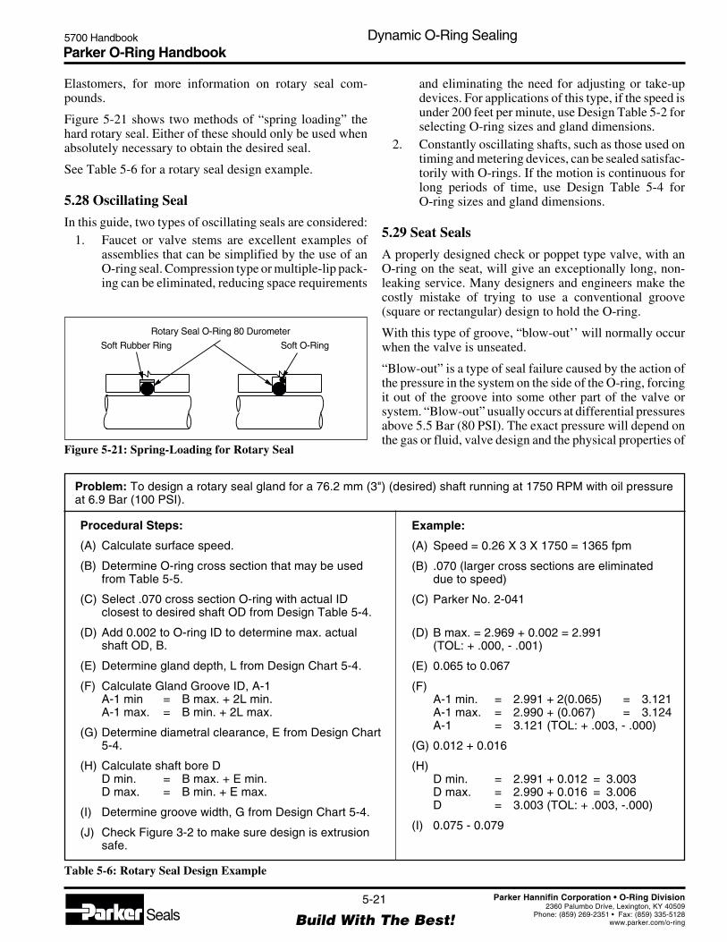
Parker O-Ring Handbook5700 Handbook Dynamic O-Ring Sealing
5-21
Build With The Best!SealsParker Hannifin Corporation • O-Ring Division
2360 Palumbo Drive, Lexington, KY 40509Phone: (859) 269-2351 • Fax: (859) 335-5128
www.parker.com/o-ring
Elastomers, for more information on rotary seal com-pounds.
Figure 5-21 shows two methods of “spring loading” thehard rotary seal. Either of these should only be used whenabsolutely necessary to obtain the desired seal.
See Table 5-6 for a rotary seal design example.
5.28 Oscillating Seal
In this guide, two types of oscillating seals are considered:1. Faucet or valve stems are excellent examples of
assemblies that can be simplified by the use of anO-ring seal. Compression type or multiple-lip pack-ing can be eliminated, reducing space requirements
Figure 5-21: Spring-Loading for Rotary Seal
Soft Rubber Ring
Rotary Seal O-Ring 80 Durometer
Soft O-Ring
and eliminating the need for adjusting or take-updevices. For applications of this type, if the speed isunder 200 feet per minute, use Design Table 5-2 forselecting O-ring sizes and gland dimensions.
2. Constantly oscillating shafts, such as those used ontiming and metering devices, can be sealed satisfac-torily with O-rings. If the motion is continuous forlong periods of time, use Design Table 5-4 forO-ring sizes and gland dimensions.
5.29 Seat Seals
A properly designed check or poppet type valve, with anO-ring on the seat, will give an exceptionally long, non-leaking service. Many designers and engineers make thecostly mistake of trying to use a conventional groove(square or rectangular) design to hold the O-ring.
With this type of groove, “blow-out’’ will normally occurwhen the valve is unseated.
“Blow-out” is a type of seal failure caused by the action ofthe pressure in the system on the side of the O-ring, forcingit out of the groove into some other part of the valve orsystem. “Blow-out” usually occurs at differential pressuresabove 5.5 Bar (80 PSI). The exact pressure will depend onthe gas or fluid, valve design and the physical properties of
Problem: To design a rotary seal gland for a 76.2 mm (3") (desired) shaft running at 1750 RPM with oil pressureat 6.9 Bar (100 PSI).
Procedural Steps:
(A) Calculate surface speed.
(B) Determine O-ring cross section that may be usedfrom Table 5-5.
(C) Select .070 cross section O-ring with actual IDclosest to desired shaft OD from Design Table 5-4.
(D) Add 0.002 to O-ring ID to determine max. actualshaft OD, B.
(E) Determine gland depth, L from Design Chart 5-4.
(F) Calculate Gland Groove ID, A-1A-1 min = B max. + 2L min.A-1 max. = B min. + 2L max.
(G) Determine diametral clearance, E from Design Chart5-4.
(H) Calculate shaft bore DD min. = B max. + E min.D max. = B min. + E max.
(I) Determine groove width, G from Design Chart 5-4.
(J) Check Figure 3-2 to make sure design is extrusionsafe.
Example:
(A) Speed = 0.26 X 3 X 1750 = 1365 fpm
(B) .070 (larger cross sections are eliminateddue to speed)
(C) Parker No. 2-041
(D) B max. = 2.969 + 0.002 = 2.991(TOL: + .000, - .001)
(E) 0.065 to 0.067
(F)A-1 min. = 2.991 + 2(0.065) = 3.121A-1 max. = 2.990 + (0.067) = 3.124A-1 = 3.121 (TOL: + .003, - .000)
(G) 0.012 + 0.016
(H)D min. = 2.991 + 0.012 = 3.003D max. = 2.990 + 0.016 = 3.006D = 3.003 (TOL: + .003, -.000)
(I) 0.075 - 0.079
Table 5-6: Rotary Seal Design Example

Parker O-Ring Handbook5700 Handbook Dynamic O-Ring Sealing
5-22
Build With The Best!SealsParker Hannifin Corporation • O-Ring Division
2360 Palumbo Drive, Lexington, KY 40509Phone: (859) 269-2351 • Fax: (859) 335-5128
www.parker.com/o-ring
Figure 5-24: Groove Designs to Prevent Blow-Out
O-Ring
O-Ring
Pressure
the O-ring when a non-retaining or conventional typegroove is used.
It should be kept in mind that blow-out is similar toextrusion, but that it occurs at considerably lower pressures.
Figure 5-22 shows an O-ring on the seat of a check valve ina conventional groove. The seal is satisfactory as long as thevalve is not opened at or near the pressure necessary tocause blow-out.
Figure 5-23 illustrates a valve opening above “blow-out”pressure. As the valve opens, the space between the twofaces becomes increasingly larger. The pressure openingthe valve is also acting on the O-ring, causing it to continueto seal the opening until it is stretched completely out of thegroove and is blown out or forced into another part of thesystem.
Gases such as air, LPG, CO2, etc. enter or permeate the
O-ring. With release of pressure, the gas inside the O-ring
Figure 5-22: Valve Seat Seal, Standard Groove
O-Ring
Pressure
O-Ring
Pressure
Figure 5-23: O-Ring Blow-Out, Standard Groove
can cause the seal to “balloon” or swell momentarily. (Theamount depends on the pressure.) The ballooning effectthat can occur at very low pressure usually pops the O-ringout of the groove the same as blow-out. “Ballooning” and“blow-out” often combine to cause valve seal failure.Another term often used to describe this phenomenon is“explosive decompression.” O-ring blow-out may be pre-vented by using a groove design which encloses more than180° of the O-ring cross section or by venting the groove.Typical methods used are shown in Figure 5-24. If arectangular groove must be used, alter the dimensions asfollows:
Groove depth — 0.015 to 0.025 less than O-ringcross section diameter.
Groove width — 1.00 to 1.10 times the O-ringcross section diameter.
Groove side angle — 0°, if possible.

Parker O-Ring Handbook5700 Handbook Dynamic O-Ring Sealing
5-23
Build With The Best!SealsParker Hannifin Corporation • O-Ring Division
2360 Palumbo Drive, Lexington, KY 40509Phone: (859) 269-2351 • Fax: (859) 335-5128
www.parker.com/o-ring
Guide For Design Table 5-1
Select Closest ReadIf Desired Dimension Dimension Horizontally To Determine
Is Known For In Column In Column Dimension For
Cylinder Bore G Groove Width*or Male Gland A C Piston or Cylinder O.D.Cylinder Bore I.D F Groove O.D.
G Groove Width*Piston or A Cylinder Bore or Male GlandCylinder O.D. C Cylinder Bore I.D.
F Groove O.D.
G Groove Width*Rod or Gland J Groove I.D.Sleeve O.D. B H Rod Bore or Female Gland
Housing Bore I.D.
Rod Bore or H G Groove Width*Female Gland J Groove I.D.Housing Bore I.D. B Rod or Gland Sleeve O.D.
*For information on groove width refer to Design Chart 5-1A
Design Guide 5-1: Guide For Design Chart 5-1
After selecting gland dimension, read horizontally to determine proper O-ring size number perAS568A.
There are a number of various O-ring gland design specifications in use throughout industry. Theseinclude Aerospace Recommended Practice (ARP) 1232, 1233 and 1234. There also is theInternational Standards Organization (better known as ISO) Specification 3601/2. Each of theseand other less accepted documents have slight dimensional variations from those found in thisHandbook.
5.30 O-Ring Glands
5.30.1 O-Ring Glands (Per SAE AS4716) For Aerospace Hydraulic(Static And Reciprocating) Packings And Gaskets
Design Chart 5-1 provides the basis for calculating gland dimensions for standard O-ring sizes.These dimensions have been calculated and are listed in Design Table 5-1. The procedures for theuse of Design Table 5-1 are outlined in Design Guide 5-1.

Parker O-Ring Handbook5700 Handbook Dynamic O-Ring Sealing
5-24
Build With The Best!SealsParker Hannifin Corporation • O-Ring Division
2360 Palumbo Drive, Lexington, KY 40509Phone: (859) 269-2351 • Fax: (859) 335-5128
www.parker.com/o-ring
Design Chart 5-1A For Gland Design, O-Ring and Other Elastomeric Seals (SAE AS4716)Standard Gland Width for Zero, One, and Two Backup Rings
Gland O-ring Cross Section Gland Width G Gland Width G Gland Width Gand W No Backup Ring One Backup Ring Two Backup Rings
AS568Dash
Number Min. Max. Min. Max. Min. Max. Min. Max.
001 .037 .043 .070 .075 — — — —002 .047 .053 .077 .082 — — — —003 .057 .063 .088 .093 — — — —
004 to 009 .067 .073 .098 .103 .154 .164 .210 .220010 to 028 .067 .073 .094 .099 .150 .160 .207 .217110 to 149 .100 .106 .141 .151 .183 .193 .245 .255210 to 247 .135 .143 .188 .198 .235 .245 .304 .314325 to 349 .205 .215 .281 .291 .334 .344 .424 .434424 to 460 .269 .281 .375 .385 .475 .485 .579 .589
Design Chart 5-1A: Gland Design, O-Ring and Other Elastomeric Seals (SAE AS4716)
Design Chart 5-1B For Gland Design, O-Ring andOther Elastomeric Seals (SAE AS4716)
Standard Gland Diametral Clearance DimensionsGland O-ring Cross Section Diametral Clearanceand W E Max.
AS568Dash
Number Min. Max. Exterior Interior
001 .037 .043 .004 .004002 .047 .053 .004 .004003 .057 .063 .004 .004
004 to 012 .067 .073 .004 .004013 to 028 .067 .073 .005 .005110 to 126 .100 .106 .005 .005127 to 129 .100 .106 .005 .006130 to 132 .100 .106 .006 .006133 to 140 .100 .106 .006 .007141 to 149 .100 .106 .007 .007210 to 222 .135 .143 .005 .005223 and 224 .135 .143 .006 .006225 to 227 .135 .143 .006 .007228 to 243 .135 .143 .007 .007244 and 245 .135 .143 .008 .007246 and 247 .135 .143 .008 .008325 to 327 .205 .215 .006 .006328 and 329 .205 .215 .006 .007330 to 345 .205 .215 .007 .007346 to 349 .205 .215 .008 .007425 to 438 .269 .281 .009 .009439 to 445 .269 .281 .009 .010
446 .269 .281 .010 .010447 to 460 .269 .281 .011 .010
Design Chart 5-1B: Gland Design, O-Ring and Other ElastomericSeals (SAE AS4716)

Parker O-Ring Handbook5700 Handbook Dynamic O-Ring Sealing
5-25
Build With The Best!SealsParker Hannifin Corporation • O-Ring Division
2360 Palumbo Drive, Lexington, KY 40509Phone: (859) 269-2351 • Fax: (859) 335-5128
www.parker.com/o-ring
Gland Detail
X: Dynamic Seals ..................... 32Static Seals .......................... 63
Y: Dynamic SealsNo Back-Up Ring ................ 32Static Seals or DynamicSeals with Back-Up Ring .... 63
1/2 E 1/2 E 1/2E
H Dia.J Dia.
F Dia.C Dia.
A Dia.
F Piston Groove Dia.C Piston O.D.
A Cylinder Bore Dia.B Rod O.D.
H Rod Bore Dia.
1/2 E
L
G
R
16
Y
X
Y
0° to 5°(Typ.) +.005
Break Edge .005 — .000
J Rod GlandGroove I.D
NoBack-up
Ring
OneBack-up
Ring
Pressure Pressure Pressure
TwoBack-upRings
GG G
B Dia.
Finishes are RMS valuesGlandDepth
GrooveDepth (Ref.)
Design Table 5-1 — Gland Design, O-Ring and Other Elastomeric Seals (SAE AS4716)
Groove Wall Angle (X)
Pressure (PSIG) X (Degrees)
≤ 3000 0.0 +5.0/-0.0
4000 to 6000 0.0 +2.0/-0.0
>6000 to 8000 0.0 ±0.5
Break Edge
Pressure (PSIG) Groove Edge Break
≤ 4000 0.005 +0.005/-0.000
> 4000 0.002 +0.008/-0.000
Gland Piston Rod orand or Cylinder Gland Rod Actual Actual
AS568 Cylinder Bore Gland Sleeve Bore Gland Minimum Squeeze Maximum SqueezeDash OD ID OD OD ID IDNo. C A F B H J Piston Rod Piston Rod
Design Table 5-1: Gland Design, O-Ring and Other Elastomeric Seals (SAE AS4716)
001 0.093 0.095 0.033 0.033 0.035 0.095 0.0000 – 0.0145 –0.092 0.096 0.032 0.032 0.036 0.096 – 0.0000 – 0.0145
002 0.126 0.128 0.048 0.048 0.050 0.128 0.0000 – 0.0139 –0.125 0.129 0.047 0.047 0.051 0.129 – 0.0000 – 0.0139
003 0.157 0.159 0.063 0.063 0.065 0.159 0.0000 – 0.0154 –0.156 0.160 0.062 0.062 0.066 0.160 – 0.0000 – 0.0154
004 0.188 0.190 0.076 0.076 0.078 0.190 0.0003 – 0.0176 –0.187 0.191 0.075 0.075 0.079 0.191 – 0.0003 – 0.0176
005 0.219 0.221 0.108 0.108 0.110 0.221 0.0020 – 0.0178 –0.218 0.222 0.107 0.107 0.111 0.222 – 0.0020 – 0.0178
006 0.233 0.235 0.123 0.123 0.125 0.235 0.0023 – 0.0177 –0.232 0.236 0.122 0.122 0.126 0.236 – 0.0023 – 0.0177
007 0.264 0.266 0.154 0.154 0.156 0.266 0.0032 – 0.0179 –0.263 0.267 0.153 0.153 0.157 0.267 – 0.0032 – 0.0179
008 0.295 0.297 0.189 0.185 0.187 0.294 0.0050 – 0.0193 –0.294 0.298 0.188 0.184 0.188 0.295 – 0.0053 – 0.0196
009 0.327 0.329 0.220 0.217 0.219 0.327 0.0052 – 0.0192 –0.326 0.330 0.219 0.216 0.220 0.328 – 0.0052 – 0.0193
010 0.358 0.360 0.250 0.248 0.250 0.359 0.0052 – 0.0190 –0.357 0.361 0.249 0.247 0.251 0.360 – 0.0050 – 0.0189
011 0.420 0.422 0.312 0.310 0.312 0.421 0.0057 – 0.0193 –0.419 0.423 0.311 0.309 0.313 0.422 – 0.0054 – 0.0191
012 0.483 0.485 0.375 0.373 0.375 0.484 0.0060 – 0.0194 –0.482 0.486 0.374 0.372 0.376 0.485 – 0.0057 – 0.0192
013 0.548 0.550 0.441 0.435 0.437 0.545 0.0050 – 0.0196 –0.547 0.552 0.439 0.433 0.438 0.547 – 0.0050 – 0.0198

Parker O-Ring Handbook5700 Handbook Dynamic O-Ring Sealing
5-26
Build With The Best!SealsParker Hannifin Corporation • O-Ring Division
2360 Palumbo Drive, Lexington, KY 40509Phone: (859) 269-2351 • Fax: (859) 335-5128
www.parker.com/o-ring
Gland Piston Rod orand or Cylinder Gland Rod Actual Actual
AS568 Cylinder Bore Gland Sleeve Bore Gland Minimum Squeeze Maximum SqueezeDash OD ID OD OD ID IDNo. C A F B H J Piston Rod Piston Rod
Design Table 5-1 — Gland Design, O-Ring and Other Elastomeric Seals (SAE AS4716) (Continued)
Design Table 5-1: Gland Design, O-Ring and Other Elastomeric Seals (SAE AS4716)
014 0.611 0.613 0.504 0.498 0.500 0.608 0.0052 – 0.0197 –0.610 0.615 0.502 0.496 0.501 0.610 – 0.0051 – 0.0199
015 0.673 0.675 0.566 0.560 0.562 0.670 0.0052 – 0.0200 –0.672 0.677 0.564 0.558 0.563 0.672 – 0.0051 – 0.0202
016 0.736 0.738 0.629 0.623 0.625 0.733 0.0052 – 0.0203 –0.735 0.740 0.627 0.621 0.626 0.735 – 0.0051 – 0.0205
017 0.798 0.800 0.691 0.685 0.687 0.795 0.0054 – 0.0204 –0.797 0.802 0.689 0.683 0.688 0.797 – 0.0052 – 0.0205
018 0.861 0.863 0.753 0.748 0.750 0.858 0.0050 – 0.0200 –0.860 0.865 0.751 0.746 0.751 0.860 – 0.0053 – 0.0205
019 0.923 0.925 0.815 0.810 0.812 0.920 0.0051 – 0.0200 –0.922 0.927 0.813 0.808 0.813 0.922 – 0.0053 – 0.0205
020 0.989 0.991 0.881 0.873 0.875 0.983 0.0050 – 0.0198 –0.988 0.993 0.879 0.871 0.876 0.985 – 0.0054 – 0.0205
021 1.051 1.053 0.943 0.935 0.937 1.045 0.0051 – 0.0199 –1.050 1.055 0.941 0.933 0.938 1.047 – 0.0055 – 0.0205
022 1.114 1.116 1.006 0.998 1.000 1.108 0.0051 – 0.0200 –1.113 1.118 1.004 0.996 1.001 1.110 – 0.0055 – 0.0205
023 1.176 1.178 1.068 1.060 1.062 1.170 0.0052 – 0.0200 –1.175 1.180 1.066 1.058 1.063 1.172 – 0.0055 – 0.0205
024 1.239 1.241 1.131 1.123 1.125 1.233 0.0052 – 0.0200 –1.238 1.243 1.129 1.121 1.126 1.235 – 0.0056 – 0.0205
025 1.301 1.303 1.193 1.185 1.187 1.295 0.0052 – 0.0201 –1.300 1.305 1.191 1.183 1.188 1.297 – 0.0056 – 0.0205
026 1.384 1.366 1.256 1.248 1.250 1.358 0.0053 – 0.0201 –1.363 1.368 1.254 1.246 1.251 1.360 – 0.0056 – 0.0205
027 1.426 1.428 1.318 1.310 1.312 1.420 0.0053 – 0.0202 –1.425 1.430 1.316 1.308 1.313 1.422 – 0.0056 – 0.0205
028 1.489 1.491 1.381 1.373 1.375 1.483 0.0053 – 0.0203 –1.488 1.493 1.379 1.371 1.376 1.485 – 0.0056 – 0.0205
110 0.548 0.550 0.379 0.373 0.375 0.546 0.0053 – 0.0204 –0.547 0.552 0.377 0.371 0.376 0.548 – 0.0052 – 0.0204
111 0.611 0.613 0.441 0.435 0.437 0.609 0.0052 – 0.0202 –0.610 0.615 0.439 0.433 0.438 0.611 – 0.0050 – 0.0201
112 0.673 0.675 0.502 0.498 0.500 0.672 0.0053 – 0.0201 –0.672 0.677 0.500 0.496 0.501 0.674 – 0.0053 – 0.0203
113 0.736 0.738 0.565 0.560 0.562 0.734 0.0052 – 0.0204 –0.735 0.740 0.563 0.558 0.563 0.736 – 0.0052 – 0.0207
114 0.798 0.800 0.627 0.623 0.625 0.797 0.0053 – 0.0210 –0.797 0.802 0.625 0.621 0.626 0.799 – 0.0052 – 0.0211
115 0.861 0.863 0.689 0.685 0.687 0.859 0.0050 – 0.0206 –0.860 0.865 0.687 0.683 0.688 0.861 – 0.0054 – 0.0212
116 0.923 0.925 0.751 0.748 0.750 0.923 0.0053 – 0.0208 –0.922 0.927 0.749 0.746 0.751 0.925 – 0.0050 – 0.0207

Parker O-Ring Handbook5700 Handbook Dynamic O-Ring Sealing
5-27
Build With The Best!SealsParker Hannifin Corporation • O-Ring Division
2360 Palumbo Drive, Lexington, KY 40509Phone: (859) 269-2351 • Fax: (859) 335-5128
www.parker.com/o-ring
Gland Piston Rod orand or Cylinder Gland Rod Actual Actual
AS568 Cylinder Bore Gland Sleeve Bore Gland Minimum Squeeze Maximum SqueezeDash OD ID OD OD ID IDNo. C A F B H J Piston Rod Piston Rod
Design Table 5-1: Gland Design, O-Ring and Other Elastomeric Seals (SAE AS4716)
117 0.989 0.991 0.817 0.810 0.812 0.985 0.0050 – 0.0205 –0.988 0.993 0.815 0.808 0.813 0.987 – 0.0050 – 0.0209
118 1.051 1.053 0.879 0.873 0.875 1.048 0.0052 – 0.0207 –1.050 1.055 0.877 0.871 0.876 1.050 – 0.0051 – 0.0209
119 1.114 1.116 0.942 0.935 0.937 1.110 0.0053 – 0.0206 –1.113 1.118 0.940 0.933 0.938 1.112 – 0.0052 – 0.0209
120 1.176 1.178 1.003 0.998 1.000 1.173 0.0050 – 0.0204 –1.175 1.180 1.001 0.996 1.001 1.175 – 0.0053 – 0.0209
121 1.239 1.241 1.066 1.060 1.062 1.235 0.0050 – 0.0203 –1.238 1.243 1.064 1.058 1.063 1.237 – 0.0054 – 0.0209
122 1.301 1.303 1.128 1.123 1.125 1.298 0.0052 – 0.0204 –1.300 1.305 1.126 1.121 1.126 1.300 – 0.0055 – 0.0209
123 1.364 1.366 1.191 1.185 1.187 1.360 0.0051 – 0.0205 –1.363 1.368 1.189 1.183 1.188 1.362 – 0.0054 – 0.0210
124 1.426 1.428 1.253 1.248 1.250 1.423 0.0052 – 0.0206 –1.425 1.430 1.251 1.246 1.251 1.425 – 0.0055 – 0.0210
125 1.489 1.491 1.316 1.310 1.312 1.485 0.0052 – 0.0206 –1.488 1.493 1.314 1.308 1.313 1.487 – 0.0055 – 0.0210
126 1.551 1.553 1.378 1.373 1.375 1.548 0.0053 – 0.0207 –1.550 1.555 1.376 1.371 1.376 1.550 – 0.0056 – 0.0210
127 1.614 1.616 1.441 1.435 1.437 1.610 0.0053 – 0.0206 –1.613 1.618 1.439 1.433 1.439 1.612 – 0.0051 – 0.0215
128 1.676 1.678 1.503 1.498 1.500 1.673 0.0054 – 0.0207 –1.675 1.680 1.501 1.496 1.502 1.675 – 0.0052 – 0.0215
129 1.739 1.741 1.566 1.560 1.562 1.735 0.0053 – 0.0208 –1.738 1.743 1.564 1.558 1.564 1.737 – 0.0051 – 0.0215
130 1.802 1.805 1.631 1.623 1.625 1.798 0.0053 – 0.0217 –1.801 1.807 1.629 1.621 1.627 1.800 – 0.0051 – 0.0215
131 1.864 1.867 1.693 1.685 1.687 1.860 0.0053 – 0.0217 –1.863 1.869 1.691 1.683 1.689 1.862 – 0.0052 – 0.0215
132 1.927 1.930 1.756 1.748 1.750 1.923 0.0054 – 0.0217 –1.926 1.932 1.754 1.746 1.752 1.925 – 0.0052 – 0.0215
133 1.989 1.992 1.818 1.810 1.813 1.984 0.0054 – 0.0218 –1.988 1.994 1.816 1.808 1.815 1.986 – 0.0052 – 0.0225
134 2.052 2.055 1.881 1.873 1.876 2.047 0.0055 – 0.0218 –2.051 2.057 1.879 1.871 1.878 2.049 – 0.0053 – 0.0225
135 2.115 2.118 1.944 1.936 1.939 2.110 0.0054 – 0.0219 –2.114 2.120 1.942 1.934 1.941 2.112 – 0.0052 – 0.0225
136 2.177 2.180 2.006 1.998 2.001 2.172 0.0055 – 0.0219 –2.176 2.182 2.004 1.996 2.003 2.174 – 0.0053 – 0.0225
137 2.240 2.243 2.069 2.061 2.064 2.235 0.0055 – 0.0219 –2.239 2.245 2.067 2.059 2.066 2.237 – 0.0053 – 0.0225
138 2.302 2.305 2.131 2.123 2.126 2.297 0.0055 – 0.0219 –2.301 2.307 2.129 2.121 2.128 2.299 – 0.0053 – 0.0225
Design Table 5-1 — Gland Design, O-Ring and Other Elastomeric Seals (SAE AS4716) (Continued)

Parker O-Ring Handbook5700 Handbook Dynamic O-Ring Sealing
5-28
Build With The Best!SealsParker Hannifin Corporation • O-Ring Division
2360 Palumbo Drive, Lexington, KY 40509Phone: (859) 269-2351 • Fax: (859) 335-5128
www.parker.com/o-ring
Gland Piston Rod orand or Cylinder Gland Rod Actual Actual
AS568 Cylinder Bore Gland Sleeve Bore Gland Minimum Squeeze Maximum SqueezeDash OD ID OD OD ID IDNo. C A F B H J Piston Rod Piston Rod
Design Table 5-1: Gland Design, O-Ring and Other Elastomeric Seals (SAE AS4716)
139 2.365 2.368 2.194 2.186 2.189 2.360 0.0056 – 0.0219 –2.364 2.370 2.192 2.184 2.191 2.362 – 0.0054 – 0.0225
140 2.427 2.430 2.256 2.248 2.251 2.422 0.0056 – 0.0219 –2.426 2.432 2.254 2.246 2.253 2.424 – 0.0054 – 0.0225
141 2.490 2.493 2.319 2.311 2.314 2.485 0.0050 – 0.0225 –2.488 2.495 2.317 2.309 2.316 2.487 – 0.0053 – 0.0225
142 2.552 2.555 2.381 2.373 2.376 2.547 0.0051 – 0.0225 –2.550 2.557 2.379 2.371 2.378 2.549 – 0.0053 – 0.0225
143 2.615 2.618 2.444 2.436 2.439 2.610 0.0051 – 0.0225 –2.613 2.620 2.442 2.434 2.441 2.612 – 0.0054 – 0.0225
144 2.677 2.680 2.506 2.498 2.501 2.672 0.0051 – 0.0225 –2.675 2.682 2.504 2.496 2.503 2.674 – 0.0054 – 0.0225
145 2.740 2.743 2.569 2.561 2.564 2.735 0.0052 – 0.0225 –2.738 2.745 2.567 2.559 2.566 2.737 – 0.0054 – 0.0225
146 2.802 2.805 2.631 2.623 2.626 2.797 0.0052 – 0.0225 –2.800 2.807 2.629 2.621 2.628 2.799 – 0.0054 – 0.0225
147 2.865 2.868 2.694 2.686 2.689 2.860 0.0051 – 0.0225 –2.863 2.870 2.692 2.684 2.691 2.862 – 0.0054 – 0.0225
148 2.927 2.930 2.756 2.748 2.751 2.922 0.0052 – 0.0225 –2.925 2.932 2.754 2.746 2.753 2.924 – 0.0054 – 0.0225
149 2.990 2.993 2.819 2.811 2.814 2.985 0.0052 – 0.0225 –2.988 2.995 2.817 2.809 2.816 2.987 – 0.0054 – 0.0225
210 0.989 0.991 0.750 0.748 0.750 0.989 0.0052 – 0.0244 –0.988 0.993 0.748 0.746 0.751 0.991 – 0.0054 – 0.0247
211 1.051 1.053 0.812 0.810 0.812 1.051 0.0054 – 0.0244 –1.050 1.055 0.810 0.808 0.813 1.053 – 0.0055 – 0.0248
212 1.114 1.116 0.874 0.873 0.875 1.115 0.0051 – 0.0242 –1.113 1.118 0.872 0.871 0.876 1.117 – 0.0052 – 0.0243
213 1.176 1.178 0.936 0.935 0.937 1.177 0.0052 – 0.0242 –1.175 1.180 0.934 0.933 0.938 1.179 – 0.0053 – 0.0244
214 1.239 1.241 0.999 0.998 1.000 1.240 0.0054 – 0.0243 –1.238 1.243 0.997 0.996 1.001 1.242 – 0.0054 – 0.0244
215 1.301 1.303 1.064 1.060 1.062 1.302 0.0067 – 0.0254 –1.300 1.305 1.062 1.058 1.063 1.304 – 0.0056 – 0.0244
216 1.364 1.366 1.124 1.123 1.125 1.365 0.0054 – 0.0246 –1.363 1.368 1.122 1.121 1.126 1.367 – 0.0055 – 0.0247
217 1.426 1.428 1.186 1.185 1.187 1.427 0.0055 – 0.0246 –1.425 1.430 1.184 1.183 1.188 1.429 – 0.0056 – 0.0247
218 1.489 1.491 1.249 1.248 1.250 1.490 0.0056 – 0.0246 –1.488 1.493 1.247 1.246 1.251 1.492 – 0.0057 – 0.0247
219 1.551 1.553 1.311 1.310 1.312 1.552 0.0057 – 0.0246 –1.550 1.555 1.309 1.308 1.313 1.554 – 0.0058 – 0.0248
220 1.614 1.616 1.374 1.373 1.375 1.615 0.0058 – 0.0247 –1.613 1.618 1.372 1.371 1.376 1.617 – 0.0059 – 0.0248
Design Table 5-1 — Gland Design, O-Ring and Other Elastomeric Seals (SAE AS4716) (Continued)
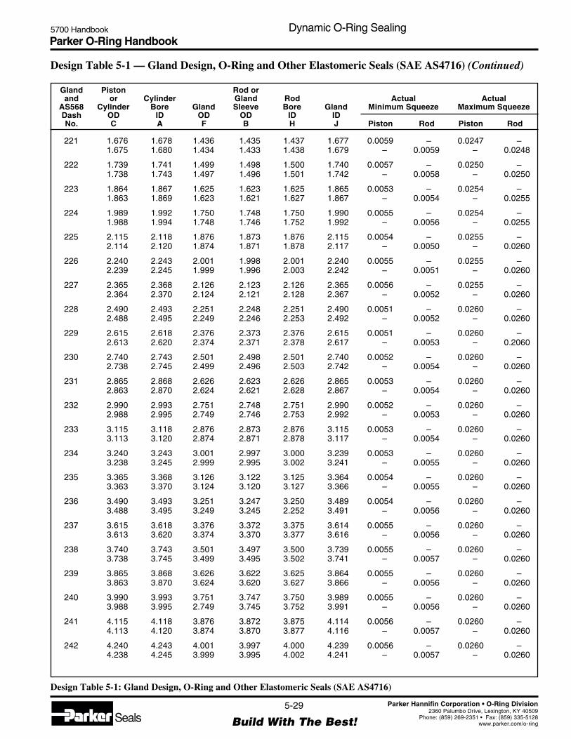
Parker O-Ring Handbook5700 Handbook Dynamic O-Ring Sealing
5-29
Build With The Best!SealsParker Hannifin Corporation • O-Ring Division
2360 Palumbo Drive, Lexington, KY 40509Phone: (859) 269-2351 • Fax: (859) 335-5128
www.parker.com/o-ring
Gland Piston Rod orand or Cylinder Gland Rod Actual Actual
AS568 Cylinder Bore Gland Sleeve Bore Gland Minimum Squeeze Maximum SqueezeDash OD ID OD OD ID IDNo. C A F B H J Piston Rod Piston Rod
Design Table 5-1: Gland Design, O-Ring and Other Elastomeric Seals (SAE AS4716)
Design Table 5-1 — Gland Design, O-Ring and Other Elastomeric Seals (SAE AS4716) (Continued)
221 1.676 1.678 1.436 1.435 1.437 1.677 0.0059 – 0.0247 –1.675 1.680 1.434 1.433 1.438 1.679 – 0.0059 – 0.0248
222 1.739 1.741 1.499 1.498 1.500 1.740 0.0057 – 0.0250 –1.738 1.743 1.497 1.496 1.501 1.742 – 0.0058 – 0.0250
223 1.864 1.867 1.625 1.623 1.625 1.865 0.0053 – 0.0254 –1.863 1.869 1.623 1.621 1.627 1.867 – 0.0054 – 0.0255
224 1.989 1.992 1.750 1.748 1.750 1.990 0.0055 – 0.0254 –1.988 1.994 1.748 1.746 1.752 1.992 – 0.0056 – 0.0255
225 2.115 2.118 1.876 1.873 1.876 2.115 0.0054 – 0.0255 –2.114 2.120 1.874 1.871 1.878 2.117 – 0.0050 – 0.0260
226 2.240 2.243 2.001 1.998 2.001 2.240 0.0055 – 0.0255 –2.239 2.245 1.999 1.996 2.003 2.242 – 0.0051 – 0.0260
227 2.365 2.368 2.126 2.123 2.126 2.365 0.0056 – 0.0255 –2.364 2.370 2.124 2.121 2.128 2.367 – 0.0052 – 0.0260
228 2.490 2.493 2.251 2.248 2.251 2.490 0.0051 – 0.0260 –2.488 2.495 2.249 2.246 2.253 2.492 – 0.0052 – 0.0260
229 2.615 2.618 2.376 2.373 2.376 2.615 0.0051 – 0.0260 –2.613 2.620 2.374 2.371 2.378 2.617 – 0.0053 – 0.2060
230 2.740 2.743 2.501 2.498 2.501 2.740 0.0052 – 0.0260 –2.738 2.745 2.499 2.496 2.503 2.742 – 0.0054 – 0.0260
231 2.865 2.868 2.626 2.623 2.626 2.865 0.0053 – 0.0260 –2.863 2.870 2.624 2.621 2.628 2.867 – 0.0054 – 0.0260
232 2.990 2.993 2.751 2.748 2.751 2.990 0.0052 – 0.0260 –2.988 2.995 2.749 2.746 2.753 2.992 – 0.0053 – 0.0260
233 3.115 3.118 2.876 2.873 2.876 3.115 0.0053 – 0.0260 –3.113 3.120 2.874 2.871 2.878 3.117 – 0.0054 – 0.0260
234 3.240 3.243 3.001 2.997 3.000 3.239 0.0053 – 0.0260 –3.238 3.245 2.999 2.995 3.002 3.241 – 0.0055 – 0.0260
235 3.365 3.368 3.126 3.122 3.125 3.364 0.0054 – 0.0260 –3.363 3.370 3.124 3.120 3.127 3.366 – 0.0055 – 0.0260
236 3.490 3.493 3.251 3.247 3.250 3.489 0.0054 – 0.0260 –3.488 3.495 3.249 3.245 2.252 3.491 – 0.0056 – 0.0260
237 3.615 3.618 3.376 3.372 3.375 3.614 0.0055 – 0.0260 –3.613 3.620 3.374 3.370 3.377 3.616 – 0.0056 – 0.0260
238 3.740 3.743 3.501 3.497 3.500 3.739 0.0055 – 0.0260 –3.738 3.745 3.499 3.495 3.502 3.741 – 0.0057 – 0.0260
239 3.865 3.868 3.626 3.622 3.625 3.864 0.0055 – 0.0260 –3.863 3.870 3.624 3.620 3.627 3.866 – 0.0056 – 0.0260
240 3.990 3.993 3.751 3.747 3.750 3.989 0.0055 – 0.0260 –3.988 3.995 2.749 3.745 3.752 3.991 – 0.0056 – 0.0260
241 4.115 4.118 3.876 3.872 3.875 4.114 0.0056 – 0.0260 –4.113 4.120 3.874 3.870 3.877 4.116 – 0.0057 – 0.0260
242 4.240 4.243 4.001 3.997 4.000 4.239 0.0056 – 0.0260 –4.238 4.245 3.999 3.995 4.002 4.241 – 0.0057 – 0.0260

Parker O-Ring Handbook5700 Handbook Dynamic O-Ring Sealing
5-30
Build With The Best!SealsParker Hannifin Corporation • O-Ring Division
2360 Palumbo Drive, Lexington, KY 40509Phone: (859) 269-2351 • Fax: (859) 335-5128
www.parker.com/o-ring
Gland Piston Rod orand or Cylinder Gland Rod Actual Actual
AS568 Cylinder Bore Gland Sleeve Bore Gland Minimum Squeeze Maximum SqueezeDash OD ID OD OD ID IDNo. C A F B H J Piston Rod Piston Rod
Design Table 5-1: Gland Design, O-Ring and Other Elastomeric Seals (SAE AS4716)
243 4.365 4.368 4.126 4.122 4.125 4.364 0.0056 – 0.0260 –4.363 4.370 4.124 1.120 4.127 4.366 – 0.0057 – 0.0260
244 4.489 4.493 4.251 4.247 4.250 4.489 0.0051 – 0.0265 –4.487 4.495 4.249 4.245 4.252 4.491 – 0.0057 – 0.0260
245 4.614 4.618 4.376 4.372 4.375 4.614 0.0051 – 0.0265 –4.612 4.620 4.374 4.370 4.377 4.616 – 0.0058 – 0.0260
246 4.739 4.743 4.501 4.497 4.501 4.739 0.0052 – 0.0265 –4.737 4.745 4.499 4.495 4.503 4.741 – 0.0053 – 0.0265
247 4.864 4.868 4.626 4.622 4.626 4.864 0.0052 – 0.0265 –4.862 4.870 4.624 4.620 4.628 4.866 – 0.0053 – 0.0265
325 1.864 1.867 1.495 1.498 1.500 1.870 0.0081 – 0.0322 –1.863 1.869 1.493 1.496 1.502 1.872 – 0.0079 – 0.0318
326 1.989 1.992 1.620 1.623 1.625 1.995 0.0083 – 0.0323 –1.988 1.994 1.618 1.621 1.627 1.997 – 0.0081 – 0.0319
327 2.115 2.118 1.746 1.748 1.750 2.120 0.0085 – 0.0322 –2.114 2.120 1.744 1.746 1.752 2.122 – 0.0083 – 0.0320
328 2.240 2.243 1.871 1.873 1.876 2.245 0.0087 – 0.0323 –2.239 2.245 1.869 1.871 1.878 2.247 – 0.0080 – 0.0325
329 2.365 2.368 1.996 1.998 2.001 2.370 0.0086 – 0.0326 –2.364 2.370 1.994 1.996 2.003 2.372 – 0.0080 – 0.0329
330 2.490 2.493 2.121 2.123 2.126 2.495 0.0083 – 0.0332 –2.488 2.495 2.119 2.121 2.128 2.497 – 0.0081 – 0.0330
331 2.615 2.618 2.246 2.248 2.251 2.620 0.0084 – 0.0332 –2.613 2.620 2.244 2.246 2.253 2.622 – 0.0083 – 0.0330
332 2.740 2.743 2.371 2.373 2.376 2.745 0.0085 – 0.0332 –2.738 2.745 2.369 2.371 2.378 2.747 – 0.0084 – 0.0330
333 2.865 2.868 2.496 2.498 2.501 2.870 0.0085 – 0.0334 –2.863 2.870 2.494 2.496 2.503 2.872 – 0.0084 – 0.0332
334 2.990 2.993 2.621 2.623 2.626 2.995 0.0087 – 0.0334 –2.988 2.995 2.619 2.621 2.628 2.997 – 0.0085 – 0.0332
335 3.115 3.118 2.746 2.748 2.751 3.120 0.0088 – 0.0334 –3.113 3.120 2.744 2.746 2.753 3.122 – 0.0087 – 0.0332
336 3.240 3.243 2.871 2.873 2.876 3.245 0.0089 – 0.0334 –3.238 3.245 2.869 2.871 2.878 3.247 – 0.0088 – 0.0332
337 3.365 3.368 2.996 2.997 3.000 3.369 0.0087 – 0.0335 –3.363 3.370 2.994 2.995 3.002 3.371 – 0.0087 – 0.0335
338 3.490 3.493 3.121 3.122 3.125 3.494 0.0088 – 0.0335 –3.488 3.495 3.119 3.120 3.127 3.496 – 0.0088 – 0.0335
339 3.615 3.618 3.246 3.247 3.250 3.619 0.0089 – 0.0335 –3.613 3.620 3.244 3.245 3.252 3.621 – 0.0089 – 0.0335
340 3.740 3.743 3.371 3.372 3.375 3.744 0.0090 – 0.0335 –3.738 3.745 3.369 3.370 3.377 3.746 – 0.0090 – 0.0335
341 3.865 3.868 3.496 3.497 3.500 3.869 0.0091 – 0.0335 –3.863 3.870 3.494 3.495 3.502 3.871 – 0.0090 – 0.0335
Design Table 5-1 — Gland Design, O-Ring and Other Elastomeric Seals (SAE AS4716) (Continued)
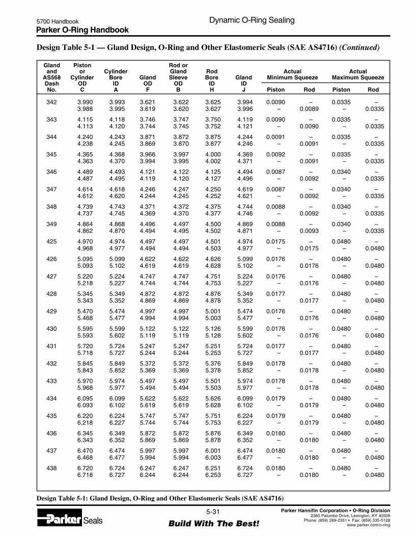
Parker O-Ring Handbook5700 Handbook Dynamic O-Ring Sealing
5-31
Build With The Best!SealsParker Hannifin Corporation • O-Ring Division
2360 Palumbo Drive, Lexington, KY 40509Phone: (859) 269-2351 • Fax: (859) 335-5128
www.parker.com/o-ring
Gland Piston Rod orand or Cylinder Gland Rod Actual Actual
AS568 Cylinder Bore Gland Sleeve Bore Gland Minimum Squeeze Maximum SqueezeDash OD ID OD OD ID IDNo. C A F B H J Piston Rod Piston Rod
Design Table 5-1: Gland Design, O-Ring and Other Elastomeric Seals (SAE AS4716)
Design Table 5-1 — Gland Design, O-Ring and Other Elastomeric Seals (SAE AS4716) (Continued)
342 3.990 3.993 3.621 3.622 3.625 3.994 0.0090 – 0.0335 –3.988 3.995 3.619 3.620 3.627 3.996 – 0.0089 – 0.0335
343 4.115 4.118 3.746 3.747 3.750 4.119 0.0090 – 0.0335 –4.113 4.120 3.744 3.745 3.752 4.121 – 0.0090 – 0.0335
344 4.240 4.243 3.871 3.872 3.875 4.244 0.0091 – 0.0335 –4.238 4.245 3.869 3.870 3.877 4.246 – 0.0091 – 0.0335
345 4.365 4.368 3.966 3.997 4.000 4.369 0.0092 – 0.0335 –4.363 4.370 3.994 3.995 4.002 4.371 – 0.0091 – 0.0335
346 4.489 4.493 4.121 4.122 4.125 4.494 0.0087 – 0.0340 –4.487 4.495 4.119 4.120 4.127 4.496 – 0.0092 – 0.0335
347 4.614 4.618 4.246 4.247 4.250 4.619 0.0087 – 0.0340 –4.612 4.620 4.244 4.245 4.252 4.621 – 0.0092 – 0.0335
348 4.739 4.743 4.371 4.372 4.375 4.744 0.0088 – 0.0340 –4.737 4.745 4.369 4.370 4.377 4.746 – 0.0092 – 0.0335
349 4.864 4.868 4.496 4.497 4.500 4.869 0.0088 – 0.0340 –4.862 4.870 4.494 4.495 4.502 4.871 – 0.0093 – 0.0335
425 4.970 4.974 4.497 4.497 4.501 4.974 0.0175 – 0.0480 –4.968 4.977 4.494 4.494 4.503 4.977 – 0.0175 – 0.0480
426 5.095 5.099 4.622 4.622 4.626 5.099 0.0176 – 0.0480 –5.093 5.102 4.619 4.619 4.628 5.102 – 0.0176 – 0.0480
427 5.220 5.224 4.747 4.747 4.751 5.224 0.0176 – 0.0480 –5.218 5.227 4.744 4.744 4.753 5.227 – 0.0176 – 0.0480
428 5.345 5.349 4.872 4.872 4.876 5.349 0.0177 – 0.0480 –5.343 5.352 4.869 4.869 4.878 5.352 – 0.0177 – 0.0480
429 5.470 5.474 4.997 4.997 5.001 5.474 0.0176 – 0.0480 –5.468 5.477 4.994 4.994 5.003 5.477 – 0.0176 – 0.0480
430 5.595 5.599 5.122 5.122 5.126 5.599 0.0176 – 0.0480 –5.593 5.602 5.119 5.119 5.128 5.602 – 0.0176 – 0.0480
431 5.720 5.724 5.247 5.247 5.251 5.724 0.0177 – 0.0480 –5.718 5.727 5.244 5.244 5.253 5.727 – 0.0177 – 0.0480
432 5.845 5.849 5.372 5.372 5.376 5.849 0.0178 – 0.0480 –5.843 5.852 5.369 5.369 5.378 5.852 – 0.0178 – 0.0480
433 5.970 5.974 5.497 5.497 5.501 5.974 0.0178 – 0.0480 –5.968 5.977 5.494 5.494 5.503 5.977 – 0.0178 – 0.0480
434 6.095 6.099 5.622 5.622 5.626 6.099 0.0179 – 0.0480 –6.093 6.102 5.619 5.619 5.628 6.102 – 0.0179 – 0.0480
435 6.220 6.224 5.747 5.747 5.751 6.224 0.0179 – 0.0480 –6.218 6.227 5.744 5.744 5.753 6.227 – 0.0179 – 0.0480
436 6.345 6.349 5.872 5.872 5.876 6.349 0.0180 – 0.0480 –6.343 6.352 5.869 5.869 5.878 6.352 – 0.0180 – 0.0480
437 6.470 6.474 5.997 5.997 6.001 6.474 0.0180 – 0.0480 –6.468 6.477 5.994 5.994 6.003 6.477 – 0.0180 – 0.0480
438 6.720 6.724 6.247 6.247 6.251 6.724 0.0180 – 0.0480 –6.718 6.727 6.244 6.244 6.253 6.727 – 0.0180 – 0.0480

Parker O-Ring Handbook5700 Handbook Dynamic O-Ring Sealing
5-32
Build With The Best!SealsParker Hannifin Corporation • O-Ring Division
2360 Palumbo Drive, Lexington, KY 40509Phone: (859) 269-2351 • Fax: (859) 335-5128
www.parker.com/o-ring
Gland Piston Rod orand or Cylinder Gland Rod Actual Actual
AS568 Cylinder Bore Gland Sleeve Bore Gland Minimum Squeeze Maximum SqueezeDash OD ID OD OD ID IDNo. C A F B H J Piston Rod Piston Rod
Design Table 5-1: Gland Design, O-Ring and Other Elastomeric Seals (SAE AS4716)
439 6.970 6.974 6.497 6.497 6.501 6.974 0.0181 – 0.0480 –6.968 6.977 6.494 6.494 6.504 6.977 – 0.0176 – 0.0485
440 7.220 7.224 6.747 6.747 6.751 7.224 0.0182 – 0.0480 –7.218 7.227 6.744 6.744 6.754 7.227 – 0.0177 – 0.0485
441 7.470 7.474 6.997 6.997 7.001 7.474 0.0182 – 0.0480 –7.468 7.477 6.994 6.994 7.004 7.477 – 0.0177 – 0.0485
442 7.720 7.724 7.247 7.247 7.251 7.724 0.0181 – 0.0480 –7.718 7.727 7.244 7.244 7.254 7.727 – 0.0176 – 0.0485
443 7.970 7.974 7.497 7.497 7.501 7.974 0.0182 – 0.0480 –7.968 7.977 7.494 7.494 7.504 7.977 – 0.0177 – 0.0485
444 8.220 8.224 7.747 7.747 7.751 8.224 0.0183 – 0.0480 –8.218 8.227 7.744 7.744 7.754 8.227 – 0.0178 – 0.0485
445 8.470 8.474 7.997 7.997 8.001 8.474 0.0183 – 0.0480 –8.468 8.477 7.994 7.994 8.004 8.477 – 0.0178 – 0.0485
446 8.970 8.974 8.497 8.497 8.501 8.974 0.0177 – 0.0485 –8.967 8.977 8.494 8.494 8.504 8.977 – 0.0177 – 0.0485
447 9.470 9.474 8.997 8.997 9.001 9.474 0.0168 – 0.0485 –9.467 9.478 8.994 8.994 9.004 9.478 – 0.0173 – 0.0485
448 9.970 9.974 9.497 9.497 9.501 9.974 0.0169 – 0.0485 –9.967 9.978 9.494 9.494 9.504 9.978 – 0.0174 – 0.0485
449 10.470 10.474 9.997 9.997 10.001 10.474 0.0170 – 0.0485 –10.467 10.478 9.994 9.994 10.004 10.478 – 0.0175 – 0.0485
450 10.970 10.974 10.497 10.497 10.501 10.974 0.0170 – 0.0485 –10.967 10.978 10.494 10.494 10.504 10.978 – 0.0175 – 0.0485
451 11.470 11.474 10.997 10.997 11.001 11.474 0.0170 – 0.0485 –11.467 11.478 10.994 10.994 11.004 11.478 – 0.0176 – 0.0485
452 11.970 11.974 11.497 11.497 11.501 11.974 0.0171 – 0.0485 –11.967 11.978 11.494 11.494 11.504 11.978 – 0.0176 – 0.0485
453 12.470 12.474 11.997 11.997 12.001 12.474 0.0172 – 0.0485 –12.467 12.478 11.994 11.994 12.004 12.478 – 0.0177 – 0.0485
454 12.970 12.974 12.497 12.497 12.501 12.974 0.0173 – 0.0485 –12.967 12.978 12.494 12.494 12.504 12.978 – 0.0178 – 0.0485
455 13.470 13.474 12.997 12.997 13.001 13.474 0.0173 – 0.0485 –13.467 13.478 12.994 12.994 13.004 13.478 – 0.0178 – 0.0485
456 13.970 13.974 13.497 13.497 13.501 13.974 0.0172 – 0.0485 –13.967 13.978 13.494 13.494 13.504 13.978 – 0.0177 – 0.0485
457 14.470 14.474 13.997 13.997 14.001 14.474 0.0173 – 0.0485 –14.467 14.478 13.994 13.994 14.004 14.478 – 0.0178 – 0.0485
458 14.970 14.974 14.497 14.497 14.501 14.974 0.0173 – 0.0485 –14.967 14.978 14.494 14.494 14.504 14.978 – 0.0178 – 0.0485
459 15.470 15.474 14.997 14.997 15.001 15.474 0.0174 – 0.0485 –15.467 15.478 14.994 14.994 15.004 15.478 – 0.0179 – 0.0485
460 15.970 15.974 15.497 15.497 15.501 15.974 0.0174 – 0.0485 –15.967 15.978 15.494 15.494 15.504 15.978 – 0.0179 – 0.0485
Design Table 5-1 — Gland Design, O-Ring and Other Elastomeric Seals (SAE AS4716) (Continued)
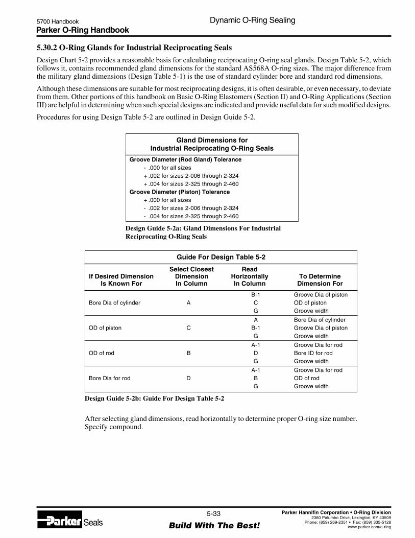
Parker O-Ring Handbook5700 Handbook Dynamic O-Ring Sealing
5-33
Build With The Best!SealsParker Hannifin Corporation • O-Ring Division
2360 Palumbo Drive, Lexington, KY 40509Phone: (859) 269-2351 • Fax: (859) 335-5128
www.parker.com/o-ring
Gland Dimensions forIndustrial Reciprocating O-Ring Seals
Groove Diameter (Rod Gland) Tolerance- .000 for all sizes+ .002 for sizes 2-006 through 2-324+ .004 for sizes 2-325 through 2-460
Groove Diameter (Piston) Tolerance+ .000 for all sizes- .002 for sizes 2-006 through 2-324- .004 for sizes 2-325 through 2-460
Design Guide 5-2a: Gland Dimensions For IndustrialReciprocating O-Ring Seals
5.30.2 O-Ring Glands for Industrial Reciprocating Seals
Design Chart 5-2 provides a reasonable basis for calculating reciprocating O-ring seal glands. Design Table 5-2, whichfollows it, contains recommended gland dimensions for the standard AS568A O-ring sizes. The major difference fromthe military gland dimensions (Design Table 5-1) is the use of standard cylinder bore and standard rod dimensions.
Although these dimensions are suitable for most reciprocating designs, it is often desirable, or even necessary, to deviatefrom them. Other portions of this handbook on Basic O-Ring Elastomers (Section II) and O-Ring Applications (SectionIII) are helpful in determining when such special designs are indicated and provide useful data for such modified designs.
Procedures for using Design Table 5-2 are outlined in Design Guide 5-2.
Guide For Design Table 5-2
Select Closest ReadIf Desired Dimension Dimension Horizontally To Determine
Is Known For In Column In Column Dimension For
B-1 Groove Dia of pistonBore Dia of cylinder A C OD of piston
G Groove width
A Bore Dia of cylinderOD of piston C B-1 Groove Dia of piston
G Groove width
A-1 Groove Dia for rodOD of rod B D Bore ID for rod
G Groove width
A-1 Groove Dia for rodBore Dia for rod D B OD of rod
G Groove width
Design Guide 5-2b: Guide For Design Table 5-2
After selecting gland dimensions, read horizontally to determine proper O-ring size number.Specify compound.
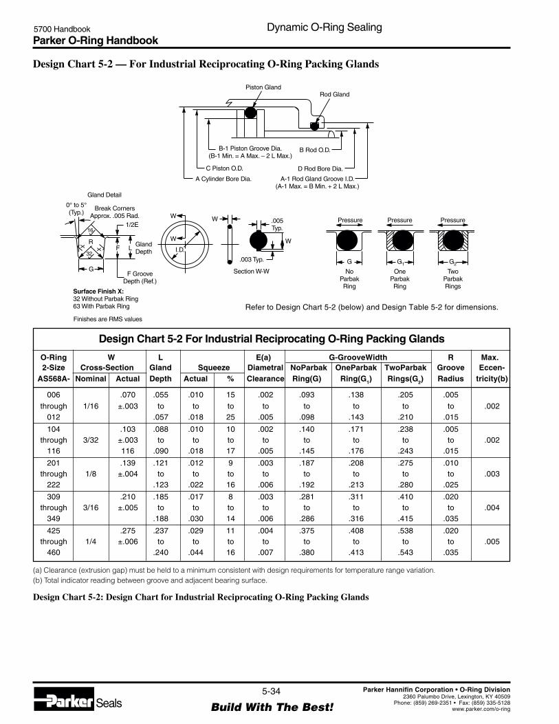
Parker O-Ring Handbook5700 Handbook Dynamic O-Ring Sealing
5-34
Build With The Best!SealsParker Hannifin Corporation • O-Ring Division
2360 Palumbo Drive, Lexington, KY 40509Phone: (859) 269-2351 • Fax: (859) 335-5128
www.parker.com/o-ring
Design Chart 5-2 — For Industrial Reciprocating O-Ring Packing Glands
Piston GlandRod Gland
B Rod O.D.B-1 Piston Groove Dia.(B-1 Min. = A Max. – 2 L Max.)
D Rod Bore Dia.C Piston O.D.
A-1 Rod Gland Groove I.D.(A-1 Max. = B Min. + 2 L Max.)
A Cylinder Bore Dia.
Gland Detail
1/2E
F L
G
R
16
X
32
X
0° to 5°(Typ.)
Break CornersApprox. .005 Rad.
GlandDepth
F GrooveDepth (Ref.)
Surface Finish X:32 Without Parbak Ring63 With Parbak Ring
NoParbakRing
OneParbakRing
Pressure.005Typ.
W
WW
W
I.D.
.003 Typ.
Section W-W
Pressure Pressure
TwoParbakRings
G2G G1
Finishes are RMS values
Refer to Design Chart 5-2 (below) and Design Table 5-2 for dimensions.
O-Ring W L E(a) G-GrooveWidth R Max.2-Size Cross-Section Gland Squeeze Diametral NoParbak OneParbak TwoParbak Groove Eccen-
AS568A- Nominal Actual Depth Actual % Clearance Ring(G) Ring(G1) Rings(G2) Radius tricity(b)
006 .070 .055 .010 15 .002 .093 .138 .205 .005
through 1/16 ±.003 to to to to to to to to .002012 .057 .018 25 .005 .098 .143 .210 .015
104 .103 .088 .010 10 .002 .140 .171 .238 .005through 3/32 ±.003 to to to to to to to to .002
116 116 .090 .018 17 .005 .145 .176 .243 .015
201 .139 .121 .012 9 .003 .187 .208 .275 .010through 1/8 ±.004 to to to to to to to to .003
222 .123 .022 16 .006 .192 .213 .280 .025
309 .210 .185 .017 8 .003 .281 .311 .410 .020through 3/16 ±.005 to to to to to to to to .004
349 .188 .030 14 .006 .286 .316 .415 .035
425 .275 .237 .029 11 .004 .375 .408 .538 .020through 1/4 ±.006 to to to to to to to to .005
460 .240 .044 16 .007 .380 .413 .543 .035
Design Chart 5-2 For Industrial Reciprocating O-Ring Packing Glands
(a) Clearance (extrusion gap) must be held to a minimum consistent with design requirements for temperature range variation.(b) Total indicator reading between groove and adjacent bearing surface.
Design Chart 5-2: Design Chart for Industrial Reciprocating O-Ring Packing Glands

Parker O-Ring Handbook5700 Handbook Dynamic O-Ring Sealing
5-35
Build With The Best!SealsParker Hannifin Corporation • O-Ring Division
2360 Palumbo Drive, Lexington, KY 40509Phone: (859) 269-2351 • Fax: (859) 335-5128
www.parker.com/o-ring
Design Table 5-2 — Gland Dimensions for Industrial Reciprocating O-Ring Seals,103.5 Bar (1500 PSI) Max.†
006 .114 .005 .254 .249 .234 .124 .139 *.247 .126007 .145 .005 .285 .280 .265 .155 .170 *.278 .157008 .176 .005 .316 .311 .296 .186 .201 *.309 .188009 .208 .005 .070 .348 .343 .328 .218 .233 *.341 .220 .093010 .239 .005 ±.003 .379 .374 .359 .249 .264 *.372 .251
011 .301 .005 .441 .436 .421 .311 .326 *.434 .313012 .364 .005 .504 .499 .484 .374 .389 *.497 .376
104 .112 .005 .318 .312 .300 .124 .136 *.310 .126105 .143 .005 .349 .343 .331 .155 .167 *.341 .157106 .174 .005 .380 .374 .362 .186 .198 *.372 .188107 .206 .005 .412 .406 .394 .218 .230 *.404 .220108 .237 .005 .443 .437 .425 .249 .261 *.435 .251
109 .299 .005 .505 .499 .487 .311 .323 *.497 .313110 .362 .005 .103 .568 .562 .550 .374 .386 *.560 .376 .140111 .424 .005 ±.003 .630 .624 .612 .436 .488 *.622 .438112 .487 .005 .693 .687 .675 .499 .511 *.685 .501113 .549 .007 .755 .749 .737 .561 .573 *.747 .563
114 .612 .009 .818 .812 .800 .624 .636 .810 .626115 .674 .009 .880 .874 .862 .686 .698 .872 .688116 .737 .009 .943 .937 .925 .749 .761 .935 .751
201 .171 .005 .449 .437 .427 .185 .195 *.434 .188202 .234 .005 .512 .500 .490 .248 .258 *.497 .251203 .296 .005 .574 .562 .552 .310 .320 *.559 .313204 .359 .005 .637 .625 .615 .373 .383 .662 .376205 .421 .005 .699 .687 .677 .435 .445 .684 .438
206 .484 .005 .762 .750 .740 .498 .508 .747 .501207 .546 .007 .824 .812 .802 .560 .570 .809 .563208 .609 .009 .887 .875 .865 .623 .633 .872 .626209 .671 .009 .949 .937 .927 .685 .695 .934 .688210 .734 .010 1.012 1.000 .990 .748 .758 .997 .751
211 .796 .010 .139 1.074 1.062 1.052 .810 .820 1.059 .813 .187212 .859 .010 ±.004 1.137 1.125 1.115 .873 .883 1.122 .876213 .921 .010 1.199 1.187 1.177 .935 .945 1.184 .938214 .984 .010 1.262 1.250 1.240 .998 1.008 1.247 1.001215 1.046 .010 1.324 1.312 1.302 1.060 1.070 1.309 1.063
216 1.109 .012 1.387 1.375 1.365 1.123 1.133 1.372 1.126217 1.171 .012 1.449 1.437 1.427 1.185 1.195 1.434 1.188218 1.234 .012 1.512 1.500 1.490 1.248 1.258 1.497 1.251219 1.296 .012 1.574 1.562 1.552 1.310 1.320 1.559 1.313220 1.359 .012 1.637 1.625 1.615 1.373 1.383 1.622 1.376
221 1.421 .012 1.699 1.687 1.677 1.435 1.445 1.684 1.438222 1.484 .015 1.762 1.750 1.740 1.498 1.508 1.747 1.501
* These designs require considerable installation stretch. If assembly breakage is incurred use a compound having higher elongationor use a two-piece piston.
† This groove width does not permit the use of Parbak rings. For pressures above 103.5 Bar (1500 PSI), consult Design Chart 5-2 forgroove widths where Parbak rings must be used.
O-RingSize
Parker No.2-
DimensionsMean
I.D. ± W O.D. (Ref)
ABore Dia.(Cylinder)
+.002-.000
A-1Groove Dia.(Rod Gland)
+.002-.000
BOD
(Rod)+.000-.002
B-1Groove Dia.
*(Piston)+.000-.002
COD
(Piston)+.000-.001
DBore Dia.
(Rod)+.001-.000
G†Width
Groove+.005-.000
Design Table 5-2: Gland Dimensions for Industrial Reciprocating O-Ring Seals, 103.5 Bar (1500 PSI) Max.†
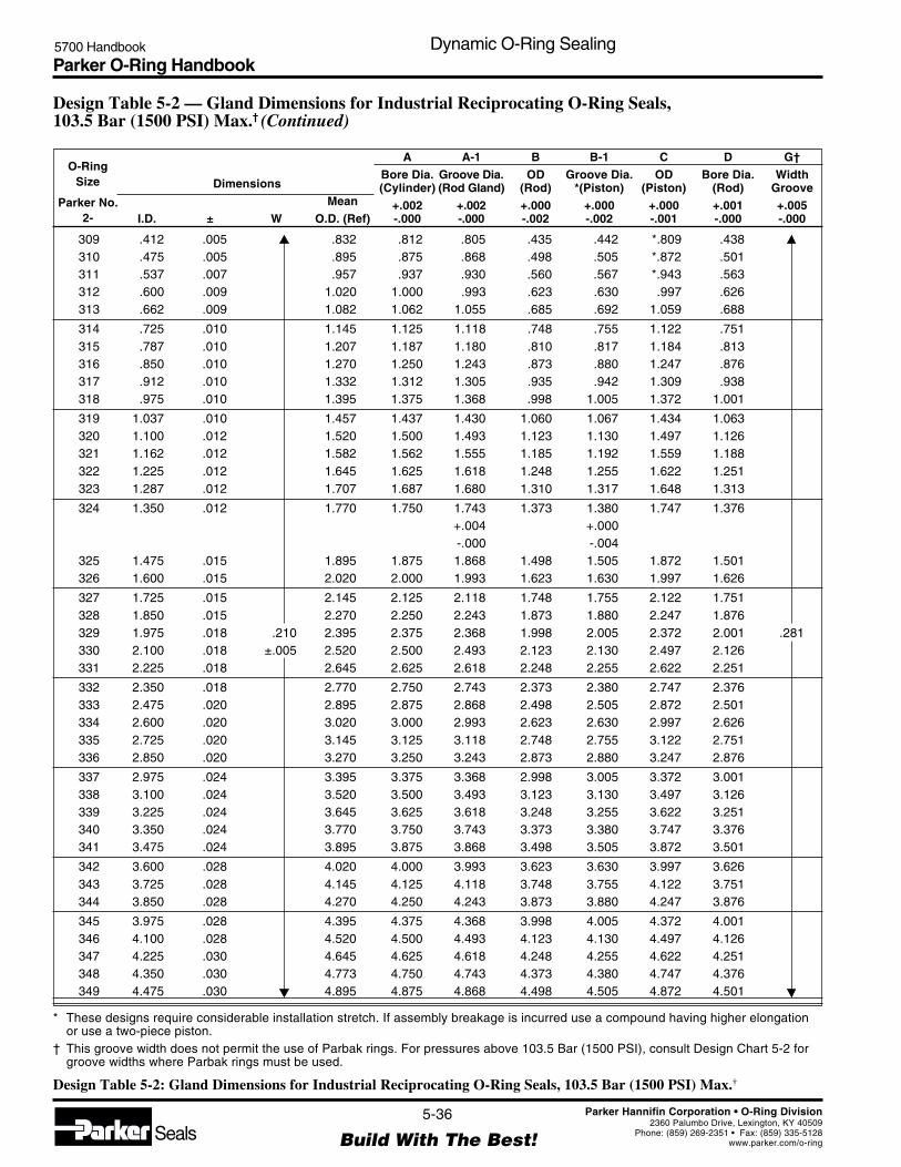
Parker O-Ring Handbook5700 Handbook Dynamic O-Ring Sealing
5-36
Build With The Best!SealsParker Hannifin Corporation • O-Ring Division
2360 Palumbo Drive, Lexington, KY 40509Phone: (859) 269-2351 • Fax: (859) 335-5128
www.parker.com/o-ring
309 .412 .005 .832 .812 .805 .435 .442 *.809 .438310 .475 .005 .895 .875 .868 .498 .505 *.872 .501311 .537 .007 .957 .937 .930 .560 .567 *.943 .563312 .600 .009 1.020 1.000 .993 .623 .630 .997 .626313 .662 .009 1.082 1.062 1.055 .685 .692 1.059 .688
314 .725 .010 1.145 1.125 1.118 .748 .755 1.122 .751315 .787 .010 1.207 1.187 1.180 .810 .817 1.184 .813316 .850 .010 1.270 1.250 1.243 .873 .880 1.247 .876317 .912 .010 1.332 1.312 1.305 .935 .942 1.309 .938318 .975 .010 1.395 1.375 1.368 .998 1.005 1.372 1.001
319 1.037 .010 1.457 1.437 1.430 1.060 1.067 1.434 1.063320 1.100 .012 1.520 1.500 1.493 1.123 1.130 1.497 1.126321 1.162 .012 1.582 1.562 1.555 1.185 1.192 1.559 1.188322 1.225 .012 1.645 1.625 1.618 1.248 1.255 1.622 1.251323 1.287 .012 1.707 1.687 1.680 1.310 1.317 1.648 1.313
324 1.350 .012 1.770 1.750 1.743 1.373 1.380 1.747 1.376+.004 +.000-.000 -.004
325 1.475 .015 1.895 1.875 1.868 1.498 1.505 1.872 1.501326 1.600 .015 2.020 2.000 1.993 1.623 1.630 1.997 1.626
327 1.725 .015 2.145 2.125 2.118 1.748 1.755 2.122 1.751328 1.850 .015 2.270 2.250 2.243 1.873 1.880 2.247 1.876329 1.975 .018 .210 2.395 2.375 2.368 1.998 2.005 2.372 2.001 .281330 2.100 .018 ±.005 2.520 2.500 2.493 2.123 2.130 2.497 2.126331 2.225 .018 2.645 2.625 2.618 2.248 2.255 2.622 2.251
332 2.350 .018 2.770 2.750 2.743 2.373 2.380 2.747 2.376333 2.475 .020 2.895 2.875 2.868 2.498 2.505 2.872 2.501334 2.600 .020 3.020 3.000 2.993 2.623 2.630 2.997 2.626335 2.725 .020 3.145 3.125 3.118 2.748 2.755 3.122 2.751336 2.850 .020 3.270 3.250 3.243 2.873 2.880 3.247 2.876
337 2.975 .024 3.395 3.375 3.368 2.998 3.005 3.372 3.001338 3.100 .024 3.520 3.500 3.493 3.123 3.130 3.497 3.126339 3.225 .024 3.645 3.625 3.618 3.248 3.255 3.622 3.251340 3.350 .024 3.770 3.750 3.743 3.373 3.380 3.747 3.376341 3.475 .024 3.895 3.875 3.868 3.498 3.505 3.872 3.501
342 3.600 .028 4.020 4.000 3.993 3.623 3.630 3.997 3.626343 3.725 .028 4.145 4.125 4.118 3.748 3.755 4.122 3.751344 3.850 .028 4.270 4.250 4.243 3.873 3.880 4.247 3.876
345 3.975 .028 4.395 4.375 4.368 3.998 4.005 4.372 4.001346 4.100 .028 4.520 4.500 4.493 4.123 4.130 4.497 4.126347 4.225 .030 4.645 4.625 4.618 4.248 4.255 4.622 4.251348 4.350 .030 4.773 4.750 4.743 4.373 4.380 4.747 4.376349 4.475 .030 4.895 4.875 4.868 4.498 4.505 4.872 4.501
O-RingSize
Parker No.2-
DimensionsMean
I.D. ± W O.D. (Ref)
ABore Dia.(Cylinder)
+.002-.000
A-1Groove Dia.(Rod Gland)
+.002-.000
BOD
(Rod)+.000-.002
B-1Groove Dia.
*(Piston)+.000-.002
COD
(Piston)+.000-.001
DBore Dia.
(Rod)+.001-.000
G†Width
Groove+.005-.000
* These designs require considerable installation stretch. If assembly breakage is incurred use a compound having higher elongationor use a two-piece piston.
† This groove width does not permit the use of Parbak rings. For pressures above 103.5 Bar (1500 PSI), consult Design Chart 5-2 forgroove widths where Parbak rings must be used.
Design Table 5-2 — Gland Dimensions for Industrial Reciprocating O-Ring Seals,103.5 Bar (1500 PSI) Max.† (Continued)
Design Table 5-2: Gland Dimensions for Industrial Reciprocating O-Ring Seals, 103.5 Bar (1500 PSI) Max.†

Parker O-Ring Handbook5700 Handbook Dynamic O-Ring Sealing
5-37
Build With The Best!SealsParker Hannifin Corporation • O-Ring Division
2360 Palumbo Drive, Lexington, KY 40509Phone: (859) 269-2351 • Fax: (859) 335-5128
www.parker.com/o-ring
425 4.475 .033 5.025 5.002 4.971 4.497 4.528 4.998 4.501426 4.600 .033 5.150 5.127 5.096 4.622 4.653 5.123 4.626427 4.725 .033 5.275 5.252 5.221 4.747 4.778 5.248 4.751428 4.850 .033 5.400 5.377 5.346 4.872 4.903 5.373 4.876429 4.975 .037 5.525 5.502 5.471 4.997 5.028 5.498 5.001
430 5.100 .037 5.650 5.627 5.596 5.122 5.153 5.623 5.126431 5.225 .037 5.775 5.752 5.721 5.247 5.278 5.748 5.251432 5.350 .037 5.900 5.877 5.846 5.372 5.403 5.873 5.376433 5.475 .037 6.025 6.002 5.971 5.497 5.528 5.998 5.501434 5.600 .037 6.150 6.127 6.096 5.622 5.653 6.123 5.626
435 5.725 .037 6.275 6.252 6.221 5.747 5.778 6.248 5.751436 5.850 .037 6.400 6.377 6.346 5.872 5.903 6.373 5.876437 5.975 .037 6.525 6.502 6.471 5.997 6.028 6.498 6.001438 6.225 .040 6.775 6.752 6.721 6.247 6.278 6.748 6.251439 6.475 .040 7.025 7.002 6.971 6.497 6.528 6.998 6.501
440 6.725 .040 7.275 7.252 7.221 6.747 6.778 7.248 6.751441 6.975 .040 7.525 7.502 7.471 6.997 7.028 7.498 7.001442 7.225 .045 .275 7.775 7.752 4.721 7.247 7.278 7.748 7.251 .375443 7.475 .045 ±.006 8.025 8.002 7.971 7.497 7.528 7.998 7.501444 7.725 .045 8.275 8.252 8.221 7.747 7.778 8.248 7.751
445 7.975 .045 8.525 8.502 8.471 7.997 8.028 8.498 8.001446 8.475 .055 9.025 9.002 8.971 8.497 8.528 8.998 8.501447 8.975 .055 9.525 9.502 9.471 8.997 9.028 9.498 9.001448 9.475 .055 10.025 10.002 9.971 9.497 9.528 9.998 9.501449 9.975 .055 10.525 10.502 10.471 9.997 10.028 10.498 10.001
450 10.475 .060 11.025 11.002 10.971 10.497 10.528 10.998 10.501451 10.975 .060 11.525 11.502 11.471 10.997 11.028 11.498 11.001452 11.475 .060 12.025 12.002 11.971 11.497 11.528 11.998 11.501453 11.975 .060 12.525 12.502 12.471 11.997 12.028 12.498 12.001454 12.475 .060 13.025 13.002 12.971 12.497 12.528 12.998 12.501
455 12.975 .060 13.525 13.502 13.471 12.997 13.028 13.498 13.001456 13.475 .070 14.025 14.002 13.971 13.497 13.528 13.998 13.501457 13.975 .070 14.525 14.502 14.471 13.997 14.028 14.498 14.001458 14.475 .070 15.025 15.002 14.971 14.497 14.528 14.998 14.501459 14.975 .070 15.525 15.502 15.471 14.997 15.028 15.498 15.001
460 15.475 .070 16.025 16.002 15.971 15.497 15.528 15.998 15.501
O-RingSize
Parker No.2-
DimensionsMean
I.D. ± W O.D. (Ref)
ABore Dia.(Cylinder)
+.002-.000
A-1Groove Dia.(Rod Gland)
+.004-.000
BOD
(Rod)+.000-.002
B-1Groove Dia.
*(Piston)+.000-.004
COD
(Piston)+.000-.001
DBore Dia.
(Rod)+.001-.000
G†Width
Groove+.005-.000
* These designs require considerable installation stretch. If assembly breakage is incurred use a compound having higher elongationor use a two-piece piston.
† This groove width does not permit the use of Parbak rings. For pressures above 103.5 Bar (1500 PSI), consult Design Chart 5-2 forgroove widths where Parbak rings must be used.
Design Table 5-2 — Gland Dimensions for Industrial Reciprocating O-Ring Seals,103.5 Bar (1500 PSI) Max.† (Continued)
Design Table 5-2: Gland Dimensions for Industrial Reciprocating O-Ring Seals, 103.5 Bar (1500 PSI) Max.†

Parker O-Ring Handbook5700 Handbook Dynamic O-Ring Sealing
5-38
Build With The Best!SealsParker Hannifin Corporation • O-Ring Division
2360 Palumbo Drive, Lexington, KY 40509Phone: (859) 269-2351 • Fax: (859) 335-5128
www.parker.com/o-ring
5.30.3 O-Ring Glands for Pneumatic Floating Piston Ring Seals
Design Chart 5-3 provides the basis for calculating gland dimensions. For standard O-ring sizes, these dimensions havebeen calculated and are listed in Design Table 5-3. The procedures for the use of Design Table 5-3 are outlined in DesignGuide 5-3.
Guide For Design Table 5-3
Select Closest ReadIf Desired Dimension Dimension Horizontally To Determine
Is Known For In Column In Column Dimension For
Bore Dia of cylinder B-1 Groove Dia of pistonA C OD of piston
G Groove widthA Bore Dia of cylinder
OD of piston C B-1 Groove Dia of pistonG Groove width
Design Guide 5-3: Guide For Design Table 5-3
After selecting gland dimensions, read horizontally to determine proper O-ring size number.Specify compound.
Refer to 8-2, Military Fluid Specification Description, Fluid Compatibility Tables, or Table3-1 to select the proper compound. The effective part number for an O-ring consists of botha size number and a compound number.

Parker O-Ring Handbook5700 Handbook Dynamic O-Ring Sealing
5-39
Build With The Best!SealsParker Hannifin Corporation • O-Ring Division
2360 Palumbo Drive, Lexington, KY 40509Phone: (859) 269-2351 • Fax: (859) 335-5128
www.parker.com/o-ring
Design Chart 5-3 — Floating Pneumatic Piston Ring Seal Glands 13.8 Bar (200 PSI) Max.
B-1 Piston Groove O.D.(B-1 Max. = A Min. – 2 L Min.)
A Cylinder Bore Dia.[A Min. = (O-Ring Mean O.D.) — P]
Gland Detail
1/2 E
F L
G
R
16
32
32 32
0° to 5° Typ.(0° Preferred)
Break EdgesApprox. .005 Rad.
GlandDepth
F GrooveDepth (Ref.)
Rod Seal GlandUse Data in Chart 5-2 andTable 5-2 for IndustrialReciprocating Seals.Floating O-ring DesignDoes Not Apply toRod Seals.
C Piston O.D.
1/2 E
.005Typ.
W
WW
W
I.D.
.003 Typ.
Section W-W
Finishes are RMS values
Design Chart 5-3 — Floating Pneumatic Piston Ring Seal GlandsO-Ring W P (c)Size (a) Cross Section Peripheral L G E RParker Squeeze Gland Groove Diametral Eccentricity GrooveNo. 2- Nominal Actual (Variable) Depth Width Clearance Max. (b) Radius
006 .035 .072 .075 .002 .005through 1/16 .070 to to to to .002 to
012 ±.003 .042 .076 .079 .010 .015104 .038 .105 .111 .002 .005
through 3/32 .103 to to to to .002 to116 ±.003 .062 .109 .115 .010 .015201 .061 .143 .151 .003 .010
through 1/8 .139 to to to to .003 to222 ±.004 .082 .147 .155 .011 .025309 .084 .214 .229 .003 .020
through 3/16 .210 to to to to .004 to349 ±.005 .124 .218 .233 .011 .035425 .140 .282 .301 .004 .020
through 1/4 .275 to to to to .005 to460 ±.006 .175 .286 .305 .012 .035
(a) Only sizes listed are recommended for this design.(b) Total indicator reading between groove and adjacent bearing surface.(c) Use to calculate Amin diameter.
Design Chart 5-3: Design Chart for Floating Pneumatic Piston Ring Seal Glands
Refer to Design Chart 5-3 (below) and Design Table 5-3 for dimensions.

Parker O-Ring Handbook5700 Handbook Dynamic O-Ring Sealing
5-40
Build With The Best!SealsParker Hannifin Corporation • O-Ring Division
2360 Palumbo Drive, Lexington, KY 40509Phone: (859) 269-2351 • Fax: (859) 335-5128
www.parker.com/o-ring
Design Table 5-3 — Floating Pneumatic Piston Ring Seal Gland Dimensions
O-RingSize
Parker No.2-
DimensionsMean
I.D. ± W O.D. (Ref)
ABore Dia.(Cylinder)
+.004-.000
B-1Groove Dia.
(Piston)+.000-.004
COD
(Piston)+.000-.004
GGrooveWidth+.004-.000
P
PeripheralSqueeze
006 .114 .005 .254 .219 .075 *.217 .035007 .145 .005 .285 .249 .105 *.247 .036008 .176 .005 .316 .279 .135 *.277 .037009 .208 .005 .070 .348 .309 .165 *.307 .075 .039010 .239 .005 ±.003 .379 .339 .195 *.377 .040
011 .301 .005 .441 .400 .256 *.398 .041012 .364 .005 .504 .462 .318 .460 .042
104 .112 .005 .318 .280 .070 *.278 .038105 .143 .005 .349 .309 .099 *.307 .040106 .174 .005 .380 .338 .128 *.336 .042107 .206 .005 .412 .368 .158 *.366 .044108 .237 .005 .443 .397 .187 *.395 .046
109 .299 .005 .505 .457 .247 *.455 .048110 .362 .005 .103 .568 .518 .308 *.516 .111 .050111 .424 .005 ±.003 .630 .578 .368 *.576 .052112 .487 .005 .693 .639 .429 .637 .054113 .549 .007 .755 .699 .489 .697 .056
114 .612 .009 .818 .760 .550 .758 .058115 .674 .009 .880 .820 .610 .818 .060116 .737 .009 .943 .881 .671 .879 .062
201 .171 .005 .449 .388 .102 *.385 .061202 .234 .005 .512 .450 .164 *.447 .062203 .296 .005 .574 .511 .255 *.508 .063204 .359 .005 .637 .573 .287 .570 .064205 .421 .005 .699 .634 .348 .631 .065
206 .484 .005 .762 .696 .410 .693 .066207 .546 .007 .824 .757 .471 .754 .067208 .609 .009 .887 .819 .533 .816 .068209 .671 .009 .949 .880 .594 .877 .069210 .734 .010 1.012 .942 .656 .939 .070
211 .796 .010 .139 1.074 1.003 .717 1.000 .151 .071212 .859 .010 ±.004 1.137 1.065 .779 1.026 .072213 .921 .010 1.199 1.126 .840 1.123 .073214 .984 .010 1.262 1.188 .902 1.185 .074215 1.046 .010 1.324 1.249 .963 1.246 .075
216 1.109 .012 1.387 1.311 1.025 1.308 .076217 1.171 .012 1.449 1.372 1.086 1.369 .077218 1.234 .012 1.512 1.434 1.148 1.431 .078219 1.296 .012 1.574 1.495 1.209 1.492 .079220 1.359 .012 1.637 1.557 1.271 1.554 .080
221 1.421 .012 1.699 1.618 1.332 1.615 .081222 1.484 .015 1.762 1.680 1.394 1.677 .082
309 .412 .005 .210 .832 .748 .320 .745 .229 .084310 .475 .005 ±.105 .895 .810 .382 .807 .085311 .537 .007 .957 .871 .443 .868 .086
* These designs require considerable installation stretch. If assembly breakage is incurred use a compound having higher elongationor use a two-piece piston.
Design Table 5-3: Floating Pneumatic Piston Ring Seal Gland Dimensions
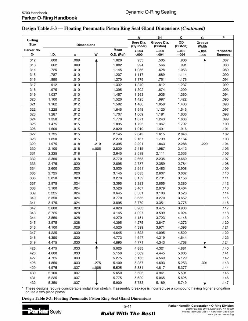
Parker O-Ring Handbook5700 Handbook Dynamic O-Ring Sealing
5-41
Build With The Best!SealsParker Hannifin Corporation • O-Ring Division
2360 Palumbo Drive, Lexington, KY 40509Phone: (859) 269-2351 • Fax: (859) 335-5128
www.parker.com/o-ring
O-RingSize
Parker No.2-
Dimensions
MeanI.D. ± W O.D. (Ref)
A
Bore Dia.(Cylinder)
+.004-.000
B-1
Groove Dia.(Piston)
+.000-.004
C
OD(Piston)
+.000-.004
GGrooveWidth
+.004-.000
P
PeripheralSqueeze
312 .600 .009 1.020 .933 .505 .930 .087313 .662 .009 1.082 .994 .566 .991 .088314 .725 .010 1.145 1.056 .628 1.053 .089315 .787 .010 1.207 1.117 .689 1.114 .090316 .850 .010 1.270 1.179 .751 1.176 .091
317 .912 .010 1.332 1.240 .812 1.237 .092318 .975 .010 1.395 1.302 .874 1.299 .093319 1.037 .010 1.457 1.363 .935 1.360 .094320 1.100 .012 1.520 1.425 .997 1.422 .095321 1.162 .012 1.582 1.486 1.058 1.483 .096
322 1.225 .012 1.645 1.548 1.120 1.545 .097323 1.287 .012 1.707 1.609 1.181 1.636 .098324 1.350 .012 1.770 1.671 1.243 1.668 .099325 1.475 .015 1.895 1.795 1.367 1.792 .100326 1.600 .015 2.020 1.919 1.491 1.916 .101
327 1.725 .015 2.145 2.043 1.615 2.040 .102328 1.850 .015 2.270 2.167 1.739 2.164 .103329 1.975 .018 .210 2.395 2.291 1.863 2.288 .229 .104330 2.100 .018 ±.005 2.520 2.415 1.987 2.412 .105331 2.225 .018 2.645 2.539 2.111 2.536 .106
332 2.350 .018 2.770 2.663 2.235 2.660 .107333 2.475 .020 2.895 2.787 2.359 2.784 .108334 2.600 .020 3.020 2.991 2.483 2.908 .109335 2.725 .020 3.145 3.035 2.607 3.032 .110336 2.850 .020 3.270 3.159 2.731 3.156 .111
337 2.975 .024 3.395 3.283 2.855 3.280 .112338 3.100 .024 3.520 3.407 2.979 3.404 .113339 3.225 .024 3.645 3.531 3.103 3.528 .114340 3.350 .024 3.770 3.655 3.270 3.652 .115341 3.475 .024 3.895 3.779 3.351 3.776 .116
342 3.600 .028 4.020 3.903 3.475 3.900 .117343 3.725 .028 4.145 4.027 3.599 4.024 .118344 3.850 .028 4.270 4.151 3.723 4.148 .119345 3.975 .028 4.395 4.275 3.847 4.272 .120346 4.100 .028 4.520 4.399 3.971 4.396 .121
347 4.225 .030 4.645 4.523 4.095 4.520 .122348 4.350 .030 4.773 4.647 4.219 4.644 .123349 4.475 .030 4.895 4.771 4.343 4.768 .124
425 4.475 .033 5.025 4.885 4.321 4.881 .140426 4.600 .033 5.150 5.009 4.445 5.005 .141427 4.725 .033 5.275 5.133 4.569 5.129 .142428 4.850 .033 .275 5.400 5.257 4.693 5.253 .301 .143429 4.975 .037 ±.006 5.525 5.381 4.817 5.377 .144
430 5.100 .037 5.650 5.505 4.941 5.501 .145431 5.225 .037 5.775 5.629 5.065 5.625 .146432 5.350 .037 5.900 5.753 5.189 5.749 .147
* These designs require considerable installation stretch. If assembly breakage is incurred use a compound having higher elongationor use a two-piece piston.
Design Table 5-3 — Floating Pneumatic Piston Ring Seal Gland Dimensions (Continued)
Design Table 5-3: Floating Pneumatic Piston Ring Seal Gland Dimensions
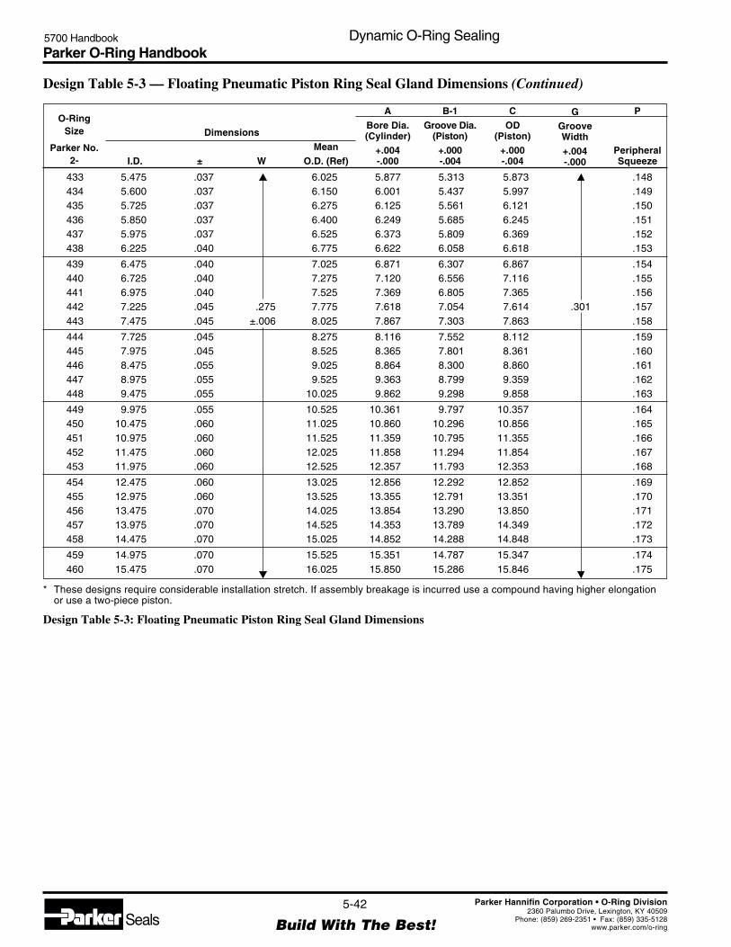
Parker O-Ring Handbook5700 Handbook Dynamic O-Ring Sealing
5-42
Build With The Best!SealsParker Hannifin Corporation • O-Ring Division
2360 Palumbo Drive, Lexington, KY 40509Phone: (859) 269-2351 • Fax: (859) 335-5128
www.parker.com/o-ring
O-RingSize
Parker No.2-
Dimensions
MeanI.D. ± W O.D. (Ref)
A
Bore Dia.(Cylinder)
+.004-.000
B-1
Groove Dia.(Piston)
+.000-.004
C
OD(Piston)
+.000-.004
GGrooveWidth
+.004-.000
P
PeripheralSqueeze
433 5.475 .037 6.025 5.877 5.313 5.873 .148434 5.600 .037 6.150 6.001 5.437 5.997 .149435 5.725 .037 6.275 6.125 5.561 6.121 .150436 5.850 .037 6.400 6.249 5.685 6.245 .151437 5.975 .037 6.525 6.373 5.809 6.369 .152438 6.225 .040 6.775 6.622 6.058 6.618 .153
439 6.475 .040 7.025 6.871 6.307 6.867 .154440 6.725 .040 7.275 7.120 6.556 7.116 .155441 6.975 .040 7.525 7.369 6.805 7.365 .156442 7.225 .045 .275 7.775 7.618 7.054 7.614 .301 .157443 7.475 .045 ±.006 8.025 7.867 7.303 7.863 .158
444 7.725 .045 8.275 8.116 7.552 8.112 .159445 7.975 .045 8.525 8.365 7.801 8.361 .160446 8.475 .055 9.025 8.864 8.300 8.860 .161447 8.975 .055 9.525 9.363 8.799 9.359 .162448 9.475 .055 10.025 9.862 9.298 9.858 .163
449 9.975 .055 10.525 10.361 9.797 10.357 .164450 10.475 .060 11.025 10.860 10.296 10.856 .165451 10.975 .060 11.525 11.359 10.795 11.355 .166452 11.475 .060 12.025 11.858 11.294 11.854 .167453 11.975 .060 12.525 12.357 11.793 12.353 .168
454 12.475 .060 13.025 12.856 12.292 12.852 .169455 12.975 .060 13.525 13.355 12.791 13.351 .170456 13.475 .070 14.025 13.854 13.290 13.850 .171457 13.975 .070 14.525 14.353 13.789 14.349 .172458 14.475 .070 15.025 14.852 14.288 14.848 .173
459 14.975 .070 15.525 15.351 14.787 15.347 .174460 15.475 .070 16.025 15.850 15.286 15.846 .175
* These designs require considerable installation stretch. If assembly breakage is incurred use a compound having higher elongationor use a two-piece piston.
Design Table 5-3 — Floating Pneumatic Piston Ring Seal Gland Dimensions (Continued)
Design Table 5-3: Floating Pneumatic Piston Ring Seal Gland Dimensions

Parker O-Ring Handbook5700 Handbook Dynamic O-Ring Sealing
5-43
Build With The Best!SealsParker Hannifin Corporation • O-Ring Division
2360 Palumbo Drive, Lexington, KY 40509Phone: (859) 269-2351 • Fax: (859) 335-5128
www.parker.com/o-ring
5.30.4 O-Ring Glands for Rotary Seals
Design Chart 5-4 provides the basis for calculating gland dimensions. For standard O-ring sizes, these dimensions havebeen calculated and are listed in Design Table 5-4. The procedures for the use of Design Table 5-4 are outlined in DesignGuide 5-4 below.
Guide For Design Table 5-4
Select Closest ReadIf Desired Dimension Dimension Horizontally To Determine
Is Known For In Column In Column Dimension For
A-1 Groove Dia. for shaftOD of shaft B D Throat Dia.
G Groove width
A-1 Groove Dia. for shaftThroat Dia. D B OD of shaft
G Groove width
Design Guide 5-4: Guide For Design Table 5-4
After selecting gland dimensions, read horizontally to determine proper O-ring size number.Specify compound. Refer to the discussion on rotary seals earlier in this chapter for theselection of the proper compound The effective part number for an O-ring consists of both asize number and a compound number.

Parker O-Ring Handbook5700 Handbook Dynamic O-Ring Sealing
5-44
Build With The Best!SealsParker Hannifin Corporation • O-Ring Division
2360 Palumbo Drive, Lexington, KY 40509Phone: (859) 269-2351 • Fax: (859) 335-5128
www.parker.com/o-ring
Design Chart 5-4 Rotary O-Ring Seal Glands, 55.2 Bar (800 PSI) Max.
See Rotary Seal discussion in Dynamic Seals section before using this chart.
Note: Due to effect of centrifugal force, do not locate groove in shaft. Refer to Design Chart 5-4 (below) and Design Table 5-4 fordimensions.
O-Ring W MSize Cross Section Maximum Squeeze L G E (c) Eccen- Bearing R
Parker Speed Gland Groove Diametral tricity Length GrooveNo. 2- Nominal Actual FPM (a) % Depth Width Clearance Max (b) Min. (c) Radius
004 0.065 0.075 0.012 0.005through 1/16
0.070200— 0-11 to to to 0.002 0.700 to
045±.003
1500 0.067 0.079 0.016 0.015102 0.097 0.108 0.012 0.005
through 3/32 0.103 200— 1-8 1/2 to to to 0.002 1.030 to163 ±.003 600 0.099 0.112 0.016 0.015201 0.133 0.144 0.016 0.010
through 1/8 0.139 200— 0-7 to to to 0.003 1.390 to258 ±.004 400 0.135 0.148 0.020 0.025
(a) Feet per minute = 0.26 X Shaft Diameter (inches) X rpm.(b) Total indicator reading between groove OD, shaft, and adjacent bearing surface.(c) If clearance (extrusion gap) must be reduced for higher pressures, bearing length M must be no less than the minimum figures
given. Clearances given are based on the use of 80 shore durometer minimum O-ring for 55.2 Bar (800 PSI) max. See Figure 3-2 forrecommended clearances when pressures exceed 55.2 Bar (800 PSI).
Design Chart 5-4: Design Chart for Rotary O-Ring Seal Glands
Design Chart 5-4 — Rotary O-Ring Seal Glands, 55.2 Bar (800 PSI) Max. (c)(Below 200 FPM, Use Design Chart 5-2)
Finishes are RMS values
Locate Seal as Close asPossible to Lubricating Fluid
Pressure
M
B Dia. = O-ring I.D. + .002
D Dia.(D Min. = B Max. + E Min.)
16 Max. 1/2 E
Gland Detail
1/2 E
F L
G
R
16
32
32 32
0° to 5° Typ.(0° Preferred)
Break EdgesApprox. .005 Rad.
GlandDepth
F GrooveDepth (Ref.)
A-1 Dia.(A-1 Min. = B Max. + 2L Min.)
.005Typ.
W
WW
W
I.D.
.003 Typ.
Section W-W

Parker O-Ring Handbook5700 Handbook Dynamic O-Ring Sealing
5-45
Build With The Best!SealsParker Hannifin Corporation • O-Ring Division
2360 Palumbo Drive, Lexington, KY 40509Phone: (859) 269-2351 • Fax: (859) 335-5128
www.parker.com/o-ring
Table 5-4 — Rotary O-Ring Seal Gland Dimensions
004 .070 .005 .210 .072 .202 .084005 .101 .005 .241 .103 .233 .115006 .114 .005 .254 .116 .246 .128007 .145 .005 .285 .147 .277 .159008 .176 .005 .316 .178 .308 .190
009 .208 .005 .348 .210 .340 .222010 .239 .005 .379 .241 .371 .253011 .301 .005 .441 .303 .433 .315012 .364 .005 .504 .366 .496 .378013 .426 .005 .566 .428 .558 .440
014 .489 .005 .629 .491 .621 .503015 .551 .007 .691 .553 .683 .565016 .614 .009 .754 .616 .746 .628017 .676 .009 .816 .678 .808 .693018 .739 .009 .070 .879 .741 .871 .753 .075
019 .801 .009 ±.003 .941 .803 .933 .815020 .864 .009 1.004 .866 .996 .878021 .926 .009 1.066 .928 1.058 .940022 .989 .010 1.129 .991 1.121 1.003023 1.051 .010 1.191 1.053 1.183 1.065
024 1.114 .010 1.254 1.116 1.246 1.128025 1.176 .011 1.316 1.178 1.308 1.190026 1.239 .011 1.379 1.241 1.371 1.253027 1.301 .011 1.441 1.303 1.433 1.315028 1.364 .013 1.504 1.366 1.496 1.378
029 1.489 .013 1.629 1.491 1.621 1.503030 1.614 .013 1.754 1.616 1.746 1.628031 1.739 .015 1.879 1.741 1.871 1.753032 1.864 .015 2.004 1.866 1.996 1.878033 1.989 .018 2.129 1.991 2.121 2.003
034 2.114 .018 2.254 2.116 2.246 2.128035 2.239 .018 2.379 2.241 2.371 2.253036 2.364 .018 2.504 2.366 2.496 2.378037 2.489 .018 2.629 2.491 2.621 2.503038 2.614 .020 2.754 2.616 2.746 2.628
039 2.739 .020 2.879 2.741 2.871 2.753040 2.864 .020 3.004 2.866 2.996 2.878041 2.989 .024 3.129 2.991 3.121 3.003042 3.239 .024 3.379 3.241 3.371 3.253043 3.489 .024 3.629 3.491 3.621 3.503
044 3.739 .027 3.879 3.741 3.871 3.753045 3.989 .027 4.129 3.991 4.121 4.003
102 .049 .005 .255 .051 .245 .063103 .081 .005 .103 .287 .083 .277 .095 .108104 .112 .005 ±.003 .318 .114 .308 .126105 .143 .005 .349 .145 .339 .157106 .174 .005 .380 .176 .370 .188
O-RingSize
Parker No.2-
DimensionsMean
I.D. ± W O.D. (Ref)
BOD
(Shaft)+.000-.001
A-1Groove Dia.
(Gland)+.003-.000
DThroat
Dia.+.003-.000
GGrooveWidth+.004-.000
† For pressures over 55.2 Bar (800 PSI), consult Design Chart 5-4 and the design sections of this Handbook.
Design Table 5-4: Rotary O-Ring Seal Gland Dimensions
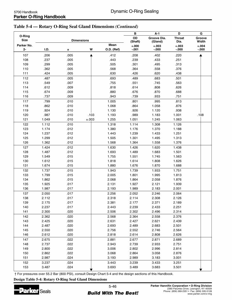
Parker O-Ring Handbook5700 Handbook Dynamic O-Ring Sealing
5-46
Build With The Best!SealsParker Hannifin Corporation • O-Ring Division
2360 Palumbo Drive, Lexington, KY 40509Phone: (859) 269-2351 • Fax: (859) 335-5128
www.parker.com/o-ring
Table 5-4 — Rotary O-Ring Seal Gland Dimensions (Continued)
107 .206 .005 .412 .208 .402 .220108 .237 .005 .443 .239 .433 .251109 .299 .005 .505 .301 .495 .313110 .362 .005 .568 .364 .558 .376111 .424 .005 .630 .426 .620 .438
112 .487 .005 .693 .489 .683 .501113 .549 .007 .755 .551 .745 .563114 .612 .009 .818 .614 .808 .626115 .674 .009 .880 .676 .870 .688116 .737 .009 .943 .739 .933 .751
117 .799 .010 1.005 .801 .995 .813118 .862 .010 1.068 .864 1.058 .876119 .924 .010 1.130 .926 1.120 .938120 .987 .010 .103 1.193 .989 1.183 1.001 .108121 1.049 .010 ±.003 1.255 1.051 1.245 1.063
122 1.112 .010 1.318 1.114 1.308 1.126123 1.174 .012 1.380 1.176 1.370 1.188124 1.237 .012 1.443 1.239 1.433 1.251125 1.299 .012 1.505 1.301 1.495 1.313126 1.362 .012 1.568 1.364 1.558 1.376
127 1.424 .012 1.630 1.426 1.620 1.438128 1.487 .012 1.693 1.489 1.683 1.501129 1.549 .015 1.755 1.551 1.745 1.563130 1.612 .015 1.818 1.614 1.808 1.626131 1.674 .015 1.880 1.676 1.870 1.688
132 1.737 .015 1.943 1.739 1.933 1.751133 1.799 .015 2.005 1.801 1.995 1.813134 1.862 .015 2.068 1.864 2.058 1.876135 1.925 .017 2.131 1.927 2.121 1.939136 1.987 .017 2.193 1.989 2.183 2.001
137 2.050 .017 2.256 2.052 2.246 2.064138 2.112 .017 2.318 2.114 2.308 2.126139 2.175 .017 2.381 2.177 2.371 2.189140 2.237 .017 2.443 2.239 2.433 2.251141 2.300 .020 2.506 2.302 2.496 2.314
142 2.362 .020 2.568 2.364 2.558 2.376143 2.425 .020 2.631 2.427 2.621 2.439144 2.487 .020 2.693 2.489 2.683 2.501145 2.550 .020 2.756 2.552 2.746 2.564146 2.612 .020 2.818 2.614 2.808 2.626
147 2.675 .022 2.881 2.677 2.871 2.689148 2.737 .022 2.943 2.739 2.933 2.751149 2.800 .022 3.006 2.802 2.996 2.814150 2.862 .022 3.068 2.864 3.058 2.876151 2.987 .024 3.193 2.989 3.183 3.001
152 3.237 .024 3.443 3.239 3.433 3.251153 3.487 .024 3.693 3.489 3.683 3.501
O-RingSize
Parker No.2-
DimensionsMean
I.D. ± W O.D. (Ref)
BOD
(Shaft)+.000-.001
A-1Groove Dia.
(Gland)+.003-.000
DThroat
Dia.+.003-.000
GGrooveWidth+.004-.000
† For pressures over 55.2 Bar (800 PSI), consult Design Chart 5-4 and the design sections of this Handbook.
Design Table 5-4: Rotary O-Ring Seal Gland Dimensions
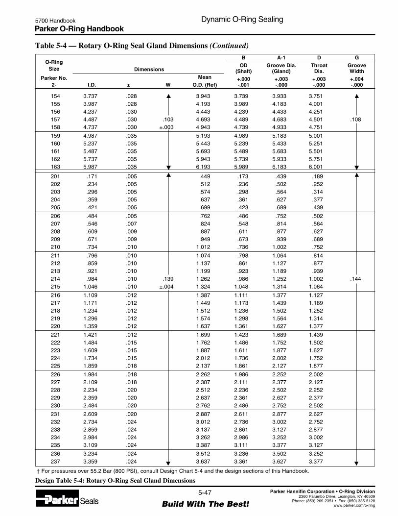
Parker O-Ring Handbook5700 Handbook Dynamic O-Ring Sealing
5-47
Build With The Best!SealsParker Hannifin Corporation • O-Ring Division
2360 Palumbo Drive, Lexington, KY 40509Phone: (859) 269-2351 • Fax: (859) 335-5128
www.parker.com/o-ring
154 3.737 .028 3.943 3.739 3.933 3.751155 3.987 .028 4.193 3.989 4.183 4.001156 4.237 .030 4.443 4.239 4.433 4.251157 4.487 .030 .103 4.693 4.489 4.683 4.501 .108158 4.737 .030 ±.003 4.943 4.739 4.933 4.751
159 4.987 .035 5.193 4.989 5.183 5.001160 5.237 .035 5.443 5.239 5.433 5.251161 5.487 .035 5.693 5.489 5.683 5.501162 5.737 .035 5.943 5.739 5.933 5.751163 5.987 .035 6.193 5.989 6.183 6.001
201 .171 .005 .449 .173 .439 .189202 .234 .005 .512 .236 .502 .252203 .296 .005 .574 .298 .564 .314204 .359 .005 .637 .361 .627 .377205 .421 .005 .699 .423 .689 .439
206 .484 .005 .762 .486 .752 .502207 .546 .007 .824 .548 .814 .564208 .609 .009 .887 .611 .877 .627209 .671 .009 .949 .673 .939 .689210 .734 .010 1.012 .736 1.002 .752
211 .796 .010 1.074 .798 1.064 .814212 .859 .010 1.137 .861 1.127 .877213 .921 .010 1.199 .923 1.189 .939214 .984 .010 .139 1.262 .986 1.252 1.002 .144215 1.046 .010 ±.004 1.324 1.048 1.314 1.064
216 1.109 .012 1.387 1.111 1.377 1.127217 1.171 .012 1.449 1.173 1.439 1.189218 1.234 .012 1.512 1.236 1.502 1.252219 1.296 .012 1.574 1.298 1.564 1.314220 1.359 .012 1.637 1.361 1.627 1.377
221 1.421 .012 1.699 1.423 1.689 1.439222 1.484 .015 1.762 1.486 1.752 1.502223 1.609 .015 1.887 1.611 1.877 1.627224 1.734 .015 2.012 1.736 2.002 1.752225 1.859 .018 2.137 1.861 2.127 1.877
226 1.984 .018 2.262 1.986 2.252 2.002227 2.109 .018 2.387 2.111 2.377 2.127228 2.234 .020 2.512 2.236 2.502 2.252229 2.359 .020 2.637 2.361 2.627 2.377230 2.484 .020 2.762 2.486 2.752 2.502
231 2.609 .020 2.887 2.611 2.877 2.627232 2.734 .024 3.012 2.736 3.002 2.752233 2.859 .024 3.137 2.861 3.127 2.877234 2.984 .024 3.262 2.986 3.252 3.002235 3.109 .024 3.387 3.111 3.377 3.127
236 3.234 .024 3.512 3.236 3.502 3.252237 3.359 .024 3.637 3.361 3.627 3.377
O-RingSize
Parker No.2-
DimensionsMean
I.D. ± W O.D. (Ref)
BOD
(Shaft)+.000-.001
A-1Groove Dia.
(Gland)+.003-.000
DThroat
Dia.+.003-.000
GGrooveWidth+.004-.000
† For pressures over 55.2 Bar (800 PSI), consult Design Chart 5-4 and the design sections of this Handbook.
Table 5-4 — Rotary O-Ring Seal Gland Dimensions (Continued)
Design Table 5-4: Rotary O-Ring Seal Gland Dimensions

Parker O-Ring Handbook5700 Handbook Dynamic O-Ring Sealing
5-48
Build With The Best!SealsParker Hannifin Corporation • O-Ring Division
2360 Palumbo Drive, Lexington, KY 40509Phone: (859) 269-2351 • Fax: (859) 335-5128
www.parker.com/o-ring
O-RingSize
Parker No.2-
DimensionsMean
I.D. ± W O.D. (Ref)
BOD
(Shaft)+.000-.001
A-1Groove Dia.
(Gland)+.003-.000
DThroat
Dia.+.003-.000
GGrooveWidth+.004-.000
† For pressures over 55.2 Bar (800 PSI), consult Design Chart 5-4 and the design sections of this Handbook.
238 3.484 .024 3.762 3.486 3.752 3.502239 3.609 .028 3.887 3.611 3.877 3.627240 3.734 .028 4.012 3.736 4.002 3.752241 3.859 .028 4.137 3.861 4.127 3.877242 3.984 .028 4.262 3.986 4.252 4.002
243 4.109 .028 4.387 4.111 4.377 4.127244 4.234 .030 4.512 4.236 4.502 4.252245 4.359 .030 4.637 4.361 4.627 4.377246 4.484 .030 .139 4.762 4.486 4.752 4.502 .144247 4.609 .030 ±.004 4.887 4.611 4.877 4.627
248 4.734 .030 5.012 4.736 5.002 4.752249 4.859 .035 5.137 4.861 5.127 4.877250 4.984 .035 5.262 4.986 5.252 5.002251 5.109 .035 5.387 5.111 5.377 5.127252 5.234 .035 5.512 5.236 5.502 5.252
253 5.359 .035 5.637 5.361 5.627 5.377254 5.484 .035 5.762 5.486 5.752 5.502255 5.609 .035 5.887 5.611 5.877 5.627256 5.734 .035 6.012 5.736 6.002 5.752257 5.859 .035 6.137 5.861 6.127 5.877
258 5.984 .035 6.262 5.986 6.252 6.002
Table 5-4 — Rotary O-Ring Seal Gland Dimensions (Continued)
Design Table 5-4: Rotary O-Ring Seal Gland Dimensions
5.31 Dynamic Vacuum Sealing
There is very little data available on dynamic vacuum seals, but reasonably low leak rates have been reported using twoO-rings seals designed according to the standard radial dynamic design dimensions for reciprocating seals which areshown in Design Chart 5-5.
In sealing gases and vacuum, it is quite feasible to use two O-ring seals in separate grooves. (In reciprocating hydraulicapplications, however, such redundant seals are not recommended because of the danger of creating a pressure trapbetween the two seals.)
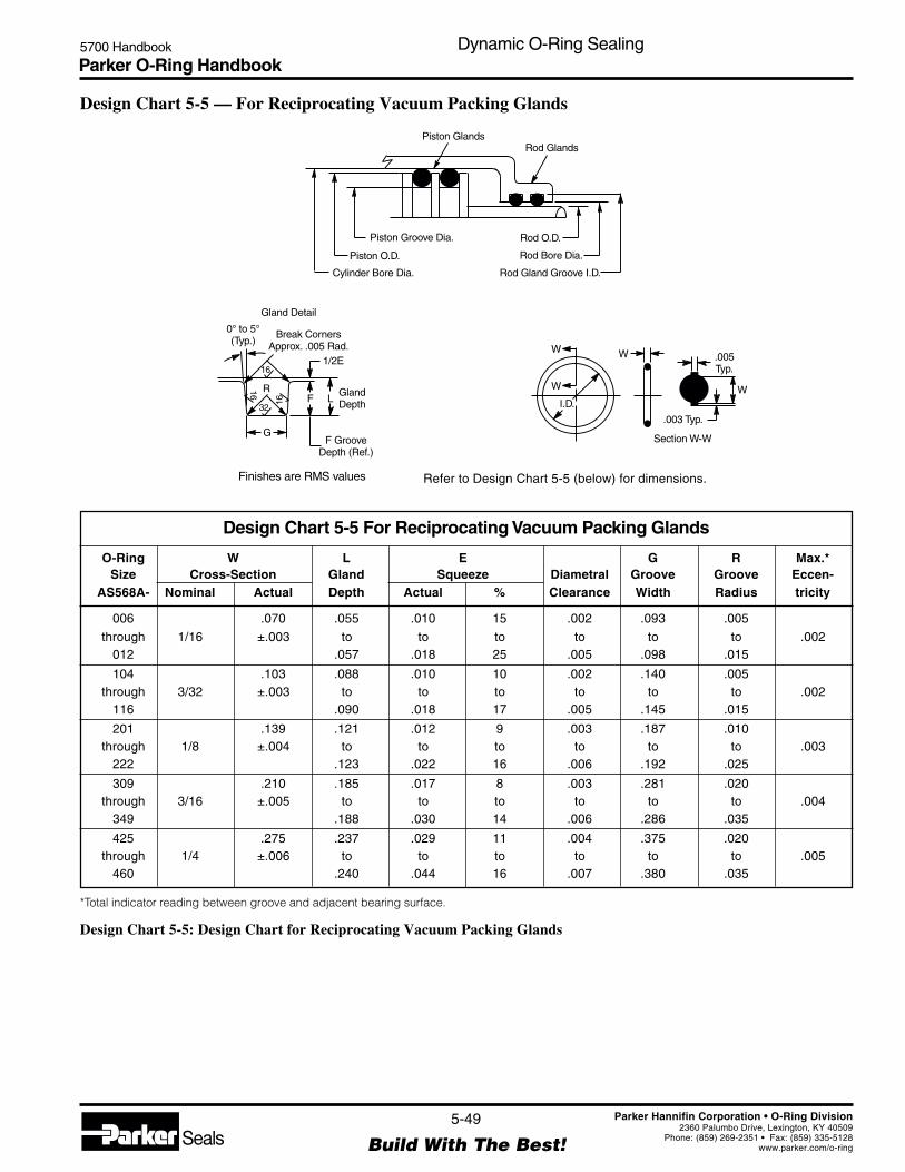
Parker O-Ring Handbook5700 Handbook Dynamic O-Ring Sealing
5-49
Build With The Best!SealsParker Hannifin Corporation • O-Ring Division
2360 Palumbo Drive, Lexington, KY 40509Phone: (859) 269-2351 • Fax: (859) 335-5128
www.parker.com/o-ring
Design Chart 5-5 — For Reciprocating Vacuum Packing Glands
Refer to Design Chart 5-5 (below) for dimensions.
O-Ring W L E G R Max.*Size Cross-Section Gland Squeeze Diametral Groove Groove Eccen-
AS568A- Nominal Actual Depth Actual % Clearance Width Radius tricity
006 .070 .055 .010 15 .002 .093 .005
through 1/16 ±.003 to to to to to to .002012 .057 .018 25 .005 .098 .015
104 .103 .088 .010 10 .002 .140 .005through 3/32 ±.003 to to to to to to .002
116 .090 .018 17 .005 .145 .015
201 .139 .121 .012 9 .003 .187 .010through 1/8 ±.004 to to to to to to .003
222 .123 .022 16 .006 .192 .025
309 .210 .185 .017 8 .003 .281 .020through 3/16 ±.005 to to to to to to .004
349 .188 .030 14 .006 .286 .035
425 .275 .237 .029 11 .004 .375 .020through 1/4 ±.006 to to to to to to .005
460 .240 .044 16 .007 .380 .035
Design Chart 5-5 For Reciprocating Vacuum Packing Glands
*Total indicator reading between groove and adjacent bearing surface.
Design Chart 5-5: Design Chart for Reciprocating Vacuum Packing Glands
Piston GlandsRod Glands
Rod O.D.Piston Groove Dia.
Rod Bore Dia.Piston O.D.
Rod Gland Groove I.D.Cylinder Bore Dia.
Gland Detail
1/2E
F L
G
R
16
16
32
16
0° to 5°(Typ.)
Break CornersApprox. .005 Rad.
GlandDepth
F GrooveDepth (Ref.)
.005Typ.
W
WW
W
I.D.
.003 Typ.
Section W-W
Finishes are RMS values
Parker O-Ring Handbook5700 Handbook Back-Up Rings
6-1
Build With The Best!SealsParker Hannifin Corporation • O-Ring Division
2360 Palumbo Drive, Lexington, KY 40509Phone: (859) 269-2351 • Fax: (859) 335-5128
www.parker.com/o-ring
Section VIBack-Up Rings
6.1 Introduction ............................................................................................................................................. 6-2
6.2 Anti-Extrusion Device Design Hints ...................................................................................................... 6-2
6.3 Parbak® Elastomer Back-Up Rings ......................................................................................................... 6-2
6.4 Other Back-Up Ring Materials ............................................................................................................... 6-3
6.4.1 Polytetrafluoroethylene (PTFE) Back-Up Rings .......................................................................... 6-3
6.4.2 Metal Non-Extrusion Rings........................................................................................................... 6-3
6.4.3 Leather Back-Up Rings ................................................................................................................. 6-3
6.5 Parbak Compound Information ............................................................................................................... 6-3
6.6 Parker Parbak 8-Series Dimensions ........................................................................................................ 6-3
Parbak® is a registered trademark of Parker Hannifin Corporation.

Parker O-Ring Handbook5700 Handbook Back-Up Rings
6-2
Build With The Best!SealsParker Hannifin Corporation • O-Ring Division
2360 Palumbo Drive, Lexington, KY 40509Phone: (859) 269-2351 • Fax: (859) 335-5128
www.parker.com/o-ring
6.1 Introduction
Parbak® back-up rings offered by Parker Seal help preventextrusion in high pressure service or compensate for loosefitting parts. The use of loose fitting parts makes for costreduction in the machining of unit components.
The 90 durometer curve in Figure 3-2 may be used to findthe maximum recommended clearance at a given pressurefor temperatures up to 74°C (165°F) when standard Parbakrings in Parker’s N0300-90 nitrile compound are used toprotect an O-ring from extrusion. In using these curves, itmust be remembered that cylinders tend to expand whenpressurized. The clearance that the Parbak will see is theclearance between the piston and the expanded cylinder.
The extrusion curves can be used in two different ways toreap the benefits of Parbaks, depending on the application.In low pressure seals, the curves will indicate wider permis-sible clearances than those given in the design charts.Tolerances on these can be opened up until they permitthese larger clearances to occur, resulting in substantialmachining economies. When tolerances are increased, how-ever, one must check to be sure that squeeze values cannotbecome too high or too low.
In high pressure applications, the curves will indicatewhether adding a Parbak will permit the use of standardcatalog gland dimensions or whether the clearance willneed to be reduced further.
In double acting seal assemblies, a Parbak is required onboth sides of the O-ring. It is cheap insurance to use twoParbaks even in single acting installations. At assembly, itis too easy to place a single Parbak on the wrong side of theO-ring. By specifying one on each side of the O-ring, therewill be one on the low pressure side, where it is needed, andthe extra Parbak does no harm.
Unlike many PTFE back-up rings, Parbak rings are con-tinuous; i.e. they do not have a cut because they can bestretched over the end of a piston to assemble. Hence theycontact the mating O-ring uniformly, and do not cause local-ized wear spots.
Parbaks are contoured on one face to minimize distortion ofthe O-ring when under pressure, yet the orientation of thecontoured face is immaterial to the proper function of thepart because it is flexible.
Parbaks are quick and easy to assemble, minimizing assem-bly costs, and they cannot fall out of the O-ring groove.Besides their advantages as antiextrusion devices, Parbakrings help trap lubricant, preserving the O-ring.
The standard sizes are listed in Table 6-1. Refer to theappropriate Design Chart for recommended groove width.Special sizes are also made to order.
6.2 Anti-Extrusion Device Design Hints1. Wherever possible use two back-up rings, one on
each side of the O-ring.2. If only one back-up ring is used, the O-ring should
be placed between it and the pressure.3. Parbaks may be installed with the contoured face
either against the O-ring or against the side of thegroove, but reversal does no harm.
4. Parker’s Parbaks will not “collapse” or cold flow ifused with proper groove designs.
5. Use groove widths given in the Static O-Ring Seal-ing and Dynamic O-Ring Sealing Sections.
6.3 Parbak Elastomer Back-Up Rings
Hard rubber back-up rings combine most of the best fea-tures of both leather and PTFE anti-extrusion devices.Although no industrial or military standards have beenissued for rubber back-up rings, they have been in use fora number of years. These are special devices designed tosatisfy a specific problem.
Parbaks in Parker Seal Group’s standard nitrile compound,N0300-90, are generally usable through a temperaturerange of -55°C to 120°C (-65° to 250°F).
Features of Parbak Rings1. Elastic memory permits Parbak rings to be stretched
into place for assembly without preconditioning orcutting.
2. Continuous construction prevents damage to theO-ring seal.
3. Lubrication is enhanced by rubber which absorbssystem fluid and does not plate out on rubbing surfaces.
Parbak is a Parker standard rubber back-up ring ofcontoured design. It is intended for use in dynamic andstatic seal applications, in O-ring glands depicted in thetables in the Static O-Ring Sealing and Dynamic O-RingSealing Sections. When used in standard static glands, agenerous lead-in chamfer and lubrication are particularlyimportant to facilitate assembly. In some cases increasedgland depth may be appropriate.
Back-Up RingsBack-Up RingsBack-Up RingsBack-Up RingsBack-Up Rings
Parbak® is a registered trademark of Parker Hannifin Corporation.

Parker O-Ring Handbook5700 Handbook Back-Up Rings
6-3
Build With The Best!SealsParker Hannifin Corporation • O-Ring Division
2360 Palumbo Drive, Lexington, KY 40509Phone: (859) 269-2351 • Fax: (859) 335-5128
www.parker.com/o-ring
6.4 Other Back-Up Ring Materials
6.4.1 Polytetrafluoroethylene (PTFE) Back-UpRingsAnti-extrusion rings made from tetrafluoroethylene areimpervious to oils and solvents. Acids and inorganic saltshave very little effect on PTFE resin. In addition to its goodchemical resistance, PTFE may be used over a wide tem-perature range, from below -73°C to over 204°C (-100°F toover 400°F). Thus, PTFE back-up rings may be used withmost elastomeric O-ring seals. For installation, PTFE back-up rings are supplied either scarf or spiral cut as shown inFigure 6-1. These discontinuities may contribute to sealdamage due to biting and pinching. PTFE can also impairseal lubrication by plating rubbing surfaces with PTFEresin to which lubricating oil will not adhere.
6.4.2 Metal Non-Extrusion RingsIn most cases it will be impracticable and unnecessary(under 1380 bar; 20,000 PSI) to design bolt and rivet sealglands that are self-tightening, i.e., tending to reduce ratherthan increase seal extrusion clearance as pressure increases.Adequate gland volume should be allowed, in keeping withassembly tolerances. Two designs that have been helpful inalleviating extrusion of bolt and similar ultra high pressureseals are shown in Figure 6-2.
6.4.3 Leather Back-Up RingsLeather has been a standard back-up ring material for manyyears. Manufacturers of these rings have developed specialprocessing methods and impregnations for different typesof applications. Standard sizes have been established foruse with all standard O-rings. If there is any questionconcerning the suitability of leather for the application,consult the supplier. Leather back-up rings are manufac-tured as continuous rings and in most cases must be stretchedduring installation. Less damage will be incurred to theback-up rings if they are soaked in oil before installation.After installation, a short exposure to heat will shrink theleather rings back to size. Leather back-up rings shouldnever be cut to facilitate installation.
6.5 Parbak Compound Information
Some back-up ring materials tend to leave deposits in themicro fine grooves of the surface on which they rub. An
ultra smooth, wax-like surface results. Because an O-ringmay wipe all lubrication from such a surface, reversestroking is dry and greatly reduces seal life. Parbaks ofN0300-90 and other rubber compounds solve this problem.They do not leave a deposit on the metal surface, thuslubrication remains.
The standard compound for Parbaks is N0300-90. Carefulengineering and research has produced N0300-90 whichhas the best combination of characteristics for the majorityof back-up ring installations — broad temperature range,proper hardness, long sealing life, and resistance to a greatnumber of fluids. It is resistant to nearly all hydraulic fluidsexcept certain of the non-flammable types such as Skydrol.It is also resistant to air and water.
The recommended temperature range for N0300-90 is from-40°C to 121°C (-40°F to 250°F).
Functional tests have proven that millions of cycles can beobtained with Parbaks, showing their tremendous superior-ity over the older types of back-up rings.
In addition to N0300-90, Parker Seal has developed othercompounds for installations requiring special characteris-tics. Present capabilities include service at continuoustemperatures as high as 204°C (400°F).
Additional assistance in specifing and using Parbak rings isavailable upon request by calling your Parker Seal repre-sentative.
6.6 Parker Parbak 8-Series DimensionsDeveloped primarily for service in petroleum base hydrau-lic fluids, at -40°C to 121°C (-40°F to 250°F), Parker’sstandard Parbak compound N0300-90 provides the maxi-mum benefits in back-up ring service. Compounds for usein other fluids and for temperatures up to 204°C (400°F) areavailable on request.
Parbaks will stretch up to 50%, and are quickly and easilyinstalled. Advantages of the contour design are obtainedregardless of how Parbaks are installed. They may beinstalled with the concave face in either direction, towardor away from the O-ring.
Table 6-1 provides Parker Parbak 8-Series Dimensions.
Figure 6-1: Typical Back-Up Rings
Scarf Cut Spiral Parbak
Figure 6-2: Clearance Control for High Pressure Seals
Thin Metal Section Will ExpandDue to Pressure and MaintainMetal-to-Metal Fit
7° to 10°Soft Metal Anti-Extrusion Wedge Ring
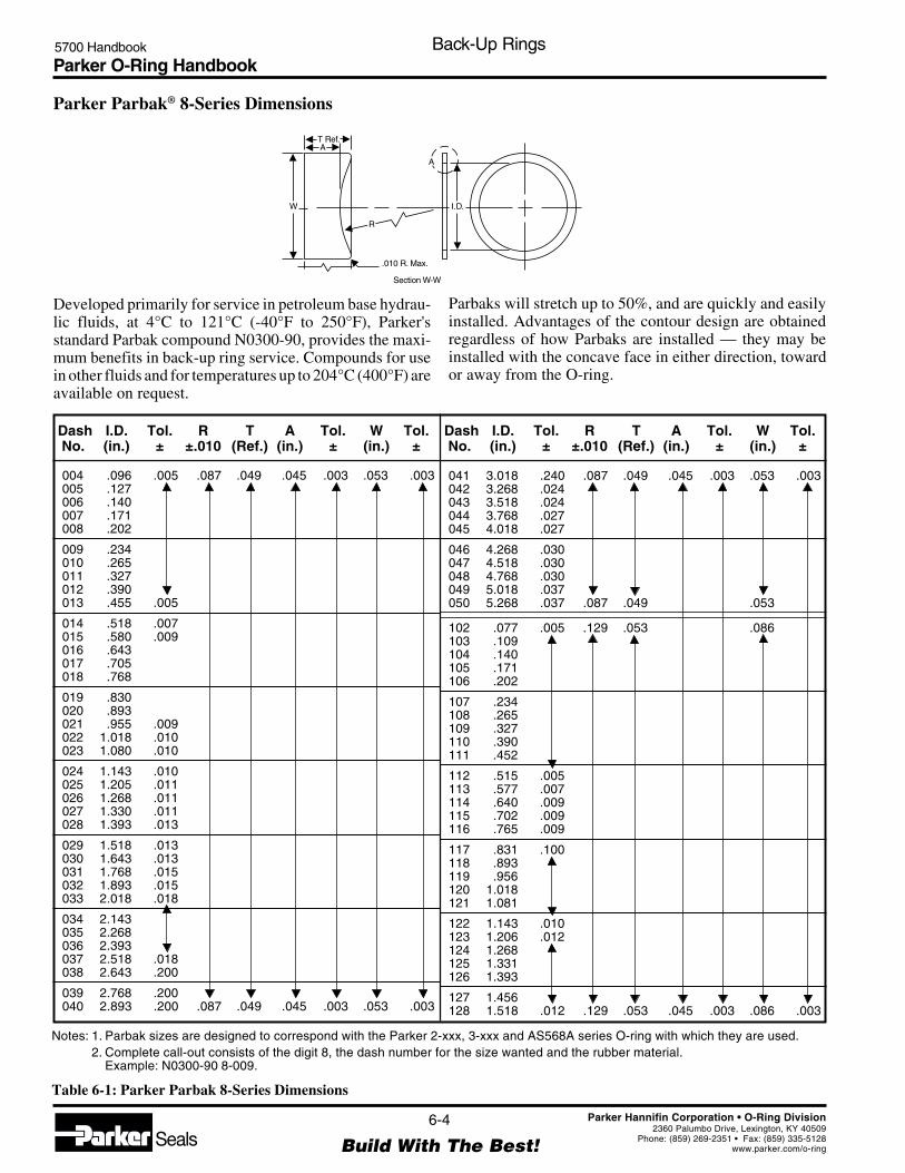
Parker O-Ring Handbook5700 Handbook Back-Up Rings
6-4
Build With The Best!SealsParker Hannifin Corporation • O-Ring Division
2360 Palumbo Drive, Lexington, KY 40509Phone: (859) 269-2351 • Fax: (859) 335-5128
www.parker.com/o-ring
Parker Parbak® 8-Series Dimensions
Notes: 1. Parbak sizes are designed to correspond with the Parker 2-xxx, 3-xxx and AS568A series O-ring with which they are used.2. Complete call-out consists of the digit 8, the dash number for the size wanted and the rubber material.
Example: N0300-90 8-009.
Table 6-1: Parker Parbak 8-Series Dimensions
004 .096 .005 .087 .049 .045 .003 .053 .003005 .127006 .140007 .171008 .202
009 .234010 .265011 .327012 .390013 .455 .005
014 .518 .007015 .580 .009016 .643017 .705018 .768
019 .830020 .893021 .955 .009022 1.018 .010023 1.080 .010
024 1.143 .010025 1.205 .011026 1.268 .011027 1.330 .011028 1.393 .013
029 1.518 .013030 1.643 .013031 1.768 .015032 1.893 .015033 2.018 .018
034 2.143035 2.268036 2.393037 2.518 .018038 2.643 .200
039 2.768 .200040 2.893 .200 .087 .049 .045 .003 .053 .003
041 3.018 .240 .087 .049 .045 .003 .053 .003042 3.268 .024043 3.518 .024044 3.768 .027045 4.018 .027
046 4.268 .030047 4.518 .030048 4.768 .030049 5.018 .037050 5.268 .037 .087 .049 .053
102 .077 .005 .129 .053 .086103 .109104 .140105 .171106 .202
107 .234108 .265109 .327110 .390111 .452
112 .515 .005113 .577 .007114 .640 .009115 .702 .009116 .765 .009
117 .831 .100118 .893119 .956120 1.018121 1.081
122 1.143 .010123 1.206 .012124 1.268125 1.331126 1.393
127 1.456128 1.518 .012 .129 .053 .045 .003 .086 .003
Developed primarily for service in petroleum base hydrau-lic fluids, at 4°C to 121°C (-40°F to 250°F), Parker'sstandard Parbak compound N0300-90, provides the maxi-mum benefits in back-up ring service. Compounds for usein other fluids and for temperatures up to 204°C (400°F) areavailable on request.
Parbaks will stretch up to 50%, and are quickly and easilyinstalled. Advantages of the contour design are obtainedregardless of how Parbaks are installed — they may beinstalled with the concave face in either direction, towardor away from the O-ring.
Dash I.D. Tol. R T A Tol. W Tol.No. (in.) ± ±.010 (Ref.) (in.) ± (in.) ±
Dash I.D. Tol. R T A Tol. W Tol.No. (in.) ± ±.010 (Ref.) (in.) ± (in.) ±
I.D.W
T Ref.A
.010 R. Max.
Section W-W
A
R

Parker O-Ring Handbook5700 Handbook Back-Up Rings
6-5
Build With The Best!SealsParker Hannifin Corporation • O-Ring Division
2360 Palumbo Drive, Lexington, KY 40509Phone: (859) 269-2351 • Fax: (859) 335-5128
www.parker.com/o-ring
129 1.581 .015 .129 .053 .045 .003 .086 .003130 1.643131 1.706
132 1.768133 1.831 .015134 1.893 .015135 1.956 .017136 2.018
137 2.081138 2.143 .017139 2.206 .017140 2.268 .017141 2.331 .020
142 2.393143 2.456144 2.518145 2.581146 2.643 .020
147 2.706 .022148 2.768149 2.831150 2.893 .022151 3.018 .024
152 3.268 .024153 3.518 .024154 3.768 .028155 4.018 .028156 4.268 .030
157 4.518 .030158 4.768 .030159 5.018 .035160 5.268161 5.518
162 5.768163 6.018 .035164 6.268 .040165 6.518166 6.768
167 7.018 .040168 7.268 .045169 7.518170 7.768171 8.018 .045
172 8.268 .050173 8.518174 8.768175 9.018 .050176 9.268 .055
177 9.518 .055178 9.768 .055 .129 .053 .045 .086 .003
201 .202 .005 .174 .050 .040 .118 .004202 .265203 .327204 .390205 .455 .005 .174 .050 .040 .003 .118 .004
Parker Parbak® 8-Series Dimensions — Continued
Dash I.D. Tol. R T A Tol. W Tol.No. (in.) ± ±.010 (Ref.) (in.) ± (in.) ±
Dash I.D. Tol. R T A Tol. W Tol.No. (in.) ± ±.010 (Ref.) (in.) ± (in.) ±
Notes: 1. Parbak sizes are designed to correspond with the Parker 2-xxx, 3-xxx and AS568A series O-ring with which they are used.2. Complete call-out consists of the digit 8, the dash number for the size wanted and the rubber material.
Example: N0300-90 8-009.
Table 6-1: Parker Parbak 8-Series Dimensions
206 .518 .005 .174 .050 .040 .003 .118 .004207 .580 .007208 .643 .009209 .705 .009210 .766 .010
211 .828212 .891213 .953214 1.016 .010215 1.078 .010
216 1.141 .012217 1.203218 1.266219 1.334220 1.397
221 1.459 .012222 1.522 .015223 1.647 .015224 1.772 .015225 1.897 .018
226 2.022 .018227 2.147 .018228 2.272 .020229 2.397 .020230 2.522 .020
231 2.631 .020232 2.756 .024233 2.881234 3.006235 3.131
236 3.256237 3.381238 3.506 .024239 3.631 .028240 3.756
241 3.881242 4.006243 4.131 .028244 4.256 .030245 4.381
246 4.506247 4.631248 4.768 .030249 4.893 .035250 5.018
251 5.143252 5.268253 5.393254 5.518255 5.643
256 5.768257 5.893258 6.018 .035259 6.268 .040260 6.518 .040
261 6.768 .040 .174 .050 .040 .003 .118 .004
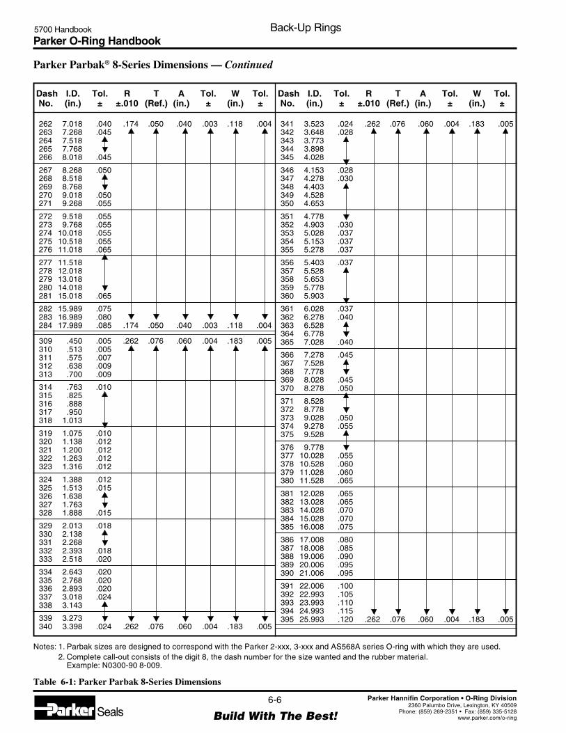
Parker O-Ring Handbook5700 Handbook Back-Up Rings
6-6
Build With The Best!SealsParker Hannifin Corporation • O-Ring Division
2360 Palumbo Drive, Lexington, KY 40509Phone: (859) 269-2351 • Fax: (859) 335-5128
www.parker.com/o-ring
262 7.018 .040 .174 .050 .040 .003 .118 .004263 7.268 .045264 7.518265 7.768266 8.018 .045
267 8.268 .050268 8.518269 8.768270 9.018 .050271 9.268 .055
272 9.518 .055273 9.768 .055274 10.018 .055275 10.518 .055276 11.018 .065
277 11.518278 12.018279 13.018280 14.018281 15.018 .065
282 15.989 .075283 16.989 .080284 17.989 .085 .174 .050 .040 .003 .118 .004
309 .450 .005 .262 .076 .060 .004 .183 .005310 .513 .005311 .575 .007312 .638 .009313 .700 .009
314 .763 .010315 .825316 .888317 .950318 1.013
319 1.075 .010320 1.138 .012321 1.200 .012322 1.263 .012323 1.316 .012
324 1.388 .012325 1.513 .015326 1.638327 1.763328 1.888 .015
329 2.013 .018330 2.138331 2.268332 2.393 .018333 2.518 .020
334 2.643 .020335 2.768 .020336 2.893 .020337 3.018 .024338 3.143
339 3.273340 3.398 .024 .262 .076 .060 .004 .183 .005
341 3.523 .024 .262 .076 .060 .004 .183 .005342 3.648 .028343 3.773344 3.898345 4.028
346 4.153 .028347 4.278 .030348 4.403349 4.528350 4.653
351 4.778352 4.903 .030353 5.028 .037354 5.153 .037355 5.278 .037
356 5.403 .037357 5.528358 5.653359 5.778360 5.903
361 6.028 .037362 6.278 .040363 6.528364 6.778365 7.028 .040
366 7.278 .045367 7.528368 7.778369 8.028 .045370 8.278 .050
371 8.528372 8.778373 9.028 .050374 9.278 .055375 9.528
376 9.778377 10.028 .055378 10.528 .060379 11.028 .060380 11.528 .065
381 12.028 .065382 13.028 .065383 14.028 .070384 15.028 .070385 16.008 .075
386 17.008 .080387 18.008 .085388 19.006 .090389 20.006 .095390 21.006 .095
391 22.006 .100392 22.993 .105393 23.993 .110394 24.993 .115395 25.993 .120 .262 .076 .060 .004 .183 .005
Parker Parbak® 8-Series Dimensions — Continued
Dash I.D. Tol. R T A Tol. W Tol.No. (in.) ± ±.010 (Ref.) (in.) ± (in.) ±
Dash I.D. Tol. R T A Tol. W Tol.No. (in.) ± ±.010 (Ref.) (in.) ± (in.) ±
Notes: 1. Parbak sizes are designed to correspond with the Parker 2-xxx, 3-xxx and AS568A series O-ring with which they are used.2. Complete call-out consists of the digit 8, the dash number for the size wanted and the rubber material.
Example: N0300-90 8-009.
Table 6-1: Parker Parbak 8-Series Dimensions

Parker O-Ring Handbook5700 Handbook Back-Up Rings
6-7
Build With The Best!SealsParker Hannifin Corporation • O-Ring Division
2360 Palumbo Drive, Lexington, KY 40509Phone: (859) 269-2351 • Fax: (859) 335-5128
www.parker.com/o-ring
425 4.551 .033 .344 .117 .096 .005 .236 .006426 4.676427 4.801428 4.926 .033429 5.051 .037
430 5.176431 5.301432 5.426433 5.551434 5.676
435 5.801436 5.926437 6.051 .037438 6.274 .040439 6.524
440 6.774441 7.024 .040442 7.274 .045443 7.524444 7.774
445 8.024 .045446 8.524 .055447 9.024448 9.524449 10.024 .055
450 10.524 .060 .344 .117 .096 .005 .236 .006
Parker Parbak® 8-Series Dimensions — Continued
Dash I.D. Tol. R T A Tol. W Tol.No. (in.) ± ±.010 (Ref.) (in.) ± (in.) ±
Dash I.D. Tol. R T A Tol. W Tol.No. (in.) ± ±.010 (Ref.) (in.) ± (in.) ±
451 11.024 .060 .344 .117 .096 .005 .236 .006452 11.524453 12.024454 12.524455 13.024 .060
456 13.524 .070457 14.024458 14.524459 15.024460 15.524 .070
461 16.004 .075462 16.504 .075463 17.004 .080464 17.504 .085465 18.004 .085
466 18.504 .085467 19.004 .090468 19.504 .090469 20.004 .095470 21.004 .095
471 22.004 .100472 23.004 .105473 24.004 .110474 25.004 .115475 26.004 .120 .344 .117 .096 .005 .236 .006
Notes: 1. Parbak sizes are designed to correspond with the Parker 2-xxx, 3-xxx and AS568A series O-ring with which they are used.2. Complete call-out consists of the digit 8, the dash number for the size wanted and the rubber material.
Example: N0300-90 8-009.
Table 6-1: Parker Parbak 8-Series Dimensions
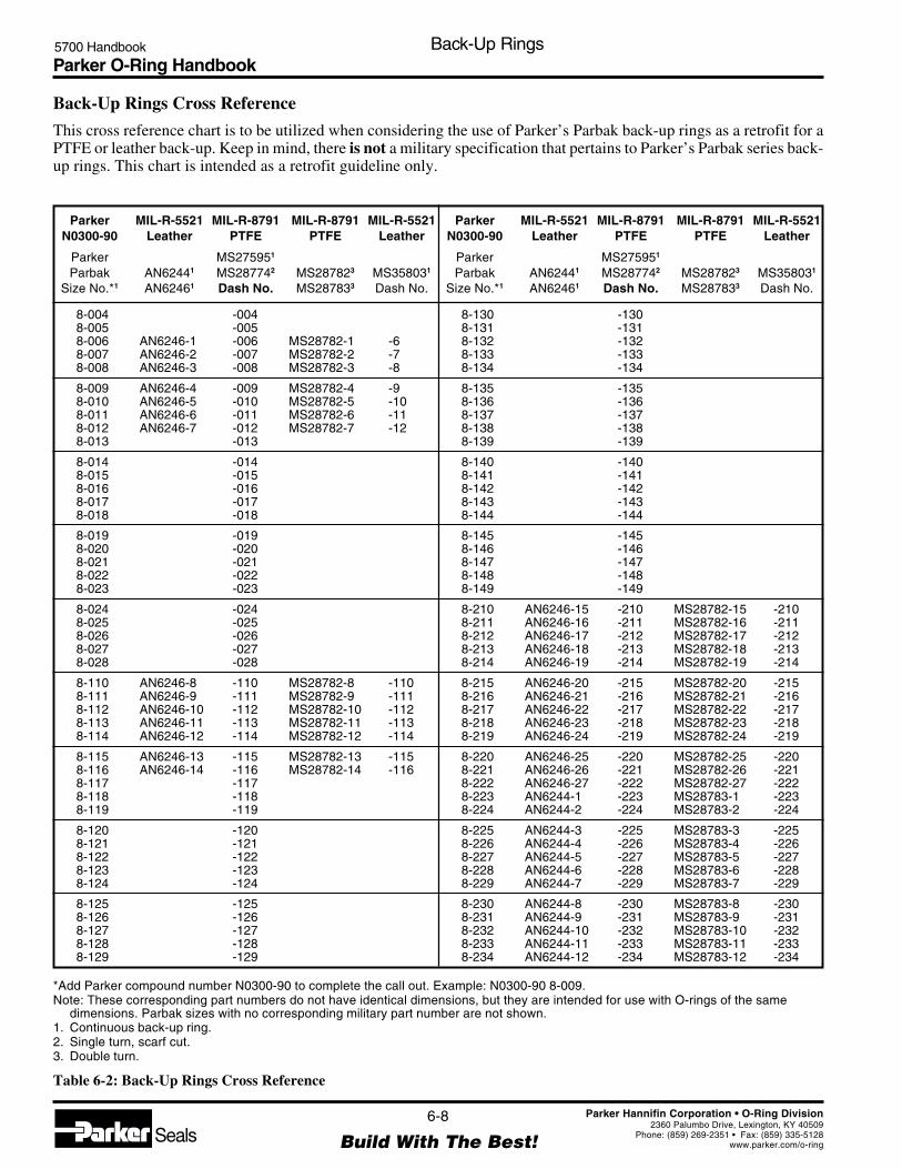
Parker O-Ring Handbook5700 Handbook Back-Up Rings
6-8
Build With The Best!SealsParker Hannifin Corporation • O-Ring Division
2360 Palumbo Drive, Lexington, KY 40509Phone: (859) 269-2351 • Fax: (859) 335-5128
www.parker.com/o-ring
Back-Up Rings Cross Reference
This cross reference chart is to be utilized when considering the use of Parker’s Parbak back-up rings as a retrofit for aPTFE or leather back-up. Keep in mind, there is not a military specification that pertains to Parker’s Parbak series back-up rings. This chart is intended as a retrofit guideline only.
*Add Parker compound number N0300-90 to complete the call out. Example: N0300-90 8-009.Note: These corresponding part numbers do not have identical dimensions, but they are intended for use with O-rings of the same
dimensions. Parbak sizes with no corresponding military part number are not shown.1. Continuous back-up ring.2. Single turn, scarf cut.3. Double turn.
Table 6-2: Back-Up Rings Cross Reference
8-004 -0048-005 -0058-006 AN6246-1 -006 MS28782-1 -68-007 AN6246-2 -007 MS28782-2 -78-008 AN6246-3 -008 MS28782-3 -8
8-009 AN6246-4 -009 MS28782-4 -98-010 AN6246-5 -010 MS28782-5 -108-011 AN6246-6 -011 MS28782-6 -118-012 AN6246-7 -012 MS28782-7 -128-013 -013
8-014 -0148-015 -0158-016 -0168-017 -0178-018 -018
8-019 -0198-020 -0208-021 -0218-022 -0228-023 -023
8-024 -0248-025 -0258-026 -0268-027 -0278-028 -028
8-110 AN6246-8 -110 MS28782-8 -1108-111 AN6246-9 -111 MS28782-9 -1118-112 AN6246-10 -112 MS28782-10 -1128-113 AN6246-11 -113 MS28782-11 -1138-114 AN6246-12 -114 MS28782-12 -114
8-115 AN6246-13 -115 MS28782-13 -1158-116 AN6246-14 -116 MS28782-14 -1168-117 -1178-118 -1188-119 -119
8-120 -1208-121 -1218-122 -1228-123 -1238-124 -124
8-125 -1258-126 -1268-127 -1278-128 -1288-129 -129
Parker MIL-R-5521 MIL-R-8791 MIL-R-8791 MIL-R-5521N0300-90 Leather PTFE PTFE Leather
Parker MS275951
Parbak AN62441 MS287742 MS287823 MS358031
Size No.*1 AN62461 Dash No. MS287833 Dash No.
Parker MIL-R-5521 MIL-R-8791 MIL-R-8791 MIL-R-5521N0300-90 Leather PTFE PTFE Leather
Parker MS275951
Parbak AN62441 MS287742 MS287823 MS358031
Size No.*1 AN62461 Dash No. MS287833 Dash No.
8-130 -1308-131 -1318-132 -1328-133 -1338-134 -134
8-135 -1358-136 -1368-137 -1378-138 -1388-139 -139
8-140 -1408-141 -1418-142 -1428-143 -1438-144 -144
8-145 -1458-146 -1468-147 -1478-148 -1488-149 -149
8-210 AN6246-15 -210 MS28782-15 -2108-211 AN6246-16 -211 MS28782-16 -2118-212 AN6246-17 -212 MS28782-17 -2128-213 AN6246-18 -213 MS28782-18 -2138-214 AN6246-19 -214 MS28782-19 -214
8-215 AN6246-20 -215 MS28782-20 -2158-216 AN6246-21 -216 MS28782-21 -2168-217 AN6246-22 -217 MS28782-22 -2178-218 AN6246-23 -218 MS28782-23 -2188-219 AN6246-24 -219 MS28782-24 -219
8-220 AN6246-25 -220 MS28782-25 -2208-221 AN6246-26 -221 MS28782-26 -2218-222 AN6246-27 -222 MS28782-27 -2228-223 AN6244-1 -223 MS28783-1 -2238-224 AN6244-2 -224 MS28783-2 -224
8-225 AN6244-3 -225 MS28783-3 -2258-226 AN6244-4 -226 MS28783-4 -2268-227 AN6244-5 -227 MS28783-5 -2278-228 AN6244-6 -228 MS28783-6 -2288-229 AN6244-7 -229 MS28783-7 -229
8-230 AN6244-8 -230 MS28783-8 -2308-231 AN6244-9 -231 MS28783-9 -2318-232 AN6244-10 -232 MS28783-10 -2328-233 AN6244-11 -233 MS28783-11 -2338-234 AN6244-12 -234 MS28783-12 -234

Parker O-Ring Handbook5700 Handbook Back-Up Rings
6-9
Build With The Best!SealsParker Hannifin Corporation • O-Ring Division
2360 Palumbo Drive, Lexington, KY 40509Phone: (859) 269-2351 • Fax: (859) 335-5128
www.parker.com/o-ring
Back-Up Rings Cross Reference — Continued
Parker MIL-R-5521 MIL-R-8791 MIL-R-8791 MIL-R-5521N0300-90 Leather PTFE PTFE Leather
Parker MS275951
Parbak AN62441 MS287742 MS287823 MS358031
Size No.*1 AN62461 Dash No. MS287833 Dash No.
Parker MIL-R-5521 MIL-R-8791 MIL-R-8791 MIL-R-5521N0300-90 Leather PTFE PTFE Leather
Parker MS275951
Parbak AN62441 MS287742 MS287823 MS358031
Size No.*1 AN62461 Dash No. MS287833 Dash No.
8-235 AN6244-13 -235 MS28783-13 -2358-236 AN6244-14 -236 MS28783-14 -2368-237 AN6244-15 -237 MS28783-15 -2378-238 AN6244-16 -238 MS28783-16 -2388-239 AN6244-17 -239 MS28783-17 -239
8-240 AN6244-18 -240 MS28783-18 -2408-241 AN6244-19 -241 MS28783-19 -2418-242 AN6244-20 -242 MS28783-20 -2428-243 AN6244-21 -243 MS28783-21 -2438-244 AN6244-22 -244 MS28783-22 -244
8-245 AN6244-23 -245 MS28783-23 -2458-246 AN6244-24 -246 MS28783-24 -2468-247 AN6244-25 -247 MS28783-25 -2478-248 AN6244-268-249 AN6244-27
8-250 AN6244-288-251 AN6244-298-252 AN6244-308-253 AN6244-318-254 AN6244-32
8-255 AN6244-338-256 AN6244-348-257 AN6244-358-258 AN6244-368-259 AN6244-37
8-260 AN6244-388-261 AN6244-398-262 AN6244-408-263 AN6244-418-264 AN6244-42
8-265 AN6244-438-266 AN6244-448-267 AN6244-458-268 AN6244-468-269 AN6244-47
8-270 AN6244-488-271 AN6244-498-272 AN6244-508-273 AN6244-518-274 AN6244-52
8-325 AN6246-28 -325 MS28782-28 -3258-326 AN6246-29 -326 MS28782-29 -3268-327 AN6246-30 -327 MS28782-30 -3278-328 AN6246-31 -328 MS28782-31 -3288-329 AN6246-32 -329 MS28782-32 -329
8-330 AN6246-33 -330 MS28782-33 -3308-331 AN6246-34 -331 MS28782-34 -3318-332 AN6246-35 -332 MS28782-35 -3328-333 AN6246-36 -333 MS28782-36 -3338-334 AN6246-37 -334 MS28782-37 -334
8-335 AN6246-38 -335 MS28782-38 -335
8-336 AN6246-39 -336 MS28782-39 -3368-337 AN6246-40 -337 MS28782-40 -3378-338 AN6246-41 -338 MS28782-41 -3388-339 AN6246-42 -339 MS28782-42 -3398-340 AN6246-43 -340 MS28782-43 -340
8-341 AN6246-44 -341 MS28782-44 -3418-342 AN6246-45 -342 MS28782-45 -3428-343 AN6246-46 -343 MS28782-46 -3438-344 AN6246-47 -344 MS28782-47 -3448-345 AN6246-48 -345 MS28782-48 -345
8-346 AN6246-49 -346 MS28782-49 -3468-347 AN6246-50 -347 MS28782-50 -3478-348 AN6246-51 -348 MS28782-51 -3488-349 AN6246-52 -349 MS28782-52 -3498-425 AN6246-88 -425 MS28782-88 -425
8-426 AN6246-53 -426 MS28782-53 -4268-427 AN6246-54 -427 MS28782-54 -4278-428 AN6246-55 -428 MS28782-55 -4288-429 AN6246-56 -429 MS28782-56 -4298-430 AN6246-57 -430 MS28782-57 -430
8-431 AN6246-58 -431 MS28782-58 -4318-432 AN6246-59 -432 MS28782-59 -4328-433 AN6246-60 -433 MS28782-60 -4338-434 AN6246-61 -434 MS28782-61 -4348-435 AN6246-62 -435 MS28782-62 -435
8-436 AN6246-63 -436 MS28782-63 -4368-437 AN6246-64 -437 MS28782-64 -4378-438 AN6246-65 -438 MS28782-65 -4388-439 AN6246-66 -439 MS28782-66 -4398-440 AN6246-67 -440 MS28782-67 -440
8-441 AN6246-68 -441 MS28782-68 -4418-442 AN6246-69 -442 MS28782-69 -4428-443 AN6246-70 -443 MS28782-70 -4438-444 AN6246-71 -444 MS28782-71 -4448-445 AN6246-72 -445 MS28782-72 -445
8-446 AN6246-73 -446 MS28782-73 -4468-447 AN6246-74 -447 MS28782-74 -4478-448 AN6246-75 -448 MS28782-75 -4488-449 AN6246-76 -449 MS28782-76 -4498-450 AN6246-77 -450 MS28782-77 -450
8-451 AN6246-78 -451 MS28782-78 -4518-452 AN6246-79 -452 MS28782-79 -4528-453 AN6246-80 -453 MS28782-80 -4538-454 AN6246-81 -454 MS28782-81 -4548-455 AN6246-82 -455 MS28782-82 -455
8-456 AN6246-83 -456 MS28782-83 -4568-457 AN6246-84 -457 MS28782-84 -4578-458 AN6246-85 -458 MS28782-85 -4588-459 AN6246-86 -459 MS28782-86 -4598-460 AN6246-87 -460 MS28782-87 -460
*Add Parker compound number N0300-90 to complete the call out. Example: N0300-90 8-009.Note: These corresponding part numbers do not have identical dimensions, but they are intended for use with O-rings of the same
dimensions. Parbak sizes with no corresponding military part number are not shown.1. Continuous back-up ring.2. Single turn, scarf cut.3. Double turn.
Table 6-2: Back-Up Rings Cross Reference (Continued)

Parker O-Ring Handbook5700 Handbook Back-Up Rings
6-10
Build With The Best!SealsParker Hannifin Corporation • O-Ring Division
2360 Palumbo Drive, Lexington, KY 40509Phone: (859) 269-2351 • Fax: (859) 335-5128
www.parker.com/o-ring
Parker Parbaks PTFE Back-Up Rings Leather Back-Up Rings
Continuous ring. Spiral or scarf-cut for most applications. Continuous ring.This discontinuity is often a cause of leaksor damage to the O-ring.
Easiest and quickest to assemble in either Moderately simple to assemble. Scarf or Difficult to assemble over piston. Must bepiston or cylinder groove. spiral cut can be opened, for assembling soaked in oil, stretched, then pounded into
over piston or doubled over itself for place. Less difficult to assemble intoassembly into cylinder groove. cylinder groove.
Good resistance to extrusion. Standard Tends to soften and extrude at temper- Tends to harden and crack at highmaterial satisfactory up to (121°C) 250°F. atures around (149°C) 300°F. temperature.Other compounds available for temper-atures as high as (204°C) 400°F.
Does not cause overly smooth rubbing Deposits on rubbing surface making it Does not cause overly smooth rubbingsurface. Maintains lubrication. extremely smooth. The O-ring then wipes surface. Maintains lubrication.
the surface dry.
Good resistance to radiation. Can be Fair resistance to radiation. No information available.made in compound having even betterresistance when required.
Continuous ring with no loose particles Thin sections of spiral may become lodged Loose leather fibers may become lodgedor sections. under O-ring causing leakage. under O-ring causing leakage.
No scarf cut to open. Coefficient of thermal Low temperature shrinkage may open up Continuous ring.expansion comparable to O-ring material. scarf cut, causing low temperature leakage.
Continuous ring, no scarf cut. High temperature expansion may overlap Continuous ring, no scarf cut.scarf cut causing damage to O-ring.
Absorbs slight amount of oil, aiding Almost completely non-absorbent, will not Tends to absorb moisture, increasinglubrication. hold enough oil to aid lubrication. possibility of corrosion.
Resists cold flow and tendency to extrude Will cold flow and extrude at room Resists cold flow and tendency to extrudeunder high pressure. temperature and high pressure. under high pressure.
Uniform dimensions. Uniform dimensions. Variable dimensions.
Table 6-3: Comparison of Parbak vs. PTFE and Leather Back-Up
Comparison of Parbak vs. PTFE and Leather Back-Up
Parker O-Ring Handbook5700 Handbook Compatibility Tables for Gasses, Fluids, Solids
7-1
Build With The Best!SealsParker Hannifin Corporation • O-Ring Division
2360 Palumbo Drive, Lexington, KY 40509Phone: (859) 269-2351 • Fax: (859) 335-5128
www.parker.com/o-ring
Section VIICompatibility Tables for Gases, Fluids, Solids
Fluid Compatibility Table ............................................................................................................................. 7-2

Parker O-Ring Handbook5700 Handbook Compatibility Tables for Gases, Fluids, Solids
NOTE: *These temperature ranges will apply to the majority of mediafor which the material is potentially recommended. With some mediahowever, the service temperature range may be significantly different.ALWAYS TEST UNDER ACTUAL SERVICE CONDITIONS.
Nitrile (General Service) -34°C to 121°C (-30°F to 250°F)*Nitrile (Low Temperature) -55°C to 107°C (-65°F to 225°F)*Hydrogenated Nitrile -32°C to 149°C (-23°F to 300°F)*Ethylene Propylene -57°C to 121°C (-70°F to 250°F)*Fluorocarbon -26°C to 205°C (-15°F to 400°F)*Hifluor -26°C to 205°C (-15°F to 400°F)*Perfluoroelastomer (Parofluor) -26°C to 260°C (-15°F to 500°F)*
Approximate Service Temperature Ranges for Commonly Used Basic Polymer Types*
COMPOUND COMPATIBILITY RATING1 - Satisfactory2 - Fair (usually OK for static seal)3 - Doubtful (sometimes OK for static seal)4 - Unsatisfactoryx - Insufficient Data
AFLAS -4°C to 232°C (25°F to 450°F)*Neoprene -37°C to 107°C (-35°F to 225°F)*Polyacrylate -21°C to 177°C (- 5°F to 350°F)*Polyurethane -40°C to 82°C (-40°F to 180°F)*Butyl -59°C to 120°C (-75°F to 250°F)*Fluorosilicone -73°C to 177°C (-100°F to 350°F)*Silicone -54°C to 232°C (-65°F to 450°F)*
Nitr
ile N
BR
Hyd
rog
enat
ed N
itrile
HN
BR
Eth
ylen
e P
ropy
len
e E
PD
M
Flu
oro
carb
on
FK
M
Hifl
uo
r F
KM
Per
fluo
roel
asto
mer
FF
KM
Afla
s (T
FE
/Pro
pyle
ne)
FE
PM
Neo
pre
ne/
Ch
loro
pre
ne
CR
Sty
ren
e-B
uta
die
ne
SB
R
Po
lyac
ryla
te A
CM
Po
lyu
reth
ane
AU
, EU
Bu
tyl I
IR
Bu
tad
ien
e B
R
Iso
pre
ne
IR
Nat
ura
l Ru
bb
er N
R
Hyp
alo
n C
SM
Flu
oro
silic
on
e F
VM
Q
Sili
con
e M
Q, V
MQ
, PV
MQ
7-2
Build With The Best!SealsParker Hannifin Corporation • O-Ring Division
2360 Palumbo Drive, Lexington, KY 40509Phone: (859) 269-2351 • Fax: (859) 335-5128
www.parker.com/o-ring
— A —
Abietic Acid V3819-75 X X X X 1 1 X X X X X X X X X X X X
Acetaldehyde E0540-80 3 3 2 4 1 1 3 3 3 4 4 2 2 2 2 3 4 2
Acetamide C0873-70 1 1 1 3 1 1 2 1 4 4 4 2 4 4 4 2 1 2
Acetanilide E0540-80 3 3 1 3 1 1 X 1 1 4 4 1 1 1 1 1 1 2
Acetic Acid, 30% E0540-80 X X 1 X 1 1 X X X X X X X X X X X X
Acetic Acid, 5% E0540-80 2 2 1 1 1 1 1 1 2 4 4 1 2 2 2 1 2 1
Acetic Acid, Glacial E0540-80 2 2 1 2 1 1 3 4 2 4 4 2 2 2 2 3 2 1
Acetic Acid, Hot, High Pressure V8545-75 4 4 3 4 2 1 3 4 4 4 4 4 4 4 4 3 4 3
Acetic Anhydride C0873-70 3 4 2 4 1 1 2 2 2 4 4 2 2 2 2 2 4 2
Acetoacetic Acid E0540-80 3 3 1 3 1 1 X 1 1 4 4 1 1 1 1 1 1 2
Acetone E0540-80 4 4 1 4 2 1 2 4 4 4 4 1 4 4 4 3 4 4
Acetone Cyanohydrin E0540-80 3 3 1 3 1 1 X 1 1 4 4 1 1 1 1 1 1 2
Acetonitrile E0540-80 3 X 1 1 1 1 1 X X X X X X X X X X X
Acetophenetidine V1164-75 2 2 4 1 1 1 X 4 4 4 3 4 4 4 4 4 2 X
Acetophenone E0540-80 4 4 1 4 2 1 2 4 4 4 4 2 4 4 4 4 4 4
Acetotoluidide V1164-75 2 2 4 1 1 1 X 4 4 4 3 4 4 4 4 4 2 X
Acetyl Acetone E0540-80 4 4 1 4 2 1 2 4 4 4 4 1 4 4 4 4 4 4
Acetyl Bromide V1164-75 4 4 1 1 1 1 2 4 4 4 4 1 4 4 4 4 4 4
Acetyl Chloride V1164-75 4 4 4 1 1 1 2 4 4 4 4 4 4 4 4 4 1 4
Acetylene E0540-80 1 1 1 1 1 1 1 2 2 4 4 1 2 2 2 2 X 2
Acetylene Tetrabromide V1164-75 4 4 1 1 1 1 1 2 4 X 4 1 X X X X X X
Acetylene Tetrachloride V1164-75 4 4 1 1 1 1 1 2 4 X 4 1 X X X X X X
Acetylsalicylic Acid V1164-75 2 2 4 1 1 1 X 4 4 4 3 4 4 4 4 4 2 X
Acids, Non-organic V3819-75 X X X X 1 1 X X X X X X X X X X X X
Acids, Organic V3819-75 X X X X 1 1 X X X X X X X X X X X X
Aconitic Acid V3819-75 X X X X 1 1 X X X X X X X X X X X X
Acridine V3819-75 X X X X 1 1 X X X X X X X X X X X X
Acrolein E0540-80 3 3 1 3 1 1 X 1 1 4 4 1 1 1 1 1 1 2
Acrylic Acid V1164-75 2 2 4 1 1 1 X 4 4 4 3 4 4 4 4 4 2 X
Acrylonitrile V8545-75 4 4 4 3 1 1 3 4 3 4 4 4 X 3 3 3 4 4
Adipic Acid E0540-80 1 1 2 X 1 1 2 X X X X X X X X X X X
Aero Lubriplate N0674-70 1 1 4 1 1 1 2 1 2 1 1 4 4 4 4 1 1 2
Aero Shell 17 Grease N0674-70 1 1 4 1 1 1 2 2 4 1 1 4 4 4 4 1 1 2
Aero Shell 750 V1164-75 2 2 4 1 1 1 2 4 4 2 4 4 4 4 4 4 2 4
Aero Shell 7A Grease N0674-70 2 2 4 1 1 1 2 2 4 1 1 4 4 4 4 1 1 2
Aero Shell IAC N0674-70 1 1 4 1 1 1 2 2 4 1 1 4 4 4 4 1 1 2
Aerosafe 2300 E0540-80 4 4 1 4 1 1 2 4 4 4 4 2 4 4 4 4 3 3
Aerosafe 2300W E0540-80 4 4 1 4 1 1 2 4 4 4 4 2 4 4 4 4 3 3
Aerozene 50 (50% Hydrazine 50% UDMH) E0540-80 3 3 1 4 3 2 2 4 4 X 4 1 4 4 4 4 4 4
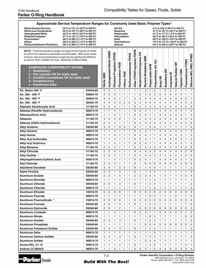
Parker O-Ring Handbook5700 Handbook Compatibility Tables for Gases, Fluids, Solids
NOTE: *These temperature ranges will apply to the majority of mediafor which the material is potentially recommended. With some mediahowever, the service temperature range may be significantly different.ALWAYS TEST UNDER ACTUAL SERVICE CONDITIONS.
Nitrile (General Service) -34°C to 121°C (-30°F to 250°F)*Nitrile (Low Temperature) -55°C to 107°C (-65°F to 225°F)*Hydrogenated Nitrile -32°C to 149°C (-23°F to 300°F)*Ethylene Propylene -57°C to 121°C (-70°F to 250°F)*Fluorocarbon -26°C to 205°C (-15°F to 400°F)*Hifluor -26°C to 205°C (-15°F to 400°F)*Perfluoroelastomer (Parofluor) -26°C to 260°C (-15°F to 500°F)*
Approximate Service Temperature Ranges for Commonly Used Basic Polymer Types*
COMPOUND COMPATIBILITY RATING1 - Satisfactory2 - Fair (usually OK for static seal)3 - Doubtful (sometimes OK for static seal)4 - Unsatisfactoryx - Insufficient Data
AFLAS -4°C to 232°C (25°F to 450°F)*Neoprene -37°C to 107°C (-35°F to 225°F)*Polyacrylate -21°C to 177°C (- 5°F to 350°F)*Polyurethane -40°C to 82°C (-40°F to 180°F)*Butyl -59°C to 120°C (-75°F to 250°F)*Fluorosilicone -73°C to 177°C (-100°F to 350°F)*Silicone -54°C to 232°C (-65°F to 450°F)*
Nitr
ile N
BR
Hyd
rog
enat
ed N
itrile
HN
BR
Eth
ylen
e P
ropy
len
e E
PD
M
Flu
oro
carb
on
FK
M
Hifl
uo
r F
KM
Per
fluo
roel
asto
mer
FF
KM
Afla
s (T
FE
/Pro
pyle
ne)
FE
PM
Neo
pre
ne/
Ch
loro
pre
ne
CR
Sty
ren
e-B
uta
die
ne
SB
R
Po
lyac
ryla
te A
CM
Po
lyu
reth
ane
AU
, EU
Bu
tyl I
IR
Bu
tad
ien
e B
R
Iso
pre
ne
IR
Nat
ura
l Ru
bb
er N
R
Hyp
alo
n C
SM
Flu
oro
silic
on
e F
VM
Q
Sili
con
e M
Q, V
MQ
, PV
MQ
7-3
Build With The Best!SealsParker Hannifin Corporation • O-Ring Division
2360 Palumbo Drive, Lexington, KY 40509Phone: (859) 269-2351 • Fax: (859) 335-5128
www.parker.com/o-ring
Air, Below 200° F E0540-80 2 2 1 1 1 1 1 1 2 1 2 1 2 2 2 1 1 1
Air, 200 - 300° F S0604-70 3 3 2 1 1 1 1 2 4 2 3 2 4 4 4 2 1 1
Air, 300 - 400° F S0604-70 4 4 4 1 1 1 2 4 4 4 4 4 4 4 4 4 2 1
Air, 400 - 500° F S0455-70 4 4 4 3 2 2 3 4 4 4 4 4 4 4 4 4 4 2
Aliphatic Dicarboxylic Acid V1164-75 2 2 4 1 1 1 X 4 4 4 3 4 4 4 4 4 2 X
Alkanes (Paraffin Hydrocarbons) N0674-70 1 1 4 1 1 1 X 2 4 1 1 4 4 4 4 2 1 2
Alkanesulfonic Acid N0674-70 1 1 4 1 1 1 X 2 4 1 1 4 4 4 4 2 1 2
Alkazene V1164-75 4 4 4 2 1 1 2 4 4 4 4 4 4 4 4 4 2 4
Alkenes (Olefin Hydrocarbons) V1164-75 2 2 4 1 1 1 X 4 4 4 3 4 4 4 4 4 2 X
Alkyl Acetone E0540-80 3 3 1 3 2 1 X 1 1 4 4 1 1 1 1 1 1 2
Alkyl Alcohol N0674-70 1 1 4 1 1 1 X 2 4 1 1 4 4 4 4 2 1 2
Alkyl Amine N0674-70 1 1 4 1 1 1 X 2 4 1 1 4 4 4 4 2 1 2
Alkyl Aryl Sulfonates N0674-70 1 1 4 1 1 1 X 2 4 1 1 4 4 4 4 2 1 2
Alkyl Aryl Sulfonics N0674-70 1 1 4 1 1 1 X 2 4 1 1 4 4 4 4 2 1 2
Alkyl Benzene V1164-75 2 2 4 1 1 1 X 4 4 4 3 4 4 4 4 4 2 X
Alkyl Chloride V1164-75 2 2 4 1 1 1 X 4 4 4 3 4 4 4 4 4 2 X
Alkyl Sulfide * V1164-75 2 2 4 1 1 1 X 4 4 4 3 4 4 4 4 4 2 X
Alkylnaphthalene Sulfonic Acid N0674-70 1 1 4 1 1 1 X 2 4 1 1 4 4 4 4 2 1 2
Allyl Chloride V1164-75 2 2 4 1 1 1 X 1 X X X X X X X X X X
Allylidene Diacetate E0540-80 3 3 1 3 2 1 X 1 1 4 4 1 1 1 1 1 1 2
Alpha Picoline E0540-80 3 3 1 3 1 1 X 1 1 4 4 1 1 1 1 1 1 2
Aluminum Acetate E0540-80 2 2 1 4 1 1 2 2 2 4 4 1 4 1 1 4 4 4
Aluminum Bromide N0674-70 1 1 1 1 1 1 1 1 1 1 3 1 1 1 1 1 1 1
Aluminum Chlorate E0540-80 3 3 1 3 1 1 X 1 1 4 4 1 1 1 1 1 1 2
Aluminum Chloride N0674-70 1 1 1 1 1 1 1 1 1 1 3 1 1 1 1 1 1 2
Aluminum Ethylate V3819-75 X X X X 1 1 X X X X X X X X X X X X
Aluminum Fluoride N0674-70 1 1 1 1 1 1 1 1 1 X 3 1 1 1 2 1 1 2
Aluminum Fluorosilicate * V3819-75 X X X X 1 1 X X X X X X X X X X X X
Aluminum Formate E0540-80 3 3 1 3 1 1 X 1 1 4 4 1 1 1 1 1 1 2
Aluminum Hydroxide E0540-80 2 X 1 2 1 1 1 X X X X X X X X X X 2
Aluminum Linoleate N0674-70 1 1 4 1 1 1 X 2 4 1 1 4 4 4 4 2 1 2
Aluminum Nitrate N0674-70 1 1 1 1 1 1 1 1 1 X 3 1 1 1 1 1 X 2
Aluminum Oxalate E0540-80 3 3 1 3 1 1 X 1 1 4 4 1 1 1 1 1 1 2
Aluminum Phosphate E0540-80 1 1 1 1 1 1 1 1 X X X X X X X X X 2
Aluminum Potassium Sulfate E0540-80 3 3 1 3 1 1 X 1 1 4 4 1 1 1 1 1 1 2
Aluminum Salts N0674-70 1 1 1 1 1 1 1 1 1 1 3 1 1 1 1 1 1 1
Aluminum Sodium Sulfate E0540-80 3 3 1 3 1 1 X 1 1 4 4 1 1 1 1 1 1 2
Aluminum Sulfate N0674-70 1 1 1 1 1 1 1 1 2 4 4 1 1 1 1 1 1 1
Alums-NH3 -Cr -K N0674-70 1 1 1 4 1 1 2 1 1 4 X 1 1 1 1 1 4 1
Ambrex 33 (Mobil) N0674-70 1 1 4 1 1 1 2 2 4 1 2 4 4 4 4 3 3 4

Parker O-Ring Handbook5700 Handbook Compatibility Tables for Gases, Fluids, Solids
NOTE: *These temperature ranges will apply to the majority of mediafor which the material is potentially recommended. With some mediahowever, the service temperature range may be significantly different.ALWAYS TEST UNDER ACTUAL SERVICE CONDITIONS.
Nitrile (General Service) -34°C to 121°C (-30°F to 250°F)*Nitrile (Low Temperature) -55°C to 107°C (-65°F to 225°F)*Hydrogenated Nitrile -32°C to 149°C (-23°F to 300°F)*Ethylene Propylene -57°C to 121°C (-70°F to 250°F)*Fluorocarbon -26°C to 205°C (-15°F to 400°F)*Hifluor -26°C to 205°C (-15°F to 400°F)*Perfluoroelastomer (Parofluor) -26°C to 260°C (-15°F to 500°F)*
Approximate Service Temperature Ranges for Commonly Used Basic Polymer Types*
COMPOUND COMPATIBILITY RATING1 - Satisfactory2 - Fair (usually OK for static seal)3 - Doubtful (sometimes OK for static seal)4 - Unsatisfactoryx - Insufficient Data
AFLAS -4°C to 232°C (25°F to 450°F)*Neoprene -37°C to 107°C (-35°F to 225°F)*Polyacrylate -21°C to 177°C (- 5°F to 350°F)*Polyurethane -40°C to 82°C (-40°F to 180°F)*Butyl -59°C to 120°C (-75°F to 250°F)*Fluorosilicone -73°C to 177°C (-100°F to 350°F)*Silicone -54°C to 232°C (-65°F to 450°F)*
Nitr
ile N
BR
Hyd
rog
enat
ed N
itrile
HN
BR
Eth
ylen
e P
ropy
len
e E
PD
M
Flu
oro
carb
on
FK
M
Hifl
uo
r F
KM
Per
fluo
roel
asto
mer
FF
KM
Afla
s (T
FE
/Pro
pyle
ne)
FE
PM
Neo
pre
ne/
Ch
loro
pre
ne
CR
Sty
ren
e-B
uta
die
ne
SB
R
Po
lyac
ryla
te A
CM
Po
lyu
reth
ane
AU
, EU
Bu
tyl I
IR
Bu
tad
ien
e B
R
Iso
pre
ne
IR
Nat
ura
l Ru
bb
er N
R
Hyp
alo
n C
SM
Flu
oro
silic
on
e F
VM
Q
Sili
con
e M
Q, V
MQ
, PV
MQ
7-4
Build With The Best!SealsParker Hannifin Corporation • O-Ring Division
2360 Palumbo Drive, Lexington, KY 40509Phone: (859) 269-2351 • Fax: (859) 335-5128
www.parker.com/o-ring
Ambrex 830 (Mobil) N0674-70 1 1 3 1 1 1 2 2 4 1 1 3 4 4 4 2 1 2
Amines-Mixed C0873-70 4 4 2 4 3 2 3 2 2 4 4 2 2 2 2 4 4 2
Aminoanthraquinone V3819-75 X X X X 1 1 X X X X X X X X X X X X
Aminoazobenzene V3819-75 X X X X 1 1 X X X X X X X X X X X X
Aminobenzene Sulfonic Acid V3819-75 X X X X 1 1 X X X X X X X X X X X X
Aminobenzoic Acid V3819-75 X X X X 1 1 X X X X X X X X X X X X
Aminopyridine V3819-75 X X X X 1 1 X X X X X X X X X X X X
Aminosalicylic Acid V3819-75 X X X X 1 1 X X X X X X X X X X X X
Ammonia (Anhydrous) C0873-70 2 2 1 4 3 2 2 1 4 4 4 1 4 4 4 4 4 2
Ammonia and Lithium Metal in Solution E0540-80 2 2 2 4 4 4 3 X 4 4 4 2 4 4 4 4 4 4
Ammonia, Gas, Cold C0873-70 1 1 1 4 2 1 2 1 1 4 X 1 1 1 1 1 4 1
Ammonia, Gas, Hot C0873-70 4 4 2 4 3 2 2 2 4 4 X 2 4 4 4 2 4 X
Ammonia, Liquid (Anhydrous) C0873-70 2 2 1 4 3 2 2 1 4 4 4 1 4 4 4 2 4 2
Ammonium Acetate E0540-80 3 3 1 3 2 1 X 1 1 4 4 1 1 1 1 1 1 2
Ammonium Arsenate E0540-80 3 3 1 3 1 1 X 1 1 4 4 1 1 1 1 1 1 2
Ammonium Benzoate E0540-80 3 3 1 3 1 1 X 1 1 4 4 1 1 1 1 1 1 2
Ammonium Bicarbonate E0540-80 3 3 1 3 1 1 X 1 1 4 4 1 1 1 1 1 1 2
Ammonium Bisulfite E0540-80 3 3 1 3 1 1 X 1 1 4 4 1 1 1 1 1 1 2
Ammonium Bromide N0674-70 1 1 1 1 1 1 1 1 1 X 1 1 X X 1 1 X X
Ammonium Carbamate E0540-80 3 3 1 3 1 1 X 1 1 4 4 1 1 1 1 1 1 2
Ammonium Carbonate C0873-70 4 4 1 1 1 1 1 1 1 4 4 1 X X 1 1 X X
Ammonium Chloride, 2N N0674-70 1 1 1 1 1 1 1 1 1 X 1 1 X X 1 1 X X
Ammonium Citrate E0540-80 3 3 1 3 1 1 X 1 1 4 4 1 1 1 1 1 1 2
Ammonium Dichromate E0540-80 3 3 1 3 1 1 X 1 1 4 4 1 1 1 1 1 1 2
Ammonium Diphosphate E0540-80 3 3 1 3 1 1 X 1 1 4 4 1 1 1 1 1 1 2
Ammonium Fluoride N0674-70 1 1 1 1 1 1 1 1 1 X 1 1 X X 1 1 X X
Ammonium Fluorosilicate * V3819-75 X X X X 1 1 X X X X X X X X X X X X
Ammonium Formate E0540-80 3 3 1 3 1 1 X 1 1 4 4 1 1 1 1 1 1 2
Ammonium Hydroxide, 3 Molar E0540-80 1 1 1 3 2 2 2 1 2 4 4 1 2 2 2 1 1 1
Ammonium Hydroxide, Concentrated E0540-80 4 4 1 4 3 2 2 1 3 4 4 1 3 3 3 1 1 1
Ammonium Iodide N0674-70 1 1 1 1 1 1 1 1 1 X 1 1 X X 1 1 X X
Ammonium Lactate E0540-80 3 3 1 3 1 1 X 1 1 4 4 1 1 1 1 1 1 2
Ammonium Metaphosphate E0540-80 3 3 1 3 1 1 X 1 1 4 4 1 1 1 1 1 1 2
Ammonium Molybdenate * E0540-80 3 3 1 3 1 1 X 1 1 4 4 1 1 1 1 1 1 2
Ammonium Nitrate, 2N N0674-70 1 1 1 X X X 2 1 1 2 X 1 X X 3 1 X X
Ammonium Nitrite N0674-70 1 1 1 X 1 1 2 1 1 X X 1 1 1 1 1 X 2
Ammonium Oxalate E0540-80 3 3 1 3 1 1 X 1 1 4 4 1 1 1 1 1 1 2
Ammonium Perchlorate E0540-80 3 3 1 3 1 1 X 1 1 4 4 1 1 1 1 1 1 2
Ammonium Perchloride V3819-75 X X X X 1 1 X X X X X X X X X X X X
Ammonium Persulfate 10% E0540-80 4 4 1 X X X 2 1 4 4 4 1 X 1 1 X X X

Parker O-Ring Handbook5700 Handbook Compatibility Tables for Gases, Fluids, Solids
NOTE: *These temperature ranges will apply to the majority of mediafor which the material is potentially recommended. With some mediahowever, the service temperature range may be significantly different.ALWAYS TEST UNDER ACTUAL SERVICE CONDITIONS.
Nitrile (General Service) -34°C to 121°C (-30°F to 250°F)*Nitrile (Low Temperature) -55°C to 107°C (-65°F to 225°F)*Hydrogenated Nitrile -32°C to 149°C (-23°F to 300°F)*Ethylene Propylene -57°C to 121°C (-70°F to 250°F)*Fluorocarbon -26°C to 205°C (-15°F to 400°F)*Hifluor -26°C to 205°C (-15°F to 400°F)*Perfluoroelastomer (Parofluor) -26°C to 260°C (-15°F to 500°F)*
Approximate Service Temperature Ranges for Commonly Used Basic Polymer Types*
COMPOUND COMPATIBILITY RATING1 - Satisfactory2 - Fair (usually OK for static seal)3 - Doubtful (sometimes OK for static seal)4 - Unsatisfactoryx - Insufficient Data
AFLAS -4°C to 232°C (25°F to 450°F)*Neoprene -37°C to 107°C (-35°F to 225°F)*Polyacrylate -21°C to 177°C (- 5°F to 350°F)*Polyurethane -40°C to 82°C (-40°F to 180°F)*Butyl -59°C to 120°C (-75°F to 250°F)*Fluorosilicone -73°C to 177°C (-100°F to 350°F)*Silicone -54°C to 232°C (-65°F to 450°F)*
Nitr
ile N
BR
Hyd
rog
enat
ed N
itrile
HN
BR
Eth
ylen
e P
ropy
len
e E
PD
M
Flu
oro
carb
on
FK
M
Hifl
uo
r F
KM
Per
fluo
roel
asto
mer
FF
KM
Afla
s (T
FE
/Pro
pyle
ne)
FE
PM
Neo
pre
ne/
Ch
loro
pre
ne
CR
Sty
ren
e-B
uta
die
ne
SB
R
Po
lyac
ryla
te A
CM
Po
lyu
reth
ane
AU
, EU
Bu
tyl I
IR
Bu
tad
ien
e B
R
Iso
pre
ne
IR
Nat
ura
l Ru
bb
er N
R
Hyp
alo
n C
SM
Flu
oro
silic
on
e F
VM
Q
Sili
con
e M
Q, V
MQ
, PV
MQ
7-5
Build With The Best!SealsParker Hannifin Corporation • O-Ring Division
2360 Palumbo Drive, Lexington, KY 40509Phone: (859) 269-2351 • Fax: (859) 335-5128
www.parker.com/o-ring
Ammonium Persulfate Solution E0540-80 4 4 1 X 1 1 2 X 4 4 4 1 X 1 1 X X X
Ammonium Phosphate N0674-70 1 1 1 4 1 1 2 1 1 X X 1 X 1 1 1 X 1
Ammonium Phosphate, Dibasic N0674-70 1 1 1 X 1 1 2 1 1 X X 1 X 1 1 1 X 1
Ammonium Phosphate, Mono-Basic N0674-70 1 1 1 X 1 1 2 1 1 X X 1 X 1 1 1 X 1
Ammonium Phosphate, Tribasic N0674-70 1 1 1 X 1 1 2 1 1 X X 1 X 1 1 1 X 1
Ammonium Phosphite E0540-80 3 3 1 3 1 1 X 1 1 4 4 1 1 1 1 1 1 2
Ammonium Picrate E0540-80 3 3 1 3 1 1 X 1 1 4 4 1 1 1 1 1 1 2
Ammonium Polysulfide E0540-80 3 3 1 3 1 1 X 1 1 4 4 1 1 1 1 1 1 2
Ammonium Salicylate E0540-80 3 3 1 3 1 1 X 1 1 4 4 1 1 1 1 1 1 2
Ammonium Salts N0674-70 1 1 1 3 1 1 2 1 1 3 X 1 X 1 1 1 3 1
Ammonium Sulfamate E0540-80 3 3 1 3 1 1 X 1 1 4 4 1 1 1 1 1 1 2
Ammonium Sulfate N0674-70 1 1 1 4 1 1 2 1 2 4 X 1 1 1 1 1 X X
Ammonium Sulfate Nitrate N0674-70 1 1 1 4 1 1 2 1 2 4 X 1 1 1 1 1 X X
Ammonium Sulfide N0674-70 1 1 1 4 1 1 2 1 2 4 X 1 1 1 1 1 X X
Ammonium Sulfite E0540-80 3 3 1 3 1 1 X 1 1 4 4 1 1 1 1 1 1 2
Ammonium Thiocyanate E0540-80 3 3 1 3 1 1 X 1 1 4 4 1 1 1 1 1 1 2
Ammonium Thioglycolate E0540-80 3 3 1 3 1 1 X 1 1 4 4 1 1 1 1 1 1 2
Ammonium Thiosulfate E0540-80 3 3 1 3 1 1 X 1 1 4 4 1 1 1 1 1 1 2
Ammonium Tungstate E0540-80 3 3 1 3 1 1 X 1 1 4 4 1 1 1 1 1 1 2
Ammonium Valerate E0540-80 3 3 1 3 1 1 X 1 1 4 4 1 1 1 1 1 1 2
Amyl Acetate N0674-70 1 1 3 4 1 1 3 4 4 4 4 3 4 4 4 4 4 4
Amyl Alcohol E0540-80 2 2 1 2 1 1 1 2 2 4 4 1 2 2 2 2 1 4
Amyl Borate N0674-70 1 1 4 1 1 1 2 1 4 X X 4 4 4 4 1 X X
Amyl Butyrate N0674-70 1 1 4 1 1 1 X 2 4 1 1 4 4 4 4 2 1 2
Amyl Chloride V1164-75 X X 4 1 1 1 2 4 4 4 X 4 4 4 4 4 2 4
Amyl Chloronaphthalene V1164-75 4 4 4 1 1 1 2 4 4 4 X 4 4 4 4 4 2 4
Amyl Cinnamic Aldehyde V1164-75 2 2 4 1 1 1 X 4 4 4 3 4 4 4 4 4 2 X
Amyl Laurate V1164-75 2 2 4 1 1 1 X 4 4 4 3 4 4 4 4 4 2 X
Amyl Mercaptan V1164-75 2 2 4 1 1 1 X 4 4 4 3 4 4 4 4 4 2 X
Amyl Naphthalene V1164-75 4 4 4 1 1 1 2 4 4 2 4 4 4 4 4 4 1 4
Amyl Nitrate E0540-80 3 3 1 3 1 1 X 1 1 4 4 1 1 1 1 1 1 2
Amyl Nitrite E0540-80 3 3 1 3 1 1 X 1 1 4 4 1 1 1 1 1 1 2
Amyl Phenol V3819-75 X X X X 1 1 X X X X X X X X X X X X
Amyl Propionate N0674-70 1 1 4 1 2 1 X 2 4 1 1 4 4 4 4 2 1 2
Anderol, L- 826 (di-ester) V1164-75 2 2 4 1 1 1 2 4 4 2 4 4 4 4 4 4 2 4
Anderol, L- 829 (di-ester) V1164-75 2 2 4 1 1 1 2 4 4 2 4 4 4 4 4 4 2 4
Anderol, L-774 (di-ester) V1164-75 2 2 4 1 1 1 2 4 4 2 4 4 4 4 4 4 2 4
ANG-25 (Di-ester Base) (TG749) V1164-75 2 2 4 1 1 1 2 4 4 2 4 4 4 4 4 4 2 2
ANG-25 (Glyceral Ester) E0540-80 2 2 1 1 1 1 1 2 2 4 4 2 2 2 2 2 2 2
Aniline E0540-80 4 4 2 3 1 1 2 4 4 4 4 2 4 4 4 4 3 4
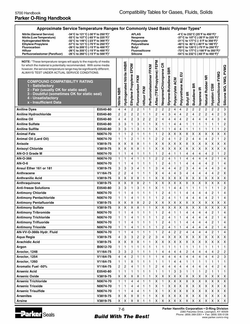
Parker O-Ring Handbook5700 Handbook Compatibility Tables for Gases, Fluids, Solids
NOTE: *These temperature ranges will apply to the majority of mediafor which the material is potentially recommended. With some mediahowever, the service temperature range may be significantly different.ALWAYS TEST UNDER ACTUAL SERVICE CONDITIONS.
Nitrile (General Service) -34°C to 121°C (-30°F to 250°F)*Nitrile (Low Temperature) -55°C to 107°C (-65°F to 225°F)*Hydrogenated Nitrile -32°C to 149°C (-23°F to 300°F)*Ethylene Propylene -57°C to 121°C (-70°F to 250°F)*Fluorocarbon -26°C to 205°C (-15°F to 400°F)*Hifluor -26°C to 205°C (-15°F to 400°F)*Perfluoroelastomer (Parofluor) -26°C to 260°C (-15°F to 500°F)*
Approximate Service Temperature Ranges for Commonly Used Basic Polymer Types*
COMPOUND COMPATIBILITY RATING1 - Satisfactory2 - Fair (usually OK for static seal)3 - Doubtful (sometimes OK for static seal)4 - Unsatisfactoryx - Insufficient Data
AFLAS -4°C to 232°C (25°F to 450°F)*Neoprene -37°C to 107°C (-35°F to 225°F)*Polyacrylate -21°C to 177°C (- 5°F to 350°F)*Polyurethane -40°C to 82°C (-40°F to 180°F)*Butyl -59°C to 120°C (-75°F to 250°F)*Fluorosilicone -73°C to 177°C (-100°F to 350°F)*Silicone -54°C to 232°C (-65°F to 450°F)*
Nitr
ile N
BR
Hyd
rog
enat
ed N
itrile
HN
BR
Eth
ylen
e P
ropy
len
e E
PD
M
Flu
oro
carb
on
FK
M
Hifl
uo
r F
KM
Per
fluo
roel
asto
mer
FF
KM
Afla
s (T
FE
/Pro
pyle
ne)
FE
PM
Neo
pre
ne/
Ch
loro
pre
ne
CR
Sty
ren
e-B
uta
die
ne
SB
R
Po
lyac
ryla
te A
CM
Po
lyu
reth
ane
AU
, EU
Bu
tyl I
IR
Bu
tad
ien
e B
R
Iso
pre
ne
IR
Nat
ura
l Ru
bb
er N
R
Hyp
alo
n C
SM
Flu
oro
silic
on
e F
VM
Q
Sili
con
e M
Q, V
MQ
, PV
MQ
7-6
Build With The Best!SealsParker Hannifin Corporation • O-Ring Division
2360 Palumbo Drive, Lexington, KY 40509Phone: (859) 269-2351 • Fax: (859) 335-5128
www.parker.com/o-ring
Aniline Dyes E0540-80 4 4 2 2 1 1 2 2 2 4 4 2 2 2 2 2 2 3
Aniline Hydrochloride E0540-80 2 2 2 2 1 1 2 4 3 4 4 2 4 2 2 4 2 3
Aniline Oil E0540-80 4 4 2 3 2 2 2 4 4 4 4 2 4 4 4 4 3 4
Aniline Sulfate E0540-80 3 3 1 3 1 1 X 1 1 4 4 1 1 1 1 1 1 2
Aniline Sulfite E0540-80 3 3 1 3 1 1 X 1 1 4 4 1 1 1 1 1 1 2
Animal Fats N0674-70 1 1 2 1 1 1 1 2 X X X X X X X X X X
Animal Oil (Lard Oil) N0674-70 1 1 2 1 1 1 2 2 4 1 2 2 4 4 4 2 1 2
Anisole V3819-75 X X X X 1 1 X X X X X X X X X X X X
Anisoyl Chloride V3819-75 X X X X 1 1 X X X X X X X X X X X X
AN-O-3 Grade M N0674-70 1 1 4 1 1 1 1 2 4 1 1 4 4 4 4 2 1 2
AN-O-366 N0674-70 1 1 4 1 1 1 2 2 4 1 1 4 4 4 4 2 1 4
AN-O-6 N0674-70 1 1 4 1 1 1 1 2 4 1 1 4 4 4 4 2 1 4
Ansul Ether 161 or 181 V3819-75 3 3 3 4 1 1 3 4 4 4 2 3 4 4 4 4 3 4
Anthracene V1164-75 2 2 4 1 1 1 X 4 4 4 3 4 4 4 4 4 2 X
Anthranilic Acid V3819-75 X X X X 1 1 X X X X X X X X X X X X
Anthraquinone V3819-75 X X X X 2 1 X X X X X X X X X X X X
Anti-freeze Solutions E0540-80 3 3 1 3 1 1 X 1 1 4 4 1 1 1 1 1 1 2
Antimony Chloride N0674-70 1 1 4 1 1 1 1 2 4 1 1 4 4 4 4 2 1 4
Antimony Pentachloride N0674-70 1 1 4 1 1 1 1 2 4 1 1 4 4 4 4 2 1 4
Antimony Pentafluoride V3819-75 X X X X 2 2 X X X X X X X X X X X X
Antimony Sulfate V3819-75 X X X X 1 1 X X X X X X X X X X X X
Antimony Tribromide N0674-70 1 1 4 1 1 1 1 2 4 1 1 4 4 4 4 2 1 4
Antimony Trichloride N0674-70 1 1 4 1 1 1 1 2 4 1 1 4 4 4 4 2 1 4
Antimony Trifluoride N0674-70 1 1 4 1 1 1 1 2 4 1 1 4 4 4 4 2 1 4
Antimony Trioxide N0674-70 1 1 4 1 1 1 1 2 4 1 1 4 4 4 4 2 1 4
AN-VV-O-366b Hydr. Fluid N0674-70 1 1 4 1 1 1 1 2 4 2 2 4 4 4 4 2 1 4
Aqua Regia V3819-75 4 3 3 2 2 2 3 4 X X X X X X X X X X
Arachidic Acid V3819-75 X X X X 1 1 X X X X X X X X X X X X
Argon B0612-70 1 1 1 1 1 1 1 1 1 1 1 1 1 1 1 1 1 1
Aroclor, 1248 V1164-75 3 3 2 1 1 1 1 4 4 4 4 2 4 4 4 4 2 2
Aroclor, 1254 V1164-75 4 4 2 1 1 1 1 4 4 4 4 4 4 4 4 4 2 3
Aroclor, 1260 V1164-75 1 1 X 1 1 1 1 1 1 4 4 1 1 1 1 1 1 1
Aromatic Fuel -50% V1164-75 2 2 4 1 1 1 2 4 4 4 4 4 4 4 4 4 2 4
Arsenic Acid E0540-80 1 1 1 1 1 1 1 1 1 3 3 1 1 1 2 1 1 1
Arsenic Oxide V3819-75 X X X X 1 1 X X X X X X X X X X X X
Arsenic Trichloride N0674-70 1 1 4 4 1 1 X 1 X X X X X X X X X X
Arsenic Trioxide N0674-70 1 1 4 4 1 1 X 1 X X X X X X X X X X
Arsenic Trisulfide N0674-70 1 1 4 4 1 1 X 1 X X X X X X X X X X
Arsenites V3819-75 X X X X 1 1 X X X X X X X X X X X X
Arsine V3819-75 X X X X 1 1 X X X X X X X X X X X X

Parker O-Ring Handbook5700 Handbook Compatibility Tables for Gases, Fluids, Solids
NOTE: *These temperature ranges will apply to the majority of mediafor which the material is potentially recommended. With some mediahowever, the service temperature range may be significantly different.ALWAYS TEST UNDER ACTUAL SERVICE CONDITIONS.
Nitrile (General Service) -34°C to 121°C (-30°F to 250°F)*Nitrile (Low Temperature) -55°C to 107°C (-65°F to 225°F)*Hydrogenated Nitrile -32°C to 149°C (-23°F to 300°F)*Ethylene Propylene -57°C to 121°C (-70°F to 250°F)*Fluorocarbon -26°C to 205°C (-15°F to 400°F)*Hifluor -26°C to 205°C (-15°F to 400°F)*Perfluoroelastomer (Parofluor) -26°C to 260°C (-15°F to 500°F)*
Approximate Service Temperature Ranges for Commonly Used Basic Polymer Types*
COMPOUND COMPATIBILITY RATING1 - Satisfactory2 - Fair (usually OK for static seal)3 - Doubtful (sometimes OK for static seal)4 - Unsatisfactoryx - Insufficient Data
AFLAS -4°C to 232°C (25°F to 450°F)*Neoprene -37°C to 107°C (-35°F to 225°F)*Polyacrylate -21°C to 177°C (- 5°F to 350°F)*Polyurethane -40°C to 82°C (-40°F to 180°F)*Butyl -59°C to 120°C (-75°F to 250°F)*Fluorosilicone -73°C to 177°C (-100°F to 350°F)*Silicone -54°C to 232°C (-65°F to 450°F)*
Nitr
ile N
BR
Hyd
rog
enat
ed N
itrile
HN
BR
Eth
ylen
e P
ropy
len
e E
PD
M
Flu
oro
carb
on
FK
M
Hifl
uo
r F
KM
Per
fluo
roel
asto
mer
FF
KM
Afla
s (T
FE
/Pro
pyle
ne)
FE
PM
Neo
pre
ne/
Ch
loro
pre
ne
CR
Sty
ren
e-B
uta
die
ne
SB
R
Po
lyac
ryla
te A
CM
Po
lyu
reth
ane
AU
, EU
Bu
tyl I
IR
Bu
tad
ien
e B
R
Iso
pre
ne
IR
Nat
ura
l Ru
bb
er N
R
Hyp
alo
n C
SM
Flu
oro
silic
on
e F
VM
Q
Sili
con
e M
Q, V
MQ
, PV
MQ
7-7
Build With The Best!SealsParker Hannifin Corporation • O-Ring Division
2360 Palumbo Drive, Lexington, KY 40509Phone: (859) 269-2351 • Fax: (859) 335-5128
www.parker.com/o-ring
Aryl Orthosilicate V3819-75 X X X X 1 1 X X X X X X X X X X X X
Ascorbic Acid E0540-80 3 3 1 3 1 1 X 1 1 4 4 1 1 1 1 1 1 2
Askarel Transformer Oil V1164-75 2 2 4 1 1 1 2 4 4 4 4 4 4 4 4 4 2 4
Aspartic Acid E0540-80 3 3 1 3 1 1 X 1 1 4 4 1 1 1 1 1 1 2
Asphalt V1164-75 2 2 4 1 1 1 2 2 4 2 2 4 4 4 4 2 2 4
ASTM Oil, No. 1 N0674-70 1 1 4 1 1 1 1 1 4 1 1 4 4 4 4 2 1 1
ASTM Oil, No. 2 N0674-70 1 1 4 1 1 1 1 2 4 1 2 4 4 4 4 4 1 4
ASTM Oil, No. 3 N0674-70 1 1 4 1 1 1 1 4 4 1 2 4 4 4 4 4 1 3
ASTM Oil, No. 4 V1164-75 2 2 4 1 1 1 1 4 4 2 4 4 4 4 4 4 2 4
ASTM Oil, No. 5 V1164-75 1 1 4 1 1 1 1 2 X X X X X X X X X X
ASTM Reference Fuel A N0674-70 1 1 4 1 1 1 1 2 4 2 1 4 4 4 4 2 1 4
ASTM Reference Fuel B N0674-70 1 1 4 1 1 1 1 4 4 4 2 4 4 4 4 4 1 4
ASTM Reference Fuel C V1164-75 2 2 4 1 1 1 1 4 4 4 4 4 4 4 4 4 2 4
ASTM Reference Fuel D V1164-75 2 2 4 1 1 1 4 4 X X X X X X X X X X
ATL-857 V1164-75 2 2 4 1 1 1 1 4 4 2 4 4 4 4 4 4 2 4
Atlantic Dominion F N0674-70 1 1 4 1 1 1 2 2 4 1 2 4 4 4 4 4 1 4
Atlantic Utro Gear-e N0674-70 1 1 4 1 1 1 1 2 X X X X X X X X X X
Atlantic Utro Gear-EP Lube V1164-75 1 1 4 1 1 1 2 2 4 1 1 4 4 4 4 4 1 4
Aure 903R (Mobil) N0304-75 1 1 4 1 1 1 2 2 4 1 1 4 4 4 2 4 4 4
AUREX 256 V3819-75 X X X X 1 1 X X X X X X X X X X X X
Automatic Transmission Fluid N0674-70 1 1 4 1 1 1 2 2 4 1 2 4 4 4 4 3 X 4
Automotive Brake Fluid E0667-70 3 3 1 4 1 1 2 2 1 4 4 2 X X X 2 4 3
AXAREL 9100 V3819-75 X X X X 1 1 X X X X X X X X X X X X
Azobenzene V3819-75 X X X X 1 1 X X X X X X X X X X X X
— B —
Bardol B V1164-75 4 4 4 1 1 1 2 4 4 4 4 4 4 4 4 4 2 4
Barium Carbonate E0540-80 3 3 1 3 1 1 X 1 1 4 4 1 1 1 1 1 1 2
Barium Chlorate E0540-80 3 3 1 3 1 1 X 1 1 4 4 1 1 1 1 1 1 2
Barium Chloride N0674-70 1 1 1 1 1 1 1 1 1 1 1 1 1 1 1 1 1 1
Barium Cyanide N0674-70 1 1 1 1 1 1 1 1 1 1 1 1 1 1 1 1 1 1
Barium Hydroxide N0674-70 1 1 1 1 1 1 1 1 1 4 4 1 1 1 1 1 1 1
Barium Iodide N0674-70 1 1 1 1 1 1 1 1 1 1 1 1 1 1 1 1 1 1
Barium Nitrate E0540-80 3 3 1 3 1 1 X 1 1 4 4 1 1 1 1 1 1 2
Barium Oxide N0674-70 1 1 1 1 1 1 1 1 1 4 4 1 1 1 1 1 1 1
Barium Peroxide E0540-80 3 3 1 3 1 1 X 1 1 4 4 1 1 1 1 1 1 2
Barium Polysulfide E0540-80 3 3 1 3 1 1 X 1 1 4 4 1 1 1 1 1 1 2
Barium Salts N0674-70 1 1 1 1 1 1 1 1 1 1 1 1 1 1 1 1 1 1
Barium Sulfate N0674-70 1 1 1 1 1 1 1 1 X X X X X X X X X X
Barium Sulfide N0674-70 1 1 1 1 1 1 1 1 2 4 1 1 2 1 1 1 1 1
Bayol 35 N0674-70 1 1 4 1 1 1 2 2 4 1 2 4 4 4 4 4 1 4

Parker O-Ring Handbook5700 Handbook Compatibility Tables for Gases, Fluids, Solids
NOTE: *These temperature ranges will apply to the majority of mediafor which the material is potentially recommended. With some mediahowever, the service temperature range may be significantly different.ALWAYS TEST UNDER ACTUAL SERVICE CONDITIONS.
Nitrile (General Service) -34°C to 121°C (-30°F to 250°F)*Nitrile (Low Temperature) -55°C to 107°C (-65°F to 225°F)*Hydrogenated Nitrile -32°C to 149°C (-23°F to 300°F)*Ethylene Propylene -57°C to 121°C (-70°F to 250°F)*Fluorocarbon -26°C to 205°C (-15°F to 400°F)*Hifluor -26°C to 205°C (-15°F to 400°F)*Perfluoroelastomer (Parofluor) -26°C to 260°C (-15°F to 500°F)*
Approximate Service Temperature Ranges for Commonly Used Basic Polymer Types*
COMPOUND COMPATIBILITY RATING1 - Satisfactory2 - Fair (usually OK for static seal)3 - Doubtful (sometimes OK for static seal)4 - Unsatisfactoryx - Insufficient Data
AFLAS -4°C to 232°C (25°F to 450°F)*Neoprene -37°C to 107°C (-35°F to 225°F)*Polyacrylate -21°C to 177°C (- 5°F to 350°F)*Polyurethane -40°C to 82°C (-40°F to 180°F)*Butyl -59°C to 120°C (-75°F to 250°F)*Fluorosilicone -73°C to 177°C (-100°F to 350°F)*Silicone -54°C to 232°C (-65°F to 450°F)*
Nitr
ile N
BR
Hyd
rog
enat
ed N
itrile
HN
BR
Eth
ylen
e P
ropy
len
e E
PD
M
Flu
oro
carb
on
FK
M
Hifl
uo
r F
KM
Per
fluo
roel
asto
mer
FF
KM
Afla
s (T
FE
/Pro
pyle
ne)
FE
PM
Neo
pre
ne/
Ch
loro
pre
ne
CR
Sty
ren
e-B
uta
die
ne
SB
R
Po
lyac
ryla
te A
CM
Po
lyu
reth
ane
AU
, EU
Bu
tyl I
IR
Bu
tad
ien
e B
R
Iso
pre
ne
IR
Nat
ura
l Ru
bb
er N
R
Hyp
alo
n C
SM
Flu
oro
silic
on
e F
VM
Q
Sili
con
e M
Q, V
MQ
, PV
MQ
7-8
Build With The Best!SealsParker Hannifin Corporation • O-Ring Division
2360 Palumbo Drive, Lexington, KY 40509Phone: (859) 269-2351 • Fax: (859) 335-5128
www.parker.com/o-ring
Bayol D N0674-70 1 1 4 1 1 1 2 2 4 1 4 4 4 4 4 4 1 4
Beer E1028-70 1 1 1 1 1 1 1 1 1 4 2 1 1 1 1 1 1 1
Beet Sugar Liquids N0674-70 1 1 1 1 1 1 1 1 X X X X X X X X X
Beet Sugar Liquors N0674-70 1 1 1 1 1 1 1 2 1 4 4 1 1 1 1 1 1 1
Benzaldehyde E0540-80 4 4 1 4 1 1 2 4 4 4 4 1 4 4 4 1 4 2
Benzaldehyde Disulfonic Acid V8545-75 X X X X 1 1 X X X X X X X X X X X X
Benzamide V1164-75 2 2 4 1 1 1 X 4 4 4 3 4 4 4 4 4 2 X
Benzanthrone V1164-75 2 2 4 1 1 1 X 4 4 4 3 4 4 4 4 4 2 X
Benzene V1164-75 4 4 4 1 1 1 2 4 4 4 4 4 4 4 4 4 3 4
Benzene Hexachloride V3819-75 X X X X 1 1 X X X X X X X X X X X X
Benzenesulfonic Acid 10% V1164-75 4 4 4 1 1 1 2 2 4 4 4 4 4 4 4 1 2 4
Benzidine V1164-75 2 2 4 1 1 1 X 4 4 4 3 4 4 4 4 4 2 X
Benzidine 3 Sulfonic Acid V1164-75 2 2 4 1 1 1 X 4 4 4 3 4 4 4 4 4 2 X
Benzil V1164-75 2 2 4 1 1 1 X 4 4 4 3 4 4 4 4 4 2 X
Benzilic Acid V1164-75 2 2 4 1 1 1 X 4 4 4 3 4 4 4 4 4 2 X
Benzine (Ligroin) N0674-70 1 1 4 1 1 1 2 2 4 1 2 4 4 4 4 3 1 4
Benzocatechol V1164-75 2 2 4 1 1 1 X 4 4 4 3 4 4 4 4 4 2 X
Benzochloride V1164-75 4 4 1 1 1 1 1 4 4 4 X 2 4 4 4 4 1 X
Benzoic Acid V1164-75 4 4 4 1 1 1 2 4 4 4 4 4 4 4 4 4 2 4
Benzoin V1164-75 2 2 4 1 1 1 X 4 4 4 3 4 4 4 4 4 2 X
Benzonitrile E0540-80 3 3 1 3 1 1 X 1 1 4 4 1 1 1 1 1 1 2
Benzophenone V1164-75 X X 2 1 1 1 2 X 4 4 4 2 4 4 X X 1 X
Benzoquinone V1164-75 X X 2 1 1 1 2 X 4 4 4 2 4 4 X X X X
Benzotrichloride V1164-75 4 4 1 1 1 1 1 4 X X X X X X X X X X
Benzotrifluoride V1164-75 4 4 1 1 1 1 1 4 X X X X X X X X X X
Benzoyl Chloride V1164-75 X X X 1 1 1 X 4 4 4 3 4 4 4 4 4 2 X
Benzoyl Peroxide V3819-75 X X X X 1 1 X X X X X X X X X X X X
Benzoylsulfonilic Acid V1164-75 2 2 4 1 1 1 X 4 4 4 3 4 4 4 4 4 2 X
Benzyl Acetate E0540-80 3 3 1 3 2 1 X 1 1 4 4 1 1 1 1 1 1 2
Benzyl Alcohol V1164-75 4 4 2 1 1 1 2 2 4 4 4 2 4 4 4 2 2 2
Benzyl Amine V8545-75 X X X X 1 1 X X X X X X X X X X X X
Benzyl Benzoate V1164-75 4 4 4 1 1 1 2 4 4 4 4 2 4 4 4 4 1 4
Benzyl Bromide V1164-75 4 4 4 1 1 1 2 4 4 4 4 4 4 4 4 4 1 4
Benzyl Butyl Phthalate E0540-80 3 3 1 3 1 1 X 1 1 4 4 1 1 1 1 1 1 2
Benzyl Chloride V1164-75 4 4 4 1 1 1 2 4 4 4 4 4 4 4 4 4 1 4
Benzyl Phenol V1164-75 2 2 4 1 1 1 X 4 4 4 3 4 4 4 4 4 2 X
Benzyl Salicylate V1164-75 2 2 4 1 1 1 X 4 4 4 3 4 4 4 4 4 2 X
Beryllium Chloride N0674-70 1 1 1 1 1 1 1 3 3 3 3 1 3 3 3 3 3 3
Beryllium Fluoride N0674-70 1 1 1 1 1 1 1 3 3 3 3 1 3 3 3 3 3 3
Beryllium Oxide N0674-70 1 1 1 1 1 1 1 3 3 3 3 1 3 3 3 3 3 3

Parker O-Ring Handbook5700 Handbook Compatibility Tables for Gases, Fluids, Solids
NOTE: *These temperature ranges will apply to the majority of mediafor which the material is potentially recommended. With some mediahowever, the service temperature range may be significantly different.ALWAYS TEST UNDER ACTUAL SERVICE CONDITIONS.
Nitrile (General Service) -34°C to 121°C (-30°F to 250°F)*Nitrile (Low Temperature) -55°C to 107°C (-65°F to 225°F)*Hydrogenated Nitrile -32°C to 149°C (-23°F to 300°F)*Ethylene Propylene -57°C to 121°C (-70°F to 250°F)*Fluorocarbon -26°C to 205°C (-15°F to 400°F)*Hifluor -26°C to 205°C (-15°F to 400°F)*Perfluoroelastomer (Parofluor) -26°C to 260°C (-15°F to 500°F)*
Approximate Service Temperature Ranges for Commonly Used Basic Polymer Types*
COMPOUND COMPATIBILITY RATING1 - Satisfactory2 - Fair (usually OK for static seal)3 - Doubtful (sometimes OK for static seal)4 - Unsatisfactoryx - Insufficient Data
AFLAS -4°C to 232°C (25°F to 450°F)*Neoprene -37°C to 107°C (-35°F to 225°F)*Polyacrylate -21°C to 177°C (- 5°F to 350°F)*Polyurethane -40°C to 82°C (-40°F to 180°F)*Butyl -59°C to 120°C (-75°F to 250°F)*Fluorosilicone -73°C to 177°C (-100°F to 350°F)*Silicone -54°C to 232°C (-65°F to 450°F)*
Nitr
ile N
BR
Hyd
rog
enat
ed N
itrile
HN
BR
Eth
ylen
e P
ropy
len
e E
PD
M
Flu
oro
carb
on
FK
M
Hifl
uo
r F
KM
Per
fluo
roel
asto
mer
FF
KM
Afla
s (T
FE
/Pro
pyle
ne)
FE
PM
Neo
pre
ne/
Ch
loro
pre
ne
CR
Sty
ren
e-B
uta
die
ne
SB
R
Po
lyac
ryla
te A
CM
Po
lyu
reth
ane
AU
, EU
Bu
tyl I
IR
Bu
tad
ien
e B
R
Iso
pre
ne
IR
Nat
ura
l Ru
bb
er N
R
Hyp
alo
n C
SM
Flu
oro
silic
on
e F
VM
Q
Sili
con
e M
Q, V
MQ
, PV
MQ
7-9
Build With The Best!SealsParker Hannifin Corporation • O-Ring Division
2360 Palumbo Drive, Lexington, KY 40509Phone: (859) 269-2351 • Fax: (859) 335-5128
www.parker.com/o-ring
Beryllium Sulfate E0540-80 3 3 1 3 1 1 X 1 1 4 4 1 1 1 1 1 1 2
Bismuth Carbonate E0540-80 3 3 1 3 1 1 X 1 1 4 4 1 1 1 1 1 1 2
Bismuth Nitrate E0540-80 3 3 1 3 1 1 X 1 1 4 4 1 1 1 1 1 1 2
Bismuth Oxychloride E0540-80 3 3 1 3 1 1 X 1 1 4 4 1 1 1 1 1 1 2
Bittern V3819-75 X X X X 1 1 X X X X X X X X X X X X
Black Liquor E0540-80 2 X 1 1 4 3 1 1 X X X X X X X X X X
Black Point 77 N0674-70 1 1 1 1 1 1 1 3 3 3 3 1 3 3 3 3 3 3
Blast Furnace Gas S0604-70 4 4 4 1 1 1 2 4 4 4 4 4 4 4 4 4 2 1
Bleach Liquor E0540-80 3 3 1 1 1 1 1 2 3 4 4 1 2 2 3 1 2 2
Bleach Solutions E0540-80 X X 1 1 1 1 X X X X X X X X X X X X
Borax E0540-80 2 2 1 1 1 1 1 4 2 2 1 1 2 2 2 4 2 2
Borax Solutions E0540-80 X X 1 1 1 1 X X X X X X X X X X X X
Bordeaux Mixture E0540-80 2 2 1 1 1 1 1 2 2 4 4 1 2 2 2 1 2 2
Boric Acid N0674-70 1 1 1 1 1 1 1 1 1 4 1 1 1 1 1 1 1 1
Boric Oxide E0540-80 3 3 1 3 2 1 X 1 1 4 4 1 1 1 1 1 1 2
Borneol V1164-75 2 2 4 1 1 1 X 4 4 4 3 4 4 4 4 4 2 X
Bornyl Acetate V1164-75 2 2 4 1 2 1 X 4 4 4 3 4 4 4 4 4 2 X
Bornyl Chloride V1164-75 2 2 4 1 1 1 X 4 4 4 3 4 4 4 4 4 2 X
Bornyl Formate V1164-75 2 2 4 1 1 1 X 4 4 4 3 4 4 4 4 4 2 X
Boron Fluids (HEF) V1164-75 2 2 4 1 1 1 2 4 4 4 4 4 4 4 4 4 2 4
Boron Hydride V3819-75 X X X X 1 1 X X X X X X X X X X X X
Boron Phosphate V3819-75 X X X X 1 1 X X X X X X X X X X X X
Boron Tribromide V3819-75 X X X X 1 1 X X X X X X X X X X X X
Boron Trichloride V3819-75 X X X X 1 1 X X X X X X X X X X X X
Boron Trifluoride V3819-75 X X X X 1 1 X X X X X X X X X X X X
Boron Trioxide V3819-75 X X X X 1 1 X X X X X X X X X X X X
Brake Fluid DOT3 (Glycol Type) E0667-70 3 3 1 4 1 1 2 2 1 X 4 2 X X X 2 4 3
Bray GG-130 V1164-75 2 2 4 1 1 1 2 4 4 2 4 4 4 4 4 4 2 4
Brayco 719-R (VV-H-910) E0603-70 3 3 1 4 1 1 2 2 X 4 4 2 2 2 2 2 2 2
Brayco 885 (MIL-L-6085A) V1164-75 2 2 4 1 1 1 2 4 4 2 1 4 4 4 4 4 2 4
Brayco 910 E0540-80 2 2 1 4 1 1 2 2 2 3 3 1 1 1 1 1 4 4
Bret 710 E0540-80 2 2 1 4 1 1 2 2 2 3 3 1 1 1 1 1 4 4
Brine N0674-70 1 1 1 1 1 1 X X X X X X X X X X X X
Brine (Seawater) N0674-70 1 1 3 1 1 1 1 4 X X X X X X X X X X
Brom - 113 V3819-75 3 3 4 X X X 3 4 4 X X 4 X X X 4 X 4
Brom - 114 V3819-75 2 2 4 2 1 1 3 2 4 X X 4 4 4 4 2 X 4
Bromic Acid E0540-80 3 3 1 3 1 1 X 1 1 4 4 1 1 1 1 1 1 2
Bromine V1164-75 4 4 4 1 1 1 2 4 4 4 4 4 4 4 4 4 2 4
Bromine Pentafluoride Factory 4 4 4 4 2 2 3 4 4 4 4 4 4 4 4 4 4 4
Bromine Trifluoride Factory 4 4 4 4 2 2 3 4 4 4 4 4 4 4 4 4 4 4

Parker O-Ring Handbook5700 Handbook Compatibility Tables for Gases, Fluids, Solids
NOTE: *These temperature ranges will apply to the majority of mediafor which the material is potentially recommended. With some mediahowever, the service temperature range may be significantly different.ALWAYS TEST UNDER ACTUAL SERVICE CONDITIONS.
Nitrile (General Service) -34°C to 121°C (-30°F to 250°F)*Nitrile (Low Temperature) -55°C to 107°C (-65°F to 225°F)*Hydrogenated Nitrile -32°C to 149°C (-23°F to 300°F)*Ethylene Propylene -57°C to 121°C (-70°F to 250°F)*Fluorocarbon -26°C to 205°C (-15°F to 400°F)*Hifluor -26°C to 205°C (-15°F to 400°F)*Perfluoroelastomer (Parofluor) -26°C to 260°C (-15°F to 500°F)*
Approximate Service Temperature Ranges for Commonly Used Basic Polymer Types*
COMPOUND COMPATIBILITY RATING1 - Satisfactory2 - Fair (usually OK for static seal)3 - Doubtful (sometimes OK for static seal)4 - Unsatisfactoryx - Insufficient Data
AFLAS -4°C to 232°C (25°F to 450°F)*Neoprene -37°C to 107°C (-35°F to 225°F)*Polyacrylate -21°C to 177°C (- 5°F to 350°F)*Polyurethane -40°C to 82°C (-40°F to 180°F)*Butyl -59°C to 120°C (-75°F to 250°F)*Fluorosilicone -73°C to 177°C (-100°F to 350°F)*Silicone -54°C to 232°C (-65°F to 450°F)*
Nitr
ile N
BR
Hyd
rog
enat
ed N
itrile
HN
BR
Eth
ylen
e P
ropy
len
e E
PD
M
Flu
oro
carb
on
FK
M
Hifl
uo
r F
KM
Per
fluo
roel
asto
mer
FF
KM
Afla
s (T
FE
/Pro
pyle
ne)
FE
PM
Neo
pre
ne/
Ch
loro
pre
ne
CR
Sty
ren
e-B
uta
die
ne
SB
R
Po
lyac
ryla
te A
CM
Po
lyu
reth
ane
AU
, EU
Bu
tyl I
IR
Bu
tad
ien
e B
R
Iso
pre
ne
IR
Nat
ura
l Ru
bb
er N
R
Hyp
alo
n C
SM
Flu
oro
silic
on
e F
VM
Q
Sili
con
e M
Q, V
MQ
, PV
MQ
7-10
Build With The Best!SealsParker Hannifin Corporation • O-Ring Division
2360 Palumbo Drive, Lexington, KY 40509Phone: (859) 269-2351 • Fax: (859) 335-5128
www.parker.com/o-ring
Bromine Water V1164-75 4 4 2 1 1 1 3 4 4 4 4 4 4 4 4 1 2 4
Bromobenzene V1164-75 4 4 4 1 1 1 2 4 4 4 4 4 4 4 4 4 1 4
Bromobenzene Cyanide E0540-80 3 3 1 3 1 1 X 1 1 4 4 1 1 1 1 1 1 2
Bromochlorotrifluoroethane (Halothane) V1164-75 4 4 4 1 1 1 2 4 4 4 4 4 4 4 4 4 2 4
Bromoform V1164-75 2 2 4 1 1 1 X 4 4 4 3 4 4 4 4 4 2 X
Bromomethane (Methyl Bromide) V1164-75 2 2 4 1 1 1 1 4 4 3 X 4 4 4 4 4 1 X
Bromotrifluoroethylene (BFE) V3819-75 X X X X 1 1 X X X X X X X X X X X X
Bromotrifluoromethane (F-13B1) V3819-75 X X X X 2 2 X X X X X X X X X X X X
Brucine Sulfate E0540-80 3 3 1 3 1 1 X 1 1 4 4 1 1 1 1 1 1 2
Buffered Oxide Etchants V3819-75 X X X X 1 1 X X X X X X X X X X X X
Bunker Oil N0674-70 1 1 4 1 1 1 2 4 4 1 2 4 4 4 4 4 1 2
Bunker’s “C” (Fuel Oil) N0674-70 1 X X 1 1 1 X X X X X X X X X X X X
Butadiene (Monomer) V1164-75 4 4 4 1 1 1 2 4 4 4 4 4 4 4 4 4 1 4
Butane N0674-70 1 1 4 1 1 1 2 1 3 1 1 4 4 4 4 2 3 4
Butane, 2, 2-Dimethyl N0674-70 1 1 4 1 1 1 2 2 3 1 4 4 4 4 4 2 3 4
Butane, 2, 3-Dimethyl N0674-70 1 1 4 1 1 1 2 2 3 1 4 4 4 4 4 2 3 4
Butanedial E0540-80 3 3 1 3 1 1 X 1 1 4 4 1 1 1 1 1 1 2
Butanol (Butyl Alcohol) N0674-70 1 1 2 1 1 1 1 1 1 4 4 2 1 1 1 1 1 2
Butene 2-Ethyl (1-Butene 2-Ethyl) N0674-70 1 1 4 1 1 1 1 4 4 1 4 4 4 4 4 4 3 4
Butter-Animal Fat N0508-75 1 1 1 1 1 1 1 2 4 1 1 2 4 4 4 2 1 2
Butyl Acetate or n-Butyl Acetate E0540-80 4 4 2 4 1 1 4 4 4 4 2 4 4 4 4 4 4
Butyl Acetyl Ricinoleate E0540-80 2 2 1 1 1 1 1 2 4 X 4 1 4 4 4 2 2 X
Butyl Acrylate E0540-80 4 4 1 4 1 1 4 4 4 4 X 4 4 4 4 4 4 2
Butyl Alcohol N0674-70 1 1 2 1 1 1 1 1 1 4 4 2 1 1 1 1 1 2
Butyl Alcohol (Secondary) V1164-75 2 2 2 1 1 1 1 2 2 4 4 2 2 2 2 2 2 2
Butyl Alcohol (Tertiary) V1164-75 2 2 2 1 1 1 1 2 2 4 4 2 2 2 2 2 2 2
Butyl Amine or N-Butyl Amine N0674-70 1 1 3 4 1 1 3 4 4 4 4 4 4 4 4 4 4 4
Butyl Benzoate E0540-80 3 3 1 3 1 1 X 1 1 4 4 1 1 1 1 1 1 2
Butyl Benzoate or n-Butyl Benzoate E0540-80 4 4 1 1 1 1 4 2 4 X 1 4 4 4 4 1 X
Butyl Benzolate V3819-75 X X X X 1 1 X X X X X X X X X X X X
Butyl Butyrate or n-Butyl Butyrate E0540-80 4 4 1 1 1 1 4 4 4 X 1 4 4 4 4 1 X
Butyl Carbitol E0540-80 4 4 1 3 1 1 2 3 4 4 X 1 4 4 4 2 4 4
Butyl Cellosolve E0540-80 3 3 2 4 1 1 2 3 4 4 4 2 4 4 4 4 4 X
Butyl Cellosolve Acetate E0540-80 3 3 1 3 1 1 X 1 1 4 4 1 1 1 1 1 1 2
Butyl Cellosolve Adipate E0540-80 4 4 2 2 1 1 2 4 4 4 4 2 4 4 4 4 2 2
Butyl Chloride N0674-70 1 1 4 1 1 1 X 2 4 1 1 4 4 4 4 2 1 2
Butyl Ether or n-Butyl Ether V3819-75 3 3 3 4 1 1 4 4 4 3 3 4 4 4 4 3 4
Butyl Glycolate E0540-80 3 3 1 3 1 1 X 1 1 4 4 1 1 1 1 1 1 2
Butyl Lactate E0540-80 3 3 1 3 1 1 X 1 1 4 4 1 1 1 1 1 1 2
Butyl Laurate E0540-80 3 3 1 3 1 1 X 1 1 4 4 1 1 1 1 1 1 2

Parker O-Ring Handbook5700 Handbook Compatibility Tables for Gases, Fluids, Solids
NOTE: *These temperature ranges will apply to the majority of mediafor which the material is potentially recommended. With some mediahowever, the service temperature range may be significantly different.ALWAYS TEST UNDER ACTUAL SERVICE CONDITIONS.
Nitrile (General Service) -34°C to 121°C (-30°F to 250°F)*Nitrile (Low Temperature) -55°C to 107°C (-65°F to 225°F)*Hydrogenated Nitrile -32°C to 149°C (-23°F to 300°F)*Ethylene Propylene -57°C to 121°C (-70°F to 250°F)*Fluorocarbon -26°C to 205°C (-15°F to 400°F)*Hifluor -26°C to 205°C (-15°F to 400°F)*Perfluoroelastomer (Parofluor) -26°C to 260°C (-15°F to 500°F)*
Approximate Service Temperature Ranges for Commonly Used Basic Polymer Types*
COMPOUND COMPATIBILITY RATING1 - Satisfactory2 - Fair (usually OK for static seal)3 - Doubtful (sometimes OK for static seal)4 - Unsatisfactoryx - Insufficient Data
AFLAS -4°C to 232°C (25°F to 450°F)*Neoprene -37°C to 107°C (-35°F to 225°F)*Polyacrylate -21°C to 177°C (- 5°F to 350°F)*Polyurethane -40°C to 82°C (-40°F to 180°F)*Butyl -59°C to 120°C (-75°F to 250°F)*Fluorosilicone -73°C to 177°C (-100°F to 350°F)*Silicone -54°C to 232°C (-65°F to 450°F)*
Nitr
ile N
BR
Hyd
rog
enat
ed N
itrile
HN
BR
Eth
ylen
e P
ropy
len
e E
PD
M
Flu
oro
carb
on
FK
M
Hifl
uo
r F
KM
Per
fluo
roel
asto
mer
FF
KM
Afla
s (T
FE
/Pro
pyle
ne)
FE
PM
Neo
pre
ne/
Ch
loro
pre
ne
CR
Sty
ren
e-B
uta
die
ne
SB
R
Po
lyac
ryla
te A
CM
Po
lyu
reth
ane
AU
, EU
Bu
tyl I
IR
Bu
tad
ien
e B
R
Iso
pre
ne
IR
Nat
ura
l Ru
bb
er N
R
Hyp
alo
n C
SM
Flu
oro
silic
on
e F
VM
Q
Sili
con
e M
Q, V
MQ
, PV
MQ
7-11
Build With The Best!SealsParker Hannifin Corporation • O-Ring Division
2360 Palumbo Drive, Lexington, KY 40509Phone: (859) 269-2351 • Fax: (859) 335-5128
www.parker.com/o-ring
Butyl Mercaptan (Tertiary) V1164-75 4 4 4 1 1 1 4 4 4 4 4 4 4 4 4 X 4
Butyl Methacrylate E0540-80 3 3 1 3 2 1 X 1 1 4 4 1 1 1 1 1 1 2
Butyl Oleate V1164-75 4 4 2 1 1 1 2 4 4 X X 2 4 X 4 4 2 X
Butyl Oxalate E0540-80 3 3 1 3 1 1 X 1 1 4 4 1 1 1 1 1 1 2
Butyl Stearate V1164-75 2 2 4 1 1 1 2 4 4 X X 4 4 4 4 4 2 X
Butylbenzoic Acid V1164-75 2 2 4 1 1 1 X 4 4 4 3 4 4 4 4 4 2 X
Butylene V1164-75 2 2 4 1 1 1 2 3 4 4 4 4 4 4 4 4 2 4
Butyraldehyde E0540-80 4 4 2 4 1 1 2 4 4 4 4 2 4 4 4 4 4 4
Butyric Acid V1164-75 4 4 2 2 1 1 1 4 4 4 X 2 4 X X 4 X X
Butyric Anhydride E0540-80 3 3 1 3 1 1 X 1 1 4 4 1 1 1 1 1 1 2
Butyrolacetone E0540-80 3 3 1 3 2 1 X 1 1 4 4 1 1 1 1 1 1 2
Butyryl Chloride V1164-75 2 2 4 1 1 1 X 4 4 4 3 4 4 4 4 4 2 X
— C —
Cadmium Chloride E0540-80 3 3 1 3 1 1 X 1 1 4 4 1 1 1 1 1 1 2
Cadmium Cyanide E0540-80 3 3 1 3 1 1 X 1 1 4 4 1 1 1 1 1 1 2
Cadmium Nitrate E0540-80 3 3 1 3 1 1 X 1 1 4 4 1 1 1 1 1 1 2
Cadmium Oxide E0540-80 3 3 1 3 1 1 X 1 1 4 4 1 1 1 1 1 1 2
Cadmium Sulfate E0540-80 3 3 1 3 1 1 X 1 1 4 4 1 1 1 1 1 1 2
Cadmium Sulfide E0540-80 3 3 1 3 1 1 X 1 1 4 4 1 1 1 1 1 1 2
Calcine Liquors N0674-70 1 1 1 1 1 1 1 X X 4 4 1 X X X X 1 X
Calcium Acetate E0540-80 2 2 1 4 1 1 2 2 4 4 4 1 4 1 1 2 4 4
Calcium Arsenate E0540-80 3 3 1 3 1 1 X 1 1 4 4 1 1 1 1 1 1 2
Calcium Benzoate V1164-75 2 2 4 1 1 1 X 4 4 4 3 4 4 4 4 4 2 X
Calcium Bicarbonate E0540-80 3 3 1 3 1 1 X 1 1 4 4 1 1 1 1 1 1 2
Calcium Bisulfide E0540-80 3 3 1 3 1 1 X 1 1 4 4 1 1 1 1 1 1 2
Calcium Bisulfite E0540-80 2 2 1 2 1 1 1 2 2 3 3 1 4 4 4 1 3 3
Calcium Bromide N0674-70 1 1 1 1 1 1 1 1 1 1 1 1 1 1 1 1 1 1
Calcium Carbide V3819-75 X X X X 1 1 X X X X X X X X X X X X
Calcium Carbonate N0674-70 1 1 1 1 1 1 1 1 1 3 3 1 1 1 1 1 1 1
Calcium Chlorate E0540-80 3 3 1 3 1 1 X 1 1 4 4 1 1 1 1 1 1 2
Calcium Chloride N0674-70 1 1 1 1 1 1 1 1 1 1 1 1 1 1 1 1 1 1
Calcium Chromate E0540-80 3 3 1 3 1 1 X 1 1 4 4 1 1 1 1 1 1 2
Calcium Cyanamide V3819-75 X X X X 1 1 X X X X X X X X X X X X
Calcium Cyanide N0674-70 1 1 1 X 1 1 1 1 1 X X 1 1 1 1 1 X 1
Calcium Fluoride N0674-70 1 1 1 1 1 1 1 1 1 1 1 1 1 1 1 1 1 1
Calcium Gluconate E0540-80 3 3 1 3 1 1 X 1 1 4 4 1 1 1 1 1 1 2
Calcium Hydride N0674-70 1 1 1 1 1 1 1 1 1 1 1 1 1 1 1 1 1 1
Calcium Hydrosulfide E0540-80 3 3 1 3 1 1 X 1 1 4 4 1 1 1 1 1 1 2
Calcium Hydroxide N0674-70 1 1 1 1 1 1 1 1 1 4 2 1 1 1 1 1 1 1
Calcium Hypochlorite E0540-80 2 2 1 1 1 1 1 2 2 4 4 1 2 2 2 1 2 2
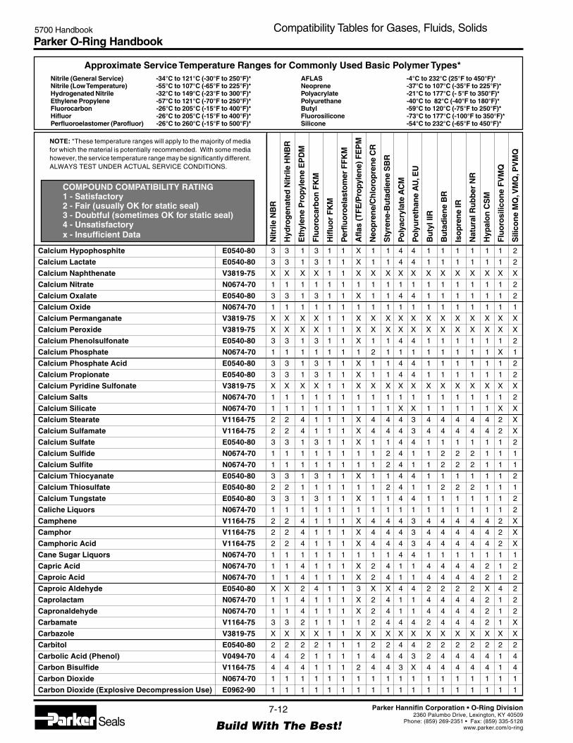
Parker O-Ring Handbook5700 Handbook Compatibility Tables for Gases, Fluids, Solids
NOTE: *These temperature ranges will apply to the majority of mediafor which the material is potentially recommended. With some mediahowever, the service temperature range may be significantly different.ALWAYS TEST UNDER ACTUAL SERVICE CONDITIONS.
Nitrile (General Service) -34°C to 121°C (-30°F to 250°F)*Nitrile (Low Temperature) -55°C to 107°C (-65°F to 225°F)*Hydrogenated Nitrile -32°C to 149°C (-23°F to 300°F)*Ethylene Propylene -57°C to 121°C (-70°F to 250°F)*Fluorocarbon -26°C to 205°C (-15°F to 400°F)*Hifluor -26°C to 205°C (-15°F to 400°F)*Perfluoroelastomer (Parofluor) -26°C to 260°C (-15°F to 500°F)*
Approximate Service Temperature Ranges for Commonly Used Basic Polymer Types*
COMPOUND COMPATIBILITY RATING1 - Satisfactory2 - Fair (usually OK for static seal)3 - Doubtful (sometimes OK for static seal)4 - Unsatisfactoryx - Insufficient Data
AFLAS -4°C to 232°C (25°F to 450°F)*Neoprene -37°C to 107°C (-35°F to 225°F)*Polyacrylate -21°C to 177°C (- 5°F to 350°F)*Polyurethane -40°C to 82°C (-40°F to 180°F)*Butyl -59°C to 120°C (-75°F to 250°F)*Fluorosilicone -73°C to 177°C (-100°F to 350°F)*Silicone -54°C to 232°C (-65°F to 450°F)*
Nitr
ile N
BR
Hyd
rog
enat
ed N
itrile
HN
BR
Eth
ylen
e P
ropy
len
e E
PD
M
Flu
oro
carb
on
FK
M
Hifl
uo
r F
KM
Per
fluo
roel
asto
mer
FF
KM
Afla
s (T
FE
/Pro
pyle
ne)
FE
PM
Neo
pre
ne/
Ch
loro
pre
ne
CR
Sty
ren
e-B
uta
die
ne
SB
R
Po
lyac
ryla
te A
CM
Po
lyu
reth
ane
AU
, EU
Bu
tyl I
IR
Bu
tad
ien
e B
R
Iso
pre
ne
IR
Nat
ura
l Ru
bb
er N
R
Hyp
alo
n C
SM
Flu
oro
silic
on
e F
VM
Q
Sili
con
e M
Q, V
MQ
, PV
MQ
7-12
Build With The Best!SealsParker Hannifin Corporation • O-Ring Division
2360 Palumbo Drive, Lexington, KY 40509Phone: (859) 269-2351 • Fax: (859) 335-5128
www.parker.com/o-ring
Calcium Hypophosphite E0540-80 3 3 1 3 1 1 X 1 1 4 4 1 1 1 1 1 1 2
Calcium Lactate E0540-80 3 3 1 3 1 1 X 1 1 4 4 1 1 1 1 1 1 2
Calcium Naphthenate V3819-75 X X X X 1 1 X X X X X X X X X X X X
Calcium Nitrate N0674-70 1 1 1 1 1 1 1 1 1 1 1 1 1 1 1 1 1 2
Calcium Oxalate E0540-80 3 3 1 3 1 1 X 1 1 4 4 1 1 1 1 1 1 2
Calcium Oxide N0674-70 1 1 1 1 1 1 1 1 1 1 1 1 1 1 1 1 1 1
Calcium Permanganate V3819-75 X X X X 1 1 X X X X X X X X X X X X
Calcium Peroxide V3819-75 X X X X 1 1 X X X X X X X X X X X X
Calcium Phenolsulfonate E0540-80 3 3 1 3 1 1 X 1 1 4 4 1 1 1 1 1 1 2
Calcium Phosphate N0674-70 1 1 1 1 1 1 1 2 1 1 1 1 1 1 1 1 X 1
Calcium Phosphate Acid E0540-80 3 3 1 3 1 1 X 1 1 4 4 1 1 1 1 1 1 2
Calcium Propionate E0540-80 3 3 1 3 1 1 X 1 1 4 4 1 1 1 1 1 1 2
Calcium Pyridine Sulfonate V3819-75 X X X X 1 1 X X X X X X X X X X X X
Calcium Salts N0674-70 1 1 1 1 1 1 1 1 1 1 1 1 1 1 1 1 1 2
Calcium Silicate N0674-70 1 1 1 1 1 1 1 1 1 X X 1 1 1 1 1 X X
Calcium Stearate V1164-75 2 2 4 1 1 1 X 4 4 4 3 4 4 4 4 4 2 X
Calcium Sulfamate V1164-75 2 2 4 1 1 1 X 4 4 4 3 4 4 4 4 4 2 X
Calcium Sulfate E0540-80 3 3 1 3 1 1 X 1 1 4 4 1 1 1 1 1 1 2
Calcium Sulfide N0674-70 1 1 1 1 1 1 1 1 2 4 1 1 2 2 2 1 1 1
Calcium Sulfite N0674-70 1 1 1 1 1 1 1 1 2 4 1 1 2 2 2 1 1 1
Calcium Thiocyanate E0540-80 3 3 1 3 1 1 X 1 1 4 4 1 1 1 1 1 1 2
Calcium Thiosulfate E0540-80 2 2 1 1 1 1 1 1 2 4 1 1 2 2 2 1 1 1
Calcium Tungstate E0540-80 3 3 1 3 1 1 X 1 1 4 4 1 1 1 1 1 1 2
Caliche Liquors N0674-70 1 1 1 1 1 1 1 1 1 1 1 1 1 1 1 1 1 2
Camphene V1164-75 2 2 4 1 1 1 X 4 4 4 3 4 4 4 4 4 2 X
Camphor V1164-75 2 2 4 1 1 1 X 4 4 4 3 4 4 4 4 4 2 X
Camphoric Acid V1164-75 2 2 4 1 1 1 X 4 4 4 3 4 4 4 4 4 2 X
Cane Sugar Liquors N0674-70 1 1 1 1 1 1 1 1 1 4 4 1 1 1 1 1 1 1
Capric Acid N0674-70 1 1 4 1 1 1 X 2 4 1 1 4 4 4 4 2 1 2
Caproic Acid N0674-70 1 1 4 1 1 1 X 2 4 1 1 4 4 4 4 2 1 2
Caproic Aldehyde E0540-80 X X 2 4 1 1 3 X X 4 4 2 2 2 2 X 4 2
Caprolactam N0674-70 1 1 4 1 1 1 X 2 4 1 1 4 4 4 4 2 1 2
Capronaldehyde N0674-70 1 1 4 1 1 1 X 2 4 1 1 4 4 4 4 2 1 2
Carbamate V1164-75 3 3 2 1 1 1 1 2 4 4 4 2 4 4 4 2 1 X
Carbazole V3819-75 X X X X 1 1 X X X X X X X X X X X X
Carbitol E0540-80 2 2 2 2 1 1 1 2 2 4 4 2 2 2 2 2 2 2
Carbolic Acid (Phenol) V0494-70 4 4 2 1 1 1 1 4 4 4 3 2 4 4 4 4 1 4
Carbon Bisulfide V1164-75 4 4 4 1 1 1 2 4 4 3 X 4 4 4 4 4 1 4
Carbon Dioxide N0674-70 1 1 1 1 1 1 1 1 1 1 1 1 1 1 1 1 1 1
Carbon Dioxide (Explosive Decompression Use) E0962-90 1 1 1 1 1 1 1 1 1 1 1 1 1 1 1 1 1 1

Parker O-Ring Handbook5700 Handbook Compatibility Tables for Gases, Fluids, Solids
NOTE: *These temperature ranges will apply to the majority of mediafor which the material is potentially recommended. With some mediahowever, the service temperature range may be significantly different.ALWAYS TEST UNDER ACTUAL SERVICE CONDITIONS.
Nitrile (General Service) -34°C to 121°C (-30°F to 250°F)*Nitrile (Low Temperature) -55°C to 107°C (-65°F to 225°F)*Hydrogenated Nitrile -32°C to 149°C (-23°F to 300°F)*Ethylene Propylene -57°C to 121°C (-70°F to 250°F)*Fluorocarbon -26°C to 205°C (-15°F to 400°F)*Hifluor -26°C to 205°C (-15°F to 400°F)*Perfluoroelastomer (Parofluor) -26°C to 260°C (-15°F to 500°F)*
Approximate Service Temperature Ranges for Commonly Used Basic Polymer Types*
COMPOUND COMPATIBILITY RATING1 - Satisfactory2 - Fair (usually OK for static seal)3 - Doubtful (sometimes OK for static seal)4 - Unsatisfactoryx - Insufficient Data
AFLAS -4°C to 232°C (25°F to 450°F)*Neoprene -37°C to 107°C (-35°F to 225°F)*Polyacrylate -21°C to 177°C (- 5°F to 350°F)*Polyurethane -40°C to 82°C (-40°F to 180°F)*Butyl -59°C to 120°C (-75°F to 250°F)*Fluorosilicone -73°C to 177°C (-100°F to 350°F)*Silicone -54°C to 232°C (-65°F to 450°F)*
Nitr
ile N
BR
Hyd
rog
enat
ed N
itrile
HN
BR
Eth
ylen
e P
ropy
len
e E
PD
M
Flu
oro
carb
on
FK
M
Hifl
uo
r F
KM
Per
fluo
roel
asto
mer
FF
KM
Afla
s (T
FE
/Pro
pyle
ne)
FE
PM
Neo
pre
ne/
Ch
loro
pre
ne
CR
Sty
ren
e-B
uta
die
ne
SB
R
Po
lyac
ryla
te A
CM
Po
lyu
reth
ane
AU
, EU
Bu
tyl I
IR
Bu
tad
ien
e B
R
Iso
pre
ne
IR
Nat
ura
l Ru
bb
er N
R
Hyp
alo
n C
SM
Flu
oro
silic
on
e F
VM
Q
Sili
con
e M
Q, V
MQ
, PV
MQ
7-13
Build With The Best!SealsParker Hannifin Corporation • O-Ring Division
2360 Palumbo Drive, Lexington, KY 40509Phone: (859) 269-2351 • Fax: (859) 335-5128
www.parker.com/o-ring
Carbon Disulfide V1164-75 4 4 4 1 1 1 2 4 4 3 X 4 4 4 4 4 1 4
Carbon Fluorides V1164-75 2 2 4 1 1 1 2 4 4 4 4 4 4 4 4 4 2 4
Carbon Monoxide N0674-70 1 1 1 1 1 1 1 2 2 X 1 1 2 2 2 2 2 1
Carbon Tetrabromide V1164-75 X X X X 1 1 X X X X X X X X X X X X
Carbon Tetrachloride V1164-75 2 2 4 1 1 1 2 4 4 4 4 4 4 4 4 4 2 4
Carbon Tetrafluoride V1164-75 2 2 4 1 1 1 2 4 4 4 4 4 4 4 4 4 2 4
Carbonic Acid E0540-80 2 2 1 1 1 1 1 1 2 1 1 1 2 1 1 1 1 1
Casein E0540-80 3 3 1 3 1 1 X 1 1 4 4 1 1 1 1 1 1 2
Castor Oil N0674-70 1 1 2 1 1 1 1 1 1 1 1 2 1 1 1 1 1 1
Caustic Lime E0540-80 3 3 1 3 1 1 X 1 1 4 4 1 1 1 1 1 1 2
Caustic Potash E0540-80 3 3 1 3 1 1 X 1 1 4 4 1 1 1 1 1 1 2
Caustic Soda (Sodium Hydroxide) E0540-80 3 3 1 3 1 1 X 1 1 4 4 1 1 1 1 1 1 2
Cellosolve E0540-80 4 4 2 4 1 1 3 4 4 4 4 2 4 4 4 4 4 4
Cellosolve, Acetate E0540-80 4 4 2 4 1 1 2 4 4 4 4 2 4 4 4 4 4 4
Cellosolve, Butyl E0540-80 4 4 2 4 1 1 2 4 4 4 4 2 4 4 4 4 4 4
Celluguard N0674-70 1 1 1 1 1 1 1 1 1 3 4 1 1 1 1 1 1 1
Cellulose Acetate E0540-80 3 3 1 3 2 1 X 1 1 4 4 1 1 1 1 1 1 2
Cellulose Acetate Butyrate E0540-80 3 3 1 3 1 1 X 1 1 4 4 1 1 1 1 1 1 2
Cellulose Ether E0540-80 3 3 1 3 2 1 X 1 1 4 4 1 1 1 1 1 1 2
Cellulose Nitrate * E0540-80 3 3 1 3 1 1 X 1 1 4 4 1 1 1 1 1 1 2
Cellulose Tripropionate E0540-80 3 3 1 3 1 1 X 1 1 4 4 1 1 1 1 1 1 2
Cellulube (Phosphate Esters) V3819-75 X X X X 1 1 X X X X X X X X X X X X
Cellutherm 2505A V1164-75 2 2 4 1 1 1 2 4 4 2 4 4 4 4 4 4 2 4
Cerium Sulfate E0540-80 3 3 1 3 1 1 X 1 1 4 4 1 1 1 1 1 1 2
Cerous Chloride E0540-80 3 3 1 3 1 1 X 1 1 4 4 1 1 1 1 1 1 2
Cerous Fluoride E0540-80 3 3 1 3 1 1 X 1 1 4 4 1 1 1 1 1 1 2
Cerous Nitrate E0540-80 3 3 1 3 1 1 X 1 1 4 4 1 1 1 1 1 1 2
Cetane (Hexadecane) N0674-70 1 1 4 1 1 1 2 2 4 1 4 4 4 4 4 2 3 4
Cetyl Alcohol N0674-70 1 1 4 1 1 1 X 2 4 1 1 4 4 4 4 2 1 2
Chaulmoogric Acid V3819-75 X X X X 1 1 X X X X X X X X X X X X
China Wood Oil (Tung Oil) N0674-70 1 1 4 1 1 1 2 2 4 X 3 3 4 4 4 3 2 4
Chloral E0540-80 3 3 1 3 1 1 X 1 1 4 4 1 1 1 1 1 1 2
Chloramine E1235-80 X X X X 1 1 X X X X X X X X X X X X
Chloranthraquinone V1164-75 2 2 4 1 2 1 X 4 4 4 3 4 4 4 4 4 2 X
Chlordane V1164-75 2 2 4 1 1 1 2 3 4 X X 4 4 4 4 3 2 4
Chlorextol V1164-75 2 2 4 1 1 1 2 2 4 2 4 4 4 4 4 4 2 4
Chloric Acid E0540-80 3 3 1 3 1 1 X 1 1 4 4 1 1 1 1 1 1 2
Chlorinated Solvents, Dry V1164-75 4 4 4 1 1 1 2 4 4 4 4 4 4 4 4 4 1 4
Chlorinated Solvents, Wet V1164-75 4 4 4 1 1 1 2 4 4 4 4 4 4 4 4 4 1 4
Chlorine (Dry) V1164-75 2 2 4 1 1 1 X 4 4 4 3 4 4 4 4 4 2 X

Parker O-Ring Handbook5700 Handbook Compatibility Tables for Gases, Fluids, Solids
NOTE: *These temperature ranges will apply to the majority of mediafor which the material is potentially recommended. With some mediahowever, the service temperature range may be significantly different.ALWAYS TEST UNDER ACTUAL SERVICE CONDITIONS.
Nitrile (General Service) -34°C to 121°C (-30°F to 250°F)*Nitrile (Low Temperature) -55°C to 107°C (-65°F to 225°F)*Hydrogenated Nitrile -32°C to 149°C (-23°F to 300°F)*Ethylene Propylene -57°C to 121°C (-70°F to 250°F)*Fluorocarbon -26°C to 205°C (-15°F to 400°F)*Hifluor -26°C to 205°C (-15°F to 400°F)*Perfluoroelastomer (Parofluor) -26°C to 260°C (-15°F to 500°F)*
Approximate Service Temperature Ranges for Commonly Used Basic Polymer Types*
COMPOUND COMPATIBILITY RATING1 - Satisfactory2 - Fair (usually OK for static seal)3 - Doubtful (sometimes OK for static seal)4 - Unsatisfactoryx - Insufficient Data
AFLAS -4°C to 232°C (25°F to 450°F)*Neoprene -37°C to 107°C (-35°F to 225°F)*Polyacrylate -21°C to 177°C (- 5°F to 350°F)*Polyurethane -40°C to 82°C (-40°F to 180°F)*Butyl -59°C to 120°C (-75°F to 250°F)*Fluorosilicone -73°C to 177°C (-100°F to 350°F)*Silicone -54°C to 232°C (-65°F to 450°F)*
Nitr
ile N
BR
Hyd
rog
enat
ed N
itrile
HN
BR
Eth
ylen
e P
ropy
len
e E
PD
M
Flu
oro
carb
on
FK
M
Hifl
uo
r F
KM
Per
fluo
roel
asto
mer
FF
KM
Afla
s (T
FE
/Pro
pyle
ne)
FE
PM
Neo
pre
ne/
Ch
loro
pre
ne
CR
Sty
ren
e-B
uta
die
ne
SB
R
Po
lyac
ryla
te A
CM
Po
lyu
reth
ane
AU
, EU
Bu
tyl I
IR
Bu
tad
ien
e B
R
Iso
pre
ne
IR
Nat
ura
l Ru
bb
er N
R
Hyp
alo
n C
SM
Flu
oro
silic
on
e F
VM
Q
Sili
con
e M
Q, V
MQ
, PV
MQ
7-14
Build With The Best!SealsParker Hannifin Corporation • O-Ring Division
2360 Palumbo Drive, Lexington, KY 40509Phone: (859) 269-2351 • Fax: (859) 335-5128
www.parker.com/o-ring
Chlorine (Plasma) V3819-75 X X X X 3 2 X X X X X X X X X X X X
Chlorine (Wet) V3819-75 X X X X 2 2 X X X X X X X X X X X X
Chlorine Dioxide V1164-75 4 4 3 1 1 1 2 4 4 4 4 3 4 4 4 3 2 X
Chlorine Dioxide, 8% Cl as NaClO2 in solution V1164-75 4 4 4 1 1 1 2 4 4 4 4 4 4 4 4 4 2 X
Chlorine Trifluoride Factory 4 4 4 4 2 2 4 4 4 4 4 4 4 4 4 4 4 4
Chlorine Water V1164-75 3 3 2 1 1 1 1 4 X X X X X X X X X X
Chloro 1-Nitro Ethane (1-Chloro 1-Nitro Ethane) Factory 4 4 4 4 1 1 3 4 4 4 4 4 4 4 4 4 4 4
Chloro Oxyfluorides V3819-75 X X X X 2 2 X X X X X X X X X X X X
Chloro Xylenols V1164-75 2 2 4 1 1 1 X 4 4 4 3 4 4 4 4 4 2 X
Chloroacetaldehyde E0540-80 3 3 1 3 2 2 X 1 1 4 4 1 1 1 1 1 1 2
Chloroacetic Acid E0540-80 4 4 2 4 1 1 2 4 4 4 4 2 4 4 4 1 4 X
Chloroacetone E0540-80 4 4 1 4 2 1 2 4 4 4 4 2 4 4 4 4 4 4
Chloroacetyl Chloride V3819-75 X X X X 1 1 X X X X X X X X X X X X
Chloroamino Benzoic Acid E0540-80 3 3 1 3 1 1 X 1 1 4 4 1 1 1 1 1 1 2
Chloroaniline E0540-80 3 3 1 3 1 1 X 1 1 4 4 1 1 1 1 1 1 2
Chlorobenzaldehyde E0540-80 3 3 1 3 1 1 X 1 1 4 4 1 1 1 1 1 1 2
Chlorobenzene V1164-75 4 4 4 1 1 1 2 4 4 4 4 4 4 4 4 4 2 4
Chlorobenzene (Mono) V1164-75 4 4 4 1 1 1 2 4 4 4 4 4 4 4 4 4 2 4
Chlorobenzene Chloride V1164-75 2 2 4 1 1 1 X 4 4 4 3 4 4 4 4 4 2 X
Chlorobenzene Trifluoride V1164-75 2 2 4 1 1 1 X 4 4 4 3 4 4 4 4 4 2 X
Chlorobenzochloride V1164-75 2 2 4 1 1 1 X 4 4 4 3 4 4 4 4 4 2 X
Chlorobenzotrifluoride V1164-75 2 2 4 1 1 1 X 4 4 4 3 4 4 4 4 4 2 X
Chlorobromo Methane V1164-75 4 4 2 1 1 1 1 4 4 4 4 2 4 4 4 4 2 4
Chlorobromopropane V1164-75 2 2 4 1 1 1 X 4 4 4 3 4 4 4 4 4 2 X
Chlorobutadiene V1164-75 4 4 4 1 1 1 2 4 4 4 4 4 4 4 4 4 2 4
Chlorobutane (Butyl Chloride) N0674-70 1 1 4 1 1 1 X 2 4 1 1 4 4 4 4 2 1 2
Chlorododecane V1164-75 4 4 4 1 1 1 2 4 4 4 4 4 4 4 4 4 1 4
Chloroethane N0674-70 1 1 4 1 1 1 X 2 4 1 1 4 4 4 4 2 1 2
Chloroethane Sulfonic Acid E0540-80 3 3 1 3 1 1 X 1 1 4 4 1 1 1 1 1 1 2
Chloroethylbenzene V1164-75 2 2 4 1 1 1 X 4 4 4 3 4 4 4 4 4 2 X
Chloroform V1164-75 4 4 4 1 1 1 2 4 4 4 4 4 4 4 4 4 4 4
Chlorohydrin E0540-80 3 3 1 3 1 1 X 1 1 4 4 1 1 1 1 1 1 2
Chloronaphthalene or o-Chloronaphthalene V1164-75 4 4 4 1 1 1 X 4 4 4 4 4 4 4 4 4 2 4
Chloronitrobenzene E0540-80 3 3 1 3 1 1 X 1 1 4 4 1 1 1 1 1 1 2
Chlorophenol or o-Chlorophenol V1164-75 4 4 4 1 1 1 X 4 4 4 4 4 4 4 4 4 2 4
Chloropicrin V1164-75 2 2 4 1 1 1 X 4 4 4 3 4 4 4 4 4 2 X
Chloroprene V1164-75 2 2 4 1 1 1 X 4 4 4 3 4 4 4 4 4 2 X
Chlorosilanes V3819-75 X X X X 1 1 X X X X X X X X X X X X
Chlorosulfonic Acid Factory 4 4 4 4 1 1 4 4 4 4 4 4 4 4 4 4 4 4
Chlorotoluene V1164-75 4 4 4 1 1 1 2 4 4 4 4 4 4 4 4 4 2 4
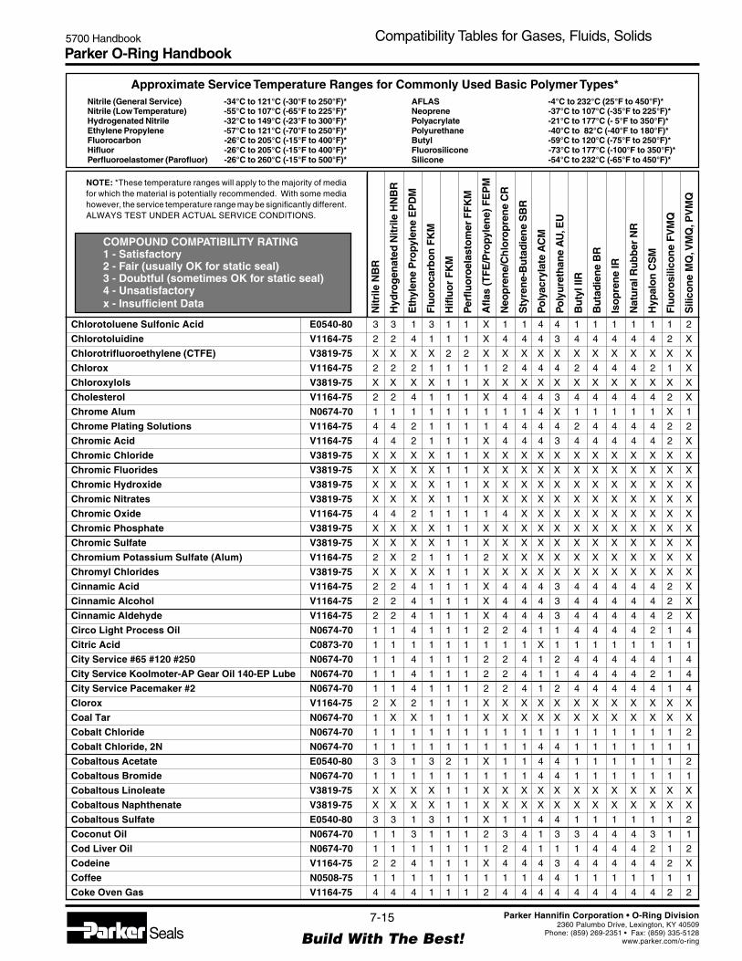
Parker O-Ring Handbook5700 Handbook Compatibility Tables for Gases, Fluids, Solids
NOTE: *These temperature ranges will apply to the majority of mediafor which the material is potentially recommended. With some mediahowever, the service temperature range may be significantly different.ALWAYS TEST UNDER ACTUAL SERVICE CONDITIONS.
Nitrile (General Service) -34°C to 121°C (-30°F to 250°F)*Nitrile (Low Temperature) -55°C to 107°C (-65°F to 225°F)*Hydrogenated Nitrile -32°C to 149°C (-23°F to 300°F)*Ethylene Propylene -57°C to 121°C (-70°F to 250°F)*Fluorocarbon -26°C to 205°C (-15°F to 400°F)*Hifluor -26°C to 205°C (-15°F to 400°F)*Perfluoroelastomer (Parofluor) -26°C to 260°C (-15°F to 500°F)*
Approximate Service Temperature Ranges for Commonly Used Basic Polymer Types*
COMPOUND COMPATIBILITY RATING1 - Satisfactory2 - Fair (usually OK for static seal)3 - Doubtful (sometimes OK for static seal)4 - Unsatisfactoryx - Insufficient Data
AFLAS -4°C to 232°C (25°F to 450°F)*Neoprene -37°C to 107°C (-35°F to 225°F)*Polyacrylate -21°C to 177°C (- 5°F to 350°F)*Polyurethane -40°C to 82°C (-40°F to 180°F)*Butyl -59°C to 120°C (-75°F to 250°F)*Fluorosilicone -73°C to 177°C (-100°F to 350°F)*Silicone -54°C to 232°C (-65°F to 450°F)*
Nitr
ile N
BR
Hyd
rog
enat
ed N
itrile
HN
BR
Eth
ylen
e P
ropy
len
e E
PD
M
Flu
oro
carb
on
FK
M
Hifl
uo
r F
KM
Per
fluo
roel
asto
mer
FF
KM
Afla
s (T
FE
/Pro
pyle
ne)
FE
PM
Neo
pre
ne/
Ch
loro
pre
ne
CR
Sty
ren
e-B
uta
die
ne
SB
R
Po
lyac
ryla
te A
CM
Po
lyu
reth
ane
AU
, EU
Bu
tyl I
IR
Bu
tad
ien
e B
R
Iso
pre
ne
IR
Nat
ura
l Ru
bb
er N
R
Hyp
alo
n C
SM
Flu
oro
silic
on
e F
VM
Q
Sili
con
e M
Q, V
MQ
, PV
MQ
7-15
Build With The Best!SealsParker Hannifin Corporation • O-Ring Division
2360 Palumbo Drive, Lexington, KY 40509Phone: (859) 269-2351 • Fax: (859) 335-5128
www.parker.com/o-ring
Chlorotoluene Sulfonic Acid E0540-80 3 3 1 3 1 1 X 1 1 4 4 1 1 1 1 1 1 2
Chlorotoluidine V1164-75 2 2 4 1 1 1 X 4 4 4 3 4 4 4 4 4 2 X
Chlorotrifluoroethylene (CTFE) V3819-75 X X X X 2 2 X X X X X X X X X X X X
Chlorox V1164-75 2 2 2 1 1 1 1 2 4 4 4 2 4 4 4 2 1 X
Chloroxylols V3819-75 X X X X 1 1 X X X X X X X X X X X X
Cholesterol V1164-75 2 2 4 1 1 1 X 4 4 4 3 4 4 4 4 4 2 X
Chrome Alum N0674-70 1 1 1 1 1 1 1 1 1 4 X 1 1 1 1 1 X 1
Chrome Plating Solutions V1164-75 4 4 2 1 1 1 1 4 4 4 4 2 4 4 4 4 2 2
Chromic Acid V1164-75 4 4 2 1 1 1 X 4 4 4 3 4 4 4 4 4 2 X
Chromic Chloride V3819-75 X X X X 1 1 X X X X X X X X X X X X
Chromic Fluorides V3819-75 X X X X 1 1 X X X X X X X X X X X X
Chromic Hydroxide V3819-75 X X X X 1 1 X X X X X X X X X X X X
Chromic Nitrates V3819-75 X X X X 1 1 X X X X X X X X X X X X
Chromic Oxide V1164-75 4 4 2 1 1 1 1 4 X X X X X X X X X X
Chromic Phosphate V3819-75 X X X X 1 1 X X X X X X X X X X X X
Chromic Sulfate V3819-75 X X X X 1 1 X X X X X X X X X X X X
Chromium Potassium Sulfate (Alum) V1164-75 2 X 2 1 1 1 2 X X X X X X X X X X X
Chromyl Chlorides V3819-75 X X X X 1 1 X X X X X X X X X X X X
Cinnamic Acid V1164-75 2 2 4 1 1 1 X 4 4 4 3 4 4 4 4 4 2 X
Cinnamic Alcohol V1164-75 2 2 4 1 1 1 X 4 4 4 3 4 4 4 4 4 2 X
Cinnamic Aldehyde V1164-75 2 2 4 1 1 1 X 4 4 4 3 4 4 4 4 4 2 X
Circo Light Process Oil N0674-70 1 1 4 1 1 1 2 2 4 1 1 4 4 4 4 2 1 4
Citric Acid C0873-70 1 1 1 1 1 1 1 1 1 X 1 1 1 1 1 1 1 1
City Service #65 #120 #250 N0674-70 1 1 4 1 1 1 2 2 4 1 2 4 4 4 4 4 1 4
City Service Koolmoter-AP Gear Oil 140-EP Lube N0674-70 1 1 4 1 1 1 2 2 4 1 1 4 4 4 4 2 1 4
City Service Pacemaker #2 N0674-70 1 1 4 1 1 1 2 2 4 1 2 4 4 4 4 4 1 4
Clorox V1164-75 2 X 2 1 1 1 X X X X X X X X X X X X
Coal Tar N0674-70 1 X X 1 1 1 X X X X X X X X X X X X
Cobalt Chloride N0674-70 1 1 1 1 1 1 1 1 1 1 1 1 1 1 1 1 1 2
Cobalt Chloride, 2N N0674-70 1 1 1 1 1 1 1 1 1 4 4 1 1 1 1 1 1 1
Cobaltous Acetate E0540-80 3 3 1 3 2 1 X 1 1 4 4 1 1 1 1 1 1 2
Cobaltous Bromide N0674-70 1 1 1 1 1 1 1 1 1 4 4 1 1 1 1 1 1 1
Cobaltous Linoleate V3819-75 X X X X 1 1 X X X X X X X X X X X X
Cobaltous Naphthenate V3819-75 X X X X 1 1 X X X X X X X X X X X X
Cobaltous Sulfate E0540-80 3 3 1 3 1 1 X 1 1 4 4 1 1 1 1 1 1 2
Coconut Oil N0674-70 1 1 3 1 1 1 2 3 4 1 3 3 4 4 4 3 1 1
Cod Liver Oil N0674-70 1 1 1 1 1 1 1 2 4 1 1 1 4 4 4 2 1 2
Codeine V1164-75 2 2 4 1 1 1 X 4 4 4 3 4 4 4 4 4 2 X
Coffee N0508-75 1 1 1 1 1 1 1 1 1 4 4 1 1 1 1 1 1 1
Coke Oven Gas V1164-75 4 4 4 1 1 1 2 4 4 4 4 4 4 4 4 4 2 2

Parker O-Ring Handbook5700 Handbook Compatibility Tables for Gases, Fluids, Solids
NOTE: *These temperature ranges will apply to the majority of mediafor which the material is potentially recommended. With some mediahowever, the service temperature range may be significantly different.ALWAYS TEST UNDER ACTUAL SERVICE CONDITIONS.
Nitrile (General Service) -34°C to 121°C (-30°F to 250°F)*Nitrile (Low Temperature) -55°C to 107°C (-65°F to 225°F)*Hydrogenated Nitrile -32°C to 149°C (-23°F to 300°F)*Ethylene Propylene -57°C to 121°C (-70°F to 250°F)*Fluorocarbon -26°C to 205°C (-15°F to 400°F)*Hifluor -26°C to 205°C (-15°F to 400°F)*Perfluoroelastomer (Parofluor) -26°C to 260°C (-15°F to 500°F)*
Approximate Service Temperature Ranges for Commonly Used Basic Polymer Types*
COMPOUND COMPATIBILITY RATING1 - Satisfactory2 - Fair (usually OK for static seal)3 - Doubtful (sometimes OK for static seal)4 - Unsatisfactoryx - Insufficient Data
AFLAS -4°C to 232°C (25°F to 450°F)*Neoprene -37°C to 107°C (-35°F to 225°F)*Polyacrylate -21°C to 177°C (- 5°F to 350°F)*Polyurethane -40°C to 82°C (-40°F to 180°F)*Butyl -59°C to 120°C (-75°F to 250°F)*Fluorosilicone -73°C to 177°C (-100°F to 350°F)*Silicone -54°C to 232°C (-65°F to 450°F)*
Nitr
ile N
BR
Hyd
rog
enat
ed N
itrile
HN
BR
Eth
ylen
e P
ropy
len
e E
PD
M
Flu
oro
carb
on
FK
M
Hifl
uo
r F
KM
Per
fluo
roel
asto
mer
FF
KM
Afla
s (T
FE
/Pro
pyle
ne)
FE
PM
Neo
pre
ne/
Ch
loro
pre
ne
CR
Sty
ren
e-B
uta
die
ne
SB
R
Po
lyac
ryla
te A
CM
Po
lyu
reth
ane
AU
, EU
Bu
tyl I
IR
Bu
tad
ien
e B
R
Iso
pre
ne
IR
Nat
ura
l Ru
bb
er N
R
Hyp
alo
n C
SM
Flu
oro
silic
on
e F
VM
Q
Sili
con
e M
Q, V
MQ
, PV
MQ
7-16
Build With The Best!SealsParker Hannifin Corporation • O-Ring Division
2360 Palumbo Drive, Lexington, KY 40509Phone: (859) 269-2351 • Fax: (859) 335-5128
www.parker.com/o-ring
Coliche Liquors C0873-70 2 2 2 X X X 2 1 2 X X 2 1 1 1 X X X
Convelex 10 Factory 4 4 X X X X X 4 4 X 2 4 4 4 4 4 X 4
Coolanol 20 25R 35R 40& 45A (Monsanto) V1164-75 1 1 3 1 1 1 2 2 4 4 1 4 4 4 4 2 1 4
Copper Acetate E0540-80 2 2 1 4 1 1 2 2 4 4 4 1 4 1 1 2 4 4
Copper Ammonium Acetate E0540-80 3 3 1 3 1 1 X 1 1 4 4 1 1 1 1 1 1 2
Copper Carbonate E0540-80 3 3 1 3 1 1 X 1 1 4 4 1 1 1 1 1 1 2
Copper Chloride N0674-70 1 1 1 1 1 1 1 2 1 1 1 1 1 1 1 2 1 1
Copper Cyanide N0674-70 1 1 1 1 1 1 1 1 1 1 1 1 1 1 1 1 1 1
Copper Gluconate E0540-80 3 3 1 3 1 1 X 1 1 4 4 1 1 1 1 1 1 2
Copper Naphthenate V3819-75 X X X X 1 1 X X X X X X X X X X X X
Copper Nitrate V1164-75 2 X 2 1 1 1 2 X X X X X X X X X X X
Copper Oxide N0674-70 1 1 1 1 1 1 1 1 1 1 1 1 1 1 1 1 1 1
Copper Salts N0674-70 1 1 1 1 1 1 1 1 1 1 1 1 1 1 1 1 1 1
Copper Sulfate N0674-70 1 1 1 1 1 1 1 1 2 4 1 2 2 2 2 1 1 1
Copper Sulfate 10% N0674-70 1 1 1 1 1 1 1 1 2 4 2 2 2 2 2 1 1 1
Copper Sulfate 50% N0674-70 1 1 1 1 1 1 1 1 2 4 3 2 2 2 1 1 1 1
Corn Oil N0674-70 1 1 3 1 1 1 2 3 4 1 1 3 4 4 4 2 1 1
Cottonseed Oil N0674-70 1 1 3 1 1 1 2 3 4 1 1 3 4 4 4 2 2 1
Creosote, Coal Tar N0674-70 1 1 4 1 1 1 2 2 4 1 3 4 4 4 4 4 1 4
Creosote, Wood N0674-70 1 1 4 1 1 1 2 2 4 1 3 4 4 4 4 4 1 4
Cresol (Methyl Phenol) V1164-75 X X X 1 1 1 X X X X X X X X X X X X
Cresols V0834-70 4 4 4 2 1 1 2 4 4 4 X 4 4 4 4 4 X 4
Cresylic Acid V0834-70 4 4 4 1 1 1 2 4 4 4 4 4 4 4 4 4 X 4
Crotonaldehyde V1164-75 2 2 4 1 1 1 X 4 4 4 3 4 4 4 4 4 2 X
Crotonic Acid V1164-75 2 2 4 1 1 1 X 4 4 4 3 4 4 4 4 4 2 X
Crude Oil V1164-75 2 2 4 1 1 1 2 4 4 1 X 4 4 4 4 4 2 4
Cumaldehyde V1164-75 2 2 4 1 1 1 X 4 4 4 3 4 4 4 4 4 2 X
Cumene V1164-75 4 4 4 1 1 1 2 4 4 4 4 4 4 4 4 4 2 4
Cumene Hydroperoxide V3819-75 X X X X 1 1 X X X X X X X X X X X X
Cupric Sulfate V1164-75 2 X 2 1 1 1 2 X X X X X X X X X X X
Cutting Oil N0674-70 1 1 4 1 1 1 2 2 4 1 1 4 4 4 4 2 1 4
Cyanamide V3819-75 X X X X 1 1 X X X X X X X X X X X X
Cyanides V3819-75 X X X X 1 1 X X X X X X X X X X X X
Cyanogen Chloride V3819-75 X X X X 1 1 X X X X X X X X X X X X
Cyanogen Gas V3819-75 X X X X 1 1 X X X X X X X X X X X X
Cyanohydrin V3819-75 X X X X 1 1 X X X X X X X X X X X X
Cyanuric Chloride V3819-75 X X X X 1 1 X X X X X X X X X X X X
Cyclohexane N0674-70 1 1 4 1 1 1 2 3 4 2 1 4 4 4 4 4 1 4
Cyclohexanol N0674-70 1 1 4 1 1 1 2 2 4 X X 4 4 4 4 2 1 4
Cyclohexanone E0540-80 4 4 2 4 1 1 3 4 4 4 4 2 4 4 4 4 4 4

Parker O-Ring Handbook5700 Handbook Compatibility Tables for Gases, Fluids, Solids
NOTE: *These temperature ranges will apply to the majority of mediafor which the material is potentially recommended. With some mediahowever, the service temperature range may be significantly different.ALWAYS TEST UNDER ACTUAL SERVICE CONDITIONS.
Nitrile (General Service) -34°C to 121°C (-30°F to 250°F)*Nitrile (Low Temperature) -55°C to 107°C (-65°F to 225°F)*Hydrogenated Nitrile -32°C to 149°C (-23°F to 300°F)*Ethylene Propylene -57°C to 121°C (-70°F to 250°F)*Fluorocarbon -26°C to 205°C (-15°F to 400°F)*Hifluor -26°C to 205°C (-15°F to 400°F)*Perfluoroelastomer (Parofluor) -26°C to 260°C (-15°F to 500°F)*
Approximate Service Temperature Ranges for Commonly Used Basic Polymer Types*
COMPOUND COMPATIBILITY RATING1 - Satisfactory2 - Fair (usually OK for static seal)3 - Doubtful (sometimes OK for static seal)4 - Unsatisfactoryx - Insufficient Data
AFLAS -4°C to 232°C (25°F to 450°F)*Neoprene -37°C to 107°C (-35°F to 225°F)*Polyacrylate -21°C to 177°C (- 5°F to 350°F)*Polyurethane -40°C to 82°C (-40°F to 180°F)*Butyl -59°C to 120°C (-75°F to 250°F)*Fluorosilicone -73°C to 177°C (-100°F to 350°F)*Silicone -54°C to 232°C (-65°F to 450°F)*
Nitr
ile N
BR
Hyd
rog
enat
ed N
itrile
HN
BR
Eth
ylen
e P
ropy
len
e E
PD
M
Flu
oro
carb
on
FK
M
Hifl
uo
r F
KM
Per
fluo
roel
asto
mer
FF
KM
Afla
s (T
FE
/Pro
pyle
ne)
FE
PM
Neo
pre
ne/
Ch
loro
pre
ne
CR
Sty
ren
e-B
uta
die
ne
SB
R
Po
lyac
ryla
te A
CM
Po
lyu
reth
ane
AU
, EU
Bu
tyl I
IR
Bu
tad
ien
e B
R
Iso
pre
ne
IR
Nat
ura
l Ru
bb
er N
R
Hyp
alo
n C
SM
Flu
oro
silic
on
e F
VM
Q
Sili
con
e M
Q, V
MQ
, PV
MQ
7-17
Build With The Best!SealsParker Hannifin Corporation • O-Ring Division
2360 Palumbo Drive, Lexington, KY 40509Phone: (859) 269-2351 • Fax: (859) 335-5128
www.parker.com/o-ring
Cyclohexene V1164-75 2 2 4 1 1 1 X 4 4 4 3 4 4 4 4 4 2 X
Cyclohexylamine N0674-70 1 1 4 1 1 1 X 2 4 1 1 4 4 4 4 2 1 2
Cyclohexylamine Carbonate V8545-75 X X X X 1 1 X X X X X X X X X X X X
Cyclohexylamine Laurate N0674-70 1 1 4 1 1 1 X 2 4 1 1 4 4 4 4 2 1 2
Cyclopentadiene V1164-75 2 2 4 1 1 1 X 4 4 4 3 4 4 4 4 4 2 X
Cyclopentane N0674-70 1 1 4 1 1 1 2 3 4 2 1 4 4 4 4 4 1 4
Cyclopolyolefins V1164-75 1 1 4 1 1 1 2 3 4 2 1 4 4 4 4 4 1 4
Cymene or p-Cymene V1164-75 4 4 4 1 1 1 X 4 4 4 4 4 4 4 4 4 2 4
— D —
DDT (Dichlorodiphenyltrichloroethane) V1164-75 2 2 4 1 1 1 X 4 4 4 3 4 4 4 4 4 2 X
Decalin V1164-75 4 4 4 1 1 1 2 4 4 X X 4 4 4 4 4 1 4
Decane N0674-70 1 1 4 1 1 1 2 3 4 1 2 4 4 4 4 3 1 2
Delco Brake Fluid E0603-70 3 3 1 4 1 1 2 2 1 X X 2 X X X 2 4 3
Denatured Alcohol N0674-70 1 1 1 1 1 1 1 1 1 4 4 1 1 1 1 1 1 1
Detergent, Water Solution E0540-80 1 1 1 1 1 1 1 2 2 4 4 1 2 2 2 2 1 1
Developing Fluids (Photo) N0674-70 1 1 2 1 1 1 1 1 2 X X 2 2 1 1 1 1 1
Dexron N0674-70 1 1 4 1 1 1 2 2 4 1 2 4 4 4 4 4 2 4
Dextrin N0674-70 1 1 4 1 1 1 X 2 4 1 1 4 4 4 4 2 1 2
Dextro Lactic Acid E0540-80 3 3 1 3 1 1 X 1 1 4 4 1 1 1 1 1 1 2
Dextron N0674-70 1 1 4 1 1 1 1 2 X X X X X X X X X X
Dextrose E0540-80 3 3 1 3 1 1 X 1 1 4 4 1 1 1 1 1 1 2
DI Water E0540-80 2 X 1 2 1 1 X 1 1 4 4 1 1 1 1 1 1 2
Diacetone E0540-80 4 4 1 4 1 1 2 4 4 4 4 1 4 4 4 4 4 4
Diacetone Alcohol E0540-80 4 4 1 4 1 1 2 2 4 4 4 1 4 4 4 2 4 4
Dialkyl Sulfates E0540-80 3 3 1 3 1 1 X 1 1 4 4 1 1 1 1 1 1 2
Diallyl Ether V3819-75 X X X X 1 1 X X X X X X X X X X X X
Diallyl Phthalate V3819-75 X X X X 1 1 X X X X X X X X X X X X
Diamylamine N0674-70 1 1 4 1 2 1 X 2 4 1 1 4 4 4 4 2 1 2
Diazinon V1164-75 3 3 4 2 1 1 2 3 4 X X 4 4 4 4 3 2 4
Dibenzyl (sym-Diphenylethane) V1164-75 2 2 4 1 1 1 X 4 4 4 3 4 4 4 4 4 2 X
Dibenzyl Ether Factory 4 4 2 4 1 1 2 4 4 X 2 2 4 4 4 4 X X
Dibenzyl Sebacate V1164-75 4 4 2 2 1 1 2 4 4 4 2 2 4 4 4 4 3 3
Diborane V3819-75 X X X X 1 1 X X X X X X X X X X X X
Dibromoethane V1164-75 2 2 4 1 1 1 X 4 4 4 3 4 4 4 4 4 2 X
Dibromoethyl Benzene V1164-75 4 4 4 1 1 1 2 4 4 4 4 4 4 4 4 4 2 4
Dibutyl Cellosolve Adipate E0540-80 3 3 1 3 1 1 X 1 1 4 4 1 1 1 1 1 1 2
Dibutyl Ether Factory 4 4 3 3 1 1 3 4 4 3 2 3 4 4 4 4 3 4
Dibutyl Methylenedithio Glycolate V1164-75 2 2 4 1 1 1 X 4 4 4 3 4 4 4 4 4 2 X
Dibutyl Phthalate E0540-80 4 4 2 3 2 1 3 4 4 4 3 3 4 4 4 4 3 2
Dibutyl Sebacate E0540-80 4 4 2 2 1 1 2 4 4 4 4 2 4 4 4 4 2 2

Parker O-Ring Handbook5700 Handbook Compatibility Tables for Gases, Fluids, Solids
NOTE: *These temperature ranges will apply to the majority of mediafor which the material is potentially recommended. With some mediahowever, the service temperature range may be significantly different.ALWAYS TEST UNDER ACTUAL SERVICE CONDITIONS.
Nitrile (General Service) -34°C to 121°C (-30°F to 250°F)*Nitrile (Low Temperature) -55°C to 107°C (-65°F to 225°F)*Hydrogenated Nitrile -32°C to 149°C (-23°F to 300°F)*Ethylene Propylene -57°C to 121°C (-70°F to 250°F)*Fluorocarbon -26°C to 205°C (-15°F to 400°F)*Hifluor -26°C to 205°C (-15°F to 400°F)*Perfluoroelastomer (Parofluor) -26°C to 260°C (-15°F to 500°F)*
Approximate Service Temperature Ranges for Commonly Used Basic Polymer Types*
COMPOUND COMPATIBILITY RATING1 - Satisfactory2 - Fair (usually OK for static seal)3 - Doubtful (sometimes OK for static seal)4 - Unsatisfactoryx - Insufficient Data
AFLAS -4°C to 232°C (25°F to 450°F)*Neoprene -37°C to 107°C (-35°F to 225°F)*Polyacrylate -21°C to 177°C (- 5°F to 350°F)*Polyurethane -40°C to 82°C (-40°F to 180°F)*Butyl -59°C to 120°C (-75°F to 250°F)*Fluorosilicone -73°C to 177°C (-100°F to 350°F)*Silicone -54°C to 232°C (-65°F to 450°F)*
Nitr
ile N
BR
Hyd
rog
enat
ed N
itrile
HN
BR
Eth
ylen
e P
ropy
len
e E
PD
M
Flu
oro
carb
on
FK
M
Hifl
uo
r F
KM
Per
fluo
roel
asto
mer
FF
KM
Afla
s (T
FE
/Pro
pyle
ne)
FE
PM
Neo
pre
ne/
Ch
loro
pre
ne
CR
Sty
ren
e-B
uta
die
ne
SB
R
Po
lyac
ryla
te A
CM
Po
lyu
reth
ane
AU
, EU
Bu
tyl I
IR
Bu
tad
ien
e B
R
Iso
pre
ne
IR
Nat
ura
l Ru
bb
er N
R
Hyp
alo
n C
SM
Flu
oro
silic
on
e F
VM
Q
Sili
con
e M
Q, V
MQ
, PV
MQ
7-18
Build With The Best!SealsParker Hannifin Corporation • O-Ring Division
2360 Palumbo Drive, Lexington, KY 40509Phone: (859) 269-2351 • Fax: (859) 335-5128
www.parker.com/o-ring
Dibutyl Thioglycolate V1164-75 2 2 4 1 1 1 X 4 4 4 3 4 4 4 4 4 2 X
Dibutyl Thiourea V1164-75 2 2 4 1 1 1 X 4 4 4 3 4 4 4 4 4 2 X
Dibutylamine E0540-80 4 4 1 4 1 1 4 3 4 4 4 4 4 4 4 4 4 3
Dichloroacetic Acid V1164-75 2 2 4 1 1 1 X 4 4 4 3 4 4 4 4 4 2 X
Dichloroaniline E0540-80 3 3 1 3 1 1 X 1 1 4 4 1 1 1 1 1 1 2
Dichlorobenzene or o-Dichlorobenzene V1164-75 4 4 4 1 1 1 4 4 4 4 4 4 4 4 4 2 4
Dichlorobenzene or p-Dichlorobenzene V1164-75 4 4 4 1 1 1 4 4 4 4 4 4 4 4 4 2 4
Dichlorobutane V1164-75 2 2 4 1 1 1 2 4 4 4 4 4 4 4 4 4 2 4
Dichlorobutene V1164-75 2 2 4 1 1 1 X 4 4 4 3 4 4 4 4 4 2 X
Dichlorodiphenyl-Dichloroethane (DDD) V1164-75 2 2 4 1 1 1 X 4 4 4 3 4 4 4 4 4 2 X
Dichloroethane V1164-75 2 2 4 1 1 1 X 4 4 4 3 4 4 4 4 4 2 X
Dichloroethylene V1164-75 2 2 4 1 1 1 X 4 4 4 3 4 4 4 4 4 2 X
Dichlorohydrin E0540-80 3 3 1 3 1 1 X 1 1 4 4 1 1 1 1 1 1 2
Dichloroisopropyl Ether Factory 4 4 3 3 1 1 3 4 4 3 2 4 4 4 4 4 3 4
Dichloromethane V1164-75 2 2 4 1 1 1 X 4 4 4 3 4 4 4 4 4 2 X
Dichlorophenol V1164-75 2 2 4 1 1 1 X 4 4 4 3 4 4 4 4 4 2 X
Dichlorophenoxyacetic Acid V1164-75 2 2 4 1 1 1 X 4 4 4 3 4 4 4 4 4 2 X
Dichloropropane V1164-75 2 2 4 1 1 1 X 4 4 4 3 4 4 4 4 4 2 X
Dichloropropene V1164-75 2 2 4 1 1 1 X 4 4 4 3 4 4 4 4 4 2 X
Dichlorosilane V3819-75 X X X X 1 1 X X X X X X X X X X X X
Dicyclohexylamine N0674-70 1 1 4 4 1 1 4 4 4 4 4 4 4 4 4 4 4 2
Dicyclohexylammonium Nitrate E0540-80 3 3 1 3 1 1 X 1 1 4 4 1 1 1 1 1 1 2
Dieldrin V1164-75 2 2 4 1 1 1 X 4 4 4 3 4 4 4 4 4 2 X
Diesel Oil N0674-70 1 1 4 1 1 1 2 3 4 1 3 4 4 4 4 3 1 4
Di-ester Lubricant MIL-L-7808 V1164-75 2 2 4 1 1 1 2 4 4 2 4 4 4 4 4 4 2 4
Di-ester Synthetic Lubricants V1164-75 2 2 4 1 1 1 2 4 4 2 4 4 4 4 4 4 2 4
Diethanolamine (DEA) E0540-80 3 3 1 3 2 1 X 1 1 4 4 1 1 1 1 1 1 2
Diethyl Benzene V1164-75 X X X 1 1 1 X X X X X X X X X X X X
Diethyl Carbonate E0540-80 3 3 1 3 1 1 X 1 1 4 4 1 1 1 1 1 1 2
Diethyl Ether Factory 4 4 4 4 1 1 4 3 4 3 1 4 4 4 4 4 3 4
Diethyl Phthalate V1164-75 2 2 4 1 1 1 X 4 4 4 3 4 4 4 4 4 2 X
Diethyl Sebacate V1164-75 2 2 2 2 1 1 2 4 4 4 4 2 4 4 4 4 2 2
Diethyl Sulfate E0540-80 4 X 1 3 1 1 2 4 X X X X X X X X X 2
Diethylamine E0540-80 2 X 1 4 1 1 X 1 1 4 4 1 1 1 1 1 1 2
Diethylaniline E0540-80 3 3 1 3 1 1 X 1 1 4 4 1 1 1 1 1 1 2
Diethylene Glycol E0540-80 1 1 1 1 1 1 1 1 1 2 4 1 1 1 1 1 1 2
Diethylenetriamine V8545-75 X X X X 1 1 X X X X X X X X X X X X
Difluorodibromomethane E0540-80 4 4 2 X 1 1 2 4 4 4 4 2 4 4 4 4 X 4
Difluoroethane V1164-75 2 2 4 1 1 1 X 4 4 4 3 4 4 4 4 4 2 X
Difluoromonochloroethane V1164-75 2 2 4 1 1 1 X 4 4 4 3 4 4 4 4 4 2 X

Parker O-Ring Handbook5700 Handbook Compatibility Tables for Gases, Fluids, Solids
NOTE: *These temperature ranges will apply to the majority of mediafor which the material is potentially recommended. With some mediahowever, the service temperature range may be significantly different.ALWAYS TEST UNDER ACTUAL SERVICE CONDITIONS.
Nitrile (General Service) -34°C to 121°C (-30°F to 250°F)*Nitrile (Low Temperature) -55°C to 107°C (-65°F to 225°F)*Hydrogenated Nitrile -32°C to 149°C (-23°F to 300°F)*Ethylene Propylene -57°C to 121°C (-70°F to 250°F)*Fluorocarbon -26°C to 205°C (-15°F to 400°F)*Hifluor -26°C to 205°C (-15°F to 400°F)*Perfluoroelastomer (Parofluor) -26°C to 260°C (-15°F to 500°F)*
Approximate Service Temperature Ranges for Commonly Used Basic Polymer Types*
COMPOUND COMPATIBILITY RATING1 - Satisfactory2 - Fair (usually OK for static seal)3 - Doubtful (sometimes OK for static seal)4 - Unsatisfactoryx - Insufficient Data
AFLAS -4°C to 232°C (25°F to 450°F)*Neoprene -37°C to 107°C (-35°F to 225°F)*Polyacrylate -21°C to 177°C (- 5°F to 350°F)*Polyurethane -40°C to 82°C (-40°F to 180°F)*Butyl -59°C to 120°C (-75°F to 250°F)*Fluorosilicone -73°C to 177°C (-100°F to 350°F)*Silicone -54°C to 232°C (-65°F to 450°F)*
Nitr
ile N
BR
Hyd
rog
enat
ed N
itrile
HN
BR
Eth
ylen
e P
ropy
len
e E
PD
M
Flu
oro
carb
on
FK
M
Hifl
uo
r F
KM
Per
fluo
roel
asto
mer
FF
KM
Afla
s (T
FE
/Pro
pyle
ne)
FE
PM
Neo
pre
ne/
Ch
loro
pre
ne
CR
Sty
ren
e-B
uta
die
ne
SB
R
Po
lyac
ryla
te A
CM
Po
lyu
reth
ane
AU
, EU
Bu
tyl I
IR
Bu
tad
ien
e B
R
Iso
pre
ne
IR
Nat
ura
l Ru
bb
er N
R
Hyp
alo
n C
SM
Flu
oro
silic
on
e F
VM
Q
Sili
con
e M
Q, V
MQ
, PV
MQ
7-19
Build With The Best!SealsParker Hannifin Corporation • O-Ring Division
2360 Palumbo Drive, Lexington, KY 40509Phone: (859) 269-2351 • Fax: (859) 335-5128
www.parker.com/o-ring
Diglycol Chloroformate E0540-80 3 3 1 3 1 1 X 1 1 4 4 1 1 1 1 1 1 2
Diglycolic Acid E0540-80 3 3 1 3 1 1 X 1 1 4 4 1 1 1 1 1 1 2
Dihydroxydiphenylsulfone E0540-80 3 3 1 3 2 1 X 1 1 4 4 1 1 1 1 1 1 2
Diisobutyl Ketone E0540-80 X X 1 X 2 1 1 X X X X 1 X X X X X X
Diisobutylcarbinol N0674-70 1 1 4 1 1 1 X 2 4 1 1 4 4 4 4 2 1 2
Diisobutylene V1164-75 2 2 4 1 1 1 2 4 4 4 4 4 4 4 4 4 3 4
Diisooctyl Sebacate V1164-75 3 3 3 2 1 1 2 4 4 4 4 4 4 4 4 4 3 3
Diisopropyl Ether (DIPE) V3819-75 X X X X 2 1 X X X X X X X X X X X X
Diisopropyl Ketone E0540-80 4 4 1 4 2 1 2 4 4 4 4 1 4 4 4 4 4 4
Diisopropylbenzene V1164-75 2 2 4 1 1 1 X 4 4 4 3 4 4 4 4 4 2 X
Diisopropylidene Acetone V1164-75 2 2 4 1 1 1 X 4 4 4 3 4 4 4 4 4 2 X
Dimethyl Acetamide E0540-80 3 3 1 3 1 1 X 1 1 4 4 1 1 1 1 1 1 2
Dimethylaniline (Xylidine) V1164-75 2 2 4 1 1 1 X 4 4 4 3 4 4 4 4 4 2 X
Dimethyldisulfide (DMDS) N0674-70 1 1 4 1 1 1 X 2 4 1 1 4 4 4 4 2 1 2
Dimethyl Ether N0674-70 1 X 2 2 1 1 4 3 X X X X X X X X X X
Dimethyl Formaldehyde E0540-80 3 3 1 3 1 1 X 1 1 4 4 1 1 1 1 1 1 2
Dimethyl Formamide (DMF) E0540-80 2 2 1 4 1 1 2 3 4 4 4 2 X X 4 4 4 2
Dimethylhydrazine E0540-80 3 3 1 3 1 1 X 1 1 4 4 1 1 1 1 1 1 2
Dimethyl Phenyl Carbinol V1164-75 2 2 4 1 1 1 X 4 4 4 3 4 4 4 4 4 2 X
Dimethyl Phenyl Methanol V1164-75 2 2 4 1 1 1 X 4 4 4 3 4 4 4 4 4 2 X
Dimethyl Phthalate V1164-75 4 4 2 2 1 1 2 4 4 4 X 2 4 4 4 4 2 X
Dimethyl Sulfoxide (DMSO) E0540-80 3 3 1 3 1 1 X 1 1 4 4 1 1 1 1 1 1 2
Dimethyl Terephthalate (DMT) V1164-75 2 2 4 1 1 1 X 4 4 4 3 4 4 4 4 4 2 X
Dimethylamine (DMA) E0540-80 2 2 1 4 1 1 2 2 2 4 3 2 2 2 2 3 4 2
Dinitrochlorobenzene V1164-75 2 2 4 1 1 1 X 4 4 4 3 4 4 4 4 4 2 X
Dinitrogen Tetroxide V8545-75 X X X X 2 2 X X X X X X X X X X X X
Dinitrotoluene (DNT) Factory 4 4 4 4 1 1 4 4 4 4 4 4 4 4 4 4 4 4
Dioctyl Phthalate V1164-75 4 4 2 2 1 1 2 4 4 4 4 2 4 4 4 4 2 3
Dioctyl Sebacate E0540-80 4 4 2 2 1 1 2 4 4 4 2 2 4 4 4 4 3 3
Dioctylamine N0674-70 1 1 4 1 1 1 X 2 4 1 1 4 4 4 4 2 1 2
Dioxane E0540-80 4 4 2 4 1 1 3 4 4 4 4 2 4 4 4 4 4 4
Dioxolane E0540-80 4 4 2 4 1 1 3 4 4 4 4 3 4 4 4 4 4 4
Dipentene N0674-70 2 2 4 1 1 1 2 4 4 4 4 4 4 4 4 4 2 4
Diphenyl V1164-75 4 4 4 1 1 1 2 4 4 4 4 4 4 4 4 4 2 4
Diphenyl Oxides V1164-75 4 4 4 1 1 1 2 4 4 4 4 4 4 4 4 4 2 3
Diphenylamine (DPA) V1164-75 2 2 4 1 1 1 X 4 4 4 3 4 4 4 4 4 2 X
Diphenylene Oxide V3819-75 X X X X 1 1 X X X X X X X X X X X X
Diphenylpropane V1164-75 2 2 4 1 1 1 X 4 4 4 3 4 4 4 4 4 2 X
Disilane V3819-75 X X X X 1 1 X X X X X X X X X X X X
Di-Tert-Butyl Peroxide V3819-75 X X X X 1 1 X X X X X X X X X X X X

Parker O-Ring Handbook5700 Handbook Compatibility Tables for Gases, Fluids, Solids
NOTE: *These temperature ranges will apply to the majority of mediafor which the material is potentially recommended. With some mediahowever, the service temperature range may be significantly different.ALWAYS TEST UNDER ACTUAL SERVICE CONDITIONS.
Nitrile (General Service) -34°C to 121°C (-30°F to 250°F)*Nitrile (Low Temperature) -55°C to 107°C (-65°F to 225°F)*Hydrogenated Nitrile -32°C to 149°C (-23°F to 300°F)*Ethylene Propylene -57°C to 121°C (-70°F to 250°F)*Fluorocarbon -26°C to 205°C (-15°F to 400°F)*Hifluor -26°C to 205°C (-15°F to 400°F)*Perfluoroelastomer (Parofluor) -26°C to 260°C (-15°F to 500°F)*
Approximate Service Temperature Ranges for Commonly Used Basic Polymer Types*
COMPOUND COMPATIBILITY RATING1 - Satisfactory2 - Fair (usually OK for static seal)3 - Doubtful (sometimes OK for static seal)4 - Unsatisfactoryx - Insufficient Data
AFLAS -4°C to 232°C (25°F to 450°F)*Neoprene -37°C to 107°C (-35°F to 225°F)*Polyacrylate -21°C to 177°C (- 5°F to 350°F)*Polyurethane -40°C to 82°C (-40°F to 180°F)*Butyl -59°C to 120°C (-75°F to 250°F)*Fluorosilicone -73°C to 177°C (-100°F to 350°F)*Silicone -54°C to 232°C (-65°F to 450°F)*
Nitr
ile N
BR
Hyd
rog
enat
ed N
itrile
HN
BR
Eth
ylen
e P
ropy
len
e E
PD
M
Flu
oro
carb
on
FK
M
Hifl
uo
r F
KM
Per
fluo
roel
asto
mer
FF
KM
Afla
s (T
FE
/Pro
pyle
ne)
FE
PM
Neo
pre
ne/
Ch
loro
pre
ne
CR
Sty
ren
e-B
uta
die
ne
SB
R
Po
lyac
ryla
te A
CM
Po
lyu
reth
ane
AU
, EU
Bu
tyl I
IR
Bu
tad
ien
e B
R
Iso
pre
ne
IR
Nat
ura
l Ru
bb
er N
R
Hyp
alo
n C
SM
Flu
oro
silic
on
e F
VM
Q
Sili
con
e M
Q, V
MQ
, PV
MQ
7-20
Build With The Best!SealsParker Hannifin Corporation • O-Ring Division
2360 Palumbo Drive, Lexington, KY 40509Phone: (859) 269-2351 • Fax: (859) 335-5128
www.parker.com/o-ring
Dodecylbenzene V1164-75 2 2 4 1 1 1 X 4 4 4 3 4 4 4 4 4 2 X
Dow Chemical 50-4 E0540-80 X X 1 4 3 2 2 2 1 X X 2 X X X 2 4 X
Dow Chemical ET378 Factory 4 4 X X X X X 4 4 3 2 4 4 4 4 4 X 4
Dow Chemical ET588 E0540-80 3 3 1 4 3 2 2 2 1 X X 2 X X X 2 4 X
Dow Corning -11 E0540-80 2 2 1 1 1 1 1 1 1 1 1 1 1 1 1 1 1 2
Dow Corning 1208, 4050, 6620, F-60, XF-60 N0674-70 1 1 1 1 1 1 1 1 X X X X X X X X X X
Dow Corning -1265 Fluorosilicone Fluid E0540-80 2 2 1 1 1 1 1 1 1 1 1 1 1 1 1 1 3 1
Dow Corning -200 E0540-80 2 2 1 1 1 1 1 1 1 1 1 1 1 1 1 1 2 3
Dow Corning -220 N0674-70 1 1 1 1 1 1 1 1 X X X X X X X X X X
Dow Corning -3 E0540-80 2 2 1 1 1 1 X 1 1 1 1 1 1 1 1 1 1 2
Dow Corning -33 E0540-80 2 2 1 1 1 1 X 1 1 1 1 1 1 1 1 1 2 3
Dow Corning -4 E0540-80 2 2 1 1 1 1 X 1 1 1 1 1 1 1 1 1 1 2
Dow Corning -44 E0540-80 2 2 1 1 1 1 X 1 1 1 1 1 1 1 1 1 2 3
Dow Corning -5 E0540-80 2 2 1 1 1 1 X 1 1 1 1 1 1 1 1 1 2 3
Dow Corning -510 E0540-80 2 2 1 1 1 1 X 1 1 1 1 1 1 1 1 1 2 3
Dow Corning -55 E0540-80 2 2 1 1 1 1 X 1 1 1 1 1 1 1 1 1 2 3
Dow Corning -550 E0540-80 2 2 1 1 1 1 X 1 1 1 1 1 1 1 1 1 2 3
Dow Corning -704 E0540-80 2 2 1 1 1 1 X 1 1 1 1 1 1 1 1 1 2 3
Dow Corning -705 E0540-80 2 2 1 1 1 1 X 1 1 1 1 1 1 1 1 1 2 3
Dow Corning -710 E0540-80 2 2 1 1 1 1 X 1 1 1 1 1 1 1 1 1 2 3
Dow Corning F-61 N0674-70 1 1 1 1 1 1 1 1 X X X X X X X X X X
Dow Guard N0674-70 1 1 1 1 1 1 X 1 1 3 3 1 1 1 1 1 1 1
Dowanol P Mix V3819-75 X X X X 1 1 X X X X X X X X X X X X
Dowtherm, 209 E0540-80 3 3 1 4 1 1 X 2 X X X 2 X X X X 3 3
Dowtherm, A V1164-75 4 4 4 1 1 1 X 4 4 4 4 4 4 4 4 4 2 4
Dowtherm, E V1164-75 4 4 4 1 1 1 X 4 4 4 4 4 4 4 4 4 2 4
Drinking Water E3609-70 1 1 1 1 1 1 X 2 1 4 4 1 1 1 1 1 1 1
Dry Cleaning Fluids V1164-75 3 3 4 1 1 1 X 4 4 4 4 4 4 4 4 4 2 4
DTE 20 Series, Mobil V1164-75 2 2 4 1 1 1 2 1 X 2 1 4 X X 2 2 2 4
DTE named series, Mobil, light-heavy N0674-70 1 1 4 1 1 1 2 2 4 X 1 4 4 X 3 1 1 3
— E —
Elco 28-EP lubricant N0674-70 1 1 4 1 1 1 X 3 4 1 1 4 4 4 4 4 1 2
Epichlorohydrin E0540-80 4 4 2 4 1 1 X 4 4 4 4 2 4 4 4 4 4 4
Epoxy Resins E0540-80 X X 1 4 1 1 X 1 X X X 1 X X X X X X
Erucic Acid V3819-75 X X X X 1 1 X X X X X X X X X X X X
Esam-6 Fluid E0540-80 X X 1 4 1 1 X 2 1 X X 2 X X X 2 4 X
Esso Fuel 208 N0674-70 1 1 4 1 1 1 X 2 4 1 4 4 4 4 4 3 1 4
Esso Golden Gasoline V1164-75 2 2 4 1 1 1 X 4 4 4 4 4 4 4 4 4 1 4
Esso Motor Oil N0674-70 1 1 4 1 1 1 X 3 4 1 4 4 4 4 4 4 1 4
Esso Transmission Fluid (Type A) N0674-70 1 1 4 1 1 1 X 2 4 1 3 4 4 4 4 4 1 4

Parker O-Ring Handbook5700 Handbook Compatibility Tables for Gases, Fluids, Solids
NOTE: *These temperature ranges will apply to the majority of mediafor which the material is potentially recommended. With some mediahowever, the service temperature range may be significantly different.ALWAYS TEST UNDER ACTUAL SERVICE CONDITIONS.
Nitrile (General Service) -34°C to 121°C (-30°F to 250°F)*Nitrile (Low Temperature) -55°C to 107°C (-65°F to 225°F)*Hydrogenated Nitrile -32°C to 149°C (-23°F to 300°F)*Ethylene Propylene -57°C to 121°C (-70°F to 250°F)*Fluorocarbon -26°C to 205°C (-15°F to 400°F)*Hifluor -26°C to 205°C (-15°F to 400°F)*Perfluoroelastomer (Parofluor) -26°C to 260°C (-15°F to 500°F)*
Approximate Service Temperature Ranges for Commonly Used Basic Polymer Types*
COMPOUND COMPATIBILITY RATING1 - Satisfactory2 - Fair (usually OK for static seal)3 - Doubtful (sometimes OK for static seal)4 - Unsatisfactoryx - Insufficient Data
AFLAS -4°C to 232°C (25°F to 450°F)*Neoprene -37°C to 107°C (-35°F to 225°F)*Polyacrylate -21°C to 177°C (- 5°F to 350°F)*Polyurethane -40°C to 82°C (-40°F to 180°F)*Butyl -59°C to 120°C (-75°F to 250°F)*Fluorosilicone -73°C to 177°C (-100°F to 350°F)*Silicone -54°C to 232°C (-65°F to 450°F)*
Nitr
ile N
BR
Hyd
rog
enat
ed N
itrile
HN
BR
Eth
ylen
e P
ropy
len
e E
PD
M
Flu
oro
carb
on
FK
M
Hifl
uo
r F
KM
Per
fluo
roel
asto
mer
FF
KM
Afla
s (T
FE
/Pro
pyle
ne)
FE
PM
Neo
pre
ne/
Ch
loro
pre
ne
CR
Sty
ren
e-B
uta
die
ne
SB
R
Po
lyac
ryla
te A
CM
Po
lyu
reth
ane
AU
, EU
Bu
tyl I
IR
Bu
tad
ien
e B
R
Iso
pre
ne
IR
Nat
ura
l Ru
bb
er N
R
Hyp
alo
n C
SM
Flu
oro
silic
on
e F
VM
Q
Sili
con
e M
Q, V
MQ
, PV
MQ
7-21
Build With The Best!SealsParker Hannifin Corporation • O-Ring Division
2360 Palumbo Drive, Lexington, KY 40509Phone: (859) 269-2351 • Fax: (859) 335-5128
www.parker.com/o-ring
Esso WS2812 (MIL-L-7808A) V1164-75 1 1 4 1 1 1 X 4 4 2 4 4 4 4 4 4 1 4
Esso XP90-EP Lubricant N0674-70 1 1 4 1 1 1 X 2 4 1 1 4 4 4 4 2 1 4
Esstic 42, 43 N0674-70 1 1 4 1 1 1 X 2 4 1 2 4 4 4 4 4 1 4
Ethane N0674-70 1 1 4 1 1 1 X 2 4 1 3 4 4 4 4 2 3 4
Ethanol E0540-80 3 3 1 3 1 1 X 1 1 4 4 1 1 1 1 1 1 2
Ethanol Amine E0540-80 2 2 1 4 1 1 X 2 2 4 3 2 2 2 2 3 4 2
Ethers V3819-75 4 4 3 3 1 1 X 4 4 3 2 4 4 4 4 4 3 4
Ethoxyethyl Acetate (EGMEEA) E0540-80 3 3 1 3 2 1 X 1 1 4 4 1 1 1 1 1 1 2
Ethyl Acetate-Organic Ester E0540-80 4 4 2 4 2 1 X 4 4 4 4 2 4 4 4 4 4 2
Ethyl Acetoacetate E0540-80 4 4 2 4 1 1 X 4 3 4 4 2 3 3 3 4 4 2
Ethyl Acrylate E0540-80 4 4 2 4 1 1 X 4 4 4 4 2 4 4 4 4 4 2
Ethyl Alcohol E0540-80 3 3 1 3 1 1 X 1 1 4 4 1 1 1 1 1 1 2
Ethyl Ammonium Dichloride V3819-75 X X X X 1 1 X X X X X X X X X X X X
Ethyl Benzene V1164-75 4 4 4 1 1 1 X 4 4 4 4 4 4 4 4 4 1 4
Ethyl Benzoate V1164-75 4 4 4 1 1 1 X 4 4 4 4 4 4 4 4 4 1 4
Ethyl Bromide V1164-75 2 2 4 1 1 1 X 4 X X X 4 4 4 4 4 1 X
Ethyl Cellosolve E0540-80 4 4 2 4 1 1 X 4 4 4 4 2 4 4 4 4 4 4
Ethyl Cellulose N0674-70 2 2 2 4 1 1 X 2 2 4 2 2 2 2 2 2 4 2
Ethyl Chloride N0674-70 1 1 3 1 1 1 X 4 4 3 2 4 2 1 4 4 1 4
Ethyl Chlorocarbonate V1164-75 4 4 2 1 1 1 X 4 4 4 4 4 4 4 4 4 2 4
Ethyl Chloroformate E0540-80 4 4 2 4 1 1 X 4 4 4 4 3 4 4 4 4 4 4
Ethyl Ether Factory 3 3 3 4 1 1 X 4 4 4 2 3 4 4 4 4 3 4
Ethyl Formate V1164-75 4 4 2 1 1 1 X 2 4 X X 2 4 4 4 2 1 X
Ethyl Hexanol N0674-70 1 1 1 1 1 1 X 1 1 4 4 1 1 1 1 1 1 2
Ethyl Lactate E0540-80 3 3 1 3 1 1 X 1 1 4 4 1 1 1 1 1 1 2
Ethyl Mercaptan V1164-75 4 4 X 2 1 1 X 3 4 X X 4 4 4 4 3 X 3
Ethyl Nitrite E0540-80 3 3 1 3 1 1 X 1 1 4 4 1 1 1 1 1 1 2
Ethyl Oxalate E0540-80 4 4 1 2 1 1 X 4 4 4 X 4 4 1 4 4 2 4
Ethyl Pentachlorobenzene V1164-75 4 4 4 1 1 1 X 4 4 4 4 4 4 4 4 4 2 4
Ethyl Pyridine V1164-75 2 2 4 1 1 1 X 4 4 4 3 4 4 4 4 4 2 X
Ethyl Silicate E0540-80 1 1 1 1 1 1 X 1 2 X X 1 2 2 2 2 1 X
Ethyl Stearate V1164-75 2 2 4 1 1 1 X 4 4 4 3 4 4 4 4 4 2 X
Ethyl Sulfate E0540-80 X X 1 4 1 1 1 X X X X X X X X X X X
Ethyl Tertiary Butyl Ether V3819-75 X X X X 2 1 X X X X X X X X X X X X
Ethyl Valerate V1164-75 2 2 4 1 1 1 X 4 4 4 3 4 4 4 4 4 2 X
Ethylacrylic Acid E0540-80 4 4 2 X X X X 2 4 4 4 2 4 4 4 4 4 4
Ethylamine E0540-80 3 3 1 3 1 1 X 1 1 4 4 1 1 1 1 1 1 2
Ethylcyclopentane N0674-70 1 1 4 1 1 1 X 3 4 2 1 4 4 4 4 4 1 4
Ethylene V1164-75 3 2 4 2 1 1 X 4 4 4 4 4 4 4 4 4 2 4
Ethylene Chloride V1164-75 4 4 4 2 1 1 X 4 4 4 4 4 4 4 4 4 2 4

Parker O-Ring Handbook5700 Handbook Compatibility Tables for Gases, Fluids, Solids
NOTE: *These temperature ranges will apply to the majority of mediafor which the material is potentially recommended. With some mediahowever, the service temperature range may be significantly different.ALWAYS TEST UNDER ACTUAL SERVICE CONDITIONS.
Nitrile (General Service) -34°C to 121°C (-30°F to 250°F)*Nitrile (Low Temperature) -55°C to 107°C (-65°F to 225°F)*Hydrogenated Nitrile -32°C to 149°C (-23°F to 300°F)*Ethylene Propylene -57°C to 121°C (-70°F to 250°F)*Fluorocarbon -26°C to 205°C (-15°F to 400°F)*Hifluor -26°C to 205°C (-15°F to 400°F)*Perfluoroelastomer (Parofluor) -26°C to 260°C (-15°F to 500°F)*
Approximate Service Temperature Ranges for Commonly Used Basic Polymer Types*
COMPOUND COMPATIBILITY RATING1 - Satisfactory2 - Fair (usually OK for static seal)3 - Doubtful (sometimes OK for static seal)4 - Unsatisfactoryx - Insufficient Data
AFLAS -4°C to 232°C (25°F to 450°F)*Neoprene -37°C to 107°C (-35°F to 225°F)*Polyacrylate -21°C to 177°C (- 5°F to 350°F)*Polyurethane -40°C to 82°C (-40°F to 180°F)*Butyl -59°C to 120°C (-75°F to 250°F)*Fluorosilicone -73°C to 177°C (-100°F to 350°F)*Silicone -54°C to 232°C (-65°F to 450°F)*
Nitr
ile N
BR
Hyd
rog
enat
ed N
itrile
HN
BR
Eth
ylen
e P
ropy
len
e E
PD
M
Flu
oro
carb
on
FK
M
Hifl
uo
r F
KM
Per
fluo
roel
asto
mer
FF
KM
Afla
s (T
FE
/Pro
pyle
ne)
FE
PM
Neo
pre
ne/
Ch
loro
pre
ne
CR
Sty
ren
e-B
uta
die
ne
SB
R
Po
lyac
ryla
te A
CM
Po
lyu
reth
ane
AU
, EU
Bu
tyl I
IR
Bu
tad
ien
e B
R
Iso
pre
ne
IR
Nat
ura
l Ru
bb
er N
R
Hyp
alo
n C
SM
Flu
oro
silic
on
e F
VM
Q
Sili
con
e M
Q, V
MQ
, PV
MQ
7-22
Build With The Best!SealsParker Hannifin Corporation • O-Ring Division
2360 Palumbo Drive, Lexington, KY 40509Phone: (859) 269-2351 • Fax: (859) 335-5128
www.parker.com/o-ring
Ethylene Chlorohydrin V1164-75 4 4 2 1 1 1 X 2 2 4 4 2 2 2 2 2 2 3
Ethylene Cyanohydrin V1164-75 2 2 4 1 1 1 X 4 4 4 3 4 4 4 4 4 2 X
Ethylene Diamine E0540-80 1 1 1 4 2 2 X 1 2 4 4 1 2 1 1 2 4 1
Ethylene Dibromide V1164-75 4 4 3 1 1 1 X 4 4 4 4 3 4 4 4 4 3 4
Ethylene Dichloride V1164-75 4 4 3 1 1 1 X 4 4 4 4 3 4 4 4 4 3 4
Ethylene Glycol E0540-80 1 1 1 1 1 1 X 1 1 4 2 1 1 1 1 1 1 1
Ethylene Hydrochloride V1164-75 4 4 3 1 1 1 X 4 4 4 4 3 4 4 4 4 3 4
Ethylene Oxide V8545-75 4 4 3 4 1 1 X 4 4 4 4 3 4 4 4 4 4 4
Ethylene Oxide, (12%) and Freon 12 (80%) V3819-75 3 3 2 4 4 2 X 4 4 4 4 2 4 4 4 4 4 4
Ethylene Trichloride V1164-75 4 4 3 1 1 1 X 4 4 4 4 3 4 4 4 4 3 4
Ethyleneimine V3819-75 X X X X 1 1 X X X X X X X X X X X X
Ethylmorpholene Stannous Octotate (50/50 mixture) E0540-80 4 4 2 4 1 1 X X 4 X X 2 X X X X X X
Ethylmorpholine V1164-75 2 2 4 1 1 1 X 4 4 4 3 4 4 4 4 4 2 X
Ethylsulfuric Acid E0540-80 3 3 1 3 1 1 X 1 1 4 4 1 1 1 1 1 1 2
— F —
F-60 Fluid (Dow Corning) E0540-80 1 1 1 1 1 1 X 1 1 1 1 1 1 1 1 1 1 4
F-61 Fluid (Dow Corning) E0540-80 1 1 1 1 1 1 X 1 1 1 1 1 1 1 1 1 1 4
Fatty Acids V1164-75 2 2 3 1 1 1 X 2 4 X X 3 4 4 4 2 X 3
FC-43 Heptacosofluorotri-butylamine N0674-70 1 1 1 1 1 1 X 1 4 X X 1 X X X 1 1 1
FC75 & FC77 (Fluorocarbon) E0540-80 1 1 1 2 1 1 X 1 4 X X 1 X X X 1 2 1
Ferric Acetate E0540-80 3 3 1 3 1 1 X 1 1 4 4 1 1 1 1 1 1 2
Ferric Ammonium Sulfate E0540-80 3 3 1 3 1 1 X 1 1 4 4 1 1 1 1 1 1 2
Ferric Chloride N0674-70 1 1 1 1 1 1 X 2 1 1 1 1 1 1 1 2 1 2
Ferric Ferrocyanide E0540-80 3 3 1 3 1 1 X 1 1 4 4 1 1 1 1 1 1 2
Ferric Hydroxide E0540-80 3 3 1 3 1 1 X 1 1 4 4 1 1 1 1 1 1 2
Ferric Nitrate N0674-70 1 1 1 1 1 1 X 1 1 1 1 1 1 1 1 1 1 2
Ferric Persulfate N0674-70 1 1 1 1 1 1 1 1 X X X X X X X X X X
Ferric Sulfate N0674-70 1 1 1 1 1 1 1 1 X X X X X X X X X X
Ferrous Ammonium Citrate E0540-80 3 3 1 3 1 1 X 1 1 4 4 1 1 1 1 1 1 2
Ferrous Ammonium Sulfate E0540-80 3 3 1 3 1 1 X 1 1 4 4 1 1 1 1 1 1 2
Ferrous Carbonate E0540-80 3 3 1 3 1 1 X 1 1 4 4 1 1 1 1 1 1 2
Ferrous Chloride N0674-70 X X X X 1 1 X X X X X X X X X X X X
Ferrous Iodide E0540-80 3 3 1 3 1 1 X 1 1 4 4 1 1 1 1 1 1 2
Ferrous Sulfate E0540-80 3 3 1 3 1 1 X 1 1 4 4 1 1 1 1 1 1 2
Ferrous Tartrate E0540-80 3 3 1 3 1 1 X 1 1 4 4 1 1 1 1 1 1 2
Fish Oil V1164-75 2 2 4 1 1 1 X 4 4 4 3 4 4 4 4 4 2 X
Fisher Reagent E0540-80 X X 2 X X X X X X X X X X X X X X X
Fluorinated Cyclic Ethers V3819-75 X X 1 X 1 1 X X X X X X X X X X X X
Fluorine (Gas) V3819-75 X X X X 2 2 X X X X X X X X X X X X
Fluorine (Liquid) V1164-75 4 4 4 2 2 2 X X X X X X X X X X X X
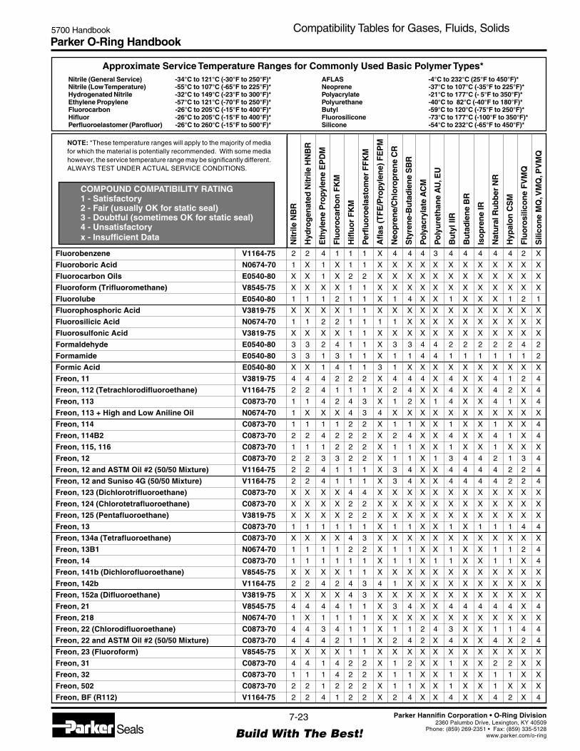
Parker O-Ring Handbook5700 Handbook Compatibility Tables for Gases, Fluids, Solids
NOTE: *These temperature ranges will apply to the majority of mediafor which the material is potentially recommended. With some mediahowever, the service temperature range may be significantly different.ALWAYS TEST UNDER ACTUAL SERVICE CONDITIONS.
Nitrile (General Service) -34°C to 121°C (-30°F to 250°F)*Nitrile (Low Temperature) -55°C to 107°C (-65°F to 225°F)*Hydrogenated Nitrile -32°C to 149°C (-23°F to 300°F)*Ethylene Propylene -57°C to 121°C (-70°F to 250°F)*Fluorocarbon -26°C to 205°C (-15°F to 400°F)*Hifluor -26°C to 205°C (-15°F to 400°F)*Perfluoroelastomer (Parofluor) -26°C to 260°C (-15°F to 500°F)*
Approximate Service Temperature Ranges for Commonly Used Basic Polymer Types*
COMPOUND COMPATIBILITY RATING1 - Satisfactory2 - Fair (usually OK for static seal)3 - Doubtful (sometimes OK for static seal)4 - Unsatisfactoryx - Insufficient Data
AFLAS -4°C to 232°C (25°F to 450°F)*Neoprene -37°C to 107°C (-35°F to 225°F)*Polyacrylate -21°C to 177°C (- 5°F to 350°F)*Polyurethane -40°C to 82°C (-40°F to 180°F)*Butyl -59°C to 120°C (-75°F to 250°F)*Fluorosilicone -73°C to 177°C (-100°F to 350°F)*Silicone -54°C to 232°C (-65°F to 450°F)*
Nitr
ile N
BR
Hyd
rog
enat
ed N
itrile
HN
BR
Eth
ylen
e P
ropy
len
e E
PD
M
Flu
oro
carb
on
FK
M
Hifl
uo
r F
KM
Per
fluo
roel
asto
mer
FF
KM
Afla
s (T
FE
/Pro
pyle
ne)
FE
PM
Neo
pre
ne/
Ch
loro
pre
ne
CR
Sty
ren
e-B
uta
die
ne
SB
R
Po
lyac
ryla
te A
CM
Po
lyu
reth
ane
AU
, EU
Bu
tyl I
IR
Bu
tad
ien
e B
R
Iso
pre
ne
IR
Nat
ura
l Ru
bb
er N
R
Hyp
alo
n C
SM
Flu
oro
silic
on
e F
VM
Q
Sili
con
e M
Q, V
MQ
, PV
MQ
7-23
Build With The Best!SealsParker Hannifin Corporation • O-Ring Division
2360 Palumbo Drive, Lexington, KY 40509Phone: (859) 269-2351 • Fax: (859) 335-5128
www.parker.com/o-ring
Fluorobenzene V1164-75 2 2 4 1 1 1 X 4 4 4 3 4 4 4 4 4 2 X
Fluoroboric Acid N0674-70 1 X 1 X 1 1 X X X X X X X X X X X X
Fluorocarbon Oils E0540-80 X X 1 X 2 2 X X X X X X X X X X X X
Fluoroform (Trifluoromethane) V8545-75 X X X X 1 1 X X X X X X X X X X X X
Fluorolube E0540-80 1 1 1 2 1 1 X 1 4 X X 1 X X X 1 2 1
Fluorophosphoric Acid V3819-75 X X X X 1 1 X X X X X X X X X X X X
Fluorosilicic Acid N0674-70 1 1 2 2 1 1 1 1 X X X X X X X X X X
Fluorosulfonic Acid V3819-75 X X X X 1 1 X X X X X X X X X X X X
Formaldehyde E0540-80 3 3 2 4 1 1 X 3 3 4 4 2 2 2 2 2 4 2
Formamide E0540-80 3 3 1 3 1 1 X 1 1 4 4 1 1 1 1 1 1 2
Formic Acid E0540-80 X X 1 4 1 1 3 1 X X X X X X X X X X
Freon, 11 V3819-75 4 4 4 2 2 2 X 4 4 4 X 4 X X 4 1 2 4
Freon, 112 (Tetrachlorodifluoroethane) V1164-75 2 2 4 1 1 1 X 2 4 X X 4 X X 4 2 X 4
Freon, 113 C0873-70 1 1 4 2 4 3 X 1 2 X 1 4 X X 4 1 X 4
Freon, 113 + High and Low Aniline Oil N0674-70 1 X X X 4 3 4 X X X X X X X X X X X
Freon, 114 C0873-70 1 1 1 1 2 2 X 1 1 X X 1 X X 1 X X 4
Freon, 114B2 C0873-70 2 2 4 2 2 2 X 2 4 X X 4 X X 4 1 X 4
Freon, 115, 116 C0873-70 1 1 1 2 2 2 X 1 1 X X 1 X X 1 X X X
Freon, 12 C0873-70 2 2 3 3 2 2 X 1 1 X 1 3 4 4 2 1 3 4
Freon, 12 and ASTM Oil #2 (50/50 Mixture) V1164-75 2 2 4 1 1 1 X 3 4 X X 4 4 4 4 2 2 4
Freon, 12 and Suniso 4G (50/50 Mixture) V1164-75 2 2 4 1 1 1 X 3 4 X X 4 4 4 4 2 2 4
Freon, 123 (Dichlorotrifluoroethane) C0873-70 X X X X 4 4 X X X X X X X X X X X X
Freon, 124 (Chlorotetrafluoroethane) C0873-70 X X X X 2 2 X X X X X X X X X X X X
Freon, 125 (Pentafluoroethane) V3819-75 X X X X 2 2 X X X X X X X X X X X X
Freon, 13 C0873-70 1 1 1 1 1 1 X 1 1 X X 1 X 1 1 1 4 4
Freon, 134a (Tetrafluoroethane) C0873-70 X X X X 4 3 X X X X X X X X X X X X
Freon, 13B1 N0674-70 1 1 1 1 2 2 X 1 1 X X 1 X X 1 1 2 4
Freon, 14 C0873-70 1 1 1 1 1 1 X 1 1 X 1 1 X X 1 1 X 4
Freon, 141b (Dichlorofluoroethane) V8545-75 X X X X 1 1 X X X X X X X X X X X X
Freon, 142b V1164-75 2 2 4 2 4 3 4 1 X X X X X X X X X X
Freon, 152a (Difluoroethane) V3819-75 X X X X 4 3 X X X X X X X X X X X X
Freon, 21 V8545-75 4 4 4 4 1 1 X 3 4 X X 4 4 4 4 4 X 4
Freon, 218 N0674-70 1 X 1 1 1 1 X X X X X X X X X X X X
Freon, 22 (Chlorodifluoroethane) C0873-70 4 4 3 4 1 1 X 1 1 2 4 3 X X 1 1 4 4
Freon, 22 and ASTM Oil #2 (50/50 Mixture) C0873-70 4 4 4 2 1 1 X 2 4 2 X 4 X X 4 X 2 4
Freon, 23 (Fluoroform) V8545-75 X X X X 1 1 X X X X X X X X X X X X
Freon, 31 C0873-70 4 4 1 4 2 2 X 1 2 X X 1 X X 2 2 X X
Freon, 32 C0873-70 1 1 1 4 2 2 X 1 1 X X 1 X X 1 1 X X
Freon, 502 C0873-70 2 2 1 2 2 2 X 1 1 X X 1 X X 1 X X X
Freon, BF (R112) V1164-75 2 2 4 1 2 2 X 2 4 X X 4 X X 4 2 X 4

Parker O-Ring Handbook5700 Handbook Compatibility Tables for Gases, Fluids, Solids
NOTE: *These temperature ranges will apply to the majority of mediafor which the material is potentially recommended. With some mediahowever, the service temperature range may be significantly different.ALWAYS TEST UNDER ACTUAL SERVICE CONDITIONS.
Nitrile (General Service) -34°C to 121°C (-30°F to 250°F)*Nitrile (Low Temperature) -55°C to 107°C (-65°F to 225°F)*Hydrogenated Nitrile -32°C to 149°C (-23°F to 300°F)*Ethylene Propylene -57°C to 121°C (-70°F to 250°F)*Fluorocarbon -26°C to 205°C (-15°F to 400°F)*Hifluor -26°C to 205°C (-15°F to 400°F)*Perfluoroelastomer (Parofluor) -26°C to 260°C (-15°F to 500°F)*
Approximate Service Temperature Ranges for Commonly Used Basic Polymer Types*
COMPOUND COMPATIBILITY RATING1 - Satisfactory2 - Fair (usually OK for static seal)3 - Doubtful (sometimes OK for static seal)4 - Unsatisfactoryx - Insufficient Data
AFLAS -4°C to 232°C (25°F to 450°F)*Neoprene -37°C to 107°C (-35°F to 225°F)*Polyacrylate -21°C to 177°C (- 5°F to 350°F)*Polyurethane -40°C to 82°C (-40°F to 180°F)*Butyl -59°C to 120°C (-75°F to 250°F)*Fluorosilicone -73°C to 177°C (-100°F to 350°F)*Silicone -54°C to 232°C (-65°F to 450°F)*
Nitr
ile N
BR
Hyd
rog
enat
ed N
itrile
HN
BR
Eth
ylen
e P
ropy
len
e E
PD
M
Flu
oro
carb
on
FK
M
Hifl
uo
r F
KM
Per
fluo
roel
asto
mer
FF
KM
Afla
s (T
FE
/Pro
pyle
ne)
FE
PM
Neo
pre
ne/
Ch
loro
pre
ne
CR
Sty
ren
e-B
uta
die
ne
SB
R
Po
lyac
ryla
te A
CM
Po
lyu
reth
ane
AU
, EU
Bu
tyl I
IR
Bu
tad
ien
e B
R
Iso
pre
ne
IR
Nat
ura
l Ru
bb
er N
R
Hyp
alo
n C
SM
Flu
oro
silic
on
e F
VM
Q
Sili
con
e M
Q, V
MQ
, PV
MQ
7-24
Build With The Best!SealsParker Hannifin Corporation • O-Ring Division
2360 Palumbo Drive, Lexington, KY 40509Phone: (859) 269-2351 • Fax: (859) 335-5128
www.parker.com/o-ring
Freon, C316 N0674-70 1 X 1 1 2 2 X X X X X X X X X X X X
Freon, C318 C0873-70 1 1 1 2 2 2 X 1 1 X X 1 X X 1 1 X X
Freon, K-142b C0873-70 1 1 1 4 4 4 X 1 1 X X 1 X X 2 1 X X
Freon, K-152a C0873-70 1 1 1 4 4 4 X 1 1 X X 1 X X 1 4 X X
Freon, MF (R11) N0674-70 2 2 4 2 2 2 X 4 4 X 3 4 X X 4 1 X 4
Freon, PCA (R113) N0674-70 1 1 4 2 1 1 X 1 2 X 1 4 X X 4 1 X 4
Freon, TA N0674-70 1 X 2 3 2 2 X X X X X X X X X X X X
Freon, TC N0674-70 1 X 2 1 2 2 X X X X X X X X X X X X
Freon, TF (R113) N0674-70 1 1 4 2 2 2 X 1 2 X 1 4 X X 4 1 X 4
Freon, TMC V1164-75 2 X 3 1 2 2 X X X X X X X X X X X X
Freon, T-P35 N0674-70 1 X 1 1 2 2 X X X X X X X X X X X X
Freon, T-WD602 V1164-75 2 X 2 1 2 2 X X X X X X X X X X X X
Fuel Oil, #6 V1164-75 2 2 4 1 1 1 X 4 4 1 2 4 4 4 4 4 1 1
Fuel Oil, 1, and 2 N0674-70 1 1 4 1 1 1 X 2 4 1 2 4 4 4 4 3 1 4
Fuel Oil, Acidic N0674-70 1 1 4 1 1 1 X 2 4 1 2 4 4 4 4 4 1 1
Fumaric Acid N0674-70 1 1 2 1 1 1 X 2 2 4 X 4 2 1 3 2 1 2
Fuming Sulphuric Acid (20/25% Oleum) V1164-75 4 4 4 1 1 1 X 4 4 4 4 4 4 4 4 4 X 4
Furaldehyde E0540-80 4 4 2 4 2 2 4 4 X X X X X X X X X X
Furan (Furfuran) V1164-75 4 4 3 1 1 1 X 4 4 4 X 4 4 4 4 4 X X
Furfural (Furfuraldehyde) E0540-80 4 4 2 4 1 1 X 4 4 4 3 2 4 4 4 3 X 4
Furfuraldehyde E0540-80 4 4 2 4 1 1 X 4 4 4 3 2 4 4 4 3 X 4
Furfuryl Alcohol E0540-80 4 4 2 X 1 1 X 4 4 4 4 2 4 4 4 4 4 4
Furoic Acid V3819-75 X X X X 1 1 X X X X X X X X X X X X
Furyl Carbinol E0540-80 4 4 2 X X X X 4 4 4 4 2 4 4 4 4 4 4
Fyrquel 150 220 300 550 E0540-80 4 4 1 1 1 1 X 4 4 4 4 1 4 4 4 4 2 1
Fyrquel 90, 100, 500 E0540-80 4 4 1 1 1 1 1 X X X X X X X X X X X
Fyrquel A60 V3819-75 4 4 2 4 1 1 2 4 X X X X X X X X X X
— G —
Gallic Acid V1164-75 2 2 2 1 1 1 X 2 2 4 4 2 X 1 1 2 1 X
Gasoline N0497-70 1 1 4 1 1 1 X 4 4 4 2 4 4 4 4 4 1 4
Gelatin N0674-70 1 1 1 1 1 1 X 1 1 4 4 1 1 1 1 1 1 1
Germane (Germanium Tetrahydride) V3819-75 X X X X 1 1 X X X X X X X X X X X X
Girling Brake Fluid E0603-70 3 3 1 4 1 1 X 2 1 X X 2 X X X 2 4 X
Glauber’s Salt V1164-75 4 4 2 1 1 1 X 2 4 4 X 2 4 2 2 2 1 X
Gluconic Acid E0540-80 3 3 1 3 1 1 X 1 1 4 4 1 1 1 1 1 1 2
Glucose N0674-70 1 1 1 1 1 1 X 1 1 X 4 1 1 1 1 1 1 1
Glue V3819-75 X X X X 1 1 X X X X X X X X X X X X
Glutamic Acid E0540-80 3 3 1 3 1 1 X 1 1 4 4 1 1 1 1 1 1 2
Glycerine (Glycerol) N0674-70 1 1 1 1 1 1 X 1 1 4 4 1 1 1 1 1 1 1
Glycerol Dichlorohydrin E0540-80 3 3 1 3 1 1 X 1 1 4 4 1 1 1 1 1 1 2

Parker O-Ring Handbook5700 Handbook Compatibility Tables for Gases, Fluids, Solids
NOTE: *These temperature ranges will apply to the majority of mediafor which the material is potentially recommended. With some mediahowever, the service temperature range may be significantly different.ALWAYS TEST UNDER ACTUAL SERVICE CONDITIONS.
Nitrile (General Service) -34°C to 121°C (-30°F to 250°F)*Nitrile (Low Temperature) -55°C to 107°C (-65°F to 225°F)*Hydrogenated Nitrile -32°C to 149°C (-23°F to 300°F)*Ethylene Propylene -57°C to 121°C (-70°F to 250°F)*Fluorocarbon -26°C to 205°C (-15°F to 400°F)*Hifluor -26°C to 205°C (-15°F to 400°F)*Perfluoroelastomer (Parofluor) -26°C to 260°C (-15°F to 500°F)*
Approximate Service Temperature Ranges for Commonly Used Basic Polymer Types*
COMPOUND COMPATIBILITY RATING1 - Satisfactory2 - Fair (usually OK for static seal)3 - Doubtful (sometimes OK for static seal)4 - Unsatisfactoryx - Insufficient Data
AFLAS -4°C to 232°C (25°F to 450°F)*Neoprene -37°C to 107°C (-35°F to 225°F)*Polyacrylate -21°C to 177°C (- 5°F to 350°F)*Polyurethane -40°C to 82°C (-40°F to 180°F)*Butyl -59°C to 120°C (-75°F to 250°F)*Fluorosilicone -73°C to 177°C (-100°F to 350°F)*Silicone -54°C to 232°C (-65°F to 450°F)*
Nitr
ile N
BR
Hyd
rog
enat
ed N
itrile
HN
BR
Eth
ylen
e P
ropy
len
e E
PD
M
Flu
oro
carb
on
FK
M
Hifl
uo
r F
KM
Per
fluo
roel
asto
mer
FF
KM
Afla
s (T
FE
/Pro
pyle
ne)
FE
PM
Neo
pre
ne/
Ch
loro
pre
ne
CR
Sty
ren
e-B
uta
die
ne
SB
R
Po
lyac
ryla
te A
CM
Po
lyu
reth
ane
AU
, EU
Bu
tyl I
IR
Bu
tad
ien
e B
R
Iso
pre
ne
IR
Nat
ura
l Ru
bb
er N
R
Hyp
alo
n C
SM
Flu
oro
silic
on
e F
VM
Q
Sili
con
e M
Q, V
MQ
, PV
MQ
7-25
Build With The Best!SealsParker Hannifin Corporation • O-Ring Division
2360 Palumbo Drive, Lexington, KY 40509Phone: (859) 269-2351 • Fax: (859) 335-5128
www.parker.com/o-ring
Glycerol Monochlorohydrin E0540-80 3 3 1 3 1 1 X 1 1 4 4 1 1 1 1 1 1 2
Glycerol Triacetate E0540-80 3 3 1 3 1 1 X 1 1 4 4 1 1 1 1 1 1 2
Glycerophosphoric Acid E0540-80 3 3 1 3 1 1 X 1 1 4 4 1 1 1 1 1 1 2
Glyceryl Phosphate E0540-80 3 3 1 3 1 1 X 1 1 4 4 1 1 1 1 1 1 2
Glycidol E0540-80 3 3 1 3 1 1 X 1 1 4 4 1 1 1 1 1 1 2
Glycol Monoether V3819-75 X X X X 2 1 X X X X X X X X X X X X
Glycolic Acid E0540-80 3 3 1 3 1 1 X 1 1 4 4 1 1 1 1 1 1 2
Glycols E0540-80 1 1 1 1 1 1 X 1 1 4 4 1 1 1 1 1 1 1
Glycoxylic Acid E0540-80 3 3 1 3 1 1 X 1 1 4 4 1 1 1 1 1 1 2
Grease Petroleum Base N0674-70 1 1 4 1 1 1 X 3 4 1 1 4 4 4 4 4 1 4
Green Sulfate Liquor E0540-80 2 2 1 1 1 1 X 2 2 4 4 1 2 2 2 2 2 X
Gulf Endurance Oils N0674-70 1 1 4 1 1 1 X 2 4 1 1 4 4 4 4 4 1 4
Gulf FR Fluids (Emulsion) N0674-70 1 1 4 1 1 1 X 2 4 1 1 4 4 4 4 4 1 4
Gulf FR G-Fluids E0540-80 1 1 1 1 1 1 X 1 1 4 2 1 1 1 1 1 1 1
Gulf FR P-Fluids E0540-80 4 4 2 2 1 1 X 4 4 4 4 2 4 4 4 4 2 1
Gulf Harmony Oils N0674-70 1 1 4 1 1 1 X 2 4 1 1 4 4 4 4 4 1 4
Gulf High Temperature Grease N0674-70 1 1 4 1 1 1 X 2 4 1 1 4 4 4 4 4 1 4
Gulf Legion Oils N0674-70 1 1 4 1 1 1 X 2 4 1 1 4 4 4 4 4 1 4
Gulf Paramount Oils N0674-70 1 1 4 1 1 1 X 2 4 1 2 4 4 4 4 4 1 4
Gulf Security Oils N0674-70 1 1 4 1 1 1 X 2 4 1 2 4 4 4 4 4 1 4
Gulfcrown Grease N0674-70 1 1 4 1 1 1 X 2 4 1 1 4 4 4 4 4 1 4
— H —
Halothane V1164-75 4 4 4 1 1 1 X 4 4 4 4 4 4 4 4 4 2 4
Halowax Oil V1164-75 4 4 4 1 1 1 X 4 4 X X 4 4 4 4 4 1 4
Hannifin Lube A N0674-70 1 1 4 1 1 1 X 1 2 1 1 4 4 4 4 1 1 2
Heavy Water N0674-70 1 1 1 X 1 1 X 2 1 4 4 1 1 1 1 1 1 1
HEF-2 (High Energy Fuel) V1164-75 2 2 4 1 1 1 X 4 4 4 4 4 4 4 4 4 2 4
Helium B0612-70 1 1 1 1 1 1 X 1 1 1 1 1 1 1 1 1 1 1
Heptachlor V1164-75 2 2 4 1 1 1 X 4 4 4 3 4 4 4 4 4 2 X
Heptachlorobutene V1164-75 2 2 4 1 1 1 X 4 4 4 3 4 4 4 4 4 2 X
Heptaldehyde (Heptanal) N0674-70 1 1 4 1 1 1 X 2 4 1 1 4 4 4 4 2 1 2
Heptane or n-Heptane N0674-70 1 1 4 1 1 1 X 2 4 1 2 4 4 4 4 2 3 4
Heptanoic Acid N0674-70 1 1 4 1 1 1 X 2 4 1 1 4 4 4 4 2 1 2
Hexachloroacetone E0540-80 3 3 1 3 1 1 X 1 1 4 4 1 1 1 1 1 1 2
Hexachlorobutadiene V1164-75 2 2 4 1 1 1 X 4 4 4 3 4 4 4 4 4 2 X
Hexachlorobutene V1164-75 2 2 4 1 1 1 X 4 4 4 3 4 4 4 4 4 2 X
Hexachloroethane V1164-75 2 2 4 1 1 1 X 4 4 4 3 4 4 4 4 4 2 X
Hexaethyl Tetraphosphate V3819-75 X X X X 1 1 X X X X X X X X X X X X
Hexafluoroethane (F-116) V3819-75 X X X X 2 2 X X X X X X X X X X X X
Hexafluoroxylene V3819-75 X X X X 1 1 X X X X X X X X X X X X
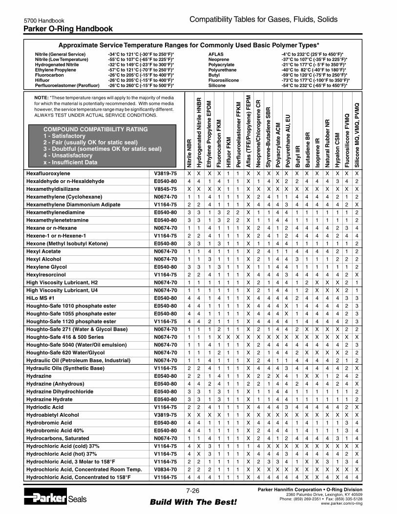
Parker O-Ring Handbook5700 Handbook Compatibility Tables for Gases, Fluids, Solids
NOTE: *These temperature ranges will apply to the majority of mediafor which the material is potentially recommended. With some mediahowever, the service temperature range may be significantly different.ALWAYS TEST UNDER ACTUAL SERVICE CONDITIONS.
Nitrile (General Service) -34°C to 121°C (-30°F to 250°F)*Nitrile (Low Temperature) -55°C to 107°C (-65°F to 225°F)*Hydrogenated Nitrile -32°C to 149°C (-23°F to 300°F)*Ethylene Propylene -57°C to 121°C (-70°F to 250°F)*Fluorocarbon -26°C to 205°C (-15°F to 400°F)*Hifluor -26°C to 205°C (-15°F to 400°F)*Perfluoroelastomer (Parofluor) -26°C to 260°C (-15°F to 500°F)*
Approximate Service Temperature Ranges for Commonly Used Basic Polymer Types*
COMPOUND COMPATIBILITY RATING1 - Satisfactory2 - Fair (usually OK for static seal)3 - Doubtful (sometimes OK for static seal)4 - Unsatisfactoryx - Insufficient Data
AFLAS -4°C to 232°C (25°F to 450°F)*Neoprene -37°C to 107°C (-35°F to 225°F)*Polyacrylate -21°C to 177°C (- 5°F to 350°F)*Polyurethane -40°C to 82°C (-40°F to 180°F)*Butyl -59°C to 120°C (-75°F to 250°F)*Fluorosilicone -73°C to 177°C (-100°F to 350°F)*Silicone -54°C to 232°C (-65°F to 450°F)*
Nitr
ile N
BR
Hyd
rog
enat
ed N
itrile
HN
BR
Eth
ylen
e P
ropy
len
e E
PD
M
Flu
oro
carb
on
FK
M
Hifl
uo
r F
KM
Per
fluo
roel
asto
mer
FF
KM
Afla
s (T
FE
/Pro
pyle
ne)
FE
PM
Neo
pre
ne/
Ch
loro
pre
ne
CR
Sty
ren
e-B
uta
die
ne
SB
R
Po
lyac
ryla
te A
CM
Po
lyu
reth
ane
AU
, EU
Bu
tyl I
IR
Bu
tad
ien
e B
R
Iso
pre
ne
IR
Nat
ura
l Ru
bb
er N
R
Hyp
alo
n C
SM
Flu
oro
silic
on
e F
VM
Q
Sili
con
e M
Q, V
MQ
, PV
MQ
7-26
Build With The Best!SealsParker Hannifin Corporation • O-Ring Division
2360 Palumbo Drive, Lexington, KY 40509Phone: (859) 269-2351 • Fax: (859) 335-5128
www.parker.com/o-ring
Hexafluoroxylene V3819-75 X X X X 1 1 X X X X X X X X X X X X
Hexaldehyde or n-Hexaldehyde E0540-80 4 4 1 4 1 1 X 1 4 X 2 2 4 4 4 3 4 2
Hexamethyldisilizane V8545-75 X X X X 1 1 X X X X X X X X X X X X
Hexamethylene (Cyclohexane) N0674-70 1 1 4 1 1 1 X 2 4 1 1 4 4 4 4 2 1 2
Hexamethylene Diammonium Adipate V1164-75 2 2 4 1 1 1 X 4 4 4 3 4 4 4 4 4 2 X
Hexamethylenediamine E0540-80 3 3 1 3 2 2 X 1 1 4 4 1 1 1 1 1 1 2
Hexamethylenetetramine E0540-80 3 3 1 3 2 2 X 1 1 4 4 1 1 1 1 1 1 2
Hexane or n-Hexane N0674-70 1 1 4 1 1 1 X 2 4 1 2 4 4 4 4 2 3 4
Hexene-1 or n-Hexene-1 V1164-75 2 2 4 1 1 1 X 2 4 1 2 4 4 4 4 2 4 4
Hexone (Methyl Isobutyl Ketone) E0540-80 3 3 1 3 1 1 X 1 1 4 4 1 1 1 1 1 1 2
Hexyl Acetate N0674-70 1 1 4 1 1 1 X 2 4 1 1 4 4 4 4 2 1 2
Hexyl Alcohol N0674-70 1 1 3 1 1 1 X 2 1 4 4 3 1 1 1 2 2 2
Hexylene Glycol E0540-80 3 3 1 3 1 1 X 1 1 4 4 1 1 1 1 1 1 2
Hexylresorcinol V1164-75 2 2 4 1 1 1 X 4 4 4 3 4 4 4 4 4 2 X
High Viscosity Lubricant, H2 N0674-70 1 1 1 1 1 1 X 2 1 4 4 1 2 X X X 2 1
High Viscosity Lubricant, U4 N0674-70 1 1 1 1 1 1 X 2 1 4 4 1 2 X X X 2 1
HiLo MS #1 E0540-80 4 4 1 4 1 1 X 4 4 4 4 2 4 4 4 4 3 3
Houghto-Safe 1010 phosphate ester E0540-80 4 4 1 1 1 1 X 4 4 4 X 1 4 4 4 4 2 3
Houghto-Safe 1055 phosphate ester E0540-80 4 4 1 1 1 1 X 4 4 4 X 1 4 4 4 4 2 3
Houghto-Safe 1120 phosphate ester V1164-75 4 4 2 1 1 1 X 4 4 4 4 1 4 4 4 4 2 3
Houghto-Safe 271 (Water & Glycol Base) N0674-70 1 1 1 2 1 1 X 2 1 4 4 2 X X X X 2 2
Houghto-Safe 416 & 500 Series N0674-70 1 1 1 X X X X X X X X X X X X X X X
Houghto-Safe 5040 (Water/Oil emulsion) N0674-70 1 1 4 1 1 1 X 2 4 4 4 4 4 4 4 4 2 3
Houghto-Safe 620 Water/Glycol N0674-70 1 1 1 2 1 1 X 2 1 4 4 2 X X X X 2 2
Hydraulic Oil (Petroleum Base, Industrial) N0674-70 1 1 4 1 1 1 X 2 4 1 1 4 4 4 4 2 1 2
Hydraulic Oils (Synthetic Base) V1164-75 2 2 4 1 1 1 X 4 4 4 3 4 4 4 4 4 2 X
Hydrazine E0540-80 2 2 1 4 1 1 X 2 2 X 4 1 X X 1 2 4 2
Hydrazine (Anhydrous) E0540-80 4 4 2 4 1 1 2 2 1 4 4 2 4 4 4 2 4 X
Hydrazine Dihydrochloride E0540-80 3 3 1 3 1 1 X 1 1 4 4 1 1 1 1 1 1 2
Hydrazine Hydrate E0540-80 3 3 1 3 1 1 X 1 1 4 4 1 1 1 1 1 1 2
Hydriodic Acid V1164-75 2 2 4 1 1 1 X 4 4 4 3 4 4 4 4 4 2 X
Hydroabietyl Alcohol V3819-75 X X X X 1 1 X X X X X X X X X X X X
Hydrobromic Acid E0540-80 4 4 1 1 1 1 X 4 4 4 4 1 4 1 1 1 3 4
Hydrobromic Acid 40% E0540-80 4 4 1 1 1 1 X 2 4 4 4 1 4 1 1 1 3 4
Hydrocarbons, Saturated N0674-70 1 1 4 1 1 1 X 2 4 1 2 4 4 4 4 3 1 4
Hydrochloric Acid (cold) 37% V1164-75 4 X 3 1 1 1 1 4 X X X X X X X X X X
Hydrochloric Acid (hot) 37% V1164-75 4 X 3 1 1 1 X 4 4 4 3 4 4 4 4 4 2 X
Hydrochloric Acid, 3 Molar to 158°F V1164-75 2 2 1 1 1 1 X 2 3 3 4 1 X X 3 1 3 4
Hydrochloric Acid, Concentrated Room Temp. V0834-70 2 2 2 1 1 1 X X X X X X X X X X X X
Hydrochloric Acid, Concentrated to 158°F V1164-75 4 4 4 1 1 1 X 4 4 4 4 4 X X 4 X 4 4
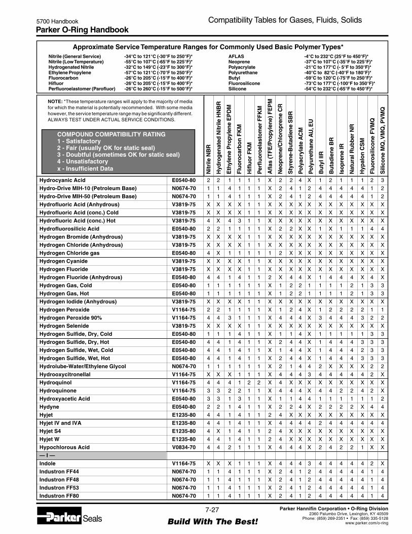
Parker O-Ring Handbook5700 Handbook Compatibility Tables for Gases, Fluids, Solids
NOTE: *These temperature ranges will apply to the majority of mediafor which the material is potentially recommended. With some mediahowever, the service temperature range may be significantly different.ALWAYS TEST UNDER ACTUAL SERVICE CONDITIONS.
Nitrile (General Service) -34°C to 121°C (-30°F to 250°F)*Nitrile (Low Temperature) -55°C to 107°C (-65°F to 225°F)*Hydrogenated Nitrile -32°C to 149°C (-23°F to 300°F)*Ethylene Propylene -57°C to 121°C (-70°F to 250°F)*Fluorocarbon -26°C to 205°C (-15°F to 400°F)*Hifluor -26°C to 205°C (-15°F to 400°F)*Perfluoroelastomer (Parofluor) -26°C to 260°C (-15°F to 500°F)*
Approximate Service Temperature Ranges for Commonly Used Basic Polymer Types*
COMPOUND COMPATIBILITY RATING1 - Satisfactory2 - Fair (usually OK for static seal)3 - Doubtful (sometimes OK for static seal)4 - Unsatisfactoryx - Insufficient Data
AFLAS -4°C to 232°C (25°F to 450°F)*Neoprene -37°C to 107°C (-35°F to 225°F)*Polyacrylate -21°C to 177°C (- 5°F to 350°F)*Polyurethane -40°C to 82°C (-40°F to 180°F)*Butyl -59°C to 120°C (-75°F to 250°F)*Fluorosilicone -73°C to 177°C (-100°F to 350°F)*Silicone -54°C to 232°C (-65°F to 450°F)*
Nitr
ile N
BR
Hyd
rog
enat
ed N
itrile
HN
BR
Eth
ylen
e P
ropy
len
e E
PD
M
Flu
oro
carb
on
FK
M
Hifl
uo
r F
KM
Per
fluo
roel
asto
mer
FF
KM
Afla
s (T
FE
/Pro
pyle
ne)
FE
PM
Neo
pre
ne/
Ch
loro
pre
ne
CR
Sty
ren
e-B
uta
die
ne
SB
R
Po
lyac
ryla
te A
CM
Po
lyu
reth
ane
AU
, EU
Bu
tyl I
IR
Bu
tad
ien
e B
R
Iso
pre
ne
IR
Nat
ura
l Ru
bb
er N
R
Hyp
alo
n C
SM
Flu
oro
silic
on
e F
VM
Q
Sili
con
e M
Q, V
MQ
, PV
MQ
7-27
Build With The Best!SealsParker Hannifin Corporation • O-Ring Division
2360 Palumbo Drive, Lexington, KY 40509Phone: (859) 269-2351 • Fax: (859) 335-5128
www.parker.com/o-ring
Hydrocyanic Acid E0540-80 2 2 1 1 1 1 X 2 2 4 X 1 2 1 1 1 2 3
Hydro-Drive MIH-10 (Petroleum Base) N0674-70 1 1 4 1 1 1 X 2 4 1 2 4 4 4 4 4 1 2
Hydro-Drive MIH-50 (Petroleum Base) N0674-70 1 1 4 1 1 1 X 2 4 1 2 4 4 4 4 4 1 2
Hydrofluoric Acid (Anhydrous) V3819-75 X X X X 1 1 X X X X X X X X X X X X
Hydrofluoric Acid (conc.) Cold V3819-75 X X X X 1 1 X X X X X X X X X X X X
Hydrofluoric Acid (conc.) Hot V3819-75 4 X 4 3 1 1 X X X X X X X X X X X X
Hydrofluorosilicic Acid E0540-80 2 2 1 1 1 1 X 2 2 X X 1 X 1 1 1 4 4
Hydrogen Bromide (Anhydrous) V3819-75 X X X X 1 1 X X X X X X X X X X X X
Hydrogen Chloride (Anhydrous) V3819-75 X X X X 1 1 X X X X X X X X X X X X
Hydrogen Chloride gas E0540-80 4 X 1 1 1 1 1 2 X X X X X X X X X X
Hydrogen Cyanide V3819-75 X X X X 1 1 X X X X X X X X X X X X
Hydrogen Fluoride V3819-75 X X X X 1 1 X X X X X X X X X X X X
Hydrogen Fluoride (Anhydrous) E0540-80 4 4 1 4 1 1 2 X 4 4 X 1 4 4 4 X 4 X
Hydrogen Gas, Cold E0540-80 1 1 1 1 1 1 X 1 2 2 1 1 1 1 2 1 3 3
Hydrogen Gas, Hot E0540-80 1 1 1 1 1 1 X 1 2 2 1 1 1 1 2 1 3 3
Hydrogen Iodide (Anhydrous) V3819-75 X X X X 1 1 X X X X X X X X X X X X
Hydrogen Peroxide V1164-75 2 2 1 1 1 1 X 1 2 4 X 1 2 2 2 2 1 1
Hydrogen Peroxide 90% V1164-75 4 4 3 1 1 1 X 4 4 4 X 3 4 4 4 3 2 2
Hydrogen Selenide V3819-75 X X X X 1 1 X X X X X X X X X X X X
Hydrogen Sulfide, Dry, Cold E0540-80 1 1 1 4 1 1 X 1 1 4 X 1 1 1 1 1 3 3
Hydrogen Sulfide, Dry, Hot E0540-80 4 4 1 4 1 1 X 2 4 4 X 1 4 4 4 3 3 3
Hydrogen Sulfide, Wet, Cold E0540-80 4 4 1 4 1 1 X 1 4 4 X 1 4 4 4 2 3 3
Hydrogen Sulfide, Wet, Hot E0540-80 4 4 1 4 1 1 X 2 4 4 X 1 4 4 4 3 3 3
Hydrolube-Water/Ethylene Glycol N0674-70 1 1 1 1 1 1 X 2 1 4 4 2 X X X X 2 2
Hydrooxycitronellal V1164-75 X X X 1 1 1 X 4 4 4 3 4 4 4 4 4 2 X
Hydroquinol V1164-75 4 4 4 1 2 2 X 4 X X X X X X X X X X
Hydroquinone V1164-75 3 3 2 2 1 1 X 4 4 4 X 4 4 2 2 4 2 X
Hydroxyacetic Acid E0540-80 3 3 1 3 1 1 X 1 1 4 4 1 1 1 1 1 1 2
Hydyne E0540-80 2 2 1 4 1 1 X 2 2 4 X 2 2 2 2 X 4 4
Hyjet E1235-80 4 4 1 4 1 1 2 4 X X X X X X X X X X
Hyjet IV and IVA E1235-80 4 4 1 4 1 1 X 4 4 4 4 2 4 4 4 4 4 4
Hyjet S4 E1235-80 4 X 1 4 1 1 2 4 X X X X X X X X X X
Hyjet W E1235-80 4 4 1 4 1 1 2 4 X X X X X X X X X X
Hypochlorous Acid V0834-70 4 4 2 1 1 1 X 4 4 4 X 2 4 2 2 1 X X
— I —
Indole V1164-75 X X X 1 1 1 X 4 4 4 3 4 4 4 4 4 2 X
Industron FF44 N0674-70 1 1 4 1 1 1 X 2 4 1 2 4 4 4 4 4 1 4
Industron FF48 N0674-70 1 1 4 1 1 1 X 2 4 1 2 4 4 4 4 4 1 4
Industron FF53 N0674-70 1 1 4 1 1 1 X 2 4 1 2 4 4 4 4 4 1 4
Industron FF80 N0674-70 1 1 4 1 1 1 X 2 4 1 2 4 4 4 4 4 1 4
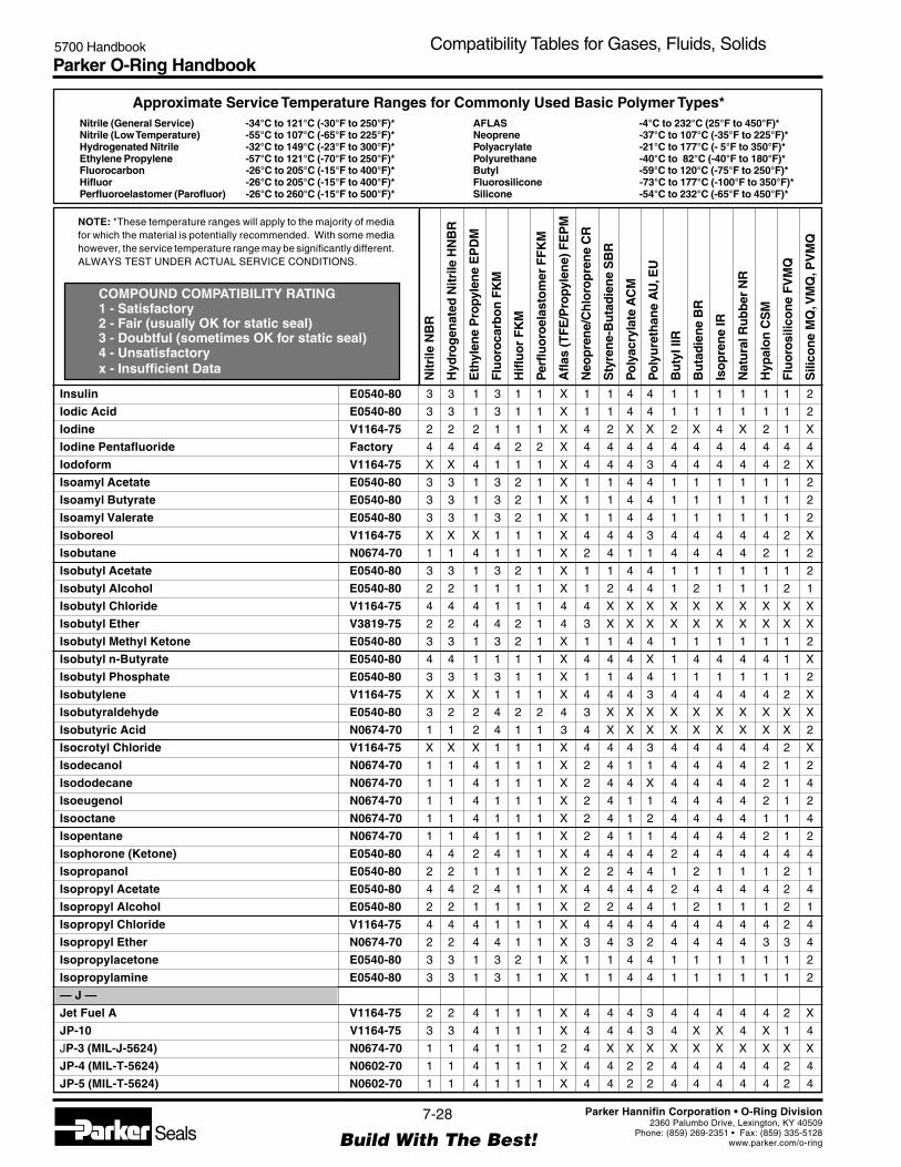
Parker O-Ring Handbook5700 Handbook Compatibility Tables for Gases, Fluids, Solids
NOTE: *These temperature ranges will apply to the majority of mediafor which the material is potentially recommended. With some mediahowever, the service temperature range may be significantly different.ALWAYS TEST UNDER ACTUAL SERVICE CONDITIONS.
Nitrile (General Service) -34°C to 121°C (-30°F to 250°F)*Nitrile (Low Temperature) -55°C to 107°C (-65°F to 225°F)*Hydrogenated Nitrile -32°C to 149°C (-23°F to 300°F)*Ethylene Propylene -57°C to 121°C (-70°F to 250°F)*Fluorocarbon -26°C to 205°C (-15°F to 400°F)*Hifluor -26°C to 205°C (-15°F to 400°F)*Perfluoroelastomer (Parofluor) -26°C to 260°C (-15°F to 500°F)*
Approximate Service Temperature Ranges for Commonly Used Basic Polymer Types*
COMPOUND COMPATIBILITY RATING1 - Satisfactory2 - Fair (usually OK for static seal)3 - Doubtful (sometimes OK for static seal)4 - Unsatisfactoryx - Insufficient Data
AFLAS -4°C to 232°C (25°F to 450°F)*Neoprene -37°C to 107°C (-35°F to 225°F)*Polyacrylate -21°C to 177°C (- 5°F to 350°F)*Polyurethane -40°C to 82°C (-40°F to 180°F)*Butyl -59°C to 120°C (-75°F to 250°F)*Fluorosilicone -73°C to 177°C (-100°F to 350°F)*Silicone -54°C to 232°C (-65°F to 450°F)*
Nitr
ile N
BR
Hyd
rog
enat
ed N
itrile
HN
BR
Eth
ylen
e P
ropy
len
e E
PD
M
Flu
oro
carb
on
FK
M
Hifl
uo
r F
KM
Per
fluo
roel
asto
mer
FF
KM
Afla
s (T
FE
/Pro
pyle
ne)
FE
PM
Neo
pre
ne/
Ch
loro
pre
ne
CR
Sty
ren
e-B
uta
die
ne
SB
R
Po
lyac
ryla
te A
CM
Po
lyu
reth
ane
AU
, EU
Bu
tyl I
IR
Bu
tad
ien
e B
R
Iso
pre
ne
IR
Nat
ura
l Ru
bb
er N
R
Hyp
alo
n C
SM
Flu
oro
silic
on
e F
VM
Q
Sili
con
e M
Q, V
MQ
, PV
MQ
7-28
Build With The Best!SealsParker Hannifin Corporation • O-Ring Division
2360 Palumbo Drive, Lexington, KY 40509Phone: (859) 269-2351 • Fax: (859) 335-5128
www.parker.com/o-ring
Insulin E0540-80 3 3 1 3 1 1 X 1 1 4 4 1 1 1 1 1 1 2
Iodic Acid E0540-80 3 3 1 3 1 1 X 1 1 4 4 1 1 1 1 1 1 2
Iodine V1164-75 2 2 2 1 1 1 X 4 2 X X 2 X 4 X 2 1 X
Iodine Pentafluoride Factory 4 4 4 4 2 2 X 4 4 4 4 4 4 4 4 4 4 4
Iodoform V1164-75 X X 4 1 1 1 X 4 4 4 3 4 4 4 4 4 2 X
Isoamyl Acetate E0540-80 3 3 1 3 2 1 X 1 1 4 4 1 1 1 1 1 1 2
Isoamyl Butyrate E0540-80 3 3 1 3 2 1 X 1 1 4 4 1 1 1 1 1 1 2
Isoamyl Valerate E0540-80 3 3 1 3 2 1 X 1 1 4 4 1 1 1 1 1 1 2
Isoboreol V1164-75 X X X 1 1 1 X 4 4 4 3 4 4 4 4 4 2 X
Isobutane N0674-70 1 1 4 1 1 1 X 2 4 1 1 4 4 4 4 2 1 2
Isobutyl Acetate E0540-80 3 3 1 3 2 1 X 1 1 4 4 1 1 1 1 1 1 2
Isobutyl Alcohol E0540-80 2 2 1 1 1 1 X 1 2 4 4 1 2 1 1 1 2 1
Isobutyl Chloride V1164-75 4 4 4 1 1 1 4 4 X X X X X X X X X X
Isobutyl Ether V3819-75 2 2 4 4 2 1 4 3 X X X X X X X X X X
Isobutyl Methyl Ketone E0540-80 3 3 1 3 2 1 X 1 1 4 4 1 1 1 1 1 1 2
Isobutyl n-Butyrate E0540-80 4 4 1 1 1 1 X 4 4 4 X 1 4 4 4 4 1 X
Isobutyl Phosphate E0540-80 3 3 1 3 1 1 X 1 1 4 4 1 1 1 1 1 1 2
Isobutylene V1164-75 X X X 1 1 1 X 4 4 4 3 4 4 4 4 4 2 X
Isobutyraldehyde E0540-80 3 2 2 4 2 2 4 3 X X X X X X X X X X
Isobutyric Acid N0674-70 1 1 2 4 1 1 3 4 X X X X X X X X X 2
Isocrotyl Chloride V1164-75 X X X 1 1 1 X 4 4 4 3 4 4 4 4 4 2 X
Isodecanol N0674-70 1 1 4 1 1 1 X 2 4 1 1 4 4 4 4 2 1 2
Isododecane N0674-70 1 1 4 1 1 1 X 2 4 4 X 4 4 4 4 2 1 4
Isoeugenol N0674-70 1 1 4 1 1 1 X 2 4 1 1 4 4 4 4 2 1 2
Isooctane N0674-70 1 1 4 1 1 1 X 2 4 1 2 4 4 4 4 1 1 4
Isopentane N0674-70 1 1 4 1 1 1 X 2 4 1 1 4 4 4 4 2 1 2
Isophorone (Ketone) E0540-80 4 4 2 4 1 1 X 4 4 4 4 2 4 4 4 4 4 4
Isopropanol E0540-80 2 2 1 1 1 1 X 2 2 4 4 1 2 1 1 1 2 1
Isopropyl Acetate E0540-80 4 4 2 4 1 1 X 4 4 4 4 2 4 4 4 4 2 4
Isopropyl Alcohol E0540-80 2 2 1 1 1 1 X 2 2 4 4 1 2 1 1 1 2 1
Isopropyl Chloride V1164-75 4 4 4 1 1 1 X 4 4 4 4 4 4 4 4 4 2 4
Isopropyl Ether N0674-70 2 2 4 4 1 1 X 3 4 3 2 4 4 4 4 3 3 4
Isopropylacetone E0540-80 3 3 1 3 2 1 X 1 1 4 4 1 1 1 1 1 1 2
Isopropylamine E0540-80 3 3 1 3 1 1 X 1 1 4 4 1 1 1 1 1 1 2
— J —
Jet Fuel A V1164-75 2 2 4 1 1 1 X 4 4 4 3 4 4 4 4 4 2 X
JP-10 V1164-75 3 3 4 1 1 1 X 4 4 4 3 4 X X 4 X 1 4
JP-3 (MIL-J-5624) N0674-70 1 1 4 1 1 1 2 4 X X X X X X X X X X
JP-4 (MIL-T-5624) N0602-70 1 1 4 1 1 1 X 4 4 2 2 4 4 4 4 4 2 4
JP-5 (MIL-T-5624) N0602-70 1 1 4 1 1 1 X 4 4 2 2 4 4 4 4 4 2 4

Parker O-Ring Handbook5700 Handbook Compatibility Tables for Gases, Fluids, Solids
NOTE: *These temperature ranges will apply to the majority of mediafor which the material is potentially recommended. With some mediahowever, the service temperature range may be significantly different.ALWAYS TEST UNDER ACTUAL SERVICE CONDITIONS.
Nitrile (General Service) -34°C to 121°C (-30°F to 250°F)*Nitrile (Low Temperature) -55°C to 107°C (-65°F to 225°F)*Hydrogenated Nitrile -32°C to 149°C (-23°F to 300°F)*Ethylene Propylene -57°C to 121°C (-70°F to 250°F)*Fluorocarbon -26°C to 205°C (-15°F to 400°F)*Hifluor -26°C to 205°C (-15°F to 400°F)*Perfluoroelastomer (Parofluor) -26°C to 260°C (-15°F to 500°F)*
Approximate Service Temperature Ranges for Commonly Used Basic Polymer Types*
COMPOUND COMPATIBILITY RATING1 - Satisfactory2 - Fair (usually OK for static seal)3 - Doubtful (sometimes OK for static seal)4 - Unsatisfactoryx - Insufficient Data
AFLAS -4°C to 232°C (25°F to 450°F)*Neoprene -37°C to 107°C (-35°F to 225°F)*Polyacrylate -21°C to 177°C (- 5°F to 350°F)*Polyurethane -40°C to 82°C (-40°F to 180°F)*Butyl -59°C to 120°C (-75°F to 250°F)*Fluorosilicone -73°C to 177°C (-100°F to 350°F)*Silicone -54°C to 232°C (-65°F to 450°F)*
Nitr
ile N
BR
Hyd
rog
enat
ed N
itrile
HN
BR
Eth
ylen
e P
ropy
len
e E
PD
M
Flu
oro
carb
on
FK
M
Hifl
uo
r F
KM
Per
fluo
roel
asto
mer
FF
KM
Afla
s (T
FE
/Pro
pyle
ne)
FE
PM
Neo
pre
ne/
Ch
loro
pre
ne
CR
Sty
ren
e-B
uta
die
ne
SB
R
Po
lyac
ryla
te A
CM
Po
lyu
reth
ane
AU
, EU
Bu
tyl I
IR
Bu
tad
ien
e B
R
Iso
pre
ne
IR
Nat
ura
l Ru
bb
er N
R
Hyp
alo
n C
SM
Flu
oro
silic
on
e F
VM
Q
Sili
con
e M
Q, V
MQ
, PV
MQ
7-29
Build With The Best!SealsParker Hannifin Corporation • O-Ring Division
2360 Palumbo Drive, Lexington, KY 40509Phone: (859) 269-2351 • Fax: (859) 335-5128
www.parker.com/o-ring
JP-6 (MIL-J-25656) N0602-70 1 1 4 1 1 1 X 4 4 2 2 4 4 4 4 4 2 4
JP-8 (MIL-T-83133) N0602-70 1 1 4 1 1 1 X 3 4 1 1 4 X X 4 X 2 4
JP-9 (MIL-F-81912) V1164-75 3 3 4 1 1 1 X 4 4 4 3 4 X X 4 X 2 4
JP-9 -11 V1164-75 4 4 4 1 1 1 X 4 4 4 4 4 X X 4 X 2 4
JPX (MIL-F-25604) N0674-70 1 1 4 4 1 1 2 2 X X X X X X X X X X
— K —
Kel F Liquids E0540-80 1 1 1 2 1 1 X X 1 X X 1 X X X 1 2 1
Kerosene (Similar to RP-1 and JP-1) N0674-70 1 1 4 1 1 1 X 2 4 1 1 4 4 4 4 4 1 4
Keystone #87HX-Grease N0674-70 1 1 4 1 1 1 X 4 4 1 1 4 4 4 4 4 1 4
— L —
Lacquer Solvents V3819-75 4 4 4 4 1 1 X 4 4 4 4 4 4 4 4 4 4 4
Lacquers V3819-75 4 4 4 4 1 1 X 4 4 4 4 4 4 4 4 4 4 4
Lactams-Amino Acids E0540-80 4 4 2 4 1 1 X 2 4 X X 2 4 4 4 2 4 X
Lactic Acid, Cold N0674-70 1 1 1 1 1 1 X 1 1 4 X 1 1 1 1 1 1 1
Lactic Acid, Hot V1164-75 4 4 4 1 1 1 X 4 4 4 X 4 4 4 4 3 2 2
Lactones (Cyclic Esters) E0540-80 4 4 2 4 1 1 X 4 4 4 4 2 4 4 4 4 4 2
Lard Animal Fat N0674-70 1 1 2 1 1 1 X 2 4 1 1 2 4 4 4 4 1 2
Lauric Acid N0674-70 1 1 4 1 1 1 X 2 4 1 1 4 4 4 4 2 1 2
Lavender Oil V1164-75 2 2 4 1 1 1 1 4 X X X X X X X X X X
LB 135 N0674-70 1 1 1 1 1 1 1 1 X X X X X X X X X X
Lead (Molten) V3819-75 X X X X 1 1 X X X X X X X X X X X X
Lead Acetate E0540-80 2 2 1 4 1 1 X 2 4 4 4 1 4 1 1 4 4 4
Lead Arsenate E0540-80 3 3 1 3 1 1 X 1 1 4 4 1 1 1 1 1 1 2
Lead Azide V3819-75 X X X X 1 1 X X X X X X X X X X X X
Lead Bromide E0540-80 3 3 1 3 1 1 X 1 1 4 4 1 1 1 1 1 1 2
Lead Carbonate E0540-80 3 3 1 3 1 1 X 1 1 4 4 1 1 1 1 1 1 2
Lead Chloride E0540-80 3 3 1 3 1 1 X 1 1 4 4 1 1 1 1 1 1 2
Lead Chromate E0540-80 3 3 1 3 1 1 X 1 1 4 4 1 1 1 1 1 1 2
Lead Dioxide E0540-80 3 3 1 3 1 1 X 1 1 4 4 1 1 1 1 1 1 2
Lead Linoleate E0540-80 3 3 1 3 1 1 X 1 1 4 4 1 1 1 1 1 1 2
Lead Naphthenate V3819-75 X X X X 1 1 X X X X X X X X X X X X
Lead Nitrate N0674-70 1 1 1 X 1 1 X 1 1 X X 1 1 1 1 1 1 2
Lead Oxide E0540-80 3 3 1 3 1 1 X 1 1 4 4 1 1 1 1 1 1 2
Lead Sulfamate C0873-70 2 2 1 1 1 1 X 1 2 4 X 1 2 2 2 1 1 2
Lehigh X1169 N0674-70 1 1 4 1 1 1 X 2 4 1 1 4 4 4 4 2 1 4
Lehigh X1170 N0674-70 1 1 4 1 1 1 X 2 4 1 1 4 4 4 4 2 1 4
Light Grease N0674-70 1 1 4 1 1 1 1 4 X X X X X X X X X X
Ligroin (Petroleum Ether or Benzene) N0674-70 1 1 4 1 1 1 X 2 4 1 2 4 4 4 4 3 1 4
Lime Bleach N0674-70 1 1 1 1 1 1 1 1 X X X X X X X X X X
Lime Sulfur V1164-75 X X X 1 1 1 X 4 4 4 3 4 4 4 4 4 2 X

Parker O-Ring Handbook5700 Handbook Compatibility Tables for Gases, Fluids, Solids
NOTE: *These temperature ranges will apply to the majority of mediafor which the material is potentially recommended. With some mediahowever, the service temperature range may be significantly different.ALWAYS TEST UNDER ACTUAL SERVICE CONDITIONS.
Nitrile (General Service) -34°C to 121°C (-30°F to 250°F)*Nitrile (Low Temperature) -55°C to 107°C (-65°F to 225°F)*Hydrogenated Nitrile -32°C to 149°C (-23°F to 300°F)*Ethylene Propylene -57°C to 121°C (-70°F to 250°F)*Fluorocarbon -26°C to 205°C (-15°F to 400°F)*Hifluor -26°C to 205°C (-15°F to 400°F)*Perfluoroelastomer (Parofluor) -26°C to 260°C (-15°F to 500°F)*
Approximate Service Temperature Ranges for Commonly Used Basic Polymer Types*
COMPOUND COMPATIBILITY RATING1 - Satisfactory2 - Fair (usually OK for static seal)3 - Doubtful (sometimes OK for static seal)4 - Unsatisfactoryx - Insufficient Data
AFLAS -4°C to 232°C (25°F to 450°F)*Neoprene -37°C to 107°C (-35°F to 225°F)*Polyacrylate -21°C to 177°C (- 5°F to 350°F)*Polyurethane -40°C to 82°C (-40°F to 180°F)*Butyl -59°C to 120°C (-75°F to 250°F)*Fluorosilicone -73°C to 177°C (-100°F to 350°F)*Silicone -54°C to 232°C (-65°F to 450°F)*
Nitr
ile N
BR
Hyd
rog
enat
ed N
itrile
HN
BR
Eth
ylen
e P
ropy
len
e E
PD
M
Flu
oro
carb
on
FK
M
Hifl
uo
r F
KM
Per
fluo
roel
asto
mer
FF
KM
Afla
s (T
FE
/Pro
pyle
ne)
FE
PM
Neo
pre
ne/
Ch
loro
pre
ne
CR
Sty
ren
e-B
uta
die
ne
SB
R
Po
lyac
ryla
te A
CM
Po
lyu
reth
ane
AU
, EU
Bu
tyl I
IR
Bu
tad
ien
e B
R
Iso
pre
ne
IR
Nat
ura
l Ru
bb
er N
R
Hyp
alo
n C
SM
Flu
oro
silic
on
e F
VM
Q
Sili
con
e M
Q, V
MQ
, PV
MQ
7-30
Build With The Best!SealsParker Hannifin Corporation • O-Ring Division
2360 Palumbo Drive, Lexington, KY 40509Phone: (859) 269-2351 • Fax: (859) 335-5128
www.parker.com/o-ring
Lindol, Hydraulic Fluid (Phosphate ester type) E0540-80 4 4 1 2 1 1 X 4 4 4 4 1 4 4 4 4 3 3
Linoleic Acid S0604-70 2 2 4 2 1 1 X 2 4 X X 4 4 4 4 2 X 2
Linseed Oil N0674-70 1 1 3 1 1 1 X 3 4 1 2 3 4 4 4 2 1 1
Liquid Oxygen (LOX) Factory 4 4 4 4 3 2 X 4 4 4 4 4 4 4 4 4 4 4
Liquid Petroleum Gas (LPG) N0674-70 1 1 4 1 1 1 X 2 4 3 1 4 4 4 4 4 3 3
Liquimoly N0674-70 1 1 4 1 1 1 X 2 4 1 2 4 4 4 4 4 1 4
Lithium Bromide (Brine) E0540-80 3 3 1 3 1 1 X 1 1 4 4 1 1 1 1 1 1 2
Lithium Carbonate E0540-80 3 3 1 3 1 1 X 1 1 4 4 1 1 1 1 1 1 2
Lithium Chloride E0540-80 3 3 1 3 1 1 X 1 1 4 4 1 1 1 1 1 1 2
Lithium Citrate E0540-80 3 3 1 3 1 1 X 1 1 4 4 1 1 1 1 1 1 2
Lithium Hydroxide E0540-80 3 3 1 3 1 1 X 1 1 4 4 1 1 1 1 1 1 2
Lithium Hypochlorite E0540-80 3 3 1 3 1 1 X 1 1 4 4 1 1 1 1 1 1 2
Lithium Nitrate E0540-80 3 3 1 3 1 1 X 1 1 4 4 1 1 1 1 1 1 2
Lithium Nitrite E0540-80 3 3 1 3 1 1 X 1 1 4 4 1 1 1 1 1 1 2
Lithium Perchlorate E0540-80 3 3 1 3 1 1 X 1 1 4 4 1 1 1 1 1 1 2
Lithium Salicylate E0540-80 3 3 1 3 1 1 X 1 1 4 4 1 1 1 1 1 1 2
Lithopone E0540-80 3 3 1 3 1 1 X 1 1 4 4 1 1 1 1 1 1 2
Lubricating Oils (Crude & Refined) V1164-75 2 2 4 1 1 1 1 3 X X X X X X X X X X
Lubricating Oils (Synthetic base) V1164-75 X X X 1 1 1 X 4 4 4 3 4 4 4 4 4 2 X
Lubricating Oils, Di-ester V1164-75 2 2 4 1 1 1 X 3 4 2 X 4 4 4 4 X 2 4
Lubricating Oils, petroleum base N0674-70 1 1 4 1 1 1 X 2 4 1 2 4 4 4 4 4 1 4
Lubricating Oils, SAE 10, 20, 30, 40, 50 N0674-70 1 1 4 1 1 1 X 2 4 1 2 4 4 4 4 4 1 4
Lye Solutions E0540-80 2 2 1 2 1 1 X 2 2 4 4 1 2 2 1 1 2 2
—M —
Magnesium Chloride N0674-70 1 1 1 1 1 1 X 1 1 X 1 1 1 1 1 1 1 1
Magnesium Hydroxide E0540-80 2 2 1 1 1 1 X 2 2 4 4 1 2 2 2 1 X X
Magnesium Salts N0674-70 1 1 1 1 1 1 X 1 1 1 1 1 1 1 1 1 1 1
Magnesium Sulfite and Sulfate N0674-70 1 1 1 1 1 1 X 1 2 4 X 1 2 2 2 1 1 1
Magnesium Trisilicate V3819-75 X X X X 1 1 X X X X X X X X X X X X
Malathion V1164-75 2 2 4 1 1 1 X X 4 X X 4 4 4 4 X 2 4
Maleic Acid V1164-75 4 4 4 1 1 1 X 4 4 4 X 4 4 4 4 4 X X
Maleic Anhydride E0540-80 4 4 2 4 1 1 X 4 4 4 X 2 4 4 4 4 X X
Maleic Hydrazide E0540-80 3 3 1 3 1 1 X 1 1 4 4 1 1 1 1 1 1 2
Malic Acid V1164-75 1 1 2 1 1 1 X 2 2 4 X 4 2 1 3 2 1 2
Mandelic Acid E0540-80 3 3 1 3 1 1 X 1 1 4 4 1 1 1 1 1 1 2
Manganese Acetate E0540-80 3 3 1 3 1 1 X 1 1 4 4 1 1 1 1 1 1 2
Manganese Carbonate E0540-80 3 3 1 3 1 1 X 1 1 4 4 1 1 1 1 1 1 2
Manganese Chloride E0540-80 3 3 1 3 1 1 X 1 1 4 4 1 1 1 1 1 1 2
Manganese Dioxide E0540-80 3 3 1 3 1 1 X 1 1 4 4 1 1 1 1 1 1 2
Manganese Gluconate E0540-80 3 3 1 3 1 1 X 1 1 4 4 1 1 1 1 1 1 2
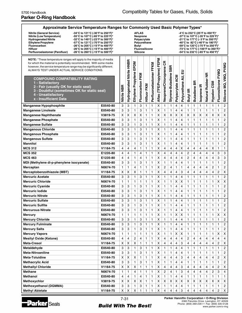
Parker O-Ring Handbook5700 Handbook Compatibility Tables for Gases, Fluids, Solids
NOTE: *These temperature ranges will apply to the majority of mediafor which the material is potentially recommended. With some mediahowever, the service temperature range may be significantly different.ALWAYS TEST UNDER ACTUAL SERVICE CONDITIONS.
Nitrile (General Service) -34°C to 121°C (-30°F to 250°F)*Nitrile (Low Temperature) -55°C to 107°C (-65°F to 225°F)*Hydrogenated Nitrile -32°C to 149°C (-23°F to 300°F)*Ethylene Propylene -57°C to 121°C (-70°F to 250°F)*Fluorocarbon -26°C to 205°C (-15°F to 400°F)*Hifluor -26°C to 205°C (-15°F to 400°F)*Perfluoroelastomer (Parofluor) -26°C to 260°C (-15°F to 500°F)*
Approximate Service Temperature Ranges for Commonly Used Basic Polymer Types*
COMPOUND COMPATIBILITY RATING1 - Satisfactory2 - Fair (usually OK for static seal)3 - Doubtful (sometimes OK for static seal)4 - Unsatisfactoryx - Insufficient Data
AFLAS -4°C to 232°C (25°F to 450°F)*Neoprene -37°C to 107°C (-35°F to 225°F)*Polyacrylate -21°C to 177°C (- 5°F to 350°F)*Polyurethane -40°C to 82°C (-40°F to 180°F)*Butyl -59°C to 120°C (-75°F to 250°F)*Fluorosilicone -73°C to 177°C (-100°F to 350°F)*Silicone -54°C to 232°C (-65°F to 450°F)*
Nitr
ile N
BR
Hyd
rog
enat
ed N
itrile
HN
BR
Eth
ylen
e P
ropy
len
e E
PD
M
Flu
oro
carb
on
FK
M
Hifl
uo
r F
KM
Per
fluo
roel
asto
mer
FF
KM
Afla
s (T
FE
/Pro
pyle
ne)
FE
PM
Neo
pre
ne/
Ch
loro
pre
ne
CR
Sty
ren
e-B
uta
die
ne
SB
R
Po
lyac
ryla
te A
CM
Po
lyu
reth
ane
AU
, EU
Bu
tyl I
IR
Bu
tad
ien
e B
R
Iso
pre
ne
IR
Nat
ura
l Ru
bb
er N
R
Hyp
alo
n C
SM
Flu
oro
silic
on
e F
VM
Q
Sili
con
e M
Q, V
MQ
, PV
MQ
7-31
Build With The Best!SealsParker Hannifin Corporation • O-Ring Division
2360 Palumbo Drive, Lexington, KY 40509Phone: (859) 269-2351 • Fax: (859) 335-5128
www.parker.com/o-ring
Manganese Hypophosphite E0540-80 3 3 1 3 1 1 X 1 1 4 4 1 1 1 1 1 1 2
Manganese Linoleate E0540-80 3 3 1 3 1 1 X 1 1 4 4 1 1 1 1 1 1 2
Manganese Naphthenate V3819-75 X X X X 1 1 X X X X X X X X X X X X
Manganese Phosphate E0540-80 3 3 1 3 1 1 X 1 1 4 4 1 1 1 1 1 1 2
Manganese Sulfate E0540-80 3 3 1 3 1 1 X 1 1 4 4 1 1 1 1 1 1 2
Manganous Chloride E0540-80 3 3 1 3 1 1 X 1 1 4 4 1 1 1 1 1 1 2
Manganous Phosphate E0540-80 3 3 1 3 1 1 X 1 1 4 4 1 1 1 1 1 1 2
Manganous Sulfate E0540-80 3 3 1 3 1 1 X 1 1 4 4 1 1 1 1 1 1 2
Mannitol E0540-80 3 3 1 3 1 1 X 1 1 4 4 1 1 1 1 1 1 2
MCS 312 V1164-75 4 4 4 1 1 1 X 4 4 4 X 4 4 4 4 X 1 1
MCS 352 E1235-80 4 4 1 4 1 1 X 4 4 4 4 2 4 4 4 4 3 3
MCS 463 E1235-80 4 4 1 4 1 1 X 4 4 4 4 2 4 4 4 4 3 3
MDI (Methylene di-p-phenylene isocyanate) E0540-80 3 3 1 3 1 1 X 1 1 4 4 1 1 1 1 1 1 2
Mercaptan N0674-70 1 1 4 1 1 1 X 2 4 1 1 4 4 4 4 2 1 2
Mercaptobenzothiazole (MBT) V1164-75 X X X 1 1 1 X 4 4 4 3 4 4 4 4 4 2 X
Mercuric Acetate E0540-80 3 3 1 3 1 1 X 1 1 4 4 1 1 1 1 1 1 2
Mercuric Chloride N0674-70 1 1 1 1 1 1 X 1 1 X X 1 1 1 1 1 X X
Mercuric Cyanide E0540-80 3 3 1 3 1 1 X 1 1 4 4 1 1 1 1 1 1 2
Mercuric Iodide E0540-80 3 3 1 3 1 1 X 1 1 4 4 1 1 1 1 1 1 2
Mercuric Nitrate E0540-80 3 3 1 3 1 1 X 1 1 4 4 1 1 1 1 1 1 2
Mercuric Sulfate E0540-80 3 3 1 3 1 1 X 1 1 4 4 1 1 1 1 1 1 2
Mercuric Sulfite E0540-80 3 3 1 3 1 1 X 1 1 4 4 1 1 1 1 1 1 2
Mercurous Nitrate E0540-80 3 3 1 3 1 1 X 1 1 4 4 1 1 1 1 1 1 2
Mercury N0674-70 1 1 1 1 1 1 X 1 1 X X 1 1 1 1 1 X X
Mercury Chloride E0540-80 3 3 1 3 1 1 X 1 1 4 4 1 1 1 1 1 1 2
Mercury Fulminate E0540-80 3 3 1 3 1 1 X 1 1 4 4 1 1 1 1 1 1 2
Mercury Salts E0540-80 3 3 1 3 1 1 X 1 1 4 4 1 1 1 1 1 1 2
Mercury Vapors N0674-70 1 1 1 1 1 1 X 1 1 X X 1 1 1 1 1 X X
Mesityl Oxide (Ketone) E0540-80 4 4 2 4 1 1 X 4 4 4 4 2 4 4 4 4 4 4
Meta-Cresol V1164-75 X X X 1 1 1 X 4 4 4 3 4 4 4 4 4 2 X
Metaldehyde E0540-80 3 3 1 3 1 1 X 1 1 4 4 1 1 1 1 1 1 2
Meta-Nitroaniline E0540-80 3 3 1 3 1 1 X 1 1 4 4 1 1 1 1 1 1 2
Meta-Toluidine V1164-75 X X X 1 1 1 X 4 4 4 3 4 4 4 4 4 2 X
Methacrylic Acid E0540-80 3 3 1 3 1 1 X 1 1 4 4 1 1 1 1 1 1 2
Methallyl Chloride V1164-75 X X X 1 1 1 X 4 4 4 3 4 4 4 4 4 2 X
Methane N0674-70 1 1 4 1 1 1 X 2 4 1 3 4 4 4 4 2 3 4
Methanol E0540-80 4 4 1 4 1 1 X 1 1 4 4 1 1 1 1 1 1 1
Methoxychlor V3819-75 X X X X 1 1 X X X X X X X X X X X X
Methoxyethanol (DGMMA) E0540-80 3 3 1 3 1 1 X 1 1 4 4 1 1 1 1 1 1 2
Methyl Abietate V1164-75 X X X 1 1 1 X 4 4 4 3 4 4 4 4 4 2 X

Parker O-Ring Handbook5700 Handbook Compatibility Tables for Gases, Fluids, Solids
NOTE: *These temperature ranges will apply to the majority of mediafor which the material is potentially recommended. With some mediahowever, the service temperature range may be significantly different.ALWAYS TEST UNDER ACTUAL SERVICE CONDITIONS.
Nitrile (General Service) -34°C to 121°C (-30°F to 250°F)*Nitrile (Low Temperature) -55°C to 107°C (-65°F to 225°F)*Hydrogenated Nitrile -32°C to 149°C (-23°F to 300°F)*Ethylene Propylene -57°C to 121°C (-70°F to 250°F)*Fluorocarbon -26°C to 205°C (-15°F to 400°F)*Hifluor -26°C to 205°C (-15°F to 400°F)*Perfluoroelastomer (Parofluor) -26°C to 260°C (-15°F to 500°F)*
Approximate Service Temperature Ranges for Commonly Used Basic Polymer Types*
COMPOUND COMPATIBILITY RATING1 - Satisfactory2 - Fair (usually OK for static seal)3 - Doubtful (sometimes OK for static seal)4 - Unsatisfactoryx - Insufficient Data
AFLAS -4°C to 232°C (25°F to 450°F)*Neoprene -37°C to 107°C (-35°F to 225°F)*Polyacrylate -21°C to 177°C (- 5°F to 350°F)*Polyurethane -40°C to 82°C (-40°F to 180°F)*Butyl -59°C to 120°C (-75°F to 250°F)*Fluorosilicone -73°C to 177°C (-100°F to 350°F)*Silicone -54°C to 232°C (-65°F to 450°F)*
Nitr
ile N
BR
Hyd
rog
enat
ed N
itrile
HN
BR
Eth
ylen
e P
ropy
len
e E
PD
M
Flu
oro
carb
on
FK
M
Hifl
uo
r F
KM
Per
fluo
roel
asto
mer
FF
KM
Afla
s (T
FE
/Pro
pyle
ne)
FE
PM
Neo
pre
ne/
Ch
loro
pre
ne
CR
Sty
ren
e-B
uta
die
ne
SB
R
Po
lyac
ryla
te A
CM
Po
lyu
reth
ane
AU
, EU
Bu
tyl I
IR
Bu
tad
ien
e B
R
Iso
pre
ne
IR
Nat
ura
l Ru
bb
er N
R
Hyp
alo
n C
SM
Flu
oro
silic
on
e F
VM
Q
Sili
con
e M
Q, V
MQ
, PV
MQ
7-32
Build With The Best!SealsParker Hannifin Corporation • O-Ring Division
2360 Palumbo Drive, Lexington, KY 40509Phone: (859) 269-2351 • Fax: (859) 335-5128
www.parker.com/o-ring
Methyl Acetate E0540-80 4 4 2 4 2 1 X 2 4 4 4 2 4 4 4 4 4 4
Methyl Acetoacetate E0540-80 4 4 2 4 1 1 X 4 X 4 4 2 X X X 4 4 2
Methyl Acetophenone * V1164-75 X X X 1 2 1 X 4 4 4 3 4 4 4 4 4 2 X
Methyl Acrylate E0540-80 4 4 2 4 1 1 X 2 4 4 4 2 4 4 4 4 4 4
Methyl Alcohol E0540-80 4 4 1 4 1 1 X 1 1 4 4 1 1 1 1 1 1 1
Methyl Amylketone E0540-80 3 3 1 3 2 1 X 1 1 4 4 1 1 1 1 1 1 2
Methyl Anthranilate V1164-75 X X X 1 1 1 X 4 4 4 3 4 4 4 4 4 2 X
Methyl Benzoate V1164-75 4 4 4 1 1 1 X 4 4 4 4 4 4 4 4 4 1 4
Methyl Bromide V1164-75 2 2 4 1 1 1 X 4 4 3 X 4 4 4 4 4 1 X
Methyl Butyl Ketone E0540-80 4 4 1 4 2 1 X 4 4 4 4 1 4 4 4 4 4 4
Methyl Butyrate Cellosolve E0540-80 3 3 1 3 1 1 X 1 1 4 4 1 1 1 1 1 1 2
Methyl Butyrate Chloride E0540-80 3 3 1 3 1 1 X 1 1 4 4 1 1 1 1 1 1 2
Methyl Carbonate V1164-75 4 4 4 1 1 1 X 4 4 4 4 4 4 4 4 4 2 4
Methyl Cellosolve E0540-80 3 3 2 4 1 1 X 3 4 4 4 2 4 4 4 2 4 4
Methyl Cellulose N0674-70 2 2 2 4 1 1 X 2 2 4 2 2 2 2 2 2 4 2
Methyl Chloride V1164-75 4 4 3 1 1 1 X 4 4 4 4 3 4 4 4 4 2 4
Methyl Chloroacetate E0540-80 3 3 1 3 2 1 X 1 1 4 4 1 1 1 1 1 1 2
Methyl Chloroform V1164-75 4 4 4 1 1 1 4 4 X X X X X X X X X X
Methyl Chloroformate V1164-75 4 4 4 1 1 1 X 4 4 4 4 4 4 4 4 4 2 4
Methyl Chlorosilanes V3819-75 X X X X 1 1 X X X X X X X X X X X X
Methyl Cyanide (Acetonitrile) E0540-80 3 3 1 3 1 1 X 1 1 4 4 1 1 1 1 1 1 2
Methyl Cyclohexanone N0674-70 1 1 4 1 1 1 X 2 4 1 1 4 4 4 4 2 1 2
Methyl Dichloride V1164-75 X X X 1 1 1 X 4 4 4 3 4 4 4 4 4 2 X
Methyl Ether N0674-70 1 1 4 1 2 1 X 3 4 4 X 4 1 1 4 4 1 1
Methyl Ethyl Ketone (MEK) E0540-80 4 4 1 4 2 1 X 4 4 4 4 1 4 4 4 4 4 4
Methyl Ethyl Ketone Peroxide S0604-70 4 4 4 4 1 1 X 4 4 4 4 4 4 4 4 4 4 2
Methyl Ethyl Oleate V1164-75 X X X 1 1 1 X 4 4 4 3 4 4 4 4 4 2 X
Methyl Formate C0873-70 4 4 2 X 1 1 X 2 4 X X 2 4 4 4 2 X X
Methyl Hexyl Ketone (2-Octanone) E0540-80 3 3 1 3 1 1 X 1 1 4 4 1 1 1 1 1 1 2
Methyl Iodide N0674-70 1 1 4 1 1 1 X 2 4 1 1 4 4 4 4 2 1 2
Methyl Isobutyl Ketone (MIBK) Factory 4 4 3 4 1 1 X 4 4 4 4 3 4 4 4 4 4 4
Methyl Isocyanate E0540-80 3 3 1 3 1 1 X 1 1 4 4 1 1 1 1 1 1 2
Methyl Isopropyl Ketone E0540-80 4 4 2 4 1 1 X 4 4 4 4 2 4 4 4 4 4 4
Methyl Isovalerate V1164-75 X X X 1 1 1 X 4 4 4 3 4 4 4 4 4 2 X
Methyl Lactate E0540-80 3 3 1 3 1 1 X 1 1 4 4 1 1 1 1 1 1 2
Methyl Mercaptan E0540-80 X X 1 X 1 1 X X X X X 1 X X X X X X
Methyl Methacrylate V3819-75 4 X 4 4 1 1 X 4 4 4 X 4 4 4 4 4 4 4
Methyl Oleate V1164-75 4 4 2 1 1 1 X 4 4 X X 2 4 X 4 4 2 X
Methyl Pentadiene V1164-75 X X X 1 1 1 X 4 4 4 3 4 4 4 4 4 2 X
Methyl Phenylacetate V1164-75 X X X 1 1 1 X 4 4 4 3 4 4 4 4 4 2 X

Parker O-Ring Handbook5700 Handbook Compatibility Tables for Gases, Fluids, Solids
NOTE: *These temperature ranges will apply to the majority of mediafor which the material is potentially recommended. With some mediahowever, the service temperature range may be significantly different.ALWAYS TEST UNDER ACTUAL SERVICE CONDITIONS.
Nitrile (General Service) -34°C to 121°C (-30°F to 250°F)*Nitrile (Low Temperature) -55°C to 107°C (-65°F to 225°F)*Hydrogenated Nitrile -32°C to 149°C (-23°F to 300°F)*Ethylene Propylene -57°C to 121°C (-70°F to 250°F)*Fluorocarbon -26°C to 205°C (-15°F to 400°F)*Hifluor -26°C to 205°C (-15°F to 400°F)*Perfluoroelastomer (Parofluor) -26°C to 260°C (-15°F to 500°F)*
Approximate Service Temperature Ranges for Commonly Used Basic Polymer Types*
COMPOUND COMPATIBILITY RATING1 - Satisfactory2 - Fair (usually OK for static seal)3 - Doubtful (sometimes OK for static seal)4 - Unsatisfactoryx - Insufficient Data
AFLAS -4°C to 232°C (25°F to 450°F)*Neoprene -37°C to 107°C (-35°F to 225°F)*Polyacrylate -21°C to 177°C (- 5°F to 350°F)*Polyurethane -40°C to 82°C (-40°F to 180°F)*Butyl -59°C to 120°C (-75°F to 250°F)*Fluorosilicone -73°C to 177°C (-100°F to 350°F)*Silicone -54°C to 232°C (-65°F to 450°F)*
Nitr
ile N
BR
Hyd
rog
enat
ed N
itrile
HN
BR
Eth
ylen
e P
ropy
len
e E
PD
M
Flu
oro
carb
on
FK
M
Hifl
uo
r F
KM
Per
fluo
roel
asto
mer
FF
KM
Afla
s (T
FE
/Pro
pyle
ne)
FE
PM
Neo
pre
ne/
Ch
loro
pre
ne
CR
Sty
ren
e-B
uta
die
ne
SB
R
Po
lyac
ryla
te A
CM
Po
lyu
reth
ane
AU
, EU
Bu
tyl I
IR
Bu
tad
ien
e B
R
Iso
pre
ne
IR
Nat
ura
l Ru
bb
er N
R
Hyp
alo
n C
SM
Flu
oro
silic
on
e F
VM
Q
Sili
con
e M
Q, V
MQ
, PV
MQ
7-33
Build With The Best!SealsParker Hannifin Corporation • O-Ring Division
2360 Palumbo Drive, Lexington, KY 40509Phone: (859) 269-2351 • Fax: (859) 335-5128
www.parker.com/o-ring
Methyl Salicylate E0540-80 4 4 2 X 1 1 X 4 3 X X 2 X X 3 4 X X
Methyl Tertiary Butyl Ether (MTBE) V3819-75 3 3 3 3 2 1 2 3 X X X X X X X X X X
Methyl Valerate V1164-75 X X X 1 1 1 X 4 4 4 3 4 4 4 4 4 2 X
Methyl-2-Pyrrolidone or n-Methyl-2-Pyrrolidone E0540-80 X X 2 X 1 1 X X X X X X X X X X X X
Methylacrylic Acid E0540-80 4 4 2 3 1 1 X 2 4 4 4 2 4 4 4 4 4 4
Methylal V3819-75 X X X X 1 1 X X X X X X X X X X X X
Methylamine E0540-80 3 3 1 3 1 1 X 1 1 4 4 1 1 1 1 1 1 2
Methylamyl Acetate E0540-80 3 3 1 3 2 1 X 1 1 4 4 1 1 1 1 1 1 2
Methylcyclopentane V1164-75 4 4 4 1 1 1 X 4 4 4 4 4 4 4 4 4 2 4
Methylene Bromide V1164-75 X X X 1 1 1 X 4 4 4 3 4 4 4 4 4 2 X
Methylene Chloride V1164-75 4 4 4 2 1 1 X 4 4 4 4 4 4 4 4 4 2 4
Methylene Iodide V1164-75 X X X 1 1 1 X 4 4 4 3 4 4 4 4 4 2 X
Methylglycerol E0540-80 3 3 1 3 1 1 X 1 1 4 4 1 1 1 1 1 1 2
Methylisobutyl Carbinol N0674-70 1 1 4 1 1 1 X 2 4 1 1 4 4 4 4 2 1 2
Methylpyrrolidine V1164-75 X X X 1 1 1 X 4 4 4 3 4 4 4 4 4 2 X
Methylpyrrolidone V1164-75 X X X 1 1 1 X 4 4 4 3 4 4 4 4 4 2 X
Methylsulfuric Acid E0540-80 3 3 1 3 1 1 X 1 1 4 4 1 1 1 1 1 1 2
MIL-A-6091 E1235-80 2 2 1 1 1 1 X 1 1 4 4 1 1 1 1 1 1 1
MIL-C-4339 N0304-75 1 1 4 1 1 1 X 4 4 1 1 4 4 4 4 4 1 3
MIL-C-7024 N0602-70 1 1 4 1 1 1 X 2 4 2 1 4 4 4 4 4 1 4
MIL-C-8188 V1164-75 2 2 4 2 1 1 X 4 4 3 4 4 4 4 4 4 2 4
MIL-E-9500 E1235-80 1 1 1 1 1 1 X 1 1 4 4 1 1 1 1 1 1 1
MIL-F-16884 N0304-75 1 1 4 1 1 1 X 3 4 1 3 4 4 4 4 3 1 4
MIL-F-17111 N0304-75 1 1 4 1 1 1 X 2 4 1 3 4 4 4 4 2 2 4
MIL-F-25558 (RJ-1) N0602-70 1 1 4 1 1 1 X 2 4 1 1 4 4 4 4 2 1 4
MIL-F-25656 N0602-70 1 1 4 1 1 1 X 4 4 2 2 4 4 4 4 4 2 4
MIL-F-5566 E1235-80 2 2 1 1 1 1 X 2 2 4 2 1 2 1 1 1 1 1
MIL-F-81912 (JP-9) V1164-75 3 3 4 1 1 1 X 4 4 4 3 4 X X 4 X 2 4
MIL-F-82522 (RJ-4) N0602-70 2 2 4 1 1 1 X 4 4 1 1 4 1 1 1 X 1 4
MIL-G-10924 N0304-75 1 1 4 1 1 1 X 2 4 2 1 4 4 4 4 2 1 4
MIL-G-15793 N0304-75 1 1 4 1 1 1 X 2 4 1 1 4 4 4 4 2 2 4
MIL-G-21568 E1235-80 1 1 1 1 1 1 X 1 1 1 1 1 1 1 1 1 1 4
MIL-G-25013 V1164-75 1 1 1 1 1 1 X 2 1 1 3 1 4 4 2 2 1 4
MIL-G-25537 N0304-75 1 1 4 1 1 1 X 2 4 2 1 4 4 4 4 2 1 4
MIL-G-25760 V1164-75 2 2 4 1 1 1 X 2 4 2 2 4 4 4 4 2 2 4
MIL-G-3278 L1120-70 2 2 4 1 1 1 X 4 4 1 2 4 4 4 4 4 2 4
MIL-G-3545 N0304-75 1 1 4 1 1 1 X 2 4 1 1 4 4 4 4 2 1 4
MIL-G-4343 V1164-75 2 2 3 1 1 1 X 2 1 1 1 3 1 1 1 1 1 3
MIL-G-5572 N0602-70 1 1 4 1 1 1 X 4 4 2 2 4 4 4 4 4 1 4
MIL-G-7118 N0304-75 2 2 4 1 1 1 X 2 4 3 3 4 4 4 4 2 1 4

Parker O-Ring Handbook5700 Handbook Compatibility Tables for Gases, Fluids, Solids
NOTE: *These temperature ranges will apply to the majority of mediafor which the material is potentially recommended. With some mediahowever, the service temperature range may be significantly different.ALWAYS TEST UNDER ACTUAL SERVICE CONDITIONS.
Nitrile (General Service) -34°C to 121°C (-30°F to 250°F)*Nitrile (Low Temperature) -55°C to 107°C (-65°F to 225°F)*Hydrogenated Nitrile -32°C to 149°C (-23°F to 300°F)*Ethylene Propylene -57°C to 121°C (-70°F to 250°F)*Fluorocarbon -26°C to 205°C (-15°F to 400°F)*Hifluor -26°C to 205°C (-15°F to 400°F)*Perfluoroelastomer (Parofluor) -26°C to 260°C (-15°F to 500°F)*
Approximate Service Temperature Ranges for Commonly Used Basic Polymer Types*
COMPOUND COMPATIBILITY RATING1 - Satisfactory2 - Fair (usually OK for static seal)3 - Doubtful (sometimes OK for static seal)4 - Unsatisfactoryx - Insufficient Data
AFLAS -4°C to 232°C (25°F to 450°F)*Neoprene -37°C to 107°C (-35°F to 225°F)*Polyacrylate -21°C to 177°C (- 5°F to 350°F)*Polyurethane -40°C to 82°C (-40°F to 180°F)*Butyl -59°C to 120°C (-75°F to 250°F)*Fluorosilicone -73°C to 177°C (-100°F to 350°F)*Silicone -54°C to 232°C (-65°F to 450°F)*
Nitr
ile N
BR
Hyd
rog
enat
ed N
itrile
HN
BR
Eth
ylen
e P
ropy
len
e E
PD
M
Flu
oro
carb
on
FK
M
Hifl
uo
r F
KM
Per
fluo
roel
asto
mer
FF
KM
Afla
s (T
FE
/Pro
pyle
ne)
FE
PM
Neo
pre
ne/
Ch
loro
pre
ne
CR
Sty
ren
e-B
uta
die
ne
SB
R
Po
lyac
ryla
te A
CM
Po
lyu
reth
ane
AU
, EU
Bu
tyl I
IR
Bu
tad
ien
e B
R
Iso
pre
ne
IR
Nat
ura
l Ru
bb
er N
R
Hyp
alo
n C
SM
Flu
oro
silic
on
e F
VM
Q
Sili
con
e M
Q, V
MQ
, PV
MQ
7-34
Build With The Best!SealsParker Hannifin Corporation • O-Ring Division
2360 Palumbo Drive, Lexington, KY 40509Phone: (859) 269-2351 • Fax: (859) 335-5128
www.parker.com/o-ring
MIL-G-7187 N0304-75 1 1 4 1 1 1 X 4 4 1 1 4 4 4 4 4 1 4
MIL-G-7421 L1120-70 2 2 4 1 1 1 X 2 4 4 2 4 4 4 4 2 2 4
MIL-G-7711 N0304-75 1 1 4 1 1 1 X 4 4 2 1 4 4 4 4 4 1 2
MIL-H-13910 E1235-80 1 1 1 1 1 1 X 1 1 2 4 1 1 1 1 1 2 4
MIL-H-19457 V1164-75 4 4 2 1 1 1 X 4 4 4 4 1 4 4 4 4 4 3
MIL-H-22251 E1235-80 2 2 1 X X X X 2 2 X X 1 X X X 2 X 4
MIL-H-27601 V1164-75 1 1 4 1 1 1 X 2 4 1 3 4 4 4 4 3 2 4
MIL-H-46170 -15°F to +400°F V1164-75 1 1 4 1 1 1 X 2 4 2 2 4 4 4 4 2 1 4
MIL-H-46170 -20°F to +275°F N0756-75 1 1 4 1 1 1 X 2 4 2 2 4 4 4 4 2 1 4
MIL-H-46170 -55°F to +275°F N0756-75 1 1 4 1 1 1 X 2 4 2 2 4 4 4 4 2 1 4
MIL-H-46170 -65°F to +275°F N0756-75 1 1 4 1 1 1 X 2 4 2 2 4 4 4 4 2 1 4
MIL-H-5606 -65°F to +235°F N0304-75 1 1 4 1 1 1 X 2 4 2 2 4 4 4 4 2 1 4
MIL-H-5606 -65°F to +275°F N0756-75 1 1 4 1 1 1 X 2 4 2 2 4 4 4 4 2 1 4
MIL-H-6083 N0304-75 1 1 4 1 1 1 X 1 4 1 1 4 4 4 2 2 1 4
MIL-H-7083 E1235-80 1 1 1 2 1 1 X 2 2 4 4 1 3 3 2 2 1 1
MIL-H-8446 (MLO-8515) V1164-75 2 2 4 1 1 1 X 1 4 3 4 4 4 4 4 X 1 4
MIL-J-5161 N0602-70 2 2 4 1 1 1 X 4 4 1 2 4 4 4 4 4 1 4
Milk N0508-75 1 1 1 1 1 1 X 1 1 4 4 1 1 1 1 1 1 1
MIL-L-15016 N0304-75 1 1 4 1 1 1 X 2 4 1 1 4 4 4 4 2 2 4
MIL-L-15017 N0304-75 1 1 4 1 1 1 X 2 4 1 1 4 4 4 4 2 2 4
MIL-L-17331 V1164-75 1 1 4 1 1 1 X X 4 X X 4 4 4 4 X X 4
MIL-L-2104 N0304-75 1 1 4 1 1 1 X 2 4 1 1 4 4 4 4 3 1 4
MIL-L-21260 N0304-75 1 1 4 1 1 1 X 2 4 1 1 4 4 4 4 2 1 4
MIL-L-23699 V1164-75 2 2 4 1 1 1 X 3 4 3 3 4 4 4 4 3 2 4
MIL-L-25681 V1164-75 2 2 1 1 1 1 X 2 2 2 3 1 2 2 2 2 2 4
MIL-L-3150 N0304-75 1 1 4 1 1 1 X 2 4 2 2 4 4 4 4 2 1 4
MIL-L-6081 N0304-75 1 1 4 1 1 1 X 2 4 1 1 4 4 4 4 2 1 4
MIL-L-6082 N0304-75 1 1 4 1 1 1 X 2 4 1 1 4 4 4 4 2 1 3
MIL-L-6085 V1164-75 2 2 4 1 1 1 X 4 4 2 3 4 4 4 4 4 2 4
MIL-L-6387 V1164-75 2 2 4 1 1 1 X 4 4 2 1 4 4 4 4 4 2 4
MIL-L-7808 V1164-75 2 2 4 1 1 1 X 4 4 2 4 4 4 4 4 4 2 4
MIL-L-7870 N0304-75 1 1 4 1 1 1 X 2 4 1 2 4 4 4 4 4 1 4
MIL-L-9000 N0304-75 1 1 4 1 1 1 X 2 4 1 3 4 4 4 4 2 2 4
MIL-L-9236 V1164-75 2 2 4 1 1 1 X 4 4 2 2 4 4 4 4 4 2 4
MIL-O-3503 N0304-75 1 1 4 1 1 1 X 2 4 2 1 4 4 4 4 2 1 4
MIL-P-27402 E1235-80 2 2 1 X X X X 2 2 X X 1 X X X 2 X 4
MIL-R-25576 (RP-1) N0602-70 1 1 4 1 1 1 X 2 4 1 1 4 4 4 4 2 1 4
MIL-S-3136, Type I Fuel N0602-70 1 1 4 1 1 1 X 2 4 1 1 4 4 4 4 2 1 4
MIL-S-3136, Type II Fuel N0602-70 2 2 4 1 1 1 X 4 4 3 2 4 4 4 4 4 2 4
MIL-S-3136, Type III Fuel N0602-70 2 2 4 1 1 1 X 4 4 3 2 4 4 4 4 4 2 4

Parker O-Ring Handbook5700 Handbook Compatibility Tables for Gases, Fluids, Solids
NOTE: *These temperature ranges will apply to the majority of mediafor which the material is potentially recommended. With some mediahowever, the service temperature range may be significantly different.ALWAYS TEST UNDER ACTUAL SERVICE CONDITIONS.
Nitrile (General Service) -34°C to 121°C (-30°F to 250°F)*Nitrile (Low Temperature) -55°C to 107°C (-65°F to 225°F)*Hydrogenated Nitrile -32°C to 149°C (-23°F to 300°F)*Ethylene Propylene -57°C to 121°C (-70°F to 250°F)*Fluorocarbon -26°C to 205°C (-15°F to 400°F)*Hifluor -26°C to 205°C (-15°F to 400°F)*Perfluoroelastomer (Parofluor) -26°C to 260°C (-15°F to 500°F)*
Approximate Service Temperature Ranges for Commonly Used Basic Polymer Types*
COMPOUND COMPATIBILITY RATING1 - Satisfactory2 - Fair (usually OK for static seal)3 - Doubtful (sometimes OK for static seal)4 - Unsatisfactoryx - Insufficient Data
AFLAS -4°C to 232°C (25°F to 450°F)*Neoprene -37°C to 107°C (-35°F to 225°F)*Polyacrylate -21°C to 177°C (- 5°F to 350°F)*Polyurethane -40°C to 82°C (-40°F to 180°F)*Butyl -59°C to 120°C (-75°F to 250°F)*Fluorosilicone -73°C to 177°C (-100°F to 350°F)*Silicone -54°C to 232°C (-65°F to 450°F)*
Nitr
ile N
BR
Hyd
rog
enat
ed N
itrile
HN
BR
Eth
ylen
e P
ropy
len
e E
PD
M
Flu
oro
carb
on
FK
M
Hifl
uo
r F
KM
Per
fluo
roel
asto
mer
FF
KM
Afla
s (T
FE
/Pro
pyle
ne)
FE
PM
Neo
pre
ne/
Ch
loro
pre
ne
CR
Sty
ren
e-B
uta
die
ne
SB
R
Po
lyac
ryla
te A
CM
Po
lyu
reth
ane
AU
, EU
Bu
tyl I
IR
Bu
tad
ien
e B
R
Iso
pre
ne
IR
Nat
ura
l Ru
bb
er N
R
Hyp
alo
n C
SM
Flu
oro
silic
on
e F
VM
Q
Sili
con
e M
Q, V
MQ
, PV
MQ
7-35
Build With The Best!SealsParker Hannifin Corporation • O-Ring Division
2360 Palumbo Drive, Lexington, KY 40509Phone: (859) 269-2351 • Fax: (859) 335-5128
www.parker.com/o-ring
MIL-S-3136, Type IV Oil High Swell N0674-70 1 1 4 1 1 1 X 4 4 1 1 4 4 4 4 4 1 2
MIL-S-3136, Type IV Oil Low Swell N0674-70 1 1 4 1 1 1 X 1 4 1 1 4 4 4 4 1 1 3
MIL-S-3136, Type V Oil Medium Swell N0674-70 1 1 4 1 1 1 X 2 4 1 1 4 4 4 4 2 1 2
MIL-S-81087 E1235-80 1 1 1 1 1 1 X 1 1 1 1 1 1 1 1 1 2 3
MIL-T-5624, JP-4, JP-5 N0602-70 1 1 4 1 1 1 X 4 4 2 2 4 4 4 4 4 2 4
MIL-T-83133 N0602-70 1 1 4 1 1 1 X 3 4 1 1 4 X X 4 X 2 4
Mineral Oils N0674-70 1 1 3 1 1 1 X 2 4 1 1 3 4 4 4 2 1 2
Mixed Acids E0540-80 3 3 1 3 1 1 X 1 1 4 4 1 1 1 1 1 1 2
MLO-7277 Hydr. V1164-75 3 3 4 1 1 1 X 4 4 3 3 4 4 4 4 4 3 4
MLO-7557 V1164-75 3 3 4 1 1 1 X 4 4 3 3 4 4 4 4 4 3 4
MLO-8200 Hydr. V1164-75 2 2 4 1 1 1 X 1 4 X 1 4 4 4 4 4 2 4
MLO-8515 V1164-75 2 2 4 1 1 1 X 1 4 3 1 4 4 4 4 3 1 4
Mobil 24dte N0674-70 1 1 4 1 1 1 1 2 X X X X X X X X X X
Mobil 254 Lubricant V3819-75 X X X X 1 1 X X X X X X X X X X X X
Mobil Delvac 1100, 1110, 1120, 1130 N0674-70 1 1 4 1 1 1 1 2 X X X X X X X X X X
Mobil HF N0674-70 1 1 4 1 1 1 X 2 X X X X X X X X X X
Mobil Nivac 20, 30 N0674-70 1 1 1 1 1 1 1 1 X X X X X X X X X X
Mobil SHC 500 Series V1164-75 3 3 4 1 1 1 X 2 X 1 2 4 X X X 2 2 2
Mobil SHC 600 Series V1164-75 3 3 4 1 1 1 X 2 4 1 1 4 X X X 2 2 3
Mobil Therm 600 N0674-70 1 1 4 1 1 1 1 2 X X X X X X X X X X
Mobil Velocite c N0674-70 1 1 4 1 1 1 1 2 X X X X X X X X X X
Mobilgas WA200 ATF N0674-70 1 1 4 1 1 1 1 2 X X X X X X X X X X
Mobilgear 600 Series V1164-75 3 3 3 1 1 1 X 1 4 1 2 3 3 4 4 2 1 1
Mobilgear SHC ISO Series V1164-75 3 3 3 1 1 1 X 2 4 1 2 3 3 4 4 2 1 1
Mobilgrease HP V1164-75 2 2 4 1 1 1 X 2 4 1 1 4 X 4 4 3 1 2
Mobilgrease HTS V1164-75 2 2 4 1 1 1 X 2 4 1 1 4 X 4 4 3 1 2
Mobilgrease SM V1164-75 2 2 4 1 1 1 X 2 4 1 1 4 X 4 4 3 1 2
Mobilith AW Series V1164-75 2 2 4 1 1 1 X 2 4 1 1 4 X 4 4 3 1 2
Mobilith SHC Series V1164-75 2 2 4 1 1 1 X 3 4 1 1 4 X 4 4 3 1 2
Mobiljet II Lubricant V3819-75 X X X X 1 1 X X X X X X X X X X X X
Mobilmistlube Series V1164-75 3 3 3 1 1 1 X 1 4 1 2 3 3 4 4 2 1 1
Mobiloil SAE 20 N0674-70 1 1 4 1 1 1 1 2 X X X X X X X X X X
Mobilux N0674-70 1 1 4 1 1 1 1 2 X X X X X X X X X X
Molybdenum Disulfide Grease N0674-70 1 X 4 1 1 1 1 4 X X X X X X X X X X
Molybdenum Oxide E0540-80 3 3 1 3 1 1 X 1 1 4 4 1 1 1 1 1 1 2
Molybdenum Trioxide E0540-80 3 3 1 3 1 1 X 1 1 4 4 1 1 1 1 1 1 2
Molybdic Acid E0540-80 3 3 1 3 1 1 X 1 1 4 4 1 1 1 1 1 1 2
Monobromobenzene V1164-75 4 4 4 1 1 1 X 4 4 4 4 4 4 4 4 4 2 4
Monobromotoluene V1164-75 X X X 1 1 1 X 4 4 4 3 4 4 4 4 4 2 X
Monobutyl Paracresol V3819-75 X X X X 1 1 X X X X X X X X X X X X
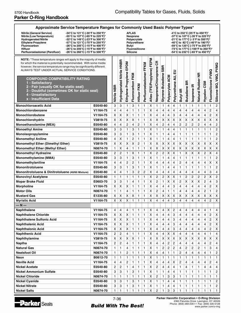
Parker O-Ring Handbook5700 Handbook Compatibility Tables for Gases, Fluids, Solids
NOTE: *These temperature ranges will apply to the majority of mediafor which the material is potentially recommended. With some mediahowever, the service temperature range may be significantly different.ALWAYS TEST UNDER ACTUAL SERVICE CONDITIONS.
Nitrile (General Service) -34°C to 121°C (-30°F to 250°F)*Nitrile (Low Temperature) -55°C to 107°C (-65°F to 225°F)*Hydrogenated Nitrile -32°C to 149°C (-23°F to 300°F)*Ethylene Propylene -57°C to 121°C (-70°F to 250°F)*Fluorocarbon -26°C to 205°C (-15°F to 400°F)*Hifluor -26°C to 205°C (-15°F to 400°F)*Perfluoroelastomer (Parofluor) -26°C to 260°C (-15°F to 500°F)*
Approximate Service Temperature Ranges for Commonly Used Basic Polymer Types*
COMPOUND COMPATIBILITY RATING1 - Satisfactory2 - Fair (usually OK for static seal)3 - Doubtful (sometimes OK for static seal)4 - Unsatisfactoryx - Insufficient Data
AFLAS -4°C to 232°C (25°F to 450°F)*Neoprene -37°C to 107°C (-35°F to 225°F)*Polyacrylate -21°C to 177°C (- 5°F to 350°F)*Polyurethane -40°C to 82°C (-40°F to 180°F)*Butyl -59°C to 120°C (-75°F to 250°F)*Fluorosilicone -73°C to 177°C (-100°F to 350°F)*Silicone -54°C to 232°C (-65°F to 450°F)*
Nitr
ile N
BR
Hyd
rog
enat
ed N
itrile
HN
BR
Eth
ylen
e P
ropy
len
e E
PD
M
Flu
oro
carb
on
FK
M
Hifl
uo
r F
KM
Per
fluo
roel
asto
mer
FF
KM
Afla
s (T
FE
/Pro
pyle
ne)
FE
PM
Neo
pre
ne/
Ch
loro
pre
ne
CR
Sty
ren
e-B
uta
die
ne
SB
R
Po
lyac
ryla
te A
CM
Po
lyu
reth
ane
AU
, EU
Bu
tyl I
IR
Bu
tad
ien
e B
R
Iso
pre
ne
IR
Nat
ura
l Ru
bb
er N
R
Hyp
alo
n C
SM
Flu
oro
silic
on
e F
VM
Q
Sili
con
e M
Q, V
MQ
, PV
MQ
7-36
Build With The Best!SealsParker Hannifin Corporation • O-Ring Division
2360 Palumbo Drive, Lexington, KY 40509Phone: (859) 269-2351 • Fax: (859) 335-5128
www.parker.com/o-ring
Monochloroacetic Acid E0540-80 3 3 1 3 1 1 X 1 1 4 4 1 1 1 1 1 1 2
Monochlorobenzene V1164-75 4 4 4 1 1 1 X 4 4 4 4 4 4 4 4 4 2 4
Monochlorobutene V1164-75 X X X 1 1 1 X 4 4 4 3 4 4 4 4 4 2 X
Monochlorohydrin V3819-75 X X X X 1 1 X X X X X X X X X X X X
Monoethanolamine (MEA) E0540-80 4 4 2 4 2 1 X 4 2 4 4 2 2 2 2 4 4 2
Monoethyl Amine E0540-80 3 3 1 3 1 1 X 1 1 4 4 1 1 1 1 1 1 2
Monoisopropylamine E0540-80 3 3 1 3 1 1 X 1 1 4 4 1 1 1 1 1 1 2
Monomethyl Aniline E0540-80 4 X 1 2 1 1 X 1 1 4 4 1 1 1 1 1 1 2
Monomethyl Ether (Dimethyl Ether) V3819-75 X X X X 2 1 X X X X X X X X X X X X
Monomethyl Ether (Methyl Ether) N0674-70 1 X 4 1 1 1 X X X X X X X X X X X X
Monomethyl Hydrazine E0540-80 2 2 1 X 1 1 X 2 2 X X 1 X X X 2 X 4
Monomethylamine (MMA) E0540-80 3 3 1 3 1 1 X 1 1 4 4 1 1 1 1 1 1 2
Monomethylaniline V1164-75 4 4 2 2 1 1 X 4 4 4 4 2 4 4 4 4 X X
Mononitrotoluene E0540-80 3 3 1 3 1 1 X 1 1 4 4 1 1 1 1 1 1 2
Mononitrotoluene & Dinitrotoluene (40/60 Mixture) E0540-80 4 4 1 3 2 2 X 4 4 4 4 4 4 4 4 4 3 4
Monovinyl Acetylene E0540-80 1 1 1 1 1 1 X 2 2 X X 1 2 2 2 2 X 2
Mopar Brake Fluid E0603-70 3 3 1 4 1 1 X 2 1 X X 2 X X X 2 4 3
Morpholine V1164-75 X X X 1 1 1 X 4 4 4 3 4 4 4 4 4 2 X
Motor Oils N0674-70 1 1 4 1 1 1 X 2 4 1 1 4 4 4 4 2 1 2
Mustard Gas E1235-80 X X X X 1 1 X X X X X X X X X X X X
Myristic Acid V1164-75 X X X 1 1 1 X 4 4 4 3 4 4 4 4 4 2 X
— N —
Naphthalene V1164-75 4 4 4 1 1 1 X 4 4 X 2 4 4 4 4 4 1 4
Naphthalene Chloride V1164-75 X X X 1 1 1 X 4 4 4 3 4 4 4 4 4 2 X
Naphthalene Sulfonic Acid V1164-75 X X X 1 1 1 X 4 4 4 3 4 4 4 4 4 2 X
Naphthalenic Acid V1164-75 X X X 1 1 1 X 4 4 4 3 4 4 4 4 4 2 X
Naphthalonic Acid V1164-75 X X X 1 1 1 X 4 4 4 3 4 4 4 4 4 2 X
Naphthenic Acid V1164-75 2 2 4 1 1 1 X 4 4 X X 4 4 4 4 4 1 4
Naphthylamine V3819-75 X X X X 1 1 X X X X X X X X X X X X
Naptha V1164-75 2 2 4 1 1 1 X 4 4 2 2 4 4 4 4 4 2 4
Natural Gas N0674-70 1 1 4 1 1 1 X 1 2 2 2 4 2 2 2 1 3 4
Neatsfoot Oil N0674-70 1 1 2 1 1 1 X 4 4 1 1 2 4 4 4 4 1 2
Neon B0612-70 1 1 1 1 1 1 X 1 1 1 1 1 1 1 1 1 1 1
Neville Acid V1164-75 4 4 2 1 1 1 X 4 4 4 X 2 4 4 4 4 2 4
Nickel Acetate E0540-80 2 2 1 4 1 1 X 2 4 4 4 1 4 1 1 4 4 4
Nickel Ammonium Sulfate E0540-80 3 3 1 3 1 1 X 1 1 4 4 1 1 1 1 1 1 2
Nickel Chloride N0674-70 1 1 1 1 1 1 X 2 1 3 3 1 1 1 1 1 1 1
Nickel Cyanide E0540-80 3 3 1 3 1 1 X 1 1 4 4 1 1 1 1 1 1 2
Nickel Nitrate E0540-80 3 3 1 3 1 1 X 1 1 4 4 1 1 1 1 1 1 2
Nickel Salts N0674-70 1 1 1 1 1 1 X 2 1 3 3 1 1 1 1 1 1 1

Parker O-Ring Handbook5700 Handbook Compatibility Tables for Gases, Fluids, Solids
NOTE: *These temperature ranges will apply to the majority of mediafor which the material is potentially recommended. With some mediahowever, the service temperature range may be significantly different.ALWAYS TEST UNDER ACTUAL SERVICE CONDITIONS.
Nitrile (General Service) -34°C to 121°C (-30°F to 250°F)*Nitrile (Low Temperature) -55°C to 107°C (-65°F to 225°F)*Hydrogenated Nitrile -32°C to 149°C (-23°F to 300°F)*Ethylene Propylene -57°C to 121°C (-70°F to 250°F)*Fluorocarbon -26°C to 205°C (-15°F to 400°F)*Hifluor -26°C to 205°C (-15°F to 400°F)*Perfluoroelastomer (Parofluor) -26°C to 260°C (-15°F to 500°F)*
Approximate Service Temperature Ranges for Commonly Used Basic Polymer Types*
COMPOUND COMPATIBILITY RATING1 - Satisfactory2 - Fair (usually OK for static seal)3 - Doubtful (sometimes OK for static seal)4 - Unsatisfactoryx - Insufficient Data
AFLAS -4°C to 232°C (25°F to 450°F)*Neoprene -37°C to 107°C (-35°F to 225°F)*Polyacrylate -21°C to 177°C (- 5°F to 350°F)*Polyurethane -40°C to 82°C (-40°F to 180°F)*Butyl -59°C to 120°C (-75°F to 250°F)*Fluorosilicone -73°C to 177°C (-100°F to 350°F)*Silicone -54°C to 232°C (-65°F to 450°F)*
Nitr
ile N
BR
Hyd
rog
enat
ed N
itrile
HN
BR
Eth
ylen
e P
ropy
len
e E
PD
M
Flu
oro
carb
on
FK
M
Hifl
uo
r F
KM
Per
fluo
roel
asto
mer
FF
KM
Afla
s (T
FE
/Pro
pyle
ne)
FE
PM
Neo
pre
ne/
Ch
loro
pre
ne
CR
Sty
ren
e-B
uta
die
ne
SB
R
Po
lyac
ryla
te A
CM
Po
lyu
reth
ane
AU
, EU
Bu
tyl I
IR
Bu
tad
ien
e B
R
Iso
pre
ne
IR
Nat
ura
l Ru
bb
er N
R
Hyp
alo
n C
SM
Flu
oro
silic
on
e F
VM
Q
Sili
con
e M
Q, V
MQ
, PV
MQ
7-37
Build With The Best!SealsParker Hannifin Corporation • O-Ring Division
2360 Palumbo Drive, Lexington, KY 40509Phone: (859) 269-2351 • Fax: (859) 335-5128
www.parker.com/o-ring
Nickel Sulfate N0674-70 1 1 1 1 1 1 X 1 2 4 3 1 2 2 2 1 1 1
Nicotinamide (Niacinamide) V1164-75 X X X 1 1 1 X 4 4 4 3 4 4 4 4 4 2 X
Nicotinamide Hydrochloride E0540-80 3 3 1 3 1 1 X 1 1 4 4 1 1 1 1 1 1 2
Nicotine V1164-75 X X X 1 1 1 X 4 4 4 3 4 4 4 4 4 2 X
Nicotine Sulfate E0540-80 3 3 1 3 1 1 X 1 1 4 4 1 1 1 1 1 1 2
Niter Cake N0674-70 1 1 1 1 1 1 X 1 1 4 1 1 1 1 1 1 1 1
Nitric Acid, Red Fuming V3819-75 4 4 4 2 1 1 3 4 X X X X X X X X X X
Nitric Acid, White Fuming V3819-75 X X X X 2 2 X X X X X X X X X X X X
Nitric Acid (0 - 50%) V1164-75 4 X 2 1 1 1 X X X X X X X X X X X X
Nitric Acid (50 - 100%) V3819-75 4 X 4 3 1 1 X X X X X X X X X X X X
Nitric Acid 3 Molar to 158°F E0540-80 4 4 2 3 2 2 X 4 3 4 4 2 X X X 2 4 4
Nitric Acid Concentrated Room Temp. V0834-70 X X 4 2 1 1 X X X X X X X X X X X X
Nitric Acid Concentrated to 158°F V3819-75 4 4 4 4 3 2 X 4 4 4 4 4 X X 4 X 4 4
Nitroaniline E0540-80 3 3 1 3 1 1 X 1 1 4 4 1 1 1 1 1 1 2
Nitrobenzene E0540-80 4 4 1 2 1 1 X 4 4 4 4 1 4 4 4 4 4 4
Nitrobenzoic Acid E0540-80 3 3 1 3 1 1 X 1 1 4 4 1 1 1 1 1 1 2
Nitrocellulose E0540-80 3 3 1 3 1 1 X 1 1 4 4 1 1 1 1 1 1 2
Nitrochlorobenzene E0540-80 3 3 1 3 1 1 X 1 1 4 4 1 1 1 1 1 1 2
Nitrochloroform E0540-80 3 3 1 3 1 1 X 1 1 4 4 1 1 1 1 1 1 2
Nitrodiethylaniline E0540-80 3 3 1 3 1 1 X 1 1 4 4 1 1 1 1 1 1 2
Nitrodiphenyl Ether V3819-75 X X X X 1 1 X X X X X X X X X X X X
Nitroethane E0540-80 4 4 2 4 1 1 X 2 2 4 4 2 2 2 2 2 4 4
Nitrofluorobenzene E0540-80 3 3 1 3 1 1 X 1 1 4 4 1 1 1 1 1 1 2
Nitrogen B0612-70 1 1 1 1 1 1 X 1 1 1 1 1 1 1 1 1 1 1
Nitrogen Oxides E0540-80 3 3 1 3 1 1 X 1 1 4 4 1 1 1 1 1 1 2
Nitrogen Tetroxide (N2O4) Factory 4 3 4 4 2 2 X 4 4 4 4 3 4 4 4 4 4 4
Nitrogen Trifluoride V3819-75 X X X X 2 2 X X X X X X X X X X X X
Nitroglycerine E0540-80 3 3 1 3 1 1 X 1 1 4 4 1 1 1 1 1 1 2
Nitrogylcerol E0540-80 3 3 1 3 1 1 X 1 1 4 4 1 1 1 1 1 1 2
Nitroisopropylbenzene E0540-80 3 3 1 3 1 1 X 1 1 4 4 1 1 1 1 1 1 2
Nitromethane E0540-80 4 4 2 4 1 1 X 3 3 4 4 2 2 2 2 2 4 4
Nitrophenol E0540-80 3 3 1 3 1 1 X 1 1 4 4 1 1 1 1 1 1 2
Nitropropane E0540-80 4 4 2 4 1 1 X 4 4 4 4 2 4 4 4 4 4 4
Nitrosyl Chloride V3819-75 X X X X 1 1 X X X X X X X X X X X X
Nitrosylsulfuric Acid V3819-75 X X X X 1 1 X X X X X X X X X X X X
Nitrothiophene E0540-80 3 3 1 3 1 1 X 1 1 4 4 1 1 1 1 1 1 2
Nitrotoluene E0540-80 3 3 1 3 1 1 X 1 1 4 4 1 1 1 1 1 1 2
Nitrous Acid E0540-80 3 3 1 3 1 1 X 1 1 4 4 1 1 1 1 1 1 2
Nitrous Oxide E0540-80 1 1 1 1 1 1 X X X X X X X X X X X 1
Nonane N0674-70 1 1 4 1 1 1 X 2 4 1 1 4 4 4 4 2 1 2

Parker O-Ring Handbook5700 Handbook Compatibility Tables for Gases, Fluids, Solids
NOTE: *These temperature ranges will apply to the majority of mediafor which the material is potentially recommended. With some mediahowever, the service temperature range may be significantly different.ALWAYS TEST UNDER ACTUAL SERVICE CONDITIONS.
Nitrile (General Service) -34°C to 121°C (-30°F to 250°F)*Nitrile (Low Temperature) -55°C to 107°C (-65°F to 225°F)*Hydrogenated Nitrile -32°C to 149°C (-23°F to 300°F)*Ethylene Propylene -57°C to 121°C (-70°F to 250°F)*Fluorocarbon -26°C to 205°C (-15°F to 400°F)*Hifluor -26°C to 205°C (-15°F to 400°F)*Perfluoroelastomer (Parofluor) -26°C to 260°C (-15°F to 500°F)*
Approximate Service Temperature Ranges for Commonly Used Basic Polymer Types*
COMPOUND COMPATIBILITY RATING1 - Satisfactory2 - Fair (usually OK for static seal)3 - Doubtful (sometimes OK for static seal)4 - Unsatisfactoryx - Insufficient Data
AFLAS -4°C to 232°C (25°F to 450°F)*Neoprene -37°C to 107°C (-35°F to 225°F)*Polyacrylate -21°C to 177°C (- 5°F to 350°F)*Polyurethane -40°C to 82°C (-40°F to 180°F)*Butyl -59°C to 120°C (-75°F to 250°F)*Fluorosilicone -73°C to 177°C (-100°F to 350°F)*Silicone -54°C to 232°C (-65°F to 450°F)*
Nitr
ile N
BR
Hyd
rog
enat
ed N
itrile
HN
BR
Eth
ylen
e P
ropy
len
e E
PD
M
Flu
oro
carb
on
FK
M
Hifl
uo
r F
KM
Per
fluo
roel
asto
mer
FF
KM
Afla
s (T
FE
/Pro
pyle
ne)
FE
PM
Neo
pre
ne/
Ch
loro
pre
ne
CR
Sty
ren
e-B
uta
die
ne
SB
R
Po
lyac
ryla
te A
CM
Po
lyu
reth
ane
AU
, EU
Bu
tyl I
IR
Bu
tad
ien
e B
R
Iso
pre
ne
IR
Nat
ura
l Ru
bb
er N
R
Hyp
alo
n C
SM
Flu
oro
silic
on
e F
VM
Q
Sili
con
e M
Q, V
MQ
, PV
MQ
7-38
Build With The Best!SealsParker Hannifin Corporation • O-Ring Division
2360 Palumbo Drive, Lexington, KY 40509Phone: (859) 269-2351 • Fax: (859) 335-5128
www.parker.com/o-ring
Noryl GE Phenolic N0674-70 1 1 1 X X X X X X X X X X X X X X X
Nyvac FR200 Mobil N0674-70 1 1 1 1 1 1 X 2 4 X X 4 4 X 4 3 X X
— O —
Octachloro Toluene V1164-75 4 4 4 1 1 1 X 4 4 4 4 4 4 4 4 4 2 4
Octadecane N0674-70 1 1 4 1 1 1 X 2 4 2 1 4 4 4 4 2 1 4
Octanal (n-Octanaldehyde) N0674-70 1 1 4 1 1 1 X 2 4 1 1 4 4 4 4 2 1 2
Octane or n-Octane V1164-75 1 1 4 1 1 1 X 4 4 4 4 4 4 4 4 4 2 4
Octyl Acetate E0540-80 3 3 1 3 1 1 X 1 1 4 4 1 1 1 1 1 1 2
Octyl Alcohol V1164-75 2 2 3 1 1 1 X 2 2 4 4 2 2 2 2 2 2 2
Octyl Chloride N0674-70 1 1 4 1 1 1 X 2 4 1 1 4 4 4 4 2 1 2
Octyl Phthalate V1164-75 X X X 1 1 1 X 4 4 4 3 4 4 4 4 4 2 X
Olefins V1164-75 X X X 1 1 1 X 4 4 4 3 4 4 4 4 4 2 X
Oleic Acid V0834-70 3 3 4 2 1 1 X 4 4 4 2 4 4 4 4 4 X 4
Oleum (Fuming Sulfuric Acid) V1164-75 4 4 4 1 1 1 X 4 4 4 4 4 4 4 4 4 X 4
Oleum Spirits V1164-75 2 2 4 1 1 1 X 3 4 X 3 4 4 4 4 2 2 4
Oleyl Alcohol V1164-75 X X X 1 1 1 X 4 4 4 3 4 4 4 4 4 2 X
Olive Oil N0674-70 1 1 2 1 1 1 X 2 4 1 1 2 4 4 4 2 1 3
Oronite 8200 V1164-75 2 2 4 1 1 1 X 1 4 X 1 4 4 4 4 4 1 4
Oronite 8515 V1164-75 2 2 4 1 1 1 X 1 4 X 1 4 4 4 4 4 1 4
Ortho-Chloro Ethyl Benzene V1164-75 4 4 4 1 1 1 X 4 4 4 4 4 4 4 4 4 2 4
Ortho-Chloroaniline E0540-80 3 3 1 3 1 1 X 1 1 4 4 1 1 1 1 1 1 2
Ortho-Chlorophenol E0540-80 3 3 1 3 1 1 X 1 1 4 4 1 1 1 1 1 1 2
Ortho-Cresol E0540-80 3 3 1 3 1 1 X 1 1 4 4 1 1 1 1 1 1 2
Ortho-Dichlorobenzene V1164-75 4 4 4 1 1 1 X 4 4 4 4 4 4 4 4 4 2 4
Ortho-Nitrotoluene E0540-80 3 3 1 3 1 1 X 1 1 4 4 1 1 1 1 1 1 2
Orthophos Acid V3819-75 X X X X 1 1 X X X X X X X X X X X X
OS 45 Type III (OS45) V1164-75 2 2 4 1 1 1 X 1 4 X 4 4 4 4 4 2 2 4
OS 45 Type IV (OS45-1) V1164-75 2 2 4 1 1 1 X 1 4 X 4 4 4 4 4 2 2 4
OS 70 V1164-75 2 2 4 1 1 1 X 1 4 X 4 4 4 4 4 2 2 4
Oxalic Acid E0540-80 2 2 1 1 1 1 X 2 2 X X 1 2 2 2 2 1 2
Oxygen, 200°-300°F (Evalute for specific applications) V1164-75 4 4 4 2 1 1
Oxygen, 300°-400°F (Evalute for specific applications) S0604-70 4 4 4 2 1 1 X 4 4 4 4 4 4 4 4 4 4 1
Oxygen, Cold (Evalute for specific applications) C0873-70 2 2 1 1 1 1 X 1 2 2 1 1 2 2 2 1 1 1
Oxygen, Liquid V3819-75 4 4 4 4 3 2 4 4 X X X X X X X X X X
Ozonated Deionized Water E0540-80 3 3 1 3 2 2 X 1 1 4 4 1 1 1 1 1 1 2
Ozone E0540-80 4 4 1 1 1 1 X 2 4 2 1 2 4 4 4 1 1 1
— P —
Paint Thinner, Duco V1164-75 4 4 4 2 1 1 X 4 4 4 4 4 4 4 4 4 2 4
Palmitic Acid N0674-70 1 1 2 1 1 1 X 2 2 X 1 2 2 2 2 3 1 4
Para-Aminobenzoic Acid E0540-80 3 3 1 3 1 1 X 1 1 4 4 1 1 1 1 1 1 2

Parker O-Ring Handbook5700 Handbook Compatibility Tables for Gases, Fluids, Solids
NOTE: *These temperature ranges will apply to the majority of mediafor which the material is potentially recommended. With some mediahowever, the service temperature range may be significantly different.ALWAYS TEST UNDER ACTUAL SERVICE CONDITIONS.
Nitrile (General Service) -34°C to 121°C (-30°F to 250°F)*Nitrile (Low Temperature) -55°C to 107°C (-65°F to 225°F)*Hydrogenated Nitrile -32°C to 149°C (-23°F to 300°F)*Ethylene Propylene -57°C to 121°C (-70°F to 250°F)*Fluorocarbon -26°C to 205°C (-15°F to 400°F)*Hifluor -26°C to 205°C (-15°F to 400°F)*Perfluoroelastomer (Parofluor) -26°C to 260°C (-15°F to 500°F)*
Approximate Service Temperature Ranges for Commonly Used Basic Polymer Types*
COMPOUND COMPATIBILITY RATING1 - Satisfactory2 - Fair (usually OK for static seal)3 - Doubtful (sometimes OK for static seal)4 - Unsatisfactoryx - Insufficient Data
AFLAS -4°C to 232°C (25°F to 450°F)*Neoprene -37°C to 107°C (-35°F to 225°F)*Polyacrylate -21°C to 177°C (- 5°F to 350°F)*Polyurethane -40°C to 82°C (-40°F to 180°F)*Butyl -59°C to 120°C (-75°F to 250°F)*Fluorosilicone -73°C to 177°C (-100°F to 350°F)*Silicone -54°C to 232°C (-65°F to 450°F)*
Nitr
ile N
BR
Hyd
rog
enat
ed N
itrile
HN
BR
Eth
ylen
e P
ropy
len
e E
PD
M
Flu
oro
carb
on
FK
M
Hifl
uo
r F
KM
Per
fluo
roel
asto
mer
FF
KM
Afla
s (T
FE
/Pro
pyle
ne)
FE
PM
Neo
pre
ne/
Ch
loro
pre
ne
CR
Sty
ren
e-B
uta
die
ne
SB
R
Po
lyac
ryla
te A
CM
Po
lyu
reth
ane
AU
, EU
Bu
tyl I
IR
Bu
tad
ien
e B
R
Iso
pre
ne
IR
Nat
ura
l Ru
bb
er N
R
Hyp
alo
n C
SM
Flu
oro
silic
on
e F
VM
Q
Sili
con
e M
Q, V
MQ
, PV
MQ
7-39
Build With The Best!SealsParker Hannifin Corporation • O-Ring Division
2360 Palumbo Drive, Lexington, KY 40509Phone: (859) 269-2351 • Fax: (859) 335-5128
www.parker.com/o-ring
Para-Aminosalicylic Acid E0540-80 3 3 1 3 1 1 X 1 1 4 4 1 1 1 1 1 1 2
Para-Bromobenzylphenyl Ether V3819-75 X X X X 1 1 X X X X X X X X X X X X
Para-Chlorophenol E0540-80 3 3 1 3 1 1 X 1 1 4 4 1 1 1 1 1 1 2
Paracymene V1164-75 X X X 1 1 1 X 4 4 4 3 4 4 4 4 4 2 X
Para-Dichlorobenzene V1164-75 4 4 4 1 1 1 X 4 4 4 4 4 4 4 4 4 2 4
Paraffins N0674-70 1 1 4 1 1 1 X 2 4 1 1 4 4 4 4 2 1 2
Para-Formaldehyde E0540-80 3 3 1 3 1 1 X 1 1 4 4 1 1 1 1 1 1 2
Paraldehyde E0540-80 3 3 1 3 1 1 X 1 1 4 4 1 1 1 1 1 1 2
Par-al-Ketone Factory 4 4 4 4 X X X 4 4 4 4 4 4 4 4 4 4 4
Para-Nitroaniline E0540-80 3 3 1 3 1 1 X 1 1 4 4 1 1 1 1 1 1 2
Para-Nitrobenzoic Acid E0540-80 3 3 1 3 1 1 X 1 1 4 4 1 1 1 1 1 1 2
Para-Nitrophenol E0540-80 3 3 1 3 1 1 X 1 1 4 4 1 1 1 1 1 1 2
Parathion V1164-75 X X X 1 1 1 X 4 4 4 3 4 4 4 4 4 2 X
Para-Toluene Sulfonic Acid E0540-80 3 3 1 3 1 1 X 1 1 4 4 1 1 1 1 1 1 2
Parker O Lube N0674-70 1 1 4 1 1 1 X 1 2 1 1 4 4 4 4 1 1 2
Peanut Oil N0674-70 1 1 3 1 1 1 X 3 4 1 2 3 4 4 4 2 1 1
Pectin (Liquor) V1164-75 X X X 1 1 1 X 4 4 4 3 4 4 4 4 4 2 X
Pelagonic Acid V3819-75 X X X X 1 1 X X X X X X X X X X X X
Penicillin (Liquid) V1164-75 X X X 1 1 1 X 4 4 4 3 4 4 4 4 4 2 X
Pentachloroethane V1164-75 X X X 1 1 1 X 4 4 4 3 4 4 4 4 4 2 X
Pentachlorophenol E0540-80 3 3 1 3 1 1 X 1 1 4 4 1 1 1 1 1 1 2
Pentaerythritol E0540-80 3 3 1 3 1 1 X 1 1 4 4 1 1 1 1 1 1 2
Pentaerythritol Tetranitrate E0540-80 3 3 1 3 1 1 X 1 1 4 4 1 1 1 1 1 1 2
Pentafluoroethane (F-125) V3819-75 X X X X 2 2 X X X X X X X X X X X X
Pentane or n-Pentane N0674-70 1 1 4 1 1 1 X 1 3 1 4 4 4 4 4 2 3 4
Pentane, 2 Methyl N0674-70 1 1 4 1 1 1 X 2 4 1 4 4 4 4 4 2 3 4
Pentane, 2-4 dimethyl N0674-70 1 1 4 1 1 1 X 2 4 1 4 4 4 4 4 2 3 4
Pentane, 3-Methyl N0674-70 1 1 4 1 1 1 X 2 4 1 4 4 4 4 4 2 3 4
Pentoxone V3819-75 X X X X 1 1 X X X X X X X X X X X X
Pentyl Pentanoate N0674-70 1 1 4 1 1 1 X 2 4 1 1 4 4 4 4 2 1 2
Peracetic Acid E0540-80 3 3 1 3 1 1 X 1 1 4 4 1 1 1 1 1 1 2
Perchloric Acid - 2N E0540-80 4 4 1 1 1 1 X 2 4 4 4 2 4 4 4 2 1 2
Perchloroethylene V1164-75 2 2 4 1 1 1 X 4 4 4 4 4 4 4 4 4 2 4
Perfluoropropane V3819-75 X X X X 2 2 X X X X X X X X X X X X
Perfluorotriethylamine V3819-75 X X X X 2 2 X X X X X X X X X X X X
Permanganic Acid V8545-75 X X X X 1 1 X X X X X X X X X X X X
Persulfuric Acid (Caro’s Acid) V3819-75 X X X X 1 1 X X X X X X X X X X X X
Petrolatum N0674-70 1 1 4 1 1 1 X 2 4 1 1 4 4 4 4 2 1 4
Petrolatum Ether N0674-70 1 1 4 1 1 1 X 2 4 1 1 4 4 4 4 2 1 2
Petroleum Oil, Above 250°F V1164-75 4 4 4 2 1 1 X 4 4 4 4 4 4 4 4 4 4 4
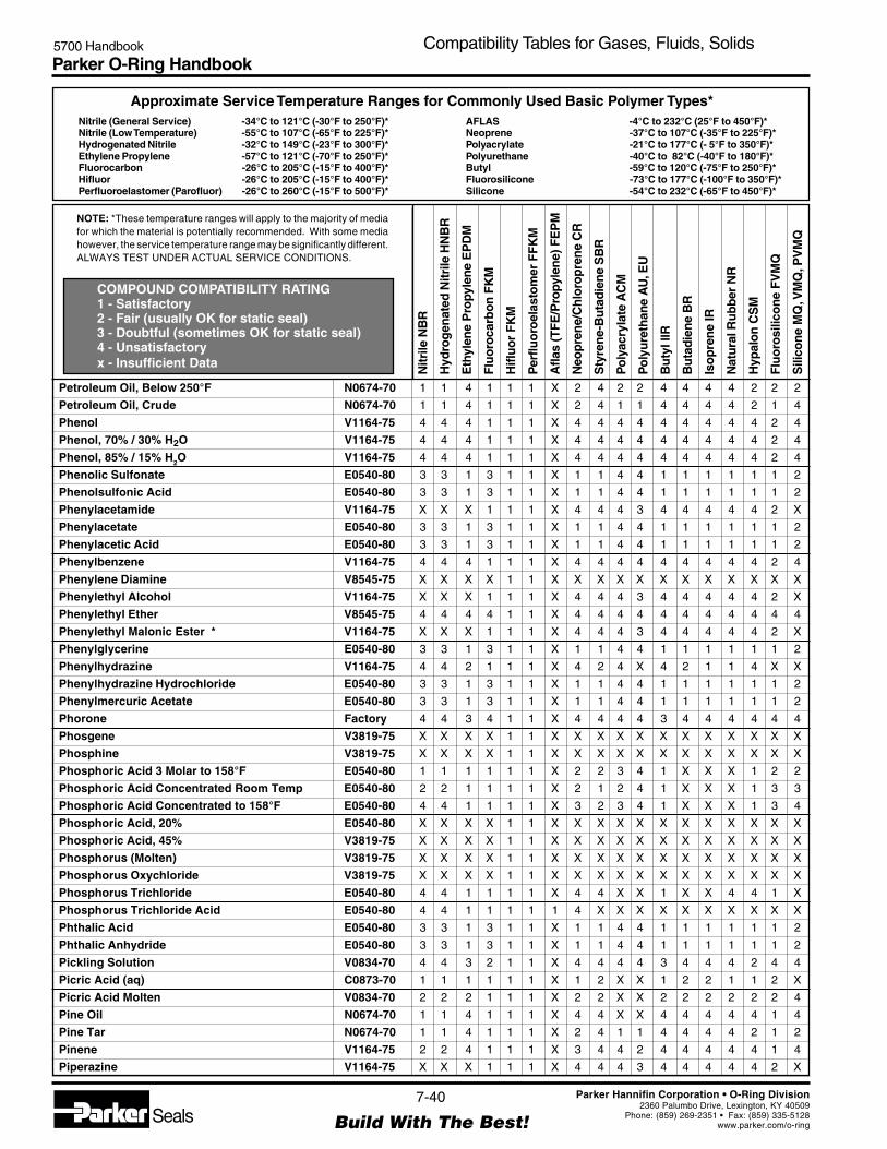
Parker O-Ring Handbook5700 Handbook Compatibility Tables for Gases, Fluids, Solids
NOTE: *These temperature ranges will apply to the majority of mediafor which the material is potentially recommended. With some mediahowever, the service temperature range may be significantly different.ALWAYS TEST UNDER ACTUAL SERVICE CONDITIONS.
Nitrile (General Service) -34°C to 121°C (-30°F to 250°F)*Nitrile (Low Temperature) -55°C to 107°C (-65°F to 225°F)*Hydrogenated Nitrile -32°C to 149°C (-23°F to 300°F)*Ethylene Propylene -57°C to 121°C (-70°F to 250°F)*Fluorocarbon -26°C to 205°C (-15°F to 400°F)*Hifluor -26°C to 205°C (-15°F to 400°F)*Perfluoroelastomer (Parofluor) -26°C to 260°C (-15°F to 500°F)*
Approximate Service Temperature Ranges for Commonly Used Basic Polymer Types*
COMPOUND COMPATIBILITY RATING1 - Satisfactory2 - Fair (usually OK for static seal)3 - Doubtful (sometimes OK for static seal)4 - Unsatisfactoryx - Insufficient Data
AFLAS -4°C to 232°C (25°F to 450°F)*Neoprene -37°C to 107°C (-35°F to 225°F)*Polyacrylate -21°C to 177°C (- 5°F to 350°F)*Polyurethane -40°C to 82°C (-40°F to 180°F)*Butyl -59°C to 120°C (-75°F to 250°F)*Fluorosilicone -73°C to 177°C (-100°F to 350°F)*Silicone -54°C to 232°C (-65°F to 450°F)*
Nitr
ile N
BR
Hyd
rog
enat
ed N
itrile
HN
BR
Eth
ylen
e P
ropy
len
e E
PD
M
Flu
oro
carb
on
FK
M
Hifl
uo
r F
KM
Per
fluo
roel
asto
mer
FF
KM
Afla
s (T
FE
/Pro
pyle
ne)
FE
PM
Neo
pre
ne/
Ch
loro
pre
ne
CR
Sty
ren
e-B
uta
die
ne
SB
R
Po
lyac
ryla
te A
CM
Po
lyu
reth
ane
AU
, EU
Bu
tyl I
IR
Bu
tad
ien
e B
R
Iso
pre
ne
IR
Nat
ura
l Ru
bb
er N
R
Hyp
alo
n C
SM
Flu
oro
silic
on
e F
VM
Q
Sili
con
e M
Q, V
MQ
, PV
MQ
7-40
Build With The Best!SealsParker Hannifin Corporation • O-Ring Division
2360 Palumbo Drive, Lexington, KY 40509Phone: (859) 269-2351 • Fax: (859) 335-5128
www.parker.com/o-ring
Petroleum Oil, Below 250°F N0674-70 1 1 4 1 1 1 X 2 4 2 2 4 4 4 4 2 2 2
Petroleum Oil, Crude N0674-70 1 1 4 1 1 1 X 2 4 1 1 4 4 4 4 2 1 4
Phenol V1164-75 4 4 4 1 1 1 X 4 4 4 4 4 4 4 4 4 2 4
Phenol, 70% / 30% H2O V1164-75 4 4 4 1 1 1 X 4 4 4 4 4 4 4 4 4 2 4
Phenol, 85% / 15% H2O V1164-75 4 4 4 1 1 1 X 4 4 4 4 4 4 4 4 4 2 4
Phenolic Sulfonate E0540-80 3 3 1 3 1 1 X 1 1 4 4 1 1 1 1 1 1 2
Phenolsulfonic Acid E0540-80 3 3 1 3 1 1 X 1 1 4 4 1 1 1 1 1 1 2
Phenylacetamide V1164-75 X X X 1 1 1 X 4 4 4 3 4 4 4 4 4 2 X
Phenylacetate E0540-80 3 3 1 3 1 1 X 1 1 4 4 1 1 1 1 1 1 2
Phenylacetic Acid E0540-80 3 3 1 3 1 1 X 1 1 4 4 1 1 1 1 1 1 2
Phenylbenzene V1164-75 4 4 4 1 1 1 X 4 4 4 4 4 4 4 4 4 2 4
Phenylene Diamine V8545-75 X X X X 1 1 X X X X X X X X X X X X
Phenylethyl Alcohol V1164-75 X X X 1 1 1 X 4 4 4 3 4 4 4 4 4 2 X
Phenylethyl Ether V8545-75 4 4 4 4 1 1 X 4 4 4 4 4 4 4 4 4 4 4
Phenylethyl Malonic Ester * V1164-75 X X X 1 1 1 X 4 4 4 3 4 4 4 4 4 2 X
Phenylglycerine E0540-80 3 3 1 3 1 1 X 1 1 4 4 1 1 1 1 1 1 2
Phenylhydrazine V1164-75 4 4 2 1 1 1 X 4 2 4 X 4 2 1 1 4 X X
Phenylhydrazine Hydrochloride E0540-80 3 3 1 3 1 1 X 1 1 4 4 1 1 1 1 1 1 2
Phenylmercuric Acetate E0540-80 3 3 1 3 1 1 X 1 1 4 4 1 1 1 1 1 1 2
Phorone Factory 4 4 3 4 1 1 X 4 4 4 4 3 4 4 4 4 4 4
Phosgene V3819-75 X X X X 1 1 X X X X X X X X X X X X
Phosphine V3819-75 X X X X 1 1 X X X X X X X X X X X X
Phosphoric Acid 3 Molar to 158°F E0540-80 1 1 1 1 1 1 X 2 2 3 4 1 X X X 1 2 2
Phosphoric Acid Concentrated Room Temp E0540-80 2 2 1 1 1 1 X 2 1 2 4 1 X X X 1 3 3
Phosphoric Acid Concentrated to 158°F E0540-80 4 4 1 1 1 1 X 3 2 3 4 1 X X X 1 3 4
Phosphoric Acid, 20% E0540-80 X X X X 1 1 X X X X X X X X X X X X
Phosphoric Acid, 45% V3819-75 X X X X 1 1 X X X X X X X X X X X X
Phosphorus (Molten) V3819-75 X X X X 1 1 X X X X X X X X X X X X
Phosphorus Oxychloride V3819-75 X X X X 1 1 X X X X X X X X X X X X
Phosphorus Trichloride E0540-80 4 4 1 1 1 1 X 4 4 X X 1 X X 4 4 1 X
Phosphorus Trichloride Acid E0540-80 4 4 1 1 1 1 1 4 X X X X X X X X X X
Phthalic Acid E0540-80 3 3 1 3 1 1 X 1 1 4 4 1 1 1 1 1 1 2
Phthalic Anhydride E0540-80 3 3 1 3 1 1 X 1 1 4 4 1 1 1 1 1 1 2
Pickling Solution V0834-70 4 4 3 2 1 1 X 4 4 4 4 3 4 4 4 2 4 4
Picric Acid (aq) C0873-70 1 1 1 1 1 1 X 1 2 X X 1 2 2 1 1 2 X
Picric Acid Molten V0834-70 2 2 2 1 1 1 X 2 2 X X 2 2 2 2 2 2 4
Pine Oil N0674-70 1 1 4 1 1 1 X 4 4 X X 4 4 4 4 4 1 4
Pine Tar N0674-70 1 1 4 1 1 1 X 2 4 1 1 4 4 4 4 2 1 2
Pinene V1164-75 2 2 4 1 1 1 X 3 4 4 2 4 4 4 4 4 1 4
Piperazine V1164-75 X X X 1 1 1 X 4 4 4 3 4 4 4 4 4 2 X
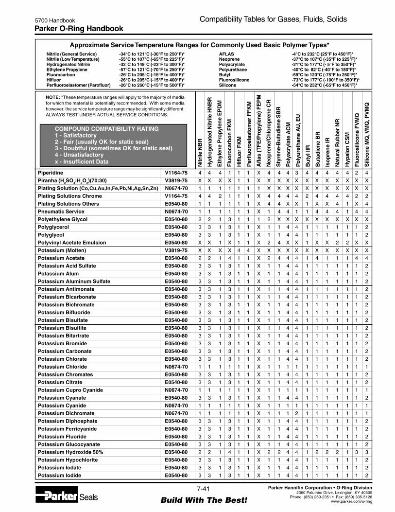
Parker O-Ring Handbook5700 Handbook Compatibility Tables for Gases, Fluids, Solids
NOTE: *These temperature ranges will apply to the majority of mediafor which the material is potentially recommended. With some mediahowever, the service temperature range may be significantly different.ALWAYS TEST UNDER ACTUAL SERVICE CONDITIONS.
Nitrile (General Service) -34°C to 121°C (-30°F to 250°F)*Nitrile (Low Temperature) -55°C to 107°C (-65°F to 225°F)*Hydrogenated Nitrile -32°C to 149°C (-23°F to 300°F)*Ethylene Propylene -57°C to 121°C (-70°F to 250°F)*Fluorocarbon -26°C to 205°C (-15°F to 400°F)*Hifluor -26°C to 205°C (-15°F to 400°F)*Perfluoroelastomer (Parofluor) -26°C to 260°C (-15°F to 500°F)*
Approximate Service Temperature Ranges for Commonly Used Basic Polymer Types*
COMPOUND COMPATIBILITY RATING1 - Satisfactory2 - Fair (usually OK for static seal)3 - Doubtful (sometimes OK for static seal)4 - Unsatisfactoryx - Insufficient Data
AFLAS -4°C to 232°C (25°F to 450°F)*Neoprene -37°C to 107°C (-35°F to 225°F)*Polyacrylate -21°C to 177°C (- 5°F to 350°F)*Polyurethane -40°C to 82°C (-40°F to 180°F)*Butyl -59°C to 120°C (-75°F to 250°F)*Fluorosilicone -73°C to 177°C (-100°F to 350°F)*Silicone -54°C to 232°C (-65°F to 450°F)*
Nitr
ile N
BR
Hyd
rog
enat
ed N
itrile
HN
BR
Eth
ylen
e P
ropy
len
e E
PD
M
Flu
oro
carb
on
FK
M
Hifl
uo
r F
KM
Per
fluo
roel
asto
mer
FF
KM
Afla
s (T
FE
/Pro
pyle
ne)
FE
PM
Neo
pre
ne/
Ch
loro
pre
ne
CR
Sty
ren
e-B
uta
die
ne
SB
R
Po
lyac
ryla
te A
CM
Po
lyu
reth
ane
AU
, EU
Bu
tyl I
IR
Bu
tad
ien
e B
R
Iso
pre
ne
IR
Nat
ura
l Ru
bb
er N
R
Hyp
alo
n C
SM
Flu
oro
silic
on
e F
VM
Q
Sili
con
e M
Q, V
MQ
, PV
MQ
7-41
Build With The Best!SealsParker Hannifin Corporation • O-Ring Division
2360 Palumbo Drive, Lexington, KY 40509Phone: (859) 269-2351 • Fax: (859) 335-5128
www.parker.com/o-ring
Piperidine V1164-75 4 4 4 1 1 1 X 4 4 4 3 4 4 4 4 4 2 4
Piranha (H2SO4:H2O2)(70:30) V3819-75 X X X X 1 1 X X X X X X X X X X X X
Plating Solution (Co,Cu,Au,In,Fe,Pb,Ni,Ag,Sn,Zn) N0674-70 1 1 1 1 1 1 1 X X X X X X X X X X X
Plating Solutions Chrome V1164-75 4 4 2 1 1 1 X 4 4 4 4 2 4 4 4 4 2 2
Plating Solutions Others E0540-80 1 1 1 1 1 1 X 4 4 X X 1 X X 4 1 X 4
Pneumatic Service N0674-70 1 1 1 1 1 1 X 1 4 4 1 1 4 4 4 1 4 4
Polyethylene Glycol E0540-80 2 2 1 3 1 1 1 2 X X X X X X X X X X
Polyglycerol E0540-80 3 3 1 3 1 1 X 1 1 4 4 1 1 1 1 1 1 2
Polyglycol E0540-80 3 3 1 3 1 1 X 1 1 4 4 1 1 1 1 1 1 2
Polyvinyl Acetate Emulsion E0540-80 X X 1 X 1 1 X 2 4 X X 1 X X 2 2 X X
Potassium (Molten) V3819-75 X X X X 4 4 X X X X X X X X X X X X
Potassium Acetate E0540-80 2 2 1 4 1 1 X 2 4 4 4 1 4 1 1 1 4 4
Potassium Acid Sulfate E0540-80 3 3 1 3 1 1 X 1 1 4 4 1 1 1 1 1 1 2
Potassium Alum E0540-80 3 3 1 3 1 1 X 1 1 4 4 1 1 1 1 1 1 2
Potassium Aluminum Sulfate E0540-80 3 3 1 3 1 1 X 1 1 4 4 1 1 1 1 1 1 2
Potassium Antimonate E0540-80 3 3 1 3 1 1 X 1 1 4 4 1 1 1 1 1 1 2
Potassium Bicarbonate E0540-80 3 3 1 3 1 1 X 1 1 4 4 1 1 1 1 1 1 2
Potassium Bichromate E0540-80 3 3 1 3 1 1 X 1 1 4 4 1 1 1 1 1 1 2
Potassium Bifluoride E0540-80 3 3 1 3 1 1 X 1 1 4 4 1 1 1 1 1 1 2
Potassium Bisulfate E0540-80 3 3 1 3 1 1 X 1 1 4 4 1 1 1 1 1 1 2
Potassium Bisulfite E0540-80 3 3 1 3 1 1 X 1 1 4 4 1 1 1 1 1 1 2
Potassium Bitartrate E0540-80 3 3 1 3 1 1 X 1 1 4 4 1 1 1 1 1 1 2
Potassium Bromide E0540-80 3 3 1 3 1 1 X 1 1 4 4 1 1 1 1 1 1 2
Potassium Carbonate E0540-80 3 3 1 3 1 1 X 1 1 4 4 1 1 1 1 1 1 2
Potassium Chlorate E0540-80 3 3 1 3 1 1 X 1 1 4 4 1 1 1 1 1 1 2
Potassium Chloride N0674-70 1 1 1 1 1 1 X 1 1 1 1 1 1 1 1 1 1 1
Potassium Chromates E0540-80 3 3 1 3 1 1 X 1 1 4 4 1 1 1 1 1 1 2
Potassium Citrate E0540-80 3 3 1 3 1 1 X 1 1 4 4 1 1 1 1 1 1 2
Potassium Cupro Cyanide N0674-70 1 1 1 1 1 1 X 1 1 1 1 1 1 1 1 1 1 1
Potassium Cyanate E0540-80 3 3 1 3 1 1 X 1 1 4 4 1 1 1 1 1 1 2
Potassium Cyanide N0674-70 1 1 1 1 1 1 X 1 1 1 1 1 1 1 1 1 1 1
Potassium Dichromate N0674-70 1 1 1 1 1 1 X 1 1 1 2 1 1 1 1 1 1 1
Potassium Diphosphate E0540-80 3 3 1 3 1 1 X 1 1 4 4 1 1 1 1 1 1 2
Potassium Ferricyanide E0540-80 3 3 1 3 1 1 X 1 1 4 4 1 1 1 1 1 1 2
Potassium Fluoride E0540-80 3 3 1 3 1 1 X 1 1 4 4 1 1 1 1 1 1 2
Potassium Glucocyanate E0540-80 3 3 1 3 1 1 X 1 1 4 4 1 1 1 1 1 1 2
Potassium Hydroxide 50% E0540-80 2 2 1 4 1 1 X 2 2 4 4 1 2 2 2 1 3 3
Potassium Hypochlorite E0540-80 3 3 1 3 1 1 X 1 1 4 4 1 1 1 1 1 1 2
Potassium Iodate E0540-80 3 3 1 3 1 1 X 1 1 4 4 1 1 1 1 1 1 2
Potassium Iodide E0540-80 3 3 1 3 1 1 X 1 1 4 4 1 1 1 1 1 1 2

Parker O-Ring Handbook5700 Handbook Compatibility Tables for Gases, Fluids, Solids
NOTE: *These temperature ranges will apply to the majority of mediafor which the material is potentially recommended. With some mediahowever, the service temperature range may be significantly different.ALWAYS TEST UNDER ACTUAL SERVICE CONDITIONS.
Nitrile (General Service) -34°C to 121°C (-30°F to 250°F)*Nitrile (Low Temperature) -55°C to 107°C (-65°F to 225°F)*Hydrogenated Nitrile -32°C to 149°C (-23°F to 300°F)*Ethylene Propylene -57°C to 121°C (-70°F to 250°F)*Fluorocarbon -26°C to 205°C (-15°F to 400°F)*Hifluor -26°C to 205°C (-15°F to 400°F)*Perfluoroelastomer (Parofluor) -26°C to 260°C (-15°F to 500°F)*
Approximate Service Temperature Ranges for Commonly Used Basic Polymer Types*
COMPOUND COMPATIBILITY RATING1 - Satisfactory2 - Fair (usually OK for static seal)3 - Doubtful (sometimes OK for static seal)4 - Unsatisfactoryx - Insufficient Data
AFLAS -4°C to 232°C (25°F to 450°F)*Neoprene -37°C to 107°C (-35°F to 225°F)*Polyacrylate -21°C to 177°C (- 5°F to 350°F)*Polyurethane -40°C to 82°C (-40°F to 180°F)*Butyl -59°C to 120°C (-75°F to 250°F)*Fluorosilicone -73°C to 177°C (-100°F to 350°F)*Silicone -54°C to 232°C (-65°F to 450°F)*
Nitr
ile N
BR
Hyd
rog
enat
ed N
itrile
HN
BR
Eth
ylen
e P
ropy
len
e E
PD
M
Flu
oro
carb
on
FK
M
Hifl
uo
r F
KM
Per
fluo
roel
asto
mer
FF
KM
Afla
s (T
FE
/Pro
pyle
ne)
FE
PM
Neo
pre
ne/
Ch
loro
pre
ne
CR
Sty
ren
e-B
uta
die
ne
SB
R
Po
lyac
ryla
te A
CM
Po
lyu
reth
ane
AU
, EU
Bu
tyl I
IR
Bu
tad
ien
e B
R
Iso
pre
ne
IR
Nat
ura
l Ru
bb
er N
R
Hyp
alo
n C
SM
Flu
oro
silic
on
e F
VM
Q
Sili
con
e M
Q, V
MQ
, PV
MQ
7-42
Build With The Best!SealsParker Hannifin Corporation • O-Ring Division
2360 Palumbo Drive, Lexington, KY 40509Phone: (859) 269-2351 • Fax: (859) 335-5128
www.parker.com/o-ring
Potassium Metabisulfate E0540-80 3 3 1 3 1 1 X 1 1 4 4 1 1 1 1 1 1 2
Potassium Metachromate E0540-80 3 3 1 3 1 1 X 1 1 4 4 1 1 1 1 1 1 2
Potassium Metasilicate V3819-75 X X X X 1 1 X X X X X X X X X X X X
Potassium Monochromate E0540-80 3 3 1 3 1 1 X 1 1 4 4 1 1 1 1 1 1 2
Potassium Nitrate N0674-70 1 1 1 1 1 1 X 1 1 1 1 1 1 1 1 1 1 1
Potassium Nitrite E0540-80 3 3 1 3 1 1 X 1 1 4 4 1 1 1 1 1 1 2
Potassium Oxalate E0540-80 3 3 1 3 1 1 X 1 1 4 4 1 1 1 1 1 1 2
Potassium Perchlorate E0540-80 3 3 1 3 1 1 X 1 1 4 4 1 1 1 1 1 1 2
Potassium Perfluoro Acetate V3819-75 X X X X 2 1 X X X X X X X X X X X X
Potassium Permanganate E0540-80 3 3 1 3 1 1 X 1 1 4 4 1 1 1 1 1 1 2
Potassium Peroxide V3819-75 X X X X 1 1 X X X X X X X X X X X X
Potassium Persulfate E0540-80 3 3 1 3 1 1 X 1 1 4 4 1 1 1 1 1 1 2
Potassium Phosphate (Acid) E0540-80 3 3 1 3 1 1 X 1 1 4 4 1 1 1 1 1 1 2
Potassium Phosphate (Alkaline) E0540-80 3 3 1 3 1 1 X 1 1 4 4 1 1 1 1 1 1 2
Potassium Phosphate (Di/Tri Basic) E0540-80 3 3 1 3 1 1 X 1 1 4 4 1 1 1 1 1 1 2
Potassium Pyrosulfate E0540-80 3 3 1 3 1 1 X 1 1 4 4 1 1 1 1 1 1 2
Potassium Salts N0674-70 1 1 1 1 1 1 X 1 1 1 1 1 1 1 1 1 1 1
Potassium Silicate V3819-75 X X X X 1 1 X X X X X X X X X X X X
Potassium Sodium Tartrate E0540-80 3 3 1 3 1 1 X 1 1 4 4 1 1 1 1 1 1 2
Potassium Stannate E0540-80 3 3 1 3 1 1 X 1 1 4 4 1 1 1 1 1 1 2
Potassium Stearate E0540-80 3 3 1 3 1 1 X 1 1 4 4 1 1 1 1 1 1 2
Potassium Sulfate N0674-70 1 1 1 1 1 1 X 1 2 4 1 1 1 2 2 2 1 1
Potassium Sulfide E0540-80 3 3 1 3 1 1 X 1 1 4 4 1 1 1 1 1 1 2
Potassium Sulfite N0674-70 1 1 1 1 1 1 X 1 2 4 1 1 1 2 2 2 1 1
Potassium Tartrate E0540-80 3 3 1 3 1 1 X 1 1 4 4 1 1 1 1 1 1 2
Potassium Thiocyanate E0540-80 3 3 1 3 1 1 X 1 1 4 4 1 1 1 1 1 1 2
Potassium Thiosulfate E0540-80 3 3 1 3 1 1 X 1 1 4 4 1 1 1 1 1 1 2
Potassium Triphosphate E0540-80 3 3 1 3 1 1 X 1 1 4 4 1 1 1 1 1 1 2
Prestone Antifreeze N0674-70 1 1 1 1 1 1 X 1 1 4 4 1 1 1 1 1 1 1
PRL-High Temp. Hydr. Oil V1164-75 2 2 4 1 1 1 X 2 4 1 2 4 4 4 4 4 1 2
Producer Gas N0674-70 1 1 4 1 1 1 X 2 4 2 1 4 4 4 4 2 2 2
Propane N0674-70 1 1 4 1 1 1 X 2 4 1 3 4 4 4 4 2 2 4
Propionaldehyde E0540-80 3 3 1 3 1 1 X 1 1 4 4 1 1 1 1 1 1 2
Propionic Acid E0540-80 3 3 1 3 1 1 X 1 1 4 4 1 1 1 1 1 1 2
Propionitrile N0674-70 1 1 4 1 1 1 1 2 X X X X X X X X X X
Propyl Acetate E0540-80 4 4 2 4 1 1 X 4 4 4 4 2 4 4 4 4 4 4
Propyl Acetone or n-Propyl Acetone E0540-80 4 4 1 4 1 1 X 4 4 4 4 1 4 4 4 4 4 4
Propyl Alcohol N0674-70 1 1 1 1 1 1 X 1 1 4 4 1 1 1 1 1 1 1
Propyl Nitrate E0540-80 4 4 2 4 1 1 X 4 4 4 X 2 4 4 4 4 4 4
Propyl Propionate E0540-80 3 3 1 3 1 1 X 1 1 4 4 1 1 1 1 1 1 2

Parker O-Ring Handbook5700 Handbook Compatibility Tables for Gases, Fluids, Solids
NOTE: *These temperature ranges will apply to the majority of mediafor which the material is potentially recommended. With some mediahowever, the service temperature range may be significantly different.ALWAYS TEST UNDER ACTUAL SERVICE CONDITIONS.
Nitrile (General Service) -34°C to 121°C (-30°F to 250°F)*Nitrile (Low Temperature) -55°C to 107°C (-65°F to 225°F)*Hydrogenated Nitrile -32°C to 149°C (-23°F to 300°F)*Ethylene Propylene -57°C to 121°C (-70°F to 250°F)*Fluorocarbon -26°C to 205°C (-15°F to 400°F)*Hifluor -26°C to 205°C (-15°F to 400°F)*Perfluoroelastomer (Parofluor) -26°C to 260°C (-15°F to 500°F)*
Approximate Service Temperature Ranges for Commonly Used Basic Polymer Types*
COMPOUND COMPATIBILITY RATING1 - Satisfactory2 - Fair (usually OK for static seal)3 - Doubtful (sometimes OK for static seal)4 - Unsatisfactoryx - Insufficient Data
AFLAS -4°C to 232°C (25°F to 450°F)*Neoprene -37°C to 107°C (-35°F to 225°F)*Polyacrylate -21°C to 177°C (- 5°F to 350°F)*Polyurethane -40°C to 82°C (-40°F to 180°F)*Butyl -59°C to 120°C (-75°F to 250°F)*Fluorosilicone -73°C to 177°C (-100°F to 350°F)*Silicone -54°C to 232°C (-65°F to 450°F)*
Nitr
ile N
BR
Hyd
rog
enat
ed N
itrile
HN
BR
Eth
ylen
e P
ropy
len
e E
PD
M
Flu
oro
carb
on
FK
M
Hifl
uo
r F
KM
Per
fluo
roel
asto
mer
FF
KM
Afla
s (T
FE
/Pro
pyle
ne)
FE
PM
Neo
pre
ne/
Ch
loro
pre
ne
CR
Sty
ren
e-B
uta
die
ne
SB
R
Po
lyac
ryla
te A
CM
Po
lyu
reth
ane
AU
, EU
Bu
tyl I
IR
Bu
tad
ien
e B
R
Iso
pre
ne
IR
Nat
ura
l Ru
bb
er N
R
Hyp
alo
n C
SM
Flu
oro
silic
on
e F
VM
Q
Sili
con
e M
Q, V
MQ
, PV
MQ
7-43
Build With The Best!SealsParker Hannifin Corporation • O-Ring Division
2360 Palumbo Drive, Lexington, KY 40509Phone: (859) 269-2351 • Fax: (859) 335-5128
www.parker.com/o-ring
Propylamine E0540-80 3 3 1 3 1 1 X 1 1 4 4 1 1 1 1 1 1 2
Propylbenzene V1164-75 X X X 1 1 1 X 4 4 4 3 4 4 4 4 4 2 X
Propylene V1164-75 3 3 4 1 1 1 X 4 4 4 4 4 4 4 4 4 3 4
Propylene Chloride V1164-75 X X X 1 1 1 X 4 4 4 3 4 4 4 4 4 2 X
Propylene Chlorohydrin V1164-75 X X X 1 1 1 X 4 4 4 3 4 4 4 4 4 2 X
Propylene Dichloride V1164-75 X X X 1 1 1 X 4 4 4 3 4 4 4 4 4 2 X
Propylene Glycol E0540-80 3 3 1 3 1 1 X 1 1 4 4 1 1 1 1 1 1 2
Propylene Imine V1164-75 X X X 1 1 1 X 4 4 4 3 4 4 4 4 4 2 X
Propylene Oxide E0540-80 4 4 2 4 1 1 X 4 4 4 4 2 4 4 4 4 4 4
Pydraul 90e E0540-80 4 4 1 1 1 1 1 4 X X X X X X X X X X
Pydraul, 10E E0540-80 4 4 1 4 1 1 X 4 4 4 4 1 4 4 4 4 4 1
Pydraul, 115E V1164-75 4 4 1 1 1 1 X 4 4 4 4 1 4 4 4 4 3 4
Pydraul, 230C, 312C, 540C, A200 V1164-75 4 4 4 1 1 1 X 4 4 4 4 4 4 4 4 4 4 4
Pydraul, 29ELT 30E, 50E, 65E V1164-75 4 4 1 1 1 1 X 4 4 4 4 1 4 4 4 4 1 1
Pyranol Transformer Oil N0674-70 1 1 4 1 1 1 X 2 4 1 2 4 4 4 4 2 1 4
Pyridine V1164-75 4 4 2 1 2 1 X 4 4 4 3 4 4 4 4 4 2 X
Pyridine Oil E0540-80 4 4 2 4 1 1 X 4 4 4 X 2 4 4 4 4 4 4
Pyridine Sulfate E0540-80 3 3 1 3 1 1 X 1 1 4 4 1 1 1 1 1 1 2
Pyridine Sulfonic Acid E0540-80 3 3 1 3 1 1 X 1 1 4 4 1 1 1 1 1 1 2
Pyrogallol (Pyrogallic Acid) V1164-75 2 2 4 1 1 1 X 4 4 4 3 4 4 4 4 4 2 X
Pyrogard 42, 43, 55 E0540-80 4 4 1 1 1 1 2 4 X X X X X X X X X X
Pyrogard 53, Mobil Phosphate Ester E0540-80 4 4 1 1 1 1 X 4 4 4 4 1 4 4 4 4 4 4
Pyrogard D, Mobil Water-in-Oil Emulsion N0674-70 1 1 4 4 1 1 X 2 4 X 1 4 4 4 4 1 2 3
Pyroligneous Acid E0540-80 4 4 2 4 1 1 X 2 4 4 4 2 4 4 4 2 4 X
Pyrolube V1164-75 4 4 2 1 1 1 X 4 4 4 4 2 4 4 4 4 2 2
Pyrosulfuric Acid E0540-80 3 3 1 3 1 1 X 1 1 4 4 1 1 1 1 1 1 2
Pyrosulfuryl Chloride V1164-75 2 2 4 1 1 1 X 4 4 4 3 4 4 4 4 4 2 X
Pyrrole E0540-80 4 4 4 4 1 1 X 4 2 4 X 4 2 2 2 2 4 2
Pyruvic Acid E0540-80 3 3 1 3 1 1 X 1 1 4 4 1 1 1 1 1 1 2
—Q —
Quinidine V1164-75 2 2 4 1 1 1 X 4 4 4 3 4 4 4 4 4 2 X
Quinine V1164-75 2 2 4 1 1 1 X 4 4 4 3 4 4 4 4 4 2 X
Quinine Bisulfate E0540-80 3 3 1 3 1 1 X 1 1 4 4 1 1 1 1 1 1 2
Quinine Hydrochloride E0540-80 3 3 1 3 1 1 X 1 1 4 4 1 1 1 1 1 1 2
Quinine Sulfate E0540-80 3 3 1 3 1 1 X 1 1 4 4 1 1 1 1 1 1 2
Quinine Tartrate E0540-80 3 3 1 3 1 1 X 1 1 4 4 1 1 1 1 1 1 2
Quinizarin V1164-75 2 2 4 1 1 1 X 4 4 4 3 4 4 4 4 4 2 X
Quinoline V1164-75 2 2 4 1 1 1 X 4 4 4 3 4 4 4 4 4 2 X
Quinone V1164-75 2 2 4 1 1 1 X 4 4 4 3 4 4 4 4 4 2 X
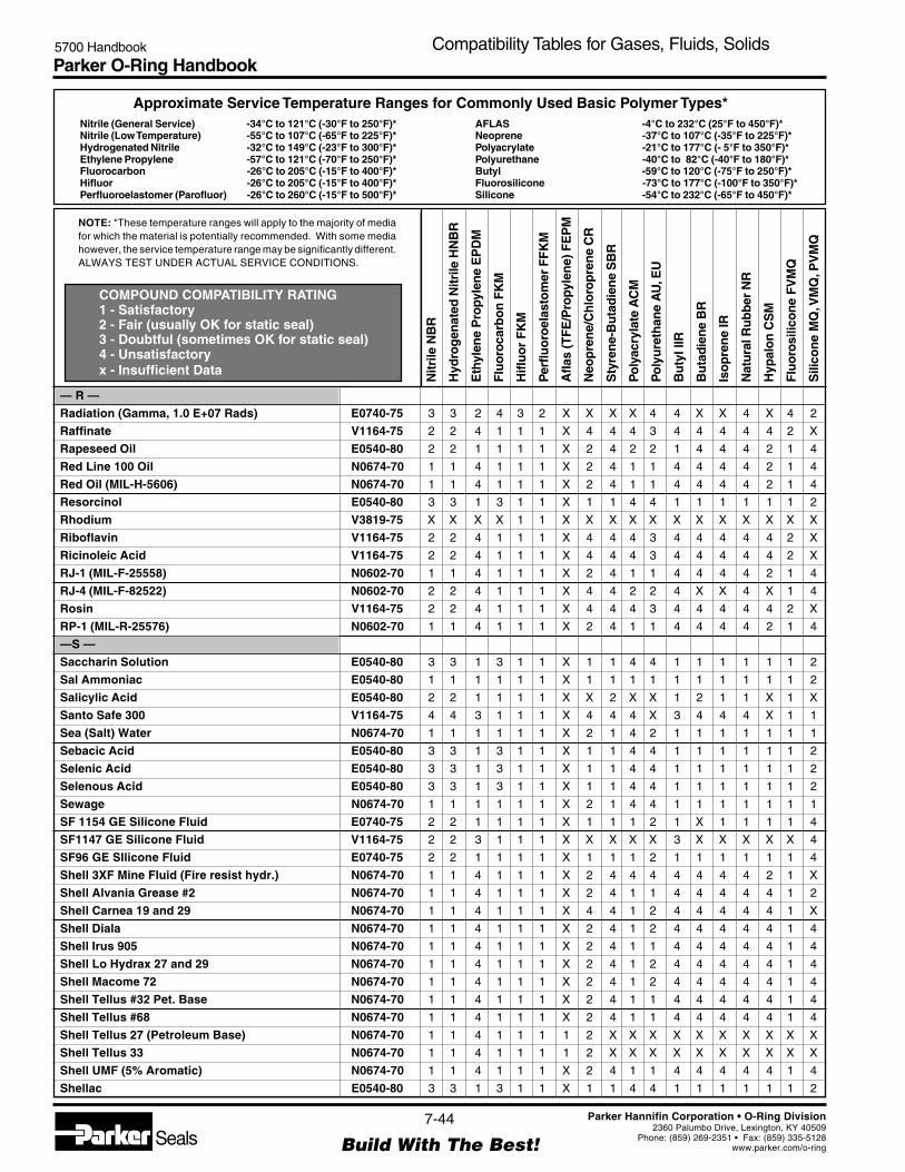
Parker O-Ring Handbook5700 Handbook Compatibility Tables for Gases, Fluids, Solids
NOTE: *These temperature ranges will apply to the majority of mediafor which the material is potentially recommended. With some mediahowever, the service temperature range may be significantly different.ALWAYS TEST UNDER ACTUAL SERVICE CONDITIONS.
Nitrile (General Service) -34°C to 121°C (-30°F to 250°F)*Nitrile (Low Temperature) -55°C to 107°C (-65°F to 225°F)*Hydrogenated Nitrile -32°C to 149°C (-23°F to 300°F)*Ethylene Propylene -57°C to 121°C (-70°F to 250°F)*Fluorocarbon -26°C to 205°C (-15°F to 400°F)*Hifluor -26°C to 205°C (-15°F to 400°F)*Perfluoroelastomer (Parofluor) -26°C to 260°C (-15°F to 500°F)*
Approximate Service Temperature Ranges for Commonly Used Basic Polymer Types*
COMPOUND COMPATIBILITY RATING1 - Satisfactory2 - Fair (usually OK for static seal)3 - Doubtful (sometimes OK for static seal)4 - Unsatisfactoryx - Insufficient Data
AFLAS -4°C to 232°C (25°F to 450°F)*Neoprene -37°C to 107°C (-35°F to 225°F)*Polyacrylate -21°C to 177°C (- 5°F to 350°F)*Polyurethane -40°C to 82°C (-40°F to 180°F)*Butyl -59°C to 120°C (-75°F to 250°F)*Fluorosilicone -73°C to 177°C (-100°F to 350°F)*Silicone -54°C to 232°C (-65°F to 450°F)*
Nitr
ile N
BR
Hyd
rog
enat
ed N
itrile
HN
BR
Eth
ylen
e P
ropy
len
e E
PD
M
Flu
oro
carb
on
FK
M
Hifl
uo
r F
KM
Per
fluo
roel
asto
mer
FF
KM
Afla
s (T
FE
/Pro
pyle
ne)
FE
PM
Neo
pre
ne/
Ch
loro
pre
ne
CR
Sty
ren
e-B
uta
die
ne
SB
R
Po
lyac
ryla
te A
CM
Po
lyu
reth
ane
AU
, EU
Bu
tyl I
IR
Bu
tad
ien
e B
R
Iso
pre
ne
IR
Nat
ura
l Ru
bb
er N
R
Hyp
alo
n C
SM
Flu
oro
silic
on
e F
VM
Q
Sili
con
e M
Q, V
MQ
, PV
MQ
7-44
Build With The Best!SealsParker Hannifin Corporation • O-Ring Division
2360 Palumbo Drive, Lexington, KY 40509Phone: (859) 269-2351 • Fax: (859) 335-5128
www.parker.com/o-ring
— R —
Radiation (Gamma, 1.0 E+07 Rads) E0740-75 3 3 2 4 3 2 X X X X 4 4 X X 4 X 4 2
Raffinate V1164-75 2 2 4 1 1 1 X 4 4 4 3 4 4 4 4 4 2 X
Rapeseed Oil E0540-80 2 2 1 1 1 1 X 2 4 2 2 1 4 4 4 2 1 4
Red Line 100 Oil N0674-70 1 1 4 1 1 1 X 2 4 1 1 4 4 4 4 2 1 4
Red Oil (MIL-H-5606) N0674-70 1 1 4 1 1 1 X 2 4 1 1 4 4 4 4 2 1 4
Resorcinol E0540-80 3 3 1 3 1 1 X 1 1 4 4 1 1 1 1 1 1 2
Rhodium V3819-75 X X X X 1 1 X X X X X X X X X X X X
Riboflavin V1164-75 2 2 4 1 1 1 X 4 4 4 3 4 4 4 4 4 2 X
Ricinoleic Acid V1164-75 2 2 4 1 1 1 X 4 4 4 3 4 4 4 4 4 2 X
RJ-1 (MIL-F-25558) N0602-70 1 1 4 1 1 1 X 2 4 1 1 4 4 4 4 2 1 4
RJ-4 (MIL-F-82522) N0602-70 2 2 4 1 1 1 X 4 4 2 2 4 X X 4 X 1 4
Rosin V1164-75 2 2 4 1 1 1 X 4 4 4 3 4 4 4 4 4 2 X
RP-1 (MIL-R-25576) N0602-70 1 1 4 1 1 1 X 2 4 1 1 4 4 4 4 2 1 4
—S —
Saccharin Solution E0540-80 3 3 1 3 1 1 X 1 1 4 4 1 1 1 1 1 1 2
Sal Ammoniac E0540-80 1 1 1 1 1 1 X 1 1 1 1 1 1 1 1 1 1 2
Salicylic Acid E0540-80 2 2 1 1 1 1 X X 2 X X 1 2 1 1 X 1 X
Santo Safe 300 V1164-75 4 4 3 1 1 1 X 4 4 4 X 3 4 4 4 X 1 1
Sea (Salt) Water N0674-70 1 1 1 1 1 1 X 2 1 4 2 1 1 1 1 1 1 1
Sebacic Acid E0540-80 3 3 1 3 1 1 X 1 1 4 4 1 1 1 1 1 1 2
Selenic Acid E0540-80 3 3 1 3 1 1 X 1 1 4 4 1 1 1 1 1 1 2
Selenous Acid E0540-80 3 3 1 3 1 1 X 1 1 4 4 1 1 1 1 1 1 2
Sewage N0674-70 1 1 1 1 1 1 X 2 1 4 4 1 1 1 1 1 1 1
SF 1154 GE Silicone Fluid E0740-75 2 2 1 1 1 1 X 1 1 1 2 1 X 1 1 1 1 4
SF1147 GE Silicone Fluid V1164-75 2 2 3 1 1 1 X X X X X 3 X X X X X 4
SF96 GE SIlicone Fluid E0740-75 2 2 1 1 1 1 X 1 1 1 2 1 1 1 1 1 1 4
Shell 3XF Mine Fluid (Fire resist hydr.) N0674-70 1 1 4 1 1 1 X 2 4 4 4 4 4 4 4 2 1 X
Shell Alvania Grease #2 N0674-70 1 1 4 1 1 1 X 2 4 1 1 4 4 4 4 4 1 2
Shell Carnea 19 and 29 N0674-70 1 1 4 1 1 1 X 4 4 1 2 4 4 4 4 4 1 X
Shell Diala N0674-70 1 1 4 1 1 1 X 2 4 1 2 4 4 4 4 4 1 4
Shell Irus 905 N0674-70 1 1 4 1 1 1 X 2 4 1 1 4 4 4 4 4 1 4
Shell Lo Hydrax 27 and 29 N0674-70 1 1 4 1 1 1 X 2 4 1 2 4 4 4 4 4 1 4
Shell Macome 72 N0674-70 1 1 4 1 1 1 X 2 4 1 2 4 4 4 4 4 1 4
Shell Tellus #32 Pet. Base N0674-70 1 1 4 1 1 1 X 2 4 1 1 4 4 4 4 4 1 4
Shell Tellus #68 N0674-70 1 1 4 1 1 1 X 2 4 1 1 4 4 4 4 4 1 4
Shell Tellus 27 (Petroleum Base) N0674-70 1 1 4 1 1 1 1 2 X X X X X X X X X X
Shell Tellus 33 N0674-70 1 1 4 1 1 1 1 2 X X X X X X X X X X
Shell UMF (5% Aromatic) N0674-70 1 1 4 1 1 1 X 2 4 1 1 4 4 4 4 4 1 4
Shellac E0540-80 3 3 1 3 1 1 X 1 1 4 4 1 1 1 1 1 1 2
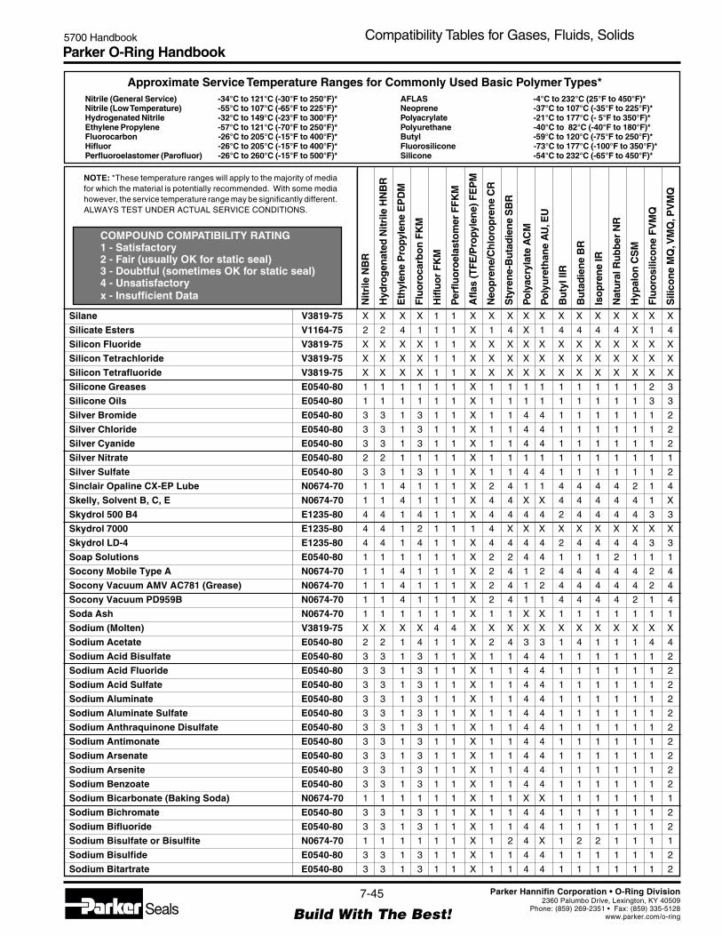
Parker O-Ring Handbook5700 Handbook Compatibility Tables for Gases, Fluids, Solids
NOTE: *These temperature ranges will apply to the majority of mediafor which the material is potentially recommended. With some mediahowever, the service temperature range may be significantly different.ALWAYS TEST UNDER ACTUAL SERVICE CONDITIONS.
Nitrile (General Service) -34°C to 121°C (-30°F to 250°F)*Nitrile (Low Temperature) -55°C to 107°C (-65°F to 225°F)*Hydrogenated Nitrile -32°C to 149°C (-23°F to 300°F)*Ethylene Propylene -57°C to 121°C (-70°F to 250°F)*Fluorocarbon -26°C to 205°C (-15°F to 400°F)*Hifluor -26°C to 205°C (-15°F to 400°F)*Perfluoroelastomer (Parofluor) -26°C to 260°C (-15°F to 500°F)*
Approximate Service Temperature Ranges for Commonly Used Basic Polymer Types*
COMPOUND COMPATIBILITY RATING1 - Satisfactory2 - Fair (usually OK for static seal)3 - Doubtful (sometimes OK for static seal)4 - Unsatisfactoryx - Insufficient Data
AFLAS -4°C to 232°C (25°F to 450°F)*Neoprene -37°C to 107°C (-35°F to 225°F)*Polyacrylate -21°C to 177°C (- 5°F to 350°F)*Polyurethane -40°C to 82°C (-40°F to 180°F)*Butyl -59°C to 120°C (-75°F to 250°F)*Fluorosilicone -73°C to 177°C (-100°F to 350°F)*Silicone -54°C to 232°C (-65°F to 450°F)*
Nitr
ile N
BR
Hyd
rog
enat
ed N
itrile
HN
BR
Eth
ylen
e P
ropy
len
e E
PD
M
Flu
oro
carb
on
FK
M
Hifl
uo
r F
KM
Per
fluo
roel
asto
mer
FF
KM
Afla
s (T
FE
/Pro
pyle
ne)
FE
PM
Neo
pre
ne/
Ch
loro
pre
ne
CR
Sty
ren
e-B
uta
die
ne
SB
R
Po
lyac
ryla
te A
CM
Po
lyu
reth
ane
AU
, EU
Bu
tyl I
IR
Bu
tad
ien
e B
R
Iso
pre
ne
IR
Nat
ura
l Ru
bb
er N
R
Hyp
alo
n C
SM
Flu
oro
silic
on
e F
VM
Q
Sili
con
e M
Q, V
MQ
, PV
MQ
7-45
Build With The Best!SealsParker Hannifin Corporation • O-Ring Division
2360 Palumbo Drive, Lexington, KY 40509Phone: (859) 269-2351 • Fax: (859) 335-5128
www.parker.com/o-ring
Silane V3819-75 X X X X 1 1 X X X X X X X X X X X X
Silicate Esters V1164-75 2 2 4 1 1 1 X 1 4 X 1 4 4 4 4 X 1 4
Silicon Fluoride V3819-75 X X X X 1 1 X X X X X X X X X X X X
Silicon Tetrachloride V3819-75 X X X X 1 1 X X X X X X X X X X X X
Silicon Tetrafluoride V3819-75 X X X X 1 1 X X X X X X X X X X X X
Silicone Greases E0540-80 1 1 1 1 1 1 X 1 1 1 1 1 1 1 1 1 2 3
Silicone Oils E0540-80 1 1 1 1 1 1 X 1 1 1 1 1 1 1 1 1 3 3
Silver Bromide E0540-80 3 3 1 3 1 1 X 1 1 4 4 1 1 1 1 1 1 2
Silver Chloride E0540-80 3 3 1 3 1 1 X 1 1 4 4 1 1 1 1 1 1 2
Silver Cyanide E0540-80 3 3 1 3 1 1 X 1 1 4 4 1 1 1 1 1 1 2
Silver Nitrate E0540-80 2 2 1 1 1 1 X 1 1 1 1 1 1 1 1 1 1 1
Silver Sulfate E0540-80 3 3 1 3 1 1 X 1 1 4 4 1 1 1 1 1 1 2
Sinclair Opaline CX-EP Lube N0674-70 1 1 4 1 1 1 X 2 4 1 1 4 4 4 4 2 1 4
Skelly, Solvent B, C, E N0674-70 1 1 4 1 1 1 X 4 4 X X 4 4 4 4 4 1 X
Skydrol 500 B4 E1235-80 4 4 1 4 1 1 X 4 4 4 4 2 4 4 4 4 3 3
Skydrol 7000 E1235-80 4 4 1 2 1 1 1 4 X X X X X X X X X X
Skydrol LD-4 E1235-80 4 4 1 4 1 1 X 4 4 4 4 2 4 4 4 4 3 3
Soap Solutions E0540-80 1 1 1 1 1 1 X 2 2 4 4 1 1 1 2 1 1 1
Socony Mobile Type A N0674-70 1 1 4 1 1 1 X 2 4 1 2 4 4 4 4 4 2 4
Socony Vacuum AMV AC781 (Grease) N0674-70 1 1 4 1 1 1 X 2 4 1 2 4 4 4 4 4 2 4
Socony Vacuum PD959B N0674-70 1 1 4 1 1 1 X 2 4 1 1 4 4 4 4 2 1 4
Soda Ash N0674-70 1 1 1 1 1 1 X 1 1 X X 1 1 1 1 1 1 1
Sodium (Molten) V3819-75 X X X X 4 4 X X X X X X X X X X X X
Sodium Acetate E0540-80 2 2 1 4 1 1 X 2 4 3 3 1 4 1 1 1 4 4
Sodium Acid Bisulfate E0540-80 3 3 1 3 1 1 X 1 1 4 4 1 1 1 1 1 1 2
Sodium Acid Fluoride E0540-80 3 3 1 3 1 1 X 1 1 4 4 1 1 1 1 1 1 2
Sodium Acid Sulfate E0540-80 3 3 1 3 1 1 X 1 1 4 4 1 1 1 1 1 1 2
Sodium Aluminate E0540-80 3 3 1 3 1 1 X 1 1 4 4 1 1 1 1 1 1 2
Sodium Aluminate Sulfate E0540-80 3 3 1 3 1 1 X 1 1 4 4 1 1 1 1 1 1 2
Sodium Anthraquinone Disulfate E0540-80 3 3 1 3 1 1 X 1 1 4 4 1 1 1 1 1 1 2
Sodium Antimonate E0540-80 3 3 1 3 1 1 X 1 1 4 4 1 1 1 1 1 1 2
Sodium Arsenate E0540-80 3 3 1 3 1 1 X 1 1 4 4 1 1 1 1 1 1 2
Sodium Arsenite E0540-80 3 3 1 3 1 1 X 1 1 4 4 1 1 1 1 1 1 2
Sodium Benzoate E0540-80 3 3 1 3 1 1 X 1 1 4 4 1 1 1 1 1 1 2
Sodium Bicarbonate (Baking Soda) N0674-70 1 1 1 1 1 1 X 1 1 X X 1 1 1 1 1 1 1
Sodium Bichromate E0540-80 3 3 1 3 1 1 X 1 1 4 4 1 1 1 1 1 1 2
Sodium Bifluoride E0540-80 3 3 1 3 1 1 X 1 1 4 4 1 1 1 1 1 1 2
Sodium Bisulfate or Bisulfite N0674-70 1 1 1 1 1 1 X 1 2 4 X 1 2 2 1 1 1 1
Sodium Bisulfide E0540-80 3 3 1 3 1 1 X 1 1 4 4 1 1 1 1 1 1 2
Sodium Bitartrate E0540-80 3 3 1 3 1 1 X 1 1 4 4 1 1 1 1 1 1 2

Parker O-Ring Handbook5700 Handbook Compatibility Tables for Gases, Fluids, Solids
NOTE: *These temperature ranges will apply to the majority of mediafor which the material is potentially recommended. With some mediahowever, the service temperature range may be significantly different.ALWAYS TEST UNDER ACTUAL SERVICE CONDITIONS.
Nitrile (General Service) -34°C to 121°C (-30°F to 250°F)*Nitrile (Low Temperature) -55°C to 107°C (-65°F to 225°F)*Hydrogenated Nitrile -32°C to 149°C (-23°F to 300°F)*Ethylene Propylene -57°C to 121°C (-70°F to 250°F)*Fluorocarbon -26°C to 205°C (-15°F to 400°F)*Hifluor -26°C to 205°C (-15°F to 400°F)*Perfluoroelastomer (Parofluor) -26°C to 260°C (-15°F to 500°F)*
Approximate Service Temperature Ranges for Commonly Used Basic Polymer Types*
COMPOUND COMPATIBILITY RATING1 - Satisfactory2 - Fair (usually OK for static seal)3 - Doubtful (sometimes OK for static seal)4 - Unsatisfactoryx - Insufficient Data
AFLAS -4°C to 232°C (25°F to 450°F)*Neoprene -37°C to 107°C (-35°F to 225°F)*Polyacrylate -21°C to 177°C (- 5°F to 350°F)*Polyurethane -40°C to 82°C (-40°F to 180°F)*Butyl -59°C to 120°C (-75°F to 250°F)*Fluorosilicone -73°C to 177°C (-100°F to 350°F)*Silicone -54°C to 232°C (-65°F to 450°F)*
Nitr
ile N
BR
Hyd
rog
enat
ed N
itrile
HN
BR
Eth
ylen
e P
ropy
len
e E
PD
M
Flu
oro
carb
on
FK
M
Hifl
uo
r F
KM
Per
fluo
roel
asto
mer
FF
KM
Afla
s (T
FE
/Pro
pyle
ne)
FE
PM
Neo
pre
ne/
Ch
loro
pre
ne
CR
Sty
ren
e-B
uta
die
ne
SB
R
Po
lyac
ryla
te A
CM
Po
lyu
reth
ane
AU
, EU
Bu
tyl I
IR
Bu
tad
ien
e B
R
Iso
pre
ne
IR
Nat
ura
l Ru
bb
er N
R
Hyp
alo
n C
SM
Flu
oro
silic
on
e F
VM
Q
Sili
con
e M
Q, V
MQ
, PV
MQ
7-46
Build With The Best!SealsParker Hannifin Corporation • O-Ring Division
2360 Palumbo Drive, Lexington, KY 40509Phone: (859) 269-2351 • Fax: (859) 335-5128
www.parker.com/o-ring
Sodium Borate N0674-70 1 1 1 1 1 1 X 1 1 X X 1 1 1 1 1 1 1
Sodium Bromate E0540-80 3 3 1 3 1 1 X 1 1 4 4 1 1 1 1 1 1 2
Sodium Bromide E0540-80 3 3 1 3 1 1 X 1 1 4 4 1 1 1 1 1 1 2
Sodium Carbonate (Soda Ash) N0674-70 1 1 1 1 1 1 X 1 1 X X 1 1 1 1 1 1 1
Sodium Chlorate E0540-80 3 3 1 3 1 1 X 1 1 4 4 1 1 1 1 1 1 2
Sodium Chloride N0674-70 1 1 1 1 1 1 X 1 1 X 1 1 1 1 1 1 X 1
Sodium Chlorite E0540-80 3 3 1 3 1 1 X 1 1 4 4 1 1 1 1 1 1 2
Sodium Chloroacetate E0540-80 3 3 1 3 1 1 X 1 1 4 4 1 1 1 1 1 1 2
Sodium Chromate E0540-80 3 3 1 3 1 1 X 1 1 4 4 1 1 1 1 1 1 2
Sodium Citrate E0540-80 3 3 1 3 1 1 X 1 1 4 4 1 1 1 1 1 1 2
Sodium Cyanamide E0540-80 3 3 1 3 1 1 X 1 1 4 4 1 1 1 1 1 1 2
Sodium Cyanate E0540-80 3 3 1 3 1 1 X 1 1 4 4 1 1 1 1 1 1 2
Sodium Cyanide N0674-70 1 1 1 X 1 1 X 1 1 X X 1 1 1 1 1 X 1
Sodium Diacetate E0540-80 3 3 1 3 1 1 X 1 1 4 4 1 1 1 1 1 1 2
Sodium Diphenyl Sulfonate E0540-80 3 3 1 3 1 1 X 1 1 4 4 1 1 1 1 1 1 2
Sodium Diphosphate E0540-80 3 3 1 3 1 1 X 1 1 4 4 1 1 1 1 1 1 2
Sodium Disilicate E0540-80 3 3 1 3 1 1 X 1 1 4 4 1 1 1 1 1 1 2
Sodium Ethylate E0540-80 3 3 1 3 1 1 X 1 1 4 4 1 1 1 1 1 1 2
Sodium Ferricyanide E0540-80 3 3 1 3 1 1 X 1 1 4 4 1 1 1 1 1 1 2
Sodium Ferrocyanide E0540-80 3 3 1 3 1 1 X 1 1 4 4 1 1 1 1 1 1 2
Sodium Fluoride E0540-80 3 3 1 3 1 1 X 1 1 4 4 1 1 1 1 1 1 2
Sodium Fluorosilicate E0540-80 3 3 1 3 1 1 X 1 1 4 4 1 1 1 1 1 1 2
Sodium Glutamate E0540-80 3 3 1 3 1 1 X 1 1 4 4 1 1 1 1 1 1 2
Sodium Hydride V3819-75 X X X X 1 1 X X X X X X X X X X X X
Sodium Hydrogen Sulfate E0540-80 3 3 1 3 1 1 X 1 1 4 4 1 1 1 1 1 1 2
Sodium Hydrosulfide E0540-80 3 3 1 3 1 1 X 1 1 4 4 1 1 1 1 1 1 2
Sodium Hydrosulfite E0540-80 3 3 1 3 1 1 X 1 1 4 4 1 1 1 1 1 1 2
Sodium Hydroxide, 3 Molar E0540-80 2 2 1 2 1 1 X 2 2 4 2 1 1 1 1 1 2 1
Sodium Hypochlorite E0540-80 2 2 1 1 1 1 X 2 2 4 4 1 2 2 2 1 2 2
Sodium Hypophosphate E0540-80 3 3 1 3 1 1 X 1 1 4 4 1 1 1 1 1 1 2
Sodium Hypophosphite E0540-80 3 3 1 3 1 1 X 1 1 4 4 1 1 1 1 1 1 2
Sodium Hyposulfite E0540-80 3 3 1 3 1 1 X 1 1 4 4 1 1 1 1 1 1 2
Sodium Iodide E0540-80 3 3 1 3 1 1 X 1 1 4 4 1 1 1 1 1 1 2
Sodium Lactate E0540-80 3 3 1 3 1 1 X 1 1 4 4 1 1 1 1 1 1 2
Sodium Metaphosphate N0674-70 1 1 1 1 1 1 X 2 1 X X 1 1 1 1 2 1 X
Sodium Metasilicate E0540-80 3 3 1 3 1 1 X 1 1 4 4 1 1 1 1 1 1 2
Sodium Methylate E0540-80 3 3 1 3 1 1 X 1 1 4 4 1 1 1 1 1 1 2
Sodium Monophosphate E0540-80 3 3 1 3 1 1 X 1 1 4 4 1 1 1 1 1 1 2
Sodium Nitrate E0540-80 2 2 1 X 1 1 X 2 2 X X 1 1 1 2 1 X 4
Sodium Oleate E0540-80 3 3 1 3 1 1 X 1 1 4 4 1 1 1 1 1 1 2

Parker O-Ring Handbook5700 Handbook Compatibility Tables for Gases, Fluids, Solids
NOTE: *These temperature ranges will apply to the majority of mediafor which the material is potentially recommended. With some mediahowever, the service temperature range may be significantly different.ALWAYS TEST UNDER ACTUAL SERVICE CONDITIONS.
Nitrile (General Service) -34°C to 121°C (-30°F to 250°F)*Nitrile (Low Temperature) -55°C to 107°C (-65°F to 225°F)*Hydrogenated Nitrile -32°C to 149°C (-23°F to 300°F)*Ethylene Propylene -57°C to 121°C (-70°F to 250°F)*Fluorocarbon -26°C to 205°C (-15°F to 400°F)*Hifluor -26°C to 205°C (-15°F to 400°F)*Perfluoroelastomer (Parofluor) -26°C to 260°C (-15°F to 500°F)*
Approximate Service Temperature Ranges for Commonly Used Basic Polymer Types*
COMPOUND COMPATIBILITY RATING1 - Satisfactory2 - Fair (usually OK for static seal)3 - Doubtful (sometimes OK for static seal)4 - Unsatisfactoryx - Insufficient Data
AFLAS -4°C to 232°C (25°F to 450°F)*Neoprene -37°C to 107°C (-35°F to 225°F)*Polyacrylate -21°C to 177°C (- 5°F to 350°F)*Polyurethane -40°C to 82°C (-40°F to 180°F)*Butyl -59°C to 120°C (-75°F to 250°F)*Fluorosilicone -73°C to 177°C (-100°F to 350°F)*Silicone -54°C to 232°C (-65°F to 450°F)*
Nitr
ile N
BR
Hyd
rog
enat
ed N
itrile
HN
BR
Eth
ylen
e P
ropy
len
e E
PD
M
Flu
oro
carb
on
FK
M
Hifl
uo
r F
KM
Per
fluo
roel
asto
mer
FF
KM
Afla
s (T
FE
/Pro
pyle
ne)
FE
PM
Neo
pre
ne/
Ch
loro
pre
ne
CR
Sty
ren
e-B
uta
die
ne
SB
R
Po
lyac
ryla
te A
CM
Po
lyu
reth
ane
AU
, EU
Bu
tyl I
IR
Bu
tad
ien
e B
R
Iso
pre
ne
IR
Nat
ura
l Ru
bb
er N
R
Hyp
alo
n C
SM
Flu
oro
silic
on
e F
VM
Q
Sili
con
e M
Q, V
MQ
, PV
MQ
7-47
Build With The Best!SealsParker Hannifin Corporation • O-Ring Division
2360 Palumbo Drive, Lexington, KY 40509Phone: (859) 269-2351 • Fax: (859) 335-5128
www.parker.com/o-ring
Sodium Orthosilicate E0540-80 3 3 1 3 1 1 X 1 1 4 4 1 1 1 1 1 1 2
Sodium Oxalate E0540-80 3 3 1 3 1 1 X 1 1 4 4 1 1 1 1 1 1 2
Sodium Perborate E0540-80 2 2 1 1 1 1 X 2 2 X X 1 2 2 2 2 1 2
Sodium Percarbonate E0540-80 3 3 1 3 1 1 X 1 1 4 4 1 1 1 1 1 1 2
Sodium Perchlorate E0540-80 3 3 1 3 1 1 X 1 1 4 4 1 1 1 1 1 1 2
Sodium Peroxide E0540-80 2 2 1 1 1 1 X 2 2 4 4 1 2 2 2 2 1 4
Sodium Persulfate E0540-80 3 3 1 3 1 1 X 1 1 4 4 1 1 1 1 1 1 2
Sodium Phenolate E0540-80 3 3 1 3 1 1 X 1 1 4 4 1 1 1 1 1 1 2
Sodium Phenoxide E0540-80 3 3 1 3 1 1 X 1 1 4 4 1 1 1 1 1 1 2
Sodium Phosphate (Dibasic) N0674-70 1 1 1 1 1 1 X 2 1 1 1 1 1 1 1 1 X 4
Sodium Phosphate (Mono) N0674-70 1 1 1 1 1 1 X 2 1 1 1 1 1 1 1 1 X 4
Sodium Phosphate (Tribasic) N0674-70 1 1 1 1 1 1 X 2 1 1 1 1 1 1 1 1 X 1
Sodium Plumbite E0540-80 3 3 1 3 1 1 X 1 1 4 4 1 1 1 1 1 1 2
Sodium Pyrophosphate E0540-80 3 3 1 3 1 1 X 1 1 4 4 1 1 1 1 1 1 2
Sodium Resinate E0540-80 3 3 1 3 1 1 X 1 1 4 4 1 1 1 1 1 1 2
Sodium Salicylate E0540-80 3 3 1 3 1 1 X 1 1 4 4 1 1 1 1 1 1 2
Sodium Salts N0674-70 1 1 1 1 1 1 X 2 1 1 1 1 1 1 1 1 1 1
Sodium Sesquisilicate V3819-75 X X X X 1 1 X X X X X X X X X X X X
Sodium Silicate N0674-70 1 1 1 1 1 1 X 1 1 X X 1 1 1 1 1 X X
Sodium Silicofluoride V3819-75 X X X X 1 1 X X X X X X X X X X X X
Sodium Stannate E0540-80 3 3 1 3 1 1 X 1 1 4 4 1 1 1 1 1 1 2
Sodium Sulfate N0674-70 1 1 1 1 1 1 X 1 2 4 1 1 2 2 2 1 1 1
Sodium Sulfide and Sulfite N0674-70 1 1 1 1 1 1 X 1 2 4 1 1 2 2 2 1 1 1
Sodium Sulfocyanide E0540-80 3 3 1 3 1 1 X 1 1 4 4 1 1 1 1 1 1 2
Sodium Tartrate E0540-80 3 3 1 3 1 1 X 1 1 4 4 1 1 1 1 1 1 2
Sodium Tetraborate E0540-80 3 3 1 3 1 1 X 1 1 4 4 1 1 1 1 1 1 2
Sodium Tetraphosphate E0540-80 3 3 1 3 1 1 X 1 1 4 4 1 1 1 1 1 1 2
Sodium Tetrasulfide E0540-80 3 3 1 3 1 1 X 1 1 4 4 1 1 1 1 1 1 2
Sodium Thioarsenate E0540-80 3 3 1 3 1 1 X 1 1 4 4 1 1 1 1 1 1 2
Sodium Thiocyanate E0540-80 3 3 1 3 1 1 X 1 1 4 4 1 1 1 1 1 1 2
Sodium Thiosulfate E0540-80 2 2 1 1 1 1 X 1 2 4 1 1 2 2 2 1 1 1
Sodium Trichloroacetate E0540-80 3 3 1 3 1 1 X 1 1 4 4 1 1 1 1 1 1 2
Sodium Triphosphate E0540-80 3 3 1 3 1 1 X 1 1 4 4 1 1 1 1 1 1 2
Solvesso 100, 150 V3819-75 X X X X 1 1 X X X X X X X X X X X X
Sorbitol E0540-80 3 3 1 3 1 1 X 1 1 4 4 1 1 1 1 1 1 2
Sour Crude Oil V1238-95 3 3 4 1 1 1 X 4 4 4 4 4 4 4 4 X 4 4
Sour Natural Gas V1238-95 3 3 4 1 1 1 X 4 4 4 4 4 4 4 4 X 4 4
Sovasol No. 1, 2, and 3 N0674-70 1 1 4 1 1 1 X 2 4 2 2 4 4 4 4 2 1 4
Sovasol No. 73 and 74 V1164-75 2 2 4 1 1 1 X 2 4 2 2 4 4 4 4 2 1 4
Soybean Oil N0674-70 1 1 3 1 1 1 X 3 4 1 X 3 4 4 4 3 1 1

Parker O-Ring Handbook5700 Handbook Compatibility Tables for Gases, Fluids, Solids
NOTE: *These temperature ranges will apply to the majority of mediafor which the material is potentially recommended. With some mediahowever, the service temperature range may be significantly different.ALWAYS TEST UNDER ACTUAL SERVICE CONDITIONS.
Nitrile (General Service) -34°C to 121°C (-30°F to 250°F)*Nitrile (Low Temperature) -55°C to 107°C (-65°F to 225°F)*Hydrogenated Nitrile -32°C to 149°C (-23°F to 300°F)*Ethylene Propylene -57°C to 121°C (-70°F to 250°F)*Fluorocarbon -26°C to 205°C (-15°F to 400°F)*Hifluor -26°C to 205°C (-15°F to 400°F)*Perfluoroelastomer (Parofluor) -26°C to 260°C (-15°F to 500°F)*
Approximate Service Temperature Ranges for Commonly Used Basic Polymer Types*
COMPOUND COMPATIBILITY RATING1 - Satisfactory2 - Fair (usually OK for static seal)3 - Doubtful (sometimes OK for static seal)4 - Unsatisfactoryx - Insufficient Data
AFLAS -4°C to 232°C (25°F to 450°F)*Neoprene -37°C to 107°C (-35°F to 225°F)*Polyacrylate -21°C to 177°C (- 5°F to 350°F)*Polyurethane -40°C to 82°C (-40°F to 180°F)*Butyl -59°C to 120°C (-75°F to 250°F)*Fluorosilicone -73°C to 177°C (-100°F to 350°F)*Silicone -54°C to 232°C (-65°F to 450°F)*
Nitr
ile N
BR
Hyd
rog
enat
ed N
itrile
HN
BR
Eth
ylen
e P
ropy
len
e E
PD
M
Flu
oro
carb
on
FK
M
Hifl
uo
r F
KM
Per
fluo
roel
asto
mer
FF
KM
Afla
s (T
FE
/Pro
pyle
ne)
FE
PM
Neo
pre
ne/
Ch
loro
pre
ne
CR
Sty
ren
e-B
uta
die
ne
SB
R
Po
lyac
ryla
te A
CM
Po
lyu
reth
ane
AU
, EU
Bu
tyl I
IR
Bu
tad
ien
e B
R
Iso
pre
ne
IR
Nat
ura
l Ru
bb
er N
R
Hyp
alo
n C
SM
Flu
oro
silic
on
e F
VM
Q
Sili
con
e M
Q, V
MQ
, PV
MQ
7-48
Build With The Best!SealsParker Hannifin Corporation • O-Ring Division
2360 Palumbo Drive, Lexington, KY 40509Phone: (859) 269-2351 • Fax: (859) 335-5128
www.parker.com/o-ring
Spry N0674-70 1 1 2 1 1 1 X 2 4 1 1 2 4 4 4 4 1 1
SR-10 Fuel N0674-70 1 1 4 1 1 1 X 4 4 2 2 4 4 4 4 4 1 4
SR-6 Fuel V1164-75 2 2 4 1 1 1 X 4 4 2 2 4 4 4 4 4 1 4
Standard Oil Mobilube GX90-EP Lube N0674-70 1 1 4 1 1 1 X 2 4 1 1 4 4 4 4 2 1 4
Stannic Ammonium Chloride E0540-80 3 3 1 3 1 1 X 1 1 4 4 1 1 1 1 1 1 2
Stannic Chloride N0674-70 1 1 1 1 1 1 X 4 1 X X 1 1 1 1 4 1 2
Stannic Chloride, 50% N0674-70 1 1 1 1 1 1 X 4 1 X X 1 1 1 1 4 1 2
Stannic Tetrachloride E0540-80 3 3 1 3 1 1 X 1 1 4 4 1 1 1 1 1 1 2
Stannous Bisulfate E0540-80 3 3 1 3 1 1 X 1 1 4 4 1 1 1 1 1 1 2
Stannous Bromide E0540-80 3 3 1 3 1 1 X 1 1 4 4 1 1 1 1 1 1 2
Stannous Chloride (15%) N0674-70 1 1 1 1 1 1 X 1 1 X X 1 1 1 1 1 1 2
Stannous Fluoride E0540-80 3 3 1 3 1 1 X 1 1 4 4 1 1 1 1 1 1 2
Stannous Sulfate E0540-80 3 3 1 3 1 1 X 1 1 4 4 1 1 1 1 1 1 2
Stauffer 7700 V1164-75 2 2 4 1 1 1 X 4 4 2 X 4 4 4 4 4 2 4
Steam Below 400°F E0692-75 4 4 1 4 1 1 X 4 4 4 4 2 4 4 4 4 4 3
Steam, 400° - 500°F E0962-90 4 4 3 4 1 1 X 4 4 4 4 4 4 4 4 4 4 4
Steam, Above 500°F V8545-75 X X X X 1 1 X X X X X X X X X X X X
Stearic Acid N0674-70 2 2 2 X 1 1 X 2 2 X X 2 2 2 2 2 X 2
Stoddard Solvent N0674-70 1 1 4 1 1 1 X 2 4 1 1 4 4 4 4 4 1 4
Strontium Acetate E0540-80 3 3 1 3 1 1 X 1 1 4 4 1 1 1 1 1 1 2
Strontium Carbonate E0540-80 3 3 1 3 1 1 X 1 1 4 4 1 1 1 1 1 1 2
Strontium Chloride E0540-80 3 3 1 3 1 1 X 1 1 4 4 1 1 1 1 1 1 2
Strontium Hydroxide E0540-80 3 3 1 3 1 1 X 1 1 4 4 1 1 1 1 1 1 2
Strontium Nitrate E0540-80 3 3 1 3 1 1 X 1 1 4 4 1 1 1 1 1 1 2
Styrene (Monomer) V1164-75 4 4 4 2 1 1 X 4 4 4 X 4 4 4 4 4 3 4
Succinic Acid E0540-80 3 3 1 3 1 1 X 1 1 4 4 1 1 1 1 1 1 2
Sucrose Solutions N0674-70 1 1 1 1 1 1 X 2 1 4 4 1 1 1 1 2 1 1
Sulfamic Acid E0540-80 3 3 1 3 1 1 X 1 1 4 4 1 1 1 1 1 1 2
Sulfanilic Acid E0540-80 3 3 1 3 1 1 X 1 1 4 4 1 1 1 1 1 1 2
Sulfanilic Chloride V1164-75 2 2 4 1 1 1 X 4 4 4 3 4 4 4 4 4 2 X
Sulfanilimide V1164-75 2 2 4 1 1 1 X 4 4 4 3 4 4 4 4 4 2 X
Sulfite Liquors E0540-80 3 3 1 3 1 1 X 1 1 4 4 1 1 1 1 1 1 2
Sulfolane E0540-80 2 2 1 2 1 1 1 2 X X X X X X X X X X
Sulfonated Oils V1164-75 2 2 4 1 1 1 X 4 4 4 3 4 4 4 4 4 2 X
Sulfonic Acid E0540-80 3 3 1 3 1 1 X 1 1 4 4 1 1 1 1 1 1 2
Sulfonyl Choride E0540-80 3 3 1 3 2 2 X 1 1 4 4 1 1 1 1 1 1 2
Sulfur E0540-80 4 4 1 1 1 1 X 1 4 4 X 1 4 4 4 X 1 X
Sulfur (Molten) V1164-75 4 4 3 1 1 1 X 3 4 4 4 3 4 4 4 4 3 3
Sulfur Chloride V1164-75 4 4 4 1 1 1 X 4 4 4 X 4 4 4 4 4 1 3
Sulfur Dioxide, Dry E0540-80 4 4 1 4 1 1 X 4 2 4 X 2 2 2 2 4 2 2

Parker O-Ring Handbook5700 Handbook Compatibility Tables for Gases, Fluids, Solids
NOTE: *These temperature ranges will apply to the majority of mediafor which the material is potentially recommended. With some mediahowever, the service temperature range may be significantly different.ALWAYS TEST UNDER ACTUAL SERVICE CONDITIONS.
Nitrile (General Service) -34°C to 121°C (-30°F to 250°F)*Nitrile (Low Temperature) -55°C to 107°C (-65°F to 225°F)*Hydrogenated Nitrile -32°C to 149°C (-23°F to 300°F)*Ethylene Propylene -57°C to 121°C (-70°F to 250°F)*Fluorocarbon -26°C to 205°C (-15°F to 400°F)*Hifluor -26°C to 205°C (-15°F to 400°F)*Perfluoroelastomer (Parofluor) -26°C to 260°C (-15°F to 500°F)*
Approximate Service Temperature Ranges for Commonly Used Basic Polymer Types*
COMPOUND COMPATIBILITY RATING1 - Satisfactory2 - Fair (usually OK for static seal)3 - Doubtful (sometimes OK for static seal)4 - Unsatisfactoryx - Insufficient Data
AFLAS -4°C to 232°C (25°F to 450°F)*Neoprene -37°C to 107°C (-35°F to 225°F)*Polyacrylate -21°C to 177°C (- 5°F to 350°F)*Polyurethane -40°C to 82°C (-40°F to 180°F)*Butyl -59°C to 120°C (-75°F to 250°F)*Fluorosilicone -73°C to 177°C (-100°F to 350°F)*Silicone -54°C to 232°C (-65°F to 450°F)*
Nitr
ile N
BR
Hyd
rog
enat
ed N
itrile
HN
BR
Eth
ylen
e P
ropy
len
e E
PD
M
Flu
oro
carb
on
FK
M
Hifl
uo
r F
KM
Per
fluo
roel
asto
mer
FF
KM
Afla
s (T
FE
/Pro
pyle
ne)
FE
PM
Neo
pre
ne/
Ch
loro
pre
ne
CR
Sty
ren
e-B
uta
die
ne
SB
R
Po
lyac
ryla
te A
CM
Po
lyu
reth
ane
AU
, EU
Bu
tyl I
IR
Bu
tad
ien
e B
R
Iso
pre
ne
IR
Nat
ura
l Ru
bb
er N
R
Hyp
alo
n C
SM
Flu
oro
silic
on
e F
VM
Q
Sili
con
e M
Q, V
MQ
, PV
MQ
7-49
Build With The Best!SealsParker Hannifin Corporation • O-Ring Division
2360 Palumbo Drive, Lexington, KY 40509Phone: (859) 269-2351 • Fax: (859) 335-5128
www.parker.com/o-ring
Sulfur Dioxide, Liquidified under pressure E0540-80 4 4 1 4 1 1 X 4 4 4 X 2 4 4 4 4 2 2
Sulfur Dioxide, Wet E0540-80 4 4 1 4 1 1 X 2 4 4 X 1 4 4 4 3 2 2
Sulfur Hexafluoride E0540-80 2 2 1 3 2 2 3 1 X X X X X X X X X X
Sulfur Liquors V0834-70 2 2 2 1 1 1 X 2 2 4 X 2 2 2 2 2 2 4
Sulfur Monochloride N0674-70 1 1 4 1 1 1 X 2 4 1 1 4 4 4 4 2 1 2
Sulfur Tetrafluoride V3819-75 X X X X 2 2 X X X X X X X X X X X X
Sulfur Trioxide Dry V1164-75 4 4 2 1 1 1 X 4 3 4 X 2 2 2 2 4 2 2
Sulfuric Acid (20% Oleum) E0540-80 3 3 1 3 1 1 X 1 1 4 4 1 1 1 1 1 1 2
Sulfuric Acid, 3 Molar to 158°F E0540-80 2 2 1 1 1 1 X 2 3 2 4 1 X X X 1 1 1
Sulfuric Acid, Concentrated Room Temp V1164-75 X X 3 1 1 1 X X X X 3 X X X X X X X
Sulfuric Acid, Concentrated to 158°F V1164-75 4 X 4 1 1 1 X 4 4 4 4 4 X X X X 4 4
Sulfuric Chlorohydrin (Chlorosulfonic Acid) E0540-80 3 3 1 3 1 1 X 1 1 4 4 1 1 1 1 1 1 2
Sulfurous Acid V1164-75 2 2 2 1 1 1 X 2 2 4 3 2 2 2 2 1 X 4
Sunoco #3661 N0674-70 1 1 4 1 1 1 X 2 4 1 1 4 4 4 4 2 1 4
Sunoco All purpose grease N0674-70 1 1 4 1 1 1 X 2 4 1 1 4 4 4 4 2 1 4
Sunoco SAE 10 N0674-70 1 1 4 1 1 1 X 2 4 1 1 4 4 4 4 2 1 4
Sunsafe (Fire resist. hydr. fluid) N0674-70 1 1 4 1 1 1 X 2 4 4 4 4 4 4 4 2 1 X
Super Shell Gas N0497-70 1 1 4 1 1 1 X 2 4 2 2 4 4 4 4 4 2 4
Surfuryl Chloride E0540-80 3 3 1 3 1 1 X 1 1 4 4 1 1 1 1 1 1 2
Swan Finch EP Lube N0674-70 1 1 4 1 1 1 X 4 4 1 1 4 4 4 4 4 1 4
Swan Finch Hypoid-90 N0674-70 1 1 4 1 1 1 X 2 4 1 1 4 4 4 4 4 1 4
— T —
Tallow N0674-70 1 1 4 1 1 1 X 2 4 1 1 4 4 4 4 2 1 2
Tannic Acid (10%) N0674-70 1 1 1 1 1 1 X 1 2 4 X 1 1 1 1 1 1 2
Tar, bituminous V1164-75 2 2 4 1 1 1 X 3 4 4 X 4 4 2 3 4 1 2
Tartaric Acid N0674-70 1 1 2 1 1 1 X 2 4 X 1 2 2 1 3 1 1 1
Tellone II V3819-75 X X X X 1 1 X X X X X X X X X X X X
Terephthalic Acid E0540-80 3 3 1 3 1 1 X 1 1 4 4 1 1 1 1 1 1 2
Terpineol V1164-75 2 2 3 1 1 1 X 4 4 X 2 3 4 4 4 4 1 X
Terpinyl Acetate V1164-75 2 2 4 1 1 1 X 4 4 4 3 4 4 4 4 4 2 X
Tertiary Amyl Methyl Ether (TAME) V3819-75 X X X X 2 1 X X X X X X X X X X X X
Tertiary Butyl Catechol or p-tert-butylcatechol V1164-75 4 4 2 1 1 1 X 2 2 4 4 2 2 4 4 2 1 X
Tertiary Butyl Mercaptan V1164-75 4 4 4 1 1 1 X X X X X X X X X X X X
Tetrabromoethane V1164-75 4 4 4 1 1 1 X 4 4 4 X 4 4 4 4 4 2 4
Tetrabromomethane V1164-75 2 2 4 1 1 1 X 4 4 4 3 4 4 4 4 4 2 X
Tetrabutyl Titanate E0540-80 2 2 1 1 1 1 X 2 2 X X 2 2 2 2 4 4 4
Tetrachloroethylene V1164-75 4 4 4 1 1 1 X 4 4 4 4 4 4 4 4 4 2 4
Tetrachoroethane V1164-75 4 4 4 1 1 1 X 4 4 4 4 4 4 4 4 4 2 X
Tetraethyl Lead V1164-75 2 2 4 1 1 1 X 2 4 X X 4 4 4 4 4 2 X
Tetraethyl Lead “Blend” V1164-75 2 2 4 1 1 1 X 4 4 X X 4 4 4 4 4 2 X

Parker O-Ring Handbook5700 Handbook Compatibility Tables for Gases, Fluids, Solids
NOTE: *These temperature ranges will apply to the majority of mediafor which the material is potentially recommended. With some mediahowever, the service temperature range may be significantly different.ALWAYS TEST UNDER ACTUAL SERVICE CONDITIONS.
Nitrile (General Service) -34°C to 121°C (-30°F to 250°F)*Nitrile (Low Temperature) -55°C to 107°C (-65°F to 225°F)*Hydrogenated Nitrile -32°C to 149°C (-23°F to 300°F)*Ethylene Propylene -57°C to 121°C (-70°F to 250°F)*Fluorocarbon -26°C to 205°C (-15°F to 400°F)*Hifluor -26°C to 205°C (-15°F to 400°F)*Perfluoroelastomer (Parofluor) -26°C to 260°C (-15°F to 500°F)*
Approximate Service Temperature Ranges for Commonly Used Basic Polymer Types*
COMPOUND COMPATIBILITY RATING1 - Satisfactory2 - Fair (usually OK for static seal)3 - Doubtful (sometimes OK for static seal)4 - Unsatisfactoryx - Insufficient Data
AFLAS -4°C to 232°C (25°F to 450°F)*Neoprene -37°C to 107°C (-35°F to 225°F)*Polyacrylate -21°C to 177°C (- 5°F to 350°F)*Polyurethane -40°C to 82°C (-40°F to 180°F)*Butyl -59°C to 120°C (-75°F to 250°F)*Fluorosilicone -73°C to 177°C (-100°F to 350°F)*Silicone -54°C to 232°C (-65°F to 450°F)*
Nitr
ile N
BR
Hyd
rog
enat
ed N
itrile
HN
BR
Eth
ylen
e P
ropy
len
e E
PD
M
Flu
oro
carb
on
FK
M
Hifl
uo
r F
KM
Per
fluo
roel
asto
mer
FF
KM
Afla
s (T
FE
/Pro
pyle
ne)
FE
PM
Neo
pre
ne/
Ch
loro
pre
ne
CR
Sty
ren
e-B
uta
die
ne
SB
R
Po
lyac
ryla
te A
CM
Po
lyu
reth
ane
AU
, EU
Bu
tyl I
IR
Bu
tad
ien
e B
R
Iso
pre
ne
IR
Nat
ura
l Ru
bb
er N
R
Hyp
alo
n C
SM
Flu
oro
silic
on
e F
VM
Q
Sili
con
e M
Q, V
MQ
, PV
MQ
7-50
Build With The Best!SealsParker Hannifin Corporation • O-Ring Division
2360 Palumbo Drive, Lexington, KY 40509Phone: (859) 269-2351 • Fax: (859) 335-5128
www.parker.com/o-ring
Tetraethyl Orthosilicate (TEOS) V3819-75 X X X X 1 1 X X X X X X X X X X X X
Tetrahydrofuran V8545-75 4 4 2 4 1 1 X 4 4 4 3 2 4 4 4 4 4 4
Tetralin V1164-75 4 4 4 1 1 1 X 4 4 X X 4 4 4 4 4 1 4
Tetramethyl Ammonium Hydroxide E0540-80 3 3 1 3 1 1 X 1 1 4 4 1 1 1 1 1 1 2
Tetramethylcyclotetrasiloxane (TMCTS) V3819-75 X X X X 1 1 X X X X X X X X X X X X
Tetramethyldihydropyridine V1164-75 2 2 4 1 1 1 X 4 4 4 3 4 4 4 4 4 2 X
Tetramethyldihydropyridine V1164-75 2 2 4 1 1 1 X 4 4 4 3 4 4 4 4 4 2 X
Tetraphosphoglucosate E0540-80 3 3 1 3 1 1 X 1 1 4 4 1 1 1 1 1 1 2
Tetraphosphoric Acid V3819-75 X X X X 1 1 X X X X X X X X X X X X
Texaco 3450 Gear Oil N0674-70 1 1 4 1 1 1 X 4 4 1 1 4 4 4 4 4 1 4
Texaco Capella A and AA N0674-70 1 1 4 1 1 1 X 2 4 1 2 4 4 4 4 4 1 4
Texaco Meropa 220 (No Lead) N0674-70 1 1 4 1 1 1 X 2 4 1 2 4 4 4 4 4 1 4
Texaco Regal B N0674-70 1 1 4 1 1 1 X 4 4 1 1 4 4 4 4 4 1 4
Texaco Uni-Temp Grease N0674-70 1 1 4 1 1 1 X 2 4 1 1 4 4 4 4 4 1 2
Texamatic “A” 1581 Fluid N0674-70 1 1 4 1 1 1 X 2 4 1 2 4 4 4 4 4 2 4
Texamatic “A” 3401 Fluid N0674-70 1 1 4 1 1 1 X 2 4 1 2 4 4 4 4 4 2 4
Texamatic “A” 3525 Fluid N0674-70 1 1 4 1 1 1 X 2 4 1 2 4 4 4 4 4 2 4
Texamatic “A” 3528 Fluid N0674-70 1 1 4 1 1 1 X 2 4 1 2 4 4 4 4 4 2 4
Texamatic “A” Transmission Oil N0674-70 1 1 4 1 1 1 X 2 4 1 2 4 4 4 4 4 2 4
Texas 1500 Oil N0674-70 1 1 4 1 1 1 X 2 4 1 1 4 4 4 4 4 1 2
Therminol 44 V1164-75 4 4 4 1 1 1 X 4 X 4 X 4 X X X X X 4
Therminol 55 V1164-75 2 2 4 1 1 1 X 4 X 2 X 4 X X X X X 4
Therminol 66 V3819-75 X X X X 1 1 X X X X X X X X X X X X
Therminol FR V3819-75 X X X X 1 1 X X X X X X X X X X X X
Therminol VP-1, 60, 65 V1164-75 4 4 4 1 1 1 X 4 X 4 X 4 X X X X X 2
Thio Acid Chloride V3819-75 X X X X 1 1 X X X X X X X X X X X X
Thioamyl Alcohol N0674-70 1 1 4 1 1 1 X 2 4 1 1 4 4 4 4 2 1 2
Thiodiacetic Acid E0540-80 3 3 1 3 1 1 X 1 1 4 4 1 1 1 1 1 1 2
Thioethanol E0540-80 3 3 1 3 1 1 X 1 1 4 4 1 1 1 1 1 1 2
Thioglycolic Acid E0540-80 3 3 1 3 1 1 X 1 1 4 4 1 1 1 1 1 1 2
Thiokol TP-90B E0540-80 4 4 1 1 1 1 X 2 4 X X 1 X X X 2 2 X
Thiokol TP-95 E0540-80 4 4 1 1 1 1 X 2 4 X X 1 X X X 2 2 X
Thionyl Chloride V1164-75 2 2 4 1 1 1 X 4 4 4 3 4 4 4 4 4 2 X
Thiophene (Thiofuran) V1164-75 2 2 4 1 1 1 X 4 4 4 3 4 4 4 4 4 2 X
Thiophosphoryl Chloride E0540-80 3 3 1 3 1 1 X 1 1 4 4 1 1 1 1 1 1 2
Thiourea E0540-80 3 3 1 3 1 1 X 1 1 4 4 1 1 1 1 1 1 2
Thorium Nitrate E0540-80 3 3 1 3 1 1 X 1 1 4 4 1 1 1 1 1 1 2
Tidewater Multigear, 140 EP Lube N0674-70 1 1 4 1 1 1 X 2 4 1 1 4 4 4 4 2 1 4
Tidewater Oil-Beedol N0674-70 1 1 4 1 1 1 X 2 4 1 1 4 4 4 4 4 1 2
Tin Ammonium Chloride E0540-80 3 3 1 3 1 1 X 1 1 4 4 1 1 1 1 1 1 2

Parker O-Ring Handbook5700 Handbook Compatibility Tables for Gases, Fluids, Solids
NOTE: *These temperature ranges will apply to the majority of mediafor which the material is potentially recommended. With some mediahowever, the service temperature range may be significantly different.ALWAYS TEST UNDER ACTUAL SERVICE CONDITIONS.
Nitrile (General Service) -34°C to 121°C (-30°F to 250°F)*Nitrile (Low Temperature) -55°C to 107°C (-65°F to 225°F)*Hydrogenated Nitrile -32°C to 149°C (-23°F to 300°F)*Ethylene Propylene -57°C to 121°C (-70°F to 250°F)*Fluorocarbon -26°C to 205°C (-15°F to 400°F)*Hifluor -26°C to 205°C (-15°F to 400°F)*Perfluoroelastomer (Parofluor) -26°C to 260°C (-15°F to 500°F)*
Approximate Service Temperature Ranges for Commonly Used Basic Polymer Types*
COMPOUND COMPATIBILITY RATING1 - Satisfactory2 - Fair (usually OK for static seal)3 - Doubtful (sometimes OK for static seal)4 - Unsatisfactoryx - Insufficient Data
AFLAS -4°C to 232°C (25°F to 450°F)*Neoprene -37°C to 107°C (-35°F to 225°F)*Polyacrylate -21°C to 177°C (- 5°F to 350°F)*Polyurethane -40°C to 82°C (-40°F to 180°F)*Butyl -59°C to 120°C (-75°F to 250°F)*Fluorosilicone -73°C to 177°C (-100°F to 350°F)*Silicone -54°C to 232°C (-65°F to 450°F)*
Nitr
ile N
BR
Hyd
rog
enat
ed N
itrile
HN
BR
Eth
ylen
e P
ropy
len
e E
PD
M
Flu
oro
carb
on
FK
M
Hifl
uo
r F
KM
Per
fluo
roel
asto
mer
FF
KM
Afla
s (T
FE
/Pro
pyle
ne)
FE
PM
Neo
pre
ne/
Ch
loro
pre
ne
CR
Sty
ren
e-B
uta
die
ne
SB
R
Po
lyac
ryla
te A
CM
Po
lyu
reth
ane
AU
, EU
Bu
tyl I
IR
Bu
tad
ien
e B
R
Iso
pre
ne
IR
Nat
ura
l Ru
bb
er N
R
Hyp
alo
n C
SM
Flu
oro
silic
on
e F
VM
Q
Sili
con
e M
Q, V
MQ
, PV
MQ
7-51
Build With The Best!SealsParker Hannifin Corporation • O-Ring Division
2360 Palumbo Drive, Lexington, KY 40509Phone: (859) 269-2351 • Fax: (859) 335-5128
www.parker.com/o-ring
Tin Chloride N0674-70 1 1 4 1 1 1 X 2 4 1 1 4 4 4 4 2 1 2
Tin Tetrachloride N0674-70 1 1 4 1 1 1 X 2 4 1 1 4 4 4 4 2 1 2
Titanic Acid E0540-80 3 3 1 3 1 1 X 1 1 4 4 1 1 1 1 1 1 2
Titanium Dioxide E0540-80 3 3 1 3 1 1 X 1 1 4 4 1 1 1 1 1 1 2
Titanium Sulfate E0540-80 3 3 1 3 1 1 X 1 1 4 4 1 1 1 1 1 1 2
Titanium Tetrachloride V1164-75 2 2 4 1 1 1 X 4 4 4 4 4 4 4 4 4 2 4
Toluene V1164-75 4 4 4 1 2 1 X 4 4 4 4 4 4 4 4 4 2 4
Toluene Bisodium Sulfite V3819-75 X X X X 1 1 X X X X X X X X X X X X
Toluene Diisocyanate (TDI) E0540-80 4 4 2 4 1 1 X 4 4 4 X 2 4 4 4 4 4 4
Toluene Sulfonyl Chloride V1164-75 2 2 4 1 1 1 X 4 4 4 3 4 4 4 4 4 2 X
Toluenesulfonic Acid E0540-80 3 3 1 3 1 1 X 1 1 4 4 1 1 1 1 1 1 2
Toluidine V1164-75 2 2 4 1 1 1 X 4 4 4 3 4 4 4 4 4 2 X
Toluol E0540-80 3 3 1 3 1 1 X 1 1 4 4 1 1 1 1 1 1 2
Toluquinone V1164-75 2 2 4 1 1 1 X 4 4 4 3 4 4 4 4 4 2 X
Tolylaldehyde E0540-80 3 3 1 3 1 1 X 1 1 4 4 1 1 1 1 1 1 2
Transformer Oil N0674-70 1 1 4 1 1 1 X 2 4 2 1 4 4 4 4 4 1 2
Transmission Fluid Type A N0674-70 1 1 4 1 1 1 X 2 4 1 1 4 4 4 4 2 1 2
Triacetin E0540-80 2 2 1 4 1 1 X 2 3 4 4 1 2 2 2 2 4 X
Triaryl Phosphate E0540-80 4 4 1 1 1 1 X 4 4 4 4 1 4 4 4 4 2 3
Tribromomethylbenzene V1164-75 2 2 4 1 1 1 X 4 4 4 3 4 4 4 4 4 2 X
Tributoxyethyl Phosphate E0540-80 4 4 1 1 1 1 X 4 2 4 4 1 2 4 2 4 2 X
Tributyl Citrate E0540-80 3 3 1 3 1 1 X 1 1 4 4 1 1 1 1 1 1 2
Tributyl Mercaptan V1164-75 4 4 4 1 1 1 X 4 4 4 X 4 4 4 4 4 3 4
Tributyl Phosphate E0540-80 4 4 1 4 1 1 X 4 4 4 4 2 4 2 2 4 4 4
Tributylamine V8545-75 X X X X 1 1 X X X X X X X X X X X X
Trichloroacetic Acid E0540-80 2 2 2 3 1 1 X 4 2 4 4 2 2 2 2 4 4 X
Trichloroacetyl Chloride V1164-75 2 2 4 1 1 1 X 4 4 4 3 4 4 4 4 4 2 X
Trichlorobenzene V1164-75 2 2 4 1 1 1 X 4 4 4 3 4 4 4 4 4 2 X
Trichloroethane V1164-75 4 4 4 1 1 1 X 4 4 4 4 4 4 4 4 4 2 4
Trichloroethanolamine E0540-80 3 3 1 3 1 1 X 1 1 4 4 1 1 1 1 1 1 2
Trichloroethylene V1164-75 3 3 4 1 1 1 X 4 4 4 4 4 4 4 4 4 2 4
Trichloromethane V1164-75 4 4 4 1 1 1 X 4 4 4 4 4 4 4 4 4 2 4
Trichloronitromethane (Chloropicrin) E0540-80 3 3 1 3 1 1 X 1 1 4 4 1 1 1 1 1 1 2
Trichlorophenylsilane V3819-75 X X X X 1 1 X X X X X X X X X X X X
Trichloropropane V1164-75 4 4 4 1 1 1 X 4 4 4 4 4 4 4 4 4 2 4
Trichlorosilane V1164-75 4 4 4 1 1 1 X 4 4 4 4 4 4 4 4 4 2 4
Tricresyl Phosphate E0540-80 4 4 1 2 1 1 X 3 2 4 4 1 4 4 4 4 2 3
Triethanol Amine E0540-80 3 3 2 4 1 1 X 2 2 4 4 2 2 2 2 2 4 X
Triethyl Phosphate V1164-75 2 2 4 1 1 1 X 4 4 4 3 4 4 4 4 4 2 X
Triethylaluminum V3819-75 X X X X 1 1 X X X X X X X X X X X X

Parker O-Ring Handbook5700 Handbook Compatibility Tables for Gases, Fluids, Solids
NOTE: *These temperature ranges will apply to the majority of mediafor which the material is potentially recommended. With some mediahowever, the service temperature range may be significantly different.ALWAYS TEST UNDER ACTUAL SERVICE CONDITIONS.
Nitrile (General Service) -34°C to 121°C (-30°F to 250°F)*Nitrile (Low Temperature) -55°C to 107°C (-65°F to 225°F)*Hydrogenated Nitrile -32°C to 149°C (-23°F to 300°F)*Ethylene Propylene -57°C to 121°C (-70°F to 250°F)*Fluorocarbon -26°C to 205°C (-15°F to 400°F)*Hifluor -26°C to 205°C (-15°F to 400°F)*Perfluoroelastomer (Parofluor) -26°C to 260°C (-15°F to 500°F)*
Approximate Service Temperature Ranges for Commonly Used Basic Polymer Types*
COMPOUND COMPATIBILITY RATING1 - Satisfactory2 - Fair (usually OK for static seal)3 - Doubtful (sometimes OK for static seal)4 - Unsatisfactoryx - Insufficient Data
AFLAS -4°C to 232°C (25°F to 450°F)*Neoprene -37°C to 107°C (-35°F to 225°F)*Polyacrylate -21°C to 177°C (- 5°F to 350°F)*Polyurethane -40°C to 82°C (-40°F to 180°F)*Butyl -59°C to 120°C (-75°F to 250°F)*Fluorosilicone -73°C to 177°C (-100°F to 350°F)*Silicone -54°C to 232°C (-65°F to 450°F)*
Nitr
ile N
BR
Hyd
rog
enat
ed N
itrile
HN
BR
Eth
ylen
e P
ropy
len
e E
PD
M
Flu
oro
carb
on
FK
M
Hifl
uo
r F
KM
Per
fluo
roel
asto
mer
FF
KM
Afla
s (T
FE
/Pro
pyle
ne)
FE
PM
Neo
pre
ne/
Ch
loro
pre
ne
CR
Sty
ren
e-B
uta
die
ne
SB
R
Po
lyac
ryla
te A
CM
Po
lyu
reth
ane
AU
, EU
Bu
tyl I
IR
Bu
tad
ien
e B
R
Iso
pre
ne
IR
Nat
ura
l Ru
bb
er N
R
Hyp
alo
n C
SM
Flu
oro
silic
on
e F
VM
Q
Sili
con
e M
Q, V
MQ
, PV
MQ
7-52
Build With The Best!SealsParker Hannifin Corporation • O-Ring Division
2360 Palumbo Drive, Lexington, KY 40509Phone: (859) 269-2351 • Fax: (859) 335-5128
www.parker.com/o-ring
Triethylborane V3819-75 X X X X 1 1 X X X X X X X X X X X X
Triethylene Glycol E0540-80 3 3 1 3 1 1 X 1 1 4 4 1 1 1 1 1 1 2
Triethylenetetramine E0540-80 3 3 1 3 1 1 X 1 1 4 4 1 1 1 1 1 1 2
Trifluoroacetic Acid E0540-80 3 3 1 3 2 2 X 1 1 4 4 1 1 1 1 1 1 2
Trifluoroethane V1164-75 4 4 4 1 1 1 X 4 4 4 4 4 4 4 4 4 2 4
Trifluoromethane V1164-75 4 4 4 1 1 1 X 4 4 4 4 4 4 4 4 4 2 4
Trifluorovinylchloride V1164-75 2 2 4 1 1 1 X 4 4 4 3 4 4 4 4 4 2 X
Triisopropylbenzylchloride V1164-75 2 2 4 1 1 1 X 4 4 4 3 4 4 4 4 4 2 X
Trimethylamine E0540-80 3 3 1 3 1 1 X 1 1 4 4 1 1 1 1 1 1 2
Trimethylamine (TMA) E0540-80 3 3 1 3 1 1 X 1 1 4 4 1 1 1 1 1 1 2
Trimethylbenzene V1164-75 2 2 4 1 1 1 X 4 4 4 3 4 4 4 4 4 2 X
Trimethylborate (TMB) V1164-75 2 2 4 1 1 1 X 4 4 4 3 4 4 4 4 4 2 X
Trimethylpentane N0674-70 1 1 4 1 1 1 X 2 4 1 1 4 4 4 4 2 1 2
Trinitrololuene (TNT) V1164-75 4 4 4 2 1 1 X 2 4 4 X 4 4 4 4 2 2 X
Trioctyl Phosphate E0540-80 4 4 1 2 1 1 X 4 4 4 4 1 4 4 4 4 2 3
Triphenylphosphite E0540-80 3 3 1 3 1 1 X 1 1 4 4 1 1 1 1 1 1 2
Tripoly Phosphate E0540-80 4 4 1 2 1 1 X 3 4 4 4 1 4 4 4 4 1 3
Tripotassium Phosphate E0540-80 3 3 1 3 1 1 X 1 1 4 4 1 1 1 1 1 1 2
Trisodium Phosphate E0540-80 3 3 1 3 1 1 X 1 1 4 4 1 1 1 1 1 1 2
Tritium Factory X X X X X X X X X X X X X X X X X X
Tung Oil (China Wood Oil) N0674-70 1 1 4 1 1 1 X 2 4 X 3 3 4 4 4 3 2 4
Tungsten Hexafluoride V3819-75 X X X X 2 2 X X X X X X X X X X X X
Tungstic Acid V3819-75 X X X X 1 1 X X X X X X X X X X X X
Turbine Oil N0674-70 1 1 4 1 1 1 X 4 4 1 1 4 4 4 4 4 1 4
Turbine Oil #15 (MIL-L-7808A) V1164-75 2 2 4 1 1 1 X 4 4 2 4 4 4 4 4 4 2 4
Turbo Oil #35 N0674-70 1 1 4 1 1 1 X 2 4 1 1 4 4 4 4 4 1 4
Turpentine N0674-70 1 1 4 1 1 1 X 4 4 2 4 4 4 4 4 4 2 4
Type I Fuel (MIL-S-3136)(ASTM Ref. Fuel A) N0602-70 1 1 4 1 1 1 X 2 4 1 1 4 4 4 4 2 1 4
Type II Fuel MIL-S-3136 N0602-70 2 2 4 1 1 1 X 4 4 3 2 4 4 4 4 4 2 4
Type III Fuel MIL-S-3136(ASTM Ref. Fuel B) N0602-70 2 2 4 1 1 1 X 4 4 3 2 4 4 4 4 4 2 4
— U —
Ucon Hydrolube J-4 N0674-70 1 1 1 1 1 1 X 2 1 4 4 1 2 X X X 2 1
Ucon Lubricant 50-HB-100 N0674-70 1 1 1 1 1 1 X 1 1 X X 1 1 1 1 1 1 1
Ucon Lubricant 50-HB-260 N0674-70 1 1 1 1 1 1 X 1 1 X X 1 1 1 1 1 1 1
Ucon Lubricant 50-HB-5100 N0674-70 1 1 1 1 1 1 X 1 1 X X 1 1 1 1 1 1 1
Ucon Lubricant 50-HB55 N0674-70 1 1 1 1 1 1 X 1 1 X X 1 1 1 1 1 1 1
Ucon Lubricant 50-HB-660 N0674-70 1 1 1 1 1 1 X 1 1 X X 1 1 1 1 1 1 1
Ucon Lubricant LB-1145 N0674-70 1 1 1 1 1 1 X 1 1 X X 1 1 1 1 1 1 1
Ucon Lubricant LB-135 N0674-70 1 1 1 1 1 1 X 1 1 X X 1 1 1 1 1 1 1
Ucon Lubricant LB-285 N0674-70 1 1 1 1 1 1 X 1 1 X X 1 1 1 1 1 1 1

Parker O-Ring Handbook5700 Handbook Compatibility Tables for Gases, Fluids, Solids
NOTE: *These temperature ranges will apply to the majority of mediafor which the material is potentially recommended. With some mediahowever, the service temperature range may be significantly different.ALWAYS TEST UNDER ACTUAL SERVICE CONDITIONS.
Nitrile (General Service) -34°C to 121°C (-30°F to 250°F)*Nitrile (Low Temperature) -55°C to 107°C (-65°F to 225°F)*Hydrogenated Nitrile -32°C to 149°C (-23°F to 300°F)*Ethylene Propylene -57°C to 121°C (-70°F to 250°F)*Fluorocarbon -26°C to 205°C (-15°F to 400°F)*Hifluor -26°C to 205°C (-15°F to 400°F)*Perfluoroelastomer (Parofluor) -26°C to 260°C (-15°F to 500°F)*
Approximate Service Temperature Ranges for Commonly Used Basic Polymer Types*
COMPOUND COMPATIBILITY RATING1 - Satisfactory2 - Fair (usually OK for static seal)3 - Doubtful (sometimes OK for static seal)4 - Unsatisfactoryx - Insufficient Data
AFLAS -4°C to 232°C (25°F to 450°F)*Neoprene -37°C to 107°C (-35°F to 225°F)*Polyacrylate -21°C to 177°C (- 5°F to 350°F)*Polyurethane -40°C to 82°C (-40°F to 180°F)*Butyl -59°C to 120°C (-75°F to 250°F)*Fluorosilicone -73°C to 177°C (-100°F to 350°F)*Silicone -54°C to 232°C (-65°F to 450°F)*
Nitr
ile N
BR
Hyd
rog
enat
ed N
itrile
HN
BR
Eth
ylen
e P
ropy
len
e E
PD
M
Flu
oro
carb
on
FK
M
Hifl
uo
r F
KM
Per
fluo
roel
asto
mer
FF
KM
Afla
s (T
FE
/Pro
pyle
ne)
FE
PM
Neo
pre
ne/
Ch
loro
pre
ne
CR
Sty
ren
e-B
uta
die
ne
SB
R
Po
lyac
ryla
te A
CM
Po
lyu
reth
ane
AU
, EU
Bu
tyl I
IR
Bu
tad
ien
e B
R
Iso
pre
ne
IR
Nat
ura
l Ru
bb
er N
R
Hyp
alo
n C
SM
Flu
oro
silic
on
e F
VM
Q
Sili
con
e M
Q, V
MQ
, PV
MQ
7-53
Build With The Best!SealsParker Hannifin Corporation • O-Ring Division
2360 Palumbo Drive, Lexington, KY 40509Phone: (859) 269-2351 • Fax: (859) 335-5128
www.parker.com/o-ring
Ucon Lubricant LB-300X N0674-70 1 1 1 1 1 1 X 1 1 X X 1 1 1 1 1 1 1
Ucon Lubricant LB-625 N0674-70 1 1 1 1 1 1 X 1 1 X X 1 1 1 1 1 1 1
Ucon Lubricant LB-65 N0674-70 1 1 1 1 1 1 X 1 2 X X 1 2 2 2 2 1 1
Ucon Oil 50-HB-280x E0540-80 2 2 1 3 1 1 1 2 X X X X X X X X X X
Ucon Oil Heat Transfer Fluid 500 (Polyalkalene Glycol) N0674-70 1 1 1 1 1 1 X 1 1 X X 1 1 1 1 1 1 1
Ucon Oil LB-385 N0674-70 1 1 1 1 1 1 X 1 1 X X 1 1 1 1 1 1 1
Ucon Oil LB-400X N0674-70 1 1 1 1 1 1 X 1 1 X X 1 1 1 1 1 1 1
Undecylenic Acid V1164-75 2 2 4 1 1 1 X 4 4 4 3 4 4 4 4 4 2 X
Undecylic Acid V1164-75 2 2 4 1 1 1 X 4 4 4 3 4 4 4 4 4 2 X
Univis 40 (Hydr. Fluid) N0674-70 1 1 4 1 1 1 X 2 4 1 1 4 4 4 4 2 1 4
Univolt #35 (Mineral Oil) N0674-70 1 1 4 1 1 1 X 2 4 1 1 4 4 4 4 4 1 4
Unsymmetrical Dimethyl Hydrazine (UDMH) E0540-80 2 2 1 4 1 1 X 2 2 X X 1 1 1 1 1 4 4
UPDI(Ultrapure Deionized Water) E0540-80 3 3 1 3 1 1 X 1 1 4 4 1 1 1 1 1 1 2
Uranium Hexachloride V1164-75 X X X 1 1 1 X X X X X X X X X X X X
Uranium Hexafluoride Factory X X X X X X X X X X X X X X X X X X
Uranium Sulfate Factory X X X X X X X X X X X X X X X X X X
Uric Acid E0540-80 3 3 1 3 1 1 X 1 1 4 4 1 1 1 1 1 1 2
— V —
Valeraldehyde E0540-80 3 3 1 3 1 1 X 1 1 4 4 1 1 1 1 1 1 2
Valeric Acid E0540-80 3 3 1 3 1 1 X 1 1 4 4 1 1 1 1 1 1 2
Vanadium Oxide N0674-70 1 1 4 1 1 1 X 2 4 1 1 4 4 4 4 2 1 2
Vanadium Pentoxide N0674-70 1 1 4 1 1 1 X 2 4 1 1 4 4 4 4 2 1 2
Varnish V1164-75 2 2 4 1 1 1 X 4 4 4 3 4 4 4 4 4 2 4
Vegetable Oil N0674-70 1 1 3 1 1 1 X 3 4 1 X 3 4 4 4 X 1 1
Versilube F44, F55 N0674-70 1 1 1 1 1 1 1 1 X X X X X X X X X X
Versilube F-50 E0540-80 1 1 1 1 1 1 X 1 1 1 1 1 1 1 1 1 1 3
Vinegar E0540-80 2 2 2 3 1 1 X 2 2 4 4 2 2 2 2 X 3 3
Vinyl Acetate E0540-80 2 2 1 3 2 1 1 2 X X X X X X X X X X
Vinyl Benzene V1164-75 2 2 4 1 1 1 X 4 4 4 3 4 4 4 4 4 2 X
Vinyl Benzoate V1164-75 2 2 4 1 1 1 X 4 4 4 3 4 4 4 4 4 2 X
Vinyl Chloride V1164-75 2 2 4 1 1 1 X 4 4 4 3 4 4 4 4 4 2 X
Vinyl Fluoride V1164-75 2 2 4 1 1 1 X 4 4 4 3 4 4 4 4 4 2 X
Vinylidene Chloride V1164-75 2 2 4 1 1 1 X 4 4 4 3 4 4 4 4 4 2 X
Vinylpyridine V1164-75 2 2 4 1 1 1 X 4 4 4 3 4 4 4 4 4 2 X
Vitriol (White) E0540-80 3 3 1 3 1 1 X 1 1 4 4 1 1 1 1 1 1 2
VV-H-910 E0540-80 3 3 1 1 1 1 X 2 1 2 4 2 2 2 2 2 2 2
— W —
Wagner 21B Brake Fluid E0667-70 3 3 1 4 1 1 X 2 1 X X 2 X X 2 2 4 3
Water E0540-80 1 2 1 2 1 1 X 2 1 4 4 1 1 1 1 1 1 1
Wemco C N0674-70 1 1 4 1 1 1 X 2 4 1 1 4 4 4 4 4 1 4

Parker O-Ring Handbook5700 Handbook Compatibility Tables for Gases, Fluids, Solids
NOTE: *These temperature ranges will apply to the majority of mediafor which the material is potentially recommended. With some mediahowever, the service temperature range may be significantly different.ALWAYS TEST UNDER ACTUAL SERVICE CONDITIONS.
Nitrile (General Service) -34°C to 121°C (-30°F to 250°F)*Nitrile (Low Temperature) -55°C to 107°C (-65°F to 225°F)*Hydrogenated Nitrile -32°C to 149°C (-23°F to 300°F)*Ethylene Propylene -57°C to 121°C (-70°F to 250°F)*Fluorocarbon -26°C to 205°C (-15°F to 400°F)*Hifluor -26°C to 205°C (-15°F to 400°F)*Perfluoroelastomer (Parofluor) -26°C to 260°C (-15°F to 500°F)*
Approximate Service Temperature Ranges for Commonly Used Basic Polymer Types*
COMPOUND COMPATIBILITY RATING1 - Satisfactory2 - Fair (usually OK for static seal)3 - Doubtful (sometimes OK for static seal)4 - Unsatisfactoryx - Insufficient Data
AFLAS -4°C to 232°C (25°F to 450°F)*Neoprene -37°C to 107°C (-35°F to 225°F)*Polyacrylate -21°C to 177°C (- 5°F to 350°F)*Polyurethane -40°C to 82°C (-40°F to 180°F)*Butyl -59°C to 120°C (-75°F to 250°F)*Fluorosilicone -73°C to 177°C (-100°F to 350°F)*Silicone -54°C to 232°C (-65°F to 450°F)*
Nitr
ile N
BR
Hyd
rog
enat
ed N
itrile
HN
BR
Eth
ylen
e P
ropy
len
e E
PD
M
Flu
oro
carb
on
FK
M
Hifl
uo
r F
KM
Per
fluo
roel
asto
mer
FF
KM
Afla
s (T
FE
/Pro
pyle
ne)
FE
PM
Neo
pre
ne/
Ch
loro
pre
ne
CR
Sty
ren
e-B
uta
die
ne
SB
R
Po
lyac
ryla
te A
CM
Po
lyu
reth
ane
AU
, EU
Bu
tyl I
IR
Bu
tad
ien
e B
R
Iso
pre
ne
IR
Nat
ura
l Ru
bb
er N
R
Hyp
alo
n C
SM
Flu
oro
silic
on
e F
VM
Q
Sili
con
e M
Q, V
MQ
, PV
MQ
7-54
Build With The Best!SealsParker Hannifin Corporation • O-Ring Division
2360 Palumbo Drive, Lexington, KY 40509Phone: (859) 269-2351 • Fax: (859) 335-5128
www.parker.com/o-ring
Whiskey and Wines N0508-75 1 1 1 1 1 1 X 1 1 4 4 1 1 1 1 1 1 1
White Liquor N0674-70 1 1 1 1 1 1 1 1 X X X X X X X X X X
White Oil N0674-70 1 1 4 1 1 1 X 2 4 1 1 4 4 4 4 4 1 4
White Pine Oil V1164-75 2 2 4 1 1 1 X 4 4 X X 4 4 4 4 4 1 4
Wolmar Salt N0674-70 1 1 1 1 1 1 X 2 1 2 1 1 1 1 1 1 1 1
Wood Alcohol N0674-70 1 1 1 4 1 1 X 1 1 4 4 1 1 1 1 1 1 1
Wood Oil N0674-70 1 1 4 1 1 1 X 2 4 1 3 3 4 4 4 3 2 4
— X —
Xenon N0674-70 1 1 1 1 1 1 X 1 1 1 1 1 1 1 1 1 1 1
Xylene V1164-75 4 1 4 1 1 1 X 4 4 4 4 4 4 4 4 4 1 4
Xylidenes-Mixed-Aromatic Amines E0540-80 3 3 1 4 1 1 X 4 4 4 4 4 4 4 4 4 4 4
Xylol V1164-75 4 4 4 1 1 1 X 4 4 4 4 4 4 4 4 4 1 4
— Z —
Zeolites N0674-70 1 1 1 1 1 1 X 1 1 X X 1 1 1 1 1 1 X
Zinc Acetate E0540-80 2 2 1 4 1 1 X 2 4 4 4 1 4 1 1 4 4 4
Zinc Ammonium Chloride E0540-80 3 3 1 3 1 1 X 1 1 4 4 1 1 1 1 1 1 2
Zinc Chloride N0674-70 1 1 1 1 1 1 X 1 1 4 X 1 1 1 1 1 1 X
Zinc Chromate E0540-80 3 3 1 3 1 1 X 1 1 4 4 1 1 1 1 1 1 2
Zinc Cyanide E0540-80 3 3 1 3 1 1 X 1 1 4 4 1 1 1 1 1 1 2
Zinc Diethyldithiocarbamate E0540-80 3 3 1 3 1 1 X 1 1 4 4 1 1 1 1 1 1 2
Zinc Dihydrogen Phosphate E0540-80 3 3 1 3 1 1 X 1 1 4 4 1 1 1 1 1 1 2
Zinc Fluorosilicate V3819-75 X X X X 1 1 X X X X X X X X X X X X
Zinc Hydrosulfite E0540-80 3 3 1 3 1 1 X 1 1 4 4 1 1 1 1 1 1 2
Zinc Naphthenate V3819-75 X X X X 1 1 X X X X X X X X X X X X
Zinc Nitrate N0674-70 1 1 1 1 1 1 X X 1 4 X 1 1 1 1 1 1 X
Zinc Oxide N0674-70 1 1 1 1 1 1 X X 1 4 X 1 1 1 1 1 1 X
Zinc Phenolsulfonate E0540-80 3 3 1 3 1 1 X 1 1 4 4 1 1 1 1 1 1 2
Zinc Phosphate N0674-70 1 1 1 1 1 1 X 1 1 4 1 1 1 1 1 1 1 1
Zinc Salts N0674-70 1 1 1 1 1 1 X 1 1 4 1 1 1 1 1 1 1 1
Zinc Silicofluoride V3819-75 X X X X 1 1 X X X X X X X X X X X X
Zinc Stearate E0540-80 3 3 1 3 1 1 X 1 1 4 4 1 1 1 1 1 1 2
Zinc Sulfate N0674-70 1 1 1 1 1 1 X 1 2 4 4 1 2 2 2 1 1 1
Zinc Sulfide E0540-80 3 3 1 3 1 1 X 1 1 4 4 1 1 1 1 1 1 2
Zirconium Nitrate N0674-70 1 1 1 1 1 1 X 1 2 4 4 1 2 2 2 1 1 1

Parker O-Ring Handbook5700 Handbook Specifications
8-1
Build With The Best!SealsParker Hannifin Corporation • O-Ring Division
2360 Palumbo Drive, Lexington, KY 40509Phone: (859) 269-2351 • Fax: (859) 335-5128
www.parker.com/o-ring
Section VIIISpecifications
8.1 How To Order O-Rings and Other Parts ................................................................................................. 8-2
8.1.1 Parker Compound Numbering System ....................................................................................... 8-2
Table 8-2 Military Fluid Specification Description ................................................................ 8-3
Table 8-3 Military Rubber Specifications ............................................................................... 8-4
Table 8-4 AMS and NAS Rubber Specifications .................................................................... 8-5
Table 8-5 Compound Specifications For Commonly UsedSAE and ASTM Specifications .............................................................................. 8-6
8.2 International O-Ring Standards and Test Methods ................................................................................. 8-8
Germany ............................................................................................................................................... 8-8
International ......................................................................................................................................... 8-9
United Kingdom................................................................................................................................... 8-9
France ................................................................................................................................................... 8-9
Italy ...................................................................................................................................................... 8-9
Sweden ................................................................................................................................................. 8-9
United States ........................................................................................................................................ 8-9
8.3 Ordering Addresses ................................................................................................................................. 8-9

Parker O-Ring Handbook5700 Handbook Specifications
8-2
Build With The Best!SealsParker Hannifin Corporation • O-Ring Division
2360 Palumbo Drive, Lexington, KY 40509Phone: (859) 269-2351 • Fax: (859) 335-5128
www.parker.com/o-ring
Active Compound Designation Codes
Letter Polymer Letter Polymer
A Polyacrylate,Ethylene Acrylic
B Butyl
C Neoprene
E Ethylene Propylene
G SBR
L Fluorosilicone
8.1 How to Order O-Rings and Other Parts
8.1.1 Parker Compound Numbering System
From time to time, you will see Parker compound numbersshown in a three digit format without a zero (0) precedingthe numerical designation. For example, compound N0674-70 may be shown as N674-70. The three digit format waspreviously used, but Parker has updated to the four digitformat to allow utilization of a computer format for listingnew compounds beyond 999. There is no difference incompounds shown with or without the zero (0) precedingthe older three digit compound designations.
The information in these tables may be used as a guide inselecting the most suitable Parker O-ring compound to sealany common fluid, and in specifying the necessary sizenumber for the desired dimensions.
For further assistance, please feel free to call your ParkerSeal Territory Sales Manager or Parker O-ring Distributor.You may also contact the Inside Sales Department at the
Parker Seal O-ring Division, 2360 Palumbo Drive, P.O.Box 11751, Lexington, Kentucky 40512; telephone num-ber (606) 269-2351.
Parker compound numbers, with two notable exceptions,indicate the base polymer by a prefix letter, and the type Adurometer hardness by a two digit suffix number. The basicnumber is merely a sequential number and has no particularsignificance.
Example:
N0674-70 indicates a 70 durometer nitrile compound
base durometerpolymer hardness
Prefix letters on compound designations used by ParkerSeal, and the base polymers they indicate are identified inTable 8-1.
Note that there is only one base polymer and one hardnessassociated with each basic number (i.e. there is not bothN0674-70 and N0674-90).
How to OrHow to OrHow to OrHow to OrHow to Orderderderderder
N Nitrile, Hydrogenated,Carboxylated
P Polyurethane
S Silicone
V Fluorocarbon,Perfluorinatedelastomer, AFLAS®
Table 8-1: Compound Designation Codes

Parker O-Ring Handbook5700 Handbook Specifications
8-3
Build With The Best!SealsParker Hannifin Corporation • O-Ring Division
2360 Palumbo Drive, Lexington, KY 40509Phone: (859) 269-2351 • Fax: (859) 335-5128
www.parker.com/o-ring
Military Fluid Specification Description
ParkerFluid O-Ring
Specification Compound Description
ParkerFluid O-Ring
Specification Compound Description
MIL-L-2104 N0304-75 Oil, EngineMlL-S-3136 N0602-70 Standard Test Fluids, HydrocarbonMlL-L-3150 N0304-75 Oil, PreservativeMlL-G-3278 L1120-70 Aircraft GreaseMlL-O-3503 N0304-75 Oil, Preservative
MlL-G-3545 N0304-75 Hi-Temperature GreaseMIL-G-4339 N0304-75 Soluble OilMIL-G-4343 N0304-75 Pneumatic System GreaseMIL-J-5161 N0602-70 Jet Fuel, RefereeMIL-F-5566 E1235-80 Isopropyl Alcohol
MIL-G-5572 N0602-70 Fuel, Aircraft ReciprocatingEngine, Grades 80/87 91/96,100/130,115/145 Aviation Gas
MlL-H-5606 (1) Hydraulic Fluid, Petroleum Base,Aircraft and Ordnance
MlL-T-5624 N0602-70 Jet Fuel JP-4, JP-5MlL-L-6081 N0304-75 Jet Engine OilMlL-L-6082 N0304-75 Lubricating Oil, Aircraft
Reciprocating Piston Engine
MlL-H-6083 N0304-75 Hydraulic Fluid, PreservativeMlL-L-6085 V1164-75 Synthetic Di-ester Base FluidMlL-A-6091 E1235-80 Denatured Ethyl AlcoholMlL-L-6387 V1164-74 Synthetic Di-ester Base
Lubricating OilMlL-C-7024 N0602-70 Aircraft Calibrating Fluid
MlL-H-7083 E1235-80 Hydraulic Fluid, HydrolubeMlL-G-7118 N0304-75 Actuator GreaseMlL-G-7187 N0304-75 Grease, GraphiteMLO-7277 V1164-75 Hydraulic Fluid, Petroleum Base,
Hi-Temp.MlL-G-7421 L1120-70 Grease, Extreme Low Temp.
MLO-7557 V1164-75 Hydraulic Fluid, Petroleum Base,Hi-Temp.
MlL-G-7711 N0304-75 Grease, General PurposeMlL-L-7808 V1164-75 Lubricating Oil, Aircraft Turbine
Engine, Synthetic Di-ester BaseMlL-L-7870 N0304-75 Lubricating Oil, Low Temperature,
General PurposeMlL-C-8188 V1164-75 Corrosion Preventive Oil, Syn. Base
MLO-8200 V1164-75 Hydraulic Fluid, Aircraft and Missile,Silicate-ester Base
MlL-H-8446 V1164-75 Hydraulic Fluid, Silicate-ester Base(MLO-8515)
MLO-8515 V1164-75 Hydraulic Fluid, Silicate-ester Base(MlL-H-8446)
MlL-L-9000 N0304-75 Lubricating Oil, DieselMlL-L-9236 V1164-75 Synthetic Lubricating Oil, Turbine
MlL-E-8500 E1235-80 Ethylene Glycol, Technical,Uninhibited
MIL-G-10924 N0304-75 Automotive GreaseMIL-H-13910 E1235-80 Hydraulic Fluid, Non-petroleum
Automotive BrakeMIL-L-15017 N0304-75 Oil, HydraulicMIL-G-15793 N0304-75 Grease, Instrument
MIL-F-16884 N0304-75 Fuel Oil, Diesel, MarineMlL-F-17111 N0304-75 Power Transmission FluidMlL-L-17331 V1164-75 Lubricating Oil, Non-corrosive,
Steam TurbineMlL-H-19457 E1235-80 Fire Resistant Hydraulic Fluid
(phosphate-ester base)MlL-L-21260 N0304-75 Lubricating Oil, Engine,
Preservative
MlL-S-21568 E1235-80 Silicone Fluid, DimethylPolysiloxane
MlL-H-22251 E1235-80 Hydrazine Solution, 22%MlL-L-23699 V1164-75 Lubricating Oil, Aircraft
Turbine Engine, Synthetic BaseMlL-G-23827 N0602-70 Grease, Aircraft and InstrumentMlL-G-25013 V1164-75 Bearing Grease, Extreme High
Temperature
MlL-G-25537 N0304-75 Aircraft, Helicopter OscillatingBearing Grease
MIL-F-25558 N0602-70 Fuel, Ram Jet (RJ1)MlL-C-25576 N0602-70 Rocket and Ram Jet Fuel (RP1)MlL-F-25656 N0602-70 Jet Fuel, Grade JP6MlL-L-25681 V1164-75 Oil, Moly Disulphide, Silicone Base
High Temperature
MlL-G-25760 V1164-75 Bearing Grease, Wide Temp. RangeMlL-P-27402 E1235-80 Propellent, Aerozine-50MlL-H-27601 V1164-75 Hydraulic Fluid, Petroleum Base,
High Temperature, Flight VehicleMlL-L-46167 N0304-75 Lubricating Oil, Internal
Combustion Engine, ArcticMIl-H-46170 V1164-75 Hydraulic Fluid, Rust Inhibited,
Fire Resistant, Synthetic
MIL-F-81912 V1164-75 Fuel, Expendable, Turbine EngineMlL-F-82522 N0602-75 Fuel, Ramjet Engine, T-H Dimer
Grade RJ-4MIL-T-83133 47-071 Turbine Fuel, Aviation, Kerosene
Type, Grade JP-8MIL-H-83282 (2) Hydraulic Fluid, Fire Resistant,
Synthetic Hydrocarbon Base,Aircraft
MIL-H-87257 (2) Hydraulic Fluid, Fire Resistant,Synthetic Hydrocarbon Base,Aircraft, Low Temperature
(1)-48°C to +113°C (-55°F to +235°F), cpd. N0304-75 (2) -26°C to +204°C (-15°F to +400°F), cpd. V1164-75-54°C to +135°C (-65°F to +275°F), cpd. N0756-75 -29°C to +135°C (-20°F to +275°F), cpd. N0951-75
-54°C to +135°C (-65°F to +275°F), cpd. N0756-75Recommended compounds are military quality, meeting military material specifications.Appropriate industrial compounds may be selected from the Fluid Compatibility Table in Section VII.
Table 8-2: Military Fluid Specification Description

Parker O-Ring Handbook5700 Handbook Specifications
8-4
Build With The Best!SealsParker Hannifin Corporation • O-Ring Division
2360 Palumbo Drive, Lexington, KY 40509Phone: (859) 269-2351 • Fax: (859) 335-5128
www.parker.com/o-ring
Military Rubber SpecificationsNote: In keeping with the Federal Acquisition Streamlining Act (FASA), most of these specifications are in theprocess of being revised to AMS specifications. For the most current information, contact the O-Ring Division.
Table 8-3: Military Rubber Specifications
Rubber Parker DescriptionSpecification Compound
ZZ-R-765E Rubber, SiliconeClass Grade Temperature Range(2)
1a. 1b. 2a. 2b. 40 S1198-40 - 103 to 437°F (-75 to 225°C) Low and High Temperature Resistant, Low Compression Set1a. 1b. 2a. 2b. 50 S0899-50 - 103 to 437°F (-75 to 225°C) Low and High Temperature Resistant, Low Compression Set
1a. 1b 70 S0383-70 - 103 to 437°F (-75 to 225°C) Low Temperature Resistant, Low Compression Set2a. 2b 80 S0614-80 - 80 to 437°F (-62 to 225°C) High Temperature Resistant, Low Compression Set2a. 2b 70 S1224-70 - 80 to 437°F (-62 to 225°C) High Temperature Resistant, Low Compression Set
MIL-G-1149C - Gasket Materials, Synthetic Rubber, 50 and 65 Durometer Hardness
Type I (-20 to 212°F) (-29 to 100°C) (2)
Class 1 C0267-50Type II
Class 2 G0244-70
MIL-R-3533B - Rubber, Synthetic; Sheet, Strip and Molded
Type I (-20 to 158°F) (-29 to 70°C) (2)
Grade B N0602-70
MIL-P-5315B - Packing, O-ring, Hydrocarbon Fuel Resistant (Jet Fuels) (Military O-ring series MS29512 and MS29513)
N0602-70 ( -65 to 160°F) (-54 to 71°C)
MIL-P-5510C - Gasket, Straight Thread Tube Fitting Boss (MIL-H-5606 Petroleum Based Hydraulic Fluid,N0507-90 (-45 to 160°F) (-43 to 71°C)(2) (Military O-ring series MS28778)
MIL-R-6855D - Synthetic Rubber Sheets, Strips, Molded or Extruded Shapes (-65 to 212°F) (-54 to 100°C)(2)
Class 1Grade 60 N0406-60 Fuel and Petroleum Oil ResistantClass 2 Type B Grade 70 C1124-70 Petroleum Oil, Weather and Ozone Resistant
MIL-R-7362D - Rubber, Sheet, Molded and Extruded Shapes, Synthetic Oil Resistant (AMS3021)Types I, II 47-071 Synthetic, Di-Ester Base Lubricant (-65 to 275°F) (-54 to 135°C)(2)
(Military O-ring series MS29561 and WAS617)
MIL-G-21569B - Gaskets, Cylinder Liner Seal, SyntheticClass I N0674-70(1) (Room temperature to 194°F) (RT to 90°C)Class II S0604-70
MIL-P-25732C -Packing, Preformed, Petroleum Hydraulic Fluid Resistant (MIL-H-5606)N0304-75 Petroleum Base Hydraulic Fluid (-65 to 275°F) (-54 to 135°C)(2)
(Military O-ring series MS28775)
MIL-R-25988 - Rubber Fluorosilicone Elastomer, Oil and Fuel Resistant (MIL-H-5606 Petroleum Base)Type 1, Class 1, Grade 60/3 L1223-60 Hydraulic Fluid, Fuel, Air (-90 to 350°F)(-68 to 176°C)(2)
Type 1, Class 1, Grade 70/1L1120-70Type 1, Class 1, Grade 80/4 L1218-80Type 1, Class 3, Grade 75/2 L1077-75(1)
MIL-P-82744 - Packing, Preformed, Otto Fuel Compatible (-65 to 250°F) (-54 to 121°C)
E0515-80
MIL-R-83248C, Type I - Rubber, Fluorocarbon Elastomer, High Temperature Fluid and CompressionClass I V0747-75, V1164-75, V1226-75 Set Resistant (-15 to 400°F) (-5 to 105°C)Class 2 V0709-90
MIL-R-83485 Grade 80 V0835-75 Rubber, fluorocarbon Elastomer, Improved performance @ low Temp
MIL-P-83461B -Packings, Preformed, Petroleum Hydraulic Fluid Resistant, Improved PerformanceN0756-75 (-65 to 275°F) (-54 to 135°C)(2)
Notes: When ordering parts made with a military, AMS or NAS specification material, see the section on ordering.(1) Extra charges may apply for testing and documentation.(2) These temperatures are limits for particular tests required by the specifications, but they do not necessarily represent operating temperature limits.(3) Inactive for new design, refer to MIL-P-25732. See discussion on "Temperature" in the Basic O-Ring Elastomers Section (II).
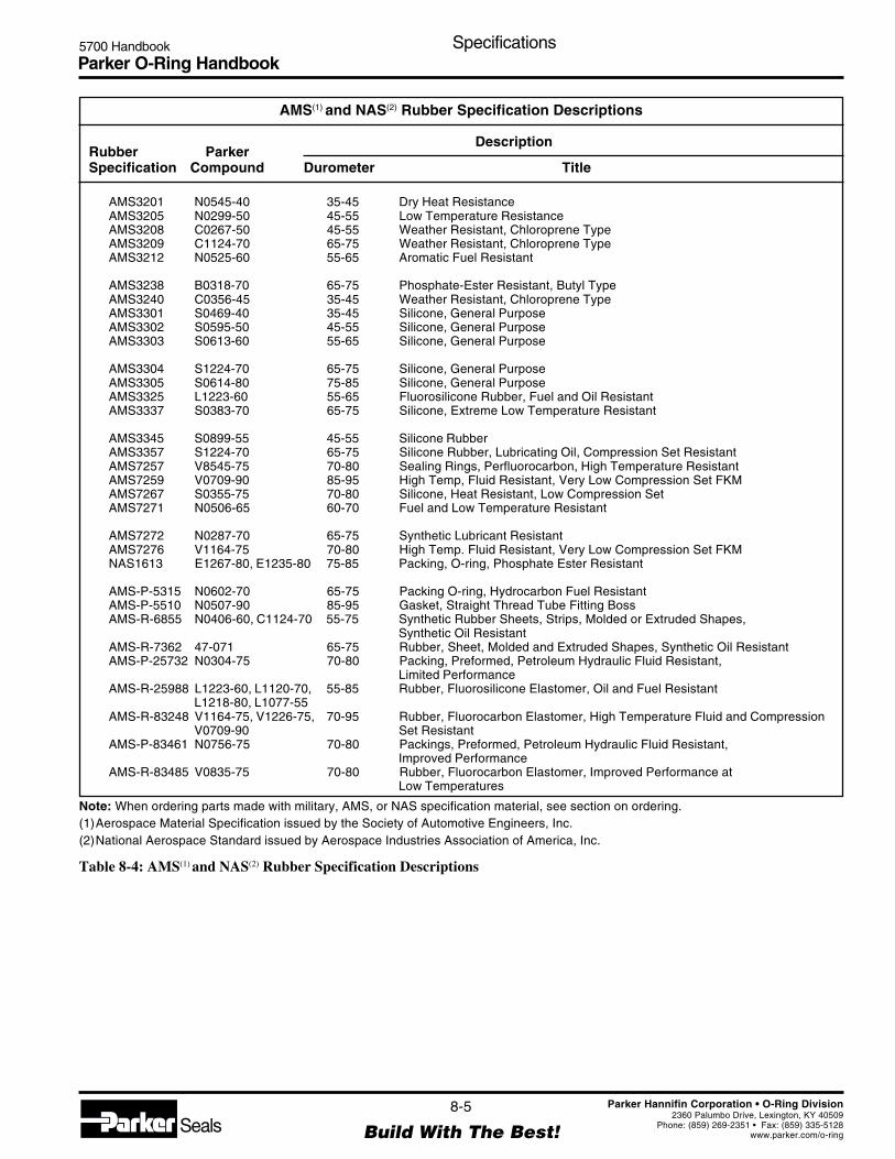
Parker O-Ring Handbook5700 Handbook Specifications
8-5
Build With The Best!SealsParker Hannifin Corporation • O-Ring Division
2360 Palumbo Drive, Lexington, KY 40509Phone: (859) 269-2351 • Fax: (859) 335-5128
www.parker.com/o-ring
AMS(1) and NAS(2) Rubber Specification Descriptions
Rubber ParkerDescription
Specification Compound Durometer Title
AMS3201 N0545-40 35-45 Dry Heat ResistanceAMS3205 N0299-50 45-55 Low Temperature ResistanceAMS3208 C0267-50 45-55 Weather Resistant, Chloroprene TypeAMS3209 C1124-70 65-75 Weather Resistant, Chloroprene TypeAMS3212 N0525-60 55-65 Aromatic Fuel Resistant
AMS3238 B0318-70 65-75 Phosphate-Ester Resistant, Butyl TypeAMS3240 C0356-45 35-45 Weather Resistant, Chloroprene TypeAMS3301 S0469-40 35-45 Silicone, General PurposeAMS3302 S0595-50 45-55 Silicone, General PurposeAMS3303 S0613-60 55-65 Silicone, General Purpose
AMS3304 S1224-70 65-75 Silicone, General PurposeAMS3305 S0614-80 75-85 Silicone, General PurposeAMS3325 L1223-60 55-65 Fluorosilicone Rubber, Fuel and Oil ResistantAMS3337 S0383-70 65-75 Silicone, Extreme Low Temperature Resistant
AMS3345 S0899-55 45-55 Silicone RubberAMS3357 S1224-70 65-75 Silicone Rubber, Lubricating Oil, Compression Set ResistantAMS7257 V8545-75 70-80 Sealing Rings, Perfluorocarbon, High Temperature ResistantAMS7259 V0709-90 85-95 High Temp, Fluid Resistant, Very Low Compression Set FKMAMS7267 S0355-75 70-80 Silicone, Heat Resistant, Low Compression SetAMS7271 N0506-65 60-70 Fuel and Low Temperature Resistant
AMS7272 N0287-70 65-75 Synthetic Lubricant ResistantAMS7276 V1164-75 70-80 High Temp. Fluid Resistant, Very Low Compression Set FKMNAS1613 E1267-80, E1235-80 75-85 Packing, O-ring, Phosphate Ester Resistant
AMS-P-5315 N0602-70 65-75 Packing O-ring, Hydrocarbon Fuel ResistantAMS-P-5510 N0507-90 85-95 Gasket, Straight Thread Tube Fitting BossAMS-R-6855 N0406-60, C1124-70 55-75 Synthetic Rubber Sheets, Strips, Molded or Extruded Shapes,
Synthetic Oil ResistantAMS-R-7362 47-071 65-75 Rubber, Sheet, Molded and Extruded Shapes, Synthetic Oil ResistantAMS-P-25732 N0304-75 70-80 Packing, Preformed, Petroleum Hydraulic Fluid Resistant,
Limited PerformanceAMS-R-25988 L1223-60, L1120-70, 55-85 Rubber, Fluorosilicone Elastomer, Oil and Fuel Resistant
L1218-80, L1077-55AMS-R-83248 V1164-75, V1226-75, 70-95 Rubber, Fluorocarbon Elastomer, High Temperature Fluid and Compression
V0709-90 Set ResistantAMS-P-83461 N0756-75 70-80 Packings, Preformed, Petroleum Hydraulic Fluid Resistant,
Improved PerformanceAMS-R-83485 V0835-75 70-80 Rubber, Fluorocarbon Elastomer, Improved Performance at
Low Temperatures
Note: When ordering parts made with military, AMS, or NAS specification material, see section on ordering.(1)Aerospace Material Specification issued by the Society of Automotive Engineers, Inc.(2)National Aerospace Standard issued by Aerospace Industries Association of America, Inc.
Table 8-4: AMS(1) and NAS(2) Rubber Specification Descriptions

Parker O-Ring Handbook5700 Handbook Specifications
8-6
Build With The Best!SealsParker Hannifin Corporation • O-Ring Division
2360 Palumbo Drive, Lexington, KY 40509Phone: (859) 269-2351 • Fax: (859) 335-5128
www.parker.com/o-ring
Compound Selections For Commonly Used SAE and ASTM Specifications
This table is in accordance with the 1997 revision of ASTMD2000, which requires that minimum tensile strength indi-cations shall be expressed in SI units (Megapascals). The“M” prefix in these callouts signifies this fact, and therequirement is shown in the 6th and 7th characters of eachspecification (excluding the “ASTM D2000”). For ex-
ample, in the specification number M2BC614, the “14”indicates that the tensile strength of the material shall notfall below 14 MPa. To convert this value to PSI (pounds persquare inch), multiply by 145. In this example, the equiva-lent is 104.1 Bar (2030 PSI) .
Compound Selections for Commonly Used SAE and ASTM Specifications
ASTM D735-58/ ParkerASTM D2000-97 SAE J14 Compound
Specification Specification Number
M2AA708 A13 EA14 F17 E0603-70M2AA710 A13 B13 F17 G0244-70M2AA810 A13 EA14 F17 Z1 (Purple) E0893-80M2AA810 A13 EA14 F17 R810BF2 E0515-80M2AA810 A13 EA14 F17 R810BF2 E0540-80M2AA907 A13 EA14 F17 E0652-90
M2BC410 A14 B14 EO14 EO34 F17 Z1 (45 ± 5 Type A Durometer) C0356-45M2BC510 A14 B14 EO14 EO34 F17 SC515BE1E3F2 C0267-50M3BC614 A14 B14 EO14 EO34 F17 SC615BE1E3F1 C0518-70M3BC710 A14 B14 EP14 EO34 SC715BE3F1 C0873-70M3BC714 A14 B14 EO14 EO34 F17 SC715BE3F2 C0147-70
M2BE510 A14 B14 EO14 EO34 F17 C0267-50M2BE614 A14 B14 EO14 EO34 F17 C0518-60M3BE710 A14 B14 EO14 EO34 C0873-70M2BE714 A14 B14 EO14 EO34 F17 C0147-70
M2BF714 B34 EO14 EO34 N0674-70
M2BG410 B34 EA14 EF11 EF21 EO14 EO34 SB415BE1E3F1 N0545-40M5BG410 A14 B34 EO14 EO34 N0545-40M2BG510 B14 EA14 EF11 EF21 EO14 EO34 F17 SB515BE
1E
3F
2N0299-50
M2BG510 B14 N0299-50M2BG608 B34 EA14 EO14 F17 Z1 (65 ± 5 Type A Durometer) SB712BE1F2 N0506-65M2BG614 B34 EA14 EF11 EF21 EO14 EO34 F17 SB620BE
1F
1N0525-60
M2BG708 EA14 EF11 EF21 EO14 EO34 F17 N0602-70M2BG708 EF11 EF21 EO34 F17 47-071M5BG710 A14 B14 N0497-70M2BG710 B14 B34 EA14 EF11 EF21 N0497-70M2BG710 B34 EA14 EF21 EO14 EO34 F17 Z1 (Molydisulfide filled) N0163-70M2BG714 B14 B34 EA14 EF11 EF21 EO14 EO34 SB715BE
1E
3F
1N0674-70
M(5)BG714 A14 B14 B34 EO14 EO34 N0103-70M2BG714 B14 B34 EA14 EF11 EF21 EO34 F17 SB715BE1E3F2 N0103-70M4BG721 B14 EO14 EO34 P0642-70M7BG810 EA14 EF11 EF21 EO14 EO34 Z1 (75 ± 5 Type A Durometer) Z2 (1) N0951-75
M7BG810 EA14 EF11 EO14 EO34 F16 Z1 (75 ± 5 Type A Durometer) SB708E1E3F2 N0304-75M7BG814 EA14 EF11 EO14 EO34 Z1 (85 ± 5 Type A Durometer) Z2 (Graphite filled) SB820BE1E3 N0258-85M6BG910 A14 EO14 EO34 P0648-90M7BG910 B14 EA14 EF11 EF21 EO14 EO34 F16 SB915E1E3 N0507-90M2BG910 B14 EA14 EF21 EO14 EO34 SB915BE1E3 N0552-90M7BG910 EA14 EF11 EF21 EO14 EO34 P0648-90
M(2)CA614 A25 B44 E0529-60M4CA714 A25 B35 EA14 F17 G21 E0803-70M8CA814 A25 B35 EA14 F17 E0810-80
Prefix (grade) numbers and suffix letters in parenthesis are technically “not permitted”, but nevertheless, they describe a property of the material.Explanations in parenthesis apply to the Z suffix letters.(1) Compression Set = 20% max. after 70 hours at 125°C when tested on plied discs per ASTM D395.
Table 8-5: Compound Selectons for Commonly Used SAE and ASTM Specifications

Parker O-Ring Handbook5700 Handbook Specifications
8-7
Build With The Best!SealsParker Hannifin Corporation • O-Ring Division
2360 Palumbo Drive, Lexington, KY 40509Phone: (859) 269-2351 • Fax: (859) 335-5128
www.parker.com/o-ring
Compound Selections for Commonly Used SAE and ASTM Specifications (Continued)
ASTM D735-58/ ParkerASTM D2000-97 SAE J14 Compound
Specification Specification Number
M2CH608 A25 B34 F17 Z1 (65 ± 5 Type A Durometer) N0506-65M3CH708 A25 EO16 EO36 N0497-70M2CH708 A25 EO35 F17 47-071M3CH710 A25 B34 EO16 EO36 Z1 (Molydisulfide filled) N0163-70M3CH714 A25 B34 EO16 EO36 N0674-70M3CH810 A25 EO16 Z1 (70 ± 5 Type A Durometer) Z2 (1) N0951-75M3CH810 A25 EO16 Z1 (75 ± 5 Type A Durometer) N0304-75M3CH910 B34 EO16 EO36 N0552-90
M3DA810 A26 B36 EA14 E0540-80
M3DH710 A26 B16 EO16 EO36 F13 TB715E1E
3A1107-70
M2FK606 A19 EA36 L1223-60
M2GE405 A19 B37 EA14 EO16 EO36 F19 G11 S0469-40M3GE503 A19 B37 EA14 EO16 EO36 F19 G11 TA507BE1E3F2 S0595-50M3GE603 A19 B37 EA14 EO16 EO36 F19 G11 TA605BE1E3F2 S0613-60M7GE705 A19 B37 EA14 EO16 EO36 F19 G11 TA705BE
1E
3F
2S0455-70
A7GE705 A19 B37 EA14 EO16 EO36 F19 G11 TA705BE1E3F2 S1224-70M6GE803 A19 B37 EA14 EO16 EO36 F19 G11 TA805BE1E3F2 S0614-80
M2HK710 A1 - 10 B37 B38 EF31 EO78 F15 Z1 (75 ± 5 Type A Durometer) V1164-75M2HK710 A1 - 10 B37 B38 EF31 EO78 F15 Z1 (75 ± 5 Type A Durometer) Z2 (Brown) V1226-75M4HK710 A1 - 11 B38 EF31 EO78 Z1 (75 ± 5 Type A Durometer) V1164-75M4HK710 A1 - 11 B38 EF31 EO78 Z1 (75 ± 5 Type A Durometer) Z2 (Brown) V1226-75M3HK910 A1 - 10 B37 EF31 EO78 V0709-90M3HK910 A1 - 10 B37 B38 EF31 EO78 Z1 (Brown) V0894-90M5HK910 A1 - 11 B38 EF31 EO78 F15 V0709-90M5HK910 A1 - 11 B38 EF31 EO78 F15 Z1 (Brown) V0894-90
SAE 120R1 Class 2 N0497-70SAE J515 Type 1 N0552-90SAE J515 Type 2 E0652-90
Prefix (grade) numbers and suffix letters in parenthesis are technically “not permitted,” but nevertheless, they describe a property of the material.Explanations in parenthesis apply to the Z suffix letters.(1) Compression Set = 20% max. after 70 hours at 125°C when tested on plied discs per ASTM D395.
Table 8-5: Compound Selectons for Commonly Used SAE and ASTM Specifications (Continued)

Parker O-Ring Handbook5700 Handbook Specifications
8-8
Build With The Best!SealsParker Hannifin Corporation • O-Ring Division
2360 Palumbo Drive, Lexington, KY 40509Phone: (859) 269-2351 • Fax: (859) 335-5128
www.parker.com/o-ring
8.2 International O-Ring Standards and TestMethods
GermanyDIN 3770
Sealing rings (O-rings) with special accuracy made ofelastomeric materials. This standard should not be usedfor new designs.
DIN 3771 Part 1Fluid systems, O-rings, sizes to ISO 3601-1.This standard contains sizes and tolerances of O-ringswith special accuracy for general applications in fluidsystems.
DIN 3771 Part 2Fluid systems, O-rings, testing, marking.This standard applies to DIN 3771 Part 1, testing andmarking of O-rings.
DIN 3771 Part 3Fluid systems, O-rings, field of application, materials.This standard covers materials, their hardness range andfields of application of O-rings to DIN 3771 Part 1.
DIN 3771 Part 4Fluid systems, O-rings, quality acceptance criteria, sur-face finish and form.This standard covers acceptance criteria for surfacefinish and form.
DIN 7715Rubber parts; tolerances, molded shapes from soft rub-ber (elastomers).
DIN 7716Products from rubber; requirements for storage, clean-ing and servicing.
DIN 9088Aerospace; shelf-life of parts from elastomers (underpreparation).
DIN 24 320Fire resistant hydraulic fluids, group HFA-1, propertiesand requirements.
DIN 40 080Procedures and tables for inspection by attributes —statistical sampling.
DIN 50 049Certification of material testing.
DIN 51 524Hydraulic fluids, hydraulic oils H and H-L; minimumrequirements.
DIN 51 525Hydraulic fluids; hydraulic oils H-LP; minimum re-quirements.
DIN 51 600Liquid fuels, leaded petroleum oils; minimum require-ments.
DIN 51 601Liquid fuels, Diesel oil; minimum requirements.
DIN 51 603 Part 1Liquid fuels; heating oils, heating oil EL; minimumrequirements.
DIN 51 603 Part 2Liquid fuels; heating oils, heating oils L. M and S;minimum requirements.
DIN 53 479Testing of plastics and elastomers; measurement ofspecific gravity.
DIN 53 504Testing of elastomers; measurement of tensile strength,maximum stress, elongation at break and stress values attensile test.
DIN 53 505Testing of elastomers; Shore A and D hardness tests.
DIN 53 507Testing of elastomers; determination of tear growth,strip specimen.
DIN 53 512Testing of rubbers; determination of rebound resilience.
DIN 53 516Testing of rubbers and elastomers; determination ofabrasion resistance.
DIN 53 517Testing of elastomers - determination of compressionset.
DIN 53 519 Part 1Testing of elastomers; determination of indentationhardness of soft rubber (IRHD),hardness test on samples.
DIN 53 519 Part 2Testing of elastomers; determination of indentationhardness of soft rubber (IRHD), microhardness onsamples of minor dimensions.
DIN 53 521Testing of rubber and elastomers; determination of theresistance to liquids, vapors and gases.
DIN 53 522Testing of elastomers; determination of resistance toflex-cracking and crack growth.
DIN 53 538Standard reference elastomer; nitrile-butadiene rubber(NBR), cross-linked by peroxide to characterize work-ing fluids with respect to their reaction on NBR.

Parker O-Ring Handbook5700 Handbook Specifications
8-9
Build With The Best!SealsParker Hannifin Corporation • O-Ring Division
2360 Palumbo Drive, Lexington, KY 40509Phone: (859) 269-2351 • Fax: (859) 335-5128
www.parker.com/o-ring
DIN 53 545Testing of rubber; determination of the behavior at lowtemperature (behaviour to cold), principles, testing meth-ods.
DIN 53 670Testing of rubber or elastomers; testing of rubber instandard text mixtures, equipment and procedures.
DIN ISO 1629Rubber and latex; difference and abbreviations.
VDMA 24 317Fluid systems; hydraulic, fire-resistant hydraulic fluids,guidelines.
LN 9214Aerospace; toroidal sealing rings (O-rings) for solderlesstube fittings with coupling sleeves, flareless.
InternationalISO 3601/1
Fluid systems, O-rings - Part 1. Inner diameters, cross-sections, tolerances and size coding.
ISO 3601/2 (under preparation)Fluid systems, O-rings - Part 2. Design criteria forO-ring grooves.
ISO 3601/3 (under preparation)Fluid systems. O-rings - Part 3. Quality acceptancelevels.
ISO 3601/4 (under preparation)Fluid systems, O-rings - Part 4. O-ring grooves withback-up rings.
ISO 3601/5 (under preparation)Fluid systems, O-rings - Part 5. O-rings for connectorsto ISO 6149.
United KingdomBS 1806
Specifies dimensions (inches) for inner diameters andcross-sections and their tolerances including grooves.O-ring dimensions are identical with the Parker 2-xxxseries. Table 11.1 gives a cross-reference among thevarious European standard specifications.
BS 4518Specifies dimensions and tolerances together with groovedimensions. Cross-section diameters are: 1.6 / 2.4 / 3.0 / 5.7and 8.4 mm
FranceThe following French standards base upon ISO 3601Parts 1 to 3:NF-T-47-501 is comparable with ISO 3601 Part 1.NF-T-47-502 is comparable with ISO 3601 Part 2.NF-T-47-503 is comparable with ISO 3601 Part 3.French purchase codes R 1 to R 27 are identical withParker sizes 5-578 to 5-606. R 28 to R 88 are identicalwith Parker sizes 2-325 to 2-349 and 2-425 to 2-460. Formore details, cf European O-ring codes, Table 11.1.
ItalyA committee for seal and hose standardization exists inthe UNI which recommends the use of the American AS568 A standard specification.In certain areas the French R 1 to R 88 are used.
SwedenO-rings are standardized under SMS 1586, Swedishmilitary standard. Cross sections 1.6 / 2.4 / 3.0 / 5.7 and8.4 mm are recommended.
United StatesAS 568 A (Aerospace Standard)
Published by the SAE (Society of Automotive Engi-neers) specifies sizes and tolerances.The cross-section tolerances correspond to ISO 3601/1and DIN 3771 Part 1 (within a few hundredths of amillimeter), see Table 11.1, Cross Reference List.
8.3 Ordering Addresses
DIN and DIN ISO standard specifications and VDMArecommendations can be obtained from:
Beuth Verlag GmbHBurggrafenstrasse 4-10, D-10787Berlin
AMS and SAE specifications can be obtained from:
SAE400 Commonwealth Dr.Warrendale, PA 15096-0001
ASTM standard specifications can be obtained from:
ASTM100 Barr Harbor Drive.West Conshohocken, PA 19428
Military specifications can be obtained from:
Defense Automated Printing Service700 Robbins Ave., Building 4/DPhiladelphia, PA 19111-5094ATTN: DODSSP

Parker O-Ring Handbook5700 Handbook Sizes
9-1
Build With The Best!SealsParker Hannifin Corporation • O-Ring Division
2360 Palumbo Drive, Lexington, KY 40509Phone: (859) 269-2351 • Fax: (859) 335-5128
www.parker.com/o-ring
Section IXSizes
Parker Series 2-XXX O-Ring Sizes .............................................................................................................. 9-2
Parker Series 3-XXX O-Ring Sizes ........................................................................................................... .9-11
Parker Series 5-XXX O-Ring Sizes ........................................................................................................... .9-12
Series 5- XXX Locator Table...................................................................................................................... 9-17
ISO 3601-1, Series A Sizes ......................................................................................................................... 9-19
ISO 3601-1, Series G Sizes ......................................................................................................................... 9-20
JIS B2401 Sizes .......................................................................................................................................... 9-21

Parker O-Ring Handbook5700 Handbook Sizes
9-2
Build With The Best!SealsParker Hannifin Corporation • O-Ring Division
2360 Palumbo Drive, Lexington, KY 40509Phone: (859) 269-2351 • Fax: (859) 335-5128
www.parker.com/o-ring
2-001 -001 1/32 3/32 1/32 .029 .004 .040 .003 .0003 0,74 0,10 1,02 0,08 2-0012-002 -002 3/64 9/64 3/64 .042 .004 .050 .003 .0006 1,07 0,10 1,27 0,08 2-0022-003 -003 1/16 3/16 1/16 .056 .004 .060 .003 .0010 1,42 0,10 1,52 0,08 2-0032-004 -004 5/64 13/64 1/16 .070 .005 .070 .003 .0017 1,78 0,13 1,78 0,08 2-0042-005 -005 3/32 7/32 1/16 .101 .005 .070 .003 .0021 2,57 0,13 1,78 0,08 2-005
2-006 -006 1/8 1/4 1/16 .114 .005 .070 .003 .0022 2,90 0,13 1,78 0,08 2-0062-007 -007 5/32 9/32 1/16 .145 .005 .070 .003 .0026 3,68 0,13 1,78 0,08 2-0072-008 -008 3/16 5/16 1/16 .176 .005 .070 .003 .0030 4,47 0,13 1,78 0,08 2-0082-009 -009 7/32 11/32 1/16 .208 .005 .070 .003 .0034 5,28 0,13 1,78 0,08 2-0092-010 -010 1/4 3/8 1/16 .239 .005 .070 .003 .0037 6,07 0,13 1,78 0,08 2-010
2-011 -011 5/16 7/16 1/16 .301 .005 .070 .003 .0045 7,65 0,13 1,78 0,08 2-0112-012 -012 3/8 1/2 1/16 .364 .005 .070 .003 .0052 9,25 0,13 1,78 0,08 2-0122-013 -013 7/16 9/16 1/16 .426 .005 .070 .003 .0060 10,82 0,13 1,78 0,08 2-0132-014 -014 1/2 5/8 1/16 .489 .005 .070 .003 .0068 12,42 0,13 1,78 0,08 2-0142-015 -015 9/16 11/16 1/16 .551 .007 .070 .003 .0075 14,00 0,18 1,78 0,08 2-015
2-016 -016 5/8 3/4 1/16 .614 .009 .070 .003 .0083 15,60 0,23 1,78 0,08 2-0162-017 -017 11/16 13/16 1/16 .676 .009 .070 .003 .0090 17,17 0,23 1,78 0,08 2-0172-018 -018 3/4 7/8 1/16 .739 .009 .070 .003 .0098 18,77 0,23 1,78 0,08 2-0182-019 -019 13/16 15/16 1/16 .801 .009 .070 .003 .0105 20,35 0,23 1,78 0,08 2-0192-020 -020 7/8 1 1/16 .864 .009 .070 .003 .0113 21,95 0,23 1,78 0,08 2-020
2-021 -021 15/16 1 1/16 1/16 .926 .009 .070 .003 .0120 23,52 0,23 1,78 0,08 2-0212-022 -022 1 1/8 1/16 .989 .010 .070 .003 .0128 25,12 0,25 1,78 0,08 2-0222-023 -023 1 1/16 1 3/16 1/16 1.051 .010 .070 .003 .0136 26,70 0,25 1,78 0,08 2-0232-024 -024 1 1/8 1 1/4 1/16 1.114 .010 .070 .003 .0143 28,30 0,25 1,78 0,08 2-0242-025 -025 1 3/16 1 5/16 1/16 1.176 .011 .070 .003 .0151 29,87 0,28 1,78 0,08 2-025
2-026 -026 1 1/4 1 3/8 1/16 1.239 .011 .070 .003 .0158 31,47 0,28 1,78 0,08 2-0262-027 -027 1 5/16 1 7/16 1/16 1.301 .011 .070 .003 .0166 33,05 0,28 1,78 0,08 2-0272-028 -028 1 3/8 1 1/2 1/16 1.364 .013 .070 .003 .0173 34,65 0,33 1,78 0,08 2-0282-029 -029 1 1/2 1 5/8 1/16 1.489 .013 .070 .003 .0188 37,82 0,33 1,78 0,08 2-0292-030 -030 1 5/8 1 3/4 1/16 1.614 .013 .070 .003 .0204 41,00 0,33 1,78 0,08 2-030
2-031 -031 1 3/4 1 7/8 1/16 1.739 .015 .070 .003 .0219 44,17 0,38 1,78 0,08 2-0312-032 -032 1 7/8 2 1/16 1.864 .015 .070 .003 .0234 47,35 0,38 1,78 0,08 2-0322-033 -033 2 2 1/8 1/16 1.989 .018 .070 .003 .0249 50,52 0,46 1,78 0,08 2-0332-034 -034 2 1/8 2 1/4 1/16 2.114 .018 .070 .003 .0264 53,70 0,46 1,78 0,08 2-0342-035 -035 2 1/4 2 3/8 1/16 2.239 .018 .070 .003 .0279 56,87 0,46 1,78 0,08 2-035
2-036 -036 2 3/8 2 1/2 1/16 2.364 .018 .070 .003 .0294 60,05 0,46 1,78 0,08 2-0362-037 -037 2 1/2 2 5/8 1/16 2.489 .018 .070 .003 .0309 63,22 0,46 1,78 0,08 2-0372-038 -038 2 5/8 2 3/4 1/16 2.614 .020 .070 .003 .0324 66,40 0,51 1,78 0,08 2-0382-039 -039 2 3/4 2 7/8 1/16 2.739 .020 .070 .003 .0340 69,57 0,51 1,78 0,08 2-0392-040 -040 2 7/8 3 1/16 2.864 .020 .070 .003 .0355 72,75 0,51 1,78 0,08 2-040
.040 Area = .001256
.050 Area = .001964
.060 Area = .002827
.070 Area = .003848
(sq. in.)
1 2 3 4 5 6 7Size Nominal Standard O-Ring Size (Ref. Metric O-Ring SizeOnly Size (Units are in Inches) Only) (Units are in Millimeters)
(Size Only) (Inches) Actual (b) Per AS 568A Actual (b) Per AS 568A
Parker ParkerSize No. AS 568A (Ref. Only) Tolerance Basic Tolerance Size No.
(Size Only) Uniform Volume (Size Only)
(a) Dash No. I.D. O.D. W. I.D. ± W ± Cu. In. I.D. ± W ± (a)
Parker Series 2-XXX O-Ring Sizes
(a) The rubber compound must be added when ordering by the 2-size number (i.e., 2-007 N0674-70).
(b) This chart provides dimensions for standard (AN) shrinkage materials ONLY. These correspond to AS568Adimensions. O-rings manufactured out of compounds with different shrinkage rates (other than AN) will produceslightly different dimensions and tolerances. For more information on shrinkage rates, see the Appendix.
(c) When ordering O-rings to a Military, AMS or NAS material Specification, see Section VIII, Specifications, for moreinformation.
Table 9-1: Parker Series 2-XXX O-Ring Sizes
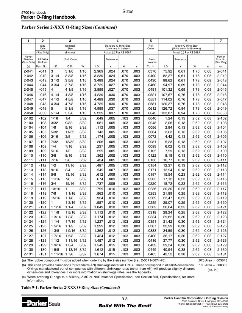
Parker O-Ring Handbook5700 Handbook Sizes
9-3
Build With The Best!SealsParker Hannifin Corporation • O-Ring Division
2360 Palumbo Drive, Lexington, KY 40509Phone: (859) 269-2351 • Fax: (859) 335-5128
www.parker.com/o-ring
2-041 -041 3 3 1/8 1/16 2.989 .024 .070 .003 .0370 75,92 0,61 1,78 0,08 2-0412-042 -042 3 1/4 3 3/8 1/16 3.239 .024 .070 .003 .0400 82,27 0,61 1,78 0,08 2-0422-043 -043 3 1/2 3 5/8 1/16 3.489 .024 .070 .003 .0430 88,62 0,61 1,78 0,08 2-0432-044 -044 3 3/4 3 7/8 1/16 3.739 .027 .070 .003 .0460 94,97 0,69 1,78 0,08 2-0442-045 -045 4 4 1/8 1/16 3.989 .027 .070 .003 .0491 101,32 0,69 1,78 0,08 2-045
2-046 -046 4 1/4 4 3/8 1/16 4.239 .030 .070 .003 .0521 107,67 0,76 1,78 0,08 2-0462-047 -047 4 1/2 4 5/8 1/16 4.489 .030 .070 .003 .0551 114,02 0,76 1,78 0,08 2-0472-048 -048 4 3/4 4 7/8 1/16 4.739 .030 .070 .003 .0581 120,37 0,76 1,78 0,08 2-0482-049 -049 5 5 1/8 1/16 4.989 .037 .070 .003 .0612 126,72 0,94 1,78 0,08 2-0492-050 -050 5 1/4 5 3/8 1/16 5.239 .037 .070 .003 .0642 133,07 0,94 1,78 0,08 2-050
2-102 -102 1/16 1/4 3/32 .049 .005 .103 .003 .0040 1,24 0,13 2,62 0,08 2-1022-103 -103 3/32 9/32 3/32 .081 .005 .103 .003 .0048 2,06 0,13 2,62 0,08 2-1032-104 -104 1/8 5/16 3/32 .112 .005 .103 .003 .0056 2,84 0,13 2,62 0,08 2-1042-105 -105 5/32 11/32 3/32 .143 .005 .103 .003 .0064 3,63 0,13 2,62 0,08 2-1052-106 -106 3/16 3/8 3/32 .174 .005 .103 .003 .0072 4,42 0,13 2,62 0,08 2-106
2-107 -107 7/32 13/32 3/32 .206 .005 .103 .003 .0081 5,23 0,13 2,62 0,08 2-1072-108 -108 1/4 7/16 3/32 .237 .005 .103 .003 .0089 6,02 0,13 2,62 0,08 2-1082-109 -109 5/16 1/2 3/32 .299 .005 .103 .003 .0105 7,59 0,13 2,62 0,08 2-1092-110 -110 3/8 9/16 3/32 .362 .005 .103 .003 .0122 9,19 0,13 2,62 0,08 2-1102-111 -111 7/16 5/8 3/32 .424 .005 .103 .003 .0138 10,77 0,13 2,62 0,08 2-111
2-112 -112 1/2 11/16 3/32 .487 .005 .103 .003 .0154 12,37 0,13 2,62 0,08 2-1122-113 -113 9/16 3/4 3/32 .549 .007 .103 .003 .0171 13,94 0,18 2,62 0,08 2-1132-114 -114 5/8 13/16 3/32 .612 .009 .103 .003 .0187 15,54 0,23 2,62 0,08 2-1142-115 -115 11/16 7/8 3/32 .674 .009 .103 .003 .0203 17,12 0,23 2,62 0,08 2-1152-116 -116 3/4 15/16 3/32 .737 .009 .103 .003 .0220 18,72 0,23 2,62 0,08 2-116
2-117 -117 13/16 1 3/32 .799 .010 .103 .003 .0236 20,30 0,25 2,62 0,08 2-1172-118 -118 7/8 1 1/16 3/32 .862 .010 .103 .003 .0253 21,89 0,25 2,62 0,08 2-1182-119 -119 15/16 1 1/8 3/32 .924 .010 .103 .003 .0269 23,47 0,25 2,62 0,08 2-1192-120 -120 1 1 3/16 3/32 .987 .010 .103 .003 .0285 25,07 0,25 2,62 0,08 2-1202-121 -121 1 1/16 1 1/4 3/32 1.049 .010 .103 .003 .0302 26,64 0,25 2,62 0,08 2-121
2-122 -122 1 1/8 1 5/16 3/32 1.112 .010 .103 .003 .0318 28,24 0,25 2,62 0,08 2-1222-123 -123 1 3/16 1 3/8 3/32 1.174 .012 .103 .003 .0334 29,82 0,30 2,62 0,08 2-1232-124 -124 1 1/4 1 7/16 3/32 1.237 .012 .103 .003 .0351 31,42 0,30 2,62 0,08 2-1242-125 -125 1 5/16 1 1/2 3/32 1.299 .012 .103 .003 .0367 32,99 0,30 2,62 0,08 2-1252-126 -126 1 3/8 1 9/16 3/32 1.362 .012 .103 .003 .0383 34,59 0,30 2,62 0,08 2-126
2-127 -127 1 7/16 1 5/8 3/32 1.424 .012 .103 .003 .0400 36,17 0,30 2,62 0,08 2-1272-128 -128 1 1/2 1 11/16 3/32 1.487 .012 .103 .003 .0416 37,77 0,30 2,62 0,08 2-1282-129 -129 1 9/16 1 3/4 3/32 1.549 .015 .103 .003 .0432 39,34 0,38 2,62 0,08 2-1292-130 -130 1 5/8 1 13/16 3/32 1.612 .015 .103 .003 .0449 40,94 0,38 2,62 0,08 2-1302-131 -131 1 11/16 1 7/8 3/32 1.674 .015 .103 .003 .0465 42,52 0,38 2,62 0,08 2-131
Parker Series 2-XXX O-Ring Sizes (Continued)
.070 Area = .003848
.103 Area = .008332
(sq. in.)
(a) The rubber compound must be added when ordering by the 2-size number (i.e., 2-007 N0674-70).
(b) This chart provides dimensions for standard (AN) shrinkage materials ONLY. These correspond to AS568A dimensions.O-rings manufactured out of compounds with different shrinkage rates (other than AN) will produce slightly differentdimensions and tolerances. For more information on shrinkage rates, see the Appendix.
(c) When ordering O-rings to a Military, AMS or NAS material Specification, see Section VIII, Specifications, for moreinformation.
Table 9-1: Parker Series 2-XXX O-Ring Sizes (Continued)
1 2 3 4 5 6 7Size Nominal Standard O-Ring Size (Ref. Metric O-Ring SizeOnly Size (Units are in Inches) Only) (Units are in Millimeters)
(Size Only) (Inches) Actual (b) Per AS 568A Actual (b) Per AS 568A
Parker ParkerSize No. AS 568A (Ref. Only) Tolerance Basic Tolerance Size No.
(Size Only) Uniform Volume (Size Only)
(a) Dash No. I.D. O.D. W. I.D. ± W ± Cu. In. I.D. ± W ± (a)

Parker O-Ring Handbook5700 Handbook Sizes
9-4
Build With The Best!SealsParker Hannifin Corporation • O-Ring Division
2360 Palumbo Drive, Lexington, KY 40509Phone: (859) 269-2351 • Fax: (859) 335-5128
www.parker.com/o-ring
2-132 -132 1 3/4 1 15/16 3/32 1.737 .015 .103 .003 .0482 44,12 0,38 2,62 0,08 2-1322-133 -133 1 13/16 2 3/32 1.799 .015 .103 .003 .0498 45,69 0,38 2,62 0,08 2-1332-134 -134 1 7/8 2 1/16 3/32 1.862 .015 .103 .003 .0514 47,29 0,38 2,62 0,08 2-1342-135 -135 1 15/16 2 1/8 3/32 1.925 .017 .103 .003 .0531 48,90 0,43 2,62 0,08 2-1352-136 -136 2 2 3/16 3/32 1.987 .017 .103 .003 .0547 50,47 0,43 2,62 0,08 2-136
2-137 -137 2 1/16 2 1/4 3/32 2.050 .017 .103 .003 .0564 52,07 0,43 2,62 0,08 2-1372-138 -138 2 1/8 2 5/16 3/32 2.112 .017 .103 .003 .0580 53,64 0,43 2,62 0,08 2-1382-139 -139 2 3/16 2 3/8 3/32 2.175 .017 .103 .003 .0596 55,25 0,43 2,62 0,08 2-1392-140 -140 2 1/4 2 7/16 3/32 2.237 .017 .103 .003 .0612 56,82 0,43 2,62 0,08 2-1402-141 -141 2 5/16 2 1/2 3/32 2.300 .020 .103 .003 .0629 58,42 0,51 2,62 0,08 2-141
2-142 -142 2 3/8 2 9/16 3/32 2.362 .020 .103 .003 .0645 59,99 0,51 2,62 0,08 2-1422-143 -143 2 7/16 2 5/8 3/32 2.425 .020 .103 .003 .0662 61,60 0,51 2,62 0,08 2-1432-144 -144 2 1/2 2 11/16 3/32 2.487 .020 .103 .003 .0678 63,17 0,51 2,62 0,08 2-1442-145 -145 2 9/16 2 3/4 3/32 2.550 .020 .103 .003 .0694 64,77 0,51 2,62 0,08 2-1452-146 -146 2 5/8 2 13/16 3/32 2.612 .020 .103 .003 .0711 66,34 0,51 2,62 0,08 2-146
2-147 -147 2 11/16 2 7/8 3/32 2.675 .022 .103 .003 .0727 67,95 0,56 2,62 0,08 2-1472-148 -148 2 3/4 2 15/16 3/32 2.737 .022 .103 .003 .0743 69,52 0,56 2,62 0,08 2-1482-149 -149 2 13/16 3 3/32 2.800 .022 .103 .003 .0760 71,12 0,56 2,62 0,08 2-1492-150 -150 2 7/8 3 1/16 3/32 2.862 .022 .103 .003 .0776 72,69 0,56 2,62 0,08 2-1502-151 -151 3 3 3/16 3/32 2.987 .024 .103 .003 .0809 75,87 0,61 2,62 0,08 2-151
2-152 -152 3 1/4 3 7/16 3/32 3.237 .024 .103 .003 .0874 82,22 0,61 2,62 0,08 2-1522-153 -153 3 1/2 3 11/16 3/32 3.487 .024 .103 .003 .0940 88,57 0,61 2,62 0,08 2-1532-154 -154 3 3/4 3 15/16 3/32 3.737 .028 .103 .003 .1005 94,92 0,71 2,62 0,08 2-1542-155 -155 4 4 3/16 3/32 3.987 .028 .103 .003 .1071 101,27 0,71 2,62 0,08 2-1552-156 -156 4 1/4 4 7/16 3/32 4.237 .030 .103 .003 .1136 107,62 0,76 2,62 0,08 2-156
2-157 -157 4 1/2 4 11/16 3/32 4.487 .030 .103 .003 .1202 113,97 0,76 2,62 0,08 2-1572-158 -158 4 3/4 4 15/16 3/32 4.737 .030 .103 .003 .1267 120,32 0,76 2,62 0,08 2-1582-159 -159 5 5 3/16 3/32 4.987 .035 .103 .003 .1332 126,67 0,89 2,62 0,08 2-1592-160 -160 5 1/4 5 7/16 3/32 5.237 .035 .103 .003 .1398 133,02 0,89 2,62 0,08 2-1602-161 -161 5 1/2 5 11/16 3/32 5.487 .035 .103 .003 .1463 139,37 0,89 2,62 0,08 2-161
2-162 -162 5 3/4 5 15/16 3/32 5.737 .035 .103 .003 .1529 145,72 0,89 2,62 0,08 2-1622-163 -163 6 6 3/16 3/32 5.987 .035 .103 .003 .1594 152,07 0,89 2,62 0,08 2-1632-164 -164 6 1/4 6 7/16 3/32 6.237 .040 .103 .003 .1660 158,42 1,02 2,62 0,08 2-1642-165 -165 6 1/2 6 11/16 3/32 6.487 .040 .103 .003 .1725 164,77 1,02 2,62 0,08 2-1652-166 -166 6 3/4 6 15/16 3/32 6.737 .040 .103 .003 .1790 171,12 1,02 2,62 0,08 2-166
2-167 -167 7 7 3/16 3/32 6.987 .040 .103 .003 .1856 177,47 1,02 2,62 0,08 2-1672-168 -168 7 1/4 7 7/16 3/32 7.237 .045 .103 .003 .1921 183,82 1,14 2,62 0,08 2-1682-169 -169 7 1/2 7 11/16 3/32 7.487 .045 .103 .003 .1987 190,17 1,14 2,62 0,08 2-1692-170 -170 7 3/4 7 15/16 3/32 7.737 .045 .103 .003 .2052 196,52 1,14 2,62 0,08 2-1702-171 -171 8 8 3/16 3/32 7.987 .045 .103 .003 .2118 202,87 1,14 2,62 0,08 2-171
.103 Area = .008332
(sq. in.)
1 2 3 4 5 6 7Size Nominal Standard O-Ring Size (Ref. Metric O-Ring SizeOnly Size (Units are in Inches) Only) (Units are in Millimeters)
(Size Only) (Inches) Actual (b) Per AS 568A Actual (b) Per AS 568A
Parker ParkerSize No. AS 568A (Ref. Only) Tolerance Basic Tolerance Size No.
(Size Only) Uniform Volume (Size Only)
(a) Dash No. I.D. O.D. W. I.D. ± W ± Cu. In. I.D. ± W ± (a)
Parker Series 2-XXX O-Ring Sizes (Continued)
(a) The rubber compound must be added when ordering by the 2-size number (i.e., 2-007 N0674-70).
(b) This chart provides dimensions for standard (AN) shrinkage materials ONLY. These correspond to AS568A dimensions.O-rings manufactured out of compounds with different shrinkage rates (other than AN) will produce slightly differentdimensions and tolerances. For more information on shrinkage rates, see the Appendix.
(c) When ordering O-rings to a Military, AMS or NAS material Specification, see Section VIII, Specifications, for moreinformation.
Table 9-1: Parker Series 2-XXX O-Ring Sizes (Continued)
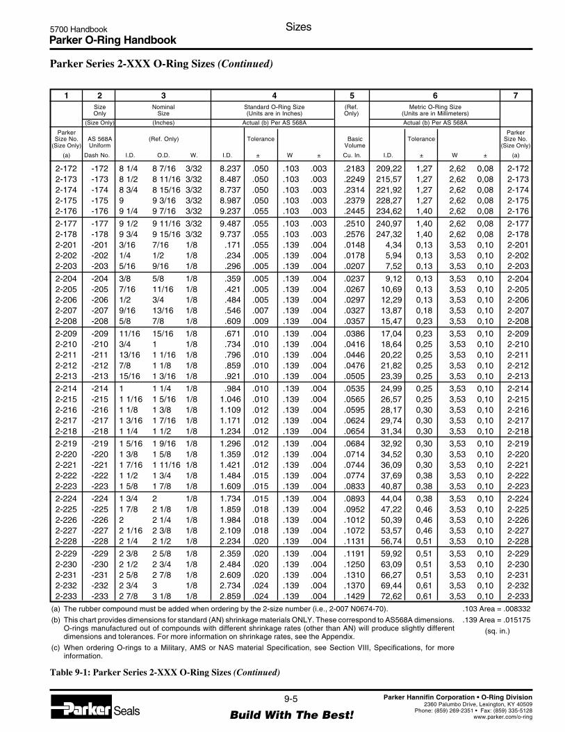
Parker O-Ring Handbook5700 Handbook Sizes
9-5
Build With The Best!SealsParker Hannifin Corporation • O-Ring Division
2360 Palumbo Drive, Lexington, KY 40509Phone: (859) 269-2351 • Fax: (859) 335-5128
www.parker.com/o-ring
2-172 -172 8 1/4 8 7/16 3/32 8.237 .050 .103 .003 .2183 209,22 1,27 2,62 0,08 2-1722-173 -173 8 1/2 8 11/16 3/32 8.487 .050 .103 .003 .2249 215,57 1,27 2,62 0,08 2-1732-174 -174 8 3/4 8 15/16 3/32 8.737 .050 .103 .003 .2314 221,92 1,27 2,62 0,08 2-1742-175 -175 9 9 3/16 3/32 8.987 .050 .103 .003 .2379 228,27 1,27 2,62 0,08 2-1752-176 -176 9 1/4 9 7/16 3/32 9.237 .055 .103 .003 .2445 234,62 1,40 2,62 0,08 2-176
2-177 -177 9 1/2 9 11/16 3/32 9.487 .055 .103 .003 .2510 240,97 1,40 2,62 0,08 2-1772-178 -178 9 3/4 9 15/16 3/32 9.737 .055 .103 .003 .2576 247,32 1,40 2,62 0,08 2-1782-201 -201 3/16 7/16 1/8 .171 .055 .139 .004 .0148 4,34 0,13 3,53 0,10 2-2012-202 -202 1/4 1/2 1/8 .234 .005 .139 .004 .0178 5,94 0,13 3,53 0,10 2-2022-203 -203 5/16 9/16 1/8 .296 .005 .139 .004 .0207 7,52 0,13 3,53 0,10 2-203
2-204 -204 3/8 5/8 1/8 .359 .005 .139 .004 .0237 9,12 0,13 3,53 0,10 2-2042-205 -205 7/16 11/16 1/8 .421 .005 .139 .004 .0267 10,69 0,13 3,53 0,10 2-2052-206 -206 1/2 3/4 1/8 .484 .005 .139 .004 .0297 12,29 0,13 3,53 0,10 2-2062-207 -207 9/16 13/16 1/8 .546 .007 .139 .004 .0327 13,87 0,18 3,53 0,10 2-2072-208 -208 5/8 7/8 1/8 .609 .009 .139 .004 .0357 15,47 0,23 3,53 0,10 2-208
2-209 -209 11/16 15/16 1/8 .671 .010 .139 .004 .0386 17,04 0,23 3,53 0,10 2-2092-210 -210 3/4 1 1/8 .734 .010 .139 .004 .0416 18,64 0,25 3,53 0,10 2-2102-211 -211 13/16 1 1/16 1/8 .796 .010 .139 .004 .0446 20,22 0,25 3,53 0,10 2-2112-212 -212 7/8 1 1/8 1/8 .859 .010 .139 .004 .0476 21,82 0,25 3,53 0,10 2-2122-213 -213 15/16 1 3/16 1/8 .921 .010 .139 .004 .0505 23,39 0,25 3,53 0,10 2-213
2-214 -214 1 1 1/4 1/8 .984 .010 .139 .004 .0535 24,99 0,25 3,53 0,10 2-2142-215 -215 1 1/16 1 5/16 1/8 1.046 .010 .139 .004 .0565 26,57 0,25 3,53 0,10 2-2152-216 -216 1 1/8 1 3/8 1/8 1.109 .012 .139 .004 .0595 28,17 0,30 3,53 0,10 2-2162-217 -217 1 3/16 1 7/16 1/8 1.171 .012 .139 .004 .0624 29,74 0,30 3,53 0,10 2-2172-218 -218 1 1/4 1 1/2 1/8 1.234 .012 .139 .004 .0654 31,34 0,30 3,53 0,10 2-218
2-219 -219 1 5/16 1 9/16 1/8 1.296 .012 .139 .004 .0684 32,92 0,30 3,53 0,10 2-2192-220 -220 1 3/8 1 5/8 1/8 1.359 .012 .139 .004 .0714 34,52 0,30 3,53 0,10 2-2202-221 -221 1 7/16 1 11/16 1/8 1.421 .012 .139 .004 .0744 36,09 0,30 3,53 0,10 2-2212-222 -222 1 1/2 1 3/4 1/8 1.484 .015 .139 .004 .0774 37,69 0,38 3,53 0,10 2-2222-223 -223 1 5/8 1 7/8 1/8 1.609 .015 .139 .004 .0833 40,87 0,38 3,53 0,10 2-223
2-224 -224 1 3/4 2 1/8 1.734 .015 .139 .004 .0893 44,04 0,38 3,53 0,10 2-2242-225 -225 1 7/8 2 1/8 1/8 1.859 .018 .139 .004 .0952 47,22 0,46 3,53 0,10 2-2252-226 -226 2 2 1/4 1/8 1.984 .018 .139 .004 .1012 50,39 0,46 3,53 0,10 2-2262-227 -227 2 1/16 2 3/8 1/8 2.109 .018 .139 .004 .1072 53,57 0,46 3,53 0,10 2-2272-228 -228 2 1/4 2 1/2 1/8 2.234 .020 .139 .004 .1131 56,74 0,51 3,53 0,10 2-228
2-229 -229 2 3/8 2 5/8 1/8 2.359 .020 .139 .004 .1191 59,92 0,51 3,53 0,10 2-2292-230 -230 2 1/2 2 3/4 1/8 2.484 .020 .139 .004 .1250 63,09 0,51 3,53 0,10 2-2302-231 -231 2 5/8 2 7/8 1/8 2.609 .020 .139 .004 .1310 66,27 0,51 3,53 0,10 2-2312-232 -232 2 3/4 3 1/8 2.734 .024 .139 .004 .1370 69,44 0,61 3,53 0,10 2-2322-233 -233 2 7/8 3 1/8 1/8 2.859 .024 .139 .004 .1429 72,62 0,61 3,53 0,10 2-233
.103 Area = .008332
.139 Area = .015175
(sq. in.)
1 2 3 4 5 6 7Size Nominal Standard O-Ring Size (Ref. Metric O-Ring SizeOnly Size (Units are in Inches) Only) (Units are in Millimeters)
(Size Only) (Inches) Actual (b) Per AS 568A Actual (b) Per AS 568A
Parker ParkerSize No. AS 568A (Ref. Only) Tolerance Basic Tolerance Size No.
(Size Only) Uniform Volume (Size Only)
(a) Dash No. I.D. O.D. W. I.D. ± W ± Cu. In. I.D. ± W ± (a)
Parker Series 2-XXX O-Ring Sizes (Continued)
(a) The rubber compound must be added when ordering by the 2-size number (i.e., 2-007 N0674-70).
(b) This chart provides dimensions for standard (AN) shrinkage materials ONLY. These correspond to AS568A dimensions.O-rings manufactured out of compounds with different shrinkage rates (other than AN) will produce slightly differentdimensions and tolerances. For more information on shrinkage rates, see the Appendix.
(c) When ordering O-rings to a Military, AMS or NAS material Specification, see Section VIII, Specifications, for moreinformation.
Table 9-1: Parker Series 2-XXX O-Ring Sizes (Continued)

Parker O-Ring Handbook5700 Handbook Sizes
9-6
Build With The Best!SealsParker Hannifin Corporation • O-Ring Division
2360 Palumbo Drive, Lexington, KY 40509Phone: (859) 269-2351 • Fax: (859) 335-5128
www.parker.com/o-ring
2-234 -234 3 3 1/4 1/8 2.984 .024 .139 .004 .1489 75,79 0,61 3,53 0,10 2-2342-235 -235 3 1/8 3 3/8 1/8 3.109 .024 .139 .004 .1548 78,97 0,61 3,53 0,10 2-2352-236 -236 3 1/4 3 1/2 1/8 3.234 .024 .139 .004 .1608 82,14 0,61 3,53 0,10 2-2362-237 -237 3 3/8 3 5/8 1/8 3.359 .024 .139 .004 .1668 85,32 0,61 3,53 0,10 2-2372-238 -238 3 1/2 3 3/4 1/8 3.484 .024 .139 .004 .1727 88,49 0,61 3,53 0,10 2-238
2-239 -239 3 5/8 3 7/8 1/8 3.609 .028 .139 .004 .1787 91,67 0,71 3,53 0,10 2-2392-240 -240 3 3/4 4 1/8 3.734 .028 .139 .004 .1846 94,84 0,71 3,53 0,10 2-2402-241 -241 3 7/8 4 1/8 1/8 3.859 .028 .139 .004 .1906 98,02 0,71 3,53 0,10 2-2412-242 -242 4 4 1/4 1/8 3.984 .028 .139 .004 .1966 101,19 0,71 3,53 0,10 2-2422-243 -243 4 1/8 4 3/8 1/8 4.109 .028 .139 .004 .2025 104,37 0,71 3,53 0,10 2-243
2-244 -244 4 1/4 4 1/2 1/8 4.234 .030 .139 .004 .2085 107,54 0,76 3,53 0,10 2-2442-245 -245 4 3/8 4 5/8 1/8 4.359 .030 .139 .004 .2144 110,72 0,76 3,53 0,10 2-2452-246 -246 4 1/2 4 3/4 1/8 4.484 .030 .139 .004 .2204 113,89 0,76 3,53 0,10 2-2462-247 -247 4 5/8 4 7/8 1/8 4.609 .030 .139 .004 .2264 117,07 0,76 3,53 0,10 2-2472-248 -248 4 3/4 5 1/8 4.734 .030 .139 .004 .2323 120,24 0,76 3,53 0,10 2-248
2-249 -249 4 7/8 5 1/8 1/8 4.859 .035 .139 .004 .2383 123,42 0,89 3,53 0,10 2-2492-250 -250 5 5 1/4 1/8 4.984 .035 .139 .004 .2442 126,59 0,89 3,53 0,10 2-2502-251 -251 5 1/8 5 3/8 1/8 5.109 .035 .139 .004 .2502 129,77 0,89 3,53 0,10 2-2512-252 -252 5 1/4 5 1/2 1/8 5.234 .035 .139 .004 .2561 132,94 0,89 3,53 0,10 2-2522-253 -253 5 3/8 5 5/8 1/8 5.359 .035 .139 .004 .2621 136,12 0,89 3,53 0,10 2-253
2-254 -254 5 1/2 5 3/4 1/8 5.484 .035 .139 .004 .2681 139,29 0,89 3,53 0,10 2-2542-255 -255 5 5/8 5 7/8 1/8 5.609 .035 .139 .004 .2740 142,47 0,89 3,53 0,10 2-2552-256 -256 5 3/4 6 1/8 5.734 .035 .139 .004 .2800 145,64 0,89 3,53 0,10 2-2562-257 -257 5 7/8 6 1/8 1/8 5.859 .035 .139 .004 .2859 148,82 0,89 3,53 0,10 2-2572-258 -258 6 6 1/4 1/8 5.984 .035 .139 .004 .2919 151,99 0,89 3,53 0,10 2-258
2-259 -259 6 1/4 6 1/2 1/8 6.234 .040 .139 .004 .3038 158,34 1,02 3,53 0,10 2-2592-260 -260 6 1/2 6 3/4 1/8 6.484 .040 .139 .004 .3157 164,69 1,02 3,53 0,10 2-2602-261 -261 6 3/4 7 1/8 6.734 .040 .139 .004 .3277 171,04 1,02 3,53 0,10 2-2612-262 -262 7 7 1/4 1/8 6.984 .040 .139 .004 .3396 177,39 1,02 3,53 0,10 2-2622-263 -263 7 1/4 7 1/2 1/8 7.234 .045 .139 .004 .3515 183,74 1,14 3,53 0,10 2-263
2-264 -264 7 1/2 7 3/4 1/8 7.484 .045 .139 .004 .3634 190,09 1,14 3,53 0,10 2-2642-265 -265 7 3/4 8 1/8 7.734 .045 .139 .004 .3753 196,44 1,14 3,53 0,10 2-2652-266 -266 8 8 1/4 1/8 7.984 .045 .139 .004 .3872 202,79 1,14 3,53 0,10 2-2662-267 -267 8 1/4 8 1/2 1/8 8.234 .050 .139 .004 .3992 209,14 1,27 3,53 0,10 2-2672-268 -268 8 1/2 8 3/4 1/8 8.484 .050 .139 .004 .4111 215,49 1,27 3,53 0,10 2-268
2-269 -269 8 3/4 9 1/8 8.734 .050 .139 .004 .4230 221,84 1,27 3,53 0,10 2-2692-270 -270 9 9 1/4 1/8 8.984 .050 .139 .004 .4349 228,19 1,27 3,53 0,10 2-2702-271 -271 9 1/4 9 1/2 1/8 9.234 .055 .139 .004 .4468 234,54 1,40 3,53 0,10 2-2712-272 -272 9 1/2 9 3/4 1/8 9.484 .055 .139 .004 .4588 240,89 1,40 3,53 0,10 2-2722-273 -273 9 3/4 10 1/8 9.734 .055 .139 .004 .4707 247,24 1,40 3,53 0,10 2-273
.139 Area = .015175
(sq. in.)
1 2 3 4 5 6 7Size Nominal Standard O-Ring Size (Ref. Metric O-Ring SizeOnly Size (Units are in Inches) Only) (Units are in Millimeters)
(Size Only) (Inches) Actual (b) Per AS 568A Actual (b) Per AS 568A
Parker ParkerSize No. AS 568A (Ref. Only) Tolerance Basic Tolerance Size No.
(Size Only) Uniform Volume (Size Only)
(a) Dash No. I.D. O.D. W. I.D. ± W ± Cu. In. I.D. ± W ± (a)
Parker Series 2-XXX O-Ring Sizes (Continued)
(a) The rubber compound must be added when ordering by the 2-size number (i.e., 2-007 N0674-70).
(b) This chart provides dimensions for standard (AN) shrinkage materials ONLY. These correspond to AS568A dimensions.O-rings manufactured out of compounds with different shrinkage rates (other than AN) will produce slightly differentdimensions and tolerances. For more information on shrinkage rates, see the Appendix.
(c) When ordering O-rings to a Military, AMS or NAS material Specification, see Section VIII, Specifications, for moreinformation.
Table 9-1: Parker Series 2-XXX O-Ring Sizes (Continued)

Parker O-Ring Handbook5700 Handbook Sizes
9-7
Build With The Best!SealsParker Hannifin Corporation • O-Ring Division
2360 Palumbo Drive, Lexington, KY 40509Phone: (859) 269-2351 • Fax: (859) 335-5128
www.parker.com/o-ring
2-274 -274 10 10 1/4 1/8 9.984 .055 .139 .004 .4826 253,59 1,40 3,53 0,10 2-2742-275 -275 10 1/2 10 3/4 1/8 10.484 .055 .139 .004 .5064 266,29 1,40 3,53 0,10 2-2752-276 -276 11 11 1/4 1/8 10.984 .065 .139 .004 .5303 278,99 1,65 3,53 0,10 2-2762-277 -277 11 1/2 11 3/4 1/8 11.484 .065 .139 .004 .5541 291,69 1,65 3,53 0,10 2-2772-278 -278 12 12 1/4 1/8 11.984 .065 .139 .004 .5779 304,39 1,65 3,53 0,10 2-278
2-279 -279 13 13 1/4 1/8 12.984 .065 .139 .004 .6256 329,79 1,65 3,53 0,10 2-2792-280 -280 14 14 1/4 1/8 13.984 .065 .139 .004 .6733 355,19 1,65 3,53 0,10 2-2802-281 -281 15 15 1/4 1/8 14.984 .065 .139 .004 .7210 380,59 1,65 3,53 0,10 2-2812-282 -282 16 16 1/4 1/8 15.955 .075 .139 .004 .7672 405,26 1,91 3,53 0,10 2-2822-283 -283 17 17 1/4 1/8 16.955 .080 .139 .004 .8149 430,66 2,03 3,53 0,10 2-283
2-284 -284 18 18 1/4 1/8 17.955 .085 .139 .004 .8626 456,06 2,16 3,53 0,10 2-2842-309 -309 7/16 13/16 3/16 .412 .005 .210 .005 .0677 10,46 0,13 5,33 0,13 2-3092-310 -310 1/2 7/8 3/16 .475 .005 .210 .005 .0745 12,07 0,13 5,33 0,13 2-3102-311 -311 9/16 15/16 3/16 .537 .007 .210 .005 .0813 13,64 0,18 5,33 0,13 2-3112-312 -312 5/8 1 3/16 .600 .009 .210 .005 .0881 15,24 0,23 5,33 0,13 2-312
2-313 -313 11/16 1 1/16 3/16 .662 .009 .210 .005 .0949 16,81 0,23 5,33 0,13 2-3132-314 -314 3/4 1 1/8 3/16 .725 .010 .210 .005 .1017 18,42 0,25 5,33 0,13 2-3142-315 -315 13/16 1 3/16 3/16 .787 .010 .210 .005 .1085 19,99 0,25 5,33 0,13 2-3152-316 -316 7/8 1 1/4 3/16 .850 .010 .210 .005 .1153 21,59 0,25 5,33 0,13 2-3162-317 -317 15/16 1 5/16 3/16 .912 .010 .210 .005 .1221 23,16 0,25 5,33 0,13 2-317
2-318 -318 1 1 3/8 3/16 .975 .010 .210 .005 .1289 24,77 0,25 5,33 0,13 2-3182-319 -319 1 1/16 1 7/16 3/16 1.037 .010 .210 .005 .1357 26,34 0,25 5,33 0,13 2-3192-320 -320 1 1/8 1 1/2 3/16 1.100 .012 .210 .005 .1425 27,94 0,30 5,33 0,13 2-3202-321 -321 1 3/16 1 9/16 3/16 1.162 .012 .210 .005 .1493 29,51 0,30 5,33 0,13 2-3212-322 -322 1 1/4 1 5/8 3/16 1.225 .012 .210 .005 .1561 31,12 0,30 5,33 0,13 2-322
2-323 -323 1 5/16 1 11/16 3/16 1.287 .012 .210 .005 .1629 32,69 0,30 5,33 0,13 2-3232-324 -324 1 3/8 1 3/4 3/16 1.350 .012 .210 .005 .1697 34,29 0,30 5,33 0,13 2-3242-325 -325 1 1/2 1 7/8 3/16 1.475 .015 .210 .005 .1833 37,47 0,38 5,33 0,13 2-3252-326 -326 1 5/8 2 3/16 1.600 .015 .210 .005 .1970 40,64 0,38 5,33 0,13 2-3262-327 -327 1 3/4 2 1/8 3/16 1.725 .015 .210 .005 .2106 43,82 0,38 5,33 0,13 2-327
2-328 -328 1 7/8 2 1/4 3/16 1.850 .015 .210 .005 .2242 46,99 0,38 5,33 0,13 2-3282-329 -329 2 2 3/8 3/16 1.975 .018 .210 .005 .2378 50,17 0,46 5,33 0,13 2-3292-330 -330 2 1/8 2 1/2 3/16 2.100 .018 .210 .005 .2514 53,34 0,46 5,33 0,13 2-3302-331 -331 2 1/4 2 5/8 3/16 2.225 .018 .210 .005 .2650 56,52 0,46 5,33 0,13 2-3312-332 -332 2 3/8 2 3/4 3/16 2.350 .018 .210 .005 .2786 59,69 0,46 5,33 0,13 2-332
2-333 -333 2 1/2 2 7/8 3/16 2.475 .020 .210 .005 .2922 62,87 0,51 5,33 0,13 2-3332-334 -334 2 5/8 3 3/16 2.600 .020 .210 .005 .3058 66,04 0,51 5,33 0,13 2-3342-335 -335 2 3/4 3 1/8 3/16 2.725 .020 .210 .005 .3194 69,22 0,51 5,33 0,13 2-3352-336 -336 2 7/8 3 1/4 3/16 2.850 .020 .210 .005 .3330 72,39 0,51 5,33 0,13 2-3362-337 -337 3 3 3/8 3/16 2.975 .024 .210 .005 .3466 75,57 0,61 5,33 0,13 2-337
.139 Area = .015175
.210 Area = .034636
(sq. in.)
1 2 3 4 5 6 7Size Nominal Standard O-Ring Size (Ref. Metric O-Ring SizeOnly Size (Units are in Inches) Only) (Units are in Millimeters)
(Size Only) (Inches) Actual (b) Per AS 568A Actual (b) Per AS 568A
Parker ParkerSize No. AS 568A (Ref. Only) Tolerance Basic Tolerance Size No.
(Size Only) Uniform Volume (Size Only)
(a) Dash No. I.D. O.D. W. I.D. ± W ± Cu. In. I.D. ± W ± (a)
Parker Series 2-XXX O-Ring Sizes (Continued)
(a) The rubber compound must be added when ordering by the 2-size number (i.e., 2-007 N0674-70).
(b) This chart provides dimensions for standard (AN) shrinkage materials ONLY. These correspond to AS568A dimensions.O-rings manufactured out of compounds with different shrinkage rates (other than AN) will produce slightly differentdimensions and tolerances. For more information on shrinkage rates, see the Appendix.
(c) When ordering O-rings to a Military, AMS or NAS material Specification, see Section VIII, Specifications, for moreinformation.
Table 9-1: Parker Series 2-XXX O-Ring Sizes (Continued)
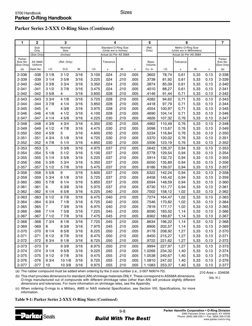
Parker O-Ring Handbook5700 Handbook Sizes
9-8
Build With The Best!SealsParker Hannifin Corporation • O-Ring Division
2360 Palumbo Drive, Lexington, KY 40509Phone: (859) 269-2351 • Fax: (859) 335-5128
www.parker.com/o-ring
2-338 -338 3 1/8 3 1/2 3/16 3.100 .024 .210 .005 .3602 78,74 0,61 5,33 0,13 2-3382-339 -339 3 1/4 3 5/8 3/16 3.225 .024 .210 .005 .3738 81,92 0,61 5,33 0,13 2-3392-340 -340 3 3/8 3 3/4 3/16 3.350 .024 .210 .005 .3874 85,09 0,61 5,33 0,13 2-3402-341 -341 3 1/2 3 7/8 3/16 3.475 .024 .210 .005 .4010 88,27 0,61 5,33 0,13 2-3412-342 -342 3 5/8 4 3/16 3.600 .028 .210 .005 .4146 91,44 0,71 5,33 0,13 2-342
2-343 -343 3 3/4 4 1/8 3/16 3.725 .028 .210 .005 .4282 94,62 0,71 5,33 0,13 2-3432-344 -344 3 7/8 4 1/4 3/16 3.850 .028 .210 .005 .4418 97,79 0,71 5,33 0,13 2-3442-345 -345 4 4 3/8 3/16 3.975 .028 .210 .005 .4554 100,97 0,71 5,33 0,13 2-3452-346 -346 4 1/8 4 1/2 3/16 4.100 .028 .210 .005 .4690 104,14 0,71 5,33 0,13 2-3462-347 -347 4 1/4 4 5/8 3/16 4.225 .030 .210 .005 .4826 107,32 0,76 5,33 0,13 2-347
2-348 -348 4 3/8 4 3/4 3/16 4.350 .030 .210 .005 .4962 110,49 0,76 5,33 0,13 2-3482-349 -349 4 1/2 4 7/8 3/16 4.475 .030 .210 .005 .5098 113,67 0,76 5,33 0,13 2-3492-350 -350 4 5/8 5 3/16 4.600 .030 .210 .005 .5234 116,84 0,76 5,33 0,13 2-3502-351 -351 4 3/4 5 1/8 3/16 4.725 .030 .210 .005 .5370 120,02 0,76 5,33 0,13 2-3512-352 -352 4 7/8 5 1/4 3/16 4.850 .030 .210 .005 .5506 123,19 0,76 5,33 0,13 2-352
2-353 -353 5 5 3/8 3/16 4.975 .037 .210 .005 .5642 126,37 0,94 5,33 0,13 2-3532-354 -354 5 1/8 5 1/2 3/16 5.100 .037 .210 .005 .5778 129,54 0,94 5,33 0,13 2-3542-355 -355 5 1/4 5 5/8 3/16 5.225 .037 .210 .005 .5914 132,72 0,94 5,33 0,13 2-3552-356 -356 5 3/8 5 3/4 3/16 5.350 .037 .210 .005 .6050 135,89 0,94 5,33 0,13 2-3562-357 -357 5 1/2 5 7/8 3/16 5.475 .037 .210 .005 .6186 139,07 0,94 5,33 0,13 2-357
2-358 -358 5 5/8 6 3/16 5.600 .037 .210 .005 .6322 142,24 0,94 5,33 0,13 2-3582-359 -359 5 3/4 6 1/8 3/16 5.725 .037 .210 .005 .6458 145,42 0,94 5,33 0,13 2-3592-360 -360 5 7/8 6 1/4 3/16 5.850 .037 .210 .005 .6594 148,59 0,94 5,33 0,13 2-3602-361 -361 6 6 3/8 3/16 5.975 .037 .210 .005 .6730 151,77 0,94 5,33 0,13 2-3612-362 -362 6 1/4 6 5/8 3/16 6.225 .040 .210 .005 .7002 158,12 1,02 5,33 0,13 2-362
2-363 -363 6 1/2 6 7/8 3/16 6.475 .040 .210 .005 .7274 164,47 1,02 5,33 0,13 2-3632-364 -364 6 3/4 7 1/8 3/16 6.725 .040 .210 .005 .7546 170,82 1,02 5,33 0,13 2-3642-365 -365 7 7 3/8 3/16 6.975 .040 .210 .005 .7818 177,17 1,02 5,33 0,13 2-3652-366 -366 7 1/4 7 5/8 3/16 7.225 .045 .210 .005 .8090 183,52 1,14 5,33 0,13 2-3662-367 -367 7 1/2 7 7/8 3/16 7.475 .045 .210 .005 .8362 189,87 1,14 5,33 0,13 2-367
2-368 -368 7 3/4 8 1/8 3/16 7.725 .045 .210 .005 .8634 196,22 1,14 5,33 0,13 2-3682-369 -369 8 8 3/8 3/16 7.975 .045 .210 .005 .8906 202,57 1,14 5,33 0,13 2-3692-370 -370 8 1/4 8 5/8 3/16 8.225 .050 .210 .005 .9178 208,92 1,27 5,33 0,13 2-3702-371 -371 8 1/2 8 7/8 3/16 8.475 .050 .210 .005 .9450 215,27 1,27 5,33 0,13 2-3712-372 -372 8 3/4 9 1/8 3/16 8.725 .050 .210 .005 .9722 221,62 1,27 5,33 0,13 2-372
2-373 -373 9 9 3/8 3/16 8.975 .050 .210 .005 .9994 227,97 1,27 5,33 0,13 2-3732-374 -374 9 1/4 9 5/8 3/16 9.225 .055 .210 .005 1.0266 234,32 1,40 5,33 0,13 2-3742-375 -375 9 1/2 9 7/8 3/16 9.475 .055 .210 .005 1.0538 240,67 1,40 5,33 0,13 2-3752-376 -376 9 3/4 10 1/8 3/16 9.725 .055 .210 .005 1.0810 247,02 1,40 5,33 0,13 2-3762-377 -377 10 10 3/8 3/16 9.975 .055 .210 .005 1.1083 253,37 1,40 5,33 0,13 2-377
.210 Area = .034636
(sq. in.)
1 2 3 4 5 6 7Size Nominal Standard O-Ring Size (Ref. Metric O-Ring SizeOnly Size (Units are in Inches) Only) (Units are in Millimeters)
(Size Only) (Inches) Actual (b) Per AS 568A Actual (b) Per AS 568A
Parker ParkerSize No. AS 568A (Ref. Only) Tolerance Basic Tolerance Size No.
(Size Only) Uniform Volume (Size Only)
(a) Dash No. I.D. O.D. W. I.D. ± W ± Cu. In. I.D. ± W ± (a)
Parker Series 2-XXX O-Ring Sizes (Continued)
(a) The rubber compound must be added when ordering by the 2-size number (i.e., 2-007 N0674-70).
(b) This chart provides dimensions for standard (AN) shrinkage materials ONLY. These correspond to AS568A dimensions.O-rings manufactured out of compounds with different shrinkage rates (other than AN) will produce slightly differentdimensions and tolerances. For more information on shrinkage rates, see the Appendix.
(c) When ordering O-rings to a Military, AMS or NAS material Specification, see Section VIII, Specifications, for moreinformation.
Table 9-1: Parker Series 2-XXX O-Ring Sizes (Continued)

Parker O-Ring Handbook5700 Handbook Sizes
9-9
Build With The Best!SealsParker Hannifin Corporation • O-Ring Division
2360 Palumbo Drive, Lexington, KY 40509Phone: (859) 269-2351 • Fax: (859) 335-5128
www.parker.com/o-ring
2-378 -378 10 1/2 10 7/8 3/16 10.475 .060 .210 .005 1.1627 266,07 1,52 5,33 0,13 2-3782-379 -379 11 11 3/8 3/16 10.975 .060 .210 .005 1.2171 278,77 1,52 5,33 0,13 2-3792-380 -380 11 1/2 11 7/8 3/16 11.475 .065 .210 .005 1.2715 291,47 1,65 5,33 0,13 2-3802-381 -381 12 12 3/8 3/16 11.975 .065 .210 .005 1.3259 304,17 1,65 5,33 0,13 2-3812-382 -382 13 13 3/8 3/16 12.975 .065 .210 .005 1.4347 329,57 1,65 5,33 0,13 2-382
2-383 -383 14 14 3/8 3/16 13.975 .070 .210 .005 1.5435 354,97 1,78 5,33 0,13 2-3832-384 -384 15 15 3/8 3/16 14.975 .070 .210 .005 1.6523 380,37 1,78 5,33 0,13 2-3842-385 -385 16 16 3/8 3/16 15.955 .075 .210 .005 1.7590 405,26 1,91 5,33 0,13 2-3852-386 -386 17 17 3/8 3/16 16.955 .080 .210 .005 1.8678 430,66 2,03 5,33 0,13 2-3862-387 -387 18 18 3/8 3/16 17.955 .085 .210 .005 1.9766 456,06 2,16 5,33 0,13 2-387
2-388 -388 19 19 3/8 3/16 18.955 .090 .210 .005 2.0854 481,41 2,29 5,33 0,13 2-3882-389 -389 20 20 3/8 3/16 19.955 .095 .210 .005 2.1942 506,81 2,41 5,33 0,13 2-3892-390 -390 21 21 3/8 3/16 20.955 .095 .210 .005 2.3030 532,21 2,41 5,33 0,13 2-3902-391 -391 22 22 3/8 3/16 21.955 .100 .210 .005 2.4118 557,61 2,54 5,33 0,13 2-3912-392 -392 23 23 3/8 3/16 22.940 .105 .210 .005 2.5190 582,68 2,67 5,33 0,13 2-392
2-393 -393 24 24 3/8 3/16 23.940 .110 .210 .005 2.6278 608,08 2,79 5,33 0,13 2-3932-394 -394 25 25 3/8 3/16 24.940 .115 .210 .005 2.7366 633,48 2,92 5,33 0,13 2-3942-395 -395 26 26 3/8 3/16 25.940 .120 .210 .005 2.8454 658,88 3,05 5,33 0,13 2-3952-425 -425 4 1/2 5 1/4 4.475 .033 .275 .006 .8863 113,67 0,84 6,99 0,15 2-4252-426 -426 4 5/8 5 1/8 1/4 4.600 .033 .275 .006 .9097 116,84 0,84 6,99 0,15 2-426
2-427 -427 4 3/4 5 1/4 1/4 4.725 .033 .275 .006 .9330 120,02 0,84 6,99 0,15 2-4272-428 -428 4 7/8 5 3/8 1/4 4.850 .033 .275 .006 .9563 123,19 0,84 6,99 0,15 2-4282-429 -429 5 5 1/2 1/4 4.975 .037 .275 .006 .9796 126,37 0,94 6,99 0,15 2-4292-430 -430 5 1/8 5 5/8 1/4 5.100 .037 .275 .006 1.0030 129,54 0,94 6,99 0,15 2-4302-431 -431 5 1/4 5 3/4 1/4 5.225 .037 .275 .006 1.0263 132,72 0,94 6,99 0,15 2-431
2-432 -432 5 3/8 5 7/8 1/4 5.350 .037 .275 .006 1.0496 135,89 0,94 6,99 0,15 2-4322-433 -433 5 1/2 6 1/4 5.475 .037 .275 .006 1.0729 139,07 0,94 6,99 0,15 2-4332-434 -434 5 5/8 6 1/8 1/4 5.600 .037 .275 .006 1.0963 142,24 0,94 6,99 0,15 2-4342-435 -435 5 3/4 6 1/4 1/4 5.725 .037 .275 .006 1.1196 145,42 0,94 6,99 0,15 2-4352-436 -436 5 7/8 6 3/8 1/4 5.850 .037 .275 .006 1.1429 148,59 0,94 6,99 0,15 2-436
2-437 -437 6 6 1/2 1/4 5.975 .037 .275 .006 1.1662 151,77 0,94 6,99 0,15 2-4372-438 -438 6 1/4 6 3/4 1/4 6.225 .040 .275 .006 1.2129 158,12 1,02 6,99 0,15 2-4382-439 -439 6 1/2 7 1/4 6.475 .040 .275 .006 1.2595 164,47 1,02 6,99 0,15 2-4392-440 -440 6 3/4 7 1/4 1/4 6.725 .040 .275 .006 1.3062 170,82 1,02 6,99 0,15 2-4402-441 -441 7 7 1/2 1/4 6.975 .040 .275 .006 1.3528 177,17 1,02 6,99 0,15 2-441
2-442 -442 7 1/4 7 3/4 1/4 7.225 .045 .275 .006 1.3995 183,52 1,14 6,99 0,15 2-4422-443 -443 7 1/2 8 1/4 7.475 .045 .275 .006 1.4461 189,87 1,14 6,99 0,15 2-4432-444 -444 7 3/4 8 1/4 1/4 7.725 .045 .275 .006 1.4928 196,22 1,14 6,99 0,15 2-4442-445 -445 8 8 1/2 1/4 7.975 .045 .275 .006 1.5394 202,57 1,14 6,99 0,15 2-4452-446 -446 8 1/2 9 1/4 8.475 .055 .275 .006 1.6327 215,27 1,40 6,99 0,15 2-446
.210 Area = .034636
.275 Area = .059396
(sq. in.)
1 2 3 4 5 6 7Size Nominal Standard O-Ring Size (Ref. Metric O-Ring SizeOnly Size (Units are in Inches) Only) (Units are in Millimeters)
(Size Only) (Inches) Actual (b) Per AS 568A Actual (b) Per AS 568A
Parker ParkerSize No. AS 568A (Ref. Only) Tolerance Basic Tolerance Size No.
(Size Only) Uniform Volume (Size Only)
(a) Dash No. I.D. O.D. W. I.D. ± W ± Cu. In. I.D. ± W ± (a)
Parker Series 2-XXX O-Ring Sizes (Continued)
(a) The rubber compound must be added when ordering by the 2-size number (i.e., 2-007 N0674-70).
(b) This chart provides dimensions for standard (AN) shrinkage materials ONLY. These correspond to AS568A dimensions.O-rings manufactured out of compounds with different shrinkage rates (other than AN) will produce slightly differentdimensions and tolerances. For more information on shrinkage rates, see the Appendix.
(c) When ordering O-rings to a Military, AMS or NAS material Specification, see Section VIII, Specifications, for moreinformation.
Table 9-1: Parker Series 2-XXX O-Ring Sizes (Continued)

Parker O-Ring Handbook5700 Handbook Sizes
9-10
Build With The Best!SealsParker Hannifin Corporation • O-Ring Division
2360 Palumbo Drive, Lexington, KY 40509Phone: (859) 269-2351 • Fax: (859) 335-5128
www.parker.com/o-ring
2-447 -447 9 9 1/2 1/4 8.975 .055 .275 .006 1.7260 227,97 1,40 6,99 0,15 2-4472-448 -448 9 1/2 10 1/4 9.475 .055 .275 .006 1.8193 240,67 1,40 6,99 0,15 2-4482-449 -449 10 10 1/2 1/4 9.975 .055 .275 .006 1.9126 253,37 1,40 6,99 0,15 2-4492-450 -450 10 1/2 11 1/4 10.475 .060 .275 .006 2.0059 266,07 1,52 6,99 0,15 2-4502-451 -451 11 11 1/2 1/4 10.975 .060 .275 .006 2.0992 278,77 1,52 6,99 0,15 2-451
2-452 -452 11 1/2 12 1/4 11.475 .060 .275 .006 2.1925 291,47 1,52 6,99 0,15 2-4522-453 -453 12 12 1/2 1/4 11.975 .060 .275 .006 2.2858 304,17 1,52 6,99 0,15 2-4532-454 -454 12 1/2 13 1/4 12.475 .060 .275 .006 2.3791 316,87 1,52 6,99 0,15 2-4542-455 -455 13 13 1/2 1/4 12.975 .060 .275 .006 2.4724 329,57 1,52 6,99 0,15 2-4552-456 -456 13 1/2 14 1/4 13.475 .070 .275 .006 2.5657 342,27 1,78 6,99 0,15 2-456
2-457 -457 14 14 1/2 1/4 13.975 .070 .275 .006 2.6590 354,97 1,78 6,99 0,15 2-4572-458 -458 14 1/2 15 1/4 14.475 .070 .275 .006 2.7523 367,67 1,78 6,99 0,15 2-4582-459 -459 15 15 1/2 1/4 14.975 .070 .275 .006 2.8456 380,37 1,78 6,99 0,15 2-4592-460 -460 15 1/2 16 1/4 15.475 .070 .275 .006 2.9389 393,07 1,78 6,99 0,15 2-4602-461 -461 16 16 1/2 1/4 15.955 .075 .275 .006 3.0285 405,26 1,91 6,99 0,15 2-461
2-462 -462 16 1/2 17 1/4 16.455 .075 .275 .006 3.1218 417,96 1,91 6,99 0,15 2-4622-463 -463 17 17 1/2 1/4 16.955 .080 .275 .006 3.2151 430,66 2,03 6,99 0,15 2-4632-464 -464 17 1/2 18 1/4 17.455 .085 .275 .006 3.3084 443,36 2,16 6,99 0,15 2-4642-465 -465 18 18 1/2 1/4 17.955 .085 .275 .006 3.4017 456,06 2,16 6,99 0,15 2-4652-466 -466 18 1/2 19 1/4 18.455 .085 .275 .006 3.4950 468,76 2,16 6,99 0,15 2-466
2-467 -467 19 19 1/2 1/4 18.955 .090 .275 .006 3.5883 481,46 2,29 6,99 0,15 2-4672-468 -468 19 1/2 20 1/4 19.455 .090 .275 .006 3.6816 494,16 2,29 6,99 0,15 2-4682-469 -469 20 20 1/2 1/4 19.955 .095 .275 .006 3.7749 506,86 2,41 6,99 0,15 2-4692-470 -470 21 21 1/2 1/4 20.955 .095 .275 .006 3.9615 532,26 2,41 6,99 0,15 2-4702-471 -471 22 22 1/2 1/4 21.955 .100 .275 .006 4.1481 557,66 2,54 6,99 0,15 2-471
2-472 -472 23 23 1/2 1/4 22.940 .105 .275 .006 4.3319 582,68 2,67 6,99 0,15 2-4722-473 -473 24 24 1/2 1/4 23.940 .110 .275 .006 4.5185 608,08 2,79 6,99 0,15 2-4732-474 -474 25 25 1/2 1/4 24.940 .115 .275 .006 4.7051 633,48 2,92 6,99 0,15 2-4742-475 -475 26 26 1/2 1/4 25.940 .120 .275 .006 4.8917 658,88 3,05 6,99 0,15 2-475
.275 Area = .059396
(sq. in.)
1 2 3 4 5 6 7Size Nominal Standard O-Ring Size (Ref. Metric O-Ring SizeOnly Size (Units are in Inches) Only) (Units are in Millimeters)
(Size Only) (Inches) Actual (b) Per AS 568A Actual (b) Per AS 568A
Parker ParkerSize No. AS 568A (Ref. Only) Tolerance Basic Tolerance Size No.
(Size Only) Uniform Volume (Size Only)
(a) Dash No. I.D. O.D. W. I.D. ± W ± Cu. In. I.D. ± W ± (a)
Parker Series 2-XXX O-Ring Sizes (Continued)
(a) The rubber compound must be added when ordering by the 2-size number (i.e., 2-007 N0674-70).
(b) This chart provides dimensions for standard (AN) shrinkage materials ONLY. These correspond to AS568A dimensions.O-rings manufactured out of compounds with different shrinkage rates (other than AN) will produce slightly differentdimensions and tolerances. For more information on shrinkage rates, see the Appendix.
(c) When ordering O-rings to a Military, AMS or NAS material Specification, see Section VIII, Specifications, for moreinformation.
Table 9-1: Parker Series 2-XXX O-Ring Sizes (Continued)

Parker O-Ring Handbook5700 Handbook Sizes
9-11
Build With The Best!SealsParker Hannifin Corporation • O-Ring Division
2360 Palumbo Drive, Lexington, KY 40509Phone: (859) 269-2351 • Fax: (859) 335-5128
www.parker.com/o-ring
(a) The rubber compound must be added when ordering by the 3-size number (i.e.,3-910 N552-90).
(b) This chart provides dimensions for standard (AN) shrinkage materials ONLY. These correspond toAS568A dimensions. O-rings manufactured out of compounds with different shrinkage rates (other thanAN) will produce slightly different dimensions and tolerances. For more information on shrinkage rates,see the Appendix.
Table 9-2: Parker Series 3-XXX O-Rings Sizes
Parker Series 3-XXX O-Ring Sizes
These O-rings are intended for use with internal straight thread fluid connection bosses and tube fittings. Ref. MS33656,MS33657, SAE straight thread O-ring boss and mating swivel and adjustable style fittings.
3-901 -901 3/32 .185 .005 .056 .003 .0019 4,70 0,13 1,42 0,08 3-9013-902 -902 1/8 .239 .005 .064 .003 .0031 6,07 0,13 1,63 0,08 3-9023-903 -903 3/16 .301 .005 .064 .003 .0037 7,65 0,13 1,63 0,08 3-9033-904 -904 1/4 .351 .005 .072 .003 .0055 8,92 0,13 1,83 0,08 3-9043-905 -905 5/16 .414 .005 .072 .003 .0063 10,52 0,13 1,83 0,08 3-905
3-906 -906 3/8 .468 .005 .078 .003 .0082 11,89 0,13 1,98 0,08 3-9063-907 -907 7/16 .530 .007 .082 .003 .0102 13,46 0,18 2,08 0,08 3-9073-908 -908 1/2 .644 .009 .087 .003 .0137 16,36 0,23 2,21 0,08 3-9083-909 -909 9/16 .706 .009 .097 .003 .0187 17,93 0,23 2,46 0,08 3-9093-910 -910 5/8 .755 .009 .097 .003 .0198 19,18 0,23 2,46 0,08 3-910
3-911 -911 11/16 .863 .009 .116 .004 .0326 21,92 0,23 2,95 0,10 3-9113-912 -912 3/4 .924 .009 .116 .004 .0346 23,47 0,23 2,95 0,10 3-9123-913 -913 13/16 .986 .010 .116 .004 .0366 25,04 0,26 2,95 0,10 3-9133-914 -914 7/8 1.047 .010 .116 .004 .0387 26,59 0,26 2,95 0,10 3-9143-916 -916 1 1.171 .010 .116 .004 .0428 29,74 0,26 2,95 0,10 3-916
3-918 -918 1 1/8 1.355 .012 .116 .004 .0489 34,42 0,30 2,95 0,10 3-9183-920 -920 1 1/4 1.475 .014 .118 .004 .0548 37,47 0,36 3,00 0,10 3-9203-924 -924 1 1/2 1.720 .014 .118 .004 .0632 43,69 0,36 3,00 0,10 3-9243-928 -928 1 3/4 2.090 .018 .118 .004 .0759 53,09 0,46 3,00 0,10 3-9283-932 -932 2 2.337 .018 .118 .004 .0844 59,36 0,46 3,00 0,10 3-932
1 2 3 4 5 6 7 8 9 10 11O-Ring Size — Actual (b) per AS568A Metric O-Ring Size per AS568A (b)
(Units are in Inches) (Units are in Millimeters)
3-XXX (a) AS568A Tube O.D. Basic 3-XXX (a)Dash Tolerance Volume Tolerance
Size No. No. (Ref.) I.D. ± W ± (cu. in.) I.D. ± W ± Size No.
.056 Area = .00246
.064 Area = .00322
.072 Area = .00407
.078 Area = .00478
.082 Area = .00528
.087 Area = .00594
.097 Area = .00739
.116 Area = .01057
.118 Area = .01094(sq. in.)

Parker O-Ring Handbook5700 Handbook Sizes
9-12
Build With The Best!SealsParker Hannifin Corporation • O-Ring Division
2360 Palumbo Drive, Lexington, KY 40509Phone: (859) 269-2351 • Fax: (859) 335-5128
www.parker.com/o-ring
Parker Series 5-XXX O-Ring Sizes
Std Inches Metric Millimeters5-Size I.D. Tol ± W Tol ± 5-Size I.D. Tol ± W Tol ±
Std Inches Metric Millimeters5-Size I.D. Tol ± W Tol ± 5-Size I.D. Tol ± W Tol ±
The following 5-XXX sizes are O-rings of nonstandarddimensions for which Parker tooling was available as ofNovember 1, 1997. This tooling will be maintained whilevolume demand continues. A mold scrapped as defectivewill not be replaced unless demand justifies the expense.
Note: These molds are cut to allow for standard “AN”shrinkage, and in materials having standard shrinkage theywill normally produce rings to the dimensions listed. Ma-terials with other than standard shrinkage will give differ-ent dimensions and tolerances. Please consult the factory oryour local Parker Distributor for the availability of specialsizes not included in this list as of this writing.
(a) The rubber compound must be added when ordering by the 5-size number (i.e., 5-007 N0674-70).(b) This chart provides dimensions for standard (AN) shrinkage materials ONLY. These correspond to AS568A dimensions. O-rings manufactured
out of compounds with different shrinkage rates (other than AN) will produce slightly different dimensions and tolerances. For more informationon shrinkage rates, see the Appendix.
Table 9-3: Parker Series 5-XXX O-Rings Size Cross Reference Table
5-118 .059 .004 .040 .003 5-118 1.50 0.10 1.02 .085-187 .070 .005 .036 .003 5-187 1.78 0.13 0.91 .085-051 .070 .005 .040 .003 5-051 1.78 0.13 1.02 .085-101 .100 .005 .038 .003 5-101 2.54 0.13 0.97 .085-578 .102 .005 .074 .003 5-578 2.59 0.13 1.88 .08
5-632 .110 .005 .040 .003 5-632 2.79 0.13 1.02 .085-102 .116 .005 .038 .003 5-102 2.95 0.13 0.97 .085-178 .120 .005 .040 .003 5-178 3.05 0.13 1.02 .085-683 .122 .005 .063 .003 5-683 3.10 0.13 1.60 .085-646 .126 .005 .040 .003 5-646 3.20 0.13 1.02 .08
5-103 .128 .005 .050 .003 5-103 3.25 0.13 1.27 .085-190 .132 .005 .070 .003 5-190 3.35 0.13 1.78 .085-579 .133 .005 .074 .003 5-579 3.39 0.13 1.88 .085-669 .146 .005 .040 .003 5-669 3.71 0.13 1.02 .085-148 .154 .005 .038 .003 5-148 3.91 0.13 0.97 .08
5-105 .154 .005 .050 .003 5-105 3.91 0.13 1.27 .085-106 .154 .005 .066 .003 5-106 3.91 0.13 1.68 .085-580 .165 .005 .074 .003 5-580 4.19 0.13 1.88 .085-193 .176 .005 .040 .003 5-193 4.47 0.13 1.02 .085-108 .176 .005 .050 .003 5-108 4.47 0.13 1.27 .08
5-124 .176 .005 .056 .003 5-124 4.47 0.13 1.42 .085-107 .176 .005 .066 .003 5-107 4.47 0.13 1.68 .085-125 .180 .005 .040 .003 5-125 4.57 0.13 1.02 .085-581 .192 .005 .074 .003 5-581 4.88 0.13 1.88 .085-685 .208 .005 .094 .003 5-685 5.28 0.13 2.39 .08
5-582 .224 .005 .074 .003 5-582 5.69 0.13 1.88 .085-194 .228 .005 .040 .003 5-194 5.79 0.13 1.02 .085-638 .233 .005 .076 .003 5-638 5.92 0.13 1.93 .085-179 .239 .005 .040 .003 5-179 6.07 0.13 1.02 .085-151 .239 .005 .051 .003 5-151 6.07 0.13 1.30 .08
5-127 .239 .005 .074 .003 5-127 6.07 0.13 1.88 .085-1002 .239 .005 .174 .005 5-1002 6.07 0.13 4.42 .135-197 .242 .005 .040 .003 5-197 6.15 0.13 1.02 .085-180 .248 .005 .048 .003 5-180 6.30 0.13 1.22 .085-686 .248 .005 .094 .003 5-686 6.30 0.13 2.39 .08
5-583 .251 .005 .074 .003 5-583 6.38 0.13 1.88 .085-200 .265 .005 .139 .004 5-200 6.73 0.13 3.53 .105-052 .270 .005 .070 .003 5-052 6.86 0.13 1.78 .085-202 .278 .005 .046 .003 5-202 7.06 0.13 1.17 .085-698 .283 .005 .040 .003 5-698 7.19 0.13 1.02 .08
5-584 .283 .005 .074 .003 5-584 7.19 0.13 1.88 .085-687 .287 .005 .094 .003 5-687 7.29 0.13 2.39 .085-1004 .290 .005 .045 .003 5-1004 7.39 0.13 1.14 .085-152 .301 .005 .025 .003 5-152 7.65 0.13 0.64 .085-056 .301 .005 .038 .003 5-056 7.65 0.13 0.97 .08
5-710 .301 .005 .054 .003 5-710 7.65 0.13 1.37 .085-673 .305 .005 .074 .003 5-673 7.75 0.13 1.88 .085-204 .312 .005 .036 .003 5-204 7.92 0.13 0.91 .08
5-205 .312 .005 .092 .003 5-205 7.92 0.13 2.34 .085-160 .312 .005 .103 .003 5-160 7.92 0.13 2.62 .085-712 .313 .005 .051 .003 5-712 7.95 0.13 1.30 .085-585 .314 .005 .074 .003 5-585 7.98 0.13 1.88 .085-664 .320 .005 .070 .003 5-664 8.13 0.13 1.78 .08
5-1006 .322 .005 .070 .003 5-1006 8.18 0.13 1.78 .085-206 .326 .005 .103 .003 5-206 8.28 0.13 2.62 .085-1007 .330 .005 .050 .003 5-1007 8.38 0.13 1.27 .085-133 .332 .005 .031 .003 5-133 8.43 0.13 0.79 .085-612 .344 .005 .070 .003 5-612 8.74 0.13 1.78 .08
5-586 .350 .005 .074 .003 5-586 8.89 0.13 1.88 .085-587 .350 .005 .106 .004 5-587 8.89 0.13 2.69 .105-018 .352 .005 .113 .004 5-018 8.94 0.13 2.87 .105-699 .353 .005 .094 .003 5-699 8.97 0.13 2.39 .085-700 .354 .005 .118 .004 5-700 8.99 0.13 3.00 .10
5-716 .362 .005 .118 .004 5-716 9.19 0.13 3.00 .105-057 .364 .005 .045 .003 5-057 9.25 0.13 1.14 .085-209 .370 .005 .040 .003 5-209 9.40 0.13 1.02 .085-211 .375 .005 .187 .005 5-211 9.53 0.13 4.75 .135-212 .384 .005 .070 .003 5-212 9.75 0.13 1.78 .08
5-614 .391 .005 .103 .003 5-614 9.93 0.13 2.62 .085-718 .395 .005 .040 .003 5-718 10.03 0.13 1.02 .085-134 .410 .005 .031 .003 5-134 10.41 0.13 0.79 .085-588 .413 .005 .106 .004 5-588 10.49 0.13 2.69 .105-002 .416 .005 .059 .003 5-002 10.57 0.13 1.50 .08
5-215 .418 .005 .094 .003 5-215 10.62 0.13 2.39 .085-218 .425 .005 .025 .003 5-218 10.80 0.13 0.64 .085-682 .426 .005 .040 .003 5-682 10.82 0.13 1.02 .085-058 .426 .005 .050 .003 5-058 10.82 0.13 1.27 .085-613 .437 .005 .070 .003 5-613 11.10 0.13 1.78 .08
5-1011 .447 .005 .103 .003 5-1011 11.35 0.13 2.62 .085-222 .455 .005 .128 .004 5-222 11.56 0.13 3.25 .105-223 .458 .005 .053 .003 5-223 11.63 0.13 1.35 .085-225 .469 .006 .094 .003 5-225 11.91 0.15 2.39 .085-615 .469 .006 .103 .003 5-615 11.91 0.15 2.62 .15
5-725 .470 .006 .270 .006 5-725 11.94 0.15 6.86 .155-652 .473 .006 .071 .003 5-652 12.01 0.15 1.80 .085-726 .484 .006 .056 .003 5-726 12.29 0.15 1.42 .085-566 .489 .006 .055 .003 5-566 12.42 0.15 1.40 .085-230 .500 .006 .125 .004 5-230 12.70 0.15 3.18 .10
5-231 .501 .006 .062 .003 5-231 12.73 0.15 1.57 .085-675 .508 .006 .049 .003 5-675 12.90 0.15 1.24 .085-616 .516 .006 .103 .003 5-616 13.11 0.15 2.62 .085-1014 .525 .007 .071 .003 5-1014 13.34 0.18 1.80 .085-135 .526 .007 .031 .003 5-135 13.36 0.18 0.79 .08
5-590 .535 .007 .106 .004 5-590 13.59 0.18 2.69 .105-001 .547 .007 .051 .003 5-001 13.89 0.18 1.30 .085-162 .554 .007 .070 .003 5-162 14.07 0.18 1.78 .08
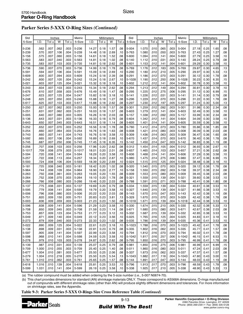
Parker O-Ring Handbook5700 Handbook Sizes
9-13
Build With The Best!SealsParker Hannifin Corporation • O-Ring Division
2360 Palumbo Drive, Lexington, KY 40509Phone: (859) 269-2351 • Fax: (859) 335-5128
www.parker.com/o-ring
Parker Series 5-XXX O-Ring Sizes (Continued)
Std Inches Metric Millimeters5-Size I.D. Tol ± W Tol ± 5-Size I.D. Tol ± W Tol ±
Std Inches Metric Millimeters5-Size I.D. Tol ± W Tol ± 5-Size I.D. Tol ± W Tol ±
5-236 .562 .007 .062 .003 5-236 14.27 0.18 1.57 .085-239 .570 .007 .106 .004 5-239 14.48 0.18 2.69 .105-156 .575 .007 .060 .003 5-156 14.61 0.18 1.52 .085-563 .583 .007 .040 .003 5-563 14.81 0.18 1.02 .085-735 .583 .007 .103 .003 5-735 14.81 0.18 2.62 .08
5-736 .590 .007 .070 .003 5-736 14.99 0.18 1.78 .085-591 .594 .007 .106 .004 5-591 15.09 0.18 2.69 .105-609 .600 .007 .094 .003 5-609 15.24 0.18 2.39 .085-242 .600 .007 .105 .004 5-242 15.24 0.18 2.67 .105-021 .603 .007 .125 .004 5-021 15.32 0.18 3.18 .10
5-243 .604 .007 .103 .003 5-243 15.34 0.18 2.62 .085-676 .610 .007 .058 .003 5-676 15.49 0.18 1.47 .085-247 .623 .007 .125 .004 5-247 15.82 0.18 3.18 .105-248 .625 .007 .050 .003 5-248 15.88 0.18 1.27 .085-617 .625 .007 .103 .003 5-617 15.88 0.18 2.62 .08
5-250 .627 .007 .062 .003 5-250 15.93 0.18 1.57 .085-251 .631 .007 .062 .003 5-251 16.03 0.18 1.57 .085-005 .640 .007 .080 .003 5-005 16.26 0.18 2.03 .085-136 .643 .007 .031 .003 5-136 16.33 0.18 0.79 .085-643 .650 .007 .045 .003 5-643 16.51 0.18 1.14 .08
5-252 .652 .007 .070 .003 5-252 16.56 0.18 1.78 .085-254 .660 .007 .064 .003 5-254 16.76 0.18 1.63 .085-743 .660 .007 .141 .004 5-743 16.76 0.18 3.58 .105-592 .665 .007 .106 .004 5-592 16.89 0.18 2.69 .105-745 .687 .007 .250 .006 5-745 17.45 0.18 6.35 .15
5-256 .707 .008 .103 .003 5-256 17.96 0.20 2.62 .085-1017 .709 .008 .079 .003 5-1017 18.01 0.20 2.01 .085-594 .720 .008 .141 .004 5-594 18.29 0.20 3.58 .105-257 .722 .008 .113 .004 5-257 18.34 0.20 2.87 .105-593 .724 .008 .106 .004 5-593 18.39 0.20 2.69 .10
5-181 .725 .008 .040 .003 5-181 18.42 0.20 1.02 .085-964 .744 .008 .109 .004 5-964 18.90 0.20 2.77 .105-263 .750 .008 .061 .003 5-263 19.05 0.20 1.55 .085-264 .752 .008 .070 .003 5-264 19.10 0.20 1.78 .085-266 .766 .008 .080 .003 5-266 19.46 0.20 2.03 .08
5-137 .775 .008 .031 .003 5-137 19.69 0.20 0.79 .085-595 .779 .008 .141 .004 5-595 19.79 0.20 3.58 .105-006 .796 .008 .080 .003 5-006 20.22 0.20 2.03 .085-751 .820 .009 .150 .005 5-751 20.83 0.23 3.81 .135-003 .836 .009 .059 .003 5-003 21.23 0.23 1.50 .08
5-596 .838 .009 .141 .004 5-596 21.29 0.23 3.58 .105-708 .850 .009 .045 .003 5-708 21.59 0.23 1.14 .085-753 .857 .009 .123 .004 5-753 21.77 0.23 3.12 .105-049 .871 .009 .140 .004 5-049 22.12 0.23 3.56 .105-273 .879 .009 .040 .003 5-273 22.33 0.23 1.02 .08
5-022 .890 .009 .125 .004 5-022 22.61 0.23 3.18 .105-138 .898 .009 .031 .003 5-138 22.81 0.23 0.79 .085-597 .905 .009 .141 .004 5-597 22.99 0.23 3.58 .105-598 .968 .010 .141 .004 5-598 24.59 0.25 3.58 .105-278 .979 .010 .103 .003 5-278 24.87 0.25 2.62 .08
5-139 .987 .010 .031 .003 5-139 25.07 0.25 0.79 .085-709 1.000 .010 .055 .003 5-709 25.40 0.25 1.40 .085-677 1.004 .010 .081 .003 5-677 25.50 0.25 2.06 .085-279 1.004 .010 .218 .005 5-279 25.50 0.25 5.54 .135-761 1.010 .010 .062 .003 5-761 25.65 0.25 1.57 .08
5-618 1.016 .010 .139 .004 5-618 25.81 0.25 3.53 .105-599 1.031 .010 .141 .004 5-599 26.19 0.25 3.58 .10
5-004 1.070 .010 .065 .003 5-004 27.18 0.25 1.65 .085-763 1.080 .010 .050 .003 5-763 27.43 0.25 1.27 .085-600 1.094 .010 .141 .004 5-600 27.79 0.25 3.58 .105-140 1.112 .010 .031 .003 5-140 28.24 0.25 0.79 .085-601 1.153 .012 .141 .004 5-601 29.29 0.30 3.58 .10
5-769 1.176 .012 .183 .005 5-769 29.87 0.30 4.65 .135-290 1.180 .012 .210 .005 5-290 29.97 0.30 5.33 .135-291 1.186 .012 .070 .003 5-291 30.12 0.30 1.78 .085-1028 1.190 .012 .250 .006 5-1028 30.23 0.30 6.35 .155-602 1.212 .012 .141 .004 5-602 30.78 0.30 3.58 .10
5-294 1.213 .012 .149 .004 5-294 30.81 0.30 3.78 .105-295 1.225 .012 .275 .006 5-295 31.12 0.30 6.99 .155-141 1.226 .012 .031 .003 5-141 31.14 0.30 0.79 .085-296 1.229 .012 .070 .003 5-296 31.22 0.30 1.78 .085-297 1.230 .012 .197 .005 5-297 31.24 0.30 5.00 .13
5-301 1.259 .012 .092 .003 5-301 31.98 0.30 2.34 .085-603 1.279 .012 .141 .004 5-603 32.49 0.30 3.58 .105-157 1.338 .012 .092 .003 5-157 33.99 0.30 2.34 .085-604 1.342 .012 .141 .004 5-604 34.09 0.30 3.58 .105-605 1.401 .014 .141 .004 5-605 35.59 0.36 3.58 .10
5-780 1.412 .014 .073 .003 5-780 35.86 0.36 1.85 .085-008 1.421 .014 .080 .003 5-008 36.09 0.36 2.03 .085-309 1.436 .014 .063 .003 5-309 36.47 0.36 1.60 .085-670 1.437 .014 .070 .003 5-670 36.40 0.36 1.78 .085-142 1.450 .014 .047 .003 5-142 36.83 0.36 1.19 .08
5-312 1.454 .014 .105 .004 5-312 36.93 0.36 2.67 .105-657 1.465 .014 .103 .003 5-657 37.21 0.36 2.62 .085-606 1.468 .014 .141 .004 5-606 37.29 0.36 3.58 .105-980 1.475 .014 .275 .006 5-980 37.47 0.36 6.99 .155-024 1.515 .015 .125 .004 5-024 38.48 0.38 3.18 .10
5-320 1.540 .015 .070 .003 5-320 39.12 0.38 1.78 .085-158 1.550 .015 .092 .003 5-158 39.37 0.38 2.34 .085-009 1.553 .015 .080 .003 5-009 39.45 0.38 2.03 .085-321 1.559 .015 .139 .004 5-321 39.60 0.38 3.53 .105-788 1.591 .015 .071 .003 5-788 40.41 0.38 1.80 .08
5-034 1.559 .015 .139 .004 5-034 40.61 0.38 3.53 .105-327 1.640 .015 .139 .004 5-327 41.66 0.38 3.53 .105-143 1.670 .015 .047 .003 5-143 42.42 0.38 1.19 .085-329 1.670 .015 .070 .003 5-329 42.42 0.38 1.78 .085-1018 1.671 .015 .139 .004 5-1018 42.44 0.38 3.53 .10
5-330 1.674 .015 .210 .005 5-330 42.52 0.38 5.33 .135-671 1.680 .015 .080 .003 5-671 42.67 0.38 2.03 .085-332 1.687 .015 .139 .004 5-332 42.85 0.38 3.53 .105-025 1.765 .016 .125 .004 5-025 44.83 0.41 3.18 .105-035 1.786 .016 .139 .004 5-035 45.36 0.41 3.53 .10
5-1023 1.788 .016 .070 .003 5-1023 45.42 0.41 1.78 .085-335 1.802 .016 .062 .003 5-335 45.77 0.41 1.57 .085-794 1.812 .016 .070 .003 5-794 46.02 0.41 1.78 .085-1042 1.817 .016 .257 .006 5-1042 46.15 0.41 6.53 .155-795 1.850 .016 .070 .003 5-795 46.99 0.41 1.78 .08
5-981 1.850 .016 .275 .006 5-981 46.99 0.41 6.99 .155-011 1.860 .016 .080 .003 5-011 47.24 0.41 2.03 .085-337 1.873 .016 .062 .003 5-337 47.57 0.41 1.57 .085-1043 1.882 .017 .118 .004 5-1043 47.80 0.43 3.00 .105-144 1.891 .017 .047 .003 5-144 48.03 0.43 1.19 .08
5-796 1.913 .017 .070 .003 5-796 48.59 0.43 1.78 .085-338 1.925 .017 .210 .005 5-338 48.90 0.43 5.33 .13
(a) The rubber compound must be added when ordering by the 5-size number (i.e., 5-007 N0674-70).(b) This chart provides dimensions for standard (AN) shrinkage materials ONLY. These correspond to AS568A dimensions. O-rings manufactured
out of compounds with different shrinkage rates (other than AN) will produce slightly different dimensions and tolerances. For more informationon shrinkage rates, see the Appendix.
Table 9-3: Parker Series 5-XXX O-Rings Size Cross Reference Table (Continued)
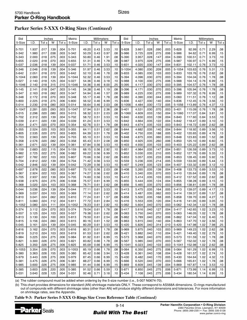
Parker O-Ring Handbook5700 Handbook Sizes
9-14
Build With The Best!SealsParker Hannifin Corporation • O-Ring Division
2360 Palumbo Drive, Lexington, KY 40509Phone: (859) 269-2351 • Fax: (859) 335-5128
www.parker.com/o-ring
5-701 1.937 .017 .139 .004 5-701 49.20 0.43 3.53 .105-342 1.980 .017 .038 .003 5-342 50.29 0.43 0.97 .085-343 2.000 .018 .075 .003 5-343 50.80 0.46 1.91 .085-655 2.020 .018 .070 .003 5-655 51.31 0.46 1.78 .085-037 2.036 .018 .139 .004 5-037 51.71 0.46 3.53 .10
5-346 2.046 .018 .139 .004 5-346 51.97 0.46 3.53 .105-642 2.051 .018 .070 .003 5-642 52.10 0.46 1.78 .085-1044 2.060 .018 .139 .004 5-1044 52.32 0.46 3.53 .105-027 2.140 .018 .125 .004 5-027 54.36 0.46 3.18 .105-1046 2.140 .018 .315 .010 5-1046 54.36 0.46 8.00 .25
5-145 2.141 .018 .047 .003 5-145 54.38 0.46 1.19 .085-347 2.163 .018 .062 .003 5-347 54.94 0.46 1.57 .085-348 2.172 .018 .070 .003 5-348 55.17 0.46 1.78 .085-800 2.225 .018 .275 .006 5-800 56.52 0.46 6.99 .155-014 2.230 .018 .080 .003 5-014 56.64 0.46 2.03 .08
5-1047 2.281 .020 .093 .003 5-1047 57.94 0.51 2.36 .085-015 2.296 .020 .080 .003 5-015 58.32 0.51 2.03 .085-702 2.312 .020 .139 .004 5-702 58.72 0.51 3.53 .105-039 2.411 .020 .139 .004 5-039 61.24 0.51 3.53 .105-354 2.471 .020 .070 .003 5-354 62.76 0.51 1.78 .08
5-355 2.524 .020 .103 .003 5-355 64.11 0.51 2.62 .085-805 2.535 .020 .070 .003 5-805 64.39 0.51 1.78 .085-703 2.563 .020 .139 .004 5-703 65.10 0.51 3.53 .105-358 2.576 .020 .082 .003 5-358 65.43 0.51 2.08 .085-361 2.671 .022 .139 .004 5-361 67.84 0.56 3.53 .10
5-159 2.683 .022 .115 .004 5-159 68.15 0.56 2.92 .105-982 2.725 .022 .275 .006 5-982 69.22 0.56 6.99 .155-807 2.782 .022 .103 .003 5-807 70.66 0.56 2.62 .085-704 2.812 .022 .139 .004 5-704 71.42 0.56 3.53 .105-042 2.846 .022 .139 .004 5-042 72.29 0.56 3.53 .10
5-697 2.878 .022 .080 .003 5-697 73.10 0.56 2.03 .085-367 2.924 .022 .103 .003 5-367 74.27 0.56 2.62 .085-705 2.937 .022 .139 .004 5-705 74.60 0.56 3.53 .105-938 2.975 .024 .275 .006 5-938 75.57 0.61 6.99 .155-368 3.020 .024 .103 .003 5-368 76.71 0.61 2.62 .08
5-044 3.036 .024 .139 .004 5-044 77.11 0.61 3.53 .105-369 3.037 .024 .103 .003 5-369 77.14 0.61 2.62 .085-810 3.041 .024 .062 .003 5-810 77.24 0.61 1.57 .085-811 3.060 .024 .112 .004 5-811 77.72 0.61 2.84 .105-1052 3.080 .024 .111 .004 5-1052 78.23 0.61 2.82 .10
5-374 3.112 .024 .070 .003 5-374 79.04 0.61 1.78 .085-557 3.125 .024 .103 .003 5-557 79.38 0.61 2.62 .085-813 3.130 .024 .100 .003 5-813 79.50 0.61 2.54 .085-815 3.156 .024 .060 .003 5-815 80.16 0.61 1.52 .085-045 3.161 .024 .139 .004 5-045 80.29 0.61 3.53 .10
5-816 3.162 .024 .070 .003 5-816 80.31 0.61 1.78 .085-819 3.210 .024 .103 .003 5-819 81.53 0.61 2.62 .085-984 3.225 .024 .275 .006 5-984 81.92 0.61 6.99 .155-821 3.300 .026 .070 .003 5-821 83.82 0.66 1.78 .085-825 3.350 .026 .275 .006 5-825 85.09 0.66 6.99 .15
5-1053 3.354 .026 .070 .003 5-1053 85.19 0.66 1.78 .085-380 3.363 .026 .155 .005 5-380 85.42 0.66 3.94 .135-979 3.443 .026 .275 .006 5-979 87.45 0.66 6.99 .155-381 3.475 .026 .275 .006 5-381 88.27 0.66 6.99 .155-985 3.600 .026 .275 .006 5-985 91.44 0.66 6.99 .15
5-385 3.603 .026 .220 .005 5-385 91.52 0.66 5.59 .135-031 3.640 .028 .125 .004 5-031 92.46 0.71 3.18 .10
5-828 3.661 .028 .090 .003 5-828 92.99 0.71 2.29 .085-986 3.725 .028 .275 .006 5-986 94.62 0.71 6.99 .155-390 3.957 .028 .147 .004 5-390 100.51 0.71 3.73 .105-987 3.975 .028 .275 .006 5-987 100.97 0.71 6.99 .155-831 4.020 .030 .147 .004 5-831 102.11 0.76 3.73 .10
5-1054 4.080 .030 .209 .005 5-1054 103.63 0.76 5.31 .135-833 4.085 .030 .103 .003 5-833 103.76 0.76 2.62 .085-394 4.096 .030 .070 .003 5-394 104.04 0.76 1.78 .085-988 4.100 .030 .275 .006 5-988 104.14 0.76 6.99 .155-395 4.117 .030 .070 .003 5-395 104.57 0.76 1.78 .08
5-396 4.171 .030 .070 .003 5-396 105.94 0.76 1.78 .085-989 4.225 .030 .275 .006 5-989 107.32 0.76 6.99 .155-060 4.390 .030 .044 .003 5-060 111.51 0.76 1.12 .085-836 4.427 .030 .140 .004 5-836 112.45 0.76 3.56 .105-1056 4.484 .030 .172 .005 5-1056 113.89 0.76 4.37 .13
5-401 4.531 .030 .070 .003 5-401 115.09 0.76 1.78 .085-1060 4.609 .033 .150 .004 5-1060 117.07 0.84 3.81 .105-840 4.630 .033 .139 .004 5-840 117.60 0.84 3.53 .105-842 4.664 .035 .122 .004 5-842 118.47 0.89 3.10 .105-843 4.674 .035 .103 .003 5-843 118.72 0.89 2.62 .08
5-844 4.682 .035 .140 .004 5-844 118.92 0.89 3.56 .105-402 4.750 .035 .188 .005 5-402 120.65 0.89 4.78 .135-848 4.875 .035 .060 .003 5-848 123.83 0.89 1.52 .085-850 4.925 .035 .260 .006 5-850 125.10 0.89 6.60 .155-403 4.930 .035 .103 .003 5-403 125.22 0.89 2.62 .08
5-851 4.984 .035 .147 .004 5-851 126.59 0.89 3.73 .105-852 5.030 .035 .210 .005 5-852 127.76 0.89 5.33 .135-853 5.057 .035 .233 .006 5-853 128.45 0.89 5.92 .155-559 5.236 .035 .214 .005 5-559 133.00 0.89 5.44 .135-407 5.249 .035 .123 .004 5-407 133.32 0.89 3.12 .10
5-408 5.265 .035 .139 .004 5-408 133.73 0.89 3.53 .105-410 5.340 .035 .070 .003 5-410 135.64 0.89 1.78 .085-412 5.414 .035 .103 .003 5-412 137.52 0.89 2.62 .085-855 5.444 .035 .124 .004 5-855 138.28 0.89 3.15 .105-856 5.465 .035 .070 .003 5-856 138.81 0.89 1.78 .08
5-413 5.475 .035 .164 .005 5-413 139.07 0.89 4.17 .135-414 5.487 .035 .062 .003 5-414 139.37 0.89 1.57 .085-858 5.500 .035 .168 .005 5-858 139.70 0.89 4.27 .135-416 5.553 .035 .120 .004 5-416 141.05 0.89 3.05 .105-062 5.604 .040 .070 .003 5-062 142.34 1.02 1.78 .08
5-417 5.616 .040 .127 .004 5-417 142.65 1.02 3.23 .105-063 5.750 .040 .070 .003 5-063 146.05 1.02 1.78 .085-862 5.789 .040 .252 .006 5-862 147.04 1.02 6.40 .155-863 5.815 .040 .140 .004 5-863 147.70 1.02 3.56 .105-420 5.826 .040 .314 .010 5-420 147.98 1.02 7.98 .25
5-969 5.875 .040 .103 .003 5-969 149.23 1.02 2.62 .085-421 5.882 .040 .110 .004 5-421 149.40 1.02 2.79 .105-573 5.968 .040 .070 .003 5-573 151.59 1.02 1.78 .085-567 5.985 .040 .070 .003 5-567 152.02 1.02 1.78 .085-1041 6.023 .040 .103 .003 5-1041 152.98 1.02 2.62 .08
5-064 6.350 .040 .275 .006 5-064 161.29 1.02 6.99 .155-428 6.361 .040 .108 .004 5-428 161.57 1.02 2.74 .105-430 6.482 .040 .170 .005 5-430 164.64 1.02 4.32 .135-666 6.520 .040 .070 .003 5-666 165.61 1.02 1.78 .085-869 6.609 .045 .139 .004 5-869 167.87 1.14 3.53 .10
5-871 6.850 .045 .275 .006 5-871 173.99 1.14 6.99 .155-434 7.108 .045 .275 .006 5-434 180.54 1.14 6.99 .15
Std Inches Metric Millimeters5-Size I.D. Tol ± W Tol ± 5-Size I.D. Tol ± W Tol ±
Std Inches Metric Millimeters5-Size I.D. Tol ± W Tol ± 5-Size I.D. Tol ± W Tol ±
Parker Series 5-XXX O-Ring Sizes (Continued)
(a) The rubber compound must be added when ordering by the 5-size number (i.e., 5-007 N0674-70).(b) This chart provides dimensions for standard (AN) shrinkage materials ONLY. These correspond to AS568A dimensions. O-rings manufactured
out of compounds with different shrinkage rates (other than AN) will produce slightly different dimensions and tolerances. For more informationon shrinkage rates, see the Appendix.
Table 9-3: Parker Series 5-XXX O-Rings Size Cross Reference Table (Continued)

Parker O-Ring Handbook5700 Handbook Sizes
9-15
Build With The Best!SealsParker Hannifin Corporation • O-Ring Division
2360 Palumbo Drive, Lexington, KY 40509Phone: (859) 269-2351 • Fax: (859) 335-5128
www.parker.com/o-ring
5-696 7.110 .045 .103 .003 5-696 180.59 1.14 2.62 .085-691 7.139 .045 .072 .003 5-691 181.33 1.14 1.83 .085-873 7.230 .045 .070 .003 5-873 183.64 1.14 1.78 .085-975 7.425 .045 .260 .006 5-975 188.60 1.14 6.60 .155-875 7.580 .050 .210 .005 5-875 192.53 1.27 5.33 .13
5-438 7.613 .050 .070 .003 5-438 193.37 1.27 1.78 .085-439 7.640 .050 .125 .004 5-439 194.06 1.27 3.18 .105-876 7.674 .050 .210 .005 5-876 194.92 1.27 5.33 .135-877 7.802 .050 .104 .003 5-877 198.17 1.27 2.64 .085-442 8.015 .050 .187 .005 5-442 203.58 1.27 4.75 .13
5-445 8.277 .050 .275 .006 5-445 210.24 1.27 6.99 .155-880 8.350 .050 .275 .006 5-880 212.09 1.27 6.99 .155-971 8.590 .050 .139 .004 5-971 218.19 1.27 3.53 .105-575 8.875 .055 .070 .003 5-575 225.42 1.40 1.78 .085-450 9.071 .055 .062 .003 5-450 230.40 1.40 1.57 .08
5-882 9.162 .055 .210 .005 5-882 232.72 1.40 5.33 .135-635 9.370 .055 .103 .003 5-635 238.00 1.40 2.62 .085-454 9.565 .055 .103 .003 5-454 242.95 1.40 2.62 .085-883 9.820 .060 .103 .003 5-883 249.43 1.52 2.62 .085-884 9.984 .060 .070 .003 5-884 253.59 1.52 1.78 .08
5-885 10.171 .060 .139 .004 5-885 258.34 1.52 3.53 .105-886 10.178 .060 .112 .004 5-886 258.52 1.52 2.84 .105-457 10.232 .060 .139 .004 5-457 259.89 1.52 3.53 .105-458 10.340 .060 .139 .004 5-458 262.64 1.52 3.53 .105-887 10.343 .060 .275 .006 5-887 262.71 1.52 6.99 .15
5-165 10.359 .060 .139 .004 5-165 263.12 1.52 3.53 .105-889 10.372 .060 .104 .003 5-889 263.45 1.52 2.64 .085-976 10.425 .060 .260 .006 5-976 264.80 1.52 6.60 .155-463 10.504 .060 .125 .004 5-463 266.80 1.52 3.18 .105-890 10.606 .060 .103 .003 5-890 269.39 1.52 2.62 .08
5-623 10.630 .060 .139 .004 5-623 270.00 1.52 3.53 .105-464 10.656 .060 .070 .003 5-464 270.66 1.52 1.78 .085-656 10.702 .060 .070 .003 5-656 271.83 1.52 1.78 .085-891 10.734 .060 .139 .004 5-891 272.64 1.52 3.53 .105-466 10.749 .060 .210 .005 5-466 273.03 1.52 5.33 .10
5-469 10.883 .060 .103 .003 5-469 276.43 1.52 2.62 .085-893 10.945 .060 .071 .003 5-893 278.00 1.52 1.80 .085-471 10.995 .060 .149 .004 5-471 279.27 1.52 3.78 .105-894 10.996 .060 .103 .003 5-894 279.30 1.52 2.62 .105-474 11.331 .060 .275 .006 5-474 287.81 1.52 6.99 .15
5-898 11.335 .060 .103 .003 5-898 287.91 1.52 2.62 .085-476 11.562 .070 .275 .006 5-476 293.67 1.78 6.99 .155-650 11.570 .070 .210 .005 5-650 293.88 1.78 5.33 .135-069 11.750 .070 .139 .004 5-069 298.45 1.78 3.53 .105-478 11.860 .070 .139 .004 5-478 301.24 1.78 3.53 .10
5-576 12.000 .070 .159 .005 5-576 304.80 1.78 4.04 .135-900 12.000 .070 .187 .005 5-900 304.80 1.78 4.75 .135-480 12.017 .070 .285 .006 5-480 305.23 1.78 7.24 .155-482 12.109 .070 .139 .004 5-482 307.57 1.78 3.53 .105-164 12.160 .070 .210 .005 5-164 308.86 1.78 5.33 .13
5-901 12.234 .070 .139 .004 5-901 310.74 1.78 3.53 .105-484 12.250 .070 .150 .005 5-484 311.15 1.78 3.81 .135-485 12.260 .070 .139 .004 5-485 311.40 1.78 3.53 .105-486 12.299 .070 .137 .004 5-486 312.39 1.78 3.48 .105-902 12.360 .070 .210 .005 5-902 313.94 1.78 5.33 .13
5-487 12.380 .070 .139 .004 5-487 314.45 1.78 3.53 .105-488 12.463 .070 .103 .003 5-488 316.56 1.78 2.62 .08
5-569 12.475 .070 .139 .004 5-569 316.87 1.78 3.53 .105-905 12.623 .070 .140 .004 5-905 320.62 1.78 3.56 .105-906 12.705 .070 .070 .003 5-906 322.71 1.78 1.78 .085-907 12.725 .070 .275 .006 5-907 323.22 1.78 6.99 .155-908 12.840 .070 .139 .004 5-908 326.14 1.78 3.53 .10
5-611 12.900 .070 .159 .005 5-611 327.66 1.78 4.04 .135-619 12.915 .070 .139 .004 5-619 328.04 1.78 3.53 .105-570 13.002 .070 .139 .004 5-570 330.25 1.78 3.53 .105-492 13.248 .070 .139 .004 5-492 336.50 1.78 3.53 .105-070 13.270 .070 .139 .004 5-070 337.06 1.78 3.53 .10
5-910 13.375 .070 .210 .005 5-910 339.73 1.78 5.33 .135-071 13.410 .070 .139 .004 5-071 340.61 1.78 3.53 .105-072 13.460 .070 .210 .005 5-072 341.88 1.78 5.33 .135-493 13.490 .070 .139 .004 5-493 342.65 1.78 3.53 .105-494 13.541 .070 .210 .005 5-494 343.94 1.78 5.33 .13
5-495 13.601 .070 .139 .004 5-495 345.47 1.78 3.53 .105-496 13.616 .070 .141 .004 5-496 345.85 1.78 3.58 .105-498 13.650 .070 .139 .004 5-498 346.71 1.78 3.53 .105-500 13.718 .070 .275 .006 5-500 348.44 1.78 6.48 .155-912 13.734 .070 .139 .004 5-912 348.84 1.78 3.53 .10
5-1097 13.750 .070 .103 .003 5-1097 349.25 1.78 2.62 .085-073 13.820 .080 .139 .004 5-073 351.03 2.03 3.53 .105-564 14.062 .080 .139 .004 5-564 357.17 2.03 3.53 .105-502 14.088 .080 .210 .005 5-502 357.84 2.03 5.33 .135-624 14.111 .080 .139 .004 5-624 358.42 2.03 3.53 .10
5-074 14.234 .080 .139 .004 5-074 361.54 2.03 3.53 .105-916 14.369 .080 .278 .006 5-916 364.97 2.03 7.06 .155-504 14.430 .080 .139 .004 5-504 366.52 2.03 3.53 .105-626 14.470 .080 .087 .003 5-626 367.54 2.03 2.21 .085-505 14.470 .080 .139 .004 5-505 367.54 2.03 3.53 .10
5-506 14.570 .080 .141 .004 5-506 370.08 2.03 3.58 .105-507 14.600 .080 .210 .005 5-507 370.84 2.03 5.33 .135-508 14.674 .080 .139 .004 5-508 372.72 2.03 3.53 .105-166 14.722 .080 .139 .004 5-166 373.94 2.03 3.53 .105-920 14.780 .080 .175 .005 5-920 375.41 2.03 4.45 .13
5-921 14.795 .080 .071 .003 5-921 375.79 2.03 1.80 .085-922 14.990 .080 .104 .003 5-922 380.75 2.03 2.64 .085-923 15.062 .080 .104 .003 5-923 382.57 2.03 2.64 .085-512 15.171 .080 .139 .004 5-512 385.34 2.03 3.53 .105-076 15.260 .080 .210 .005 5-076 387.60 2.03 5.33 .13
5-077 15.300 .080 .139 .004 5-077 388.62 2.03 3.53 .105-924 15.410 .080 .210 .005 5-924 391.41 2.03 5.33 .135-925 15.465 .080 .188 .005 5-925 392.81 2.03 4.78 .135-079 15.540 .080 .139 .004 5-079 394.72 2.03 3.53 .105-515 15.548 .080 .210 .005 5-515 394.92 2.03 5.33 .13
5-516 15.740 .080 .139 .004 5-516 399.80 2.03 3.53 .105-517 15.750 .080 .275 .006 5-517 400.05 2.03 6.99 .155-1099 16.014 .080 .102 .003 5-1099 406.76 2.03 2.59 .085-518 16.031 .080 .256 .006 5-518 407.19 2.03 6.50 .155-571 16.234 .090 .139 .004 5-571 412.34 2.29 3.53 .10
5-930 16.285 .090 .250 .006 5-930 413.64 2.29 6.35 .155-520 16.435 .090 .139 .004 5-520 417.45 2.29 3.53 .105-521 16.455 .090 .210 .005 5-521 417.96 2.29 5.33 .135-522 16.507 .090 .225 .006 5-522 419.28 2.29 5.72 .155-080 16.575 .090 .187 .005 5-080 421.01 2.29 4.75 .13
5-524 16.640 .090 .210 .005 5-524 422.66 2.29 5.33 .135-622 16.750 .090 .275 .006 5-622 425.45 2.29 6.99 .15
Std Inches Metric Millimeters5-Size I.D. Tol ± W Tol ± 5-Size I.D. Tol ± W Tol ±
Std Inches Metric Millimeters5-Size I.D. Tol ± W Tol ± 5-Size I.D. Tol ± W Tol ±
Parker Series 5-XXX O-Ring Sizes (Continued)
(a) The rubber compound must be added when ordering by the 5-size number (i.e., 5-007 N0674-70).(b) This chart provides dimensions for standard (AN) shrinkage materials ONLY. These correspond to AS568A dimensions. O-rings manufactured
out of compounds with different shrinkage rates (other than AN) will produce slightly different dimensions and tolerances. For more informationon shrinkage rates, see the Appendix.
Table 9-3: Parker Series 5-XXX O-Rings Size Cross Reference Table (Continued)

Parker O-Ring Handbook5700 Handbook Sizes
9-16
Build With The Best!SealsParker Hannifin Corporation • O-Ring Division
2360 Palumbo Drive, Lexington, KY 40509Phone: (859) 269-2351 • Fax: (859) 335-5128
www.parker.com/o-ring
5-525 16.765 .090 .125 .004 5-525 425.83 2.29 3.18 .105-081 16.830 .090 .210 .005 5-081 427.48 2.29 5.33 .135-935 17.100 .090 .275 .006 5-935 434.34 2.29 6.99 .155-526 17.250 .090 .187 .005 5-526 438.15 2.29 4.75 .135-082 17.250 .090 .240 .006 5-082 438.15 2.29 6.10 .15
5-528 17.268 .090 .242 .006 5-528 438.61 2.29 6.15 .155-936 17.296 .090 .210 .005 5-936 439.32 2.29 5.33 .135-937 17.390 .090 .139 .004 5-937 441.71 2.29 3.53 .105-529 17.455 .090 .139 .004 5-529 443.36 2.29 3.53 .105-1100 17.500 .090 .139 .004 5-1100 444.50 2.29 3.53 .10
5-939 17.870 .090 .210 .005 5-939 453.90 2.29 5.33 .135-621 17.875 .090 .187 .005 5-621 454.03 2.29 4.75 .135-083 17.910 .090 .139 .004 5-083 454.91 2.29 3.53 .105-532 18.000 .090 .103 .003 5-532 457.20 2.29 2.62 .085-084 18.062 .090 .281 .006 5-084 458.77 2.29 7.16 .15
5-533 18.169 .090 .096 .003 5-533 461.49 2.29 2.44 .085-1102 18.265 .090 .210 .005 5-1102 463.93 2.29 5.33 .135-085 18.350 .090 .210 .005 5-085 466.09 2.29 5.33 .135-534 18.405 .090 .210 .005 5-534 467.49 2.29 5.33 .135-1104 18.500 .090 .188 .005 5-1104 469.90 2.29 4.78 .13
5-1105 18.635 .090 .139 .004 5-1105 473.33 2.29 3.53 .105-943 18.870 .100 .275 .006 5-943 479.30 2.54 6.99 .155-944 18.880 .100 .139 .004 5-944 479.55 2.54 3.53 .105-946 19.310 .100 .140 .004 5-946 490.47 2.54 3.56 .105-947 19.380 .100 .139 .004 5-947 492.25 2.54 3.53 .10
5-540 19.437 .100 .375 .007 5-540 493.70 2.54 9.52 .185-541 19.500 .100 .250 .006 5-541 495.30 2.54 6.35 .155-086 19.580 .100 .210 .005 5-086 497.33 2.54 5.33 .13
Std Inches Metric Millimeters5-Size I.D. Tol ± W Tol ± 5-Size I.D. Tol ± W Tol ±
Std Inches Metric Millimeters5-Size I.D. Tol ± W Tol ± 5-Size I.D. Tol ± W Tol ±
5-948 19.725 .100 .210 .005 5-948 501.02 2.54 5.33 .135-1022 19.941 .100 .289 .007 5-1022 506.50 2.54 7.34 .185-950 19.960 .100 .139 .004 5-950 506.98 2.54 3.53 .105-087 20.020 .100 .275 .006 5-087 508.51 2.54 6.99 .155-1019 20.180 .100 .125 .004 5-1019 512.57 2.54 3.18 .10
5-1010 20.609 .100 .139 .004 5-1010 523.47 2.54 3.53 .105-088 21.180 .100 .147 .004 5-088 537.97 2.54 3.73 .105-547 21.564 .100 .139 .004 5-547 547.73 2.54 3.53 .105-953 22.360 .100 .132 .004 5-953 567.94 2.54 3.35 .105-549 22.500 .100 .250 .006 5-549 571.50 2.54 6.35 .15
5-089 23.406 .120 .281 .006 5-089 594.51 3.05 7.14 .155-551 23.540 .120 .139 .004 5-551 597.92 3.05 3.53 .105-090 23.576 .120 .139 .004 5-090 598.83 3.05 3.53 .105-552 23.612 .120 .275 .006 5-552 599.74 3.05 6.99 .155-167 23.780 .120 .375 .007 5-167 604.01 3.05 9.52 .18
5-168 24.875 .120 .250 .006 5-168 631.82 3.05 6.35 .155-169 25.153 .120 .214 .005 5-169 638.89 3.05 5.44 .135-091 25.474 .120 .139 .004 5-091 647.04 3.05 3.53 .105-170 25.500 .120 .275 .006 5-170 647.70 3.05 6.99 .155-171 26.125 .120 .275 .006 5-171 663.58 3.05 6.99 .15
5-173 26.188 .120 .210 .005 5-173 665.18 3.05 5.33 .135-631 26.408 .120 .139 .004 5-631 670.76 3.05 3.53 .105-172 27.485 .120 .275 .006 5-172 698.12 3.05 6.99 .155-092 27.625 .120 .275 .006 5-092 701.68 3.05 6.99 .155-955 28.801 .140 .275 .006 5-955 731.55 3.56 6.99 .15
Parker Series 5-XXX O-Ring Sizes (Continued)
(a) The rubber compound must be added when ordering by the 5-size number (i.e., 5-007 N0674-70).(b) This chart provides dimensions for standard (AN) shrinkage materials ONLY. These correspond to AS568A dimensions. O-rings manufactured
out of compounds with different shrinkage rates (other than AN) will produce slightly different dimensions and tolerances. For more informationon shrinkage rates, see the Appendix.
Table 9-3: Parker Series 5-XXX O-Rings Size Cross Reference Table (Continued)

Parker O-Ring Handbook5700 Handbook Sizes
9-17
Build With The Best!SealsParker Hannifin Corporation • O-Ring Division
2360 Palumbo Drive, Lexington, KY 40509Phone: (859) 269-2351 • Fax: (859) 335-5128
www.parker.com/o-ring
5-001 .5475-002 .4165-003 .8365-004 1.0705-005 .6405-006 .7965-008 1.4215-009 1.5535-011 1.8605-014 2.2305-015 2.2965-018 .3525-021 .6035-022 .8905-024 1.5155-025 1.7655-027 2.1405-031 3.6405-034 1.5995-035 1.7865-037 2.0365-039 2.4115-042 2.8465-044 3.0365-045 3.1615-049 .8715-051 .0705-052 .2705-056 .3015-057 .3645-058 .4265-060 4.3905-062 5.6045-063 5.7505-064 6.3505-069 11.7505-070 13.2705-071 13.4105-072 13.4605-073 13.8205-074 14.2345-076 15.2605-077 15.3005-079 15.5405-080 16.5755-081 16.8305-082 17.2505-083 17.9105-084 18.0625-085 18.3505-086 19.5805-087 20.0205-088 21.1805-089 23.4065-090 23.576
Size I.D. Size I.D.Size I.D.Size I.D.Size I.D.
5-091 25.4745-092 27.6255-101 .1005-102 .1165-103 .1285-105 .1545-106 .1545-107 .1765-108 .1765-118 .0595-124 .1765-125 .1805-127 .2395-133 .3325-134 .4105-135 .5265-136 .6435-137 .7755-138 .8985-139 .9875-140 1.1125-141 1.2265-142 1.4505-143 1.6705-144 1.8915-145 2.1415-148 .1545-151 .2395-152 .3015-156 .5755-157 1.3385-158 1.5505-159 2.6835-160 .3125-162 .5545-164 12.1605-165 10.3595-166 14.7225-167 23.7805-168 24.8755-169 25.1535-170 25.5005-171 26.1255-172 27.4855-173 26.1885-178 .1205-179 .2395-180 .2485-181 .7255-187 .0705-190 .1325-193 .1765-194 .2285-197 .2425-200 .265
5-202 .2785-204 .3125-205 .3125-206 .3265-209 .3705-211 .3755-212 .3845-215 .4185-218 .4255-222 .4555-223 .4585-225 .4695-230 .5005-231 .5015-236 .5625-239 .5705-242 .6005-243 .6045-247 .6235-248 .6255-250 .6275-251 .6315-252 .6525-254 .6605-256 .7075-257 .7725-263 .7505-264 .7525-266 .7665-273 .8795-278 .9795-279 1.0045-290 1.1805-291 1.1865-294 1.2135-295 1.2255-296 1.2295-297 1.2305-301 1.2595-309 1.4365-312 1.4545-320 1.5405-321 1.5595-327 1.6405-329 1.6705-330 1.6745-332 1.6875-335 1.8025-337 1.8735-338 1.9255-342 1.9805-343 2.0005-346 2.0465-347 2.1635-348 2.172
5-354 2.4715-355 2.5245-358 2.5765-361 2.6715-367 2.9245-368 3.0205-369 3.0375-374 3.1125-380 3.3635-381 3.4755-385 3.6035-390 3.9575-394 4.0965-395 4.1175-396 4.1715-401 4.5315-402 4.7505-403 4.9305-1068 5.1395-407 5.2495-408 5.2655-410 5.3405-412 5.4145-413 5.4755-414 5.4875-416 5.5535-417 5.6165-420 5.8265-421 5.8825-428 6.3615-430 6.4825-434 7.1085-438 7.6135-439 7.6405-442 8.0155-445 8.2775-450 9.0715-454 9.5655-457 10.2325-458 10.3405-463 10.5045-464 10.6565-466 10.7495-469 10.8835-471 10.9955-474 11.3315-476 11.5625-478 11.8605-480 12.0175-482 12.1095-484 12.2505-485 12.2605-486 12.2995-487 12.3805-488 12.463
5-492 13.2485-493 13.4905-494 13.5415-495 13.6015-496 13.6165-498 13.6505-500 13.7185-502 14.0885-504 14.4305-505 14.4705-506 14.5705-507 14.6005-508 14.6745-512 15.1715-515 15.5485-516 15.7405-517 15.7505-518 16.0315-520 16.4355-521 16.4555-522 16.5075-524 16.6405-525 16.7655-526 17.2505-528 17.2685-529 17.4555-532 18.0005-533 18.1695-534 18.4055-540 19.4375-541 19.5005-547 21.5645-549 22.5005-551 23.5405-552 23.6125-557 3.1255-559 5.2365-563 .5835-564 14.0625-566 .4895-567 5.9855-569 12.4755-570 13.0025-571 16.2345-573 5.9685-575 8.8755-576 12.0005-578 .1025-579 .1335-580 .1655-581 .1925-582 .2245-583 .2515-584 .2835-585 .314
Table 9-4: Series 5-XXX Locator Table
Series 5-XXX Locator Table

Parker O-Ring Handbook5700 Handbook Sizes
9-18
Build With The Best!SealsParker Hannifin Corporation • O-Ring Division
2360 Palumbo Drive, Lexington, KY 40509Phone: (859) 269-2351 • Fax: (859) 335-5128
www.parker.com/o-ring
Size I.D. Size I.D.Size I.D.Size I.D.Size I.D.
5-586 .3505-587 .3505-588 .4135-590 .5355-591 .5945-592 .6655-593 .7245-594 .7205-595 .7795-596 .8385-597 .9055-598 .9685-599 1.0315-600 1.0945-601 1.1535-602 1.2125-603 1.2795-604 1.3425-605 1.4015-606 1.4685-609 .6005-611 12.9005-612 .3445-613 .4375-614 .3915-615 .4695-616 .5165-617 .6255-618 1.0165-619 12.9155-621 17.8755-622 16.7505-623 10.6305-624 14.1115-626 14.4705-631 26.4085-632 .1105-635 9.3705-638 .2335-642 2.0515-643 .6505-646 .1265-650 11.5705-652 .473
5-655 2.0205-656 10.7025-657 1.4655-664 .3205-666 6.5205-669 .1465-670 1.4375-671 1.6805-673 .3055-675 .5085-676 .6105-677 1.0045-682 .4265-683 .1225-685 .2085-686 .2485-687 .2875-691 7.1395-696 7.1105-697 2.8785-698 .2835-699 .3535-700 .3545-701 1.9375-702 2.3125-703 2.5635-704 2.8125-705 2.9375-708 .8505-709 1.0005-710 .3015-712 .3135-716 .3625-718 .3955-725 .4705-726 .4845-735 .5835-736 .5905-743 .6605-745 .6875-751 .8205-753 .8575-761 1.0105-763 1.080
5-769 1.1765-780 1.4125-788 1.5915-794 1.8125-795 1.8505-796 1.9135-800 2.2255-805 2.5355-807 2.7825-810 3.0415-811 3.0605-813 3.1305-815 3.1565-816 3.1625-819 3.2105-821 3.3005-825 3.3505-828 3.6615-831 4.0205-833 4.0855-836 4.4275-840 4.6305-842 4.6645-843 4.6745-844 4.6825-848 4.8755-850 4.9255-851 4.9845-852 5.0305-853 5.0575-855 5.4445-856 5.4655-858 5.5005-862 5.7895-863 5.8155-869 6.6095-871 6.8505-873 7.2305-875 7.5805-876 7.6745-877 7.8025-880 8.3505-882 9.1625-883 9.820
5-884 9.9845-885 10.1715-886 10.1785-887 10.3435-889 10.3725-890 10.6065-891 10.7345-893 10.9455-894 10.9965-898 11.3355-900 12.0005-901 12.2345-902 12.3605-905 12.6235-906 12.7055-907 12.7255-908 12.8405-910 13.3755-912 13.7345-916 14.3695-920 14.7805-921 14.7955-922 14.9905-923 15.0625-924 15.4105-925 15.4655-930 16.2855-935 17.1005-936 17.2965-937 17.3905-939 17.8705-943 18.8705-944 18.8805-946 19.3105-947 19.3805-948 19.7255-950 19.9605-953 22.3605-955 28.8015-964 .7445-969 5.8755-971 8.5905-975 7.425
Table 9-6: Series 5-XXX Locator Table
Series 5-XXX Locator Table (Continued)
5-976 10.4255-979 3.4435-980 1.4755-981 1.8505-982 2.7255-983 2.9755-984 3.2255-985 3.6005-986 3.7255-987 3.9755-988 4.1005-989 4.2255-1002 .2395-1004 .2905-1006 .3225-1007 .3305-1010 20.6095-1011 .4475-1014 .5255-1017 .7095-1018 1.6715-1019 20.1805-1022 19.9415-1023 1.7885-1028 1.1905-1030 19.5125-1041 6.0235-1042 1.8175-1043 1.8825-1044 2.0605-1046 2.1405-1047 2.2815-1052 3.0805-1053 3.3545-1054 4.0805-1056 4.4845-1060 4.6095-1097 13.7505-1099 16.0145-1100 17.5005-1102 18.2655-1104 18.5005-1105 18.635

Parker O-Ring Handbook5700 Handbook Sizes
9-19
Build With The Best!SealsParker Hannifin Corporation • O-Ring Division
2360 Palumbo Drive, Lexington, KY 40509Phone: (859) 269-2351 • Fax: (859) 335-5128
www.parker.com/o-ring
1.80
±0.
08
Inside Diameters, Cross Sections and Tolerances for Aerospace Applications — Series A (ISO 3601-1)
2.65
±0.
09
3.55
±0.
10
7.00
±0.
15
Inside Dia.d1 (mm)
Tol.± 5.
30 ±
0.13
Cross-Sectiond2 (mm)
1,8 0,13 x2,0 0,13 x
2,24 0,13 x2,5 0,13 x2,8 0,13 x
3,15 0,13 x3,55 0,13 x3,75 0,13 x
4,0 0,13 x4,5 0,13 x x
4,87 0,13 x5,0 0,13 x
5,15 0,13 x5,3 0,13 x x5,6 0,13 x6,0 0,13 x x6,3 0,13 x6,7 0,13 x6,9 0,14 x x7,1 0,14 x7,5 0,14 x8,0 0,14 x x8,5 0,15 x
8,75 0,15 x9,0 0,15 x x9,5 0,15 x x
10,0 0,15 x x10,6 0,16 x x11,2 0,16 x x11,8 0,17 x x12,5 0,17 x x13,2 0,17 x x14,0 0,18 x x x15,0 0,18 x x x16,0 0,19 x x x17,0 0,20 x x x18,0 0,20 x x x19,0 0,21 x x x20,0 0,21 x x x21,2 0,22 x x x22,4 0,23 x x x23,6 0,24 x x x25,0 0,24 x x x25,8 0,25 x x x26,5 0,25 x x x28,0 0,26 x x x
30,0 0,27 x x x31,5 0,28 x x x32,5 0,29 x x x33,5 0,29 x x x34,5 0,3 x x x35,5 0,31 x x x36,5 0,31 x x x37,5 0,32 x x x x38,7 0,32 x x x x40,0 0,33 x x x x41,2 0,34 x x x x42,5 0,35 x x x x43,7 0,35 x x x x45,0 0,36 x x x x46,2 0,37 x x x47,5 0,38 x x x x48,7 0,38 x x x50,0 0,39 x x x x51,5 0,40 x x x53,0 0,41 x x x x54,5 0,42 x x x56,0 0,42 x x x x58,0 0,44 x x x60,0 0,45 x x x x61,5 0,45 x x x63,0 0,46 x x x x65,0 0,48 x x x67,0 0,49 x x x x69,0 0,50 x x x71,0 0,51 x x x x73,0 0,52 x x x75,0 0,53 x x x x77,5 0,55 x x80,0 0,56 x x x x82,5 0,57 x x85,0 0,59 x x x x87,5 0,60 x x90,0 0,62 x x x x92,5 0,63 x x95,0 0,64 x x x x97,5 0,66 x x
100,0 0,67 x x x x103,0 0,69 x x106,0 0,71 x x x x109,0 0,72 x x x
112,0 0,74 x x x x x115,0 0,76 x x x118,0 0,77 x x x x x122,0 0,80 x x x125,0 0,81 x x x x x128,0 0,83 x x x132,0 0,85 x x x x136,0 0,87 x x x140,0 0,89 x x x x145,0 0,92 x x x150,0 0,95 x x x x155,0 0,98 x x x160,0 1,00 x x x x165,0 1,03 x x x170,0 1,06 x x x x175,0 1,09 x x x180,0 1,11 x x x x185,0 1,14 x x x190,0 1,17 x x x x195,0 1,20 x x x200,0 1,22 x x x x206,0 1,26 x212,0 1,29 x x x218,0 1,32 x x224,0 1,35 x x x230,0 1,39 x x x236,0 1,42 x x x243,0 1,46 x x250,0 1,49 x x x258,0 1,54 x x265,0 1,57 x x272,0 1,61 x280,0 1,65 x x290,0 1,71 x x300,0 1,76 x x307,0 1,80 x x315,0 1,84 x x325,0 1,90 x335,0 1,95 x x345,0 2,00 x355,0 2,06 x x365,0 2,11 x375,0 2,16 x387,0 2,23 x400,0 2,29 x
Table 9-5: Inside Diameters, Cross Sections and Tolerances for Aerospace Applications — Series A (ISO 3601-1)
1.80
±0.
08
2.65
±0.
09
3.55
±0.
10
7.00
±0.
15
Inside Dia.d1 (mm)
Tol.± 5.
30 ±
0.13
Cross-Sectiond2 (mm)
1.80
±0.
08
2.65
±0.
09
3.55
±0.
10
7.00
±0.
15
Inside Dia.d1 (mm)
Tol.± 5.
30 ±
0.13
Cross-Sectiond2 (mm)

Parker O-Ring Handbook5700 Handbook Sizes
9-20
Build With The Best!SealsParker Hannifin Corporation • O-Ring Division
2360 Palumbo Drive, Lexington, KY 40509Phone: (859) 269-2351 • Fax: (859) 335-5128
www.parker.com/o-ring
Inside Diameters, Cross Sections and Tolerances for Aerospace Applications — Series G (ISO 3601-1)
1,8 0,13 x2,0 0,13 x
2,24 0,13 x2,5 0,13 x2,8 0,14 x
3,15 0,14 x3,55 0,14 x3,75 0,14 x
4,0 0,14 x4,5 0,14 x
4,87 0,15 x5,0 0,15 x
5,15 0,15 x5,3 0,15 x5,6 0,15 x6,0 0,15 x6,3 0,15 x6,7 0,16 x6,9 0,16 x7,1 0,16 x7,5 0,16 x8,0 0,16 x8,5 0,16 x
8,75 0,17 x9,0 0,17 x9,5 0,17 x
10,0 0,17 x10,6 0,18 x11,2 0,18 x11,8 0,19 x12,5 0,19 x13,2 0,19 x14,0 0,19 x x15,0 0,20 x x16,0 0,20 x x17,0 0,21 x x18,0 0,21 x x19,0 0,22 x x20,0 0,22 x x21,2 0,23 x x22,4 0,24 x x23,6 0,24 x x25,0 0,25 x x25,8 0,26 x x26,5 0,26 x x28,0 0,28 x x30,0 0,29 x x31,5 0,31 x x32,5 0,32 x x33,5 0,32 x x34,5 0,33 x x35,5 0,34 x x
36,5 0,35 x x37,5 0,36 x x38,7 0,37 x x40,0 0,38 x x41,2 0,39 x x42,5 0,40 x x43,7 0,41 x x45,0 0,42 x x46,2 0,43 x x47,5 0,44 x x48,7 0,45 x x50,0 0,46 x x51,5 0,47 x x53,0 0,48 x x54,5 0,50 x x56,0 0,51 x x58,0 0,52 x x60,0 0,54 x x61,5 0,55 x x63,0 0,56 x x65,0 0,58 x x67,0 0,59 x x69,0 0,61 x x71,0 0,63 x x73,0 0,64 x x75,0 0,66 x x77,5 0,67 x x80,0 0,69 x x82,5 0,71 x x85,0 0,73 x x87,5 0,75 x x90,0 0,77 x x92,5 0,79 x x95,0 0,81 x x97,5 0,83 x x
100,0 0,84 x x103,0 0,87 x x106,0 0,89 x x109,0 0,91 x x x112,0 0,93 x x x115,0 0,95 x x x118,0 0,97 x x x122,0 1,00 x x x125,0 1,03 x x x128,0 1,05 x x x132,0 1,08 x x x136,0 1,10 x x x140,0 1,13 x x x145,0 1,17 x x x150,0 1,20 x x x155,0 1,24 x x x160,0 1,27 x x x
165,0 1,31 x x x170,0 1,34 x x x175,0 1,38 x x x180,0 1,41 x x x185,0 1,44 x x x190,0 1,48 x x x195,0 1,51 x x x200,0 1,55 x x x206,0 1,59 x x212,0 1,63 x x218,0 1,67 x x224,0 1,71 x x230,0 1,75 x x236,0 1,79 x x243,0 1,83 x x250,0 1,88 x x258,0 1,93 x x265,0 1,98 x x272,0 2,02 x x280,0 2,08 x x290,0 2,14 x x300,0 2,21 x x307,0 2,25 x x315,0 2,30 x x325,0 2,37 x x335,0 2,43 x x345,0 2,49 x x355,0 2,56 x x365,0 2,62 x x375,0 2,68 x x387,0 2,76 x x400,0 2,84 x x412,0 2,91 x425,0 2,99 x437,0 3,07 x450,0 3,15 x462,0 3,22 x475,0 3,30 x487,0 3,37 x500,0 3,45 x515,0 3,54 x530,0 3,63 x545,0 3,72 x560,0 3,81 x580,0 3,93 x600,0 4,05 x615,0 4,13 x630,0 4,22 x650,0 4,34 x670,0 4,46 x
Table 9-6: Inside Diameters, Cross Sections and Tolerances for Aerospace Applications — Series G (ISO 3601-1)
1.80
±0.
08
2.65
±0.
09
3.55
±0.
10
Inside Dia.d1 (mm)
Tol.± 5.
30 ±
0.13
Cross-Sectiond2 (mm)
1.80
±0.
08
2.65
±0.
09
3.55
±0.
10
Inside Dia.d1 (mm)
Tol.± 5.
30 ±
0.13
Cross-Sectiond2 (mm)
1.80
±0.
08
2.65
±0.
09
3.55
±0.
10
Inside Dia.d1 (mm)
Tol.± 5.
30 ±
0.13
Cross-Sectiond2 (mm)
7.00
±0.
15
7.00
±0.
15
7.00
±0.
15
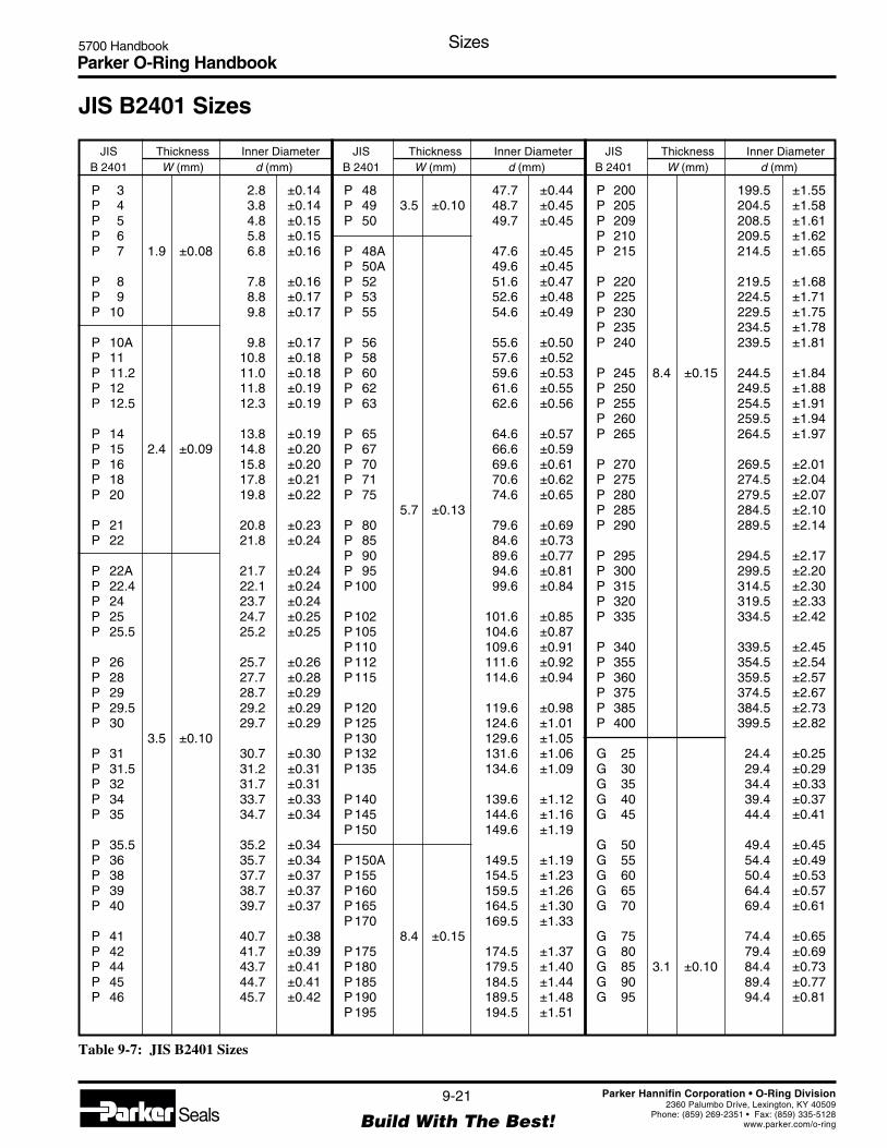
Parker O-Ring Handbook5700 Handbook Sizes
9-21
Build With The Best!SealsParker Hannifin Corporation • O-Ring Division
2360 Palumbo Drive, Lexington, KY 40509Phone: (859) 269-2351 • Fax: (859) 335-5128
www.parker.com/o-ring
P 3 2.8 ±0.14P 4 3.8 ±0.14P 5 4.8 ±0.15P 6 5.8 ±0.15P 7 1.9 ±0.08 6.8 ±0.16
P 8 7.8 ±0.16P 9 8.8 ±0.17P 10 9.8 ±0.17
P 10A 9.8 ±0.17P 11 10.8 ±0.18P 11.2 11.0 ±0.18P 12 11.8 ±0.19P 12.5 12.3 ±0.19
P 14 13.8 ±0.19P 15 2.4 ±0.09 14.8 ±0.20P 16 15.8 ±0.20P 18 17.8 ±0.21P 20 19.8 ±0.22
P 21 20.8 ±0.23P 22 21.8 ±0.24
P 22A 21.7 ±0.24P 22.4 22.1 ±0.24P 24 23.7 ±0.24P 25 24.7 ±0.25P 25.5 25.2 ±0.25
P 26 25.7 ±0.26P 28 27.7 ±0.28P 29 28.7 ±0.29P 29.5 29.2 ±0.29P 30 29.7 ±0.29
3.5 ±0.10P 31 30.7 ±0.30P 31.5 31.2 ±0.31P 32 31.7 ±0.31P 34 33.7 ±0.33P 35 34.7 ±0.34
P 35.5 35.2 ±0.34P 36 35.7 ±0.34P 38 37.7 ±0.37P 39 38.7 ±0.37P 40 39.7 ±0.37
P 41 40.7 ±0.38P 42 41.7 ±0.39P 44 43.7 ±0.41P 45 44.7 ±0.41P 46 45.7 ±0.42
JIS B2401 Sizes
JIS Thickness Inner DiameterB 2401 W (mm) d (mm)
P 48 47.7 ±0.44P 49 3.5 ±0.10 48.7 ±0.45P 50 49.7 ±0.45
P 48A 47.6 ±0.45P 50A 49.6 ±0.45P 52 51.6 ±0.47P 53 52.6 ±0.48P 55 54.6 ±0.49
P 56 55.6 ±0.50P 58 57.6 ±0.52P 60 59.6 ±0.53P 62 61.6 ±0.55P 63 62.6 ±0.56
P 65 64.6 ±0.57P 67 66.6 ±0.59P 70 69.6 ±0.61P 71 70.6 ±0.62P 75 74.6 ±0.65
5.7 ±0.13P 80 79.6 ±0.69P 85 84.6 ±0.73P 90 89.6 ±0.77P 95 94.6 ±0.81P 100 99.6 ±0.84
P 102 101.6 ±0.85P 105 104.6 ±0.87P 110 109.6 ±0.91P 112 111.6 ±0.92P 115 114.6 ±0.94
P 120 119.6 ±0.98P 125 124.6 ±1.01P 130 129.6 ±1.05P 132 131.6 ±1.06P 135 134.6 ±1.09
P 140 139.6 ±1.12P 145 144.6 ±1.16P 150 149.6 ±1.19
P 150A 149.5 ±1.19P 155 154.5 ±1.23P 160 159.5 ±1.26P 165 164.5 ±1.30P 170 169.5 ±1.33
8.4 ±0.15P 175 174.5 ±1.37P 180 179.5 ±1.40P 185 184.5 ±1.44P 190 189.5 ±1.48P 195 194.5 ±1.51
P 200 199.5 ±1.55P 205 204.5 ±1.58P 209 208.5 ±1.61P 210 209.5 ±1.62P 215 214.5 ±1.65
P 220 219.5 ±1.68P 225 224.5 ±1.71P 230 229.5 ±1.75P 235 234.5 ±1.78P 240 239.5 ±1.81
P 245 8.4 ±0.15 244.5 ±1.84P 250 249.5 ±1.88P 255 254.5 ±1.91P 260 259.5 ±1.94P 265 264.5 ±1.97
P 270 269.5 ±2.01P 275 274.5 ±2.04P 280 279.5 ±2.07P 285 284.5 ±2.10P 290 289.5 ±2.14
P 295 294.5 ±2.17P 300 299.5 ±2.20P 315 314.5 ±2.30P 320 319.5 ±2.33P 335 334.5 ±2.42
P 340 339.5 ±2.45P 355 354.5 ±2.54P 360 359.5 ±2.57P 375 374.5 ±2.67P 385 384.5 ±2.73P 400 399.5 ±2.82
G 25 24.4 ±0.25G 30 29.4 ±0.29G 35 34.4 ±0.33G 40 39.4 ±0.37G 45 44.4 ±0.41
G 50 49.4 ±0.45G 55 54.4 ±0.49G 60 50.4 ±0.53G 65 64.4 ±0.57G 70 69.4 ±0.61
G 75 74.4 ±0.65G 80 79.4 ±0.69G 85 3.1 ±0.10 84.4 ±0.73G 90 89.4 ±0.77G 95 94.4 ±0.81
JIS Thickness Inner DiameterB 2401 W (mm) d (mm)
JIS Thickness Inner DiameterB 2401 W (mm) d (mm)
Table 9-7: JIS B2401 Sizes

Parker O-Ring Handbook5700 Handbook Sizes
9-22
Build With The Best!SealsParker Hannifin Corporation • O-Ring Division
2360 Palumbo Drive, Lexington, KY 40509Phone: (859) 269-2351 • Fax: (859) 335-5128
www.parker.com/o-ring
Table 9-7: JIS B2401 Sizes
G 200 199.3 ±1.55G 205 204.3 ±1.58G 210 209.3 ±1.61G 215 214.3 ±1.64G 220 219.3 ±1.68
G 225 224.3 ±1.71G 230 229.3 ±1.73G 235 5.7 ±0.13 234.3 ±1.77G 240 239.3 ±1.81G 245 244.3 ±1.84
G 250 249.3 ±1.88G 255 254.3 ±1.91G 260 259.3 ±1.94G 265 264.3 ±1.97G 270 269.3 ±2.01
G 275 274.3 ±2.04G 280 279.3 ±2.07G 285 284.3 ±2.10G 290 289.3 ±2.14G 295 294.3 ±2.17
G 100 99.4 ±0.85G 105 104.4 ±0.87G 110 109.4 ±0.91G 115 114.4 ±0.94G 120 119.4 ±0.98
3.1 ±0.10G 125 124.4 ±1.01G 130 129.4 ±1.05G 135 134.4 ±1.08G 140 139.4 ±1.12G 145 144.4 ±1.16
G 150 149.3 ±1.19G 155 154.3 ±1.23G 160 159.3 ±1.26G 165 164.3 ±1.30G 170 169.3 ±1.33
G 175 174.3 ±1.37G 180 179.3 ±1.40G 185 5.7 ±0.13 184.3 ±1.44G 190 189.3 ±1.47G 195 194.3 ±1.51
Parker JIS B2401 Sizes (Continued)
G 300 299.3 ±2.20G 305 304.3 ±2.24G 310 309.3 ±2.27G 315 314.3 ±2.30G 320 319.3 ±2.33
G 325 324.3 ±2.36G 330 329.3 ±2.39G 335 5.7 ±0.13 334.3 ±2.42G 340 339.3 ±2.45G 345 344.3 ±2.48
G 350 349.3 ±2.51G 355 354.3 ±2.54G 360 359.3 ±2.57G 365 364.3 ±2.60G 370 369.3 ±2.63
G 375 374.3 ±2.67G 380 379.3 ±2.70G 385 384.3 ±2.73G 390 389.3 ±2.76G 395 394.3 ±2.79
G 400 399.3 ±2.82
JIS Thickness Inner DiameterB 2401 W (mm) d (mm)
JIS Thickness Inner DiameterB 2401 W (mm) d (mm)
JIS Thickness Inner DiameterB 2401 W (mm) d (mm)

Parker O-Ring Handbook5700 Handbook Appendix
10-1
Build With The Best!SealsParker Hannifin Corporation • O-Ring Division
2360 Palumbo Drive, Lexington, KY 40509Phone: (859) 269-2351 • Fax: (859) 335-5128
www.parker.com/o-ring
Section XAppendix
10.1 O-Ring Failure Modes ........................................................................................................................ 10-2
10.1.1 Why an O-Ring Fails Prematurely ............................................................................................ 10-2
10.1.1.1 Compression Set ................................................................................................................ 10-2
10.1.1.2 Extrusion and Nibbling ..................................................................................................... 10-2
10.1.1.3 Spiral Failure ..................................................................................................................... 10-3
10.1.1.4 Explosive Decompression ................................................................................................. 10-4
10.1.1.5 Abrasion ............................................................................................................................. 10-4
10.1.1.6 Installation Damage ........................................................................................................... 10-4
10.1.1.7 Other Causes of O-Ring Failure ........................................................................................ 10-4
10.1.2 Assembly Hints .......................................................................................................................... 10-5
10.1.2.1 Chamfers ........................................................................................................................... 10-5
10.1.2.2 Traversing of Cross Drilled Ports ...................................................................................... 10-6
10.1.2.3 Cleanliness and Cleaning Materials .................................................................................. 10-6
10.1.2.4 Stretching for Assembly .................................................................................................... 10-6
10.1.2.5 Rolling ............................................................................................................................... 10-7
10.1.2.6 Sharp Edges ....................................................................................................................... 10-7
10.1.3 Failure Mode and Effects Analysis for Customers .................................................................... 10-7
10.2 Glossary of Seal and Rubber Terms.................................................................................................... 10-9
10.3 Abbreviations .................................................................................................................................... 10-15
10.4 Standard Shrinkage ........................................................................................................................... 10-16
10.4.1 Procedure for O-Rings Molded of Compounds Having Non-Standard Shrinkage Rates ....... 10-16
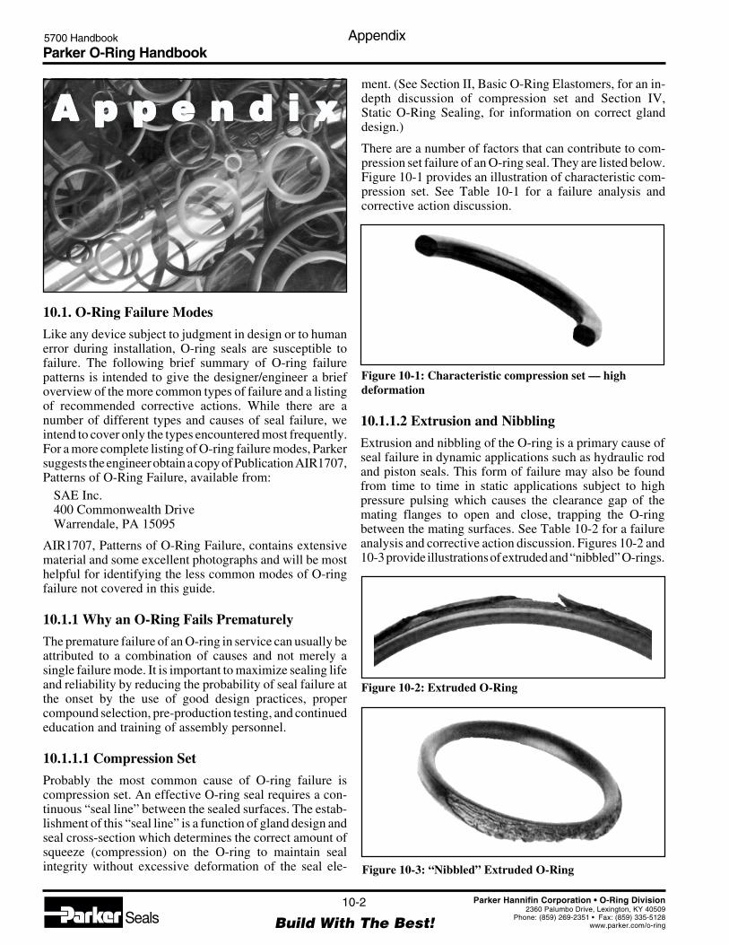
Parker O-Ring Handbook5700 Handbook Appendix
10-2
Build With The Best!SealsParker Hannifin Corporation • O-Ring Division
2360 Palumbo Drive, Lexington, KY 40509Phone: (859) 269-2351 • Fax: (859) 335-5128
www.parker.com/o-ring
10.1. O-Ring Failure Modes
Like any device subject to judgment in design or to humanerror during installation, O-ring seals are susceptible tofailure. The following brief summary of O-ring failurepatterns is intended to give the designer/engineer a briefoverview of the more common types of failure and a listingof recommended corrective actions. While there are anumber of different types and causes of seal failure, weintend to cover only the types encountered most frequently.For a more complete listing of O-ring failure modes, Parkersuggests the engineer obtain a copy of Publication AIR1707,Patterns of O-Ring Failure, available from:
SAE Inc.400 Commonwealth DriveWarrendale, PA 15095
AIR1707, Patterns of O-Ring Failure, contains extensivematerial and some excellent photographs and will be mosthelpful for identifying the less common modes of O-ringfailure not covered in this guide.
10.1.1 Why an O-Ring Fails Prematurely
The premature failure of an O-ring in service can usually beattributed to a combination of causes and not merely asingle failure mode. It is important to maximize sealing lifeand reliability by reducing the probability of seal failure atthe onset by the use of good design practices, propercompound selection, pre-production testing, and continuededucation and training of assembly personnel.
10.1.1.1 Compression Set
Probably the most common cause of O-ring failure iscompression set. An effective O-ring seal requires a con-tinuous “seal line” between the sealed surfaces. The estab-lishment of this “seal line” is a function of gland design andseal cross-section which determines the correct amount ofsqueeze (compression) on the O-ring to maintain sealintegrity without excessive deformation of the seal ele-
A p p e n d i xA p p e n d i xA p p e n d i xA p p e n d i xA p p e n d i xment. (See Section II, Basic O-Ring Elastomers, for an in-depth discussion of compression set and Section IV,Static O-Ring Sealing, for information on correct glanddesign.)
There are a number of factors that can contribute to com-pression set failure of an O-ring seal. They are listed below.Figure 10-1 provides an illustration of characteristic com-pression set. See Table 10-1 for a failure analysis andcorrective action discussion.
10.1.1.2 Extrusion and Nibbling
Extrusion and nibbling of the O-ring is a primary cause ofseal failure in dynamic applications such as hydraulic rodand piston seals. This form of failure may also be foundfrom time to time in static applications subject to highpressure pulsing which causes the clearance gap of themating flanges to open and close, trapping the O-ringbetween the mating surfaces. See Table 10-2 for a failureanalysis and corrective action discussion. Figures 10-2 and10-3 provide illustrations of extruded and “nibbled” O-rings.
Figure 10-1: Characteristic compression set — highdeformation
Figure 10-2: Extruded O-Ring
Figure 10-3: “Nibbled” Extruded O-Ring

Parker O-Ring Handbook5700 Handbook Appendix
10-3
Build With The Best!SealsParker Hannifin Corporation • O-Ring Division
2360 Palumbo Drive, Lexington, KY 40509Phone: (859) 269-2351 • Fax: (859) 335-5128
www.parker.com/o-ring
Extrusion and Nibbling
Failure Analysis
In general, extrusion and nibbling are caused by one ormore of the following conditions:
1. Excessive clearances.
2. High pressure (in excess of system design or highpressure excursions).
3. O-ring material too soft.
4. Degradation (swelling, softening, shrinking, crack-ing, etc.) of O-ring material by system fluid.
5. Irregular clearance gaps caused by eccentricity.
6. Increase in clearance gaps due to excessive systempressure.
7. Improper machining of O-ring gland (sharp edges).
8. Improper size (too large) O-ring installed causingexcessive filling of groove.
Prevention/Correction
Suggested solutions to the causes of Extrusion andNibbling listed above are:
1. Decrease clearance by reducing machining toler-ances.
2. Use back-up devices. (See Section VI, ParBackBack-Up Rings, for information on Parker Parbakanti-extrusion devices.)
3. Check O-ring material compatibility with systemfluid.
4. Increase rigidity of metal components.
5. Replace current O-ring with a harder O-ring.
6. Break sharp edges of gland to a minimum radius0.002 inches.
7. Insure installation of proper size O-rings.
8. Use alternative seal shape. for example, in somelong stroke piston or rod applications, the ParkerT-Seal, with its built-in back-up rings, may preventextrusion and spiral failure.
Identification of Extrusion Failure
A typical example of O-ring extrusion is when edges ofthe ring on the low pressure or downstream side of thegland exhibit a “chewed” or “chipped” appearance. Inan O-ring that has failed due to nibbling, it may havethe appearance that many small pieces have beenremoved from the low pressure side. In some forms ofextrusion, more than 50% of the O-ring may be de-stroyed before catastrophic leakage is observed.
Table 10-2: Extrusion and Nibbling Failure Analysis
Compression Set
Failure Analysis
In general, Compression Set is caused by one or moreof the following conditions:1. Selection of O-ring material with inherently poor
compression set properties.2. Improper gland design.3. Excessive temperature developed causing the O-
ring to harden and lose its elastic properties. (Hightemperatures may be caused by system fluids, exter-nal environmental factors, or frictional heat build-up.)
4. Volume swell of the O-ring due to system fluid.5. Excessive squeeze due to over tightening of adjust-
able glands.6. Incomplete curing (vulcanization) of O-ring mate-
rial during production.7. Introduction of fluid incompatible with O-ring ma-
terial.
Prevention/Correction
Suggested solutions to the causes of compression set are:1. Use “Low-Set” O-ring material whenever possible.2. Select O-ring material compatible with intended
service conditions.3. Reduce system operating temperature.4. Check frictional heat build-up at seal interface and
reduce if excessive.5. Inspect incoming O-ring shipments for correct physi-
cal properties. (Requesting the Parker C.B.I. num-ber will be of great assistance in this area. For acomplete discussion of this exclusive Parker ser-vice, look later in this section.)
Identification of Compression Set Failure
A typical example of classic O-ring compression set insimplistic terms: the O-ring ceases to be “O” shapedand is permanently deformed into a flat sided oval, theflat sides of which were the original seal interfaceunder compression before failure.
Table 10-1: Compression Set Failure Analysis
10.1.1.3 Spiral Failure
Spiral failure of an O-ring is often found on long strokehydraulic piston seals and to a lesser degree on rod seals.This type of O-ring failure is caused when the seal becomes“hung-up’’ at one point on its diameter (against the cylinderwall) and slides and rolls at the same time. The resultanttwisting of the O-ring as the sealed device is cycled finally

Parker O-Ring Handbook5700 Handbook Appendix
10-4
Build With The Best!SealsParker Hannifin Corporation • O-Ring Division
2360 Palumbo Drive, Lexington, KY 40509Phone: (859) 269-2351 • Fax: (859) 335-5128
www.parker.com/o-ring
10.1.1.6 Installation Damage
Many O-ring failures can be directly attributed to improperinstallation. In spite of its simple appearance, the O-ring isa precision device requiring care during installation. Someof the more frequent causes of O-ring failure due to carelesshandling are listed in Table 10-6.
10.1.1.7 Other Causes of O-Ring Failure
Damages to O-rings can be caused by compounding of thecauses described in paragraphs 10.1.2.1 through 10.1.2.6.Upon failure of an O-ring check all causes mentionedabove.
Spiral Failure
Failure Analysis
As stated above, spiral failure is generally caused by anO-ring both sliding and rolling at the same time.Conditions which may cause this to occur are:1. Eccentric components.2. Wide clearance combined with side loads.3. Uneven surface finishes.4. Inadequate or improper lubrication.5. O-ring too soft.6. Stroke speed (usually too slow).7. Improper installation (O-ring pinched or rolled).
Prevention/Correction
Suggested solutions to the causes of spiral failure areas follows:1. Improve surface finish of sealed assembly at dy-
namic interface (Cylinder Bore, Piston Rod).2. Check for out-of-round components (Cylinder Bores
especially).3. Provide proper lubrication. Consider the use of
internally lubed O-rings.4. Replace with a harder O-ring.5. Consider use of alternate seal shapes. for example,
the Parker T-seal is specifically designed to preventspiral failure and its use will allow for increasedtolerances because of built-in anti-extrusion back-up rings. Parker T-Seals are available to fit a num-ber of standard AS568A O-ring grooves and maydirectly interchange with O-rings in most cases.
Identification of Spiral Failure
You will see the typical cuts that gave this type ofO-ring failure its name.
Table 10-3: Spiral Failure Failure Analysis
causes the seal to develop a series of deep spiral cuts(usually at a 45° angle) on the surface of the seal. (For morecomplete discussion on spiral failure, see Section IV,Static O-Ring Sealing).
Table 10-3 provides a discussion of spiral failure analysis.Figure 10-4 illustrates spiral failures.
Figure 10-4: Twisted O-ring with spiral marking, or withspiral cuts in surface
10.1.1.4 Explosive Decompression
As system pressures increase we are seeing this type ofO-ring failure with more frequency. It might be termedO-ring embolism, in that after a period of service under highpressure gas, when the pressure is reduced too rapidly, thegas trapped within the internal structure of the O-ringexpands rapidly, causing small ruptures or embolisms onthe O-ring surface.
Table 10-4 provides a failure analysis discussion. Figure 10-5illustrates an O-ring damaged by explosive decompression.
10.1.1.5 Abrasion
Another rather common type of O-ring failure is abrasion.This usually is found only in dynamic seals subject either toreciprocating, oscillating, or rotary motion. Possible causesof O-ring abrasion are listed in Table 10-5. Figure 10-6shows wear on an O-ring.
Figure 10-5: O-Ring Damaged by ExplosiveDecompression

Parker O-Ring Handbook5700 Handbook Appendix
10-5
Build With The Best!SealsParker Hannifin Corporation • O-Ring Division
2360 Palumbo Drive, Lexington, KY 40509Phone: (859) 269-2351 • Fax: (859) 335-5128
www.parker.com/o-ring
Explosive Decompression
Failure Analysis
Explosive decompression or gas expansion rupture iscaused by high pressure gas trapped within the internalstructure of the elastomeric seal element. Rapid de-crease in system pressure causes the trapped gas toexpand to match the external pressure and this expan-sion causes blisters and ruptures on the seal surface. Ifthe volume of trapped gas is small, the blisters mayrecede as the pressure is equalized with little effect onseal integrity. Excessive trapped gas may cause totaldestruction of the seal. (Refer to Section III, O-RingApplications, for more information on this problem.)
Prevention/Correction
Suggested solutions to explosive decompression are:1. Increase decompression time to allow trapped gas
to work out of seal material.2. Choose a seal material with good resistance to
explosive decompression.3. If problem persists and pressures are very high,
consider use of Parker Metal Seals.
Identification of Explosive Decompression Failure
The seal subjected to explosive decompression willoften exhibit small pits or blisters on its surface. Insevere cases, examination of the internal structure ofthe O-ring will reveal other splits and fissures.
Table 10-4 Explosive Decompression Failure Analysis
Abrasion
Failure Analysis
In general, abrasion of O-ring seals is caused by one ormore of the following:1. Improper finish of the surface in dynamic contact
with the O-ring. This surface finish may be toorough, acting as an abrasive, or too smooth, causinginadequate lubrication due to inability of surface tohold lubricant.
2. Improper lubrication provided by system fluid.3. Excessive temperatures.4. Contamination of system fluid by abrasive particles.
Prevention/Correction
Suggested solutions to problems caused by abrasion are:1. Use proper surface finish (see surface finish in
Dynamic Seals section).2. Provide adequate lubrication by use of proper sys-
tem fluid.3. Consider use of internally lubricated O-rings to
reduce friction and wear.4. Check for contamination of fluid and eliminate
source. Install filters if necessary.5. Consider changing to an O-ring material with im-
proved abrasion resistance.
Table 10-5: Abrasion Failure Analysis
Figure 10-6: Wear is Seen as Flattening of O-ring on OneSide
Although not illustrated here, there are several other pos-sible causes of O-ring failure. They are:
1. Weather and ozone degradation2. Heat aging and oxidation3. Loss of plasticizer(s)
If you encounter an unusual type of O-ring failure or areunable to identify a particular failure mode, please feel freeto contact Parker Seal Group O-Ring Division Inside SalesEngineering Department for assistance. In most cases theseexperienced engineers will be able to offer both an identi-fication of the problem and a number of possible solutions.
10.1.2 Assembly Hints
Leak-free seals are achieved only when a proper sealingmaterial is selected in the right size and sufficiently de-formed. Correct deformation depends on observance ofmachine element tolerances and surface finishes. In practi-cal terms all factors influencing the seal must be consid-ered. Inadequate or improper assembly will lead to highservicing costs and subsequent downtime.
10.1.2.1 Chamfers
To prevent damaging of seals during assembly, chamfersare necessary on all leading edges. All edges must be freefrom burrs and sharp edges bevelled.
Figure 10-7 shows the leading edge chamfer and an O-ringbefore deformation. The dimension X should be greaterthan dimension Y to ensure a trouble-free assembly operation.

Parker O-Ring Handbook5700 Handbook Appendix
10-6
Build With The Best!SealsParker Hannifin Corporation • O-Ring Division
2360 Palumbo Drive, Lexington, KY 40509Phone: (859) 269-2351 • Fax: (859) 335-5128
www.parker.com/o-ring
Figure 10-7: Chamfers
Figure 10-8: Drilled Port Assembly
O-Ring Can Be ShearedZ
Internal Chamfer Optimal Solution
Assembly Example of Piston
15° to 20°
Assembly Example of Rod
15°to 20°
"Leading Edge Chamfer"X>Y
X
Y
15°to 20°
Installation Damage
Failure AnalysisDamage to an O-ring during installation can occur when:1. There are sharp corners on mating metal compo-
nents such as the O-ring gland or threads overwhich the O-ring must pass during assembly.
2. Insufficient lead-in chamfer.3. Blind grooves in multi-port valves.4. Oversize O-ring on piston seal application.5. Undersize O-ring on rod application.6. O-ring twisted/pinched during installation.7. O-ring not properly lubricated before installation.8. O-ring dirty upon installation.9. O-ring gland and/or other surfaces over which
O-ring must pass during assembly contaminatedwith metal particles.
10. General carelessness.
Prevention/CorrectionProbably the best way to prevent damage to O-ringsduring installation is the use of good old fashioned“Common Sense”. There are some specific solutionswhich are listed below:1. Break all sharp edges on metal components.2. Provide a 20° lead-in chamfer.3. Check all components for cleanliness before in-
stallation.4. Tape all threads over which the O-ring will pass.5. Use an O-ring lubricant such as Parker O-Lube or
Parker Super O-Lube if its use will not contami-nate system.
6. Double check O-ring to insure correct size andmaterial.
7. Be CAREFUL.
Table 10-6: Installation Damage Failure Analysis
10.1.2.2 Traversing of Cross-Drilled Ports
An O-ring can be sheared when a spool or rod moves in abore broken by cross-drilled ports. The deformed O-ringreturns to its original round cross-section as it enters theport and is sheared as it leaves the drilled area. To avoid this,connection holes should be repositioned. If repositioningshould not be possible, an internal chamfer is recom-mended.
Optimal solution is the relief of the bore on completecircumference which allows the O-ring to return to a roundcross-section before being compressed again. See Figure 10-8.
10.1.2.3 Cleanliness and Cleaning Materials
Lack of cleanliness of O-ring glands leads to leakage. Toensure protection from foreign particles of sealing facesduring working life it is necessary to use filters or to planmaintenance cycles.
Cleaning material must also be a medium which is compat-ible with the elastomer. Also grease used to ease assemblymust be compatible.
10.1.2.4 Stretching for Assembly
O-rings or back-up rings can be stretched during assemblyby 50% of their inner diameters. With small inner diametersthe percentage can be significantly greater eventuallybecoming critical.

Parker O-Ring Handbook5700 Handbook Appendix
10-7
Build With The Best!SealsParker Hannifin Corporation • O-Ring Division
2360 Palumbo Drive, Lexington, KY 40509Phone: (859) 269-2351 • Fax: (859) 335-5128
www.parker.com/o-ring
It therefore is important to ensure that the stretch remainsless than elongation at break given in compound datasheets. If an O-ring is stretched to near its elastic limit it willstill return to its original size after a short delay.
10.1.2.5 Rolling
O-rings of large inner diameters and small cross-sectionstend to roll during assembly. An O-ring rolled during fittingcan be prone to spiral failure (cf. paragraph 10.1.2.3) ortend to leak. See Figure 10-9.
10.1.2.6 Sharp Edges
O-rings should not be drawn during fitting over sharpedges, threads, slits, bores, glands, splines, etc. Such sharpedges must be removed or covered. Fitting aids assistassembly and thus avoid sharp edges. See Figures 10-10and 10-11.
10.1.3 Failure Mode and Effects Analysis forCustomers
Parker Seal has a wide network of people who are trainedto analyze your requirements and assist in suggestingintelligent solutions to specific problems during allstages…design…prototype…testing…qualification…specifi-cation writing…and purchasing. All these services can besupplied by a trained Parker Territory Sales Manager orParker Distributor.
Parker Territory Sales Managers serving customers in thefield are trained to recognize undesirable or uneconomicalproposed applications in favor of those that are logical and
cost efficient. You can count on your Parker Territory SalesManager and your Parker Distributor to give you goodcounsel. They can help you in many ways — preparation ofpreliminary sketches, submission of working samples fortest and evaluation, and even during qualification of acomponent or entire assembly.
Parker Seal also has the capability to analyze seals and theirbehavior in proposed applications through Finite ElementAnalysis (FEA). FEA is a powerful tool which allows thedesigner and the engineer to design complex parts and then
Figure 10-10: Use of a Fitting Aid
Use of a Fitting Aid
Figure 10-11: Use of a Stamp and a Location Aid
Stamp
Location Aid
Fitting Back-Stop
Use of a Stamp and a Location Aid
StampFitting Sleeve
Location Aid
Fitting Back-Stop
FluidPressure
Shaft Small Area
LargeArea
Figure 10-9: Rolling of O-ring
Action of Fluid Pressure to Prevent Rolling of O-ring
Ring Cross-Sections for Reciprocating Seals
O-Ring Square-Ring Delta-RingX-RingAll are subject to torsional or spiral failure.

Parker O-Ring Handbook5700 Handbook Appendix
10-8
Build With The Best!SealsParker Hannifin Corporation • O-Ring Division
2360 Palumbo Drive, Lexington, KY 40509Phone: (859) 269-2351 • Fax: (859) 335-5128
www.parker.com/o-ring
verify with FEA mathematical models whether the designwill perform under actual conditions. If the proposed de-sign shows shortcomings under this modeling analysis,changes can easily be made in the design until acceptableperformance is predicted by the model. All this can be donein a matter of days without investment in tooling, prototypeparts, or physical testing. Parker engineers are available tohelp you with your sealing questions and all are fully
qualified to recommend solutions to your sealing problemsand how these problems can be corrected to prevent futurefailure. At Parker Seal, customer satisfaction is our goal.Our internal and field personnel are ready to help you withall your sealing needs, and your Authorized Parker SealDistributor is a sealing expert who can assure you fastservice and the kind of reliable seals you need, when youneed them.
Parker O-Ring Handbook5700 Handbook Appendix
10-9
Build With The Best!SealsParker Hannifin Corporation • O-Ring Division
2360 Palumbo Drive, Lexington, KY 40509Phone: (859) 269-2351 • Fax: (859) 335-5128
www.parker.com/o-ring
10.2 Glossary of Seal and Rubber Terms
— A —Abrasion: The wearing away of a surface in service by
mechanical action such as rubbing, scraping or erosion.
Abrasion Resistance: The ability of a rubber compound toresist mechanical wear.
Absorption: The physical mechanism by which one sub-stance attracts and takes up another substance (liquid, gas,or vapor) into its INTERIOR.
Accelerated Life Test: Any set of test conditions designed toreproduce in a short time the deteriorating effect obtainedunder normal service conditions.
Accelerated Service Test: A service or bench test in whichsome service condition, such as speed, or temperature, orcontinuity of operation, is exaggerated in order to obtaina result in shorter time.
Accelerator: A substance which hastens the vulcanization ofan elastomer causing it to take place in a shorter time or ata lower temperature.
Acid Resistant: Withstands the action of acids.
Adhere: To cling or stick together.
Adhesion: Tendency of rubber to bond or cling to a contactsurface.
Adsorption: The physical mechanism by which one sub-stance attracts another substance (either solid, liquid, gas,or vapor) to its SURFACE and through molecular forcescauses the incident substance to adhere thereon.
After Cure: Continuation of vulcanization after the desiredcure is effected and the heat source removed.
Aging: To undergo changes in physical properties with age orlapse of time.
Aging, Oxygen Bomb: A means of accelerating the change inphysical properties of rubber compounds by exposingthem to the action of oxygen at an elevated temperatureand pressure.
Air Bomb: Similar to an oxygen bomb but used with air. Usedfor accelerated aging test.
Air Checks: Surface markings or depressions due to trappingair between the material being cured and the mold or presssurface.
Air Curing: The vulcanization of a rubber product in air asdistinguished from vulcanizing in a press or steam vulca-nizer.
Alpha (ααααα) Particles: Positively charged particles composedof two protons and neutrons (often referred to simply ashelium atom nuclei) and characterized by limited penetra-tion.
Ambient Temperature: The surrounding temperature rela-tive to a given point of application.Note: Ambient temperature is not necessarily the same asatmospheric temperature.
Aniline Point: The lowest temperature at which equal vol-umes of pure, fresh aniline and an oil will completelydissolve in one another is the aniline point of the oil.
Antioxidant: An organic substance which inhibits or retardsoxidation.
Antiozonant: A substance that retards or prevents the appear-ance of cracks from the action of ozone when the elas-tomer is exposed under tension, either statically or dy-namically, to air containing ozone.
Antirad: A material which inhibits radiation damage.
Atmospheric Cracking: Cracks produced in surface of rub-ber articles by exposure to atmospheric conditions.
— B —Backrind: Distortion at the parting line usually in the form of
a ragged indentation.
Back-Up Ring: (Anti-extrusion device) a ring of relativelyhard and tough material placed in the gland between theO-ring and groove side walls, to prevent extrusion of theO-ring.
Bake-Out: A process whereby a vacuum system is heated fora given time at some predetermined temperature to degasall the components, i.e. gages, fittings, valves, seals, etc.
Banbury Mixer: A specific type of internal mixer used toblend fillers and other ingredients with an elastomer.
Bench Test: A modified service test in which the serviceconditions are approximated, but the equipment is con-ventional laboratory equipment and not necessarily iden-tical with that in which the product will be employed.
Beta (βββββ) Particles: Negatively charged particles or electrons,characterized by limited penetration.
Bleeding: Migration to the surface of plasticizers, waxes, orsimilar materials to form a film or beads.
Blemish: A mark, deformity, or injury that impairs the appear-ance.
Blisters: A raised spot in the surface or a separation betweenlayers usually forming a void or air-filled space in thevulcanized article.
Bloom: A dusty or milky looking deposit that sometimesappears on the surface of an O-ring after molding andstorage, caused by migration of a liquid or solid to thesurface. Not to be confused with dust from externalsources.
Bond: The term commonly used to denote the attachment ofa given elastomer to some other member. Bonds may beclassified by type as follows:(a) Mechanical Bond — purely physical attachment ac-
complished by such means as “through” holes inter-locking fingers, envelope design, riveting etc.
(b) “Cold” Bond — adhesion of previously vulcanizedelastomer to another member through use of suitablecontact cements.
(c) “Vulcanized” Bond — adhesion of an elastomer to apreviously primed surface using heat and pressurethus vulcanizing the elastomer at the same time.
Parker O-Ring Handbook5700 Handbook Appendix
10-10
Build With The Best!SealsParker Hannifin Corporation • O-Ring Division
2360 Palumbo Drive, Lexington, KY 40509Phone: (859) 269-2351 • Fax: (859) 335-5128
www.parker.com/o-ring
Break: A separation or discontinuity in any part of an article.
Break-Out: Force to inaugurate sliding. Expressed in sameterms as friction. An excessive break-out value is taken asan indication of the development of adhesion.
Brittleness: Tendency to crack when deformed.
Buna-N: Same as nitrile rubber.
Buna-S: A general term for the copolymers of butadiene andstyrene. Also known as SBR and GRS.
Butt Joint: Joining two ends of a seal whereby the junction isperpendicular to the mold parting line.
Butyl: A copolymer of isobutylene with small amounts ofisoprene.
— C — Calender: A machine used to form sheets of rubber between
steel rollers.
Coefficient of Thermal Expansion: Average expansion perdegree over a stated temperature range expressed as afraction of initial dimension. May be linear or volumetric.
Cold Flexibility: Flexibility following exposure to a pre-determined low temperature for a predetermined time.
Cold Flow: Continued deformation under stress.
Cold Resistant: Able to withstand the effects of cold or lowtemperatures without loss of serviceability.
Commercially Smooth: Degree of smoothness of the surfaceof an article that is acceptable for use.
Compound: A term applied to a mixture of polymers andother ingredients, to produce a usable rubber material.
Compression Modulus: The ratio of the compressive stressto the resulting compressive strain (the latter expressed asa fraction of the original height or thickness in the direc-tion of the force). Compression modulus may be eitherstatic or dynamic.
Compression Set: The amount by which a rubber specimenfails to return to original shape after release of compres-sive load.
Conductive Rubber: A rubber capable of conducting elec-tricity. Most generally applied to rubber products used toconduct static electricity.
Copolymer: A polymer consisting of two different monomerschemically combined.
Corrosion (Packing): Corrosion of rigid member (usuallymetal) where it contacts packing. The actual corrodingagent is fluid medium trapped in the interface.
Corrosive (Packing): A property of packing whereby it isassumed often incorrectly, to promote corrosion of therigid member by the trapped fluid.
Cracking: A sharp break or fissure in the surface. Generallydue to excessive strain.
Creep: The progressive relaxation of a given rubber materialwhile it is under stress. This relaxation eventually resultsin permanent deformation or “set.”
Cross-Section: A seal as viewed if cut at right angles to themold parting line showing internal structure.
Cure: See Vulcanization.
Cure Date: Date when O-ring was molded; i.e., 2Q94 meanssecond quarter 1994.
Curing Temperature: The temperature at which the rubberproduct is vulcanized.
Cylinder: Chamber in which piston, plunger, ram, rod, orshaft is driven by or against the system fluid.
— D —Degassing: The intentional but controlled OUTGASSING
of a rubber substance or other material.
Diffusion: The mixing of two or more substances (solids,liquids, gases, or combinations thereof) due to the inter-mingling motion of their individual molecules. Gasesdiffuse more readily than liquids; similarly, liquids dif-fuse more readily than solids.
Durometer: (a) An instrument for measuring the hardness ofrubber. Measures the resistance to the penetration of anindentor point into the surface of rubber.
(b) Numerical scale of rubber hardness.
Dynamic: An application in which the seal is subject tomovement, or moving parts contact the seal.
Dynamic Packing: A packing employed in a joint whosemembers are in relative motion.
Dynamic Seal: A seal required to prevent leakage past partswhich are in relative motion.
— E —Elasticity: The property of an article which tends to return it
to its original shape after deformation.
Elastomer: Any synthetic or natural material with resilienceor memory sufficient to return to its original shape aftermajor or minor distortion.
Electron Volt: Unit of energy in atom calculations equal to1.602 E -12 ergs.
Elongation: Generally means “ultimate elongation” or per-cent increase in original length of a specimen when itbreaks.
ERG: Unit of energy (C.G.S.) equal to one dyne centimeter orapproximately equal to the work done by a force of 1 gramcausing a movement of 1 centimeter.
Evaporation: The direct conversion from liquid state to vaporstate of a given fluid.
Explosive Decompression: Rupturing of the substructurecaused by the rapid removal of pressure from an elastomercontaining dissolved gases. The result is a blistering orswelling of the material. Some elastomeric compounds arequite resistant to explosive decompression.
Extrusion: Distortion or flow, under pressure, of portion ofseal into clearance between mating metal parts.

Parker O-Ring Handbook5700 Handbook Appendix
10-11
Build With The Best!SealsParker Hannifin Corporation • O-Ring Division
2360 Palumbo Drive, Lexington, KY 40509Phone: (859) 269-2351 • Fax: (859) 335-5128
www.parker.com/o-ring
— F —Face Seal: A seal between two flat surfaces.
Filler: Chemically inert, finely divided material added to theelastomer to aid in processing and improve physicalproperties, i.e., abrasion resistance and strength — givingit varying degrees of hardness.
Flash: Excess rubber left around rubber part after molding dueto space between mating mold surfaces; removed bytrimming.
Flex Cracking: A surface cracking induced by repeatedbending or flexing.
Flex Resistance: The relative ability of a rubber article towithstand dynamic bending stresses.
Flock: Fibrous filler sometimes used in rubber compounding.
Flow Cracks: Surface imperfections due to improper flowand failure of stock to knit or blend with itself during themolding operation.
Fluid: A liquid or a gas.
Friction: Resistance to motion due to the contact of surfaces.
Friction (Breakout): Friction developed during initial orstarting motion.
Friction (Running): Constant friction developed during op-eration of a dynamic O-ring.
Fuel (Aromatic): Fuel which contains benzene or aromatichydrocarbons. Causes high swell of rubber.
Fuel (Nonaromatic): Fuel which is composed of straightchain hydrocarbons. Causes little swell of rubber.
— G —Gamma (γγγγγ) Radiation: Electromagnetic disturbance (pho-
tons) emanating from an atom nucleus. This type ofradiation travels in wave form much like X-rays or light,but has a shorter wave length (approx. 1 A° or 10 E -07mm). It is very penetrating.
Gasket: A device used to retain fluids under pressure or sealout foreign matter. Normally refers to a static seal.
Gland: Cavity into which O-ring is installed. Includes thegroove and mating surface of second part which togetherconfine the O-ring.
— H —Hardness: Resistance to a distorting force. Measured by the
relative resistance of the material to an indentor point ofany one of a number of standard hardness testing in-struments.
Hardness Shore A: The rubber durometer hardness as mea-sured on a Shore “A” gauge. Higher numbers indicateharder material. 35 Shore “A” durometer reading is con-sidered soft. 90 is considered hard.
Hermetic Seal: An airtight seal evidencing no detectableleakage.
Homogeneous: (a) General - a material of uniform composi-tion throughout. (b) In seals - a rubber seal without fabricor metal reinforcement.
Hypalon: DuPont trade name for chlorosulphonated poly-ethylene, an elastomer.
— I —Identification: Colored dots or stripes on seals for iden-
tification purposes. Seldom used today.
Immediate Set: The deformation found by measurementimmediately after removal of the load causing the defor-mation.
Immersion: Placing an article into a fluid, generally so it iscompletely covered.
Impact: The single, instantaneous stroke or contact of amoving body with another, either moving or at rest, suchas a large lump of material dropping on a conveyor belt.
— L —Leakage Rate: The rate at which a fluid (either gas or liquid)
passes a barrier. Total Leakage Rate includes the amountsthat diffuse or permeate through the material of the barrieras well as the amount that escapes around it.
Life Test: A laboratory procedure used to determine theamount and duration of resistance of an article to a specificset of destructive forces or conditions.
Linear Expansion: Expansion in any one linear dimension orthe average of all linear dimensions.
Logy: Sluggish, low snap or recovery of a material.
Low Temperature Flexibility: The ability of a rubber prod-uct to be flexed, bent or bowed at low temperatureswithout cracking.
— M —mm Hg: Millimeters of mercury. In vacuum work, this is a
measure of absolute pressure, being the height of a columnof mercury that the air or other gas will support. Standardatmospheric pressure will support a mercury column 760millimeters high (760 mm Hg.) Any value less than thisrepresents some degree of vacuum.
Memory: Tendency of a material to return to original shapeafter deformation.
Mirror Finish: A bright, polished surface.
Mismatch: Unsymmetrical seal caused by dissimilar cavitiesin mating mold sections.
Modulus: Tensile stress at a specified elongation. (Usually100% elongation for elastomers).
Modulus of Elasticity: One of the several measurements ofstiffness or resistance to deformation, but often incor-rectly used to indicate specifically static tension modulus.
Mold Cavity: Hollow space or cavity in the mold which isused to impart the desired form to the product beingmolded .

Parker O-Ring Handbook5700 Handbook Appendix
10-12
Build With The Best!SealsParker Hannifin Corporation • O-Ring Division
2360 Palumbo Drive, Lexington, KY 40509Phone: (859) 269-2351 • Fax: (859) 335-5128
www.parker.com/o-ring
Mold Finish: The uninterrupted surface produced by intimatecontact of rubber with the surface of the mold at vulcani-zation.
Mold Lubricant: A material usually sprayed onto the moldcavity surface prior to the introduction of the uncuredrubber, to facilitate the easy removal of the molded rubberparts.
Mold Marks: Indentations or ridges embossed into the skin ofthe molded product by irregularities in the mold cavitysurface.
Mold Register: Accuracy of alignment or fit of mold sections.
Mooney Scorch: The measurement of the rate at which arubber compound will cure or set up by means of theMooney Viscometer test instrument.
Mooney Viscosity: The measurement of the plasticity orviscosity of an uncompounded or compounded,unvulcanized, elastomeric seal material by means of theMooney Shearing Disk Viscometer.
— N —Nitrile: (Buna-N) The most commonly used elastomer for
O-rings because of its resistance to petroleum fluids, goodphysical properties and useful temperature range.
Nominal Dimension: Nearest fractional equivalent to actualdecimal dimension.
Non-Blooming: The absence of bloom.
— O —Occlusion: (a) The mechanical process by which vapors,
gases, liquids, or solids are entrapped within the folds ofa given substance during working or solidification.
(b) The materials so trapped.
Off-Register: Misalignment of mold halves causing out-of-round O-ring cross section.
Oil Resistant: Ability of a vulcanized rubber to resist theswelling and deteriorating effects of various type oils.
Oil Swell: The change in volume of a rubber article due toabsorption of oil or other or other fluid.
O-Ring: A torus; a circle of material with round cross sectionwhich effects a seal through squeeze and pressure.
O-Ring Seal: The combination of a gland and an O-ringproviding a fluid-tight closure. (Some designs may permitmomentary or minimum leakage.)
Moving (dynamic) — O-ring seal in which there is relativemotion between some gland parts and the O-ring — oscil-lating, reciprocating, or rotary motion.Non-moving (static) — O-ring seal in which there is norelative motion between any part of the gland and the O-ring (distortion from fluid pressure or swell from fluidimmersion is excluded).
Optimum Cure: State of vulcanization at which the mostdesirable combination of properties is attained.
Outgassing: A vacuum phenomenon wherein a substancespontaneously releases volatile constituents in the form ofvapors or gases. In rubber compounds, these constituentsmay include water vapor, plasticizers, air, inhibitors, etc.
Over Cure: A degree of cure greater than the optimumcausing some desirable properties to be degraded.
Oxidation: The reaction of oxygen on a compound usualdetected by a change in the appearance or feel of thesurface, or by a change in physical properties or both.
Oxygen Bomb: A chamber capable of holding oxygen at anelevated pressure which can be heated to an elevatedtemperature. Used for an accelerated aging test.
Ozone Resistance: Ability to withstand the deterioratingeffect of ozone (which generally causes cracking).
— P —Packing: A flexible device used to retain fluids under pressure
or seal out foreign matter. Normally refers to a dynamicseal.
Permanent Set: The deformation remaining after a specimenhas been stressed in tension for a definite period andreleased for a definite period.
Permeability: The rate at which a liquid or gas under pressurepasses through a solid material by diffusion and solution.In rubber terminology, it is the rate of gas flow expressedin atmospheric cubic centimeters per second through anelastomeric material one centimeter square and one cen-timeter thick (atm cc/cm²/cm sec).
Pit or Pock Mark: A circular depression, usually small.
Plasticizer: A substance, usually a viscous liquid, added to anelastomer to decrease stiffness, improve low temperatureproperties, and improve processing.
Plastometer: An instrument for measuring the plasticity ofraw or unvulcanized compounded rubber.
Pock Mark: See “Pit or Pock Mark”.
Polymer: A material formed by the joining together of many(poly) individual units (mer) of one or more monomers;synonymous with elastomer.
Porosity: Quality or state of being porous.
Post Cure: The second step in the vulcanization process forthe more exotic elastomers. Provides stabilization of partsand drives off decomposition products resulting from thevulcanization process.
— R —Radiation: An emission of varying energy content from a
disturbed atom undergoing internal change. There are twobroad classifications or types:(a) Corpuscular, comprising streams of particles either
neutral or charged, e.g. protons, electrons, neutrons.(b) Electromagnetic, comprising wave-like emissions
as gamma, ultraviolet, etc.
Parker O-Ring Handbook5700 Handbook Appendix
10-13
Build With The Best!SealsParker Hannifin Corporation • O-Ring Division
2360 Palumbo Drive, Lexington, KY 40509Phone: (859) 269-2351 • Fax: (859) 335-5128
www.parker.com/o-ring
Radiation Damage: A measure of the loss in certain physicalproperties of organic substances such as elastomers, dueprincipally to ionization of the long chain molecule. It isbelieved that this ionization process (i e. electron loss)results in redundant cross-linking and possible scission ofthe molecule. This effect is cumulative.
Radiation Dosage: The total amount of radiation energyabsorbed by a substance. This value is usually expressedin ergs per gram, and is denoted by the following units:(a) Roentgen - a quantity of gamma or X-ray radiation
equal to approximately 83 ergs of absorbed energyper gram of air.
(b) REP (Roentgen equivalent-physical) - a quantity ofionizing radiation that causes an energy absorption ofapproximately 83 to 93 ergs per gram of tissue.
(c) REM (Roentgen equivalent-man)—similar to REPexcept used to denote biological effects.
(d) RAD - the unit of dosage related to elastomers. It isindependent of type of radiation or specimen, anddenotes an energy absorption level of 100 ergs pergram (of elastomer). The RAD is approximatelyequal to 1.2 Roentgens.
Register, Off or Uneven: See Off-register.
Reinforcing Agent: Material dispersed in an elastomer toimprove compression, shear or other stress properties.
Relative Humidity: The ratio of the quantity of water vaporactually present in the atmosphere to the greatest amountpossible at the given temperature.
Resilient: Capable of returning to original size and shape afterdeformation.
Roentgen: See Radiation Dosage.
Rough Trim: Removal of superfluous material by pulling orpicking. Usually the removal of a small portion of the flashor sprue which remains attached to the product.
Rubber: Same as elastomer.
Rubber, Natural: Raw or crude rubber obtained from plantsources.
Rubber, Synthetic: Manufactured or man-made elastomers.
Runout (Shaft): Same as gyration; when expressed in inchesalone or accompanied by abbreviation “T.I.R.” (totalindicator reading), it refers to twice the radial distancebetween shaft axis and axis of rotation.
— S —Scorching: Premature curing or setting up of raw compound
during processing.
Seal: Any device used to prevent the passage of a fluid (gas orliquid).
Service: Operating conditions to be met.
Shaft: Reciprocating or rotating member usually within cyl-inder; not in contact with walls.
Shelf-Aging: The change in a material’s properties whichoccurs in storage with time.
Shore A Hardness: See Hardness and Durometer.
Shrinkage: Decreased volume of seal, usually caused byextraction of soluble constituents by fluids followed by airdrying.
Silicone Rubber: Elastomer that retains good propertiesthrough extra wide temperature range.
Size, Actual: Actual dimensions of the O-ring or other seal,including tolerance limits.
Size, Nominal: Approximate size of part in fractional di-mensions. May also indicate the actual size of the grooveinto which a nominal size seal fits.
Size Number: Number assigned to indicate inside and crosssection diameters of an O-ring. Sizes established in SAEstandard AS 568A have been adopted by the military andindustry.
Sorption: The term used to denote the combination of absorp-tion and adsorption processes in the same substance.
Specific Gravity: The ratio of the weight of a given substanceto the weight of an equal volume of water at a specifiedtemperature.
Sprue Marks: Marks left on the surface of a rubber part,usually elevated, after removal of the sprue or curedcompound in the gate through which the compound isinjected or transfer molded.
Squeeze: Cross section diametral compression of O-ringbetween surface of the groove bottom and surface of othermating metal part in the gland assembly.
Static Seal: Part designed to seal between parts having norelative motion. See Gasket.
Strain: Deflection due to a force.
Stress: Force per unit of original cross section area.
Sublimation: The direct conversion of a substance from solidstate to vapor state without passing through a transitoryliquid state. The vapor, upon recondensing, reforms intothe solid state with no intervening liquid phase.
Sun Checking: Surface cracks, checks or crazing caused byexposure to direct or indirect sunlight.
Swell: Increased volume of a specimen caused by immersionin a fluid (usually a liquid).
— T —Tear Resistance: Resistance to growth of a cut or nick when
tension is applied to the cut specimen Commonly ex-pressed as pounds per inch thickness.
Temperature Range: Maximum and minimum temperaturelimits within which a seal compound will function in agiven application.
Tensile Strength: Force in pounds per square inch required tocause the rupture of a specimen of a rubber material.
Terpolymer: A polymer consisting of three different mon-omers chemically combined.
Thermal Expansion: Expansion caused by increase in tem-perature. May be linear or volumetric.
Parker O-Ring Handbook5700 Handbook Appendix
10-14
Build With The Best!SealsParker Hannifin Corporation • O-Ring Division
2360 Palumbo Drive, Lexington, KY 40509Phone: (859) 269-2351 • Fax: (859) 335-5128
www.parker.com/o-ring
Threshold: The maximum tolerance of an elastomer to radia-tion dosage expressed as a total number of ergs per gram(or rads) beyond which the physical properties are signifi-cantly degraded. This is generally an arbitrary value,depending on function and environment.
Torque: The turning force of a shaft.
Torr: The unit of pressure used in vacuum measurement. It isequal to 1/760 of a standard atmosphere, and for allpractical purposes is equivalent to one millimeter ofmercury (mm Hg).
Example:25 mm Hg = 25 torr1 x 10-3 mm Hg = 10-3torr (millitorr)1 X 10⁻⁶ mm Hg = 10-6torr (microtorr)
Torsional Strength: Ability of rubber to withstand twisting.
TR-10: (10% Temperature retraction) A measure of the lowtemperature capability of an elastomer, being the tem-perature at which a stretched and frozen specimen hasretracted by 10% of the stretched amount. (ASTM methodD1329)
Trapped Air: Air which is trapped in a product or a moldduring cure. Usually causes a loose ply or cover, or asurface mark, depression or void.
Trim: The process involving removal of mold flash.
Trim Cut: Damage to mold skin or finish by too closetrimming.
— U —Under-Cure: Degree of cure less than optimum. May be
evidenced by tackiness, loginess, or inferior physicalproperties.
Ultimate Elongation: See Elongation.
— V —Vacuum: The term denoting a given space that is occupied by
a gas at less than atmospheric pressure. For degrees ofvacuum; see vacuum level.
Vacuum Level: The term used to denote the degree of vacuumevidenced by its pressure in torr (or mm Hg).(a) Rough vacuum — 760 torr to 1 torr(b) Medium vacuum — 1 torr to 10-3 torr(c) High vacuum — 10-3 torr to 10-6 torr(d) Very high (hard) vacuum — 10-6 torr to 10-9 torr(e) Ultra high (ultra hard) vacuum — Below 10-9 torr
Vapor: The gaseous state of a fluid that normally exists as aliquid under atmospheric conditions, i.e. a gas whosetemperature is below its critical temperature.
Vapor Pressure: The maximum pressure exerted by a liquid(or solid) heated to a given temperature in a closedcontainer.
Virtual Leak: An “apparent” leak in a vacuum system that istraceable, in fact, to some internal (and often accidental)release of occluded and/or sorbed gases. Example:
An undetected blister in a fused joint may eventually breakdown in a vacuum and suddenly (or slowly) release itsentrapped air, thereby indicating a “leak.”
Viscosity: The property of fluids and plastic solids by whichthey resist an instantaneous change of shape, i.e., resis-tance to flow.
Void: The absence of material or an area devoid of materialswhere not intended.
Volatilization: The transition of either a liquid or a soliddirectly into the vapor state. In the case of a liquid, thistransition is called evaporation, whereas in the case of asolid, it is termed sublimation.
Volume Change: A change in the volume of a seal as a resultof immersion in a fluid expressed as a percentage of theoriginal volume.
Volume Swell: Increase in physical size caused by the swell-ing action of a liquid.
Vulcanization: A thermo-setting reaction involving the use ofheat and pressure, resulting in greatly increased strengthand elasticity of rubber-like materials.
Vulcanizing Agent: A material which produces vulcani-zation of an elastomer.
— W —Width: Seal cross section or thickness.
Wiper Ring: A ring employed to remove excess fluid, mud,etc., from a reciprocating member before it reaches thepackings.

Parker O-Ring Handbook5700 Handbook Appendix
10-15
Build With The Best!SealsParker Hannifin Corporation • O-Ring Division
2360 Palumbo Drive, Lexington, KY 40509Phone: (859) 269-2351 • Fax: (859) 335-5128
www.parker.com/o-ring
10.3 AbbreviationsIR Isoprene RubberJAN Joint Army-NavyJIC Joint Industry Conference on Hydraulic Stan-
dards for Industrial EquipmentK Degrees Kelvin (Absolute) — (°C +273)Max MaximumMIL Military SpecificationMin MinimumMS Military StandardMVQ Silicone RubberNAS National Aerospace Standard (also National
Aircraft Standards [older meaning])NASA National Aeronautics and Space
AdministrationNBR Nitrile or Buna-N RubberNo NumberNR Natural RubberOD Outside Diameterpsi Pounds per square inchPVMQ Phenyl Silicone RubberQPL Military Qualified Products ListR or °R Degrees Rankine (Absolute) — (°F +460)Rad RadiusRMA Rubber Manufacturers AssociationRMS Root-Mean-Square; average value of surface
roughness measured in microinchesrpm Revolutions per minuteSAE Society of Automotive Engineers, Inc.SBR Styrene Butadiene Rubbersfm Surface Feet per minuteSpec SpecificationT Polysulfide RubberTemp. TemperatureUSAF United States Air ForceVMQ Silicone RubberW Width (seal cross section)WPAFB Wright-Patterson Air Force BaseXNBR Carboxylated Nitrile Rubber
ACM Polyacrylate RubberAF Air ForceAFML Air Force Material LaboratoryAMS Aerospace Material SpecificationAN (1) Army-Navy; (2) Air Force-NavyANA Air Force-Navy Aeronautical BulletinAND Air Force-Navy DesignAQL Acceptable Quality LevelARP Aerospace Recommended PracticeAS Aerospace StandardASTM American Society for Testing and Materialsatm Atmosphere (atmospheric)AU Polyurethane RubberBR Butadiene RubberC or °C Degrees Centigradecc Cubic centimeterC.G.S. Centimeter-Gram-Second; system of units for
length, mass, and timeCO Epichlorohydrin Rubbercpm Cycles per minuteCR Chloroprene (Neoprene)cs Cross SectionCSM Hypalon RubberDia DiameterECO Epichlorohydrin RubberEP, EPM Ethylene-Propylene RubberEPDM Ethylene-Propylene RubberEU Polyurethane RubberF or °F Degrees FahrenheitFED Federal SpecificationFKM (also FPM) Fluorocarbon RubberF.P.S. Foot-Pound-Second; system of units for length,
weight and timeFVMQ Fluorosilicone RubberGRS “Government Rubber Styrene”; now SBRID Inside DiameterIIR Butyl Rubberin. Inch

Parker O-Ring Handbook5700 Handbook Appendix
10-16
Build With The Best!SealsParker Hannifin Corporation • O-Ring Division
2360 Palumbo Drive, Lexington, KY 40509Phone: (859) 269-2351 • Fax: (859) 335-5128
www.parker.com/o-ring
10.4 Standard Shrinkage
“Standard” shrinkage is called “AN” shrinkage. Com-pounds that are manufactured from unusual formulationsor polymers will have different shrinkage rates associatedwith them. Some materials shrink LESS than the standard(AN) nitrile would in the same mold. These materials havebeen given an arbitrary CLASS(-1) shrinkage designation.Still other materials have shrinkage rates that are greaterthan the standard (AN) shrink rate. These progressivelylarger shrinkage rates have been arbitrarily called CLASSI through CLASS VII.
Table 10-7 lists the shrinkage class for some of our morepopular compounds. Table 10-8 lists all the possibilities fordimensions for Parker’s 2-xxx and 3-xxx series O-ringsizes depending upon the shrinkage of the material that ischosen.
In applications that require materials with shrinkage moreor less than the standard (AN) rate, the O-ring glanddimensions may have to be modified to provide the desiredsqueeze. If the assembled inside diameter of the O-ring isfixed, a high-shrink compound will be stretched more thana standard material, and this will reduce the O-ring cross-section further. See Figure 3-3 to observe the effect of thisstretch on the “W” Dimension. When O-rings of a high-shrink compound are required for use in standard (AN) orspecial dimensions, molds can be made to compensate forthe shrinkage, but at special mold costs.
It should be noted that many factors affect the shrinkage ofrubber compounds, including method (injection, compres-sion, transfer), time, temperature, and/or pressure, to namea few. As new manufacturing techniques for O-rings aredeveloped, there will be the possibility that shrinkage ratesof our compounds will change (or shift) correspondingly.For this reason, consultation with the factory is imperativeprior to specifying a particular Parker compound.
10.4.1 Procedure for O-Rings Molded ofCompounds Having Non-Standard ShrinkageRates
Determine the Finished Dimension andTolerances as Follows:
2- and 3- Sizes1. Locate the compound in Table 10-7 and note the shrink-
age class listed.2. Use this shrinkage class and the O-ring size number to
find the dimensions and tolerances in Table 10-8.Example: O-ring size 2-150, Compound S0355-75(1) Shrinkage Class IV (Table 10-7)(2) Dimensions and Tolerances2.816" ± .032" I.D. X .101" ±.004 W. (Table 10-8)
5- Sizes1. Locate the compound in Table 10-7, and note the shrink-
age class listed.2. Find the standard AN dimensions and tolerances in
Table 9-3. (If the I.D. is not known, refer to Table 9-4first.)
3. Find the actual I.D. and cross-section by multiplying thestandard I.D. and W. dimensions by the dimensionfactor from Table 10-10.
4. Find the I.D. tolerance by multiplying the standard I.D.by the tolerance factor from Table 10-10 and adding theresult to the standard tolerance.
5. Find the actual cross-section tolerance in Table 10-9.Example: O-ring Size 5-547, Compound S0355-75(1) Shrinkage Class III (Table 10-7)(2) Standard I.D. = 21.564 ± .100 W. = .139 ± .004(3) Actual I.D. = 21.564 X .984 = 21.219 Actual W. = .139 X .984 = .137(4) I.D. Tolerance = 21.564 X .0036 + .100 = ± .178(5) W. Tolerance ± .005
Actual Dimensions and Tolerance =21.219" ± .178" I.D. X .137" ± .005" W.
Note: Follow the procedure given for the 5-series to finddimensions and tolerances for special sizes for whichstandard shrinkage tooling exists.

Parker O-Ring Handbook5700 Handbook Appendix
10-17
Build With The Best!SealsParker Hannifin Corporation • O-Ring Division
2360 Palumbo Drive, Lexington, KY 40509Phone: (859) 269-2351 • Fax: (859) 335-5128
www.parker.com/o-ring
* Fluorocarbon compounds that have CLASS III shrinkage are manufactured using special compensated molds that will give nominaldimensions equivalent to the corresponding standard AN size. However, the tolerance spread will be that of a CLASS III shrinkagematerial unless otherwise specified.
** Run on Compensated Tooling.Note: The O-Ring Division is constantly developing new materials to solve customer needs. For the most up-to-date information, contact
the O-Ring Division directly.
Table 10-7: Compound Shrinkage Class
Compound ShrinkageNumber Class
47-071 ANN0103-70 ANG0244-70 ANC0267-50 ANN0287-70 AN
N0299-50 IN0304-75 ANS0317-60 IS0355-75 IVC0356-45 I
S0383-70 IIN0406-60 ANS0455-70 VS0469-40 ANV0494-70* II
N0497-70 -1N0506-65 ANN0507-90 -1N0508-75 -1E0515-80 AN
C0518-60 ANN0525-60 AN
E0540-80 ANN0545-40 IN0552-90 -1C0557-70 ANS0595-50 II
N0602-70 ANE0603-70 ANS0604-70 IA0607-70 IB0612-70 I
S0613-60 ANS0614-80 ANP0642-70 2E0652-90 -1E0667-70 I
N0674-70 ANV0680-70* IIE0692-75 ANV0709-90* IIIE0740-75 AN
N0741-75 ANV0747-75* III
E0798-70 IE0803-70 ANC0873-70 ANV0884-75* IIIE0893-80 AN
V0894-90* IIC0944-70 -1N0951-75 ANE0962-90 3E1028-70 AN
N1090-85 IA1107-70 IA1111-70 II
L1120-70** IVC1124-70 AN
L1223-60 IL1218-80 IL1186-80 IV1164-75* IIIV1226-75* III
Compound ShrinkageNumber Class
Compound ShrinkageNumber Class
Compound Shrinkage Class

Parker O-Ring Handbook5700 Handbook Appendix
10-18
Build With The Best!SealsParker Hannifin Corporation • O-Ring Division
2360 Palumbo Drive, Lexington, KY 40509Phone: (859) 269-2351 • Fax: (859) 335-5128
www.parker.com/o-ring
2-001 .029 .004 .040 .003 .029 .004 .040 .003 .029 .004 .040 .004 .029 .004 .040 .0042-002 .042 .004 .050 .042 .004 .050 .042 .004 .050 .042 .004 .0492-003 .056 .004 .060 .056 .004 .060 .056 .004 .060 .055 .004 .0592-004 .070 .005 .070 .070 .005 .070 .070 .005 .070 .069 .005 .0692-005 .102 .101 .100 .100
2-006 .115 .114 .113 .1132-007 .146 .145 .144 .1432-008 .177 .176 .175 .1742-009 .209 .208 .207 .206 .0052-010 .240 .239 .238 .236 .006
2-011 .303 .301 .299 .2982-012 .366 .364 .362 .005 .3602-013 .429 .426 .423 .006 .421 .0062-014 .492 .005 .489 .005 .486 .006 .484 .0062-015 .554 .007 .551 .007 .548 .008 .545 .008
2-016 .618 .007 .614 .009 .610 .010 .607 .0102-017 .680 .007 .676 .009 .672 .010 .669 .0112-018 .743 .008 .739 .009 .735 .010 .731 .0112-019 .806 .008 .801 .009 .796 .010 .792 .0112-020 .869 .009 .864 .009 .859 .010 .854 .011
2-021 .932 .009 .926 .009 .920 .010 .916 .011 .2-022 .995 .010 .989 .010 .983 .011 .978 .0122-023 1.057 .010 1.051 .010 1.045 .011 1.039 .0132-024 1.121 .010 1.114 .010 1.107 .011 1.102 .0132-025 1.183 .011 1.176 .011 1.169 .012 1.163 .014
2-026 1.246 .011 1.239 .011 1.232 .012 1.225 .0142-027 1.309 .011 1.301 .011 1.293 .013 1.287 .0142-028 1.372 .013 1.364 .013 1.356 .015 1.349 .0162-029 1.498 .014 1.489 .013 1.480 .015 1.473 .0172-030 1.624 .014 1.614 .013 1.604 .015 1.596 .017 .
2-031 1.749 .015 1.739 .015 1.729 .017 1.720 .019 .2-032 1.875 .015 1.864 .015 1.853 .017 1.843 .0192-033 2.001 .018 1.989 .018 1.977 .020 1.967 .0232-034 2.127 .018 2.114 .018 2.101 .021 2.091 .0232-035 2.252 .018 2.239 .018 2.226 .021 2.214 .023
2-036 2.378 .018 2.364 .018 2.350 .021 2.338 .0242-037 2.504 .018 2.489 .018 2.474 .021 2.462 .0242-038 2.630 .020 2.614 .020 2.598 .023 2.585 .0262-039 2.755 .020 2.739 .020 2.723 .023 2.709 .0272-040 2.881 .020 2.864 .020 2.847 .023 2.832 .027
2-041 3.007 .024 2.989 .024 2.971 .028 2.956 .0312-042 3.258 .024 3.239 .024 3.220 .028 3.203 .0322-043 3.510 .024 3.489 .024 3.468 .028 3.451 .0322-044 3.761 .027 3.739 .027 3.717 .031 3.698 .0362-045 4.013 .027 3.989 .027 3.965 .032 3.945 .037
2-046 4.264 .030 . 4.239 .030 4.214 .035 4.192 .0402-047 4.516 .030 4.489 .030 4.462 .035 4.440 .0412-048 4.767 .030 4.739 .030 4.711 .036 4.687 .0412-049 5.019 .037 4.989 .037 4.959 .043 4.934 .0492-050 5.270 .037 070 .003 5.239 .037 .070 .003 5.208 .043 .070 .004 5.181 .050 .069 .004
ParkerSize Class -1 Class AN Class I Class II
Number ID Tol ± W Tol ± ID Tol ± W Tol ± ID Tol ± W Tol ± ID Tol ± W Tol ±
Table 10-8: Dimensions From Standard Tooling
Dimensions From Standard Tooling
The following are the anticipated dimensions and tolerances for O-rings from compounds having various shrinkage rateswhen molded in standard tooling (tooling produced to allow for the average or AN shrinkage rate). The shrinkage classesof a number of popular Parker Compounds are listed in Table 10-7.

Parker O-Ring Handbook5700 Handbook Appendix
10-19
Build With The Best!SealsParker Hannifin Corporation • O-Ring Division
2360 Palumbo Drive, Lexington, KY 40509Phone: (859) 269-2351 • Fax: (859) 335-5128
www.parker.com/o-ring
2-001 .029 .004 .039 .004 .028 .004 .039 .004 .028 .004 .039 .004 .028 .004 .039 .0042-002 .041 .004 .049 .041 .004 .049 .041 .004 .049 .041 .004 .0482-003 .055 .004 .059 .055 .004 .059 .055 .004 .058 .054 .004 .0582-004 .069 .005 .069 .069 .005 .069 .068 .005 .068 .068 .006 .0682-005 .099 .005 .099 .005 .098 .006 .098 .006
2-006 .112 .005 .112 .006 .111 .006 .110 .0062-007 .143 .006 .142 .006 .141 .006 .141 .0062-008 .173 .006 .172 .006 .171 .006 .171 .0062-009 .205 .006 .204 .006 .203 .006 .202 .0062-010 .235 .006 .234 .006 .233 .006 .232 .007
2-011 .296 .006 .295 .006 .293 .007 .292 .0072-012 .358 .006 .356 .007 .355 .007 .353 .0082-013 .419 .007 .417 .007 .415 .008 .413 .0082-014 .481 .007 .479 .007 .476 .008 .474 .0092-015 .542 .009 .539 .010 .537 .010 .534 .011
2-016 .604 .011 .601 .012 .598 .013 .595 .0132-017 .665 .011 .662 .012 .658 .013 .655 .0142-018 .727 .012 .723 .013 .720 .013 .716 .0142-019 .788 .012 .784 .013 .780 .014 .776 .0152-020 .850 .012 .846 .013 .842 .014 .837 .015
2-021 .911 .012 .907 .013 .902 .015 .897 .0162-022 .973 .014 .968 .015 .963 .016 .958 .0172-023 1.034 .014 1.029 .015 1.024 .016 1.018 .0182-024 1.096 .014 1.091 .015 1.085 .017 1.079 .0182-025 1.157 .015 1.151 .017 1.145 .018 1.140 .019
2-026 1.219 .015 1.213 .017 1.207 .018 1.201 .0202-027 1.280 .016 1.274 .017 1.267 .019 1.261 .0202-028 1.342 .018 1.335 .020 1.329 .021 1.322 .0232-029 1.465 .018 1.458 .020 1.450 .022 1.443 .0242-030 1.588 .019 1.580 .021 1.572 .023 1.564 .025
2-031 1.711 .021 1.702 .023 1.694 .025 1.685 .0282-032 1.834 .022 1.825 .024 1.816 .026 1.806 .0282-033 1.957 .025 1.947 .028 1.937 .030 1.927 .0322-034 2.080 .026 2.070 .028 2.059 .031 2.048 .0332-035 2.203 .026 2.192 .029 2.181 .031 2.170 .034
2-036 2.326 .027 2.314 .029 2.303 .032 2.291 .0352-037 2.449 .027 2.437 .030 2.424 .033 2.412 .0362-038 2.572 .029 2.559 .033 2.546 .036 2.533 .0392-039 2.695 .030 2.681 .033 2.668 .036 2.654 .0402-040 2.818 .030 2.804 .034 2.790 .037 2.775 .041
2-041 2.941 .035 2.926 .038 2.911 .042 2.896 .0462-042 3.187 .036 3.171 .040 3.155 .043 3.139 .0472-043 3.433 .037 3.416 .041 3.398 .045 3.381 .0492-044 3.679 .040 3.660 .045 3.642 .049 3.623 .0542-045 3.925 .041 3.905 .046 3.885 .051 3.865 .056
2-046 4.171 .045 4.150 .050 4.129 .055 4.108 .0602-047 4.417 .046 4.395 .052 4.372 .057 4.350 .0622-048 4.663 .047 4.639 .053 4.616 .058 4.592 .0642-049 4.909 .055 4.884 .061 4.859 .067 4.834 .0732-050 5.155 .056 .069 .004 5.129 .062 .069 .004 5.103 .068 .068 .004 5.077 .075 .068 .004
ParkerSize Class III Class IV Class V Class VI
Number ID Tol ± W Tol ± ID Tol ± W Tol ± ID Tol ± W Tol ± ID Tol ± W Tol ±
Table 10-8: Dimensions From Standard Tooling (Continued)
Dimensions From Standard Tooling (Continued)
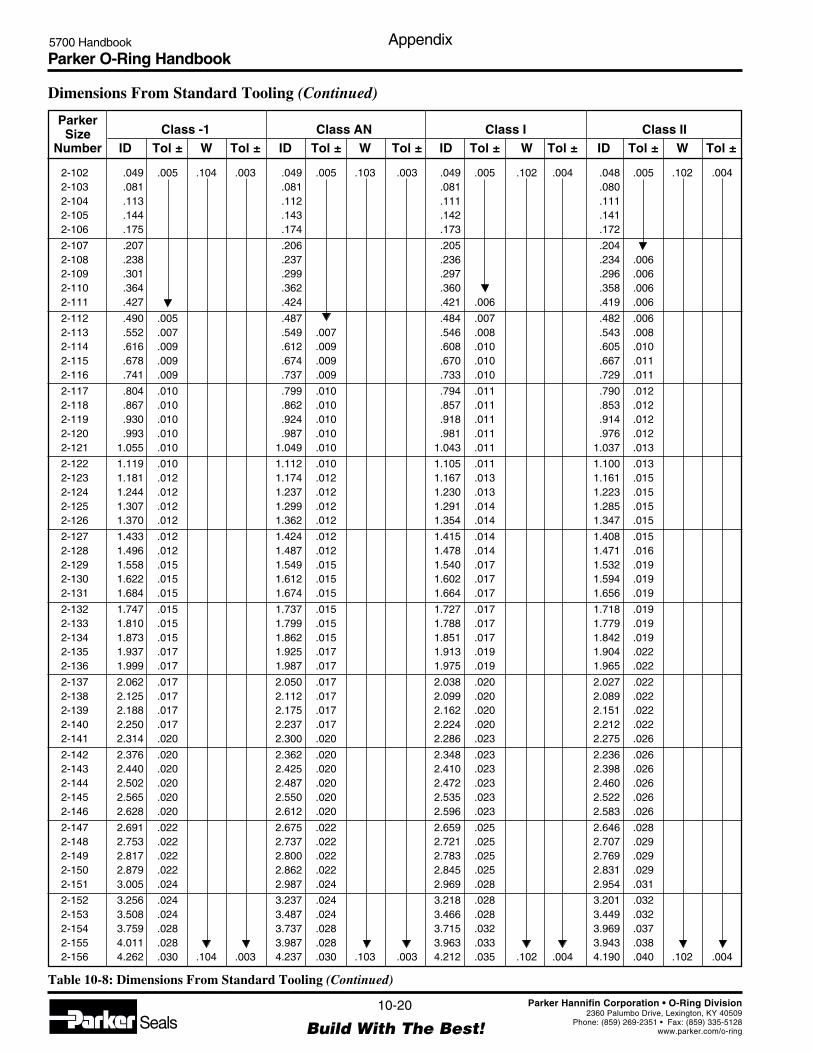
Parker O-Ring Handbook5700 Handbook Appendix
10-20
Build With The Best!SealsParker Hannifin Corporation • O-Ring Division
2360 Palumbo Drive, Lexington, KY 40509Phone: (859) 269-2351 • Fax: (859) 335-5128
www.parker.com/o-ring
2-102 .049 .005 .104 .003 .049 .005 .103 .003 .049 .005 .102 .004 .048 .005 .102 .0042-103 .081 .081 .081 .0802-104 .113 .112 .111 .1112-105 .144 .143 .142 .1412-106 .175 .174 .173 .172
2-107 .207 .206 .205 .2042-108 .238 .237 .236 .234 .0062-109 .301 .299 .297 .296 .0062-110 .364 .362 .360 .358 .0062-111 .427 .424 .421 .006 .419 .006
2-112 .490 .005 .487 .484 .007 .482 .0062-113 .552 .007 .549 .007 .546 .008 .543 .0082-114 .616 .009 .612 .009 .608 .010 .605 .0102-115 .678 .009 .674 .009 .670 .010 .667 .0112-116 .741 .009 .737 .009 .733 .010 .729 .011
2-117 .804 .010 .799 .010 .794 .011 .790 .0122-118 .867 .010 .862 .010 .857 .011 .853 .0122-119 .930 .010 .924 .010 .918 .011 .914 .0122-120 .993 .010 .987 .010 .981 .011 .976 .0122-121 1.055 .010 1.049 .010 1.043 .011 1.037 .013
2-122 1.119 .010 1.112 .010 1.105 .011 1.100 .0132-123 1.181 .012 1.174 .012 1.167 .013 1.161 .0152-124 1.244 .012 1.237 .012 1.230 .013 1.223 .0152-125 1.307 .012 1.299 .012 1.291 .014 1.285 .0152-126 1.370 .012 1.362 .012 1.354 .014 1.347 .015
2-127 1.433 .012 1.424 .012 1.415 .014 1.408 .0152-128 1.496 .012 1.487 .012 1.478 .014 1.471 .0162-129 1.558 .015 1.549 .015 1.540 .017 1.532 .0192-130 1.622 .015 1.612 .015 1.602 .017 1.594 .0192-131 1.684 .015 1.674 .015 1.664 .017 1.656 .019
2-132 1.747 .015 1.737 .015 1.727 .017 1.718 .0192-133 1.810 .015 1.799 .015 1.788 .017 1.779 .0192-134 1.873 .015 1.862 .015 1.851 .017 1.842 .0192-135 1.937 .017 1.925 .017 1.913 .019 1.904 .0222-136 1.999 .017 1.987 .017 1.975 .019 1.965 .022
2-137 2.062 .017 2.050 .017 2.038 .020 2.027 .0222-138 2.125 .017 2.112 .017 2.099 .020 2.089 .0222-139 2.188 .017 2.175 .017 2.162 .020 2.151 .0222-140 2.250 .017 2.237 .017 2.224 .020 2.212 .0222-141 2.314 .020 2.300 .020 2.286 .023 2.275 .026
2-142 2.376 .020 2.362 .020 2.348 .023 2.236 .0262-143 2.440 .020 2.425 .020 2.410 .023 2.398 .0262-144 2.502 .020 2.487 .020 2.472 .023 2.460 .0262-145 2.565 .020 2.550 .020 2.535 .023 2.522 .0262-146 2.628 .020 2.612 .020 2.596 .023 2.583 .026
2-147 2.691 .022 2.675 .022 2.659 .025 2.646 .0282-148 2.753 .022 2.737 .022 2.721 .025 2.707 .0292-149 2.817 .022 2.800 .022 2.783 .025 2.769 .0292-150 2.879 .022 2.862 .022 2.845 .025 2.831 .0292-151 3.005 .024 2.987 .024 2.969 .028 2.954 .031
2-152 3.256 .024 3.237 .024 3.218 .028 3.201 .0322-153 3.508 .024 3.487 .024 3.466 .028 3.449 .0322-154 3.759 .028 3.737 .028 3.715 .032 3.969 .0372-155 4.011 .028 3.987 .028 3.963 .033 3.943 .0382-156 4.262 .030 .104 .003 4.237 .030 .103 .003 4.212 .035 .102 .004 4.190 .040 .102 .004
Table 10-8: Dimensions From Standard Tooling (Continued)
Dimensions From Standard Tooling (Continued)
ParkerSize Class -1 Class AN Class I Class II
Number ID Tol ± W Tol ± ID Tol ± W Tol ± ID Tol ± W Tol ± ID Tol ± W Tol ±

Parker O-Ring Handbook5700 Handbook Appendix
10-21
Build With The Best!SealsParker Hannifin Corporation • O-Ring Division
2360 Palumbo Drive, Lexington, KY 40509Phone: (859) 269-2351 • Fax: (859) 335-5128
www.parker.com/o-ring
2-102 .048 .005 .101 .004 .048 .005 .101 .004 .048 .005 .100 .005 .047 .005 .100 .0052-103 .080 .005 .079 .005 .079 .005 .078 .0062-104 .110 .005 .110 .006 .109 .006 .109 .0062-105 .141 .006 .140 .006 .139 .006 .139 .0062-106 .171 .006 .170 .006 .169 .006 .169 .006
2-107 .203 .006 .202 .006 .201 .006 .200 .0062-108 .233 .006 .232 .006 .231 .006 .230 .0072-109 .294 .006 .293 .006 .291 .007 .290 .0072-110 .356 .006 .354 .007 .353 .007 .351 .0082-111 .417 .007 .415 .007 .413 .008 .411 .008
2-112 .479 .007 .477 .007 .474 .008 .472 .0092-113 .540 .009 .537 .010 .535 .011 .532 .0112-114 .602 .011 .599 .012 .596 .013 .593 .0132-115 .663 .011 .660 .012 .656 .013 .653 .0142-116 .725 .012 .722 .013 .718 .013 .714 .014
2-117 .786 .013 .782 .014 .778 .015 .774 .0162-118 .848 .013 .844 .014 .840 .015 .835 .0162-119 .909 .013 .905 .014 .900 .016 .895 .0172-120 .971 .014 .966 .015 .961 .016 .956 .0172-121 1.032 .014 1.027 .015 1.022 .016 1.016 .018
2-122 1.094 .014 1.089 .015 1.083 .017 1.078 .0182-123 1.155 .016 1.149 .018 1.143 .019 1.138 .0202-124 1.217 .016 1.211 .018 1.205 .019 1.199 .0212-125 1.278 .017 1.272 .018 1.265 .020 1.259 .0212-126 1.340 .017 1.333 .019 1.327 .020 1.320 .022
2-127 1.401 .017 1.394 .019 1.387 .021 1.380 .0222-128 1.463 .017 1.456 .019 1.448 .021 1.441 .0232-129 1.524 .021 1.516 .022 1.509 .024 1.501 .0262-130 1.586 .021 1.578 .023 1.570 .025 1.562 .0272-131 1.647 .021 1.639 .023 1.630 .025 1.622 .027
2-132 1.709 .021 1.701 .023 1.692 .025 1.683 .0282-133 1.770 .021 1.761 .024 1.752 .026 1.743 .0282-134 1.832 .022 1.823 .024 1.814 .026 1.804 .0282-135 1.894 .024 1.885 .026 1.875 .029 1.865 .0312-136 1.955 .024 1.945 .027 1.935 .029 1.925 .031
2-137 2.017 .024 2.007 .027 1.997 .029 1.986 .0322-138 2.078 .025 2.068 .027 2.057 .030 2.047 .0322-139 2.140 .025 2.129 .027 2.118 .030 2.108 .0332-140 2.201 .025 2.190 .028 2.179 .030 2.168 .0332-141 2.263 .028 2.252 .031 2.240 .034 2.229 .037
2-142 2.324 .029 2.312 .031 2.301 .034 2.289 .0372-143 2.386 .029 2.374 .032 2.362 .035 2.350 .0372-144 2.447 .029 2.435 .032 2.422 .035 2.410 .0382-145 2.509 .029 2.496 .032 2.484 .035 2.471 .0382-146 2.570 .029 2.557 .033 2.544 .036 2.531 .039
2-147 2.632 .032 2.619 .035 2.605 .038 2.592 .0412-148 2.693 .032 2.680 .035 2.666 .038 2.652 .0422-149 2.755 .032 2.741 .035 2.727 .039 2.713 .0422-150 2.816 .032 2.802 .036 2.788 .039 2.773 .0432-151 2.939 .035 2.924 .038 2.909 .042 2.894 .046
2-152 3.185 .036 3.169 .040 3.153 .043 3.137 .0472-153 3.431 .037 3.414 .041 3.396 .045 3.379 .0492-154 3.677 .041 3.659 .046 3.640 .050 3.621 .0552-155 3.923 .042 3.903 .047 3.883 .052 3.863 .0572-156 4.169 .045 .101 .004 4.148 .050 .101 .004 4.127 .055 .100 .005 4.106 .061 .100 .005
ParkerSize Class III Class IV Class V Class VI
Number ID Tol ± W Tol ± ID Tol ± W Tol ± ID Tol ± W Tol ± ID Tol ± W Tol ±
Table 10-8: Dimensions From Standard Tooling (Continued)
Dimensions From Standard Tooling (Continued)

Parker O-Ring Handbook5700 Handbook Appendix
10-22
Build With The Best!SealsParker Hannifin Corporation • O-Ring Division
2360 Palumbo Drive, Lexington, KY 40509Phone: (859) 269-2351 • Fax: (859) 335-5128
www.parker.com/o-ring
2-157 4.514 .030 .104 .003 4.487 .030 .103 .003 4.460 .035 .102 .004 4.438 .041 .102 .0042-158 4.765 .030 4.737 .030 4.709 .036 4.685 .0412-159 5.017 .035 4.987 .035 4.957 .041 4.932 .0472-160 5.268 .035 5.237 .035 5.206 .041 5.179 .0482-161 5.520 .035 5.487 .035 5.454 .042 5.427 .048
2-162 5.771 .035 5.737 .035 5.703 .042 5.674 .0492-163 6.023 .035 5.987 .035 5.951 .042 5.921 .0492-164 6.274 .040 6.237 .040 6.200 .047 6.168 .0552-165 6.526 .040 6.487 .040 6.448 .048 6.416 .0562-166 6.777 .040 6.737 .040 6.697 .048 6.663 .056
2-167 7.029 .040 6.987 .040 6.945 .048 6.910 .0572-168 7.280 .045 7.237 .045 7.194 .054 7.157 .0622-169 7.532 .045 7.487 .045 7.442 .054 7.405 .0632-170 7.783 .045 7.737 .045 7.691 .054 7.652 .0642-171 8.035 .045 7.987 .045 7.939 .055 7.899 .064
2-172 8.286 .050 8.237 .050 8.188 .060 8.146 .0702-173 8.538 .050 8.487 .050 8.436 .060 8.394 .0702-174 8.789 .050 8.737 .050 8.685 .060 8.641 .0712-175 9.041 .050 8.987 .050 8.933 .061 8.888 .0722-176 8.292 .055 9.237 .055 9.182 .066 9.135 .077
2-177 9.544 .055 9.487 .055 9.430 .066 9.383 .0782-178 9.795 .055 9.737 .055 9.679 .067 9.630 .0782-201 .172 .005 .140 .004 .171 .005 .139 .004 .170 .005 .138 .005 .169 .005 .137 .0052-202 .235 .005 .234 .005 .233 .005 .231 .0062-203 .298 .005 .296 .005 .294 .005 .293 .006
2-204 .361 .005 .359 .005 .357 .005 .355 .0062-205 .424 .005 .421 .005 .418 .006 .416 .0062-206 .487 .005 .484 .005 .481 .006 .479 .0072-207 .549 .007 .546 .007 .543 .008 .540 .0082-208 .613 .009 .609 .009 .605 .010 .602 .010
2-209 .675 .009 .671 .009 .667 .010 .664 .0112-210 .738 .010 .734 .010 .730 .011 .726 .0122-211 .801 .010 .796 .010 .791 .011 .787 .0122-212 .864 .010 .859 .010 .854 .011 .850 .0122-213 .927 .010 .921 .010 .915 .011 .911 .012
2-214 .990 .010 .984 .010 .978 .011 .973 .0122-215 1.052 .010 1.046 .010 1.040 .011 1.034 .0132-216 1.116 .012 1.109 .012 1.102 .013 1.097 .0152-217 1.178 .012 1.171 .012 1.164 .013 1.158 .0152-218 1.241 .012 1.234 .012 1.227 .013 1.220 .015
2-219 1.304 .012 1.296 .012 1.288 .014 1.282 .0152-220 1.367 .012 1.359 .012 1.351 .014 1.344 .0152-221 1.430 .012 1.421 .012 1.412 .014 1.405 .0152-222 1.493 .015 1.484 .015 1.475 .017 1.468 .0192-223 1.619 .015 1.609 .015 1.599 .017 1.591 .019
2-224 1.744 .015 1.734 .015 1.724 .017 1.715 .0192-225 1.870 .018 1.859 .018 1.848 .020 1.839 .0222-226 1.996 .018 1.984 .018 1.972 .020 1.962 .0232-227 2.122 .018 2.109 .018 2.096 .021 2.086 .0232-228 2.247 .020 2.234 .020 2.221 .023 2.209 .025
2-229 2.373 .020 2.359 .020 2.345 .023 2.333 .0262-230 2.499 .020 2.484 .020 2.469 .023 2.457 .0262-231 2.625 .020 2.609 .020 2.593 .023 2.580 .0262-232 2.750 .024 2.734 .024 2.718 .027 2.704 .0312-233 2.876 .024 .140 .004 2.859 .024 .139 .004 2.842 .027 .138 .005 2.828 .031 .137 .005
Table 10-8: Dimensions From Standard Tooling (Continued)
Dimensions From Standard Tooling (Continued)
ParkerSize Class -1 Class AN Class I Class II
Number ID Tol ± W Tol ± ID Tol ± W Tol ± ID Tol ± W Tol ± ID Tol ± W Tol ±

Parker O-Ring Handbook5700 Handbook Appendix
10-23
Build With The Best!SealsParker Hannifin Corporation • O-Ring Division
2360 Palumbo Drive, Lexington, KY 40509Phone: (859) 269-2351 • Fax: (859) 335-5128
www.parker.com/o-ring
2-157 4.416 .046 .101 .004 4.393 .052 .101 .004 4.370 .057 .100 .005 4.348 .062 .100 .0052-158 4.661 .047 4.638 .053 4.614 .058 4.590 .0642-159 4.907 .053 4.882 .059 4.857 .065 4.832 .0712-160 5.153 .054 5.127 .060 5.101 .066 5.075 .0732-161 5.399 .055 5.372 .061 5.344 .068 5.317 .075
2-162 5.645 .056 5.617 .063 5.588 .069 5.559 .0762-163 5.891 .057 5.861 .064 5.831 .071 5.801 .0782-164 6.137 .062 6.106 .070 6.075 .077 6.044 .0852-165 6.390 .063 6.351 .071 6.318 .079 6.286 .0872-166 6.629 .064 6.596 .072 6.562 .080 6.528 .089
2-167 6.875 .065 6.840 .074 6.805 .082 6.770 .0902-168 7.121 .071 7.085 .080 7.049 .088 7.013 .0972-169 7.367 .072 7.330 .081 7.292 .090 7.255 .0992-170 7.613 .073 7.575 .082 7.536 .091 7.497 .1012-171 7.859 .074 7.819 .083 7.779 .093 7.739 .103
2-172 8.105 .080 8.064 .090 8.023 .099 7.982 .1092-173 8.351 .081 8.309 .091 8.266 .101 8.224 .1112-174 8.597 .081 8.554 .092 8.510 .102 8.466 .1132-175 8.843 .082 8.798 .093 8.753 .104 8.708 .1152-176 9.089 .088 9.043 .099 8.997 .110 8.951 .122
2-177 9.335 .089 9.288 .101 9.240 .112 9.193 .1232-178 9.581 .090 9.533 .102 9.484 .113 9.435 .1252-201 .168 .006 .137 .005 .167 .006 .136 .006 .167 .006 .135 .006 .166 .006 .135 .0062-202 .230 .006 .229 .006 .228 .006 .227 .0072-203 .291 .006 .290 .006 .288 .007 .287 .007
2-204 .353 .006 .351 .007 .350 .007 .348 .0082-205 .414 .007 .412 .007 .410 .008 .408 .0082-206 .476 .007 .474 .007 .471 .008 .469 .0082-207 .537 .009 .535 .010 .532 .010 .529 .0112-208 .599 .011 .596 .012 .593 .013 .590 .013
2-209 .660 .011 .657 .012 .654 .013 .650 .0142-210 .722 .013 .719 .014 .715 .014 .711 .0152-211 .783 .013 .779 .014 .775 .015 .771 .0162-212 .845 .013 .841 .014 .837 .015 .832 .0162-213 .906 .013 .902 .014 .897 .016 .892 .017
2-214 .968 .014 .963 .015 .958 .016 .953 .0172-215 1.029 .014 1.024 .015 1.019 .016 1.014 .0182-216 1.091 .016 1.086 .017 1.080 .019 1.075 .0202-217 1.152 .016 1.146 .018 1.141 .019 1.135 .0202-218 1.214 .016 1.208 .018 1.202 .019 1.196 .021
2-219 1.275 .017 1.269 .018 1.262 .020 1.256 .0212-220 1.337 .017 1.330 .019 1.324 .020 1.317 .0222-221 1.398 .017 1.391 .019 1.384 .021 1.377 .0222-222 1.460 .020 1.453 .022 1.445 .024 1.438 .0262-223 1.583 .021 1.575 .023 1.567 .025 1.559 .027
2-224 1.706 .021 1.698 .023 1.689 .025 1.680 .0272-225 1.829 .025 1.820 .027 1.811 .029 1.801 .0312-226 1.952 .025 1.942 .028 1.932 .030 1.922 .0322-227 2.075 .026 2.065 .028 2.054 .031 2.044 .0332-228 2.198 .028 2.187 .031 2.176 .033 2.165 .036
2-229 2.321 .028 2.309 .031 2.298 .034 2.286 .0372-230 2.444 .029 2.432 .032 2.419 .035 2.407 .0382-231 2.567 .029 2.554 .033 2.541 .036 2.528 .0392-232 2.690 .034 2.677 .037 2.663 .040 2.649 .0442-233 2.813 .034 .137 .005 2.799 .038 .136 .006 2.785 .041 .135 .006 2.770 .045 .135 .006
ParkerSize Class III Class IV Class V Class VI
Number ID Tol ± W Tol ± ID Tol ± W Tol ± ID Tol ± W Tol ± ID Tol ± W Tol ±
Table 10-8: Dimensions From Standard Tooling (Continued)
Dimensions From Standard Tooling (Continued)

Parker O-Ring Handbook5700 Handbook Appendix
10-24
Build With The Best!SealsParker Hannifin Corporation • O-Ring Division
2360 Palumbo Drive, Lexington, KY 40509Phone: (859) 269-2351 • Fax: (859) 335-5128
www.parker.com/o-ring
2-234 3.002 .024 .140 .004 2.984 .024 .139 .004 2.966 .028 .138 .005 2.951 .031 .137 .0052-235 3.128 .024 3.109 .024 3.090 .028 3.075 .0312-236 3.253 .024 3.234 .024 3.215 .028 3.198 .0322-237 3.379 .024 3.359 .024 3.339 .028 3.322 .0322-238 3.505 .024 3.484 .024 3.463 .028 3.446 .032
2-239 3.631 .028 3.609 .028 3.587 .032 3.569 .0372-240 3.756 .028 3.734 .028 3.712 .032 3.693 .0372-241 3.882 .028 3.859 .028 3.836 .033 3.817 .0372-242 4.008 .028 3.984 .028 3.960 .033 3.940 .0382-243 4.134 .028 4.109 .028 4.084 .033 4.064 .038
2-244 4.259 .030 4.234 .030 4.209 .035 4.187 .0402-245 4.385 .030 4.359 .030 4.333 .035 4.311 .0402-246 4.511 .030 4.484 .030 4.457 .035 4.435 .0412-247 4.637 .030 4.609 .030 4.581 .036 4.558 .0412-248 4.762 .030 4.734 .030 4.706 .036 4.682 .041
2-249 4.888 .035 4.859 .035 4.830 .041 4.806 .0472-250 5.014 .035 4.984 .035 4.954 .041 4.929 .0472-251 5.140 .035 5.109 .035 5.078 .041 5.053 .0472-252 5.265 .035 5.234 .035 5.203 .041 5.176 .0482-253 5.391 .035 5.359 .035 5.327 .041 5.300 .048
2-254 5.517 .035 5.484 .035 5.451 .042 5.424 .0482-255 5.643 .035 5.609 .035 5.575 .042 5.547 .0482-256 5.768 .035 5.734 .035 5.700 .042 5.671 .0492-257 5.894 .035 5.859 .035 5.824 .042 5.795 .0492-258 6.020 .035 5.984 .035 5.948 .042 5.918 .049
2-259 6.271 .040 6.234 .040 6.197 .047 6.165 .0552-260 6.523 .040 6.484 .040 6.445 .048 6.413 .0562-261 6.774 .040 6.734 .040 6.694 .048 6.660 .0562-262 7.026 .040 6.984 .040 6.942 .048 6.907 .0572-263 7.277 .045 7.234 .045 7.191 .054 7.154 .062
2-264 7.529 .045 7.484 .045 7.439 .054 7.402 .0632-265 7.780 .045 7.734 .045 7.688 .054 7.649 .0642-266 8.032 .045 7.984 .045 7.936 .055 7.896 .0642-267 8.283 .050 8.234 .050 8.185 .060 8.143 .0702-268 8.535 .050 8.484 .050 8.433 .060 8.391 .070
2-269 8.786 .050 . 8.734 .050 8.682 .060 8.638 .0712-270 9.038 .050 8.984 .050 8.930 .061 8.885 .0722-271 9.289 .055 9.234 .055 9.179 .066 9.132 .0772-272 9.541 .055 9.484 .055 9.427 .066 9.380 .0782-273 9.792 .055 9.734 .055 9.676 .067 9.627 .078
2-274 10.044 .055 9.984 .055 9.924 .067 9.874 .0792-275 10.547 .055 10.484 .055 10.421 .068 10.369 .0802-276 11.050 .065 10.984 .065 10.918 .078 10.863 .0912-277 11.553 .065 11.484 .065 11.415 .079 11.358 .0932-278 12.056 .065 11.984 .065 11.912 .079 11.852 .094
2-279 13.062 .065 12.984 .065 12.906 .081 12.841 .0962-280 14.068 .065 13.984 .065 13.900 .082 13.830 .0992-281 15.074 .065 14.984 .065 14.894 .083 14.819 .1012-282 16.051 .075 15.955 .075 15.859 .095 15.779 .1132-283 17.057 .080 16.955 .080 16.853 .100 16.768 .121
2-284 18.063 .085 17.955 .085 17.847 .107 17.757 .1282-309 .414 .005 .211 .005 .412 .005 .210 .005 .410 .005 .209 .006 .407 .006 .208 .0072-310 .478 .005 .475 .005 .472 .006 .470 .0062-311 .540 .007 .537 .007 .534 .008 .531 .0082-312 .604 .009 .211 .005 .600 .009 .210 .005 .596 .010 .209 .006 .593 .010 .208 .007
Table 10-8: Dimensions From Standard Tooling (Continued)
Dimensions From Standard Tooling (Continued)
ParkerSize Class -1 Class AN Class I Class II
Number ID Tol ± W Tol ± ID Tol ± W Tol ± ID Tol ± W Tol ± ID Tol ± W Tol ±

Parker O-Ring Handbook5700 Handbook Appendix
10-25
Build With The Best!SealsParker Hannifin Corporation • O-Ring Division
2360 Palumbo Drive, Lexington, KY 40509Phone: (859) 269-2351 • Fax: (859) 335-5128
www.parker.com/o-ring
2-234 2.936 .035 .137 .005 2.921 .038 .136 .006 2.906 .042 .135 .006 2.891 .045 .135 .0062-235 3.059 .035 3.044 .039 3.028 .043 3.013 .0462-236 3.182 .036 3.166 .040 3.150 .043 3.134 .0472-237 3.305 .036 3.288 .040 3.272 .044 3.255 .0482-238 3.428 .037 3.411 .041 3.393 .045 3.376 .049
2-239 3.551 .041 3.533 .045 3.515 .050 3.497 .0542-240 3.674 .041 3.656 .046 3.637 .050 3.618 .0552-241 3.797 .042 3.778 .047 3.759 .051 3.739 .0562-242 3.920 .042 3.900 .047 3.880 .052 3.860 .0572-243 4.043 .043 4.023 .048 4.002 .053 3.982 .058
2-244 4.166 .045 4.145 .050 4.124 .055 4.103 .0602-245 4.289 .046 4.267 .051 4.245 .056 4.224 .0612-246 4.412 .046 4.390 .052 4.367 .057 4.345 .0622-247 4.535 .047 4.512 .052 4.489 .058 4.466 .0632-248 4.658 .047 4.635 .053 4.611 .058 4.587 .064
2-249 4.781 .052 4.757 .058 4.733 .064 4.708 .0702-250 4.904 .053 4.879 .059 4.854 .065 4.829 .0712-251 5.027 .053 5.002 .060 4.976 .066 4.951 .0722-252 5.150 .054 5.124 .060 5.098 .066 5.072 .0732-253 5.273 .054 5.246 .061 5.220 .067 5.193 .074
2-254 5.396 .055 5.369 .061 5.341 .068 5.314 .0742-255 5.519 .055 5.491 .062 5.463 .069 5.435 .0752-256 5.642 .056 5.614 .063 5.585 .069 5.556 .0762-257 5.765 .056 5.736 .063 5.707 .070 5.677 .0772-258 5.888 .057 5.858 .064 5.828 .071 5.798 .078
2-259 6.134 .062 6.103 .070 6.072 .077 6.041 .0852-260 6.380 .063 6.348 .071 6.315 .079 6.283 .0872-261 6.626 .064 6.593 .072 6.559 .080 6.525 .0882-262 6.872 .065 6.837 .074 6.802 .082 6.767 .0902-263 7.118 .071 7.082 .080 7.046 .088 7.010 .097
2-264 7.364 .072 7.327 .081 7.289 .090 7.252 .0992-265 7.610 .073 7.572 .082 7.533 .091 7.494 .1012-266 7.856 .074 7.816 .083 7.776 .093 7.736 .1022-267 8.102 .080 8.061 .090 8.020 .099 7.979 .1092-268 8.348 .081 8.306 .091 8.263 .101 8.221 .111
2-269 8.594 .081 8.551 .092 8.507 .102 8.463 .1132-270 8.840 .082 8.795 .093 8.750 .104 8.705 .1152-271 9.086 .088 9.040 .099 8.994 .110 8.948 .1212-272 9.332 .089 9.285 .101 9.237 .112 9.190 .1232-273 9.578 .090 9.530 .102 9.481 .113 9.432 .125
2-274 9.824 .091 9.774 .103 9.724 .115 9.674 .1272-275 10.316 .093 10.264 .105 10.211 .118 10.159 .1302-276 10.808 .105 10.753 .118 10.698 .131 10.643 .1442-277 11.300 .106 11.243 .120 11.185 .134 11.128 .1482-278 11.792 .108 11.732 .123 11.672 .137 11.612 .151
2-279 12.776 .112 12.711 .127 12.646 .143 12.581 .1582-280 13.760 .115 13.690 .132 13.620 .149 13.550 .1662-281 14.744 .119 14.669 .137 14.594 .155 14.519 .1732-282 15.700 .132 15.620 .152 15.540 .171 15.460 .1902-283 16.684 .141 16.599 .161 16.514 .182 16.429 .202
2-284 17.668 .150 17.578 .171 17.488 .193 17.398 .2142-309 .405 .006 .207 .007 .403 .007 .206 .007 .401 .007 .205 .008 .399 .008 .203 .0082-310 .467 .007 .465 .007 .463 .008 .460 .0082-311 .528 .009 .526 .010 .523 .010 .520 .0112-312 .590 .011 .207 .007 .587 .012 .206 .007 .584 .013 .205 .008 .581 .013 .203 .008
ParkerSize Class III Class IV Class V Class VI
Number ID Tol ± W Tol ± ID Tol ± W Tol ± ID Tol ± W Tol ± ID Tol ± W Tol ±
Table 10-8: Dimensions From Standard Tooling (Continued)
Dimensions From Standard Tooling (Continued)
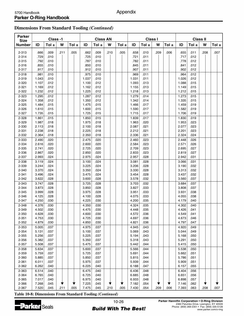
Parker O-Ring Handbook5700 Handbook Appendix
10-26
Build With The Best!SealsParker Hannifin Corporation • O-Ring Division
2360 Palumbo Drive, Lexington, KY 40509Phone: (859) 269-2351 • Fax: (859) 335-5128
www.parker.com/o-ring
2-313 .666 .009 .211 .005 .662 .009 .210 .005 .658 .010 .209 .006 .655 .011 .208 .0072-314 .729 .010 .725 .010 .721 .011 .717 .0122-315 .792 .010 .787 .010 .782 .011 .778 .0122-316 .855 .010 .850 .010 .845 .011 .841 .0122-317 .917 .010 .912 .010 .907 .011 .902 .012
2-318 .981 .010 .975 .010 .969 .011 .964 .0122-319 1.043 .010 1.037 .010 1.031 .011 1.026 .0122-320 1.107 .012 1.100 .012 1.093 .013 1.088 .0152-321 1.169 .012 1.162 .012 1.155 .013 1.149 .0152-322 1.232 .012 1.225 .012 1.218 .013 1.212 .015
2-323 1.295 .012 1.287 .012 1.279 .014 1.273 .0152-324 1.358 .012 1.350 .012 1.342 .014 1.335 .0152-325 1.484 .015 1.475 .015 1.466 .017 1.459 .0192-326 1.610 .015 1.600 .015 1.590 .017 1.582 .0192-327 1.735 .015 1.725 .015 1.715 .017 1.706 .019
2-328 1.861 .015 1.850 .015 1.839 .017 1.830 .0192-329 1.987 .018 1.975 .018 1.963 .020 1.953 .0232-330 2.113 .018 2.100 .018 2.087 .021 2.077 .0232-331 2.238 .018 2.225 .018 2.212 .021 2.201 .0232-332 2.364 .018 2.350 .018 2.336 .021 2.324 .024
2-333 2.490 .020 2.475 .020 2.460 .023 2.448 .0262-334 2.616 .020 2.600 .020 2.584 .023 2.571 .0262-335 2.741 .020 2.725 .020 2.709 .023 2.695 .0272-336 2.867 .020 2.850 .020 2.833 .023 2.819 .0272-337 2.993 .024 2.975 .024 2.957 .028 2.942 .031
2-338 3.119 .024 3.100 .024 3.081 .028 3.066 .0312-339 3.244 .024 3.225 .024 3.206 .028 3.190 .0322-340 3.370 .024 3.350 .024 3.330 .028 3.313 .0322-341 3.496 .024 3.475 .024 3.454 .028 3.437 .0322-342 3.622 .028 3.600 .028 3.578 .032 3.560 .037
2-343 3.747 .028 3.725 .028 3.703 .032 3.684 .0372-344 3.873 .028 3.850 .028 3.827 .033 3.808 .0372-345 3.999 .028 3.975 .028 3.951 .033 3.931 .0382-346 4.125 .028 4.100 .028 4.075 .033 4.055 .0382-347 4.250 .030 4.225 .030 4.200 .035 4.179 .040
2-348 4.376 .030 4.350 .030 4.324 .035 4.302 .0402-349 4.502 .030 4.475 .030 4.448 .035 4.426 .0412-350 4.628 .030 4.600 .030 4.572 .036 4.549 .0412-351 4.753 .030 4.725 .030 4.697 .036 4.673 .0462-352 4.879 .030 4.850 .030 4.821 .036 4.797 .047
2-353 5.005 .037 4.975 .037 4.945 .043 4.920 .0492-354 5.131 .037 5.100 .037 5.069 .043 5.044 .0492-355 5.256 .037 5.225 .037 5.194 .043 5.168 .0502-356 5.382 .037 5.350 .037 5.318 .043 5.291 .0502-357 5.508 .037 5.475 .037 5.442 .044 5.415 .050
2-358 5.634 .037 5.600 .037 5.566 .044 5.538 .0502-359 5.759 .037 5.725 .037 5.691 .044 5.662 .0512-360 5.885 .037 5.850 .037 5.815 .044 5.786 .0512-361 6.011 .037 5.975 .037 5.939 .044 5.909 .0512-362 6.262 .040 6.225 .040 6.188 .047 6.157 .055
2-363 6.514 .040 6.475 .040 6.436 .048 6.404 .0562-364 6.765 .040 6.725 .040 6.685 .048 6.651 .0562-365 7.017 .040 6.975 .040 6.933 .048 6.898 .0572-366 7.268 .045 7.225 .045 7.182 .054 7.146 .0622-367 7.520 .045 .211 .005 7.475 .045 .210 .005 7.430 .054 .209 .006 7.393 .063 .208 .007
Table 10-8: Dimensions From Standard Tooling (Continued)
Dimensions From Standard Tooling (Continued)
ParkerSize Class -1 Class AN Class I Class II
Number ID Tol ± W Tol ± ID Tol ± W Tol ± ID Tol ± W Tol ± ID Tol ± W Tol ±
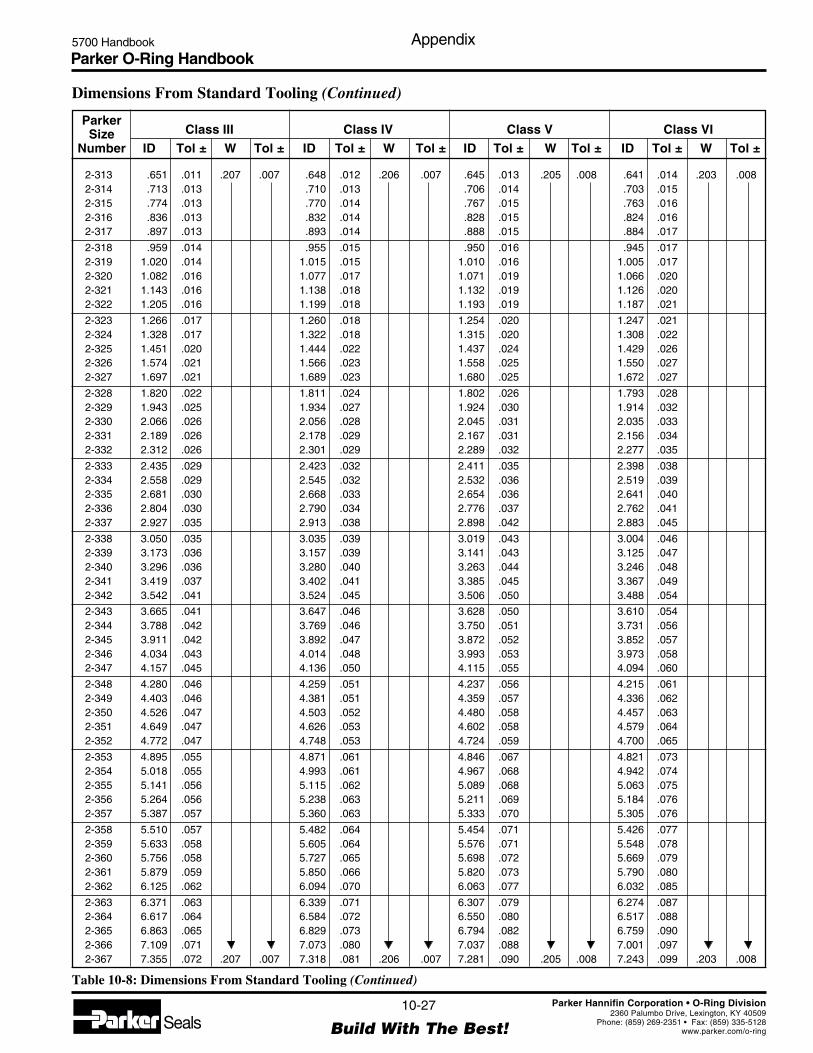
Parker O-Ring Handbook5700 Handbook Appendix
10-27
Build With The Best!SealsParker Hannifin Corporation • O-Ring Division
2360 Palumbo Drive, Lexington, KY 40509Phone: (859) 269-2351 • Fax: (859) 335-5128
www.parker.com/o-ring
2-313 .651 .011 .207 .007 .648 .012 .206 .007 .645 .013 .205 .008 .641 .014 .203 .0082-314 .713 .013 .710 .013 .706 .014 .703 .0152-315 .774 .013 .770 .014 .767 .015 .763 .0162-316 .836 .013 .832 .014 .828 .015 .824 .0162-317 .897 .013 .893 .014 .888 .015 .884 .017
2-318 .959 .014 .955 .015 .950 .016 .945 .0172-319 1.020 .014 1.015 .015 1.010 .016 1.005 .0172-320 1.082 .016 1.077 .017 1.071 .019 1.066 .0202-321 1.143 .016 1.138 .018 1.132 .019 1.126 .0202-322 1.205 .016 1.199 .018 1.193 .019 1.187 .021
2-323 1.266 .017 1.260 .018 1.254 .020 1.247 .0212-324 1.328 .017 1.322 .018 1.315 .020 1.308 .0222-325 1.451 .020 1.444 .022 1.437 .024 1.429 .0262-326 1.574 .021 1.566 .023 1.558 .025 1.550 .0272-327 1.697 .021 1.689 .023 1.680 .025 1.672 .027
2-328 1.820 .022 1.811 .024 1.802 .026 1.793 .0282-329 1.943 .025 1.934 .027 1.924 .030 1.914 .0322-330 2.066 .026 2.056 .028 2.045 .031 2.035 .0332-331 2.189 .026 2.178 .029 2.167 .031 2.156 .0342-332 2.312 .026 2.301 .029 2.289 .032 2.277 .035
2-333 2.435 .029 2.423 .032 2.411 .035 2.398 .0382-334 2.558 .029 2.545 .032 2.532 .036 2.519 .0392-335 2.681 .030 2.668 .033 2.654 .036 2.641 .0402-336 2.804 .030 2.790 .034 2.776 .037 2.762 .0412-337 2.927 .035 2.913 .038 2.898 .042 2.883 .045
2-338 3.050 .035 3.035 .039 3.019 .043 3.004 .0462-339 3.173 .036 3.157 .039 3.141 .043 3.125 .0472-340 3.296 .036 3.280 .040 3.263 .044 3.246 .0482-341 3.419 .037 3.402 .041 3.385 .045 3.367 .0492-342 3.542 .041 3.524 .045 3.506 .050 3.488 .054
2-343 3.665 .041 3.647 .046 3.628 .050 3.610 .0542-344 3.788 .042 3.769 .046 3.750 .051 3.731 .0562-345 3.911 .042 3.892 .047 3.872 .052 3.852 .0572-346 4.034 .043 4.014 .048 3.993 .053 3.973 .0582-347 4.157 .045 4.136 .050 4.115 .055 4.094 .060
2-348 4.280 .046 4.259 .051 4.237 .056 4.215 .0612-349 4.403 .046 4.381 .051 4.359 .057 4.336 .0622-350 4.526 .047 4.503 .052 4.480 .058 4.457 .0632-351 4.649 .047 4.626 .053 4.602 .058 4.579 .0642-352 4.772 .047 4.748 .053 4.724 .059 4.700 .065
2-353 4.895 .055 4.871 .061 4.846 .067 4.821 .0732-354 5.018 .055 4.993 .061 4.967 .068 4.942 .0742-355 5.141 .056 5.115 .062 5.089 .068 5.063 .0752-356 5.264 .056 5.238 .063 5.211 .069 5.184 .0762-357 5.387 .057 5.360 .063 5.333 .070 5.305 .076
2-358 5.510 .057 5.482 .064 5.454 .071 5.426 .0772-359 5.633 .058 5.605 .064 5.576 .071 5.548 .0782-360 5.756 .058 5.727 .065 5.698 .072 5.669 .0792-361 5.879 .059 5.850 .066 5.820 .073 5.790 .0802-362 6.125 .062 6.094 .070 6.063 .077 6.032 .085
2-363 6.371 .063 6.339 .071 6.307 .079 6.274 .0872-364 6.617 .064 6.584 .072 6.550 .080 6.517 .0882-365 6.863 .065 6.829 .073 6.794 .082 6.759 .0902-366 7.109 .071 7.073 .080 7.037 .088 7.001 .0972-367 7.355 .072 .207 .007 7.318 .081 .206 .007 7.281 .090 .205 .008 7.243 .099 .203 .008
ParkerSize Class III Class IV Class V Class VI
Number ID Tol ± W Tol ± ID Tol ± W Tol ± ID Tol ± W Tol ± ID Tol ± W Tol ±
Table 10-8: Dimensions From Standard Tooling (Continued)
Dimensions From Standard Tooling (Continued)
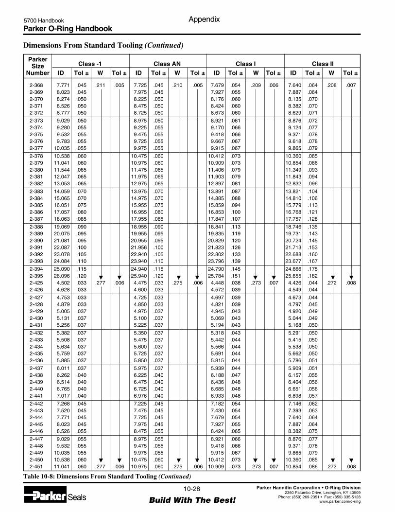
Parker O-Ring Handbook5700 Handbook Appendix
10-28
Build With The Best!SealsParker Hannifin Corporation • O-Ring Division
2360 Palumbo Drive, Lexington, KY 40509Phone: (859) 269-2351 • Fax: (859) 335-5128
www.parker.com/o-ring
2-368 7.771 .045 .211 .005 7.725 .045 .210 .005 7.679 .054 .209 .006 7.640 .064 .208 .0072-369 8.023 .045 7.975 .045 7.927 .055 7.887 .0642-370 8.274 .050 8.225 .050 8.176 .060 8.135 .0702-371 8.526 .050 8.475 .050 8.424 .060 8.382 .0702-372 8.777 .050 8.725 .050 8.673 .060 8.629 .071
2-373 9.029 .050 8.975 .050 8.921 .061 8.876 .0722-374 9.280 .055 9.225 .055 9.170 .066 9.124 .0772-375 9.532 .055 9.475 .055 9.418 .066 9.371 .0782-376 9.783 .055 9.725 .055 9.667 .067 9.618 .0782-377 10.035 .055 9.975 .055 9.915 .067 9.865 .079
2-378 10.538 .060 10.475 .060 10.412 .073 10.360 .0852-379 11.041 .060 10.975 .060 10.909 .073 10.854 .0862-380 11.544 .065 11.475 .065 11.406 .079 11.349 .0932-381 12.047 .065 11.975 .065 11.903 .079 11.843 .0942-382 13.053 .065 12.975 .065 12.897 .081 12.832 .096
2-383 14.059 .070 13.975 .070 13.891 .087 13.821 .1042-384 15.065 .070 14.975 .070 14.885 .088 14.810 .1062-385 16.051 .075 15.955 .075 15.859 .094 15.779 .1132-386 17.057 .080 16.955 .080 16.853 .100 16.768 .1212-387 18.063 .085 17.955 .085 17.847 .107 17.757 .128
2-388 19.069 .090 18.955 .090 18.841 .113 18.746 .1352-389 20.075 .095 19.955 .095 19.835 .119 19.731 .1432-390 21.081 .095 20.955 .095 20.829 .120 20.724 .1452-391 22.087 .100 21.956 .100 21.823 .126 21.713 .1532-392 23.078 .105 22.940 .105 22.802 .133 22.688 .1602-393 24.084 .110 23.940 .110 23.796 .139 23.677 .167
2-394 25.090 .115 24.940 .115 24.790 .145 24.666 .1752-395 26.096 .120 25.940 .120 25.784 .151 25.655 .1822-425 4.502 .033 .277 .006 4.475 .033 .275 .006 4.448 .038 .273 .007 4.426 .044 .272 .0082-426 4.628 .033 4.600 .033 4.572 .039 4.549 .044
2-427 4.753 .033 4.725 .033 4.697 .039 4.673 .0442-428 4.879 .033 4.850 .033 4.821 .039 4.797 .0452-429 5.005 .037 4.975 .037 4.945 .043 4.920 .0492-430 5.131 .037 5.100 .037 5.069 .043 5.044 .0492-431 5.256 .037 5.225 .037 5.194 .043 5.168 .050
2-432 5.382 .037 5.350 .037 5.318 .043 5.291 .0502-433 5.508 .037 5.475 .037 5.442 .044 5.415 .0502-434 5.634 .037 5.600 .037 5.566 .044 5.538 .0502-435 5.759 .037 5.725 .037 5.691 .044 5.662 .0502-436 5.885 .037 5.850 .037 5.815 .044 5.786 .051
2-437 6.011 .037 5.975 .037 5.939 .044 5.909 .0512-438 6.262 .040 6.225 .040 6.188 .047 6.157 .0552-439 6.514 .040 6.475 .040 6.436 .048 6.404 .0562-440 6.765 .040 6.725 .040 6.685 .048 6.651 .0562-441 7.017 .040 6.976 .040 6.933 .048 6.898 .057
2-442 7.268 .045 7.225 .045 7.182 .054 7.146 .0622-443 7.520 .045 7.475 .045 7.430 .054 7.393 .0632-444 7.771 .045 7.725 .045 7.679 .054 7.640 .0642-445 8.023 .045 7.975 .045 7.927 .055 7.887 .0642-446 8.526 .055 8.475 .055 8.424 .065 8.382 .075
2-447 9.029 .055 8.975 .055 8.921 .066 8.876 .0772-448 9.532 .055 9.475 .055 9.418 .066 9.371 .0782-449 10.035 .055 9.975 .055 9.915 .067 9.865 .0792-450 10.538 .060 10.475 .060 10.412 .073 10.360 .0852-451 11.041 .060 .277 .006 10.975 .060 .275 .006 10.909 .073 .273 .007 10.854 .086 .272 .008
Table 10-8: Dimensions From Standard Tooling (Continued)
Dimensions From Standard Tooling (Continued)
ParkerSize Class -1 Class AN Class I Class II
Number ID Tol ± W Tol ± ID Tol ± W Tol ± ID Tol ± W Tol ± ID Tol ± W Tol ±

Parker O-Ring Handbook5700 Handbook Appendix
10-29
Build With The Best!SealsParker Hannifin Corporation • O-Ring Division
2360 Palumbo Drive, Lexington, KY 40509Phone: (859) 269-2351 • Fax: (859) 335-5128
www.parker.com/o-ring
2-368 7.601 .073 .207 .007 7.563 .082 .206 .007 7.524 .091 .205 .008 7.486 .101 .203 .0082-369 7.847 .074 7.808 .083 7.768 .093 7.728 .1022-370 8.093 .080 8.052 .089 8.011 .099 7.970 .1092-371 8.339 .081 8.297 .091 8.255 .101 8.212 .1112-372 8.585 .081 8.542 .092 8.498 .102 8.455 .133
2-373 8.831 .082 8.787 .093 8.742 .104 8.697 .1152-374 9.077 .088 9.031 .099 8.985 .110 8.939 .1212-375 9.323 .089 9.276 .100 9.229 .112 9.181 .1232-376 9.569 .090 9.521 .102 9.472 .113 9.424 .1252-377 9.815 .091 9.766 .103 9.716 .115 9.666 .127
2-378 10.307 .098 10.255 .110 10.203 .123 10.150 .1352-379 10.799 .100 10.745 .113 10.690 .126 10.635 .1392-380 11.291 .106 11.234 .120 11.177 .134 11.119 .1482-381 11.783 .108 11.724 .122 11.664 .137 11.604 .1512-382 12.767 .112 12.703 .127 12.638 .143 12.573 .158
2-383 13.751 .120 13.682 .137 13.612 .154 13.542 .1712-384 14.735 .124 14.661 .142 14.586 .160 14.511 .1782-385 15.700 .132 15.620 .152 15.540 .171 15.460 .1902-386 16.684 .141 16.599 .161 16.514 .182 16.429 .2022-387 17.668 .150 17.578 .161 17.488 .193 17.398 .214
2-388 18.652 .158 18.557 .181 18.462 .204 18.367 .2262-389 19.636 .167 19.536 .191 19.436 .216 19.336 .2392-390 20.620 .170 20.515 .196 20.410 .221 20.305 .2462-391 21.604 .179 21.494 .205 21.384 .232 21.274 .2582-392 22.573 .188 22.458 .215 22.343 .243 22.229 .270
2-393 23.557 .196 23.437 .225 23.318 .254 23.198 .2822-934 24.541 .205 24.416 .235 24.292 .265 24.167 .2952-395 25.525 .213 .207 .007 25.395 .244 .206 .007 25.266 .276 .205 .008 25.136 .307 .203 .0082-425 4.403 .049 .271 .008 4.381 .051 .269 .009 4.359 .060 .268 .009 4.336 .065 .266 .0092-426 4.526 .050 4.503 .055 4.480 .061 4.457 .066
2-427 4.649 .050 4.626 .056 4.602 .061 4.579 .0672-428 4.772 .050 4.748 .056 4.724 .062 4.700 .0682-429 4.895 .055 4.871 .061 4.846 .067 4.821 .0732-430 5.018 .055 4.993 .061 4.967 .068 4.942 .0742-431 5.141 .056 5.115 .062 5.089 .068 5.063 .075
2-432 5.264 .056 5.238 .063 5.211 .069 5.184 .0762-433 5.387 .057 5.360 .063 5.333 .070 5.305 .0762-434 5.510 .057 5.482 .064 5.454 .071 5.426 .0772-435 5.633 .058 5.605 .064 5.576 .071 5.548 .0782-436 5.756 .058 5.727 .065 5.698 .072 5.669 .079
2-437 5.879 .059 5.850 .066 5.820 .073 5.790 .0802-438 6.125 .062 6.094 .070 6.063 .077 6.032 .0852-439 6.371 .063 6.339 .071 6.307 .079 6.274 .0872-440 6.617 .064 6.584 .072 6.550 .080 6.517 .0882-441 6.863 .065 6.829 .073 6.794 .082 6.759 .090
2-442 7.109 .071 7.073 .080 7.037 .088 7.001 .0972-443 7.355 .072 7.318 .081 7.281 .090 7.243 .0992-444 7.601 .073 7.563 .082 7.524 .091 7.486 .1012-445 7.847 .074 7.808 .083 7.768 .093 7.728 .1022-446 8.339 .086 8.297 .096 8.255 .106 8.212 .116
2-447 8.831 .087 8.787 .098 8.742 .109 8.697 .1202-448 9.323 .089 9.276 .100 9.229 .112 9.181 .1232-449 9.815 .091 9.766 .103 9.716 .115 9.666 .1272-450 10.307 .098 10.255 .110 10.203 .123 10.150 .1352-451 10.799 .100 .271 .008 10.745 .113 .269 .009 10.690 .126 .268 .009 10.635 .139 .266 .009
ParkerSize Class III Class IV Class V Class VI
Number ID Tol ± W Tol ± ID Tol ± W Tol ± ID Tol ± W Tol ± ID Tol ± W Tol ±
Table 10-8: Dimensions From Standard Tooling (Continued)
Dimensions From Standard Tooling (Continued)

Parker O-Ring Handbook5700 Handbook Appendix
10-30
Build With The Best!SealsParker Hannifin Corporation • O-Ring Division
2360 Palumbo Drive, Lexington, KY 40509Phone: (859) 269-2351 • Fax: (859) 335-5128
www.parker.com/o-ring
2-452 11.544 .060 .277 .006 11.475 .060 .275 .006 11.406 .074 .273 .007 11.349 .088 .272 .0082-453 12.047 .060 11.975 .060 11.903 .074 11.843 .0892-454 12.550 .060 12.475 .060 12.400 .075 12.338 .0902-455 13.053 .060 12.975 .060 12.897 .076 12.832 .0912-456 13.556 .070 13.475 .070 13.394 .086 13.327 .102
2-457 14.059 .070 13.975 .070 13.891 .087 13.821 .1042-458 14.562 .070 14.475 .070 14.388 .087 14.316 .1052-459 15.065 .070 14.975 .070 14.885 .088 14.810 .1062-460 15.568 .070 15.475 .070 15.382 .089 15.305 .1072-461 16.051 .075 15.955 .075 15.859 .094 15.779 .113
2-462 16.554 .075 16.455 .075 16.356 .095 16.274 .1142-463 17.057 .080 16.955 .080 16.853 .100 16.768 .1212-464 17.560 .085 17.455 .085 17.350 .106 17.263 .1272-465 18.063 .085 17.955 .085 17.847 .107 17.757 .1282-466 18.566 .085 18.455 .085 18.344 .107 18.252 .129
2-467 19.069 .090 18.955 .090 18.841 .113 18.746 .1352-468 19.572 .090 19.455 .090 19.338 .113 19.241 .1372-469 20.075 .095 19.955 .095 19.835 .119 19.735 .1432-470 21.081 .095 20.955 .095 20.829 .120 20.724 .1452-471 22.087 .100 21.955 .100 21.823 .126 21.713 .153
2-472 23.078 .105 22.940 .105 22.802 .133 22.688 .1602-473 24.084 .110 23.940 .110 23.796 .139 23.677 .1672-474 25.090 .115 24.940 .115 24.790 .145 24.666 .1752-475 26.096 .120 .277 .006 25.940 .120 .275 .006 25.784 .151 .273 .007 25.655 .182 .272 .008
Table 10-8: Dimensions From Standard Tooling (Continued)
Dimensions From Standard Tooling (Continued)
ParkerSize Class -1 Class AN Class I Class II
Number ID Tol ± W Tol ± ID Tol ± W Tol ± ID Tol ± W Tol ± ID Tol ± W Tol ±
3-901 .186 .005 .056 .003 .185 .005 .056 .003 .184 .005 .056 .004 .183 .005 .055 .0043-902 .240 .005 .064 .239 .005 .064 .238 .005 .064 .236 .006 .0633-903 .303 .005 .064 .301 .005 .064 .299 .005 .064 .298 .006 .0633-904 .353 .005 .072 .351 .005 .072 .349 .005 .072 .347 .006 .0713-905 .416 .005 .072 .414 .005 .072 .412 .005 .072 .409 .006 .071
3-906 .471 .005 .078 .468 .005 .078 .465 .006 .078 .463 .006 .0773-907 .533 .007 .082 .530 .007 .082 .527 .008 .082 .524 .008 .0813-908 .648 .009 .088 .644 .009 .087 .640 .010 .086 .637 .011 .0863-909 .710 .009 .098 .706 .009 .097 .702 .010 .096 .698 .011 .0963-910 .760 .009 .098 .755 .009 .097 .750 .010 .096 .747 .011 .096
3-911 .868 .009 .117 .863 .009 .116 .858 .010 .115 .854 .011 .1153-912 .930 .009 .117 .924 .009 .116 .918 .010 .115 .914 .011 .1153-913 .992 .010 .117 .986 .010 .116 .980 .011 .115 .975 .012 .1153-914 1.053 .010 .117 1.047 .010 .116 1.041 .011 .115 1.035 .013 .1153-916 1.178 .010 .117 1.171 .010 .116 1.164 .011 .115 1.158 .013 .115
3-918 1.363 .012 .117 1.355 .012 .116 1.347 .014 .115 1.340 .015 .1153-920 1.484 .014 .119 1.475 .014 .118 1.466 .016 .117 1.459 .018 .1173-924 1.730 .014 .119 1.720 .014 .118 1.710 .016 .117 1.701 .018 .1173-928 2.103 .018 .119 2.090 .018 .118 2.077 .021 .117 2.067 .023 .1173-932 2.351 .018 .119 .004 2.337 .018 .118 .004 2.323 .021 .117 .005 2.311 .024 .117 .005
ParkerSize Class -1 Class AN Class I Class II
Number ID Tol ± W Tol ± ID Tol ± W Tol ± ID Tol ± W Tol ± ID Tol ± W Tol ±

Parker O-Ring Handbook5700 Handbook Appendix
10-31
Build With The Best!SealsParker Hannifin Corporation • O-Ring Division
2360 Palumbo Drive, Lexington, KY 40509Phone: (859) 269-2351 • Fax: (859) 335-5128
www.parker.com/o-ring
2-452 11.291 .101 .271 .008 11.234 .115 .269 .009 11.177 .129 .268 .009 11.119 .143 .266 .0092-453 11.783 .103 11.724 .117 11.664 .132 11.604 .1462-454 12.275 .105 12.213 .120 12.151 .135 12.088 .1502-455 12.767 .107 12.703 .122 12.638 .138 12.573 .1532-456 13.259 .119 13.192 .135 13.125 .151 13.057 .167
2-457 13.751 .120 13.682 .137 13.612 .154 13.542 .1702-458 14.243 .122 14.171 .139 14.099 .157 14.026 .1742-459 14.735 .124 14.661 .142 14.586 .160 14.511 .1812-460 15.227 .126 15.150 .144 15.073 .163 14.995 .1812-461 15.700 .132 15.620 .152 15.540 .171 15.460 .190
2-462 16.192 .134 16.109 .154 16.027 .174 15.945 .1932-463 16.684 .141 16.599 .161 16.514 .182 16.429 .2022-464 17.176 .148 17.088 .169 17.001 .190 16.914 .2112-465 17.668 .150 17.578 .171 17.488 .193 17.398 .2142-466 18.160 .151 18.067 .174 17.975 .196 17.883 .218
2-467 18.652 .158 18.557 .181 18.462 .204 18.367 .2262-468 19.144 .160 19.046 .183 18.949 .207 18.852 .2302-469 19.636 .167 19.536 .191 19.436 .215 19.336 .2392-470 20.620 .170 20.515 .196 20.410 .221 20.305 .2462-471 21.604 .179 21.494 .205 21.384 .232 21.274 .258
2-472 22.573 .188 22.458 .215 22.344 .243 22.229 .2702-473 23.557 .196 23.437 .225 23.318 .254 23.198 .2822-474 23.541 .205 24.416 .235 24.292 .265 24.167 .2952-475 25.525 .213 .271 .008 25.395 .245 .269 .009 25.266 .276 .268 .009 25.136 .307 .266 .009
ParkerSize Class III Class IV Class V Class VI
Number ID Tol ± W Tol ± ID Tol ± W Tol ± ID Tol ± W Tol ± ID Tol ± W Tol ±
Dimensions From Standard Tooling (Continued)
Table 10-8: Dimensions From Standard Tooling (Continued)
3-901 .182 .006 .055 .004 .181 .006 .055 .004 .180 .006 .055 .004 .179 .006 .054 .0043-902 .235 .006 .063 .234 .006 .063 .233 .006 .062 .232 .007 .0633-903 .296 .006 .063 .295 .006 .063 .293 .007 .062 .292 .007 .0623-904 .345 .006 .071 .344 .007 .070 .342 .007 .070 .340 .008 .0703-905 .407 .006 .071 .405 .007 .070 .403 .007 .070 .401 .008 .070
3-906 .461 .007 .077 .458 .007 .076 .456 .008 .076 .453 .008 .0763-907 .522 .009 .081 .519 .010 .080 .516 .010 .080 .514 .011 .0793-908 .634 .011 .086 .630 .012 .085 .627 .013 .085 .624 .014 .0843-909 .695 .012 .095 .691 .012 .095 .688 .013 .094 .684 .014 .0943-910 .743 .012 .095 .004 .739 .013 .095 .004 .735 .014 .094 .004 .732 .014 .094 .004
3-911 .849 .012 .114 .005 .845 .013 .114 .005 .841 .014 .113 .006 .836 .015 .112 .0063-912 .909 .012 .114 .905 .013 .114 .900 .015 .113 .895 .016 .1133-913 .970 .014 .114 .965 .015 .114 .960 .016 .113 .955 .017 .1133-914 1.030 .014 .114 1.025 .015 .114 1.020 .016 .113 1.015 .018 .1133-916 1.152 .014 .114 1.146 .016 .114 1.141 .017 .113 1.135 .018 .113
3-918 1.333 .017 .114 1.327 .019 .114 1.320 .020 .113 1.313 .022 .1133-920 1.451 .019 .116 1.444 .021 .116 1.437 .023 .115 1.429 .025 .1143-924 1.692 .020 .116 1.684 .022 .116 1.675 .024 .115 1.667 .026 .1143-928 2.057 .026 .116 2.046 .028 .116 2.036 .031 .115 2.025 .033 .1143-932 2.300 .026 .116 .005 2.288 .029 .116 .005 2.276 .032 .115 .006 2.265 .035 .114 .006
ParkerSize Class III Class IV Class V Class VI
Number ID Tol ± W Tol ± ID Tol ± W Tol ± ID Tol ± W Tol ± ID Tol ± W Tol ±

Parker O-Ring Handbook5700 Handbook Appendix
10-32
Build With The Best!SealsParker Hannifin Corporation • O-Ring Division
2360 Palumbo Drive, Lexington, KY 40509Phone: (859) 269-2351 • Fax: (859) 335-5128
www.parker.com/o-ring
Cross Section Tolerances
Shrinkage Class ToleranceW Cross Section –1 AN +I +II +III +IV +V +VI
Range – in. ± inches
.025 – .097 .003 .003 .004 .004 .004 .004 .004 .004
.098 – .104 .003 .003 .004 .004 .004 .004 .005 .005
.105 – .129 .004 .004 .005 .005 .005 .005 .006 .006
.130 – .149 .004 .004 .005 .005 .005 .006 .006 .006
.150 – .174 .005 .005 .006 .006 .007 .007 .007 .008
.175 – .220 .005 .005 .006 .007 .007 .007 .008 .008
.221 – .250 .006 .006 .007 .008 .008 .009 .009 .009
.251 – .300 .006 .006 .007 .008 .008 .009 .010 .010
.301 – .340 .007 .007 .008 .010 .010 .010 .011 .011
.341 – .375 .007 .007 .008 .010 .010 .011 .011 .011
W Cross Section –1 AN +I +II +III +IV +V +VIRange – mm. ± millimeters
.63 – 2.47 .08 .08 .10 .10 .10 .10 .10 .102.48 – 2.65 .08 .08 .10 .10 .10 .10 .13 .132.60 – 3.29 .10 .10 .13 .13 .13 .13 .15 .153.30 – 3.80 .10 .10 .13 .13 .13 .15 .15 .153.81 – 4.43 .13 .13 .15 .15 .18 .18 .18 .204.44 – 5.60 .13 .13 .15 .18 .18 .18 .20 .205.61 – 6.36 .15 .15 .18 .20 .20 .23 .23 .236.37 – 7.64 .15 .15 .18 .20 .20 .23 .25 .257.65 – 8.65 .18 .18 .20 .25 .25 .25 .28 .288.66 – 9.55 .18 .18 .20 .25 .25 .28 .28 .28
Table 10-9: Cross Section Tolerances
Shrinkage Class Factors
Shrinkage Dimension ToleranceClass Factor Factor
-1 1.006 0AN 1.000 0+I .994 .0012+II .989 .0024+III .984 .0036+IV .979 .0048+V .974 .0060+VI .969 .0072
Table 10-10: Shrinkage Class Factors

Parker O-Ring Handbook5700 Handbook Appendix
10-33
Build With The Best!SealsParker Hannifin Corporation • O-Ring Division
2360 Palumbo Drive, Lexington, KY 40509Phone: (859) 269-2351 • Fax: (859) 335-5128
www.parker.com/o-ring
Tolerances for Special O-Rings with Standard Shrinkage Rates
.027 – .060 .004 .68 – 1.53 .10
.061 – .490 .005 1.54 – 11.69 .13
.491 – .530 .006 11.70 – 14.49 .15
.531 – .690 .007 14.50 – 17.54 .18
.691 – .810 .008 17.55 – 20.59 .20
.811 – .940 .009 20.60 – 23.89 .23
.941 – 1.130 .010 23.90 – 28.71 .251.131 – 1.400 .012 28.72 – 35.57 .301.401 – 1.700 .014 35.58 – 43.17 .361.701 – 2.000 .016 43.20 – 50.81 .412.001 – 2.300 .018 50.82 – 58.43 .462.301 – 2.620 .020 58.44 – 66.56 .512.621 – 2.950 .022 66.57 – 74.94 .562.951 – 3.290 .024 74.95 – 83.57 .613.291 – 3.630 .026 83.58 – 92.21 .663.631 – 4.000 .028 92.22 – 101.61 .71
4.001 – 4.620 .030 101.62 – 117.36 .764.621 – 5.560 .035 117.37 – 141.23 .895.561 – 6.550 .040 141.24 – 166.39 1.026.551 – 7.560 .045 166.40 – 192.03 1.147.561 – 8.610 .050 192.04 – 218.70 1.278.611 – 9.975 .055 218.71 – 246.39 1.409.976 – 11.400 .060 246.40 – 289.57 1.52
11.401 – 13.700 .070 289.58 – 347.99 1.7813.701 – 16.100 .080 348.00 – 408.95 2.0316.101 – 18.600 .090 408.96 – 472.45 2.2918.601 – 22.500 .100 472.46 – 571.51 2.5422.501 – 28.000 .120 571.52 – 711.21 3.0528.001 – 33.700 .140 711.22 – 855.99 3.5633.701 – 39.600 .160 856.00 – 1005.85 4.0639.601 – 45.800 .180 1005.86 – 1163.66 4.5745.801 – 52.000 .200 1163.34 – 1320.80 5.08
Inside Dia. Tol. Inside Dia. Tol.(in.) (in.) (mm) (mm)
Inside Dia. Tol. Inside Dia. Tol.(in.) (in.) (mm) (mm)
Table 10-11: Tolerances for Special O-Rings with Standard Shrinkage Rates
Parker O-Ring Handbook5700 Handbook Index
11-1
Build With The Best!SealsParker Hannifin Corporation • O-Ring Division
2360 Palumbo Drive, Lexington, KY 40509Phone: (859) 269-2351 • Fax: (859) 335-5128
www.parker.com/o-ring
Index
Compression Force ............................................................... 3-9Concentrates Containing Mineral Oils
(Oil-in-Water-Solutions) ................................................... 3-16Contact Surfaces, Plastic .................................................... 3-22Cooling & Heating Systems ............................................... 3-11Corrosion ............................................................................ 2-20Crush Installation .................................................................. 1-6Cure Date ............................................................................ 2-24Cushion Installation .............................................................. 1-6Custom Molded Shapes ........................................................ 1-7
— D —Design, Pioneering .............................................................2-25Design Procedure
Recommended Design Procedure .................................. 1-7Recommended Manual Design Procedure .................... 1-8
Deterioration ....................................................................... 2-20Dimensions from Standard Tooling .................................. 10-18Dovetail and Half-Dovetail Grooves .................................... 4-3
Dovetail Grooves ......................................................... 4-15Half Dovetail Grooves .................................................4-16
Drive Belt CompoundsAvailable ...................................................................... 3-25Selection ...................................................................... 3-25
Drive Belts ..........................................................................3-25O-Rings as Drive Belts .................................................. 1-7
Dynamic Vacuum Sealing ................................................... 5-48
— E —Effects of Environment on Testing .....................................2-23Effects on Properties ........................................................... 2-23Elastomer .............................................................................. 2-4
Elastomer Compatibility Index ................................... 2-26Elastomers ..................................................................... 2-3Elastomers for O-Ring Seals ......................................... 2-4Introduction to Elastomers ............................................ 2-3
Electrical Properties ............................................................ 2-22Elongation ........................................................................... 2-16Engine ................................................................................. 3-10Environment, effects on properties .....................................2-23Epichlorohydrin (CO, ECO) ................................................. 2-7Ethylene Acrylate (AEM) ..................................................... 2-5Ethylene Propylene Rubber (EPM, EPDM) ......................... 2-5Excessive Swell (above 20%) ............................................. 5-17Explosive Decompression ..................................................10-4Extrusion ............................................................................... 3-4
Extrusion and Nibbling ............................................... 10-2
— F —Face Seal Glands ................................................................ 4-14
Face Type O-Ring Seals ................................................ 4-3Factors Applying to All O-Ring Types ................................. 3-3
— A —Abbreviations ....................................................................10-15Abrasion ............................................................................. 10-4
Abrasion Resistance .................................................... 2-17Acids ................................................................................... 3-22Acrylonitrile-Butadiene (NBR) ............................................ 2-4Advantages of O-Rings ........................................................ 1-2Aerospace Technology ........................................................3-13Age Control ........................................................................ 2-24Aging .................................................................................. 2-23Air Conditioning ................................................................. 3-12Compound Specifications For Commonly Used .................. 8-6Aniline Point Differences ................................................... 2-25Anti-Extrusion Device Design Hints .................................... 6-2Applications Summary .......................................................3-26Assembly .............................................................................. 3-6
Assembly Hints ........................................................... 10-5Automotive ........................................................................... 3-9
— B —Back-Up Rings ...................................................................5-17
Back-Up Ring Materials, Other ..................................... 6-3Polytetrafluoroethylene (PTFE) Back-Up Rings .......... 6-3
Boss Seals ............................................................................. 4-3Boss Seals, Tube Fitting .............................................. 4-17
Brake System ...................................................................... 3-10Break-Out Friction ................................................................ 5-8Butadiene Rubber (BR) ........................................................ 2-6Butyl Rubber (IIR) ............................................................... 2-6
— C —Carboxylated Nitrile (XNBR) .............................................. 2-5Chamfers ............................................................................. 10-5Chemical Processing/Oil Field Technology ....................... 3-14Chlorobutyl Rubber (CIIR) .................................................. 2-6Chloroprene Rubber (CR) .................................................... 2-6Chlorosulfonated Polyethylene (CSM) ................................ 2-7Cleanliness ............................................................................ 3-6Cleanliness and Cleaning Materials ................................... 10-6Coefficient
of Friction ....................................................................2-21of Thermal Expansion .................................................2-22
Comparison of Common Seal Types .................................... 1-7Compatibility ........................................................................ 3-3
Compatibility Predicition, Rapid ................................. 2-25Compound ............................................................................ 2-4
Selection ................................................... 2-10, 2-25, 2-31Shrinkage Class ......................................................... 10-17Similarity ..................................................................... 2-31Specifications for CommonlyUsed SAE and ASTM Specifications ............................ 8-6
Compression Set ....................................................... 2-17, 10-2

Parker O-Ring Handbook5700 Handbook Index
11-2
Build With The Best!SealsParker Hannifin Corporation • O-Ring Division
2360 Palumbo Drive, Lexington, KY 40509Phone: (859) 269-2351 • Fax: (859) 335-5128
www.parker.com/o-ring
Failure, Premature ..............................................................10-2Failure Mode and Effects Analysis
for Customers ...................................................................10-7Failures and Leakage ............................................................ 4-3Fire-Resistant Hydraulic Fluids ..........................................3-16Floating Glands ..................................................................5-17Floating Seal ....................................................................... 5-19Fluid ....................................................................................2-27Fluid Compatibility Table ..................................................... 7-2Fluids
HFA Fluids ..................................................................3-16HFC Fluids ..................................................................3-17HFD Fluids ..................................................................3-18Hydraulic Fluids .......................................................... 3-16
Fluorocarbon (FKM) ............................................................ 2-7Fluorosilicone (FVMQ) ........................................................2-8Food, Beverage and Potable Water .....................................3-12Friction ....................................................................... 5-8, 5-11
Friction, Coefficient of ................................................2-21Friction and Wear ........................................................5-11
Friction Reduction Methods, Other ......................................3-6Fuel System ........................................................................3-10
Fuels for Automobile Engines .....................................3-10Jet Fuels ....................................................................... 3-13
Fungus-Resistant Compounds ............................................3-15
— G —Gap ....................................................................................... 1-3Gases-High Pressure ........................................................... 3-22Gases-Permeabilty ..............................................................3-21Gland Dimensions ..............................................................5-18
Gland Dimensions forReciprocating Hydraulic O-Ring Seals ....................... 5-17
Gland Fill .............................................................................. 3-9Glossary of Seal and Rubber Terms ................................... 10-9Half Dovetail Grooves ........................................................4-16
— H —Hardness ............................................................................. 2-13HFA Fluids .........................................................................3-16HFC Fluids .........................................................................3-17HFD Fluids .........................................................................3-18High-Pressure ..................................................................... 5-18High Frequency Motion or Vibration ................................... 5-7High Temperature ............................................................... 3-18High Water Based Fluids .................................................... 3-16Hydraulic Fluids ................................................................. 3-15Hydraulic Reciprocating O-Ring Seals ................................5-3Hydrogenated Nitrile (HNBR) ............................................. 2-8
— I —inPHorm Seal Design and
Material Selection Software ............................................. 3-24Inside Diameters, Cross Sections and Tolerances
For Aerospace Applications -Series A (ISO 3601-1) .................................................9-19
For Aerospace Applications -Series G (ISO 3601-1) .................................................9-20
Installation Damage ............................................................10-4Interdependence of Friction Wear
and an Effective Seal ........................................................5-14Internal Lubrication ..............................................................3-6ISO 3601-1, Series A Sizes .................................................9-19ISO 3601-1, Series G Sizes ................................................9-20
— J —Jet Fuels ..............................................................................3-13JIS B2401 Sizes ..................................................................9-21Joule Effect .........................................................................2-21
— L —Leak Rate Approximation ................................................... 3-21Leakage, Small Amounts .................................................... 5-17Leather Back-Up Rings ........................................................6-3Length of Stroke ................................................................. 5-16Liquid Rocket Propellants ..................................................3-13Locator Table 5-XXX Series .............................................. 9-17Low Temperature ................................................................ 3-18
Low Temperature Leakage ..........................................5-17Lubrication ................................................................. 3-5, 5-18
Lack of Lubrication ..................................................... 5-16
— M —Mechanical Requirements ..................................................2-31Metal Non-Extrusion Rings ..................................................6-3Methods to Reduce Friction ............................................... 5-11Micro-Emulsions ................................................................ 3-16Military Fluid Specification Description .............................. 8-3Military Rubber Specifications ............................................. 8-4Modifications for Special Applications ..............................5-17Modulus ..............................................................................2-16
— N —National Sanitation Foundation (NSF) ...............................3-13Non-Pioneering Design ......................................................2-25Nuclear Technology ............................................................3-14Numbering System ............................................................... 8-2
— O —O-Lube .................................................................................. 3-5O-Ring
Advantages ....................................................................1-2Assembly ....................................................................... 3-6Characteristics ............................................................... 1-3Cleanliness ..................................................................... 3-6Definition ....................................................................... 1-2Failures and Leakage ..................................................... 4-3How To Order O-Rings and Other Parts ........................ 8-2International O-Ring Standards ..................................... 8-8
France ........................................................................ 8-9Germany ....................................................................8-8International ..............................................................8-9
Parker O-Ring Handbook5700 Handbook Index
11-3
Build With The Best!SealsParker Hannifin Corporation • O-Ring Division
2360 Palumbo Drive, Lexington, KY 40509Phone: (859) 269-2351 • Fax: (859) 335-5128
www.parker.com/o-ring
Italy ............................................................................ 8-9Sweden ...................................................................... 8-9United Kingdom ........................................................ 8-9United States ............................................................. 8-9
Limitations .................................................................... 1-4Lubricants ...................................................................... 3-5Ordering ........................................................................ 8-2
Parker Compound Numbering System ...................... 8-2Specifications, Common ............................................... 8-6Standards ....................................................................... 8-1What is an O-Ring? ....................................................... 1-2What is an O-Ring Seal? ............................................... 1-2
O-Ring Compression Force ........................................ 2-16, 3-9O-Ring Design Procedure Using inPHorm
O-Ring Design & Material Selection Software .................. 1-8O-Ring Failure
Failure Mode and Effects Analysis for Customers ...... 10-7Failures and Leakage ..................................................... 4-3Modes ..........................................................................10-2Other Causes of ........................................................... 10-4Spiral Failure ..................................................... 5-15, 10-3Why an O-Ring Fails Prematurely .............................. 10-2
O-Ring Glands ....................................................................5-23For Aerospace HydraulicSection VI Packings and Gaskets ................................5-23For Industrial Reciprocating Seals .............................. 5-32For Industrial Static Seals .............................................. 4-4For Pneumatic Floating Piston Ring Seals .................. 5-38For Rotary Seals .......................................................... 5-42
O-Rings as Drive Belts ......................................................... 1-7O-Rings Molded of Compounds
Having Non-Standard Shrinkage Rates ..........................10-16Operating Conditions .......................................................... 2-27Operation .............................................................................. 1-3Ordering Addresses ............................................................... 8-9Original Physical Properties ............................................... 2-33Oscillating Seal ........................................................... 1-5, 5-21
— P —Parbak Compound Information ............................................ 6-3Parbak Elastomer Back-Up Rings ........................................ 6-2Parker Compound Numbering System ................................. 8-2Parker O-Lube ...................................................................... 3-5Parker Parbak 8-Series Dimensions ...................................... 6-3Parker Series 2-XXX O-Ring Sizes ...................................... 9-2Parker Series 3-XXX O-Ring Sizes .................................... 9-11Parker Series 5-XXX Locator Table ................................... 9-17Parker Series 5-XXX O-Ring Sizes .................................... 9-12Parker Super O-Lube ............................................................ 3-5Perfluoroelastomer (FFKM) ................................................. 2-8Permeability ........................................................................ 2-21Physical and Chemical Characteristics ...............................2-12Physical Properties .............................................................2-33Pioneering Design ..............................................................2-25Plastic Contact Surfaces ..................................................... 3-22Pneumatic Reciprocating O-Ring Seals ............................. 5-18
Pneumatic Seals .......................................................... 1-6, 5-13Polyacrylate (ACM).............................................................. 2-8Polymers ............................................................................... 2-4
Acrylonitrile-Butadiene (NBR) ..................................... 2-4Butadiene Rubber (BR) ................................................. 2-6Butyl Rubber (IIR) ........................................................ 2-6Carboxylated Nitrile (XNBR) ....................................... 2-5Chlorobutyl Rubber (CIIR) ........................................... 2-6Chloroprene Rubber (CR) ............................................. 2-6Chlorosulfonated Polyethylene (CSM) ......................... 2-7Epichlorohydrin (CO, ECO) ......................................... 2-7Ethylene Acrylate (AEM) .............................................. 2-5Ethylene Propylene Rubber (EPM, EPDM) .................. 2-5Fluorocarbon (FKM, FPM) ........................................... 2-7Fluorosilicone (FVMQ) ................................................. 2-8Hydrogenated Nitrile (HNBR) ...................................... 2-8Perfluoroelastomer (FFKM) .......................................... 2-8Polyurethane (AU, EU) ................................................. 2-9Silicone Rubber (Q, MQ, VMQ, PVMQ) ..................... 2-9Styrene-Butadiene (SBR) .............................................. 2-9Tetrafluoroethylene-Propylene (Aflas(R), FEPM) ...... 2-10
Polytetrafluoroethylene (PTFE) Back-Up Rings .................. 6-3Polyurethane (AU, EU) ........................................................ 2-9Portable Water ....................................................................3-12Power Steering Systems ..................................................... 3-12Predicting the Compatibility of Elastomers
with Mineral Based Oils (Rapid Methods) ..................... 2-25Premature Failure of an O-Ring ......................................... 10-2Pressure ....................................................................... 2-31, 3-4
Pressure, direction ......................................................... 5-7Pressure Differential and Direction .................................... 5-16Process Control ...................................................................2-35PTFE Back-Up Rings ........................................................... 6-3
— Q —Qualification Testing .......................................................... 2-32
— R —Radiation ............................................................................. 3-14Rapid Methods for Predicting the Compatibility
of Elastomers with Mineral Based Oils ............................ 2-25Reciprocating Seals .............................................................. 1-5Refrigeration and Air Conditioning .................................... 3-12Resilience ........................................................................... 2-20Resistance to Fluid .............................................................2-12Rod Wiper Installation .......................................................... 1-6Rolling ................................................................................10-7Rotary Seal ................................................................. 1-5, 5-19Rubber .................................................................................. 2-4Running Friction ................................................................... 5-8
— S —Scope of O-Ring Use ............................................................ 1-4Seat Seal ..................................................................... 1-6, 5-21Selecting a Compound ........................................................2-31Selecting the Best Cross-Section .......................................... 3-7

Parker O-Ring Handbook5700 Handbook Index
11-4
Build With The Best!SealsParker Hannifin Corporation • O-Ring Division
2360 Palumbo Drive, Lexington, KY 40509Phone: (859) 269-2351 • Fax: (859) 335-5128
www.parker.com/o-ring
Selection of Base Polymer ..................................................2-10Semiconductor ....................................................................3-23Series 2-XXX O-Ring Sizes ................................................. 9-2Series 3-XXX O-Ring Sizes ............................................... 9-11Series 5-XXX Locator Table .............................................. 9-17Series 5-XXX O-Ring Sizes ............................................... 9-12Shape of Groove and Split Groove .....................................5-16Sharp Edges ........................................................................10-7Shelf Aging .........................................................................2-24Shock Loads and Pressures ................................................... 5-7Shrinkage ............................................................................ 2-24
Shrinkage, Standard ..................................................10-16Side Loads ............................................................................ 5-7Silicone Compounds ........................................................... 5-18Silicone Fluids ....................................................................3-23Silicone Rubber (Q, MQ, VMQ, PVMQ) ............................. 2-9Sizes, O-Rings ...................................................................... 9-2
2-series ..........................................................................9-23-series ........................................................................9-115-series ........................................................................9-12Series A (Aerospace) (ISO 3601) ................................9-19Series G (Aerospace) (ISO 3601) ................................9-20JIS B2401 ....................................................................9-21
Small Amount of Leakage ..................................................5-17Specific Applications ............................................................ 3-9Specifications ...................................................................... 2-32
Specifications, SAE and ASTM .................................... 8-6Speed of Stroke ...................................................................5-16Spiral Failure ............................................................ 5-15, 10-3Squeeze ................................................................ 3-8, 5-7, 5-16Standard Test Procedures .................................................... 2-23Standards .............................................................................. 8-8
France ........................................................................ 8-9Germany ....................................................................8-8International ..............................................................8-9Italy ............................................................................ 8-9Sweden ...................................................................... 8-9United Kingdom ........................................................8-9United States ............................................................. 8-9
Static Male and Female O-Ring Design ............................... 4-2Static Seals ............................................................................ 1-5Storage ................................................................................2-24Stress-Aging, Early .............................................................5-17Stretch ........................................................................... 3-8, 5-8Stretching for Assembly ..................................................... 10-6Styrene-Butadiene (SBR) ..................................................... 2-9Super O-Lube ....................................................................... 3-5Surface Finish ..................................................................... 5-16Surface Finishes ....................................................................5-4
For Static O-Ring Seals ................................................. 4-2Swell, excessive (above 20%) ............................................. 5-17
Swelling (See Volume Change) ................................... 2-17Synthetic HFA Concentrates (Solutions) ............................ 3-16
— T —Tear Resistance ...................................................................2-16Temperature ....................................................... 2-28, 3-4, 5-18
Temperature of Operation ...........................................5-16Temperature Effects on Dynamic Seals ......................... 5-6Temperature Extremes .................................................3-18
Tensile Strength ..................................................................2-13Test Method Variables ........................................................2-23Test Specimens ...................................................................2-23Testing
Effects of Environment ................................................2-23Original Physical Properties ........................................ 2-33
Durometer ............................................................2-33Elongation ............................................................2-33Modulus ............................................................... 2-33Specific Gravity .................................................... 2-33Tensile Strength .................................................... 2-33
Aged Physical Control .................................................2-33Compression Set ................................................... 2-34Elongation Change ............................................... 2-34Hardness Change ..................................................2-34Low Temperature Resistance ...............................2-34Tensile Strength Change ......................................2-34Volume Change .................................................... 2-34
Tetrafluoroethylene-Propylene (AFLAS) (FEPM) .............2-10Thermal Effects ..................................................................2-19
Thermal Expansion ......................................................2-22Thermal Expansion, coefficient of ..............................2-22
Time ....................................................................................2-29Toughness ........................................................................... 2-13Transmission ....................................................................... 3-11Traversing of Cross Drilled Ports ....................................... 10-6Tube Fitting Boss Seals
- MS33649 ...................................................................4-17- MS33656 ...................................................................4-18- MS16412 ...................................................................4-18
— U —Underwriters’ Laboratories .................................................3-23Uni-Directional Gland ........................................................5-19
— V —Vacuum
Applications ................................................................ 3-19Leak Rate ..................................................................... 3-21Seal Considerations ..................................................... 3-19Seals .............................................................................. 1-6Weight Loss ................................................................. 3-19
Volume Change ...................................................................2-17
— W —Water and Steam Resistance ............................................... 3-23Wear ....................................................................................5-14

Parker O-Ring Handbook5700 Handbook Index
11-5
Build With The Best!SealsParker Hannifin Corporation • O-Ring Division
2360 Palumbo Drive, Lexington, KY 40509Phone: (859) 269-2351 • Fax: (859) 335-5128
www.parker.com/o-ring
1. Terms and Conditions of Sale: All descriptions, quotations, proposals,offers, acknowledgments, acceptances and sales of Seller�s products aresubject to and shall be governed exclusively by the terms and conditionsstated herein. Buyer�s acceptance of any offer to sell is limited to these termsand conditions. Any terms or conditions in addition to, or inconsistent withthose stated herein, proposed by Buyer in any acceptance of an offer by Seller,are hereby objected to. No such additional, different or inconsistent terms andconditions shall become part of the contract between Buyer and Seller unlessexpressly accepted in writing by Seller. Seller�s acceptance of any offer topurchase by Buyer is expressly conditional upon Buyer�s assent to all theterms and conditions stated herein, including any terms in addition to, orinconsistent with those contained in Buyer�s offer. Acceptance of Seller�sproducts shall in all events constitute such assent.
2. Payment: Payment shall be made by Buyer net 30 days from the date ofdelivery of the items purchased hereunder. Any claims by Buyer for omissionsor shortages in a shipment shall be waived unless Seller receives noticethereof within 30 days after Buyer�s receipt of the shipment.
3. Delivery: Unless otherwise provided on the face hereof, delivery shall bemade F.O.B. Seller�s plant. Regardless of the method of delivery, however,risk of loss shall pass to Buyer upon Seller�s delivery to a carrier. Any deliverydates shown are approximate only and Seller shall have no liability for anydelays in delivery.
4. Warranty: Seller warrants that the items sold hereunder shall be free fromdefects in material or workmanship for a period of 365 days from the date ofshipment to Buyer, or 2,000 hours of use, whichever expires first. THISWARRANTY COMPRISES THE SOLE AND ENTIRE WARRANTY PER-TAINING TO ITEMS PROVIDED HEREUNDER, SELLER MAKES NO OTHERWARRANTY, GUARANTEE, OR REPRESENTATION OF ANY KIND WHAT-SOEVER, ALL OTHER WARRANTIES, INCLUDING BUT NOT LIMITED TO,MERCHANTABILITY AND FITNESS FOR PURPOSE, WHETHER EXPRESS,IMPLIED, OR ARISING BY OPERATION OF LAW, TRADE USAGE, ORCOURSE OF DEALING ARE HEREBY DISCLAIMED.
NOTWITHSTANDING THE FOREGOING, THERE ARE NO WARRANTIESWHATSOEVER ON ITEMS BUILT OR ACQUIRED WHOLLY OR PAR-TIALLY, TO BUYER�S DESIGNS OR SPECIFICATIONS.
5. Limitation of Remedy: SELLER�S LIABILITY ARISING FROM OR INANY WAY CONNECTED WITH THE ITEMS SOLD OR THIS CONTRACTSHALL BE LIMITED EXCLUSIVELY TO REPAIR OR REPLACEMENT OFTHE ITEMS SOLD OR REFUND OF THE PURCHASE PRICE PAID BYBUYER, AT SELLER�S SOLE OPTION. IN NO EVENT SHALL SELLER BELIABLE FOR ANY INCIDENTAL, CONSEQUENTIAL OR SPECIAL DAM-AGES OF ANY KIND OR NATURE WHATSOEVER, INCLUDING BUT NOTLIMITED TO LOST PROFITS ARISING FROM OR IN ANY WAY CON-NECTED WITH THIS AGREEMENT OR ITEMS SOLD HEREUNDER,WHETHER ALLEGED TO RISE FROM BREACH OF CONTRACT, EX-PRESS OR IMPLIED WARRANTY, OR IN TORT, INCLUDING WITHOUTLIMITATION, NEGLIGENCE, FAILURE TO WARN OR STRICT LIABILITY.
6. Changes, reschedules and Cancellations: Buyer may request to modifythe designs or specifications for the items sold hereunder as well as thequantities and delivery dates thereof, or may request to cancel all or part of thisorder, however, no such requested modification or cancellation shall becomepart of the contract between Buyer and Seller unless accepted by Seller in awritten amendment to this Agreement. Acceptance of any such requestedmodification or cancellation shall be at Seller�s discretion, and shall be uponsuch terms and conditions as Seller may require.
7. Special Tooling: A tooling charge may be imposed for any special tooling,including without limitation, dies, fixtures, molds and patterns, acquired tomanufacture items sold pursuant to this contract. Such special tooling shallbe and remain Seller�s property notwithstanding payment of any charges byBuyer. In no event will Buyer acquire any interest in apparatus belonging toSeller which is utilized in the manufacture of the items sold hereunder, evenif such apparatus has been specially converted or adapted for such manufac-ture and notwithstanding any charges paid by Buyer. Unless otherwiseagreed, Seller shall have the right to alter, discard or otherwise dispose of anyspecial tooling or other property in its sole discretion at any time.
8. Buyer�s Property: Any designs, tools, patterns, materials, drawings,confidential information or equipment furnished by Buyer or any other itemswhich become Buyer�s property, may be considered obsolete and may bedestroyed by Seller after two (2) consecutive years have elapsed withoutBuyer placing an order for the items which are manufactured using suchproperty. Seller shall not be responsible for any loss or damage to suchproperty while it is in Seller�s possession or control.
9. Taxes: Unless otherwise indicated on the fact hereof, all prices andcharges are exclusive of excise, sales, use, property, occupational or liketaxes which may be imposed by any taxing authority upon the manufacture,sale or delivery of the items sold hereunder. If any such taxes must be paidby Seller or if Seller is liable for the collection of such tax, the amount thereofshall be in addition to the amounts for the items sold. Buyer agrees to pay allsuch taxes or to reimburse Seller therefor upon receipt of its invoice. If Buyerclaims exemption from any sales, use or other tax imposed by any taxingauthority, Buyer shall save Seller harmless from and against any such tax,together with any interest or penalties thereon which may be assessed if theitems are held to be taxable.
10. Indemnity For Infringement of Intellectual Property Rights: Sellershall have no liability for infringement of any patents, trademarks, copyrights,trade secrets or similar rights except as provided in this Part 10. Seller willdefend and indemnify Buyer against allegations of infringement of U.S.patents, U.S. trademarks, copyrights, and trade secrets (hereinafter �Intellec-tual Property Rights�). Seller will defend at its expense and will pay the costof any settlement or damages awarded in an action brought against Buyerbases on an allegation that an item sold pursuant to this contract infringes theIntellectual Property Rights of a third party. Seller�s obligation to defend andindemnify Buyer is contingent on Buyer notifying Seller within ten (10) daysafter Buyer becomes aware of such allegations of infringement, and Sellerhaving sole control over the defense of any allegations or actions including allnegotiations for settlement or compromise. If an item sold hereunder issubject to a claim that it infringes the Intellectual Property Rights of a thirdparty, Seller may, at its sole expense and option, procure for Buyer the rightto continue using said item, replace or modify said item so as to make itnoninfringing, or offer to accept return of said item and return the purchaseprice less a reasonable allowance for depreciation. Notwithstanding theforegoing, Seller shall have no liability for claims of infringement based oninformation provided by Buyer, or directed to items delivered hereunder forwhich the designs are specified in whole or part by Buyer, or infringementsresulting from the modification, combination or use in a system of any item soldhereunder. The foregoing provisions of this Part 10 shall constitute Seller�ssole and exclusive liability and Buyer�s sole and exclusive remedy for infringe-ment of Intellectual Property Rights.
If a claim is based on information provided by Buyer or if the design for an itemdelivered hereunder is specified in whole or in part by Buyer, Buyer shalldefend and indemnify Seller for all costs, expenses or judgments resultingfrom any claim that such item infringes any patent, trademark, copyright, tradesecret or any similar right.
11. Force Majeure: Seller does not assume the risk of and shall no be liablefor delay or failure to perform any of Seller�s obligations by reason ofcircumstances beyond the reasonable control of Seller (hereinafter �Events ofForce Majeure�). Events of Force Majeure shall include without limitation,accidents, acts of God, strikes or labor disputes, acts, laws, rules or regula-tions of any government or government agency, fires, floods, delays or failuresin delivery of carriers or suppliers, shortages of materials and any other causebeyond Seller�s control.
12. Entire Agreement/Governing Law: The terms and conditions set forthherein, together with any amendments, modifications and any different termsor conditions expressly accepted by Seller in writing, shall constitute the entireAgreement concerning the items sold, and there are no oral or other represen-tations or agreements which pertain thereto. This Agreement shall begoverned in all respects by the law of the State of Ohio. No actions arising outof the sale of the items sold hereunder or this Agreement may be brought byeither party more than two (2) years after the cause of action accrues.
(PH FORM 3532)Rev. 06/00
Offer of Sale
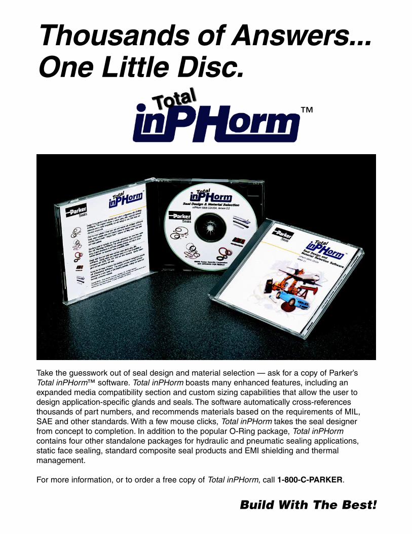
Thousands of Answers...One Little Disc.
Build With The Best!
Take the guesswork out of seal design and material selection — ask for a copy of Parker’sTotal inPHorm™ software. Total inPHorm boasts many enhanced features, including anexpanded media compatibility section and custom sizing capabilities that allow the user todesign application-specific glands and seals. The software automatically cross-referencesthousands of part numbers, and recommends materials based on the requirements of MIL,SAE and other standards. With a few mouse clicks, Total inPHorm takes the seal designerfrom concept to completion. In addition to the popular O-Ring package, Total inPHormcontains four other standalone packages for hydraulic and pneumatic sealing applications,static face sealing, standard composite seal products and EMI shielding and thermalmanagement.
For more information, or to order a free copy of Total inPHorm, call 1-800-C-PARKER.
™

Build With The Best!
Seals
Parker Hannifin CorporationO-Ring Division2360 Palumbo DriveLexington, KY 40509Telephone (859) 269-2351Fax (859) 335-5128www.parker.com/o-ring


