4
PAROC ® DELIGN ™ INSTALLATION GUIDE PAROC ® -panel solutions September 2017

PAROC® delign™ inSTAllATiOn gUide
PAROC®-panel solutions
September 2017
1 3
4 5
6
10a
7
Ø 27 mm
9
10b
10c
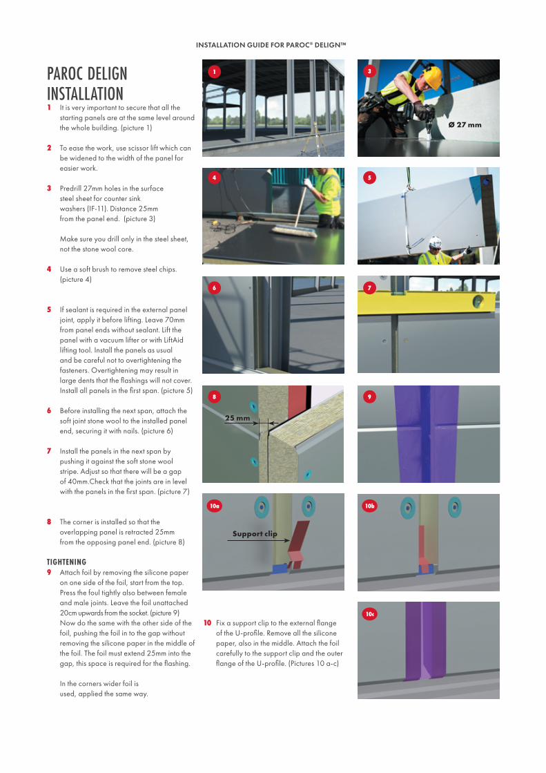
Paroc Delign installation1 It is very important to secure that all the
starting panels are at the same level around the whole building. (picture 1)
2 To ease the work, use scissor lift which can be widened to the width of the panel for easier work.
3 Predrill 27mm holes in the surface steel sheet for counter sink washers (IF-11). Distance 25mm from the panel end. (picture 3) Make sure you drill only in the steel sheet, not the stone wool core.
4 Use a soft brush to remove steel chips. (picture 4)
5 If sealant is required in the external panel joint, apply it before lifting. Leave 70mm from panel ends without sealant. Lift the panel with a vacuum lifter or with LiftAid lifting tool. Install the panels as usual and be careful not to overtightening the fasteners. Overtightening may result in large dents that the flashings will not cover. Install all panels in the first span. (picture 5)
6 Before installing the next span, attach the soft joint stone wool to the installed panel end, securing it with nails. (picture 6)
7 Install the panels in the next span by pushing it against the soft stone wool stripe. Adjust so that there will be a gap of 40mm.Check that the joints are in level with the panels in the first span. (picture 7)
8 The corner is installed so that the overlapping panel is retracted 25mm from the opposing panel end. (picture 8)
9 Attach foil by removing the silicone paper on one side of the foil, start from the top. Press the foul tightly also between female and male joints. Leave the foil unattached 20cm upwards from the socket. (picture 9) Now do the same with the other side of the foil, pushing the foil in to the gap without removing the silicone paper in the middle of the foil. The foil must extend 25mm into the gap, this space is required for the flashing. In the corners wider foil is used, applied the same way.
Support clip
8
25 mm
TigHTening
10 Fix a support clip to the external flange of the U-profile. Remove all the silicone paper, also in the middle. Attach the foil carefully to the support clip and the outer flange of the U-profile. (Pictures 10 a-c)
INSTALLATION GUIDE FOR PAROC® DELIGN™

11 12
13a
1413c
13b
15
Corner flashing Middle flashing
16a
16b17a
17b
17c
11 Install the pre-drilled bottom flashings with flat-headed screws (FS-31), 8 screws/ flashing. Place the bottom flashing in the middle of the panel height, 50mm from horizontal joint and in a straight vertical line.
12 Cut the foil in the horizontal joints. (only the parts that are glued to the surface, not the middle of the foil. (picture 12)
13 When bottom flashings are installed, start the installation of the cover flashing from down and up. Push the upper end of the flashing into to the panel joint, twist the flashing downwards and press it so hard that it is locked into the bottom flashing. Ensure the locking of the flashing by hitting gently with a hammer and protecting piece of wooden board. The protecting piece has to be clean and as wide as the flashing. (pictures 13 a-c)
14 Ensure even the locking of the joint of the flashing. Hit gently with hammer and protecting piece so that the joint of the flashing locks over the female joint of the panel. (picture 14)
15 If the cover flashing is cut or not possible to lock into a panel joint, the cover flashing has to fastened, i.e at eaves and below windows. The upper end of the flashing must be fastened with a pop rivet to the panel. (picture 15)
16 Use laser equipment to mark a straight vertical line when installing corner flashings. Start installation from the bottom panel. Start with the overlapping panel and push the upper end of the flashing into the female joint. Twist the flashing downwards and steer the other side of the flashing into the female joint of the opposing panel. Fix the flashing with 4 srews on each side. (pictures 16 a-b)
17 Push the right cover flashing in between the panel joints. Slide it towards the middle part flashing. Lock the flashing with a pop rivet in the joint. Do the same with the left cover flashing. (pictures 17 a-c)
inSTAllATiOn OF FlASHingS
INSTALLATION GUIDE FOR PAROC® DELIGN™
1 2
3 4
PAROC PANEL SYSTEM OY ABFI-21600 Parainen, FinlandTel: +358 (0)46 876 8000e-mail [email protected]
The information in this data sheet describes the conditions and technical properties of the disclosed products, valid at the time of publication of this document and until replaced by the next printed or digital version. The latest version of this data sheet is always available on the Paroc website. Our information material presents applications for which the functions and technical properties of our products have been approved. However, the information does not mean a commercial guarantee. We do not assume liability of the use of third party components used in the application or the installation of our products. We cannot warrant the suitability of our products if used in an area or conditions which are not provided in our information material.
4 The top end of the cover flashing is fastened with pop rivet if it not locked into a panel joint.
CHeCKliST
1 The tightening foil gives sufficient space for the bottom flashing and the foil is attached firmly to the U-profiles outer flange.
2 The bottom flashing is fixed 8 screws with flat heads
3 The cover flashing is firmly tightened to the bottom flashing and there is no visible space between the flashing and the panel surface.
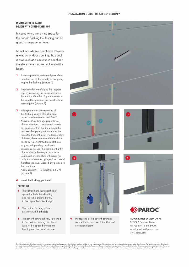
inSTAllATiOn OF PAROC delign WiTH glUed FlASHingS
In cases where there is no space for the bottom flashing the flashing can be glued to the panel surface.
Sometimes when a panel ends towards a window or door opening, the panel is produced as a continuous panel and therefore there is no vertical joint at the beam.
1 Fix a support clip to the mail joint of the panel on top of the panel you are going to glue the flashing. (picture 1)
2 Attach the foil carefully to the support clip, by removing the paper silicone in the middle of the foil. Tighten also over the panel fasteners on the panel with no vertical joint. (picture 2)
3 Wipe panel on coverage area of the flashing using a clean lint-free paper towel moistened with Sika® Aktivator-205. Change paper towel after each wipe. If pre-treated area is not bonded within the first 2 hours the process of applying activator must be repeated (max 2 times). The temperature of the air, the activator and the surface has to be +5…+4 0°C. Flash-off times may vary depending on climatic conditions. Re-seal the container tightly after each use. Prolonged exposure to atmospheric moisture will cause the activator to become opaque/cloudy and therefore inactive. Discard any product in this condition. Apply sealant TT-18 (Sikaflex-52 UV) (picture 3)
4 Install the flashing (picture 4)
INSTALLATION GUIDE FOR PAROC® DELIGN™


