151.15–1 Tank types.151.15–3 Construction.151.15–5 Venting.151.15–6 Venting piping.151.15–10 Cargo gauging devices.
Subpart 151.20—Cargo Transfer
151.20–1 Piping—general.151.20–5 Cargo system valving requirements.151.20–10 Cargo system instrumentation.151.20–15 Cargo hose if carried on the barge.151.20–20 Cargo transfer methods.
151.45–1 General.151.45–2 Special operating requirements.151.45–3 Manning.151.45–4 Cargo-handling.151.45–5 Open hopper barges.151.45–6 Maximum amount of cargo.151.45–7 Shipping papers.151.45–8 Illness, alcohol, drugs.151.45–9 Signals.
This part applies to the following:(a) Oceangoing, as defined in 33 CFR
151.05(j), non-self-propelled UnitedStates ships and non-self-propelled for-eign ships operating in United Stateswaters that carry a bulk cargo thatis—
(1) Listed in Table 151.05;(2) Not being carried in a portable
tank regulated under subpart 98.30 or98.33 of this chapter; and
(3) Not an NLS or is an NLS cargothat is a Category D listed in § 151.12–5of this part.
(b) All non-self-propelled UnitedStates ships that are not oceangoingthat carry a bulk cargo that is—
(1) Listed in Table 151.05, and(2) Not being carried in a portable
tank regulated under subpart 98.30 or98.33 of this chapter.
[CGD 81–101, 52 FR 7776, Mar. 12, 1987, asamended by CGD 84–043, 55 FR 37413, Sept. 11,1990]
§ 151.01–2 Incorporation by reference.
(a) Certain standards and specifica-tions are incorporated by referenceinto this part with the approval of theDirector of the Federal Register in ac-cordance with 5 U.S.C. 552(a). To en-force any edition other than the oneslisted in paragraph (b) of this section,notice of change must be published inthe FEDERAL REGISTER and the mate-rial made available to the public. Allapproved material is on file at the Of-fice of the Federal Register, 800 NorthCapitol Street, NW., suite 700, Wash-ington, DC, and is available from thesources indicated in paragraph (b) ofthis section.
VerDate 27-NOV-96 11:25 Dec 17, 1996 Jkt 167177 PO 00000 Frm 00056 Fmt 8010 Sfmt 8010 E:\CFR\167177.014 167177
57
Coast Guard, DOT § 151.01–15
(b) The standards and specificationsapproved for incorporation by ref-erence in this part and the sections af-fected, are:
ASNT ‘‘Recommended Practice No.SNT–TC–1A (1988), Personnel Qual-ification and Certification in Non-destructive Testing’’ .............151.04–7(c)(2)
American Society of Mechanical Engineers
United Engineering Center, 345 East 47thStreet, New York, NY 10017
ASME Boiler and Pressure VesselCode Section V, NondestructiveExamination (1986) ................151.04–7(a)(1)
[CGD 85–061, 54 FR 50965, Dec. 11, 1989]
§ 151.01–3 [Reserved]
§ 151.01–5 [Reserved]
§ 151.01–10 Application of vessel in-spection regulations.
(a) The regulations in this part arerequirements which may be in additionto, supplement, or modify require-ments in other subchapters in thischapter. When a specific requirementin another part or section in anothersubchapter in this chapter is in conflictwith or contrary to requirement or in-tent expressed in this part, the regula-tions in this part shall take prece-dence.
(b) Every unmanned tank bargewhich carries or is intended to carry inbulk any liquid or liquefied gas listedin Table 151.05 and has flammability orcombustibility characteristics as indi-cated by a fire protection requirementin Table 151.05 shall be inspected andcertificated under the provisions insubchapter D (Tank Vessels) of thischapter and the regulations in thispart.
(c) Every unmanned tank barge priorto the carriage in bulk of any liquid orliquefied gas listed in Table 151.05which does not have the flammabilityor combustibility characteristics as in-dicated by the fire protection require-ment in Table 151.05 shall be inspectedand certificated under the applicableprovisions of subchapter D or sub-chapter I of this chapter, at the optionof the barge owner, in addition to the
regulations in this part. However, un-less the barge owner notifies the Offi-cer in Charge, Marine Inspection of hisoption to have the barge inspected andcertificated under subchapter I at thetime he submits the application for in-spection (Form CG–3752), the un-manned tank barge shall be inspectedand certificated under the provisions ofsubchapter D of this chapter and theregulations in this part.
(c–1) Each unmanned tank barge con-structed on or after September 6, 1977,that carries in bulk a cargo listed inTable 151.05 and that is certificatedunder subchapter I of this chaptermust meet the loading information re-quirements in § 31.10–32 of this chapter.
(d) The provisions of subchapter D ofthis chapter shall apply to all un-manned tank barges which carry inbulk any of the liquids or liquefiedgases listed in Table 30.25–1 of thischapter. The provisions of this partshall not apply to such barges unless itis also desired to carry one or more ofthe liquids or liquefied gases listed inTable 151.05.
(e) Manned barges which carry or in-tend to carry in bulk the cargoes speci-fied in Table 151.05 will be consideredindividually by the Commandant andmay be required to meet the require-ments of this subchapter and of sub-chapter D (Tank Vessels) or I (Cargoand Miscellaneous Vessels) of thischapter as applicable.
[CGFR 70–10, 35 FR 3714, Feb. 25, 1970]
EDITORIAL NOTE: For Federal Register cita-tions affecting § 151.01–10, see the List of CFRSections Affected in the Finding Aids sec-tion of this volume.
§ 151.01–15 Dangerous cargoes not spe-cifically named.
(a) Any liquid or liquefied gas, whichmeets the definitions referred to in§ 151.01–1 and is not named in Table151.05 or Table 30.25–1 of this chaptershall not be transported in bulk in amanned or unmanned tank barge with-out the prior specific approval of theCommandant.
(b) Mixtures or blends of two or morecargoes, one or more of which appearsin Table 151.05, will be treated asthough they were new products andspecific approval of the Commandant
VerDate 27-NOV-96 11:25 Dec 17, 1996 Jkt 167177 PO 00000 Frm 00057 Fmt 8010 Sfmt 8010 E:\CFR\167177.014 167177
58
46 CFR Ch. I (10–1–96 Edition)§ 151.01–20
must be obtained prior to undertakingtheir transportation.
[CGFR–70–10, 35 FR 3714, Feb. 25, 1970, asamended by CGD 81–101, 52 FR 7777, Mar. 12,1987; CGD 81–101, 53 FR 28974, Aug. 1, 1988 and54 FR 12629, Mar. 28, 1989; CGD 88–100, 54 FR40029, Sept. 29, 1989]
§ 151.01–20 Use of minimum require-ments.
(a) The minimum requirements gov-erning transportation of any liquid orliquefied gas listed in Table 151.05 areset forth in this part when such sub-stances are carried in bulk in un-manned tank barges.
(b) Before any liquid or liquefied gaslisted in Table 151.05 may be carried inan unmanned tank barge, the certifi-cate of inspection issued to such bargeshall be appropriately endorsed to showapproval to transport such cargo.
(a) Except as provided in paragraph(c) of this section, barges certified for,or used within the previous 2 yearsprior to the effective date of this regu-lation, or barges equivalent to suchbarges, for the transportation of anycargo regulated by this subchapterwhich do not meet the specific require-ments herein, may be continued inservice subject to the following condi-tions:
(1) Venting, gauging, and all operat-ing requirements shall be met within a1–year period subsequent to the effec-tive date.
(2) All other requirements shall bemet within a 2–year period subsequentto the effective date.
(b) If an existing barge, which hasbeen designed to carry or has regularlybeen carrying one or more of the car-goes regulated by this subchapter, isfound to be so arranged, or outfittedthat conversion to bring it into compli-ance with any or all of the require-ments of this subchapter is impracticalor impossible, the Commandant, uponapplication, may review the plans ofthe barge to determine if it is suitableand safe for the cargoes to be trans-ported.
(c) Except for operating and vinylchloride requirements, barges con-structed and certificated for the trans-portation of any cargo for which spe-cific regulations existed, in parts 36, 38,39, 40, and 98 of this chapter at the timeof their construction or conversion,may continue and will be certificatedto operate without the requirementthat they comply with the provisionsof subchapter O of this chapter.
§ 151.01–30 Effective date.(a) The regulations in this sub-
chapter are effective on and after June1, 1970. However, amendments, revi-sions, or additions shall become effec-tive ninety (90) days after the date ofpublication in the FEDERAL REGISTERunless the Commandant shall fix a dif-ferent time.
(b) The regulations in this sub-chapter are not retroactive in effectunless specifically made so at the timethe regulations are issued. Changes inspecification requirements of articlesof equipment, or materials used in con-struction of tank barges, shall notapply to such items which have beenpassed as satisfactory until replace-ment shall become necessary, unless aspecific finding is made that suchequipment or materials used is unsafeor hazardous and has to be removedfrom tank barges.
§ 151.01–35 Right of appeal.Any person directly affected by a de-
cision or action taken under this part,by or on behalf of the Coast Guard,may appeal therefrom in accordancewith subpart 1.03 of this chapter.
[CGD 88–033, 54 FR 50381, Dec. 6, 1989]
Subpart 151.02—Equivalents§ 151.02–1 Conditions under which
equivalents may be used.(a) Where in this part it is provided
that a particular fitting, material, ap-pliance, apparatus, or equipment, ortype thereof, shall be fitted or carriedin a vessel, or that any particular pro-vision shall be made or arrangementincluding cargo segregation shall be
VerDate 27-NOV-96 11:25 Dec 17, 1996 Jkt 167177 PO 00000 Frm 00058 Fmt 8010 Sfmt 8010 E:\CFR\167177.014 167177
59
Coast Guard, DOT § 151.03–23
adopted, the Commandant may acceptin substitution therefor any other fit-ting, material, apparatus or equip-ment, or type thereof, or any otherprovision or arrangement. However,the Commandant shall be satisfied bysuitable evidence that the fitting, ma-terial, appliance, apparatus, or equip-ment, or the type thereof, or the provi-sion or arrangement shall be at least aseffective as that specified in this part.
(b) In any case where it is shown tothe satisfaction of the Commandantthat the use of any particular equip-ment, apparatus, or arrangement notspecifically required by law is unrea-sonable or impracticable, the Com-mandant may permit the use of alter-nate equipment apparatus, or arrange-ment to such an extent and upon suchconditions as will insure, to his satis-faction, a degree of safety consistentwith the minimum standards set forthin this part.
§ 151.02–5 Design of unmanned barges.
(a) In order not to inhibit design andapplication, the Commandant may ap-prove vessels of novel design, both newand for conversion, after it is shown tohis satisfaction that such a vessel is atleast as safe as any vessel which meetsthe standards required by this part.
(b) [Reserved]
Subpart 151.03—Definitions
§ 151.03–1 Definitions of terms.
Certain terms used in the regulationsin this subchapter are defined in thissubpart.
§ 151.03–3 Angle of downflooding.
The angle of heel of the vessel atwhich any opening in the hull not pro-vided with a water tight closure wouldbe immersed.
§ 151.03–5 Approved.
This term means approved by theCommandant unless otherwise stated.
§ 151.03–7 Barge.
This term means any non-self-pro-pelled vessel designed to carry cargo.
§ 151.03–9 Cargo.
This term means any liquid, gas orsolid having one or more of the dan-gerous properties defined in this sub-chapter.
§ 151.03–11 Coastwise.
This designation refers to all vesselsnormally navigating the waters of anyocean or the Gulf of Mexico 20 nauticalmiles or less offshore.
§ 151.03–13 Cofferdam.
This term means a void or emptyspace separating two or more compart-ments for the purpose of isolation or toprevent the contents of one compart-ment from entering another in theevent of the failure of the walls of oneto retain their tightness.
§ 151.03–15 Commandant.
This term means Commandant of theU.S. Coast Guard.
§ 151.03–17 Compatible.
Compatible means that a cargo willnot react in an unsafe manner withother cargo or materials used in con-struction of the barge. The prime con-siderations are the chemical, physical,or thermal properties of the reactionincluding heat, pressure, toxicity, sta-bility, and explosive nature of the reac-tion and its end products.
§ 151.03–19 Environment.
This term refers to the atmospherewithin a cargo tank and the spaces ad-jacent to the tank or spaces in whichcargo is handled.
§ 151.03–21 Filling density.
The ratio, expressed as a percentage,of the weight of cargo that may beloaded into a tank compared to theweight of water that the tank will holdat 60°F. The weight of a gallon of waterat 60°F. in air shall be 8.32828 pounds.
§ 151.03–23 Flame arrestor.
Any device or assembly of cellular,tubular, pressure or other type used forpreventing the passage of flames intoenclosed spaces.
VerDate 27-NOV-96 11:25 Dec 17, 1996 Jkt 167177 PO 00000 Frm 00059 Fmt 8010 Sfmt 8010 E:\CFR\167177.015 167177
60
46 CFR Ch. I (10–1–96 Edition)§ 151.03–25
§ 151.03–25 Flame screen.A fitted single screen of corrosion-re-
sistant wire of at least 30 by 30 mesh ortwo fitted screens, both of corrosion-re-sistant wire, of at least 20 by 20 meshspaced not less than one-half inch ormore than 11⁄2 inches apart.
§ 151.03–27 Gas free.Free from dangerous concentrations
of flammable or toxic gases.
§ 151.03–29 Great Lakes.A designation for all vessels in Great
Lakes service.
§ 151.03–30 Hazardous material.In this part hazardous material means
a liquid material or substance that is—(a) Flammable or combustible;(b) Designated a hazardous substance
under section 311(b) of the FederalWater Pollution Control Act (33 U.S.C.1321); or
(c) Designated a hazardous materialunder section 104 of the Hazardous Ma-terial Transportation Act (HMTA) (49U.S.C. 1803).
NOTE: The Environmental ProtectionAgency designates hazardous substances in40 CFR Table 116.4A. The Coast Guard des-ignates hazardous materials that are trans-ported as bulk liquids by water in § 153.40.
[CGD 81–101, 52 FR 7777, Mar. 12, 1987]
§ 151.03–31 Headquarters.The Office of the Commandant, U.S.
§ 151.03–33 Lakes, bays, and sounds.A designation for all vessels navigat-
ing the waters of any of the lakes,bays, or sounds other than the watersof the Great Lakes.
§ 151.03–35 Limiting draft.Maximum allowable draft to which a
barge may be loaded. Limiting draft isa function of hull type and cargo spe-cific gravity. A barge may be assigneddifferent limiting drafts for differenthull types or within one hull type fordifferent specific gravities.
§ 151.03–36 Liquid.In this part liquid includes liquefied
and compressed gases.
[CGD 81–101, 52 FR 7777, Mar. 12, 1987]
§ 151.03–37 Maximum allowable work-ing pressure.
The maximum allowable workingpressure shall be as defined in sectionVIII of the ASME Boiler and PressureVessel Code.[CGFR 70–10, 35 FR 3714, Feb. 25, 1970, asamended by CGD 85–061, 54 FR 50965, Dec. 11,1989]
§ 151.03–38 Nondestructive testing.Nondestructive testing includes ul-
trasonic examination, liquid penetrantexamination, magnetic particle exam-ination, radiographic examination,eddy current, and acoustic emission.
[CGD 85–061, 54 FR 50965, Dec. 11, 1989]
§ 151.03–39 Ocean.A designation for all vessels nor-
mally navigating the waters of anyocean or the Gulf of Mexico more than20 nautical miles offshore.
§ 151.03–41 Officer in Charge, MarineInspection.
Any person from the civilian or mili-tary branch of the Coast Guard des-ignated as such by the Commandantand who, under the superintendenceand direction of the Coast Guard Dis-trict Commander, is in charge of an in-spection zone for the performance ofduties with respect to the enforcementand administration of title 52 R.S., actsamendatory thereof or supplementalthereto, and rules and regulationsthereunder.
§ 151.03–43 Pressure.Terminology used in this part are:
pounds per square inch gauge (p.s.i.g.)or pounds per square inch absolute(p.s.i.a.). 14.7 p.s.i.a. is equal to 0p.s.i.g. P.s.i.g. is normally used in ref-erence to design or operating require-ments.
§ 151.03–45 Rivers.A designation for all vessels whose
navigation is restricted to rivers and/orcanals, exclusively.
VerDate 27-NOV-96 11:25 Dec 17, 1996 Jkt 167177 PO 00000 Frm 00060 Fmt 8010 Sfmt 8010 E:\CFR\167177.015 167177
61
Coast Guard, DOT § 151.04–5
§ 151.03–47 Service.The waters upon which a vessel may
be operated as endorsed upon the cer-tificate of inspection.
§ 151.03–49 Sounding tube.This is an unperforated tube fitted to
an ullage hole, secured so as to bevapor tight to the underside of thetank top open at the bottom, and ex-tending to within 18 inches or less ofthe bottom of the tank.
§ 151.03–51 Tank barge.A non-self-propelled vessel especially
constructed or converted to carry bulkliquid cargo in tanks.
§ 151.03–53 Tankerman.The following ratings are established
in part 13 of this chapter. The terms forthe ratings identify persons holdingvalid merchant mariners’ documentsfor service in the ratings issued underthat part:
§ 151.04–1 Certificate of inspection.(a) A certificate of inspection is re-
quired for every unmanned tank bargesubject to the requirements in this sub-chapter. A certificate of inspectionshall be issued to the barge or to itsowners by the Officer in Charge, Ma-rine Inspection, if the barge is found tocomply with applicable inspection lawsand the regulations in this chapter.
(b) The certificate of inspection shallbe endorsed with respect to the watersover which the barge may be operated.
(c) The certificate shall be endorseddescribing the cargoes by name asgiven in Table 151.05 or as specificallyapproved by the Commandant. Noother dangerous cargo as defined inSubpart 151.01–1 shall be carried. Cer-
tificates shall specify maximum cargoweight (short tons), maximum density(pounds per gallon) and any operatinglimitations and a limiting draft.
§ 151.04–2 Inspection required.(a) Every unmanned tank barge sub-
ject to the regulations in this sub-chapter shall be inspected biennially.More frequent inspections may be re-quired, if necessary, by the Officer inCharge, Marine Inspection, to see thatthe hull, equipment and appliances ofthe vessel comply with the marine in-spection laws, and the regulations ofthis subchapter and other subchapterswhere applicable.
(b) [Reserved]
§ 151.04–3 Initial inspection.(a) The initial inspection which may
consist of a series of inspections duringthe construction of an unmanned bargeshall include a complete inspection ofthe structure, auxiliary machinery,and equipment. The inspection shall besuch as to insure that the arrange-ment, materials, and scantlings of thehull structure, tanks and pressure ves-sels and their appurtenances complywith applicable regulations of thischapter and with the requirements ofthis part.
(b) [Reserved]
§ 151.04–5 Inspection for certification.(a) An inspection for certification is
a prerequisite of the reissuance of aCertificate of Inspection as providedfor in applicable regulations of thischapter.
(b) Unless otherwise specified intable 151.05, cargo tanks are internallyexamined as follows:
(1) Where the cargo tank is of thegravity type and the structural fram-ing is on the internal tank surface, thetank shall be inspected internally atthe time of inspection for certification.
(2) Where the cargo tank is of thegravity type and the structural fram-ing is on the external tank surface ac-cessible for examination from voids,cofferdams, double bottoms, and othersimilar spaces, tanks shall be inspectedinternally at 4–year intervals.
VerDate 27-NOV-96 11:25 Dec 17, 1996 Jkt 167177 PO 00000 Frm 00061 Fmt 8010 Sfmt 8010 E:\CFR\167177.016 167177
62
46 CFR Ch. I (10–1–96 Edition)§ 151.04–5
(3) If the tank is a pressure-vesseltype cargo tank, an internal inspectionof the tank is conducted within—
(i) Ten years after the last internalinspection on an unmanned barge car-rying cargo at temperatures of ¥67 °F(¥55 °C) or warmer; or
(ii) Eight years after the last internalinspection if the tank is a pressuretype cargo tank carrying cargo at tem-peratures colder than ¥67 °F (¥55 °C).
(4) Internal inspection may be re-quired at more frequent intervals asdeemed necessary by the Officer inCharge, Marine Inspection.
(c) An external examination ofunlagged tanks and the visible parts oflagged tanks is made at each biennialinspection. If the vessel has single skinconstruction, the underwater portionof the tank need not be examined un-less deemed necessary by the Officer inCharge, Marine Inspection. If an exter-nal examination of the tank is not pos-sible because of insulation, the ownershall ensure that—
(1) The amount of insulation deemednecessary by the marine inspector isremoved during each cargo tank inter-nal inspection to allow spot externalexamination of the tanks and insula-tion; or
(2) The thickness of the tanks isgauged by a nondestructive means ac-cepted by the marine inspector withoutthe removal of insulation.
(d) If required by the Officer inCharge, Marine Inspection the ownershall conduct nondestructive testing ofeach tank designated by the Officer inCharge, Marine Inspection in accord-ance with § 151.04–7.
(e) If the Officer in Charge, MarineInspection considers a hydrostatic testnecessary to determine the conditionof the tanks, the owner shall performthe test at a pressure of 11⁄2 times thetank’s—
(1) Maximum allowable pressure, asdetermined by the safety relief valvesetting; or
(2) Design pressure, when cargo tanksoperate at maximum allowable pres-sures reduced below the design pressurein order to satisfy special mechanicalstress relief requirements.
NOTE: See the ASME Code, Section VIII,Appendix 3 for information on design pres-sure.
(f) Quick closing valves shall be test-ed by operating the emergency shutoffsystem from each operating point atthe time of each vessel’s inspection forcertification.
(g) Excess flow valves shall be in-spected at the time of inspection forcertification. The Officer in Charge,Marine Inspection, shall satisfy him-self that the valve is in working condi-tion by visual inspection, and if this isimpossible, by one of the followingmeans:
(1) Removing the valve and benchtesting ashore; the valve shall close ator below its rated closing flow.
(2) By any other means acceptable tothe Officer in Charge, Marine Inspec-tion, which will demonstrate that thevalve is operable.
(h) Pressure vaccum relief valvesshall be examined to determine thatthe operating mechanism is free andcapable of activation.
(i) Safety relief valves shall be testedby bench testing or other suitablemeans. The valves shall relieve andreseat within the design tolerances ofthe set pressure, or it shall be removedand reset prior to being returned toservice. This test shall be conducted atthe time of the inspection for certifi-cation.
(j) Cargo hose stored on board thevessel which is used in transferringcargoes listed in Table 151.05 shall beinspected every 2 years. This inspec-tion shall consist of a visual examina-tion and a hydrostatic test of 11⁄2 timesthe maximum pressure to which thehose will be subjected in service. Thedate of the most recent inspection andthe test pressure shall be stenciled orotherwise marked on the hose.
(k) Cargo piping shall be inspectedand tested at the same time as thecargo tanks.
(l) If the tank is a pressure vesseltype cargo tank with an internal in-spection interval of 10 years, and is 30years old or older, determined from thedate it was built, the owner shall con-duct nondestructive testing of eachtank in accordance with § 151.04–7, dur-ing each internal inspection.
VerDate 27-NOV-96 11:25 Dec 17, 1996 Jkt 167177 PO 00000 Frm 00062 Fmt 8010 Sfmt 8010 E:\CFR\167177.016 167177
63
Coast Guard, DOT § 151.05–1
§ 151.04–7 Nondestructive testing.(a) Before nondestructive testing
may be conducted to meet § 151.04–5 (d)and (l), the owner shall submit a pro-posal to the Officer in Charge, MarineInspection that includes—
(1) The test methods and proceduresto be used all of which must meet sec-tion V of the ASME Boiler and Pres-sure Vessel Code (1986);
(2) Each location on the tank to betested; and
(3) The test method and procedure tobe conducted at each location on thetank.
(b) If the Officer in Charge, MarineInspection rejects the proposal, the Of-ficer in Charge, Marine Inspection in-forms the owner of the reasons why theproposal is rejected.
(c) If the Officer in Charge, MarineInspection accepts the proposal, thenthe owner shall ensure that—
(1) The proposal is followed; and(2) Nondestructive testing is per-
formed by personnel meeting ASNT‘‘Recommended Practice No. SNT–TC–1A (1988), Personnel Qualification andCertification in Nondestructive Test-ing.’’
(d) Within 30 days after completingthe nondestructive test, the ownershall submit a written report of the re-sults to the Officer in Charge, MarineInspection.
[CGD 85–061, 54 FR 50966, Dec. 11, 1989]
Subpart 151.05—Summary of Mini-mum Requirements for Spe-cific Cargoes
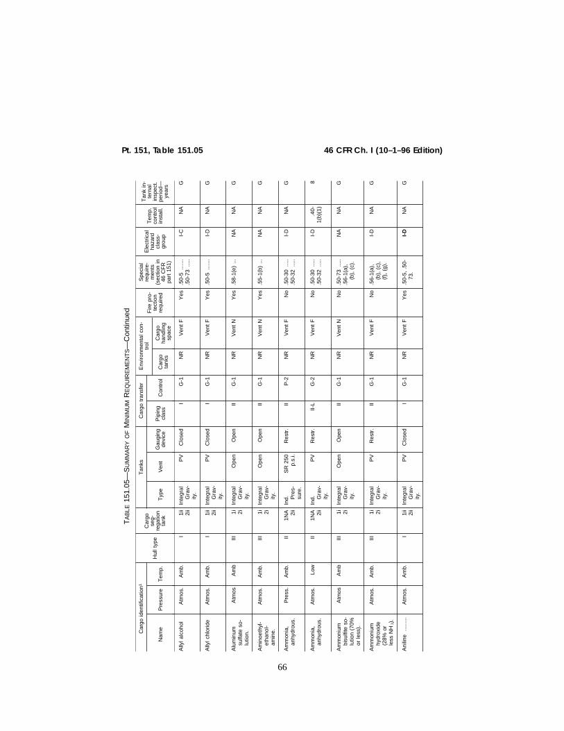
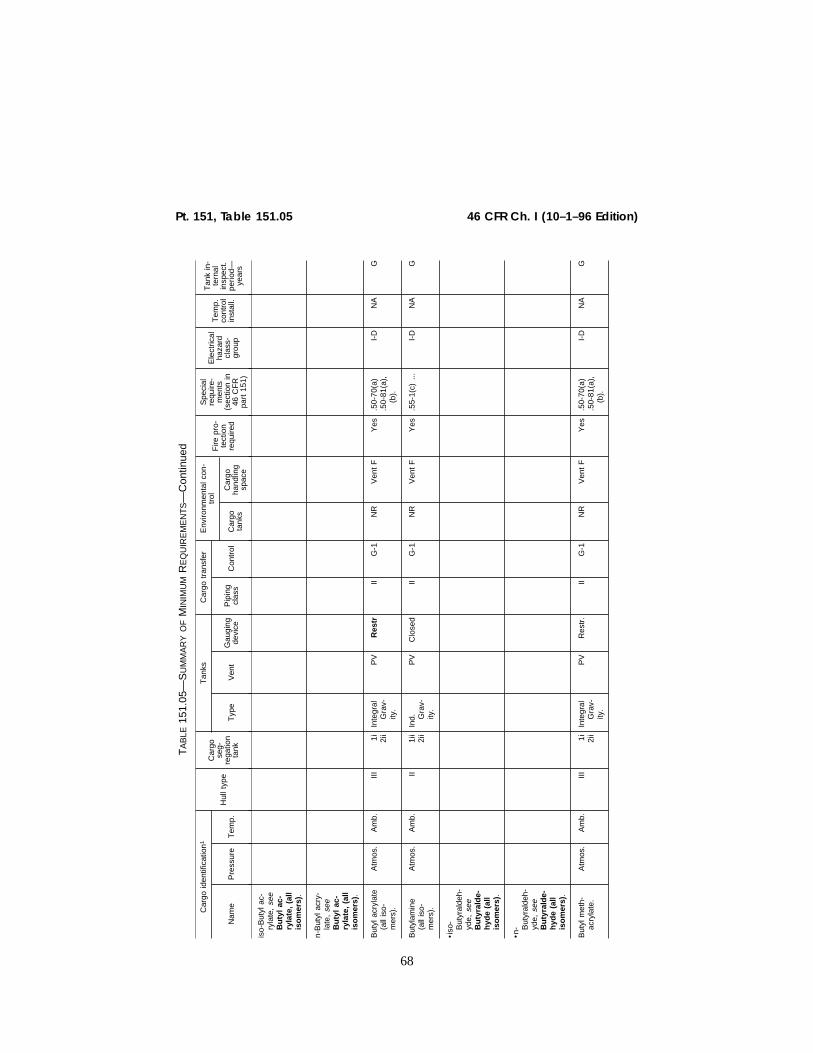
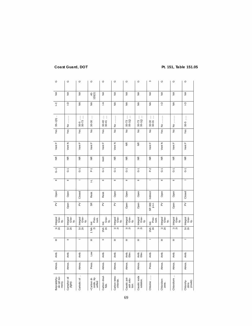
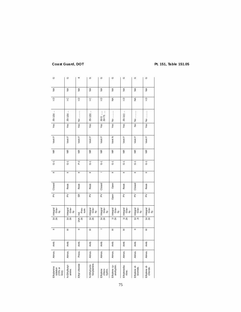
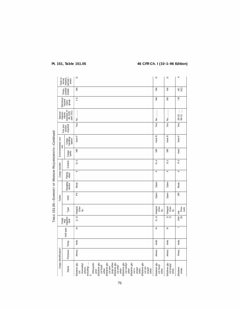
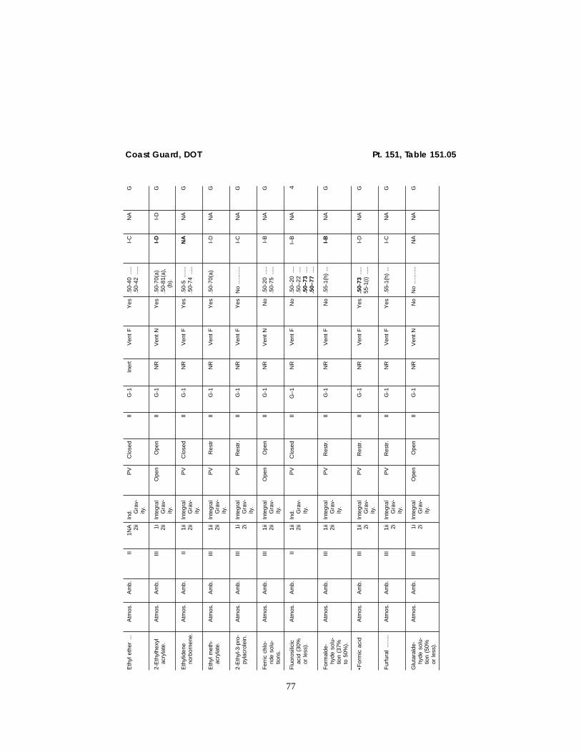
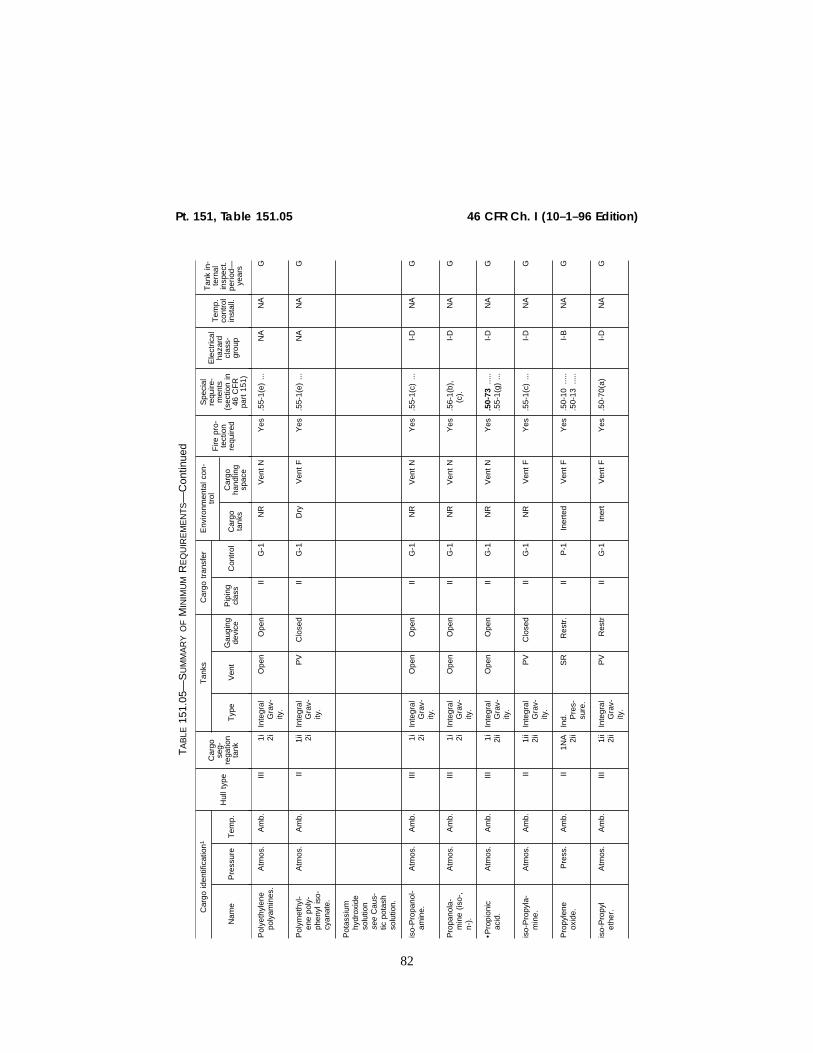
§ 151.05–1 Explanation of column head-ings in Table 151.05.
(a) Cargo identification/name. This col-umn identifies cargoes by name. Wordsin italics are not part of the cargoname but may be used in addition tothe cargo name. When one entry ref-erences another entry by use of theword ‘‘see’’ and both names are inroman type, either name may be usedas the cargo name (e.g., ‘‘Diethyl ei-ther see Ethyl ether’’). However, thereferenced entry is preferred.
(b) Cargo identification/pressure. Thiscolumn identifies cargo in terms ofpressure within the tank. Terms usedare:
(1) Pressurized. Cargo carried at apressure in excess of 10 pounds persquare inch gauge as measured at thetop of the tank (i.e., exclusive of statichead).
(2) Atmospheric pressure. Cargo carriedat not more than 10 pounds per squareinch gauge, exclusive of static head.
(c) Cargo identification/temperature.This column identifies the cargo by thetemperature of the cargo during tran-sit.
(1) Ambient temperature. Cargo whichis carried at naturally occurring tem-peratures.
(2) Low temperature. Cargo carriedbelow ambient temperatures when theproduct temperature is below 0°F.
(d) Hull type. This column refers tothe flotation features of the barge.Terms used are explained and definedin Subpart 151.10 of this part.
(e) Cargo segregation/tanks. This col-umn refers to the separation of thecargo from its surroundings. Terms areexplained in § 151.13–5 and in footnotesto Table 151.05 of this part.
(f) [Reserved](g) Tanks/type. This column refers to
the design requirements for cargotanks and their placement within thehull of the vessel. Terms are explainedin § 151.15–1.
(h) Tanks/venting. This column refersto arrangements for preventing excesspressure or vacuum within the cargotank. Terms used are explained and de-fined in § 151.15–5.
(i) Tanks/gauging devices. This columnrefers to arrangements provided for de-termining the amount of cargo presentin cargo tanks. Terms used are ex-plained and defined in § 151.15–10.
(j) Cargo transfer/piping. This columnrefers to the classification of piping inaccordance with Subchapter F of thischapter as discussed in § 151.20–1.
(k) Cargo transfer/control. This col-umn refers to the valving requirementsfor the cargo piping system. These re-quirements are defined in § 151.20–5.
(l) Environmental control/cargo tanks.This column refers to control of thecomposition of the environment withincargo tanks. Definitions and detailedrequirements are given in § 151.25–1.
VerDate 27-NOV-96 11:25 Dec 17, 1996 Jkt 167177 PO 00000 Frm 00063 Fmt 8010 Sfmt 8010 E:\CFR\167177.016 167177
64
46 CFR Ch. I (10–1–96 Edition)§ 151.05–2
(m) Environmental control/cargo han-dling space. This column refers to con-trol of the environment in the cargohandling spaces. Definitions and de-tailed requirements are found in§ 151.25–2.
(n) Fire protection. This column speci-fies whether portable fire extinguishersare required on barges carrying thecargo named. Requirements for cargoesrequiring extinguishers are given inSubpart 151.30 of this part.
(o) Special requirements. This columnrefers to requirements in subparts151.40, 151.50, 151.55, 151.56, and 151.58 ofthis part which apply to specific car-goes. The section numbers listed omitthe preceding part designation, ‘‘151’’.
(p) Electrical hazard class—group. Thiscolumn lists the electrical hazard classand group used for the cargo when de-termining requirements for electricalequipment under subchapter J (Elec-trical engineering) of this chapter.
(q) Temperature control installations.This column refers to systems whichare used to control the temperature ofthe cargo. Definitions and require-ments which are applicable if such sys-tems are used are given in Subpart151.40 of this part.
(r) Tank inspection period. This col-umn refers to the maximum period in
years between internal cargo tank in-spections. Applicable requirements aregiven in § 151.04–5.
§ 151.05–2 Compliance with require-ments for tank barges carrying ben-zene and benzene containing car-goes, or butyl acrylate cargoes.
A tank barge certificated to carrybenzene and benzene containing car-goes or butyl acrylate cargoes mustcomply with the gauging requirementof Table 151.05 of this part by August15, 1998. Until that date, a tank bargecertificated to carry benzene and ben-zene containing cargoes must meet ei-ther the gauging requirement of Table151.05 or the restricted or closed gaug-ing requirements in effect on Septem-ber 29, 1994; and a tank barge certifi-cated to carry butyl acrylate cargoesmust meet either the gauging require-ments of Table 151.05 or comply withthe open, restricted, or closed gaugingrequirements in effect on September29, 1994.
[CGD 95–900, 60 FR 34050, June 29, 1995]
VerDate 27-NOV-96 11:25 Dec 17, 1996 Jkt 167177 PO 00000 Frm 00064 Fmt 8010 Sfmt 8010 E:\CFR\167177.016 167177
65
Coast Guard, DOT Pt. 151, Table 151.05
TA
BLE
151.
05—
SU
MM
AR
YO
FM
INIM
UM
RE
QU
IRE
ME
NT
S
Car
go id
entif
icat
ion1
Hul
l typ
e
Car
gose
g-re
gatio
nta
nk
Tan
ksC
argo
tra
nsfe
rE
nviro
nmen
tal c
on-
trol
Fire
pro
-te
ctio
nre
quire
d
Spe
cial
requ
ire-
men
ts(s
ectio
n in
46 C
FR
part
151
)
Ele
ctric
alha
zard
clas
s-gr
oup
Tem
p.co
ntro
lin
stal
l.
Tan
k in
-te
rnal
insp
ect.
perio
d—ye
ars
Nam
eP
ress
ure
Tem
p.T
ype
Ven
tG
augi
ngde
vice
Pip
ing
clas
sC
ontr
olC
argo
tank
s
Car
goha
ndlin
gsp
ace
Ace
tald
ehyd
eP
ress
.A
mb.
II1N
A 2ii
Ind. P
res-
sure
.
SR
Res
tr.
IIP
-1In
erte
dV
ent
FY
es.5
5-1(
h)...
I-C
NA
G
•Ace
tic a
cid
Atm
os.
Am
b.III
1i 2ii
Inte
gral
Gra
v-ity
.
Ope
nO
pen
IIG
-1N
RV
ent
NY
es.5
0-73
.....
55-1
(g)D
I-D
.
NA
G
•Ace
tic a
nhy-
drid
e.A
tmos
.A
mb.
III1i 2i
iIn
tegr
alG
rav-
ity.
PV
Res
tr.
IIG
-1N
RV
ent
FY
es.5
0-73
.....
.55-
1(g)
...I-
DN
AG
Ace
tone
cya
-no
hydr
in.
Atm
os.
Am
b.I
1ii 2i
Inte
gral
Gra
v-ity
.
PV
Clo
sed
IG
-1N
RV
ent
FY
es.5
0-5
......
..5
0-70
(b)
.50-
73...
...5
0-81
.....
I-D
NA
G
Ace
toni
trile
...A
tmos
.A
mb.
III1i 2i
iIn
tegr
alG
rav-
ity.
PV
Res
tr.
IIG
-1N
RV
ent
FY
esN
o...
......
..I-
DN
AG
Acr
ylic
aci
d..
Atm
osA
mb
III1i
i2i
iIn
tegr
alG
rav-
ity.
PV
Res
tr.
IIG
-1N
RV
ent
FY
es.5
0-70
(a)
.50-
73...
...5
0-81
.....
.58-
1(a)
...
I-D
NA
G
Acr
ylon
itrile
..A
tmos
.A
mb.
II1i
i2i
iIn
tegr
alG
rav-
ity.
PV
Clo
sed
IIG
-1N
RV
ent
FY
es.5
5-1(
e)...
.50-
70(a
)I-
DN
AG
Adi
poni
trile
...A
tmos
.A
mb.
II1i
i 2iIn
tegr
alG
rav-
ity.
PV
Ope
nII
G-1
NR
Ven
t F
Yes
No
......
.....
I-D
NA
G
Alk
yl(C
7–C
9)ni
trat
es.
Atm
os.
Am
b.III
1i 2ii
Inte
gral
Gra
v-ity
.
Ope
nO
pen
IIG
–1N
RV
ent
NY
es.5
0–81
....
.50–
86...
.N
AN
AG
VerDate 27-NOV-96 11:25 Dec 17, 1996 Jkt 167177 PO 00000 Frm 00065 Fmt 8010 Sfmt 8010 E:\CFR\167177.016 167177
66
46 CFR Ch. I (10–1–96 Edition)Pt. 151, Table 151.05
TA
BLE
151.
05—
SU
MM
AR
YO
FM
INIM
UM
RE
QU
IRE
ME
NT
S—
Con
tinue
d
Car
go id
entif
icat
ion1
Hul
l typ
e
Car
gose
g-re
gatio
nta
nk
Tan
ksC
argo
tra
nsfe
rE
nviro
nmen
tal c
on-
trol
Fire
pro
-te
ctio
nre
quire
d
Spe
cial
requ
ire-
men
ts(s
ectio
n in
46 C
FR
part
151
)
Ele
ctric
alha
zard
clas
s-gr
oup
Tem
p.co
ntro
lin
stal
l.
Tan
k in
-te
rnal
insp
ect.
perio
d—ye
ars
Nam
eP
ress
ure
Tem
p.T
ype
Ven
tG
augi
ngde
vice
Pip
ing
clas
sC
ontr
olC
argo
tank
s
Car
goha
ndlin
gsp
ace
Ally
l alc
ohol
Atm
os.
Am
b.I
1ii
2ii
Inte
gral
Gra
v-ity
.
PV
Clo
sed
IG
-1N
RV
ent
FY
es.5
0-5
......
..5
0-73
.....
I-C
NA
G
Ally
l chl
orid
eA
tmos
.A
mb.
I1i
i2i
iIn
tegr
alG
rav-
ity.
PV
Clo
sed
IG
-1N
RV
ent
FY
es.5
0-5
......
.I-
DN
AG
Alu
min
umsu
lfate
so-
lutio
n.
Atm
osA
mb
III1i 2i
Inte
gral
Gra
v-ity
.
Ope
nO
pen
IIG
-1N
RV
ent
NY
es.5
8-1(
e)...
NA
NA
G
Am
inoe
thyl
-et
hano
l-am
ine.
Atm
os.
Am
b.III
1i 2iIn
tegr
alG
rav-
ity.
Ope
nO
pen
IIG
-1N
RV
ent
NY
es.5
5-1(
b)...
NA
NA
G
Am
mon
ia,
anhy
drou
s.P
ress
.A
mb.
II1N
A 2ii
Ind. P
res-
sure
.
SR
250
p.s.
i.R
estr
.II
P-2
NR
Ven
t F
No
.50-
30...
...5
0-32
.....
I-D
NA
G
Am
mon
ia,
anhy
drou
s.A
tmos
.Lo
wII
1NA 2ii
Ind. G
rav-
ity.
PV
Res
tr.
II-L
G-2
NR
Ven
t F
No
.50-
30...
...5
0-32
.....
I-D
.40-
1(b)
(1)
8
Am
mon
ium
bisu
lfite
so-
lutio
n (7
0%or
less
).
Atm
osA
mb
III1i 2i
Inte
gral
Gra
v-ity
.
Ope
nO
pen
IIG
-1N
RV
ent
NN
o.5
0-73
.....
.56-
1(a)
,(b
), (
c).
NA
NA
G
Am
mon
ium
hydr
oxid
e(2
8% o
rle
ss N
H3).
Atm
os.
Am
b.III
1i 2iIn
tegr
alG
rav-
ity.
PV
Res
tr.
IIG
-1N
RV
ent
FN
o.5
6-1(
a),
(b),
(c)
,(f
), (
g).
I-D
NA
G
Ani
line
......
...A
tmos
.A
mb.
I1i
i2i
iIn
tegr
alG
rav-
ity.
PV
Clo
sed
IG
-1N
RV
ent
FY
es.5
0-5,
.50
-73
.I-
DN
AG
VerDate 27-NOV-96 11:25 Dec 17, 1996 Jkt 167177 PO 00000 Frm 00066 Fmt 8010 Sfmt 8010 E:\CFR\167177.016 167177
67
Coast Guard, DOT Pt. 151, Table 151.05
Ant
hrac
ene
oil (
Coa
lta
r fr
actio
n).
Atm
os.
Am
b.E
lev.
II1i
i2i
iIn
tegr
alG
rav-
ity.
Ope
nO
pen
IIG
-1N
RV
ent
NY
esN
o...
......
..I-
DN
AG
Arg
on,
lique
-fie
d.P
ress
.Lo
wIII
1NA 2i
Ind. P
res-
sure
.
SR
Res
tr.
II-L
P-1
NR
Ven
t F
No
.40-
1(a)
....5
0-30
.....
.50-
36.
....
NA
.40-
1(a)
G
Ben
zene
......
Atm
os.
Am
b.III
1i 2ii
Inte
gral
Gra
v-ity
.
PV
Clo
sed
IIG
-1N
RV
ent
FY
es.5
0-60
.....
I-D
NA
G
Ben
zene
hy-
droc
arbo
nm
ixtu
res
(con
tain
ing
Ace
tyle
ne-
s) (
havi
ng10
% B
en-
zene
or
mor
e).
Atm
os.
Am
b.III
1i 2ii
Inte
gral
Gra
v-ity
.
PV
Clo
sed
IIG
-1N
RV
ent
FY
es.5
6-1(
b),
(d),
(f)
,(g
),.
I-D
NA
G
Ben
zene
hy-
droc
arbo
nm
ixtu
res
(hav
ing
10%
Ben
-ze
ne o
rm
ore)
.
Atm
os.
Am
b.III
1i 2ii
Inte
gral
Gra
v-ity
.
PV
Clo
sed
IIG
-1N
RV
ent
FY
es...
......
......
..I-
DN
AG
•Ben
zene
,T
olue
ne,
Xyl
ene
mix
ture
s(h
avin
g10
% B
en-
zene
or
mor
e).
Atm
os.
Am
b.III
1i 2ii
Inte
gral
Gra
v-ity
.
PV
Clo
sed
IIG
-1N
RV
ent
FY
esN
o...
......
..I-
DN
AG
But
adie
ne...
.P
ress
.A
mb.
II1N
A 2ii
Ind. P
res-
sure
.
SR
Res
tr.
IIP
-2N
RV
ent
FY
es.5
0-70
(a),
.50-
73.
I-B
NA
G
But
adie
ne,
But
ylen
em
ixtu
res
(con
tain
ing
Ace
tyle
ne-
s).
Pre
ss.
Am
b.II
1NA 2ii
Ind. P
res-
sure
.
SR
Res
tr.
IIP
-1N
RV
ent
FY
es.5
0-30
.....
.50-
70(a
),.5
0-73
..5
6-1(
b),
(d),
(f)
,(g
).
I-B
NA
G
VerDate 27-NOV-96 11:25 Dec 17, 1996 Jkt 167177 PO 00000 Frm 00067 Fmt 8010 Sfmt 8010 E:\CFR\167177.016 167177
68
46 CFR Ch. I (10–1–96 Edition)Pt. 151, Table 151.05
TA
BLE
151.
05—
SU
MM
AR
YO
FM
INIM
UM
RE
QU
IRE
ME
NT
S—
Con
tinue
d
Car
go id
entif
icat
ion1
Hul
l typ
e
Car
gose
g-re
gatio
nta
nk
Tan
ksC
argo
tra
nsfe
rE
nviro
nmen
tal c
on-
trol
Fire
pro
-te
ctio
nre
quire
d
Spe
cial
requ
ire-
men
ts(s
ectio
n in
46 C
FR
part
151
)
Ele
ctric
alha
zard
clas
s-gr
oup
Tem
p.co
ntro
lin
stal
l.
Tan
k in
-te
rnal
insp
ect.
perio
d—ye
ars
Nam
eP
ress
ure
Tem
p.T
ype
Ven
tG
augi
ngde
vice
Pip
ing
clas
sC
ontr
olC
argo
tank
s
Car
goha
ndlin
gsp
ace
iso-
But
yl a
c-ry
late
, se
eB
uty
l ac
-ry
late
, (a
llis
om
ers)
.
n-B
utyl
acr
y-la
te,
see
Bu
tyl
ac-
ryla
te,
(all
iso
mer
s).
But
yl a
cryl
ate
(all
iso-
mer
s).
Atm
os.
Am
b.III
1i 2ii
Inte
gral
Gra
v-ity
.
PV
Res
trII
G-1
NR
Ven
t F
Yes
.50-
70(a
).5
0-81
(a),
(b).
I-D
NA
G
But
ylam
ine
(all
iso-
mer
s).
Atm
os.
Am
b.II
1ii
2ii
Ind. G
rav-
ity.
PV
Clo
sed
IIG
-1N
RV
ent
FY
es.5
5-1(
c)...
I-D
NA
G
•iso
-B
utyr
alde
h-yd
e, s
eeB
uty
rald
e-h
yde
(all
iso
mer
s).
•n- B
utyr
alde
h-yd
e, s
eeB
uty
rald
e-h
yde
(all
iso
mer
s).
But
yl m
eth-
acry
late
.A
tmos
.A
mb.
III1i 2i
iIn
tegr
alG
rav-
ity.
PV
Res
tr.
IIG
-1N
RV
ent
FY
es.5
0-70
(a)
.50-
81(a
),(b
).
I-D
NA
G
VerDate 27-NOV-96 11:25 Dec 17, 1996 Jkt 167177 PO 00000 Frm 00068 Fmt 8010 Sfmt 8010 E:\CFR\167177.016 167177
69
Coast Guard, DOT Pt. 151, Table 151.05
But
yral
dehy
-de
(al
l iso
-m
ers)
.
Atm
os.
Am
b.III
1i 2ii
Inte
gral
Gra
v-ity
.
PV
Ope
nII
G–1
NR
Ven
t F
Yes
.55–
1(h)
..I–
CN
AG
Cam
phor
oil
(ligh
t).
Atm
os.
Am
b.II
1ii
2ii
Inte
gral
Gra
v-ity
.
Ope
nO
pen
IIG
-1N
RV
ent
NY
esN
o...
......
..I-
DN
AG
Car
bolic
oil
..A
tmos
.A
mb.
I1i
i2i
iIn
tegr
alG
rav-
ity.
PV
Clo
sed
IG
-1N
RV
ent
FY
es.5
0-5
......
..5
0-73
.....
NA
NA
G
•Car
bon
di-
oxid
e, li
q-ue
fied.
Pre
ss.
Low
III1
NA 2i
Ind. P
res-
sure
.
SR
Res
tr.
I-L
P-1
NR
Ven
t F
No
.50-
30...
..N
A.4
0-1(
b)(1
)G
Car
bon
disu
l-fid
e.A
tmos
.A
mb.
II1N
A 2ii
Ind. G
rav-
ity.
PV
Res
tr.
IIG
-1In
ert
Ven
t F
Yes
.50-
40...
...5
0-41
.....
I-A
NA
G
Car
bon
tetr
a-ch
lorid
e.A
tmos
.A
mb.
III1i 2i
Inte
gral
Gra
v-ity
.
PV
Ope
nII
G-1
NR
Ven
t N
No
No
......
.....
NA
NA
G
Cau
stic
pot
-as
h so
lu-
tion.
Atm
os.
Am
b.E
lev.
III1i 2i
Inte
gral
Gra
v-ity
.
Ope
nO
pen
IIG
-1N
RN
RN
o.5
0-73
.....
.55-
1(j)
....
NA
NA
G
Cau
stic
sod
aso
lutio
n.A
tmos
.A
mb.
Ele
v.III
1i 2iIn
tegr
alG
rav-
ity.
Ope
nO
pen
IIG
-1N
RN
RN
o.5
0-73
.....
.55-
1(j)
....
NA
NA
G
Chl
orin
e...
....
Pre
ss.
Am
b.I
1NA 2ii
Ind. P
res-
sure
.
SR
300
p.s.
i.In
dire
ctI
P-2
NR
Ven
t F
No
.50-
30...
...5
0-31
.....
NA
NA
3
Chl
orob
en-
zene
.A
tmos
.A
mb.
III1i 2ii
Inte
gral
Gra
v-ity
.
PV
Ope
nII
G-1
NR
Ven
t N
Yes
No
......
.....
I-D
NA
G
Chl
orof
orm
...A
tmos
.A
mb.
III1i 2i
Inte
gral
Gra
v-ity
.
Ope
nO
pen
IIG
-1N
RV
ent
FN
oN
o...
......
..N
AN
AG
Chl
oroh
y-dr
ins
(cru
de).
Atm
os.
Am
b.I
1ii
2ii
Inte
gral
Gra
v-ity
.
PV
Clo
sed
IG
-1N
RV
ent
FY
es.5
0-5
......
.I-
DN
AG
VerDate 27-NOV-96 11:25 Dec 17, 1996 Jkt 167177 PO 00000 Frm 00069 Fmt 8010 Sfmt 8010 E:\CFR\167177.016 167177
70
46 CFR Ch. I (10–1–96 Edition)Pt. 151, Table 151.05
TA
BLE
151.
05—
SU
MM
AR
YO
FM
INIM
UM
RE
QU
IRE
ME
NT
S—
Con
tinue
d
Car
go id
entif
icat
ion1
Hul
l typ
e
Car
gose
g-re
gatio
nta
nk
Tan
ksC
argo
tra
nsfe
rE
nviro
nmen
tal c
on-
trol
Fire
pro
-te
ctio
nre
quire
d
Spe
cial
requ
ire-
men
ts(s
ectio
n in
46 C
FR
part
151
)
Ele
ctric
alha
zard
clas
s-gr
oup
Tem
p.co
ntro
lin
stal
l.
Tan
k in
-te
rnal
insp
ect.
perio
d—ye
ars
Nam
eP
ress
ure
Tem
p.T
ype
Ven
tG
augi
ngde
vice
Pip
ing
clas
sC
ontr
olC
argo
tank
s
Car
goha
ndlin
gsp
ace
Chl
oros
ul-
foni
c ac
id.
Atm
os.
Am
b.III
1ii
2ii
Inte
gral
Gra
v-ity
.
PV
Ope
nII
G-1
NR
Ven
t N
No
.50-
20...
...5
0-21
.....
.50-
73...
..
I-B
NA
G
o-C
hlor
o-ni
trob
en-
zene
.
Atm
os.
Am
b.I
1ii
2ii
Inte
gral
Gra
v-ity
.
PV
Clo
sed
IG
–1N
RV
ent
FY
es.5
0–5
......
.50–
73...
.N
AN
AG
•Coa
l tar
naph
tha
solv
ent.
Atm
os.
Am
b.III
1i 2iIn
tegr
alG
rav-
ity.
PV
Res
trII
G-1
NR
Ven
t F
Yes
.50-
73...
..I-
DN
AG
•Coa
l tar
pitc
h (m
ol-
ten)
.
Atm
os.
Ele
v.III
1ii
2ii
Inte
gral
Gra
v-ity
.
PV
Res
trII
G-1
NR
Ven
t F
Yes
.50-
73...
..I-
DN
AG
Cre
osot
e...
...A
tmos
.A
mb.
III1i 2i
Inte
gral
Gra
v-ity
.
Ope
nO
pen
IIG
-1N
RV
ent
NY
esN
o...
......
..N
AN
AG
Cre
sols
(al
lis
omer
s).
Atm
os.
Am
b.III
1i 2iIn
tegr
alG
rav-
ity.
Ope
nO
pen
IIG
-1N
RV
ent
NY
esN
o...
......
..N
AN
AG
Cre
sols
with
less
tha
n5%
Phe
nol
see
Cre
sols
(al
lis
omer
s).
Cre
sols
with
5% o
rm
ore
Phe
-no
l see
Phe
nol.
Cre
syla
tesp
ent
caus
tic.
Atm
os.
Am
b.III
1ii 2i
Inte
gral
Gra
v-ity
.
Ope
nO
pen
IIG
-1N
RV
ent
NN
o.5
0-73
.....
.55-
1(b)
...N
AN
AG
VerDate 27-NOV-96 11:25 Dec 17, 1996 Jkt 167177 PO 00000 Frm 00070 Fmt 8010 Sfmt 8010 E:\CFR\167177.016 167177
71
Coast Guard, DOT Pt. 151, Table 151.05
Cre
sylic
aci
d,so
dium
sal
tso
lutio
n,se
e C
resy
l-at
e sp
ent
caus
tic.
Cro
tona
lde-
hyde
.A
tmos
.A
mb.
II1i
i2i
iIn
tegr
alG
rav-
ity.
PV
Res
tr.
IIG
-1N
RV
ent
FY
es.5
5-1(
h)...
I-C
NA
G
Cyc
lohe
xa-
none
.A
tmos
.A
mb.
III1i 2i
iIn
tegr
alG
rav-
ity.
PV
Res
tr.
IIG
-1N
RV
ent
FY
es.5
6-1(
a),
(b).
I-D
NA
G
Cyc
lohe
xyl-
amin
e.A
tmos
.A
mb.
III1i
i2i
iIn
tegr
alG
rav-
ity.
PV
Res
tr.
IIG
-1N
RV
ent
FY
es.5
6-1(
a),
(b),
(c)
,(g
).
I-D
NA
G
iso-
Dec
yl a
c-ry
late
.A
tmos
.A
mb.
III1i 2i
Inte
gral
Gra
v-ity
.
Ope
nO
pen
IIG
-1N
RV
ent
NY
es.5
0-70
(a)
.50-
81(a
),(b
)..5
5-1(
c)...
NA
NA
G
Dic
hlor
oben
-ze
ne (
all
isom
ers)
.
Atm
os.
Am
b.III
1ii 2i
Inte
gral
Gra
v-ity
.
PV
Res
tr.
IIG
-1N
RV
ent
FY
es.5
6-1(
a),
(b).
I-D
NA
G
1,1-
Dic
hlor
o-et
hane
.A
tmos
.A
mb.
III1i
i2i
iIn
tegr
alG
rav-
ity.
PV
Res
tr.
IIG
-1N
RV
ent
FY
esN
o...
......
..I-
DN
AG
Dic
hlor
odi-
fluor
omet
h-an
e.
Pre
ss.
Am
b.III
1NA 2i
Ind. P
res-
sure
.
SR
Res
tr.
IIP
-1N
RN
RN
oN
o...
......
..N
AN
AG
2,2’
-Dic
hlor
o-et
hyl e
ther
.A
tmos
.A
mb.
II1i
i2i
iIn
tegr
alG
rav-
ity.
PV
Res
tr.
IIG
-1N
RV
ent
FY
es.5
5-1(
f)...
.I-
CN
AG
Dic
hlor
o-m
etha
ne.
Atm
os.
Am
b.III
1i 2iIn
tegr
alG
rav-
ity.
PV
Res
tr.
IIG
-1N
RV
ent
FN
oN
o...
......
..I-
DN
AG
VerDate 27-NOV-96 11:25 Dec 17, 1996 Jkt 167177 PO 00000 Frm 00071 Fmt 8010 Sfmt 8010 E:\CFR\167177.016 167177
72
46 CFR Ch. I (10–1–96 Edition)Pt. 151, Table 151.05
TA
BLE
151.
05—
SU
MM
AR
YO
FM
INIM
UM
RE
QU
IRE
ME
NT
S—
Con
tinue
d
Car
go id
entif
icat
ion1
Hul
l typ
e
Car
gose
g-re
gatio
nta
nk
Tan
ksC
argo
tra
nsfe
rE
nviro
nmen
tal c
on-
trol
Fire
pro
-te
ctio
nre
quire
d
Spe
cial
requ
ire-
men
ts(s
ectio
n in
46 C
FR
part
151
)
Ele
ctric
alha
zard
clas
s-gr
oup
Tem
p.co
ntro
lin
stal
l.
Tan
k in
-te
rnal
insp
ect.
perio
d—ye
ars
Nam
eP
ress
ure
Tem
p.T
ype
Ven
tG
augi
ngde
vice
Pip
ing
clas
sC
ontr
olC
argo
tank
s
Car
goha
ndlin
gsp
ace
2,4-
Dic
hlor
o-ph
enox
ya-
cetic
aci
d,di
etha
nola
-m
ine
salt
solu
tion.
Atm
os.
Am
b.III
1i 2iIn
tegr
alG
rav-
ity.
Ope
nO
pen
IIG
-1N
RV
ent
NN
o.5
6-1(
a),
(b),
(c)
,(g
).
NA
NA
G
2,4-
Dic
hlor
o-ph
enox
ya-
cetic
aci
d,di
met
hyl-
amin
e sa
ltso
lutio
n.
Atm
os.
Am
b.E
lev
III1i 2i
Inte
gral
Gra
v-ity
.
PV
Res
trII
G-1
NR
Ven
t F
No
.56-
1(a)
,(b
), (
c),
(g).
NA
NA
G
2,4-
Dic
hlor
o-ph
enox
ya-
cetic
aci
d,tr
iisop
ropa
-no
lam
ine
salt
solu
-tio
n.
Atm
os.
Am
b.III
1i 2iIn
tegr
alG
rav-
ity.
Ope
nO
pen
IIG
-1N
RV
ent
NN
o.5
6-1(
a),
(b),
(c)
,(g
).
NA
NA
G
1,1-
, 1,
2-,
or1,
3-D
i-ch
loro
pro-
pane
see
indi
vidu
alen
trie
s.
1,1- D
ichl
orop
r-op
ane.
Atm
os.
Am
b.III
1i 2ii
Inte
gral
Gra
v-ity
..
PV
Res
tr.
IIG
-1N
RV
ent
FY
esN
o...
......
..I-
DN
AG
1,2- D
ichl
orop
r-op
ane.
Atm
os.
Am
b.III
1i 2ii
Inte
gral
Gra
v-ity
..
PV
Res
tr.
IIG
-1N
RV
ent
FY
esN
o...
......
..I-
DN
AG
1,3- D
ichl
orop
r-op
ane.
Atm
os.
Am
b.III
1i 2ii
Inte
gral
Gra
v-ity
..
PV
Res
tr.
IIG
-1N
RV
ent
FY
esN
o...
......
..I-
DN
AG
VerDate 27-NOV-96 11:25 Dec 17, 1996 Jkt 167177 PO 00000 Frm 00072 Fmt 8010 Sfmt 8010 E:\CFR\167177.016 167177
73
Coast Guard, DOT Pt. 151, Table 151.05
1,3-
Dic
hlor
o-pr
open
e.A
tmos
.A
mb.
II1i
i2i
iIn
tegr
alG
rav-
ity.
PV
Res
tr.
IIG
-1N
RV
ent
FY
esN
o...
......
..I-
DN
AG
Dic
hlor
opro
-pe
ne,
Dic
hlor
opr-
opan
e m
ix-
ture
s.
Atm
os.
Am
b.II
1ii
2ii
Inte
gral
Gra
v-ity
.
PV
Clo
sed
IIG
-1N
RV
ent
FY
esN
o...
......
..I-
DN
AG
2,2-
Dic
hlor
o-pr
opio
nic
acid
.
Atm
os.
Am
b.II
1ii 2i
Inte
gral
Gra
v-ity
.
PV
Res
trII
G-1
Dry
Ven
t F
Yes
.50-
73...
...5
8-1(
e)...
NA
NA
G
Die
than
ol-
amin
e.A
tmos
.A
mb.
III1i 2i
Inte
gral
Gra
v-ity
.
Ope
nO
pen
IIG
-1N
RV
ent
NY
es.5
5-1(
c)...
NA
NA
G
Die
thyl
amin
eA
tmos
.A
mb.
III1i
i2i
iIn
tegr
alG
rav-
ity.
PV
Res
tr.
IIG
-1N
RV
ent
FY
es.5
5-1(
c)...
I-C
NA
G
Die
thyl
enet
ri-am
ine.
Atm
os.
Am
b.III
1i 2iIn
tegr
alG
rav-
ity.
Ope
nO
pen
IIG
-1N
RV
ent
NY
es.5
5-1(
c)...
NA
NA
G
Die
thyl
eth
erse
e E
thyl
ethe
r.
Diis
obut
yl-
amin
e.A
tmos
.A
mb.
III1i
i2i
iIn
tegr
alG
rav-
ity.
PV
Res
tr.
IIG
-1N
RV
ent
FY
es.5
5-1(
c)...
I-C
NA
G
Diis
opro
pan-
olam
ine.
Atm
os.
Am
b.III
1i 2iIn
tegr
alG
rav-
ity.
Ope
nO
pen
IIG
-1N
RV
ent
NY
es.5
5-1(
c)...
NA
NA
G
Diis
opro
pyl-
amin
e.A
tmos
.A
mb.
II1i
i2i
iIn
tegr
alG
rav-
ity.
PV
Clo
sed
IIG
-1N
RV
ent
FY
es.5
5-1(
c)...
I-C
NA
G
N,N
-Dim
eth-
ylac
et-
amid
e.
Atm
os.
Am
b.III
1ii 2i
Inte
gral
Gra
v-ity
.
PV
Res
trII
G-1
NR
Ven
t F
Yes
.56-
1(b)
...I-
DN
AG
Dim
ethy
l-am
ine.
Pre
ss.
Am
b.II
1NA 2ii
Ind. P
res-
sure
.
SR
Res
tr.
IIP
-2N
RV
ent
FY
es.5
5-1(
c)...
I-C
NA
G
VerDate 27-NOV-96 11:25 Dec 17, 1996 Jkt 167177 PO 00000 Frm 00073 Fmt 8010 Sfmt 8010 E:\CFR\167177.016 167177
74
46 CFR Ch. I (10–1–96 Edition)Pt. 151, Table 151.05
TA
BLE
151.
05—
SU
MM
AR
YO
FM
INIM
UM
RE
QU
IRE
ME
NT
S—
Con
tinue
d
Car
go id
entif
icat
ion1
Hul
l typ
e
Car
gose
g-re
gatio
nta
nk
Tan
ksC
argo
tra
nsfe
rE
nviro
nmen
tal c
on-
trol
Fire
pro
-te
ctio
nre
quire
d
Spe
cial
requ
ire-
men
ts(s
ectio
n in
46 C
FR
part
151
)
Ele
ctric
alha
zard
clas
s-gr
oup
Tem
p.co
ntro
lin
stal
l.
Tan
k in
-te
rnal
insp
ect.
perio
d—ye
ars
Nam
eP
ress
ure
Tem
p.T
ype
Ven
tG
augi
ngde
vice
Pip
ing
clas
sC
ontr
olC
argo
tank
s
Car
goha
ndlin
gsp
ace
Dim
ethy
leth
-an
olam
ine.
Atm
os.
Am
b.III
1i 2ii
Inte
gral
Gra
v-ity
.
PV
Res
trII
G-1
NR
Ven
t F
Yes
.56-
1(b)
,(c
).I-
CN
AG
Dim
ethy
l-fo
rmam
ide.
Atm
os.
Am
b.III
1ii
2ii
Inte
gral
Gra
v-ity
.
PV
Res
tr.
IIG
-1N
RV
ent
FY
es.5
5-1(
e)...
I-D
NA
G
1,4-
Dio
xane
Atm
os.
Am
b.II
1ii
2ii
Inte
gral
Gra
v-ity
.
PV
Clo
sed
IIG
-1In
erte
dV
ent
FY
esN
o...
......
..I-
CN
AG
Dip
heny
l-m
etha
nedi
isoc
yana
-te
.
Atm
os.
Ele
v.II
1ii 2i
Inte
gral
Gra
v-ity
.
PV
Clo
sed
IG
-1In
ert
Dry
Ven
t F
Yes
.50-
5...
....
.56-
1(a)
,(b
).
NA
Yes
G
Di-n
-pro
pyla
-m
ine.
Atm
os.
Am
b.II
1ii
2ii
Inte
gral
Gra
v-ity
.
PV
Res
tr.
IIG
-1N
RV
ent
FY
es.5
5-1(
c)...
I-C
NA
G
Dod
ecyl
-di
met
hyl-
amin
e,T
etra
decy
l-di
met
hyl-
amin
e m
ix-
ture
.
Atm
os.
Am
b.III
1i 2iIn
tegr
alG
rav-
ity.
Ope
nO
pen
IIG
–1N
RV
ent
NY
es.5
6–1(
b)..
NA
NA
G
Epi
chlo
rohy
-dr
in.
Atm
os.
Am
b.I
1ii
2ii
Inte
gral
Gra
v-ity
.
PV
Clo
sed
IG
-1N
RV
ent
FY
es.5
0-5
......
.I-
CN
AG
Eth
anol
amin
eA
tmos
.A
mb.
III1i 2i
Inte
gral
Gra
v-ity
.
Ope
nO
pen
IIG
-1N
RV
ent
NY
es.5
5-1(
c)...
I-D
NA
G
Eth
yl a
cryl
ate
Atm
os.
Am
b.III
1i 2ii
Inte
gral
Gra
v-ity
.
PV
Res
tr.
IIG
-1N
RV
ent
FY
es.5
0-70
(a)
.50-
81(a
),(b
).
I-D
NA
G
VerDate 27-NOV-96 11:25 Dec 17, 1996 Jkt 167177 PO 00000 Frm 00074 Fmt 8010 Sfmt 8010 E:\CFR\167177.016 167177
75
Coast Guard, DOT Pt. 151, Table 151.05
Eth
ylam
ine
solu
tion
(72%
or
less
).
Atm
os.
Am
b.II
1ii
2ii
Inte
gral
Gra
v-ity
.
PV
Clo
sed
IIG
-1N
RV
ent
FY
es.5
5-1(
b)...
I-D
NA
G
N-E
thyl
buty
l-am
ine.
Atm
os.
Am
b.III
1ii
2ii
Inte
gral
Gra
v-ity
.
PV
Res
tr.
IIG
-1N
RV
ent
FY
es.5
5-1(
b)...
I-C
NA
G
Eth
yl c
hlor
ide
Pre
ss.
Am
b.II
1NA 2ii
Ind. P
res-
sure
.
SR
Res
tr.
IIP
-2N
RV
ent
FY
esN
o...
......
..I-
DN
A8
N-E
thyl
cycl
o-he
xyla
min
e.A
tmos
.A
mb.
III1i
i2i
iIn
tegr
alG
rav-
ity.
PV
Res
tr.
IIG
-1N
RV
ent
FY
es.5
5-1(
b)...
I-C
NA
G
Eth
ylen
ech
loro
-hy
drin
.
Atm
os.
Am
b.I
1ii
2ii
Inte
gral
Gra
v-ity
.
PV
Clo
sed
IG
-1N
RV
ent
FY
es.5
0-5
......
..5
0-73
....
.I-
DN
AG
Eth
ylen
e cy
-an
ohyd
rin.
Atm
os.
Am
b.III
1i 2ii
Inte
gral
Gra
v-ity
.
Ope
nO
pen
IIG
-1N
RV
ent
NY
esN
o...
......
..N
AN
AG
Eth
ylen
edia
-m
ine.
Atm
os.
Am
b.III
1i 2ii
Inte
gral
Gra
v-ity
.
PV
Res
tr.
IIG
-1N
RV
ent
FY
es.5
5-1(
c)...
I-D
NA
G
Eth
ylen
e di
-br
omid
e.A
tmos
.A
mb.
II1i
i 2iIn
tegr
alG
rav-
ity.
PV
Clo
sed
IIG
-1N
RV
ent
FN
oN
o...
......
..N
AN
AG
Eth
ylen
e di
-ch
lorid
e.A
tmos
.A
mb.
III1i
i2i
iIn
tegr
alG
rav-
ity.
PV
Res
tr.
IIG
-1N
RV
ent
FY
esN
o...
......
..I-
DN
AG
VerDate 27-NOV-96 11:25 Dec 17, 1996 Jkt 167177 PO 00000 Frm 00075 Fmt 8010 Sfmt 8010 E:\CFR\167177.016 167177
76
46 CFR Ch. I (10–1–96 Edition)Pt. 151, Table 151.05
TA
BLE
151.
05—
SU
MM
AR
YO
FM
INIM
UM
RE
QU
IRE
ME
NT
S—
Con
tinue
d
Car
go id
entif
icat
ion1
Hul
l typ
e
Car
gose
g-re
gatio
nta
nk
Tan
ksC
argo
tra
nsfe
rE
nviro
nmen
tal c
on-
trol
Fire
pro
-te
ctio
nre
quire
d
Spe
cial
requ
ire-
men
ts(s
ectio
n in
46 C
FR
part
151
)
Ele
ctric
alha
zard
clas
s-gr
oup
Tem
p.co
ntro
lin
stal
l.
Tan
k in
-te
rnal
insp
ect.
perio
d—ye
ars
Nam
eP
ress
ure
Tem
p.T
ype
Ven
tG
augi
ngde
vice
Pip
ing
clas
sC
ontr
olC
argo
tank
s
Car
goha
ndlin
gsp
ace
Eth
ylen
e gl
y-co
lm
onoa
lkyl
ethe
rs.
Incl
udin
g:...
..2-
Eth
oxye
th-
anol
.E
thyl
ene
gly-
col b
utyl
ethe
r.E
thyl
ene
gly-
col t
ert-
buty
l eth
er.
Eth
ylen
e gl
y-co
l eth
ylet
her.
Eth
ylen
e gl
y-co
l met
hyl
ethe
r.E
thyl
ene
gly-
col n
-pr
opyl
ethe
r.E
thyl
ene
gly-
col i
so-
prop
ylet
her.
Atm
os.
Am
b.III
1i;
2iIn
tegr
alG
rav-
ity..
PV
Res
tr.
IIG
–1N
RV
ent
FY
esN
o...
......
..I–
CN
AG
Eth
ylen
e gl
y-co
l hex
ylet
her.
Atm
os.
Am
b.III
1i;
2iIn
tegr
alG
rav-
ity..
Ope
nO
pen
IIG
–1N
RV
ent
NY
esN
o...
......
..N
AN
AG
Eth
ylen
e gl
y-co
l pro
pyl
ethe
r.
Atm
os.
Am
b.III
1i 2iIn
tegr
alG
rav-
ity.
Ope
nO
pen
IIG
-1N
RV
ent
NY
esN
o...
......
..N
AN
AG
Eth
ylen
eox
ide.
Pre
ss.
Am
b.I
1NA 2ii
Ind. P
res-
sure
.
SR
Res
tr.
IIP
-2In
ert
Ven
t F
Yes
.50-
10...
...5
0-12
.....
I-B
.40-
1(c)
4
VerDate 27-NOV-96 11:25 Dec 17, 1996 Jkt 167177 PO 00000 Frm 00076 Fmt 8010 Sfmt 8010 E:\CFR\167177.016 167177
77
Coast Guard, DOT Pt. 151, Table 151.05
Eth
yl e
ther
...A
tmos
.A
mb.
II1N
A 2ii
Ind. G
rav-
ity.
PV
Clo
sed
IIG
-1In
ert
Ven
t F
Yes
.50-
40...
...5
0-42
.....
I-C
NA
G
2-E
thyl
hexy
lac
ryla
te.
Atm
os.
Am
b.III
1i 2ii
Inte
gral
Gra
v-ity
.
Ope
nO
pen
IIG
-1N
RV
ent
NY
es.5
0-70
(a)
.50-
81(a
),(b
).
I-D
I-D
G
Eth
ylid
ene
norb
orne
ne.
Atm
os.
Am
b.II
1ii
2ii
Inte
gral
Gra
v-ity
.
PV
Clo
sed
IIG
-1N
RV
ent
FY
es.5
0-5
......
..5
0-74
.....
NA
NA
G
Eth
yl m
eth-
acry
late
.A
tmos
.A
mb.
III1i
i2i
iIn
tegr
alG
rav-
ity.
PV
Res
trII
G-1
NR
Ven
t F
Yes
.50-
70(a
)I-
DN
AG
2-E
thyl
-3-p
ro-
pyla
crol
ein.
Atm
os.
Am
b.III
1i 2iIn
tegr
alG
rav-
ity.
PV
Res
tr.
IIG
-1N
RV
ent
FY
esN
o...
......
..I-
CN
AG
Fer
ric c
hlo-
ride
solu
-tio
ns.
Atm
os.
Am
b.III
1ii
2ii
Inte
gral
Gra
v-ity
.
Ope
nO
pen
IIG
-1N
RV
ent
NN
o.5
0-20
.....
.50-
75...
..I-
BN
AG
Flu
oros
ilici
cac
id (
30%
or le
ss).
Atm
os.
Am
b.II
1ii
2ii
Ind. G
rav-
ity.
PV
Clo
sed
IIG
–1N
RV
ent
FN
o.5
0–20
....
.50–
22...
..5
0–73
....
.50–
77...
.
I–B
NA
4
For
mal
de-
hyde
sol
u-tio
n (3
7%to
50%
).
Atm
os.
Am
b.III
1ii
2ii
Inte
gral
Gra
v-ity
.
PV
Res
tr.
IIG
-1N
RV
ent
FN
o.5
5-1(
h)...
I-B
NA
G
•For
mic
aci
dA
tmos
.A
mb.
III1i
i 2iIn
tegr
alG
rav-
ity.
PV
Res
tr.
IIG
-1N
RV
ent
FY
es.5
0-73
.....
55-1
(i)...
..I-
DN
AG
Fur
fura
l...
.....
Atm
os.
Am
b.III
1ii 2i
Inte
gral
Gra
v-ity
.
PV
Res
tr.
IIG
-1N
RV
ent
FY
es.5
5-1(
h)...
I-C
NA
G
Glu
tara
lde-
hyde
sol
u-tio
n (5
0%or
less
).
Atm
os.
Am
b.III
1i 2iIn
tegr
alG
rav-
ity.
Ope
nO
pen
IIG
-1N
RV
ent
NN
oN
o...
......
..N
AN
AG
VerDate 27-NOV-96 11:25 Dec 17, 1996 Jkt 167177 PO 00000 Frm 00077 Fmt 8010 Sfmt 8010 E:\CFR\167177.016 167177
78
46 CFR Ch. I (10–1–96 Edition)Pt. 151, Table 151.05
TA
BLE
151.
05—
SU
MM
AR
YO
FM
INIM
UM
RE
QU
IRE
ME
NT
S—
Con
tinue
d
Car
go id
entif
icat
ion1
Hul
l typ
e
Car
gose
g-re
gatio
nta
nk
Tan
ksC
argo
tra
nsfe
rE
nviro
nmen
tal c
on-
trol
Fire
pro
-te
ctio
nre
quire
d
Spe
cial
requ
ire-
men
ts(s
ectio
n in
46 C
FR
part
151
)
Ele
ctric
alha
zard
clas
s-gr
oup
Tem
p.co
ntro
lin
stal
l.
Tan
k in
-te
rnal
insp
ect.
perio
d—ye
ars
Nam
eP
ress
ure
Tem
p.T
ype
Ven
tG
augi
ngde
vice
Pip
ing
clas
sC
ontr
olC
argo
tank
s
Car
goha
ndlin
gsp
ace
Hex
amet
hyl-
ened
ia-
min
e so
lu-
tion.
Atm
os.
Am
b.III
1i 2iIn
tegr
alG
rav-
ity.
PV
Res
tr.
IIG
-1N
RV
ent
FY
es.5
5-1(
c)...
I-D
NA
G
Hex
amet
hyl-
enei
min
e.A
tmos
.A
mb.
II1i
i 2iIn
tegr
alG
rav-
ity.
PV
Res
trII
G-1
NR
Ven
t F
Yes
.56-
1(b)
,(c
).I-
CN
AG
Hyd
roch
loric
acid
.A
tmos
.A
mb.
III1N
A 2ii
Ind. G
rav-
ity.
Ope
nO
pen
IIG
-1N
RV
ent
FN
o.5
0-20
.....
.50-
22...
...5
0-73
.....
I-B
NA
4
Hyd
roflu
oro
silic
ic a
cid
(25%
or
less
), s
eeF
luo
ro-
silic
ic a
cid
(30%
or
less
).
2-H
ydro
x-ye
thyl
ac-
ryla
te.
Atm
os.
Am
b.I
1ii 2i
Inte
gral
Gra
v-ity
.
PV
Clo
sed
IG
-1N
RV
ent
FY
es.5
0-5
......
..5
0-70
(a)
.50-
73...
...5
0-81
(a),
(b).
NA
NA
G
Isop
rene
......
Atm
os.
Am
b.III
1i 2ii
Inte
gral
Gra
v-ity
.
PV
Ope
nII
G-1
NR
Ven
t F
Yes
.50-
70(a
).5
0-81
(a),
(b).
I-D
NA
G
VerDate 27-NOV-96 11:25 Dec 17, 1996 Jkt 167177 PO 00000 Frm 00078 Fmt 8010 Sfmt 8010 E:\CFR\167177.016 167177
79
Coast Guard, DOT Pt. 151, Table 151.05
Kra
ft pu
lpin
gliq
uors
(fre
e al
kali
cont
ent
3%or
mor
e)(in
clud
ing:
Bla
ck,
Gre
en,
orW
hite
liq-
uor)
.
Atm
os.
Am
b.III
1i 2iIn
tegr
alG
rav-
ity.
Ope
nO
pen
IIG
-1N
RN
RN
o.5
0-73
.....
.56-
1(a)
,(c
), (
g).
NA
NA
G
Mes
ityl o
xide
Atm
os.
Am
b.III
1ii
2ii
Inte
gral
Gra
v-ity
.
PV
Res
trII
G-1
NR
Ven
t F
Yes
No
......
.....
I-D
NA
G
Met
hyla
cety
l-en
e, P
ro-
padi
ene
mix
ture
.
Pre
ss.
Am
b.III
1 N
A 2ii
Ind. P
res-
sure
.
SR
Res
tr.
IIP
-2N
RV
ent
FY
es.5
0-79
.....
I-C
NA
G
Met
hyl a
cryl
-at
e.A
tmos
.A
mb.
III1i 2ii
Inte
gral
Gra
v-ity
.
PV
Res
tr.
IIG
-1N
RV
ent
FY
es.5
0-70
(a)
.50-
81(a
),(b
).
I-D
NA
G
Met
hyla
min
eso
lutio
n(4
2% o
rle
ss).
Atm
os.
Am
b.II
1NA 2ii
Ind. G
rav-
ity.
PV
Clo
sed
IIG
-1N
RV
ent
FY
es.5
6-1(
a),
(b),
(c)
,(g
).
I-D
NA
G
Met
hyl b
rom
-id
e.P
ress
.A
mb.
I1N
A 2ii
Ind. P
res-
sure
.
SR
Clo
sed
IP
-2N
RV
ent
FY
es.5
0-5
......
.I-
DN
A2
Met
hyl c
hlor
-id
e.P
ress
.A
mb.
II1N
A 2ii
Ind. P
res-
sure
.
SR
Res
tr.
IIP
-2N
RV
ent
FY
es.5
5-1(
c)...
I-D
NA
8
Met
hylc
yclo
-pe
ntad
iene
dim
er.
Atm
osA
mb
III1i 2i
Inte
gral
Gra
v-ity
.
PV
Res
trII
G-1
NR
Ven
t F
Yes
No
......
.....
I-B
NA
G
Met
hyl d
i-et
hano
la-
min
e.
Atm
osA
mb
III1i 2i
Inte
gral
Gra
v-ity
.
Ope
nO
pen
IIG
-1N
RV
ent
NY
es.5
6-1(
b),
(c).
I-C
NA
G
2-M
ethy
l-5-
ethy
lpyr
i-di
ne.
Atm
os.
Am
b.III
1i 2iIn
tegr
alG
rav-
ity.
Ope
nO
pen
IIG
-1N
RV
ent
NY
es.5
5-1(
e)...
I-D
NA
G
VerDate 27-NOV-96 11:25 Dec 17, 1996 Jkt 167177 PO 00000 Frm 00079 Fmt 8010 Sfmt 8010 E:\CFR\167177.016 167177
80
46 CFR Ch. I (10–1–96 Edition)Pt. 151, Table 151.05
TA
BLE
151.
05—
SU
MM
AR
YO
FM
INIM
UM
RE
QU
IRE
ME
NT
S—
Con
tinue
d
Car
go id
entif
icat
ion1
Hul
l typ
e
Car
gose
g-re
gatio
nta
nk
Tan
ksC
argo
tra
nsfe
rE
nviro
nmen
tal c
on-
trol
Fire
pro
-te
ctio
nre
quire
d
Spe
cial
requ
ire-
men
ts(s
ectio
n in
46 C
FR
part
151
)
Ele
ctric
alha
zard
clas
s-gr
oup
Tem
p.co
ntro
lin
stal
l.
Tan
k in
-te
rnal
insp
ect.
perio
d—ye
ars
Nam
eP
ress
ure
Tem
p.T
ype
Ven
tG
augi
ngde
vice
Pip
ing
clas
sC
ontr
olC
argo
tank
s
Car
goha
ndlin
gsp
ace
Met
hyl
met
hacr
yl-
ate.
Atm
os.
Am
b.III
1i 2ii
Inte
gral
Gra
v-ity
.
PV
Res
tr.
IIG
-1N
RV
ent
FY
es.5
0-70
(a)
.50-
81(a
),(b
).
I-D
NA
G
2-M
ethy
lpyr
i-di
ne.
Atm
os.
Am
b.III
1i 2ii
Inte
gral
Gra
v-ity
.
PV
Res
tr.
IIG
-1N
RV
ent
FY
es.5
5-1(
c)...
I-D
NA
G
alph
a-M
ethy
l-st
yren
e.A
tmos
.A
mb.
III1i 2ii
Inte
gral
Gra
v-ity
.
PV
Res
tr.
IIG
-1N
RV
ent
FY
es.5
0-70
(a)
.50-
81(a
),(b
).
I-D
NA
G
Mon
ochl
oro-
diflu
oro-
met
hane
.
Pre
ss.
Am
b.III
1NA 2i
Ind. P
res-
sure
.
SR
Res
tr.
IP
-1N
RN
RN
oN
o...
......
..N
AN
AG
Mor
phol
ine
...A
tmos
.A
mb.
III1i 2i
iIn
tegr
alG
rav-
ity.
Ope
nO
pen
IIG
-1N
RV
ent
NY
es.5
5-1(
c)...
I-C
NA
G
Mot
or f
uel
anti-
knoc
kco
m-
poun
ds(c
onta
inin
gle
ad a
lkyl
s).
Atm
os.
Am
b.I
1ii
2ii
Ind. G
rav-
ity.
PV
Clo
sed
IG
-1N
RV
ent
FY
es.5
0-6
......
..5
0-73
.....
I-D
NA
.50-
6
Nitr
ic a
cid
(70%
or
less
).
Atm
os.
Am
b.II
1ii
2ii
Inte
gral
Gra
v-ity
.
PV
Res
tr.
IIG
-1N
RV
ent
FN
o.5
0-20
.....
.50-
73...
...5
0-80
.....
I-B
NA
4
Nitr
oben
zene
Atm
os.
Am
b.I
1ii
2ii
Inte
gral
Gra
v-ity
.
PV
Clo
sed
IG
-1N
RV
ent
FY
es.5
0-5
......
..5
0-73
.....
I-D
NA
G
Nitr
ogen
, liq
-ue
fied.
Pre
ss.
Low
III1N
A 2iIn
d. Pre
s-su
re.
SR
Res
trII-
LP
-1N
RV
ent
FN
o.4
0-1(
a)...
.50-
30...
...5
0-36
.,...
NA
.40-
1(a)
G
VerDate 27-NOV-96 11:25 Dec 17, 1996 Jkt 167177 PO 00000 Frm 00080 Fmt 8010 Sfmt 8010 E:\CFR\167177.016 167177
81
Coast Guard, DOT Pt. 151, Table 151.05
o-N
itrot
ol-
uene
.A
tmos
.A
mb.
I1i
i2i
iIn
tegr
alG
rav-
ity.
PV
Clo
sed
IG
–1N
RV
ent
FY
es.5
0–5
......
.50–
73...
.I–
DN
AG
1- o
r 2-
Nitr
o-pr
opan
e.A
tmos
.A
mb.
III1i
i2i
iIn
tegr
alG
rav-
ity.
PV
Res
tr.
IIG
-1N
RV
ent
FY
es.5
0-81
.....
I-C
NA
G
•Oct
yl n
i-tr
ates
(al
lis
omer
s),
see
Alk
yl(C
7–C
9) n
i-tr
ates
.
Ole
um...
......
.A
tmos
.A
mb.
III1i
i2i
iIn
tegr
alG
rav-
ity.
Ope
nO
pen
IIG
-1N
RV
ent
NN
o.5
0-20
.....
.50-
21...
...5
0-73
.....
I-B
NA
4
Pen
tach
loro
-et
hane
.A
tmos
Am
bIII
1ii 2i
Inte
gral
Gra
v-ity
.
PV
Res
trII
G-1
NR
Ven
t F
No
No
......
.....
NA
NA
G
1,3-
Pen
tadi
-en
e.A
tmos
.A
mb.
III1i 2i
iIn
tegr
alG
rav-
ity.
PV
Res
tr.
IIG
-1N
RV
ent
FY
es.5
0-70
(a)
.50-
81...
..I-
DN
AG
Per
chlo
roet
h-yl
ene.
Atm
os.
Am
b.III
1i 2iIn
tegr
alG
rav-
ity.
PV
Res
tr.
IIG
-1N
RV
ent
FN
oN
o...
......
..N
AN
AG
Phe
nol
......
...A
tmos
.A
mb.
I1i
i 2iIn
tegr
alG
rav-
ity.
PV
Clo
sed
IG
-1N
RV
ent
FY
es.5
0-5
......
..5
0-73
.....
I-D
NA
2
•Pho
spho
ricac
id.
Atm
os.
Am
b.III
1ii 2i
Inte
gral
Gra
v-ity
.
Ope
nO
pen
IIG
-1N
RV
ent
NN
o.5
0-20
.....
.50-
23...
...5
0-73
.....
I-B
NA
4
• P
hos-
phor
us,
wh
ite
(ele
-m
enta
l).
Atm
os.
Ele
v.I
1ii
2ii
Inte
gral
Gra
v-ity
.
PV
Clo
sed
IG
-1W
ater
Pad
Ven
t F
Yes
.50-
50...
..N
AN
A4-
8
Pht
halic
an-
hydr
ide
(mol
ten)
.
Atm
os.
Ele
v.III
1ii
2ii
Inte
gral
Gra
v-ity
.
PV
Res
tr.
IIG
-1N
RV
ent
FY
esN
o...
......
..I-
DN
AG
VerDate 27-NOV-96 11:25 Dec 17, 1996 Jkt 167177 PO 00000 Frm 00081 Fmt 8010 Sfmt 8010 E:\CFR\167177.016 167177
82
46 CFR Ch. I (10–1–96 Edition)Pt. 151, Table 151.05
TA
BLE
151.
05—
SU
MM
AR
YO
FM
INIM
UM
RE
QU
IRE
ME
NT
S—
Con
tinue
d
Car
go id
entif
icat
ion1
Hul
l typ
e
Car
gose
g-re
gatio
nta
nk
Tan
ksC
argo
tra
nsfe
rE
nviro
nmen
tal c
on-
trol
Fire
pro
-te
ctio
nre
quire
d
Spe
cial
requ
ire-
men
ts(s
ectio
n in
46 C
FR
part
151
)
Ele
ctric
alha
zard
clas
s-gr
oup
Tem
p.co
ntro
lin
stal
l.
Tan
k in
-te
rnal
insp
ect.
perio
d—ye
ars
Nam
eP
ress
ure
Tem
p.T
ype
Ven
tG
augi
ngde
vice
Pip
ing
clas
sC
ontr
olC
argo
tank
s
Car
goha
ndlin
gsp
ace
Pol
yeth
ylen
epo
lyam
ines
.A
tmos
.A
mb.
III1i 2i
Inte
gral
Gra
v-ity
.
Ope
nO
pen
IIG
-1N
RV
ent
NY
es.5
5-1(
e)...
NA
NA
G
Pol
ymet
hyl-
ene
poly
-ph
enyl
iso-
cyan
ate.
Atm
os.
Am
b.II
1ii 2i
Inte
gral
Gra
v-ity
.
PV
Clo
sed
IIG
-1D
ryV
ent
FY
es.5
5-1(
e)...
NA
NA
G
Pot
assi
umhy
drox
ide
solu
tion
see
Cau
s-tic
pot
ash
solu
tion.
iso-
Pro
pano
l-am
ine.
Atm
os.
Am
b.III
1i 2iIn
tegr
alG
rav-
ity.
Ope
nO
pen
IIG
-1N
RV
ent
NY
es.5
5-1(
c)...
I-D
NA
G
Pro
pano
la-
min
e (is
o-,
n-).
Atm
os.
Am
b.III
1i 2iIn
tegr
alG
rav-
ity.
Ope
nO
pen
IIG
-1N
RV
ent
NY
es.5
6-1(
b),
(c).
I-D
NA
G
•Pro
pion
icac
id.
Atm
os.
Am
b.III
1i 2ii
Inte
gral
Gra
v-ity
.
Ope
nO
pen
IIG
-1N
RV
ent
NY
es.5
0-73
.....
.55-
1(g)
...I-
DN
AG
iso-
Pro
pyla
-m
ine.
Atm
os.
Am
b.II
1ii
2ii
Inte
gral
Gra
v-ity
.
PV
Clo
sed
IIG
-1N
RV
ent
FY
es.5
5-1(
c)...
I-D
NA
G
Pro
pyle
neox
ide.
Pre
ss.
Am
b.II
1NA 2ii
Ind. P
res-
sure
.
SR
Res
tr.
IIP
-1In
erte
dV
ent
FY
es.5
0-10
.....
.50-
13...
..I-
BN
AG
iso-
Pro
pyl
ethe
r.A
tmos
.A
mb.
III1i
i2i
iIn
tegr
alG
rav-
ity.
PV
Res
trII
G-1
Iner
tV
ent
FY
es.5
0-70
(a)
I-D
NA
G
VerDate 27-NOV-96 11:25 Dec 17, 1996 Jkt 167177 PO 00000 Frm 00082 Fmt 8010 Sfmt 8010 E:\CFR\167177.016 167177
83
Coast Guard, DOT Pt. 151, Table 151.05
Pyr
idin
e...
....
Atm
os.
Am
b.III
1i 2ii
Inte
gral
Gra
v-ity
.
PV
Res
tr.
IIG
-1N
RV
ent
FY
es.5
5-1(
e)...
I-D
NA
G
•Sod
ium
alum
inat
eso
lutio
n(4
5% o
rle
ss).
Atm
osA
mb/
Ele
vIII
1i 2iIn
tegr
alG
rav-
ity.
Ope
nO
pen
IIG
-1N
RN
RN
o.5
0-73
.....
.56-
1(a)
,(b
), (
c).
NA
NA
G
•Sod
ium
chlo
rate
solu
tion
(50%
or
less
).
Atm
os.
Am
b.III
1i 2iIn
tegr
alG
rav-
ity.
Ope
nO
pen
IIG
-1N
RV
ent
NN
o.5
0-73
.....
NA
NA
G
Sod
ium
di-
chro
mat
eso
lutio
n(7
0% o
rle
ss).
Atm
os.
Am
b.II
1ii
2ii
Inte
gral
Gra
v-ity
.
Ope
nC
lose
dII
G-1
NR
Ven
t N
No
.50-
5(d)
....5
0-73
.....
.56-
1(b)
,(c
).
NA
NA
G
Sod
ium
hy-
drox
ide
so-
lutio
n se
eC
aust
icso
da s
olu-
tion.
•Sod
ium
hy-
poch
lorit
eso
lutio
n(2
0% o
rle
ss).
Atm
os.
Am
b.III
1i 2ii
Inte
gral
Gra
v-ity
.
PV
Res
trII
G-1
NR
Ven
t F
No
.50-
73...
...5
6-1(
a),
(b).
NA
NA
G
Sod
ium
sul
-fid
e, h
ydro
-su
lfide
so-
lutio
ns(H
2S
15pp
m o
rle
ss).
Atm
os.
Am
b.III
1i 2iIn
tegr
alG
rav-
ity.
Ope
nO
pen
IIG
-1N
RV
ent
NN
o.5
0-73
.....
.55-
1(b)
...N
AN
AG
VerDate 27-NOV-96 11:25 Dec 17, 1996 Jkt 167177 PO 00000 Frm 00083 Fmt 8010 Sfmt 8010 E:\CFR\167177.016 167177
84
46 CFR Ch. I (10–1–96 Edition)Pt. 151, Table 151.05
TA
BLE
151.
05—
SU
MM
AR
YO
FM
INIM
UM
RE
QU
IRE
ME
NT
S—
Con
tinue
d
Car
go id
entif
icat
ion1
Hul
l typ
e
Car
gose
g-re
gatio
nta
nk
Tan
ksC
argo
tra
nsfe
rE
nviro
nmen
tal c
on-
trol
Fire
pro
-te
ctio
nre
quire
d
Spe
cial
requ
ire-
men
ts(s
ectio
n in
46 C
FR
part
151
)
Ele
ctric
alha
zard
clas
s-gr
oup
Tem
p.co
ntro
lin
stal
l.
Tan
k in
-te
rnal
insp
ect.
perio
d—ye
ars
Nam
eP
ress
ure
Tem
p.T
ype
Ven
tG
augi
ngde
vice
Pip
ing
clas
sC
ontr
olC
argo
tank
s
Car
goha
ndlin
gsp
ace
Sod
ium
sul
-fid
e, h
ydro
-su
lfide
so-
lutio
ns(H
2S
gre
at-
er t
han
15pp
m b
utle
ss t
han
200p
pm).
Atm
os.
Am
b.III
1ii 2i
Inte
gral
Gra
v-ity
.
PV
Res
tr.
IIG
-1N
RV
ent
FN
o.5
0-73
.....
.55-
1(b)
...N
AN
AG
Sod
ium
sul
-fid
e, h
ydro
-su
lfide
so-
lutio
ns(H
2S
gre
at-
er t
han
200p
pm).
Atm
os.
Am
b.II
1ii 2i
Inte
gral
Gra
v-ity
.
PV
Clo
sed
IIG
-1N
RV
ent
FN
o.5
0-73
.....
.55-
1(b)
...N
AN
AG
Sod
ium
thi
o-cy
anat
eso
lutio
n(5
6% o
rle
ss).
Atm
osA
mb
III1i 2i
Inte
gral
Gra
v-ity
.
Ope
nO
pen
IIG
-1N
RV
ent
NY
es.5
8-1(
a)...
NA
NA
G
Sty
rene
mon
-om
er.
Atm
os.
Am
b.III
1i 2ii
Inte
gral
Gra
v-ity
.
Ope
nO
pen
IIG
-1N
RV
ent
NY
es.5
0-70
(a)
.50-
81(a
),(b
).
I-D
NA
G
Sul
fur
(mol
-te
n).
Atm
os.
Ele
v.III
1i 2ii
Inte
gral
Gra
v-ity
.
Ope
nO
pen
IIG
-1V
ent
NV
ent
NY
es.5
0-55
.....
I-C
.40-
1(f)
(1)
G
Sul
fur
diox
ide
Pre
ss.
Am
b.I
1NA 2ii
Ind. P
res-
sure
.
SR
Clo
sed
......
......
..P
-2N
RV
ent
FN
o.5
0-30
.....
.50-
84...
...5
5-1(
j)...
.
NA
NA
2
Sul
furic
aci
dA
tmos
.A
mb.
III1i
i2i
iIn
tegr
alG
rav-
ity.
Ope
nO
pen
IIG
-1N
RV
ent
NN
o.5
0-20
.....
.50-
21...
...5
0-73
.....
I-B
NA
4
VerDate 27-NOV-96 11:25 Dec 17, 1996 Jkt 167177 PO 00000 Frm 00084 Fmt 8010 Sfmt 8010 E:\CFR\167177.016 167177
85
Coast Guard, DOT Pt. 151, Table 151.05
Sul
furic
aci
d,sp
ent.
Atm
os.
Am
b.III
1ii
2ii
Inte
gral
Gra
v-ity
.
Ope
nO
pen
IIG
-1N
RV
ent
NN
o.5
0-20
.....
.50-
21...
...5
0-73
.....
I-B
NA
4
1,1,
2,2-
Tet
ra-
chlo
roet
h-an
e.
Atm
os.
Am
b.III
1ii
2ii
Inte
gral
Gra
v-ity
.
PV
Res
trII
G-1
NR
Ven
t F
No
No
......
.....
NA
NA
G
Tet
raet
hyl-
enep
enta
-m
ine.
Atm
os.
Am
b.III
1i 2ii
Inte
gral
Gra
v-ity
.
Ope
nO
pen
IIG
-1N
RV
ent
NY
es.5
5-1(
c)...
I-C
NA
G
Tet
rahy
dro-
fura
n.A
tmos
Am
bIII
1i 2ii
Inte
gral
Gra
v-ity
.
PV
Res
trII
G-1
NR
Ven
t F
Yes
.50-
70(b
)I-
CN
AG
Tol
uene
di-
isoc
yana
te.
Atm
os.
Am
b.I
1ii
2ii
Inte
gral
Gra
v-ity
.
PV
Clo
sed
IG
-1D
ry N2
Ven
t F
Yes
.50-
5...
....
.55-
1(e)
...I-
DN
AG
1,2,
4-T
richl
orob
-en
zene
.
Atm
os.
Am
b.III
1ii
2ii
Inte
gral
Gra
v-ity
.
PV
Res
tr.
IIG
–1N
RV
ent
FY
esN
o...
......
..I–
DN
AG
1,1,
2-T
ri-ch
loro
eth-
ane.
Atm
osA
mb
III1i
i 2iIn
tegr
alG
rav-
ity.
PV
Res
trII
G-1
NR
Ven
t F
No
.50-
73...
...5
6-1(
a)...
I-D
NA
G
Tric
hlor
oeth
-yl
ene.
Atm
os.
Am
b.III
1i 2iIn
tegr
alG
rav-
ity.
PV
Res
tr.
IIG
-1N
RV
ent
FN
oN
o...
......
..I-
DN
AG
1,2,
3-T
ri-ch
loro
pro-
pane
.
Atm
os.
Am
b.II
1ii 2i
Inte
gral
Gra
v-ity
.
PV
Res
tr.
IIG
-1N
RV
ent
FY
es.5
0-73
.....
.56-
1(a)
...I-
DN
AG
Trie
than
ola-
min
e.A
tmos
.A
mb.
III1i 2i
Inte
gral
Gra
v-ity
.
Ope
nO
pen
IIG
-1N
RV
ent
NY
es.5
5-1(
b)...
I-C
NA
G
Trie
thyl
amin
eA
tmos
.A
mb.
II1i
i2i
iIn
tegr
alG
rav-
ity.
PV
Res
tr.
IIG
-1N
RV
ent
FY
es.5
5-1(
e)...
I-C
NA
G
Trie
thyl
enet
e-tr
amin
e.A
tmos
.A
mb.
III1i 2i
Inte
gral
Gra
v-ity
.
Ope
nO
pen
IIG
-1N
RV
ent
NY
es.5
5-1(
b)...
I-C
NA
G
VerDate 27-NOV-96 11:25 Dec 17, 1996 Jkt 167177 PO 00000 Frm 00085 Fmt 8010 Sfmt 8010 E:\CFR\167177.016 167177
86
46 CFR Ch. I (10–1–96 Edition)Pt. 151, Table 151.05
TA
BLE
151.
05—
SU
MM
AR
YO
FM
INIM
UM
RE
QU
IRE
ME
NT
S—
Con
tinue
d
Car
go id
entif
icat
ion1
Hul
l typ
e
Car
gose
g-re
gatio
nta
nk
Tan
ksC
argo
tra
nsfe
rE
nviro
nmen
tal c
on-
trol
Fire
pro
-te
ctio
nre
quire
d
Spe
cial
requ
ire-
men
ts(s
ectio
n in
46 C
FR
part
151
)
Ele
ctric
alha
zard
clas
s-gr
oup
Tem
p.co
ntro
lin
stal
l.
Tan
k in
-te
rnal
insp
ect.
perio
d—ye
ars
Nam
eP
ress
ure
Tem
p.T
ype
Ven
tG
augi
ngde
vice
Pip
ing
clas
sC
ontr
olC
argo
tank
s
Car
goha
ndlin
gsp
ace
Trip
heny
lbor
-an
e (1
0%or
less
),C
aust
icso
da s
olu-
tion.
Atm
os.
Am
b.III
1i 2iIn
tegr
alG
rav-
ity.
Ope
nO
pen
IIG
–1N
RN
RN
o.5
6–1(
a),
(b),
(c)
.N
AN
AG
Tris
odiu
mph
osph
ate
solu
tion.
Atm
os.
Am
b.E
lev.
III1i 2i
Inte
gral
Gra
v-ity
.
Ope
nO
pen
IIG
–1N
RN
RN
o.5
0–73
....
.56–
1(a)
,(c
).
NA
NA
G
Ure
a, A
mm
o-ni
um n
i-tr
ate
solu
-tio
n (c
on-
tain
ing
mor
e th
an2%
NH
3).
Atm
os.
Am
b.III
1i 2iIn
tegr
alG
rav-
ity.
PV
Res
tr.
IIG
-1N
RV
ent
FN
o.5
6-1(
b)...
I-D
NA
G
Val
eral
dehy
-de
(is
o-,
n-),
see
Val
eral
deh
-yd
e (a
llis
om
ers)
.
Val
eral
dehy
-de
(al
l iso
-m
ers)
.
Atm
os.
Am
b.III
1i 2ii
Inte
gral
Gra
v-ity
..
PV
Res
tr.
IIG
-1In
ert
Ven
t F
Yes
No
......
.....
I-C
NA
G
Van
illan
blac
k liq
uor
(fre
e al
kali
cont
ent
3%or
mor
e).
Atm
os.
Am
b.III
1i 2iIn
tegr
alG
rav-
ity.
Ope
nO
pen
IIG
-1N
RN
RN
o.5
0-73
.....
.56-
1(a)
,(c
), (
g).
NA
NA
G
Vin
yl a
ceta
teA
tmos
.A
mb.
III1i 2ii
Inte
gral
Gra
v-ity
.
PV
Ope
nII
G-1
NR
Ven
t F
Yes
.50-
70(a
).5
0-81
(a),
(b).
I-D
NA
G
VerDate 27-NOV-96 11:25 Dec 17, 1996 Jkt 167177 PO 00000 Frm 00086 Fmt 8010 Sfmt 8010 E:\CFR\167177.016 167177
87
Coast Guard, DOT Pt. 151, Table 151.05
Vin
yl c
hlor
ide
Pre
ss.
Am
b.II
1NA 2ii
Ind. P
res-
sure
.
SR
Clo
sed
IIP
-2N
RV
ent
FY
es.5
0-30
.....
.50-
34...
..I-
DN
A8
Vin
yl c
hlor
ide
Atm
os.
Low
II1N
A 2ii
Ind. G
rav-
ity.
PV
Clo
sed
II-L
G-2
NR
Ven
t F
Yes
.50-
30...
...5
0-34
.....
I-D
.40-
1(b)
(1)
8
Vin
ylid
ene
chlo
ride.
Atm
os.
Am
b.II
1NA 2ii
Ind. G
rav-
ity.
PV
Clo
sed
IIP
-2P
adde
dV
ent
FY
es.5
5-1(
f)...
..5
0-70
(a)
.50-
81(a
),(b
).
I-D
NA
G
Vin
ylto
luen
eA
tmos
.A
mb.
III1i 2ii
Inte
gral
Gra
v-ity
.
PV
Res
tr.
IIG
-1N
RV
ent
FY
es.5
0-70
(a)
.50-
81...
...5
6-1(
a),
(b),
(c)
,(g
).
I-D
NA
G
For
req
uire
-m
ents
see
thes
e se
c-tio
ns:.
......
......
....
......
......
151.
10-1
151.
13- 5
151.
15-
1.15
1.15
-515
1.15
-10
151.
20- 1
151.
20- 5
151.
25- 1
151.
25-2
151.
30...
......
......
..11
1.10
5(S
ub-
chap
ter J)
151.
4015
1.04
- 5
See
Tab
le 2
of
Par
t 15
3 fo
r ad
ditio
nal c
argo
es p
erm
itted
to
be c
arrie
d by
tan
kbar
ge.
Item
s w
ith a
bul
let
(•)
or in
bo
ldfa
ce a
re c
hang
es s
ince
Oct
ober
1,
1993
.
Ter
ms
and
sym
bols
:
Seg
rega
tion—
Tan
k—Li
ne 1
—S
egre
gatio
n of
car
go f
rom
sur
roun
ding
wat
ers:
i=S
kin
of v
esse
l (si
ngle
ski
n) o
nly
requ
ired.
Car
go t
ank
wal
l can
be
vess
el’s
hul
l.ii=
Dou
ble
skin
req
uire
d. C
argo
tan
k w
all c
anno
t be
ves
sel’s
hul
l.Li
ne 2
—S
egre
gatio
n of
car
go s
pace
fro
m m
achi
nery
spa
ces
and
othe
r sp
aces
whi
ch h
ave
or c
ould
hav
e a
sour
ce o
f ig
nitio
n:i=
Sin
gle
bulk
head
onl
y re
quire
d. T
ank
wal
l can
be
sole
sep
arat
ing
med
ium
.ii=
Dou
ble
bulk
head
req
uire
d. C
offe
rdam
, em
pty
tank
, pu
mpr
oom
, ta
nk w
ith G
rade
E L
iqui
d (if
com
patib
le w
ith c
argo
) is
sat
isfa
ctor
y.In
tern
al t
ank
insp
ectio
n—G
—In
dica
tes
carg
o is
sub
ject
to
gene
ral p
rovi
sion
s of
151
.04-
5(b)
.S
peci
fic n
umbe
rs in
thi
s co
lum
n ar
e ch
ange
s fr
om t
he g
ener
al p
rovi
sion
s.
Abb
revi
atio
ns u
sed:
Tan
k ty
pe:
Ind=
Inde
pend
ent.
Ven
t:P
V=
Pre
ssur
e va
cuum
val
ve.
SR
=S
afet
y re
lief.
Gau
ging
dev
ice:
Res
tr.=
Res
tric
ted.
Gen
eral
usa
ge:
NR
=N
o re
quire
men
t.N
A=
Not
app
licab
le.
1. T
he p
rovi
sion
s co
ntai
ned
in 4
6 C
FR
Par
t 19
7, s
ubpa
rt C
, ap
ply
to li
quid
car
goes
con
tinin
g 0.
5% o
r m
ore
benz
ene
by v
olum
e.
VerDate 27-NOV-96 11:25 Dec 17, 1996 Jkt 167177 PO 00000 Frm 00087 Fmt 8010 Sfmt 8010 E:\CFR\167177.016 167177
(a) Each barge constructed or con-verted in conformance with this sub-part shall be assigned a hull type num-ber.
(1) Effective dates for certain re-quirements:
(i) Barges constructed or convertedbetween July 1, 1964, and June 1, 1970,in accordance with the construction re-quirements of §§ 32.63 and 98.03 of thischapter are considered to comply withthe basic provisions of this subpart andwill retain the hull type classificationfor the service for which they wereoriginally approved. Changes in prod-uct endorsement will not be considereda change in service, except when achange to a product of higher specificgravity necessitates a reevaluation ofthe intact and damage stability re-quirements in subpart E of part 172 ofthis chapter.
(2) [Reserved](b) For this purpose the barge hull
types shall be defined as follows:(1) Type I barge hull. Barge hulls
classed as Type I are those designed tocarry products which require the maxi-mum preventive measures to precludethe uncontrolled release of the cargo.These barges are required to meet:
(i) Standards of intact stability and amodified two compartment standard ofsubdivision and damage stability, asspecified in subpart E of part 172 of thischapter; and
(ii) Hull structural requirements, in-cluding an assumed grounding condi-tion.
(2) Type I–S (special) barge hulls. TypeI–S (special) barge hulls are those con-structed or converted for the carriageof chlorine in bulk prior to July 1, 1964,and modified to higher stability stand-ards prior to July 1, 1968, but not meet-
ing the requirements for full Type Iclassification.
(3) Type II barge hull. Barge hullsclassed as Type II are those designed tocarry products which require signifi-cant preventive measures to precludethe uncontrolled release of the cargo.These barges are required to meet:
(i) Standards of intact stability and amodified one compartment standard ofsubdivision and damage stability, asspecified in subpart E of part 172 of thischapter; and
(ii) Hull structural requirements, in-cluding an assumed grounding condi-tion.
(4) Type III barge hull. Barge hullsclassed as Type III are those designedto carry products of sufficient hazardto require a moderate degree of con-trol. These barges are required to meet:
(i) Standards of intact stability asspecified in subpart E of part 172 of thischapter; and
Each barge must meet the applicablerequirements in subchapter S of thischapter.
[CGD 70–023, 48 FR 51009, Nov. 4, 1983]
§ 151.10–15 Certificate endorsement.
(a)–(b) [Reserved](c) Certificate endorsement. The follow-
ing information shall be submitted,and upon approval of calculations shallform part of the endorsement on theCertificate of Inspection:
(1) Limiting draft for each hull typeservice for which approval is requested.
(2) Maximum density (lb./gal.) andmaximum cargo weight (tons) for eachtank for which approval is requested.Their weights will normally reflectuniform loading except that for trimpurposes the individual tank cargoweight may exceed the uniform loadingtank cargo weight, corresponding tothe barge fresh water deadweight atthe limiting draft, by 5 percent. Wherea greater degree of nonuniform loading
VerDate 27-NOV-96 11:25 Dec 17, 1996 Jkt 167177 PO 00000 Frm 00088 Fmt 8010 Sfmt 8010 E:\CFR\167177.016 167177
89
Coast Guard, DOT § 151.10–20
is desired, longitudinal strength cal-culations shall be submitted.
§ 151.10–20 Hull construction.(a) Construction features. (1) Each
barge hull shall be constructed with asuitable bow form (length, shape, andheight of headlog) to protect againstdiving at the maximum speed at whichthe barge is designed to be towed. Inany integrated tow, only the lead bargeneed comply with this requirement.
(2) All ‘‘open hopper’’ type bargesshall be provided with coamings aroundthe hopper space and a 36–inch mini-mum height plowshare breakwater onthe forward rake. The plowshare break-water may be omitted, if it is dem-onstrated to the satisfaction of theCommandant that sufficient protectionis achieved without it. Coamings shallhave a minimum height of 36 inchesforward and may be graduated to aminimum height of 24 inches atmidlength and 18 inches thereafter. Allhopper barges constructed with aweathertight rain shield over the hop-per space are exempt from these re-quirements, except that they shall beprovided with an 18–inch minimum coa-ming all around the hopper.
(3) All ‘‘open hopper’’ type bargesmodified for the carriage of chlorine inbulk shall be provided with 36–inchminimum height coamings around thehopper.
(4) All barges in ocean or coastwiseservice shall be provided with a struc-tural deck and hatches in accordancewith the applicable provisions of sub-chapter E of this chapter and thescantling requirements of the Amer-ican Bureau of Shipping.
(b) Hull structural requirements. (1) AllTypes I, II, and III barges shall complywith the basic structural requirementsof the American Bureau of Shipping forbarges of the ordinary types and theapplicable supplementary requirementsof this section.
(2) Types I and II barges in inlandservice: A grounding condition shall beassumed where the forward rake bulk-head rests upon a pinnacle at the watersurface. The maximum hull and tankbending moment and tank saddle reac-
tions (if applicable) shall be deter-mined. The hull bending stress shallnot exceed the applicable limits ofparagraphs (b)(2) (i), (ii), or (iii) of thissection. The maximum tank bendingmoment and saddle reaction shall beused in the tank design calculations re-quired by § 151.15–2(b)(3).
(i) Independent tanks supported byonly two saddles do not contribute tothe strength and stiffness of the bargehull. In such case, the hull stress shallnot exceed either 50 percent of the min-imum ultimate tensile strength of thematerial or 70 percent of the yieldstrength when specified, whichever isgreater.
(ii) Independent tanks supported bythree or more saddles contribute to thestrength and stiffness of the hull. Insuch case, the hull stress shall not ex-ceed the percentage stress values pre-scribed in § 151.10–20(b)(2)(i), multipliedby the quantity
(1.5¥SWT/UTS),
where SWT is the stress calculatedwithout including the effect of thetanks, and UTS is the minimum ulti-mate tensile strength of the material.The value SWT, however, shall in nocase be more than 75 percent of UTS.
(iii) Integral tanks may be consid-ered as contributing to the strengthand stiffness of the barge hull. The hullstresses for integral tank barges shallnot exceed the percentage stress valuesprescribed in paragraph (b)(2)(i), of thissection.
(3) Types I and II barges in oceanservice:
(i) Independent tank barges withtanks supported by three or more sad-dles shall be subjected to a 0.6L0 . 6 tro-choidal wave hogsag analysis to deter-mine the maximum hull and tankbending moments and tank saddle reac-tions.
(ii) All independent tank barges, re-gardless of the number of saddle sup-ports shall be subject to a still waterbending analysis to determine the hullbending moment. For those bargeswith independent tanks supported bythree or more saddles, this analysisshall consider tank-hull interaction soas to determine tank bending momentsand saddle reactions.
VerDate 27-NOV-96 11:25 Dec 17, 1996 Jkt 167177 PO 00000 Frm 00089 Fmt 8010 Sfmt 8010 E:\CFR\167177.017 167177
90
46 CFR Ch. I (10–1–96 Edition)§ 151.12–5
(iii) The still water tank bending mo-ments and saddle reactions shall be su-perimposed upon those obtained by si-multaneous application of the follow-ing dynamic loadings:
(a) Rolling 30° each side (120° fullcycle) in 10 seconds.
(b) Pitching 6° half amplitude (24° fullcycle) in 7 seconds.
(c) Heaving L/80 half amplitude (L/20full cycle) in 8 seconds.
(iv) The hull structure and saddlesupport system shall be analyzed, usingthe maximum hull bending momentsand saddle reactions obtained from theforegoing. Bending stress shall not ex-ceed 60 percent of the yield strength or42 percent of the minimum tensilestrength of the material, whichever isless. Critical buckling strength shall beat least 75 percent greater than cal-culated buckling stresses. The maxi-mum tank bending moments and sad-dle reactions shall be used in the tankdesign calculations required by § 151.15–3(b)(8).
Subpart 151.12—Equipment andOperating Requirements forControl of Pollution From Cat-egory D NLS Cargoes
The Coast Guard endorses the Certifi-cate of Inspection and for ships makingforeign voyages issues the endorsedNLS Certificate required by § 151.12–10for an oceangoing non-self-propelledship to carry as bulk cargo the follow-ing Category D NLSs if the ship meetsthe requirements of this part and therequirements applying to ships thatcarry Category D NLS cargoes in§§ 153.470, 153.486, and 153.490 of thischapter:
Acetic acidAcrylic acidAdiponitrileAminoethylethanolamineAmmonium bisulfite solutionButyl methacrylateCaustic soda solutionCoal tar pitchCyclohexanoneDichloromethane2,2-Dichloropropionic acid
[CGD 81–101, 52 FR 7777, Mar. 12, 1989, asamended by CGD 88–100, 54 FR 40040, Sept. 29,1989; CGD 92–100, 59 FR 17028, Apr. 11, 1994;CGD 94–900, 59 FR 45139, Aug. 31, 1994; CGD94–902, 60 FR 34043, June 29, 1995]
§ 151.12–10 Operation of oceangoingnon-self-propelled ships CarryingCategory D NLS.
(a) An oceangoing non-self-propelledship may not carry in a cargo tank aCategory D NLS cargo listed under§ 151.12–5 unless the ship has on board aCertificate of Inspection and for shipsmaking foreign voyages an NLS Cer-tificate endorsed under that section toallow the cargo tank to carry the NLScargo.
(b) The person in charge of an ocean-going non-self-propelled ship that car-ries a Category D NLS listed under§ 151.12–5 shall ensure that the ship isoperated as prescribed for the oper-ation of oceangoing ships carrying Cat-egory D NLSs in §§ 153.901, 153.909,153.1100, 153.1102, 153.1104, 153.1106,153.1124, 153.1126, 153.1128, 153.1130 and153.1132 of this chapter.
[CGD 81–101, 52 FR 7777, Mar. 12, 1987, asamended by CGD 81–101, 53 FR 28974, Aug. 1,1988 and 54 FR 12629, Mar. 28, 1989]
VerDate 27-NOV-96 11:25 Dec 17, 1996 Jkt 167177 PO 00000 Frm 00090 Fmt 8010 Sfmt 8010 E:\CFR\167177.017 167177
91
Coast Guard, DOT § 151.15–3
Subpart 151.13—CargoSegregation
§ 151.13–1 General.
This subpart prescribes the require-ments for cargo segregation for cargotanks. These requirements are based onconsiderations of cargo reactivity, sta-bility, and contamination of the sur-roundings and other cargoes.
(a) The configurations listed in thisparagraph refer to the separation ofthe cargo from its surroundings andlist the various degrees of segregationrequired. Paragraphs and (2) of thissection explain the symbols used inlines 1 and 2, in order, under the tanksegregation column of Table 151.05.
(1) Segregation of cargo from sur-rounding waters (Line 1 of Table151.05).
i=Skin of vessel (single skin) only required.Cargo tank wall can be vessel’s hull.
ii=Double skin required. Cargo tank wallcannot be vessel’s hull.
NA=Nonapplicable for this case. Independenttanks already have such segregationbuilt in through design.
(2) Segregation of cargo space frommachinery spaces and other spaceswhich have or could have a source ofignition (Line 2 of Table 151.05).
i=Single bulkhead only required. Tank wallcan be sole separating medium.
ii=Double bulkhead, required. Cofferdam,empty tank, pumproom, tank with GradeE Liquid (if compatible with cargo) issatisfactory.
(b) [Reserved](c) If a cofferdam is required for seg-
regation purposes and a secondary bar-rier is required for low temperatureprotection by § 151.15–3(d)(4), the voidspace between the primary and second-ary barriers shall not be acceptable inlieu of the required cofferdam.
This section lists the definitions ofthe various tank types required forcargo containment by Table 151.05.
(a) Integral. A cargo containment en-velope which forms a part of the ves-sel’s hull in which it is built, and maybe stressed in the same manner and bythe same loads which stress the contig-uous hull structure. An integral tank isessential to the structural complete-ness of its vessel’s hull.
(b) Independent. A cargo containmentenvelope which is not a contiguouspart of the hull structure. An independ-ent tank is built and installed so as toeliminate, wherever possible (or, in anyevent, to minimize) its stressing as aresult of stressing or motion of the ad-jacent hull structure. In general, there-fore, motion of parts of the tank rel-ative to the adjacent hull structure ispossible. An independent tank is notessential to the structural complete-ness of its carrying vessel’s hull.
(c) Gravity. Tanks having a designpressure (as described in Part 54 of thischapter) not greater than 10 pounds persquare inch gauge and of prismaticshape or other geometry where stressanalysis is neither readily nor com-pletely determinate. (Integral tanksare of the gravity type.)
(d) Pressure. Independent tanks whosedesign pressure (as described in Part 54of this chapter) is above 10 pounds persquare inch gauge and fabricated in ac-cordance with part 54, of this chapter.Independent gravity tanks which are ofnormal pressure vessel configuration(i.e., bodies of revolution, in which thestresses are readily determinate) shallbe classed as pressure vessel type tankseven though their maximum allowableworking pressure is less than 10 poundsper square inch gauge. Pressure vesseltanks shall be of Classes I, I–L, II, II–L,or III, as defined in subchapter F ofthis chapter.
§ 151.15–3 Construction.This section lists the requirements
for construction of the types of cargotanks defined in § 151.15–1.
(a) Gravity type tanks. Gravity typecargo tanks vented at a pressure of 4pounds per square inch gauge or less
VerDate 27-NOV-96 11:25 Dec 17, 1996 Jkt 167177 PO 00000 Frm 00091 Fmt 8010 Sfmt 8010 E:\CFR\167177.018 167177
92
46 CFR Ch. I (10–1–96 Edition)§ 151.15–3
shall be constructed and tested as re-quired by standards established by theAmerican Bureau of Shipping or otherrecognized classification society. Grav-ity type tanks vented at a pressure ex-ceeding 4 but not exceeding 10 poundsper square inch gauge will be given spe-cial consideration by the Commandant.
(b) Pressure vessel type tanks. Pressurevessel type tanks shall be designed andtested in accordance with the require-ments of Part 54 of this chapter.
(1) Uninsulated cargo tanks, wherethe cargo is transported, at or near am-bient temperatures, shall be designedfor a pressure not less than the vaporpressure of the cargo at 115°F. The de-sign shall also be based on the mini-mum internal pressure (maximum vac-uum), plus the maximum external stat-ic head to which the tank may be sub-jected.
(2) When cargo tanks, in which thecargo is transported at or near ambienttemperature, are insulated with an in-sulation material of a thickness to pro-vide a thermal conductance of notmore than 0.075 B.t.u. per square footper degree Fahrenheit differential intemperature per hour, the tanks shallbe designed for a pressure of not lessthan the vapor pressure of the cargo at105°F. The insulation shall also meetthe requirements of paragraph (f) ofthis section.
(3) Cargo tanks in which the tem-perature is maintained below the nor-mal atmospheric temperature by re-frigeration or other acceptable meansshall be designed for a pressure of notless than 110 percent of the vapor pres-sure corresponding to the temperatureof the liquid at which the system ismaintained, or the pressure cor-responding to the greatest dynamicand static loads expected to be encoun-tered in service. For mechanicallystressed relieved cargo tanks, addi-tional factors relating design pressureand maximum allowable pressure shallbe as specified by the Commandant.The material of the tank shall meetthe material requirements specified inpart 54 of this chapter for the servicetemperature, and this temperatureshall be permanently marked on thetank as prescribed in § 54.10–20 of thischapter.
(4) The maximum allowable tempera-ture of the cargo is defined as the boil-ing temperature of the liquid at a pres-sure equal to the setting of the reliefvalve.
(5) The service temperature is theminimum temperature of a product atwhich it may be contained, loaded and/or transported. However, the servicetemperature shall in no case be takenhigher than given by the following for-mula.
tz=tw¥0.25(tw¥tB)
where:tz=Service temperature.tw=Boiling temperature of gas at normal
working pressure of container but nothigher than +32°F.
tB=Boiling temperature of gas at atmos-pheric pressure.
Under normal circumstances, onlytemperatures due to refrigerated serv-ice will be considered in determiningthe service temperature. Refrigeratedservice for purposes of this paragraphis defined as service where the tem-perature is controlled in the processrather than being caused by atmos-pheric conditions.
(6) Heat transmission studies, whererequired, shall assume the minimumambient temperatures of 0°F. still airand 32°F. still water, and maximumambient temperatures of 115°F. still airand 90°F. still water.
(7) Where applicable, the design ofthe cargo tanks shall investigate thethermal stresses induced in the tanksat the service temperature.
(8) Calculations showing the stresslevel in the tanks under dynamic load-ing conditions for ocean service barges(see § 151.10–20(b)(4)) and grounding con-ditions for inland service barges (see§ 151.10–20–(b)(2)) shall be submitted tothe Commandant for approval. Thesecalculations shall take into accountthe local stresses due to the inter-action between the barge hull and thetanks.
(c) High density cargo. Cargoes with aspecific gravity greater than that forwhich the scantlings of the tank aredesigned may be carried provided that:
(1) The maximum cargo weight (tons)in a specific tank does not exceed themaximum cargo weight (tons) endorsedon the certificate of inspection.
VerDate 27-NOV-96 11:25 Dec 17, 1996 Jkt 167177 PO 00000 Frm 00092 Fmt 8010 Sfmt 8010 E:\CFR\167177.018 167177
93
Coast Guard, DOT § 151.15–3
(2) The scantlings of the tank are suf-ficient to prevent rupture under a fullhead of the higher density cargo.Scantlings meeting ordinary bulkheadrequirements for the full head will sat-isfy this requirement.
(d) Arrangements—(1) Collision protec-tion. (i) Tanks containing cargoeswhich are required to be carried inType I hulls by Table 151.05 shall be lo-cated a minimum of 4 feet inboardfrom the side shell and box end of thevessel. Tanks containing cargoes whichare required to be carried in Type IIhulls by Table 151.05 shall be located aminimum of 3 feet inboard from theside shell and box end of the vessel.
(ii) All independent cargo tanks in-stalled on Type I or Type II barge hullsshall be protected with suitable colli-sion chocks or collision straps. A longi-tudinal collision load of one and onehalf times the combined weight of thetank and the cargo shall be assumed.All other independent cargo tanksshall be provided with suitable colli-sion chocks or collision straps assum-ing a longitudinal collision load equalto the combined weight of the tank andthe cargo. The design bearing stressshall not exceed 2 times the yieldstrength or 1.5 times the minimum ul-timate strength, whichever is less.
(iii) Tanks containing cargoes, whichare required to be carried in Type I orType II hulls by Table 151.05, shall belocated a minimum of 25 feet from thehead log at the bow. Box barges andtrail barges need not comply with thisrequirement.
(2) Inspection clearances. The distancebetween tanks or between a tank andthe vessel’s structure shall be such asto provide adequate access for inspec-tion and maintenance of all tank sur-faces and hull structure; but shall notnormally be less than 15 inches exceptin way of web frames or similar majorstructural members where the mini-mum clearance shall be equal to theflange or faceplate width.
(3) Access openings. Each tank shallbe provided with at least a 15′′ × 18′′ di-ameter manhole, fitted with a cover lo-cated above the maximum liquid levelas close as possible to the top of thetank. Where access trunks are fitted totanks, the diameter of the trunks shallbe at least 30 inches.
(4) Low temperature protection. (i)When low temperature cargoes are tobe carried in gravity type tanks at atemperature lower than that for whichthe hull steel is adequate, a secondarybarrier designed to contain leakedcargo temporarily shall be provided.The design of the cargo containmentsystem shall be such that under normalservice conditions, or upon failure ofthe primary tank, the hull structureshall not be cooled down to a tempera-ture which is unsafe for the materialsinvolved. The secondary barrier andstructural components of the hullwhich may be exposed to low tempera-tures shall meet the material require-ments (i.e., chemistry and physicalproperties) specified in part 54 of thischapter for the service temperature in-volved. Heat transmission studies andtests may be required to demonstratethat the structural material tempera-tures in the hull are acceptable.
(ii) The design shall take into consid-eration the thermal stresses induced inthe cargo tank at the service tempera-ture during loading.
(iii) Where necessary, devices forspray loading or other methods ofprecooling or cooling during loadingshall be included in the design.
(iv) Pressure-vessel type tanks shallbe radiographed in accordance with therequirements of part 54 of this chapter.For gravity type tanks, all weld inter-sections or crossings in joints of pri-mary tank shells shall be radiographedfor a distance of 10 thicknesses fromthe intersection. All other welding inthe primary tank and in the secondarybarrier, shall be spot radiographed inaccordance with the requirements spec-ified in part 54 of this chapter for ClassII–L pressure vessels.
(v) For nonpressure vessel type con-tainment systems, access shall be ar-ranged to permit inspection one sideeach of the primary tank and second-ary barrier, under normal shipyardconditions. Containment systemswhich, because of their peculiar design,cannot be visually inspected to this de-gree, may be specially considered pro-vided an equivalent degree of safety isattained.
(e) Installation of cargo tanks. (1)Cargo tanks shall be supported onfoundations of steel or other suitable
VerDate 27-NOV-96 11:25 Dec 17, 1996 Jkt 167177 PO 00000 Frm 00093 Fmt 8010 Sfmt 8010 E:\CFR\167177.018 167177
94
46 CFR Ch. I (10–1–96 Edition)§ 151.15–3
material and securely anchored inplace to prevent the tanks from shift-ing when subjected to external forces.Each tank shall be supported so as toprevent the concentration of excessiveloads on the supporting portions of theshell or head.
(2) Foundations, and stays where re-quired, shall be designed for supportand constraint of the weight of the fulltank, and the dynamic loads imposedthereon. Thermal movement shall alsobe considered.
(3) Foundations and stays shall besuitable for the temperatures they willexperience at design conditions.
(4) Cargo tanks may be installed ‘‘ondeck,’’ ‘‘under deck,’’ or with the tanksprotruding through the deck. All tanksshall be installed with the manholeopenings located in the open above theweather deck. Provided an equivalentdegree of safety is attained, the Com-mandant may approve cargo tanks in-stalled with manhole openings locatedbelow the weather deck. Where a por-tion of the tank extends above theweather deck, provision shall be madeto maintain the weathertightness ofthe deck, except that theweathertightness of the upper deckneed not be maintained on:
(i) Vessels operating on restrictedroutes which are sufficiently protected;or,
(ii) Open hopper type barges of ac-ceptable design.
(5) No welding shall be performed ontanks which require and have beenstress relieved unless authorized by theCommandant.
(f) Materials. (1) Materials used in theconstruction of cargo tanks shall besuitable for the intended applicationand shall be in accordance with the ap-plicable requirements of part 54 of thischapter. For cargoes carried at lowtemperatures, the tank supports andfoundations, and portions of the hullwhich may be exposed to low tempera-ture, shall also meet the applicable re-quirements of that part.
(2) When required, cargo tanks shallbe lined with rubber or other materialacceptable to the Commandant. The in-terior surfaces of the cargo tanks shallbe made smooth, welds chipped orground smooth, and the surfaces thor-oughly cleaned before the lining is ap-
plied. The lining material shall be re-sistive to attack by the cargo, not lesselastic than the metal of the tankproper, and nonporous when testedafter application. It shall be of sub-stantially uniform thickness. The lin-ing shall be directly bonded to the tankplating, or attached by other satisfac-tory means acceptable to the Com-mandant.
(g) Insulation. (1) Insulation, whenprovided, shall be compatible with thecargo and the tank materials.
(2) Insulation in a location exposed topossible high temperature or source ofignition shall be one of the following:
(i) Incombustible, complying withthe requirements of Subpart 164.009 ofPart 164 of this chapter; or
(ii) Fire retardant, having a flamespread rating of 50 or less as deter-mined by ASTM Specification E–84(Tunnel Test); or,
(iii) Nonburning or ‘‘self-extinguish-ing’’ as determined by ASTM Specifica-tion D–1692, ‘‘Flammability of Plas-tics’’ and covered by a steel jacket hav-ing a minimum thickness of 18 gauge(0.0428 inches) (U.S. Standard Gauge) oran equivalent means of protection ac-ceptable to the Commandant.
(3) Insulation in a location protectedagainst high temperature or source ofignition need satisfy no requirementfor combustibility.
(4) Insulation shall be impervious towater vapor, or have a vapor-proofcoating of a fire-retardant material ac-ceptable to the Commandant. Unlessthe vapor barrier is inherently weatherresistant, tanks exposed to the weathershall be fitted with a removable sheetmetal jacket of not less than 18 gaugeover the vapor-proof coating andflashed around all openings so as to beweathertight. Insulation which is notexposed to the weather when installedon tanks carrying cargoes above ambi-ent temperatures need not be imper-vious to water vapor nor be coveredwith a vapor-proof coating.
(5) Insulation shall be adequatelyprotected in areas of possible mechani-cal damage.
(h) Fire exposure protection. Tankswhich are provided with fire exposureprotection of one of the following cat-egories may be allowed a reduction inthe size of relief valves.
VerDate 27-NOV-96 11:25 Dec 17, 1996 Jkt 167177 PO 00000 Frm 00094 Fmt 8010 Sfmt 8010 E:\CFR\167177.018 167177
95
Coast Guard, DOT § 151.15–6
(1) Approved incombustible insula-tion meeting the requirements of sub-part 164.007 of part 164 of this chapterwhich is secured to the tank with steelbands.
(2) Located in a hold or protected bya self-supporting steel jacket or cover(such as a hopper cover) of at least 10gauge (0.1345) for insulation.
(i) Tanks not protected against fireexposure as described in this paragraphshall not be permitted a reduction insize of relief valves.
§ 151.15–5 Venting.This section contains definitions and
requirements for the various methodsof venting specified in Table 151.05. Inaddition to the requirement that allvents must penetrate into tanks at thetop of the vapor space, the followingmethods of venting and the applicablerestrictions are listed:
(a) Open venting. A venting systemwhich offers no restriction (except pipelosses and flame screen, where used) tothe movement of liquid or vapor to orfrom the cargo tank (via the vent)under normal operating conditions.The total cross-sectional area of thevents shall not be less than the totalcross-sectional area of the filling pipeor pipes. Ullage openings may becounted as part of the required cross-sectional area: Provided, That eachcargo tank has at least one permanentvent. The minimum size of a cargotank vent shall be not less than 21⁄2inches. The outlet end of the vent shallterminate in a gooseneck bend andshall be located at a reasonable heightabove the weather deck, clear of all ob-structions. No shut-off valve or fran-gible disk shall be fitted in the ventlines except that a float check valvemay be installed so as to exclude theentry of water into the tank (i.e., toprevent downflooding). An open vent-ing system may be fitted with a flamescreen.
(b) Pressure-vacuum venting. A nor-mally closed venting system fittedwith a device to automatically limitthe pressure or vacuum in the tank todesign limits. Pressure-vacuum reliefvalves shall comply with the require-
ments of subpart 162.017 of this chapter.The required capacity of the ventingsystem shall be in accordance withpart 54 of this chapter.
(c) Safety relief venting. A closed vent-ing system fitted with a device to auto-matically limit the pressure in thetank to below its maximum allowableworking pressure. The maximum safetyrelief valve setting shall not exceed themaximum allowable working pressureof the tank. For cargoes carried at am-bient temperatures, the minimum safe-ty relief valve setting shall correspondto the saturated vapor pressure of thecargo at 105°F. if carried in an insu-lated tank, or 115°F. if carried in anuninsulated tank. For cargoes carriedbelow ambient temperature, the safetyrelief valve setting shall be selected toprovide a suitable margin between nor-mal operating pressure of the tank andthe opening pressure of the valve but inno case shall it exceed the maximumallowable working pressure of thetank. The safety relief valves shall beof a type approved under subparts162.001 or 162.018 of subchapter Q of thischapter. The required capacity of thesafety relief valves shall be in accord-ance with the requirements of part 54of this chapter.
(d) Rupture disks. (1) When requiredby the nature of the cargo, rupturedisks may be installed in lieu of or inaddition to other pressure limiting de-vices in accordance with the require-ments of § 54.15–13 of this chapter.
(2) When a pressure-vacuum reliefvalve or safety relief valve normallyprotected by a rupture disk or breakingpin device is exposed to the cargo dueto breakage of the disk, the valve shallbe reinspected before being returned toservice.
§ 151.15–6 Venting piping.(a) The back pressure in the relief
valve discharge lines shall be takeninto account when determining theflow capacity of the relief valve to beused. The back pressure in the dis-charge line shall be limited to 10 per-cent of the valve operating pressure ora compensating-type valve shall beused. Suitable provision shall be madefor draining condensate which may ac-cumulate in the vent piping.
(b) [Reserved]
VerDate 27-NOV-96 11:25 Dec 17, 1996 Jkt 167177 PO 00000 Frm 00095 Fmt 8010 Sfmt 8010 E:\CFR\167177.018 167177
96
46 CFR Ch. I (10–1–96 Edition)§ 151.15–10
§ 151.15–10 Cargo gauging devices.This section contains definitions and
requirements for types of gauging de-vices specified in Table 151.05.
(a) Open gauging. A gauging methodwhich uses an opening in the cargotank and which may expose the gaugeuser to the cargo and its vapors. Exam-ples of this type are gauge hatch,ullage hole.
(b) Restricted. A gauging device whichpenetrates the cargo tank and which,in operation, causes or permits the re-lease to the atmosphere of small quan-tities of cargo vapor or liquid. Theamount of cargo released is controlledby the small diameter of the tank pen-etration opening and by a locally oper-ated valve or similar closure device inthat opening. When not in use, thistype gauging device is closed to main-tain the complete integrity of cargocontainment. Examples of this type arerotary tube, fixed tube, slip tube,sounding tube. (See §§ 151.03–43 and151.15–10(g).)
(c) Closed. A gauging device whichpenetrates the cargo tank, but which ispart of a closed system maintainingthe complete integrity of cargo con-tainment. This device is designed andinstalled so as not to release cargo liq-uid or vapor in any amount to the at-mosphere. Examples of this type areautomatic float, continuous tape (mag-netic coupled), sight glass (protected),electronic probe, magnetic, differentialpressure cell.
(d) Isolated or indirect. A gaugingmethod or device which is isolatedfrom the tank (no penetration of thetank shell) and which may employ anindirect measurement to obtain the de-sired quantity. Examples of this typeare weighing of cargo, sonic depthgauge (without penetration of tankshell), pipe flow meter.
(e) All gauging devices and relatedfixtures which form a part of the cargocontainment barrier shall be of suit-able material and shall be designed forthe pressure and temperature of thecargo in accordance with the require-ments of Subchapter F of this chapter.
(f) Use of restricted gauging devices. (1)When required in Table 151.05, cargoescarried under pressure shall have re-stricted gauging devices designed sothat the maximum bleed valve opening
is not larger than 0.055′′ diameter, un-less provided with an excess flow valve.Sounding tubes are prohibited for usewith cargoes having a vapor pressure inexcess of 14.7 p.s.i.a. at 115°F., if carriedin an uninsulated tank, or at 105°F., ifcarried in an insulated tank.
(2) When utilizing a sounding tube,the cargo tank vent system shall be de-signed to prevent the discharge ofcargo through the sounding tube due topressure build up in the cargo tankvapor space. (See § 151.03–43) When car-goes carried at atmospheric pressureare required to have a restricted gaug-ing device, open gauges may be pro-vided in addition to restricted gaugesfor this type of cargo. However, opengauges may not be used while cargotransfer operations are actually beingperformed.
(g) Fixed tube gauges are not accept-able as primary means of gauging.They may be used as a check on thecalibration of other gauging devices.
(h) For pressure-vessel type tanks,each automatic float, continuous read-ing tape or similar type gauge notmounted directly on the tank or domeshall be fitted with a shutoff device lo-cated as close to the tank as prac-ticable. When an automatic float gaug-ing device, which gauges the entireheight of the tank, is used, a fixed tubegauge set in the range of 85 percent to90 percent of the water capacity of thetank shall be provided in addition as ameans of checking the accuracy of theautomatic float gauge, or other alter-nate means acceptable to the Com-mandant may be used.
(i) Gauge glasses of the columnartype are prohibited.
(j) Flat sight glasses may be used inthe design of automatic float continu-ous reading tape gauges. However suchglasses shall be made of high strengthmaterial, suitable for the operatingtemperatures, of not less than one-halfinch in thickness and adequately pro-tected by a metal cover.
(a) Cargo piping systems shall be ar-ranged and fabricated in accordancewith this section and Subchapter F.The class of piping system required for
VerDate 27-NOV-96 11:25 Dec 17, 1996 Jkt 167177 PO 00000 Frm 00096 Fmt 8010 Sfmt 8010 E:\CFR\167177.018 167177
97
Coast Guard, DOT § 151.20–1
a specific cargo shall be as listed inTable 151.05 as a minimum; however, ahigher class may be required when theactual service temperature or pressureso dictates. See Table 56.04–2 of thischapter.
(b) Piping system components shallbe suitable for use with the cargoes forwhich the barge is certificated, andshall be of materials listed in Sub-chapter F of this chapter, or such othermaterial as the Commandant may spe-cifically approve. All piping materialsshall be tested in accordance with therequirements of Subchapter F of thischapter. The valve seat material, pack-ing, gaskets, and all other materialwhich comes into contact with thecargo shall be resistant to the chemicalaction of the cargoes for which thebarge is certificated.
(c) Cargo piping systems, when sub-ject to corrosive attack of the cargo,and when serving cargo tanks whichare required by this subchapter to belined or coated, shall be constructed of,lined or coated with corrosion-resist-ant material. Vent systems shall besimilarly constructed, lined, or coatedup to and including the vent controldevice.
(d) All piping systems componentsshall have a pressure rating at operat-ing temperature (according to the ap-plicable American National StandardsInstitute, Inc., pressure/temperaturerelations) not less than the maximumpressure to which the system may besubjected. Piping which is not pro-tected by a relief valve, or which canbe isolated from its relief valve, shallbe designed for the greatest of:
(1) The cargo vapor pressure at 115°F.(2) The maximum allowable working
pressure of the cargo tank.(3) The pressure of the associated
pump or compressor relief valve.(4) The total discharge head of the as-
sociated pump or compressor where adischarge relief valve is not used.
The escape from cargo piping systemrelief valves shall be run to ventingsystem or to a suitable recovery sys-tem. Provisions shall be made for pres-sure relief of all piping, valves, fit-tings, etc., in which excessive pressurebuild-up may occur because of an in-crease in product temperature.
(e) Provisions shall be made by theuse of offsets, loops, bends, expansionjoints, etc., to protect the piping andtank from excessive stress due to ther-mal movement and/or movements ofthe tank and hull structure. Expansionjoints shall be held to a minimum andwhere used shall be subject to individ-ual approval by the Commandant.
(f) Low temperature piping shall beisolated from the hull structure. Wherenecessary, arrangements to provide forthe protection of the hull structurefrom leaks in low temperature systemsin way of pumps, flanges, etc., shall beprovided.
(g) Connections to tanks shall be pro-tected against mechanical damage andtampering. Underdeck cargo pipingshall not be installed between the out-board side of cargo containment spacesand the skin of the barge, unless provi-sion is made to maintain the minimuminspection and collision protectionclearances (where required) betweenthe piping and the skin. Cargo pipingwhich is external to tanks, and is in-stalled below the weather deck shall bejoined by welding, except for flangedconnections to shutoff valves and ex-pansion joints.
(h) Piping shall enter independentcargo tanks above the weatherdeck, ei-ther through or as close to the tankdome as possible.
(i) Horizontal runs of cargo piping onintegral tank barges may be run aboveor below the weatherdeck. When runbelow the weatherdeck, the followingare applicable:
(1) Horizontal runs located entirelywithin integral cargo tanks shall befitted with a stop valve, located insidethe tank that is being serviced and op-erable from the weatherdeck. Thereshall be cargo compatibility in theevent of a piping failure.
(2) Horizontal runs of cargo piping in-stalled in pipe tunnels may penetrategravity type tanks below theweatherdeck: Provided, That each pene-tration is fitted with a stop valve oper-able from the weatherdeck. If the tun-nel is directly accessible from theweatherdeck without penetrating thecargo tank, the stop valve shall be lo-cated on the tunnel side. If the tunnelis not accessible from the weatherdeck,
VerDate 27-NOV-96 11:25 Dec 17, 1996 Jkt 167177 PO 00000 Frm 00097 Fmt 8010 Sfmt 8010 E:\CFR\167177.019 167177
98
46 CFR Ch. I (10–1–96 Edition)§ 151.20–5
the valve shall be located on the tankside of the penetration.
(3) The tunnel shall comply with alltank requirements for construction, lo-cation, ventilation, and electrical haz-ard. There shall be cargo compatibilityin the event of a piping failure.
(4) The tunnel shall have no otheropenings except to the weatherdeck ora cargo pumproom.
§ 151.20–5 Cargo system valving re-quirements.
For the purpose of adequately con-trolling the cargo, both under normaloperating and casualty conditions,every cargo piping system shall be pro-vided with one of the following sets ofcontrol valves and meet the require-ments listed below. Cargo tanks,whether gravity or pressure vesseltype, for cargoes having a saturatedvapor pressure of 10 pounds per squareinch gauge or less at 115°F. (105°F. ifthe tank is insulated) shall be providedwith a valving system designated asGravity–1. Cargo tanks, whether grav-ity or pressure vessel type, for cargoeswhich are carried below ambient tem-perature and whose vapor pressure ismaintained at 10 pounds per squareinch gauge or below shall be providedwith a valving system designated asGravity–2. Cargo tanks for cargoeswhich have vapor pressures above 10p.s.i.g. at 115°F. (105°F. if tank is insu-lated) shall be provided with a valvingsystem designated as Pressure–1. Cargotanks for cargoes which have vaporpressures above 10 pounds per squareinch gauge at 115°F. (105°F. if tank isinsulated) and which require greaterprotection due to their hazardous char-acteristics shall be provided with avalving system designated as Pressure–2. The requirements of paragraphs (a)through (d) of this section for stopvalves or excess flow valves to be fittedat tank penetrations are not applicableto nozzles at which pressure vacuum orsafety relief valves are fitted.
(a) Gravity–1 (G–1). (1) One manuallyoperated stop valve shall be installedon each tank filling and discharge line,located near the tank penetration.
(2) One stop valve or blind flangeshall be installed at each cargo hoseconnection. When a cargo hose connec-tion is in use, it shall be provided with
a stop valve; which may be part of thevessel’s equipment or may be part ofthe shore facility and attached to thebarge end of the loading hose. When acargo hose connection is not in use, itmay be secured with a blind flange.
(3) If individual deepwell pumps areused to discharge the contents of eachcargo tank, and the pumps are providedwith a remote shutdown device, a stopvalve at the tank is not required on thetank discharge line.
(b) Gravity–2 (G–2). (1) One manuallyoperated stop valve shall be installedon each tank penetration, located asclose as possible to the tank.
(2) One remote operated, quick clos-ing shut-off valve shall be installed ateach cargo hose connection.
(3) A remote shutdown device shall beinstalled for all cargo handling ma-chinery.
(c) Pressure–1 (P–1). (1) One manuallyoperated stop valve and one excess flowvalve shall be installed on each tankpenetration, located as close as pos-sible to the tank.
(2) One manually operated stop valveshall be installed at each cargo hoseconnection, when in use.
(d) Pressure–2 (P–2). (1) One manuallyoperated stop valve and one excess flowvalve shall be installed at each tankpenetration, located as close as pos-sible to the tank.
(2) One remote operated quick clos-ing shutoff valve shall be installed ateach cargo hose connection when inuse.
(3) No tank penetration shall be lessthan 1 inch diameter.
(e) Cargo tank penetrations whichare connections for gauging or measur-ing devices need not be equipped withexcess flow or remote operated quickclosing valves provided that the open-ing is constructed so that the outwardflow of tank contents shall not exceedthat passed by a No. 54 drill size (0.055–inch diameter).
(f) The control system for any re-quired quick closing shutoff valvesshall be such that the valves may beoperated from at least two remote lo-cations on the vessel; if means of fireprotection is required by Table 151.05,the control system shall also be pro-vided with fusible elements designed tomelt between 208°F. and 220°F., which
VerDate 27-NOV-96 11:25 Dec 17, 1996 Jkt 167177 PO 00000 Frm 00098 Fmt 8010 Sfmt 8010 E:\CFR\167177.019 167177
99
Coast Guard, DOT § 151.20–20
will cause the quick closing shutoffvalves to close in case of fire. Quickclosing shutoff valves shall be of thefail-closed (closed on loss of power)type and be capable of local manual op-eration. Quick closing shutoff valvesshall operate from full open to fullclosed under all service conditions innot more than 10 seconds, withoutcausing excessive pressure surges.
(g) Excess flow valves, where re-quired, shall close automatically at therated closing flow of vapor or liquid astested and specified by the manufac-turer. The piping, including fittings,valves, and appurtenances protected byan excess flow valve, shall have agreater capacity than the rated closingflow of the excess flow valve. Excessflow valves may be designed with a by-pass not to exceed 0.040–inch diameteropening to allow equalization of pres-sure, after an operating shutdown.
(h) Suitable means shall be providedto relieve the pressure and remove liq-uid contents from cargo lines and hosesto the cargo tank or other safe locationprior to effecting disconnections.
§ 151.20–10 Cargo system instrumenta-tion.
(a) Each tank operated at other thanambient temperature shall be providedwith at least one remote reading tem-perature sensor located in the liquidphase of the cargo. The temperaturegauge shall be located at the cargohandling control station or another ap-proved location.
(b) Where required, each tankequipped with safety relief valves shallbe fitted with a pressure gauge whichshall be located at the cargo handlingcontrol station or at another approvedlocation.
§ 151.20–15 Cargo hose if carried onthe barge.
(a) Liquid and vapor line hose usedfor cargo transfer shall be of suitablematerial resistant to the action of thecargo. Hose shall be suitable for thetemperatures to which it may be sub-jected and shall be acceptable to theCommandant.
(b) Hose subject to tank pressure, orthe discharge pressure of pumps orvapor compressors, shall be designedfor a bursting pressure of not less than
5 times the maximum safety reliefvalve setting of the tank, pump, orcompressor, whichever determines themaximum pressure to which the hosemay be subjected in service.
(c) Each new type of cargo hose, com-plete with end fittings, shall be proto-type tested to a pressure not less thanfive times its specified maximum work-ing pressure. The hose temperatureduring this prototype test shall dupli-cate the intended extreme service tem-perature. Thereafter, each new lengthof cargo hose produced shall behydrostatically tested at ambient tem-perature to a pressure not less thantwice its maximum working pressurenor more than two-fifths its burstingpressure. The hose shall be markedwith its maximum working pressure,and if used in other than ambient tem-perature service, its maximum or mini-mum temperature.
§ 151.20–20 Cargo transfer methods.
(a) Cargo transfer may be accom-plished by means of gravity, pumping,vapor or gas pressurization, or fluiddisplacement unless otherwise providedin Subpart 151.50 of this part.
(b) Vapor or gas pressurization maybe used only in transferring cargo frompressure vessel type cargo tanks. Thepressurizing vapor or gas lines shall beprovided with safety relief device inthe lines set to open at a pressure nogreater than 90 percent of the set pres-sure of the cargo tank safety reliefvalve. The pressurizing line shall befitted with a stop valve at the tank,and a check valve to prevent the acci-dental release of cargo through thepressure line.
(c) Fluid displacement is permittedwith either gravity or pressure vesseltype cargo tanks. The displacing fluidshall enter the tank under low relativepressure. The fluid entry line shall befitted with a safety relief valve set tolift at a pressure no higher than 80 per-cent of the cargo tank safety reliefvalve setting.
(d) When cargo vapors are flammable,combustible or toxic, cargo filling linesentering the top of the tank shall leadto a point at or near the bottom. Sprayfilling lines, discharging near the topof the tank, may be fitted in lieu of, or
VerDate 27-NOV-96 11:25 Dec 17, 1996 Jkt 167177 PO 00000 Frm 00099 Fmt 8010 Sfmt 8010 E:\CFR\167177.019 167177
100
46 CFR Ch. I (10–1–96 Edition)§ 151.25–1
in addition to, the above cargo fillinglines.
Subpart 151.25—EnvironmentalControl
§ 151.25–1 Cargo tank.When carrying certain commodities
regulated by this subchapter, one ofthe following types of cargo protectionmay be required, within the main cargotank, and in some cases, in the spacebetween the primary and secondarybarriers.
(a) Inerted. All vapor spaces withinthe cargo tank are filled and main-tained with a gas or vapor which willnot support combustion and which willnot react with the cargo.
(b) Padded. All vapor spaces withinthe cargo tanks are filled and main-tained with a liquid, gas (other thanair), or vapor which will not react withthe cargo.
(c) Ventilated (forced). Vapor spaceabove the liquid surface in the tank iscontinuously swept with air by meansof blowers or other mechanical devicesrequiring power.
(d) Ventilated (natural). Vapor spaceabove the liquid surface in the tank iscontinuously swept with atmosphericair without the use of blowers or othermechanical devices requiring power(e.g., ‘‘chimney-effect’’ ventilation).
(e) Dry. All vapor space within thecargo tank is filled and maintainedwith a gas or vapor containing no morethan 100 ppm water.[CFGR 70–10, 35 FR 3714, Feb. 25, 1970, asamended by CGD 88–100, 54 FR 40040, Sept. 29,1989]
frigeration rooms, heating rooms, in-strument rooms or other closed spacesregularly entered by operating person-nel, in which work is performed on thecargo or in which the cargo movementis locally controlled, may be requiredto be fitted with one of the followingtypes of ventilation:
(a) Forced ventilation. The forced ven-tilation system shall be designed to in-sure sufficient air movement throughthese spaces to avoid the accumulationof toxic or flammable vapors and to in-sure sufficient oxygen to support life,
and, in any event, the ventilation sys-tem shall have a minimum capacitysufficient to permit a change of airevery 3 minutes.
(b) Natural ventilation. The naturalventilation system shall be designed toinsure sufficient air movement toavoid the accumulation of toxic orflammable vapors and to insure suffi-cient oxygen to support life.
Subpart 151.30—Portable FireExtinguishers
§ 151.30–1 Type.
When required by Table 151.05, ap-proved portable fire extinguishers shallbe installed in accordance with Sub-part 34.50 of this chapter. The fire ex-tinguishing media shall be dry chemi-cal or other suitable agent for all loca-tions.
Subpart 151.40—Temperature orPressure Control Installations
§ 151.40–1 Definitions.
This section defines the variousmethods by which the cargo may beheated or cooled.
(a) Boiloff. Cargo pressure and tem-peratures are maintained by permit-ting the cargo to boil naturally and thecargo vapor thus generated removedfrom the tank by venting.
(b) External cargo cooling—(1) Cargovapor compression. A refrigeration sys-tem in which the cargo vapors gen-erated within the tank are withdrawn,compressed, and the lower energyvapor or its condensate returned to thetank.
(2) External heat exchange. A refrig-eration system in which the cargovapor or liquid is cooled outside thecargo tanks by being passed through aheat exchanger. Refrigeration is notaccomplished by direct compression ofthe cargo.
(c) Internal heat exchange. A refrig-eration system in which a cooling fluidis passed through heat transfer coilsimmersed in the cargo tank liquid orvapor phases.
(d) Tank refrigeration. A refrigerationsystem in which the cooling fluid ispassed around the cargo tank exterior
VerDate 27-NOV-96 11:25 Dec 17, 1996 Jkt 167177 PO 00000 Frm 00100 Fmt 8010 Sfmt 8010 E:\CFR\167177.019 167177
101
Coast Guard, DOT § 151.45–2
in order to remove heat from the tankor its surroundings.
(e) No refrigeration. A system that al-lows the liquefied gas to warm up andincrease in pressure. The insulationand tank design pressure shall be ade-quate to provide for a suitable marginfor the operating time and tempera-tures involved.
(f) Tank heating. (1) A system inwhich the cargo is heated by means ofsteam or other heat transfer fluid run-ning through coils within or aroundthe tank. The cargo itself does notleave the tank.
(2) A recirculating system in whichthe cargo leaves the tank, is pumpedthrough a heater and then returned tothe tank.
§ 151.40–2 Materials.
Materials used in the construction oftemperature or pressure control sys-tems shall be suitable for the intendedapplication and meet the requirementsof Subchapter F and the Special Re-quirements section of this subchapter.
§ 151.40–5 Construction.
Construction of machinery or equip-ment, such as heat exchangers, con-densers, piping, etc., associated withtemperature or pressure control sys-tems shall meet the requirements ofSubchapter F of this chapter. The elec-trical portions of these installationsshall meet the requirements of Sub-chapter J of this chapter.
§ 151.40–10 Operational requirements.
Control systems, required by Table151.05 shall be provided with an audibleor visual high cargo temperature orhigh cargo pressure alarm which is dis-cernible at the towboat. The alarmshall operate when either the pressureor the temperature exceeds the operat-ing limits of the system. The alarmmay monitor either pressure or tem-perature, but must be independent ofthe control system.
§ 151.40–11 Refrigeration systems.
(a) Boiloff systems. The venting ofcargo boiloff to atmosphere shall notbe used as a primary means of tempera-ture or pressure control unless specifi-cally authorized by the Commandant.
(b) Vapor compression, tank refrig-eration, and secondary refrigerationsystems: The required cooling capacityof refrigeration systems shall be suffi-cient to maintain the cargo at designoperating conditions with ambienttemperature of 115°F. still air and 90°F.still water. The number and arrange-ment of compressors shall be such thatthe required cooling capacity of thesystem is maintained with one com-pressor inoperative. Portions of thesystem other than the compressorsneed not have standby capacity.
Subpart 151.45—Operations§ 151.45–1 General.
(a) Barges certificated as tank barges(Subchapter D of this chapter) or cargobarges (Subchapter I of this chapter)for the carriage of cargoes regulated bythis subchapter shall meet all applica-ble requirements for operations in theappropriate subchapter; in addition, re-quirements prescribed in this subpartshall apply to either type of certifi-cation.
(b) [Reserved]
§ 151.45–2 Special operating require-ments.
(a) The requirements of this sectionshall apply to all barges carrying inbulk any cargoes regulated by this sub-chapter; however, the provisions of thissection are not applicable to suchbarges when empty and gas-freed.
(b) When it is necessary to operatebox or square-end barges as lead bargesof tows, the person in charge of thetowing vessel shall control the speed toinsure protection against diving andswamping of such barges, having dueregard to their design and freeboard,and to the operating conditions.
(c) No cargo tank hatch, ullage hole,or tank cleaning openings shall beopened or remain open except underthe supervision of the person in charge,except when the tank is gas free.
(d) Barges, when tendered to the car-rier for transportation, shall have allbilges and void spaces (except thoseused for ballasting) substantially freeof water. Periodic inspections and nec-essary pumping shall be carried out toinsure maintenance of such water-freecondition in order to minimize the free
VerDate 27-NOV-96 11:25 Dec 17, 1996 Jkt 167177 PO 00000 Frm 00101 Fmt 8010 Sfmt 8010 E:\CFR\167177.020 167177
102
46 CFR Ch. I (10–1–96 Edition)§ 151.45–2
surface effects, both in longitudinaland transverse directions. Except whenotherwise considered necessary for in-spection or pumping, all hatch coversand other hull closure devices for voidspaces and hull compartments otherthan cargo spaces shall be closed andsecured at all times.
(e) Cargo signs and cards. (1) Warningsigns shall be displayed on the vessel,port and starboard, facing outboardwithout obstructions, at all times ex-cept when the vessel is gas free. Thewarning sign shall be rectangular and aminimum of 3 feet wide and 2 feet high.It shall be of sufficient size to accom-modate the required alerting informa-tion, which shall be shown in blackblock style letters and numerals (char-acters) at least 3 inches high on awhite background. The minimum spac-ing between adjacent words and lines ofcharacters shall be 2 inches. The mini-mum spacing between adjacent char-acters shall be one-half inch. All char-acters shall have a minimum strokewidth of one-half inch and shall be aminimum of 2 inches wide, except forthe letters ‘‘M’’ and ‘‘W’’, which shallbe a minimum of 3 inches wide, and ex-cept for the letter ‘‘I’’ and the Numeral‘‘1’’, which may be 1⁄2–inch wide. Thesigns shall have a 2–inch minimumwhite border clear of characters. Thesigns shall be maintained legible. Thealerting information shall include thefollowing:
WARNING
DANGEROUS CARGO
(This sign may be covered or removedwhen Subchapter O commodities are notbeing carried.)
NO VISITORS
NO SMOKING
(This sign may be removed or coveredwhen the commodity is not flammable orcombustible.)
NO OPEN LIGHTS
(This sign may be removed or coveredwhen the commodity is not flammable orcombustible.)
(2)(i) Names and locations of all car-goes will be displayed in a readily dis-cernible manner on all barges carryingone or more commodities regulated bythis subchapter. This may be an indi-
vidual sign at or on each tank or by asingle sign similar to the following ex-ample:
Tank No. Cargo
IP ................................................................................ /xxxx/IS ................................................................................ /xxxx/2P ............................................................................... /xxxx/2S ............................................................................... /xxxx/
These signs may be printed, hand-written, permanent or changeable, butbe visible and readable at all times.These signs should be as readable, asthose specified in paragraph (e)(1) ofthis section. Cargoes regulated byother subchapters will be includedwhenever carried simultaneously withcommodities regulated by this sub-chapter.
(ii) When the dangerous cargo bargeis carrying only a single product, theWarning Sign required by paragraph(e)(1) of this section can be consideredas meeting the requirements for thecargo location sign. The name of thecommodity shall be added to the Warn-ing Sign.
(3) A cargo information card for eachcargo regulated by this subchaptershall be carried on the bridge or in thepilot house of the towing vessel, read-ily available for use by the person incharge of the watch. This informationcard shall also be carried aboard thebarge, mounted near the Warning Signrequired by paragraph (e)(1) of this sec-tion, in such position as to be easilyread by a man standing on the deck ofthe barge. The minimum card size shallbe 7′′ × 91⁄2′′. The card shall have legibleprinting on one side only. The cardshall be laminated in clear plastic orotherwise made weatherproof. The fol-lowing data shall be listed:
(i) Cargo identification and characteris-tics. Identification of the cargo, as list-ed in Table 151.05, its appearance andodor. A statement of the hazards in-volved and instructions for the safehandling of the cargo and, as applica-ble, the need for special cargo environ-ments.
(ii) Emergency procedures. Precautionsto be observed in the event of spills,leaks, or equipment or machinerybreakdown and/or uncontrolled releaseof the cargo into the waterway or at-mosphere. Precautions to be observedin the event of exposure of personnel totoxic cargoes.
VerDate 27-NOV-96 11:25 Dec 17, 1996 Jkt 167177 PO 00000 Frm 00102 Fmt 8010 Sfmt 8010 E:\CFR\167177.020 167177
103
Coast Guard, DOT § 151.45–4
(iii) Firefighting procedures. Pre-cautions to be observed in the event ofa fire occurring on or adjacent to thebarge, and enumeration of firefightingmedia suitable for use in case of acargo fire.
(f) Surveillance. During the time thecargo tanks contain any amount of liq-uid or gaseous dangerous cargoes re-quiring Type I or Type II barge hulls,the barge shall be under surveillance,as set forth in this paragraph:
(1) The licensed operator, person incommand, and mate of a vessel towinga tank barge that need not be manned,and each of them, shall be responsiblefor monitoring the security and integ-rity of the tank barge and for ensuringadherence to proper safety precautions.These responsibilities include, but arenot limited to—
(i) Ensuring that every tank bargeadded to the tow has all tank openingsproperly secured; has its freeing-portsand scuppers, if any, unobstructed;meets any loadline or freeboard re-quirements; and neither leaks cargointo the water, voids, or cofferdams norleaks water into the tanks, voids, orcofferdams;
(ii) Ensuring that every tank bargein the tow is properly secured withinthe tow;
(iii) Ensuring that periodic checksare made of every tank barge in thetow for leakage of cargo into thewater, voids, or cofferdams and forleakage of water into the tanks, voids,or cofferdams;
(iv) Knowing the cargo of every tankbarge in the tow, all hazards associatedwith the cargo, and what to do on dis-covery of a leak;
(v) Ensuring that the crew of the ves-sel know the cargo of every tank bargein the tow, all hazards associated withthe cargo, and what to do on discoveryof a leak;
(vi) Reporting to the Coast Guardany leaks from a tank barge in the towinto the water, as required by 33 CFR151.15; and
(vii) Ensuring that the crew of thevessel and other personnel in the vicin-ity of the tank barges in the tow followthe proper safety precautions for tankvessels, and that no activity takesplace in the vicinity of the barges thatcould create a hazard.
(2) A towing vessel engaged in trans-porting such unmanned barges shallnot leave them unattended. When abarge is moored, but not gas free, itshall be under the care of a watchmanwho may be a member of the com-plement of the towing vessel, or a ter-minal employee, or other person. Thisperson shall be responsible for the se-curity of the barge and for keeping un-authorized persons off the barge. Suchperson shall be provided with, read, andhave in his possession for ready ref-erence the information cards requiredby paragraph (e) of this section.
(g) All cargo hatches shall be closed,dogged down, or otherwise tightly se-cured.
§ 151.45–3 Manning.Except as provided for in this sec-
tion, barges need not be manned unlessin the judgment of the Officer inCharge, Marine Inspection, such man-ning is necessary for the protection oflife and property and for safe operationof the vessel. Vessels requiring man-ning for safe operation shall be subjectto additional requirements as deter-mined by the Commandant. Towingvessels, while towing barges which arenot required to be manned, shall beprovided with and have on board theinformation card required by § 151.45–2(e)(3). This card shall be in the posses-sion of the master or person in charge.
§ 151.45–4 Cargo-handling.(a) On a United States tank barge
subject to inspection—(1) The owner and operator of the
vessel, and his or her agent, and eachof them, shall ensure that no transferof liquid cargo in bulk or cleaning of acargo tank takes place unless underthe supervision of a qualified persondesignated as the person in charge ofthe transfer or the cleaning under Sub-part C of 33 CFR part 155.
(2) The person in charge of the trans-fer shall ensure that enough qualifiedpersonnel are on duty to safely transferliquid cargo in bulk or to safely cleancargo tanks.
(b) Closing of sea and ballast valves.All sea and ballast valves are to be
VerDate 27-NOV-96 11:25 Dec 17, 1996 Jkt 167177 PO 00000 Frm 00103 Fmt 8010 Sfmt 8010 E:\CFR\167177.020 167177
104
46 CFR Ch. I (10–1–96 Edition)§ 151.45–4
properly aligned and lashed, or sealedin their correct position prior to begin-ning cargo transfer operations. Underno circumstances shall such valves besecured by locks.
(c) Connecting for cargo transfer. (1)Movement of the vessel shall be consid-ered when making the cargo connec-tions to insure safe cargo transfer.Suitable material shall be used injoints and in couplings when makingconnections to insure that they aretight. Under no circumstances shallless than three bolts be used in a boltedflanged coupling.
(2) When cargo connections are sup-ported by the vessel’s tackle, the per-son in charge of the transfer operationsshall inspect the vessel to insure thatsufficient tackles are used.
(3) Pans or buckets shall be placedunder cargo hose connections.
(4) Cargo transfer operations for anycargo requiring a PV or safety reliefventing device in Table 151.05 shall beperformed with cargo hatch coversclosed.
(d) Inspection prior to transfer of cargo.Prior to the transfer of cargo, the per-son in charge of the transfer operationshall inspect the barge and other cargoequipment to assure himself that thefollowing conditions exist:
(1) The Certificate of Inspection isendorsed for the products to be loaded.Loading restrictions, if any, should benoted.
(2) Warning signs are displayed as re-quired.
(3) Cargo information cards for theproduct are aboard.
(4) No repair work in way of cargospace is being carried out.
(5) Cargo connections and hatch cov-ers conform with the provisions ofparagraph (c) of this section and cargovalves are properly set.
(6) All connections for cargo transferhave been made to the vessel’s fixedpipeline system.
(7) In transferring flammable or com-bustible cargoes, there are no fires oropen flames present on the deck, or inany compartment which is located on,facing, open or adjacent to the part ofthe deck on which cargo connectionshave been made.
(8) The shore terminal or other tankvessel concerned has reported itself inreadiness for transfer of cargo.
(9) All sea valves are properly set andthose connected to the cargo piping areclosed.
(10) When transferring flammable orcombustible cargoes that a determina-tion was made as to whether or notboiler and/or galley fires can be main-tained with reasonable safety.
(e) Duties of the person in charge dur-ing transfer operations. The person incharge of the transfer operations shallcontrol the operations as follows:
(1) Supervise the operation of thecargo system valves.
(2) Start transfer of cargo slowly.(3) Observe cargo connections and
hose for leakage.(4) Observe operating pressure on
cargo systems.(5) Comply with loading limitations
placed on the vessel by the Certificateof Inspection, if, any, for the purpose ofnot overloading individual tanks or thevessel.
(6) Observe the loading rate for thepurpose of avoiding overflow of thetanks.
(f) Cargo transfer operations shallnot be started or, if started, shall bediscontinued under the following condi-tions:
(1) During severe electrical storms.(2) If a fire occurs on the barge, the
wharf or in the immediate vicinity.(3) If potentially dangerous leakage
occurs.(g) No vessel shall come alongside or
remain alongside a barge in way of itscargo tanks while it is transferringcargo unless the conditions then pre-vailing are mutually acceptable to thepersons in charge of cargo handling.
(h) Auxiliary steam, air, fuel, or electriccurrent. When discharging cargo fromone or more barges, the towing vesselmay furnish steam, air, fuel, or electriccurrent for pumps on barges or dock,but in no case shall the cargo passthrough or over the towing vessel.
(i) Termination of transfer operations.When transfer operations are com-pleted, the valves on cargo connectionson the vessel shall be closed. The cargoconnections shall be drained of cargo.
(j) Transfer of other cargo or stores ona barge. (1) Packaged goods, freight,
VerDate 27-NOV-96 11:25 Dec 17, 1996 Jkt 167177 PO 00000 Frm 00104 Fmt 8010 Sfmt 8010 E:\CFR\167177.020 167177
105
Coast Guard, DOT § 151.45–5
and ship’s stores shall not be loaded ordischarged during the loading of flam-mable cargoes except by permission ofthe person in charge of the transfer op-eration. Explosives shall not be loadedor carried on any barge containingproducts regulated by this subchapter.
(2) Where package and general cargois carried directly over bulk cargotanks, it shall be properly dunnaged toprevent chafing of metal parts and se-curely lashed or stowed.
(k) Transportation of other cargo orstores on barges. Barges may be per-mitted to transport deck cargoes di-rectly over bulk cargo spaces when thenature of such deck cargoes and themethods of loading and unloading samedo not create an undue hazard. Suchbarges shall have their decks properlydunnaged to prevent chafing betweenthe steel parts of the vessel and thedeck cargo.
(l) Deck construction must be ade-quate to support the intended load.Provisions for carrying deck cargoshall be endorsed on the Certificate ofInspection by the Officer in Charge,Marine Inspection.
(m) Emergencies. In case of emer-gencies, nothing in the regulations inthis subchapter shall be construed aspreventing the person in charge oftransfer operations from pursuing themost effective action in his judgmentfor rectifying the conditions causingthe emergency.
§ 151.45–5 Open hopper barges.(a) All open hopper barges not con-
structed or modified in conformancewith the provisions of Subpart 151.10 ofthis part when carrying in bulk anycargoes regulated by this subchaptershall meet the provisions of this sec-tion. However, the provisions of thissection are not applicable to suchbarges when empty (not necessarilycleaned or gas-freed).
(1) Except as otherwise provided inthis section, no such open hopper typebarge shall be placed as lead barge inany tow. These barges shall be placedin protected positions within the tow
so that the danger from diving orswamping will be minimized. Where,due to operating conditions, compli-ance with this paragraph is impossible,the provisions of paragraph (a)(3) ofthis section apply. The person incharge of the towing vessel shall be re-sponsible for compliance with thisparagraph.
(2) No such open hopper type bargeshall be moved from a loading facilityunless all void spaces and bilges aresubstantially free of water. Periodic in-spections and necessary pumping shallbe carried out to insure the mainte-nance of such water-free conditions, inorder to minimize the free surface ef-fect in both the longitudinal and trans-verse directions. Except when consid-ered necessary for inspection or pump-ing, all hatch covers and other hull clo-sure devices for void spaces and hullcompartments shall be closed and se-cured at all times. In the case of un-manned barges, the person in charge ofthe towing vessel shall be deemed to bein charge of the barge, and all require-ments to be carried out on the bargeshall be carried out by or under the di-rection of this person.
(3) When an open hopper type barge isin an exposed position, such that pro-tection from swamping provided by ad-joining barges cannot be obtained fromthe location within the tow, it shall bethe responsibility of the person incharge of the towing vessel to controlspeed so as to insure protection againstdiving and swamping of the barge, hav-ing regard to its design and freeboard,and other operating conditions.
(b) To show that special operating re-quirements apply to a specific openhopper type barge, additional placardsor signs shall be displayed in at leastfour different locations on the bargewhen the cargoes subject to this partare carried in any form in the cargotanks. The placards or signs shall beposted on the barge approximatelyamidships on each side and near thecenterline fore and aft facing outboard.Racks, or other suitable means formounting such placards or signs, shallbe so arranged as to provide clear visi-bility and shall be protected from be-coming readily damaged or obscured.The placards or signs shall be at least
VerDate 27-NOV-96 11:25 Dec 17, 1996 Jkt 167177 PO 00000 Frm 00105 Fmt 8010 Sfmt 8010 E:\CFR\167177.020 167177
106
46 CFR Ch. I (10–1–96 Edition)§ 151.45–6
equal in dimensions to the DOT stand-ard tank car ‘‘Dangerous’’ placard (103⁄4inches square or larger) and shall dis-play a circle (10 inches in diameter orlarger) with alternating quadrants ofwhite and red, and so mounted that thered quadrants are centered on the ver-tical axis. The shipper and/or owner ofthe barge shall be responsible for theinstallation of the required placards orsigns, including maintenance of themwhile such barge is in temporary stor-age with cargo aboard. The person incharge of the towing vessel shall be re-sponsible for the continued mainte-nance of the placards or signs whilesuch barge is in transit.
§ 151.45–6 Maximum amount of cargo.(a) Tanks carrying liquids or lique-
fied gases at ambient temperaturesregulated by this subchapter shall belimited in the amount of cargo loadedto that which will avoid the tank beingliquid full at 105°F. if insulated, or115°F. if uninsulated. If specific fillingdensities are designated in Subpart151.50 of this part, they shall take prec-edence over that noted above.
(b) Refrigerated and semirefrigeratedtanks shall be filled so that there is anoutage of at least 2 percent of the vol-ume of the tank at the temperaturecorresponding to the vapor pressure ofthe cargo at the safety relief valve set-ting. A reduction in the required out-age may be permitted by the Com-mandant when warranted by special de-sign considerations. Normally, then,the maximum volume to which a tankmay be loaded is:
VL=0.98drV÷dL
where:VL=Maximum volume to which tank may
be loaded.V =Volume of tank.dr=Density of cargo at the temperature re-
quired for a cargo vapor pressure equalto the relief valve setting.
dL=Density of cargo at the loading tem-perature and pressure.
shall have on board a bill of lading,manifest, or shipping document givingthe name of shipper, location of theloading point, and the kind, grade, andapproximate quantity by compartment
of each cargo in the barge. Such mani-fest or bills of lading may be made outby the shipper, master of the towingvessel, owner, or agent of the owner.However, in the case of unmannedbarges the master of the towing vesselshall either have a copy of the shippingpapers for each barge in his tow or heshall make an entry in the towing ves-sel’s log book giving the name of theshipper, location where the barge wasloaded, and the kind, grade, and quan-tity of cargo by compartment in thebarge. The barge shall not be delayedin order to secure the exact quantitiesof cargo.
§ 151.45–8 Illness, alcohol, drugs.A person who is under the influence
of liquor or other stimulants, or is soill as to render him unfit to performservice shall not be permitted to per-form any duties on the barge.
§ 151.45–9 Signals.While fast to a dock, a vessel during
transfer of bulk cargo shall display ared flag by day or a red light by night,which signal shall be so placed that itwill be visible on all sides. When at an-chor, a vessel during transfer of bulkcargo shall display a red flag by day,placed so that it will be visible on allsides. This flag may be metallic.
Subpart 151.50—SpecialRequirements
EDITORIAL NOTE: Nomenclature changes toSubpart 151.50 appear at 60 FR 50465, Sept. 29,1995 and at 61 FR 50732, Sept. 27, 1996.
§ 151.50–1 General.Special requirements found in this
subpart pertain to specific cargoes andto similar groups of cargoes. These re-quirements are in addition to and takeprecedence over any other require-ments found in these regulations.
§ 151.50–5 Cargoes having toxic prop-erties.
When table 151.05 refers to this sec-tion, the following apply:
(a) [Reserved](b) Independent tanks shall be de-
signed and tested for a head of at least8 feet above the top of the tank usingthe specific gravity of the product to
VerDate 27-NOV-96 11:25 Dec 17, 1996 Jkt 167177 PO 00000 Frm 00106 Fmt 8010 Sfmt 8010 E:\CFR\167177.020 167177
107
Coast Guard, DOT § 151.50–6
be carried. In addition, tank design cal-culations shall demonstrate that thetank can withstand, without rupture, asingle loading to the highest level towhich the product may rise, if that ex-ceeds 8 feet. In general, plate less thanfive-sixteenths inch in thickness shallnot be used in the fabrication of inde-pendent tanks unless otherwise ap-proved.
(c)(1) Cargo tanks transporting liq-uids having a Reid vapor pressure ex-ceeding 14 pounds per square inch abso-lute or vented at a gauge pressure ex-ceeding 4 pounds per square inch, orwhere air or water pressure is used todischarge the cargo, shall be fabricatedas arc-welded unfired pressure vessels.
(2) Unfired pressure vessel cargotanks shall be designed for a pressurenot less than the vapor pressure, inpounds per square inch gauge, of thelading at 115°F., or the maximum air orwater pressure used to discharge thecargo, whichever is greater, but in nocase shall the design pressure of suchtanks be less than 30 pounds per squareinch gauge.
(d) Piping. (1) The pumps and pipingused for cargo transfer shall be inde-pendent of all other piping.
(2) Where multiple cargoes are car-ried, and the cargo piping conveyingcargoes covered under this section areled through cargo tanks containingother products, the piping shall be en-cased in a tunnel.
(3) Where cargo lines handling otherproducts, or bilge and ballast pipingare led through tanks containing car-goes covered by this section, the pipingshall be enclosed in a tunnel.
(e) Gravity type cargo tanks shall befitted with an approved pressure-vacu-um relief valve of not less than 21⁄2-inchsize, which shall be set at a pressure ofnot less than 3 pounds per square inchgauge, but not in excess of the designpressure of the tank.
(f) The discharge fittings from eachsafety relief or pressure vacuum reliefvalve shall be directed in such a man-ner as to not impinge on another tank,piping or any other equipment whichwould increase the fire hazard shouldburning products be discharged fromthe safety or pressure vacuum reliefvalve as a result of a fire or other cas-ualty. In addition, the discharges shall
be directed away from areas where it islikely that persons might be workingand as remote as practicable from ven-tilation inlets and ignition sources. Acommon discharge header may be em-ployed if desired. The area near the dis-charge fittings shall be clearly markedas a hazardous area.
(g) A means shall be provided for ei-ther the reclamation or safe venting ofvapors during the loading and unload-ing operations. For this purpose thesafety relief or pressure vacuum reliefvalve shall be provided with a valvedbypass to a vapor return line shoreconnection which shall be used when-ever vapor return shore facilities areavailable. In the event vapors must bevented to the atmosphere, a vent risershall extend at least 12 feet above thehighest level accessible to personnel.The vent riser may be collapsible forease of stowage when not in use. Vaporreturn lines or vent risers for tankscarrying the same class product maybe connected to a common header sys-tem if desired. Tanks carrying cargoescovered by this section shall be ventedindependent of tanks carrying otherproducts.
(h) The pump room ventilation outletduct exhausts shall terminate at a dis-tance of at least 6 feet above the en-closed space or pump room and at least6 feet from any entrance to the interiorpart of the vessel. The discharge end ofthe exhaust ducts shall be located so asto preclude the possibility of recir-culating contaminated air through thepump room, or other spaces where per-sonnel may be present.
When transporting motor fuel anti-knock compounds containing tetra-ethyl lead and tetramethyl lead the re-quirements listed in this section shallbe observed.
(a) Tanks used for these cargoes shallnot be used for the transportation ofany other cargo except those commod-ities to be used in the manufacture oftetraethyl lead and tetramethyl lead.
(b) Pump rooms shall be equippedwith forced ventilation with complete
VerDate 27-NOV-96 11:25 Dec 17, 1996 Jkt 167177 PO 00000 Frm 00107 Fmt 8010 Sfmt 8010 E:\CFR\167177.021 167177
108
46 CFR Ch. I (10–1–96 Edition)§ 151.50–10
air change every 2 minutes. Air analy-sis shall be run for lead content to de-termine if the atmosphere is satisfac-tory prior to personnel entering thepump room.
(c) Entry into cargo tanks used forthe transportation of these cargoes isnot permitted.
(d) No internal tank inspection is re-quired. If it is desired to internally in-spect tanks used for these cargoes, theCommandant must be notified in ad-vance before such inspection is made.
(e) The provisions of § 151.50–5 shallalso be met as a requirement for ship-ping antiknock compounds containingtetraethyl lead and tetramethyl lead.
§ 151.50–10 Alkylene oxides.(a) For the purpose of this part, al-
kylene oxides are considered to beethylene oxide and propylene oxide.
(b) Alkylene oxides transportedunder the provisions of this part shallbe acetylene free.
(c)(1) No other product may be trans-ported in tanks certified for an alkyl-ene oxide except that the Commandantmay approve subsequent transpor-tation of other products and return toalkylene oxide service if tanks, pipingand auxiliary equipment are ade-quately cleaned to the satisfaction ofthe Marine Inspector.
(2) Unless authorized by the Com-mandant, no other kind of cargo exceptmethane, ethane, propane, butane andpentane shall be on board a tank vesselcertificated for the carriage of an al-kylene oxide at the same time an al-kylene oxide in either the liquid orvapor state is present in any cargotank. Alkylene oxide tanks shall not beinstalled in tanks intended for anyother cargo.
(d) All valves, flanges, fittings, andaccessory equipment shall be of a typesuitable for use with the alkylene ox-ides and shall be made of steel or stain-less steel, or other materials accept-able to the Commandant. Impurities ofcopper, magnesium and other acety-lide-forming metals shall be kept to aminimum. The chemical compositionof all material used shall be submittedto the Commandant for approval priorto fabrication. Disks or disk faces,seats and other wearing parts of valvesshall be made of stainless steel con-
taining not less than 11 percent chro-mium. Mercury, silver, aluminum,magnesium, copper, and their alloysshall not be used for any valves,gauges, thermometers, or any similardevices. Gaskets shall be constructedof spirally wound stainless steel with‘‘Teflon’’ or other suitable material.All packing and gaskets shall be con-structed of materials which do notreact spontaneously with or lower theautoignition temperature of the alkyl-ene oxides.
(e) The pressure rating of valves, fit-tings, and accessories shall be not lessthan the maximum pressure for whichthe cargo tank is designed, or the shut-off head of the cargo pump, whicheveris greater, but in no case less than 150pounds per square inch. Welded fittingsmanufactured in accordance withA.N.S.I. Standards shall be used wher-ever possible, and the number of pipejoints shall be held to a minimum.Threaded joints in the cargo liquid andvapor lines are prohibited.
(f) The thermometer shall terminatein the liquid space and shall be at-tached to the shell by welding with theend of the fitting being provided with agastight screwed plug or bolted cover.
(g) Automatic float continuous read-ing tape gauge, and similar types, shallbe fitted with a shutoff valve located asclose to the tank as practicable, whichshall be designed to close automati-cally in the event of fracture of the ex-ternal gauge piping. An auxiliary gaug-ing device shall always be used in con-junction with an automatic gaugingdevice.
(h) Filling and discharge piping shallextend to within 4 inches of the bottomof the tank or sump pit if one is pro-vided.
(i) Venting. (1) The discharge fittingsfrom each safety relief or pressure vac-uum relief valve shall be directed insuch a manner as to not impinge on an-other tank, piping or any other equip-ment which would increase the firehazard should burning products be dis-charged from the safety or pressurevacuum relief valve as a result of a fireor other casualty. In addition, the dis-charges shall be directed away fromareas where it is likely that personsmight be working and as remote aspracticable from ventilation inlets and
VerDate 27-NOV-96 11:25 Dec 17, 1996 Jkt 167177 PO 00000 Frm 00108 Fmt 8010 Sfmt 8010 E:\CFR\167177.021 167177
109
Coast Guard, DOT § 151.50–10
ignition sources. A common dischargeheader may be employed if desired. Thearea near the discharge fittings shallbe clearly marked as a hazardous area.
(2) A means shall be provided for ei-ther the reclamation or safe venting ofvapors during the loading and unload-ing operations. For this purpose, thesafety relief or pressure vacuum reliefvalve shall be provided with a valvedbypass to a vapor return line shoreconnection which shall be used when-ever vapor return shore facilities areavailable. In the event vapors must bevented to the atmosphere, a vent risershall be connected to the vapor returnline and extend at least 12 feet abovethe highest level accessible to person-nel. The vent riser may be collapsiblefor ease of stowage when not in use.The vent riser shall not be connectedto a safety relief or pressure vacuumvalve. Vapor return lines or vent risersfor tanks carrying the same class prod-uct may be connected to a commonheader system if desired. Tanks carry-ing alkylene oxides shall be ventedindependent of tanks carrying otherproducts.
(3) The outlet of each vent riser shallbe fitted with acceptable corrosion-re-sistant flame screen of suitable mate-rial or a flame arrester suitable for usewith alkylene oxide.
(j) Ventilation. (1) All enclosed spaceswithin the hull shall be vented or ven-tilated in accordance with the provi-sions of this subchapter except as oth-erwise provided for in this subpart.
(2) The enclosed spaces in which thecargo tanks are located shall be inertedby injection of a suitable inert gas orshall be well ventilated.
(3) The enclosed spaces in which thecargo tanks are located, if an inertingsystem is not installed, shall be fittedwith forced ventilation of such capac-ity to provide a complete change of airevery three minutes and arranged insuch a manner that any vapors lostinto the space will be removed. Theventilation system shall be in oper-ation at all times cargo is being loadedor discharged. No electrical equipmentshall be fitted within the spaces orwithin ten feet of the ventilation ex-haust from these spaces.
(4) All ventilation machinery shall beof nonsparking construction and shallnot provide a source of vapor ignition.
(5) Each vent shall be fitted with aflame screen of corrosion resistant wirewhich is suitable for use with the al-kylene oxide.
(k)(1) Flexible metal hose fabricatedof stainless steel or other acceptablematerial, resistant to the action of thealkylene oxide, shall be fitted to theliquid and vapor lines during cargotransfer.
(2) The hose shall be marked with themaximum pressure guaranteed by themanufacturer, and with his certifi-cation with the words ‘‘Certified forlllll Oxide.’’
(3) Cargo hose intended for alkyleneoxide service shall not be used for anyother products except those which arecompatible with the alkylene oxide.
(l) Vessel shall be electrically bondedto the shore piping prior to connectingthe cargo hose. This electrical bondingshall be maintained until after thecargo hose has been disconnected andany spillage has been removed.
(m) Cargo shall be discharged bypumping or by displacement with ni-trogen or other acceptable inert gas. Inno case shall air be allowed to enterthe system. During loading and unload-ing operations, the vapor shall not bedischarged to the atmosphere. Provi-sions shall be made to return all dis-placed vapor to the loading facility.The loading rate and the pressure ap-plied to the tank to discharge thecargo shall be so limited to preventopening the safety relief valves.
(n) During cargo transfer, a waterhose with pressure to the nozzle, whenatmospheric temperatures permit,shall be connected to a water supplyfor immediate use during filling anddischarge operations and any spillageof alkylene oxide shall be immediatelywashed away. This requirement can bemet by facilities provided from shore.
(o) Prior to disconnecting shore lines,the pressure in the liquid and vaporlines shall be relieved through suitablevalves installed at the loading header.The liquid and vapor discharged fromthese lines shall not be discharged toatmosphere.
(p) The safety relief valves shall betested by liquid, gas, or vapor pressure
VerDate 27-NOV-96 11:25 Dec 17, 1996 Jkt 167177 PO 00000 Frm 00109 Fmt 8010 Sfmt 8010 E:\CFR\167177.021 167177
110
46 CFR Ch. I (10–1–96 Edition)§ 151.50–12
at least once every 2 years to deter-mine the accuracy of adjustment and,if necessary, shall be reset. Alkyleneoxides shall not be used as the testingmedium.
(q) The special requirements forethylene oxide contained in § 151.50–12and for propylene oxide contained in§ 151.50–13 shall also be observed.
§ 151.50–12 Ethylene oxide.(a)(1) Ethylene oxide shall be carried
in fixed, independent, pressure vesseltype cargo tanks, designed, con-structed, arranged and, if necessary,equipped with machinery to maintainthe cargo temperature below 90°F. ex-cept as otherwise provided for in para-graph (a)(3) of this section.
(2) Ethylene oxide shall be loaded ata temperature below 70°F.
(3) When ethylene oxide is to betransported at or near atmosphericpressure, the Commandant may permitthe use of alternate methods of storagewhich are consistent with the mini-mum requirements of this subpart.
(b)(1) All cargo tanks shall be con-structed of a carbon steel or stainlesssteel acceptable to the Commandant.Impurities of copper, magnesium andother acetylide-forming metals shall bekept to a minimum. The chemical com-position of all steel used shall be sub-mitted to the Commandant for ap-proval prior to fabrication. Aluminum,copper and other acetylide-formingmetals, such as silver, mercury, mag-nesium, and their alloys shall not beused as materials of construction fortanks or equipment used in handlingethylene oxide.
(2) Cargo tanks shall meet the re-quirements of Class I pressure vessels.
(3) Cargo tanks shall be designed forthe maximum pressure of vapor or gasused in discharging the cargo but in nocase shall the design pressure of suchtanks be less than 75 pounds per squareinch gauge. The tank shell and headsshall not be less than 5⁄16-inch thick.
(c)(1) Cargo tanks shall be locatedbelow deck in holds or enclosed spaceswith the domes or trunks extendedabove the weather deck and terminat-ing in the open. Provisions shall be
made to maintain the watertightnessof the deck by means of watertightseals around such domes or trunks. Theholds or enclosed spaces, in which theethylene oxide tanks are located, shallnot be used for any other purpose. How-ever, in open hopper type barges of asuitable design approved for such serv-ice, the weatherdeck may not be re-quired to be watertight.
(2) All cargo tanks shall be installedwith the manhole openings and alltank connections located above theweatherdeck in the open.
(3) Tanks shall be electrically bondedto the hull.
(4) No welding of any kind shall bedone on cargo tanks or supportingstructure unless authorized by theCommandant.
(d) All cargo tanks, piping, valves,fittings, and similar equipment whichmay contain ethylene oxide in eitherthe liquid or vapor phase, including thevent risers, shall be insulated. Flangesneed not be covered, but if covered, asmall opening shall be left at the bot-tom of the flange cover to detect leaks.Insulation shall be of an approved in-combustible material suitable for usewith ethylene oxide, which does notsignificantly lower the autoignitiontemperature and which does not reactspontaneously with ethylene oxide.The insulation shall be of such thick-ness as to provide a thermal conduct-ance of not more than 0.075 B.t.u. persquare foot per degree Fahrenheit dif-ferential in temperature per hour.
(e)(1) When cooling systems are in-stalled to maintain the temperature ofthe liquid below 90°F., at least twocomplete cooling plants, automaticallyregulated by temperature variationswithin the tanks shall be provided;each to be complete with the necessaryauxiliaries for proper operation. Thecontrol system shall also be capable ofbeing manually operated. An alarmshall be provided to indicate malfunc-tioning of the temperature controls.The capacity of each cooling systemshall be sufficient to maintain the tem-perature of the liquid cargo at or belowthe design temperature of the system.
(2) An alternate arrangement mayconsist of three cooling plants, any twoof which shall be sufficient to maintainthe temperature of the liquid cargo at
VerDate 27-NOV-96 11:25 Dec 17, 1996 Jkt 167177 PO 00000 Frm 00110 Fmt 8010 Sfmt 8010 E:\CFR\167177.021 167177
111
Coast Guard, DOT § 151.50–13
or below the design temperature of thesystem.
(3) Cooling systems requiring com-pression of ethylene oxide are prohib-ited.
(f) In addition to the shutoff valve re-quired, all tank connections largerthan one-half inch inside pipe size, ex-cept safety relief valves and liquidlevel gauging devices, shall be fittedwith either internal back pressurecheck valves or internal excess flowvalves in conjunction with a quickclosing stop valve operable from atleast two remote locations. The quickclosing stop valve shall be of the ‘‘failsafe’’ type acceptable to the Com-mandant and shall be equipped with afusible plug designed to melt between208°F. and 220°F., which will cause thequick closing valve to close automati-cally in case of fire. The quick closingvalve shall be located as close to thetank as possible.
(g) Piping systems intended forethylene oxide service shall not be usedfor any other product and shall be com-pletely separate from all other sys-tems. The piping system shall be de-signed so that no cross connectionsmay be made either through accidentor design.
(h) Each safety relief valve shall beset to start to discharge at not lessthan 75 pounds per square inch gauge,nor more than the design pressure ofthe tank.
(i) The filling density shall not ex-ceed 83 percent.
(j)(1) The cargo shall be shippedunder a suitable protective inerting gassystem, such as nitrogen. When nitro-gen gas is used, the gas inerting systemshall be so designed that the vaporspace above the liquid cargo will befilled and maintained with a gas mix-ture of not less than 45 percent nitro-gen. Other gases proposed for inertinguse may be given consideration by theCommandant. Original charging onlyof protective inerting gas at the load-ing facility is not considered adequate.A sufficient amount of spare inertinggas as approved by the Commandantshall be provided on the vessel in orderto maintain the proper concentrationof the gas in the event of normal leak-age or other losses.
(2) Any inerting gas selected shouldbe at least 98 percent pure and free ofreactive materials, such as ammonia,hydrogen sulfide, sulfur compounds,and acetylene.
(k) Prior to loading, a sample fromthe cargo tank will be taken to insurethat the pad gas will meet the require-ments of paragraph (j) of this sectionand that the oxygen content of thevapor space will be not more than 2percent maximum. If necessary, a sam-ple will be taken after loading to in-sure the vapor space meets this re-quirement.
(l) The cargo piping shall be in-spected and tested at least once in each2 calendar years.
(m) In those cases where the cargotransfer hose used is not part of thebarge’s equipment, the person incharge of the transfer operation shalldetermine that the provisions of§ 151.50–10(k) have been met beforeusing this hose. A certificate of test,supplied by the transfer facility, willbe considered as adequate for this de-termination.
(n) The provisions of § 151.50–10 shallbe complied with as a requirement forshipping ethylene oxide.
(o) A hydrostatic test of 11⁄2 times thedesign pressure shall be made on thecargo tanks at least once in each 4years at the time the internal exam-ination is made and at such othertimes as considered necessary by theOfficer in Charge, Marine Inspection.
shall meet the requirements of Class IIpressure vessels.
(2) Cargo tanks shall be designed forthe maximum pressure expected to beencountered during loading, storingand discharging the cargo but in nocase shall the design pressure of pres-sure vessel tanks be less than thirty(30) pounds per square inch gauge. Thetank shell and heads shall not be lessthan 5⁄16-inch thick.
(b) When propylene oxide is carriedon board a vessel, piping systems inpropylene oxide service shall not beused for any other product and shall be
VerDate 27-NOV-96 11:25 Dec 17, 1996 Jkt 167177 PO 00000 Frm 00111 Fmt 8010 Sfmt 8010 E:\CFR\167177.021 167177
112
46 CFR Ch. I (10–1–96 Edition)§ 151.50–20
completely separate from all other sys-tems. The piping system shall be de-signed so that no cross connection maybe made through inadvertence.
(c) Each safety relief valve shall beset to start to discharge at not lessthan 30 pounds per square inch gauge,nor more than the design pressure ofthe tank.
(d) Filling density shall not exceed 80percent.
(e)(1) The cargo shall be shippedunder a suitable protective padding,such as nitrogen gas. Other gases pro-posed for use as padding may be givenconsideration by the Commandant.Original charging only of protectivegas padding at the loading facility isnot considered adequate. A sufficientamount of spare padding gas as ap-proved by the Commandant shall beprovided on the vessel in order tomaintain the proper concentration ofthe gas in the event of normal leakageor other losses.
(2) Any padding gas selected shouldbe at least 98 percent pure and free ofreactive materials.
(f) Prior to loading, a sample fromthe cargo tank will be taken to insurethat the pad gas will meet the require-ments of paragraph (e) of this sectionand that the oxygen content of thevapor space will be not more than 2percent maximum. If necessary, a sam-ple will be taken after loading to in-sure the vapor space meets this re-quirement.
(g) The cargo piping shall be sub-jected to a hydrostatic test of 11⁄2 timesthe maximum pressure to which theymay be subjected in service.
(h) The Commandant may permit thetransportation of propylene oxide inother than pressure vessel type tanks ifit is shown to his satisfaction that adegree of safety is obtained consistentwith the minimum requirements ofthis subpart.
(i) The provisions of § 151.50–10 shallbe complied with as a requirement forshipping propylene oxide.
§ 151.50–20 Inorganic acids.(a)(1) Gravity type cargo tanks shall
be designed and tested to meet therules of the American Bureau of Ship-ping for a head of water at least 8 feetabove the tank top or the highest level
the lading may rise, whichever is thegreater. The plate thickness of anypart of the tank shall not be less thanthree-eighths inch.
(2) Gravity tank vents. (i) The outletend of the gravity tank vent shall ter-minate above the weatherdeck, clear ofall obstructions and away from anysource of ignition.
(ii) The gravity tank vent shall ter-minate in a gooseneck bend and shallbe fitted with a single flame screen ortwo fitted flame screens as described in§ 151.03–25. No shutoff valve or frangibledisk shall be fitted in the vent lines.
(b)(1) Pressure vessel type cargotanks shall be independent of the ves-sel’s structure and shall be designed forthe maximum pressure to which theymay be subjected when compressed airis used to discharge the cargo, but inno case shall the design pressure beless than that indicated as follows:
Fluorosilicic Acid—50 pounds per square inchgauge.
Hydrochloric Acid—50 pounds per squareinch gauge.
Hydrofluorosilicic Acid, see Fluorosilicic Acid.Phosphoric Acid—30 pounds per square inch
gauge.Sulfuric Acid—50 pounds per square inch
gauge.
(2) Pressure vessel type cargo tanksshall be of welded construction meet-ing the requirements for Class II orClass III given in Part 54 of this chap-ter.
(3) When compressed air is used todischarge the cargo, the tank shall befitted with a vent led to the atmos-phere in which a rupture disk shall beinstalled. The rupture disk shall be de-signed to burst at a pressure not ex-ceeding the design pressure of thetank. An auxiliary vent to relieve thepressure or vacuum in the tank duringthe cargo transfer operation may be ledfrom the vent line between the tankand the rupture disk. A shutoff valvemay be fitted in the auxiliary vent.
(c) Openings in tanks are prohibitedbelow deck, except for access openingsused for inspection and maintenance oftanks, or unless otherwise specificallyapproved by the Commandant. Open-ings shall be fitted with bolted coverplates and acid-resistant gaskets.
VerDate 27-NOV-96 11:25 Dec 17, 1996 Jkt 167177 PO 00000 Frm 00112 Fmt 8010 Sfmt 8010 E:\CFR\167177.021 167177
113
Coast Guard, DOT § 151.50–22
(d) Where special arrangements areapproved by the Commandant to per-mit a pump suction to be led from thebottom of the tank, the filling and dis-charge lines shall be fitted with shutoffvalves located above the weatherdeckor operable therefrom.
(e) The outage shall not be less than1 percent.
(f) All enclosed compartments con-taining cargo tanks and all machineryspaces containing cargo pumps shall befitted with effective means of ventila-tion.
(g) A separator shall be fitted in com-pressed air lines to the tank when airpressure is used to discharge the cargo.
(h) Only installed electric or portablebattery lights shall be used during thecargo transfer operations. Smoking isprohibited and the person in charge ofcargo transfer shall post No Smokingsigns during cargo transfer operations.
(i) Tanks approved for the transpor-tation of acid cargoes subject to thissection shall not be used for the trans-portation of any other commodity, ex-cept upon authorization by the Com-mandant (G–MSO).
(j) Each cargo tank shall be subjectedto an internal examination at leastonce in every 4 years. If cargo tank lin-ing is required and the lining of thecargo tank has deteriorated in serviceor is not in place, the Marine Inspectormay require the tank to be tested bysuch nondestructive means as he mayconsider necessary to determine itscondition.
(k) The special requirements forfluorosilicic acid in § 151.50–77, for hy-drochloric acid in § 151.50–22, forhydrofluorosilicic acid, see fluorosilicicacid, for phosphoric acid in § 151.50–23,and for sulfuric acid in § 151.50–21 alsoapply to the carriage of those acids.
§ 151.50–21 Sulfuric acid.(a) How sulfuric acid may be carried. (1)
Sulfuric acid of concentration of 77.5percent (1.7019 specific gravity) (59.8°Baume) or greater concentrations withor without an inhibitor, provided thecorrosive effect on steel measured at
100°F. is not greater than that of 66°Baume commercial sulfuric acid, maybe transported in unlined gravity typecargo tanks or unlined pressure vesseltype cargo tanks.
(2) Sulfuric acid of concentration of65.25 percent (1.559 specific gravity) (52°Baume) or greater concentrations, pro-vided the corrosive effect on steelmeasured at 100°F. is not greater thanthat of 52° Baume commercial sulfuricacid, may be transported in unlinedpressure vessel type cargo tanks inde-pendent of the vessel’s structure.
(3) Sulfuric acid of concentration notto exceed 65.25 percent (1.559 specificgravity) (52° Baume) may be trans-ported in gravity type cargo tanks orpressure-vessel type cargo tanks whichare lined with lead or other equallysuitable acid-resistant material accept-able to the Commandant.
(4) Sulfuric acid of concentration notto exceed 51 percent (1.408 specificgravity) (42° Baume) and spent sulfuricacid resulting from the use of sulfuricacid in industrial processes may betransported in gravity type cargotanks which are lined with rubber orother equally suitable acid-resistantmaterial acceptable to the Com-mandant. See § 151.15–3(f)(2).
(5) Spent or sludge sulfuric acid re-sulting from the use of sulfuric acid inindustrial processes may be trans-ported in unlined gravity type cargotanks or unlined pressure vessel typecargo tanks, provided the corrosive ef-fect on steel is not greater than that ofcommercial sulfuric acid as prescribedin paragraph (a)(1) of this section.
(b) Heating coils will be the only ac-ceptable means of liquefying frozen orcongealed sulfuric acid.
(c) During cargo transfer, a waterhose shall be connected to a water sup-ply ready for immediate use and anyleakage or spillage of acid shall be im-mediately washed down. This require-ment can be met by facilities providedfrom shore.
(d) The requirements of § 151.50–20 arealso applicable to the shipment of sul-furic acid.
§ 151.50–22 Hydrochloric acid.(a) Hydrochloric acid shall be carried
in gravity or pressure type cargo tankswhich are independent of the vessel’s
VerDate 27-NOV-96 11:25 Dec 17, 1996 Jkt 167177 PO 00000 Frm 00113 Fmt 8010 Sfmt 8010 E:\CFR\167177.021 167177
114
46 CFR Ch. I (10–1–96 Edition)§ 151.50–23
structure provided such tanks are linedwith rubber or other equally suitablematerial acceptable to the Com-mandant. See § 151.15–3(f)(2).
(b) Notwithstanding the provisions of§ 151.50–20(b)(3), compressed air may beused to discharge hydrochloric acidfrom gravity type cargo tanks only ifthe tanks are of cylindrical shape withdished heads, provided the air pressuredoes not exceed the design pressure ofthe tank but in no case shall it exceed10 pounds per square inch gauge. Suchtanks shall be fitted with pressure re-lief devices and need not be vented tothe atmosphere as required by § 151.50–20(b)(3).
(c) During cargo transfer, a waterhose shall be connected to a water sup-ply and be ready for immediate use.Any leakage or spillage of acid shall beimmediately washed down. This re-quirement can be met by facilities pro-vided from shore.
(d) Spent hydrochloric acid or hydro-chloric acid adulterated by otherchemicals, inhibitors, oils, solvents,water, etc., shall not be transported inbulk except upon authorization by theCommandant (G–MSO).
(e) The requirements of § 151.50–20 arealso applicable to the shipment of hy-drochloric acid.
§ 151.50–23 Phosphoric acid.(a) The term phosphoric acid as used
in this subpart shall include, in addi-tion to phosphoric acid, aqueous solu-tions of phosphoric acid, and superphosphoric acid.
(b) Phosphoric acid may be carried ineither gravity or pressure type cargotanks. The tanks shall be rubber-lined,or lined or clad with other suitable ma-terial acceptable to the Commandant,or shall be fabricated of a phosphoricacid resistant stainless steel. See§ 151.15–3(f)(2).
(c) The vessel’s shell plating shall notbe used as any part of the boundaries ofgravity type cargo tanks.
(d) Cargo piping, including valves,fittings, and flanges where exposed tothe acid, shall be rubber-lined, or lined,coated or clad with other corrosion-re-sistant material, or shall be fabricated
of a phosphoric acid resistant stainlesssteel. Vent piping, including flangesand fittings, shall be similarly pro-tected at least to the height of theflangible disk if such is installed.
(e) Phosphoric acid adulterated byother chemicals, inhibitors, oils, sol-vents, etc., shall not be transported inbulk cargo tanks except upon author-ization by the Commandant (G–MSO).
(f) The requirements of § 151.50–20 arealso applicable to the shipment ofphosphoric acid.
(a) All tank inlet and outlet connec-tions, except safety relief valves, liquidlevel gauging devices, and pressuregauges shall be marked to designatewhether they terminate in the vapor orliquid space. Labels, when used, shallbe of corrosion-resistant materials andmay be attached to valves.
(b) Venting. (1) Except as provided inparagraph (b)(2) of this section eachsafety relief valve installed on a cargotank shall be connected to a branchvent of a venting system which shall beconstructed so that the discharge ofgas will be directed vertically upwardto a point at least 10 feet above theweatherdeck or the top of any tank orhouse located above the weatherdeck.
(2) Safety valves on cargo tanks inbarges may be connected to individualor common risers which shall extend toa reasonable height above the deck.Where the escape of vapors from theventing system may interfere withtowing operations, the installationshall be acceptable to the Com-mandant, and the arrangement shall besuch as to minimize the hazard of es-caping vapors. Arrangements speciallyprovided for venting cargo tanks form-ing part of the hull on unmannedbarges will be given special consider-ation by the Commandant.
(3) The capacity of branch vents orvent headers shall depend upon thenumber of cargo tanks connected tosuch branch or header as provided inTable 151.50–30(b)(3).
VerDate 27-NOV-96 11:25 Dec 17, 1996 Jkt 167177 PO 00000 Frm 00114 Fmt 8010 Sfmt 8010 E:\CFR\167177.021 167177
115
Coast Guard, DOT § 151.50–30
TABLE 151.50–30(b)(3)—CAPACITY OF BRANCHVENTS OR VENT HEADERS
Number of cargo tanks
Percentof total
valve dis-charge
1 or 2 ..................................................................... 1003 ............................................................................. 904 ............................................................................. 805 ............................................................................. 706 or more ............................................................... 60
(4) Return bends and restrictive pipefittings are prohibited. Vents and head-ers shall be so installed as to minimizestresses on safety relief valves andtheir mounting nozzles.
(5) When vent discharge risers are in-stalled, they shall be so located as toprotect against physical damage and befitted with loose raincaps.
(6) When vent discharge risers are in-stalled and their installation in accord-ance with the provisions of this para-graph results in restrictions in the op-eration of the barge due to navigationclearances, the vents may be designedso as to be collapsible when passingunder such low clearance obstacles.
(c) Repairs involving welding or burn-ing. (1) Repairs involving welding orburning shall not be undertaken on thecargo tanks or piping while cargo in ei-ther the liquid or vapor state is presenttherein.
(2) Repairs involving welding or burn-ing on parts of the barge other thancargo tanks or piping may be under-taken provided positive pressure is
maintained in the tanks or the tankshave been vented or washed internally.
(d) Respiratory equipment. (1) At leastone approved self-contained breathingapparatus shall be available in a read-ily accessible location off the barge atall times during the cargo transfer op-erations. This equipment shall not beconsidered to be part of the bargeequipment, and the barge shall not berequired to carry this equipment enroute.
(2) The approved self-containedbreathing apparatus, masks, and allrespiratory protective devices shall beof types suitable for starting and oper-ating at the temperatures encountered,and shall be maintained in good operat-ing condition.
(3) Personnel involved in the cargotransfer operations shall be adequatelytrained in the use of the respiratoryequipment.
(e) Filling densities and container de-sign pressure. For compressed gasestransported at or near ambient tem-peratures, the maximum filling den-sities and minimum design pressure ofcontainer as indicated in Table 151.50–30(e) shall apply. Deviations from thetabulated values shall be submitted tothe Commandant for approval. Wherecargo is to be carried at temperaturesbelow ambient, the tank shall be de-signed in accordance with § 151.15–3(b)(3) and the maximum amount ofcargo shall be in accordance with§ 151.45–6(b).
TABLE 151.50–30(e)—FILLING DENSITIES AND CONTAINER DESIGN PRESSURES
Kind of gas
Maximum permittedfilling density (per-cent by weight, see
(f) The shell and head thickness ofliquefied compressed cargo tanks shallnot be less than five-sixteenths inch.
(g) The special requirements for am-monia (anhydrous) in § 151.50–32, forargon in § 151.50–36, for chlorine in§ 151.50–31, for nitrogen in § 151.50–36,
VerDate 27-NOV-96 11:25 Dec 17, 1996 Jkt 167177 PO 00000 Frm 00115 Fmt 8010 Sfmt 8010 E:\CFR\167177.021 167177
116
46 CFR Ch. I (10–1–96 Edition)§ 151.50–31
and for vinyl chloride in § 151.50–34 alsoapply to the carriage of those gases.
§ 151.50–31 Chlorine.(a) Chlorine barges. Subparts 98.03 and
98.20 of Part 98 of this chapter havebeen revoked. However, chlorine bargesthat were certified in accordance withthe requirements of subpart 98.20 ofpart 98 of this chapter and having hullsmodified, if necessary, to comply with§§ 98.03–5(c) and 98.03–25(c) of this chap-ter, shall be considered as complyingwith this part.
(b) Design and construction of cargotanks. (1) The cargo tanks shall meetthe requirements of Class I pressurevessels.
(2) Tanks shall be designed for a pres-sure of not less than 300 pounds persquare inch gauge. For the maximumallowable working pressure of tanks inservice, see paragraph (q) of this sec-tion.
(3) Each tank shall be provided withone or more 24-inch inside diametermanhole, fitted with a cover locatedabove the maximum liquid level and asclose as possible to the top of the tank.There shall be no other openings in thetank.
(c) Tanks may be installed ‘‘on deck’’or ‘‘under deck’’ with the tank protrud-ing above deck. If a portion of the tankextends above the weatherdeck, provi-sion shall be made to maintain theweathertightness on the deck. Alltanks shall be installed with the man-hole opening located above theweatherdeck. Hopper type barges oper-ating on protected inland waters mayhave tanks located in the hopper space.
(d) All valves, flanges, fittings andaccessary equipment shall be of a typesuitable for use with chlorine and shallbe made of metal, corrosion-resistantto chlorine in either the gas or liquidphase. Cast or malleable iron shall notbe used. Valves, flanges, and flangedjoints shall be 300 pounds A.N.S.I.standard minimum with tongue andgroove or raised face. Joints shall befitted with sheet lead or other suitablegasket material. Welded fittings shallbe used wherever possible and the num-ber of pipe joints held to a minimum.
Threaded joints in cargo lines andvapor lines shall not be used in sizesabove 1 inch internal diameter. Welded‘‘hammerlock’’ unions or other unionsapproved by the Commandant may beused at terminal points of fixed bargepiping.
(e) Each tank shall be provided withliquid and vapor connections fittedwith manually operated shutoff valvesand with safety relief valves. All valvesshall be bolted to the cover or coversspecified in paragraph (b)(3) of this sec-tion and shall be protected against me-chanical damage by a suitable protec-tive metal housing. A drain connectionshall be provided from the protectivehousing.
(f) All liquid and vapor connections,except safety relief valves, shall befitted with automatic excess flowvalves, which shall be located on theinside of the tank. Bypass openings arenot permitted in excess flow valves.
(g) Chlorine barge cargo piping shallnot be fitted with the nonreturn valvesspecified by § 151.20–20(b).
(h) Liquid level gauging devices ofany type are prohibited on chlorinetanks.
(i) A pressure gauge shall be attachedto the vapor shutoff valve or vapor lineso as to indicate the pressure in thetank at all times during loading andunloading.
(j) Piping including connections be-tween tank valves and fixed barge pip-ing, shall be of a thickness of not lessthan Schedule 80.
(k) In multiple tank installations thetanks shall not be interconnected bypiping or manifolds which may containliquid chlorine. Manifolding of vaporlines of individual tanks into a com-mon header for connection to shore ispermitted. More than one cargo tankmay be filled or discharged at a time,provided each tank is filled from or dis-charged to shore tanks through sepa-rate lines.
(l) Connections between fixed bargepiping and shore piping shall be fab-ricated from one of the following:
(2) Corrosion-resistant metallic pipe(equivalent to Schedule 80) not subjectto deterioration by chlorine, havingflexible metallic joints.
VerDate 27-NOV-96 11:25 Dec 17, 1996 Jkt 167177 PO 00000 Frm 00116 Fmt 8010 Sfmt 8010 E:\CFR\167177.021 167177
117
Coast Guard, DOT § 151.50–31
(3) Flexible metallic hose acceptableto the Commandant. If paragraphs(k)(1) or (2) of this section are used, theflexible metallic joints shall meet therequirements for cargo hose. See§ 151.04–5(h).
(m) Safety relief valves shall dis-charge into the protective housing sur-rounding the valves. Suitable provi-sions shall be made to vent the hous-ing. The arrangement shall be such asto minimize the hazard of escaping va-pors.
(n) Cargo transfer operations. (1) Theamount of chlorine loaded into eachcargo tank shall be determined byweight. Draft marks shall not be usedas a means of weighing. Any chlorinevapors vented during the filling oper-ation shall be disregarded when cal-culating the maximum amount of chlo-rine to be loaded into the cargo tanks.
(2) Prior to the start of filling oper-ations, care shall be exercised to insurethat the cargo tanks are empty, dry,and free from foreign matter.
(3) After the filling operation is com-pleted, the vapor in each cargo tankshall be analyzed to determine the per-centage of gaseous chlorine in thevapor space. If it should contain lessthan 80 percent chlorine by volume, va-pors shall be withdrawn through thevent or vapor line until the vapor inthe cargo tanks contains at least 80percent chlorine by volume.
(4) After filling connections are re-moved, upon completion of the loadingof a cargo tank, all connections at thetank shall be tested for leakage ofchlorine by the aqua ammonia method.
(5) The chlorine in the cargo tanksshall be discharged by the pressure dif-ferential method. If the vapor pressureof the chlorine is not sufficient to forcethe liquid out of the tank, compressedair, or other nonreactive gas, may beused to secure the desired rate of dis-charge, provided the air or gas is oil-free and thoroughly dried by passing itover activated aluminum oxide, silicagel, or other acceptable drying agent,and provided the supply pressure islimited to 75 percent of maximum al-lowable pressure of chlorine tanks.
(6) After completion of cargo trans-fer, any liquid chlorine in the cargopiping shall be removed and cargotransfer piping shall be disconnected at
the cargo tanks. After disconnectingthe cargo piping, both ends of the lineshall be closed and all inlet and outletvalves on the tank shall be plugged orfitted with blind flanges.
(o) During cargo transfer, every per-son on the barge shall carry on his per-son a respiratory protective devicewhich will protect the wearer againstchlorine vapors and will provide res-piratory protection for emergency es-cape from a contaminated area result-ing from cargo leakage. This res-piratory protective equipment shall beof such size and weight that the personwearing it will not be restricted inmovement or in the wearing of a life-saving device.
(p) During each internal inspection,each cargo tank must be testedhydrostatically to 11⁄2 times the maxi-mum allowable pressure as determinedby the safety relief valve setting.
(q) During each internal inspection,each cargo tank excess flow valve andsafety relief valve must be inspectedand tested in accordance with para-graphs (g) and (i) of § 151.04–5 of thischapter.
(r) When periodic inspection indi-cates that a cargo tank has deterio-rated in service, the maximum allow-able pressure shall be recalculated,using the minimum thickness found byactual measurement. The recalculatedmaximum allowable pressure shall benot less than 275 pounds per squareinch gauge. If the recalculated maxi-mum allowable pressure is less than 275pounds per square inch gauge, thecargo tanks shall be withdrawn fromservice.
(s) The following substances shall notbe carried as stores on board bargestransporting chlorine in bulk: hydro-gen, methane, liquefied petroleumgases, coal gas, acetylene, ammonia,turpentine, compounds containing me-tallic powders, finely divided metals orfinely divided organic materials.
(t) The requirements of § 151.50–30 forcompressed gases are also applicable tothe shipment of chlorine.
VerDate 27-NOV-96 11:25 Dec 17, 1996 Jkt 167177 PO 00000 Frm 00117 Fmt 8010 Sfmt 8010 E:\CFR\167177.021 167177
118
46 CFR Ch. I (10–1–96 Edition)§ 151.50–32
§ 151.50–32 Ammonia, anhydrous.(a) The anhydrous ammonia tanks
may be installed in the bulk liquidcargo tanks provided the liquid sur-rounding the enclosed anhydrous am-monia tanks complies with the follow-ing chemical and physical properties:
(1) Boiling point above 125°F. atmos-pheric pressure.
(2) Inert to ammonia at 100°F. at at-mospheric pressure.
(3) Noncorrosive in the liquid andvapor phase to the ammonia tanks andpiping.
(b) Copper, copper alloys, and copperbearing alloys shall not be used as ma-terials of construction for tanks, pipe-lines, valves, fittings, and other itemsof equipment that may come in contactwith anhydrous ammonia liquid orvapor.
(c) Valves, flanges and pipe fittingsshall be of the tongue and groove orraised-face type, fitted with suitablegasket material. Welded fittings shallbe used wherever possible and the num-ber of pipe joints shall be held to aminimum. Threaded joints are not per-mitted for pipe diameters exceeding 2inches. Brazed joints are prohibited.
(d) All enclosed spaces containingcargo tanks fitted with bottom outletconnections shall be provided with me-chanical ventilation of sufficient ca-pacity to assure a change of air every3 minutes.
(e) Each cargo tank shall be elec-trically grounded to the hull.
(f) When transferring cargo, a hoseshall be connected to a water supply sothat if leakage of anhydrous ammoniaoccurs the vapor may be dispersed bythe use of water fog. This requirementcan be met by facilities provided fromshore.
(g) During cargo transfer operations,every person on the vessel shall carryon his person or have close at hand atall times a canister mask approved forammonia or each person shall carry onhis person a respiratory protective de-vice which will protect the weareragainst ammonia vapors and will pro-vide respiratory protection for emer-gency escape from a contaminated arearesulting from cargo leakage. This res-piratory protective equipment shall beof such size and weight that the personwearing it will not be restricted in
movement or in the wearing of a life-saving device.
(h) [Reserved](i) The requirements of § 151.50–30 for
compressed gases are also applicable tothe shipment of anhydrous ammonia.
(a) Copper, aluminum, magnesium,mercury, silver, and their alloys shallnot be used as materials of construc-tion for tanks, pipelines, valves, fit-tings, and other items of equipmentthat may come in contact with vinylchloride liquid or vapor.
(b) Valves, flanges, and pipe fittingsshall be of the tongue and groove orraised-face type, fitted with suitablegasket material. Welded fittings shallbe used wherever possible and the num-ber of pipe joints shall be held to aminimum. Threaded joints are not per-mitted for pipe diameters exceeding 2inches. Brazed joints are prohibited.
(c) Each cargo tank shall be elec-trically grounded to the hull.
(d) The vessel shall be electricallybonded to the shore piping prior to con-necting the cargo hose. This electricalbonding shall be maintained until afterthe cargo hose has been disconnectedand any spillage has been removed.
(e) To the extent he deems it nec-essary, the Officer in Charge, MarineInspection, may require that sufficientinsulation shall be removed from insu-lated tanks at least once in each 8 cal-endar years to permit spot external ex-amination of the tanks and insulationin accordance with § 151.04–5(c).
(f) The requirements of § 151.50–30 forcompressed gases are also applicable tothe shipment of vinyl chloride.
(g) The person in charge of cargotransfer shall ensure that:
(1) Cargo vapors are returned to thecargo tank or shore disposition for rec-lamation or destruction during cargotransfer operations;
(2) Continuous monitoring for vinylchloride vapor leaks is conductedaboard a tank barge undergoing vinylchloride transfer operations. Fixed orportable instrumentation may be uti-lized to ensure that personnel are not
VerDate 27-NOV-96 11:25 Dec 17, 1996 Jkt 167177 PO 00000 Frm 00118 Fmt 8010 Sfmt 8010 E:\CFR\167177.021 167177
119
Coast Guard, DOT § 151.50–40
exposed to vinyl chloride vapor con-centrations in excess of 1 ppm averagedover any eight hour period of 5 ppmaveraged over any period not exceeding15 minutes. The method of monitoringand measurement shall have an accu-racy (with a confidence level of 95 per-cent) of not less than plus or minus 50percent from 0.25 through 0.5 ppm, plusor minus 35 percent from over 0.5 ppmthrough 1.0 ppm, and plus or minus 25percent over 1.0 ppm;
(3) Cargo transfer operation is discon-tinued or corrective action is initiatedby the person in charge to minimize ex-posure to personnel whenever a vinylchloride vapor concentration in excessof 1 ppm is detected. If the vinyl chlo-ride vapor concentration exceeds 5 ppmfor over 15 minutes, action to reducethe leak can be continued only if therespiratory protection requirements of29 CFR 1910.1017 are met by all person-nel in the area of the leak;
(4) Those portions of cargo lineswhich will be open to the atmosphereafter piping is disconnected are free ofvinyl chloride liquid and that the vinylchloride vapor concentration in thearea of the cargo piping disconnectpoints is not greater than 5 ppm;
(5) Any restricted gauge fitted on atank containing vinyl chloride is effec-tively out of service by locking or seal-ing the device so that it cannot beused; and
(6) A restricted gauge is not to beused as a ‘‘check’’ on the requiredclosed gauge, nor as a means or sam-pling.
(h) The words ‘‘CANCER—SUSPECTAGENT’’ must be added to the warningsigns required by 46 CFR 151.45–2(e).
(i) Signs bearing the legend:
CANCER—SUSPECT AGENT IN THIS AREA
PROTECTIVE EQUIPMENT REQUIRED
AUTHORIZED PERSONNEL ONLY
must be posted whenever hazardous op-erations, such as tank cleaning, are inprogress.
(j) A tank barge undergoing cargotransfer operations must be designateda ‘‘regulated area’’ having access lim-ited to authorized persons and requir-ing a daily roster of authorized personswho may board the barge.
(k) Employees engaged in hazardousoperations, such as tank cleaning,must be provided, and be required towear and use respiratory protection inaccordance with the provisions of 29CFR 1910.1017 and protective garments,provided clean and dry for each use, toprevent skin contact with liquid vinylchloride.
§ 151.50–36 Argon or nitrogen.(a) A cargo tank that contains argon
or nitrogen and that has a maximumallowable working pressure of 172 kPa(25 psig) or greater must have one ofthe following arrangements:
(1) A refrigeration system that keepsthe tank pressure below the safety re-lief valve operating pressure when am-bient temperatures are 46°C (115°F) airand 32°C (90°F) water.
(2) A relief valve or pressure controlvalve that maintains the tank pressurebelow the setting of the tank’s requiredsafety relief valve in ambient tempera-tures of 46°C (115°F) air and 32°C (90°F)water.
(b) A cargo tank with a maximum al-lowable working pressure of less than172 kPa (25 psig) is approved by theCommandant (G–MSO) on a case bycase basis.
(c) Section 151.50–30 also applies tothe carriage of argon or nitrogen.
(a) The provisions of this section areapplicable if specifically referenced inthe Special Requirements column ofTable 151.05.
(b) Cargo tanks shall be electricallybonded to the hull of the vessel. A ves-sel shall be electrically bonded to theshore piping prior to connecting thecargo hose. This electrical bondingshall be maintained until after thecargo hose has been disconnected andany spillage has been removed.
(c) Pumps may be used for discharg-ing cargo: Provided, That they are thevertical submerged type designed toavoid liquid pressure against the shaft
VerDate 27-NOV-96 11:25 Dec 17, 1996 Jkt 167177 PO 00000 Frm 00119 Fmt 8010 Sfmt 8010 E:\CFR\167177.021 167177
120
46 CFR Ch. I (10–1–96 Edition)§ 151.50–41
gland and are suitable for use with thecargo.
(d) Provisions shall be made to main-tain an inert gas padding in the cargotank during loading, unloading andduring transit.
(e) Provisions shall be made to pre-vent any leakage being washed into thewaterways at the loading and unload-ing points.
(f) The special requirements of§ 151.50–41 for carbon disulfide (carbonbisulfide) and § 151.50–42 for ethyl ethershall also be observed.
(b) Loading lines shall terminatenear the bottom of the tank.
(c) A standard ullage opening shall beprovided for secondary and emergencysounding.
(d) If a cargo discharge pump is used,it shall be inserted through a cylin-drical well extending from the tank topto a point near the tank bottom. Ablanket of water shall be formed in thiswell before attempting pump removal.
(e) Water or inert gas displacementmay be used for discharging cargo pro-vided the cargo system is designed forthe expected pressure and temperature.This method for discharging may beused with pressure type tanks only.
(f) Adequate natural ventilation shallbe provided for the voids around thecargo tanks while the vessel is underway. During loading and unloading,forced ventilation shall be used. Theforced ventilation shall be of sufficientcapacity to provide a complete changeof air within each void space every 5minutes. The ventilating fan shall be ofnonsparking construction.
(g) Because of its low ignition tem-perature and the close clearances re-quired to arrest its flame propagation,carbon disulfide (carbon bisulfide) re-quires safeguards beyond those re-quired for any electrical hazard groups.
(h) The requirements of § 151.50–40 arealso applicable to the shipment of car-bon disulfide (carbon bisulfide).
(a)(1) Gravity tanks shall be designedand tested to meet the rules of theAmerican Bureau of Shipping for ahead of water at least 8 feet above thetank top or the highest level the ladingmay rise, whichever is greater. Allopenings shall be in the top of thetank.
(2) Pressure vessel type tanks shallbe designed for the maximum pressureto which they may be subjected whenpressure is used to discharge the cargo,but in no case shall the design pressurebe less than 50 pounds per square inchgauge. All openings shall be in the topof the tank.
(b) Adequate natural ventilationshall be provided for the voids aroundthe cargo tanks while the vessel is un-derway. If a power ventilation systemis installed, all blowers shall be of non-sparking construction. Power drivenventilation equipment shall not be lo-cated in the void spaces surroundingthe cargo tanks.
(c) Pressure relief valve settingsshall not be less than 3 pounds persquare inch gauge for gravity tanks.For pressure vessels, the relief valvesetting shall not exceed the designpressure of the tank.
(d) Inert gas displacement may beused for discharging cargo from pres-sure vessel tanks provided the cargosystem is designed for the expectedpressure and the discharge pressuredoes not exceed 50 pounds per squareinch gauge or the design pressure ofthe tank, whichever is less.
(e) No electrical equipment exceptfor approved lighting fixtures shall beinstalled in enclosed spaces adjacent tothe cargo tanks. Lighting fixturesmust be approved for use in Class I,Group C, hazardous locations. The in-stallation of electrical equipment onthe weather deck shall comply with therequirements of part 111, subpart111.105 of this chapter.
VerDate 27-NOV-96 11:25 Dec 17, 1996 Jkt 167177 PO 00000 Frm 00120 Fmt 8010 Sfmt 8010 E:\CFR\167177.021 167177
121
Coast Guard, DOT § 151.50–50
(f) Copper, silver, mercury and mag-nesium or other acetylide forming met-als and their alloys shall not be used asmaterials of construction for tanks,pipelines, valves, fittings and otheritems of equipment that may come incontact with the cargo vapor or liquid.
(g) Precautions shall be taken to pre-vent the contamination of ethyl etherby strong oxidizing agents.
(h) The requirements of § 151.50–40 arealso applicable to the shipment ofethyl ether.
(a) Tanks shall be designed and test-ed for a head equivalent to the designlading of phosphorus and its waterblanket extended to 8 feet above thetank top. In addition, tank design cal-culations shall demonstrate that thetank can withstand, without rupture, asingle loading to the highest level towhich the water blanket may rise, ifthat exceeds 8 feet. Tanks shall not beless than 5⁄16-inch thick.
(b) When a water displacement meth-od of discharge is used, pressure vesseltype cargo tanks, designed and testedin accordance with Subchapter F ofthis chapter shall be employed. Suchtanks shall be designed for the maxi-mum pressure to which they may besubjected when water pressure is usedto discharge the cargo.
(c) Each cargo tank shall be fittedwith an approved pressure vacuum re-lief valve set to discharge at a pressurenot exceeding 2 pounds per square inch.When transferring cargo, the vent dis-charge shall lead overboard above thewaterline. When pressure vessel typetanks are used, each tank shall befitted with a relief valve of suitablesize.
(d) Sufficient outage shall be pro-vided to prevent the tank from beingliquid full at any time, but in no caseshall the outage be less than 1 percent.When pressure vessel type tanks areused, outage need not be provided.
(e) The use of compressed air to dis-charge cargo is prohibited.
(f) Cargo shall be loaded at a tem-perature not exceeding 140°F., and then
cooled until the water above the cargohas a temperature not exceeding 105°F.prior to the movement of the vessel.Upon presentation of satisfactory proofthat procedures followed will provideadequate safety in transportation andhandling, the Commandant may au-thorize movement of the vessel follow-ing cooling of the water above thecargo to a temperature exceeding105°F.
(g) Coils in which steam or hot wateris circulated to heat the cargo so thatit may be pumped shall be located out-side the cargo tanks.
(h) A fixed ballast piping system (in-cluding a power driven pump of amplecapacity), or other means acceptable tothe Commandant shall be installed sothat any void space surrounding thetanks may be flooded.
(i) All openings shall be in the top ofthe tank and shall be fitted with boltedcover plates and gaskets resistant tothe attack of phosphorus pentoxide.
(j) All enclosed compartments con-taining cargo tanks shall be providedwith effective means of ventilation.
(k) Cargo lines shall be traced withsteam piping and secured thereto bylagging to prevent solidification ofcargo during transfer operations.
(l) During cargo transfer, a waterhose shall be connected to a water sup-ply ready for immediate use, and anyspillage of phosphorus shall be imme-diately washed down. This requirementcan be met by facilities provided fromshore.
(m) At least two fresh air masks orself-contained breathing apparatusshall be stowed on board the vessel atall times for use of personnel enteringthe tanks or adjacent spaces.
(n) Authorization from the Com-mandant (G–MSO) shall be obtained totransport lading other than phosphorusin the cargo tanks or to have on boardany other cargo when phosphorus isladen in the tanks.
(o) Mechanical ventilation of suffi-cient capacity to insure a change of airwithin the cargo tanks every 3 minutesshall be provided during the inspectionand maintenance of the cargo tanks.
(p) Cargo tanks shall be electricallybonded to the hull of the barge. A ves-sel shall be electrically bonded to theshore piping prior to connecting the
VerDate 27-NOV-96 11:25 Dec 17, 1996 Jkt 167177 PO 00000 Frm 00121 Fmt 8010 Sfmt 8010 E:\CFR\167177.021 167177
122
46 CFR Ch. I (10–1–96 Edition)§ 151.50–55
cargo hose. This electrical bondingshall be maintained until after thecargo hose has been disconnected.
(a) Ventilation (cargo tank):(1) Cargo tank ventilation shall be
provided to maintain the concentrationof H2S below one-half of its lower ex-plosive limit throughout the cargotank vapor space for all conditions ofcarriage; i.e., below 1.85 percent by vol-ume.
(2) Where mechanical ventilation sys-tems are used for maintaining low gasconcentrations in cargo tanks, analarm system shall be provided to givewarning if the system fails.
(3) Connections shall be provided toenable sampling of the atmosphereover the cargo in each cargo tank foranalysis.
(4) The ventilation system shall bedesigned and arranged to preclude thedepositing of sulfur within the system.
(b) Void spaces:(1) Openings to void spaces adjacent
to cargo tanks shall be designed andfitted to prevent the entry of water,sulfur or cargo vapors.
(2) Connections shall be provided toenable sampling and analyzing vaporsin void spaces.
(c) Temperature controls shall beprovided in accordance with § 151.20–10and applicable sections of Subpart151.40 of this part. Heat transfer mediashall be steam, and alternate mediawill require specific approval of theCommandant.
[CGFR 70—10, 35 FR 3714, Feb. 25, 1970]
§ 151.50–60 Benzene.The person in charge of a Coast
Guard inspected barge must ensurethat the provisions of part 197, subpartC, of this chapter are applied.
[CGD 88–040, 56 FR 65006, Dec. 13, 1991]
§ 151.50–70 Cargoes requiring inhibi-tion or stabilization.
When table 151.05 refers to this sec-tion, that cargo must be—
(a) Inhibited; or
(b) Stabilized.
[CGD 88–100, 54 FR 40040, Sept. 29, 1989]
§ 151.50–73 Chemical protective cloth-ing.
When table 151.05 refers to this sec-tion, the following apply:
(a) The person in charge of cargohandling operations shall ensure thatthe following chemical protectiveclothing constructed of materials re-sistant to permeation by the cargobeing handled is worn by all personnelengaged in an operation listed in para-graph (b) of this section:
(1) Splash protective eyewear.(2) Long-sleeved gloves.(3) Boots or shoe covers.(4) Coveralls or lab aprons.
NOTE: ‘‘Guidelines for the Selection ofChemical Protective Clothing’’, Third Edi-tion, 1987, available from the American Con-ference of Governmental Industrial Hygien-ists, 6500 Glenway Ave., Cincinnati, OH 45211–4438, provides information on the properclothing for the cargo being handled.
(b) The section applies during the fol-lowing operations:
(1) Sampling cargo.(2) Transferring cargo.(3) Making or breaking cargo hose
connections.(4) Gauging a cargo tank, unless
gauging is by closed system.(5) Opening cargo tanks.(c) Coveralls or lab aprons may be re-
placed by splash suits or aprons con-structed of light weight or disposablematerials if, in the judgment of theperson in charge of cargo handling op-erations,
(1) Contact with the cargo is likely tooccur only infrequently and acciden-tally; and
(2) The splash suit or apron is dis-posed of immediately after contamina-tion.
(d) Splash protective eyewear mustbe tight-fitting chemical-splash gog-gles, face shields, or similar items in-tended specifically for eye protectionfrom chemical splashing or spraying.
(e) The person in charge of cargo han-dling operations shall ensure that eachperson in the vicinity of an operationlisted in the paragraph (b) of this sec-tion or in the vicinity of tanks, piping,or pumps being used to transfer the
VerDate 27-NOV-96 11:25 Dec 17, 1996 Jkt 167177 PO 00000 Frm 00122 Fmt 8010 Sfmt 8010 E:\CFR\167177.021 167177
123
Coast Guard, DOT § 151.50–77
cargo wears splash protective eyewearunder paragraph (d) of this section.
[CGD 88–100, 54 FR 40040, Sept. 29, 1989]
§ 151.50–74 Ethylidene norbornene.When Table 151.05 refers to this sec-
tion, the following apply:(a) 151.50–5 (g) and (h)(b) Rubber hoses or fittings may not
be used in transfer operations.
[CGD 80–001, 46 FR 63279, Dec. 31, 1981]
§ 151.50–75 Ferric chloride solution.A containment system (cargo tank
piping system, venting system, andgauging system) carrying this solutionmust be lined with rubber, corrosionresistant plastic, or a material ap-proved by the Commandant (G–MSO).
(a)(1) Gravity type cargo tanks mustbe designed and tested to meet therules of the American Bureau of Ship-ping for a head of water at least 8 feetabove the tank top or the highest levelthe lading may rise, whichever isgreater. The plate thickness of anypart of the tank may not be less thanthree-eighths inch. A shell plating of abarge may not be on the boundary ofany part of the cargo tank.
(2) Gravity tank vents must:(i) Terminate above the weatherdeck,
clear of all obstructions and away fromany from any source of ignition; and
(ii) Be fitted with a single flamescreen or two fitted flame screens asdescribed in § 151.03–25. Neither a shut-off valve nor a frangible disk may befitted in the vent lines.
(b) Openings in the tanks are prohib-ited below deck, except for access open-ings used for inspection and mainte-nance of tanks, or unless otherwisespecifically approved by the Com-mandant (G–MSO). Openings must befitted with bolted cover plates andacid-resistant gaskets.
(c) Where special arrangements areapproved by the Commandant (G–MSO)to permit a pump suction to be ledfrom the bottom of the tank, the filling
and discharge lines must be fitted withshutoff valves located above theweatherdeck or operable from it.
(d) The outage may not be less than1 percent.
(e) An enclosed compartment con-taining, or a compartment adjacent to,a cargo tank:
(1) May have no electrical equipmentthat does not meet or exceed class I–Belectrical requirements; and
(2) Must have at least one gooseneckvent of 2.5 inch diameter or greater.The structural arrangement of thecompartment must provide for the freepassage of air and gases to the vent orvents.
(f) No lights may be used during thecargo transfer operations, except in-stalled electric or portable batterylights. Smoking is prohibited and theperson in charge of cargo transfer shallensure that ‘‘No Smoking’’ signs aredisplayed during cargo transfer oper-ations.
(g) Tanks approved for the transpor-tation of acid cargoes subject to thissection may not be used for the trans-portation of any other commodity, ex-cept upon authorization by the Com-mandant (G–MSO).
(h) Each cargo tank must be exam-ined internally at least once in every 4years. If the lining of the cargo tankhas deteriorated in service or is not inplace, the Marine Inspector may re-quire the tank to be tested by suchnondestructive means as he may con-sider necessary to determine its condi-tion.
(a) Hydrofluorosilicic acid must becarried in gravity or pressure typecargo tanks independent of the vessel’sstructure. The tanks must be linedwith rubber or other equally suitablematerial approved by the Commandant(G–MSO). See § 151.15–3(f)(2).
(b) Notwithstanding the provisions of§ 151.50–20(b)(3), no compressed air maybe used to discharge hydrofluorosilicicacid from gravity type cargo tanks un-less:
VerDate 27-NOV-96 11:25 Dec 17, 1996 Jkt 167177 PO 00000 Frm 00123 Fmt 8010 Sfmt 8010 E:\CFR\167177.021 167177
124
46 CFR Ch. I (10–1–96 Edition)§ 151.50–79
(1) The tanks are of cylindrical shapewith dished heads, and
(2) The air pressure does not exceed:(i) The design pressure of the tank,
and(ii) 10 pounds per square inch gauge.
The tanks must be fitted with pressurerelief devices.
(c) During cargo tansfer, a water hosemust be connected to a water supplyand be ready for immediate use. Anyleakage or spillage of acid must be im-mediately washed down. This require-ment can be met by facilities providedfrom shore.
(a) The composition of the methylacetylene-propadiene mixture at load-ing must be within one of the followingsets of composition limits:
(1) Composition 1 is:(i) Maximum methyl acetylene to
propadiene molar ratio of 3 to 1;(ii) Maximum combined concentra-
tion of methyl acetylene and propadi-ene of 65 mole percent;
(iii) Minimum combined concentra-tion of propane, butane, and isobutaneof 24 mole percent, of which at leastone-third (on a molar basis) must bebutanes and one-third propane; and
(iv) Maximum combined concentra-tion of propylene and butadiene of 10mole percent.
(2) Composition 2 is:(i) Maximum methyl acetylene and
(b) A barge carrying a methyl acety-lene-propadiene mixture must have a
refrigeration system that does notcompress the cargo vapor or have a re-frigeration system with the followingfeatures:
(1) A vapor compressor that does notraise the temperature and pressure ofthe vapor above 60°C (140°F) and 1.72MPa guage (250 psig) during its oper-ations, and that does not allow vaporto stagnate in the compressor while itcontinues to run.
(2) At the discharge piping from eachcompressor stage or each cylinder inthe same stage of a reciprocating com-pressor:
(i) Two temperature actuated shut-down switches set to operate at 60°C(140°F) or less;
(ii) A pressure actuated shutdownswitch set to operate at 1.72 MPa gauge(250 psig) or less; and
(iii) A safety relief valve set to re-lieve at 1.77 MPa gauge (256 psig) orless anywhere except into the compres-sor suction line.
(c) The piping system, including thecargo refrigeration system, for tanksto be loaded with methyl acetylene-propadiene mixture must be com-pletely separate from piping and refrig-eration systems for other tanks. If thepiping system for the tanks to be load-ed with methyl acetylene-propadienemixture is not independent, the re-quired piping separation must be ac-complished by the removal of spoolpieces, valves or other pipe sectionsand the installation of blank flanges atthese locations. The required separa-tion applies to all liquid and vapor pip-ing, liquid and vapor vent lines and anyother possible connections, such ascommon inert gas supply lines.
tings, and flanges (where exposed tothe acid) must be lined with nitric acidresistant rubber or fabricated from ni-tric acid resistant stainless steel. See§ 151.15–3(f)(2).
(b) During cargo transfer, a waterhose must be connected to a water sup-ply, ready for immediate use. Anyleakage or spillage of acid must be im-mediately washed down. This require-ment can be met by facilities providedfrom shore.
VerDate 27-NOV-96 11:25 Dec 17, 1996 Jkt 167177 PO 00000 Frm 00124 Fmt 8010 Sfmt 8010 E:\CFR\167177.022 167177
125
Coast Guard, DOT § 151.50–84
(c) Nitric acid contaminated by otherchemicals, oils, solvents, etc. may notbe transported in bulk without an au-thorization from the Commandant (G–MSO).
§ 151.50–84 Sulfur dioxide.(a) Sulfur dioxide that is transported
under the provisions of this part maynot contain more than 100 ppm ofwater.
(b) Cargo piping must be at leastSchedule 40 pipe.
(c) Flanges must be 150 lb. A.N.S.I.Standard minimum with tongue andgroove or raised face.
(d) A cargo tank must:(1) Meet the requirements of a Class
I welded pressure vessel;(2) Be designed for a maximum allow-
able working pressure of at least 125psig;
(3) Be hydrostatically tested everytwo years to at least 188 psig;
(4) Be provided with one or moremanholes that are fitted with a coversized not less than 15 inches by 23inches or 13 inches nominal diameter,located above the maximum liquidlevel, and as close as possible to thetop of the tank;
(5) Have no openings other than thoserequired in paragraph (d)(4) of this sec-tion;
(6) Have no liquid level gauges otherthan closed or indirect gauges;
(7) Have all valves and the closedgauge that is required by Table 151.05bolted to the cover or covers that are
required in paragraph (d)(4) of this sec-tion;
(8) Have a metal housing that isfitted with a drain and vent connectionprotecting all valves and the closedgauge within this housing against me-chanical damage;
(9) Have all safety relief valves dis-charging into the protective housing;
(10) Not be interconnected with an-other cargo tank by piping or manifoldthat carriers cargo liquid, except vaporlines connected to a common header,and
(11) Have an excess flow valve that islocated on the inside of the tank forevery liquid and vapor connection, ex-cept the safety relief valve;
(12) Have no bypass opening on anyexcess flow valve.
(e) Cargo transfer operations:(1) May not be conducted with more
than one cargo tank at a time unleseach tank is filled from or dischargedto shore tanks through separate lines;
(2) Must be conducted with connec-tions between fixed barge piping andshore piping of either Schedule 40 pipehaving flexible metallic joints thatmeet § 151.04–5(h) or of flexible metallichose that is acceptable to the Com-mandant (G–MSO);
(3) From barge to shore must be bypressurization with an oil free, non-re-active gas that has a maximum of 100ppm moisture;
(4) Must be conducted with vapor re-turn to shore connections that ensurethat all vapor is returned to shore; and
(5) Must be conducted with every per-son on the barge carrying a respiratoryprotective device that protects thewearer against sulfur dioxide vaporsand provides respiratory protection foremergency escape from a contaminatedarea that results from cargo leakage.
(f) Respiratory protective equipmentmust be of a size and weight that al-lows unrestricted movement and wear-ing of a lifesaving device.
(g) After the completion of cargotransfer, all liquid sulfur dioxide in thecargo piping must be removed andcargo transfer piping must be discon-nected at the cargo tanks. After thecargo piping is disconnected, both ends
VerDate 27-NOV-96 11:25 Dec 17, 1996 Jkt 167177 PO 00000 Frm 00125 Fmt 8010 Sfmt 8010 E:\CFR\167177.022 167177
126
46 CFR Ch. I (10–1–96 Edition)§ 151.50–86
of the line must be plugged or fittedwith blind flanges.
(a) The carriage temperature of octylnitrates must be maintained below100 °C (212 °F) in order to prevent theoccurrence of a self-sustainingexothermic decomposition reaction.
(b) Octyl nitrates may not be carriedin a deck tank unless the tank has acombination of insulation and a waterdeluge system sufficient to maintainthe tank’s cargo temperature below100 °C (212 °F) and the cargo tempera-ture rise at or below 1.5 °C (2.7 °F)/hour,for a fire of 650 °C (1200 °F).
Subpart 151.55—Special Require-ments for Materials of Con-struction
§ 151.55–1 General.
(a) This section provides special re-quirements for the materials of con-struction of equipment that may comeinto contact with various cargoes.Table 151.05 contains specific require-ments for various cargoes.
(b) Copper, copper alloys, zinc, andaluminum shall not be used as mate-rials of construction for tanks, pipe-lines, valves, fittings, and other itemsof equipment that may come in contactwith the cargo liquid or vapor. (Equiva-lent to § 151.56–1(a),(b), and (c).)
(c) Copper, copper alloys, zinc, galva-nized steel, and mercury shall not beused as materials of construction fortanks, pipelines, valves, fittings, andother items of equipment that maycome in contact with the cargo liquidor vapor. (Equivalent to § 151.56–1(b),(c),and (g).)
(d) Aluminum, magnesium, zinc, andlithium shall not be used as materialsof construction for tanks, pipelines,valves, fittings, and other items ofequipment that may come in contactwith the cargo liquid or vapor. (Equiva-lent to § 151.56–1(a),(c), and (d).)
(e) Copper and copper bearing alloysshall not be used as materials of con-struction for tanks, pipelines, valves,fittings, and other items of equipmentthat may come in contact with thecargo liquid or vapor. (Equivalent to§ 151.56–1(b).)
(f) Aluminum or copper or alloys ofeither shall not be used as materials ofconstruction for tanks, pipelines,valves, fittings, and other items ofequipment that may come in contactwith the cargo vapor or liquid. (Equiva-lent to § 151.56–1(a) and (b).)
(g) Aluminum, stainless steel, orsteel covered with a suitable protectivelining or coating shall be used as mate-rials of construction for tanks, pipe-lines, valves fittings, and other itemsof equipment that may come in contactwith the cargo liquid or vapor. (Equiva-lent to § 151.58–1(a).)
(h) Alkaline or acidic materials, suchas caustic soda or sulfuric acid, shouldnot be allowed to contaminate thiscargo.
(i) For concentrations of 98 percentor greater, aluminum or stainless steelshall be used as materials of construc-tion. For concentrations of less than 98percent, 304L or 316 stainless steel shallbe used as materials of construction.
(j) Zinc, alloys that have more than10 percent zinc by weight, and alu-minum may not be used as materials ofconstruction for tanks, pipelines,valves, fittings, and other items ofequipment that may come in contactwith cargo liquid or vapor. (Equivalentto § 151.56–1(a) and (c).)
Subpart 151.56—ProhibitedMaterials of Construction
§ 151.56–1 Prohibited materials.
When one of the following paragraphsof this section is referenced in table151.05, the materials listed in thatparagraph may not be used in compo-nents that contact the cargo or itsvapor:
(a) Aluminum or aluminum alloys.(b) Copper or copper alloys.
VerDate 27-NOV-96 11:25 Dec 17, 1996 Jkt 167177 PO 00000 Frm 00126 Fmt 8010 Sfmt 8010 E:\CFR\167177.022 167177
127
Coast Guard, DOT Pt. 153
(c) Zinc, galvanized steel, or alloyshaving more than 10 percent zinc byweight.
(d) Magnesium.(e) Lead.(f) Silver or silver alloys.(g) Mercury.
[CGD 88–100, 54 FR 40041, Sept. 29, 1989]
Subpart 151.58—RequiredMaterials of Construction
§ 151.58–1 Required materials.When one of the following paragraphs
of this section is referenced in table151.05, only those materials listed inthat paragraph may be used in compo-nents that contact the cargo or itsvapor:
(a) Aluminum, stainless steel, orsteel covered with a protective liningor coating. (See § 151.15–3(f)(2).)
with a suitable protective lining orcoating. (See § 151.15–3(f)(2).)
[CGD 88–100, 54 FR 40041, Sept. 29, 1989]
PART 152 [RESERVED]
PART 153—SHIPS CARRYING BULKLIQUID, LIQUEFIED GAS, ORCOMPRESSED GAS HAZARDOUSMATERIALS
Subpart A—General
Sec.153.0 Availability of materials.153.1 Applicability.153.2 Definitions and acronyms.153.3 Right of appeal.153.4 Incorporation by refcerence.153.7 Ships built before December 27, 1977
and non-self-propelled ships built beforeJuly 1, 1983: Application.
153.8 Procedures for requesting an endorsedCertificate of Inspection.
153.9 Foreign flag vessel endorsement appli-cation.
153.10 Procedures for requesting alter-natives and waivers; termination ofwaivers.
153.12 IMO Certificates for United StatesShips.
153.15 Conditions under which the CoastGuard issues a Certificate of Inspectionor Certificate of Compliance.
153.16 Requirements for foreign flag vesselpermits.
153.30 Special area endorsement.153.40 Determination of materials that are
hazardous.
Subpart B—Design and Equipment
GENERAL VESSEL REQUIREMENTS
153.190 Stability requirements.153.201 Openings to accommodation, service
or control spaces.153.208 Ballast equipment.153.209 Bilge pumping systems.153.214 Personnel emergency and safety
equipment.153.215 Safety equipment lockers.153.216 Shower and eyewash fountains.153.217 Access to enclosed spaces and dedi-
cated ballast tanks.153.219 Access to double bottom tanks serv-
ing as dedicated ballast tanks.
CARGO CONTAINMENT SYSTEMS
153.230 Type I system.153.231 Type II system.153.232 Type III system.153.233 Separation of tanks from machinery,
service and other spaces.153.234 Fore and aft location.153.235 Exceptions to cargo piping location
restrictions.153.236 Prohibited materials.153.238 Required materials.153.239 Use of cast iron.153.240 Insulation.
CARGO TANKS
153.250 Double-bottom and deep tanks ascargo tanks.
153.251 Independent cargo tanks.153.252 Special requirement for an independ-
ent cargo tank.153.254 Cargo tank access.153.256 Trunks, domes, and openings of
cargo tanks.153.266 Tank linings.
PIPING SYSTEMS AND CARGO HANDLINGEQUIPMENT
153.280 Piping system design.153.281 Piping to independent tanks.153.282 Cargo filling lines.153.283 Valving for cargo piping.153.284 Characteristics of required quick
closing valves.153.285 Valving for cargo pump manifolds.153.292 Separation of piping systems.153.294 Marking of piping systems.153.296 Emergency shutdown stations.153.297 Emergency actuators at the point of
cargo control.
CARGO HANDLING SPACE VENTILATION
153.310 Ventilation system type.153.312 Ventilation system standards.
VerDate 27-NOV-96 11:25 Dec 17, 1996 Jkt 167177 PO 00000 Frm 00127 Fmt 8010 Sfmt 8010 E:\CFR\167177.023 167177