15/04/14 1 • Optical networks: – Technologies – NSI (Jeroen van der Ham) – SDNs – OpenFlow and SURFnet (Ronald van der Pol) – Traffic engineering (Marijke Kaat) Part 2 Part2: Lecture 01 Optical technologies Physical layer • The purpose of the physical layer (PHY) is to create the electrical, optical, or microwave signal that represents the bits in each frame. Application Network Transport Session Presentation Data Link Physical PHY functions • Channel coding – encode a series of bits into signals • Modulation – adapt signal to the transmission channel • Multiplexing – share the channel
Transcript
15/04/14
1
• Optical networks:!– Technologies!
– NSI (Jeroen van der Ham)!– SDNs!
– OpenFlow and SURFnet (Ronald van der Pol)!– Traffic engineering (Marijke Kaat)!
Part 2!Part2: Lecture 01!
Optical technologies!
Physical layer!
• The purpose of the physical layer (PHY) is to create the electrical, optical, or microwave signal that represents the bits in each frame.!
Application!
Network!
Transport!
Session!
Presentation!
Data Link!
Physical!
PHY functions!• Channel coding!
– encode a series of bits into signals!• Modulation!
– adapt signal to the transmission channel!• Multiplexing!
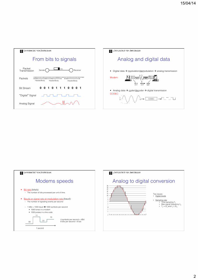
Analog and digital data!!• Digital data à modulation/demodulation à analog transmission!
Modem: !
• Analog data à coder/decoder à digital transmission!CODEC:!
CODEC!
Modems speeds!• Bit rate (bits/s)!
– The number of bits processed per unit of time.!
• Bauds or signal rate or modulation rate (baud):!– The number of signaling events per second!
– 1 kBd = 1000 baud è 1000 symbols per second!• 1000 tones in a modem!• 1000 pulses in a line code!
1 second!
00!
11!
01!
10!4 symbols per second = 4Bd!8 bits per second = 8 b/s!
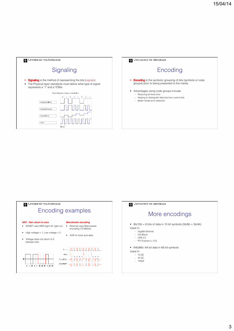
Analog to digital conversion!
Two issues:!• Digital levels!!• Sampling rate!
• Time sampling Ts!• Max signal frequency fm!• Ts =1/fs and fs ≥ 2fm!
15/04/14
3
Signaling!• Signaling is the method of representing the bits (signals)!• The Physical layer standards must define what type of signal
represents a "1" and a "0"Bits!
Encoding!• Encoding is the symbolic grouping of bits (symbols or code
groups) prior to being presented to the media.!
• Advantages using code groups include: !– Reducing bit level error!– Helping to distinguish data bits from control bits !– Better media error detection !
!!
Encoding examples!NRZ - Non return to zero!• SONET uses NRZ (light off, light on)!
• High voltage = 1; Low voltage = 0!
• Voltage does not return to 0 between bits!
Manchester encoding!• Ethernet uses Manchester
encoding (10 Mbit/s)!
• XOR of clock and data!
More encodings!• 8b/10b = 8 bits of data in 10 bit symbols (5b/6b + 3b/4b)!Used in:!
– GigaBit Ethernet!– InfiniBand!– USB 3.0!– PCI Express (< 3.0)!
• 64b/66b: 64 bit data in 66 bit symbols!Used in:!
– 10 GE!– 40 GE!– 100GE!
15/04/14
4
Transmission media!
Electrical transmission!• Data is transmitted as electrical pulses!
– A detector in the network interface of a destination device must receive a signal that can be successfully decoded to match the signal sent. !
– The timing and voltage values of these signals are susceptible to interference or "noise" from outside the communications system. !
Cabling!UTP and STP!• Unshielded Twisted Pair and
Shielded Twisted Pair!
• Four pair of twisted cables!!
Coaxial!• A single copper conductor at its
center. !• A plastic layer provides insulation
between the center conductor and a braided metal shield!
15/04/14
5
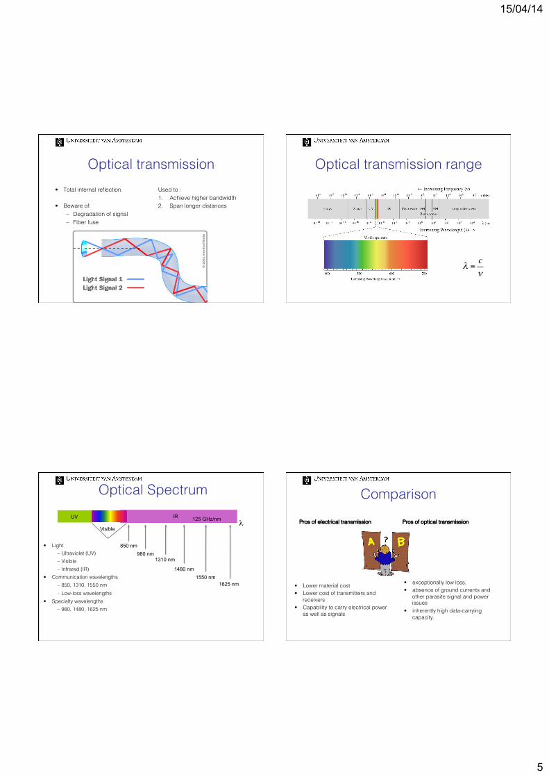
Optical transmission!• Total internal reflection.!!• Beware of:!
– Degradation of signal!– Fiber fuse!
Used to :!1. Achieve higher bandwidth !2. Span longer distances!
• Communication wavelengths!– 850, 1310, 1550 nm!– Low-loss wavelengths!
• Specialty wavelengths!– 980, 1480, 1625 nm!
UV IR
Visible
850 nm 980 nm
1310 nm
1480 nm 1550 nm
1625 nm
λ 125 GHz/nm
Optical Spectrum! Comparison!Pros of electrical transmission!
• Lower material cost!• Lower cost of transmitters and
receivers !• Capability to carry electrical power
as well as signals!!
Pros of optical transmission!
• exceptionally low loss, !• absence of ground currents and
other parasite signal and power issues !
• inherently high data-carrying capacity. !
15/04/14
6
dB#!!• Decibels (dB) is the unit to express differences in signal
strengths (loss or gain) between start and end. It’s a relative value expressing attenuation.!
!P1 and P2 power at start and end!P1/P2 is the power ratio!The decibel dB is dB= 10 Log10(P1/P2)!
E.g.:!• a ratio P1/P2 = 2 is equivalent to 3DB!!
!
!
dBm!• Decibels milliwatt (dBm) is the unit to express power of an
interface (output power and the receiver sensitivity). An absolute value.!
– X dBm = 10 Log10(Power in mW/1mW)!
Power budget!
Affected by: !– Fiber attenuation!– Splices!– Patch Panels/Connectors!– Optical components (filters, amplifiers, etc)!– Bends in fiber!– Contamination (dirt/oil on connectors)!
Input power Pin!!Pin = 0 dBm!Pin = 1mW!
Output power Pout!!Pout = -20 dBm!Pout = 0.01mW!
Optical loss: !Pin-Pout (in dB)!!Pin-Pout = 20 dB!
What about Maximum tolerated power and Maximum Launch
power?!
BER!• Bit error rate (BER): The number of erroneous bits divided by
the total number of bits transmitted, received, or processed over some stipulated period.!
Get from Tx to RX with BER < BER threshold of receiver.!(Typically 10-12)!
15/04/14
7
Fiber fundamentals!
Attenuation!
Dispersion!
Nonlinearity!
Distortion!
Eye pattern! Attenuation: !Reduces power level with distance!
Dispersion and Nonlinearities: !Erodes clarity with distance and
speed!
Signal detection and recovery!
Transmission Effects!
Optical Attenuation!• Specified in loss per
kilometer (dB/km)!– 0.40 dB/km at 1310 nm!– 0.25 dB/km at 1550 nm!
• Loss due to absorption!by impurities!
– 1400 nm peak due to OH ions!
• EDFA optical amplifiers available in 1550 window!
1310 Window
1550 Window
• Polarization Mode Dispersion (PMD) ! Single-mode fiber supports two polarization states ! Fast and slow axes have different group velocities ! Causes spreading of the light pulse!
Chromatic Dispersion !Different wavelengths travel at different speeds !
Causes spreading of the light pulse !
Dispersion !
15/04/14
8
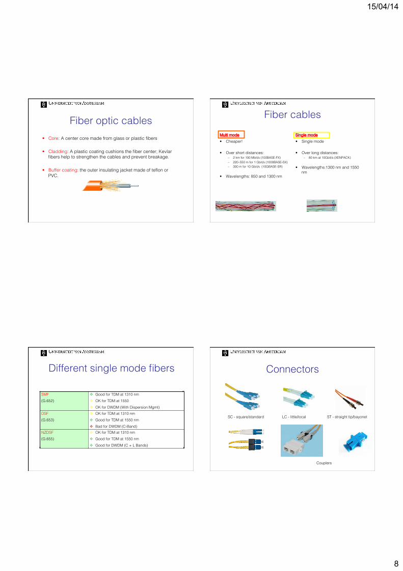
Fiber optic cables!• Core: A center core made from glass or plastic fibers!
• Cladding: A plastic coating cushions the fiber center; Kevlar fibers help to strengthen the cables and prevent breakage. !
!• Buffer coating: the outer insulating jacket made of teflon or
PVC. !
Fiber cables!Multi mode !• Cheaper!!!• Over short distances:!
– 2 km for 100 Mbit/s (100BASE-FX)!– 220–550 m for 1 Gbit/s (1000BASE-SX)!– 300 m for 10 Gbit/s (10GBASE-SR)!
• Wavelengths: 850 and 1300 nm!
Single mode!• Single mode!
• Over long distances:!– 80 km at 10Gbit/s (XENPACK)!
• Wavelengths:1300 nm and 1550 nm!
Different single mode fibers!
SMF!(G.652)!
v Good for TDM at 1310 nm!v OK for TDM at 1550!v OK for DWDM (With Dispersion Mgmt)!
DSF!(G.653)!
v OK for TDM at 1310 nm!v Good for TDM at 1550 nm!v Bad for DWDM (C-Band)!
NZDSF!(G.655)!
v OK for TDM at 1310 nm!v Good for TDM at 1550 nm!v Good for DWDM (C + L Bands)!
Connectors!
SC - square/standard! LC - little/local! ST - straight tip/bayonet!
– optics provided transmission and capacity.!– switching and intelligence handled in electronics!
Second generation networks - all optical:!– routing, switching and intelligence are moving in the optical layer.!
Basic components!• Couplers and splitters, used to combine and split signals in
the network;!– Taps are type of couplers that tap off small portion of the power from a
light stream for monitoring purposes;!
• Filters!!
• Multiplexers(mux) and demultiplexers (demux)!
Wavelength filter
λ1,λ2,λ3,λ4 λ1
λ3
λ2
λ1
λ4
λ1,λ2,λ3,λ4λ1,λ2,λ3,λ4
λ3
λ2
λ1
λ4
Wavelength crossconnect!• Cascading mux and demux can create a (static) OXC!
λ11,λ12,λ
13,λ
14
λ3
λ2
λ1
λ4
λ 21,λ12,λ3
1,λ 24
λ 21,λ22,λ3
2,λ 24 λ11,λ22,λ
23,λ
14
MEMs devices!
15/04/14
11
Amplifiers!• Signals get attenuated as they travel in fibers. !• Two approaches:!
– Regenerators, converts optical into electrical signal and retransmit; !– Amplifiers:!– Amplification window, the range of wavelengths over which there is
Transmitters!Semiconductor lasers are the light source for optical transmission. They have a fixed wavelength for operation.!Think of gigabit Ethernet:!
– 1000SX!– 1000LX!– 1000ZX!
Tunable lasers can alter the wavelength of operation.!They open up the possibility to have:!
Three types of degradation!• A Light Pulse Propagating in a Fiber Experiences 3 Type of
Degradations:!
Loss of Energy!
Loss of Timing (Jitter)!t
ts Optimum !Sampling Time!
t ts Optimum !Sampling Time!
Phase Variation!
Shape Distortion!
Pulse as It Enters the Fiber! Pulse as It Exits the Fiber!
Re-Shape! DCU
The 3 R’s!The options to recover are:!
Amplify!
t ts Optimum !Sampling Time!
t ts Optimum !Sampling Time!
Re-Generate! O-E-O
Re-time, re-Transmit, re-Shape!
Phase Re-Alignment!
t ts Optimum !Sampling Time!
15/04/14
12
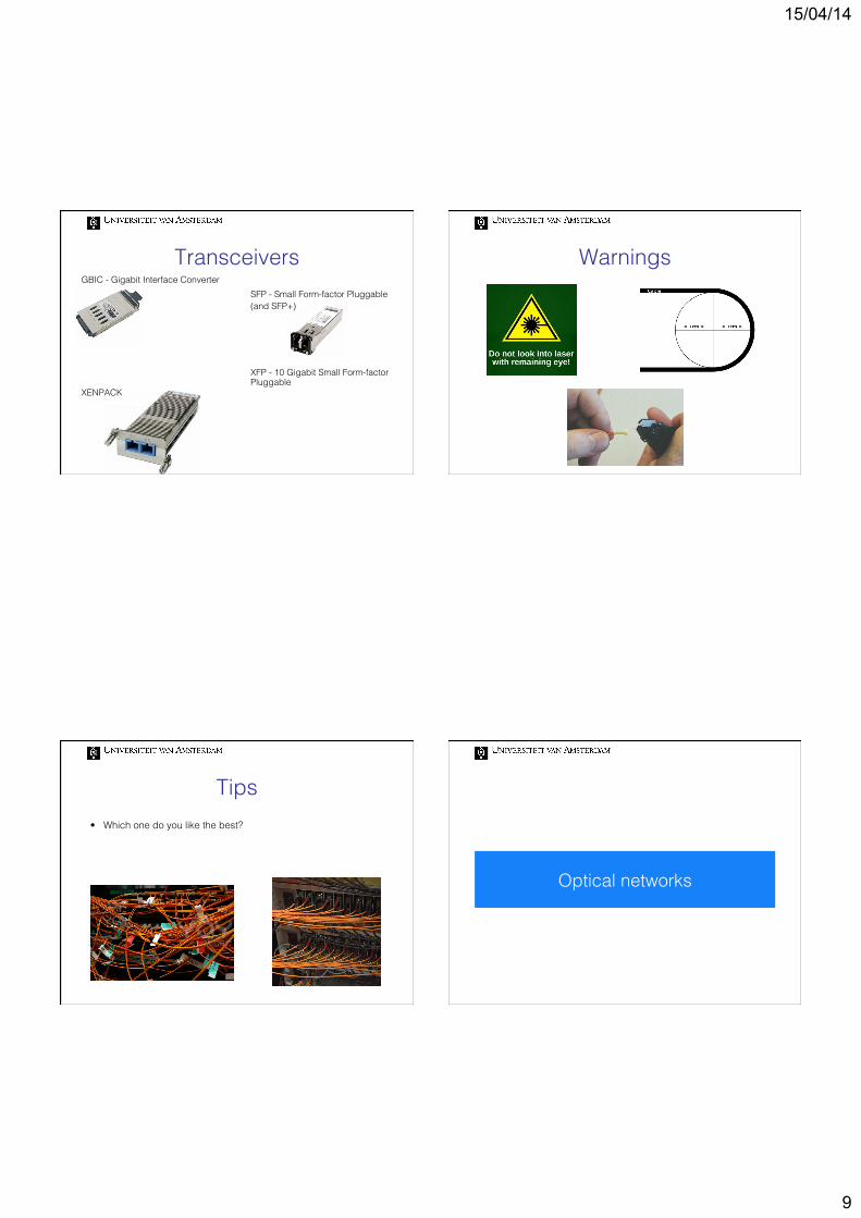
Multiplexing schemes!
TDM:!SONET/SDH!
!#(D)WDM!
Test Time!
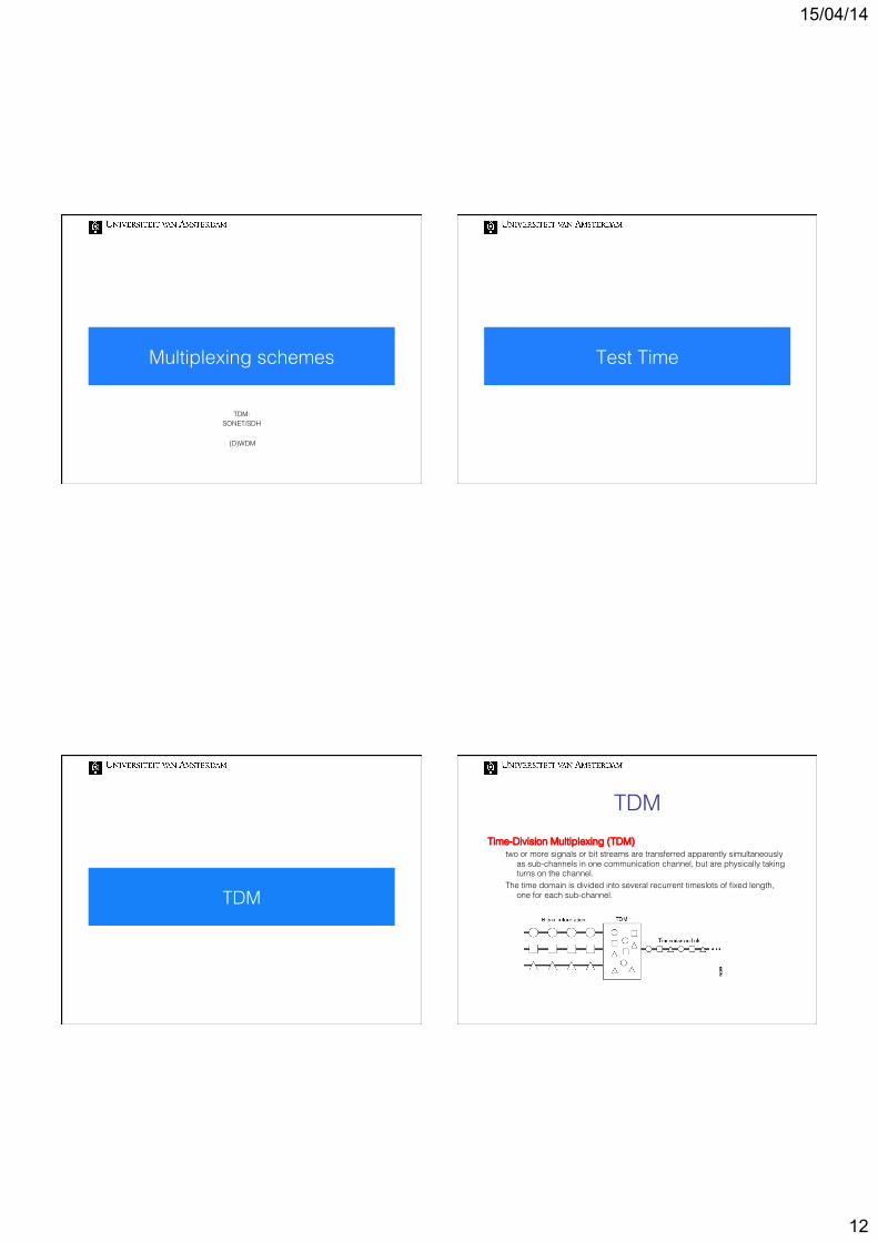
TDM!
TDM!Time-Division Multiplexing (TDM) !
two or more signals or bit streams are transferred apparently simultaneously as sub-channels in one communication channel, but are physically taking turns on the channel. !
The time domain is divided into several recurrent timeslots of fixed length, one for each sub-channel.!
!
15/04/14
13
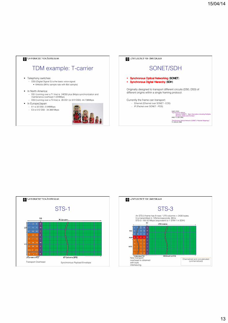
TDM example: T-carrier!• Telephony switches:!
– DS0 (Digital Signal 0) is the basic voice signal: !• 64kbit/s (8Khz sample rate with 8bit sample)!
• In North America:!– DS1 (running over a T1 line) is 24DS0 plus 8kbps synchronization and
maintenance overhead:1.544Mbps!– DS3 (running over a T3 line) is 28 DS1 (or 672 DS0): 44.736Mbps!
• In Europe/Japan:!– E1 is 32 DS0: 2.048Mbps!– E3 is 512 DS0: 34.368 Mbps!
SONET/SDH!• Synchronous Optical Networking (SONET) !• Synchronous Digital Hierarchy (SDH)!
Originally designed to transport different circuits (DS0, DS3) of different origins within a single framing protocol.!!Currently the frame can transport:!
– Ethernet (Ethernet over SONET - EOS) !– IP (Packet over SONET - POS)!
STS-3!An STS-3 frame has 9 rows * 270 columns = 2430 bytes.!It is transmitted in 125microseconds: 8Khz!STS-3: 155.52 Mbps (equivalent to 1 STM-1 in SDH)!
New transport overhead is obtained with byte interleaving.!
SONET Layers!• SONET/SDH can be layered according to functions.!
Line
Path
Section
Photonic
Section
Photonic
Line
Path
Section
Photonic
Section
Photonic
Line
Section
Photonic
Line
Section
Photonic
15/04/14
15
Packets over SONET/SDH!
Learn more: PPP over SONET/SDH RFC 2615- Jun.1999
GFP!• Generic Framing Protocol: it allows to map client packets into
the SONET/SDH payloads, in order to transport non-TDM traffic more efficiently.!
!!
Ethe
rnet
fra
me!
(D)WDM!
WDM!Wavelength-division multiplexing (WDM) !
multiplexes multiple optical carrier signals on a single optical fiber by using different wavelengths (colours) of laser light to carry different signals.!
15/04/14
16
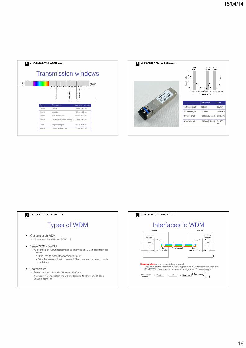
Transmission windows!
Band ##! Description! Wavelength range!O band! original! 1260 to 1360 nm!
E band! extended! 1360 to 1460 nm!
S band! short wavelengths! 1460 to 1530 nm!
C band! conventional ("erbium window")! 1530 to 1565 nm!
L band! long wavelengths! 1565 to 1625 nm!
U band! ultralong wavelengths! 1625 to 1675 nm!
! Wavelength! tLoss!
1rst wavelength" 850nm" 3dB/km"
2nd wavelength" 1310nm" 0.4dB/km"
3rd wavelength" 1550nm (C band)" 0.2dB/km"
4th wavelength" 1625nm (L band)" 0.2 dB/km"
Types of WDM!• (Conventional) WDM!
– 16 channels in the C-band(1550nm)!
• Dense WDM - DWDM!– 40 channels at 100Ghz spacing or 80 channels at 50 Ghz spacing in the
C-band!• Ultra DWDM extend the spacing to 2GHz#!• With Raman amplification instead EDFA channles double and reach
the L-band!
• Coarse WDM!– Started with two channels (1310 and 1550 nm)!– Nowadays 16 channels in the O-band (around 1310nm) and C-band
(around 1550nm)!
Interfaces to WDM!
Transponders are an essential component:!#They convert the incoming optical signal in an ITU-standard wavelength.!#SONET/SDH from client -> an electrical signal -> ITU wavelength!
15/04/14
17
DS-1 DS-3 OC-1 OC-3
OC-12 OC-48
OC-12c OC-48c
OC-192c
Fiber
DWDM OADM
SONET ADM
Fiber
TDM and DWDM Comparison!
• TDM (SONET/SDH)!– Takes signals and
multiplexes them to a single higher optical bit rate!
– E/O or O/E/O conversion!!
• (D)WDM!– Takes multiple optical !signals and multiplexes !onto a single fiber!– No signal format conversion!
OTN!• OTN – Optical Transport Network!Intends to replace SONET/SDH as transport mechanisms, as it betters integrate with DWDM.!!OTN specifies a digital wrapper to create an optical data unit (ODU), !
Learn more: ITU G.709 “Optical Transport Network (OTN)" ITU G.872 "Architecture for the Optical Transport Network (OTN)"
CISCO CRS!
Available Interface modules:!!• 1-Port OC-768C/STM-256C
Tunable WDMPOS!
• 4-Port 10GE Tunable WDMPHY!
• 4-Port OC-192c/STM-64 POS/DPT!
• 8-Port 10 Gigabit Ethernet!
• 16-Port OC-48c/STM-16c POS/DPT!
!• Cisco CRS Single-Port
OC-768c/STM-256c POS!
Juniper T4000!Available line cards:!!• 100-Gigabit Ethernet!