111 PART 3 STORM DRAINS Abbreviations and Symbols Plan 301 Abbreviations and symbols for storm drains ......................................... 113 Catch Basins, Inlets, Outlets and Hardware 302 30" Frame and cover ............................................................................. 115 303 44" Frame and cover ............................................................................. 119 304 48" Cover and frame.............................................................................. 121 305 51" Cover and frame.............................................................................. 123 308 35 1/2" Grate and frame with adjustable curb box ................................ 129 309 47 3/4" Grate and frame ........................................................................ 131 310 48" Grate and frame .............................................................................. 135 315 Catch basin ............................................................................................ 137 316 Combination inlet/cleanout box ............................................................. 141 317 Curb inlet/outlet...................................................................................... 143 320 Debris grate inlet .................................................................................... 147 321 Automatic flap gate (pressurized storm drains) ..................................... 149 322 Curb outlet ............................................................................................. 151 323 Pipe outfall access control rack ............................................................. 153 Cleanout Box and Hardware 330 Cleanout box.......................................................................................... 155 331 Cleanout box.......................................................................................... 157 332 Cast in-place manhole ........................................................................... 159 335 Adjust reinforced concrete deck to grade ............................................. 161 Manhole and Hardware 341 Precast manhole ................................................................................... 163 345 Concrete deck........................................................................................ 167 360 Raise frame to grade – plastic form ...................................................... 169 361 Raise frame to grade – grade ring......................................................... 171 362 Cover collar for storm drains ................................................................. 173 Piping 372 Area drain .............................................................................................. 175 373 Concrete pier ......................................................................................... 177 Trenching 381 Trench Backfill ....................................................................................... 179 382 Pipe zone backfill ................................................................................... 181
Transcript
111
PART 3
STORM DRAINS Abbreviations and Symbols Plan 301 Abbreviations and symbols for storm drains ......................................... 113 Catch Basins, Inlets, Outlets and Hardware 302 30" Frame and cover ............................................................................. 115 303 44" Frame and cover ............................................................................. 119 304 48" Cover and frame.............................................................................. 121 305 51" Cover and frame.............................................................................. 123 308 35 1/2" Grate and frame with adjustable curb box ................................ 129 309 47 3/4" Grate and frame........................................................................ 131 310 48" Grate and frame .............................................................................. 135 315 Catch basin............................................................................................ 137 316 Combination inlet/cleanout box ............................................................. 141 317 Curb inlet/outlet...................................................................................... 143 320 Debris grate inlet.................................................................................... 147 321 Automatic flap gate (pressurized storm drains)..................................... 149 322 Curb outlet ............................................................................................. 151 323 Pipe outfall access control rack............................................................. 153 Cleanout Box and Hardware 330 Cleanout box.......................................................................................... 155 331 Cleanout box.......................................................................................... 157 332 Cast in-place manhole........................................................................... 159 335 Adjust reinforced concrete deck to grade ............................................. 161 Manhole and Hardware 341 Precast manhole ................................................................................... 163 345 Concrete deck........................................................................................ 167 360 Raise frame to grade – plastic form ...................................................... 169 361 Raise frame to grade – grade ring......................................................... 171 362 Cover collar for storm drains ................................................................. 173 Piping 372 Area drain .............................................................................................. 175 373 Concrete pier ......................................................................................... 177 Trenching 381 Trench Backfill ....................................................................................... 179 382 Pipe zone backfill................................................................................... 181
eric.major
Text Box
Plan 382 Replaced with Pipe Laying Flow Chart and Drawing
eric.major
Line
112
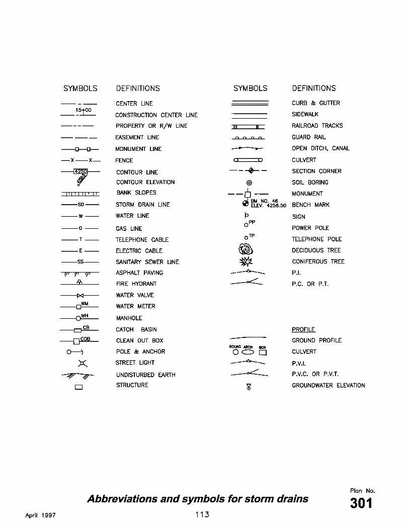
Abbreviations and symbols for storm drains 1. LETTERING SIZE: 100 Leroy minimum except for line type and other background
information. Use 120 Leroy for new work installation. 2. LETTERING STYLE: Capital letters preferred. 3. EXISTING IMPROVEMENTS: Shown in light shaded dashed line. 4. NEW IMPROVEMENTS: Shown in solid continuous line.
114
30" Frame and cover – type A 1. CASTINGS: Grey iron class 35 minimum per ASTM A 48. 2. COATINGS: Except machined surfaces, coat all metal parts with asphaltum paint. 3. INSCRIPTIONS: Cast the words "STORM DRAIN" on the cover flush with the
surface finish. 4. HEAT NUMBER: Place foundry and heat number on the inside of the frame and on
the bottom of the cover. 5. FIT: � designates machined surface. Give the frame and cover a machine finish so
the cover will not rock. 6. LOCKING: Provide covers for manholes located in easements, rights-of-way, alleys,
parking lots, and all other places except paved streets, with allen socket set screw locking devices. Drill and tap two holes to a depth of 1 inch at 90 degrees to pry hole and install 3/4 x 3/4 inch allen socket set screws.
7. CLEANOUT STRUCTURE: See Plan No. 330. 8. MANHOLE STRUCTURES: See Plan No. 341.
116
30" Frame and cover – type B 1. CASTINGS: Grey iron class 35 minimum per ASTM A 48. 2. COATINGS: Except machined surfaces, coat all metal parts with asphaltum paint. 3. INSCRIPTIONS: Cast the words "STORM DRAIN" on the cover flush with the
surface finish. 4. HEAT NUMBER: Place foundry and heat number on the inside of the frame and on
the bottom of the cover. 5. FIT: � designates machined surface. Give the frame and cover a machine finish so
the cover will not rock. 6. LOCKING: Provide covers for manholes located in easements, rights-of-way, alleys,
parking lots, and all other places except paved streets, with allen socket set screw locking devices. Drill and tap two holes to a depth of 1 inch at 90 degrees to pry hole and install 3/4 x 3/4 inch allen socket set screws.
7. CLEANOUT STRUCTURE: See Plan No. 330. 8. MANHOLE STRUCTURES: See Plan No. 341.
118
44" Frame and cover 1. CASTINGS: Grey iron class 35 minimum per ASTM A 48. 2. COATINGS: Except machined surfaces, coat all metal parts with asphaltum paint. 3. INSCRIPTIONS: Cast the words "STORM DRAIN" on the cover flush with the
surface finish. 4. HEAT NUMBER: Place foundry and heat number on the inside of the frame and on
the bottom of the cover. 5. FIT: � designates machined surface. Give the frame and cover a machine finish so
the cover will not rock. 6. LOCKING: Provide covers for manholes located in easements, rights-of-way, alleys,
parking lots, and all other places except paved streets, with allen socket set screw locking devices. Drill and tap two holes to a depth of 1 inch at 90 degrees to pry hole and install 3/4 x 3/4 inch allen socket set screws.
7. CLEANOUT STRUCTURE: See Plan No. 330. 8. MANHOLE STRUCTURES: See Plan No. 341.
120
48" Cover and frame 1. CASTINGS: Grey iron class 35 minimum per ASTM A 48. 2. COATINGS: Except machined surfaces, coat all metal parts with asphaltum paint. 3. CONCRETE BOX: See Plan No. 331. 4. HEAT NUMBER: Place foundry and heat number on the inside of the frame and on
the bottom of the cover.
122
51" Cover and frame - cover 1. CASTINGS: Grey iron class 35 minimum per ASTM A 48. 2. COATINGS: Except machined surfaces, coat all metal parts with asphaltum paint. 3. PRE-DRILL: Drill and tap covers at factory to match frames. Keep covers and
frames bolted together prior to and during installation. 4. ACCESSORIES: Stainless steel bolts, washers, and accessories required. See
APWA Section 05 05 23. 5. CONCRETE BOX: See Plan No. 332. 6. HEAT NUMBER: Place foundry and heat number on the inside of the frame and on
the bottom of the cover.
124
51" Cover and frame - type A frame 1. NARRATIVE: Use this frame and cover in roadways and other areas subject to
heavy loadings. This cover fits Type A, B, C and D frames. 2. FRAME: ASTM A 36 steel, or ASTM A 48 grey iron class 35 minimum. 3. COATINGS: Except machined surfaces, coat all metal parts with asphaltum paint. 4. PRE-DRILL: Drill and tap covers at factory to match frames. Keep covers and
frames bolted together prior to and during installation. 5. CONCRETE BOX: See Plan No. 332.
126
51" Cover and frame - type `B', `C', or `D' frame 1. FRAME: ASTM A 36 steel, or ASTM A 48 grey iron class 35 minimum. 2. COATINGS: Except machined surfaces, coat all metal parts with asphaltum paint. 3. PRE-DRILL: Drill and tap covers at factory to match frames. Keep covers and
frames bolted together prior to and during installation. 4. CONCRETE BOX: See Plan No. 332.
128
35 1/2" Grate and frame with adjustable curb box 1. CASTING: Grey iron class 35 minimum per ASTM A 48. 2. COATINGS: Except machined surfaces, coat all metal parts with asphaltum paint. 3. INLET BOX: See Plan No. 315.
130
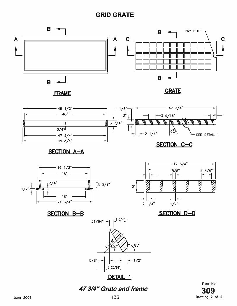
47 3/4" Grate and frame 1. CASTING: Grey iron class 35 minimum per ASTM A 48. 2. COATINGS: Except machined surfaces, coat all metal parts with asphaltum paint. 3. INLET BOX: See Plan No. 331.
132
47 3/4" Grate and frame 1. CASTING: Grey iron class 35 minimum per ASTM A 48. 2. COATINGS: Except machined surfaces, coat all metal parts with asphaltum paint. 3. INLET BOX: See Plan No. 331.
134
48" Grate and frame 1. CAST IRON FRAMES: Grey iron class 35 minimum per ASTM A 48. Cast frame and
lugs as one solid, complete unit. 2. STEEL FRAMES: Studs may be welded to the frame. Use ASTM A 36 steel. 3. COATINGS: Except machined surfaces, coat all metal parts with asphaltum paint. 4. INLET BOX: See Plan No. 331.
136
Catch basin 1. UNTREATED BASE COURSE: Provide material specified in APWA Section 32 11 23.
A. Do not use gravel as a substitute for untreated base course without ENGINEER’s permission.
B. Place material per APWA Section 31 23 23. C. Compact per APWA Section 31 23 26 to a modified proctor density of 95 percent
or greater. Maximum lift thickness before compaction is 8 inches when using riding compaction equipment or 6 inches when using hand held compaction equipment.
2. BACKFILL: Provide and place per APWA Section 31 23 23 on all sides of basin.
Compact per APWA Section 31 23 26 to a modified proctor density of 95 percent or greater. Maximum lift thickness is 8 inches before compaction.
3. REINFORCEMENT: ASTM A 615, grade 60, deformed steel. 4. CONCRETE: Class 4000 per APWA Section 03 30 04. Place concrete per APWA
Section 03 30 10 Cure per APWA Section 03 39 00. 5. PIPE LATERALS: The drawing shows alternate connections to the catch basin.
Refer to construction drawings for connection locations. 6. CURB FACE OPENING: Make opening at least 4 inches high. Provide at least a 2
inch drop between the “begin warp” line in the gutter flow-line and the top of the grate at the curb face opening.
138
Catch basin 1. UNTREATED BASE COURSE: Provide material specified in APWA Section 32 11 23.
A. Do not use gravel as a substitute for untreated base course without ENGINEER’s permission.
B. Place material per APWA Section 31 23 23. C. Compact per APWA Section 31 23 26 to a modified proctor density of 95 percent
or greater. Maximum lift thickness before compaction is 8 inches when using riding compaction equipment or 6 inches when using hand held compaction equipment.
2. BACKFILL: Provide and place per APWA Section 31 23 23 on all sides of basin.
Compact per APWA Section 31 23 26 to a modified proctor density of 95 percent or greater. Maximum lift thickness is 8 inches before compaction.
3. REINFORCEMENT: ASTM A 615, grade 60, deformed steel. 4. CONCRETE: Class 4000 per APWA Section 03 30 04. Place concrete per APWA
Section 03 30 10. Cure per APWA Section 03 39 00. 5. PIPE LATERALS: The drawing shows alternate connections to the catch basin.
Refer to construction drawings for connection locations. 6. CURB FACE OPENING: Make opening at least 4 inches high. Provide at least a 2
inch drop between the “begin warp” line in the gutter flow-line and the top of the grate at the curb face opening.
140
Combination inlet / cleanout box 1. UNTREATED BASE COURSE: Provide material specified in APWA Section 32 11 23.
A. Do not use gravel as a substitute for untreated base course without ENGINEER’s permission.
B. Place material per APWA Section 31 23 23. C. Compact per APWA Section 31 23 26 to a modified proctor density of 95 percent
or greater. Maximum lift thickness before compaction is 8 inches when using riding compaction equipment or 6 inches when using hand held compaction equipment.
2. BACKFILL: Provide and place per APWA Section 31 23 23 on all sides of basin.
Compact per APWA Section 31 23 26 to a modified proctor density of 95 percent or greater. Maximum lift thickness is 8 inches before compaction.
3. REINFORCEMENT: ASTM A 615, grade 60, deformed steel. See APWA Section 03
20 00 requirements. 4. CONCRETE: Class 4000 per APWA Section 03 30 04. Place concrete per APWA
Section 03 30 10. Cure per APWA Section 03 39 00. 5. PIPE LATERALS: The drawing shows alternate connections to the catch basin.
Refer to construction drawings for connection locations. 6. LADDER RUNGS: Provide plastic coated steel ladder rungs in boxes over 6 feet
deep. Place bottom rung 6 inches above top of pipe. 7. CURB FACE OPENING: Make opening at least 4 inches high. Provide at least a 2
inch drop from the concrete gutter flow-line to the top of the grate at the curb face opening.
142
Curb inlet / outlet 1. UNTREATED BASE COURSE: Provide material specified in APWA Section 32 11 23.
A. Do not use gravel as a substitute for untreated base course without ENGINEER’s permission.
B. Place material per APWA Section 31 23 23. C. Compact per APWA Section 31 23 26 to a modified proctor density of 95 percent
or greater. Maximum lift thickness before compaction is 8 inches when using riding compaction equipment or 6 inches when using hand held compaction equipment.
2. BACKFILL: Provide and place per APWA Section 31 23 23 on all sides of basin.
Compact per APWA Section 31 23 26 to a modified proctor density of 95 percent or greater. Maximum lift thickness is 8 inches before compaction.
3. REINFORCEMENT: ASTM A 615, grade 60, deformed steel. See APWA Section 03
20 00 requirements. 4. CONCRETE: Class 4000 per APWA Section 03 30 04. Place concrete per APWA
Section 03 30 10. Cure per APWA Section 03 39 00. 5. PIPE LATERALS: The drawing shows alternate connections to the catch basin.
Refer to construction drawings for connection locations. 6. FRAME AND COVER: Grey iron class 30 minimum per ASTM A 48. Coat all metal
parts with asphaltum paint. 7. LADDER RUNGS: Provide plastic coated steel ladder rungs in boxes over 4 feet
deep. A. If V = 3 feet or less, place one step above the floor of the basin. B. If V = 3 feet or more, place steps at 12 inch intervals from the floor of the basin
with the top step at least 12 inches below the top of the manhole. 8. INSTALLATION:
A. Locate connector pipe at the downstream end of the basin unless specifically noted otherwise on the construction drawings. Trim pipe to the final shape and length before placement of concrete.
B. Make smooth curves at sill and sidewall at the gutter opening. Provide all exposed edges and corners with 1/2 inch radius edge finish. Match grade, slope, color and finish of adjacent curb and walkways.
C. Make curb opening at least 4 inches high. Provide at least a 2 inch drop from the concrete gutter flow-line to the top of the grate at the curb face opening.
144
Curb inlet / outlet 1. STEEL: ASTM A 36 hot dip galvanize after fabrication.
146
Debris grate inlet 1. BOLTS: Use 1/2 inch stainless steel bolts and 1/8 inch stainless steel washers. 2. STEEL: ASTM A 36 steel. 3. JOINTS: All joints to be welded. 4. COATING: Coat all metal parts with asphaltum paint.
148
Automatic flap gate (pressurized storm drains) 1. BACKFILL: Provide and place per APWA Section 31 23 23. Compact per APWA
Section 31 23 26 to a modified proctor density of 95 percent or greater. Maximum lift thickness is 8 inches before compaction.
2. REINFORCEMENT: ASTM A 615, grade 60, deformed steel. See APWA Section 03
20 00 requirements. 3. CONCRETE: Class 4000 per APWA Section 03 30 04. Place concrete per APWA
A. Mount the automatic flap gate on a concrete collar poured in the end of a junction spur.
B. Use nickel copper alloy mounting bolts and embed bolts 5 inches into the collar. C. Provide flap gate designed for 20 feet of seating head unless specified otherwise
in the Contract Documents. D. The `Y' dimension is measured at the top of the junction structure spur for
trapezoidal reinforced concrete channel. E. Flap gate may be either spigot back or flat back unless specified in the Contract
Documents.
150
Curb outlet 1. UNTREATED BASE COURSE: Provide material specified in APWA Section 32 11 23.
A. Do not use gravel as a substitute for untreated base course without ENGINEER’s permission.
B. Place material per APWA Section 31 23 23. C. Compact per APWA Section 31 23 26 to a modified proctor density of 95 percent
or greater. Maximum lift thickness before compaction is 8 inches when using riding compaction equipment or 6 inches when using hand held compaction equipment.
2. BACKFILL: Provide and place per APWA Section 31 23 23 on all sides of basin.
Compact per APWA Section 31 23 26 to a modified proctor density of 95 percent or greater. Maximum lift thickness is 8 inches before compaction.
3. REINFORCEMENT: ASTM A 615, grade 60, deformed steel. See APWA Section
03 20 00 requirements. Center steel in walls and slabs with a minimum cover of 2 inches. Keep steel 2 inches clear around pipe and lid opening.
4. CONCRETE: Class 4000 per APWA Section 03 30 04. Place concrete per APWA
Section 03 30 10. Cure per APWA Section 03 39 00. 5. PIPE LATERALS: The drawing shows alternate connections to the curb outlet. Refer
to construction drawings for connection locations or refer to field location of existing piping when engineering connection to existing piping.
152
Pipe outfall access control rack 1. UNTREATED BASE COURSE: Provide material specified in APWA Section 32 11 23.
A. Do not use gravel as a substitute for untreated base course without ENGINEER’s permission.
B. Place material per APWA Section 31 23 23. C. Compact per APWA Section 31 23 26 to a modified proctor density of 95 percent
or greater. Maximum lift thickness before compaction is 8 inches when using riding compaction equipment or 6 inches when using hand held compaction equipment.
2. BACKFILL: Provide and place per APWA Section 31 23 23. Compact per APWA
Section 31 23 26 to a modified proctor density of 95 percent or greater. Maximum lift thickness is 8 inches before compaction.
3. REINFORCEMENT: ASTM A 615, grade 60, deformed steel. See APWA Section
03 20 00 requirements. Weld rack with reinforcing steel or round bars of equal. 4. CONCRETE: Class 4000 per APWA Section 03 30 04. Place concrete per APWA
Section 03 30 10. Cure per APWA Section 03 39 00. 5. STEEL: ASTM A 36. 6. INSTALLATION: Provide room to lay rack flat downstream.
A. Fasten latch bracket to headwall with 1/2" x 6" stainless steel bolts and hex nuts or 1/2" stainless steel expansion bolts.
B. When rack is in the closed position, the bottom rack bar must be tight against the top of the hinge bracket so that the rack cannot be lifted off of the latch.
C. Fabricate hinge bracket from #4 rebar.
154
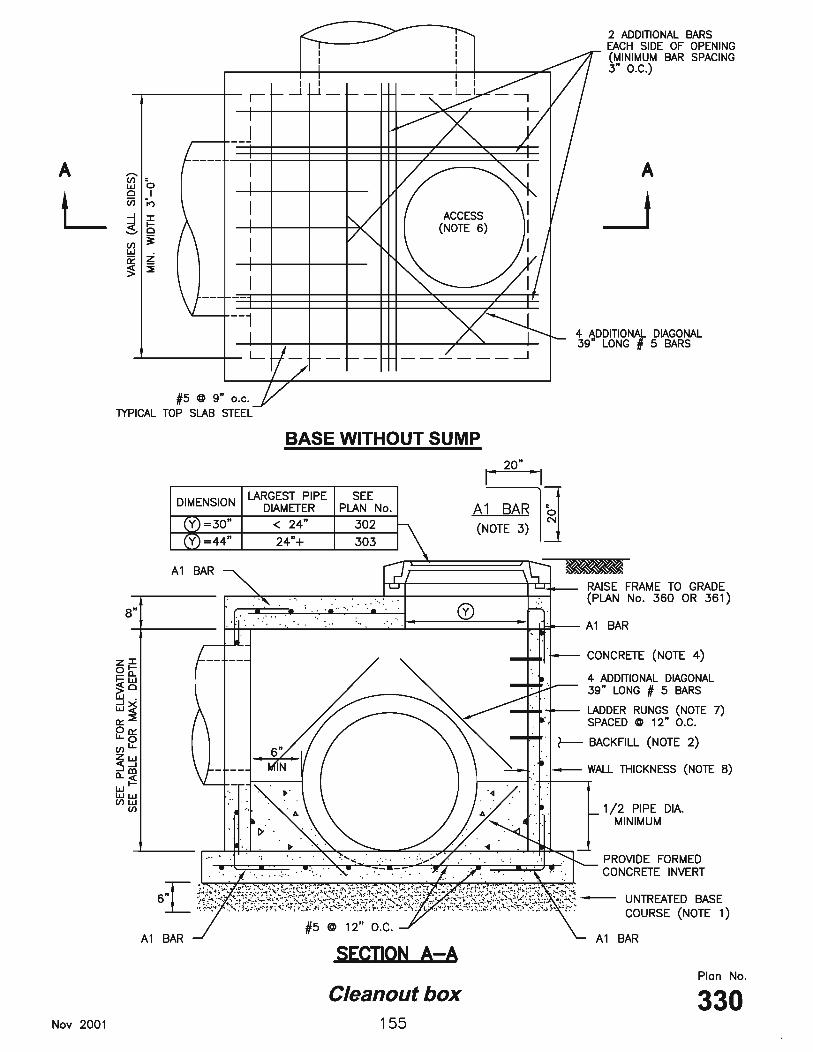
Cleanout box 1. UNTREATED BASE COURSE: Provide material specified in APWA Section 32 11 23.
A. Do not use gravel as a substitute for untreated base course without ENGINEER’s permission.
B. Place material per APWA Section 31 23 23. C. Compact per APWA Section 31 23 26 to a modified proctor density of 95 percent
or greater. Maximum lift thickness before compaction is 8 inches when using riding compaction equipment or 6 inches when using hand held compaction equipment.
2. BACKFILL: Provide and place per APWA Section 31 23 23. Compact per APWA
Section 31 23 26 to a modified proctor density of 95 percent or greater. Maximum lift thickness is 8 inches before compaction.
3. REINFORCEMENT: ASTM A 615, grade 60, deformed steel. See APWA Section
03 20 00 requirements. Center steel in walls and slabs with a minimum cover of 2 inches. Keep steel 2 inches clear around pipe and lid opening. A1 bars required at all corners, vertical and horizontal. A1 bars connecting two walls must match wall bar size and spacing. A1 bars connecting walls to top and bottom slabs must match slab steel size and spacing.
4. CONCRETE: Class 4000 per APWA Section 03 30 04. Place concrete per APWA
Section 03 30 10. Cure per APWA Section 03 39 00. 5. PIPE LATERALS: Refer to Drawings for connection locations. 6. ACCESS: Eccentric access is shown. Prior to construction, verify if concentric
access is required. Adjust reinforcement accordingly. 7. LADDER RUNGS: Plastic. Required in boxes greater than 6 feet deep with eccentric
access. Align rungs with location of access opening. Rungs not required in boxes with concentric access.
Modifications for High Water Table Wall Thickness 8 inches 10 inches 16 inches 12 inches Wall Curtain Steel #5 @ 9” #5 @ 6” #5 @ 6” #6 @ 6”
156
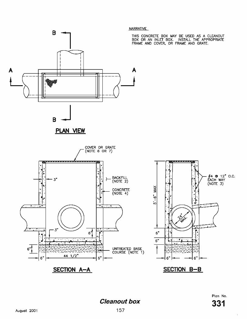
Cleanout box 1. UNTREATED BASE COURSE: Provide material specified in APWA Section 32 11 23.
A. Do not use gravel as a substitute for untreated base course without ENGINEER’s permission.
B. Place material per APWA Section 31 23 23. C. Compact per APWA Section 31 23 26 to a modified proctor density of 95 percent
or greater. Maximum lift thickness before compaction is 8 inches when using riding compaction equipment or 6 inches when using hand held compaction equipment.
2. BACKFILL: Provide and place per APWA Section 31 23 23. Compact per APWA
Section 31 23 26 to a modified proctor density of 95 percent or greater. Maximum lift thickness is 8 inches before compaction.
3. REINFORCEMENT: ASTM A 615, grade 60, deformed steel. See APWA Section
03 20 00 requirements. 4. CONCRETE: Class 4000 per APWA Section 03 30 04. Place concrete per APWA
Section 03 30 10. Cure per APWA Section 03 39 00. 5. PIPE LATERALS: The drawing shows alternate connections to the curb outlet. Refer
to Construction Drawings for connection locations. 6. COVER AND FRAME: See Plan No. 304. Adjust concrete dimensions at frame
accordingly. 7. GRATE AND FRAME: See Plan No. 309 or 310. Adjust concrete dimensions at
frame accordingly.
158
Cast in-place manhole 1. UNTREATED BASE COURSE: Provide material specified in APWA Section 32 11 23.
A. Do not use gravel as a substitute for untreated base course without ENGINEER’s permission.
B. Place material per APWA Section 31 23 23. C. Compact per APWA Section 31 23 26 to a modified proctor density of 95 percent
or greater. Maximum lift thickness before compaction is 8 inches when using riding compaction equipment or 6 inches when using hand held compaction equipment.
2. BACKFILL: Provide and place per APWA Section 31 23 23 on all sides of manhole.
Compact per APWA Section 31 23 26 to a modified proctor density of 95 percent or greater. Maximum lift thickness is 8 inches before compaction.
3. REINFORCEMENT: ASTM A 615, grade 60, deformed steel. See APWA Section
03 20 00 requirements. 4. CONCRETE: Class 4000 per APWA Section 03 30 04. Place concrete per APWA
Section 03 30 10. Cure per APWA Section 03 39 00. 5. COVER AND FRAME: See Plan No. 305. Adjust concrete dimensions at frame
accordingly.
160
Adjust reinforced concrete deck to grade 1. BACKFILL: Provide and place per APWA Section 31 23 23. Compact per APWA
Section 31 23 26 to a modified proctor density of 95 percent or greater. Maximum lift thickness is 8 inches before compaction.
2. REINFORCEMENT: ASTM A 615, grade 60, deformed steel. See APWA Section 03
20 00 requirements. 3. CONCRETE: Class 4000 per APWA Section 03 30 04. Place concrete per APWA
Section 03 30 10. Cure per APWA Section 03 39 00. 4. COVER AND FRAME: For storm drain application see Plan No. 305. Adjust
concrete dimensions at frame accordingly.
162
Precast manhole 1. UNTREATED BASE COURSE: Provide material specified in APWA Section 32 11 23.
A. Do not use gravel as a substitute for untreated base course without ENGINEER’s permission.
B. Place material per APWA Section 31 23 23. C. Compact per APWA Section 31 23 26 to a modified proctor density of 95 percent
or greater. Maximum lift thickness before compaction is 8 inches when using riding compaction equipment or 6 inches when using hand held compaction equipment.
2. BACKFILL: Provide and place per APWA Section 31 23 23. Compact per APWA
Section 31 23 26 to a modified proctor density of 95 percent or greater. Maximum lift thickness is 8 inches before compaction.
3. CONCRETE: Class 4000 per APWA Section 03 30 04. Place concrete per APWA
Section 03 30 10. Cure per APWA Section 03 39 00. 4. STATIONING AND ELEVATIONS:
A. Stations of manholes shown on the Drawings apply to the centerline of the shaft. B. Elevations shown at the shaft's center refer to the prolonged (or extended) invert
grade of the pipe. C. Inlet pipe elevation applies to a point of intersection of the inlet pipe invert to the
manhole wall. 5. CONCRETE DECK OR REDUCING RISER: When depth of manhole from pipe
invert to finish grade exceeds 6'-7", use an ASTM C 478 reducing riser cone. 6. DISTANCE “P”: “P” varies as per size of pipes, such that the horizontal inside
diameter of the pipe intersects the inside face of the riser. 7. JOINTS: Place flexible gasket-type sealant in all manhole joints. 8. BASE OF MANHOLE: Pour in one continuous operation. 9. FINISH: Provide smooth and neat finishes on interior of cones, shafts, and rings.
Imperfect moldings or honeycombs will not be accepted.
164
Precast manhole 1. UNTREATED BASE COURSE: Provide material specified in APWA Section 32 11 23.
A. Do not use gravel as a substitute for untreated base course without ENGINEER’s permission.
B. Place material per APWA Section 31 23 23. C. Compact per APWA Section 31 23 26 to a modified proctor density of 95 percent
or greater. Maximum lift thickness before compaction is 8 inches when using riding compaction equipment or 6 inches when using hand held compaction equipment.
2. BACKFILL: Provide and place per APWA Section 31 23 23. Compact per APWA
Section 31 23 26 to a modified proctor density of 95 percent or greater. Maximum lift thickness is 8 inches before compaction.
3. CONCRETE: Class 4000 per APWA Section 03 30 04. Place concrete per APWA
Section 03 30 10. Cure per APWA Section 03 39 00. 4. STATIONING AND ELEVATIONS:
A. Stations of manholes shown on the Drawings apply to the centerline of the shaft. B. Elevations shown at the shaft's center refer to the prolonged (or extended) invert
grade of the pipe. C. Inlet pipe elevation applies to a point of intersection of the inlet pipe invert to the
manhole wall. 5. CONCRETE DECK OR REDUCING RISER: When depth of manhole from pipe
invert to finish grade exceeds 6'-7", use a reducing riser section. 6. DISTANCE “P”: “P” varies as per size of pipes, such that the horizontal inside
diameter of the pipe intersects the inside face of the riser. 7 JOINTS: Place flexible gasket-type sealant in all manhole joints. 8 BASE OF MANHOLE: Pour in one continuous operation. 9 FINISH: Provide smooth and neat finishes on interior of cones, shafts, and rings.
Imperfect moldings or honeycombs will not be accepted.
166
Concrete Deck 1. REINFORCEMENT: ASTM A 615, grade 60, deformed steel. See APWA Section
03 20 00 requirements. 2. CONCRETE: Class 4000 per APWA Section 03 30 04. Place concrete per APWA
Section 03 30 10. Cure per APWA Section 03 39 00.
168
Raise frame to grade – plastic form 1. CONCRETE: Class 4000 per APWA Section 03 30 04. Place concrete per APWA
Section 03 30 10. Cure per APWA Section 03 39 00.
170
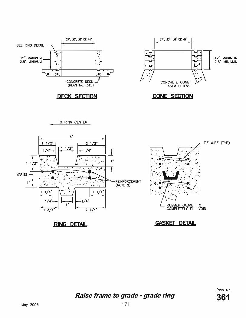
Raise frame to grade – grade ring 1. CONCRETE: Class 4000 per APWA Section 03 30 04. Place concrete per APWA
Section 03 30 10. Cure per APWA Section 03 39 00. 2. REINFORCEMENT: ASTM A 615, grade 60 steel per APWA Section 03 20 00.
A. 2 1/2" High Rings: Provide two 1/4" diameter steel hoops tied with No. 14 AWS gage wire, 8" on center.
B. 6" and 8" High Rings: Provide four 1/4" diameter steel hoops, tied with No. 14 AWS gage wire, 8" on center.
3. JOINTS: Seat rings with a compressible gasket for non-pressurized applications.
172
Cover collar for storm drains 1. CONCRETE: Class 4000 per APWA Section 03 30 04. Place concrete per APWA
Section 03 30 10. Cure per APWA Section 03 39 00. 2. JOINTS: Provide a neat straight joint between existing and new asphalt concrete
surfaces. Provide concentric circle or straight edge cut. Clean edges of all dirt, oil and loose debris.
174
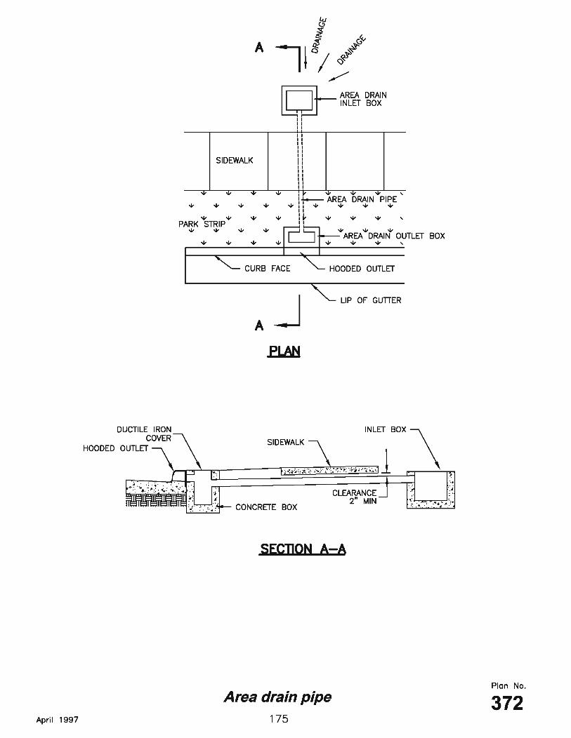
Area drain pipe 1. BACKFILL: Provide and place per APWA Section 33 05 20. Compact per APWA
Section 31 23 26 to a modified proctor density of 95 percent or greater. Maximum lift thickness is 8 inches before compaction.
176
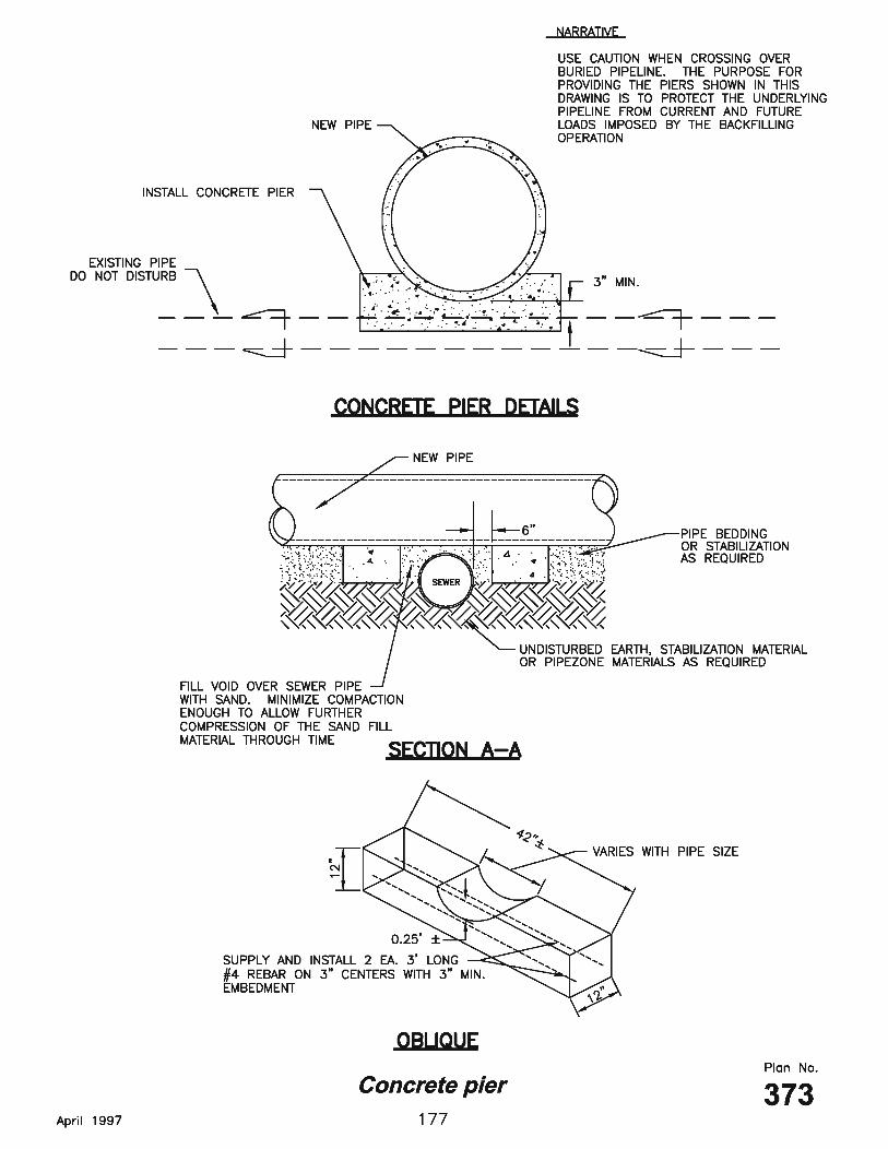
Concrete pier 1. BACKFILL: Install and compact all backfill material per APWA Section 33 05 20. 2. CONCRETE: Class 4000 per APWA Section 03 30 04.
178
Trench backfill 1. BACKFILL: Above the pipe zone.
A. Granular Fill. Limit maximum particle size to 6 inches. Place fill per APWA Section 33 05 20. Compact to a modified proctor density of 95 percent or greater. Maximum lift thickness is 8 inches before compaction. Do not use clay without ENGINEER's review and acceptance. Water jetting is NOT allowed in backfilling operation.
B. Flowable Fill. Provide and place controlled low strength material per APWA Section 31 05 15. Cure the fill before placing surface restorations.
2. LANDSCAPED RESTORATION: Provide landscaped surfaces with topsoil. Rake to
match existing grade. Replace vegetation to match pre-construction conditions. See APWA Section 32 92 00 or APWA Section 32 93 13 requirements.
3. PAVEMENT RESTORATION: Do not install asphalt or concrete surfacing until trench
compaction is accepted by ENGINEER. 4. PEA GRAVEL: Pea gravel is not allowed in any part of the trench.