168
- 447 - PART 6 REQUIREMENTS FOR THE CONSTRUCTION AND TESTING OF PACKAGINGS, INTERMEDIATE BULK CONTAINERS (IBCs), LARGE PACKAGINGS AND PORTABLE TANKS
- 447 -
PART 6
REQUIREMENTS FOR THE CONSTRUCTION AND TESTING OF PACKAGINGS, INTERMEDIATE BULK
CONTAINERS (IBCs), LARGE PACKAGINGS AND PORTABLE TANKS


- 449 -
CHAPTER 6.1
REQUIREMENTS FOR THE CONSTRUCTION AND TESTING OF PACKAGINGS
(OTHER THAN FOR DIVISION 6.2 SUBSTANCES) 6.1.1 General 6.1.1.1 The requirements of this Chapter do not apply to:
(a) Packages containing radioactive material, which shall comply with the Regulations of the International Atomic Energy Agency (IAEA), except that:
(i) Radioactive material possessing other dangerous properties (subsidiary risks) shall
also comply with special provision 172; and
(ii) Low specific activity (LSA) material and surface contaminated objects (SCO) may be carried in certain packagings defined in these Regulations provided that the supplementary provisions set out in the IAEA Regulations are also met;
(b) Pressure receptacles;
(c) Packages whose net mass exceeds 400 kg;
(d) Packagings with a capacity exceeding 450 litres.
6.1.1.2 The requirements for packagings in 6.1.4 are based on packagings currently used. In order to take into account progress in science and technology, there is no objection to the use of packagings having specifications different from those in 6.1.4, provided that they are equally effective, acceptable to the competent authority and able successfully to withstand the tests described in 6.1.1.3 and 6.1.5. Methods of testing other than those described in these Regulations are acceptable, provided they are equivalent. 6.1.1.3 Every packaging intended to contain liquids shall successfully undergo a suitable leakproofness test, and be capable of meeting the appropriate test level indicated in 6.1.5.4.3:
(a) Before it is first used for transport;
(b) After remanufacturing or reconditioning, before it is re-used for transport.
For this test, packagings need not have their own closures fitted.
The inner receptacle of composite packagings may be tested without the outer packaging provided the test results are not affected. This test is not necessary for inner packagings of combination packagings. 6.1.1.4 Packagings shall be manufactured, reconditioned and tested under a quality assurance programme which satisfies the competent authority in order to ensure that each packaging meets the requirements of this Chapter. 6.1.1.5 Manufacturers and subsequent distributors of packagings shall provide information regarding procedures to be followed and a description of the types and dimensions of closures (including required gaskets) and any other components needed to ensure that packages as presented for transport are capable of passing the applicable performance tests of this Chapter.
- 450 -
6.1.2 Code for designating types of packagings 6.1.2.1 The code consists of:
(a) An Arabic numeral indicating the kind of packaging, e.g. drum, jerrican, etc., followed by;
(b) A capital letter(s) in Latin characters indicating the nature of the material, e.g. steel, wood, etc., followed where necessary by;
(c) An Arabic numeral indicating the category of packaging within the kind to which the
packaging belongs. 6.1.2.2 In the case of composite packagings, two capital letters in Latin characters are used in sequence in the second position of the code. The first indicates the material of the inner receptacle and the second that of the outer packaging. 6.1.2.3 In the case of combination packagings, only the code number for the outer packaging is used. 6.1.2.4 The letters 'T' or 'V' or 'W' may follow the packaging code. The letter 'T' signifies a salvage packaging conforming to the requirements of 6.1.5.1.11. The letter 'V' signifies a special packaging conforming to the requirements of 6.1.5.1.7. The letter 'W' signifies that the packaging, although of the same type indicated by the code, is manufactured to a specification different from that in 6.1.4 and is considered equivalent under the requirements of 6.1.1.2. 6.1.2.5 The following numerals shall be used for the kinds of packaging:
l. Drum 2. Wooden barrel 3. Jerrican 4. Box 5. Bag 6. Composite packaging
6.1.2.6 The following capital letters shall be used for the types of material:
A. Steel (all types and surface treatments) B. Aluminium C. Natural wood D. Plywood F. Reconstituted wood G. Fibreboard H. Plastics material L. Textile M. Paper, multiwall N. Metal (other than steel or aluminium) P. Glass, porcelain or stoneware
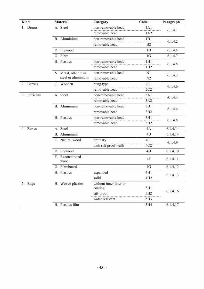
6.1.2.7 The following table indicates the codes to be used for designating types of packagings depending on the kind of packagings, the material used for their construction and their category; it also refers to the paragraphs to be consulted for the appropriate requirements:
- 451 -
Kind Material Category Code Paragraph 1. Drums A. Steel non-removable head 1A1 removable head 1A2
6.1.4.1
B. Aluminium non-removable head 1B1 removable head B2
6.1.4.2
D. Plywood 1D 6.1.4.5 G. Fibre 1G 6.1.4.7 H. Plastics non-removable head 1H1 removable head 1H2
6.1.4.8
non-removable head N1 N. Metal, other than
steel or aluminium removable head N2 6.1.4.3
2. Barrels C. Wooden bung type 2C1 removable head 2C2
6.1.4.6
3. Jerricans A. Steel non-removable head 3A1 removable head 3A2
6.1.4.4
B. Aluminium non-removable head 3B1 removable head 3B2
6.1.4.4
H. Plastics non-removable head 3H1 removable head 3H2
6.1.4.8
4. Boxes A. Steel 4A 6.1.4.14 B. Aluminium 4B 6.1.4.14 C. Natural wood ordinary 4C1 with sift-proof walls 4C2
6.1.4.9
D. Plywood 4D 6.1.4.10 F. Reconstituted
wood 4F 6.1.4.11
G. Fibreboard 4G 6.1.4.12 H. Plastics expanded 4H1 solid 4H2
6.1.4.13
5. Bags H. Woven plastics without inner liner or coating 5H1
sift-proof 5H2 water resistant 5H3
6.1.4.16
H. Plastics film 5H4 6.1.4.17
- 452 -
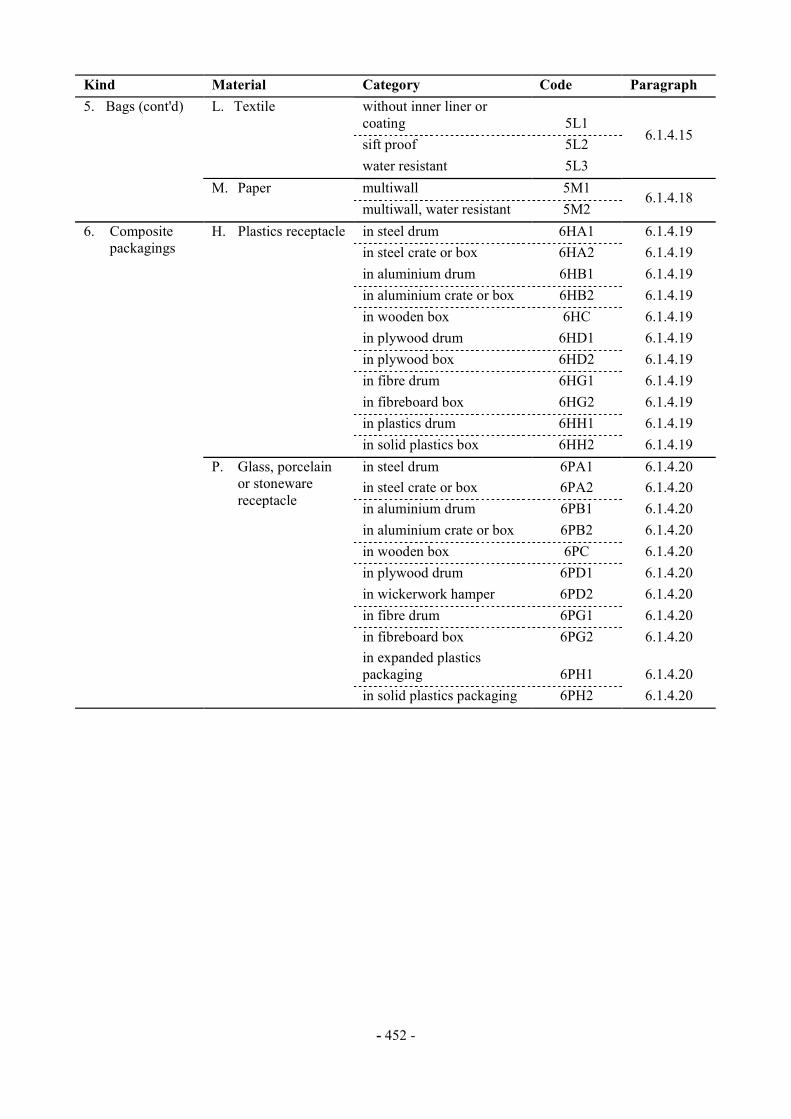
Kind Material Category Code Paragraph 5. Bags (cont'd) L. Textile without inner liner or
coating 5L1 sift proof 5L2 water resistant 5L3
6.1.4.15
multiwall 5M1
M. Paper multiwall, water resistant 5M2
6.1.4.18
in steel drum 6HA1 6.1.4.19 in steel crate or box 6HA2 6.1.4.19 in aluminium drum 6HB1 6.1.4.19 in aluminium crate or box 6HB2 6.1.4.19 in wooden box 6HC 6.1.4.19 in plywood drum 6HD1 6.1.4.19 in plywood box 6HD2 6.1.4.19 in fibre drum 6HG1 6.1.4.19 in fibreboard box 6HG2 6.1.4.19 in plastics drum 6HH1 6.1.4.19
6. Composite packagings
H. Plastics receptacle
in solid plastics box 6HH2 6.1.4.19 in steel drum 6PA1 6.1.4.20 in steel crate or box 6PA2 6.1.4.20 in aluminium drum 6PB1 6.1.4.20 in aluminium crate or box 6PB2 6.1.4.20 in wooden box 6PC 6.1.4.20 in plywood drum 6PD1 6.1.4.20 in wickerwork hamper 6PD2 6.1.4.20 in fibre drum 6PG1 6.1.4.20
P. Glass, porcelain or stoneware receptacle
in fibreboard box 6PG2 6.1.4.20 in expanded plastics packaging 6PH1 6.1.4.20
in solid plastics packaging 6PH2 6.1.4.20
- 453 -
6.1.3 Marking NOTE 1: The marking indicates that the packaging which bears it corresponds to a successfully tested design type and that it complies with the requirements of this Chapter which are related to the manufacture, but not to the use, of the packaging. In itself, therefore, the mark does not necessarily confirm that the packaging may be used for any substance: generally the type of packaging (e.g. steel drum), its maximum capacity and/or mass, and any special requirements are specified for each substance in Part 3 of these Regulations. NOTE 2: The marking is intended to be of assistance to packaging manufacturers, reconditioners, packaging users, carriers and regulatory authorities. In relation to the use of a new packaging, the original marking is a means for its manufacturer(s) to identify the type and to indicate those performance test regulations that have been met. NOTE 3: The marking does not always provide full details of the test levels, etc., and these may need to be taken further into account, e.g. by reference to a test certificate, to test reports or to a register of successfully tested packagings. For example, a packaging having an X or Y marking may be used for substances to which a packing group having a lesser degree of danger has been assigned with the relevant maximum permissible value of the relative density∗∗∗∗ determined by taking into account the factor 1.5 or 2.25 indicated in the test requirements for packagings in 6.1.5 as appropriate, i.e. packing group I packaging tested for products of relative density 1.2 could be used as a packing group II packaging for products of relative density 1.8 or a packing group III packaging of relative density 2.7, provided of course that all the performance criteria can still be met with the higher relative density product. 6.1.3.1 Each packaging intended for use according to these Regulations shall bear markings which are durable, legible and placed in a location and of such a size relative to the packaging as to be readily visible. For packages with a gross mass of more than 30 kg, the markings or a duplicate thereof shall appear on the top or on a side of the packaging. Letters, numerals and symbols shall be at least 12 mm high, except for packagings of 30 litres or 30 kg capacity or less, when they shall be at least 6 mm in height and for packagings of 5 litres or 5 kg or less when they shall be of an appropriate size.
The marking shall show: (a) The United Nations packaging symbol
This shall not be used for any purpose other than certifying that a packaging complies with the relevant regulations in this Chapter. For embossed metal packagings the capital letters "UN" may be applied as the symbol;
(b) The code designating the type of packaging according to 6.1.2;
(c) A code in two parts:
(i) a letter designating the packing group(s) for which the design type has been
successfully tested:
X for Packing Groups I, II and III Y for Packing Groups II and III Z for Packing Group III only;
∗∗∗∗ Relative density (d) is considered to be synonymous with Specific Gravity (SG) and is used throughout this text.
- 454 -
(ii) the relative density, rounded off to the first decimal, for which the design type has been tested for packagings without inner packagings intended to contain liquids; this may be omitted when the relative density does not exceed 1.2. For packagings intended to contain solids or inner packagings, the maximum gross mass in kilograms;
(d) Either the letter "S" denoting that the packaging is intended for the transport of solids or
inner packagings or, for packagings (other than combination packagings) intended to contain liquids, the hydraulic test pressure which the packaging was shown to withstand in kPa rounded down to the nearest 10 kPa;
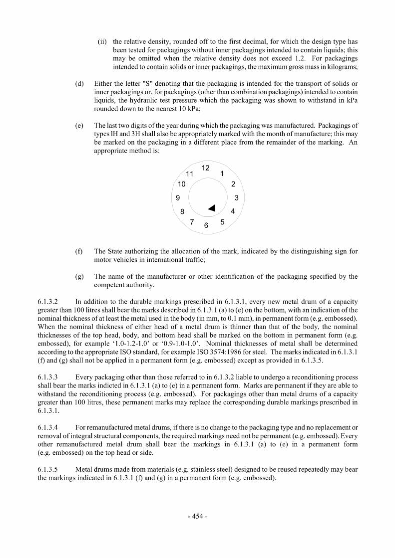
(e) The last two digits of the year during which the packaging was manufactured. Packagings of
types lH and 3H shall also be appropriately marked with the month of manufacture; this may be marked on the packaging in a different place from the remainder of the marking. An appropriate method is:
(f) The State authorizing the allocation of the mark, indicated by the distinguishing sign for motor vehicles in international traffic;
(g) The name of the manufacturer or other identification of the packaging specified by the
competent authority. 6.1.3.2 In addition to the durable markings prescribed in 6.1.3.1, every new metal drum of a capacity greater than 100 litres shall bear the marks described in 6.1.3.1 (a) to (e) on the bottom, with an indication of the nominal thickness of at least the metal used in the body (in mm, to 0.1 mm), in permanent form (e.g. embossed). When the nominal thickness of either head of a metal drum is thinner than that of the body, the nominal thicknesses of the top head, body, and bottom head shall be marked on the bottom in permanent form (e.g. embossed), for example ‘1.0-1.2-1.0’ or ‘0.9-1.0-1.0’. Nominal thicknesses of metal shall be determined according to the appropriate ISO standard, for example ISO 3574:1986 for steel. The marks indicated in 6.1.3.1 (f) and (g) shall not be applied in a permanent form (e.g. embossed) except as provided in 6.1.3.5. 6.1.3.3 Every packaging other than those referred to in 6.1.3.2 liable to undergo a reconditioning process shall bear the marks indicted in 6.1.3.1 (a) to (e) in a permanent form. Marks are permanent if they are able to withstand the reconditioning process (e.g. embossed). For packagings other than metal drums of a capacity greater than 100 litres, these permanent marks may replace the corresponding durable markings prescribed in 6.1.3.1. 6.1.3.4 For remanufactured metal drums, if there is no change to the packaging type and no replacement or removal of integral structural components, the required markings need not be permanent (e.g. embossed). Every other remanufactured metal drum shall bear the markings in 6.1.3.1 (a) to (e) in a permanent form (e.g. embossed) on the top head or side. 6.1.3.5 Metal drums made from materials (e.g. stainless steel) designed to be reused repeatedly may bear the markings indicated in 6.1.3.1 (f) and (g) in a permanent form (e.g. embossed).
12
6
39
12
45
8
1011
7
- 455 -
6.1.3.6 Marking shall be applied in the sequence shown in 6.1.3.1; each element of the marking required in these sub-paragraphs and when appropriate, (h) to (j) of 6.1.3.7, shall be clearly separated, e.g. by a slash or space, so as to be easily identifiable. For examples, see 6.1.3.9. Any additional markings authorized by a competent authority shall still enable the parts of the mark to be correctly identified with reference to 6.1.3.1. 6.1.3.7 After reconditioning a packaging, the reconditioner shall apply to it, in sequence, a durable marking showing:
(h) The State in which the reconditioning was carried out, indicated by the distinguishing sign for motor vehicles in international traffic;
(i) The name of the reconditioner or other identification of the packaging specified by the
competent authority;
(j) The year of reconditioning; the letter "R"; and, for every packaging successfully passing the leakproofness test in 6.1.1.3, the additional letter "L".
6.1.3.8 When, after reconditioning, the markings required by 6.1.3.1 (a) to (d) no longer appear on the top head or the side of a metal drum, the reconditioner also shall apply them in a durable form followed by 6.1.3.7 (h), (i) and (j). These markings shall not identify a greater performance capability than that for which the original design type had been tested and marked. 6.1.3.9 Examples of markings for NEW packagings:
4G/Yl45/S/83 NL/VL823
as in 6.1.3.l (a), (b), (c), (d) and (e) as in 6.1.3.l (f) and (g)
For a new fibreboard box
lAl/Y1.4/l50/83 NL/VL824
as in 6.1.3.1 (a), (b), (c), (d) and (e) as in 6.1.3.1 (f) and (g)
For a new steel drum to contain liquids
1A2/Y150/S/83 NL/VL825
as in 6.1.3.1 (a), (b), (c), (d) and (e) as in 6.1.3.1 (f) and (g)
For a new steel drum to contain solids, or inner packagings
4HW/Y136/S/83 NL/VL826
as in 6.1.3.1 (a), (b), (c), (d) and (e) as in 6.1.3.1 (f) and (g)
For a new plastics box of equivalent specification
1A2/Y/100/91 USA/MM5
as in 6.1.3.1 (a), (b), (c), (d) and (e) as in 6.1.3.1 (f) and (g)
For a remanufactured steel drum to contain liquids
6.1.3.10 Examples of markings for RECONDITIONED packagings
lA1/Y1.4/150/83 NL/RB/85 RL
as in 6.1.3.l (a), (b), (c), (d) and (e) as in 6.1.3.7 (h), (i) and (j)
1A2/Y150/S/83 USA/RB/85 R
as in 6.1.3.1 (a), (b), (c), (d), and (e) as in 6.1.3.7 (h), (i) and (j)
- 456 -
6.1.3.11 Example of marking for SALVAGE packagings:
1A2T/Y300/S/94 USA/abc
as in 6.1.3.1 (a), (b), (c), (d) and (e) as in 6.1.3.1 (f) and (g)
NOTE: The markings, for which examples are given in 6.1.3.9, 6.1.3.10 and 6.1.3.11, may be applied in a single line or in multiple lines provided the correct sequence is respected. 6.1.4 Requirements for packagings 6.1.4.1 Steel drums
1A1 non-removable head 1A2 removable head
6.1.4.1.1 Body and heads shall be constructed of steel sheet of a suitable type and of adequate thickness in relation to the capacity of the drum and to its intended use. 6.1.4.1.2 Body seams shall be welded on drums intended to contain more than 40 litres of liquid. Body seams shall be mechanically seamed or welded on drums intended to contain solids or 40 litres or less of liquids. 6.1.4.1.3 Chimes shall be mechanically seamed or welded. Separate reinforcing rings may be applied. 6.1.4.1.4 The body of a drum of a capacity greater than 60 litres shall, in general, have at least two expanded rolling hoops or, alternatively, at least two separate rolling hoops. If there are separate rolling hoops they shall be fitted tightly on the body and so secured that they cannot shift. Rolling hoops shall not be spot welded. 6.1.4.1.5 Openings for filling, emptying and venting in the bodies or heads of non-removable head (1A1) drums shall not exceed 7 cm in diameter. Drums with larger openings are considered to be of the removable head type (1A2). Closures for openings in the bodies and heads of drums shall be so designed and applied that they will remain secure and leakproof under normal conditions of transport. Closure flanges may be mechanically seamed or welded in place. Gaskets or other sealing elements shall be used with closures, unless the closure is inherently leakproof. 6.1.4.1.6 Closure devices for removable head drums shall be so designed and applied that they will remain secure and drums will remain leakproof under normal conditions of transport. Gaskets or other sealing elements shall be used with all removable heads. 6.1.4.1.7 If materials used for body, heads, closures and fittings are not in themselves compatible with the contents to be transported, suitable internal protective coatings or treatments shall be applied. These coatings or treatments shall retain their protective properties under normal conditions of transport. 6.1.4.1.8 Maximum capacity of drum: 450 litres 6.1.4.1.9 Maximum net mass: 400 kg
- 457 -
6.1.4.2 Aluminium drums
1B1 non-removable head 1B2 removable head
6.1.4.2.1 Body and heads shall be constructed of aluminium at least 99% pure or of an aluminium base alloy. Material shall be of a suitable type and of adequate thickness in relation to the capacity of the drum and to its intended use. 6.1.4.2.2 All seams shall be welded. Chime seams, if any, shall be reinforced by the application of separate reinforcing rings. 6.1.4.2.3 The body of a drum of a capacity greater than 60 litres shall, in general, have at least two expanded rolling hoops or, alternatively, at least two separate rolling hoops. If there are separate rolling hoops they shall be fitted tightly on the body and so secured that they cannot shift. Rolling hoops shall not be spot welded. 6.1.4.2.4 Openings for filling, emptying and venting in the bodies or heads of non-removable head (1B1) drums shall not exceed 7 cm in diameter. Drums with larger openings are considered to be of the removable head type (1B2). Closures for openings in the bodies and heads of drums shall be so designed and applied that they will remain secure and leakproof under normal conditions of transport. Closure flanges shall be welded in place so that the weld provides a leakproof seam. Gaskets or other sealing elements shall be used with closures, unless the closure is inherently leakproof. 6.1.4.2.5 Closure devices for removable head drums shall be so designed and applied that they will remain secure and drums will remain leakproof under normal conditions of transport. Gaskets or other sealing elements shall be used with all removable heads. 6.1.4.2.6 Maximum capacity of drum: 450 litres 6.1.4.2.7 Maximum net mass: 400 kg 6.1.4.3 Drums of metal other than steel or aluminium
1N1 non-removable head 1N2 removable head
6.1.4.3.1 The body and heads shall be constructed of a metal or of a metal alloy other than steel or aluminium. Material shall be of a suitable type and of adequate thickness in relation to the capacity of the drum and to its intended use. 6.1.4.3.2 Chime seams, if any, shall be reinforced by the application of separate reinforcing rings. All seams, if any, shall be joined (welded, soldered, etc.) in accordance with the technical state of the art for the used metal or metal alloy. 6.1.4.3.3 The body of a drum of a capacity greater than 60 litres shall, in general, have at least two expanded rolling hoops or, alternatively, at least two separate rolling hoops. If there are separate rolling hoops they shall be fitted tightly on the body and so secured that they cannot shift. Rolling hoops shall not be spot welded.

- 458 -
6.1.4.3.4 Openings for filling, emptying and venting in the bodies or heads of non-removable head (1N1) drums shall not exceed 7 cm in diameter. Drums with larger openings are considered to be of the removable head type (1N2). Closures for openings in the bodies and heads of drums shall be so designed and applied that they will remain secure and leakproof under normal conditions of transport. Closure flanges shall be joined in place (welded, solded, etc.) in accordance with the technical state of the art for the used metal or metal alloy so that the seam join is leakproof. Gaskets or other sealing elements shall be used with closures, unless the closure is inherently leakproof. 6.1.4.3.5 Closure devices for removable head drums shall be so designed and applied that they will remain secure and drums will remain leakproof under normal conditions of transport. Gaskets or other sealing elements shall be used with all removable heads. 6.1.4.3.6 Maximum capacity of drum: 450 litres 6.1.4.3.7 Maximum net mass: 400 kg 6.1.4.4 Steel or aluminium jerricans
3A1 steel, non-removable head 3A2 steel, removable head 3B1 aluminium, non-removable head 3B2 aluminium, removable head
6.1.4.4.1 Body and heads shall be constructed of steel sheet, of aluminium at least 99% pure or of an aluminium base alloy. Material shall be of a suitable type and of adequate thickness in relation to the capacity of the jerrican and to its intended use. 6.1.4.4.2 Chimes of steel jerricans shall be mechanically seamed or welded. Body seams of steel jerricans intended to contain more than 40 litres of liquid shall be welded. Body seams of steel jerricans intended to contain 40 litres or less shall be mechanically seamed or welded. For aluminium jerricans, all seams shall be welded. Chime seams, if any, shall be reinforced by the application of a separate reinforcing ring. 6.1.4.4.3 Openings in jerricans (3A1 and 3B1) shall not exceed 7 cm in diameter. Jerricans with larger openings are considered to be of the removable head type (3A2 and 3B2). Closures shall be so designed that they will remain secure and leakproof under normal conditions of transport. Gaskets or other sealing elements shall be used with closures, unless the closure is inherently leakproof. 6.1.4.4.4 If materials used for body, heads, closures and fittings are not in themselves compatible with the contents to be transported, suitable internal protective coatings or treatments shall be applied. These coatings or treatments shall retain their protective properties under normal conditions of transport. 6.1.4.4.5 Maximum capacity of jerrican: 60 litres 6.1.4.4.6 Maximum net mass: 120 kg 6.1.4.5 Plywood drums
1D 6.1.4.5.1 The wood used shall be well-seasoned, commercially dry and free from any defect likely to lessen the effectiveness of the drum for the purpose intended. If a material other than plywood is used for the manufacture of the heads, it shall be of a quality equivalent to the plywood.
- 459 -
6.1.4.5.2 At least two-ply plywood shall be used for the body and at least three-ply plywood for the heads; the plies shall be firmly glued together by a water resistant adhesive with their grain crosswise. 6.1.4.5.3 The body and heads of the drum and their joins shall be of a design appropriate to the capacity of the drum and to its intended use. 6.1.4.5.4 In order to prevent sifting of the contents, lids shall be lined with kraft paper or some other equivalent material which shall be securely fastened to the lid and extend to the outside along its full circumference. 6.1.4.5.5 Maximum capacity of drum: 250 litres 6.1.4.5.6 Maximum net mass: 400 kg 6.1.4.6 Wooden barrels
2C1 bung type 2C2 removable head
6.1.4.6.1 The wood used shall be of good quality, straight grained, well-seasoned and free from knots, bark, rotten wood, sapwood or other defects likely to lessen the effectiveness of the barrel for the purpose intended. 6.1.4.6.2 The body and heads shall be of a design appropriate to the capacity of the barrel and to its intended use. 6.1.4.6.3 Staves and heads shall be sawn or cleft with the grain so that no annual ring extends over more than half the thickness of a stave or head. 6.1.4.6.4 Barrel hoops shall be of steel or iron of good quality. The hoops of 2C2 barrels may be of a suitable hardwood. 6.1.4.6.5 Wooden barrels 2C1: the diameter of the bunghole shall not exceed half the width of the stave in which it is placed. 6.1.4.6.6 Wooden barrels 2C2: heads shall fit tightly into the crozes. 6.1.4.6.7 Maximum capacity of barrel: 250 litres 6.1.4.6.8 Maximum net mass: 400 kg 6.1.4.7 Fibre drums
1G 6.1.4.7.1 The body of the drum shall consist of multiple plies of heavy paper or fibreboard (without corrugations) firmly glued or laminated together and may include one or more protective layers of bitumen, waxed kraft paper, metal foil, plastics material, etc. 6.1.4.7.2 Heads shall be of natural wood, fibreboard, metal, plywood, plastics or other suitable material and may include one or more protective layers of bitumen, waxed kraft paper, metal foil, plastics material, etc. 6.1.4.7.3 The body and heads of the drum and their joins shall be of a design appropriate to the capacity of the drum and to its intended use.
- 460 -
6.1.4.7.4 The assembled packaging shall be sufficiently water resistant so as not to delaminate under normal conditions of transport. 6.1.4.7.5 Maximum capacity of drum: 450 litres 6.1.4.7.6 Maximum net mass: 400 kg 6.1.4.8 Plastics drums and jerricans
1H1 drums, non-removable head 1H2 drums, removable head 3H1 jerricans, non-removable head 3H2 jerricans, removable head
6.1.4.8.1 The packaging shall be manufactured from suitable plastics material and be of adequate strength in relation to its capacity and intended use. Except for recycled plastics material as defined in 1.2.1, no used material other than production residues or regrind from the same manufacturing process may be used. The packaging shall be adequately resistant to ageing and to degradation caused either by the substance contained or by ultra-violet radiation. 6.1.4.8.2 Unless otherwise approved by the competent authority, the period of use for the transport of dangerous substances shall not exceed five years from the date of manufacture of the packaging except where a shorter period of use is prescribed because of the nature of the substance to be transported. Packagings manufactured with such recycled plastics material shall be marked "REC" near the marks prescribed in 6.1.3.1. 6.1.4.8.3 If protection against ultra-violet radiation is required, it shall be provided by the addition of carbon black or other suitable pigments or inhibitors. These additives shall be compatible with the contents and remain effective throughout the life of the packaging. Where use is made of carbon black, pigments or inhibitors other than those used in the manufacture of the tested design type, retesting may be waived if the carbon black content does not exceed 2% by mass or if the pigment content does not exceed 3% by mass; the content of inhibitors of ultra-violet radiation is not limited. 6.1.4.8.4 Additives serving purposes other than protection against ultra-violet radiation may be included in the composition of the plastics material provided that they do not adversely affect the chemical and physical properties of the material of the packaging. In such circumstances, retesting may be waived. 6.1.4.8.5 The wall thickness at every point of the packaging shall be appropriate to its capacity and intended use, taking into account the stresses to which each point is liable to be exposed. 6.1.4.8.6 Openings for filling, emptying and venting in the bodies or heads of non-removable head drums (1H1) and jerricans (3H1) shall not exceed 7 cm in diameter. Drums and jerricans with larger openings are considered to be of the removable head type (1H2 and 3H2). Closures for openings in the bodies or heads of drums and jerricans shall be so designed and applied that they will remain secure and leakproof under normal conditions of transport. Gaskets or other sealing elements shall be used with closures unless the closure is inherently leakproof. 6.1.4.8.7 Closure devices for removable head drums and jerricans shall be so designed and applied that they will remain secure and leakproof under normal conditions of transport. Gaskets shall be used with all removable heads unless the drum or jerrican design is such that, where the removable head is properly secured, the drum or jerrican is inherently leakproof.

- 461 -
6.1.4.8.8 Maximum capacity of drums and jerricans: 1H1, 1H2: 450 litres 3H1, 3H2: 60 litres 6.1.4.8.9 Maximum net mass: 1H1, 1H2: 400 kg
3H1, 3H2: 120 kg 6.1.4.9 Boxes of natural wood
4C1 ordinary 4C2 with sift-proof walls
6.1.4.9.1 The wood used shall be well-seasoned, commercially dry and free from defects that would materially lessen the strength of any part of the box. The strength of the material used and the method of construction shall be appropriate to the capacity and intended use of the box. The tops and bottoms may be made of water resistant reconstituted wood such as hardboard, particle board or other suitable type. 6.1.4.9.2 Fastenings shall be resistant to vibration experienced under normal conditions of transport. End grain nailing shall be avoided whenever practicable. Joins which are likely to be highly stressed shall be made using clenched or annular ring nails or equivalent fastenings. 6.1.4.9.3 Box 4C2: each part shall consist of one piece or be equivalent thereto. Parts are considered equivalent to one piece when one of the following methods of glued assembly is used: Lindermann joint, tongue and groove joint, ship lap or rabbet joint or butt joint with at least two corrugated metal fasteners at each joint. 6.1.4.9.4 Maximum net mass: 400 kg 6.1.4.10 Plywood boxes
4D 6.1.4.10.1 Plywood used shall be at least 3-ply. It shall be made from well-seasoned rotary cut, sliced or sawn veneer, commercially dry and free from defects that would materially lessen the strength of the box. The strength of the material used and the method of construction shall be appropriate to the capacity and intended use of the box. All adjacent plies shall be glued with water resistant adhesive. Other suitable materials may be used together with plywood in the construction of boxes. Boxes shall be firmly nailed or secured to corner posts or ends or be assembled by equally suitable devices. 6.1.4.10.2 Maximum net mass: 400 kg 6.1.4.11 Reconstituted wood boxes
4F 6.1.4.11.1 The walls of boxes shall be made of water resistant reconstituted wood such as hardboard, particle board or other suitable type. The strength of the material used and the method of construction shall be appropriate to the capacity of the boxes and to their intended use. 6.1.4.11.2 Other parts of the boxes may be made of other suitable material. 6.1.4.11.3 Boxes shall be securely assembled by means of suitable devices. 6.1.4.11.4 Maximum net mass: 400 kg
- 462 -
6.1.4.12 Fibreboard boxes
4G 6.1.4.12.1 Strong and good quality solid or double-faced corrugated fibreboard (single or multiwall) shall be used, appropriate to the capacity of the box and to its intended use. The water resistance of the outer surface shall be such that the increase in mass, as determined in a test carried out over a period of 30 minutes by the Cobb method of determining water absorption, is not greater than 155 g/m2 - see ISO 535:l991. It shall have proper bending qualities. Fibreboard shall be cut, creased without scoring, and slotted so as to permit assembly without cracking, surface breaks or undue bending. The fluting of corrugated fibreboard shall be firmly glued to the facings. 6.1.4.12.2 The ends of boxes may have a wooden frame or be entirely of wood or other suitable material. Reinforcements of wooden battens or other suitable material may be used. 6.1.4.12.3 Manufacturing joins in the body of boxes shall be taped, lapped and glued, or lapped and stitched with metal staples. Lapped joins shall have an appropriate overlap. 6.1.4.12.4 Where closing is effected by gluing or taping, a water resistant adhesive shall be used. 6.1.4.12.5 Boxes shall be designed so as to provide a good fit to the contents. 6.1.4.12.6 Maximum net mass: 400 kg 6.1.4.13 Plastics boxes
4H1 expanded plastics boxes 4H2 solid plastics boxes
6.1.4.13.1 The box shall be manufactured from suitable plastics material and be of adequate strength in relation to its capacity and intended use. The box shall be adequately resistant to ageing and to degradation caused either by the substance contained or by ultra-violet radiation. 6.1.4.13.2 An expanded plastics box shall comprise two parts made of a moulded expanded plastics material, a bottom section containing cavities for the inner packagings and a top section covering and interlocking with the bottom section. The top and bottom sections shall be designed so that the inner packagings fit snugly. The closure cap for any inner packaging shall not be in contact with the inside of the top section of this box. 6.1.4.13.3 For dispatch, an expanded plastics box shall be closed with a self-adhesive tape having sufficient tensile strength to prevent the box from opening. The adhesive tape shall be weather resistant and its adhesive compatible with the expanded plastics material of the box. Other closing devices at least equally effective may be used. 6.1.4.13.4 For solid plastics boxes, protection against ultra-violet radiation, if required, shall be provided by the addition of carbon black or other suitable pigments or inhibitors. These additives shall be compatible with the contents and remain effective throughout the life of the box. Where use is made of carbon black, pigments or inhibitors other than those used in the manufacture of the tested design type, retesting may be waived if the carbon black content does not exceed 2% by mass or if the pigment content does not exceed 3% by mass; the content of inhibitors of ultra-violet radiation is not limited. 6.1.4.13.5 Additives serving purposes other than protection against ultra-violet radiation may be included in the composition of the plastics material provided that they do not adversely affect the chemical or physical properties of the material of the box. In such circumstances, retesting may be waived.
- 463 -
6.1.4.13.6 Solid plastics boxes shall have closure devices made of a suitable material of adequate strength and so designed as to prevent the box from unintentional opening. 6.1.4.13.7 Maximum net mass 4H1: 60 kg
4H2: 400 kg 6.1.4.14 Steel or aluminium boxes
4A steel 4B aluminium
6.1.4.14.l The strength of the metal and the construction of the box shall be appropriate to the capacity of the box and to its intended use. 6.1.4.14.2 Boxes shall be lined with fibreboard or felt packing pieces or shall have an inner liner or coating of suitable material, as required. If a double seamed metal liner is used, steps shall be taken to prevent the ingress of substances, particularly explosives, into the recesses of the seams. 6.1.4.14.3 Closures may be of any suitable type; they shall remain secured under normal conditions of transport. 6.1.4.14.4 Maximum net mass: 400 kg 6.1.4.15 Textile bags
5L1 without inner liner or coating 5L2 sift-proof 5L3 water resistant
6.1.4.15.1 The textiles used shall be of good quality. The strength of the fabric and the construction of the bag shall be appropriate to the capacity of the bag and to its intended use. 6.1.4.15.2 Bags, sift-proof, 5L2: the bag shall be made sift-proof, for example by the use of:
(a) Paper bonded to the inner surface of the bag by a water resistant adhesive such as bitumen; or
(b) Plastics film bonded to the inner surface of the bag; or
(c) One or more inner liners made of paper or plastics material. 6.1.4.15.3 Bags, water resistant, 5L3: to prevent the entry of moisture the bag shall be made waterproof, for example by the use of:
(a) Separate inner liners of water resistant paper (e.g. waxed kraft paper, tarred paper or plastics-coated kraft paper); or
(b) Plastics film bonded to the inner surface of the bag; or
(c) One or more inner liners made of plastics material.
6.1.4.15.4 Maximum net mass: 50 kg

- 464 -
6.1.4.16 Woven plastics bags
5H1 without inner liner or coating 5H2 sift-proof 5H3 water resistant
6.1.4.16.1 Bags shall be made from stretched tapes or monofilaments of a suitable plastics material. The strength of the material used and the construction of the bag shall be appropriate to the capacity of the bag and to its intended use. 6.1.4.16.2 If the fabric is woven flat, the bags shall be made by sewing or some other method ensuring closure of the bottom and one side. If the fabric is tubular, the bag shall be closed by sewing, weaving or some other equally strong method of closure. 6.1.4.16.3 Bags, sift-proof, 5H2: the bag shall be made sift-proof, for example by means of:
(a) Paper or a plastics film bonded to the inner surface of the bag; or
(b) One or more separate inner liners made of paper or plastics material. 6.1.4.16.4 Bags, water resistant, 5H3: to prevent the entry of moisture, the bag shall be made waterproof, for example by means of:
(a) Separate inner liners of water resistant paper (e.g. waxed kraft paper, double-tarred kraft paper or plastics-coated kraft paper); or
(b) Plastics film bonded to the inner or outer surface of the bag; or
(c) One or more inner plastics liners.
6.1.4.16.5 Maximum net mass: 50 kg 6.1.4.17 Plastics film bags
5H4 6.1.4.17.1 Bags shall be made of a suitable plastics material. The strength of the material used and the construction of the bag shall be appropriate to the capacity of the bag and to its intended use. Joins and closures shall withstand pressures and impacts liable to occur under normal conditions of transport. 6.1.4.17.2 Maximum net mass: 50 kg 6.1.4.18 Paper bags
5M1 multiwall 5M2 multiwall, water resistant
6.1.4.18.1 Bags shall be made of a suitable kraft paper or of an equivalent paper with at least three plies, the middle ply of which may be net-cloth with adhesive bonding to the outer ply. The strength of the paper and the construction of the bags shall be appropriate to the capacity of the bag and to its intended use. Joins and closures shall be sift-proof.
- 465 -
6.1.4.18.2 Bags 5M2: to prevent the entry of moisture, a bag of four plies or more shall be made waterproof by the use of either a water resistant ply as one of the two outermost plies or a water resistant barrier made of a suitable protective material between the two outermost plies; a bag of three plies shall be made waterproof by the use of a water resistant ply as the outermost ply. Where there is a danger of the substance contained reacting with moisture or where it is packed damp, a waterproof ply or barrier, such as double-tarred kraft paper, plastics-coated kraft paper, plastics film bonded to the inner surface of the bag, or one or more inner plastics liners, shall also be placed next to the substance. Joins and closures shall be waterproof. 6.1.4.18.3 Maximum net mass: 50 kg 6.1.4.19 Composite packagings (plastics material)
6HA1 plastics receptacle with outer steel drum 6HA2 plastics receptacle with outer steel crate or box 6HB1 plastics receptacle with outer aluminium drum 6HB2 plastics receptacle with outer aluminium crate or box 6HC plastics receptacle with outer wooden box 6HD1 plastics receptacle with outer plywood drum 6HD2 plastics receptacle with outer plywood box 6HG1 plastics receptacle with outer fibre drum 6HG2 plastics receptacle with outer fibreboard box 6HH1 plastics receptacle with outer plastics drum 6HH2 plastics receptacle with outer solid plastics box
6.1.4.19.1 Inner receptacle 6.1.4.19.1.1 The requirements of 6.1.4.8.1 and 6.1.4.8.4 to 6.1.4.8.7 apply to inner plastics receptacles. 6.1.4.19.1.2 The inner plastics receptacle shall fit snugly inside the outer packaging, which shall be free of any projection that might abrade the plastics material. 6.1.4.19.1.3 Maximum capacity of inner receptacle:
6HA1, 6HB1, 6HD1, 6HG1, 6HH1: 250 litres 6HA2, 6HB2, 6HC, 6HD2, 6HG2, 6HH2: 60 litres
6.1.4.19.1.4 Maximum net mass:
6HA1, 6HB1, 6HD1, 6HG1, 6HH1: 400 kg 6HA2, 6HB2, 6HC, 6HD2, 6HG2, 6HH2: 75 kg
6.1.4.19.2 Outer packaging 6.1.4.19.2.1 Plastics receptacle with outer steel or aluminium drum 6HA1 or 6HB1; the relevant requirements of 6.1.4.1 or 6.1.4.2, as appropriate, apply to the construction of the outer packaging. 6.1.4.19.2.2 Plastics receptacle with outer steel or aluminium crate or box 6HA2 or 6HB2; the relevant requirements of 6.1.4.14 apply to the construction of the outer packaging. 6.1.4.19.2.3 Plastics receptacle with outer wooden box 6HC; the relevant requirements of 6.1.4.9 apply to the construction of the outer packaging. 6.1.4.19.2.4 Plastics receptacle with outer plywood drum 6HD1; the relevant requirements of 6.1.4.5 apply to the construction of the outer packaging.
- 466 -
6.1.4.19.2.5 Plastics receptacle with outer plywood box 6HD2; the relevant requirements of 6.1.4.10 apply to the construction of the outer packaging. 6.1.4.19.2.6 Plastics receptacle with outer fibre drum 6HG1; the requirements of 6.1.4.7.1 to 6.1.4.7.4 apply to the construction of the outer packaging. 6.1.4.19.2.7 Plastics receptacle with outer fibreboard box 6HG2; the relevant requirements of 6.1.4.12 apply to the construction of the outer packaging. 6.1.4.19.2.8 Plastics receptacle with outer plastics drum 6HH1; the requirements of 6.1.4.8.1 and 6.1.4.8.3 to 6.1.4.7.7 apply to the construction of the outer packaging. 6.1.4.19.2.9 Plastics receptacles with outer solid plastics box (including corrugated plastics material) 6HH2; the requirements of 6.1.4.13.1 and 6.1.4.13.4 to 6.1.4.13.6 apply to the construction of the outer packaging. 6.1.4.20 Composite packagings (glass, porcelain or stoneware)
6PA1 receptacle with outer steel drum 6PA2 receptacle with outer steel crate or box 6PB1 receptacle with outer aluminium drum 6PB2 receptacle with outer aluminium crate or box 6PC receptacle with outer wooden box 6PD1 receptacle with outer plywood drum 6PD2 receptacle with outer wickerwork hamper 6PG1 receptacle with outer fibre drum 6PG2 receptacle with outer fibreboard box 6PH1 receptacle with outer expanded plastics packaging 6PH2 receptacle with outer solid plastics packaging
6.1.4.20.1 Inner receptacle 6.1.4.20.1.1 Receptacles shall be of a suitable form (cylindrical or pear-shaped) and be made of good quality material free from any defect that could impair their strength. The walls shall be sufficiently thick at every point. 6.1.4.20.1.2 Screw-threaded plastics closures, ground glass stoppers or closures at least equally effective shall be used as closures for receptacles. Any part of the closure likely to come into contact with the contents of the receptacle shall be resistant to those contents. Care shall be taken to ensure that the closures are so fitted as to be leakproof and are suitably secured to prevent any loosening during transport. If vented closures are necessary, they shall comply with 4.1.1.8. 6.1.4.20.1.3 The receptacle shall be firmly secured in the outer packaging by means of cushioning and/or absorbent materials. 6.1.4.20.1.4 Maximum capacity of receptacle: 60 litres 6.1.4.20.1.5 Maximum net mass: 75 kg

- 467 -
6.1.4.20.2 Outer packaging 6.1.4.20.2.1 Receptacle with outer steel drum 6PA1; the relevant requirements of 6.1.4.1 apply to the construction of the outer packaging. The removable lid required for this type of packaging may nevertheless be in the form of a cap. 6.1.4.20.2.2 Receptacle with outer steel crate or box 6PA2; the relevant requirements of 6.1.4.14 apply to the construction of the outer packaging. For cylindrical receptacles the outer packaging shall, when upright, rise above the receptacle and its closure. If the crate surrounds a pear-shaped receptacle and is of matching shape, the outer packaging shall be fitted with a protective cover (cap). 6.1.4.20.2.3 Receptacle with outer aluminium drum 6PB1; the relevant requirements of 6.1.4.2 apply to the construction of the outer packaging. 6.1.4.20.2.4 Receptacle with outer aluminium crate or box 6PB2; the relevant requirements of 6.1.4.14 apply to the construction of the outer packaging. 6.1.4.20.2.5 Receptacle with outer wooden box 6PC; the relevant requirements of 6.1.4.9 apply to the construction of the outer packaging. 6.1.4.20.2.6 Receptacle with outer plywood drum 6PD1; the relevant requirements of 6.1.4.5 apply to the construction of the outer packaging. 6.1.4.20.2.7 Receptacle with outer wickerwork hamper 6PD2. The wickerwork hamper shall be properly made with material of good quality. It shall be fitted with a protective cover (cap) so as to prevent damage to the receptacle. 6.1.4.20.2.8 Receptacle with outer fibre drum 6PG1; the relevant requirements of 6.1.4.7.1 to 6.1.4.7.4 apply to the construction of the outer packaging. 6.1.4.20.2.9 Receptacle with outer fibreboard box 6PG2; the relevant requirements of 6.1.4.12 apply to the construction of the outer packaging. 6.1.4.20.2.10 Receptacle with outer expanded plastics or solid plastics packaging (6PH1 or 6PH2); the materials of both outer packagings shall meet the relevant requirements of 6.1.4.13. Solid plastics packaging shall be manufactured from high density polyethylene or some other comparable plastics material. The removable lid for this type of packaging may nevertheless be in the form of a cap. 6.1.5 Test requirements for packagings 6.1.5.1 Performance and frequency of tests
6.1.5.1.1 The design type of each packaging shall be tested as provided in 6.1.5 in accordance with procedures established by the competent authority. 6.1.5.1.2 Tests shall be successfully performed on each packaging design type before such packaging is used. A packaging design type is defined by the design, size, material and thickness, manner of construction and packing, but may include various surface treatments. It also includes packagings which differ from the design type only in their lesser design height. 6.1.5.1.3 Tests shall be repeated on production samples at intervals established by the competent authority. For such tests on paper or fibreboard packagings, preparation at ambient conditions is considered equivalent to the requirements of 6.1.5.2.3.
- 468 -
6.1.5.1.4 Tests shall also be repeated after each modification which alters the design, material or manner of construction of a packaging. 6.1.5.1.5 The competent authority may permit the selective testing of packagings that differ only in minor respects from a tested type, e.g. smaller sizes of inner packagings or inner packagings of lower net mass; and packagings such as drums, bags and boxes which are produced with small reductions in external dimension(s). 6.1.5.1.6 Where an outer packaging of a combination packaging has been successfully tested with different types of inner packagings, a variety of such different inner packagings may also be assembled in this outer packaging. In addition, provided an equivalent level of performance is maintained, the following variations in inner packagings are allowed without further testing of the package:
(a) Inner packagings of equivalent or smaller size may be used provided:
(i) The inner packagings are of similar design to the tested inner packagings (e.g. shape - round, rectangular, etc.);
(ii) The material of construction of the inner packagings (glass, plastics, metal, etc.) offers
resistance to impact and stacking forces equal to or greater than that of the originally tested inner packaging;
(iii) The inner packagings have the same or smaller openings and the closure is of similar
design (e.g. screw cap, friction lid, etc.);
(iv) Sufficient additional cushioning material is used to take up void spaces and to prevent significant movement of the inner packagings; and
(v) Inner packagings are oriented within the outer packaging in the same manner as in the
tested package.
(b) A lesser number of the tested inner packagings, or of the alternative types of inner packagings identified in (a) above, may be used provided sufficient cushioning is added to fill the void space(s) and to prevent significant movement of the inner packagings.
6.1.5.1.7 Articles or inner packagings of any type for solids or liquids may be assembled and transported without testing in an outer packaging under the following conditions:
(a) The outer packaging shall have been successfully tested in accordance with 6.1.5.3 with fragile (e.g. glass) inner packagings containing liquids using the Packing Group I drop height;
(b) The total combined gross mass of inner packagings shall not exceed one half the gross mass
of inner packagings used for the drop test in (a) above;
(c) The thickness of cushioning material between inner packagings and between inner packagings and the outside of the packaging shall not be reduced below the corresponding thicknesses in the originally tested packaging; and if a single inner packaging was used in the original test, the thicknesses of cushioning between inner packagings shall not be less than the thickness of cushioning between the outside of the packaging and the inner packaging in the original test. If either fewer or smaller inner packagings are used (as compared to the inner packagings used in the drop test), sufficient additional cushioning material shall be used to take up void spaces;
- 469 -
(d) The outer packaging shall have passed successfully the stacking test in 6.1.5.6 while empty. The total mass of identical packages shall be based on the combined mass of inner packagings used for the drop test in (a) above;
(e) Inner packagings containing liquids shall be completely surrounded with a sufficient quantity
of absorbent material to absorb the entire liquid contents of the inner packagings;
(f) If the outer packaging is intended to contain inner packagings for liquids and is not leakproof, or is intended to contain inner packagings for solids and is not siftproof, a means of containing any liquid or solid contents in the event of leakage shall be provided in the form of a leakproof liner, plastics bag or other equally efficient means of containment. For packagings containing liquids, the absorbent material required in (e) above shall be placed inside the means of containing the liquid contents;
(g) For air transport, packagings shall comply with 4.1.1.4.1;
(h) Packagings shall be marked in accordance with 6.1.3 as having been tested to Packing Group
I performance for combination packagings. The marked gross mass in kilograms shall be the sum of the mass of the outer packaging plus one half of the mass of the inner packaging(s) as used for the drop test referred to in (a) above. Such a package mark shall also contain a letter "V" as described in 6.1.2.4.
6.1.5.1.8 The competent authority may at any time require proof, by tests in accordance with this section, that serially-produced packagings meet the requirements of the design type tests. 6.1.5.1.9 If an inner treatment or coating is required for safety reasons, it shall retain its protective properties even after the tests. 6.1.5.1.10 Provided the validity of the test results is not affected and with the approval of the competent authority, several tests may be made on one sample. 6.1.5.1.11 Salvage packagings
Salvage packagings (see 1.2.1) shall be tested and marked in accordance with the provisions applicable to Packing Group II packagings intended for the transport of solids or inner packagings, except as follows:
(a) The test substance used in performing the tests shall be water, and the packagings shall be filled to not less than 98% of their maximum capacity. It is permissible to use additives, such as bags of lead shot, to achieve the requisite total package mass so long as they are placed so that the test results are not affected. Alternatively, in performing the drop test, the drop height may be varied in accordance with 6.1.5.3.4 (b);
(b) Packagings shall, in addition, have been successfully subjected to the leakproofness test
at 30 kPa, with the results of this test reflected in the test report required by 6.1.5.8; and (c) Packagings shall be marked with the letter 'T' as described in 6.1.2.4.
- 470 -
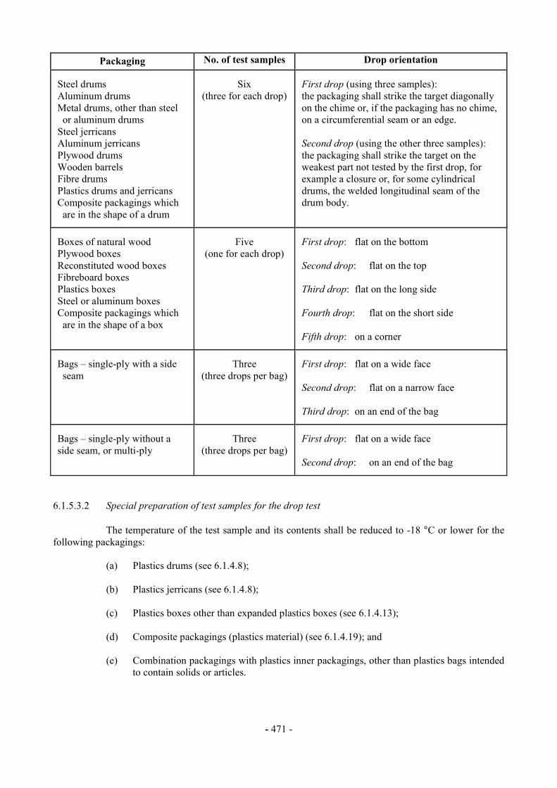
6.1.5.2 Preparation of packagings for testing 6.1.5.2.1 Tests shall be carried out on packagings prepared as for transport including, with respect to combination packagings, the inner packagings used. Inner or single receptacles or packagings shall be filled to not less than 98% of their maximum capacity for liquids or 95% for solids. For combination packagings where the inner packaging is designed to carry liquids and solids, separate testing is required for both liquid and solid contents. The substances or articles to be transported in the packagings may be replaced by other substances or articles except where this would invalidate the results of the tests. For solids, when another substance is used it shall have the same physical characteristics (mass, grain size, etc.) as the substance to be carried. It is permissible to use additives, such as bags of lead shot, to achieve the requisite total package mass, so long as they are placed so that the test results are not affected. 6.1.5.2.2 In the drop tests for liquids, when another substance is used, it shall be of similar relative density and viscosity to those of the substance being transported. Water may also be used for the liquid drop test under the conditions in 6.1.5.3.4. 6.1.5.2.3 Paper or fibreboard packagings shall be conditioned for at least 24 hours in an atmosphere having a controlled temperature and relative humidity (r.h.). There are three options, one of which shall be chosen. The preferred atmosphere is 23 " 2 °C and 50% " 2% r.h. The two other options are 20 " 2 °C and 65% " 2% r.h. or 27 " 2 °C and 65% " 2% r.h. NOTE: Average values shall fall within these limits. Short-term fluctuations and measurement limitations may cause individual measurements to vary by up to " 5% relative humidity without significant impairment of test reproducibility. 6.1.5.2.4 Bung-type barrels made of natural wood shall be left filled with water for at least 24 hours before the tests. 6.1.5.2.5 Additional steps shall be taken to ascertain that the plastics material used in the manufacture of plastics drums, plastics jerricans and composite packagings (plastics material) intended to contain liquids complies with the requirements in 6.1.1.2, 6.1.4.8.1 and 6.1.4.8.4. This may be done, for example, by submitting sample receptacles or packagings to a preliminary test extending over a long period, for example six months, during which the samples would remain filled with the substances they are intended to contain, and after which the samples shall be submitted to the applicable tests listed in 6.1.5.3, 6.1.5.4, 6.1.5.5 and 6.1.5.6. For substances which may cause stress-cracking or weakening in plastics drums or jerricans, the sample, filled with the substance or another substance that is known to have at least as severe a stress-cracking influence on the plastics material in question, shall be subjected to a superimposed load equivalent to the total mass of identical packages which might be stacked on it during transport. The minimum height of the stack including the test sample shall be 3 metres. 6.1.5.3 Drop test 6.1.5.3.l Number of test samples (per design type and manufacturer) and drop orientation
For other than flat drops the centre of gravity shall be vertically over the point of impact. Where more than one orientation is possible for a given drop test, the orientation most likely to
result in failure of the packaging shall be used.
- 471 -
Packaging No. of test samples Drop orientation Steel drums Aluminum drums Metal drums, other than steel or aluminum drums Steel jerricans Aluminum jerricans Plywood drums Wooden barrels Fibre drums Plastics drums and jerricans Composite packagings which are in the shape of a drum
Six
(three for each drop)
First drop (using three samples): the packaging shall strike the target diagonally on the chime or, if the packaging has no chime, on a circumferential seam or an edge. Second drop (using the other three samples): the packaging shall strike the target on the weakest part not tested by the first drop, for example a closure or, for some cylindrical drums, the welded longitudinal seam of the drum body.
Boxes of natural wood Plywood boxes Reconstituted wood boxes Fibreboard boxes Plastics boxes Steel or aluminum boxes Composite packagings which are in the shape of a box
Five
(one for each drop)
First drop: flat on the bottom Second drop: flat on the top Third drop: flat on the long side Fourth drop: flat on the short side Fifth drop: on a corner
Bags – single-ply with a side seam
Three
(three drops per bag)
First drop: flat on a wide face Second drop: flat on a narrow face Third drop: on an end of the bag
Bags – single-ply without a side seam, or multi-ply
Three
(three drops per bag)
First drop: flat on a wide face Second drop: on an end of the bag
6.1.5.3.2 Special preparation of test samples for the drop test
The temperature of the test sample and its contents shall be reduced to -18 °C or lower for the following packagings:
(a) Plastics drums (see 6.1.4.8); (b) Plastics jerricans (see 6.1.4.8);
(c) Plastics boxes other than expanded plastics boxes (see 6.1.4.13);
(d) Composite packagings (plastics material) (see 6.1.4.19); and
(e) Combination packagings with plastics inner packagings, other than plastics bags intended
to contain solids or articles.
- 472 -
Where test samples are prepared in this way, the conditioning in 6.1.5.2.3 may be waived. Test liquids shall be kept in the liquid state by the addition of anti-freeze if necessary. 6.1.5.3.3 Target
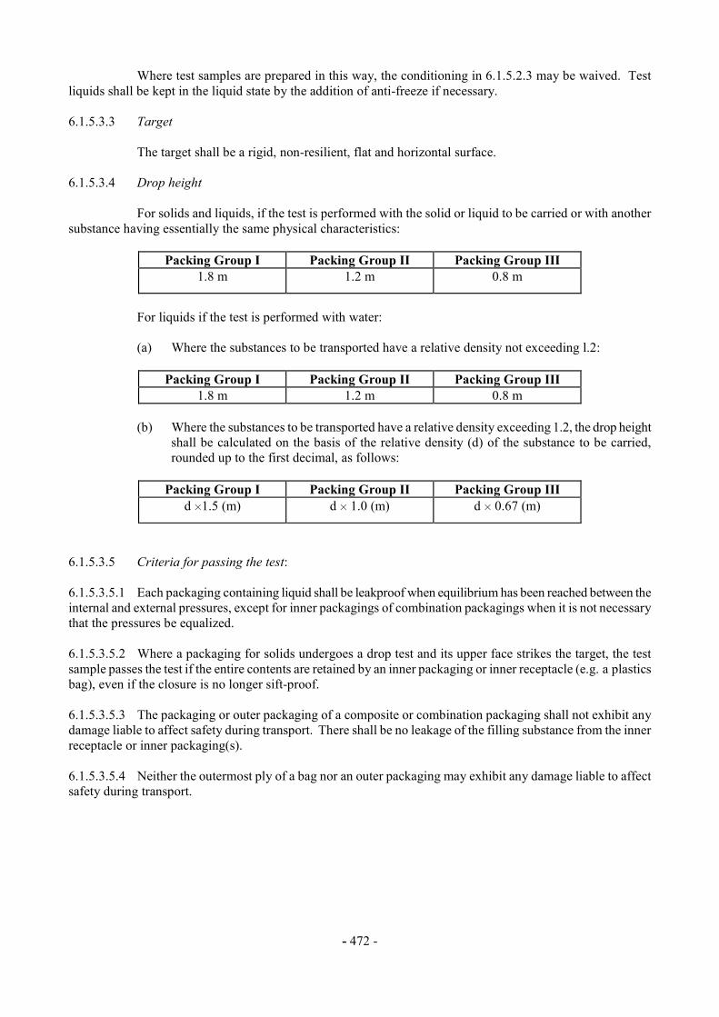
The target shall be a rigid, non-resilient, flat and horizontal surface. 6.1.5.3.4 Drop height
For solids and liquids, if the test is performed with the solid or liquid to be carried or with another substance having essentially the same physical characteristics:
Packing Group I Packing Group II Packing Group III 1.8 m 1.2 m 0.8 m
For liquids if the test is performed with water:
(a) Where the substances to be transported have a relative density not exceeding l.2:
Packing Group I Packing Group II Packing Group III
1.8 m 1.2 m 0.8 m (b) Where the substances to be transported have a relative density exceeding 1.2, the drop height
shall be calculated on the basis of the relative density (d) of the substance to be carried, rounded up to the first decimal, as follows:
Packing Group I Packing Group II Packing Group III
d H1.5 (m) d H 1.0 (m) d H 0.67 (m)
6.1.5.3.5 Criteria for passing the test: 6.1.5.3.5.1 Each packaging containing liquid shall be leakproof when equilibrium has been reached between the internal and external pressures, except for inner packagings of combination packagings when it is not necessary that the pressures be equalized. 6.1.5.3.5.2 Where a packaging for solids undergoes a drop test and its upper face strikes the target, the test sample passes the test if the entire contents are retained by an inner packaging or inner receptacle (e.g. a plastics bag), even if the closure is no longer sift-proof. 6.1.5.3.5.3 The packaging or outer packaging of a composite or combination packaging shall not exhibit any damage liable to affect safety during transport. There shall be no leakage of the filling substance from the inner receptacle or inner packaging(s). 6.1.5.3.5.4 Neither the outermost ply of a bag nor an outer packaging may exhibit any damage liable to affect safety during transport.
- 473 -
6.1.5.3.5.5 A slight discharge from the closure(s) upon impact is not considered to be a failure of the packaging provided that no further leakage occurs. 6.1.5.3.5.6 No rupture is permitted in packagings for goods of Class 1 which would permit the spillage of loose explosive substances or articles from the outer packaging. 6.1.5.4 Leakproofness test
The leakproofness test shall be performed on all design types of packagings intended to contain liquids; however, this test is not required for the inner packagings of combination packagings. 6.1.5.4.1 Number of test samples: three test samples per design type and manufacturer. 6.1.5.4.2 Special preparation of test samples for the test: either vented closures shall be replaced by similar non-vented closures or the vent shall be sealed. 6.1.5.4.3 Test method and pressure to be applied: the packagings including their closures shall be restrained under water for 5 minutes while an internal air pressure is applied, the method of restraint shall not affect the results of the test.
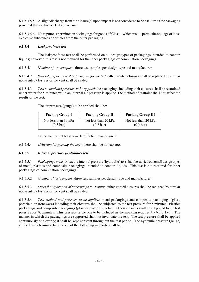
The air pressure (gauge) to be applied shall be:
Packing Group I Packing Group II Packing Group III Not less than 30 kPa
(0.3 bar) Not less than 20 kPa
(0.2 bar) Not less than 20 kPa
(0.2 bar)
Other methods at least equally effective may be used.
6.1.5.4.4 Criterion for passing the test: there shall be no leakage. 6.1.5.5 Internal pressure (hydraulic) test 6.1.5.5.1 Packagings to be tested: the internal pressure (hydraulic) test shall be carried out on all design types of metal, plastics and composite packagings intended to contain liquids. This test is not required for inner packagings of combination packagings. 6.1.5.5.2 Number of test samples: three test samples per design type and manufacturer. 6.1.5.5.3 Special preparation of packagings for testing: either vented closures shall be replaced by similar non-vented closures or the vent shall be sealed. 6.1.5.5.4 Test method and pressure to be applied: metal packagings and composite packagings (glass, porcelain or stoneware) including their closures shall be subjected to the test pressure for 5 minutes. Plastics packagings and composite packagings (plastics material) including their closures shall be subjected to the test pressure for 30 minutes. This pressure is the one to be included in the marking required by 6.1.3.1 (d). The manner in which the packagings are supported shall not invalidate the test. The test pressure shall be applied continuously and evenly; it shall be kept constant throughout the test period. The hydraulic pressure (gauge) applied, as determined by any one of the following methods, shall be:
- 474 -
(a) Not less than the total gauge pressure measured in the packaging (i.e. the vapour pressure of the filling liquid and the partial pressure of the air or other inert gases, minus 100 kPa) at 55 °C, multiplied by a safety factor of 1.5; this total gauge pressure shall be determined on the basis of a maximum degree of filling in accordance with 4.1.1.4 and a filling temperature of l5 °C;
(b) Not less than 1.75 times the vapour pressure at 50 °C of the liquid to be transported, minus
100 kPa but with a minimum test pressure of 100 kPa;
(c) Not less than 1.5 times the vapour pressure at 55 °C of the liquid to be transported, minus 100 kPa but with a minimum test pressure of 100 kPa.
6.1.5.5.5 In addition, packagings intended to contain liquids of Packing Group I shall be tested to a minimum test pressure of 250 kPa (gauge) for a test period of 5 or 30 minutes depending upon the material of construction of the packaging. 6.1.5.5.6 The special requirements for air transport, including minimum test pressures, may not be covered in 6.1.5.5.4. 6.1.5.5.7 Criterion for passing the test: no packaging may leak. 6.1.5.6 Stacking test
All design types of packagings other than bags are subject to a stacking test. 6.1.5.6.1 Number of test samples: three test samples per design type and manufacturer. 6.1.5.6.2 Test method: the test sample shall be subjected to a force applied to the top surface of the test sample equivalent to the total weight of identical packages which might be stacked on it during transport; where the contents of the test sample are liquids with relative density different from that of the liquid to be transported, the force shall be calculated in relation to the latter. The minimum height of the stack including the test sample shall be 3 meters. The duration of the test shall be 24 hours except that plastics drums, jerricans, and composite packagings 6HH1 and 6HH2 intended for liquids shall be subjected to the stacking test for a period of 28 days at a temperature of not less than 40 °C. 6.1.5.6.3 Criterion for passing the test: no test sample may leak. In composite packagings or combination packagings, there shall be no leakage of the filling substance from the inner receptacle or inner packaging. No test sample may show any deterioration which could adversely affect transport safety or any distortion liable to reduce its strength or cause instability in stacks of packages. Plastics packagings shall be cooled to ambient temperature before the assessment. 6.1.5.7 Cooperage test for bung type wooden barrels 6.1.5.7.1 Number of samples: one barrel. 6.1.5.7.2 Method of testing: remove all hoops above the bilge of an empty barrel at least two days old. 6.1.5.7.3 Criterion for passing the test: the diameter of the cross-section of the upper part of the barrel shall not increase by more than 10%.
- 475 -
6.1.5.8 Test Report 6.1.5.8.1 A test report containing at least the following particulars shall be drawn up and shall be available to the users of the packaging:
1. Name and address of the test facility; 2. Name and address of applicant (where appropriate); 3. A unique test report identification; 4. Date of the test report; 5. Manufacturer of the packaging; 6. Description of the packaging design type (e.g. dimensions, materials, closures, thickness,
etc.), including method of manufacture (e.g. blow moulding) and which may include drawing(s) and/or photograph(s);
7. Maximum capacity; 8. Characteristics of test contents, e.g. viscosity and relative density for liquids and particle size
for solids; 9. Test descriptions and results; 10. The test report shall be signed with the name and status of the signatory.
6.1.5.8.2 The test report shall contain statements that the packaging prepared as for transport was tested in accordance with the appropriate requirements of this Chapter and that the use of other packaging methods or components may render it invalid. A copy of the test report shall be available to the competent authority.


- 477 -
CHAPTER 6.2
REQUIREMENTS FOR THE CONSTRUCTION AND TESTING OF PRESSURE RECEPTACLES, AEROSOL DISPENSERS AND SMALL RECEPTACLES
CONTAINING GAS (GAS CARTRIDGES) 6.2.1 General requirements NOTE: For aerosol dispensers and small receptacles containing gas (gas cartridges) see 6.2.4. 6.2.1.1 Design and construction 6.2.1.1.1 Pressure receptacles and their closures shall be designed, manufactured, tested and equipped in such a way as to withstand all conditions to which they will be subjected during normal conditions of transport. 6.2.1.1.2 In recognition of scientific and technological advances, and recognizing that pressure receptacles other than those that are marked with a UN certification marking may be used on a national or regional basis, pressure receptacles conforming to requirements other than those specified in these regulations may be used if approved by the competent authorities in the countries of transport and use. 6.2.1.1.3 Any additional thickness used for the purpose of providing a corrosion allowance shall not be taken into consideration in calculating the thickness of the walls. In no case shall the minimum wall thickness be less than that specified in the design and construction technical standards. 6.2.1.1.4 For welded pressure receptacles, only metals of weldable quality shall be used. 6.2.1.1.5 The following requirements apply to the construction of closed cryogenic pressure receptacles for refrigerated liquefied gases:
(a) The mechanical properties of the metal used shall be established for each pressure receptacle at the initial inspection, including the impact strength and the bending coefficient;
(b) The pressure receptacles shall be thermally insulated. The thermal insulation shall be
protected against impact by means of continuous sheathing. If the space between the pressure receptacle and the sheathing is evacuated of air (vacuum-insulation), the protective sheathing shall be designed to withstand without permanent deformation an external pressure of at least 100 kPa (1 bar). If the sheathing is so closed as to be gas-tight (e.g. in the case of vacuum-insulation), a device shall be provided to prevent any dangerous pressure from developing in the insulating layer in the event of inadequate gas-tightness of the pressure receptacle or its fittings. The device shall prevent moisture from penetrating into the insulation.
6.2.1.1.6 The test pressure of cylinders, tubes, pressure drums and bundles of cylinders shall be in accordance with packing instruction P200. The test pressure for closed cryogenic receptacles shall be in accordance with packing instruction P203. 6.2.1.1.7 Pressure receptacles assembled in bundles shall be structurally supported and held together as a unit. Pressure receptacles shall be secured in a manner that prevents movement in relation to the structural assembly and movement that would result in the concentration of harmful local stresses. Manifolds shall be designed such that they are protected from impact. For Division 2.3 liquefied gases, means shall be provided to ensure that each pressure receptacle can be separately charged and that no interchange of pressure receptacle contents can occur during transport.

- 478 -
6.2.1.2 Materials 6.2.1.2.1 Construction materials of pressure receptacles and their closures which are in direct contact with dangerous goods shall not be affected or weakened by the dangerous goods intended and shall not cause a dangerous effect e.g. catalysing a reaction or reacting with the dangerous goods. 6.2.1.2.2 Pressure receptacles and their closures shall be made of the materials specified in the design and construction technical standards and the applicable packing instruction for the substances intended for transport in the pressure receptacle. The materials shall be resistant to brittle fracture and to stress corrosion cracking as indicated in the design and construction technical standards. 6.2.1.3 Service equipment 6.2.1.3.1 Except for pressure relief devices, valves, piping, fittings and other equipment subjected to pressure, shall be designed and constructed to withstand at least 1.5 times the test pressure of the pressure receptacles. 6.2.1.3.2 Service equipment shall be configured or designed to prevent damage that could result in the release of the pressure receptacle contents during normal conditions of handling and transport. Manifold piping leading to shut-off valves shall be sufficiently flexible to protect the valves and the piping from shearing or releasing the pressure receptacle contents. The filling and discharge valves and any protective caps shall be capable of being secured against unintended opening. Valves shall be protected as specified in 4.1.6.1.7. 6.2.1.3.3 Pressure receptacles which are not capable of being handled manually or rolled, shall be fitted with devices (skids, rings, straps) ensuring that they can be safely handled by mechanical means and so arranged as not to impair the strength of, nor cause undue stresses, in the pressure receptacle. 6.2.1.3.4 Individual pressure receptacles shall be equipped with approved pressure relief devices as required in P200(1) or as specified by the country of use. When fitted, pressure relief devices on manifolded horizontal pressure receptacles filled with flammable gas shall be arranged to discharge freely to the open air in such a manner as to prevent any impingement of escaping gas upon the pressure receptacles under normal conditions of transport. [6.2.1.3.5 Reserved for Cryogenic receptacles] 6.2.1.3.6 Pressure receptacles whose filling is measured by volume shall be provided with a level indicator. 6.2.1.4 Initial inspection and test 6.2.1.4.1 New pressure receptacles shall be subjected to testing and inspection during and after manufacture in accordance with the applicable design standards including the following: On an adequate sample of pressure receptacles: (a) Testing of the mechanical characteristics of the material of construction; (b) Verification of the minimum wall thickness;
(c) Verification of the homogeneity of the material for each manufacturing batch, and inspection of the external and internal conditions of the pressure receptacles;
(d) Inspection of the neck threads;
- 479 -
(e) Verification of the conformance with the design standard; For all pressure receptacles:
(f) A hydraulic pressure test. Pressure receptacles shall withstand the test pressure without expansion greater than that allowed in the design specification;
NOTE: With the agreement of the inspection body, the hydraulic pressure test may be
replaced by a test using a gas, where such an operation does not entail any danger.
(g) Inspection and assessment of manufacturing defects and either repairing them or rendering the pressure receptacles unserviceable.
(h) An inspection of the markings on the pressure receptacles; (i) In addition, pressure receptacles intended for the transport of UN 1001 acetylene, dissolved,
and UN 3374 acetylene, solvent free, shall be inspected to ensure proper installation and condition of the porous material and the quantity of solvent.
6.2.1.5 Periodic inspection and test 6.2.1.5.1 Refillable pressure receptacles, other than cryogenic receptacles, shall be subjected to periodic inspections and tests under the supervision of an inspection body, in accordance with the following: (a) Check of the external conditions of the pressure receptacle and verification of the equipment
and the external markings;
(b) Check of the internal conditions of the pressure receptacle (e.g. by weighing, internal inspection, checks of wall thickness);
(c) Checking of the neck threads; (d) A hydraulic pressure test and, if necessary, verification of the characteristics of the material
by suitable tests.
NOTE 1: With the agreement of the inspection body, the hydraulic pressure test may be replaced by a test using a gas, where such an operation does not entail any danger.
NOTE 2: With the agreement of the competent authority, the hydraulic pressure test of
cylinders and tubes may be replaced by an equivalent method based on acoustic emission or ultrasound.
6.2.1.5.2 For pressure receptacles intended for the transport of UN 1001 acetylene, dissolved, UN 3374 acetylene, solvent free, only the external condition (corrosion, deformation) and the condition of the porous mass (loosening, settlement) shall be required to be examined. 6.2.1.5.3 Closed cryogenic pressure receptacles shall be inspected to verify external conditions, condition and operation of pressure relief devices and the legibility and adequacy of the markings. The thermal insulation need not be removed.
- 480 -
6.2.1.6 Approval of pressure receptacles 6.2.1.6.1 The conformity of pressure receptacles shall be assessed at time of manufacture as required by the competent authority. Pressure receptacles shall be inspected, tested and approved by an inspection body. The technical documentation shall include full specifications on design and construction, and full documentation on the manufacturing and testing. 6.2.1.6.2 Quality assurance systems shall conform to the requirements of the competent authority. 6.2.1.7 Requirements for manufacturers 6.2.1.7.1 The manufacturer shall be technically able and shall possess all resources required for the satisfactory manufacture of pressure receptacles; this relates in particular to qualified personnel: (a) to supervise the entire manufacturing process; (b) to carry out joining of materials; and (c) to carry out the relevant tests. 6.2.1.7.2 The proficiency test of a manufacturer shall in all instances be carried out by an inspection body approved by the competent authority of the country of approval. 6.2.1.8 Requirements for inspection bodies 6.2.1.8.1 Inspection bodies shall be independent from manufacturing enterprises and competent to perform the tests, inspections and approvals required. 6.2.2 Requirements for UN certified pressure receptacles In addition to the general requirements of section 6.2.1, UN certified pressure receptacles shall comply with the requirements of this section, including the standards, as applicable. NOTE: With the agreement of the competent authority, more recently published versions of the standards, if available, may be used. 6.2.2.1 Design, construction and initial inspection and test 6.2.2.1.1 The following standards apply for the design, construction, and initial inspection and test of UN certified cylinders:
ISO 9809-1:1999 Gas cylinders – Refillable seamless steel gas cylinders - Design, construction and testing - Part 1: Quenched and tempered steel cylinders with tensile strength less than 1100 Mpa NOTE: The note concerning the F factor in section 7.3 of this standard shall not be applied for UN certified cylinders.
ISO 9809-2:2000
Gas cylinders – Refillable seamless steel gas cylinders - Design, construction and testing - Part 2: Quenched and tempered steel cylinders with tensile strength greater than or equal to 1100 MPa
ISO 9809-3:2000 Gas cylinders – Refillable seamless steel gas cylinders - Design, construction and testing - Part 3: Normalized steel cylinders
- 481 -
ISO 7866:1999 Gas cylinders – Refillable seamless aluminum alloy gas cylinders – Design, construction and testing NOTE: The note concerning the F factor in section 7.2 of this standard shall not be applied for UN certified cylinders. Aluminum alloy 6351A – T6 or equivalent shall not be authorized.
ISO 11118:1999 Gas cylinders – Non-refillable metallic gas cylinders - Specification and test methods
6.2.2.1.2 The following standards apply for the design, construction, and initial inspection and test of UN certified tubes:
ISO 11120:1999 Gas cylinders – Refillable seamless steel tubes for compressed gas transport, of water capacity between 150 l and 3000 l – Design, construction and testing NOTE: The note concerning the F factor in section 7.1 of this standard shall not be applied for UN certified tubes
6.2.2.1.3 The following standards apply for the design, construction and initial inspection and test of UN certified acetylene cylinders: For the cylinder shell:
ISO 9809-1:1999 Gas cylinders – Refillable seamless steel gas cylinders - Design, construction and testing – Part 1: Quenched and tempered steel cylinders with tensile strength less than 1100 MPa NOTE: The note concerning the F factor in section 7.3 of this standard shall not be applied for UN certified cylinders.
ISO 9809-3:2000 Gas cylinders – Refillable seamless steel gas cylinders - Design, construction and testing – Part 3: Normalized steel cylinders
ISO 7866:1999 Gas cylinders – Refillable seamless aluminum alloy gas cylinders – Design, construction and testing NOTE: The note concerning the F factor in section 7.2 of this standard shall not be applied for UN certified cylinders. Aluminum alloy 6351A – T6 or equivalent shall not be authorized.
ISO 11118:1999 Gas cylinders – Non-refillable metallic gas cylinders - Specification and test methods
For the porous mass in the cylinder:
ISO 3807-1:2000 Cylinders for acetylene – Basic requirements - Part 1: Cylinders
without fusible plugs ISO 3807-2:2000 Cylinders for acetylene – Basic requirements - Part 2: Cylinders
with fusible plugs

- 482 -
6.2.2.2 Materials In addition to the material requirements specified in the pressure receptacle design and construction standards, and any restrictions specified in the applicable packing instruction for the gas(es) to be transported (e.g. packing instruction P200), the following standards apply to material compatibility:
ISO 11114-1:1997 Transportable gas cylinders – Compatibility of cylinder and
valve materials with gas contents – Part 1: Metallic materials ISO 11114-2:2000 Transportable gas cylinders – Compatibility of cylinder and
valve materials with gas contents – Part 2: Non-metallic materials
6.2.2.3 Service equipment The following standards apply to closures and their protection:
ISO 11117:1998 Gas cylinders - Valve protection caps and valve guards for industrial and medical gas cylinders- Design, construction and tests
ISO 10297:1999 Gas cylinders –Refillable gas cylinder valves - Specification and type testing
6.2.2.4 Periodic inspection and test The following standards apply to the periodic inspection and testing of UN certified cylinders:
ISO 6406:1992 Periodic inspection and testing of seamless steel gas cylinders ISO 10461:1993 Seamless aluminum - alloy gas cylinders - Periodic inspection
and testing ISO 10462:1994
Cylinders for dissolved acetylene – Periodic inspection and maintenance
6.2.2.5 Conformity assessment system and approval of pressure receptacles 6.2.2.5.1 Definitions For the purposes of this section: Conformity assessment system means a system for competent authority approval of a manufacturer, by pressure receptacle design type approval, approval of manufacturer's quality system and approval of inspection bodies; Design type means a pressure receptacle design as specified by a particular pressure receptacle standard; Verify means confirm by examination or provision of objective evidence that specified requirements have been fulfilled; 6.2.2.5.2 General requirements Competent Authority 6.2.2.5.2.1 The competent authority that approves the pressure receptacle shall approve the conformity assessment system for the purpose of ensuring that pressure receptacles conform to the requirements of these regulations. In instances where the competent authority that approves a pressure receptacle is not the

- 483 -
competent authority in the country of manufacture, the marks of the approval country and the country of manufacture shall be indicated in the pressure receptacle marking (see 6.2.2.6 and 6.2.2.7). The competent authority of the country of approval shall supply, upon request, evidence demonstrating compliance to this conformity assessment system to its counterpart in a country of use. 6.2.2.5.2.2 The competent authority may delegate its functions in this conformity assessment system in whole or in part. 6.2.2.5.2.3 The competent authority shall ensure that a current list of approved inspection bodies and their identity marks and approved manufacturers and their identity marks is available. Inspection body 6.2.2.5.2.4 The inspection body shall be approved by the competent authority as an inspector of pressure receptacles and shall: (a) have a staff with an organisational structure, capable, trained, competent, and skilled, to
satisfactorily perform its technical functions; (b) have access to suitable and adequate facilities and equipment; (c) operate in an impartial manner and be free from any influence which could prevent it from
doing so; (d) ensure confidentiality of the commercial and proprietary activities of the manufacturer and
other bodies; (e) maintain clear demarcation between actual inspection body functions and unrelated
functions; (f) operate a documented quality system; (g) ensure that the tests and inspections specified in the relevant pressure receptacle standard and
these regulations are performed; and (h) maintain an effective and appropriate report and record system in accordance with 6.2.2.5.6.
6.2.2.5.2.5 The inspection body shall perform design type approval, pressure receptacle production testing and inspection, and certification to verify conformity with the relevant pressure receptacle standard (see 6.2.2.5.4 and 6.2.2.5.5). Manufacturer 6.2.2.5.2.6 The manufacturer shall:
(a) operate a documented quality system in accordance with 6.2.2.5.3;
(b) apply for design type approvals in accordance with 6.2.2.5.4;
(c) select an inspection body from the list of approved inspection bodies maintained by the competent authority in the country of approval; and
(d) maintain records in accordance with 6.2.2.5.6.
- 484 -
Testing laboratory 6.2.2.5.2.7 The testing laboratory shall have: (a) staff with an organisational structure, sufficient in number, competence, and skill; and (b) suitable and adequate facilities and equipment to perform the tests required by the
manufacturing standard to the satisfaction of the inspection body. 6.2.2.5.3 Manufacturer's quality system 6.2.2.5.3.1 The quality system shall contain all the elements, requirements, and provisions adopted by the manufacturer. It shall be documented in a systematic and orderly manner in the form of written policies, procedures and instructions. The contents shall in particular include adequate descriptions of: (a) the organisational structure, responsibilities, and power of the management with regard to
design and product quality; (b) the design control and design verification techniques, processes, and systematic actions
that will be used when designing the pressure receptacles; (c) the relevant pressure receptacle manufacturing, quality control, quality assurance, and
process operation instructions that will be used; (d) quality records, such as inspection reports, test data, and calibration data; (e) management reviews to ensure the effective operation of the quality system arising from
the audits in accordance with 6.2.2.5.3.2; (f) the process describing how customer requirements are met; (g) the process for control of documents and their revision;
(h) the means for control of non-conforming pressure receptacles, purchased components, in - process and final materials; and
(i) training programmes for relevant personnel.
6.2.2.5.3.2 Audit of the quality system The quality system shall be initially assessed to determine whether it meets the requirements in 6.2.2.5.3.1 to the satisfaction of the competent authority. The manufacturer shall be notified of the results of the audit. The notification shall contain the conclusions of the audit and any corrective actions required. Periodic audits shall be carried out, to the satisfaction of the competent authority, to ensure that the manufacturer maintains and applies the quality system. Reports of the periodic audits shall be provided to the manufacturer.
- 485 -
6.2.2.5.3.3 Maintenance of the quality system The manufacturer shall maintain the quality system as approved in order that it remains adequate and efficient.The manufacturer shall notify the competent authority that approved the quality system, of any intended changes. The proposed changes shall be evaluated in order to determine whether the amended quality system will still satisfy the requirements in 6.2.2.5.3.1. 6.2.2.5.4 Approval process Initial design type approval 6.2.2.5.4.1 The initial design type approval shall consist of approval of the manufacturer's quality system and approval of the pressure receptacle design to be produced. An application for an initial design type approval shall encompass the requirements of 6.2.2.5.4.2 to 6.2.2.5.4.6 and 6.2.2.5.4.9. 6.2.2.5.4.2 A manufacturer desiring to produce pressure receptacles in accordance with a pressure receptacle standard and these regulations shall apply for, obtain, and retain a Design Type Approval Certificate issued by the competent authority in the country of approval for at least one pressure receptacle design type in accordance with the procedure given in 6.2.2.5.4.9. This written approval shall, on request, be submitted to the competent authority of the country of use. 6.2.2.5.4.3 An application shall be made for each manufacturing facility and shall include: (a) the name and registered address of the manufacturer and in addition, if the application is
submitted by an authorised representative, its name and address; (b) the address of the manufacturing facility (if different from the above); (c) the name and title of the person(s) responsible for the quality system; (d) the designation of the pressure receptacle and the relevant pressure receptacle standard;
(e) details of any refusal of approval of a similar application by any other competent authority; (f) the identity of the inspection body for design type approval; (g) documentation on the manufacturing facility as specified under 6.2.2.5.3.1; and (h) the technical documentation required for design type approval, which shall enable
verification of the conformity of the pressure receptacles with the requirements of the relevant pressure receptacle design standard. The technical documentation shall cover the design and method of manufacture and shall contain, as far as is relevant for assessment, at least the following:
(i) pressure receptacle design standard, design and manufacturing drawings, showing
components and subassemblies, if any; (ii) descriptions and explanations necessary for the understanding of the drawings and
intended use of the pressure receptacles; (iii) a list of the standards necessary to fully define the manufacturing process; (iv) design calculations and material specifications; and
- 486 -
(v) design type approval test reports, describing the results of examinations and tests carried out in accordance with 6.2.2.5.4.9.
6.2.2.5.4.4 An initial audit in accordance with 6.2.2.5.3.2 shall be performed to the satisfaction of the competent authority. 6.2.2.5.4.5 If the manufacturer is denied approval, the competent authority shall provide written detailed reasons for such denial. 6.2.2.5.4.6 Following approval, changes to the information submitted under 6.2.2.5.4.2 relating to the initial approval shall be provided to the competent authority. Subsequent design type approvals 6.2.2.5.4.7 An application for a subsequent design type approval shall encompass the requirements of 6.2.2.5.4.8 and 6.2.2.5.4.9, provided a manufacturer is in the possession of an initial design type approval. In such a case, the manufacturer's quality system according to 6.2.2.5.3 shall have been approved during the initial design type approval and shall be applicable for the new design. 6.2.2.5.4.8 The application shall include: (a) the name and address of the manufacturer and in addition, if the application is submitted by
an authorised representative, its name and address; (b) details of any refusal of approval of a similar application by any other competent authority; (c) evidence that initial design type approval has been granted; and (d) the technical documentation, as described in 6.2.2.5.4.3 (h). Procedure for design type approval 6.2.2.5.4.9 The inspection body shall: (a) examine the technical documentation to verify that: (i) the design is in accordance with the relevant provisions of the standard, and (ii) the prototype lot has been manufactured in conformity with the technical
documentation and is representative of the design; (b) verify that the production inspections have been carried out as required in accordance with
6.2.2.5.5; (c) select pressure receptacles from a prototype production lot and supervise the tests of these
pressure receptacles as required for design type approval; (d) perform or have performed the examinations and tests specified in the pressure receptacle
standard to determine that: (i) the standard has been applied and fulfilled, and (ii) the procedures adopted by the manufacturer meet the requirements of the standard;
and

- 487 -
(e) ensure that the various type approval examinations and tests are correctly and competently carried out.
After prototype testing has been carried out with satisfactory results and all applicable requirements of 6.2.2.5.4 have been satisfied, a Design Type Approval Certificate shall be issued, which shall include the name and address of the manufacturer, results and conclusions of the examination, and the necessary data for identification of the design type. If the manufacturer is denied a design type certification, the competent authority shall provide written detailed reasons for such denial. 6.2.2.5.4.10 Modifications to approved design types The manufacturer shall inform the issuing competent authority of modifications to the approved design type as specified in the pressure receptacle standard. A subsequent design type approval shall be requested where such modifications constitute a new design according to the relevant pressure receptacle standard. This additional approval shall be given in the form of an amendment to the original Design Type Approval Certificate. 6.2.2.5.4.11 Upon request, the competent authority shall communicate to any other competent authority, information concerning design type approval, modifications of approvals and withdrawn approvals. 6.2.2.5.5 Production inspection and certification An inspection body, or its delegate, shall carry out the inspection and certification of each pressure receptacle. The inspection body selected by the manufacturer for inspection and testing during production may be different from the inspection body used for the design type approval testing. Where it can be demonstrated to the satisfaction of the inspection body that the manufacturer has trained competent inspectors, independent of the manufacturing operations, inspection may be performed by those inspectors. In such a case, the manufacturer shall maintain training records of the inspectors. The inspection body shall verify that the inspections by the manufacturer, and tests performed on those pressure receptacles, fully conform to the standard and the requirements of these regulations. Should non-conformance in conjunction with this inspection and testing be determined, the permission to have inspection performed by the manufacturer's inspectors may be withdrawn. The manufacturer shall, after approval by the inspection body, make a declaration of conformity with the certified design type. The application of the pressure receptacle certification marking shall be considered a declaration that the pressure receptacle complies with the applicable pressure receptacle standards and the requirements of this conformity assessment system and these regulations. The inspection body shall affix or delegate the manufacturer to affix the pressure receptacle certification marking and the registered mark of the inspection body to each approved pressure receptacle. A certificate of compliance, signed by the inspection body and the manufacturer, shall be issued before the pressure receptacles are filled. 6.2.2.5.6 Records Design type approval and certificate of compliance records shall be retained by the manufacturer and the inspection body for not less than 20 years.
- 488 -
6.2.2.6 Marking of UN certified refillable pressure receptacles UN certified refillable pressure receptacles shall be marked clearly and legibly with certification and gas or pressure receptacle specific marks. These marks shall be permanently affixed (e.g. stamped, engraved, or etched) on the pressure receptacle. The marks shall be on the shoulder, top end or neck of the pressure receptacle or on a permanently affixed component of the pressure receptacle (e.g. welded collar). Except for the "UN" mark, the minimum size of the marks shall be 5 mm for pressure receptacles with a diameter greater than or equal to 140 mm and 2.5 mm for pressure receptacles with a diameter less than 140 mm. The minimum size of the "UN" mark shall be 10 mm for pressure receptacles with a diameter greater than or equal to 140 mm and 5 mm for pressure receptacles with a diameter less than 140 mm. 6.2.2.6.1 The following certification marks shall be applied: (a) The UN packaging symbol
This symbol shall only be marked on pressure receptacles which conform to the requirements
of these regulations for UN certified pressure receptacles.
(b) The technical standard (e.g. ISO 9809-1) used for design, manufacture and testing;
(c) The character(s) identifying the country of approval as indicated by the distinguishing signs of motor vehicles in international traffic;
(d) The identity mark or stamp of the inspection body that is registered with the competent
authority of the country authorizing the marking; (e) The date of the initial inspection, the year (four digits) followed by the month (two digits)
separated by a slash (i.e. "/"). 6.2.2.6.2 The following operational marks shall be applied:
(f) The test pressure in bar, preceded by the letters "PH" and followed by the letters "BAR"; (g) The empty mass of the pressure receptacle including all permanently attached integral parts
(e.g. neck ring, foot ring, etc.) in kilograms, followed by the letters "KG". This mass shall not include the mass of valve, valve cap or valve guard, any coating, or porous mass for acetylene. The empty mass shall be expressed to three significant figures rounded up to the last digit. For cylinders of less than 1 kg, the mass shall be expressed to two significant figures rounded up to the last digit;
(h) The minimum guaranteed wall thickness of the pressure receptacle in millimetres followed
by the letters "MM". This mark is not required for pressure receptacles with a water capacity less than or equal to 1 litre or for composite cylinders;
(i) In the case of pressure receptacles intended for the transport of compressed gases, UN 1001
acetylene, dissolved, and UN 3374 acetylene, solvent free, the working pressure in bar, preceded by the letters "PW";
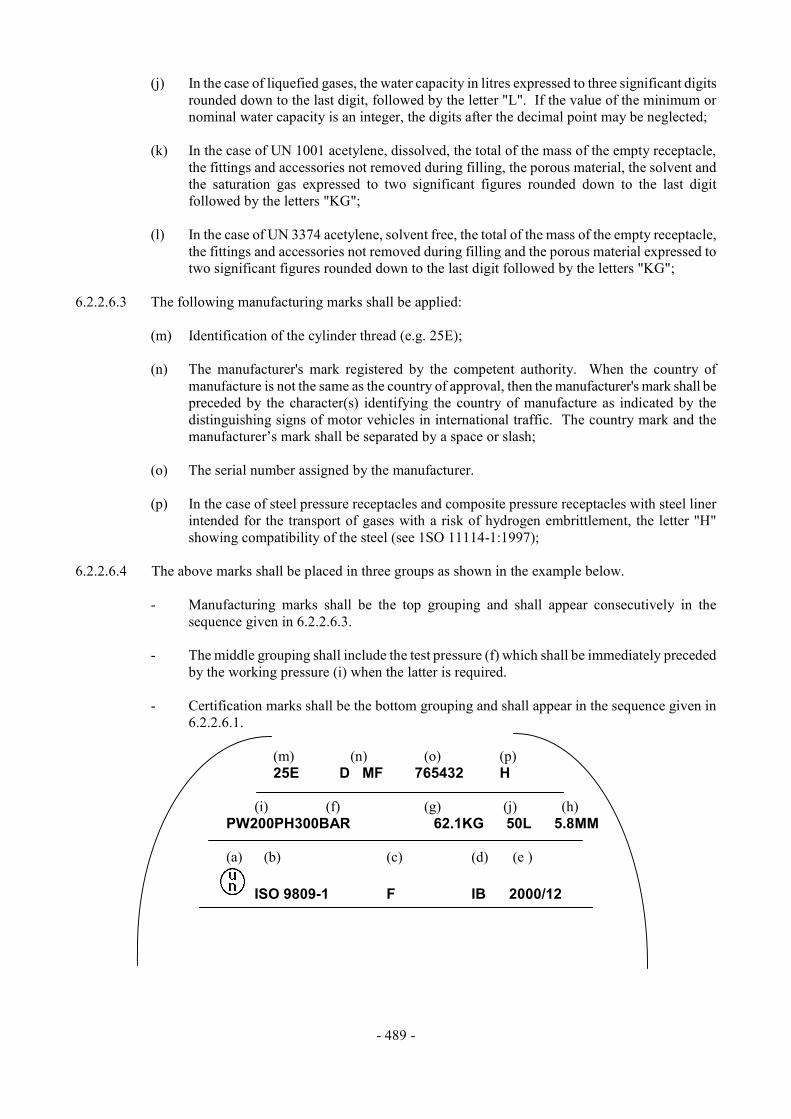
- 489 -
(j) In the case of liquefied gases, the water capacity in litres expressed to three significant digits rounded down to the last digit, followed by the letter "L". If the value of the minimum or nominal water capacity is an integer, the digits after the decimal point may be neglected;
(k) In the case of UN 1001 acetylene, dissolved, the total of the mass of the empty receptacle,
the fittings and accessories not removed during filling, the porous material, the solvent and the saturation gas expressed to two significant figures rounded down to the last digit followed by the letters "KG";
(l) In the case of UN 3374 acetylene, solvent free, the total of the mass of the empty receptacle,
the fittings and accessories not removed during filling and the porous material expressed to two significant figures rounded down to the last digit followed by the letters "KG";
6.2.2.6.3 The following manufacturing marks shall be applied:
(m) Identification of the cylinder thread (e.g. 25E); (n) The manufacturer's mark registered by the competent authority. When the country of
manufacture is not the same as the country of approval, then the manufacturer's mark shall be preceded by the character(s) identifying the country of manufacture as indicated by the distinguishing signs of motor vehicles in international traffic. The country mark and the manufacturer’s mark shall be separated by a space or slash;
(o) The serial number assigned by the manufacturer. (p) In the case of steel pressure receptacles and composite pressure receptacles with steel liner
intended for the transport of gases with a risk of hydrogen embrittlement, the letter "H" showing compatibility of the steel (see 1SO 11114-1:1997);
6.2.2.6.4 The above marks shall be placed in three groups as shown in the example below.
- Manufacturing marks shall be the top grouping and shall appear consecutively in the sequence given in 6.2.2.6.3.
- The middle grouping shall include the test pressure (f) which shall be immediately preceded
by the working pressure (i) when the latter is required. - Certification marks shall be the bottom grouping and shall appear in the sequence given in
6.2.2.6.1.
(m) (n) (o) (p) 25E D MF 765432 H (i) (f) (g) (j) (h) PW200PH300BAR 62.1KG 50L 5.8MM (a) (b) (c) (d) (e )
ISO 9809-1 F IB 2000/12

- 490 -
6.2.2.6.5 Other marks are allowed in areas other than the side wall, provided they are made in low stress areas and are not of a size and depth that will create harmful stress concentrations. Such marks shall not conflict with required marks. 6.2.2.6.6 In addition to the preceding marks, each refillable pressure receptacle shall be marked indicating the date (year and month) of the last periodic inspection and the registered mark of the inspection body authorized by the competent authority of the country of use. 6.2.2.7 Marking of UN certified non-refillable pressure receptacles UN certified non-refillable pressure receptacles shall be marked clearly and legibly with certification and gas or pressure receptacle specific marks. These marks shall be permanently affixed (e.g. stencilled, stamped, engraved, or etched) on the pressure receptacle. Except when stencilled, the marks shall be on the shoulder, top end or neck of the pressure receptacle or on a permanently affixed component of the pressure receptacle (e.g. welded collar). Except for the "UN" mark and the "DO NOT REFILL" mark, the minimum size of the marks shall be 5 mm for pressure receptacles with a diameter greater than or equal to 140 mm and 2.5 mm for pressure receptacles with a diameter less than 140 mm. The minimum size of the "UN" mark shall be 10 mm for pressure receptacles with a diameter greater than or equal to 140 mm and 5 mm for pressure receptacles with a diameter less than 140 mm. The minimum size of the "DO NOT REFILL" mark shall be 5 mm. 6.2.2.7.1 The marks listed in 6.2.2.6.1 to 6.2.2.6.3 shall be applied with the exception of (g), (h), and (m). The serial number (o) may be replaced by the batch number. In addition, the words "DO NOT REFILL" in letters of at least 5 mm in height are required. 6.2.2.7.2 The requirements of 6.2.2.6.4 shall apply. NOTE: Non-refillable pressure receptacles may, on account of their size, substitute this marking by a label (see 5.2.2.2.1.2). 6.2.2.7.3 Other marks are allowed provided they are made in low stress areas other than the side wall and are not of a size and depth that will create harmful stress concentrations. Such marks shall not conflict with required marks. 6.2.3 Requirements for non-UN certified pressure receptacles 6.2.3.1 Pressure receptacles not designed, constructed, inspected, tested and approved according to the requirements of 6.2.2 shall be designed, constructed, inspected, tested and approved in accordance with the provisions of a technical code recognised by the competent authority and the general requirements of 6.2.1. 6.2.3.2 Pressure receptacles designed, constructed, inspected, tested and approved under the provisions of this section shall not be marked with the UN packaging symbol. 6.2.3.3 For metallic cylinders, tubes, pressure drums and bundles of cylinders, the construction shall be such that the minimum burst ratio (burst pressure divided by test pressure) is:
1.50 for refillable pressure receptacles, 2.00 for non-refillable pressure receptacles.
6.2.3.4 Marking shall be in accordance with the requirements of the competent authority of the country of use.
- 491 -
6.2.4 Requirements for aerosol dispensers and small receptacles containing gas (gas cartridges) 6.2.4.1 Each receptacle shall be subjected to a test performed in a hot water bath; the temperature of the bath and the duration of the test shall be such that the internal pressure reaches that which would be reached at 55 °C (50 °C if the liquid phase does not exceed 95% of the capacity of the receptacle at 50 °C). If the contents are sensitive to heat or if the receptacles are made of plastics material which softens at this test temperature, the temperature of the bath shall be set at between 20 °C and 30 °C but, in addition, one receptacle in 2000 shall be tested at the higher temperature. 6.2.4.2 No leakage or permanent deformation of a receptacle may occur, except that a plastics receptacle may be deformed through softening provided that it does not leak.

- 493 -
CHAPTER 6.3
REQUIREMENTS FOR THE CONSTRUCTION AND TESTING OF PACKAGINGS FOR DIVISION 6.2 SUBSTANCES
6.3.1 General 6.3.1.1 A packaging that meets the requirements of this section and of 6.3.2 shall be marked with: (a) The United Nations packaging symbol; (b) The code designating the type of packaging according to the requirements of 6.1.2; (c) The text “CLASS 6.2”; (d) The last two digits of the year of manufacture of the packaging; (e) The state authorizing the allocation of the mark, indicated by the distinguishing sign for
motor vehicles in international traffic; (f) The name of the manufacturer or other identification of the packaging specified by the
competent authority; (g) For packagings meeting the requirements of 6.3.2.9, the letter "U", inserted immediately
following the marking required in (b) above. Each element of the marking applied in accordance with (a) to (g) shall be clearly separated, e.g. by a slash or space, so as to be easily identifiable. 6.3.1.2 Example of marking:
4G/CLASS 6.2/92 as in 6.3.1.1 (a), (b), (c) and (d) S/SP-9989-ERIKSSON as in 6.3.1.1 (e), (f)
6.3.1.3 Manufacturers and subsequent distributors of packagings shall provide information regarding procedures to be followed and a description of the types and dimensions of closures (including required gaskets) and any other components needed to ensure that packages as presented for transport are capable of passing the applicable performance tests of this Chapter. 6.3.2 Test requirements for packagings 6.3.2.1 Other than for packagings for live animals and organisms, samples of each packaging shall be prepared for testing as described in 6.3.2.2 and then subjected to the tests in 6.3.2.4 to 6.3.2.6. If the nature of the packaging makes it necessary, equivalent preparation and tests are permitted, provided that these may be demonstrated to be at least as effective. 6.3.2.2 Samples of each packaging shall be prepared as for transport except that a liquid or solid infectious substance shall be replaced by water or, where conditioning at -18 °C is specified, by water/antifreeze. Each primary receptacle shall be filled to 98% capacity.
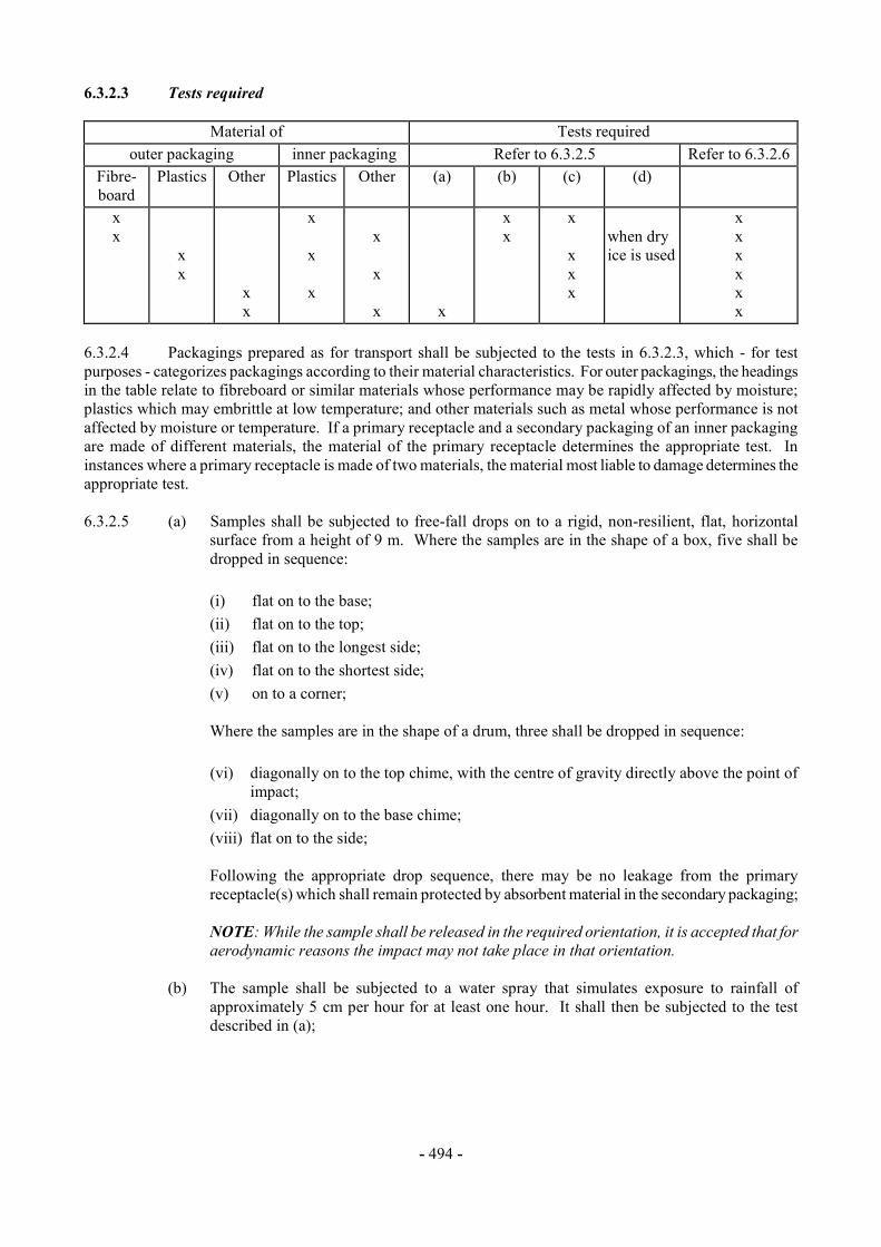
- 494 -
6.3.2.3 Tests required
Material of Tests required outer packaging inner packaging Refer to 6.3.2.5 Refer to 6.3.2.6
Fibre- board
Plastics Other Plastics Other (a) (b) (c) (d)
x x
x x
x x
x x x
x x x
x
x x
x x x x
when dry ice is used
x x x x x x
6.3.2.4 Packagings prepared as for transport shall be subjected to the tests in 6.3.2.3, which - for test purposes - categorizes packagings according to their material characteristics. For outer packagings, the headings in the table relate to fibreboard or similar materials whose performance may be rapidly affected by moisture; plastics which may embrittle at low temperature; and other materials such as metal whose performance is not affected by moisture or temperature. If a primary receptacle and a secondary packaging of an inner packaging are made of different materials, the material of the primary receptacle determines the appropriate test. In instances where a primary receptacle is made of two materials, the material most liable to damage determines the appropriate test. 6.3.2.5 (a) Samples shall be subjected to free-fall drops on to a rigid, non-resilient, flat, horizontal
surface from a height of 9 m. Where the samples are in the shape of a box, five shall be dropped in sequence:
(i) flat on to the base; (ii) flat on to the top; (iii) flat on to the longest side; (iv) flat on to the shortest side; (v) on to a corner;
Where the samples are in the shape of a drum, three shall be dropped in sequence:
(vi) diagonally on to the top chime, with the centre of gravity directly above the point of
impact; (vii) diagonally on to the base chime; (viii) flat on to the side;
Following the appropriate drop sequence, there may be no leakage from the primary receptacle(s) which shall remain protected by absorbent material in the secondary packaging;
NOTE: While the sample shall be released in the required orientation, it is accepted that for aerodynamic reasons the impact may not take place in that orientation.
(b) The sample shall be subjected to a water spray that simulates exposure to rainfall of
approximately 5 cm per hour for at least one hour. It shall then be subjected to the test described in (a);
- 495 -
(c) The sample shall be conditioned in an atmosphere of -18 °C or less for a period of at least 24 hours and within 15 minutes of removal from that atmosphere be subjected to the test described in (a). Where the sample contains dry ice, the conditioning period may be reduced to 4 hours;
(d) Where the packaging is intended to contain dry ice, a test additional to that specified in (a) or
(b) or (c) shall be carried out. One sample shall be stored so that all the dry ice dissipates and then be subjected to the test described in (a).
6.3.2.6 Packagings with a gross mass of 7 kg or less shall be subjected to the tests described in (a) below and packagings with a gross mass exceeding 7 kg to the tests in (b) below.
(a) Samples shall be placed on a level hard surface. A cylindrical steel rod with a mass of at least 7 kg, a diameter not exceeding 38 mm and the impact end edges a radius not exceeding 6 mm, shall be dropped in a vertical free fall from a height of 1 m, measured from the impact end to the impact surface of the sample. One sample shall be placed on its base. A second sample shall be placed in an orientation perpendicular to that used for the first. In each instance the steel rod shall be aimed to impact the primary receptacle. Following each impact, penetration of the secondary packaging is acceptable, provided that there is no leakage from the primary receptacle(s);
(b) Samples shall be dropped on to the end of a cylindrical steel rod. The rod shall be set
vertically in a level hard surface. It shall have a diameter of 38 mm and the edges of the upper end a radius not exceeding 6 mm. The rod shall protrude from the surface a distance at least equal to that between the primary receptacle(s) and the outer surface of the outer packaging with a minimum of 200 mm. One sample shall be dropped in a vertical free fall from a height of 1 m, measured from the top of the steel rod. A second sample shall be dropped from the same height in an orientation perpendicular to that used for the first. In each instance the packaging shall be so orientated that the steel rod would penetrate the primary receptacle(s). Following each impact, there shall be no leakage from the primary receptacle(s).
6.3.2.7 The competent authority may permit the selective testing of packagings that differ only in minor respects from a tested type, e.g. smaller sizes of inner packagings or inner packagings of lower net mass; and packagings such as drums, bags and boxes which are produced with small reductions in external dimension(s). 6.3.2.8 Provided an equivalent level of performance is maintained, the following variations in the primary receptacles placed within a secondary packaging are allowed without further testing of the completed package:
(a) Primary receptacles of equivalent or smaller size as compared to the tested primary receptacles may be used provided:
(i) The primary receptacles are of similar design to the tested primary receptacle
(e.g. shape: round, rectangular, etc.); (ii) The material of construction of the primary receptacle (glass, plastics, metal, etc.)
offers resistance to impact and stacking forces equal to or greater than that of the originally tested primary receptacle;
(iii) The primary receptacles have the same or smaller openings and the closure is of similar design (e.g. screw cap, friction lid, etc.);
(iv) Sufficient additional cushioning material is used to take up void spaces and to prevent significant movement of the primary receptacles; and
(v) Primary receptacles are oriented within the secondary packaging in the same manner as in the tested package;
- 496 -
(b) A lesser number of the tested primary receptacles, or of the alternative types of primary receptacles identified in (a) above, may be used provided sufficient cushioning is added to fill the void space(s) and to prevent significant movement of the primary receptacles.
6.3.2.9 Inner receptacles of any type may be assembled within an intermediate (secondary) packaging and transported without testing in the outer packaging under the following conditions:
(a) The intermediate/outer packaging combination shall have been successfully tested in accordance with 6.3.2.3 with fragile (e.g., glass) inner receptacles;
(b) The total combined gross mass of inner receptacles shall not exceed one half the gross mass
of inner receptacles used for the drop test in (a) above;
(c) The thickness of cushioning between inner receptacles and between inner receptacles and the outside of the intermediate packaging shall not be reduced below the corresponding thicknesses in the originally tested packaging; and if a single inner receptacle was used in the original test, the thickness of cushioning between inner receptacles shall not be less than the thickness of cushioning between the outside of the intermediate packaging and the inner receptacle in the original test. When either fewer or smaller inner receptacles are used (as compared to the inner receptacles used in the drop test), sufficient additional cushioning material shall be used to take up the void;
(d) The outer packaging shall have successfully passed the stacking test in 6.1.5.6 while empty.
The total mass of identical packages shall be based on the combined mass of inner receptacles used in the drop test in (a) above;
(e) For inner receptacles containing liquids, an adequate quantity of absorbent material to absorb
the entire liquid content of the inner receptacles shall be present;
(f) If the outer packaging is intended to contain inner receptacles for liquids and is not leakproof, or is intended to contain inner receptacles for solids and is not siftproof, a means of containing any liquid or solid contents in the event of leakage shall be provided in the form of a leakproof liner, plastics bag or other equally effective means of containment;
(g) In addition to the markings prescribed in 6.3.1.1(a) to (f), packagings shall be marked in
accordance with 6.3.1.1 (g). 6.3.3 Test Report 6.3.3.1 A test report containing at least the following particulars shall be drawn up and shall be available to the users of the packaging:
1. Name and address of the test facility; 2. Name and address of applicant (where appropriate);
3. A unique test report identification; 4. Date of the test report; 5. Manufacturer of the packaging; 6. Description of the packaging design type (e.g. dimensions, materials, closures, thickness,
etc.), including method of manufacture (e.g. blow moulding) and which may include drawing(s) and/or photograph(s);
7. Maximum capacity; 8. Characteristics of test contents, e.g. viscosity and relative density for liquids and particle size
for solids;

- 497 -
9. Test descriptions and results; 10. The test report shall be signed with the name and status of the signatory. 6.3.3.2 The test report shall contain statements that the packaging prepared as for transport was tested in accordance with the appropriate requirements of this Chapter and that the use of other packaging methods or components may render it invalid. A copy of the test report shall be available to the competent authority.

- 499 -
CHAPTER 6.4
REQUIREMENTS FOR THE CONSTRUCTION, TESTING AND APPROVAL OF PACKAGES AND MATERIAL FOR CLASS 7
6.4.1 [reserved] 6.4.2 General requirements 6.4.2.1 The package shall be so designed in relation to its mass, volume and shape that it can be easily and safely transported. In addition, the package shall be so designed that it can be properly secured in or on the conveyance during transport. 6.4.2.2 The design shall be such that any lifting attachments on the package will not fail when used in the intended manner and that, if failure of the attachments should occur, the ability of the package to meet other requirements of these Regulations would not be impaired. The design shall take account of appropriate safety factors to cover snatch lifting. 6.4.2.3 Attachments and any other features on the outer surface of the package which could be used to lift it shall be designed either to support its mass in accordance with the requirements of 6.4.2.2 or shall be removable or otherwise rendered incapable of being used during transport. 6.4.2.4 As far as practicable, the packaging shall be so designed and finished that the external surfaces are free from protruding features and can be easily decontaminated. 6.4.2.5 As far as practicable, the outer layer of the package shall be so designed as to prevent the collection and the retention of water. 6.4.2.6 Any features added to the package at the time of transport which are not part of the package shall not reduce its safety. 6.4.2.7 The package shall be capable of withstanding the effects of any acceleration, vibration or vibration resonance which may arise under routine conditions of transport without any deterioration in the effectiveness of the closing devices on the various receptacles or in the integrity of the package as a whole. In particular, nuts, bolts and other securing devices shall be so designed as to prevent them from becoming loose or being released unintentionally, even after repeated use. 6.4.2.8 The materials of the packaging and any components or structures shall be physically and chemically compatible with each other and with the radioactive contents. Account shall be taken of their behaviour under irradiation. 6.4.2.9 All valves through which the radioactive contents could otherwise escape shall be protected against unauthorized operation. 6.4.2.10 The design of the package shall take into account ambient temperatures and pressures that are likely to be encountered in routine conditions of transport. 6.4.2.11 For radioactive material having other dangerous properties the package design shall take into account those properties; see 2.0.3.1, 2.0.3.2 and 4.1.9.1.5.
- 500 -
6.4.2.12 Manufacturers and subsequent distributors of packagings shall provide information regarding procedures to be followed and a description of the types and dimensions of closures (including required gaskets) and any other components needed to ensure that packages as presented for transport are capable of passing the applicable performance tests of this Chapter. 6.4.3 Additional requirements for packages transported by air 6.4.3.1 For packages to be transported by air, the temperature of the accessible surfaces shall not exceed 50 °C at an ambient temperature of 38 °C with no account taken for insolation. 6.4.3.2 Packages to be transported by air shall be so designed that, if they were exposed to ambient temperatures ranging from -40 °C to +55 °C, the integrity of containment would not be impaired. 6.4.3.3 Packages containing radioactive material transported by air shall have a containment system able to withstand without leakage a reduction in ambient pressure to 5 kPa. 6.4.4 Requirements for excepted packages
An excepted package shall be designed to meet the requirements specified in 6.4.2 and in addition, the requirements of 6.4.3 if carried by air. 6.4.5 Requirements for Industrial packages 6.4.5.1 Industrial packages Types 1, 2, and 3 (Types IP-1, IP-2, and IP-3) shall meet the requirements specified in 6.4.2 and 6.4.7.2, and, if appropriate, the additional requirements for packages transported by air specified in 6.4.3. 6.4.5.2 An Industrial package Type 2 (Type IP-2) shall, if it were subjected to the tests specified in 6.4.15.4 and 6.4.15.5, prevent:
(a) loss or dispersal of the radioactive contents; and
(b) loss of shielding integrity which would result in more than a 20% increase in the radiation level at any external surface of the package.
6.4.5.3 An Industrial package Type 3 (Type IP-3) shall meet all the requirements specified in 6.4.7.2 to 6.4.7.15. 6.4.5.4 Alternative requirements for Industrial packages Types 2 and 3 (Types IP-2 and IP-3) 6.4.5.4.1 Packages may be used as Industrial package Type 2 (Type IP-2) provided that:
(a) They satisfy the requirements of 6.4.5.1;
(b) They are designed to conform to the standards prescribed in the Chapter 6.1 or other requirements at least equivalent to those standards; and
(c) When subjected to the tests required for Packing Group I or II in Chapter 6.1, they would
prevent:
(i) loss or dispersal of the radioactive contents; and
- 501 -
(ii) loss of shielding integrity which would result in more than a 20% increase in the radiation level at any external surface of the package.
6.4.5.4.2 Portable tanks may also be used as Industrial package Types 2 or 3 (Types IP-2 or IP-3), provided that: (a) They satisfy the requirements of 6.4.5.1; (b) They are designed to conform to the standards prescribed in Chapter 6.7 of these
Regulations, or other requirements at least equivalent to those standards, and are capable of withstanding a test pressure of 265 kPa; and
(c) They are designed so that any additional shielding which is provided shall be capable of
withstanding the static and dynamic stresses resulting from handling and routine conditions of transport and of preventing a loss of shielding integrity which would result in more than a 20% increase in the radiation level at any external surface of the portable tanks.
6.4.5.4.3 Tanks, other than portable tanks, may also be used as Industrial package Types 2 or 3 (Types IP-2 or IP-3) for transporting LSA-I and LSA-II liquids and gases as prescribed in Table 4.1.9.2.4, provided that they conform to standards at least equivalent to those prescribed in 6.4.5.4.2. 6.4.5.4.4 Freight containers may also be used as Industrial package Types 2 or 3 (Types IP-2 or IP-3), provided that: (a) The radioactive contents are restricted to solid materials; (b) They satisfy the requirements of 6.4.5.1; and
(c) They are designed to conform to ISO 1496-1:1990: "Series 1 Freight Containers - Specifications and Testing - Part 1: General Cargo Containers" excluding dimensions and ratings. They shall be designed such that if subjected to the tests prescribed in that document and the accelerations occurring during routine conditions of transport they would prevent:
(i) loss or dispersal of the radioactive contents; and (ii) loss of shielding integrity which would result in more than a 20% increase in the
radiation level at any external surface of the freight containers. 6.4.5.4.5 Metal intermediate bulk containers may also be used as Industrial package Type 2 or 3 (Type IP-2 or IP-3) provided that:
(a) They satisfy the requirements of 6.4.5.1; and
(b) They are designed to conform to the standards and tests prescribed in Chapter 6.5 of these Regulations for Packing Group I or II, but with the drop test conducted in the most damaging orientation, they would prevent:
(i) loss or dispersal of the radioactive contents; and (ii) loss of shielding integrity which would result in more than a 20% increase in the
radiation level at any external surface of the intermediate bulk container.
- 502 -
6.4.6 Requirements for packages containing uranium hexafluoride
6.4.6.1 Except as allowed in 6.4.6.4, uranium hexafluoride shall be packaged and transported in accordance with the provisions of ISO 7195:1993 "Packaging of uranium hexafluoride (UF6) for transport", and the requirements of 6.4.6.2 and 6.4.6.3. The package shall also meet the requirements prescribed elsewhere in these Regulations which pertain to the radioactive and fissile properties of the material. 6.4.6.2 Each package designed to contain 0.1 kg or more of uranium hexafluoride shall be designed so that it would meet the following requirements:
(a) Withstand without leakage and without unacceptable stress, as specified in ISO 7195:1993, the structural test as specified in 6.4.21;
(b) Withstand without loss or dispersal of the uranium hexafluoride the test specified in 6.4.15.4;
and
(c) Withstand without rupture of the containment system the test specified in 6.4.17.3. 6.4.6.3 Packages designed to contain 0.1 kg or more of uranium hexafluoride shall not be provided with pressure relief devices. 6.4.6.4 Subject to the approval of the competent authority, packages designed to contain 0.1 kg or more of uranium hexafluoride may be transported if:
(a) The packages are designed to requirements other than those given in ISO 7195:1993 and 6.4.6.2 and 6.4.6.3 but, notwithstanding, the requirements of 6.4.6.2 and 6.4.6.3 are met as far as practicable;
(b) The packages are designed to withstand without leakage and without unacceptable stress a
test pressure less than 2.76 MPa as specified in 6.4.21; and (c) For packages designed to contain 9000 kg or more of uranium hexafluoride, the packages do
not meet the requirement of 6.4.6.2(c). 6.4.7 Requirements for Type A packages 6.4.7.1 Type A packages shall be designed to meet the general requirements of 6.4.2, the requirements of 6.4.3 if transported by air, and of 6.4.7.2 to 6.4.7.17: 6.4.7.2 The smallest overall external dimension of the package shall not be less than 10 cm. 6.4.7.3 The outside of the package shall incorporate a feature such as a seal, which is not readily breakable and which, while intact, will be evidence that it has not been opened. 6.4.7.4 Any tie-down attachments on the package shall be so designed that, under normal and accident conditions of transport, the forces in those attachments shall not impair the ability of the package to meet the requirements of these Regulations. 6.4.7.5 The design of the package shall take into account temperatures ranging from -40 °C to +70 °C for the components of the packaging. Attention shall be given to freezing temperatures for liquids and to the potential degradation of packaging materials within the given temperature range.

- 503 -
6.4.7.6 The design and manufacturing techniques shall be in accordance with national or international standards, or other requirements, acceptable to the competent authority. 6.4.7.7 The design shall include a containment system securely closed by a positive fastening device which cannot be opened unintentionally or by a pressure which may arise within the package. 6.4.7.8 Special form radioactive material may be considered as a component of the containment system. 6.4.7.9 If the containment system forms a separate unit of the package, it shall be capable of being securely closed by a positive fastening device which is independent of any other part of the packaging. 6.4.7.10 The design of any component of the containment system shall take into account, where applicable, the radiolytic decomposition of liquids and other vulnerable materials and the generation of gas by chemical reaction and radiolysis. 6.4.7.11 The containment system shall retain its radioactive contents under a reduction of ambient pressure to 60 kPa. 6.4.7.12 All valves, other than pressure relief valves, shall be provided with an enclosure to retain any leakage from the valve. 6.4.7.13 A radiation shield which encloses a component of the package specified as a part of the containment system shall be so designed as to prevent the unintentional release of that component from the shield. Where the radiation shield and such component within it form a separate unit, the radiation shield shall be capable of being securely closed by a positive fastening device which is independent of any other packaging structure. 6.4.7.14 A package shall be so designed that if it were subjected to the tests specified in 6.4.15, it would prevent:
(a) Loss or dispersal of the radioactive contents; and
(b) Loss of shielding integrity which would result in more than a 20% increase in the radiation level at any external surface of the package.
6.4.7.15 The design of a package intended for liquid radioactive material shall make provision for ullage to accommodate variations in the temperature of the contents, dynamic effects and filling dynamics. Type A packages to contain liquids 6.4.7.16 A Type A package designed to contain liquids shall, in addition:
(a) Be adequate to meet the conditions specified in 6.4.7.14 above if the package is subjected to the tests specified in 6.4.16; and
(b) Either
(i) be provided with sufficient absorbent material to absorb twice the volume of the liquid
contents. Such absorbent material shall be suitably positioned so as to contact the liquid in the event of leakage; or
(ii) be provided with a containment system composed of primary inner and secondary outer containment components designed to ensure retention of the liquid contents, within the secondary outer containment components, even if the primary inner components leak.
Type A packages to contain gas

- 504 -
6.4.7.17 A package designed for gases shall prevent loss or dispersal of the radioactive contents if the package were subjected to the tests specified in 6.4.16. A Type A package designed for tritium gas or for noble gases shall be excepted from this requirement. 6.4.8 Requirements for Type B(U) packages
6.4.8.1 Type B(U) packages shall be designed to meet the requirements specified in 6.4.2, the requirements of 6.4.3 if carried by air, and of 6.4.7.2 to 6.4.7.15, except as specified in 6.4.7.14 (a), and, in addition, the requirements specified in 6.4.8.2 to 6.4.8.15. 6.4.8.2 A package shall be so designed that, under the ambient conditions specified in 6.4.8.4 and 6.4.8.5 heat generated within the package by the radioactive contents shall not, under normal conditions of transport, as demonstrated by the tests in 6.4.15, adversely affect the package in such a way that it would fail to meet the applicable requirements for containment and shielding if left unattended for a period of one week. Particular attention shall be paid to the effects of heat, which may:
(a) Alter the arrangement, the geometrical form or the physical state of the radioactive contents
or, if the radioactive material is enclosed in a can or receptacle (for example, clad fuel elements), cause the can, receptacle or radioactive material to deform or melt; or
(b) Lessen the efficiency of the packaging through differential thermal expansion or cracking or
melting of the radiation shielding material; or
(c) In combination with moisture, accelerate corrosion. 6.4.8.3 Except as required in 6.4.3.1 for a package transported by air, a package shall be so designed that, under the ambient condition specified in 6.4.8.4, the temperature of the accessible surfaces of a package shall not exceed 50 °C, unless the package is transported under exclusive use. 6.4.8.4 The ambient temperature shall be assumed to be 38 °C. 6.4.8.5 The solar insolation conditions shall be assumed to be as specified in Table 6.4.8.5. Table 6.4.8.5: Insolation data
Form and location of surface Insolation for 12 hours per day (W/m2) Flat surfaces transported horizontally:
-- base -- other surfaces
none 800
Flat surfaces not transported horizontally: -- each surface
200a
Curved surfaces 400a a Alternatively, a sine function may be used, with an absorption coefficient adopted and the effects of
possible reflection from neighbouring objects neglected.
- 505 -
6.4.8.6 A package which includes thermal protection for the purpose of satisfying the requirements of the thermal test specified in 6.4.17.3 shall be so designed that such protection will remain effective if the package is subjected to the tests specified in 6.4.15 and 6.4.17.2 (a) and (b) or 6.4.17.2 (b) and (c), as appropriate. Any such protection on the exterior of the package shall not be rendered ineffective by ripping, cutting, skidding, abrasion or rough handling. 6.4.8.7 A package shall be so designed that, if it were subjected to: (a) the tests specified in 6.4.15, it would restrict the loss of radioactive contents to not more
than 10-6 A2 per hour; and (b) the tests specified in paras 6.4.17.1, 6.4.17.2 (b), 6.4.17.3, and 6.4.17.4 and the tests in:
(i) 6.4.17.2 (c), when the package has a mass not greater than 500 kg, an overall density
not greater than 1000 kg/m3 based on the external dimensions, and radioactive contents greater than 1000 A2 not as special form radioactive material, or
(ii) 6.4.17.2 (a), for all other packages, it would meet the following requirements: - retain sufficient shielding to ensure that the radiation level at 1 m from the
surface of the package would not exceed 10 mSv/h with the maximum radioactive contents which the package is designed to contain; and
- restrict the accumulated loss of radioactive contents in a period of one week to not more than 10 A2 for krypton-85 and not more than A2 for all other radionuclides.
Where mixtures of different radionuclides are present, the provisions of 2.7.7.2.4 to 2.7.7.2.6 shall apply except that for krypton-85 an effective A2(i) value equal to 10 A2 may be used. For case (a) above, the assessment shall take into account the external contamination limits of 4.1.9.1.2. 6.4.8.8 A package for radioactive contents with activity greater than 105 A2 shall be so designed that if it were subjected to the enhanced water immersion test specified in 6.4.18, there would be no rupture of the containment system. 6.4.8.9 Compliance with the permitted activity release limits shall depend neither upon filters nor upon a mechanical cooling system. 6.4.8.10 A package shall not include a pressure relief system from the containment system which would allow the release of radioactive material to the environment under the conditions of the tests specified in 6.4.15 and 6.4.17. 6.4.8.11 A package shall be so designed that if it were at the maximum normal operating pressure and it were subjected to the tests specified in 6.4.15 and 6.4.17, the level of strains in the containment system would not attain values which would adversely affect the package in such a way that it would fail to meet the applicable requirements. 6.4.8.12 A package shall not have a maximum normal operating pressure in excess of a gauge pressure of 700 kPa. 6.4.8.13 Except as required in 6.4.3.1 for a package transported by air, the maximum temperature of any surface readily accessible during transport of a package shall not exceed 85 °C in the absence of insolation under the ambient conditions specified in 6.4.8.4. The package shall be carried under exclusive use, as specified in 6.4.8.3, if this maximum temperature exceeds 50 °C. Account may be taken of barriers or screens intended to give protection to persons without the need for the barriers or screens being subject to any test.

- 506 -
6.4.8.14 A package containing low dispersible radioactive material shall be so designed that any features added to the low dispersible radioactive material that are not part of it, or any internal components of the packaging shall not adversely affect the performance of the low dispersible radioactive material. 6.4.8.15 A package shall be designed for an ambient temperature range from -40 °C to +38 °C. 6.4.9 Requirements for Type B(M) packages
6.4.9.1 Type B(M) packages shall meet the requirements for Type B(U) packages specified in 6.4.8.1, except that for packages to be transported solely within a specified country or solely between specified countries, conditions other than those given in 6.4.7.5, 6.4.8.4, 6.4.8.5, and 6.4.8.8 to 6.4.8.15 above may be assumed with the approval of the competent authorities of these countries. Notwithstanding, the requirements for Type B(U) packages specified in 6.4.8.8 to 6.4.8.15 shall be met as far as practicable. 6.4.9.2 Intermittent venting of Type B(M) packages may be permitted during transport, provided that the operational controls for venting are acceptable to the relevant competent authorities. 6.4.10 Requirements for Type C packages 6.4.10.1 Type C packages shall be designed to meet the requirements specified in 6.4.2 and 6.4.3, and of 6.4.7.2 to 6.4.7.15, except as specified in 6.4.7.14 (a), and of the requirements specified in 6.4.8.2 to 6.4.8.5, 6.4.8.9 to 6.4.8.15, and, in addition, of 6.4.10.2 to 6.4.10.4. 6.4.10.2 A package shall be capable of meeting the assessment criteria prescribed for tests in 6.4.8.7 (b) and 6.4.8.11 after burial in an environment defined by a thermal conductivity of 0.33 W/(m.K) and a temperature of 38 °C in the steady state. Initial conditions for the assessment shall assume that any thermal insulation of the package remains intact, the package is at the maximum normal operating pressure and the ambient temperature is 38 °C. 6.4.10.3 A package shall be so designed that, if it were at the maximum normal operating pressure and subjected to:
(a) The tests specified in 6.4.15, it would restrict the loss of radioactive contents to not more than 10-6 A2 per hour; and
(b) The test sequences in 6.4.20.1, it would meet the following requirements:
(i) retain sufficient shielding to ensure that the radiation level at 1 m from the surface of
the package would not exceed 10 mSv/h with the maximum radioactive contents which the package is designed to contain; and
(ii) restrict the accumulated loss of radioactive contents in a period of 1 week to not more than 10 A2 for krypton-85 and not more than A2 for all other radionuclides.
Where mixtures of different radionuclides are present, the provisions of 2.7.7.2.4 to 2.7.7.2.6 shall apply except that for krypton-85 an effective A2(i) value equal to 10 A2 may be used. For case (a) above, the assessment shall take into account the external contamination limits of 4.1.9.1.2. 6.4.10.4 A package shall be so designed that there will be no rupture of the containment system following performance of the enhanced water immersion test specified in 6.4.18.
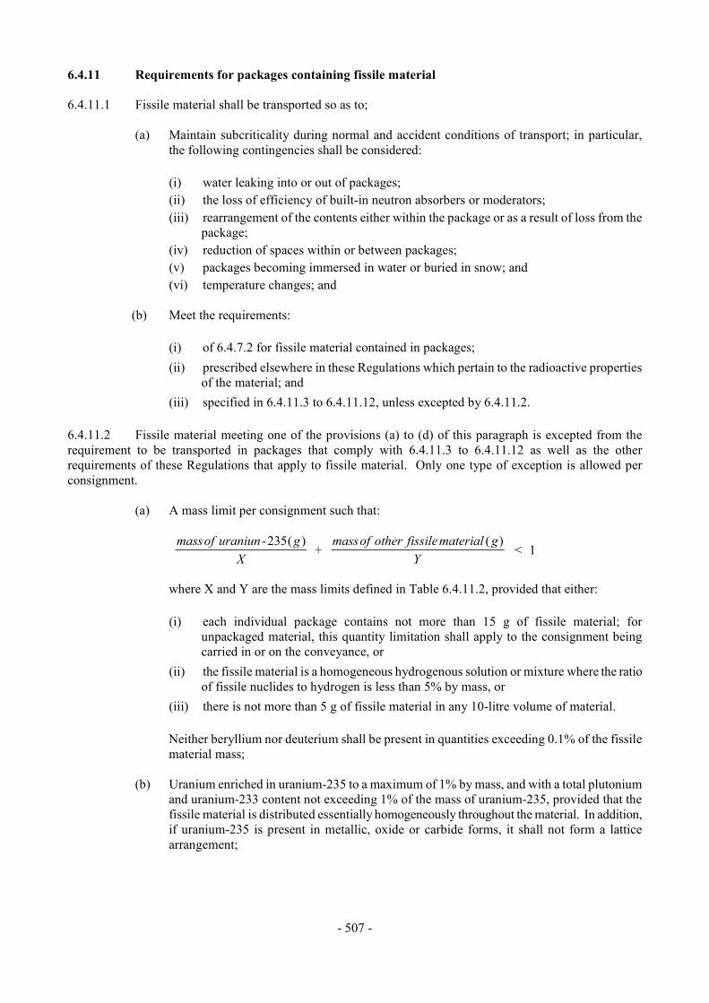
- 507 -
6.4.11 Requirements for packages containing fissile material
6.4.11.1 Fissile material shall be transported so as to;
(a) Maintain subcriticality during normal and accident conditions of transport; in particular, the following contingencies shall be considered:
(i) water leaking into or out of packages; (ii) the loss of efficiency of built-in neutron absorbers or moderators; (iii) rearrangement of the contents either within the package or as a result of loss from the
package; (iv) reduction of spaces within or between packages; (v) packages becoming immersed in water or buried in snow; and (vi) temperature changes; and
(b) Meet the requirements:
(i) of 6.4.7.2 for fissile material contained in packages; (ii) prescribed elsewhere in these Regulations which pertain to the radioactive properties
of the material; and (iii) specified in 6.4.11.3 to 6.4.11.12, unless excepted by 6.4.11.2.
6.4.11.2 Fissile material meeting one of the provisions (a) to (d) of this paragraph is excepted from the requirement to be transported in packages that comply with 6.4.11.3 to 6.4.11.12 as well as the other requirements of these Regulations that apply to fissile material. Only one type of exception is allowed per consignment.
(a) A mass limit per consignment such that:
massof uraniun gX
massof other fissile material gY
-+ <
2351
( ) ( )
where X and Y are the mass limits defined in Table 6.4.11.2, provided that either:
(i) each individual package contains not more than 15 g of fissile material; for
unpackaged material, this quantity limitation shall apply to the consignment being carried in or on the conveyance, or
(ii) the fissile material is a homogeneous hydrogenous solution or mixture where the ratio of fissile nuclides to hydrogen is less than 5% by mass, or
(iii) there is not more than 5 g of fissile material in any 10-litre volume of material.
Neither beryllium nor deuterium shall be present in quantities exceeding 0.1% of the fissile material mass;
(b) Uranium enriched in uranium-235 to a maximum of 1% by mass, and with a total plutonium
and uranium-233 content not exceeding 1% of the mass of uranium-235, provided that the fissile material is distributed essentially homogeneously throughout the material. In addition, if uranium-235 is present in metallic, oxide or carbide forms, it shall not form a lattice arrangement;
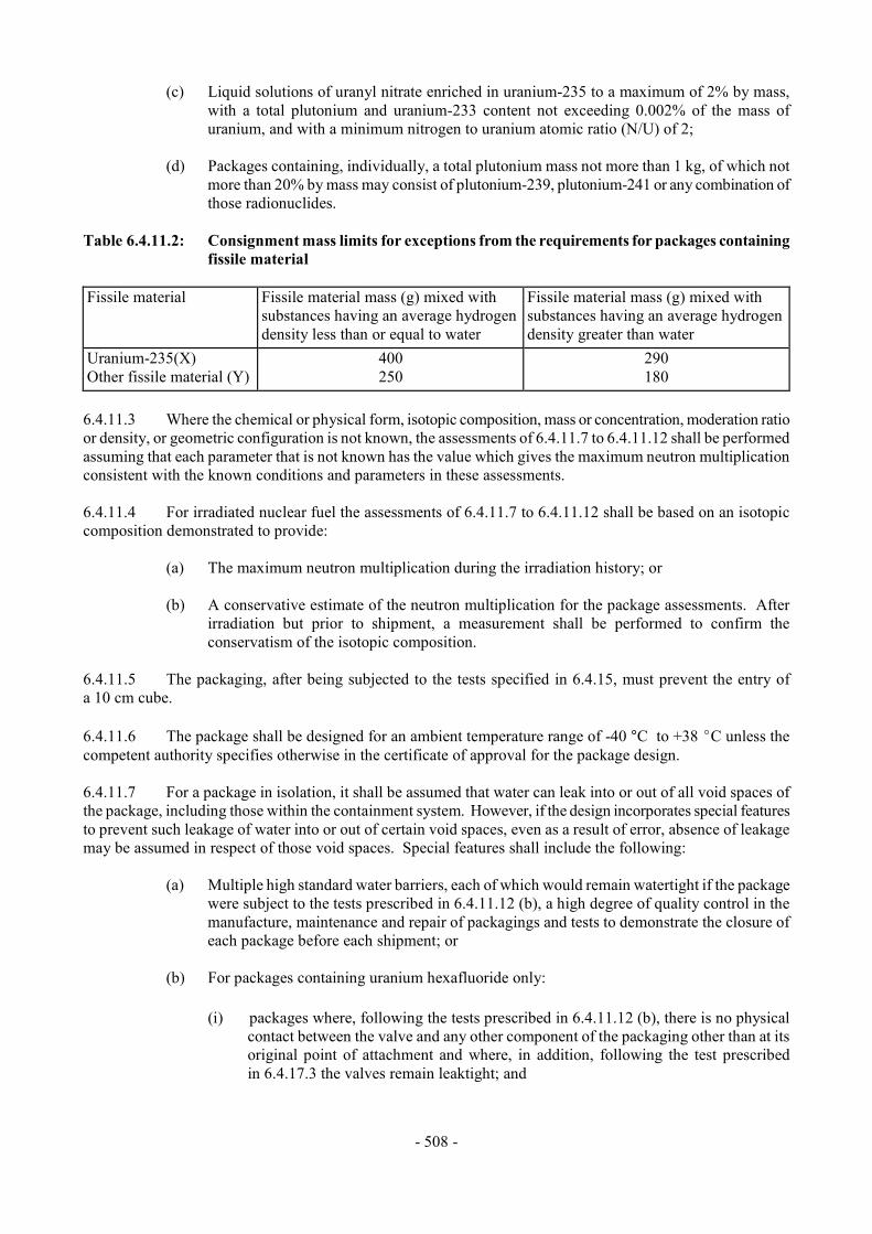
- 508 -
(c) Liquid solutions of uranyl nitrate enriched in uranium-235 to a maximum of 2% by mass, with a total plutonium and uranium-233 content not exceeding 0.002% of the mass of uranium, and with a minimum nitrogen to uranium atomic ratio (N/U) of 2;
(d) Packages containing, individually, a total plutonium mass not more than 1 kg, of which not
more than 20% by mass may consist of plutonium-239, plutonium-241 or any combination of those radionuclides.
Table 6.4.11.2: Consignment mass limits for exceptions from the requirements for packages containing
fissile material Fissile material Fissile material mass (g) mixed with
substances having an average hydrogen density less than or equal to water
Fissile material mass (g) mixed with substances having an average hydrogen density greater than water
Uranium-235(X) Other fissile material (Y)
400 250
290 180
6.4.11.3 Where the chemical or physical form, isotopic composition, mass or concentration, moderation ratio or density, or geometric configuration is not known, the assessments of 6.4.11.7 to 6.4.11.12 shall be performed assuming that each parameter that is not known has the value which gives the maximum neutron multiplication consistent with the known conditions and parameters in these assessments. 6.4.11.4 For irradiated nuclear fuel the assessments of 6.4.11.7 to 6.4.11.12 shall be based on an isotopic composition demonstrated to provide:
(a) The maximum neutron multiplication during the irradiation history; or
(b) A conservative estimate of the neutron multiplication for the package assessments. After irradiation but prior to shipment, a measurement shall be performed to confirm the conservatism of the isotopic composition.
6.4.11.5 The packaging, after being subjected to the tests specified in 6.4.15, must prevent the entry of a 10 cm cube. 6.4.11.6 The package shall be designed for an ambient temperature range of -40 °C to +38 EC unless the competent authority specifies otherwise in the certificate of approval for the package design. 6.4.11.7 For a package in isolation, it shall be assumed that water can leak into or out of all void spaces of the package, including those within the containment system. However, if the design incorporates special features to prevent such leakage of water into or out of certain void spaces, even as a result of error, absence of leakage may be assumed in respect of those void spaces. Special features shall include the following:
(a) Multiple high standard water barriers, each of which would remain watertight if the package were subject to the tests prescribed in 6.4.11.12 (b), a high degree of quality control in the manufacture, maintenance and repair of packagings and tests to demonstrate the closure of each package before each shipment; or
(b) For packages containing uranium hexafluoride only:
(i) packages where, following the tests prescribed in 6.4.11.12 (b), there is no physical
contact between the valve and any other component of the packaging other than at its original point of attachment and where, in addition, following the test prescribed in 6.4.17.3 the valves remain leaktight; and
- 509 -
(ii) a high degree of quality control in the manufacture, maintenance and repair of packagings coupled with tests to demonstrate closure of each package before each shipment.
6.4.11.8 It shall be assumed that the confinement system shall be closely reflected by at least 20 cm of water or such greater reflection as may additionally be provided by the surrounding material of the packaging. However, when it can be demonstrated that the confinement system remains within the packaging following the tests prescribed in 6.4.11.12 (b), close reflection of the package by at least 20 cm of water may be assumed in 6.4.11.9 (c). 6.4.11.9 The package shall be subcritical under the conditions of 6.4.11.7 and 6.4.11.8 with the package conditions that result in the maximum neutron multiplication consistent with:
(a) Routine conditions of transport (incident free);
(b) The tests specified in 6.4.11.11 (b);
(c) The tests specified in 6.4.11.12 (b). 6.4.11.10 For packages to be transported by air:
(a) The package shall be subcritical under conditions consistent with the tests prescribed in 6.4.20.1 assuming reflection by at least 20 cm of water but no water inleakage; and
(b) Allowance shall not be made for special features of 6.4.11.7 unless, following the tests
specified in 6.4.20.1 and, subsequently, 6.4.19.3, leakage of water into or out of the void spaces is prevented.
6.4.11.11 A number "N" shall be derived, such that five times "N" shall be subcritical for the arrangement and package conditions that provide the maximum neutron multiplication consistent with the following:
(a) There shall not be anything between the packages, and the package arrangement shall be reflected on all sides by at least 20 cm of water; and
(b) The state of the packages shall be their assessed or demonstrated condition if they had been
subjected to the tests specified in 6.4.15. 6.4.11.12 A number "N" shall be derived, such that two times "N" shall be subcritical for the arrangement and package conditions that provide the maximum neutron multiplication consistent with the following:
(a) Hydrogenous moderation between packages, and the package arrangement reflected on all sides by at least 20 cm of water; and
(b) The tests specified in 6.4.15 followed by whichever of the following is the more limiting:
(i) the tests specified in 6.4.17.2 (b) and, either 6.4.17.2 (c) for packages having a mass
not greater than 500 kg and an overall density not greater than 1000 kg/m3 based on the external dimensions, or 6.4.17.2 (a) for all other packages; followed by the test specified in 6.4.17.3 and completed by the tests specified in 6.4.19.1 to 6.4.19.3; or
(ii) the test specified in 6.4.17.4; and
- 510 -
(c) Where any part of the fissile material escapes from the containment system following the tests specified in 6.4.11.12 (b), it shall be assumed that fissile material escapes from each package in the array and all of the fissile material shall be arranged in the configuration and moderation that results in the maximum neutron multiplication with close reflection by at least 20 cm of water.
6.4.12 Test procedures and demonstration of compliance 6.4.12.1 Demonstration of compliance with the performance standards required in 2.7.3.3, 2.7.3.4, 2.7.4.1, 2.7.4.2, 2.7.10.1, 2.7.10.2 and 6.4.2 to 6.4.11 must be accomplished by any of the methods listed below or by a combination thereof.
(a) Performance of tests with specimens representing LSA-III material, or special form radioactive material, or low dispersible radioactive material or with prototypes or samples of the packaging, where the contents of the specimen or the packaging for the tests shall simulate as closely as practicable the expected range of radioactive contents and the specimen or packaging to be tested shall be prepared as presented for transport;
(b) Reference to previous satisfactory demonstrations of a sufficiently similar nature;
(c) Performance of tests with models of appropriate scale incorporating those features which are
significant with respect to the item under investigation when engineering experience has shown results of such tests to be suitable for design purposes. When a scale model is used, the need for adjusting certain test parameters, such as penetrator diameter or compressive load, shall be taken into account;
(d) Calculation, or reasoned argument, when the calculation procedures and parameters are
generally agreed to be reliable or conservative. 6.4.12.2 After the specimen, prototype or sample has been subjected to the tests, appropriate methods of assessment shall be used to assure that the requirements for the test procedures have been fulfilled in compliance with the performance and acceptance standards prescribed in 2.7.3.3, 2.7.3.4, 2.7.4.1, 2.7.4.2, 2.7.10.1, 2.7.10.2 and 6.4.2 to 6.4.11. 6.4.12.3 All specimens shall be inspected before testing in order to identify and record faults or damage including the following:
(a) Divergence from the design; (b) Defects in manufacture;
(c) Corrosion or other deterioration; and
(d) Distortion of features.
The containment system of the package shall be clearly specified. The external features of the specimen shall be clearly identified so that reference may be made simply and clearly to any part of such specimen.
- 511 -
6.4.13 Testing the integrity of the containment system and shielding and evaluating criticality safety After each of the applicable tests specified in 6.4.15 to 6.4.21:
(a) Faults and damage shall be identified and recorded;
(b) It shall be determined whether the integrity of the containment system and shielding has been retained to the extent required in 6.4.2 to 6.4.11 for the package under test; and
(c) For packages containing fissile material, it shall be determined whether the assumptions and
conditions used in the assessments required by 6.4.11.1 to 6.4.11.12 for one or more packages are valid.
6.4.14 Target for drop tests The target for the drop tests specified in 2.7.4.5 (a), 6.4.15.4, 6.4.16 (a), 6.4.17.2, 6.4.20.2, and 6.4.20.4 shall be a flat, horizontal surface of such a character that any increase in its resistance to displacement or deformation upon impact by the specimen would not significantly increase the damage to the specimen. 6.4.15 Test for demonstrating ability to withstand normal conditions of transport 6.4.15.1 The tests are: the water spray test, the free drop test, the stacking test and the penetration test. Specimens of the package shall be subjected to the free drop test, the stacking test and the penetration test, preceded in each case by the water spray test. One specimen may be used for all the tests, provided that the requirements of 6.4.15.2 are fulfilled. 6.4.15.2 The time interval between the conclusion of the water spray test and the succeeding test shall be such that the water has soaked in to the maximum extent, without appreciable drying of the exterior of the specimen. In the absence of any evidence to the contrary, this interval shall be taken to be two hours if the water spray is applied from four directions simultaneously. No time interval shall elapse, however, if the water spray is applied from each of the four directions consecutively. 6.4.15.3 Water spray test: The specimen shall be subjected to a water spray test that simulates exposure to rainfall of approximately 5 cm per hour for at least one hour. 6.4.15.4 Free drop test: The specimen shall drop onto the target so as to suffer maximum damage in respect of the safety features to be tested.
(a) The height of drop measured from the lowest point of the specimen to the upper surface of the target shall be not less than the distance specified in Table 6.4.15.4 for the applicable mass. The target shall be as defined in 6.4.14;
(b) For rectangular fibreboard or wood packages not exceeding a mass of 50 kg, a separate
specimen shall be subjected to a free drop onto each corner from a height of 0.3 m; (c) For cylindrical fibreboard packages not exceeding a mass of 100 kg, a separate specimen
shall be subjected to a free drop onto each of the quarters of each rim from a height of 0.3 m.
- 512 -
Table 6.4.15.4: Free drop distance for testing packages to normal conditions of transport
Package Mass (kg) Free drop distance (m) Package mass < 5000 5000 # Package mass < 10000 10000 # Package mass < 15000 15000 # Package mass
1.2 0.9 0.6 0.3
6.4.15.5 Stacking test: Unless the shape of the packaging effectively prevents stacking, the specimen shall be subjected, for a period of 24 h, to a compressive load equal to the greater of the following:
(a) The equivalent of 5 times the mass of the actual package; and
(b) The equivalent of 13 kPa multiplied by the vertically projected area of the package. The load shall be applied uniformly to two opposite sides of the specimen, one of which shall be the base on which the package would typically rest. 6.4.15.6 Penetration test: The specimen shall be placed on a rigid, flat, horizontal surface which will not move significantly while the test is being carried out.
(a) A bar of 3.2 cm in diameter with a hemispherical end and a mass of 6 kg shall be dropped and directed to fall, with its longitudinal axis vertical, onto the centre of the weakest part of the specimen, so that, if it penetrates sufficiently far, it will hit the containment system. The bar shall not be significantly deformed by the test performance;
(b) The height of drop of the bar measured from its lower end to the intended point of impact on
the upper surface of the specimen shall be 1 m. 6.4.16 Additional tests for Type A packages designed for liquids and gases A specimen or separate specimens shall be subjected to each of the following tests unless it can be demonstrated that one test is more severe for the specimen in question than the other, in which case one specimen shall be subjected to the more severe test.
(a) Free drop test: The specimen shall drop onto the target so as to suffer the maximum damage in respect of containment. The height of the drop measured from the lowest part of the specimen to the upper surface of the target shall be 9 m. The target shall be as defined in 6.4.14;
(b) Penetration test: The specimen shall be subjected to the test specified in 6.4.15.6 except that
the height of drop shall be increased to 1.7 m from the 1 m specified in 6.4.15.6 (b). 6.4.17 Tests for demonstrating ability to withstand accident conditions in transport 6.4.17.1 The specimen shall be subjected to the cumulative effects of the tests specified in 6.4.17.2 and 6.4.17.3, in that order. Following these tests, either this specimen or a separate specimen shall be subjected to the effect(s) of the water immersion test(s) as specified in 6.4.17.4 and, if applicable, 6.4.18.
- 513 -
6.4.17.2 Mechanical test: The mechanical test consists of three different drop tests. Each specimen shall be subjected to the applicable drops as specified in 6.4.8.7 or 6.4.11.12. The order in which the specimen is subjected to the drops shall be such that, on completion of the mechanical test, the specimen shall have suffered such damage as will lead to the maximum damage in the thermal test which follows.
(a) For drop I, the specimen shall drop onto the target so as to suffer the maximum damage, and the height of the drop measured from the lowest point of the specimen to the upper surface of the target shall be 9 m. The target shall be as defined in 6.4.14;
(b) For drop II, the specimen shall drop so as to suffer the maximum damage onto a bar rigidly
mounted perpendicularly on the target. The height of the drop measured from the intended point of impact of the specimen to the upper surface of the bar shall be 1 m. The bar shall be of solid mild steel of circular section, (15.0 " 0.5) cm in diameter and 20 cm long unless a longer bar would cause greater damage, in which case a bar of sufficient length to cause maximum damage shall be used. The upper end of the bar shall be flat and horizontal with its edges rounded off to a radius of not more than 6 mm. The target on which the bar is mounted shall be as described in 6.4.14;
(c) For drop III, the specimen shall be subjected to a dynamic crush test by positioning the
specimen on the target so as to suffer maximum damage by the drop of a 500 kg mass from 9 m onto the specimen. The mass shall consist of a solid mild steel plate 1 m by 1 m and shall fall in a horizontal attitude. The height of the drop shall be measured from the underside of the plate to the highest point of the specimen. The target on which the specimen rests shall be as defined in 6.4.14.
6.4.17.3 Thermal test: The specimen shall be in thermal equilibrium under conditions of an ambient temperature of 38 °C, subject to the solar insolation conditions specified in Table 6.4.8.5 and subject to the design maximum rate of internal heat generation within the package from the radioactive contents. Alternatively, any of these parameters are allowed to have different values prior to and during the test, providing due account is taken of them in the subsequent assessment of package response. The thermal test shall then consist of:
(a) Exposure of a specimen for a period of 30 minutes to a thermal environment which provides a heat flux at least equivalent to that of a hydrocarbon fuel/air fire in sufficiently quiescent ambient conditions to give a minimum average flame emissivity coefficient of 0.9 and an average temperature of at least 800 °C, fully engulfing the specimen, with a surface absorbtivity coefficient of 0.8 or that value which the package may be demonstrated to possess if exposed to the fire specified, followed by;
(b) Exposure of the specimen to an ambient temperature of 38 °C, subject to the solar insolation
conditions specified in Table 6.4.8.5 and subject to the design maximum rate of internal heat generation within the package by the radioactive contents for a sufficient period to ensure that temperatures in the specimen are everywhere decreasing and/or are approaching initial steady state conditions. Alternatively, any of these parameters are allowed to have different values following cessation of heating, providing due account is taken of them in the subsequent assessment of package response.
During and following the test the specimen shall not be artificially cooled and any combustion of materials of the specimen shall be permitted to proceed naturally. 6.4.17.4 Water immersion test: The specimen shall be immersed under a head of water of at least 15 m for a period of not less than eight hours in the attitude which will lead to maximum damage. For demonstration purposes, an external gauge pressure of at least 150 kPa shall be considered to meet these conditions.

- 514 -
6.4.18 Enhanced water immersion test for type B(U) and type B(M) packages containing more than 105 A2 and type C packages Enhanced water immersion test: The specimen shall be immersed under a head of water of at least 200 m for a period of not less than one hour. For demonstration purposes, an external gauge pressure of at least 2 MPa shall be considered to meet these conditions. 6.4.19 Water leakage test for package containing fissile material 6.4.19.1 Packages for which water in-leakage or out-leakage to the extent which results in greatest reactivity has been assumed for purposes of assessment under 6.4.11.7 to 6.4.11.12 shall be excepted from the test. 6.4.19.2 Before the specimen is subjected to the water leakage test specified below, it shall be subjected to the tests in 6.4.17.2 (b), and either 6.4.17.2 (a) or (c) as required by 6.4.11.12, and the test specified in 6.4.17.3. 6.4.19.3 The specimen shall be immersed under a head of water of at least 0.9 m for a period of not less than eight hours and in the attitude for which maximum leakage is expected. 6.4.20 Tests for Type C packages 6.4.20.1 Specimens shall be subjected to the effects of each of the following test sequences in the orders specified:
(a) The tests specified in 6.4.17.2 (a), 6.4.17.2 (c), 6.4.20.2 and 6.4.20.3; and
(b) The test specified in 6.4.20.4. Separate specimens are allowed to be used for each of the sequences (a) and (b). 6.4.20.2 Puncture/tearing test: The specimen shall be subjected to the damaging effects of a solid probe made of mild steel. The orientation of the probe to the surface of the specimen shall be as to cause maximum damage at the conclusion of the test sequence specified in 6.4.20.1 (a).
(a) The specimen, representing a package having a mass less than 250 kg, shall be placed on a target and subjected to a probe having a mass of 250 kg falling from a height of 3 m above the intended impact point. For this test the probe shall be a 20 cm diameter cylindrical bar with the striking end forming a frustum of a right circular cone with the following dimensions: 30 cm height and 2.5 cm in diameter at the top. The target on which the specimen is placed shall be as specified in 6.4.14;
(b) For packages having a mass of 250 kg or more, the base of the probe shall be placed on a
target and the specimen dropped onto the probe. The height of the drop, measured from the point of impact with the specimen to the upper surface of the probe shall be 3 m. For this test the probe shall have the same properties and dimensions as specified in (a) above, except that the length and mass of the probe shall be such as to incur maximum damage to the specimen. The target on which the base of the probe is placed shall be as specified in 6.4.14.
6.4.20.3 Enhanced thermal test: The conditions for this test shall be as specified in 6.4.17.3, except that the exposure to the thermal environment shall be for a period of 60 minutes.
- 515 -
6.4.20.4 Impact test: The specimen shall be subject to an impact on a target at a velocity of not less than 90 m/s, at such an orientation as to suffer maximum damage. The target shall be as defined in 6.4.14. 6.4.21 Tests for packagings designed to contain uranium hexafluoride Specimens that comprise or simulate packagings designed to contain 0.1 kg or more of uranium hexafluoride shall be tested hydraulically at an internal pressure of at least 1.4 MPa but, when the test pressure is less than 2.8 MPa, the design shall require multilateral approval. For retesting packagings, any other equivalent non-destructive testing may be applied subject to multilateral approval. 6.4.22 Approvals of package designs and materials 6.4.22.1 The approval of designs for packages containing 0.1 kg or more of uranium hexafluoride requires that:
(a) After 31 December 2000, each design that meets the requirements of 6.4.6.4 shall require multilateral approval;
(b) After 31 December 2003, each design that meets the requirements of 6.4.6.1 to 6.4.6.3 shall
require unilateral approval by the competent authority of the country of origin of the design; 6.4.22.2 Each Type B(U) and Type C package design shall require unilateral approval, except that:
(a) A package design for fissile material, which is also subject to 6.4.22.4, 6.4.23.7, and 5.1.5.3.1 shall require multilateral approval; and
(b) A Type B(U) package design for low dispersible radioactive material shall require
multilateral approval. 6.4.22.3 Each Type B(M) package design, including those for fissile material which are also subject to 6.4.22.4, 6.4.23.7, and 5.1.5.3.1 and those for low dispersible radioactive material, shall require multilateral approval. 6.4.22.4 Each package design for fissile material which is not excepted according to 6.4.11.2 from the requirements that apply specifically to packages containing fissile material shall require multilateral approval. 6.4.22.5 The design for special form radioactive material shall require unilateral approval. The design for low dispersible radioactive material shall require multilateral approval (see also 6.4.23.8). 6.4.23 Applications and approvals for radioactive material transport 6.4.23.1 [reserved] 6.4.23.2 An application for shipment approval shall include:
(a) The period of time, related to the shipment, for which the approval is sought;
(b) The actual radioactive contents, the expected modes of transport, the type of conveyance, and the probable or proposed route; and
- 516 -
(c) The details of how the precautions and administrative or operational controls, referred to in the package design approval certificates issued under 5.1.5.3.1, are to be put into effect.
6.4.23.3 An application for approval of shipments under special arrangement shall include all the information necessary to satisfy the competent authority that the overall level of safety in transport is at least equivalent to that which would be provided if all the applicable requirements of these Regulations had been met. The application shall also include:
(a) A statement of the respects in which, and of the reasons why, the consignment cannot be made in full accordance with the applicable requirements; and
(b) A statement of any special precautions or special administrative or operational controls
which are to be employed during transport to compensate for the failure to meet the applicable requirements.
6.4.23.4 An application for approval of Type B(u) or Type C package design shall include:
(a) A detailed description of the proposed radioactive contents with reference to their physical and chemical states and the nature of the radiation emitted;
(b) A detailed statement of the design, including complete engineering drawings and schedules
of materials and methods of manufacture;
(c) A statement of the tests which have been done and their results, or evidence based on calculative methods or other evidence that the design is adequate to meet the applicable requirements;
(d) The proposed operating and maintenance instructions for the use of the packaging;
(e) If the package is designed to have a maximum normal operating pressure in excess of
100 kPa gauge, a specification of the materials of manufacture of the containment system, the samples to be taken, and the tests to be made;
(f) Where the proposed radioactive contents are irradiated fuel, a statement and a justification of
any assumption in the safety analysis relating to the characteristics of the fuel and a description of any pre-shipment measurement as required by 6.4.11.4 (b);
(g) Any special stowage provisions necessary to ensure the safe dissipation of heat from the
package considering the various modes of transport to be used and type of conveyance or freight container;
(h) A reproducible illustration, not larger than 21 cm by 30 cm, showing the make-up of the
package; and
(i) A specification of the applicable quality assurance programme as required by 1.1.2.3.1. 6.4.23.5 An application for approval of a Type B(M) package design shall include, in addition to the general information required for package approval in 6.4.23.4 for Type B(U) packages:
(a) A list of the requirements specified in 6.4.7.5, 6.4.8.4, 6.4.8.5 and 6.4.8.8-6.4.8.15 with which the package does not conform;
- 517 -
(b) Any proposed supplementary operational controls to be applied during transport not regularly provided for in these Regulations, but which are necessary to ensure the safety of the package or to compensate for the deficiencies listed in (a) above;
(c) A statement relative to any restrictions on the mode of transport and to any special loading,
carriage, unloading or handling procedures; and
(d) The range of ambient conditions (temperature, solar radiation) which are expected to be encountered during transport and which have been taken into account in the design.
6.4.23.6 The application for approval of designs for packages containing 0.1 kg or more of uranium hexafluoride shall include all information necessary to satisfy the competent authority that the design meets the applicable requirements 6.4.6.1, and a specification of the applicable quality assurance programme as required in 1.1.2.3.1. 6.4.23.7 An application for a fissile package approval shall include all information necessary to satisfy the competent authority that the design meets the applicable requirements of 6.4.11.1, and a specification of the applicable quality assurance programme as required by 1.1.2.3.1. 6.4.23.8 An application for approval of design for special form radioactive material and design for low dispersible radioactive material shall include:
(a) A detailed description of the radioactive material or, if a capsule, the contents; particular reference shall be made to both physical and chemical states;
(b) A detailed statement of the design of any capsule to be used; (c) A statement of the tests which have been done and their results, or evidence based on
calculative methods to show that the radioactive material is capable of meeting the performance standards, or other evidence that the special form radioactive material or low dispersible radioactive material meets the applicable requirements of these Regulations;
(d) A specification of the applicable quality assurance programme as required in 1.1.2.3.1; and (e) Any proposed pre-shipment actions for use in the consignment of special form radioactive
material or low dispersible radioactive material. 6.4.23.9 Each approval certificate issued by a competent authority shall be assigned an identification mark. The mark shall be of the following generalized type: VRI/Number/Type Code
(a) Except as provided in 6.4.23.10 (b), VRI represents the international vehicle registration identification code of the country issuing the certificate1;
(b) The number shall be assigned by the competent authority, and shall be unique and specific
with regard to the particular design or shipment. The shipment approval identification mark shall be clearly related to the design approval identification mark;
1 See Vienna Convention on Road Traffic (1968).

- 518 -
(c) The following type codes shall be used in the order listed to indicate the types of approval certificates issued:
AF Type A package design for fissile material B(U) Type B(U) package design (B(U)F if for fissile material) B(M) Type B(M) package design (B(M)F if for fissile material) C Type C package design (CF if for fissile material) IF Industrial package design for fissile material S Special form radioactive material LD Low dispersible radioactive material T Shipment X Special arrangement
In the case of package designs for non-fissile or fissile excepted uranium hexafluoride, where
none of the above codes apply, then the following type codes shall be used: H(U) Unilateral approval H(M) Multilateral approval; (d) For package design and special form radioactive material approval certificates, other than
those issued under transitional packaging the provisions of 6.24.2-6.24.4, and for low dispersible radioactive material approval certificates, the symbols "-96" shall be added to the type code.
6.4.23.10 These type codes shall be applied as follows: (a) Each certificate and each package shall bear the appropriate identification mark, comprising
the symbols prescribed in 6.4.23.9 (a), (b), (c) and (d) above, except that, for packages, only the applicable design type codes including, if applicable, the symbols "-96", shall appear following the second stroke, that is, the "T" or "X" shall not appear in the identification marking on the package. Where the design approval and shipment approval are combined, the applicable type codes do not need to be repeated. For example:
A/132/B(M)F-96: A Type B(M) package design approved for fissile material, requiring
multilateral approval, for which the competent authority of Austria has assigned the design number 132 (to be marked on both the package and on the package design approval certificate);
A/132/B(M)F-96T: The shipment approval issued for a package bearing the identification
mark elaborated above (to be marked on the certificate only);
A/137/X: A special arrangement approval issued by the competent authority of Austria, to which the number 137 has been assigned (to be marked on the certificate only);
A/139/IF-96: An Industrial package design for fissile material approved by the
competent authority of Austria, to which package design number 139 has been assigned (to be marked on both the package and on the package design approval certificate); and
A/145/H(U)-96: A package design for fissile excepted uranium hexafluoride approved
by the competent authority of Austria, to which package design number 145 has been assigned (to be marked on both the package and on the package design approval certificate);

- 519 -
(b) Where multilateral approval is effected by validation according to 6.4.23.16, only the identification mark issued by the country of origin of the design or shipment shall be used. Where multilateral approval is effected by issue of certificates by successive countries, each certificate shall bear the appropriate identification mark and the package whose design was so approved shall bear all appropriate identification marks.
For example:
A/132/B(M)F-96 CH/28/B(M)F-96
would be the identification mark of a package which was originally approved by Austria and was subsequently approved, by separate certificate, by Switzerland. Additional identification marks would be tabulated in a similar manner on the package;
(c) The revision of a certificate shall be indicated by a parenthetical expression following the
identification mark on the certificate. For example, A/132/B(M)F-96(Rev.2) would indicate revision 2 of the Austrian package design approval certificate; or A/132/B(M)F-96(Rev.0) would indicate the original issuance of the Austrian package design approval certificate. For original issuances, the parenthetical entry is optional and other words such as 'original issuance' may also be used in place of 'Rev.0'. Certificate revision numbers may only be issued by the country issuing the original approval certificate;
(d) Additional symbols (as may be necessitated by national requirements) may be added in
brackets to the end of the identification mark; for example, A/132/B(M)F to 96(SP503);
(e) It is not necessary to alter the identification mark on the packaging each time that a revision to the design certificate is made. Such re-marking shall be required only in those cases where the revision to the package design certificate involves a change in the letter type codes for the package design following the second stroke.
6.4.23.11 Each approval certificate issued by a competent authority for special form radioactive material or
low dispersible radioactive material shall include the following information:
(a) Type of certificate;
(b) The competent authority identification mark;
(c) The issue date and an expiry date;
(d) List of applicable national and international regulations, including the edition of the IAEA Regulations for the Safe Transport of Radioactive Material under which the special form radioactive material or low dispersible radioactive material is approved;
(e) The identification of the special form radioactive material or low dispersible radioactive
material;
(f) A description of the special form radioactive material or low dispersible radioactive material;
(g) Design specifications for the special form radioactive material or low dispersible radioactive material which may include references to drawings;

- 520 -
(h) A specification of the radioactive contents which includes the activities involved and which may include the physical and chemical form;
(i) A specification of the applicable quality assurance programme as required in 1.1.2.3.1;
(j) Reference to information provided by the applicant relating to specific actions to be taken
prior to shipment; (k) If deemed appropriate by the competent authority, reference to the identity of the applicant;
(l) Signature and identification of the certifying official.
6.4.23.12 Each approval certificate issued by a competent authority for a special arrangement shall include the following information:
(a) Type of certificate;
(b) The competent authority identification mark;
(c) The issue date and an expiry date;
(d) Mode(s) of transport; (e) Any restrictions on the modes of transport, type of conveyance, freight container, and any
necessary routing instructions;
(f) List of applicable national and international regulations, including the edition of the IAEA Regulations for the Safe Transport of Radioactive Material under which the special arrangement is approved;
(g) The following statement:
"This certificate does not relieve the consignor from compliance with any requirement of the government of any country through or into which the package will be transported.";
(h) References to certificates for alternative radioactive contents, other competent authority
validation, or additional technical data or information, as deemed appropriate by the competent authority;
(i) Description of the packaging by a reference to the drawings or a specification of the design.
If deemed appropriate by the competent authority, a reproducible illustration, not larger than 21 cm by 30 cm, showing the make-up of the package shall also be provided, accompanied by a brief description of the packaging, including materials of manufacture, gross mass, general outside dimensions and appearance;
(j) A specification of the authorized radioactive contents, including any restrictions on the
radioactive contents which might not be obvious from the nature of the packaging. This shall include the physical and chemical forms, the activities involved (including those of the various isotopes, if appropriate), amounts in grams (for fissile material), and whether special form radioactive material or low dispersible radioactive material, if applicable;

- 521 -
(k) Additionally, for packages containing fissile material:
(i) a detailed description of the authorized radioactive contents; (ii) the value of the criticality safety index; (iii) reference to the documentation that demonstrates the criticality safety of the contents; (iv) any special features, on the basis of which the absence of water from certain void
spaces has been assumed in the criticality assessment; (v) any allowance (based on 6.4.11.4 (b)) for a change in neutron multiplication assumed
in the criticality assessment as a result of actual irradiation experience; and (vi) the ambient temperature range for which the special arrangement has been approved;
(l) A detailed listing of any supplementary operational controls required for preparation,
loading, carriage, unloading and handling of the consignment, including any special stowage provisions for the safe dissipation of heat;
(m) If deemed appropriate by the competent authority, reasons for the special arrangement;
(n) Description of the compensatory measures to be applied as a result of the shipment being
under special arrangement;
(o) Reference to information provided by the applicant relating to the use of the packaging or specific actions to be taken prior to the shipment;
(p) A statement regarding the ambient conditions assumed for purposes of design if these are not
in accordance with those specified in 6.4.8.4, 6.4.8.5, and 6.4.8.15, as applicable;
(q) Any emergency arrangements deemed necessary by the competent authority;
(r) A specification of the applicable quality assurance programme as required in 1.1.2.3.1; (s) If deemed appropriate by the competent authority, reference to the identity of the applicant
and to the identity of the carrier;
(t) Signature and identification of the certifying official. 6.4.23.13 Each approval certificate for a shipment issued by a competent authority shall include the following information:
(a) Type of certificate;
(b) The competent authority identification mark(s);
(c) The issue date and an expiry date;
(d) List of applicable national and international regulations, including the edition of the IAEA Regulations for the Safe Transport of Radioactive Material under which the shipment is approved;
(e) Any restrictions on the modes of transport, type of conveyance, freight container, and any
necessary routeing instructions;
- 522 -
(f) The following statement:
"This certificate does not relieve the consignor from compliance with any requirement of the government of any country through or into which the package will be transported.";
(g) A detailed listing of any supplementary operational controls required for preparation,
loading, carriage, unloading and handling of the consignment, including any special stowage provisions for the safe dissipation of heat or maintenance of criticality safety;
(h) Reference to information provided by the applicant relating to specific actions to be taken
prior to the shipment;
(i) Reference to the applicable design approval certificate(s);
(j) A specification of the actual radioactive contents, including any restrictions on the radioactive contents which might not be obvious from the nature of the packaging. This shall include the physical and chemical forms, the total activities involved (including those of the various isotopes, if appropriate), amounts in grams (for fissile material), and whether special form radioactive material or low dispersible radioactive material, if applicable;
(k) Any emergency arrangements deemed necessary by the competent authority;
(l) A specification of the applicable quality assurance programme as required in 1.1.2.3.1;
(m) If deemed appropriate by the competent authority, reference to the identity of the applicant;
(n) Signature and identification of the certifying official.
6.4.23.14 Each approval certificate of the design of a package issued by a competent authority shall include the following information:
(a) Type of certificate;
(b) The competent authority identification mark; (c) The issue date and an expiry date; (d) Any restriction on the modes of transport, if appropriate; (e) List of applicable national and international regulations, including the edition of the IAEA
Regulations for the Safe Transport of Radioactive Material under which the design is approved;
(f) The following statement: "This certificate does not relieve the consignor from compliance with any requirement of the
government of any country through or into which the package will be transported."; (g) References to certificates for alternative radioactive contents, other competent authority
validation, or additional technical data or information, as deemed appropriate by the competent authority;

- 523 -
(h) A statement authorizing shipment where shipment approval is required under 5.1.5.2.2, if deemed appropriate;
(i) Identification of the packaging; (j) Description of the packaging by a reference to the drawings or specification of the design.
If deemed appropriate by the competent authority, a reproducible illustration, not larger than 21 cm by 30 cm, showing the make-up of the package should also be provided, accompanied by a brief description of the packaging, including materials of manufacture, gross mass, general outside dimensions and appearance;
(k) Specification of the design by reference to the drawings;
(l) A specification of the authorized radioactive content, including any restrictions on the
radioactive contents which might not be obvious from the nature of the packaging. This shall include the physical and chemical forms, the activities involved (including those of the various isotopes, if appropriate), amounts in grams (for fissile material), and whether special form radioactive material or low dispersible radioactive material, if applicable;
(m) Additionally, for packages containing fissile material:
(i) a detailed description of the authorized radioactive contents; (ii) the value of the criticality safety index; (iii) reference to the documentation that demonstrates the criticality safety of the contents; (iv) any special features, on the basis of which the absence of water from certain void
spaces has been assumed in the criticality assessment; (v) any allowance (based on 6.4.11.4 (b)) for a change in neutron multiplication assumed
in the criticality assessment as a result of actual irradiation experience; and (vi) the ambient temperature range for which the package design has been approved;
(n) For Type B(M) packages, a statement specifying those prescriptions of 6.4.7.5, 6.4.8.4,
6.4.8.5 and 6.4.8.8 to 6.4.8.15 with which the package does not conform and any amplifying information which may be useful to other competent authorities;
(o) A detailed listing of any supplementary operational controls required for preparation,
loading, carriage, unloading and handling of the consignment, including any special stowage provisions for the safe dissipation of heat;
(p) Reference to information provided by the applicant relating to the use of the packaging or
specific actions to be taken prior to shipment; (q) A statement regarding the ambient conditions assumed for purposes of design if these are not
in accordance with those specified in 6.4.8.4, 6.4.8.5 and 6.4.8.15, as applicable; (r) A specification of the applicable quality assurance programme as required in 1.1.2.3.1; (s) Any emergency arrangements deemed necessary by the competent authority; (t) If deemed appropriate by the competent authority, reference to the identity of the applicant; (u) Signature and identification of the certifying official.

- 524 -
6.4.23.15 The competent authority shall be informed of the serial number of each packaging manufactured to a design approved by them. The competent authority shall maintain a register of such serial numbers. 6.4.23.16 Multilateral approval may be by validation of the original certificate issued by the competent authority of the country of origin of the design or shipment. Such validation may take the form of an endorsement on the original certificate or the issuance of a separate endorsement, annex, supplement, etc., by the competent authority of the country through or into which the shipment is made. 6.4.24 Transitional measures for Class 7 Packages not requiring competent authority approval of design under the 1985 and 1985 (as amended 1990) editions of IAEA Safety Series No. 6 6.4.24.1 Excepted packages, Industrial packages Type IP-1, Type IP-2 and Type IP-3 and Type A packages that did not require approval of design by the competent authority and which meet the requirements of the 1985 or 1985 (As Amended 1990) Editions of IAEA Regulations for the Safe Transport of Radioactive Material (IAEA Safety Series No. 6) may continue to be used subject to the mandatory programme of quality assurance in accordance with the requirements of 1.1.2.3.1 and the activity limits and material restrictions of 2.7.7. Any packaging modified, unless to improve safety, or manufactured after 31 December 2003, shall meet the requirements of these Regulations in full. Packages prepared for transport not later than 31 December 2003 under the 1985 or 1985 (As amended 1990) Editions of IAEA Safety Series No. 6 may continue in transport. Packages prepared for transport after this date shall meet the requirements of these Regulations in full. Packages approved under the 1973, 1973 (as amended), 1985 and 1985 (as amended 1990) editions of IAEA Safety Series No. 6 6.4.24.2 Packagings manufactured to a package design approved by the competent authority under the provisions of the 1973 or 1973 (As Amended) Editions of IAEA Safety Series No. 6 may continue to be used, subject to: multilateral approval of package design, the mandatory programme of quality assurance in accordance with the applicable requirements of 1.1.2.3.1; the activity limits and material restrictions of 2.7.7; and, for a package containing fissile material and transported by air, the requirement of 6.4.11.10. No new manufacture of such packaging shall be permitted to commence. Changes in the design of the packaging or in the nature or quantity of the authorized radioactive contents which, as determined by the competent authority, would significantly affect safety shall require that the requirements of these Regulations be met in full. A serial number according to the provision of 5.2.1.5.5 shall be assigned to and marked on the outside of each packaging. 6.4.24.3 Packagings manufactured to a package design approved by the competent authority under the provisions of the 1985 or 1985 (As Amended 1990) Editions of IAEA Safety Series No. 6 may continue to be used until 31 December 2003, subject to: the mandatory programme of quality assurance in accordance with the requirements of 1.1.2.3.1; the activity limits and material restrictions of 2.7.7; and, for a package containing fissile material and transported by air, the requirement of 6.4.11.10. After this date use may continue subject, additionally, to multilateral approval of package design. Changes in the design of the packaging or in the nature or quantity of the authorized radioactive contents which, as determined by the competent authority, would significantly affect safety shall require that the requirements of these Regulations be met in full. All packagings for which manufacture begins after 31 December 2006 shall meet the requirements of these Regulations in full.
- 525 -
Special form radioactive material approved under the 1973, 1973 (As Amended), 1985 and 1985 (As Amended 1990) Editions of these Regulations editions of IAEA Safety Series No. 6 6.4.24.4 Special form radioactive material manufactured to a design which had received unilateral approval by the competent authority under the 1973, 1973 (As Amended), 1985 or 1985 (As Amended 1990) Editions of IAEA Safety Series No. 6 may continue to be used when in compliance with the mandatory programme of quality assurance in accordance with the applicable requirements of 1.1.2.3.1. All special form radioactive material manufactured after 31 December 2003 shall meet the requirements of these Regulations in full.


- 527 -
CHAPTER 6.5
REQUIREMENTS FOR THE CONSTRUCTION AND TESTING OF INTERMEDIATE BULK CONTAINERS
6.5.1 General requirements applicable to all types of IBCs 6.5.1.1 Scope 6.5.1.1.1 The requirements of this Chapter apply to IBCs intended for the transport of certain dangerous goods. The provisions set out general requirements for multimodal transport and do not establish special requirements that may be required for a particular mode. 6.5.1.1.2 Exceptionally, IBCs and their service equipment not conforming strictly to the requirements herein, but having acceptable alternatives, may be considered by the competent authority for approval. In addition, in order to take into account progress in science and technology, the use of alternative arrangements which offer at least equivalent safety in use in respect of compatibility with the properties of the substances carried and equivalent or superior resistance to impact, loading and fire, may be considered by the competent authority. 6.5.1.1.3 The construction, equipment, testing, marking and operation of IBCs shall be subject to acceptance by the competent authority of the country in which the IBCs are approved. 6.5.1.1.4 Manufacturers and subsequent distributors of IBCs shall provide information regarding procedures to be followed and a description of the types and dimensions of closures (including required gaskets) and any other components needed to ensure that IBCs as presented for transport are capable of passing the applicable performance tests of this Chapter. 6.5.1.2 Definitions Body (for all categories of IBCs other than composite IBCs) means the receptacle proper, including openings and their closures, but does not include service equipment; Handling device (for flexible IBCs) means any sling, loop, eye or frame attached to the body of the IBC or formed from a continuation of the IBC body material; Maximum permissible gross mass means the mass of the IBC and any service or structural equipment together with the maximum net mass; Plastics, when used in connection with inner receptacles for composite IBCs, is taken to include other polymeric materials such as rubber, etc.; Protected (for metal IBCs) means being provided with additional protection against impact, the protection taking the form of, for example, a multi-layer (sandwich) or double wall construction or a frame with a metal lattice-work casing; Service equipment means filling and discharge devices and, according to the category of IBC, pressure-relief or venting, safety, heating and heat-insulating devices and measuring instruments; Structural equipment (for all categories of IBCs other than flexible IBCs) means the reinforcing, fastening, handling, protective or stabilizing members of the body, including the base pallet for composite IBCs with plastics inner receptacle, fibreboard and wooden IBCs;

- 528 -
Woven plastics (for flexible IBCs) means a material made from stretched tapes or monofilaments of a suitable plastics material. 6.5.1.3 Categories of IBCs 6.5.1.3.1 Metal IBCs consist of a metal body together with appropriate service and structural equipment. 6.5.1.3.2 Flexible IBCs consist of a body constituted of film, woven fabric or any other flexible material or combinations thereof, and if necessary an inner coating or liner, together with any appropriate service equipment and handling devices. 6.5.1.3.3 Rigid plastics IBCs consist of a rigid plastics body, which may have structural equipment together with appropriate service equipment. 6.5.1.3.4 Composite IBCs consist of structural equipment in the form of a rigid outer casing enclosing a plastics inner receptacle together with any service or other structural equipment. They are so constructed that the inner receptacle and outer casing once assembled, form and are used as, an integrated single unit to be filled, stored, transported or emptied as such. 6.5.1.3.5 Fibreboard IBCs consist of a fibreboard body with or without separate top and bottom caps, if necessary an inner liner (but no inner packagings), appropriate service and structural equipment. 6.5.1.3.6 Wooden IBCs consist of a rigid or collapsible wooden body together with an inner liner (but no inner packagings) and appropriate service and structural equipment. 6.5.1.4 Designatory code system for IBCs 6.5.1.4.1 The code shall consist of two Arabic numerals as specified in (a); followed by a capital letter(s) specified in (b); followed, when specified in an individual section, by an Arabic numeral indicating the category of IBC.
For solids filled or discharged (a) Type
by gravity under pressure of more than 10 kPa (0.1 bar)
For liquids
Rigid Flexible
11 13
21 -
31 -
(b) A. Steel (all types and surface treatments)
B. Aluminium C. Natural wood D. Plywood F. Reconstituted wood G. Fibreboard H. Plastics material L. Textile M. Paper, multiwall N. Metal (other than steel or aluminium).
6.5.1.4.2 For composite IBCs, two capital letters in Latin characters shall be used in sequence in the second position of the code. The first shall indicate the material of the inner receptacle of the IBC and the second that of the outer packaging of the IBC.
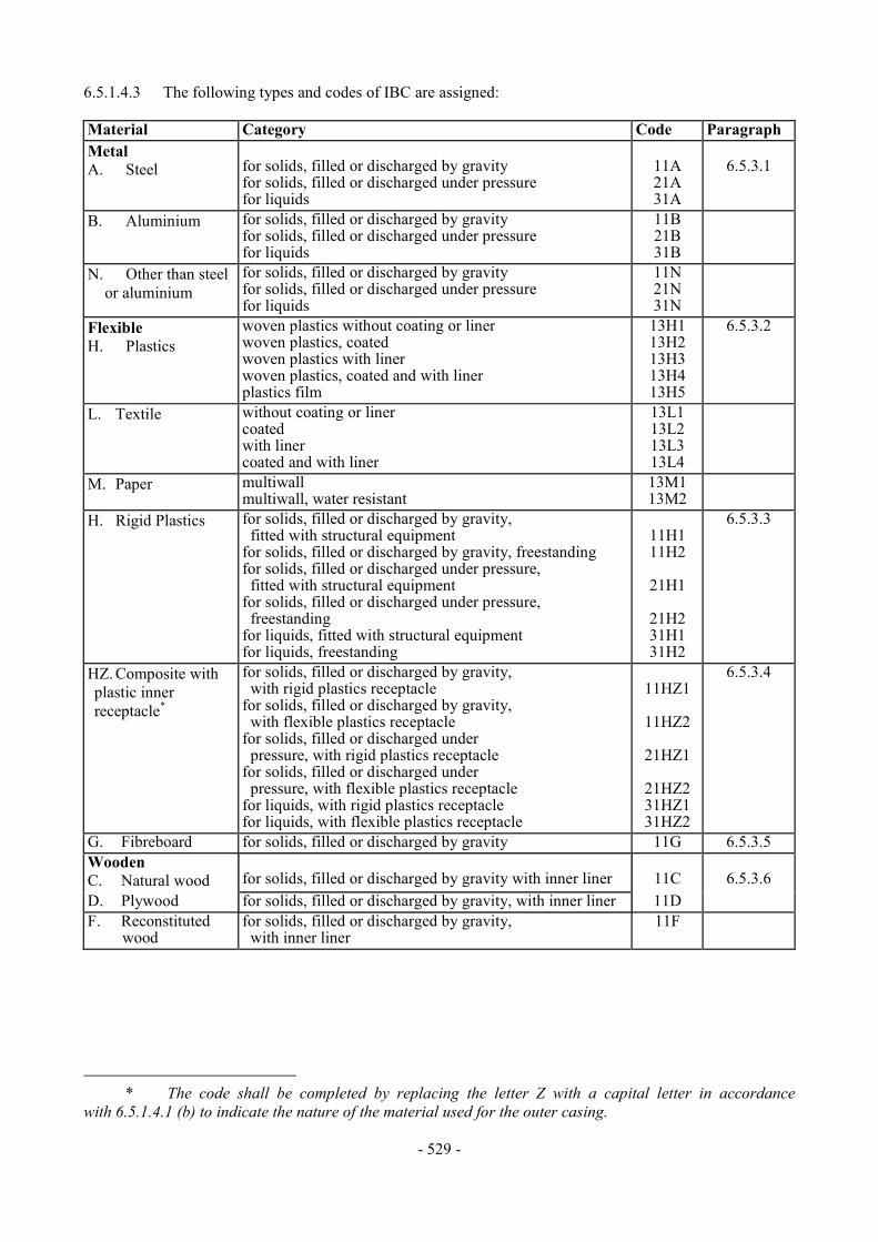
- 529 -
6.5.1.4.3 The following types and codes of IBC are assigned: Material Category Code Paragraph Metal A. Steel
for solids, filled or discharged by gravity for solids, filled or discharged under pressure for liquids
11A 21A 31A
6.5.3.1
B. Aluminium for solids, filled or discharged by gravity for solids, filled or discharged under pressure for liquids
11B 21B 31B
N. Other than steel or aluminium
for solids, filled or discharged by gravity for solids, filled or discharged under pressure for liquids
11N 21N 31N
Flexible H. Plastics
woven plastics without coating or liner woven plastics, coated woven plastics with liner woven plastics, coated and with liner plastics film
13H1 13H2 13H3 13H4 13H5
6.5.3.2
L. Textile without coating or liner coated with liner coated and with liner
13L1 13L2 13L3 13L4
M. Paper multiwall multiwall, water resistant
13M1 13M2
H. Rigid Plastics for solids, filled or discharged by gravity, fitted with structural equipment for solids, filled or discharged by gravity, freestanding for solids, filled or discharged under pressure, fitted with structural equipment for solids, filled or discharged under pressure, freestanding for liquids, fitted with structural equipment for liquids, freestanding
11H1 11H2
21H1
21H2 31H1 31H2
6.5.3.3
HZ. Composite with plastic inner receptacle*
for solids, filled or discharged by gravity, with rigid plastics receptacle for solids, filled or discharged by gravity, with flexible plastics receptacle for solids, filled or discharged under pressure, with rigid plastics receptacle for solids, filled or discharged under pressure, with flexible plastics receptacle for liquids, with rigid plastics receptacle for liquids, with flexible plastics receptacle
11HZ1
11HZ2
21HZ1
21HZ2 31HZ1 31HZ2
6.5.3.4
G. Fibreboard for solids, filled or discharged by gravity 11G 6.5.3.5 Wooden C. Natural wood
for solids, filled or discharged by gravity with inner liner
11C
6.5.3.6
D. Plywood for solids, filled or discharged by gravity, with inner liner 11D F. Reconstituted
wood for solids, filled or discharged by gravity, with inner liner
11F
* The code shall be completed by replacing the letter Z with a capital letter in accordance with 6.5.1.4.1 (b) to indicate the nature of the material used for the outer casing.

- 530 -
6.5.1.4.4 The letter "W" may follow the IBC code. The letter "W" signifies that the IBC, although of the same type indicated by the code, is manufactured to a specification different from those in section 6.5.3 and is considered equivalent in accordance with the requirements in 6.5.1.1.2. 6.5.1.5 Construction requirements 6.5.1.5.1 IBCs shall be resistant to or adequately protected from deterioration due to the external environment. 6.5.1.5.2 IBCs shall be so constructed and closed that none of the contents can escape under normal conditions of transport including the effect of vibration, or by changes in temperature, humidity or pressure. 6.5.1.5.3 IBCs and their closures shall be constructed of materials compatible with their contents, or be protected internally, so that they are not liable:
(a) To be attacked by the contents so as to make their use dangerous;
(b) To cause the contents to react or decompose, or form harmful or dangerous compounds with the IBCs.
6.5.1.5.4 Gaskets, where used, shall be made of materials not subject to attack by the contents of the IBCs. 6.5.1.5.5 All service equipment shall be so positioned or protected as to minimize the risk of escape of the contents owing to damage during handling and transport. 6.5.1.5.6 IBCs, their attachments and their service and structural equipment shall be designed to withstand, without loss of contents, the internal pressure of the contents and the stresses of normal handling and transport. IBCs intended for stacking shall be designed for stacking. Any lifting or securing features of IBCs shall be of sufficient strength to withstand the normal conditions of handling and transport without gross distortion or failure and shall be so positioned that no undue stress is caused in any part of the IBC. 6.5.1.5.7 Where an IBC consists of a body within a framework it shall be so constructed that:
(a) The body does not chafe or rub against the framework so as to cause material damage to the body;
(b) The body is retained within the framework at all times;
(c) The items of equipment are fixed in such a way that they cannot be damaged if the
connections between body and frame allow relative expansion or movement. 6.5.1.5.8 Where a bottom discharge valve is fitted, it shall be capable of being made secure in the closed position and the whole discharge system shall be suitably protected from damage. Valves having lever closures shall be able to be secured against accidental opening and the open or closed position shall be readily apparent. For IBCs containing liquids, a secondary means of sealing the discharge aperture shall also be provided, e.g. by a blank flange or equivalent device. 6.5.1.5.9 Each IBC shall be capable of passing the relevant performance tests.
- 531 -
6.5.1.6 Testing, certification and inspection
6.5.1.6.1 Quality assurance: the IBCs shall be manufactured and tested under a quality assurance programme which satisfies the competent authority, in order to ensure that each manufactured IBC meets the requirements of this Chapter. 6.5.1.6.2 Test requirements: IBCs shall be subject to design type tests and, if applicable, to initial and periodic tests in accordance with 6.5.4.14. 6.5.1.6.3 Certification: in respect of each design type of IBC a certificate and mark (as in 6.5.2) shall be issued attesting that the design type including its equipment meets the test requirements. 6.5.1.6.4 Inspection: every metal, rigid plastics and composite IBCs shall be inspected to the satisfaction of the competent authority:
(a) Before it is put into service, and thereafter at intervals not exceeding five years, with regard to:
(i) conformity to design type including marking; (ii) internal and external condition; (iii) proper functioning of service equipment;
Thermal insulation, if any, need be removed only to the extent necessary for a proper examination of the body of the IBC;
(b) At intervals of not more than two and a half years, with regard to:
(i) external condition; (ii) proper functioning of service equipment;
Thermal insulation, if any, need be removed only to the extent necessary for a proper examination of the body of the IBC.
A report of each inspection shall be kept by the owner of the IBC at least until the next inspection. The report shall include the results of the inspection and shall identify the party performing the inspection (see also the marking requirements in 6.5.2.2.1). 6.5.1.6.5 When an IBC is impaired as a result of impact (e.g. accident) or any other cause, it shall be repaired or otherwise maintained (see definition of "Routine maintenance of IBCs" in 1.2.1), so as to conform to the design type. The bodies of rigid plastics IBCs and the inner receptacles of composite IBCs that are impaired shall be replaced. 6.5.1.6.6 Repaired IBCs 6.5.1.6.6.1 In addition to any other testing and inspection requirements in these Regulations, an IBC shall be subjected to the full testing and inspection requirements set out in 6.5.4.14.3 and 6.5.1.6.4 (a), and the required reports shall be prepared, whenever it is repaired. 6.5.1.6.6.2 The Party performing the tests and inspections after the repair shall durably marking the IBC near the manufacturer's UN design type marking to show:
- 532 -
(a) the State in which the repair was carried out; (b) the name or authorized symbol of the party performing the repair; and (c) the date (month and year) of the tests and inspections. 6.5.1.6.6.3 Test and inspections performed in accordance with 6.5.1.6.6.1 may be considered to satisfy the requirements for the two and a half and five-year periodic tests and inspections. 6.5.1.6.7 The competent authority may at any time require proof, by tests in accordance with this Chapter, that IBCs meet the requirements of the design type tests. 6.5.2 Marking 6.5.2.1 Primary marking 6.5.2.1.1 Each IBC manufactured and intended for use according to these Regulations shall bear markings which are durable, legible and placed in a location so as to be readily visible. Letters, numerals and symbols shall be at least 12 mm high and shall show:
(a) The United Nations packaging symbol: For metal IBCs on which the marking is stamped or embossed, the capital letters 'UN'
may be applied instead of the symbol; (b) The code designating the type of IBC according to 6.5.1.4; (c) A capital letter designating the packing group(s) for which the design type has been
approved: (i) X for Packing groups I, II and III (IBCs for solids only); (ii) Y for Packing groups II and III;
(iii) Z for Packing group III only;
(d) The month and year (last two digits) of manufacture;
(e) The State authorizing the allocation of the mark; indicated by the distinguishing sign for motor vehicles in international traffic;
(f) The name or symbol of the manufacturer and other identification of the IBC as specified by
the competent authority;
(g) The stacking test load in kg. For IBCs not designed for stacking, the figure "0" shall be shown;
(h) The maximum permissible gross mass in kg.
Marking shall be applied in the sequence shown in (a) to (h); each element of the marking required
in these subparagraphs and when appropriate, 6.5.2.2, shall be clearly separated, e.g. by a slash or space and presented in a way that ensures that all of the parts of the mark may be easily identified.

- 533 -
Examples of markings for various types of IBC in accordance with (a) to (h) above:
11A/Y/02 89 NL/Mulder 007 5500/1500
For a metal IBC for solids discharged for instance by gravity and made from steel/for Packing Groups II and III/ manufactured in February 1989/authorized by the Netherlands/manufactured by Mulder and of a design type to which the competent authority has allocated serial number 007/the stacking test load in kg/the maximum permissible gross mass in kg.
13H3/Z/03 89 F/Meunier 17130/1500
For a flexible IBC for solids discharged for instance by gravity and made from woven plastics with a liner/not designed to be stacked.
31H1/Y/04 89 GB/9099 10800/1200
For a rigid plastics IBC for liquids made from plastics with structural equipment withstanding the stack load.
31HA1/Y/05 19 D/Muller 1683 10800/1200
For a composite IBC for liquids with a rigid plastics inner receptacle and a steel outer casing.
11C/X/01 93 S/Aurigny 9876 3000/910
For a wooden IBC for solids with an inner liner and authorized for Packing Group I solids.
6.5.2.2 Additional marking 6.5.2.2.1 Each IBC shall bear the markings required in 6.5.2.1 and, in addition, the following information which may appear on a corrosion-resistant plate permanently attached in a place readily accessible for inspection:
Category of IBC Additional marking Metal Rigid Plastics Composite Fibreboard Wooden
Capacity in litres* at 20 °C X X X Tare mass in kg* X X X X X Test (gauge) pressure, in kPa or bar*, if applicable
X X
Maximum filling/discharge pressure in kPa or bar*, if applicable
X X X
Body material and its minimum thickness in mm
X
Date of last leakproofness test, if applicable (month and year)
X X X
Date of last inspection (month and year) X X X Serial number of the manufacturer X
* The unit used shall be indicated.

- 534 -
6.5.2.2.2 In addition to the markings required in 6.5.2.1, flexible IBCs may bear a pictogram indicating recommended lifting methods. 6.5.2.2.3 The inner receptacle of composite IBCs shall be marked with at least the following information:
(a) The name or symbol of the manufacturer and other identification of the IBC as specified by the competent authority as in 6.5.2.1.1 (f);
(b) The date of manufacture, as in 6.5.2.1.1 (d);
(c) The distinguishing sign of the State authorizing the allocation of the mark, as in 6.5.2.1.1 (e). 6.5.2.2.4 Where a composite IBC is designed in such a manner that the outer casing is intended to be dismantled for transport when empty (such as for return of the IBC for reuse to the original consignor), each of the parts intended to be detached when so dismantled shall be marked with the month and year of manufacture and the name or symbol of the manufacturer and other identification of the IBC as specified by the competent authority (6.5.2.1.1(f)). 6.5.2.3 Conformity to design type. The marking indicates that IBCs correspond to a successfully tested design type and that the requirements referred to in the certificate have been met. 6.5.3 Specific requirements for IBCs 6.5.3.1 Specific requirements for metal IBCs 6.5.3.1.1 These requirements apply to metal IBCs intended for the transport of solids and liquids. There are three categories of metal IBCs:
(a) Those for solids which are filled or discharged by gravity (11A, 11B, 11N);
(b) Those for solids which are filled or discharged at a gauge pressure greater than 10 kPa
(0.1 bar) (21A, 21B, 21N); and
(c) Those for liquids (31A, 31B, 31N). 6.5.3.1.2 Bodies shall be made of suitable ductile metal in which the weldability has been fully demonstrated. Welds shall be skilfully made and afford complete safety. Low-temperature performance shall be taken into account when appropriate. 6.5.3.1.3 Care shall be taken to avoid damage by galvanic action due to the juxtaposition of dissimilar metals. 6.5.3.1.4 Aluminium IBCs intended for the carriage of flammable liquids shall have no movable parts, such as covers, closures, etc., made of unprotected steel liable to rust, which might cause a dangerous reaction by coming into frictional or percussive contact with the aluminium.
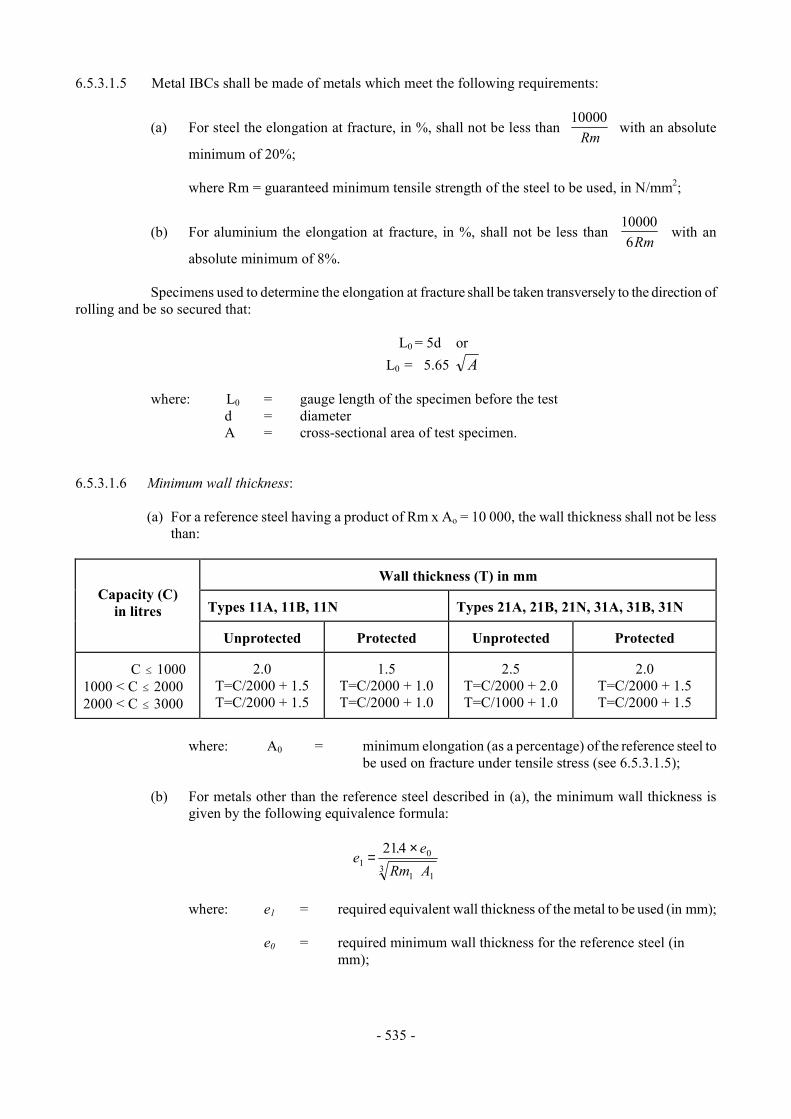
- 535 -
6.5.3.1.5 Metal IBCs shall be made of metals which meet the following requirements:
(a) For steel the elongation at fracture, in %, shall not be less than 10000
Rm with an absolute
minimum of 20%; where Rm = guaranteed minimum tensile strength of the steel to be used, in N/mm2;
(b) For aluminium the elongation at fracture, in %, shall not be less than 100006Rm
with an
absolute minimum of 8%. Specimens used to determine the elongation at fracture shall be taken transversely to the direction of rolling and be so secured that:
L0 = 5d or L0 = 5.65 A
where: L0 = gauge length of the specimen before the test
d = diameter A = cross-sectional area of test specimen.
6.5.3.1.6 Minimum wall thickness:
(a) For a reference steel having a product of Rm x Ao = 10 000, the wall thickness shall not be less than:
Wall thickness (T) in mm Types 11A, 11B, 11N
Types 21A, 21B, 21N, 31A, 31B, 31N
Capacity (C) in litres
Unprotected
Protected
Unprotected
Protected
C # 1000 1000 < C # 2000 2000 < C # 3000
2.0
T=C/2000 + 1.5 T=C/2000 + 1.5
1.5
T=C/2000 + 1.0 T=C/2000 + 1.0
2.5
T=C/2000 + 2.0 T=C/1000 + 1.0
2.0
T=C/2000 + 1.5 T=C/2000 + 1.5
where: A0 = minimum elongation (as a percentage) of the reference steel to
be used on fracture under tensile stress (see 6.5.3.1.5); (b) For metals other than the reference steel described in (a), the minimum wall thickness is
given by the following equivalence formula:
e eRm A1
0
1 13
214=
×.
where: e1 = required equivalent wall thickness of the metal to be used (in mm);
e0 = required minimum wall thickness for the reference steel (in mm);

- 536 -
Rm1 = guaranteed minimum tensile strength of the metal to be used (in N/mm2) (see (c));
A1 = minimum elongation (as a percentage) of the metal to be used on
fracture under tensile stress (see 6.5.3.1.5);
However, in no case shall the wall thickness be less than 1.5 mm.
(c) For purposes of the calculation described in (b), the guaranteed minimum tensile strength of the metal to be used (Rm1) shall be the minimum value according to national or international material standards. However, for austenitic steels, the specified minimum value for Rm according to the material standards may be increased by up to 15% when a greater value is attested in the material inspection certificate. When no material standard exists for the material in question, the value of Rm shall be the minimum value attested in the material inspection certificate.
6.5.3.1.7 Pressure relief requirements: IBCs for liquids shall be capable of releasing a sufficient amount of vapour in the event of fire engulfment to ensure that no rupture of the body will occur. This can be achieved by conventional pressure-relief devices or by other constructional means. The start-to-discharge pressure shall not be higher than 65 kPa (0.65 bar) and no lower than the total gauge pressure experienced in the IBC (i.e. the vapour pressure of the filling substance plus the partial pressure of the air or other inert gases, minus 100 kPa (1 bar)) at 55 °C, determined on the basis of a maximum degree of filling as defined in 4.1.1.4. The required relief devices shall be fitted in the vapour space. 6.5.3.2 Specific requirements for flexible IBCs 6.5.3.2.1 These requirements apply to flexible IBCs of the following types:
13H1 woven plastics without coating or liner 13H2 woven plastics, coated 13H3 woven plastics with liner 13H4 woven plastics, coated and with liner 13H5 plastics film 13L1 textile without coating or liner 13L2 textile, coated 13L3 textile with liner 13L4 textile, coated and with liner 13M1 paper, multiwall 13M2 paper, multiwall, water resistant
Flexible IBCs are intended for the transport of solids only.
6.5.3.2.2 Bodies shall be manufactured from suitable materials. The strength of the material and the construction of the flexible IBC shall be appropriate to its capacity and its intended use. 6.5.3.2.3 All materials used in the construction of flexible IBCs of types 13M1 and 13M2 shall, after complete immersion in water for not less than 24 hours, retain at least 85% of the tensile strength as measured originally on the material conditioned to equilibrium at 67% relative humidity or less. 6.5.3.2.4 Seams shall be formed by stitching, heat sealing, gluing or any equivalent method. All stitched seam-ends shall be secured. 6.5.3.2.5 Flexible IBCs shall provide adequate resistance to ageing and to degradation caused by ultraviolet radiation or the climatic conditions, or by the substance contained, thereby rendering them appropriate to their intended use.
- 537 -
6.5.3.2.6 For flexible plastics IBCs where protection against ultraviolet radiation is required, it shall be provided by the addition of carbon black or other suitable pigments or inhibitors. These additives shall be compatible with the contents and remain effective throughout the life of the body. Where use is made of carbon black, pigments or inhibitors other than those used in the manufacture of the tested design type, re-testing may be waived if changes in the carbon black content, the pigment content or the inhibitor content do not adversely affect the physical properties of the material of construction. 6.5.3.2.7 Additives may be incorporated into the material of the body to improve the resistance to ageing or to serve other purposes, provided that these do not adversely affect the physical or chemical properties of the material. 6.5.3.2.8 No material recovered from used receptacles shall be used in the manufacture of IBC bodies. Production residues or scrap from the same manufacturing process may, however, be used. Component parts such as fittings and pallet bases may also be used provided such components have not in any way been damaged in previous use. 6.5.3.2.9 When filled, the ratio of height to width shall be not more than 2:1. 6.5.3.2.10 The liner shall be made of a suitable material. The strength of the material used and the construction of the liner shall be appropriate to the capacity of the IBC and the intended use. Joins and closures shall be sift proof and capable of withstanding pressures and impacts liable to occur under normal conditions of handling and transport. 6.5.3.3 Specific requirements for rigid plastics IBCs 6.5.3.3.1 These requirements apply to rigid plastics IBCs for the transport of solids or liquids. Rigid plastics IBCs are of the following types:
11H1 fitted with structural equipment designed to withstand the whole load when IBCs are stacked, for solids which are filled or discharged by gravity
11H2 freestanding, for solids which are filled or discharged by gravity 21H1 fitted with structural equipment designed to withstand the whole load when IBCs are
stacked, for solids which are filled or discharged under pressure 21H2 freestanding, for solids which are filled or discharged under pressure 31H1 fitted with structural equipment designed to withstand the whole load when IBCs are
stacked, for liquids 31H2 freestanding, for liquids.
6.5.3.3.2 The body shall be manufactured from suitable plastics material of known specifications and be of adequate strength in relation to its capacity and its intended use. The material shall be adequately resistant to ageing and to degradation caused by the substance contained or, where relevant, by ultraviolet radiation. Low temperature performance shall be taken into account when appropriate. Any permeation of the substance contained shall not constitute a danger under normal conditions of transport. 6.5.3.3.3 Where protection against ultraviolet radiation is required, it shall be provided by the addition of carbon black or other suitable pigments or inhibitors. These additives shall be compatible with the contents and remain effective throughout the life of the body. Where use is made of carbon black, pigments or inhibitors other than those used in the manufacture of the tested design type, re-testing may be waived if changes in the carbon black content, the pigment content or the inhibitor content do not adversely affect the physical properties of the material of construction. 6.5.3.3.4 Additives may be incorporated in the material of the body to improve the resistance to ageing or to serve other purposes, provided that these do not adversely affect the physical or chemical properties of the material.

- 538 -
6.5.3.3.5 No used material other than production residues or regrind from the same manufacturing process may be used in the manufacture of rigid plastics IBCs. 6.5.3.4 Specific requirements for composite IBCs with plastics inner receptacles 6.5.3.4.1 These requirements apply to composite IBCs for the transport of solids and liquids of the following types:
11HZ1 composite IBCs with a rigid plastics inner receptacle, for solids filled or discharged by gravity
11HZ2 composite IBCs with a flexible plastics inner receptacle, for solids filled or discharged by gravity
21HZ1 composite IBCs with a rigid plastics inner receptacle, for solids filled or discharged under pressure
21HZ2 composite IBCs with a flexible plastics inner receptacle, for solids filled or discharged under pressure
31HZ1 composite IBCs with a rigid plastics inner receptacle, for liquids 31HZ2 composite IBCs with a flexible plastics inner receptacle, for liquids.
This code shall be completed by replacing the letter Z by a capital letter in accordance with
6.5.1.4.1 (b) to indicate the nature of the material used for the outer casing. 6.5.3.4.2 The inner receptacle is not intended to perform a containment function without its outer casing. A "rigid" inner receptacle is a receptacle which retains its general shape when empty without closures in place and without benefit of the outer casing. Any inner receptacle that is not "rigid" is considered to be "flexible". 6.5.3.4.3 The outer casing normally consists of rigid material formed so as to protect the inner receptacle from physical damage during handling and transport but is not intended to perform the containment function. It includes the base pallet where appropriate. 6.5.3.4.4 A composite IBC with a fully enclosing outer casing shall be so designed that the integrity of the inner container may be readily assessed following the leakproofness and hydraulic tests. 6.5.3.4.5 IBCs of type 31HZ2 shall be limited to a capacity of not more than 1250 litres. 6.5.3.4.6 The inner receptacle shall be manufactured from suitable plastics material of known specifications and be of adequate strength in relation to its capacity and its intended use. The material shall be adequately resistant to ageing and to degradation caused by the substance contained or, where relevant, by ultraviolet radiation. Low temperature performance shall be taken into account when appropriate. Any permeation of the substance contained shall not constitute a danger under normal conditions of transport. 6.5.3.4.7 Where protection against ultraviolet radiation is required, it shall be provided by the addition of carbon black or other suitable pigments or inhibitors. These additives shall be compatible with the contents and remain effective throughout the life of the inner receptacle. Where use is made of carbon black, pigments or inhibitors, other than those used in the manufacture of the tested design type, retesting may be waived if changes in carbon black content, the pigment content or the inhibitor content do not adversely affect the physical properties of the material of construction. 6.5.3.4.8 Additives may be incorporated in the material of the inner receptacle to improve the resistance to ageing or to serve other purposes, provided that these do not adversely affect the physical or chemical properties of the material. 6.5.3.4.9 No used material other than production residues or regrind from the same manufacturing process may be used in the manufacture of inner receptacles.

- 539 -
6.5.3.4.10 The inner receptacle of IBCs type 31HZ2 shall consist of at least three plies of film. 6.5.3.4.11 The strength of the material and the construction of the outer casing shall be appropriate to the capacity of the composite IBC and its intended use. 6.5.3.4.12 The outer casing shall be free of any projection that might damage the inner receptacle. 6.5.3.4.13 Outer casings of steel or aluminium shall be constructed of a suitable metal of adequate thickness. 6.5.3.4.14 Outer casings of natural wood shall be of well-seasoned wood, commercially dry and free from defects that would materially lessen the strength of any part of the casing. The tops and bottoms may be made of water resistant reconstituted wood such as hardboard, particle board or other suitable type. 6.5.3.4.15 Outer casings of plywood shall be made of well-seasoned rotary cut, sliced or sawn veneer, commercially dry and free from defects that would materially lessen the strength of the casing. All adjacent plies shall be glued with water resistant adhesive. Other suitable materials may be used with plywood for the construction of casings. Casings shall be firmly nailed or secured to corner posts or ends or be assembled by equally suitable devices. 6.5.3.4.16 The walls of outer casings of reconstituted wood shall be made of water resistant reconstituted wood such as hardboard, particle board or other suitable type. Other parts of the casings may be made of other suitable material. 6.5.3.4.17 For fibreboard outer casings, strong and good quality solid or double-faced corrugated fibreboard (single or multiwall) shall be used appropriate to the capacity of the casing and to its intended use. The water resistance of the outer surface shall be such that the increase in mass, as determined in a test carried out over 30 minutes by the Cobb method of determining water absorption, is not greater than 155 g/m2 - see ISO 535:1991. It shall have proper bending qualities. Fibreboard shall be cut, creased without scoring, and slotted so as to permit assembly without cracking, surface breaks or undue bending. The fluting of corrugated fibreboard shall be firmly glued to the facings. 6.5.3.4.18 The ends of fibreboard outer casings may have a wooden frame or be entirely of wood. Reinforcements of wooden battens may be used. 6.5.3.4.19 Manufacturing joins in the fibreboard outer casing shall be taped, lapped and glued, or lapped and stitched with metal staples. Lapped joins shall have an appropriate overlap. Where closing is effected by gluing or taping, a water resistant adhesive shall be used. 6.5.3.4.20 Where the outer casing is of plastics material, the relevant requirements of 6.5.3.4.6 to 6.5.3.4.9 apply. 6.5.3.4.21 The outer casing of a 31HZ2 shall enclose the inner receptacle on all sides. 6.5.3.4.22 Any integral pallet base forming part of an IBC or any detachable pallet shall be suitable for mechanical handling with the IBC filled to its maximum permissible gross mass. 6.5.3.4.23 The pallet or integral base shall be designed so as to avoid any protrusion of the base of the IBC that might be liable to damage in handling. 6.5.3.4.24 The outer casing shall be secured to any detachable pallet to ensure stability in handling and transport. Where a detachable pallet is used, its top surface shall be free from sharp protrusions that might damage the IBC. 6.5.3.4.25 Strengthening devices such as timber supports to increase stacking performance may be used but shall be external to the inner receptacle.
- 540 -
6.5.3.4.26 Where IBCs are intended for stacking, the bearing surface shall be such as to distribute the load in a safe manner. Such IBCs shall be designed so that the load is not supported by the inner receptacle. 6.5.3.5 Specific requirements for fibreboard IBCs 6.5.3.5.1 These requirements apply to fibreboard IBCs for the transport of solids which are filled or discharged by gravity. Fibreboard IBCs are of the following type: 11G. 6.5.3.5.2 Fibreboard IBCs shall not incorporate top lifting devices. 6.5.3.5.3 The body shall be made of strong and good quality solid or double-faced corrugated fibreboard (single or multiwall), appropriate to the capacity of the IBC and to its intended use. The water resistance of the outer surface shall be such that the increase in mass, as determined in a test carried out over a period of 30 minutes by the Cobb method of determining water absorption, is not greater than 155 g/m2 - see ISO 535:1991. It shall have proper bending qualities. Fibreboard shall be cut, creased without scoring, and slotted so as to permit assembly without cracking, surface breaks or undue bending. The fluting or corrugated fibreboard shall be firmly glued to the facings. 6.5.3.5.4 The walls, including top and bottom, shall have a minimum puncture resistance of 15 J measured according to ISO 3036:1975. 6.5.3.5.5 Manufacturing joins in the body of IBCs shall be made with an appropriate overlap and shall be taped, glued, stitched with metal staples or fastened by other means at least equally effective. Where joins are effected by gluing or taping, a water resistant adhesive shall be used. Metal staples shall pass completely through all pieces to be fastened and be formed or protected so that any inner liner cannot be abraded or punctured by them. 6.5.3.5.6 The liner shall be made of a suitable material. The strength of the material used and the construction of the liner shall be appropriate to the capacity of the IBC and the intended use. Joins and closures shall be sift-proof and capable of withstanding pressures and impacts liable to occur under normal conditions of handling and transport. 6.5.3.5.7 Any integral pallet base forming part of an IBC or any detachable pallet shall be suitable for mechanical handling with the IBC filled to its maximum permissible gross mass. 6.5.3.5.8 The pallet or integral base shall be designed so as to avoid any protrusion of the base of the IBC that might be liable to damage in handling. 6.5.3.5.9 The body shall be secured to any detachable pallet to ensure stability in handling and transport. Where a detachable pallet is used, its top surface shall be free from sharp protrusions that might damage the IBC. 6.5.3.5.10 Strengthening devices such as timber supports to increase stacking performance may be used but shall be external to the liner. 6.5.3.5.11 Where IBCs are intended for stacking, the bearing surface shall be such as to distribute the load in a safe manner.

- 541 -
6.5.3.6 Specific requirements for wooden IBCs 6.5.3.6.1 These requirements apply to wooden IBCs for the transport of solids which are filled or discharged by gravity. Wooden IBCs are of the following types:
11C natural wood with inner liner 11D plywood with inner liner 11F reconstituted wood with inner liner.
6.5.3.6.2 Wooden IBCs shall not incorporate top lifting devices. 6.5.3.6.3 The strength of the materials used and the method of construction of the body shall be appropriate to the capacity and intended use of the IBC. 6.5.3.6.4 Natural wood shall be well-seasoned, commercially dry and free from defects that would materially lessen the strength of any part of the IBC. Each part of the IBC shall consist of one piece or be equivalent thereto. Parts are considered equivalent to one piece when a suitable method of glued assembly is used as for instance Lindermann joint, tongue and groove joint, ship lap or rabbet joint; or butt joint with at least two corrugated metal fasteners at each joint, or when other methods at least equally effective are used. 6.5.3.6.5 Bodies of plywood shall be at least 3-ply. It shall be made of well-seasoned rotary cut, sliced or sawn veneer, commercially dry and free from defects that would materially lessen the strength of the body. All adjacent plies shall be glued with water resistant adhesive. Other suitable materials may be used with plywood for the construction of the body. 6.5.3.6.6 Bodies of reconstituted wood shall be made of water resistant reconstituted wood such as hardboard, particle board or other suitable type.
6.5.3.6.7 IBCs shall be firmly nailed or secured to corner posts or ends or be assembled by equally suitable devices. 6.5.3.6.8 The liner shall be made of a suitable material. The strength of the material used and the construction of the liner shall be appropriate to the capacity of the IBC and the intended use. Joins and closures shall be sift-proof and capable of withstanding pressures and impacts liable to occur under normal conditions of handling and transport. 6.5.3.6.9 Any integral pallet base forming part of an IBC or any detachable pallet shall be suitable for mechanical handling with the IBC filled to its maximum permissible gross mass. 6.5.3.6.10 The pallet or integral base shall be designed so as to avoid any protrusion of the base of the IBC that might be liable to damage in handling. 6.5.3.6.11 The body shall be secured to any detachable pallet to ensure stability in handling and transport. Where a detachable pallet is used, its top surface shall be free from sharp protrusions that might damage the IBC. 6.5.3.6.12 Strengthening devices such as timber supports to increase stacking performance may be used but shall be external to the liner. 6.5.3.6.13 Where IBCs are intended for stacking, the bearing surface shall be such as to distribute the load in a safe manner.
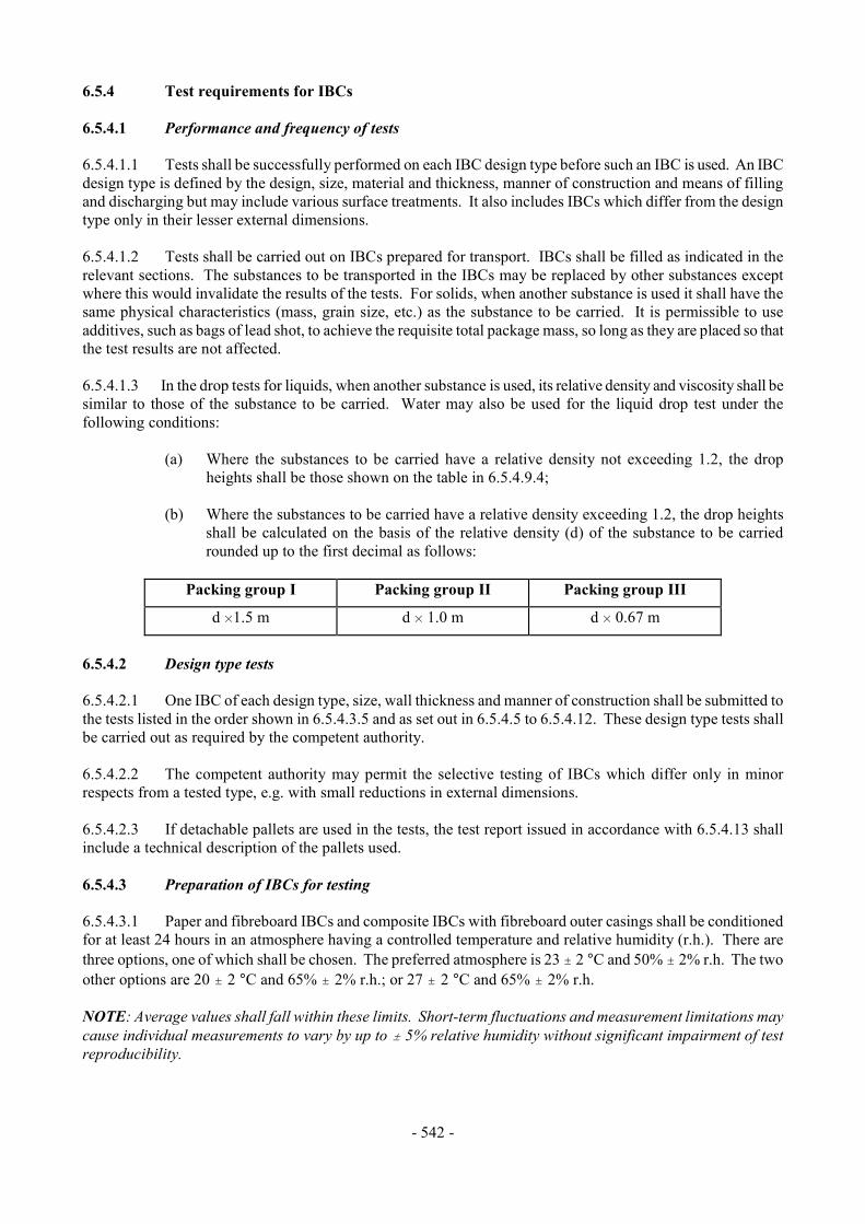
- 542 -
6.5.4 Test requirements for IBCs 6.5.4.1 Performance and frequency of tests 6.5.4.1.1 Tests shall be successfully performed on each IBC design type before such an IBC is used. An IBC design type is defined by the design, size, material and thickness, manner of construction and means of filling and discharging but may include various surface treatments. It also includes IBCs which differ from the design type only in their lesser external dimensions. 6.5.4.1.2 Tests shall be carried out on IBCs prepared for transport. IBCs shall be filled as indicated in the relevant sections. The substances to be transported in the IBCs may be replaced by other substances except where this would invalidate the results of the tests. For solids, when another substance is used it shall have the same physical characteristics (mass, grain size, etc.) as the substance to be carried. It is permissible to use additives, such as bags of lead shot, to achieve the requisite total package mass, so long as they are placed so that the test results are not affected. 6.5.4.1.3 In the drop tests for liquids, when another substance is used, its relative density and viscosity shall be similar to those of the substance to be carried. Water may also be used for the liquid drop test under the following conditions:
(a) Where the substances to be carried have a relative density not exceeding 1.2, the drop heights shall be those shown on the table in 6.5.4.9.4;
(b) Where the substances to be carried have a relative density exceeding 1.2, the drop heights
shall be calculated on the basis of the relative density (d) of the substance to be carried rounded up to the first decimal as follows:
Packing group I Packing group II Packing group III
d H1.5 m d H 1.0 m d H 0.67 m
6.5.4.2 Design type tests 6.5.4.2.1 One IBC of each design type, size, wall thickness and manner of construction shall be submitted to the tests listed in the order shown in 6.5.4.3.5 and as set out in 6.5.4.5 to 6.5.4.12. These design type tests shall be carried out as required by the competent authority. 6.5.4.2.2 The competent authority may permit the selective testing of IBCs which differ only in minor respects from a tested type, e.g. with small reductions in external dimensions. 6.5.4.2.3 If detachable pallets are used in the tests, the test report issued in accordance with 6.5.4.13 shall include a technical description of the pallets used. 6.5.4.3 Preparation of IBCs for testing 6.5.4.3.1 Paper and fibreboard IBCs and composite IBCs with fibreboard outer casings shall be conditioned for at least 24 hours in an atmosphere having a controlled temperature and relative humidity (r.h.). There are three options, one of which shall be chosen. The preferred atmosphere is 23 " 2 °C and 50% " 2% r.h. The two other options are 20 " 2 °C and 65% " 2% r.h.; or 27 " 2 °C and 65% " 2% r.h. NOTE: Average values shall fall within these limits. Short-term fluctuations and measurement limitations may cause individual measurements to vary by up to " 5% relative humidity without significant impairment of test reproducibility.

- 543 -
6.5.4.3.2 Additional steps shall be taken to ascertain that the plastics material used in the manufacture of rigid plastics IBCs (types 31H1 and 31H2) and composite IBCs (types 31HZ1 and 31HZ2) complies respectively with the requirements in 6.5.3.3.2 to 6.5.3.3.4 and 6.5.3.4.6 to 6.5.3.4.9. 6.5.4.3.3 This may be done, for example, by submitting sample IBCs to a preliminary test extending over a long period, for example six months, during which the samples would remain filled with the substances they are intended to contain or with substances which are known to have at least as severe a stress-cracking, weakening or molecular degradation influence on the plastics materials in question, and after which the samples shall be submitted to the applicable tests listed on the table in 6.5.4.3.5. 6.5.4.3.4 Where the behaviour of the plastics material has been established by other means, the above compatibility test may be dispensed with. 6.5.4.3.5 Design type tests required and sequential order
Type of IBC Bottom
lift
Top lift a
Stackingb
Leak-
proofness
Hydraulic pressure
Drop
Tear
Topple
Rightingc
Metal: 11A, 11B, 11N, 21A, 21B, 21N, 31A, 31B, 31N
1sta 1sta
2nd 2nd
3rd 3rd
-
4th
-
5th
4the 6the
- -
- -
- -
Flexibled
-
xc
x
-
-
X
x
x
x
Rigid plastics: 11H1, 11H2, 21H1, 21H2, 31H1, 31H2
1sta 1sta
2nd 2nd
3rd 3rd
-
4th
-
5th
4th 6th
- -
- -
- -
Composite: 11HZ1, 11HZ2, 21HZ1, 21HZ2, 31HZ1, 31HZ2
1sta 1sta
2nd 2nd
3rd 3rd
-
4th
-
5th
4the 6the
- -
- -
- -
Fibreboard
1st
-
2nd
-
-
3rd
-
-
-
Wooden
1st
-
2nd
-
-
3rd
-
-
-
a When IBCs are designed for this method of handling. b When IBCs are designed to be stacked. c When IBCs are designated to be lifted from the top or the side. d Required test indicated by x; an IBC which has passed one test may be used for other tests, in
any order. e Another IBC of the same design may be used for the drop test.
6.5.4.4 Bottom lift test 6.5.4.4.1 Applicability
For all fibreboard and wooden IBCs, and for all types of IBC which are fitted with means of lifting from the base, as a design type test. 6.5.4.4.2 Preparation of the IBC for test
The IBC shall be filled. A load shall be added and evenly distributed. The mass of the filled IBC and the load shall be 1.25 times the maximum permissible gross mass.

- 544 -
6.5.4.4.3 Method of testing
The IBC shall be raised and lowered twice by a lift truck with the forks centrally positioned and spaced at three quarters of the dimension of the side of entry (unless the points of entry are fixed). The forks shall penetrate to three quarters of the direction of entry. The test shall be repeated from each possible direction of entry. 6.5.4.4.4 Criteria for passing the test
No permanent deformation which renders the IBC, including the base pallet, if any, unsafe for transport and no loss of contents. 6.5.4.5 Top lift test 6.5.4.5.1 Applicability
For all types of IBC which are designed to be lifted from the top and for flexible IBCs designed to be lifted from the top or the side, as a design type test. 6.5.4.5.2 Preparation of the IBC for test
Metal, rigid plastics and composite IBCs shall be filled. A load shall be added and evenly distributed. The mass of the filled IBC and the load shall be twice the maximum permissible gross mass.
Flexible IBCs shall be filled to six times their maximum design load, the load being evenly
distributed. 6.5.4.5.3 Methods of testing
Metal and flexible IBCs shall be lifted in the manner for which they are designed until clear of the floor and maintained in that position for a period of five minutes.
Rigid plastics and composite IBCs shall be lifted:
(a) By each pair of diagonally opposite lifting devices, so that the hoisting forces are applied vertically, for a period of five minutes; and
(b) By each pair of diagonally opposite lifting devices, so that the hoisting forces are applied
toward the centre at 45° to the vertical, for a period of five minutes. 6.5.4.5.4 Other methods of top lift testing and preparation at least equally effective may be used for flexible IBCs. 6.5.4.5.5 Criteria for passing the test
(a) Metal, rigid plastics and composite IBCs: no permanent deformation which renders the IBC, including the base pallet, if any, unsafe for transport and no loss of contents;
(b) Flexible IBCs: no damage to the IBC or its lifting devices which renders the IBC unsafe for
transport or handling;

- 545 -
6.5.4.6 Stacking test 6.5.4.6.1 Applicability
For all types of IBC which are designed to be stacked on each other, as a design type test. 6.5.4.6.2 Preparation of the IBC for test
The IBC shall be filled to its maximum permissible gross mass. If the specific gravity of the product being used for testing makes this impracticable, the IBC shall be additionally loaded so that it is tested at its maximum permissible gross mass, the load being evenly distributed. 6.5.4.6.3 Methods of testing
(a) The IBC shall be placed on its base on level hard ground and subjected to a uniformly distributed superimposed test load (see 6.5.4.6.4). IBCs shall be subjected to the test load for a period of at least:
(i) 5 minutes, for metal IBCs; (ii) 28 days at 40 °C, for rigid plastics IBCs of types 11H2, 21H2 and 31H2 and for
composite IBCs with outer casings of plastics material which bear the stacking load (i.e., types 11HH1, 11HH2, 21HH1, 21HH2, 31HH1 and 31HH2);
(iii) 24 hours, for all other types of IBCs;
(b) The load shall be applied by one of the following methods:
(i) one or more IBCs of the same type filled to the maximum permissible gross mass stacked on the test IBC;
(ii) appropriate weights loaded onto either a flat plate or a reproduction of the base of the IBC, which is stacked on the test IBC.
6.5.4.6.4 Calculation of superimposed test load
The load to be placed on the IBC shall be 1.8 times the combined maximum permissible gross mass of the number of similar IBCs that may be stacked on top of the IBC during transport. 6.5.4.6.5 Criteria for passing the test
(a) All types of IBCs other than flexible IBCs: no permanent deformation which renders the IBC including the base pallet, if any, unsafe for transport and no loss of contents;
(b) Flexible IBCs: no deterioration of the body which renders the IBC unsafe for transport and
no loss of contents. 6.5.4.7 Leakproofness test 6.5.4.7.1 Applicability
For those types of IBCs used for liquids or for solids filled or discharged under pressure, as a design type test and periodic test.
- 546 -
6.5.4.7.2 Preparation of the IBC for test
The test shall be carried out before the fitting of any thermal insulation equipment. Vented closures shall either be replaced by similar non-vented closures or the vent shall be sealed. 6.5.4.7.3 Method of testing and pressure to be applied
The test shall be carried out for a period of at least 10 minutes using air at a gauge pressure of not less than 20 kPa (0.2 bar). The air tightness of the IBC shall be determined by a suitable method such as by air-pressure differential test or by immersing the IBC in water or, for metal IBCs, by coating the seams and joints with a soap solution. In the latter case a correction factor shall be applied for the hydrostatic pressure. Other methods at least equally effective may be used. 6.5.4.7.4 Criterion for passing the test
No leakage of air.
6.5.4.8 Hydraulic pressure test 6.5.4.8.1 Applicability
For those types of IBCs used for liquids or for solids filled or discharged under pressure, as a design type test. 6.5.4.8.2 Preparation of the IBC for test
The test shall be carried out before the fitting of any thermal insulation equipment. Pressure-relief devices shall be removed and their apertures plugged, or shall be rendered inoperative. 6.5.4.8.3 Method of testing
The test shall be carried out for a period of at least 10 minutes applying a hydraulic pressure not less than that indicated in 6.5.4.8.4. The IBCs shall not be mechanically restrained during the test. 6.5.4.8.4 Pressures to be applied 6.5.4.8.4.1 Metal IBCs:
(a) For IBCs of types 21A, 21B and 21N, for Packing Group I solids, a 250 kPa (2.5 bar) gauge pressure;
(b) For IBCs of types 21A, 21B, 21N, 31A, 31B and 31N, for Packing Groups II or III
substances, a 200 kPa (2 bar) gauge pressure;
(c) In addition, for IBCs of types 31A, 31B and 31N, a 65 kPa (0.65 bar) gauge pressure. This test shall be performed before the 200 kPa test.
6.5.4.8.4.2 Rigid plastics and composite IBCs:
(a) For IBCs of types 21H1, 2lH2, 21HZ1 and 21HZ2: 75 kPa (0.75 bar) (gauge);
(b) For IBCs of types 31H1, 31H2, 31HZ1 and 31HZ2: whichever is the greater of two values, the first as determined by one of the following methods:
- 547 -
(i) the total gauge pressure measured in the IBC (i.e. the vapour pressure of the filling substance and the partial pressure of the air or other inert gases, minus 100 kPa) at 55 °C multiplied by a safety factor of 1.5; this total gauge pressure shall be determined on the basis of a maximum degree of filling in accordance with 4.1.1.4 and a filling temperature of 15 °C;
(ii) 1.75 times the vapour pressure at 50 °C of the substance to be transported minus 100 kPa, but with a minimum test pressure of 100 kPa;
(iii) 1.5 times the vapour pressure at 55 °C of the substance to be transported minus 100 kPa, but with a minimum test pressure of 100 kPa;
and the second as determined by the following method: (iv) twice the static pressure of the substance to be transported, with a minimum of twice
the static pressure of water.
6.5.4.8.5 Criteria for passing the test(s) (a) For IBCs of types 21A, 21B, 21N, 31A, 31B and 31N, when subjected to the test pressure
specified in 6.5.4.8.4.1 (a) or (b): no leakage;
(b) For IBCs of types 31A, 31B and 31N, when subjected to the test pressure specified in 6.5.4.8.4.1 (c): neither permanent deformation which would render the IBC unsafe for transport, nor leakage;
(c) For rigid plastics and composite IBCs: no permanent deformation which would render the
IBC unsafe for transport and no leakage. 6.5.4.9 Drop test 6.5.4.9.1 Applicability
For all types of IBCs, as a design type test. 6.5.4.9.2 Preparation of the IBC for test
(a) Metal IBCs: the IBC shall be filled to not less than 95% of its capacity for solids or 98% for liquids in accordance with the design type. Pressure-relief devices shall be removed and their apertures plugged, or shall be rendered inoperative;
(b) Flexible IBCs: the IBC shall be filled to not less than 95% of its capacity and to its maximum
permissible gross mass, the contents being evenly distributed;
(c) Rigid plastics and composite IBCs: the IBC shall be filled to not less than 95% of its capacity for solids or 98% for liquids in accordance with the design type. Arrangements provided for pressure-relief may be removed and plugged or rendered inoperative. Testing of IBCs shall be carried out when the temperature of the test sample and its contents has been reduced to minus 18 °C or lower. Where test samples of composite IBCs are prepared in this way the conditioning specified in 6.5.4.3.1 may be waived. Test liquids shall be kept in the liquid state, if necessary by the addition of anti-freeze. This conditioning may be disregarded if the materials in question are of sufficient ductility and tensile strength at low temperatures;
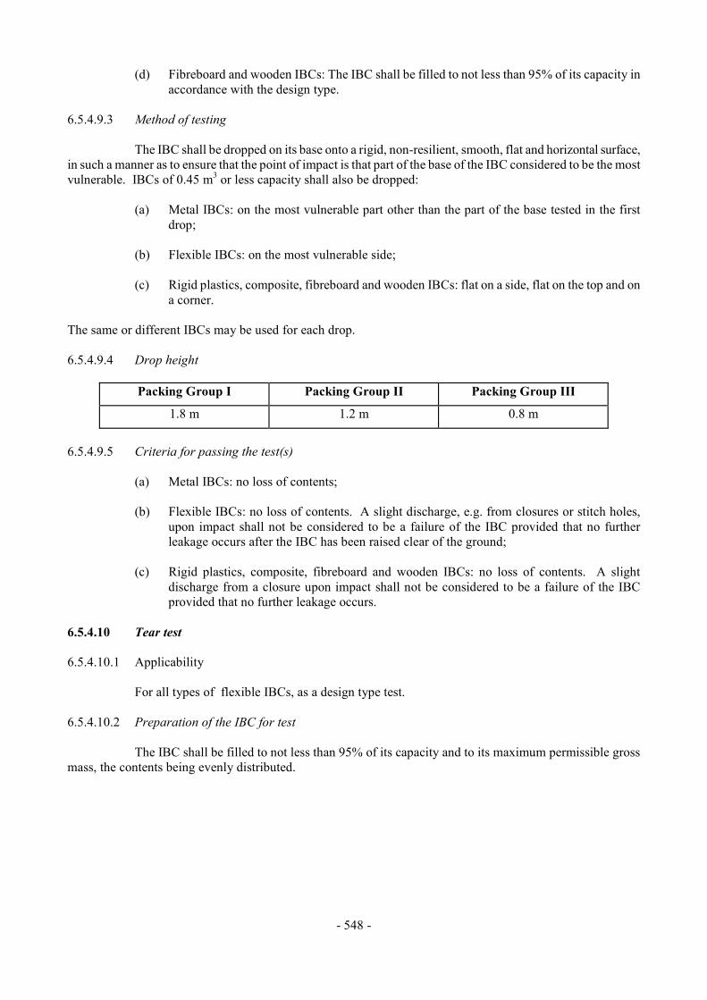
- 548 -
(d) Fibreboard and wooden IBCs: The IBC shall be filled to not less than 95% of its capacity in accordance with the design type.
6.5.4.9.3 Method of testing
The IBC shall be dropped on its base onto a rigid, non-resilient, smooth, flat and horizontal surface, in such a manner as to ensure that the point of impact is that part of the base of the IBC considered to be the most vulnerable. IBCs of 0.45 m3 or less capacity shall also be dropped:
(a) Metal IBCs: on the most vulnerable part other than the part of the base tested in the first drop;
(b) Flexible IBCs: on the most vulnerable side; (c) Rigid plastics, composite, fibreboard and wooden IBCs: flat on a side, flat on the top and on
a corner. The same or different IBCs may be used for each drop. 6.5.4.9.4 Drop height
Packing Group I Packing Group II Packing Group III
1.8 m 1.2 m 0.8 m
6.5.4.9.5 Criteria for passing the test(s)
(a) Metal IBCs: no loss of contents;
(b) Flexible IBCs: no loss of contents. A slight discharge, e.g. from closures or stitch holes, upon impact shall not be considered to be a failure of the IBC provided that no further leakage occurs after the IBC has been raised clear of the ground;
(c) Rigid plastics, composite, fibreboard and wooden IBCs: no loss of contents. A slight
discharge from a closure upon impact shall not be considered to be a failure of the IBC provided that no further leakage occurs.
6.5.4.10 Tear test 6.5.4.10.1 Applicability
For all types of flexible IBCs, as a design type test. 6.5.4.10.2 Preparation of the IBC for test
The IBC shall be filled to not less than 95% of its capacity and to its maximum permissible gross mass, the contents being evenly distributed.
- 549 -
6.5.4.10.3 Method of testing
Once the IBC is placed on the ground, a 100 mm knife score, completely penetrating the wall of a wide face, is made at a 45° angle to the principal axis of the IBC, halfway between the bottom surface and the top level of the contents. The IBC shall then be subjected to a uniformly distributed superimposed load equivalent to twice the maximum permissible gross mass. The load shall be applied for at least five minutes. An IBC which is designed to be lifted from the top or the side shall then, after removal of the superimposed load, be lifted clear of the floor and maintained in that position for a period of five minutes. 6.5.4.10.4 Criterion for passing the test
The cut shall not propagate more than 25% of its original length. 6.5.4.11 Topple test 6.5.4.11.1 Applicability
For all types of flexible IBCs, as a design type test. 6.5.4.11.2 Preparation of the IBC for test
The IBC shall be filled to not less than 95% of its capacity and to its maximum permissible gross mass, the contents being evenly distributed. 6.5.4.11.3 Method of testing
The IBC shall be caused to topple on to any part of its top on to a rigid, non-resilient, smooth, flat and horizontal surface. 6.5.4.11.4 Topple height
Packing group I Packing group II Packing group III
1.8 m 1.2 m 0.8 m
6.5.4.11.5 Criterion for passing the test
No loss of contents. A slight discharge, e.g. from closures or stitch holes, upon impact shall not be considered to be a failure of the IBC provided that no further leakage occurs. 6.5.4.12 Righting test 6.5.4.12.1 Applicability
For all flexible IBCs designed to be lifted from the top or side, as a design type test. 6.5.4.12.2 Preparation of the IBC for test
The IBC shall be filled to not less than 95% of its capacity and to its maximum permissible gross mass, the contents being evenly distributed.
- 550 -
6.5.4.12.3 Method of testing
The IBC, lying on its side, shall be lifted at a speed of at least 0.1 m/s to upright position, clear of the floor, by one lifting device or by two lifting devices when four are provided. 6.5.4.12.4 Criterion for passing the test
No damage to the IBC or its lifting devices which renders the IBC unsafe for transport or handling. 6.5.4.13 Test report 6.5.4.13.1 A test report containing at least the following particulars shall be drawn up and shall be available to the users of the IBC:
1. Name and address of the test facility 2. Name and address of applicant (where appropriate) 3. A unique test report identification 4. Date of the test report 5. Manufacturer of the IBC 6. Description of the IBC design type (e.g. dimensions, materials, closures, thickness, etc.)
including method of manufacture (e.g. blow moulding) and which may include drawing(s) and/or photograph(s)
7. Maximum capacity 8. Characteristics of test contents, e.g. viscosity and relative density for liquids and particle size
for solids 9. Test descriptions and results 10. The test report shall be signed with the name and status of the signatory
6.5.4.13.2 The test report shall contain statements that the IBC prepared as for transport was tested in accordance with the appropriate requirements of this Chapter and that the use of other packaging methods or components may render it invalid. A copy of the test report shall be available to the competent authority. 6.5.4.14 Testing of metal, rigid plastics and composite IBCs 6.5.4.14.1 These tests shall be carried out as required by the competent authority. 6.5.4.14.2 Each IBC shall correspond in all respects to its design type. 6.5.4.14.3 Each metal, rigid plastics and composite IBC for liquids, or for solids which are filled or discharged under pressure, shall be subjected to the leakproofness test, as an initial test (i.e., before the IBC is first used for transport), after repair and at intervals of not more than two and a half years. 6.5.4.14.4 The results of tests and the identity of the party performing the tests shall be recorded in test reports to be kept by the owner of the IBC at least until the date of the next test.

- 551 -
CHAPTER 6.6
REQUIREMENTS FOR THE CONSTRUCTION AND TESTING OF LARGE PACKAGINGS
6.6.1 General 6.6.1.1 The requirements of this Chapter do not apply to:
- Class 2, except articles including aerosols;
- Class 6.2, except clinical waste of UN 3291;
- Class 7 packages containing radioactive material. 6.6.1.2 Large packagings shall be manufactured and tested under a quality assurance programme which satisfies the competent authority in order to ensure that each manufactured packaging meets the requirements of this Chapter. 6.6.1.3 The specific requirements for large packagings in 6.6.4 are based on large packagings currently used. In order to take into account progress in science and technology, there is no objection to the use of large packagings having specifications different from those in 6.6.4 provided they are equally effective, acceptable to the competent authority and able successfully to withstand the tests described in 6.6.5. Methods of testing other than those described in these Regulations are acceptable provided they are equivalent. 6.6.1.4 Manufacturers and subsequent distributors of packagings shall provide information regarding procedures to be followed and a description of the types and dimensions of closures (including required gaskets) and any other components needed to ensure that packages as presented for transport are capable of passing the applicable performance tests of this Chapter. 6.6.2 Code for designating types of large packagings 6.6.2.1 The code used for large packagings consists of:
(a) Two Arabic numerals:
50 for rigid large packagings; or 51 for flexible large packagings; and
(b) Capital letters in Latin characters indicating the nature of the material, e.g. wood, steel etc.
The capital letters used shall be those shown in 6.1.2.6. 6.6.2.2 The letter “W” may follow the Large Packaging code. The letter “W” signifies that the large packaging, although of the same type indicated by the code, is manufactured to a specification different from those in 6.6.4 and is considered equivalent in accordance with the requirements in 6.6.1.3.

- 552 -
6.6.3 Marking 6.6.3.1 Primary marking. Each large packaging manufactured and intended for the use according to these Regulations shall bear durable and legible markings showing:
(a) The United Nations packaging symbol
;
For metal large packagings on which the marking is stamped or embossed, the capital letters "UN" may be applied instead of the symbol;
(b) The code "50" designating a large rigid packaging or "51" for flexible large packagings,
followed by the material type in accordance with 6.5.1.4.1 (b);
(c) A capital letter designating the packing group(s) for which the design type has been approved:
X for packing groups I, II and III Y for packing groups II and III Z for packing group III only;
(d) The month and year (last two digits) of manufacture;
(e) The State authorising the allocation of the mark; indicated by the distinguishing sign for
motor vehicles in international traffic;
(f) The name or symbol of the manufacturer and other identification of the large packagings as specified by the competent authority;
(g) The stacking test load in kg. For large packagings not designed for stacking the figure "0"
shall be shown;
(h) The maximum permissible gross mass in kilograms. The primary marking required above shall be applied in the sequence of the sub-paragraphs. Each element of the making applied in accordance with (a) to (h) shall be clearly separated, e.g. by a slash or space, so as to be easily identifiable. 6.6.3.2 Examples of the marking:
50 A/X/05 2500/1000
96/N/PQRS For a large steel packaging suitable for stacking; stacking load: 2500 kg; maximum gross mass: 1000 kg.
50 H/Y04 0/800
95/D/ABCD 987 For a large plastics packaging not suitable for stacking; maximum gross mass: 800 kg.
51H/Z/0697/S/1999 0/500
For a large flexible packaging not suitable for stacking; maximum gross mass: 500 kg.
- 553 -
6.6.4 Specific requirements for large packagings 6.6.4.1 Specific requirements for metal large packagings
50A steel 50B aluminium 50N metal (other than steel or aluminium)
6.6.4.1.1 The large packaging shall be made of suitable ductile metal in which the weldability has been fully demonstrated. Welds shall be skilfully made and afford complete safety. Low-temperature performance shall be taken into account when appropriate. 6.6.4.1.2 Care shall be taken to avoid damage by galvanic action due to the juxtaposition of dissimilar metals. 6.6.4.2 Specific requirements for flexible material large packagings
51H flexible plastics 51M flexible paper
6.6.4.2.1 The large packaging shall be manufactured from suitable materials. The strength of the material and the construction of the flexible large packagings shall be appropriate to its capacity and its intended use. 6.6.4.2.2 All materials used in the construction of flexible large packagings of types 51M shall, after complete immersion in water for not less than 24 hours, retain at least 85% of the tensile strength as measured originally on the material conditioned to equilibrium at 67% relative humidity or less. 6.6.4.2.3 Seams shall be formed by stitching, heat sealing, gluing or any equivalent method. All stitched seam-ends shall be secured. 6.6.4.2.4 Flexible large packagings shall provide adequate resistance to ageing and to degradation caused by ultraviolet radiation or the climatic conditions, or by the substance contained, thereby rendering them appropriate to their intended use. 6.6.4.2.5 For plastics flexible large packagings where protection against ultraviolet radiation is required, it shall be provided by the addition of carbon black or other suitable pigments or inhibitors. These additives shall be compatible with the contents and remain effective throughout the life of the large packaging. Where use is made of carbon black, pigments or inhibitors other than those used in the manufacture of the tested design type, re-testing may be waived if changes in the carbon black content, the pigment content or the inhibitor content do not adversely affect the physical properties of the material of construction. 6.6.4.2.6 Additives may be incorporated into the material of the large packaging to improve the resistance to ageing or to serve other purposes, provided that these do not adversely affect the physical or chemical properties of the material. 6.6.4.2.7 When filled, the ratio of height to width shall be not more than 2:1.

- 554 -
6.6.4.3 Specific requirements for plastics large packagings
50H rigid plastics 6.6.4.3.1 The large packaging shall be manufactured from suitable plastics material of known specifications and be of adequate strength in relation to its capacity and its intended use. The material shall be adequately resistant to ageing and to degradation caused by the substance contained or, where relevant, by ultraviolet radiation. Low temperature performance shall be taken into account when appropriate. Any permeation of the substance contained shall not constitute a danger under normal conditions of transport. 6.6.4.3.2 Where protection against ultraviolet radiation is required, it shall be provided by the addition of carbon black or other suitable pigments or inhibitors. These additives shall be compatible with the contents and remain effective throughout the life of the outer packaging. Where use is made of carbon black, pigments or inhibitors other than those used in the manufacture of the tested design type, re-testing may be waived if changes in the carbon black content, the pigment content or the inhibitor content do not adversely affect the physical properties of the material of construction. 6.6.4.3.3 Additives may be incorporated in the material of the large packaging to improve the resistance to ageing or to serve other purposes, provided that these do not adversely affect the physical or chemical properties of the material. 6.6.4.4 Specific requirements for fibreboard large packagings
50G rigid fibreboard 6.6.4.4.1 Strong and good quality solid or double-faced corrugated fibreboard (single or multiwall) shall be used, appropriate to the capacity of the large packagings and to their intended use. The water resistance of the outer surface shall be such that the increase in mass, as determined in a test carried out over a period of 30 minutes by the Cobb method of determining water absorption, is not greater than 155 g/m2 - see ISO 535:1991. It shall have proper bending qualities. Fibreboard shall be cut, creased without scoring, and slotted so as to permit assembly without cracking, surface breaks or undue bending. The fluting or corrugated fibreboard shall be firmly glued to the facings. 6.6.4.4.2 The walls, including top and bottom, shall have a minimum puncture resistance of 15 J measured according to ISO 3036:1975. 6.6.4.4.3 Manufacturing joins in the outer packaging of large packagings shall be made with an appropriate overlap and shall be taped, glued, stitched with metal staples or fastened by other means at least equally effective. Where joins are effected by gluing or taping, a water resistant adhesive shall be used. Metal staples shall pass completely through all pieces to be fastened and be formed or protected so that any inner liner cannot be abraded or punctured by them. 6.6.4.4.4 Any integral pallet base forming part of a large packaging or any detachable pallet shall be suitable for mechanical handling with the large packaging filled to its maximum permissible gross mass. 6.6.4.4.5 The pallet or integral base shall be designed so as to avoid any protrusion of the base of the large packaging that might be liable to damage in handling. 6.6.4.4.6 The body shall be secured to any detachable pallet to ensure stability in handling and transport. Where a detachable pallet is used, its top surface shall be free from sharp protrusions that might damage the large packaging. 6.6.4.4.7 Strengthening devices such as timber supports to increase stacking performance may be used but shall be external to the liner.

- 555 -
6.6.4.4.8 Where large packagings are intended for stacking, the bearing surface shall be such as to distribute the load in a safe manner. 6.6.4.5 Specific requirements for wooden large packagings
50C natural wood 50D plywood 50F reconstituted wood
6.6.4.5.1 The strength of the materials used and the method of construction shall be appropriate to the capacity and intended use of the large packagings. 6.6.4.5.2 Natural wood shall be well-seasoned, commercially dry and free from defects that would materially lessen the strength of any part of the large packagings. Each part of the large packagings shall consist of one piece or be equivalent thereto. Parts are considered equivalent to one piece when a suitable method of glued assembly is used as for instance Lindermann joint, tongue and groove joint, ship lap or rabbet joint; or butt joint with at least two corrugated metal fasteners at each joint, or when other methods at least equally effective are used. 6.6.4.5.3 Large packagings of plywood shall be at least 3-ply. They shall be made of well-seasoned rotary cut, sliced or sawn veneer, commercially dry and free from defects that would materially lessen the strength of the large packaging. All adjacent plies shall be glued with water resistant adhesive. Other suitable materials may be used with plywood for the construction of the large packaging. 6.6.4.5.4 Large packagings of reconstituted wood shall be made of water resistant reconstituted wood such as hardboard, particle board or other suitable type. 6.6.4.5.5 Large packagings shall be firmly nailed or secured to corner posts or ends or be assembled by equally suitable devices. 6.6.4.5.6 Any integral pallet base forming part of a large packaging or any detachable pallet shall be suitable for mechanical handling with the large packaging filled to its maximum permissible gross mass. 6.6.4.5.7 The pallet or integral base shall be designed so as to avoid any protrusion of the base of the large packaging that might be liable to damage in handling. 6.6.4.5.8 The body shall be secured to any detachable pallet to ensure stability in handling and transport. Where a detachable pallet is used, its top surface shall be free from sharp protrusions that might damage the large packaging. 6.6.4.5.9 Strengthening devices such as timber supports to increase stacking performance may be used but shall be external to the liner. 6.6.4.5.10 Where large packagings are intended for stacking, the bearing surface shall be such as to distribute the load in a safe manner. 6.6.5 Test requirements for large packagings 6.6.5.1 Performance and frequency of test 6.6.5.1.1 The design type of each large packaging shall be tested as provided in 6.6.5.3 in accordance with procedures established by the competent authority.
- 556 -
6.6.5.1.2 Tests shall be successfully performed on each large packaging design type before such a packaging is used. A large packaging design type is defined by the design, size, material and thickness, manner of construction and packing, but may include various surface treatments. It also includes large packagings which differ from the design type only in their lesser design height. 6.6.5.1.3 Tests shall be repeated on production samples at intervals established by the competent authority. For such tests on fibreboard large packagings, preparation at ambient conditions is considered equivalent to the provisions of 6.6.5.2.3. 6.6.5.1.4 Tests shall also be repeated after each modification which alters the design, material or manner of construction of large packagings. 6.6.5.1.5 The competent authority may permit the selective testing of large packagings that differ only in minor respects from a tested type, e.g. smaller sizes of inner packagings or inner packagings of lower net mass; and large packagings which are produced with small reductions in external dimension(s). 6.6.5.1.6 Where a large packaging has been successfully tested with different types of inner packagings, a variety of such different inner packagings may also be assembled in this large packaging. In addition, provided an equivalent level of performance is maintained, the following variations in inner packagings are allowed without further testing of the package:
(a) Inner packagings of equivalent or smaller size may be used provided: (i) The inner packagings are of similar design to the tested inner packagings (e.g. shape -
round, rectangular, etc); (ii) The material of construction of the inner packagings (glass, plastics, metal etc.) offers
resistance to impact and stacking forces equal to or greater than that of the originally tested inner packaging;
(iii) The inner packagings have the same or smaller openings and the closure is of similar design (e.g. screw cap, friction lid, etc);
(iv) Sufficient additional cushioning material is used to take up void spaces and to prevent significant movement of the inner packagings; and
(v) Inner packagings are oriented within the large packagings in the same manner as in the tested package;
(b) A lesser number of the tested inner packagings, or of the alternative types of inner
packagings identified in (a) above, may be used provided sufficient cushioning is added to fill the void space(s) and to prevent significant movement of the inner packagings.
6.6.5.1.7 The competent authority may at any time require proof, by tests in accordance with this section, that serially-produced large packagings meet the requirements of the design type tests. 6.6.5.1.8 Provided the validity of the test results is not affected and with the approval of the competent authority, several tests may be made on one sample.

- 557 -
6.6.5.2 Preparation for testing 6.6.5.2.1 Tests shall be carried out on large packagings prepared as for transport including the inner packagings or articles used. Inner packagings shall be filled to not less than 98% of their maximum capacity for liquids or 95% for solids. For large packagings where the inner packagings are designed to carry liquids and solids, separate testing is required for both liquid and solid contents. The substances in the inner packagings or the articles to be transported in the large packagings may be replaced by other material or articles except where this would invalidate the results of the tests. When other inner packagings or articles are used they shall have the same physical characteristics (mass, etc) as the inner packagings or articles to be carried. It is permissible to use additives, such as bags of lead shot, to achieve the requisite total package mass, so long as they are placed so that the test results are not affected. 6.6.5.2.2 Large packagings made of plastics materials and large packagings containing inner packagings of plastic materials - other than bags intended to contain solids or articles - shall be drop tested when the temperature of the test sample and its contents has been reduced to -18°C or lower. This conditioning may be disregarded if the materials in question are of sufficient ductility and tensile strength at low temperatures. Where test sample are prepared in this way, the conditioning in 6.6.5.2.3 may be waived. Test liquids shall be kept in the liquid state by the addition of anti-freeze if necessary. 6.6.5.2.3 Large packagings of fibreboard shall be conditioned for at least 24 hours in an atmosphere having a controlled temperature and relative humidity (r.h). There are three options, one of which shall be chosen. The preferred atmosphere is 23 " 2°C and 50% " 2% r.h. The two other options are: 20 " 2°C and 65% " 2% r.h.; or 27 " 2°C and 65% " 2% r.h. NOTE: Average values shall fall within these limits. Short-term fluctuations and measurement limitations may cause individual measurements to vary by up to " 5% relative humidity without significant impairment of test reproducibility. 6.6.5.3 Test requirements 6.6.5.3.1 Bottom lift test 6.6.5.3.1.1 Applicability For all types of large packagings which are fitted with means of lifting from the base, as a design type test. 6.6.5.3.1.2 Preparation of large packaging for test The large packaging shall be loaded to 1.25 times its maximum permissible gross mass, the load being evenly distributed. 6.6.5.3.1.3 Method of testing The large packaging shall be raised and lowered twice by a lift truck with the forks centrally positioned and spaced at three quarters of the dimension of the side of entry (unless the points of entry are fixed). The forks shall penetrate to three quarters of the direction of entry. The test shall be repeated from each possible direction of entry. 6.6.5.3.1.4 Criteria for passing the test No permanent deformation which renders the large packaging unsafe for transport and no loss of contents.

- 558 -
6.6.5.3.2 Top lift test 6.6.5.3.2.1 Applicability For types of large packagings which are intended to be lifted from the top and fitted with means of lifting, as a design type test. 6.6.5.3.2.2 Preparation of large packaging for test The large packaging shall be loaded to twice its maximum permissible gross mass. A flexible large packaging shall be loaded to six times its maximum permissible gross mass, the load being evenly distributed. 6.6.5.3.2.3 Method of testing The large packaging shall be lifted in the manner for which it is designed until clear of the floor and maintained in that position for a period of five minutes. 6.6.5.3.2.4 Criteria for passing the test No permanent deformation which renders the large packagings unsafe for transport and no loss of contents. 6.6.5.3.3 Stacking test 6.6.5.3.3.1 Applicability For all types of large packagings which are designed to be stacked on each other, as a design type test. 6.6.5.3.3.2 Preparation of large packaging for test The large packaging shall be filled to its maximum permissible gross mass. 6.6.5.3.3.3 Method of testing The large packaging shall be placed on its base on level hard ground and subjected to a uniformly distributed superimposed test load (see 6.6.5.3.3.4) for a period of at least five minutes: for large packagings of wood, fibreboard and plastics materials the period shall be 24 h. 6.6.5.3.3.4 Calculation of superimposed test load The load to be placed on the large packaging shall be 1.8 times the combined maximum permissible gross mass of the number of similar large packaging that may be stacked on top of the large packaging during transport. 6.6.5.3.3.5 Criteria for passing the test No permanent deformation which renders the large packaging unsafe for transport and no loss of contents.
- 559 -
6.6.5.3.4 Drop test 6.6.5.3.4.1 Applicability For all types of large packagings as a design type test. 6.6.5.3.4.2 Preparation of large packaging for testing The large packaging shall be filled in accordance with 6.6.5.2.1. 6.6.5.3.4.3 Method of testing The large packaging shall be dropped onto a rigid, non-resilient, smooth, flat and horizontal surface, in such a manner as to ensure that the point of impact is that part of the base of the large packaging considered to be the most vulnerable. 6.6.5.3.4.4 Drop height
Packing group I Packing group II Packing group III 1.8 m 1.2 m 0.8 m
NOTE: Packagings for substances and articles of Class 1, self-reactive substances of Division 4.1 and organic peroxides of Division 5.2 shall be tested at the Packing Group II performance level. 6.6.5.3.4.5 Criteria for passing the test 6.6.5.3.4.5.1 The large packaging shall not exhibit any damage liable to affect safety during transport. There shall be no leakage of the filling substance from inner packaging(s) or article(s). 6.6.5.3.4.5.2 No rupture is permitted in large packagings for articles of Class 1 which would permit the spillage of loose explosive substances or articles from the large packaging. 6.6.5.3.4.5.3 Where a large packaging undergoes a drop test, the sample passes the test if the entire contents are retained even if the closure is no longer sift-proof. 6.6.5.4 Certification and test report 6.6.5.4.1 In respect of each design type of large packaging a certificate and mark (as in 6.6.3) shall be issued attesting that the design type including its equipment meets the test requirements. 6.6.5.4.2 A test report containing at least the following particulars shall be drawn up and shall be available to the users of the large packaging: 1. Name and address of the test facility; 2. Name and address of applicant (where appropriate); 3. A unique test report identification; 4. Date of the test report; 5. Manufacturer of the large packaging; 6. Description of the large packaging design type (e.g. dimensions, materials, closures,
thickness, etc) and/or photograph(s); 7. Maximum capacity/maximum permissible gross mass;

- 560 -
8. Characteristics of test contents, e.g. types and descriptions of inner packagings or articles used;
9. Test descriptions and results; 10. The test report shall be signed with the name and status of the signatory. 6.6.5.4.3 The test report shall contain statements that the large packaging prepared as for transport was tested in accordance with the appropriate provisions of this Chapter and that the use of other packaging methods or components may render it invalid. A copy of the test report shall be available to the competent authority.

- 561 -
CHAPTER 6.7
REQUIREMENTS FOR THE DESIGN, CONSTRUCTION, INSPECTION AND TESTING OF PORTABLE TANKS
AND MULTIPLE-ELEMENT GAS CONTAINERS (MEGCs)
6.7.1 Application and general requirements 6.7.1.1 The requirements of this Chapter apply to portable tanks intended for the transport of dangerous goods of Classes 2, 3, 4, 5, 6, 7, 8 and 9, and to MEGCs intended for the transport of non-refrigerated gases of Class 2, by all modes of transport. In addition to the requirements of this Chapter, unless otherwise specified, the applicable requirements of the International Convention for Safe Containers (CSC) 1972, as amended, shall be fulfilled by any multimodal portable tank or MEGC which meets the definition of a "container" within the terms of that Convention. Additional requirements may apply to offshore portable tanks or MEGCs that are handled in open seas. 6.7.1.2 In recognition of scientific and technological advances, the technical requirements of this Chapter may be varied by alternative arrangements. These alternative arrangements shall offer a level of safety not less than that given by the requirements of this Chapter with respect to the compatibility with substances transported and the ability of the portable tank or MEGC to withstand impact, loading and fire conditions. For international transport, alternative arrangement portable tanks or MEGCs shall be approved by the applicable competent authorities. 6.7.1.3 When a substance is not assigned a portable tank instruction (T1 to T23, T50 or T75) in Column 10 of the Dangerous Goods List in Chapter 3.2, interim approval for transport may be issued by the competent authority of the country of origin. The approval shall be included in the documentation of the consignment and contain as a minimum the information normally provided in the portable tank instructions and the conditions under which the substance shall be transported. Appropriate measures shall be initiated by the competent authority to include the assignment in the Dangerous Goods List. 6.7.2 Requirements for the design, construction, inspection and testing of portable tanks intended for the transport of substances of Classes 3 to 9 6.7.2.1 Definitions For the purposes of this section:
Design pressure means the pressure to be used in calculations required by a recognized pressure vessel code. The design pressure shall be not less than the highest of the following pressures: (a) The maximum effective gauge pressure allowed in the shell during filling or discharge; or (b) The sum of: (i) the absolute vacour pressure (in bar) of the substance at 65 °C (at highest temperature
during filling, discharge or transport for elevated temperature substances transported above 65 °C), minus 1 bar; and

- 562 -
(ii) the partial pressure (in bar) of air or other gases in the ullage space being determined by a maximum ullage temperature of 65 °C and a liquid expansion due to an increase in mean bulk temperature of tr - tf (tf = filling temperature usually 15 °C; tr = 50 °C maximum mean bulk temperature); and
(iii) a head pressure determined on the basis of the dynamic forces specified in 6.7.2.2.12, but not less than 0.35 bar; or
(c) Two thirds of the minimum test pressure specified in the applicable portable tank instruction
in 4.2.5.2.6; Design temperature range for the shell shall be -40 °C to 50 °C for substances transported under ambient conditions. For substances handled under elevated temperature conditions the design temperature shall be not less than the maximum temperature of the substance during filling, discharge or transport. More severe design temperatures shall be considered for portable tanks subjected to severe climatic conditions; Leakproofness test means a test using gas subjecting the shell and its service equipment to an effective internal pressure of not less than 25% of the MAWP; Maximum allowable working pressure (MAWP) means a pressure that shall be not less than the highest of the following pressures measured at the top of the shell while in operating position: (a) The maximum effective gauge pressure allowed in the shell during filling or discharge; or (b) The maximum effective gauge pressure to which the shell is designed which shall be not less
than the sum of: (i) the absolute vapour pressure (in bar) of the substance at 65 °C (at the highest
temperature during filling, discharge or transport for elevated temperature substances transported above 65 °C), minus 1 bar; and
(ii) the partial pressure (in bar) of air or other gases in the ullage space being determined by a maximum ullage temperature of 65 °C and a liquid expansion due to an increase in mean bulk temperature of tr - tf (tf = filling temperature, usually 15 °C; tr = 50 °C, maximum mean bulk temperature);
Maximum permissible gross mass (MPGM) means the sum of the tare mass of the portable tank and the heaviest load authorized for transport; Mild steel means a steel with a guaranteed minimum tensile strength of 360 N/mm2 to 440 N/mm2 and a guaranteed minimum elongation at fracture conforming to 6.7.2.3.3.3; Portable tank means a multimodal tank having a capacity of more than 450 litres used for the transport of substances of Classes 3 to 9. The portable tank includes a shell fitted with service equipment and structural equipment necessary for the transport of dangerous substances. The portable tank shall be capable of being filled and discharged without the removal of its structural equipment. It shall possess stabilizing members external to the shell, and shall be capable of being lifted when full. It shall be designed primarily to be loaded onto a transport vehicle or ship and shall be equipped with skids, mountings or accessories to facilitate mechanical handling. Road tank-vehicles, rail tank-wagons, non-metallic tanks and intermediate bulk containers (IBCs) are not considered to fall within the definition for portable tanks; Reference steel means a steel with a tensile strength of 370 N/mm2 and an elongation at fracture of 27%; Service equipment means measuring instruments and filling, discharge, venting, safety, heating, cooling and insulating devices;
- 563 -
Shell means the part of the portable tank which retains the substance intended for transport (tank proper), including openings and their closures, but does not include service equipment or external structural equipment; Structural equipment means the reinforcing, fastening, protective and stabilizing members external to the shell; Test pressure means the maximum gauge pressure at the top of the shell during the hydraulic pressure test equal to not less than 1.5 times the design pressure. The minimum test pressure for portable tanks intended for specific substances is specified in the applicable portable tank instruction in 4.2.5.2.6. 6.7.2.2 General design and construction requirements 6.7.2.2.1 Shells shall be designed and constructed in accordance with the requirements of a pressure vessel code recognized by the competent authority. Shells shall be made of metallic materials suitable for forming. The materials shall in principle conform to national or international material standards. For welded shells only a material whose weldability has been fully demonstrated shall be used. Welds shall be skilfully made and afford complete safety. When the manufacturing process or the materials make it necessary, the shells shall be suitably heat-treated to guarantee adequate toughness in the weld and in the heat affected zones. In choosing the material, the design temperature range shall be taken into account with respect to risk of brittle fracture, to stress corrosion cracking and to resistance to impact. When fine grain steel is used, the guaranteed value of the yield strength shall be not more than 460 N/mm2 and the guaranteed value of the upper limit of the tensile strength shall be not more than 725 N/mm2 according to the material specification. Aluminium may only be used as a construction material when indicated in a portable tank special provision assigned to a specific substance in Column 11 of the Dangerous Goods List or when approved by the competent authority. When aluminium is authorized, it shall be insulated to prevent significant loss of physical properties when subjected to a heat load of 110 kW/m2 for a period of not less than 30 minutes. The insulation shall remain effective at all temperatures less than 649 °C and shall be jacketed with a material with a melting point of not less than 700 °C. Portable tank materials shall be suitable for the external environment in which they may be transported. 6.7.2.2.2 Portable tank shells, fittings, and pipework shall be constructed from materials which are:
(a) Substantially immune to attack by the substance(s) intended to be transported; or
(b) Properly passivated or neutralized by chemical reaction; or
(c) Lined with corrosion-resistant material directly bonded to the shell or attached by equivalent means.
6.7.2.2.3 Gaskets shall be made of materials not subject to attack by the substance(s) intended to be transported. 6.7.2.2.4 When shells are lined, the lining shall be substantially immune to attack by the substance(s) intended to be transported, homogeneous, non porous, free from perforations, sufficiently elastic and compatible with the thermal expansion characteristics of the shell. The lining of every shell, shell fittings and piping shall be continuous, and shall extend around the face of any flange. Where external fittings are welded to the tank, the lining shall be continuous through the fitting and around the face of external flanges. 6.7.2.2.5 Joints and seams in the lining shall be made by fusing the material together or by other equally effective means. 6.7.2.2.6 Contact between dissimilar metals which could result in damage by galvanic action shall be avoided.

- 564 -
6.7.2.2.7 The materials of the portable tank, including any devices, gaskets, linings and accessories, shall not adversely affect the substance(s) intended to be transported in the portable tank. 6.7.2.2.8 Portable tanks shall be designed and constructed with supports to provide a secure base during transport and with suitable lifting and tie-down attachments. 6.7.2.2.9 Portable tanks shall be designed to withstand, without loss of contents, at least the internal pressure due to the contents, and the static, dynamic and thermal loads during normal conditions of handling and transport. The design shall demonstrate that the effects of fatigue, caused by repeated application of these loads through the expected life of the portable tank, have been taken into account. 6.7.2.2.9.1 For portable tanks that are intended for use offshore, the dynamic stresses imposed by handling in open seas shall be taken into account. 6.7.2.2.10 A shell which is to be equipped with a vacuum-relief device shall be designed to withstand, without permanent deformation, an external pressure of not less than 0.21 bar above the internal pressure. The vacuum-relief device shall be set to relieve at a vacuum setting not greater than minus 0.21 bar unless the shell is designed for a higher external over pressure, in which case the vacuum-relief pressure of the device to be fitted shall be not greater than the tank design vacuum pressure. A shell used for the transport of solid substances of packing groups II or III only, which do not liquefy during transport, may be designed for a lower external pressure, subject to competent authority approval. In this case, the vacuum-relief device shall be set to relieve at this lower pressure. A shell that is not to be fitted with a vacuum-relief device shall be designed to withstand, without permanent deformation, an external pressure of not less than 0.4 bar above the internal pressure. 6.7.2.2.11 Vacuum-relief devices used on portable tanks intended for the transport of substances meeting the flash point criteria of Class 3, including elevated temperature substances transported at or above their flash point, shall prevent the immediate passage of flame into the shell, or the portable tank shall have a shell capable of withstanding, without leakage an internal explosion resulting from the passage of flame into the shell. 6.7.2.2.12 Portable tanks and their fastenings shall, under the maximum permissible load, be capable of absorbing the following separately applied static forces: (a) In the direction of travel: twice the MPGM multiplied by the acceleration due to gravity (g)*;
(b) Horizontally at right angles to the direction of travel: the MPGM (when the direction of travel is not clearly determined, the forces shall be equal to twice the MPGM) multiplied by the acceleration due to gravity (g)*;
(c) Vertically upwards: the MPGM multiplied by the acceleration due to gravity (g)*; and (d) Vertically downwards: twice the MPGM (total loading including the effect of gravity)
multiplied by the acceleration due to gravity (g)*. 6.7.2.2.13 Under each of the forces in 6.7.2.2.12, the safety factor to be observed shall be as follows: (a) For metals having a clearly defined yield point, a safety factor of 1.5 in relation to the
guaranteed yield strength; or
* For calculation purposes g = 9.81 m/s2.
- 565 -
(b) For metals with no clearly defined yield point, a safety factor of 1.5 in relation to the guaranteed 0.2% proof strength and, for austenitic steels, the 1% proof strength.
6.7.2.2.14 The values of yield strength or proof strength shall be the values according to national or international material standards. When austenitic steels are used, the specified minimum values of yield strength or proof strength according to the material standards may be increased by up to 15% when these greater values are attested in the material inspection certificate. When no material standard exists for the metal in question, the value of yield strength or proof strength used shall be approved by the competent authority. 6.7.2.2.15 Portable tanks shall be capable of being electrically earthed when intended for the transport of substances meeting the flash point criteria of Class 3 including elevated temperature substances transported at or above their flash point. Measures shall be taken to prevent dangerous electrostatic discharge. 6.7.2.2.16 When required for certain substances by the applicable portable tank instruction indicated in Column 10 of the Dangerous Goods List and described in 4.2.5.2.6, or by a portable tank special provision indicated in Column 11 and described in 4.2.5.3 of the Dangerous Goods List, portable tanks shall be provided with additional protection, which may take the form of additional shell thickness or a higher test pressure, the additional shell thickness or higher test pressure being determined in the light of the inherent risks associated with the transport of the substances concerned. 6.7.2.2.17 Thermal insulation directly in contact with the shell intended for substances transported at elevated temperature shall have an ignition temperature at least 50 °C higher than the maximum design temperature of the tank. 6.7.2.3 Design criteria 6.7.2.3.1 Shells shall be of a design capable of being stress-analysed mathematically or experimentally by resistance strain gauges, or by other methods approved by the competent authority. 6.7.2.3.2 Shells shall be designed and constructed to withstand a hydraulic test pressure not less than 1.5 times the design pressure. Specific requirements are laid down for certain substances in the applicable portable tank instruction indicated in Column 10 of the Dangerous Goods List and described in 4.2.5.2.6 or by a portable tank special provision indicated in Column 11 of the Dangerous Goods List and described in 4.2.5.3. Attention is drawn to the minimum shell thickness requirements for these tanks specified in 6.7.2.4.1 to 6.7.2.4.10. 6.7.2.3.3 For metals exhibiting a clearly defined yield point or characterized by a guaranteed proof strength (0.2% proof strength, generally, or 1% proof strength for austenitic steels) the primary membrane stress σ (sigma) in the shell shall not exceed 0.75 Re or 0.50 Rm, whichever is lower, at the test pressure, where: Re = yield strength in N/mm2, or 0.2% proof strength or, for austenitic steels, 1% proof
strength; Rm = minimum tensile strength in N/mm2. 6.7.2.3.3.1 The values of Re and Rm to be used shall be the specified minimum values according to national or international material standards. When austenitic steels are used, the specified minimum values for Re and Rm according to the material standards may be increased by up to 15% when greater values are attested in the material inspection certificate. When no material standard exists for the metal in question, the values of Re and Rm used shall be approved by the competent authority or its authorized body.
- 566 -
6.7.2.3.3.2 Steels which have a Re/Rm ratio of more than 0.85 are not allowed for the construction of welded shells. The values of Re and Rm to be used in determining this ratio shall be the values specified in the material inspection certificate. 6.7.2.3.3.3 Steels used in the construction of shells shall have an elongation at fracture, in %, of not less than 10 000/Rm with an absolute minimum of 16% for fine grain steels and 20% for other steels. Aluminium and aluminium alloys used in the construction of shells shall have an elongation at fracture, in %, of not less than 10 000/6Rm with an absolute minimum of 12%. 6.7.2.3.3.4 For the purpose of determining actual values for materials, it shall be noted that for sheet metal, the axis of the tensile test specimen shall be at right angles (transversely) to the direction of rolling. The permanent elongation at fracture shall be measured on test specimens of rectangular cross sections in accordance with ISO 6892:1998 using a 50 mm gauge length. 6.7.2.4 Minimum shell thickness 6.7.2.4.1 The minimum shell thickness shall be the greater thickness based on:
(a) The minimum thickness determined in accordance with the requirements of 6.7.2.4.2 to 6.7.2.4.10;
(b) The minimum thickness determined in accordance with the recognized pressure vessel code
including the requirements in 6.7.2.3; and (c) The minimum thickness specified in the applicable portable tank instruction indicated in
Column 10 of the Dangerous Goods List and described in 4.2.5.2.6, or by a portable tank special provision indicated in Column 11 of the Dangerous Goods List and described in 4.2.5.3.
6.7.2.4.2 The cylindrical portions, ends (heads) and manhole covers of shells not more than 1.80 m in diameter shall be not less than 5 mm thick in the reference steel or of equivalent thickness in the metal to be used. Shells more than 1.80 m in diameter shall be not less than 6 mm thick in the reference steel or of equivalent thickness in the metal to be used, except that for powdered or granular solid substances of Packing Group II or III the minimum thickness requirement may be reduced to not less than 5 mm thick in the reference steel or of equivalent thickness in the metal to be used. 6.7.2.4.3 When additional protection against shell damage is provided, portable tanks with test pressures less than 2.65 bar, may have the minimum shell thickness reduced, in proportion to the protection provided, as approved by the competent authority. However, shells not more than 1.80 m in diameter shall be not less than 3 mm thick in the reference steel or of equivalent thickness in the metal to be used. Shells more than 1.80 m in diameter shall be not less than 4 mm thick in the reference steel or of equivalent thickness in the metal to be used. 6.7.2.4.4 The cylindrical portions, ends (heads) and manhole covers of all shells shall be not less than 3 mm thick regardless of the material of construction. 6.7.2.4.5 The additional protection referred to in 6.7.2.4.3 may be provided by overall external structural protection, such as suitable "sandwich" construction with the outer sheathing (jacket) secured to the shell, double wall construction or by enclosing the shell in a complete framework with longitudinal and transverse structural members.
- 567 -
6.7.2.4.6 The equivalent thickness of a metal other than the thickness prescribed for the reference steel in 6.7.2.4.3 shall be determined using the following formula:
ee
Rm x A1
03
1 1
214=
.
where:
e1 = required equivalent thickness (in mm) of the metal to be used; e 0 = minimum thickness (in mm) of the reference steel specified in the applicable portable
tank instruction indicated in Column 10 of the Dangerous Goods List and described in 4.2.5.2.6 or by a portable tank special provision indicated in Column 11 of the Dangerous Goods List and described in 4.2.5.3;
Rm1 = guaranteed minimum tensile strength (in N/mm2) of the metal to be used (see 6.7.2.3.3);
A1 = guaranteed minimum elongation at fracture (in %) of the metal to be used according to national or international standards.
6.7.2.4.7 When in the applicable portable tank instruction in 4.2.5.2.6, a minimum thickness of 8 mm or 10 mm is specified, it shall be noted that these thicknesses are based on the properties of the reference steel and a shell diameter of 1.80 m. When a metal other than mild steel (see 6.7.2.1) is used or the shell has a diameter of more than 1.80 m, the thickness shall be determined using the following formula:
e e dRm x A
l1
0
1 13
21418
=.
.
where:
e1 = required equivalent thickness (in mm) of the metal to be used; e0 = minimum thickness (in mm) of the reference steel specified in the applicable portable
tank instruction indicated in Column 10 of the Dangerous Goods List and described in 4.2.5.2.6 or by a portable tank special provision indicated in Column 11 of the Dangerous Goods List and described in 4.2.5.3;
d1 = diameter of the shell (in m), but not less than 1.80 m; Rm1 = guaranteed minimum tensile strength (in N/mm2) of the metal to be used
(see 6.7.2.3.3); A1 = guaranteed minimum elongation at fracture (in %) of the metal to be used according to
national or international standards. 6.7.2.4.8 In no case shall the wall thickness be less than that prescribed in 6.7.2.4.2, 6.7.2.4.3 and 6.7.2.4.4. All parts of the shell shall have a minimum thickness as determined by 6.7.2.4.2 to 6.7.2.4.4. This thickness shall be exclusive of any corrosion allowance. 6.7.2.4.9 When mild steel is used (see 6.7.2.1), calculation using the formula in 6.7.2.4.6 is not required. 6.7.2.4.10 There shall be no sudden change of plate thickness at the attachment of the ends (heads) to the cylindrical portion of the shell.
- 568 -
6.7.2.5 Service equipment 6.7.2.5.1 Service equipment shall be so arranged as to be protected against the risk of being wrenched off or damaged during handling and transport. When the connection between the frame and the shell allows relative movement between the sub-assemblies, the equipment shall be so fastened as to permit such movement without risk of damage to working parts. The external discharge fittings (pipe sockets, shut-off devices), the internal stop-valve and its seating shall be protected against the danger of being wrenched off by external forces (for example using shear sections). The filling and discharge devices (including flanges or threaded plugs) and any protective caps shall be capable of being secured against unintended opening. 6.7.2.5.2 All openings in the shell, intended for filling or discharging the portable tank shall be fitted with a manually operated stop-valve located as close to the shell as reasonably practicable. Other openings, except for openings leading to venting or pressure-relief devices, shall be equipped with either a stop-valve or another suitable means of closure located as close to the shell as reasonably practicable. 6.7.2.5.3 All portable tanks shall be fitted with a manhole or other inspection openings of a suitable size to allow for internal inspection and adequate access for maintenance and repair of the interior. Compartmented portable tanks shall have a manhole or other inspection openings for each compartment. 6.7.2.5.4 As far as reasonably practicable, external fittings shall be grouped together. For insulated portable tanks, top fittings shall be surrounded by a spill collection reservoir with suitable drains. 6.7.2.5.5 Each connection to a portable tank shall be clearly marked to indicate its function. 6.7.2.5.6 Each stop-valve or other means of closure shall be designed and constructed to a rated pressure not less than the MAWP of the shell taking into account the temperatures expected during transport. All stop-valves with screwed spindles shall close by a clockwise motion of the handwheel. For other stop-valves the position (open and closed) and direction of closure shall be clearly indicated. All stop-valves shall be designed to prevent unintentional opening. 6.7.2.5.7 No moving parts, such as covers, components of closures, etc., shall be made of unprotected corrodible steel when they are liable to come into frictional or percussive contact with aluminium portable tanks intended for the transport of substances meeting the flash point criteria of Class 3 including elevated temperature substances transported at or above their flash point. 6.7.2.5.8 Piping shall be designed, constructed and installed so as to avoid the risk of damage due to thermal expansion and contraction, mechanical shock and vibration. All piping shall be of a suitable metallic material. Welded pipe joints shall be used wherever possible. 6.7.2.5.9 Joints in copper tubing shall be brazed or have an equally strong metal union. The melting point of brazing materials shall be no lower than 525 °C. The joints shall not decrease the strength of the tubing as may happen when cutting threads. 6.7.2.5.10 The burst pressure of all piping and pipe fittings shall be not less than the highest of four times the MAWP of the shell or four times the pressure to which it may be subjected in service by the action of a pump or other device (except pressure-relief devices). 6.7.2.5.11 Ductile metals shall be used in the construction of valves and accessories. 6.7.2.5.12 The heating system shall be designed or controlled so that a substance cannot reach a temperature at which the pressure in the tank exceeds its MAWP or causes other hazards (e.g. dangerous thermal decomposition).

- 569 -
6.7.2.5.13 The heating system shall be designed or controlled so that power for internal heating elements shall not be available unless the heating elements are completely submerged. The temperature at the surface of the heating elements for internal heating equipment, or the temperature at the shell for external heating equipment shall, in no case, exceed 80% of the autoignition temperature (in °C) of the substance transported. 6.7.2.5.14 If an electrical heating system is installed inside the tank, it shall be equipped with an earth leakage circuit breaker with a releasing current of less than 100 mA. 6.7.2.5.15 Electrical switch cabinets mounted to tanks shall not have a direct connection to the tank interior and shall provide protection of at least the equivalent of type IP56 according to IEC 144 or IEC 529. 6.7.2.6 Bottom openings 6.7.2.6.1 Certain substances shall not be transported in portable tanks with bottom openings. When the applicable portable tank instruction identified in Column 10 of the Dangerous Goods List and described in 4.2.4.2.6 indicates that bottom openings are prohibited there shall be no openings below the liquid level of the shell when it is filled to its maximum permissible filling limit. When an existing opening is closed it shall be accomplished by internally and externally welding one plate to the shell. 6.7.2.6.2 Bottom discharge outlets for portable tanks carrying certain solid, crystallizable or highly viscous substances shall be equipped with not less than two serially fitted and mutually independent shut-off devices. The design of the equipment shall be to the satisfaction of the competent authority or its authorized body and shall include:
(a) An external stop-valve fitted as close to the shell as reasonably practicable; and
(b) A liquid tight closure at the end of the discharge pipe, which may be a bolted blank flange or a screw cap.
6.7.2.6.3 Every bottom discharge outlet, except as provided in 6.7.2.6.2, shall be equipped with three serially fitted and mutually independent shut-off devices. The design of the equipment shall be to the satisfaction of the competent authority or its authorized body and include:
(a) A self-closing internal stop-valve, that is a stop-valve within the shell or within a welded flange or its companion flange, such that:
(i) The control devices for the operation of the valve are designed so as to prevent any
unintended opening through impact or other inadvertent act; (ii) The valve may be operable from above or below; (iii) If possible, the setting of the valve (open or closed) shall be capable of being verified
from the ground; (iv) Except for portable tanks having a capacity of not more than 1,000 litres, it shall be
possible to close the valve from an accessible position of the portable tank that is remote from the valve itself; and
(v) The valve shall continue to be effective in the event of damage to the external device for controlling the operation of the valve;
(b) An external stop-valve fitted as close to the shell as reasonably practicable; and
(c) A liquid tight closure at the end of the discharge pipe, which may be a bolted blank flange or
a screw cap.

- 570 -
6.7.2.6.4 For a lined shell, the internal stop-valve required by 6.7.2.6.3 (a) may be replaced by an additional external stop-valve. The manufacturer shall satisfy the requirements of the competent authority or its authorized body. 6.7.2.7 Safety relief devices 6.7.2.7.1 All portable tanks shall be fitted with at least one pressure-relief device. All relief devices shall be designed, constructed and marked to the satisfaction of the competent authority or its authorized body. 6.7.2.8 Pressure-relief devices 6.7.2.8.1 Every portable tank with a capacity not less than 1,900 litres and every independent compartment of a portable tank with a similar capacity, shall be provided with one or more pressure-relief devices of the spring-loaded type and may in addition have a frangible disc or fusible element in parallel with the spring-loaded devices except when prohibited by reference to 6.7.2.8.3 in the applicable portable tank instruction in 4.2.4.2.6. The pressure-relief devices shall have sufficient capacity to prevent rupture of the shell due to over pressurization or vacuum resulting from filling, discharging, or from heating of the contents. 6.7.2.8.2 Pressure-relief devices shall be designed to prevent the entry of foreign matter, the leakage of liquid and the development of any dangerous excess pressure. 6.7.2.8.3 When required for certain substances by the applicable portable tank instruction identified in Column 10 of the Dangerous Goods List and described in 4.2.4.2.6, portable tanks shall have a pressure-relief device approved by the competent authority. Unless a portable tank in dedicated service is fitted with an approved relief device constructed of materials compatible with the load, the relief device shall comprise a frangible disc preceding a spring-loaded pressure-relief device. When a frangible disc is inserted in series with the required pressure-relief device, the space between the frangible disc and the pressure-relief device shall be provided with a pressure gauge or suitable tell-tale indicator for the detection of disc rupture, pinholing, or leakage which could cause a malfunction of the pressure-relief system. The frangible disc shall rupture at a nominal pressure 10% above the start to discharge pressure of the relief device. 6.7.2.8.4 Every portable tank with a capacity less than 1,900 litres shall be fitted with a pressure-relief device which may be a frangible disc when this disc complies with the requirements of 6.7.2.11.1. When no spring-loaded pressure-relief device is used, the frangible disc shall be set to rupture at a nominal pressure equal to the test pressure. 6.7.2.8.5 When the shell is fitted for pressure discharge, the inlet line shall be provided with a suitable pressure-relief device set to operate at a pressure not higher than the MAWP of the shell, and a stop-valve shall be fitted as close to the shell as reasonably practicable. 6.7.2.9 Setting of pressure-relief devices 6.7.2.9.1 It shall be noted that the pressure-relief devices shall operate only in conditions of excessive rise in temperature, since the shell shall not be subject to undue fluctuations of pressure during normal conditions of transport (see 6.7.2.12.2). 6.7.2.9.2 The required pressure-relief device shall be set to start-to-discharge at a nominal pressure of five-sixths of the test pressure for shells having a test pressure of not more than 4.5 bar and 110% of two-thirds of the test pressure for shells having a test pressure of more than 4.5 bar. After discharge the device shall close at a pressure not more than 10% below the pressure at which the discharge starts. The device shall remain closed at all lower pressures. This requirement does not prevent the use of vacuum-relief or combination pressure-relief and vacuum-relief devices.
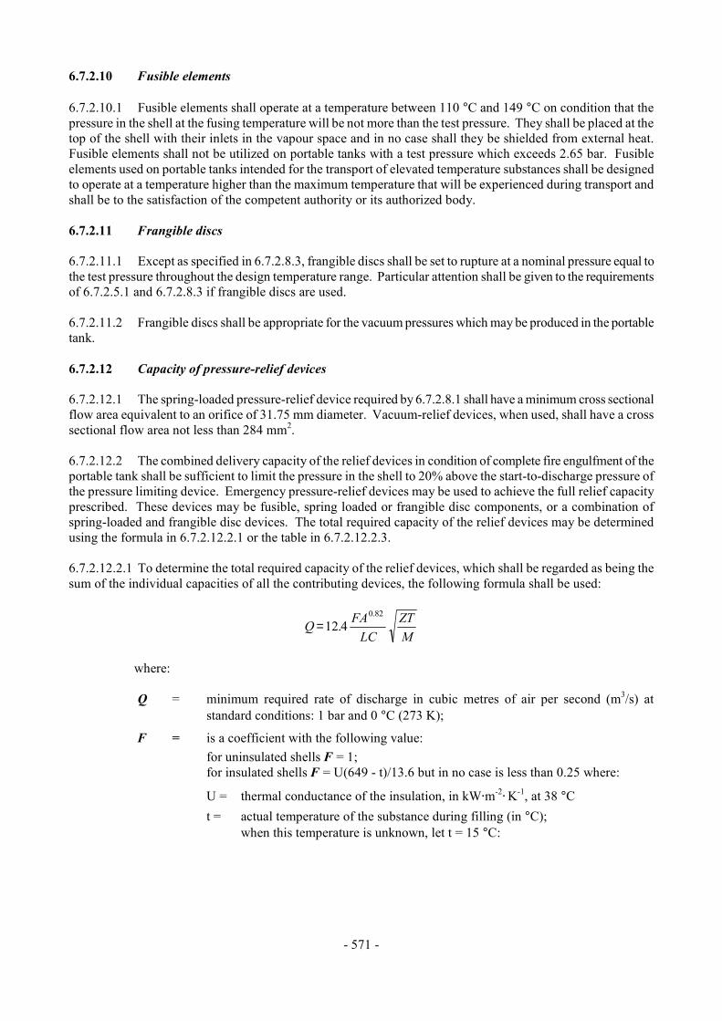
- 571 -
6.7.2.10 Fusible elements 6.7.2.10.1 Fusible elements shall operate at a temperature between 110 °C and 149 °C on condition that the pressure in the shell at the fusing temperature will be not more than the test pressure. They shall be placed at the top of the shell with their inlets in the vapour space and in no case shall they be shielded from external heat. Fusible elements shall not be utilized on portable tanks with a test pressure which exceeds 2.65 bar. Fusible elements used on portable tanks intended for the transport of elevated temperature substances shall be designed to operate at a temperature higher than the maximum temperature that will be experienced during transport and shall be to the satisfaction of the competent authority or its authorized body. 6.7.2.11 Frangible discs 6.7.2.11.1 Except as specified in 6.7.2.8.3, frangible discs shall be set to rupture at a nominal pressure equal to the test pressure throughout the design temperature range. Particular attention shall be given to the requirements of 6.7.2.5.1 and 6.7.2.8.3 if frangible discs are used. 6.7.2.11.2 Frangible discs shall be appropriate for the vacuum pressures which may be produced in the portable tank. 6.7.2.12 Capacity of pressure-relief devices 6.7.2.12.1 The spring-loaded pressure-relief device required by 6.7.2.8.1 shall have a minimum cross sectional flow area equivalent to an orifice of 31.75 mm diameter. Vacuum-relief devices, when used, shall have a cross sectional flow area not less than 284 mm2. 6.7.2.12.2 The combined delivery capacity of the relief devices in condition of complete fire engulfment of the portable tank shall be sufficient to limit the pressure in the shell to 20% above the start-to-discharge pressure of the pressure limiting device. Emergency pressure-relief devices may be used to achieve the full relief capacity prescribed. These devices may be fusible, spring loaded or frangible disc components, or a combination of spring-loaded and frangible disc devices. The total required capacity of the relief devices may be determined using the formula in 6.7.2.12.2.1 or the table in 6.7.2.12.2.3. 6.7.2.12.2.1 To determine the total required capacity of the relief devices, which shall be regarded as being the sum of the individual capacities of all the contributing devices, the following formula shall be used:
Q FALC
ZTM
=12 40.82
.
where:
Q = minimum required rate of discharge in cubic metres of air per second (m3/s) at
standard conditions: 1 bar and 0 °C (273 K);
F = is a coefficient with the following value: for uninsulated shells F = 1; for insulated shells F = U(649 - t)/13.6 but in no case is less than 0.25 where:
U = thermal conductance of the insulation, in kW@m-2@ K-1, at 38 °C
t = actual temperature of the substance during filling (in °C); when this temperature is unknown, let t = 15 °C:
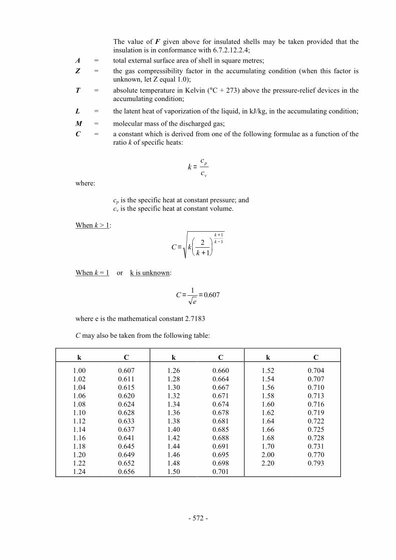
- 572 -
The value of F given above for insulated shells may be taken provided that the insulation is in conformance with 6.7.2.12.2.4;
A = total external surface area of shell in square metres; Z = the gas compressibility factor in the accumulating condition (when this factor is
unknown, let Z equal 1.0); T = absolute temperature in Kelvin (°C + 273) above the pressure-relief devices in the
accumulating condition;
L = the latent heat of vaporization of the liquid, in kJ/kg, in the accumulating condition;
M = molecular mass of the discharged gas; C = a constant which is derived from one of the following formulae as a function of the
ratio k of specific heats:
kcc
p
v=
where:
cp is the specific heat at constant pressure; and cv is the specific heat at constant volume.
When k > 1:
C kk
kk
=+
+−2
1
11
When k = 1 or k is unknown:
Ce
= =1 0 607.
where e is the mathematical constant 2.7183
C may also be taken from the following table:
k
C
k
C
k
C
1.00 1.02 1.04 1.06 1.08 1.10 1.12 1.14 1.16 1.18 1.20 1.22 1.24
0.607 0.611 0.615 0.620 0.624 0.628 0.633 0.637 0.641 0.645 0.649 0.652 0.656
1.26 1.28 1.30 1.32 1.34 1.36 1.38 1.40 1.42 1.44 1.46 1.48 1.50
0.660 0.664 0.667 0.671 0.674 0.678 0.681 0.685 0.688 0.691 0.695 0.698 0.701
1.52 1.54 1.56 1.58 1.60 1.62 1.64 1.66 1.68 1.70 2.00 2.20
0.704 0.707 0.710 0.713 0.716 0.719 0.722 0.725 0.728 0.731 0.770 0.793
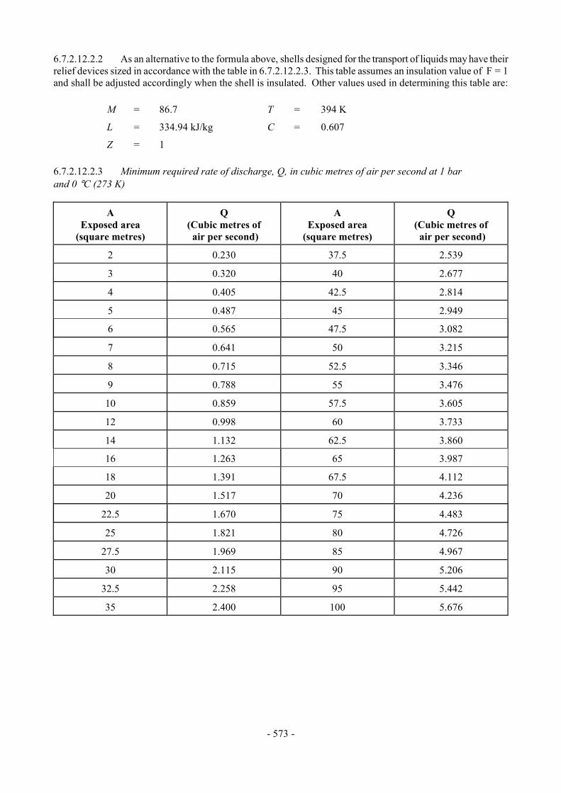
- 573 -
6.7.2.12.2.2 As an alternative to the formula above, shells designed for the transport of liquids may have their relief devices sized in accordance with the table in 6.7.2.12.2.3. This table assumes an insulation value of F = 1 and shall be adjusted accordingly when the shell is insulated. Other values used in determining this table are: M = 86.7 T = 394 K
L = 334.94 kJ/kg C = 0.607
Z = 1 6.7.2.12.2.3 Minimum required rate of discharge, Q, in cubic metres of air per second at 1 bar and 0 °C (273 K)
A Exposed area
(square metres)
Q
(Cubic metres of air per second)
A
Exposed area (square metres)
Q
(Cubic metres of air per second)
2
0.230
37.5
2.539
3
0.320
40
2.677
4
0.405
42.5
2.814
5
0.487
45
2.949
6
0.565
47.5
3.082
7
0.641
50
3.215
8
0.715
52.5
3.346
9
0.788
55
3.476
10
0.859
57.5
3.605
12
0.998
60
3.733
14
1.132
62.5
3.860
16
1.263
65
3.987
18
1.391
67.5
4.112
20
1.517
70
4.236
22.5
1.670
75
4.483
25
1.821
80
4.726
27.5
1.969
85
4.967
30
2.115
90
5.206
32.5
2.258
95
5.442
35
2.400
100
5.676
- 574 -
6.7.2.12.2.4 Insulation systems, used for the purpose of reducing venting capacity, shall be approved by the competent authority or its authorized body. In all cases, insulation systems approved for this purpose shall:
(a) Remain effective at all temperatures up to 649 °C; and (b) Be jacketed with a material having a melting point of 700 °C or greater. 6.7.2.13 Marking of pressure-relief devices 6.7.2.13.1 Every pressure-relief device shall be clearly and permanently marked with the following:
(a) The pressure (in bar or kPa) or temperature (in °C) at which it is set to discharge;
(b) The allowable tolerance at the discharge pressure for spring-loaded devices;
(c) The reference temperature corresponding to the rated pressure for frangible discs;
(d) The allowable temperature tolerance for fusible elements; and (e) The rated flow capacity of the device in standard cubic meters of air per second (m3/s);
When practicable, the following information shall also be shown:
(f) The manufacturer=s name and relevant catalogue number.
6.7.2.13.2 The rated flow capacity marked on the pressure-relief devices shall be determined according to ISO 4126-1:1991. 6.7.2.14 Connections to pressure-relief devices 6.7.2.14.1 Connections to pressure-relief devices shall be of sufficient size to enable the required discharge to pass unrestricted to the safety device. No stop-valve shall be installed between the shell and the pressure-relief devices except where duplicate devices are provided for maintenance or other reasons and the stop-valves serving the devices actually in use are locked open or the stop-valves are interlocked so that at least one of the duplicate devices is always in use. There shall be no obstruction in an opening leading to a vent or pressure-relief device which might restrict or cut-off the flow from the shell to that device. Vents or pipes from the pressure-relief device outlets, when used, shall deliver the relieved vapour or liquid to the atmosphere in conditions of minimum back-pressure on the relieving devices. 6.7.2.15 Siting of pressure-relief devices 6.7.2.15.1 Each pressure-relief device inlet shall be situated on top of the shell in a position as near the longitudinal and transverse centre of the shell as reasonably practicable. All pressure-relief device inlets shall under maximum filling conditions be situated in the vapour space of the shell and the devices shall be so arranged as to ensure the escaping vapour is discharged unrestrictedly. For flammable substances, the escaping vapour shall be directed away from the shell in such a manner that it cannot impinge upon the shell. Protective devices which deflect the flow of vapour are permissible provided the required relief-device capacity is not reduced. 6.7.2.15.2 Arrangements shall be made to prevent access to the pressure-relief devices by unauthorized persons and to protect the devices from damage caused by the portable tank overturning.
- 575 -
6.7.2.16 Gauging devices 6.7.2.16.1 Glass level-gauges and gauges made of other fragile material, which are in direct communication with the contents of the tank shall not be used. 6.7.2.17 Portable tank supports, frameworks, lifting and tie-down attachments 6.7.2.17.1 Portable tanks shall be designed and constructed with a support structure to provide a secure base during transport. The forces specified in 6.7.2.2.12 and the safety factor specified in 6.7.2.2.13 shall be considered in this aspect of the design. Skids, frameworks, cradles or other similar structures are acceptable. 6.7.2.17.2 The combined stresses caused by portable tank mountings (e.g. cradles, framework, etc.) and portable tank lifting and tie-down attachments shall not cause excessive stress in any portion of the shell. Permanent lifting and tie-down attachments shall be fitted to all portable tanks. Preferably they shall be fitted to the portable tank supports but may be secured to reinforcing plates located on the shell at the points of support. 6.7.2.17.3 In the design of supports and frameworks the effects of environmental corrosion shall be taken into account. 6.7.2.17.4 Forklift pockets shall be capable of being closed off. The means of closing forklift pockets shall be a permanent part of the framework or permanently attached to the framework. Single compartment portable tanks with a length less than 3.65 m need not have closed off forklift pockets provided that:
(a) The shell including all the fittings are well protected from being hit by the forklift blades; and (b) The distance between the centres of the forklift pockets is at least half of the maximum
length of the portable tank. 6.7.2.17.5 When portable tanks are not protected during transport, according to 4.2.1.2, the shells and service equipment shall be protected against damage to the shell and service equipment resulting from lateral or longitudinal impact or overturning. External fittings shall be protected so as to preclude the release of the shell contents upon impact or overturning of the portable tank on its fittings. Examples of protection include:
(a) Protection against lateral impact which may consist of longitudinal bars protecting the shell on both sides at the level of the median line;
(b) Protection of the portable tank against overturning which may consist of reinforcement rings
or bars fixed across the frame;
(c) Protection against rear impact which may consist of a bumper or frame; (d) Protection of the shell against damage from impact or overturning by use of an ISO frame in
accordance with ISO 1496-3:1995.
- 576 -
6.7.2.18 Design approval 6.7.2.18.1 The competent authority or its authorized body shall issue a design approval certificate for any new design of a portable tank. This certificate shall attest that a portable tank has been surveyed by that authority, is suitable for its intended purpose and meets the requirements of this Chapter and where appropriate, the provisions for substances provided in Chapter 4.2 and in the Dangerous Goods List in Chapter 3.2. When a series of portable tanks are manufactured without change in the design, the certificate shall be valid for the entire series. The certificate shall refer to the prototype test report, the substances or group of substances allowed to be transported, the materials of construction of the shell and lining (when applicable) and an approval number. The approval number shall consist of the distinguishing sign or mark of the State in whose territory the approval was granted, i.e. the distinguishing sign for use in international traffic as prescribed by the Convention on Road Traffic, Vienna 1968, and a registration number. Any alternative arrangements according to 6.7.1.2 shall be indicated on the certificate. A design approval may serve for the approval of smaller portable tanks made of materials of the same kind and thickness, by the same fabrication techniques and with identical supports, equivalent closures and other appurtenances. 6.7.2.18.2 The prototype test report for the design approval shall include at least the following: (a) The results of the applicable framework test specified in ISO 1496-3:1995; (b) The results of the initial inspection and test in 6.7.2.19.3; and (c) The results of the impact test in 6.7.2.19.1, when applicable. 6.7.2.19 Inspection and testing 6.7.2.19.1 For portable tanks meeting the definition of container in the CSC, a prototype representing each design shall be subjected to an impact test. The prototype portable tank shall be shown to be capable of absorbing the forces resulting from an impact not less than 4 times (4 g) the MPGM of the fully loaded portable tank at a duration typical of the mechanical shocks experienced in rail transport. The following is a listing of standards describing methods acceptable for performing the impact test: Association of American Railroads, Manual of Standards and Recommended Practices, Specifications for Acceptability of Tank Containers (AAR.600), 1992 Canadian Standards Association (CSA), Highway Tanks and Portable Tanks for the Transportation of Dangerous Goods (B620-1987)
Deutsche Bahn AG Zentralbereich Technik, Minden Portable tanks, longitudinal dynamic impact test
Société Nationale des Chemins de Fer Français C.N.E.S.T. 002-1966. Tank containers, longitudinal external stresses and dynamic impact tests
Spoornet, South Africa Engineering Development Centre (EDC) Testing of ISO Tank Containers Method EDC/TES/023/000/1991-06
- 577 -
6.7.2.19.2 The shell and items of equipment of each portable tank shall be inspected and tested before being put into service for the first time (initial inspection and test) and thereafter at not more than five-year intervals (5 year periodic inspection and test) with an intermediate periodic inspection and test (2.5 year periodic inspection and test) midway between the 5 year periodic inspections and tests. The 2.5 year inspection and test may be performed within 3 months of the specified date. An exceptional inspection and test shall be performed regardless of the date of the last periodic inspection and test when necessary according to 6.7.2.19.7. 6.7.2.19.3 The initial inspection and test of a portable tank shall include a check of the design characteristics, an internal and external examination of the portable tank and its fittings with due regard to the substances to be transported, and a pressure test. Before the portable tank is placed into service, a leakproofness test and a test of the satisfactory operation of all service equipment shall also be performed. When the shell and its fittings have been pressure-tested separately, they shall be subjected together after assembly to a leakproofness test. 6.7.2.19.4 The 5-year periodic inspection and test shall include an internal and external examination and, as a general rule, a hydraulic pressure test. For tanks only used for the transport of solid substances, other than toxic or corrosive substances that do not liquefy during transport, the hydraulic pressure test may be replaced by a suitable pressure test at 1.5 times the MAWP, subject to competent authority approval. Sheathing, thermal insulation and the like shall be removed only to the extent required for reliable appraisal of the condition of the portable tank. When the shell and equipment have been pressure-tested separately, they shall also be subjected to a leakproofness test together after assembly. 6.7.2.19.5 The intermediate 2.5 year periodic inspection and test shall at least include an internal and external examination of the portable tank and its fittings with due regard to the substances intended to be transported, a leakproofness test and a test of the satisfactory operation of all service equipment. Sheathing, thermal insulation and the like shall be removed only to the extent required for reliable appraisal of the condition of the portable tank. For portable tanks dedicated to the transport of a single substance, the 2.5 year internal examination may be waived or substituted by other test methods or inspection procedures specified by the competent authority or its authorized body. 6.7.2.19.6 A portable tank may not be filled and offered for transport after the date of expiry of the last 5 year or 2.5 year periodic inspection and test as required by 6.7.2.19.2. However a portable tank filled prior to the date of expiry of the last periodic inspection and test may be transported for a period not to exceed three months beyond the date of expiry of the last periodic test or inspection. In addition, a portable tank may be transported after the date of expiry of the last periodic test and inspection:
(a) After emptying but before cleaning, for purposes of performing the next required test or inspection prior to refilling; and
(b) Unless otherwise approved by the competent authority, for a period not to exceed six months
beyond the date of expiry of the last periodic test or inspection, in order to allow the return of dangerous goods for proper disposal or recycling. Reference to this exemption shall be mentioned in the transport document.
6.7.2.19.7 The exceptional inspection and test is necessary when the portable tank shows evidence of damaged or corroded areas, or leakage, or other conditions that indicate a deficiency that could affect the integrity of the portable tank. The extent of the exceptional inspection and test shall depend on the amount of damage or deterioration of the portable tank. It shall include at least the 2.5 year inspection and test according to 6.7.2.19.5.

- 578 -
6.7.2.19.8 The internal and external examinations shall ensure that:
(a) The shell is inspected for pitting, corrosion, or abrasions, dents, distortions, defects in welds or any other conditions, including leakage, that might render the portable tank unsafe for transport;
(b) The piping, valves, heating/cooling system, and gaskets are inspected for corroded areas,
defects, or any other conditions, including leakage, that might render the portable tank unsafe for filling, discharge or transport;
(c) Devices for tightening manhole covers are operative and there is no leakage at manhole
covers or gaskets; (d) Missing or loose bolts or nuts on any flanged connection or blank flange are replaced or
tightened; (e) All emergency devices and valves are free from corrosion, distortion and any damage or
defect that could prevent their normal operation. Remote closure devices and self-closing stop-valves shall be operated to demonstrate proper operation;
(f) Linings, if any, are inspected in accordance with criteria outlined by the lining manufacturer; (g) Required markings on the portable tank are legible and in accordance with the applicable
requirements; and (h) The framework, supports and arrangements for lifting the portable tank are in a satisfactory
condition. 6.7.2.19.9 The inspections and tests in 6.7.2.19.1, 6.7.2.19.3, 6.7.2.19.4, 6.7.2.19.5 and 6.7.2.19.7 shall be performed or witnessed by an expert approved by the competent authority or its authorized body. When the pressure test is a part of the inspection and test, the test pressure shall be the one indicated on the data plate of the portable tank. While under pressure, the portable tank shall be inspected for any leaks in the shell, piping or equipment. 6.7.2.19.10 In all cases when cutting, burning or welding operations on the shell have been effected, that work shall be to the approval of the competent authority or its authorized body taking into account the pressure vessel code used for the construction of the shell. A pressure test to the original test pressure shall be performed after the work is completed. 6.7.2.19.11 When evidence of any unsafe condition is discovered, the portable tank shall not be returned to service until it has been corrected and the test is repeated and passed. 6.7.2.20 Marking 6.7.2.20.1 Every portable tank shall be fitted with a corrosion resistant metal plate permanently attached to the portable tank in a conspicuous place readily accessible for inspection. When for reasons of portable tank arrangements the plate cannot be permanently attached to the shell, the shell shall be marked with at least the information required by the pressure vessel code. As a minimum at least the following information shall be marked on the plate by stamping or by any other similar method.
- 579 -
Country of manufacture U Approval Approval For Alternative Arrangements (see 6.7.1.2): N Country Number "AA" Manufacturer's name or mark Manufacturer's serial number Authorized body for the design approval Owner's registration number Year of manufacture Pressure vessel code to which the shell is designed Test pressure _________ bar/kPa gauge* MAWP _________ bar/kPa gauge*
External design pressure** _________ bar/kPa gauge*
Design temperature range ________ °C to ________ °C
Water capacity at 20 °C _________ litres
Water capacity of each compartment at 20 °C ________ litres Initial pressure test date and witness identification MAWP for heating/cooling system __________ bar/kPa gauge* Shell material(s) and material standard reference(s) Equivalent thickness in reference steel __________ mm Lining material (when applicable) Date and type of most recent periodic test(s) Month _______ Year ________ Test pressure _________ bar/kPa gauge* Stamp of expert who performed or witnessed the most recent test 6.7.2.20.2 The following information shall be marked either on the portable tank itself or on a metal plate firmly secured to the portable tank: Name of the operator Maximum permissible gross mass (MPGM) ___________ kg Unladen (tare) mass ___________ kg NOTE: For the identification of the substances being transported, see also Part 5. 6.7.2.20.3 If a portable tank is designed and approved for handling in open seas, the words "OFFSHORE PORTABLE TANK" shall be marked on the identification plate.
* The unit used shall be marked. ** See 6.7.2.2.10.
- 580 -
6.7.3 Requirements for the design, construction, inspection and testing of portable tanks intended for the transport of non-refrigerated liquefied gases 6.7.3.1 Definitions For the purposes of this section: Design pressure means the pressure to be used in calculations required by a recognized pressure vessel code. The design pressure shall be not less than the highest of the following pressures: (a) The maximum effective gauge pressure allowed in the shell during filling or discharge; or (b) The sum of: (i) the maximum effective gauge pressure to which the shell is designed as defined in (b)
of the MAWP definition (see above); and (ii) a head pressure determined on the basis of the dynamic forces specified in 6.7.3.2.9,
but not less than 0.35 bar; Design reference temperature means the temperature at which the vapour pressure of the contents is determined for the purpose of calculating the MAWP. The design reference temperature shall be less than the critical temperature of the non-refrigerated liquefied gas intended to be transported to ensure that the gas at all times is liquefied. This value for each portable tank type is as follows:
(a) Shell with a diameter of 1.5 metres or less: 65 °C;
(b) Shell with a diameter of more than 1.5 metres:
(i) without insulation or sun shield: 60 °C; (ii) with sun shield (see 6.7.3.2.12): 55 °C; and (iii) with insulation (see 6.7.3.2.12): 50 °C;
Design temperature range for the shell shall be -40 °C to 50 °C for non-refrigerated liquefied gases transported under ambient conditions. More severe design temperatures shall be considered for portable tanks subjected to severe climatic conditions; Filling density means the average mass of non-refrigerated liquefied gas per litre of shell capacity (kg/l). The filling density is given in portable tank instruction T50 in 4.2.5.2.6; Leakproofness test means a test using gas subjecting the shell and its service equipment to an effective internal pressure of not less than 25% of the MAWP; Maximum allowable working pressure (MAWP) means a pressure that shall be not less than the highest of the following pressures measured at the top of the shell while in operating position, but in no case less than 7 bar: (a) The maximum effective gauge pressure allowed in the shell during filling or discharge; or (b) The maximum effective gauge pressure to which the shell is designed, which shall be: (i) for a non-refrigerated liquefied gas listed in the portable tank instruction T50
in 4.2.4.2.6, the MAWP (in bar) given in T50 portable tank instruction for that gas;

- 581 -
(ii) for other non-refrigerated liquefied gases, not less than the sum of:
- the absolute vapour pressure (in bar) of the non-refrigerated liquefied gas at the design reference temperature minus 1 bar; and
- the partial pressure (in bar) of air or other gases in the ullage space being determined by the design reference temperature and the liquid phase expansion due to an increase of the mean bulk temperature of tr-tf (tf = filling temperature, usually 15 °C, tr = 50 °C maximum mean bulk temperature);
Maximum permissible gross mass (MPGM) means the sum of the tare mass of the portable tank and the heaviest load authorized for transport; Mild steel means a steel with a guaranteed minimum tensile strength of 360 N/mm2 to 440 N/mm2 and a guaranteed minimum elongation at fracture conforming to 6.7.3.3.3.3; Portable tank means a multimodal tank having a capacity of more than 450 litres used for the transport of non-refrigerated liquefied gases of Class 2. The portable tank includes a shell fitted with service equipment and structural equipment necessary for the transport of gases. The portable tank shall be capable of being filled and discharged without the removal of its structural equipment. It shall possess stabilizing members external to the shell, and shall be capable of being lifted when full. It shall be designed primarily to be loaded onto a transport vehicle or ship and shall be equipped with skids, mountings or accessories to facilitate mechanical handling. Road tank-vehicles, rail tank-wagons, non-metallic tanks, intermediate bulk containers (IBCs), gas cylinders and large receptacles are not considered to fall within the definition for portable tanks; Reference steel means a steel with a tensile strength of 370 N/mm2 and an elongation at fracture of 27%; Service equipment means measuring instruments and filling, discharge, venting, safety and insulating devices; Shell means the part of the portable tank which retains the non-refrigerated liquefied gas intended for transport (tank proper), including openings and their closures, but does not include service equipment or external structural equipment; Structural equipment means the reinforcing, fastening, protective and stabilizing members external to the shell; Test pressure means the maximum gauge pressure at the top of the shell during the pressure test. 6.7.3.2 General design and construction requirements 6.7.3.2.1 Shells shall be designed and constructed in accordance with the requirements of a pressure vessel code recognized by the competent authority. Shells shall be made of steel suitable for forming. The materials shall in principle conform to national or international material standards. For welded shells, only a material whose weldability has been fully demonstrated shall be used. Welds shall be skilfully made and afford complete safety. When the manufacturing process or the materials make it necessary, the shells shall be suitability heat-treated to guarantee adequate toughness in the weld and in the heat affected zones. In choosing the material the design temperature range shall be taken into account with respect to risk of brittle fracture, to stress corrosion cracking and to resistance to impact. When fine grain steel is used, the guaranteed value of the yield strength shall be not more than 460 N/mm2 and the guaranteed value of the upper limit of the tensile strength shall be not more than 725 N/mm2 according to the material specification. Portable tank materials shall be suitable for the external environment in which they may be transported.
- 582 -
6.7.3.2.2 Portable tank shells, fittings and pipework shall be constructed of materials which are:
(a) Substantially immune to attack by the non-refrigerated liquefied gas(es) intended to be transported; or
(b) Properly passivated or neutralized by chemical reaction.
6.7.3.2.3 Gaskets shall be made of materials compatible with the non-refrigerated liquefied gas(es) intended to be transported. 6.7.3.2.4 Contact between dissimilar metals which could result in damage by galvanic action shall be avoided. 6.7.3.2.5 The materials of the portable tank, including any devices, gaskets, and accessories, shall not adversely affect the non-refrigerated liquefied gas(es) intended for transport in the portable tank. 6.7.3.2.6 Portable tanks shall be designed and constructed with supports to provide a secure base during transport and with suitable lifting and tie-down attachments. 6.7.3.2.7 Portable tanks shall be designed to withstand, without loss of contents, at least the internal pressure due to the contents, and the static, dynamic and thermal loads during normal conditions of handling and transport. The design shall demonstrate that the effects of fatigue, caused by repeated application of these loads through the expected life of the portable tank, have been taken into account. 6.7.3.2.8 Shells shall be designed to withstand an external pressure of at least 0.4 bar gauge above the internal pressure without permanent deformation. When the shell is to be subjected to a significant vacuum before filling or during discharge it shall be designed to withstand an external pressure of at least 0.9 bar gauge above the internal pressure and shall be proven at that pressure. 6.7.3.2.9 Portable tanks and their fastenings shall, under the maximum permissible load, be capable of absorbing the following separately applied static forces:
(a) In the direction of travel: twice the MPGM multiplied by the acceleration due to gravity (g)*;
(b) Horizontally at right angles to the direction of travel: the MPGM (when the direction of travel is not clearly determined, the forces shall be equal to twice the MPGM) multiplied by the acceleration due to gravity (g)*;
(c) Vertically upwards: the MPGM multiplied by the acceleration due to gravity (g)*; and
(d) Vertically downwards: twice the MPGM (total loading including the effect of gravity)
multiplied by the acceleration due to gravity (g)*. 6.7.3.2.10 Under each of the forces in 6.7.3.2.9, the safety factor to be observed shall be as follows:
(a) For steels having a clearly defined yield point, a safety factor of 1.5 in relation to the guaranteed yield strength; or
(b) For steels with no clearly defined yield point, a safety factor of 1.5 in relation to the
guaranteed 0.2% proof strength and, for austenitic steels, the 1% proof strength.
* For calculation purposes g = 9.81 m/s2.
- 583 -
6.7.3.2.11 The values of yield strength or proof strength shall be the values according to national or international material standards. When austenitic steels are used, the specified minimum values of yield strength and proof strength according to the material standards may be increased by up to 15% when these greater values are attested in the material inspection certificate. When no material standard exists for the steel in question, the value of yield strength or proof strength used shall be approved by the competent authority. 6.7.3.2.12 When the shells intended for the transport of non-refrigerated liquefied gases are equipped with thermal insulation, the thermal insulation systems shall satisfy the following requirements:
(a) It shall consist of a shield covering not less than the upper third but not more than the upper half of the surface of the shell and separated from the shell by an air space about 40 mm across; or
(b) It shall consist of a complete cladding of adequate thickness of insulating materials protected
so as to prevent the ingress of moisture and damage under normal conditions of transport and so as to provide a thermal conductance of not more than 0.67 (W@m-2
@K-1);
(c) When the protective covering is so closed as to be gas-tight, a device shall be provided to prevent any dangerous pressure from developing in the insulating layer in the event of inadequate gas tightness of the shell or of its items of equipment;
(d) The thermal insulation shall not inhibit access to the fittings and discharge devices.
6.7.3.2.13 Portable tanks intended for the transport of flammable non-refrigerated liquefied gases shall be capable of being electrically earthed. 6.7.3.3 Design criteria 6.7.3.3.1 Shells shall be of a circular cross-section. 6.7.3.3.2 Shells shall be designed and constructed to withstand a test pressure not less than 1.3 times the design pressure. The shell design shall take into account the minimum MAWP values provided in portable tank instruction T50 in 4.2.5.2.6 for each non-refrigerated liquefied gas intended for transport. Attention is drawn to the minimum shell thickness requirements for these shells specified in 6.7.3.4. 6.7.3.3.3 For steels exhibiting a clearly defined yield point or characterized by a guaranteed proof strength (0.2% proof strength, generally, or 1% proof strength for austenitic steels) the primary membrane stress in the shell shall not exceed 0.75 Re or 0.50 Rm, whichever is lower, at the test pressure, where: Re = yield strength in N/mm2, or 0.2% proof strength or, for austenitic steels, 1% proof
strength; Rm = minimum tensile strength in N/mm2. 6.7.3.3.3.1 The values of Re and Rm to be used shall be the specified minimum values according to national or international material standards. When austenitic steels are used, the specified minimum values for Re and Rm according to the material standards may be increased by up to 15% when these greater values are attested in the material inspection certificate. When no material standard exists for the steel in question, the values of Re and Rm used shall be approved by the competent authority or its authorized body. 6.7.3.3.3.2 Steels which have an Re/Rm ratio of more than 0.85 are not allowed for the construction of welded shells. The values of Re and Rm to be used in determining this ratio shall be the values specified in the material inspection certificate.
- 584 -
6.7.3.3.3.3 Steels used in the construction of shells shall have an elongation at fracture, in %, of not less than 10 000/Rm with an absolute minimum of 16% for fine grain steels and 20% for other steels. 6.7.3.3.3.4 For the purpose of determining actual values for materials, it shall be noted that for sheet metal, the axis of the tensile test specimen shall be at right angles (transversely) to the direction of rolling. The permanent elongation at fracture shall be measured on test specimens of rectangular cross sections in accordance with ISO 6892:1998 using a 50 mm gauge length. 6.7.3.4 Minimum shell thickness 6.7.3.4.1 The minimum shell thickness shall be the greater thickness based on:
(a) The minimum thickness determined in accordance with the requirements in 6.7.3.4; and
(b) The minimum thickness determined in accordance with the recognized pressure vessel code including the requirements in 6.7.3.3.
6.7.3.4.2 The cylindrical portions, ends (heads) and manhole covers of shells of not more than 1.80 m in diameter shall be not less than 5 mm thick in the reference steel or of equivalent thickness in the steel to be used. Shells of more than 1.80 m in diameter shall be not less than 6 mm thick in the reference steel or of equivalent thickness in the steel to be used. 6.7.3.4.3 The cylindrical portions, ends (heads) and manhole covers of all shells shall be not less than 4 mm thick regardless of the material of construction. 6.7.3.4.4 The equivalent thickness of a steel other than the thickness prescribed for the reference steel in 6.7.3.4.2 shall be determined using the following formula:
e eRm x A1
0
1 13
214=
.
where:
e1 = required equivalent thickness (in mm) of the steel to be used; e0 = minimum thickness (in mm) for the reference steel specified in 6.7.3.4.2; Rm1 = guaranteed minimum tensile strength (in N/mm2) of the steel to be used
(see 6.7.3.3.3); A1 = guaranteed minimum elongation at fracture (in %) of the steel to be used according to
national or international standards. 6.7.3.4.5 In no case shall the wall thickness be less than that prescribed in 6.7.3.4.1 to 6.7.3.4.3. All parts of the shell shall have a minimum thickness as determined by 6.7.3.4.1 to 6.7.3.4.3. This thickness shall be exclusive of any corrosion allowance. 6.7.3.4.6 When mild steel is used (see 6.7.3.1), calculation using the formula in 6.7.3.4.4 is not required. 6.7.3.4.7 There shall be no sudden change of plate thickness at the attachment of the ends (heads) to the cylindrical portion of the shell.
- 585 -
6.7.3.5 Service equipment 6.7.3.5.1 Service equipment shall be so arranged as to be protected against the risk of being wrenched off or damaged during handling and transport. When the connection between the frame and the shell allows relative movement between the sub-assemblies, the equipment shall be so fastened as to permit such movement without risk of damage to working parts. The external discharge fittings (pipe sockets, shut-off devices), the internal stop-valve and its seating shall be protected against the danger of being wrenched off by external forces (for example using shear sections). The filling and discharge devices (including flanges or threaded plugs) and any protective caps shall be capable of being secured against unintended opening. 6.7.3.5.2 All openings with a diameter of more than 1.5 mm in shells of portable tanks, except openings for pressure-relief devices, inspection openings and closed bleed holes, shall be fitted with at least three mutually independent shut-off devices in series, the first being an internal stop-valve, excess flow valve or equivalent device, the second being an external stop-valve and the third being a blank flange or equivalent device. 6.7.3.5.2.1 When a portable tank is fitted with an excess flow valve the excess flow valve shall be so fitted that its seating is inside the shell or inside a welded flange or, when fitted externally, its mountings shall be designed so that in the event of impact its effectiveness shall be maintained. The excess flow valves shall be selected and fitted so as to close automatically when the rated flow specified by the manufacturer is reached. Connections and accessories leading to or from such a valve shall have a capacity for a flow more than the rated flow of the excess flow valve. 6.7.3.5.3 For filling and discharge openings the first shut-off device shall be an internal stop-valve and the second shall be a stop-valve placed in an accessible position on each discharge and filling pipe. 6.7.3.5.4 For filling and discharge bottom openings of portable tanks intended for the transport of flammable and/or toxic non-refrigerated liquefied gases the internal stop-valve shall be a quick closing safety device which closes automatically in the event of unintended movement of the portable tank during filling or discharge or fire engulfment. Except for portable tanks having a capacity of not more than 1 000 litres, it shall be possible to operate this device by remote control. 6.7.3.5.5 In addition to filling, discharge and gas pressure equalizing orifices, shells may have openings in which gauges, thermometers and manometers can be fitted. Connections for such instruments shall be made by suitable welded nozzles or pockets and not be screwed connections through the shell. 6.7.3.5.6 All portable tanks shall be fitted with manholes or other inspection openings of suitable size to allow for internal inspection and adequate access for maintenance and repair of the interior. 6.7.3.5.7 External fittings shall be grouped together so far as reasonably practicable. 6.7.3.5.8 Each connection on a portable tank shall be clearly marked to indicate its function. 6.7.3.5.9 Each stop-valve or other means of closure shall be designed and constructed to a rated pressure not less than the MAWP of the shell taking into account the temperatures expected during transport. All stop-valves with a screwed spindle shall close by a clockwise motion of the handwheel. For other stop-valves the position (open and closed) and direction of closure shall be clearly indicated. All stop-valves shall be designed to prevent unintentional opening. 6.7.3.5.10 Piping shall be designed, constructed and installed so as to avoid the risk of damage due to thermal expansion and contraction, mechanical shock and vibration. All piping shall be of suitable metallic material. Welded pipe joints shall be used wherever possible.

- 586 -
6.7.3.5.11 Joints in copper tubing shall be brazed or have an equally strong metal union. The melting point of brazing materials shall be no lower than 525 °C. The joints shall not decrease the strength of tubing as may happen when cutting threads. 6.7.3.5.12 The burst pressure of all piping and pipe fittings shall be not less than the highest of four times the MAWP of the shell or four times the pressure to which it may be subjected in service by the action of a pump or other device (except pressure-relief devices). 6.7.3.5.13 Ductile metals shall be used in the construction of valves and accessories. 6.7.3.6 Bottom openings 6.7.3.6.1 Certain non-refrigerated liquefied gases shall not be transported in portable tanks with bottom openings. When portable tank instruction T50 in 4.2.5.2.6 indicates that bottom openings are not allowed, there shall be no openings below the liquid level of the shell when it is filled to its maximum permissible filling limit. 6.7.3.7 Pressure-relief devices 6.7.3.7.1 Portable tanks shall be provided with one or more spring-loaded pressure-relief devices. The pressure-relief devices shall open automatically at a pressure not less than the MAWP and be fully open at a pressure equal to 110% of the MAWP. These devices shall, after discharge, close at a pressure not lower than 10% below the pressure at which discharge starts and shall remain closed at all lower pressures. The pressure-relief devices shall be of a type that will resist dynamic forces including liquid surge. Frangible discs not in series with a spring-loaded pressure-relief device are not permitted. 6.7.3.7.2 Pressure-relief devices shall be designed to prevent the entry of foreign matter, the leakage of gas and the development of any dangerous excess pressure. 6.7.3.7.3 Portable tanks intended for the transport of certain non-refrigerated liquefied gases identified in portable tank instruction T50 in 4.2.5.2.6 shall have a pressure-relief device approved by the competent authority. Unless a portable tank in dedicated service is fitted with an approved relief device constructed of materials compatible with the load, such device shall comprise a frangible disc preceding a spring-loaded device. The space between the frangible disc and the device shall be provided with a pressure gauge or a suitable tell-tale indicator. This arrangement permits the detection of disc rupture, pinholing or leakage which could cause a malfunction of the pressure-relief device. The frangible discs shall rupture at a nominal pressure 10% above the start-to-discharge pressure of the relief device. 6.7.3.7.4 In the case of multi-purpose portable tanks, the pressure-relief devices shall open at a pressure indicated in 6.7.3.7.1 for the gas having the highest maximum allowable pressure of the gases allowed to be transported in the portable tank. 6.7.3.8 Capacity of relief devices 6.7.3.8.1 The combined delivery capacity of the relief devices shall be sufficient that, in the event of total fire engulfment, the pressure (including accumulation) inside the shell does not exceed 120% of the MAWP. Spring-loaded relief devices shall be used to achieve the full relief capacity prescribed. In the case of multi-purpose tanks, the combined delivery capacity of the pressure-relief devices shall be taken for the gas which requires the highest delivery capacity of the gases allowed to be transported in portable tanks.
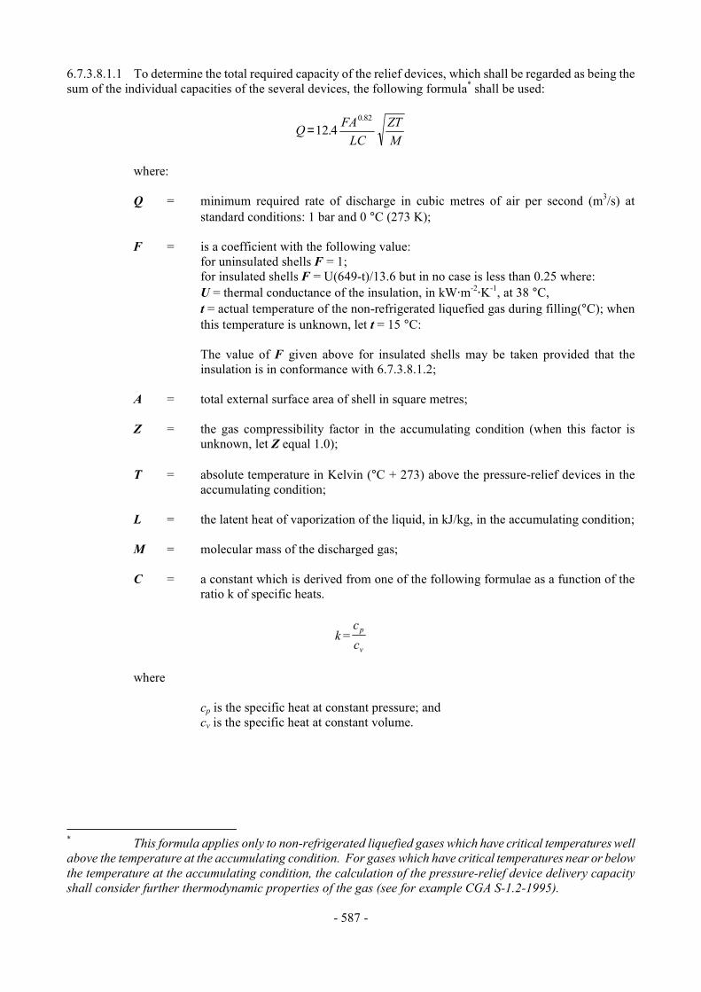
- 587 -
6.7.3.8.1.1 To determine the total required capacity of the relief devices, which shall be regarded as being the sum of the individual capacities of the several devices, the following formula* shall be used:
Q FALC
ZTM
=12 40.82
.
where: Q = minimum required rate of discharge in cubic metres of air per second (m3/s) at
standard conditions: 1 bar and 0 °C (273 K); F = is a coefficient with the following value: for uninsulated shells F = 1; for insulated shells F = U(649-t)/13.6 but in no case is less than 0.25 where: U = thermal conductance of the insulation, in kW@m-2
@K-1, at 38 °C, t = actual temperature of the non-refrigerated liquefied gas during filling(°C); when
this temperature is unknown, let t = 15 °C: The value of F given above for insulated shells may be taken provided that the
insulation is in conformance with 6.7.3.8.1.2; A = total external surface area of shell in square metres; Z = the gas compressibility factor in the accumulating condition (when this factor is
unknown, let Z equal 1.0); T = absolute temperature in Kelvin (°C + 273) above the pressure-relief devices in the
accumulating condition; L = the latent heat of vaporization of the liquid, in kJ/kg, in the accumulating condition; M = molecular mass of the discharged gas; C = a constant which is derived from one of the following formulae as a function of the
ratio k of specific heats.
kcc
p
v=
where cp is the specific heat at constant pressure; and cv is the specific heat at constant volume.
* This formula applies only to non-refrigerated liquefied gases which have critical temperatures well above the temperature at the accumulating condition. For gases which have critical temperatures near or below the temperature at the accumulating condition, the calculation of the pressure-relief device delivery capacity shall consider further thermodynamic properties of the gas (see for example CGA S-1.2-1995).

- 588 -
when k > 1:
C kk
kk
=+
+−2
1
11
when k = 1 or k is unknown
Ce
= =1 0 607.
where e is the mathematical constant 2.7183 C may also be taken from the following table:
k C
k C
k C
1.00 0.607 1.02 0.611 1.04 0.615 1.06 0.620 1.08 0.624 1.10 0.628 1.12 0.633 1.14 0.637 1.16 0.641 1.18 0.645 1.20 0.649 1.22 0.652 1.24 0.656
1.26 0.660 1.28 0.664 1.30 0.667 1.32 0.671 1.34 0.674 1.36 0.678 1.38 0.681 1.40 0.685 1.42 0.688 1.44 0.691 1.46 0.695 1.48 0.698 1.50 0.701
1.52 0.704 1.54 0.707 1.56 0.710 1.58 0.713 1.60 0.716 1.62 0.719 1.64 0.722 1.66 0.725 1.68 0.728 1.70 0.731 2.00 0.770 2.20 0.793
6.7.3.8.1.2 Insulation systems, used for the purpose of reducing the venting capacity, shall be approved by the competent authority or its authorized body. In all cases, insulation systems approved for this purpose shall: (a) Remain effective at all temperatures up to 649 °C; and (b) Be jacketed with a material having a melting point of 700 °C or greater. 6.7.3.9 Marking of pressure-relief devices 6.7.3.9.1 Every pressure-relief device shall be plainly and permanently marked with the following: (a) The pressure (in bar or kPa) at which it is set to discharge; (b) The allowable tolerance at the discharge pressure for spring-loaded devices; (c) The reference temperature corresponding to the rated pressure for frangible discs; and (d) The rated flow capacity of the device in standard cubic metres of air per second (m3/s).

- 589 -
When practicable, the following information shall also be shown: (e) The manufacturer=s name and relevant catalogue number. 6.7.3.9.2 The rated flow capacity marked on the pressure-relief devices shall be determined according to
ISO 4126-1:1991. 6.7.3.10 Connections to pressure-relief devices 6.7.3.10.1 Connections to pressure-relief devices shall be of sufficient size to enable the required discharge to pass unrestricted to the safety device. No stop-valve shall be installed between the shell and the pressure-relief devices except when duplicate devices are provided for maintenance or other reasons and the stop-valves serving the devices actually in use are locked open or the stop-valves are interlocked so that at least one of the duplicate devices is always operable and capable of meeting the requirements of 6.7.3.8. There shall be no obstruction in an opening leading to a vent or pressure-relief device which might restrict or cut-off the flow from the shell to that device. Vents from the pressure-relief devices, when used, shall deliver the relieved vapour or liquid to the atmosphere in conditions of minimum back-pressure on the relieving device. 6.7.3.11 Siting of pressure-relief devices 6.7.3.11.1 Each pressure-relief device inlet shall be situated on top of the shell in a position as near the longitudinal and transverse centre of the shell as reasonably practicable. All pressure relief device inlets shall under maximum filling conditions be situated in the vapour space of the shell and the devices shall be so arranged as to ensure that the escaping vapour is discharged unrestrictedly. For flammable non-refrigerated liquefied gases, the escaping vapour shall be directed away from the shell in such a manner that it cannot impinge upon the shell. Protective devices which deflect the flow of vapour are permissible provided the required relief-device capacity is not reduced. 6.7.3.11.2 Arrangements shall be made to prevent access to the pressure-relief devices by unauthorized persons and to protect the devices from damage caused by the portable tank overturning. 6.7.3.12 Gauging devices 6.7.3.12.1 Unless a portable tank is intended to be filled by weight it shall be equipped with one or more gauging devices. Glass level-gauges and gauges made of other fragile material, which are in direct communication with the contents of the shell shall not be used. 6.7.3.13 Portable tank supports, frameworks, lifting and tie-down attachments 6.7.3.13.1 Portable tanks shall be designed and constructed with a support structure to provide a secure base during transport. The forces specified in 6.7.3.2.9 and the safety factor specified in 6.7.3.2.10 shall be considered in this aspect of the design. Skids, frameworks, cradles or other similar structures are acceptable. 6.7.3.13.2 The combined stresses caused by portable tank mountings (e.g. cradles, frameworks, etc.) and portable tank lifting and tie-down attachments shall not cause excessive stress in any portion of the shell. Permanent lifting and tie-down attachments shall be fitted to all portable tanks. Preferably they shall be fitted to the portable tank supports but may be secured to reinforcing plates located on the shell at the points of support. 6.7.3.13.3 In the design of supports and frameworks the effects of environmental corrosion shall be taken into account.

- 590 -
6.7.3.13.4 Forklift pockets shall be capable of being closed off. The means of closing forklift pockets shall be a permanent part of the framework or permanently attached to the framework. Single compartment portable tanks with a length less than 3.65 m need not have closed off forklift pockets provided that:
(a) The shell and all the fittings are well protected from being hit by the forklift blades; and (b) The distance between the centres of the forklift pockets is at least half of the maximum
length of the portable tank. 6.7.3.13.5 When portable tanks are not protected during transport, according to 4.2.2.3, the shells and service equipment shall be protected against damage to the shell and service equipment resulting from lateral or longitudinal impact or overturning. External fittings shall be protected so as to preclude the release of the shell contents upon impact or overturning of the portable tank on its fittings. Examples of protection include: (a) Protection against lateral impact which may consist of longitudinal bars protecting the shell
on both sides at the level of the median line; (b) Protection of the portable tank against overturning which may consist of reinforcement rings
or bars fixed across the frame; (c) Protection against rear impact which may consist of a bumper or frame; (d) Protection of the shell against damage from impact or overturning by use of an ISO frame in
accordance with ISO 1496-3:1995. 6.7.3.14 Design approval 6.7.3.14.1 The competent authority or its authorized body shall issue a design approval certificate for any new design of a portable tank. This certificate shall attest that a portable tank has been surveyed by that authority, is suitable for its intended purpose and meets the requirements of this Chapter and where appropriate the provisions for gases provided in portable tank instruction T50 in 4.2.5.2.6. When a series of portable tanks are manufactured without change in the design, the certificate shall be valid for the entire series. The certificate shall refer to the prototype test report, the gases allowed to be transported, the materials of construction of the shell and an approval number. The approval number shall consist of the distinguishing sign or mark of the State in whose territory the approval was granted, i.e. the distinguishing sign for use in international traffic, as prescribed by the Convention on Road Traffic, Vienna 1968, and a registration number. Any alternative arrangements according to 6.7.1.2 shall be indicated on the certificate. A design approval may serve for the approval of smaller portable tanks made of materials of the same kind and thickness, by the same fabrication techniques and with identical supports, equivalent closures and other appurtenances. 6.7.3.14.2 The prototype test report for the design approval shall include at least the following: (a) The results of the applicable framework test specified in ISO 1496-3:1995; (b) The results of the initial inspection and test in 6.7.3.15.3; and (c) The results of the impact test in 6.7.3.15.1, when applicable.
- 591 -
6.7.3.15 Inspection and testing 6.7.3.15.1 For portable tanks meeting the definition of container in the CSC, a prototype representing each design shall be subjected to an impact test. The prototype portable tank shall be shown to be capable of absorbing the forces resulting from an impact not less than 4 times (4 g) the MPGM of the fully loaded portable tank at a duration typical of the mechanical shocks experienced in rail transport. The following is a listing of standards describing methods acceptable for performing the impact test: Association of American Railroads, Manual of Standards and Recommended Practices, Specifications for Acceptability of Tank Containers (AAR.600), 1992 Canadian Standards Association (CSA), Highway Tanks and Portable Tanks for the Transportation of Dangerous Goods (B620-1987) Deutsche Bahn AG Zentralbereich Technik, Minden Portable tanks, longitudinal dynamic impact test Société Nationale des Chemins de Fer Français C.N.E.S.T. 002-1966. Tank containers, longitudinal external stresses and dynamic impact tests
Spoornet, South Africa Engineering Development Centre (EDC) Testing of ISO Tank Containers Method EDC/TES/023/000/1991-06
6.7.3.15.2 The shell and items of equipment of each portable tank shall be inspected and tested before being put into service for the first time (initial inspection and test) and thereafter at not more than five-year intervals (5 year periodic inspection and test) with an intermediate periodic inspection and test (2.5 year periodic inspection and test) midway between the 5 year periodic inspections and tests. The 2.5 year inspection and test may be performed within 3 months of the specified date. An exceptional inspection and test shall be performed regardless of the last periodic inspection and test when necessary according to 6.7.3.15.7. 6.7.3.15.3 The initial inspection and test of a portable tank shall include a check of the design characteristics, an internal and external examination of the portable tank and its fittings with due regard to the non-refrigerated liquefied gases to be transported, and a pressure test referring to the test pressures according to 6.7.3.3.2. The pressure test may be performed as a hydraulic test or by using another liquid or gas with the agreement of the competent authority or its authorized body. Before the portable tank is placed into service, a leakproofness test and a test of the satisfactory operation of all service equipment shall also be performed. When the shell and its fittings have been pressure-tested separately, they shall be subjected together after assembly to a leakproofness test. All welds subject to full stress level in the shell shall be inspected during the initial test by radiographic, ultrasonic, or another suitable non-destructive test method. This does not apply to the jacket. 6.7.3.15.4 The 5 year periodic inspection and test shall include an internal and external examination and, as a general rule, a hydraulic pressure test. Sheathing, thermal insulation and the like shall be removed only to the extent required for reliable appraisal of the condition of the portable tank. When the shell and equipment have been pressure-tested separately, they shall be subjected together after assembly to a leakproofness test.
- 592 -
6.7.3.15.5 The intermediate 2.5 year periodic inspection and test shall at least include an internal and external examination of the portable tank and its fittings with due regard to the non-refrigerated liquefied gases intended to be transported, a leakproofness test and a test of the satisfactory operation of all service equipment. Sheathing thermal insulation and the like shall be removed only to the extent required for reliable appraisal of the condition of the portable tank. For portable tanks intended for the transport of a single non-refrigerated liquefied gas, the 2.5 year internal examination may be waived or substituted by other test methods or inspection procedures specified by the competent authority or its authorized body. 6.7.3.15.6 A portable tank may not be filled and offered for transport after the date of expiry of the last 5 year or 2.5 year periodic inspection and test as required by 6.7.3.15.2. However a portable tank filled prior to the date of expiry of the last periodic inspection and test may be transported for a period not to exceed three months beyond the date of expiry of the last periodic test or inspection. In addition, a portable tank may be transported after the date of expiry of the last periodic test and inspection:
(a) After emptying but before cleaning, for purposes of performing the next required test or inspection prior to refilling; and
(b) Unless otherwise approved by the competent authority, for a period not to exceed six months
beyond the date of expiry of the last periodic test or inspection, in order to allow the return of dangerous goods for proper disposal or recycling. Reference to this exemption shall be mentioned in the transport document.
6.7.3.15.7 The exceptional inspection and test is necessary when the portable tank shows evidence of damaged or corroded areas, or leakage, or other conditions that indicate a deficiency that could affect the integrity of the portable tank. The extent of the exceptional inspection and test shall depend on the amount of damage or deterioration of the portable tank. It shall include at least the 2.5 year inspection and test according to 6.7.3.15.5. 6.7.3.15.8 The internal and external examinations shall ensure that: (a) The shell is inspected for pitting, corrosion, or abrasions, dents, distortions, defects in welds
or any other conditions, including leakage, that might render the portable tank unsafe for transport;
(b) The piping, valves, and gaskets are inspected for corroded areas, defects, or any other
conditions, including leakage, that might render the portable tank unsafe for filling, discharge or transport;
(c) Devices for tightening manhole covers are operative and there is no leakage at manhole
covers or gaskets; (d) Missing or loose bolts or nuts on any flanged connection or blank flange are replaced or
tightened; (e) All emergency devices and valves are free from corrosion, distortion and any damage or
defect that could prevent their normal operation. Remote closure devices and self-closing stop-valves shall be operated to demonstrate proper operation;
(f) Required markings on the portable tank are legible and in accordance with the applicable
requirements; and (g) The framework, the supports and the arrangements for lifting the portable tank are in
satisfactory condition.
- 593 -
6.7.3.15.9 The inspections and tests in 6.7.3.15.1, 6.7.3.15.3, 6.7.3.15.4, 6.7.3.15.5 and 6.7.3.15.7 shall be performed or witnessed by an expert approved by the competent authority or its authorized body. When the pressure test is a part of the inspection and test, the test pressure shall be the one indicated on the data plate of the portable tank. While under pressure, the portable tank shall be inspected for any leaks in the shell, piping or equipment. 6.7.3.15.10 In all cases when cutting, burning or welding operations on the shell have been effected, that work shall be to the approval of the competent authority or its authorized body taking into account the pressure vessel code used for the construction of the shell. A pressure test to the original test pressure shall be performed after the work is completed. 6.7.3.15.11 When evidence of any unsafe condition is discovered, the portable tank shall not be returned to service until it has been corrected and the pressure test is repeated and passed. 6.7.3.16 Marking 6.7.3.16.1 Every portable tank shall be fitted with a corrosion resistant metal plate permanently attached to the portable tank in a conspicuous place readily accessible for inspection. When for reasons of portable tank arrangements, the plate cannot be permanently attached to the shell, the shell shall be marked with at least the information required by the pressure vessel code. As a minimum at least the following information shall be marked on the plate by stamping or by any other similar method. Country of manufacture U Approval Approval For Alternative Arrangements (see 6.7.1.2): N Country Number "AA" Manufacturer's name or mark Manufacturer's serial number Authorized body for the design approval Owner's registration number Year of manufacture Pressure vessel code to which the shell is designed Test pressure _________ bar/kPa gauge* MAWP_________ bar/kPa gauge* External design pressure** _________ bar/kPa gauge*
Design temperature range ________ °C to ________ °C
Design reference temperature ________ °C
Water capacity at 20°C _________ litres Initial pressure test date and witness identification Shell material(s) and material standard reference(s) Equivalent thickness in reference steel __________ mm Date and type of most recent periodic test(s) Month _______ Year ________ Test pressure _________ bar/kPa gauge* Stamp of expert who performed or witnessed the most recent test
* The unit used shall be marked. ** See 6.7.3.2.8.
- 594 -
6.7.3.16.2 The following information shall be marked either on the portable tank itself or on a metal plate firmly secured to the portable tank: Name of the operator Name of non-refrigerated liquefied gas(es) permitted for transport Maximum permissible load mass for each non-refrigerated liquefied gas permitted ________ kg Maximum permissible gross mass (MPGM) __________ kg Unladen (tare) mass _________ kg NOTE: For the identification of the non-refrigerated liquefied gases being transported, see also Part 5. 6.7.3.16.3 If a portable tank is designed and approved for handling in open seas, the words "OFFSHORE PORTABLE TANK" shall be marked on the identification plate. 6.7.4 Requirements for the design, construction, inspection and testing of portable tanks intended for the transport of refrigerated liquefied gases 6.7.4.1 Definitions For the purposes of this section: Holding time means the time that will elapse from the establishment of the initial filling condition until the pressure has risen due to heat influx to the lowest set pressure of the pressure limiting device(s); Jacket means the outer insulation cover or cladding which may be part of the insulation system; Leakproofness test means a test using gas subjecting the shell and its service equipment, to an effective internal pressure not less than 90% of the MAWP; Maximum allowable working pressure (MAWP) means the maximum effective gauge pressure permissible at the top of the shell of a loaded portable tank in its operating position including the highest effective pressure during filling and discharge; Maximum permissible gross mass (MPGM) means the sum of the tare mass of the portable tank and the heaviest load authorized for transport; Minimum design temperature means the temperature which is used for the design and construction of the shell not higher than the lowest (coldest) temperature (service temperature) of the contents during normal conditions of filling, discharge and transport; Portable tank means a thermally insulated multimodal tank having a capacity of more than 450 litres fitted with service equipment and structural equipment necessary for the transport of refrigerated liquefied gases. The portable tank shall be capable of being filled and discharged without the removal of its structural equipment. It shall possess stabilizing members external to the tank, and shall be capable of being lifted when full. It shall be designed primarily to be loaded onto a transport vehicle or ship and shall be equipped with skids, mountings or accessories to facilitate mechanical handling. Road tank-vehicles, rail tank-wagons, non-metallic tanks, intermediate bulk containers (IBCs), gas cylinders and large receptacles are not considered to fall within the definition for portable tanks; Reference steel means a steel with a tensile strength of 370 N/mm2 and an elongation at fracture of 27%;
- 595 -
Shell means the part of the portable tank which retains the refrigerated liquefied gas intended for transport, including openings and their closures, but does not include service equipment or external structural equipment; Service equipment means measuring instruments and filling, discharge, venting, safety, pressurizing, cooling and thermal insulation devices; Structural equipment means the reinforcing, fastening, protective and stabilizing members external to the shell; Tank means a construction which normally consists of either:
(a) A jacket and one or more inner shells where the space between the shell(s) and the jacket is exhausted of air (vacuum insulation) and may incorporate a thermal insulation system; or
(b) A jacket and an inner shell with an intermediate layer of solid thermally insulating material
(e.g. solid foam); Test pressure means the maximum gauge pressure at the top of the shell during the pressure test. 6.7.4.2 General design and construction requirements 6.7.4.2.1 Shells shall be designed and constructed in accordance with the requirements of a pressure vessel code recognized by the competent authority. Shells and jackets shall be made of metallic materials suitable for forming. Jackets shall be made of steel. Non-metallic materials may be used for the attachments and supports between the shell and jacket, provided their material properties at the minimum design temperature are proven to be sufficient. The materials shall in principle conform to national or international material standards. For welded shells and jackets only materials whose weldability has been fully demonstrated shall be used. Welds shall be skilfully made and afford complete safety. When the manufacturing process or the materials make it necessary, the shell shall be suitably heat treated to guarantee adequate toughness in the weld and in the heat affected zones. In choosing the material, the minimum design temperature shall be taken into account with respect to risk of brittle fracture, to hydrogen embrittlement, to stress corrosion cracking and to resistance to impact. When fine grain steel is used, the guaranteed value of the yield strength shall be not more than 460 N/mm2 and the guaranteed value of the upper limit of the tensile strength shall be not more than 725 N/mm2 in accordance with the material specifications. Portable tank materials shall be suitable for the external environment in which they may be transported. 6.7.4.2.2 Any part of a portable tank, including fittings, gaskets and pipe-work, which can be expected normally to come into contact with the refrigerated liquefied gas transported shall be compatible with that refrigerated liquefied gas. 6.7.4.2.3 Contact between dissimilar metals which could result in damage by galvanic action shall be avoided. 6.7.4.2.4 The thermal insulation system shall include a complete covering of the shell(s) with effective insulating materials. External insulation shall be protected by a jacket so as to prevent the ingress of moisture and other damage under normal transport conditions. 6.7.4.2.5 When a jacket is so closed as to be gas-tight, a device shall be provided to prevent any dangerous pressure from developing in the insulation space. 6.7.4.2.6 Portable tanks intended for the transport of refrigerated liquefied gases having a boiling point below minus 182 °C at atmospheric pressure shall not include materials which may react with oxygen or oxygen enriched atmospheres in a dangerous manner, when located in parts of the thermal insulation when there is a risk of contact with oxygen or with oxygen enriched fluid.

- 596 -
6.7.4.2.7 Insulating materials shall not deteriorate unduly in service. 6.7.4.2.8 A reference holding time shall be determined for each refrigerated liquefied gas intended for transport in a portable tank. 6.7.4.2.8.1 The reference holding time shall be determined by a method recognized by the competent authority on the basis of the following:
(a) The effectiveness of the insulation system, determined in accordance with 6.7.4.2.8.2;
(b) The lowest set pressure of the pressure limiting device(s);
(c) The initial filling conditions;
(d) An assumed ambient temperature of 30 °C;
(e) The physical properties of the individual refrigerated liquefied gas intended to be transported. 6.7.4.2.8.2 The effectiveness of the insulation system (heat influx in watts) shall be determined by type testing the portable tank in accordance with a procedure recognized by the competent authority. This test shall consist of either:
(a) A constant pressure test (for example at atmospheric pressure) when the loss of refrigerated liquefied gas is measured over a period of time; or
(b) A closed system test when the rise in pressure in the shell is measured over a period of time.
When performing the constant pressure test, variations in atmospheric pressure shall be taken into
account. When performing either tests corrections shall be made for any variation of the ambient temperature from the assumed ambient temperature reference value of 30 °C. NOTE: For the determination of the actual holding time before each journey, refer to 4.2.3.7. 6.7.4.2.9 The jacket of a vacuum-insulated double-wall tank shall have either an external design pressure not less than 100 kPa (1 bar) gauge pressure calculated in accordance with a recognized technical code or a calculated critical collapsing pressure of not less than 200 kPa (2 bar) gauge pressure. Internal and external reinforcements may be included in calculating the ability of the jacket to resist the external pressure. 6.7.4.2.10 Portable tanks shall be designed and constructed with supports to provide a secure base during transport and with suitable lifting and tie-down attachments. 6.7.4.2.11 Portable tanks shall be designed to withstand, without loss of contents, at least the internal pressure due to the contents, and the static, dynamic and thermal loads during normal conditions of handling and transport. The design shall demonstrate that the effects of fatigue, caused by repeated application of these loads through the expected life of the portable tank, have been taken into account.

- 597 -
6.7.4.2.12 Portable tanks and their fastenings under the maximum permissible load shall be capable of absorbing the following separately applied static forces:
(a) In the direction of travel: twice the MPGM multiplied by the acceleration due to gravity (g)*; (b) Horizontally at right angles to the direction of travel: the MPGM (when the direction of
travel is not clearly determined, the forces shall be equal to twice the MPGM) multiplied by the acceleration due to gravity (g)*;
(c) Vertically upwards: the MPGM multiplied by the acceleration due to gravity (g)*; and (d) Vertically downwards: twice the MPGM (total loading including the effect of gravity)
multiplied by the acceleration due to gravity (g)*. 6.7.4.2.13 Under each of the forces in 6.7.4.2.12, the safety factor to be observed shall be as follows:
(a) For materials having a clearly defined yield point, a safety factor of 1.5 in relation to the guaranteed yield strength; or
(b) For materials with no clearly defined yield point, a safety factor of 1.5 in relation to the
guaranteed 0.2% proof strength or, for austenitic steels, the 1% proof strength. 6.7.4.2.14 The values of yield strength or proof strength shall be the values according to national or international material standards. When austenitic steels are used, the specified minimum values according to the material standards may be increased by up to 15% when these greater values are attested in the material inspection certificate. When no material standard exists for the metal in question, or when non-metallic materials are used the values of yield strength or proof strength shall be approved by the competent authority. 6.7.4.2.15 Portable tanks intended for the transport of flammable refrigerated liquefied gases shall be capable of being electrically earthed. 6.7.4.3 Design criteria 6.7.4.3.1 Shells shall be of a circular cross section. 6.7.4.3.2 Shells shall be designed and constructed to withstand a test pressure not less than 1.3 times the MAWP. For shells with vacuum insulation the test pressure shall not be less than 1.3 times the sum of the MAWP and 100 kPa (1 bar). In no case shall the test pressure be less than 300 kPa (3 bar) gauge pressure. Attention is drawn to the minimum shell thickness requirements, specified in 6.7.4.4.2 to 6.7.4.4.7. 6.7.4.3.3 For metals exhibiting a clearly defined yield point or characterized by a guaranteed proof strength (0.2% proof strength, generally, or 1% proof strength for austenitic steels) the primary membrane stress σ (sigma) in the shell shall not exceed 0.75 Re or 0.50 Rm, whichever is lower, at the test pressure, where:
Re = yield strength in N/mm2, or 0.2% proof strength or, for austenitic steels, 1% proof strength;
Rm = minimum tensile strength in N/mm2.
* For calculation purposes g = 9.81 m/s2.
- 598 -
6.7.4.3.3.1 The values of Re and Rm to be used shall be the specified minimum values according to national or international material standards. When austenitic steels are used, the specified minimum values for Re and Rm according to the material standards may be increased by up to 15% when greater values are attested in the material inspection certificate. When no material standard exists for the metal in question, the values of Re and Rm used shall be approved by the competent authority or its authorized body. 6.7.4.3.3.2 Steels which have a Re/Rm ratio of more than 0.85 are not allowed for the construction of welded shells. The values of Re and Rm to be used in determining this ratio shall be the values specified in the material inspection certificate. 6.7.4.3.3.3 Steels used in the construction of shells shall have an elongation at fracture, in %, of not less than 10 000/Rm with an absolute minimum of 16% for fine grain steels and 20% for other steels. Aluminium and aluminium alloys used in the construction of shells shall have an elongation at fracture, in %, of not less than 10 000/6Rm with an absolute minimum of 12%. 6.7.4.3.3.4 For the purpose of determining actual values for materials, it shall be noted that for sheet metal, the axis of the tensile test specimen shall be at right angles (transversely) to the direction of rolling. The permanent elongation at fracture shall be measured on test specimens of rectangular cross sections in accordance with ISO 6892:1998 using a 50 mm gauge length. 6.7.4.4 Minimum shell thickness 6.7.4.4.1 The minimum shell thickness shall be the greater thickness based on:
(a) The minimum thickness determined in accordance with the requirements in 6.7.4.4.2 to 6.7.4.4.7; and
(b) The minimum thickness determined in accordance with the recognized pressure vessel code
including the requirements in 6.7.4.3. 6.7.4.4.2 Shells of not more than 1.80 m in diameter shall be not less than 5 mm thick in the reference steel or of equivalent thickness in the metal to be used. Shells of more than 1.80 m in diameter shall be not less than 6 mm thick in the reference steel or of equivalent thickness in the metal to be used. 6.7.4.4.3 Shells of vacuum-insulated tanks of not more than 1.80 m in diameter shall be not less than 3 mm thick in the reference steel or of equivalent thickness in the metal to be used. Such shells of more than 1.80 m in diameter shall be not less than 4 mm thick in the reference steel or of equivalent thickness in the metal to be used. 6.7.4.4.4 For vacuum-insulated tanks, the aggregate thickness of the jacket and the shell shall correspond to the minimum thickness prescribed in 6.7.4.4.2, the thickness of the shell itself being not less than the minimum thickness prescribed in 6.7.4.4.3. 6.7.4.4.5 Shells shall be not less than 3 mm thick regardless of the material of construction. 6.7.4.4.6 The equivalent thickness of a metal other than the thickness prescribed for the reference steel in 6.7.4.4.2 and 6.7.4.4.3 shall be determined using the following formula:
e x eRm x A1
0
1 13
214=
.
- 599 -
where: e1 = required equivalent thickness (in mm) of the metal to be used; e0 = minimum thickness (in mm) of the reference steel specified in 6.7.4.4.2 and 6.7.4.4.3; Rm1 = guaranteed minimum tensile strength (in N/mm2) of the metal to be used
(see 6.7.4.3.3); A1 = guaranteed minimum elongation at fracture (in %) of the metal to be used according to
national or international standards. 6.7.4.4.7 In no case shall the wall thickness be less than that prescribed in 6.7.4.4.1 to 6.7.4.4.5. All parts of the shell shall have a minimum thickness as determined by 6.7.4.4.1 to 6.7.4.4.6. This thickness shall be exclusive of any corrosion allowance. 6.7.4.4.8 There shall be no sudden change of plate thickness at the attachment of the ends (heads) to the cylindrical portion of the shell. 6.7.4.5 Service equipment 6.7.4.5.1 Service equipment shall be so arranged as to be protected against the risk of being wrenched off or damaged during handling and transport. When the connection between the frame and the tank or the jacket and the shell allows relative movement, the equipment shall be so fastened as to permit such movement without risk of damage to working parts. The external discharge fittings (pipe sockets, shut-off devices), the stop-valve and its seating shall be protected against the danger of being wrenched off by external forces (for example using shear sections). The filling and discharge devices (including flanges or threaded plugs) and any protective caps shall be capable of being secured against unintended opening. 6.7.4.5.2 Each filling and discharge opening in portable tanks used for the transport of flammable refrigerated liquefied gases shall be fitted with at least three mutually independent shut-off devices in series, the first being a stop-valve situated as close as reasonably practicable to the jacket, the second being a stop-valve and the third being a blank flange or equivalent device. The shut-off device closest to the jacket shall be a quick closing device, which closes automatically in the event of unintended movement of the portable tank during filling or discharge or fire engulfment. This device shall also be possible to operate by remote control. 6.7.4.5.3 Each filling and discharge opening in portable tanks used for the transport of non-flammable refrigerated liquefied gases shall be fitted with at least two mutually independent shut-off devices in series, the first being a stop-valve situated as close as reasonably practicable to the jacket, the second a blank flange or equivalent device. 6.7.4.5.4 For sections of piping which can be closed at both ends and where liquid product can be trapped, a method of automatic pressure relief shall be provided to prevent excess pressure build-up within the piping. 6.7.4.5.5 Vacuum insulated tanks need not have an opening for inspection. 6.7.4.5.6 External fittings shall be grouped together so far as reasonably practicable. 6.7.4.5.7 Each connection on a portable tank shall be clearly marked to indicate its function. 6.7.4.5.8 Each stop-valve or other means of closure shall be designed and constructed to a rated pressure not less than the MAWP of the shell taking into account the temperature expected during transport. All stop-valves with a screwed spindle shall be closed by a clockwise motion of the handwheel. In the case of other stop-valves the position (open and closed) and direction of closure shall be clearly indicated. All stop-valves shall be designed to prevent unintentional opening.
- 600 -
6.7.4.5.9 When pressure-building units are used, the liquid and vapour connections to that unit shall be provided with a valve as close to the jacket as reasonably practicable to prevent the loss of contents in case of damage to the pressure-building unit. 6.7.4.5.10 Piping shall be designed, constructed and installed so as to avoid the risk of damage due to thermal expansion and contraction, mechanical shock and vibration. All piping shall be of a suitable material. To prevent leakage due to fire, only steel piping and welded joints shall be used between the jacket and the connection to the first closure of any outlet. The method of attaching the closure to this connection shall be to the satisfaction of the competent authority or its authorized body. Elsewhere pipe joints shall be welded when necessary. 6.7.4.5.11 Joints in copper tubing shall be brazed or have an equally strong metal union. The melting point of brazing materials shall be no lower than 525 °C. The joints shall not decrease the strength of the tubing as may happen when cutting threads. 6.7.4.5.12 The materials of construction of valves and accessories shall have satisfactory properties at the lowest operating temperature of the portable tank. 6.7.4.5.13 The burst pressure of all piping and pipe fittings shall be not less than the highest of four times the MAWP of the shell or four times the pressure to which it may be subjected in service by the action of a pump or other device (except pressure-relief devices). 6.7.4.6 Pressure-relief devices 6.7.4.6.1 Every shell shall be provided with not less than two independent spring-loaded pressure-relief devices. The pressure-relief devices shall open automatically at a pressure not less than the MAWP and be fully open at a pressure equal to 110% of the MAWP. These devices shall, after discharge, close at a pressure not lower than 10% below the pressure at which discharge starts and shall remain closed at all lower pressures. The pressure-relief devices shall be of the type that will resist dynamic forces including surge. 6.7.4.6.2 Shells for non-flammable refrigerated liquefied gases and hydrogen may in addition have frangible discs in parallel with the spring-loaded devices as specified in 6.7.4.7.2 and 6.7.4.7.3. 6.7.4.6.3 Pressure-relief devices shall be designed to prevent the entry of foreign matter, the leakage of gas and the development of any dangerous excess pressure. 6.7.4.6.4 Pressure-relief devices shall be approved by the competent authority or its authorized body. 6.7.4.7 Capacity and setting of pressure-relief devices 6.7.4.7.1 In the case of the loss of vacuum in a vacuum-insulated tank or of loss of 20% of the insulation of a tank insulated with solid materials, the combined capacity of all pressure-relief devices installed shall be sufficient so that the pressure (including accumulation) inside the shell does not exceed 120% of the MAWP. 6.7.4.7.2 For non-flammable refrigerated liquefied gases (except oxygen) and hydrogen, this capacity may be achieved by the use of frangible discs in parallel with the required safety-relief devices. Frangible discs shall rupture at nominal pressure equal to the test pressure of the shell.
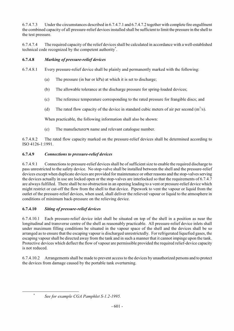
- 601 -
6.7.4.7.3 Under the circumstances described in 6.7.4.7.1 and 6.7.4.7.2 together with complete fire engulfment the combined capacity of all pressure-relief devices installed shall be sufficient to limit the pressure in the shell to the test pressure. 6.7.4.7.4 The required capacity of the relief devices shall be calculated in accordance with a well-established technical code recognized by the competent authority*. 6.7.4.8 Marking of pressure-relief devices 6.7.4.8.1 Every pressure-relief device shall be plainly and permanently marked with the following:
(a) The pressure (in bar or kPa) at which it is set to discharge;
(b) The allowable tolerance at the discharge pressure for spring-loaded devices; (c) The reference temperature corresponding to the rated pressure for frangible discs; and
(d) The rated flow capacity of the device in standard cubic meters of air per second (m3/s).
When practicable, the following information shall also be shown:
(e) The manufacturer=s name and relevant catalogue number.
6.7.4.8.2 The rated flow capacity marked on the pressure-relief devices shall be determined according to ISO 4126-1:1991. 6.7.4.9 Connections to pressure-relief devices 6.7.4.9.1 Connections to pressure-relief devices shall be of sufficient size to enable the required discharge to pass unrestricted to the safety device. No stop-valve shall be installed between the shell and the pressure-relief devices except when duplicate devices are provided for maintenance or other reasons and the stop-valves serving the devices actually in use are locked open or the stop-valves are interlocked so that the requirements of 6.7.4.7 are always fulfilled. There shall be no obstruction in an opening leading to a vent or pressure-relief device which might restrict or cut-off the flow from the shell to that device. Pipework to vent the vapour or liquid from the outlet of the pressure-relief devices, when used, shall deliver the relieved vapour or liquid to the atmosphere in conditions of minimum back-pressure on the relieving device. 6.7.4.10 Siting of pressure-relief devices 6.7.4.10.1 Each pressure-relief device inlet shall be situated on top of the shell in a position as near the longitudinal and transverse centre of the shell as reasonably practicable. All pressure-relief device inlets shall under maximum filling conditions be situated in the vapour space of the shell and the devices shall be so arranged as to ensure that the escaping vapour is discharged unrestrictedly. For refrigerated liquefied gases, the escaping vapour shall be directed away from the tank and in such a manner that it cannot impinge upon the tank. Protective devices which deflect the flow of vapour are permissible provided the required relief-device capacity is not reduced. 6.7.4.10.2 Arrangements shall be made to prevent access to the devices by unauthorized persons and to protect the devices from damage caused by the portable tank overturning.
* See for example CGA Pamphlet S-1.2-1995.
- 602 -
6.7.4.11 Gauging devices 6.7.4.11.1 Unless a portable tank is intended to be filled by weight, it shall be equipped with one or more gauging devices. Glass level-gauges and gauges made of other fragile material, which are in direct communication with the contents of the shell shall not be used. 6.7.4.11.2 A connection for a vacuum gauge shall be provided in the jacket of a vacuum-insulated portable tank. 6.7.4.12 Portable tank supports, frameworks, lifting and tie-down attachments 6.7.4.12.1 Portable tanks shall be designed and constructed with a support structure to provide a secure base during transport. The forces specified in 6.7.4.2.12 and the safety factor specified in 6.7.4.2.13 shall be considered in this aspect of the design. Skids, frameworks, cradles or other similar structures are acceptable. 6.7.4.12.2 The combined stresses caused by portable tank mountings (e.g. cradles, frameworks, etc.) and portable tank lifting and tie-down attachments shall not cause excessive stress in any portion of the tank. Permanent lifting and tie-down attachments shall be fitted to all portable tanks. Preferably they shall be fitted to the portable tank supports but may be secured to reinforcing plates located on the tank at the points of support. 6.7.4.12.3 In the design of supports and frameworks the effects of environmental corrosion shall be taken into account. 6.7.4.12.4 Forklift pockets shall be capable of being closed off. The means of closing forklift pockets shall be a permanent part of the framework or permanently attached to the framework. Single compartment portable tanks with a length less than 3.65 m need not have closed off forklift pockets provided that:
(a) The tank and all the fittings are well protected from being hit by the forklift blades; and
(b) The distance between the centres of the forklift pockets is at least half of the maximum
length of the portable tank. 6.7.4.12.5 When portable tanks are not protected during transport, according to 4.2.3.3, the shells and service equipment shall be protected against damage to the shell and service equipment resulting from lateral or longitudinal impact or overturning. External fittings shall be protected so as to preclude the release of the shell contents upon impact or overturning of the portable tank on its fittings. Examples of protection include: (a) Protection against lateral impact which may consist of longitudinal bars protecting the shell
on both sides at the level of the median line; (b) Protection of the portable tank against overturning which may consist of reinforcement rings
or bars fixed across the frame; (c) Protection against rear impact which may consist of a bumper or frame; (d) Protection of the shell against damage from impact or overturning by use of an ISO frame in
accordance with ISO 1496-3:1995; (e) Protection of the portable tank from impact or overturning by a vacuum insulation jacket.
- 603 -
6.7.4.13 Design approval 6.7.4.13.1 The competent authority or its authorized body shall issue a design approval certificate for any new design of a portable tank. This certificate shall attest that a portable tank has been surveyed by that authority, is suitable for its intended purpose and meets the requirements of this Chapter. When a series of portable tanks is manufactured without change in the design, the certificate shall be valid for the entire series. The certificate shall refer to the prototype test report, the refrigerated liquefied gases allowed to be transported, the materials of construction of the shell and jacket and an approval number. The approval number shall consist of the distinguishing sign or mark of the State in whose territory the approval was granted, i.e. the distinguishing sign for use in international traffic, as prescribed by the Convention on Road Traffic, Vienna 1968, and a registration number. Any alternative arrangements according to 6.7.1.2 shall be indicated on the certificate. A design approval may serve for the approval of smaller portable tanks made of materials of the same kind and thickness, by the same fabrication techniques and with identical supports, equivalent closures and other appurtenances. 6.7.4.13.2 The prototype test report for the design approval shall include at least the following:
(a) The results of the applicable frame-work test specified in ISO 1496-3:1995;
(b) The results of the initial inspection and test in 6.7.4.14.3; and
(c) The results of the impact test in 6.7.4.14.1, when applicable. 6.7.4.14 Inspection and testing 6.7.4.14.1 For portable tanks meeting the definition of container in the CSC, a prototype representing each design shall be subjected to an impact test. The prototype portable tank shall be shown to be capable of absorbing the forces resulting from an impact not less than 4 times (4 g) the MPGM of the fully loaded portable tank at a duration typical of the mechanical shocks experienced in rail transport. The following is a listing of standards describing methods acceptable for performing the impact test: Association of American Railroads, Manual of Standards and Recommended Practices, Specifications for Acceptability of Tank Containers (AAR.600), 1992 Canadian Standards Association (CSA), Highway Tanks and Portable Tanks for the Transportation of Dangerous Goods (B620-1987) Deutsche Bahn AG Zentralbereich Technik, Minden Portable tanks, longitudinal dynamic impact test Société Nationale des Chemins de Fer Français C.N.E.S.T. 002-1966. Tank containers, longitudinal external stresses and dynamic impact tests Spoornet, South Africa Engineering Development Centre (EDC) Testing of ISO Tank Containers Method EDC/EST/023/000/1991-06

- 604 -
6.7.4.14.2 The tank and items of equipment of each portable tank shall be inspected and tested before being put into service for the first time (initial inspection and test) and thereafter at not more than five-year intervals (5 year periodic inspection and test) with an intermediate periodic inspection and test (2.5 year periodic inspection and test) midway between the 5 year periodic inspections and tests. The 2.5 year inspection and test may be performed within 3 months of the specified date. An exceptional inspection and test shall be performed regardless of the last periodic inspection and test when necessary according to 6.7.4.14.7. 6.7.4.14.3 The initial inspection and test of a portable tank shall include a check of the design characteristics, an internal and external examination of the portable tank shell and its fittings with due regard to the refrigerated liquefied gases to be transported, and a pressure test referring to the test pressures according to 6.7.4.3.2. The pressure test may be performed as a hydraulic test or by using another liquid or gas with the agreement of the competent authority or its authorized body. Before the portable tank is placed into service, a leakproofness test and a test of the satisfactory operation of all service equipment shall also be performed. When the shell and its fittings have been pressure-tested separately, they shall be subjected together after assembly to a leakproofness test. All welds subject to full stress level shall be inspected during the initial test by radiographic, ultrasonic, or another suitable non-destructive test method. This does not apply to the jacket. 6.7.4.14.4 The 5 and 2.5 year periodic inspection and test shall include an external examination of the portable tank and its fittings with due regard to the refrigerated liquefied gases transported, a leakproofness test, a test of the satisfactory operation of all service equipment and a vacuum reading, when applicable. In the case of non-vacuum insulated tanks, the jacket and insulation shall be removed during a 2.5 year and a 5 year periodic inspection but only to the extent necessary for a reliable appraisal. 6.7.4.14.5 In addition, at the 5 year periodic inspection and test of non-vacuum insulated tanks the jacket and insulation shall be removed, but only to the extent necessary for a reliable appraisal. 6.7.4.14.6 A portable tank may not be filled and offered for transport after the date of expiry of the last 5 year or 2.5 year periodic inspection and test as required by 6.7.4.14.2. However a portable tank filled prior to the date of expiry of the last periodic inspection and test may be transported for a period not to exceed three months beyond the date of expiry of the last periodic test or inspection. In addition, a portable tank may be transported after the date of expiry of the last periodic test and inspection:
(a) After emptying but before cleaning, for purposes of performing the next required test or inspection prior to refilling; and
(b) Unless otherwise approved by the competent authority, for a period not to exceed six months
beyond the date of expiry of the last periodic test or inspection, in order to allow the return of dangerous goods for proper disposal or recycling. Reference to this exemption shall be mentioned in the transport document.
6.7.4.14.7 The exceptional inspection and test is necessary when the portable tank shows evidence of damaged or corroded areas, leakage, or any other conditions that indicate a deficiency that could affect the integrity of the portable tank. The extent of the exceptional inspection and test shall depend on the amount of damage or deterioration of the portable tank. It shall include at least the 2.5 year inspection and test according to 6.7.4.14.4. 6.7.4.14.8 The internal examination during the initial inspection and test shall ensure that the shell is inspected for pitting, corrosion, or abrasions, dents, distortions, defects in welds or any other conditions, that might render the portable tank unsafe for transport.
- 605 -
6.7.4.14.9 The external examination shall ensure that:
(a) The external piping, valves, pressurizing/cooling systems when applicable and gaskets are inspected for corroded areas, defects, or any other conditions, including leakage, that might render the portable tank unsafe for filling, discharge or transport;
(b) There is no leakage at any manhole covers or gaskets; (c) Missing or loose bolts or nuts on any flanged connection or blank flange are replaced or
tightened; (d) All emergency devices and valves are free from corrosion, distortion and any damage or
defect that could prevent their normal operation. Remote closure devices and self-closing stop-valves shall be operated to demonstrate proper operation;
(e) Required markings on the portable tank are legible and in accordance with the applicable
requirements; and (f) The framework, the supports and the arrangements for lifting the portable tank are in
satisfactory condition. 6.7.4.14.10 The inspections and tests in 6.7.4.14.1, 6.7.4.14.3, 6.7.4.14.4, 6.7.4.14.5 and 6.7.4.14.7 shall be performed or witnessed by an expert approved by the competent authority or its authorized body. When the pressure test is a part of the inspection and test, the test pressure shall be the one indicated on the data plate of the portable tank. While under pressure, the portable tank shall be inspected for any leaks in the shell, piping or equipment. 6.7.4.14.11 In all cases when cutting, burning or welding operations on the shell of a portable tank have been effected, that work shall be to the approval of the competent authority or its authorized body taking into account the pressure vessel code used for the construction of the shell. A pressure test to the original test pressure shall be performed after the work is completed. 6.7.4.14.12 When evidence of any unsafe condition is discovered, the portable tank shall not be returned to service until it has been corrected and the test is repeated and passed. 6.7.4.15 Marking 6.7.4.15.1 Every portable tank shall be fitted with a corrosion resistant metal plate permanently attached to the portable tank in a conspicuous place readily accessible for inspection. When for reasons of portable tank arrangements, the plate cannot be permanently attached to the shell, the shell shall be marked with at least the information required by the pressure vessel code. As a minimum at least the following information shall be marked on the plate by stamping or by any other similar method: Country of manufacture U Approval Approval For Alternative Arrangements (see 6.7.1.2): N Country Number AAA@ Manufacturer's name or mark Manufacturer's serial number Authorized body for the design approval Owner=s registration number Year of manufacture
- 606 -
Pressure vessel code to which the tank is designed Test pressure _________ bar/kPa gauge* MAWP _________ bar/kPa gauge* Minimum design temperature ________ °C Water capacity at 20 °C _________ litres Initial pressure test date and witness identification Shell material(s) and material standard reference(s) Equivalent thickness in reference steel __________ mm Date and type of most recent periodic test(s) Month _______ Year _______ Test pressure ________ bar/kPa gauge* Stamp of expert who performed or witnessed the most recent test _________ The name, in full, of the gas(es) for whose transport the portable tank is approved Either "thermally insulated" or "vacuum insulated" __________ effectiveness of the insulation system (heat influx) _________ Watts (W) Reference holding time ___________________ days or hours and initial Pressure ______________ bar/kPa gauge* and degree of filling _______ in kg for each refrigerated liquefied gas permitted for transport. 6.7.4.15.2 The following information shall be durably marked either on the portable tank itself or on a metal plate firmly secured to the portable tank. Name of the owner and the operator Name of the refrigerated liquefied gas being transported (and minimum mean bulk temperature) Maximum permissible gross mass (MPGM) ________ kg Unladen (tare) mass ________ kg Actual holding time for gas being transported ______ days (or hours) NOTE: For the identification of the refrigerated liquefied gas(es) being transported, see also Part 5. 6.7.4.15.3 If a portable tank is designed and approved for handling in open seas, the words "OFFSHORE PORTABLE TANK" shall be marked on the identification plate.
* The unit used shall be marked.

- 607 -
6.7.5 Requirements for the design, construction, inspection and testing of multiple-element gas containers (MEGCs) intended for the transport of non-refrigerated gases 6.7.5.1 Definitions For the purposes of this section: Elements are restricted to cylinders, tubes or bundles of cylinders; Leakproofness test means a test using gas subjecting the elements and the service equipment of the MEGC to an effective internal pressure of not less than 20% of the test pressure; Manifold means an assembly of piping and valves connecting the filling and/or discharge openings of the elements; Maximum permissible gross mass (MPGM) means the sum of the tare mass of the MEGC and the heaviest load authorized for transport; Service equipment means measuring instruments and filling, discharge, venting and safety devices; Structural equipment means the reinforcing, fastening, protective and stabilizing members external to the elements. 6.7.5.2 General design and construction requirements 6.7.5.2.1 The MEGC shall be capable of being loaded and discharged without the removal of its structural equipment. It shall possess stabilizing members external to the elements to provide structural integrity for handling and transport. MEGCs shall be designed and constructed with supports to provide a secure base during transport and with lifting and tie-down attachments which are adequate for lifting the MEGC including when loaded to its maximum permissible gross mass. The MEGC shall be designed to be loaded onto a transport unit or ship and shall be equipped with skids, mountings or accessories to facilitate mechanical handling. 6.7.5.2.2 MEGCs shall be designed, manufactured and equipped in such a way as to withstand all conditions to which they will be subjected during normal conditions of handling and transport. The design shall take into account the effects of dynamic loading and fatigue. 6.7.5.2.3 Elements of an MEGC shall be made of seamless steel and be constructed and tested according to Chapter 6.2. All of the elements in an MEGC shall be of the same design type. 6.7.5.2.4 Elements of MEGCs, fittings and pipework shall be: (a) compatible with the substances intended to be transported (for gases see ISO 11114-1:1997
and ISO 11114-2:2000); or (b) properly passivated or neutralized by chemical reaction. 6.7.5.2.5 Contact between dissimilar metals which could result in damage by galvanic action shall be avoided. 6.7.5.2.6 The materials of the MEGC, including any devices, gaskets, and accessories, shall not adversely affect the gases intended for transport in the MEGC.

- 608 -
6.7.5.2.7 MEGCs shall be designed to withstand, without loss of contents, at least the internal pressure due to the contents, and the static, dynamic and thermal loads during normal conditions of handling and transport. The design shall demonstrate that the effects of fatigue, caused by repeated application of these loads through the expected life of the multiple-element gas container, have been taken into account. 6.7.5.2.8 MEGCs and their fastenings shall, under the maximum permissible load, be capable of withstanding the following separately applied static forces: (a) in the direction of travel: twice the MPGM multiplied by the acceleration due to gravity (g)*; (b) horizontally at right angles to the direction of travel: the MPGM (when the direction of travel
is not clearly determined, the forces shall be equal to twice the MPGM) multiplied by the acceleration due to gravity (g)*;
(c) vertically upwards: the MPGM multiplied by the acceleration due to gravity (g)*; and (d) vertically downwards: twice the MPGM (total loading including the effect of gravity)
multiplied by the acceleration due to gravity (g)*. 6.7.5.2.9 Under the forces defined above, the stress at the most severely stressed point of the elements shall not exceed the values given in either the relevant standards of 6.2.2.1 or, if the elements are not designed, constructed and tested according to those standards, in the technical code or standard recognised or approved by the competent authority of the country of use (see 6.2.3.1). 6.7.5.2.10 Under each of the forces in 6.7.5.2.8, the safety factor for the framework and fastenings to be observed shall be as follows: (a) for steels having a clearly defined yield point, a safety factor of 1.5 in relation to the
guaranteed yield strength; or (b) for steels with no clearly defined yield point, a safety factor of 1.5 in relation to the
guaranteed 0.2% proof strength and, for austenitic steels, the 1% proof strength. 6.7.5.2.11 MEGCs intended for the transport of flammable gases shall be capable of being electrically earthed. 6.7.5.2.12 The elements shall be secured in a manner that prevents undesired movement in relation to the structure and the concentration of harmful localized stresses. 6.7.5.3 Service equipment 6.7.5.3.1 Service equipment shall be configured or designed to prevent damage that could result in the release of the pressure receptacle contents during normal conditions of handling and transport. When the connection between the frame and the elements allows relative movement between the sub-assemblies, the equipment shall be so fastened as to permit such movement without damage to working parts. The manifolds, the discharge fittings (pipe sockets, shut-off devices), and the stop-valves shall be protected from being wrenched off by external forces. Manifold piping leading to shut-off valves shall be sufficiently flexible to protect the valves and the piping from shearing, or releasing the pressure receptacle contents. The filling and discharge devices (including flanges or threaded plugs) and any protective caps shall be capable of being secured against unintended opening.
* For calculation purposes g = 9.81 m/s2.
- 609 -
6.7.5.3.2 Each element intended for the transport of gases of Division 2.3 shall be fitted with a valve. The manifold for liquefied gases of Division 2.3 shall be so designed that the elements can be filled separately and be kept isolated by a valve capable of being sealed. For the transport of gases of Division 2.1, the elements shall be isolated by a valve into assemblies of not more than 3000 litres. 6.7.5.3.3 For filling and discharge openings of the MEGC, two valves in series shall be placed in an accessible position on each discharge and filling pipe. One of the valves may be a non-return valve. The filling and discharge devices may be fitted to a manifold. For sections of piping which can be closed at both ends and where a liquid product can be trapped, a pressure-relief valve shall be provided to prevent excessive pressure build-up. The main isolation valves on an MEGC shall be clearly marked to indicate their directions of closure. Each stop-valve or other means of closure shall be designed and constructed to withstand a pressure equal to or greater than 1.5 times the test pressure of the MEGC. All stop-valves with screwed spindles shall close by a clockwise motion of the handwheel. For other stop-valves, the position (open or closed) and direction of closure shall be clearly indicated. All stop-valves shall be designed and positioned to prevent unintentional opening. Ductile metals shall be used in the construction of valves or accessories. 6.7.5.3.4 Piping shall be designed, constructed and installed so as to avoid damage due to expansion and contraction, mechanical shock and vibration. Joints in tubing shall be brazed or have an equally strong metal union. The melting point of brazing materials shall be no lower than 525 °C. The rated pressure of the service equipment and of the manifold shall be not less than two thirds of the test pressure of the elements. 6.7.5.4 Pressure-relief devices 6.7.5.4.1 One or more pressure relief devices shall be fitted on MEGCs used for the transport of UN 1013 carbon dioxide and UN 1070 nitrous oxide. Other MEGCs shall be fitted with pressure relief devices as specified by the competent authority for the country use. 6.7.5.4.2 When pressure relief devices are fitted, every element or group of elements of an MEGC that can be isolated shall then be fitted with one or more pressure relief devices. Pressure relief devices shall be of a type that will resist dynamic forces including liquid surge and shall be designed to prevent the entry of foreign matter, the leakage of gas and the development of any dangerous excess pressure. 6.7.5.4.3 MEGCs used for the transport of certain non-refrigerated gases identified in instruction T50 in 4.2.5.2.6 may have a pressure-relief device as required by the competent authority of the country of use. Unless an MEGC in dedicated service is fitted with an approved pressure relief device constructed of materials compatible with the load, such a device shall comprise a frangible disc preceding a spring-loaded device. The space between the frangible disc and the spring-loaded device may be equipped with a pressure gauge or a suitable telltale indicator. This arrangement permits the detection of disc rupture, pinholing or leakage which could cause a malfunction of the pressure relief device. The frangible disc shall rupture at a nominal pressure 10% above the start-to-discharge pressure of the spring-loaded device. 6.7.5.4.4 In the case of multi-purpose MEGCs used for the transport of low-pressure liquefied gases, the pressure-relief devices shall open at a pressure as specified in 6.7.3.7.1 for the gas having the highest maximum allowable working pressure of the gases allowed to be transported in the MEGC. 6.7.5.5 Capacity of pressure relief devices 6.7.5.5.1 The combined delivery capacity of the pressure relief devices when fitted shall be sufficient that, in the event of total fire engulfment, the pressure (including accumulation) inside the elements does not exceed 120% of the set pressure of the pressure relief device. The formula provided in CGA S-1.2-1995 shall be used to determine the minimum total flow capacity for the system of pressure relief devices.CGA S-1.1-1994 may be used to determine the relief capacity of individual elements. Spring-loaded pressure relief devices may be used to achieve the full relief capacity prescribed in the case of low pressure liquefied gases. In the case of multi-purpose MEGCs, the combined delivery capacity of the pressure-relief devices shall be taken for the gas which requires the highest delivery capacity of the gases allowed to be transported in the MEGC.
- 610 -
6.7.5.5.2 To determine the total required capacity of the pressure relief devices installed on the elements for the transport of liquefied gases, the thermodynamic properties of the gas shall be considered (see, for example, CGA S-1.2-1995 for low pressure liquefied gases and CGA S-1.1-1994 for high pressure liquefied gases). 6.7.5.6 Marking of pressure-relief devices 6.7.5.6.1 Spring loaded pressure relief devices shall be clearly and permanently marked with the following: (a) the pressure (in bar or kPa) at which it is set to discharge; (b) the allowable tolerance at the discharge pressure; (c) the rated flow capacity of the device in standard cubic metres of air per second (m3/s); When practicable, the following information shall also be shown: (d) the manufacturer's name and relevant catalogue number. 6.7.5.6.2 The rated flow capacity marked on frangible discs shall be determined according to CGA S-1.1-1994. 6.7.5.6.3 The rated flow capacity marked on spring loaded pressure relief devices for low pressure liquefied gases shall be determined according to ISO 4126-1:1991. 6.7.5.7 Connections to pressure-relief devices 6.7.5.7.1 Connections to pressure-relief devices shall be of sufficient size to enable the required discharge to pass unrestricted to the pressure relief device. No stop-valve shall be installed between the element and the pressure-relief devices, except when duplicate devices are provided for maintenance or other reasons, and the stop-valves serving the devices actually in use are locked open, or the stop-valves are interlocked so that at least one of the duplicate devices is always operable and capable of meeting the requirements of 6.7.5.5. There shall be no obstruction in an opening leading to or leaving from a vent or pressure-relief device which might restrict or cut-off the flow from the element to that device. The opening through all piping and fittings shall have at least the same flow area as the inlet of the pressure relief device to which it is connected. The nominal size of the discharge piping shall be at least as large as that of the pressure relief device outlet. Vents from the pressure-relief devices, when used, shall deliver the relieved vapour or liquid to the atmosphere in conditions of minimum backpressure on the relieving device. 6.7.5.8 Siting of pressure-relief devices 6.7.5.8.1 Each pressure relief device shall, under maximum filling conditions, be in communication with the vapour space of the elements for the transport of liquefied gases. The devices, when fitted, shall be so arranged as to ensure that the escaping vapour is discharged upwards and unrestrictedly as to prevent any impingement of escaping gas or liquid upon the MEGC, its elements or personnel. For flammable and oxidising gases, the escaping gas shall be directed away from the element in such a manner that it cannot impinge upon the other elements. Heat resistant protective devices which deflect the flow of gas are permissible provided the required pressure relief device capacity is not reduced. 6.7.5.8.2 Arrangements shall be made to prevent access to the pressure-relief devices by unauthorized persons and to protect the devices from damage caused by the MEGC overturning.
- 611 -
6.7.5.9 Gauging devices 6.7.5.9.1 When a MEGC is intended to be filled by mass, it shall be equipped with one or more gauging devices. Level-gauges made of glass or other fragile material shall not be used. 6.7.5.10 MEGC supports, frameworks, lifting and tie-down attachments 6.7.5.10.1 MEGCs shall be designed and constructed with a support structure to provide a secure base during transport. The forces specified in 6.7.5.2.8 and the safety factor specified in 6.7.5.2.10 shall be considered in this aspect of the design. Skids, frameworks, cradles or other similar structures are acceptable. 6.7.5.10.2 The combined stresses caused by element mountings (e.g. cradles, frameworks, etc.) and MEGC lifting and tie-down attachments shall not cause excessive stress in any element. Permanent lifting and tie-down attachments shall be fitted to all MEGCs. In no case shall mountings or attachments be welded onto the elements. 6.7.5.10.3 In the design of supports and frameworks, the effects of environmental corrosion shall be taken into account. 6.7.5.10.4 When MEGCs are not protected during transport, according to 4.2.5.3, the elements and service equipment shall be protected against damage resulting from lateral or longitudinal impact or overturning. External fittings shall be protected so as to preclude the release of the elements' contents upon impact or overturning of the MEGC on its fittings. Particular attention shall be paid to the protection of the manifold. Examples of protection include: (a) protection against lateral impact which may consist of longitudinal bars; (b) protection against overturning which may consist of reinforcement rings or bars fixed across
the frame; (c) protection against rear impact which may consist of a bumper or frame; (d) protection of the elements and service equipment against damage from impact or overturning
by use of an ISO frame in accordance with the relevant provisions of ISO 1496-3:1995. 6.7.5.11 Design approval 6.7.5.11.1 The competent authority or its authorized body shall issue a design approval certificate for any new design of a MEGC. This certificate shall attest that the MEGC has been surveyed by that authority, is suitable for its intended purpose and meets the requirements of this Chapter, the applicable provisions for gases of Chapter 4.1 and of packing instruction P200. When a series of MEGCs are manufactured without change in the design, the certificate shall be valid for the entire series. The certificate shall refer to the prototype test report, the materials of construction of the manifold, the standards to which the elements are made and an approval number. The approval number shall consist of the distinguishing sign or mark of the country granting the approval, i.e. the distinguishing sign for use in international traffic, as prescribed by the Convention on Road Traffic, Vienna 1968, and a registration number. Any alternative arrangements according to 6.7.1.2 shall be indicated on the certificate. A design approval may serve for the approval of smaller MEGCs made of materials of the same type and thickness, by the same fabrication techniques and with identical supports, equivalent closures and other appurtenances.
- 612 -
6.7.5.11.2 The prototype test report for the design approval shall include at least the following: (a) the results of the applicable framework test specified in ISO 1496-3:1995; (b) the results of the initial inspection and test specified in 6.7.5.12.3; (c) the results of the impact test specified in 6.7.5.12.1; and (d) certification documents verifying that the cylinders and tubes comply with the applicable
standards. 6.7.5.12 Inspection and testing 6.7.5.12.1 For MEGCs meeting the definition of container in the CSC, a prototype representing each design shall be subjected to an impact test. The prototype MEGC shall be shown to be capable of absorbing the forces resulting from an impact not less than 4 times (4 g) the MPGM of the fully loaded MEGC at a duration typical of the mechanical shocks experienced in rail transport. The following is a listing of standards describing methods acceptable for performing the impact test: Association of American Railroads, Manual of Standards and Recommended Practices, Specifications for Acceptability of Tank Containers (AAR.600), 1992 Canadian Standards Association (CSA), Highway Tanks and Portable Tanks for the Transportation of Dangerous Goods (B620-1987) Deutsche Bahn AG Zentralbereich Technik, Minden Transportable tanks, longitudinal dynamic impact test Société Nationale des Chemins de Fer Français C.N.E.S.T. 002-1966. Tank containers, longitudinal external stresses and dynamic impact tests Spoornet, South Africa Engineering Development Centre (EDC) Testing of ISO Tank Containers Method EDC/TES/023/000/1991-06 6.7.5.12.2 The elements and items of equipment of each MEGC shall be inspected and tested before being put into service for the first time (initial inspection and test). Thereafter, MEGCs shall be inspected at no more than five-year intervals (5 year periodic inspection). An exceptional inspection and test shall be performed, regardless of the last periodic inspection and test, when necessary according to 6.7.5.12.5. 6.7.5.12.3 The initial inspection and test of an MEGC shall include a check of the design characteristics, an external examination of the MEGC and its fittings with due regard to the gases to be transported, and a pressure test performed at the test pressures according to packing instruction P200. The pressure test of the manifold may be performed as a hydraulic test or by using another liquid or gas with the agreement of the competent authority or its authorized body. Before the MEGC is placed into service, a leakproofness test and a test of the satisfactory operation of all service equipment shall also be performed. When the elements and their fittings have been pressure-tested separately, they shall be subjected together after assembly to a leakproofness test.
- 613 -
6.7.5.12.4 The 5-year periodic inspection shall include an external examination of the structure, the elements and the service equipment in accordance with 6.7.5.12.6. The elements and the piping shall be tested at the periodicity specified in packing instruction P200 and in accordance with the provisions described in 6.2.1.5. When the elements and equipment have been pressure-tested separately, they shall be subjected together after assembly to a leakproofness test. 6.7.5.12.5 An exceptional inspection and test is necessary when the MEGC shows evidence of damaged or corroded areas, leakage, or other conditions that indicate a deficiency that could affect the integrity of the MEGC. The extent of the exceptional inspection and test shall depend on the amount of damage or deterioration of the MEGC. It shall include at least the examinations required under 6.7.5.12.6. 6.7.5.12.6 The examinations shall ensure that: (a) the elements are inspected externally for pitting, corrosion, abrasions, dents, distortions,
defects in welds or any other conditions, including leakage, that might render the MEGC unsafe for transport;
(b) the piping, valves, and gaskets are inspected for corroded areas, defects, and other
conditions, including leakage, that might render the MEGC unsafe for filling, discharge or transport;
(c) missing or loose bolts or nuts on any flanged connection or blank flange are replaced or
tightened; (d) all emergency devices and valves are free from corrosion, distortion and any damage or
defect that could prevent their normal operation. Remote closure devices and self-closing stop-valves shall be operated to demonstrate proper operation;
(e) required markings on the MEGC are legible and in accordance with the applicable
requirements; and (f) the framework, the supports and the arrangements for lifting the MEGC are in satisfactory
condition. 6.7.5.12.7 The inspections and tests in 6.7.5.12.1, 6.7.5.12.3, 6.7.5.12.4 and 6.7.5.12.5 shall be performed or witnessed by a body authorized by the competent authority. When the pressure test is a part of the inspection and test, the test pressure shall be the one indicated on the data plate of the MEGC. While under pressure, the MEGC shall be inspected for any leaks in the elements, piping or equipment. 6.7.5.12.8 When evidence of any unsafe condition is discovered, the MEGC shall not be returned to service until it has been corrected and the applicable tests and verifications are passed. 6.7.5.13 Marking 6.7.5.13.1 Every MEGC shall be fitted with a corrosion resistant metal plate permanently attached to the MEGC in a conspicuous place readily accessible for inspection. The elements shall be marked in accordance with 6.2. At least the following information shall be marked on the plate by stamping or by any other similar method:
- 614 -
Country of manufacture U Approval Approval For Alternative Arrangements (see 6.7.1.2): N Country Number "AA" Manufacturer's name or mark Manufacturer's serial number Authorized body for the design approval Year of manufacture Test pressure: _________ bar gauge Design temperature range ________ °C to ________ °C Number of elements __________ Total water capacity _________litres Initial pressure test date and identification of the authorised body Date and type of most recent periodic tests Year ________ Month _______ Stamp of the authorised body who performed or witnessed the most recent test NOTE: No metal plate may be fixed to the elements. 6.7.5.13.2 The following information shall be marked on a metal plate firmly secured to the MEGC: Name of the operator Maximum permissible load mass ________ kg Working pressure at 15°C: ________ bar gauge Maximum permissible gross mass (MPGM) __________ kg Unladen (tare) mass _________ kg


