96
Part I – Viewpoint Modeling Antonio Vallecillo Universidad de Málaga Dpto. Lenguajes y Ciencias de la Computación [email protected] http://www.lcc.uma.es/~av/
| Date post: | 22-Dec-2015 |
| Category: |
Documents |
| View: | 214 times |
| Download: | 0 times |

Part I – Viewpoint Modeling
Antonio Vallecillo
Universidad de MálagaDpto. Lenguajes y Ciencias de la Computación
http://www.lcc.uma.es/~av/

Nov 2006 2
Agenda
1. Viewpoint Modeling
• ODS, Enterprise Architecture, Viewpoints, Models
• Modeling approaches and standards
2. Model Driven Development and UML
3. Use of UML for ODP system specifications
4. ODP in MDA system specifications
5. Conclusions

Nov 2006 3
Large distributed systems
A system is distributed when it executes spread over a set of computersProperties of distributed systems:
Concurrency (efficiency, total execution time)Scalability and ordered growthAllow for mobility, replication,…
Problems of distributed systems:No global view of the systemComplex design, management, maintenance and evolutionCommunication delays and errors, possible QoS degradationNo global clock (difficult synchronization among processes)Compatibility and interoperability problems (heterogeneity)Event races, asynchrony,…Distributed systems are more difficult to verify and test
Nov 2006 4
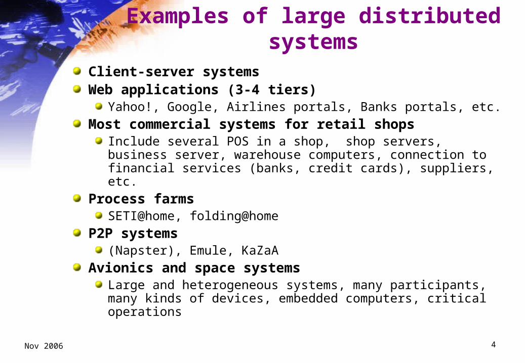
Examples of large distributed systems
Client-server systemsWeb applications (3-4 tiers)
Yahoo!, Google, Airlines portals, Banks portals, etc.
Most commercial systems for retail shopsInclude several POS in a shop, shop servers, business server, warehouse computers, connection to financial services (banks, credit cards), suppliers, etc.
Process farmsSETI@home, folding@home
P2P systems (Napster), Emule, KaZaA
Avionics and space systemsLarge and heterogeneous systems, many participants, many kinds of devices, embedded computers, critical operations

Nov 2006 5
Open systems
A system is open if its specifications are available
This include making available information about:The standards it conforms to (international or de-facto)
The software architecture of the system
The interfaces required to interoperate with the system, exchange information with it, and extend it
Open systems are independently extensible
Open systems are different from open source systemsNone of these implies the other
Open systems are not necessarily distributed systemsBut here we will deal with Open and Distributed Systems
Nov 2006 6
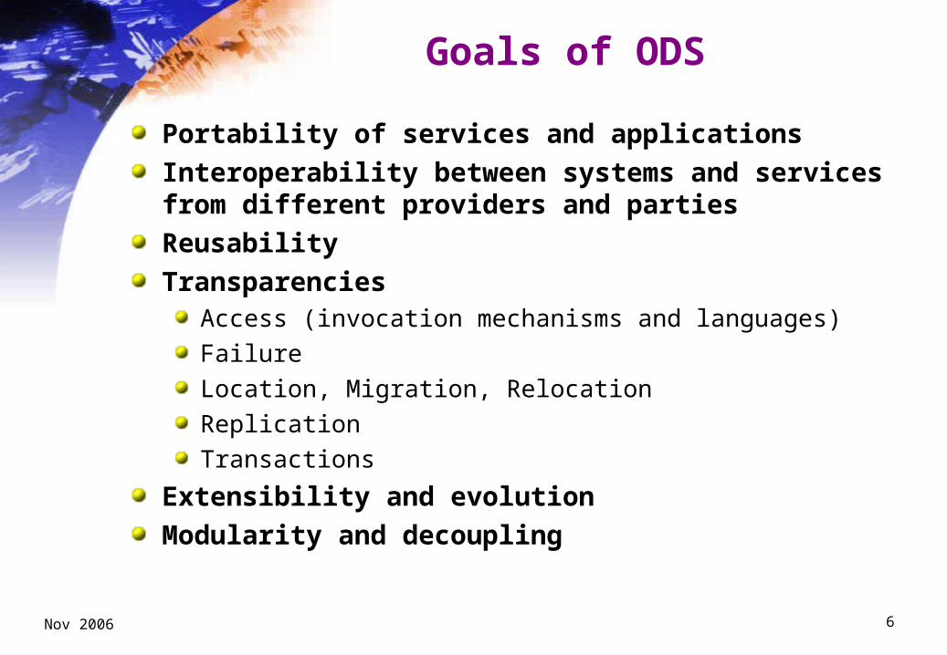
Goals of ODS
Portability of services and applications
Interoperability between systems and services from different providers and parties
Reusability
TransparenciesAccess (invocation mechanisms and languages)
Failure
Location, Migration, Relocation
Replication
Transactions
Extensibility and evolution
Modularity and decoupling
Nov 2006 7
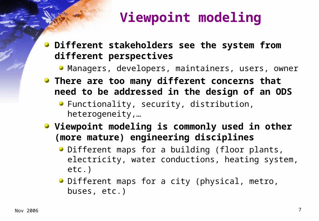
Viewpoint modeling
Different stakeholders see the system from different perspectives
Managers, developers, maintainers, users, owner
There are too many different concerns that need to be addressed in the design of an ODS
Functionality, security, distribution, heterogeneity,…
Viewpoint modeling is commonly used in other (more mature) engineering disciplines
Different maps for a building (floor plants, electricity, water conductions, heating system, etc.)
Different maps for a city (physical, metro, buses, etc.)

Nov 2006 8
Viewpoint modeling initiatives
Based on IEEE Std. 1471This standards defines the main concepts and sets the global picture
Commonly used in most modeling approachesUML (structural view, behavioural view)
Web Engineering (Navigation, Presentation, Data, Process, etc.)
MDA (CIM, PIM, PSM)
…
Main proposals for Enterprise ArchitectureKruchten’s “4+1 views”
Zachman’s framework
DoD’s TOGAF
ISO/IEC and ITU-T’s RM-ODP

Nov 2006 9
IEEE Std. 1471 (2000)
“IEEE Recommended Practice for Architectural Description of Software-Intensive System”Scope1. Expression of the system and its evolution2. Communication among the system stakeholders3. Evaluation and comparison of architectures in a consistent manner4. Planning, managing, and executing the activities of system
development5. Expression of the persistent characteristics and supporting principles
of a system to guide acceptable change6. Verification of a system implementation’s compliance with an
architectural description7. Recording contributions to the body of knowledge of software-intensive
systems architecturePurpose
“To facilitate the expression and communication of architectures and thereby lay a foundation for quality and cost gains through standardization of elements and practices for architectural description.”

Nov 2006 10
IEEE 1471 Main concepts
Architect: The person, team, or organization responsible for systems architecture.
Architectural description: A collection of products to document an architecture.
Architecture: The fundamental organization of a system embodied in its components, their relationships to each other, and to the environment, and the principles guiding its design and evolution.
System: A collection of components organized to accomplish a specific function or set of functions.
View: A representation of a whole system from the perspective of a related set of concerns.
Viewpoint: A specification of the conventions for constructing and using a view. A pattern or template from which to develop individual views by establishing the purposes and audience for a view and the techniques for its creation and analysis.

Nov 2006 11
IEEE 1471 conceptual model of architectural description

Nov 2006 12
IEEE 1471 viewpoints
An AD shall identify the viewpoints selected for use, and include a rationale for the selection of each viewpointEach viewpoint shall be specified bya) A viewpoint name,b) The stakeholders to be addressed by the viewpoint,c) The concerns to be addressed by the viewpoint,d) The language, modeling techniques, or analytical methods to be used in
constructing a view based upon the viewpoint,e) The source, for a library viewpoint (the source could include author, date,
or reference to other documents).
A viewpoint specification may include additional information:Formal or informal consistency and completeness tests to be applied to the models making up an associated viewEvaluation or analysis techniques to be applied to the modelsHeuristics, patterns, or other guidelines to assist in synthesis of an associated view
Nov 2006 13
Viewpoint completeness and consistency
An architectural description is consistent if none of its views imposes contradictory requirements on the rest of the viewpoints
An architectural description is complete if it contains all the information required by the different kinds of stakeholders
Nov 2006 14
Viewpoint examples
UML viewsRequirements, Structure, Behaviour, Deployment
Web Engineering viewpointsNavegation (hypertext)
Presentation (and adaptation)
Business Logic (processes)
MDAComputation Independent Viewpoint (CIMs)
Platform Independent Viewpoint (PIMs)
Platform Specific Viewpoint (PSMs)

Nov 2006 15
Krutchen’s “4+1 view model”
Nov 2006 16
Krutchen views
The logical view is the object model of the design (when an object-oriented design method is used),The process view captures the concurrency and synchronization aspects of the design,The physical view describes the mapping(s) of the software onto the hardware and reflects its distributed aspect,The development view describes the static organization of the software in its development environmentThe scenarios illustrate the system requirements and its basic functionality by means of use cases
Scenarios are used at the beginning to capture the system requirements, to identify the mayor elements of the system, and at the end to illustrate and validate the system design
Correspondences show how elements in one view relate to elements in other views

Nov 2006 17
Considerations about the “4+1 view model”
It prescribes the viewpoints that should compose the architectural description of a system
Not all views are required in all casesE.g., for small systems
It is methodology-independentAlthough IBM used it as the basis for RUP (v1)
It is also notation-independentUML supports well its views (apart from the development view)

Nov 2006 18
Zachman’s framework
Nov 2006 19
Considerations about the Zachman Framework
It prescribes the viewpoints that should compose the architectural description of a system
It is very detailedProbably too much!
It means at least 36 high-level models for an application
Zachman thinks all views are required in all casesEven for small systems
It is methodology-independentThe Popkin process tries to fill this gap
It is also notation-independentSowa tried to formalize some of the views
Nov 2006 20
ODP Framework
The Reference Model of ODP (ITU-T Rec X.901-904 | ISO/IEC 10746) defines a framework for system specification, covering all aspects of open distributed systems:
“enterprise” context, data, functionality, distribution, technology
It comprisesA structure for system specifications in terms of viewpointsA set of object-oriented foundation modeling concepts common to all viewpoint languagesA language (concepts and rules) for expressing each viewpoint specificationA set of correspondences between the viewpointsA set of common functionsA set of transparenciesA set of conformance pointsA framework for ODP standards

Nov 2006 21
ODP Viewpoints
Different abstractions of the same systemeach abstraction focuses on different concerns
each abstraction achieved using a set of viewpoint concepts and rules
A viewpoint specification Is a specification of a system from a specific viewpoint
is expressed in terms of the viewpoint concepts and rules (the viewpoint language) to describe the concerns and decisions covered by the viewpoint specification
Is related to, and consistent with, other viewpoint specifications (correspondences)

Nov 2006 22
ODP Viewpoints—different concerns
SystemSystem
EnterpriseEnterprise
ComputationalComputational
InformationInformation
TechnologyTechnology
EngineeringEngineering

Nov 2006 23
An ODP system specification
- Object configuration- Interactions between objects at interfaces
Computational
Enterprise- business aspects- What for? Why? Who? When?
- information- changes to information- constraints
Information
- Hardware and software components implementing the system
Technology
Engineering
- Mechanisms and services for distribution trans- parencies and QoS constraints.
- and correspondences between specifications

Nov 2006 24
ODP Correspondences
Enterprise
Information Computational Engineering Technology
Nov 2006 25
The enterprise specification
Specifies the roles played by the system in its organizational environmentAn object model of, for example, part of some social/commercial organization in terms of:
Communities (of enterprise objects)ObjectivesEnterprise objectsBehaviour
• Roles (fulfilled by enterprise objects in a community) • Processes (leading to Objectives)
PoliciesAccountability
The system is just another object

Nov 2006 26
Example: A Bank Information System
A bank is composed of branches, spread all over the country
The bank’s central office manages and coordinates the branches’ activities
Each branch has a manager and is responsible to provide banking services to its customers
Branches may interact with each other and with the bank central office
Each branch will have an ATM and a main server, and each branch’s employee will have a computer and a printer
The Bank information system (BIS) will manage all IS-related issues
Nov 2006 27
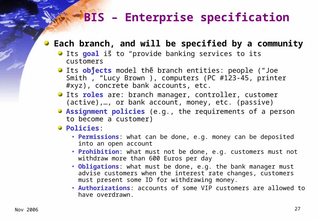
BIS – Enterprise specification
Each branch, and will be specified by a communityIts goal is to “provide banking services to its customers”Its objects model the branch entities: people (“Joe Smith”, “Lucy Brown”), computers (PC #123-45, printer #xyz), concrete bank accounts, etc.Its roles are: branch manager, controller, customer (active),…, or bank account, money, etc. (passive)Assignment policies (e.g., the requirements of a person to become a customer)Policies:
• Permissions: what can be done, e.g. money can be deposited into an open account
• Prohibition: what must not be done, e.g. customers must not withdraw more than 600 Euros per day
• Obligations: what must be done, e.g. the bank manager must advise customers when the interest rate changes, customers must present some ID for withdrawing money.
• Authorizations: accounts of some VIP customers are allowed to have overdrawn.
Nov 2006 28
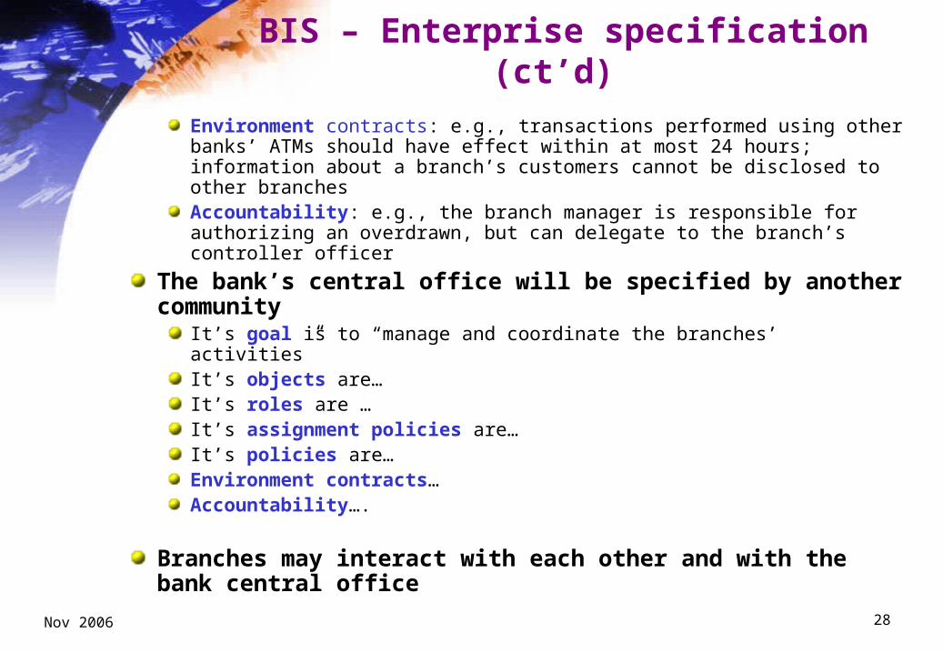
BIS – Enterprise specification (ct’d)
Environment contracts: e.g., transactions performed using other banks’ ATMs should have effect within at most 24 hours; information about a branch’s customers cannot be disclosed to other branchesAccountability: e.g., the branch manager is responsible for authorizing an overdrawn, but can delegate to the branch’s controller officer
The bank’s central office will be specified by another community
It’s goal is to “manage and coordinate the branches’ activities”It’s objects are…It’s roles are …It’s assignment policies are…It’s policies are…Environment contracts…Accountability….
Branches may interact with each other and with the bank central office

Nov 2006 29
The information specification
Specifies system behavior to fulfill its enterprise roles, abstracted from implementation An object model of the system describing the semantics of information and of information processing in the system, in terms of:
Information objectsInvariant schema: predicates on information objects that must always be true Static schema: state of information objects at some location in timeDynamic schema: allowable state changes of information objects

Nov 2006 30
BIS – Information specification
Describes a model with the information types, their relationships, and constraints on these types and relationships
e.g., a bank account consists a balance and the “amount-withdrawn-today”.Static schema captures the state and structure of a object at some particular instance
e.g., at midnight, the amount-withdrawn-today is 0.An invariant schema restricts the state and structure of an object at all times
e.g., the amountwithdrawn-today is less than or equal to 600.A dynamic schema defines a permitted change in the state and structure of an object
e.g. a withdrawal of $X from an account decreases the balance by $X and increases the amount-withdrawn-today by $X.
Static and dynamic schema are always constrained by invariant schemata
$400 could be withdrawn in the morning but an additional $200 could not be withdrawn in the afternoon as the amount-withdrawn-today cannot exceed $500.
Schemas can also be used to describe relationships or associations between objects
e.g., the static schema “owns account” could associate each account with a customer.

Nov 2006 31
The computational specification
Specifies computational structure of the system in terms of units of functionality (distribution and technology independent)An object model of the system describing the structure of processing in terms of:
Computational objectsInterfaces (of computational objects): functions supportedInvocations (by computational objects): functions invokedComputational bindings Environment contracts (e.g., QoS constraints)

Nov 2006 32
BIS – Computational specification
Objects in a computational specification can be application objects (e.g. a bank branch) or ODP infrastructure objects (e.g. a type repository or a trader)
Objects interact at well defined interfaces, using signals, operations or flows.
BankTeller = Interface Type {
operation Deposit (c: Customer, a: Account, d: Dollars)
returns OK (new_balance: Dollars)
returns Error (reason: Text);
operation Withdraw (c: Customer, a: Account, d: Dollars)
returns OK (new_balance: Dollars)
returns NotToday (today: Dollars, daily_limit: Dollars)
returns Error (reason: Text);
}
Nov 2006 33
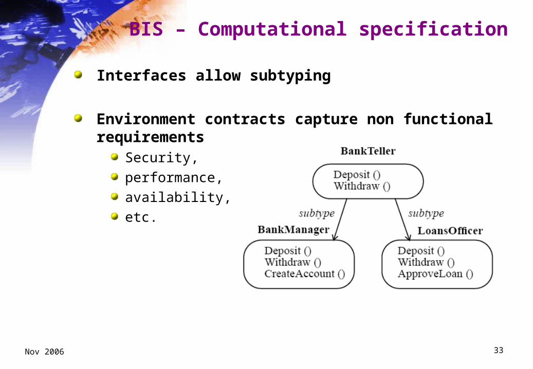
BIS – Computational specification
Interfaces allow subtyping
Environment contracts capture non functional requirements
Security,
performance,
availability,
etc.
Nov 2006 34
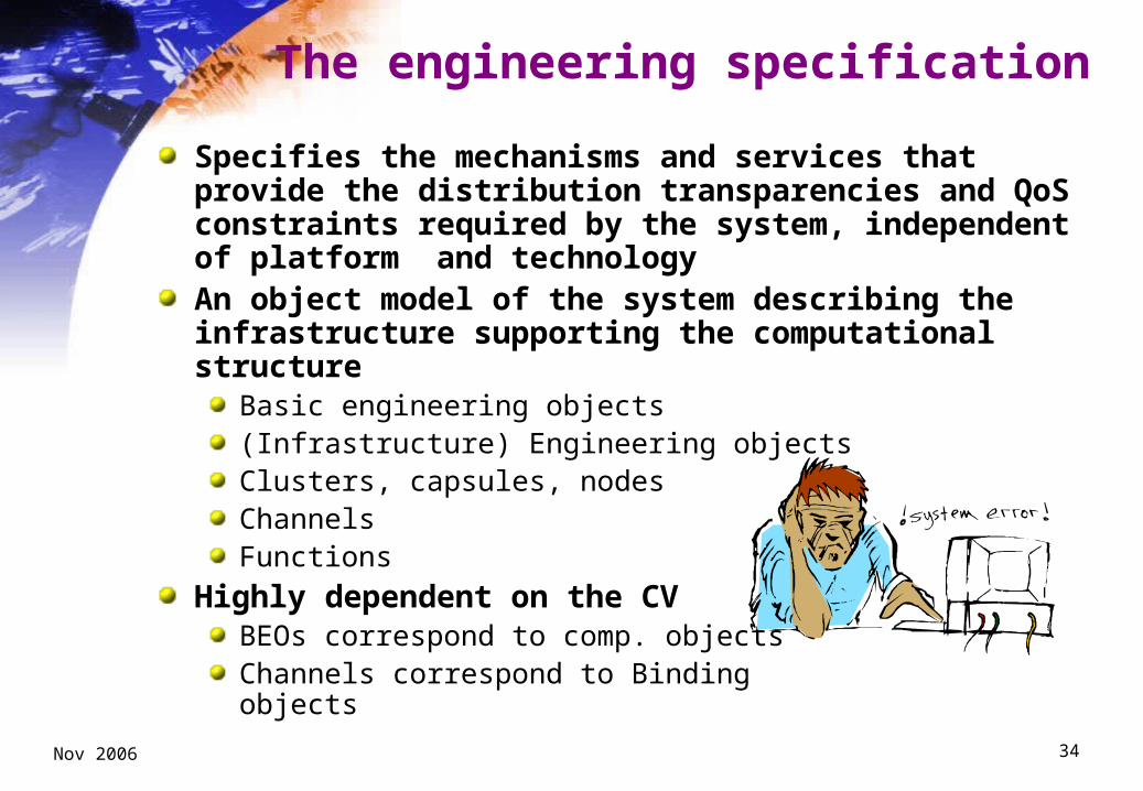
The engineering specification
Specifies the mechanisms and services that provide the distribution transparencies and QoS constraints required by the system, independent of platform and technologyAn object model of the system describing the infrastructure supporting the computational structure
Basic engineering objects(Infrastructure) Engineering objects Clusters, capsules, nodes ChannelsFunctions
Highly dependent on the CVBEOs correspond to comp. objectsChannels correspond to Bindingobjects

Nov 2006 35
Grouping concepts

Nov 2006 36
Channel structure
Nov 2006 37
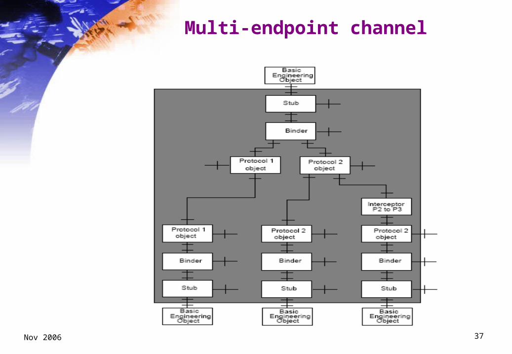
Multi-endpoint channel

Nov 2006 38
The technology specification
Specifies the H/W and S/W pieces from which the system is built
An object model of the systemdefining the configuration of technology objects that comprise the ODP system, and the interfaces between them
identifying conformance points

Nov 2006 39
BIS – Technology specification
Technology object typesTypes of PCs, servers, ATMs, printers
Types of Operating Systems and Applications (text editors, etc)
Types of connections (LANs, WANs, Intranets, etc.)
Technology selection processProviders’ selection and contracts
Conformance points
Compliance tests
Implementation, deployment, maintenance, evolutionDeployment plans
Configuration guides
Evolution plans

Nov 2006 40
ODP Correspondences, Common Functions and Transparencies
CorrespondencesAn ODP specification of a system is composed of five views and a set of correspondences between themCorrespondences do not belong to any viewODP distinguishes two kinds of correspondences
• Required correspondences• Correspondence statements
Common functionsAn ODP specification can make use of some of the common functions defined by the RM-ODP. They are “standard”
TransparenciesAn ODP specification can implement some of the transparencies defined by the RM-ODPThe specification should state which ones are used, and how they are implemented

Part II – Models, UML and DSLs
Antonio Vallecillo
Universidad de MálagaDpto. Lenguajes y Ciencias de la Computación
http://www.lcc.uma.es/~av/
Nov 2006 42
Model Driven Development (MDD)
An approach to software development in which the focus and primary artifacts of development are models (as opposed to programs) and model transformations
(compare with current language-driven approaches, whose first-class entities are “programs” and “compilers”)
MDD implies the (semi) automated generation of implementation(s) from models
Modeling languages are key to MDDModel transformation languages are also modeling languagesModels conform to meta-models
MDA is the OMG’s proposal for MDD, using OMG standards:
MOF, UML, OCL, XMI, QVTMOF y UML allow the definition of new families of languages

Nov 2006 43
What is a Model?
A description of (part of) a system written in a well-defined language. (Equivalent to specification.) [Kleppe, 2003]
A representation of a part of the function, structure and/or behavior of a system [MDA, 2001]
A description or specification of the system and its environment for some certain purpose. A model is often presented as a combination of drawings and text. [MDA Guide, 2003]
A set of statements about the system. [Seidewitz, 2003] (Statement: expression about the system that can be considered true or false.)

Nov 2006 44
What is a Metamodel?
A model of a well-defined language [Kleppe, 2003]
A model of models [MDA, 2001]
A model that defines the language for expressing a model [MOF, 2000]
A meta-metamodel is a model that defines the language for expressing a metamodel. The relationship between a meta-metamodel and a metamodel is analogous to the relationship between a metamodel and a model.
A model of a modelling language [Seidewitz, 2003]That is, a metamodel makes statements about what can be expressed in the valid models of a certain modelling language.

Nov 2006 45
Four-layers metamodel hierarchy
the MOFMMM
the UMLMM
a UMLmodel m
a particularuse of m
the SPEMMM
the CWMMM
another UMLmodel m’
anotheruse of m
Level M3
Level M2
Level M1
Level M0
EBN
Fthe Pascalgram
mar
a Pascalprogram
Pan ex
ecutionX
of program
P

Nov 2006 46
Four-layers metamodel hierarchy (example)

Nov 2006 47
OMG standards for modeling
MDA is MDD using OMG standardsMOF
• Meta Object facility
UML• Unified Modeling Language
OCL• Object Constraint Language
XMI
Metadata Interchange
MOF QVT• Query/View/Transformation

Nov 2006 48
MOF Metamodel (simplified)

Nov 2006 49
UML (2.0)
The Unified Modeling Language (UML) is a general-purpose visual language for specifying, constructing and documenting the artifacts of systems.
UML (2.0) defines Thirteen types of diagrams, for representing:
• The static application structure ¤ class, object, component, deployment, composite structure
• Different aspects of dynamic behavior ¤ use case, statechart, activity, interaction (collaboration, sequence, communication,
interaction overview, timing)
Three ways for organizing and managing the application modules • models, packages, subsystems
Plus a set of extension mechanisms (UML Profiles)

Nov 2006 50
UML 2.0: Four parts
Infrastructure – UML internalsMore precise conceptual base
Superstructure – User level featuresNew capabilities for large-scale systemsConsolidation of existing featuresAlignment with mature modeling languages (e.g. SDL, HMSC)Better extension capabilities (profiles)
OCL 2.0 – Constraint LanguageFull conceptual alignment with UMLA general purpose query language
Diagram interchangeFor exchanging graphical information (model diagrams)Size and relative position of diagrams elements

Nov 2006 51
OCL (Object Constraint Language)
A formal language used to describe expressions on UML models. Expressions typically specify
invariant conditions that must hold for the system being modeled, queries over objects described in a model,pre and post-conditions on actions and operationsconstraints on model elements.
When the OCL expressions are evaluated, they do not have side effects; i.e. their evaluation cannot alter the state of the corresponding executing system.OCL expressions can however be used to specify operations / actions that, when executed, do alter the state of the system. OCL expressions are all typed

Nov 2006 52
OCL expressions
context c : Company inv enoughEmployees: c.numberOfEmployees > 50

Nov 2006 53
OCL expressions (I)
context Company inv OnlyOneOver50: self.employee->select(p : Person | p.age > 50)->size()=1
context Person::income : Integerinit: parents.income->sum() * 1% -- pocket allowancederive: if underAge
then parents.income->sum() * 1% -- pocket allowance else job.salary -- income from regular job endif
context Person::getCurrentSpouse() : Personpre: self.isMarried = truebody: self.mariages->select(m | not m.ended).spouse
context Jobinv: self.employer.numberOfEmployees >= 1inv: self.employee.age > 21
Nov 2006 54
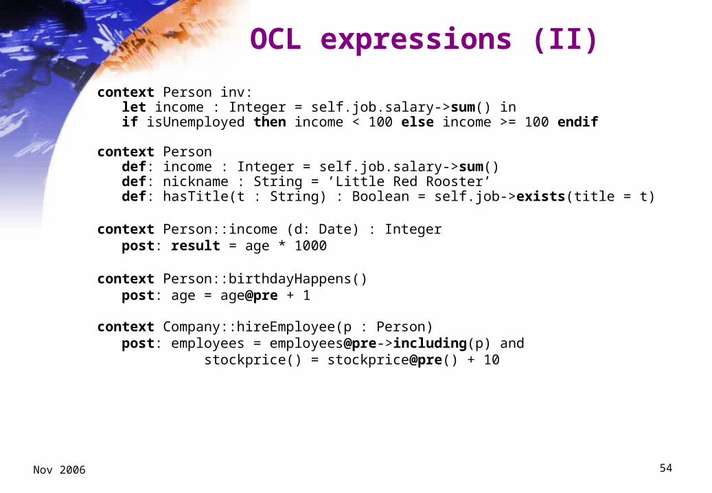
OCL expressions (II)
context Person inv:let income : Integer = self.job.salary->sum() inif isUnemployed then income < 100 else income >= 100 endif
context Persondef: income : Integer = self.job.salary->sum()def: nickname : String = ’Little Red Rooster’def: hasTitle(t : String) : Boolean = self.job->exists(title = t)
context Person::income (d: Date) : Integerpost: result = age * 1000
context Person::birthdayHappens()post: age = age@pre + 1
context Company::hireEmployee(p : Person)post: employees = employees@pre->including(p) and
stockprice() = stockprice@pre() + 10

Nov 2006 55
New (improved) alignments in 2.0

Nov 2006 56
Language definition mechanisms
Nov 2006 57
UML 2.0 Profiles
Profiles specialize UML for specific domainsWhen there is no need to change UML 2.0 metamodel and semantics, just to extend or customize them
A Profile is a metamodel conceptDefined on metamodelUsed on model
Excellent mechanism for defining MDA “Platforms” Examples:
OMG standards:• EAI: Enterprise Application Integration• EDOC: Enterprise Distributed Object Computing• CORBA, CCM• Schedulability, Performance and Time
Proprietary:• UML-RT: UML for Real Time
Nov 2006 58
UML 2.0 Extension mechanisms
StereotypesA stereotype defines how an existing metaclass may be extendedIt enables the use of platform or domain specific terminology or notation in place of, or in addition to, the ones used for the extended metaclass.UML already defines some of them (<<trace>>, <<device>>,…)
Tag definitions and tagged valuesJust like a class, a stereotype may have properties (tag definitions)When a stereotype is applied to a model element, the values of the properties are referred to as tagged valuesThey are pairs label/value {label = value}
ConstraintsA profile may define a set of (OCL) constraints on the stereotyped elements (well-formedness rules of the models defined by the extension)
Nov 2006 59
You may want to use a UML Profile to
1. Give a terminology that is adapted to a particular platform or domain (e.g. capturing some of the EJB terminology: home interfaces, enterprise java beans, archives)
2. Give a syntax for constructs that do not have a notation (such as in the case of actions)
3. Give a different notation for already existing symbols (e.g., use a picture of a computer instead of the ordinary node symbol)
4. Add semantics that is left unspecified in the metamodel (e.g., assign priorities to signals in a statemachine)

Nov 2006 60
You may want to use a UML Profile to
5. Add semantics that does not exist in the metamodel (such as defining a timer, clock, or continuous time)
6. Add constraints that restrict the way you may use the metamodel and its constructs (such as disallowing actions from being able to execute in parallel within a single transition)
7. Add information that can be used when transforming a model to another model or code (such as defining mapping rules between a model and Java code)

Nov 2006 61
Example of a UML 2.0 Profile
A profile that allows to assign colors and weights to some elements of a model
«profile» WeightsAndColors
«stereotype» Colored
color: Color
«metaclass» Class
«metaclass» Association
«enumeration» Color
«stereotype» Weighed
weight: Integer
green yellow red blue
-- Constraint: -- connected elements should -- be colored in the same color context Colored inv: self.baseClass.connection-> forAll(c | (c.extensionColored->notEmpty()) implies c.extenstionColored.color=self.color)

Nov 2006 62
Another example
We want to model the connections of a system that follows a star-shaped topology
context MyTopology::MainNode inv: self.localnodes ->forAll (n : Node | n.location = self.location) inv: self.target ->forAll(n : MainNode | n.location <> self.location)
Node *
+localnodes
1 *
MainNode
*
+target
+source
Edge
«metamodel» MyTopology
LocalEdge
location: String

Nov 2006 63
Steps to define a Profile
Define the conceptual model of the platform or domain for which we want to define the profile
For each element (concept, association) in the conceptual model:
Choose one (or more) UML elements that can be used to represent the element
Define a stereotype
Define the tag definitions of the sterotypes, using the attributes of the elements of the conceptual model
Define the Profile constraints, based on the conceptual model constraints and invariants (association multiplicities, OCL constraints)

Nov 2006 64
Profile for the Star Topology
«profile» TopologyProfile
«stereotype» Node
«stereotype» MainNode
location: String
«metaclass» Class
«metaclass» Association
«stereotype» Egde
«stereotype» LocalEdge

Nov 2006 65
Profile constraints definitions
context Node -- Connected to exactly one local edge and to no edges inv: self.baseClass.connection->select(extensionLocalEdge->notEmpty())->size()=1 and
self.baseClass.connection->select(extensionEdge->notEmpty())->isEmpty()
context LocalEgde -- all nodes it connects should have the same location inv: self.baseAssociation.connection->
select(participant.extensionNode->notEmpty())->collect(participant.extensionNode.location)->union(select(participant.extensionMainNode->notEmpty())->collect(participant.extensionMainNode.location))-> forAll(l1, l2 | l1 = l2)
inv : -- a local edge connects exactly one main nodeself.baseAssociation.connection-> select(participant.extensionMainNode->notEmpty() and
multiplicity.min=1 and multiplicity.max=1)->size()=1context Egde: -- an edge only connects main nodes inv : self.baseAssociation.connection->
select(participant.extensionNode->notEmpty())->isEmpty() and select(participant.extensionMainNode->notEmpty())->collect(participant.extensionMainNode.location)->forAll(l1, l2 | l1 <> l2)

Nov 2006 66
Use of a UML Profile
«profile»
WeightsAndColors «profile»
TopologyProfile
MyApplication
«apply» «apply»
«Node» location=”uma.es”
«MainNode, Colored» CentralOffice
«Node» Branch
«Weighed» weight=10
«LocalEdge, Weighed»
1..10 1
«MainNode» location=”uma.es” «Colored» color=red

Nov 2006 67
MOF extensions vs. Profiles
Choose a MOF extension if:The domain is well defined, with widely accepted conceptsYou do not need to combine applications from different domainsYo need to “break” the semantics of UML to represent the domain concepts
Choose a Profile if:The domain is not standard or not stableApplications from the domain can be combined with applications from other domainsYou can just “extend” the semantics of UML to represent the domain concepts

Nov 2006 68
UML 2.0 Profile Example: EJB Platform
Part IIIUML for ODP system specification
Antonio Vallecillo
Universidad de MálagaDpto. Lenguajes y Ciencias de la Computación
http://www.rm-odp.net/

Nov 2006 70
“UML4ODP”
ITU-T X.906 | ISO/IEC 19793: Use of UML for ODP system specifications
A standard defining:a set of UML Profiles for expressing a system specification in terms of viewpoint specifications
possible relationships between the resultant ODP viewpoint specifications and how they are represented
the structure of a system specification expressed as a set of UML models using ODP viewpoint profiles
“A standard that enables the use of MDA tools in developing and maintaining ODP system specifications”

Nov 2006 71
UML4ODP
Why?RM-ODP is notation- and methodology- independent
Which is an advantage (a-priori) ...
...but hampers its widespread adoption and use
Target audiencesUML Modelers
• who need to structure (somehow) their LARGE system specifications
ODP Modelers• who need some (graphical) notation for expressing their ODP
specifications and tool support
Modeling tool suppliers • who wish to develop UML-based tools that are capable of expressing
RM-ODP viewpoint specifications.
Nov 2006 72
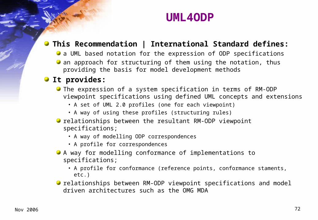
UML4ODP
This Recommendation | International Standard defines:a UML based notation for the expression of ODP specifications
an approach for structuring of them using the notation, thus providing the basis for model development methods
It provides:The expression of a system specification in terms of RM-ODP viewpoint specifications using defined UML concepts and extensions
• A set of UML 2.0 profiles (one for each viewpoint)• A way of using these profiles (structuring rules)
relationships between the resultant RM-ODP viewpoint specifications; • A way of modelling ODP correspondences• A profile for correspondences
A way for modelling conformance of implementations to specifications; • A profile for conformance (reference points, conformance staments, etc.)
relationships between RM-ODP viewpoint specifications and model driven architectures such as the OMG MDA
Nov 2006 73
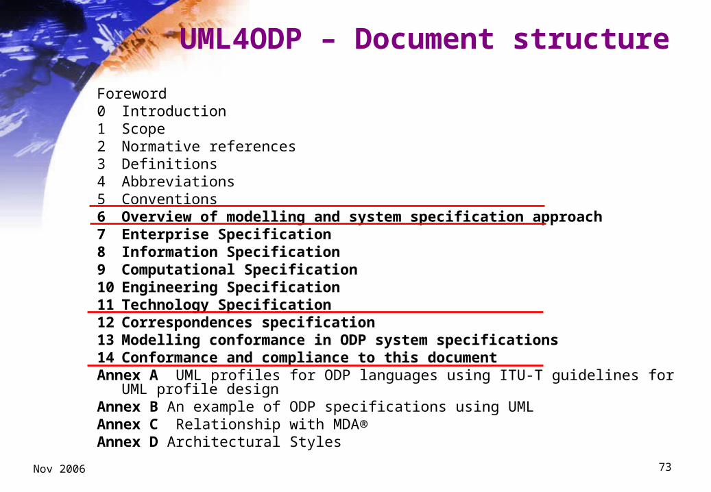
UML4ODP – Document structure
Foreword0 Introduction1 Scope2 Normative references3 Definitions4 Abbreviations5 Conventions6 Overview of modelling and system specification approach7 Enterprise Specification8 Information Specification9 Computational Specification10 Engineering Specification11 Technology Specification12 Correspondences specification13 Modelling conformance in ODP system specifications14 Conformance and compliance to this documentAnnex A UML profiles for ODP languages using ITU-T guidelines for UML profile designAnnex B An example of ODP specifications using UMLAnnex C Relationship with MDA®Annex D Architectural Styles
Nov 2006 74
UML4ODP Clause 6
6 Overview of modelling and system specification approach
6.1 Introduction
6.2 Overview of ODP concepts (extracted from RM-ODP-1)
6.3 Overview of UML concepts
6.4 Universes of discourse, ODP specs and UML models
6.5 General principles for expressing and structuring ODP system specifications using UML
6.6 Correspondences between viewpoint specifications

Nov 2006 75
UML4ODP Clause 6.4 (UoD, ODP specifications and UML models)
Universe
of Discourse
(UOD)
ODP
specification UML
model
The UML notation
models (see RM-ODP)
expresses
(UML4ODP)
represents (see UML spec)

Nov 2006 76
UML4ODP Clause 6.5(Principles for expressing and structuring ODP specs using UML)
The DSLs used to represent the viewpoint languages are defined using the UML lightweight extension mechanism (UML Profiles)
The ODP system specification will consist of a single UML model stereotyped as «ODP_SystemSpec», that contains a set of models, one for each viewpoint specification, each stereotyped as «<X>_Spec», where <X> is the viewpoint concerned
Stereotypes are used to represent domain specific specializations of UML metaclasses in order to express the semantics of the RM-ODP viewpoint language concerned
Each viewpoint specification uses the appropriate UML profile for that language, as described in Clauses 7 to 11

Nov 2006 77
ODP System specification structure

Nov 2006 78
Enterprise metamodel (excerpt 1)

Nov 2006 79
Enterprise metamodel (excerpt 2)

Nov 2006 80
Enterprise Profile: Classifiers (excerpt)

Nov 2006 81
Information Language metamodel
Nov 2006 82
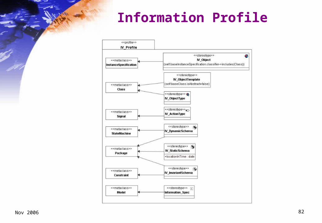
Information Profile
Nov 2006 83
UML4ODP Clause 6.6(Correspondences)
Correspondences are key to viewpoint modeling
They form part of the ODP specification of a system
Correspondences are not part of any viewpoint specification
Correspondences are expressed in UML too

Nov 2006 84
UML4ODP Clauses 7-11
X <Viewpoint> Specification
X.1 Modelling concepts• A brief description of the <viewpoint> language
• Summary of the <viewpoint> MOF-metamodel
X.2 UML Profile• Description on how the language concepts are mapped to UML, by
extending the appropriate metaclasses
• UML specification of the profile
X.3 <Viewpoint> specification structure (in UML terms)• UML packages and grouping rules
X.4 Viewpoint correspondences for the <Viewpoint> language• Description of the correspondences to other viewpoints
• Not in UML (clause 12)

Nov 2006 85
UML4ODP Clauses 12-14
12 Correspondences specification
12.1 Modelling concepts
12.2 UML Profile
13 Modelling conformance in ODP system specifications
13.1 Modelling concepts
13.2 UML profile
14 Conformance and compliance to this document
14.1 Conformance
14.2 Compliance

Nov 2006 86
Correspondence metamodel

Nov 2006 87
Correspondence Profile

Nov 2006 88
Conformance Profile

Nov 2006 89
UML4ODP Annexes
Annex A:
UML profiles for ODP languages using ITU-T guidelines for UML profile design
Annex B
An example of ODP specifications using UML
Annex C
Relationship with MDA
Annex D Architectural Styles

Nov 2006 90
Annex C: Relation with MDA

Nov 2006 91
MDA
An approach to system development using models as a basis for understanding, design, construction, deployment, operation, maintenance and modificationThree essential elements:
specifying a system independently of the platform that supports it,specifying platforms,transforming the system specification into one for a particular choice of platform.
Goals: portability, interoperability and reusabilityPrescribes the kinds of model to be used in specifying a system, how those models are prepared and the relationships between them

Nov 2006 92
What MDA does
Identifies different viewpoints on a system different abstractions - reflecting different concernsproviding a way of dealing with system complexity
Specifies 3 kinds of viewpoint model for a system:a computation independent model (CIM): a view of a system that specifies its function without specifying details of its structure a platform independent model (PIM): a view of a system that specifies its computational structure independent of any specific platform - usable with different platforms of similar type. a platform specific model (PSM): a view of a system that combines the specifications in the PIM with a specification of the use of a particular type of platform.
Specifies types of transformations between models

Nov 2006 93
What MDA does not do
MDA does not offer:
a definition of the concerns and design decisions to be covered by each MDA model
language constructs to express the concerns and decisions covered by each MDA model
…but ODP can offer:
a definition of the concerns and design decisions to be covered by each MDA model
language constructs to express the concerns and decisions covered by each MDA model

Nov 2006 94
ODP Specifications and the MDA
Business Needs
Enterprise Spec
Computational Spec
Engineering Spec
Technology Spec
Information Spec
CIM*
PIM*
PSM*
Platform Model*
Note: Terms with “*” are from MDA Guide
Transparencies
Choice of technology
Business Needs
Enterprise Spec
Computational Spec
Engineering Spec
Technology Spec
Information Spec
CIM*
PIM*
PSM*
Platform Model*
Note: Terms with “*” are from MDA Guide
Transparencies
Choice of technology

Nov 2006 95
ODP and MDA together offer
separating and integrating different system concerns
combining skills and experience
assigning responsibilities
automating development
An IT based approach to system An IT based approach to system development that provides a framework for:development that provides a framework for:

Nov 2006 96
Progress and Targets
Start of Project May 2003
SC7 WD May 2004 SC7 meeting
1st CD Dec 2004
2nd CD May-Oct 2005 SC7 meeting
FCD May 2006 WG19 meeting
FDIS? Dec 2006 WG19 meeting
Current WD is available as ISO-stds/04-06-01


