39
RULES FOR CLASSIFICATION AND CONSTRUCTION OF HIGH SPEED CRAFT PART IV STABILITY AND SUBDIVISION 2017 January GDAŃSK

RULES FOR CLASSIFICATION AND CONSTRUCTION
OF HIGH SPEED CRAFT
PART IV STABILITY AND SUBDIVISION
2017 January
GDAŃSK

RULES FOR THE CLASSIFICATION AND CONSTRUCTION OF HIGH SPEED CRAFT developed and issued by Polski Rejestr Statków S.A., hereinafter referred to as PRS, consist of the following parts:
Part I – Classification Regulations Part II – Hull Part III – Hull Equipment Part IV – Buoyancy, Stability and Subdivision Part V – Fire Protection Part VI – Machinery Equipment and Installations Part VII – Electrical Installations and Control Systems.
As regards materials and welding, the requirements specified in Part IX – Materials and Welding of the Rules for Classification and Construction of Sea-going Ships apply.
Part IV – Buoyancy, Stability and Subdivision – January 2017 was approved by PRS Executive Board on 16 November 2016 and enters into force on 1 January 2017.
From the entry into force, the requirements of Part IV apply in full to new craft.. For existing ships, the requirements of Part IV are applicable within the scope stated in Part I – Classification
Regulations.
The requirements of Part IV – Buoyancy, Stability and Subdivision are extended by the below-listed Publications:
Publication No. 6/P – Stability Publication No. 14/P – Principles of Approval of Computer Programs Publication No. 16/P – Loading Guidance Information Publication No. 32/P – Requirements Concerning Stowage and Lashing of Cargoes of Sea-going Ships Publication No. 66/P – Onboard Computers for Stability Calculations Publication No. 76/P – Stability, Subdivision and Freeboard of Passenger Ships Engaged on Domestic Voyages © Copyright by Polski Rejestr Statków S.A., 2017
PRS/OP, 11/2016

CONTENTS Page
1 General ............................................................................................................................................................. 5 1.1 Application ............................................................................................................................................... 5 1.2 General...................................................................................................................................................... 5 1.3 Definitions ................................................................................................................................................ 5 1.4 Documentation.......................................................................................................................................... 8 1.5 Scope of Survey ........................................................................................................................................ 8 1.6 General Requirements............................................................................................................................... 9 1.7 Inclining Test ............................................................................................................................................ 14 1.8 Stability Criteria........................................................................................................................................ 16 1.9 Departures from and Interpretation of Rules............................................................................................. 16 1.10 Passage beyond Specified Navigation Area.............................................................................................. 17
2 Stability and Subdivision ................................................................................................................................ 17 2.1 General...................................................................................................................................................... 17 2.2 Buoyancy .................................................................................................................................................. 18 2.3 Intact Stability in Displacement Mode...................................................................................................... 18 2.4 Intact Stability in Non-displacement Mode .............................................................................................. 19 2.5 Intact Stability in Transitional Mode ........................................................................................................ 19 2.6 Buoyancy and Stability in Displacement Mode Following Damage ........................................................ 19 2.7 Damage Extent.......................................................................................................................................... 20
3 Freeboard......................................................................................................................................................... 24 3.1 Marking and Recording Design Waterline ............................................................................................... 24 Fig. 3.1.6 .......................................................................................................................................................... 24
4 Additional Requirements................................................................................................................................ 25 4.1 Passenger Craft – mark PASSENGER ..................................................................................................... 25 4.2 Category B Passenger Craft – mark PASSENGER CATEGORY B........................................................ 26 4.3 Craft Intended for Industrial Personnel Transport – mark CREW BOAT ................................................ 27
ANNEX 1 – Stability of Hydrofoil Craft................................................................................................................ 28
ANNEX 2 – Stability of Multihull Craft ................................................................................................................ 32
ANNEX 3 – Stability of Monohull Craft................................................................................................................ 36
ANNEX 4 – Ice Accretion Applicable to all Types of Craft .................................................................................. 38


1 GENERAL
1.1 Application
1.1.1 The requirements specified in this Part IV – Stability and Subdivision (hereinafter referred to as the Rules) apply to high speed craft defined in Part I – Classification Regulations.
1.2 General
1.2.1 All craft shall fulfil the relevant requirements specified in the Rules as the condition for PRS class assignment.
1.2.2 PRS may consider the requirements for stability and subdivision as fulfilled if: .1 the stability and subdivision have been considered by the Flag State Administration to be in
accordance with requirements of that Administration and the level of these requirements is not lower than that set forth in the International Code of Safety for High Speed Craft, 2000 (HSC Code);
.2 the Owner has submitted, to PRS, a copy of the documentation approved by this Administration;
.3 the scope of the approved documentation is in accordance with the requirements specified in the Rules or is considered by PRS as sufficient.
1.2.3 For existing craft to be assigned PRS class, the scope of the requirements is specified by PRS in each particular case, having regard to the principles provided in Chapter 4 of Part I – Classification Regulations.
1.2.4 Regarding IMO conventions, codes and resolutions, referred to in the Rules, the latest versions of those documents, as amended, apply.
1.3 Definitions
General definitions and symbols are provided in Part I – Classification Regulations and Part II – Hull. For the purposes of these Rules, the following are introduced:
A f t e r p e r p e n d i c u l a r – the perpendicular, at the centre plane, at the intersection of the summer load waterline with the axis of the rudder stock.
B a s e p l a n e – horizontal plane which crosses amidships the top of a flat keel or the intersection of the inner surface of the plating with the bar keel
B r e a d t h o f c r a f t B – the maximum breadth of the ship measured amidships to the moulded line of the frame in a ship with a metal shell and to the outer surface of the hull in a ship with a shell of any other material, [m].
B u l k h e a d d e c k – the uppermost deck up to which transverse watertight bulkheads are led.
C a p s i z i n g m o m e n t Mr – conventional design moment, applied dynamically taking account of the ship’s rolling, which heels the ship to an angle equal to the angle of capsizing or the angle of flooding, or the dynamic margin angle of heel (where determined), whichever is the least, [kNm].
− C a t e g o r y A c r a f t – passenger craft operating a route where it has been demonstrated to the satisfaction of the Flag and Port States that there is a high probability that in the event of an evacuation at any point of the route, all passengers and crew can be rescued safely within the least of:
− the time to prevent persons in survival craft from exposure causing hypothermia in the worst intended conditions,
− the time appropriate with respect to environmental conditions and geographical features of the route, or
− 4 hours, and carrying more than 450 passengers.
5

C a t e g o r y B c r a f t – high-speed passenger craft other than a category A craft, with machinery and safety systems arranged such that, in the event of any essential machinery and safety systems in any one compartment being disabled, the craft retains the capability to navigate safely. The damage scenarios considered in chapter 2 shall not be inferred in this respect.
C o m p a r t m e n t – part of the ship’s inner space bounded by the ship’s bottom, sides, bulkhead deck and two adjacent transverse watertight bulkheads or the bulkhead and shell plating of the peak.
C o r r e c t e d m e t a c e n t r i c h e i g h t – the metacentric height decreased by correction for free surfaces.
C o r r e c t i o n f o r f r e e s u r f a c e s – a correction taking into account the decrease of the ship’s stability due to the effect of liquids free surface.
C r o s s c u r v e s – arms of form stability.
D e a d w e i g h t – the difference, in tonnes, between the displacement of a craft in water of a specific gravity of 1.025 t/m3 at the summer load waterline and the lightweight of the craft, [t].
D e c k h o u s e – a decked structure on the freeboard deck (or on the superstructure deck) with the sides (one or both) being inboard of the ship sides more than 0.04B.
D e s i g n w a t e r l i n e – waterline corresponding to the maximum operational weight of the craft with no lift or propulsion machinery active. D i s p l a c e m e n t m o d e – means the regime, whether at rest or in motion, where the weight of the craft is fully or predominantly supported by hydrostatic forces.
D i s p l a c e m e n t o f c r a f t D – mass of water of the volume equal to the volume of the submerged part of craft hull, [t].
D r a u g h t o f s h i p d – vertical distance measured amidships from the base plane to the summer load waterline, [m].
E q u a l i z a t i o n o f c r a f t – activities aimed at eliminating or reducing the heel and trim after flooding a compartment/compartments as a result of damage.
F o r w a r d p e r p e n d i c u l a r – the perpendicular at the intersection of the summer load waterline with the fore side of the stem. For craft with unconventional stem curvature, the position of the forward perpendicular is subject to PRS consideration in each particular case.
F r e e b o a r d d e c k – deck to which the freeboard is measured and calculated, generally it is the uppermost complete deck exposed to weather and sea, which has permanent means of closing all openings in the weather part thereof, and below which all openings in the sides of the ship are fitted with permanent means of weathertight closing.
F u l l y s u b m e r g e d f o i l – foil having no lift components piercing the surface of the water in the foil-borne mode.
H e e l i n g m o m e n t MW – design moment causing the craft heel due to dynamic pressure of wind, [kNm].
H o m o g e n e o u s c a r g o – cargo having constant stowage factor.
I n c l i n i n g t e s t – test performed to determine the lightweight of the craft and the position of its centre.
I n t a c t c r a f t d o w n f l o o d i n g a n g l e – the minimum angle of heel at which the internal spaces of craft are being flooded by outboard water through the openings – considered to be open – in hull, superstructures or deckhouses.
L i g h t c r a f t – craft ready for operation, but without cargo, stores, ballast water, passengers, crew and their effects. The mass of the media (e.g. fresh water, CO2, dry chemical powder for fire-extinguishing systems, foam concentrate) of fixed fire extinguishing systems shall be included in the lightweight of the craft and in the „light craft” loading condition.
6

L i g h t w e i g h t c h e c k – test performed to determine the lightweight of the craft and the longitudinal position of its centre.
M i d s h i p s e c t i o n – hull cross-section by the vertical plane, perpendicular to the plane of symmetry, at the middle of the distance between the forward perpendicular and after perpendicular.
M i n i m u m d r a u g h t o f c r a f t dmin – the minimum average draught of the ship without cargo, with 10% stores, including such water ballast as may be necessary, [m].
M o n o - h u l l c r a f t – craft which is not a multi-hull craft. M o u l d e d d e p t h o f c r a f t H – vertical distance measured amidships from the base plane to the top of the uppermost continuous deck beam at side. In craft having a rounded gunwale, the moulded depth is to be measured to the point of intersection of the moulded lines of the deck and side. If the uppermost continuous deck is stepped and the raised part of the deck extends over the point at which the moulded depth is to be determined, the moulded depth is to be measured to a line of reference extending from the lower part of the deck along a line parallel with the raised part, [m].
M u l t i h u l l c r a f t – craft which in any normally achievable operating trim or heel angle, has a rigid hull structure which penetrates the surface of the sea over more than one discrete area.
N o n - d i s p l a c e m e n t m o d e – normal operational regime of a craft when non-hydrostatic forces substantially or predominantly support the weight of the craft.
P a s s a g e o u t s i d e t h e a s s i g n e d a r e a o f n a v i g a t i o n – the ship’s navigation outside the assigned area of navigation after the specified requirements have been fulfilled and based on the permit granted in each particular case.
P e r m e a b i l i t y of space – the ratio of the volume which can be occupied by water to the whole volume of the space.
R o l l s t a b i l i z a t i o n s y s t e m – a special active or passive equipment for reducing the craft rolling amplitude.
S i g n i f i c a n t w a v e h e i g h t – average height of one third of the highest observed wave heights over a particular period, [m].
S i s t e r c r a f t – craft built by the same shipyard according to the same technical documentation.
S k i r t – downwards extending, flexible structure used to contain or divide an air cushion.
S t a b i l i t y b o o k l e t – document containing reliable information enabling the master, by rapid and simple processes, to obtain accurate guidance as to the stability of the ship in any loading condition.
S t o r e s – fuel oil, fresh water, provision, lubricating oil, consumables necessary for the ship operation.
S u p e r s t r u c t u r e – decked structure on the freeboard deck, extending from side to side of the ship or with one side or both sides being inboard of the ship sides not more than 0.04B. Raised quarter deck is considered as a superstructure.
S u b d i v i s i o n – craft capability of maintaining buoyancy and stability in accordance with the requirements specified in Part IV of the Rules after the damage or flooding of a single compartment, or a group of adjacent compartments.
U p p e r d e c k ( w e a t h e r d e c k ) – the uppermost continuous deck extending over the full length of the ship.
V o l u m e o f d i s p l a c e m e n t ∇ – volume of the submerged part of craft hull, [m3].
7

1.4 Documentation
1.4.1 Depending on the craft construction stage, the documentation, as specified in 1.4.1.1 and 1.4.1.2, shall be submitted to the PRS for consideration.
1.4.1.1 Prior commencement of the craft construction or alteration, the following shall be submitted to PRS for reference:
.1 General arrangement plan;
.2 Arrangement plan of outer doors, companionways and sidescuttles;
.3 Body lines or the body lines table;
.4 Hydrostatic curves, cross curves of stability – print-outs of calculation results where computer programs, not approved by PRS, are used;
.5 Calculations of: heeling levers due to the effect of wind (without icing and with icing), including the windage area diagram, flooding angles, icing (the mass of ice and the position of the centre of mass), liquid free surface effect on the ship’s stability;
.6 Plan of cargo compartments, tanks, including sounding tables and the plan of cargo decks with particulars of its loading area (cargo sections) as well as coordinates of its geometrical centres;
.7 Plan of permanent ballast, where provided; and for acceptance (preliminary approval):
.8 Preliminary Stability Booklet;
.9 Preliminary Damage Control Plan.
1.4.1.2 Upon completion of the craft construction or alteration, the following shall be submitted to PRS for approval:
.1 Stability Booklet prepared on the basis of the inclining test data (see 1.7); and for information:
.2 Inclining test report, accepted by PRS Surveyor;
.3 Updated documentation, referred to in 1.4.1.1.1 to 1.4.1.1.7 (if changes have been introduced thereto);
.4 Stability Booklet;
.5 Damage Control Plan;
1.4.2 Where provision has been made on board for anti-rolling devices or other arrangements having effect on the craft stability (e.g. anti-heeling system in port during loading/unloading operations), the scope of additional documentation and calculations shall be agreed with PRS.
1.5 Scope of Survey
1.5.1 In respect of stability PRS survey covers:
1.5.1.1 Prior to the commencement of craft construction: .1 consideration of the craft stability documentation and verification of calculations; .2 acceptance of the Preliminary Stability Booklet; .3 consideration and approval of cross-flooding fittings, if any.
1.5.1.2 During and upon the completion of craft construction: .1 acceptance of the hull measurement results (the main dimensions, keel position) and the survey
of draught marks location; .2 supervision of the inclining test and the acceptance of inclining test report; .3 consideration and approval of the Stability Booklet; .4 approval of the software for checking the craft stability while in service; .5 verifying the operation of instruments for checking the craft stability while in service; .6 checking the compliance with the hull watertight integrity requirements.
1.5.1.3 Within the scope of the craft periodical and occasional surveys: .1 checking the validity of Stability Booklet and loading plans considering the possible changes of
the craft lightweight; .2 verifying the operation of instruments for checking the ship stability prior to its departure;
8
.3 for passenger craft – lightweight survey to verify the light craft parameters (the craft mass and its longitudinal centre), performed to confirm the validity of Stability and Subdivision Booklet to be available on board the craft (see 1.7.4);
.4 checking the compliance with the hull watertight integrity requirements.
1.5.1.4 During and upon the completion of craft construction: .1 examination of the structural means and devices associated with ensuring the watertight integrity
of compartments and the craft stability after flooding a compartment/compartments; .2 approval of the Stability and Subdivision Booklet; .3 approval of the Damage Control Plan and associated Damage Control Manual; .4 checking the correctness of the assignment and marking of subdivision load lines taking account
of the requirements for the freeboard assignment.
1.6 General Requirements
1.6.1 General Assumptions and Principles
1.6.1.1 Compliance with the stability criteria does not provide immunity against capsizing and does not absolve the master from his responsibility for the safety of the ship. An additional requirement to ensure the safety of the ship, her crew and passengers is the ship proper operation taking account of the prevailing circumstances.
1.6.1.2 It is assumed that the master will operate the craft with prudence and good seamanship, with due regard paid to the season of the year, weather forecasts and the navigational zone and will take appropriate action as to speed and course warranted by the prevailing circumstances.
1.6.1.3 It is assumed that the cargo is properly stowed and secured so as to minimize the possibility of longitudinal and transverse shifting, while at sea, under the effect of acceleration caused by rolling and pitching.
1.6.1.4 It is assumed that the ship is so loaded and ballasted (where necessary) that the stability criteria, specific to a particular ship, are fulfilled at all times during a voyage.
1.6.1.5 The number of partially filled tanks shall be kept to a minimum due to their adverse effect on the ship stability.
1.6.2 Calculation Methods
1.6.2.1 It is recommended that calculations should be made using the software approved by PRS in accordance with Publication No. 14/P – Principles of Approval of Computer Programs.
1.6.3 Calculation of Hydrostatic Curves and Cross Curves of Stability
1.6.3.1 Hydrostatic and stability curves shall be calculated on a design trim basis. However, where the operating trim or the form and arrangement of the craft are such that change in trim has an appreciable effect on righting levers, such change in trim shall be taken into account.
1.6.3.2 When calculating cross curves of stability, account may be taken of those tiers of the enclosed superstructures which fulfil the requirements of 7.1.6 in Part III – Hull Equipment. Superstructures shall not be regarded as enclosed unless access is provided for the crew to reach machinery or other working spaces inside those superstructures by alternative means which are available at all times when bulkhead openings are closed.
1.6.3.3 Superstructures, in which no entrance is provided from an exposed deck above (ensuring the crew access to working spaces inside the superstructures and to the machinery space when the bulkheads openings are closed), may be taken into account in stability cross curves calculations in full height if the upper edges of door sills in superstructures at the ship’s maximum draught immerse at the angle of heel equal to or greater than the required angle of static stability range. If the upper edges of door sills in superstructures immerse at an angle less than the required angle of static stability range, the design height of superstructures shall be assumed to be half their actual height.
9

1.6.3.4 When calculating cross curves of stability, account may be taken of full height of deckhouses situated on the freeboard deck, provided they fulfil the requirements for enclosed superstructures, specified in 1.6.3.2. Where, in deckhouses, there is no exit to the deck above, such deckhouses shall not be taken into account when calculating the cross curves of stability; however, any deck openings inside such deckhouses may be considered as closed even where no means of closure are provided.
1.6.3.5 Deckhouses, the doors of which do not fulfil the requirements specified in Part III – Hull Equipment, shall not be taken into account when calculating the cross curves of stability; however, any deck openings inside the deckhouses shall be considered as closed if their coamings and means of closure fulfil the requirements specified in the relevant paragraphs of Part II – Hull and Part III – Hull Equipment.
1.6.3.6 When calculating cross curves of stability, account may be taken of the volumes of hatches, situated on the upper deck and fitted with closing devices in accordance with the requirements of Part III – Hull Equipment.
1.6.3.7 The drawing or table of cross curves of stability shall contain a scheme of superstructures and deckhouses taken into account in calculations, indicating the openings considered to be open, as well as a scheme of the part of the upper deck with the wood sheathing taken into account. The location of the point to which cross curves of stability are related shall be indicated.
1.6.3.8 Hydrostatic particulars of the ship shall be calculated for draughts measured in a range covering the light craft and maximum draughts in the displacement mode.
1.6.3.9 Hydrostatic particulars shall include at least the following: – extreme displacement in salt water (at stated density), – immersion (displacement per unit interval of draught), – moment to change trim one unit, – transverse metacentric height above the baseline, – vertical centre of buoyancy (measured from the baseline), – longitudinal centre of buoyancy, – longitudinal centre of floatation.
1.6.4 Plans of Cargo Compartments, Tanks and Decks
1.6.4.1 The plan of cargo compartments shall incorporate data, for each cargo space, containing approved permissible loading of cargo spaces, capacities, the centre of volume coordinates and data enabling to determine the centre of mass coordinates of the loaded cargo.
1.6.4.2 The plan of tanks shall incorporate all tanks other than cargo tanks, tables of volumes and the centre of volume coordinates, as well as data necessary to determine the free surface effect on stability. The plan of tanks shall be supplemented with valid sounding tables.
1.6.4.3 The plan of decks shall contain all data necessary to determine the permissible masses of deck cargoes and cargoes on hatch covers, as well as coordinates of the centres of mass.
1.6.5 Arrangement Plan of Doors, Companionways and Sidescuttles
1.6.5.1 The arrangement plan of doors and companionways shall include all doors and companionways leading to open decks, as well as all doors and hatches in the shell plating, with reference made to their drawings. The plan shall also include all sidescuttles located below the continuous upper deck, as well as sidescuttles in the superstructures and deckhouses taken into account in calculations of cross curves of stability.
1.6.5.2 Openings assumed to be open, for which angle of flooding has been determined, shall be indicated on the plan.
10

1.6.6 Windage Area Calculations
1.6.6.1 Windage area Av and its static moment shall be calculated for ship draught equal dmin. The windage area for other draughts may be calculated by linear interpolation taking the second point of the draught corresponding to the summer load waterline.
1.6.6.2 The position of the centre of the windage area shall be determined by a common method used for determining the coordinates of plane figure geometric centre.
1.6.6.3 The windage area includes the projections, on the ship centre plane, of all continuous walls and surfaces of the hull, superstructures and deckhouses, masts, ventilators, boats, deck machinery, all tents which may be put up in stormy weather, as well as the projections of lateral surfaces of cargoes to be carried on deck.
It is recommended that the windage area of discontinuous surfaces as well as the windage area of various small objects shall be taken into account by increasing the windage area calculated for draught dmin by 5% and the static moment of this area – by 10%.
In order to take into account the windage area of discontinuous surfaces and small objects under icing conditions, the projected lateral area and the static moment of this area, calculated for dmin , shall be increased by 10% and 20% or by 7.5% and 15%, respectively, depending on the mass of ice per square metre, specified in 1.6.13.2. These increased values of windage areas of discontinuous surfaces and small objects, as well as their static moments shall be assumed constant for all service draughts.
1.6.7 Effect of Free Surfaces of Liquids
1.6.7.1 Ship static stability characteristics shall take into account, for all loading conditions, the effect of free surfaces of liquids on the position of the ship’s centre of mass, the initial metacentric height and the righting levers curves.
1.6.7.2 The effect of free surfaces of liquids shall be taken into account if the filling level in a tank is less than 98% of full condition. Free surface effects of small tanks may be disregarded in conditions specified in 1.6.7.11. Nominally full cargo tanks shall be corrected for free surface effect at 98% filling level. In doing so, the correction to initial metacentric height shall be based on the inertia moment of liquid surface at 5° of heeling angle divided by displacement, and the correction to righting lever is suggested to be on the basis of real shifting moment of cargo liquids.
1.6.7.3 Tanks to be taken into consideration when determining the free surface correction may be divided into two groups:
.1 tanks with filling levels fixed (e.g. liquid cargo, water ballast);
.2 tanks with filling levels variable (e.g. fuel oil, oils, fresh water, as well as liquid cargo and water ballast during filling/discharging operations). Except cases specified in 1.6.7.5 and 1.6.7.6, the free surface correction taken shall be the maximum value attainable between the filling limits envisaged for each tank, consistent with operating instructions.
1.6.7.4 For tanks containing consumable liquids it shall be assumed that, for each type of liquid, at least one transverse pair or a single centreline tank has a free surface and the tank or a combination of tanks, taken into account in calculations, are to be those where the effect of free surfaces is the greatest.
1.6.7.5 Where water ballast tanks, as well as anti-rolling tanks and anti-heeling tanks are to be filled or discharged during the course of a voyage, the free surfaces effect shall be calculated for the most unfavourable stages of such operations.
1.6.7.6 In determining the correction to initial metacentric height, the transverse moments if inertia of the tanks shall be calculated at 0° angle of heel and divided by craft displacement (D).
1.6.7.7 Righting lever curve shall be corrected by any of the following: .1 correction based on the actual moment of fluid transfer for each angle of heel calculated; or .2 correction based on the moment of inertia, calculated at 0° angle of heel, modified at each angle
of heel calculated.
11

1.6.7.8 Corrections may be calculated in accordance with the procedure specified in 1.6.7.2.
1.6.7.9 Whichever method is selected for correcting the righting lever curve, only that method shall be presented in the ship stability booklet. However, where an alternative method is described for use in manually calculated loading condition, an explanation of the differences which may be found in the results, as well as an example correction for each alternative, shall be included.
1.6.7.10 Small tanks which fulfil the following conditions need not be included in the correction:
01,0/ min <DMfs [m]
where: Mfs – free surface moment, [tm], Dmin – minimum ship displacement calculated at dmin, [t], dmin – minimum mean service draught of ship without cargo, with 10% stores and minimum water
ballast, [m].
1.6.7.11 Residual liquids in empty tanks need not be taken into account in calculating the corrections, provided that the total of such residual liquids does not have a significant free surface effect.
1.6.8 Flooding Angle and Hull Watertight Integrity
1.6.8.1 Flooding angle of an intact ship shall be calculated based on the plan referred to in 1.6.5, taking account of the guidelines specified below.
1.6.8.2 Openings in the ship sides, decks, side walls, as well as in bulkheads of superstructures and deckhouses are assumed closed if their means of closure fulfil the requirements specified in Part III – Hull Equipment in respect of tightness, strength and effectiveness.
1.6.8.3 Small openings, such as those for passing wires and chains, tackle and anchors, as well as holes of scuppers, discharge and sanitary pipes shall not be considered as open if they submerge at an angle of heel exceeding 30°. Such openings shall be assumed open if they submerge at an angle not exceeding 30° and may be a source of significant flooding of the ship’s inner compartment taken into consideration in the stability cross curves calculations.
1.6.9 Loading Conditions
1.6.9.1 Stability and subdivision of craft shall be checked for the following loading conditions: .1 craft in the fully loaded condition, with full stores; .2 craft in the fully loaded condition, with 10% stores; .3 craft without cargo, but with full stores; .4 craft without cargo and with 10% stores.
1.6.9.2 If the loading conditions, anticipated in the craft normal service, are less favourable as regards stability than those given in 1.6.9.1 or specified in Chapter 1, then for each such loading condition the stability shall also be calculated.
1.6.9.3 If there is a permanent ballast on board, its mass shall be included in the lightweight of the ship.
1.6.9.4 If, in any loading condition, provision has been made for water ballast, such ballast shall be taken into account when calculating the stability.
1.6.10 Stability Curves
1.6.10.1 For all loading conditions considered, stability curves shall be prepared with allowance for free surface corrections (see 1.6.7).
1.6.10.2 Stability curves are considered as existing only for an angle of heel corresponding to the angle of flooding. At the angle of heel exceeding the flooding angle it shall be assumed that the ship has entirely lost its stability and the stability curves cut short at this angle.
12

1.6.10.3 If the spread of water, coming to a superstructure through openings considered to be open, is limited to this superstructure or a part thereof, such superstructure or its part shall be considered as non-existent at the angles of heel exceeding the angle of flooding. In that case, the static stability curve shall be stepped and the dynamic stability curve – broken.
1.6.11 Stability Booklet and Stability Control Means
1.6.11.1 On board the craft there shall be available reliable information and appropriate means to enable the master to obtain, by simple and rapid processes, data on the craft stability and subdivision in varying operating conditions.
1.6.11.2 Every craft shall be provided with stability booklet, approved or confirmed by PRS in accordance with the provisions of 1.2.2, containing guidelines on and principles of the craft operation in compliance with the requirements of the Rules.
1.6.11.3 Stability and Subdivision Booklet as well as the related documentation shall be drawn up in the working language of the craft. If the language used is not English and the craft is engaged on international voyages, the Stability and Subdivision Booklet shall be translated into English and approved, too.
1.6.11.4 The scope of the Stability and Subdivision Booklet shall conform to the craft type and operating conditions whereas the form and editorial quality shall take account of its intended many years’ service.
1.6.11.5 Stability and Subdivision Booklet shall include: .1 craft identification data (name of the ship, type of ship, shipyard, No. of build, date of build
(alteration), the main dimensions, number of crew, number of passengers, deadweight, navigation area, symbol of class, flag, port of registry, IMO number, maximum mean permissible draught corresponding to the summer freeboard assigned, maximum permissible draught at the forward perpendicular for the minimum bow height considerations, the minimum recommended draught at the forward perpendicular (if required));
.2 specification of stability criteria taken for stability assessment and the craft stability short characteristics
.3 guidance on loading, weather and other restrictions associated with design features or ship operation, necessary to ensure the safety of the ship as regards stability;
.4 data on the craft stability and damage stability in loading conditions required by the Rules and in operating conditions specified by the Owner (the plan of craft indicating the arrangement of cargo, stores, ballast, etc., calculations of stability and damage stability parameters, draughts, stability curves) as required in Annexes 1, 2 and 3;
.5 instructions for calculation and assessment of the craft stability in loading conditions other than those specified in the Stability and Subdivision Booklet; it is recommended that this instructions should contain a calculation example;
.6 materials and data enabling to make the necessary calculations and to assess the ship stability by a rapid and simple process;
.7 instructions concerning the proper operation of anti-rolling devices and anti-heeling system in port, as well as information on operational limits associated with the use of these arrangements and systems;
.8 plan of permanent ballast, where provided;
.9 inclining test report of the ship or of a sister ship, which was the basis for assuming the light ship parameters. Inclining test report may be issued as a separate document.
1.6.11.6 Stability and Subdivision Booklet shall be drawn up on the basis of the light ship data, specified in the valid inclining test report. In the case of a ship exempted from inclining test in accordance with 1.7.5 or 1.7.6, calculations of the lightweight of the ship and coordinates of its centre shall be given.
13

1.6.11.7 As a supplement to the approved Stability and Subdivision Booklet, computer programs may be used to facilitate calculations and checking the stability.
1.6.11.8 Stability calculation software for normal operating conditions and the possible damage shall fulfil the requirements specified in Publication No. 66/P – Onboard Computers for Stability Calculations. Such software is subject to PRS approval in each particular case.
1.6.11.9 To facilitate the ship stability assessment in operation conditions, approved by PRS instruments for the monitoring of ship stability as well as heel angle, trim and draught of ship may be used. Application of such instruments does not permit for excluding any data or recommendations required in 1.6.11.5 from the Stability Booklet.
1.6.11.10 Stability and Subdivision Booklet shall contain a statement that compliance with the requirements and recommendations specified therein, neither protects a craft against the loss of stability or capsizing, irrespective of the circumstances nor absolves the master from his duty to observe the principles of good seamanship and from the responsibility for the craft safety (see 1.6.1.1 and 1.6.1.2).
1.6.11.11 After the craft loading is complete and before the voyage commences, the master shall determine the craft trim and stability and shall make sure and enter the record that the craft fulfils the stability criteria.
1.6.12 Draught Marks
1.6.12.1 Every craft shall have scales of draughts marked clearly at the bow and stern.
1.6.12.2 Where the draught marks are not located where they are easily readable, or operational constraints for a particular trade make it difficult to read the draught marks, then the craft shall also be fitted with a reliable draught-indicating system by which the bow and stern draughts can be determined.
1.6.13 Icing
1.6.13.1 For ships intended for winter navigation within winter seasonal zones, in addition to stability calculations for the main loading conditions, stability with regard to icing shall also be checked in accordance with the requirements specified in Annex 4. The calculations shall take into account changes, due to icing, of displacement, height of the centre of mass and the centre of the windage area. The stability calculation under icing shall be performed for the loading condition most unfavourable, as regards stability. When calculating the stability under icing, the mass of ice shall be regarded as an additional mass, not included in the ship deadweight.
1.6.13.2 The mass of ice and the moment related to the base plane, calculated in accordance with the requirements specified in Annex 4, shall be taken into account as constant, irrespective of the loading condition.
1.7 Inclining Test
1.7.1 Inclining test shall be performed for: .1 every new craft; .2 craft after modification (in accordance with 1.7.2); .3 after ballast installation (in accordance with 1.7.3); .4 passenger craft, periodically (in accordance with 1.7.4).
1.7.2 After alteration, repair, re-equipment or modernization, the inclining test shall be performed for craft when even one of the following changes, verified by calculations, has taken place:
.1 deviation of the light craft displacement exceeding 2% or 2 tonnes (whichever is greater), or,
.2 deviation of the light craft longitudinal centre of gravity exceeding 1% of the craft length L, as compared with the approved and used light craft parameters, or,
.3 increase of the height of the light craft centre of gravity more than 2% or 4 cm (whichever is lesser).
14

Where the deviation of the light craft properties does not exceed the above limits, the inclining test is not required, but the valid Stability and Subdivision Booklet shall be corrected for the actual light craft parameters, calculated or obtained from the lightweight check (if performed).
Notwithstanding the submitted calculations, PRS may require lightweight check to be performed having regard to the ship age.
1.7.3 Craft in which permanent ballast has been installed shall be subjected to inclining test. The inclining test need not be performed if PRS Surveyor is convinced that the mass of the ballast and the position of its centre may be reliably determined by calculations, weighing or measurement (e.g. adding more ballast following the inclining test result).
1.7.4 PRS may allow the inclining test of a new craft, as required in 1.7.1.1, to be waived, provided the basic stability data are available from the inclining test of a sister craft and the newly built craft parameters are corrected for known differences in values of the light ship mass and longitudinal centre of gravity from the sister craft and the acceptable deviation of the light craft displacement, based on lightweight check, does not exceed:
.1 2% for craft with a length L ≤ 50 m,
.2 1% for craft with a length L ≥ 160 m, (for intermediate lengths, the acceptable deviation shall be calculated by linear interpolation), and the deviation of the light ship longitudinal centre of gravity does not exceed 0.5% of the ship length L. For further calculations, the corrected light ship parameters, based on lightweight check, shall be taken.
Where the above requirements are not fulfilled, the newly built ship shall be subjected to the inclining test.
1.7.5 The ship shall be subjected to the inclining test at the final stage of construction, modification or repair, in condition, as close as possible, to that of the light craft. The mass of the subtracted elements shall not be greater than 2% of the lightweight of the craft and the mass of the superfluous elements, without shifting ballast and water ballast defined in 1.7.7 – not greater than 4% of the craft lightweight.
1.7.6 The ship metacentric height GM during the inclining test shall not be less than 0.2 m. For this purpose, the necessary amount of ballast shall be taken. In the case of liquid ballast, the tanks shall be fully loaded.
1.7.7 To determine the angles of heel, at least two plumb lines or at least two devices, approved by PRS, and one plumb line, shall be used.
1.7.8 When the inclining test has been performed correctly, the obtained value of the metacentric height may be taken for calculations without subtracting the probable error of the test. The inclining test is considered to be correct when:
.1 for each inclination, the following requirement is fulfilled:
( )
12
2
−−
≤−n
GMGMGMGM ki
kiΣ
(1.7.9-1)
where: GMi – metacentric height obtained from a particular inclination, [m], GMk – mean metacentric height of the inclining test:
nGMGM i
kΣ= [m]
where: n – number of measurements taken. The measurements, for which the above condition is not fulfilled, are not taken into account in the repeated calculations of the metacentric height GMk. Rejecting of more than one measurement is subject to PRS consent in each particular case;
15

.2 the probable error of the test ε calculated from the formula:
( ))1(
2
−−= nn
GMGMt kin
Σε α (1.7.9-2)
fulfils the following conditions: )1(02,0 kGM+≤ε for GMk ≤ 2 m, or
kGM04,0≤ε for GMk > 2 m, where: tαn – factor determined from Table 1.7.9.2:
Table 1.7.9.2 Factor tαn
n 6 7 8 9 10 11 12 13 14 15 16
tan 6.9 6.0 5.4 5.0 4.8 4.6 4.5 4.3 4.2 4.1 4.0
.3 in the most unfavourable loading condition, as regards GM or GZm , the following condition is fulfilled:
0.04 m ≤≤1
0DDε min (0.05 GM ; 0.1 GZm )
where: D0 – light craft displacement, [t], D1 – craft displacement in the most unfavourable loading condition, [t], GM – corrected metacentric height, [m], GZm – maximum value of the static stability righting lever within the heeling angles range up to
60°, [m]; .4 the number of correct measurements is not less than 8.
1.7.9 When the requirements of 1.7.9 are not fulfilled, then, upon PRS consent, the value of the metacentric height obtained during the inclining test, with the probable error determined in accordance with 1.7.9.2 deducted, may be taken for calculations.
1.7.10 The inclining test and verification of the lightweight of the ship (1.7.4) shall be performed in the presence of PRS Surveyor and in accordance with the principles specified in Publication No. 6/P – Stability.
1.8 Stability Criteria
1.8.1 Stability and subdivision of craft in all operational loading conditions shall fulfil the general and specific (depending on the craft type) requirements contained in the Rules.
1.8.2 Craft shall have such intact stability that after the damage and flooding of one compartment it fulfils the damage stability criteria.
1.8.3 In the stability calculations, icing effect shall be taken into account, where applicable, in accordance with the guidelines contained in Annex 4.
1.8.4 The requirements contained in the Rules are the minimum requirements and reflect the safety level considered as sufficient when common general assumptions and principles are in place.
1.9 Departures from and Interpretation of Rules
1.9.1 Interpretation of the requirements and provisions, contained in Part IV is made solely by PRS.
1.9.2 At the designer’s and/or Owner’s request, PRS may, in justified cases, depart from a particular requirement or provision, provided the ship safety is not thereby impaired.
16

1.9.3 In respect of the requirements resulting from the provisions of international conventions and national regulations, departure therefrom may be accepted only in cases and in accordance with the procedure specified in the particular convention or regulations.
1.9.4 Where, with respect to any ship complying with the requirements of the present Part of the Rules, any doubt arises regarding her stability or subdivision, PRS may apply additional requirements to such a ship.
1.9.5 Where deemed necessary, PRS may enter respective records on operational limits in the approved documentation and the documents issued.
1.10 Passage beyond Specified Navigation Area
1.10.1 Craft stability during a passage beyond navigation area specified in the Certificate of Class shall fulfil the stability requirements applicable to the navigation area through which the passage is to be undertaken.
2 STABILITY AND SUBDIVISION
2.1 General
2.1.1 The requirements specified in this sub-chapter are based on the stability criteria contained in the International Code of Safety for High Speed Craft, 2000 (HSC Code).
2.1.2 Craft shall be provided with: .1 stability characteristics and stabilization systems adequate for safety when the craft is operated in
the non-displacement mode and during the transitional mode; .2 buoyancy and stability characteristics adequate for safety where the craft is operated in the
displacement mode, both in the intact condition and the damaged condition; and; .3 stability characteristics in the non-displacement and transitional modes adequate to transfer the
craft safely to displacement mode in case of any system malfunction.
2.1.3 PRS may accept other means of demonstrating compliance with the requirements with the Rules if the method chosen can be shown to provide an equivalent level of safety. Such methods ma include:
.1 mathematical simulation of dynamic behaviour;
.2 scale model testing; and
.3 full-scale trials.
2.1.4 Possibility for the mathematical simulation shall first be demonstrated by the correlation with a full-scale object or model testing for the particular type of craft. Mathematical simulation may be useful for the identification of critical scenarios for the subsequent tests.
2.1.5 Model or full-scale tests and/or calculations (as appropriate) shall also include consideration of the following known stability hazards:
.1 directional instability, which is often coupled to roll and pitch instabilities;
.2 broaching and bow diving in following seas at speeds near to wave speed;
.3 bow diving of monohulls and catamarans in the planing mode due to dynamic loss of longitudinal stability in relatively calm seas;
.4 reduction in transverse stability with increasing speed of monohulls;
.5 porpoising of planing monohulls, being coupled pitch and heave oscillations;
.6 chine tripping, being a phenomenon of planing monohulls occurring when the immersion of a chine generates a strong capsizing moment;
.7 plough-in of air-cushion vehicles, either longitudinal or transverse, as a result of bow or side skirt tuck-under or sudden collapse of skirt geometry, which, in extreme cases, can result in capsize;
.8 pitch instability of SWATH (small waterplane area twin hull) craft due to the hydrodynamic moment developed as a result of the water flow over the submerged lower hulls;
17

.9 reduction in effective metacentric height (roll stiffness) of surface effect ship (SES) in high speed turns compared to that on a straight course, which can result in sudden increases in heel angle and/or coupled roll and pitch oscillations; and;
.10 resonant rolling of SES in beam seas, which, in extreme cases, can result in capsize.
2.1.6 Suitable calculations shall be performed and/or tests conducted to demonstrate that, when operating within approved operational limitations, the craft will, after a disturbance causing roll, pitch, heave or heel due to turning or any combination thereof, return to the original attitude.
2.1.7 Where calculations are performed it shall be demonstrated that they accurately represent the craft dynamic behaviour at its operational limitations.
2.2 Buoyancy
2.2.1 All craft shall have a sufficient reserve of buoyancy at the design waterline to meet the intact and damage stability requirements of this chapter. PRS may require a larger reserve of buoyancy to permit the craft to operate in any of its intended modes. This reserve of buoyancy shall be calculated by including only those compartments which are:
.1 watertight and situated below the datum; or
.2 watertight or weathertight and situated below the datum.
2.2.2 While considering the stability after damage, flooding shall be assumed to occur until limited by watertight boundaries in the equilibrium condition, and weathertight boundaries in intermediate stages of flooding and within the range of positive righting lever required to satisfy the residual stability requirements.
2.2.3 Craft built in conformity with the requirements of organizations recognised by the Administration, in accordance with Chapter X of SOLAS may be considered to possess adequate strength and integrity.
2.2.4 Arrangements shall be provided for checking the watertight or weathertight integrity of those compartments taken into account in 2.2.1.1, and the details incorporated in the Craft Operating Manual required in paragraph 18.2.1 of the HSC Code.
2.3 Intact Stability in Displacement Mode
2.3.1 Hydrofoil craft fitted with surface-piercing foils and/or fully submerged foils shall have sufficient stability under all permitted cases of loading to fulfil the relevant requirements of Annex 1 and specifically maintain a heel angle of less than 10° when subjected to the greater of the heeling moments in 1.1.2 and 1.1.4 of that Annex.
2.3.2 Subject to 2.3.4, multihull craft other than hydrofoil craft shall fulfil the relevant requirements of Annex 2 in all permitted cases of loading.
2.3.3 Subject to 2.3.4, monohull craft other than hydrofoil craft shall fulfil the relevant requirements of Annex 3 in all permitted conditions of loading.
2.3.4 Where the characteristics of multihull craft are inappropriate for application of Annex 2 or the characteristics of monohull craft are inappropriate for application of Annex 3, PRS may accept alternative criteria equivalent to those stipulated, as appropriate to the type of craft and area of operation.
Table 2.3.4 Application of Annexes 2 and 3 to monohull and multihull craft
Angle of the maximum GZ occurrence GM [m] ≤ 25o > 25o
≤ 3,0 Annex 2 or Annex 3 Annex 3 > 3,0 Annex 2 Annex 2 or Annex 3
18
where: GZ – righting lever, [m], GM – transverse metacentric height in the loading condition corresponding to the design waterline,
corrected for free surface effects, [m].
2.4 Intact Stability in Non-displacement Mode
2.4.1 The requirements of this sub-chapter and sub-chapter 2.8.6 shall be applied on the assumption that any stabilisation systems fitted are fully operational.
2.4.2 Roll and pitch stability on the first and/or any subsequent craft of a series shall be qualitatively assessed during operational safety trials as required in Chapters 17 and 18 and Annex 9. The results of such trials may indicate the need to impose operational limitations.
2.4.3 Where craft are fitted with surface-piercing structure or appendages, precautions shall be taken against dangerous attitudes or inclinations and loss of stability subsequent to a collision with a submerged or floating object.
2.4.4 In designs where periodic use of cushion deformation is employed as a means of assisting craft control, or periodic use of cushion air exhausting to atmosphere for purposes of craft manoeuvring, the effects upon cushion-borne stability shall be determined, and the limitations on the use by virtue of craft speed or attitude shall be established.
2.4.5 In the case of an air cushion vehicle fitted with flexible skirts, it shall be demonstrated that the skirts remain stable under operational conditions.
2.5 Intact Stability in Transitional Mode
2.5.1 Under weather conditions up to the worst intended conditions, the time to pass from the displacement mode to the non-displacement mode and vice versa shall be minimised unless it is demonstrated that no substantial reduction of stability occurs during this transition.
2.5.2 Hydrofoil craft shall fulfil the relevant requirements of Annex 1.
2.6 Buoyancy and Stability in Displacement Mode Following Damage
2.6.1 The requirements specified in this sub-chapter apply to all permitted loading conditions.
2.6.2 For the purpose of making damage stability calculations, the volume and surface permeabilities shall be taken as follows:
Spaces Permeability Appropriated to cargo or stores 60 Occupied by accommodation 95 Occupied by machinery 85 Intended for liquids 0 or 95* Appropriated for cargo vehicles 90 Void spaces 95
* Whichever results in the more stringent requirements.
2.6.3 Notwithstanding 2.6.2, permeability determined by direct calculation shall be used where a more onerous condition results, and may be used where a less onerous condition results from that provided in accordance with 2.6.2.
2.6.4 PRS may permit the use of low-density foam or other media to provide buoyancy in void spaces, on condition that satisfactory evidence is provided that any such proposed medium is the most suitable alternative and is:
.1 of closed-cell form if foam, or otherwise impervious to water absorption;
.2 structurally stable under service conditions;
19

.3 chemically inert in relation to structural materials with which it is in contact or other substances with which the medium is likely to be in contact; and
.4 properly secured in place and easily removable for inspection of the void spaces.
2.6.5 PRS may permit void bottom spaces to be fitted within the watertight envelope of the hull without the provision of a bilge system or air pipes provided that:
.1 the structure is capable of withstanding the pressure head after any of the damage cases required in sub-chapter 2.6;
.2 when making a damage stability calculation in accordance with the requirements of sub-chapter 2.6, any void space adjacent to the damaged zone shall be included in the calculation and the criteria specified in 2.6, 2.8.15 and 2.9.1 shall be fulfilled;
.3 the means by which water which has leaked into the void space is to be removed shall be included in the Craft Operating Manual; and
.4 adequate ventilation is provided for inspection of the space under consideration as required in 2.2.1.4;
.5 void spaces filled with foam or other media to provide buoyancy or any spaces without vent systems are considered as void spaces for the purposes of this sub-chapter on condition that such foam or other media to provide buoyancy completely fulfil the requirements specified in 2.6.4
2.6.6 Any damage of a lesser extent than that postulated in 2.7 which would result in a more adverse condition shall also be investigated.
2.7 Damage Extent
2.7.1 Side Damage Extent
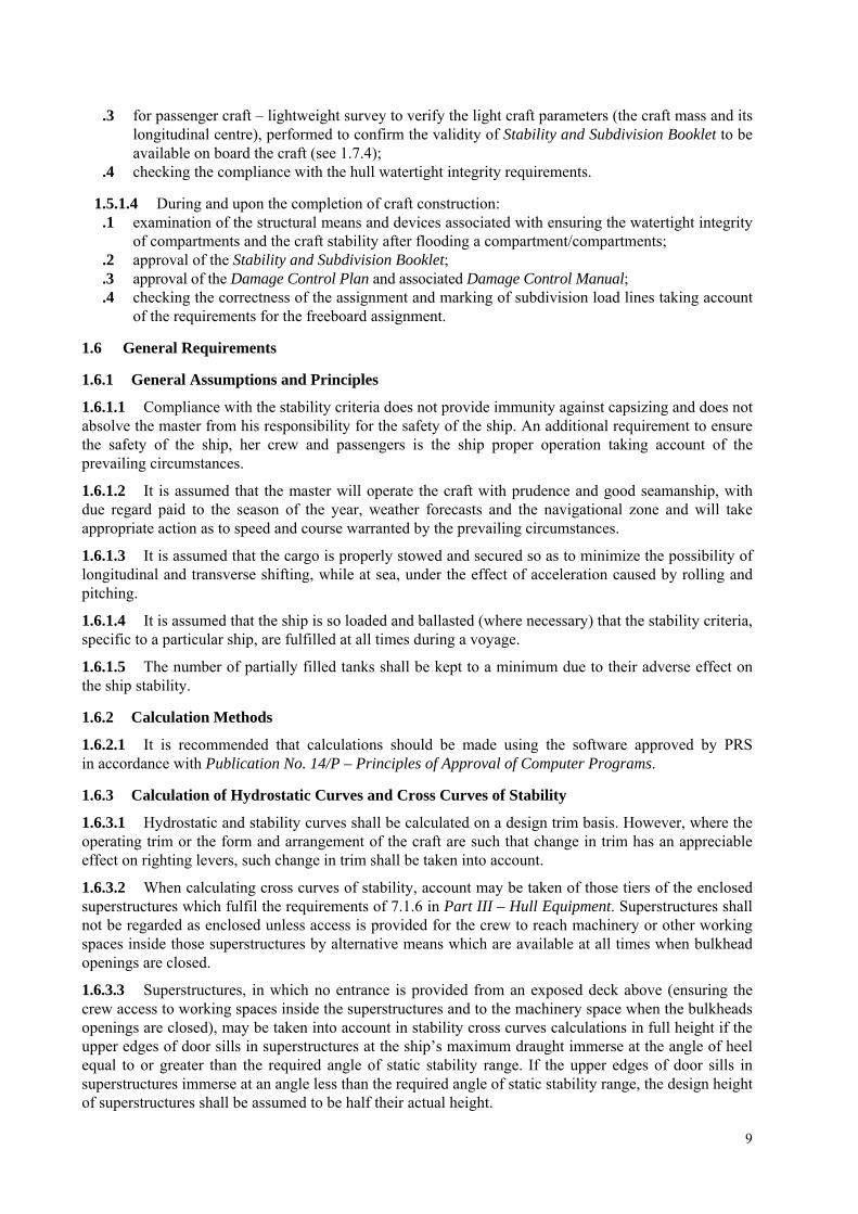
2.7.1.1 The following side damage cases shall be assumed anywhere on the periphery of the craft: .1 the longitudinal extent of damage shall be 0.75∇1/3 or (3 m + 0.225∇1/3) or 11 m, whichever is the
least; .2 the transverse extent of penetration into the craft shall be 0.2∇1/3. However, where the craft is
fitted with inflated skirts or with non-buoyant side structures, the transverse extent of penetration shall be at least 0,12∇1/3 into the main buoyancy hull or tank structure; and;
.3 the vertical extent of damage shall be taken for the full vertical extent of the craft.
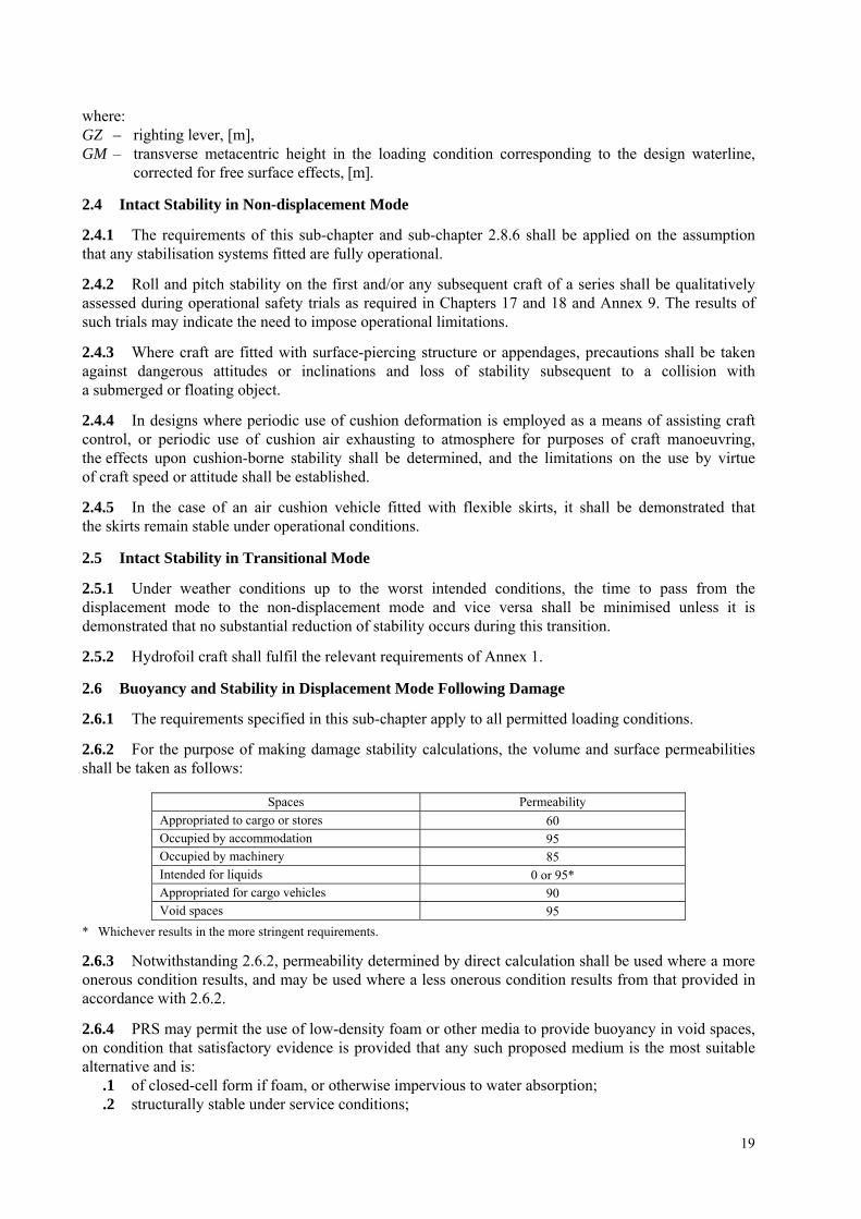
2.7.1.2 The shape of the damage shall be assumed to be a parallelepiped1. In Fig. 2.7.1.2a it is shown that the damage surface should be tangent amidships or have contact, at least in two points, the area corresponding to the specified transverse damage. The extent of side damage shall not exceed 0.2∇1/3 on the design waterline except for the cases of lesser extent of damage as provided in 2.7.1.1.2 (Figures 2.7.1.2b and 2.7.1.2c). As regards multihull craft, the craft outline is understood to be only the plating area of the extreme outer part of hull at the particular section.
1 Parallelepiped is defined as a three-dimensional figure formed by six parallelograms with three pairs of parallel faces.
20
Transverse extent of penetration
Longitudinal extent of penetration
Fig. 2.7.1.2a
Transverse extent of penetration
Design waterline
Damage extent lesser than the maximum vertical extent
Damage by penetration limited, by the vertical line, below the design waterline
Centre plane
Fig. 2.7.1.2b
Damage extent lesser than the maximum vertical extent
Design waterline
Damage by penetration limited, by the vertical line,
below the design waterline Centre plane
Fig. 2.7.1.2c
2.7.2 Extent of Damage to Bow and Stern
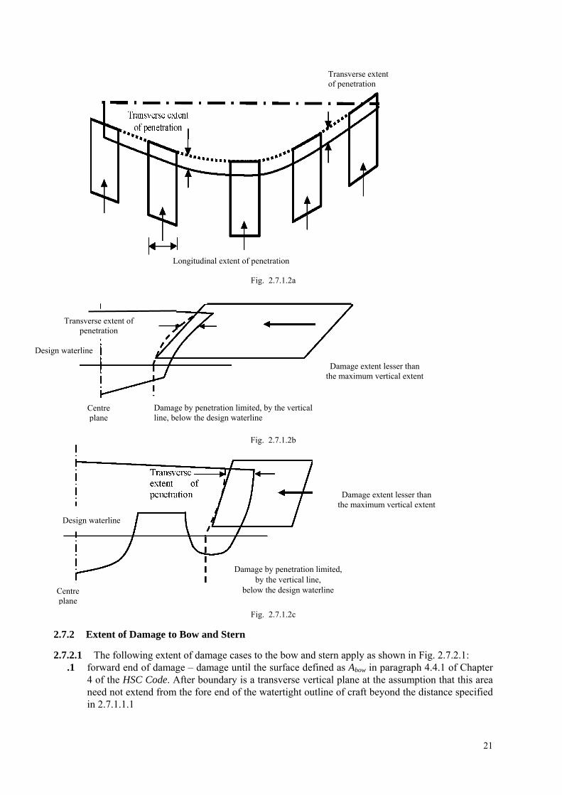
2.7.2.1 The following extent of damage cases to the bow and stern apply as shown in Fig. 2.7.2.1: .1 forward end of damage – damage until the surface defined as Abow in paragraph 4.4.1 of Chapter
4 of the HSC Code. After boundary is a transverse vertical plane at the assumption that this area need not extend from the fore end of the watertight outline of craft beyond the distance specified in 2.7.1.1.1
21

.2 after end of damage – damage until the after surface of the transverse vertical plane in the distance of 0.2∇1/3 forwards of the after end of the watertight outline of hull.
Deck area = Abow
0,2∇1/3
Transverse vertical plane
Fig. 2.7.2.1
2.7.2.2 The requirement of 2.6.6 shall apply to a damage case of lesser extent.
2.7.3 Extent of Bottom Damage in Areas Vulnerable to Raking Damage
2.7.3.1 Any part of the surface of the hull(s) is considered to be vulnerable to raking damage if: .1 it is in contact with the water at operational speed of 90% of the maximum speed in smooth
water, and; .2 it also lies below two planes which are perpendicular to the craft centreline plane and at heights
as shown in Fig. 2.7.3.1. For multihulls, individual hulls shall be considered separately.
2.7.3.2 Raking damage shall be assumed to occur along any fore-and-aft line on the surface of the hull(s) between the keel and the upper limit defined in Fig. 2.7.3.2 below.
Fig. 2.7.3.2
where: T – maximum draught of the hull (each hull to be considered individually in the case of multihulls) to
the design waterline, excluding any nonbuoyant structure, at the assumption that such structures as single skegs or solid metallic accessories are not considered as media to provide buoyancy, therefore excluded from the calculations, [m].
2.7.3.3 Damage shall not be applied at the same time as that defined in 2.7.1 and 2.7.4.
2.7.4 Damage Extent
2.7.4.1 Two different longitudinal extents shall be considered separately: .1 55% of the length L, measured from the most forward point of the underwater buoyant volume of
each hull; .2 a percentage of length L, applied anywhere in the length of the craft, equal to 35% for craft
where L ≥ 50m and equal to (L/2 + 10)% for craft with L < 50 m.
22

2.7.4.2 Except as provided below, the penetration normal to the shell shall be 0.04∇1/3 or 0.5 m, whichever is the lesser, in association with a girth along the shell equal to 0.1∇1/3. However this penetration or girth shall under no circumstances extend above the vertical extent of the vulnerable area as specified in.
2.7.4.3 It is assumed that the damaged space consists of a sequence of sections within the longitudinal extent of damage as shown in Fig. 2.7.4.3 and that the centre of a damaged perimeter is kept at the constant distance from the centre line. Penetration normal to shell
Penetration boundary
Grith along the shell
Fig. 2.7.4.3
2.7.5 Extent of Bottom Damage in Areas not Vulnerable to Raking Damage
2.7.5.1 The principles specified below apply to all parts of the hull(s) below the design waterline which are not defined as vulnerable to raking damage in 2.7.3.1. Damage shall not be applied at the same time as that defined in 2.7.1 and 2.7.3.1.
2.7.5.2 The following extent of damage shall be assumed: .1 the length of damage in the fore-and-aft direction shall be:
0.75∇1/3 or 3 m + 0.225∇1/3 or 11 m, whichever is the least;
.2 the athwartships girth of damage shall be 0.2∇1/3;
.3 the depth of penetration normal to the shell shall be 0.02∇1/3;
.4 the shape of penetration shall be taken as rectangular both coplanar with the shell and in the transverse plane as shown in Fig. 2.7.2.2.3.
2.7.5.3 In applying 2.7.3 and 2.7.4 to multihull craft, an obstruction at or below the design waterline of up to 7 m width shall be considered in determining the number of hulls damaged at any one time. The requirement of 2.6.6 shall also be applied.
2.7.5.4 Following any of the postulated damage cases detailed in paragraphs from 2.6.6 to 2.7.5, the craft in still water shall have sufficient buoyancy and positive stability to simultaneously ensure that:
.1 for all craft other than amphibious air-cushion vehicles, after flooding has ceased and a state of equilibrium has been reached, the final waterline is below the level of any opening through which further flooding could take place by at least 50% of the significant wave height corresponding to the worst intended conditions;
.2 for amphibious air-cushion vehicles, after flooding has ceased and a state of equilibrium has been reached, the final waterline is below the level of any opening through which further flooding could take place by at least 25% of the significant wave height corresponding to the worst intended conditions;
.3 there is a positive freeboard from the damage waterline to survival craft embarkation positions;
.4 essential emergency equipment, emergency radios, power supplies and public address systems needed for organizing the evacuation remain accessible and operational;
23

.5 the residual stability of craft meets the appropriate criteria as laid out in Annexes 2 and 3 according to Table 2.3.4. Within the range of positive stability governed by the criteria of Annexes 3 or 4, no unprotected opening shall be submerged.
2.7.5.5 Downflooding openings referred to in 2.7.6.1 and 2.7.6.2 shall include doors and hatches which are used for damage control or evacuation procedures, but may exclude those which are closed by means of weathertight doors and hatch covers and not used for damage control or evacuation procedures.
3 FREEBOARD
3.1 Marking and Recording Design Waterline
3.1.1 The design waterline shall be clearly and permanently marked on the craft’s outer sides by the load line mark described below. This and the reference line described in 3.1.3 below shall be recorded in the High-Speed Craft Safety Certificate. For craft where this is not practical, e.g. amphibious air-cushion vehicles fitted with peripheral skirts, defined deck reference points shall be provided, from which the freeboard can be measured, and hence the draughts obtained.
3.1.2 Load line mark shall consist of a ring with an outside diameter of 300 mm and width of 25 mm which is intersected by a horizontal line of length 450 mm and having a breadth of 25 mm, the upper edge of which passes through the centre of the ring. The centre of the ring shall be placed at the longitudinal centre of flotation in the displacement mode and at a height corresponding to the design waterline.
3.1.3 To assist in verifying the load line mark position, a reference line shall be marked on the hull at the longitudinal centre of flotation by a horizontal bar having a length of 300 mm and a breadth of 25 mm and having the upper edge corresponding to the reference line.
3.1.4 Where practicable, the reference line should be related to the uppermost deck at side. Where it is not possible, the position of the reference line should be defined from the underside of keel at the longitudinal centre of flotation.
3.1.5 The mark of the Administration by whom the load lines are assigned may be indicated alongside the load line ring above the horizontal line which passes through the centre of the ring, or above and below it. This mark shall consist of not more than four initials to identify the Administration’s name, each measuring approximately 115 mm in height, and 75 mm in width.
3.1.6 Where freeboard mark is assigned by PRS, letters P and R of 115 mm in height and 75 mm in width (Fig. 3.1.5) are placed on both sides of the ring above the horizontal line which passes through the ring centre.
3.1.7 Freeboard marks shall be readily visible. The ring, lines and letters shall be painted in white or yellow on a dark ground or in black on a light ground, and permanently marked.
RP
300
450
115
75
Fig. 3.1.6
24

4 ADDITIONAL REQUIREMENTS
4.1 Passenger Craft – mark PASSENGER
4.1.1 In addition to the requirements specified in sub-chapter 1.7, lightweight survey shall be performed on all passenger craft to verify any changes in lightweight displacement and longitudinal centre of gravity at five-year intervals. The passenger craft shall be re-inclined whenever, in comparison with the approved stability information, a deviation from the lightweight displacement exceeding 2% or 2 t (whichever is greater) and/or a deviation of the longitudinal centre of gravity exceeding 1% of the craft length, L, is found. Unless those changes exceed the above mentioned values, the inclining test is not required, however the Stability and Subdivision Booklet shall be amended by the latest lightweight paramaters of craft obtained from the lightweight check.
4.1.2 Intact Stability
4.1.2.1 Passenger craft stability shall be checked in the following loading conditions: .1 with full cargo, the full number of cabin and deck passengers together with full baggage and full
stores; the possibility of taking account of water ballast in the calculations is subject to PRS consent in each particular case;
.2 with full cargo, the full number of cabin and deck passengers together with full baggage and 10% stores;
.3 as specified in .2 above, but with 50% stores;
.4 with no cargo, the full number of cabin and deck passengers together with full baggage and full stores;
.5 as specified in .4 above, but with 10% stores;
.6 with no cargo and no passengers, with full stores;
.7 as specified in .6 above, but with 10% stores.
4.1.2.2 In stability calculations, class passengers shall be assumed to be in their accommodation spaces and unberthed passengers – on appropriate decks. The arrangement of passengers’ baggage and its mass is subject to PRS consideration in each particular case. Cargo stowage in holds on ‘tweendecks and decks shall be assumed as in normal service conditions.
Where craft ballasting is necessary, its stability shall be checked taking account of water ballast. Stability check taking account of icing shall be performed at the assumption that no passengers are on
weatherdecks.
4.1.2.3 Craft shall have such intact stability in the displacement mode that the static inclination of the craft from the horizontal would not exceed 10° for crowding of all passengers on one side (as close to the bulwark as possible) on the uppermost deck.
4.1.2.4 Intact stability in the non-displacement mode shall be such that the total heel angle in still water due to the effect of crowding of all passengers on one side and due to beam wind pressure as per 1.1.4 of Annex 1 shall not to exceed 10°. The effect of crowding of all passengers on one side need not be considered where passengers are required to be seated whenever the craft is operating in the non-displacement mode.
4.1.2.5 In all loading conditions, the outward heel due to turning shall not exceed 8°, and the total heel due to beam wind pressure as per 1.1.4 of Annex 1 and due to turning shall not exceed 12° outward.
4.1.2.6 When determining the heeling moment due to crowding of passengers to one side, the mass of each passenger shall be assumed to be 0.075 ton, the height of the centre of mass for standing passengers shall be equal to 1.0 m above the deck, that for sitting passengers – 0.3 m above the seats; the passengers distribution density: 4 persons per square metre of the deck area.
4.1.2.7 When determining the area where crowding of passengers is permitted, the passages between seats and the areas of narrow external passages between the deckhouse and the bulwark or railing up to 0.7 m wide shall be taken for calculations with the factor 0.5.
25

4.1.2.8 When establishing distribution of passengers in order to determine heeling moment Mhp, it shall be assumed that the normal craft service conditions with an allowance for the position of the equipment and machinery are maintained and the principles governing access of passengers to a particular deck area are observed; diagram of the assumed distribution of the crowding passengers shall be included in the Stability and Subdivision Booklet.
4.1.2.9 On decks where assembly stations are arranged, the number of passengers shall be such as not to induce the maximum heeling moment. The other passengers shall go to adjacent decks taking such positions that the maximum static angle of heel be achieved.
4.1.2.10 Passengers shall not be on the weatherdeck. Overcrowded fore and after peaks shall not be assumed are unless it is necessary according to the planned evacuation procedure.
4.1.2.11 Where seats are provided in the passenger area, it is assumed that one passenger occupies one seat. For passengers present in other free spaces on decks, including staircase (if any), 4 passengers shall be assumed per square meter.
4.1.2.12 The effect of heeling moment due to passengers or due to beam wind pressure during craft movement shall be demonstrated through full-scale trials or scale model testing with the equivalent heeling moment induce by the application of respective weights. Passenger movement on the craft may be disregarded only where, for safety reasons, passengers are required to be seated during all the voyage.
4.1.3 Buoyancy and Stability in Displacement Mode Following Damage
4.1.3.1 Following any of the postulated damages detailed in paragraphs from 2.6.6 to 2.7.5, in addition to satisfying the requirements of 2.7.6 and 2.7.7, the craft in still water shall have sufficient buoyancy and positive stability to simultaneously ensure that:
.1 the angle of inclination of the craft from the horizontal does not normally exceed 10° in any direction. However, where this is clearly impractical, angles of inclination up to 15° immediately after damage but reducing to 10° within 15 minutes shall be permitted provided that efficient non-slip deck surfaces and suitable holding points, e.g., holes, bars, etc., are provided; and
.2 any flooding of passenger compartments or escape routes which might occur will not significantly impede the evacuation of passengers.
4.1.3.2 In the Stability and Subdivision Booklet the following shall also be included: .1 notice on the importance to the craft safety of the protection and keeping in good order all the
watertight and weathertight means of closing for the possibility of sudden stability loss in case of water ingress onto the ro-ro deck;
.2 relevant information on maintaining the required steering qualities of the craft in the extreme weather condition expected in the operating area.
To confirm the above mentioned information, the results of test or trials shall be submitted to PRS for reference.
4.2 Category B Passenger Craft – mark PASSENGER CATEGORY B
4.2.1 In addition to the requirements in 2.8.13.1, category B craft shall also satisfy the following criteria after sustaining raking damage of 100% of length L, having the girth and penetration given in 2.7.4.1, to any part of the surface of the hull(s) defined in 2.7.3.2.2:
.1 the angle of inclination of the craft from the horizontal shall not exceed 20° in the equilibrium condition;
.2 the range of positive righting lever shall be at least 15° in the equilibrium condition;
.3 the positive area under the righting lever curve shall be at least 0.015 m.rad in the equilibrium condition;
.4 the requirements of 2.7.6.3 and 2.8.15.2 are satisfied; and
.5 in intermediate stages of flooding, the maximum righting lever shall be at least 0.05 m and the range of positive righting lever shall be at least 7°.
26

In complying with the above, the righting lever curve shall be terminated at the angle of downflooding, and only one free surface need be assumed.
4.3 Craft Intended for Industrial Personnel Transport – mark CREW BOAT
4.3.1 Depending on the number of carried industrial personnel, craft stability and subdivision shall fulfil the following requirements:
.1 craft carrying not more than 12 passengers shall fulfil the requirements specified in Chapter 2, exclusive of the detailed requirements of sub-chapter 2.8.
.2 craft carrying more than 12 passengers shall fulfil the requirements specified in Chapter 2, exclusive of the detailed requirements of sub-chapter 2.9.
27

ANNEX 1
STABILITY OF HYDROFOIL CRAFT
The stability of these craft shall be considered in the hull-borne, transitional and foil-borne modes. The stability investigation shall also take into account the effects of external forces. The following procedures are outlined for guidance in dealing with stability
Stability assessment shall be performed for all possible conditions expected in the craft normal service in accordance with paragraph 2.3.1 of the Rules.
1 Surface-piercing Hydrofoils
1.1 Hull-borne Mode
1.1.1 The stability shall be sufficient to fulfil the requirements specified in sub-chapters 2.3, 2.4 and 2.6 of the Rules.
1.1.2 Heeling Moment due to Circulation
For the ratio of the turning circle radius to craft length ranging from 2 to 4, the heeling moment developed during manoeuvring of the craft in the displacement mode may be derived from the following formula:
2
0.196 oR
VM D KGL
= ⋅ ⋅ [kNm]
where: Vo – craft speed in the turn, [m/s]; D – displacement, [t]; L – craft length on waterline, [m]; KG – height of the centre of gravity above the base plane, [m].
1.1.3 Relationship between Capsizing Moment and Heeling Moment – Weather Criterion
Hydrofoil boat stability in the displacement mode can be checked for compliance with the weather criterion K as follows:
1≥=r
c
MMK
where: Mc – minimum capsizing moment as determined when account is taken of rolling; Mr – dynamically applied heeling moment due to the wind pressure.
1.1.4 Heeling Moment due to Wind Pressure
Heeling moment MV shall be taken as constant during the whole range of heel angles and calculated by the following expression;
Mv = 0.001 Pv Av Z [kNm] where: Pv – wind pressure = 750·(Vw /26)2, [Pa]; Av – windage area including the projections of the lateral surfaces of the hull, superstructure and
various structures above the waterline, [m2]; Z – windage area lever, i.e. the vertical distance to the geometrical centre of the windage area from the
waterline, [m]; Vw – wind speed corresponding to the worst intended conditions, [m/s].
28

1.1.5 Minimum Capsizing Moment in Displacement Mode
Minimum capsizing moment in the displacement mode, MC, is determined from the static and dynamic stability curves taking rolling into account:
.1 when the static stability curve is used, Mc is determined by equating the areas under the curves of the capsizing and righting moments (or levers) taking rolling into account, as indicated in Fig. 1, where: θz – roll amplitude, [°] – determined by scale model testing and full scale trials on irregular
wave, taken as the maximum roll amplitude out of 50 roll cycles of craft moving at the angle of 90° to the wave direction at the worst expected sea conditions. Where such data are unavailable, the roll amplitude is assumed as equal 15°;
MK – line drawn parallel to the abscissa axis such that the shaded areas S1 and S2 are equal, where
MC = OM if the scale of ordinates represents moments, MC = OM × D if the scale of ordinates represents levers.
Fig. 1 Static stability curve
.2 when the dynamic stability curve is used, first an auxiliary point A shall be determined. For this purpose the amplitude of heeling is plotted to the right along the abscissa axis and a point A' is found (see Fig. 2). Line AA' is drawn parallel to the abscissa axis equal to the double amplitude of heeling (AA' = 2θz) and the required auxiliary point A is found. Tangent AC to the dynamic stability curve is drawn. From the point A the line AB is drawn parallel to the abscissa axis and equal to 1 radian (57.3°). From point B a perpendicular is drawn to intersect with the tangent in point E. Distance BE is equal to the capsizing moment if measured along the ordinate axis of the dynamic stability curve. If, however, the dynamic stability levers are plotted along this axis, BE is then the capsizing lever, and in this case the capsizing moment Mc is determined by multiplication of ordinate BE (in metres) by the corresponding displacement in tonnes.
MC = g D BE [kNm]
29

57.3° (1 radian)
Fig. 2 Dynamic stability curve
1.2 Transitional and Foil-borne Modes
1.2.1 Stability in the transitional and foil-borne modes shall be checked for all cases of loading for the intended service of the craft.
1.2.2 Stability in the transitional and foil-borne modes may be determined either by calculation or on the basis of data obtained from model experiments and shall be verified by full-scale tests by imposition of a series of known heeling moments by off-centre ballast weights, and recording the heeling angles produced by these moments. When taken in the hull-borne, take-off, steady foil-borne and settling to hull-borne modes, these results will provide an indication of the values of the stability in the various situations of the craft during the transitional condition.
1.2.3 The angle of heel in the foil-borne mode caused by the concentration of passengers at one side shall not exceed 8°. During the transitional mode the angle of heel due to the concentration of passengers on one side shall not exceed 12°. The concentration of passengers shall be determined by the Administration, having regard to the guidance given at Annex 2 to the Rules.
1.2.4 One of the possible methods of assessing foil-borne metacentric height GM in the design stage for a particular foil configuration is given in Fig. 3.
Fig. 3
⎟⎟⎠
⎞⎜⎜⎝
⎛−+⎟⎟
⎠
⎞⎜⎜⎝
⎛−= S
ILnS
ILnGM
H
HH
B
BB tan2tan2
where: nB – percentage of hydrofoil load borne by front foil, [%], B
30

nH – percentage of hydrofoil load borne by aft foil, [%], LB – clearance width of front foil, [m], B
LH – clearance width of aft foil, [m], a – clearance between bottom of keel and water, [m], g – height of centre of gravity above bottom of keel, [m], IB – angle at which front foil is inclined to horizontal, [°], B
IH – angle at which aft foil is inclined to horizontal, [°], S – height of centre of gravity above water, [m].
2 Fully Submerged Hydrofoils
2.1 Hull-borne Mode
2.1.1 Stability in the hull-borne mode shall be such as to fulfil the requirements specified in sub-chapters 2.3 and 2.6 of the Rules.
2.1.2 Paragraphs from 1.1.2 to 1.1.5 of this Annex are appropriate to this type of craft in the hull-borne mode.
2.2 Transitional Mode
2.2.1 Stability shall be examined by the use of verified computer simulations to evaluate the craft motions, behaviour and responses under the normal conditions and limits of operation and under the influence of any malfunction.
2.2.2 Stability conditions resulting from any potential failures in the systems or operational procedures during the transitional stage which could prove hazardous to the craft's watertight integrity and stability shall be examined.
2.3 Foil-borne Mode
Craft stability in the foil-borne mode shall be fulfil the requirements specified in sub-chapter 2.4 of the Rules. The requirements of sub-chapter 2.2 of this Annex also apply.
2.4 Paragraphs 1.2.2.1, 1.2.2.2 and 1.2.2.3 of this Annex apply to this type of craft as appropriate and any computer simulations or design calculations shall be verified by full-scale tests.
31

ANNEX 2
STABILITY OF MULTIHULL CRAFT
1 Stability Criteria in Intact Condition
Multihull craft, in the intact condition, shall have sufficient stability when rolling in a seaway to successfully withstand the effect of either passenger crowding or high-speed turning as described in 1.4.
The craft stability shall be considered to be sufficient provided compliance with this Annex is achieved.
1.1 Area under GZ Curve
Area A1 under GZ curve up to angle θd shall be at least: A1 = 0.055 30°/θ [m.rad]
where: θ the least of the following angles:
.1 downflooding angle;
.2 angle at which the maximum GZ occurs; or
.3 30°.
1.2 Maximum GZ
The maximum GZ value shall occur at an angle of at least 10°.
1.3 Heeling due to Wind
The wind heeling lever shall be assumed constant at all angles of inclination and shall be calculated as follows:
HL1 = DZAPi
9800⋅⋅
[m]
HL2 = 1.5 HL1 [m] (see Fig. 1) where: Pi = 500·(vw / 26)2, [Pa] vw – wind speed corresponding to the worst expected conditions, [m/s], A – projected lateral area of the portion of the craft above the lightest service waterline, [m2], Z – vertical distance from the centre of A to a point one half the lightest service draught, [m], D – displacement, [t].
1.4 Heeling due to Passenger Crowding or High-speed Turning
The greater of the following values: – heeling due to the crowding of passengers on one side, or – heeling due to high-speed turning
shall be applied in combination with the heeling lever due to wind (heeling lever HL2).
1.4.1 Heeling due to Passenger Crowding
When calculating the magnitude of the heel due to passenger crowding, a passenger crowding lever shall be developed using the assumptions specified in sub-chapter 2.8 of the Rules.
1.4.2 Heeling due to High-speed Turning
When calculating the magnitude of the heel due to the effects of high-speed turning, a high-speed turning lever shall be developed using either the following formula or an equivalent method specifically developed for the type of craft under consideration, or trials or model test data:
32

TL = ⎟⎠⎞
⎜⎝⎛ −
21 2 dKG
RV
go [m]
where: TL – turning lever, [m], Vo – speed of craft in the turn, [m/s], R – turning radius, [m], KG – height of vertical centre of gravity above the base plane, [m], d – mean draught, [m], g – acceleration due to gravity, [m/s2].
Alternatively, another assessment method of heel angle to the effects of high-speed turning may be used in accordance with paragraph 2.1.3 of the Rules.
1.5 Rolling in Waves
The effect of rolling in a seaway upon the craft stability shall be demonstrated mathematically. In doing so, the residual area under the GZ curve (A2), i.e. beyond the angle of heel (θhI), shall be at least equal to 0.028 m.rad up to the angle of roll θr. In the absence of model test or other data θr shall be taken as 15° or the angle of (θd – θh), whichever is lesser.
Determining θr using model testing or other data is effected by means of the method of determining θz shown in 1.1.5 of Annex 1.
2 Criteria for Residual Stability after Damage
The method of application of criteria to the residual stability curve is similar to that for intact stability except that the craft in the final condition after damage shall be considered to have an adequate standard of residual stability provided that:
.1 required area A2 shall be not less than 0.028 m.rad (Fig. 2 refers); and
.2 there is no requirement regarding the angle at which the maximum GZ value shall occur.
2.1 Wind heeling lever for application on the residual stability curve shall be assumed constant at all angles of inclination and shall be calculated as follows:
DZAPHL d
98003⋅⋅
=
where: Pd = 120·(vw /26)2, [Pa], vw – wind speed corresponding to the worst intended conditions, A – projected lateral area of the portion of the ship above the lightest service waterline [m2], Z – vertical distance from the centre of A to a point one half of the lightest service draught [m], D – displacement [t].
2.2 The same values of roll angle shall be used as for the intact stability, as provided in 1.5.
2.3 The downflooding point is important and is regarded as terminating the residual stability curve. Area A2 shall therefore be truncated at the downflooding angle.
2.4 Stability of the craft in the final condition after damage shall be examined and shown to satisfy the criteria, when damaged as provided in sub-chapter 2.6 of the Rules.
2.5 In the intermediate stages of flooding, the maximum righting lever shall be at least 0.05 m and the range of positive righting lever shall be at least 7°. In all cases, only one breach in the hull and only one free surface need to be assumed.
33

3 Application of Heeling Levers
3.1 Application of Heeling Levers to Intact and Damaged Stability Curves
In applying the heeling levers to the intact and damaged curves, the following shall be considered:
3.1.1 For intact condition: .1 wind heeling lever (including gusting effect) (HL2); and .2 wind heeling lever (including gusting effect) plus either the passenger crowding or speed turning
levers whichever is the greater (HTL).
3.1.2 For damage condition: .1 wind heeling lever – steady wind (HL3); and .2 wind heeling lever plus heeling lever due to passenger crowding (HL4).
3.2 Angles of Heel due to Wind
3.2.1 The angle of heel due to a wind gust when the heeling lever HL2, obtained as in 1.3, is applied to the intact stability curve shall not exceed 10°.
3.2.2 The angle of heel due to a steady wind when the heeling lever HL3, obtained as in 2.2, is applied to the residual stability curve after damage, shall not exceed 15° for passenger craft and 20° for cargo craft.
MULTIHULL CRAFT CRITERIA
Fig. 1 Intact stability
not greater than 15° for passenger craft and 20° for cargo craft
Fig. 2 Damage stability
HL2 – heeling lever due to wind + gusting, HTL – heeling lever due to wind + gusting + (passenger crowding or turning), HL3 – heeling lever due to wind, HL4 – heeling lever due to wind + (passenger crowding,
34

θm – angle of maximum GZmax,
θd – angle of downflooding GZmax, θr – angle of roll, θe – angle of equilibrium, assuming no wind, passenger crowding or turning effects, θh – angle of heel due to heeling lever HL2, HTL, HL3 or HL4,
A1 ≥ area required in 1.1, A2 ≥ 0.028 m.rad.
35

ANNEX 3
STABILITY OF MONOHULL CRAFT
1 Stability Criteria in Intact Condition
1.1 The weather criterion contained in paragraph 3.2 of the Intact Stability Code1 applies. In applying the weather criterion the value of wind pressure shall be taken as:
P = 500·(vw / 26)2 [Pa] where: vw – wind speed (m/s) corresponding to the worst expected conditions, [m/s].
The angle of heel due to wind (see paragraph 2.3.1.2, of the IS Code) shall not exceed 16° or 80% of the angle of deck downflooding (whichever is lesser). Where the angle of heel exceeds 10°, effective non-slip deck surfaces and suitable holding points in accordance with paragraph 4.1.3.1 of the Rules shall be provided. In applying the weather criterion account shall also be taken of the roll damping characteristics of individual craft in assessing the assumed roll angle θ1, which may alternatively be derived from model or full-scale tests. Hulls with features which greatly increase damping, such as immersed sidehulls, substantial arrays of foils, or flexible skirts or seals, are likely to experience significantly smaller magnitudes of roll angle. For such craft, therefore, the roll angle shall be derived from model or full-scale tests or in the absence of such data shall be taken as 15°.
1.2 The area under the righting lever curve (GZ curve) shall not be less than 0.07 m.rad up to θ = 15° when the maximum righting lever (GZ) occurs at θ = 15° , and 0.055 m.rad up to θ = 30° when the maximum righting lever occurs at θ = 30° or above. Where the maximum righting lever occurs at angles of between θ = 15° and θ = 30°, the corresponding area under the righting lever curve shall be:
A = 0.055 + 0.001 (30° – θ max) [m.rad] where: θmax – angle of heel at which the righting lever curve reaches its maximum, [°].
1.3 The area under the righting lever curve between θ = 30° and θ = 40° or between θ = 30° and the angle of flooding θF 2 if this angle is less than 40°, shall not be less than 0.03 m.rad.
1.4 Righting lever GZ shall be at least 0.2 m at an angle of heel equal to or greater than 30°.
1.5 The maximum righting lever shall occur at an angle of heel not less than 15°.
1.6 The initial metacentric height GM shall not be less than 0.15 m.
2 Criteria for Residual Stability after Damage
2.1 The stability required in the final condition after damage, and after equalization where provided, shall be determined as specified in 2.1.1 to 2.1.4.
2.2 The positive residual righting lever curve shall have a minimum range of 15° beyond the angle of equilibrium. This range may be reduced to a minimum of 10°, in the case where the area under
the righting lever curve is that specified in 2.1.2, increased by the ratio range
15, where the range
(expressed in degrees) is taken as the difference between the angle of equilibrium and the angle of heel where the righting lever becomes negative or the downflooding angle whichever is lesser.
2.3 The area under the righting lever curve shall be at least 0.015 m.rad, measured from the angle of equilibrium to the lesser of:
.1 the angle at which progressive flooding occurs; and
.2 27° measured from the upright 27°. 1 Refer to the Code on Intact Stability, 2008 (IS Code).
36

2.3.1 Residual righting lever shall be obtained within the range of positive stability, taking into account the greatest of the following heeling moments:
.1 due to crowding of all passengers towards one side;
.2 due to launching of all fully loaded davit-launched survival craft on one side; and
.3 due to wind pressure; GZ = heeling moment /displacement + 0.04 [m]
In no case, however, shall this righting lever be less than 0.1 m.
2.3.2 For the purpose of calculating the heeling moments referred to in 2.1.3, the following assumptions shall be made:
.1 moments due to crowding of passengers shall be calculated in accordance with paragraph 2.8 of the Rules;
.2 moments due to launching of all fully loaded davit-launched survival craft on one side: .2.1 all lifeboats and rescue boats fitted on the side to which the ship has heeled after having
sustained damage shall be assumed to be swung out fully loaded and ready for lowering; .2.2 for lifeboats which are arranged to be launched fully loaded from the stowed position, the
maximum heeling moment during launching shall be taken; .2.3 all fully loaded davit-launched liferafts attached to each davit on the side to which the ship
has heeled after having sustained damage shall be assumed to be swung out ready for lowering;
.2.4 persons not in the life-saving appliances which are swung out shall not provide either additional heeling or righting moment; and;
.2.5 life-saving appliances on the side of the ship opposite to the side to which the ship has heeled shall be assumed to be in a stowed position.
.3 moments due to wind pressure: .3.1 wind pressure shall be taken as 120·(vw /26)2, [Pa], where vw – wind speed corresponding to
the worst expected condition, [m/s]; .3.2 the area applicable shall be the projected lateral area of the ship above the waterline
corresponding to the intact condition; and .3.3 the moment arm shall be the vertical distance from a point at one half of the mean draught
corresponding to the intact condition to the centre of gravity of the lateral area.
2.4 In intermediate stages of flooding, the maximum righting lever shall be at least 0.05m and the range of positive righting levers shall be at least 7°. In all cases, only one breach in the hull and only one free surface need be assumed.
37

ANNEX 4
ICE ACCRETION APPLICABLE TO ALL TYPES OF CRAFT
1 Icing Allowances
1.1 For craft operating in areas where ice accretion is likely to occur, the following icing allowance shall be made in the stability calculations:
.1 30 kg/m2 on exposed weather decks and gangways;
.2 7.5 kg/m2 for projected lateral area of each side of the craft above the waterplane, however the projected lateral area of discontinuous surfaces of rail, sundry booms, spars (except masts) and rigging and the projected lateral area of other small objects shall be computed by increasing the total projected area of continuous surfaces by 5% and the static moments of this area by 10%;
.3 reduction of stability due to asymmetric ice accumulations in cross-structure.
1.2 For craft operating in areas where ice accretion may be expected: .1 within the areas defined in 2.1, 2.3, 2.4 and 2.5 known to have icing conditions significantly
different from those referred to in 1.1, ice accretion requirements of one half to twice the required allowance may be applied;
.2 within the area defined in 2.2, where ice accretion in excess of twice the allowance required by 1.1 may be expected, more severe requirements than those given in 1.1 may be applied.
1.3 Information shall be provided in respect of the assumptions made in calculating the condition of the craft in each of the circumstances referred to in this Annex for the following:
.1 duration of the voyage in terms of the period spent in reaching the destination and returning to port; and
.2 consumption rates during the voyage for fuel, water, stores and other consumables.
2 Areas of Icing Conditions
In the application of paragraph 1, the following icing areas apply: .1 the area north of latitude 65°30'N, between longitude 28°W and the west coast of Iceland; north
of the north coast of Iceland; north of the rhumb line running from latitude 66°N, longitude 15°W to latitude 73°30' N, longitude 15°E, north of latitude 73°30' N between longitude 15°E and 35°E, and east of longitude 35°E, as well as north of latitude 56°N in the Baltic Sea;
.2 the area north of latitude 43°N bounded in the west by the North American coast and the east by the rhumb line running from latitude 43°N, longitude 48°W to latitude 63°N, longitude 28°W and thence along longitude 28°W;
.3 all sea areas north of the North America an continent, west of the areas defined in subparagraphs .1 and .2 of this paragraph;
.4 the Bering and Okhotsk Seas and the Tartary Strait during the icing season;
.5 south of latitude 60°S.
3 Special Requirements
Craft intended for operation in areas where ice accretion is known to occur shall be: .1 so designed as to minimize the accretion of ice; and .2 equipped with such means for removing ice as the Administration may require.
38

List of amendments effective as of 1 January 2017
Item Title/Subject Source
1.3 Definition “Light craft” amended IACS UI HSC 10
OB
JAŚ
NIE
NIA
39


