23
Licensed Copy: Puan Ms. Norhayati, Petroliam Nasional Berhad, 06 March 2003, Uncontrolled Copy, (c) BSI

Lice
nsed
Cop
y: P
uan
Ms.
Nor
haya
ti, P
etro
liam
Nas
iona
l Ber
had,
06
Mar
ch 2
003,
Unc
ontr
olle
d C
opy,
(c)
BS
I
BRITISH STANDARD BS 1139-3:1994Incorporating Amendment No. 1
Scaffolding —
Part 3: Specification for prefabricated mobile access and working towers —
(Implementation of HD 1004)
UDC 69.057.68:621.869.352:614.8
Lice
nsed
Cop
y: P
uan
Ms.
Nor
haya
ti, P
etro
liam
Nas
iona
l Ber
had,
06
Mar
ch 2
003,
Unc
ontr
olle
d C
opy,
(c)
BS
I
BS 1139-3:1994
This British Standard, having been prepared under the direction of the Technical Committee B/514, was published under the authority of the Standards Board and comes into effect on 15 February 1994
© BSI 01-2000
First published January 1983Second edition February 1994
The following BSI references relate to the work on this standard:Committee reference B/514/24Draft for comment 89/13309 DC
ISBN 0 580 22774 X
Committees responsible
The preparation of this British Standard was entrusted by the Technical Committee (B/514) to Subcommittee B/514/24, upon which the following bodies were represented:
Concrete SocietyConstruction Industry Training BoardElectrical Contractors’ AssociationHealth and Safety ExecutiveHire International Scaffolding AssociationPrefabricated Aluminium Scaffolding Manufacturers’ Association
Amendments issued since publication
Amd. No. Date Comments
9288 November 1996
Indicated by a sideline in the margin
Lice
nsed
Cop
y: P
uan
Ms.
Nor
haya
ti, P
etro
liam
Nas
iona
l Ber
had,
06
Mar
ch 2
003,
Unc
ontr
olle
d C
opy,
(c)
BS
I
BS 1139-3:1994
© BSI 01-2000 i
Contents
PageCommittees responsible Inside front coverNational foreword iiForeword 2Text of HD 1004 3National annex NA (informative) Cross-references 14National annex NB (informative) Publications applicable to the use of this standard in the UK 14
Lice
nsed
Cop
y: P
uan
Ms.
Nor
haya
ti, P
etro
liam
Nas
iona
l Ber
had,
06
Mar
ch 2
003,
Unc
ontr
olle
d C
opy,
(c)
BS
I
BS 1139-3:1994
ii © BSI 01-2000
National foreword
This Part of BS 1139 has been prepared under the direction of Technical Committee B/514 Access and support equipment. It supersedes BS 1139-3:1983 which is withdrawn.This Part of BS 1139 is one of a series specifying requirements for the design, construction and testing of equipment for use in scaffolding and other temporary structures. This edition of BS 1139-3 is identical to HD 1004:1992 Mobile access and working towers made of prefabricated elements — materials, dimensions, design loads and safety requirements, published by the European Committee for Standardization (CEN).HD 1004 was produced as a result of agreement in CEN Technical Committee CEN/TC 53 Scaffolding, falsework and mobile access towers in which the UK took an active part.National annexes referred to in clause 5 exist for Austria, Denmark, Finland, France, Germany, Norway, Sweden and Switzerland, but these are not reproduced here.Attention is drawn to the following:
a) Uniform platform loading now includes two classes from BS 1139-5:1990 (HD 1000), i.e. classes 2/3 — 1.5/2.0 kN/m2.b) The use of ballast as a means of increasing resistance to overturning is now included.c) The inclination of stairways and stair ladders at 35°/55° is now specified with stairways defined as for persons carrying tools and stair ladders for persons carrying no tools other than screw drivers, etc.d) Apertures in decks are restricted to 0.4 m × 0.6 m minimum and decks have to be secure from uplift by wind.e) The gap between guardrail and toeboard is more stringent than the UK Construction Working Places Regulations and an intermediate guardrail is now specified.f) As well as testing, clause 8.2 requires the assessment of stresses by calculation in accordance with national annexes.g) In assessing resistance to overturning, the wind loads from BS 1139-5:1990 (HD 1000) are used.
BS 1139 is published in separate Parts and Sections as follows:— Part 1: Tubes;— Section 1.1: Specification for steel tube;— Section 1.2: Specification for aluminium tube;— Part 2: Couplers;— Section 2.1: Specification for steel couplers, loose spigots and base-plates for use in working scaffolds and falsework made of steel tubes; (Identical with EN 74)— Section 2.2: Specification for steel and aluminium couplers, fittings and accessories for use in tubular scaffolding;— Part 3: Specification for prefabricated access and working towers;— Part 4: Specification for prefabricated steel, splitheads and trestles;— Part 5: Specification for materials, dimensions, design loads and safety requirements for service and working scaffolding made of prefabricated elements. (Identical with HD 1000)
Lice
nsed
Cop
y: P
uan
Ms.
Nor
haya
ti, P
etro
liam
Nas
iona
l Ber
had,
06
Mar
ch 2
003,
Unc
ontr
olle
d C
opy,
(c)
BS
I
BS 1139-3:1994
© BSI 01-2000 iii
Another document to be considered when using mobile access towers is:EN 47111) Rules and guidelines for the preparation of users instruction manuals for mobile access towers, which principally describes the application and safe use of mobile access towers made of prefabricated elements with a height from:
2.5 m to 12 m indoors and2.5 m to 8 m outdoors
EN 4711 also provides rules and guidelines for the preparation of an instruction manual for mobile access towers.A British Standard does not purport to include all the necessary provisions of a contract. Users of British Standards are responsible for their correct application.
Compliance with a British Standard does not of itself confer immunity from legal obligations.
Summary of pagesThis document comprises a front cover, an inside front cover, pages i to iv, the HD title page, pages 2 to 15 and a back cover.This standard has been updated (see copyright date) and may have had amendments incorporated. This will be indicated in the amendment table on the inside front cover.
1) At present in preparation in CEN/TC 53.
Lice
nsed
Cop
y: P
uan
Ms.
Nor
haya
ti, P
etro
liam
Nas
iona
l Ber
had,
06
Mar
ch 2
003,
Unc
ontr
olle
d C
opy,
(c)
BS
I
iv blank
Lice
nsed
Cop
y: P
uan
Ms.
Nor
haya
ti, P
etro
liam
Nas
iona
l Ber
had,
06
Mar
ch 2
003,
Unc
ontr
olle
d C
opy,
(c)
BS
I
HARMONIZATION DOCUMENT
DOCUMENT D’HARMONISATION
HARMONISIERUNGSDOKUMENT
HD 1004:1992
June 1992
UDC 69.057.68:621.869.352:614.8
Descriptors: Site equipment, mobile equipment, scaffolding, prefabricated elements, mechanical strength, loads, forces, design, dimensions, specifications, safety, tests
English version
Mobile access and working towers made of prefabricated elements — Materials, dimensions, design loads and safety
requirements
Echafaudages roulants de service en éléments préfabriqués — Matériaux, dimensions, charges de calcul et exigences de sécurité
Fahrbare Arbeitsbühnen (Fahrgerüste) aus vorgefertigten Bauteilen, Werkstoffe, Gerüstebauteile, Masse, Lastannahmen und sicherheitstechnische Anforderungen
This Harmonization Document was approved by CEN on 1992-05-22. CENmembers are bound to comply with the CEN/CENELEC Internal Regulationswhich stipulate the conditions for the implementation of this HarmonizationDocument on a national level.Up-to-date lists and bibliographical references concerning such nationalimplementation may be obtained on application to the Central Secretariat orto any CEN member.This Harmonization Document exists in three official versions (English,French, German).CEN members are the national standards bodies of Austria, Belgium,Denmark, Finland, France, Germany, Greece, Iceland, Ireland, Italy,Luxembourg, Netherlands, Norway, Portugal, Spain, Sweden, Switzerland andUnited Kingdom.
CEN
European Committee for StandardizationComité Européen de NormalisationEuropäisches Komitee für Normung
Central Secretariat: rue de Stassart 36, B-1050 Brussels
© 1992 Copyright reserved to CEN membersRef. No. HD 1004:1992 E
Lice
nsed
Cop
y: P
uan
Ms.
Nor
haya
ti, P
etro
liam
Nas
iona
l Ber
had,
06
Mar
ch 2
003,
Unc
ontr
olle
d C
opy,
(c)
BS
I

BS 1139-3:1994
© BSI 01-20002
Foreword
The development of mobile access and working towers stems from two roots:
— scaffold manufacturers placed prefabricated unanchored scaffolds on four legs and castors; and— ladder manufacturers began to construct mobile access towers with light-weight ladders using aluminium frames and castors.
Taking this into account, CEN/TC 53 decided in 1980 to standardize the manufacture of mobile access and working towers in parallel with the European standardization of prefabricated service and working scaffolds (HD 1000).During discussion of the draft it was noted that the average height of people is increasing and that consideration will have to be given in later editions to altering vertical dimensions.According to the Common CEN/CENELEC Rules the following countries are bound to implement this Harmonization Document:Austria, Belgium, Denmark, Finland, France, Germany, Greece, Iceland, Ireland, Italy, Luxembourg, Netherlands, Norway, Portugal, Spain, Sweden, Switzerland and the United Kingdom.
Contents
PageForeword 2
1 Scope 32 Normative references 33 Definitions 34 Dimensions 45 Materials 46 Design requirements 47 Components 68 Assessment 99 Data to be supplied by the manufacturer 10
10 Designation 1011 Marking 10Annex A (normative) Load tests on a complete tower structure 11Annex B (normative) Stiffness tests on a complete tower structure 11Annex C (normative) Instructions for the use of mobile access and working towers 13Figure 1 — Stairway dimensions 7Figure 2 — Stairladder dimensions 8Figure 3 — Inclined ladder dimensions 8Figure 4 — Vertical ladder dimensions 8Figure 5 — Side protection dimensions 9Figure 6 — Horizontal loads for stiffness tests on a complete tower structure 12Figure 7 — Measured and permitted displacements of towers 13Table 1 — Design loads on the whole structure 5Table 2 — Design loads on parts of the structure 5
Lice
nsed
Cop
y: P
uan
Ms.
Nor
haya
ti, P
etro
liam
Nas
iona
l Ber
had,
06
Mar
ch 2
003,
Unc
ontr
olle
d C
opy,
(c)
BS
I
BS 1139-3:1994
© BSI 01-2000 3
1 ScopeThis Harmonization Document applies to the design and manufacture of mobile access and working towers made of prefabricated elements with a height from 2,5 m to 12,0 m (indoors) and from 2,5 m to 8,0 m (outdoors).NOTE 1 In this Harmonization Document “indoors” means that the towers will not be exposed to wind.
This Harmonization Document:— gives guidelines for the choice of the main dimensions and stabilizing methods;— gives safety requirements; and— gives some information on complete towers and their manual relocation.
NOTE 2 This Harmonization Document:— does not apply to towers already in use prior to the date of implementing this Harmonization Document;— does not specify properties for the materials used.
2 Normative referencesThis Harmonization Document incorporates by dated or undated reference, provisions from other publications. These normative references are cited at the appropriate places in the text and the publications are listed hereafter. For dated references, subsequent amendments to or revisions of any of these publications apply to this Harmonization Document only when incorporated in it by amendment or revision. For undated references the latest edition of the publication referred to applies.HD 1000:1988, Service and working scaffolds made of prefabricated elements — Materials, dimensions, design loads and safety requirements. Since other European Standards are not at present available, reference should be made to the relevant standards listed in the national annexes of this Harmonization Document.NOTE Some countries require A-deviations as given in the national annexes.
From the date of completion of this European Harmonization Document the national standards are to be considered as B-deviations. For the sake of simplicity these standards are already now indicated as B-deviations. At that moment a time limit for the application of national standards as B-deviation should be published.
3 DefinitionsFor the purpose of this Harmonization Document the following definitions apply.
3.1 mobile access and working towers
mobile access and working towers are scaffold structures which
— are assembled using prefabricated components;— are capable of being moved manually on firm, level ground;— have the dimensions fixed by the design;— are capable of being used free-standing;— have one or more working platforms; and normally— have four legs and at least four castors.
3.2 height
height h is the distance from the ground to the upper surface of the topmost platform
3.3 castor wheel
a castor wheel is a swivelling wheel secured to the base of a member to enable the tower to move
3.4 adjustable leg
an adjustable leg is a leg incorporated into the structure for plumbing a tower when situated on uneven or sloping ground. An adjustable leg may be fitted with either a castor wheel or a base plate
3.5 base plate
a base plate is a plate with a spigot or socket for distributing the load from a vertical tube or adjustable leg or other load-bearing tube
3.6 decking component
a decking component is a unit of decking that supports a load on its own
3.7 bracing member
a bracing member is a member placed diagonally with respect to the vertical or horizontal members of a tower and fixed to them to provide stiffness
3.8 outrigger
an outrigger is a component that increases the effective base dimensions of a tower, with provision for the attachment of a castor
Lice
nsed
Cop
y: P
uan
Ms.
Nor
haya
ti, P
etro
liam
Nas
iona
l Ber
had,
06
Mar
ch 2
003,
Unc
ontr
olle
d C
opy,
(c)
BS
I
BS 1139-3:1994
4 © BSI 01-2000
3.9 stabilizer
a stabilizer is a component that increases the effective base dimensions of a tower, without provision for the attachment of a castor
3.10 ballast
ballast consists of weights placed at the base of the tower to increase its resistance to overturning
3.11 stairway
a stairway is a means of access intended:— to be used frequently;— also for persons carrying tools.
3.12 stairladder
a stairladder is a means of access intended:— to be used less frequently;— not for persons carrying tools (other than light tools such as screwdriver, paint brush or tape measure).
3.13 horizontal frame
a horizontal frame is a component which provides a continuous horizontal stiff plane
3.14 vertical frame
a vertical frame is a component which provides a continuous vertical stiff plane
3.15 platform
a platform is one or more decking components forming a working area
3.16 standard
a standard is a vertical or nearly vertical member
3.17 length
the length l is the greater of the two plane dimensions at platform level
4 DimensionsThe minimum width of the platform shall be 600 mm and the minimum length shall be 1 000 mm.
NOTE 600 mm is a minimum width for work mainly in an upright position. For work in other positions and depending on the nature of obstacles (storage) and tools the platform should be wider than the minimum.
The minimum clear height between platforms shall be 1,90 m. The minimum clear height between platforms and the supporting construction of the platform above shall not be less than 1,75 m.
5 MaterialsMaterials shall have a good resistance to, and/or be protected against, atmospheric corrosion and shall be free of any impurities and defects which might affect their satisfactory use.Materials shall comply with the standards given in the national annexes.
6 Design requirements6.1 General
The following subclauses specify the minimum requirements for structural strength for the mobile access and working tower including platforms, and for safety during relocation. All service loads are taken to be static loads.
6.2 Design loads
6.2.1 Tower selfweight as given by the manufacturer.6.2.2 Vertical service loads:6.2.2.1 Uniformly distributed load on platform2)
6.2.2.2 Concentrated loads in the most unfavourable position on a platform area of:
6.2.2.3 Minimum vertical service load on the structure, equally distributed on 4 legs:
5,0 kN.6.2.3 Horizontal service load on the level of the topmost platform with length l:
6.2.3.1
6.2.3.2
— class 2: 1,5 kN/m2;— class 3: 2,0 kN/m2.
2) These class numbers are in accordance with HD 1000:1988, Table 1.
— 500 mm × 500 mm 1,5 kN;— 200 mm × 200 mm 1,0 kN.
l k 4,0 m 0,3 kN.
l > 4,0 m 2 × 0,3 kN.
Lice
nsed
Cop
y: P
uan
Ms.
Nor
haya
ti, P
etro
liam
Nas
iona
l Ber
had,
06
Mar
ch 2
003,
Unc
ontr
olle
d C
opy,
(c)
BS
I
BS 1139-3:1994
© BSI 01-2000 5
6.2.4 Horizontal design load to simulate wind 0,1 kN/m2 multiplied by the appropriate shape factors, see HD 1000:1988.6.2.5 Load resulting from an inclination of 1 %. Vertical loads to be taken into consideration are:6.2.5.1 Selfweight as given (see 6.2.1).6.2.5.2 Vertical service load as given (see 6.2.2).
6.3 Strength of complete tower structure
A tower structure shall be strong enough to resist the combination of loads, taking one line from each of the five groups given in Table 1, in its worst combination.Eccentricities of castor wheels have to be taken into account.
A tower shall withstand all loads induced in it during erection and dismantling in accordance with the manufacturer’s instructions.It shall be possible to fix platforms for erection and dismantling purposes with vertical distances between platforms not exceeding 2,10 m.
6.4 Platform
6.4.1 Platforms shall be assessed with respect to selfweight and the most unfavourable service load according to Table 2.6.4.2 When subjected to the concentrated load specified in Table 2 line 1.2 the maximum deflection of any decking component shall not exceed 1/100th of the span of that decking component.
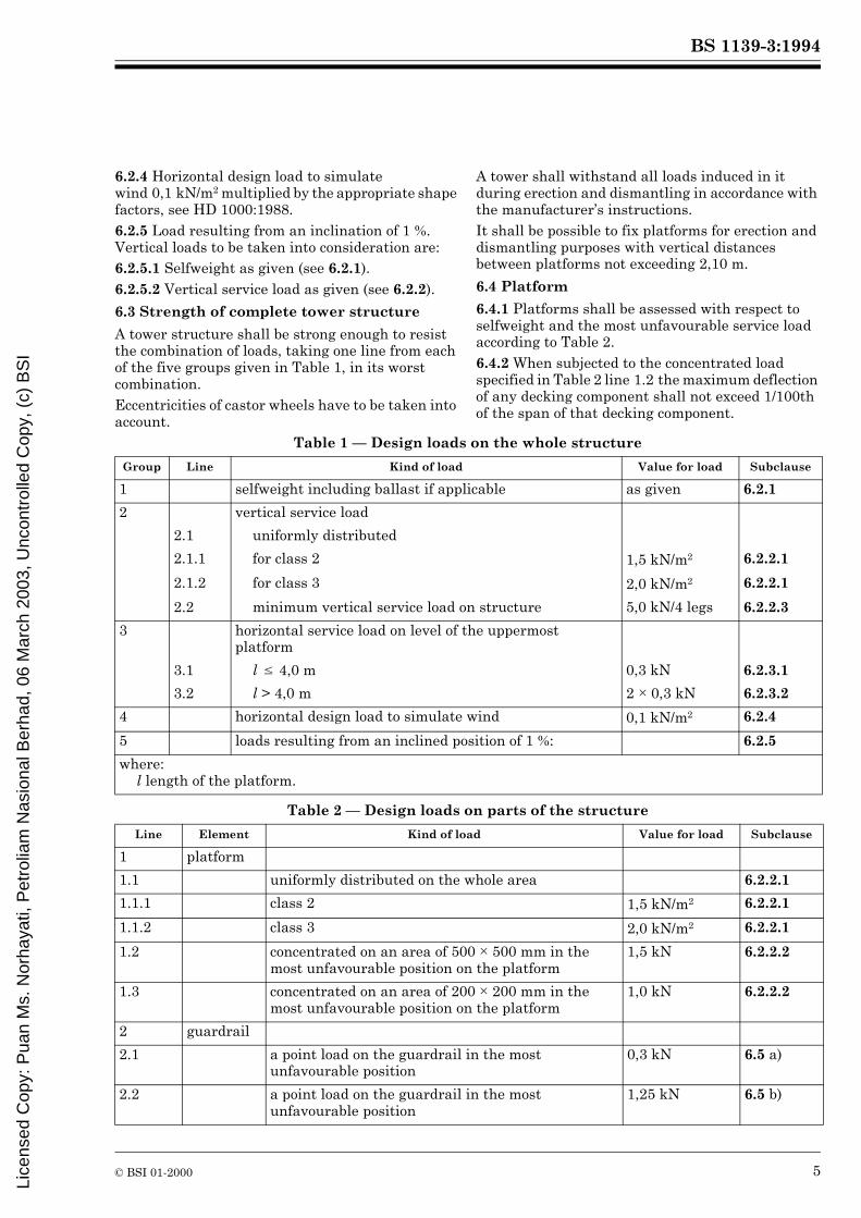
Table 1 — Design loads on the whole structure
Table 2 — Design loads on parts of the structure
Group Line Kind of load Value for load Subclause
1 selfweight including ballast if applicable as given 6.2.1
2 vertical service load
2.1 uniformly distributed
2.1.1 for class 2 1,5 kN/m2 6.2.2.1
2.1.2 for class 3 2,0 kN/m2 6.2.2.1
2.2 minimum vertical service load on structure 5,0 kN/4 legs 6.2.2.3
3 horizontal service load on level of the uppermost platform
3.1 l k 4,0 m 0,3 kN 6.2.3.1
3.2 l > 4,0 m 2 × 0,3 kN 6.2.3.2
4 horizontal design load to simulate wind 0,1 kN/m2 6.2.4
5 loads resulting from an inclined position of 1 %: 6.2.5
where:l length of the platform.
Line Element Kind of load Value for load Subclause
1 platform
1.1 uniformly distributed on the whole area 6.2.2.1
1.1.1 class 2 1,5 kN/m2 6.2.2.1
1.1.2 class 3 2,0 kN/m2 6.2.2.1
1.2 concentrated on an area of 500 × 500 mm in the most unfavourable position on the platform
1,5 kN 6.2.2.2
1.3 concentrated on an area of 200 × 200 mm in the most unfavourable position on the platform
1,0 kN 6.2.2.2
2 guardrail
2.1 a point load on the guardrail in the most unfavourable position
0,3 kN 6.5 a)
2.2 a point load on the guardrail in the most unfavourable position
1,25 kN 6.5 b)
Lice
nsed
Cop
y: P
uan
Ms.
Nor
haya
ti, P
etro
liam
Nas
iona
l Ber
had,
06
Mar
ch 2
003,
Unc
ontr
olle
d C
opy,
(c)
BS
I
BS 1139-3:1994
6 © BSI 01-2000
In addition, in the case of decking components with spans of 2 m or greater, the maximum deflection difference of loaded and unloaded decking components shall not exceed 20 mm.
6.5 Guardrails
A guardrail, regardless of its span, shall withstand separately (see Table 2):
a) a point load of 0,3 kN with an elastic deflection of not more than 35 mm; andb) a point load of 1,25 kN without breaking or disconnecting and without being displaced from its original line by more than 200 mm at any point.
Both the above loads shall be applied in the most unfavourable positions and at any horizontal or downward angle.
6.6 Lateral movement
The base of the tower shall be stiff in the horizontal plane to allow relocation. This shall include outriggers and stabilizers where appropriate.
7 Components7.1 Castor wheels
7.1.1 General
Castor wheels shall be fixed to the tower in such a way that they cannot be accidentally detached.
7.1.2 Brakes
All castors shall have wheel brakes. They shall have swivel brakes unless by their design they are not eccentric when locked.The brake mechanism shall be designed in such a way that it can only be unlocked by a deliberate action. The brake mechanism must effectively prevent any rotation of the wheel when a horizontal force of 0,30 kN is applied through the vertical swivel axis of the castor as close as possible above the castor housing and in the rolling direction of the castor. The full value of the specified service load is to be taken into account when testing the castor brakes.
7.1.3 Design load
The maximum design load of castors given by the manufacturer shall be verified by a minimum of 5 control tests.The test load shall be 3 times the maximum design load derived from Table 1. One line is taken from each of the five groups in Table 1 to establish the maximum design load.The brakes being locked, an initial vertical load of 0,50 kN is to be applied, the plate of the fork being taken as the origin for measurements of vertical displacement dc.
The load shall be increased and the vertical deformation dc shall be measured. The load shall be returned to 0,50 kN. After 30 min the residual deformation dr shall be measured.The control test shall meet both of the following requirements:
— residual deformation after 30 min shall not be more than 1,5 mm;— total deformation dr not more than 15 mm.
The maximum design load is verified if all 5 control tests meet the test requirements.
7.1.4 Wheels
Wheels shall be of punctureless type and suitable for their designed use.
7.2 Means for stabilizing
7.2.1 Stabilizers and outriggers
The stabilizers and outriggers of a tower shall be designed as integral parts of the main structure and shall provide means of adjustment to ensure contact with the ground.The method of fixing the stabilizer or outrigger to the tower shall have adequate strength and shall be such that the loads in the stabilizer or outrigger are transferred to the tower without slip, rotation or other movement of the stabilizer or outrigger.
7.2.2 Ballast
If ballast is necessary it shall be securely positioned and made of rigid materials such as steel or concrete, but excluding liquids or granular materials.
7.3 Connections
7.3.1 General
Connection between separate parts shall be effective and easy to monitor. They shall be easy to assemble and secure against accidental disconnection.
7.3.2 Vertical spigot and socket connection
When assembled, the horizontal movement (slack or play) between upper and lower components shall not exceed 4 mm or a movement away from the centre line of 2 mm.In all cases it shall not be possible to disconnect an upper component laterally until the upper component has been lifted more than 80 mm.When the spigot and socket connection acts over a distance less than 150 mm the connection shall be provided with a positive locking device, such as a cross pin, to prevent the upper component from being lifted unintentionally:NOTE The captive locking device shall be placed in such a way that its positive action can be monitored visually.
Lice
nsed
Cop
y: P
uan
Ms.
Nor
haya
ti, P
etro
liam
Nas
iona
l Ber
had,
06
Mar
ch 2
003,
Unc
ontr
olle
d C
opy,
(c)
BS
I
BS 1139-3:1994
© BSI 01-2000 7
7.3.3 Other vertical connections
There shall be equivalent provisions related to 7.3.2 to limit the risk of accidental disconnections.NOTE Other strength requirements of this Harmonization Document may impose further limitations on the arrangement of connections.
7.3.4 Assessment of joints and connections
The strength of joints and connections (e.g. welded joints, compressed connections, hollow type rivet connections) shall be verified by calculation or by test.In the latter case three tests shall be carried out on each type of joint in each of which it shall be verified that the joint is capable of withstanding without collapse three times the greatest working stress in the components.
7.4 Access to platforms
7.4.1 General requirements
Access to the platforms in an assembled tower shall be provided by a stairway, a stairladder or an inclined or vertical ladder contained within the main structural supports. They shall:
— be secured against unintentional loosening;— not rest on the ground;— have a distance from the ground to the first step or rung of 400 mm maximum (if the first step is a platform, 600 mm may be allowable);— have steps/rungs with constant spacing and a slip resistant surface.
From the front edge of the step or from the centre of the rung to any obstacle behind the stairway/ladder there shall be a horizontal distance of s = 150 mm minimum (s given in Figure 3).The minimum clear height for access measured between the steps or rungs and the supporting structure of the platform above shall not be less than 1,75 m.Access to a working platform through an aperture in a platform shall be provided with means to prevent falling through.The aperture shall be as small as practicable, but it shall have a minimum clear opening of:
0,40 m wide × 0,60 m long.
7.4.2 Stairway and stairladder requirements
Stairways and stairladders are means of access to working platforms, which enable persons to ascend and descend facing forwards.
The outside of stair flights shall be provided with a handrail which runs approximately parallel to the stairs. Where a flight of stairs is provided in a continuous dog-leg style, a handrail shall be also provided on the inside. Where there are flights of stairs interrupted by platforms at k 2 m intervals the inside handrail may be omitted.Flights of stairs in a continuous dog-leg style shall have landings. Each of these stairs shall have a minimum of one landing and this shall have a minimum length of 300 mm.
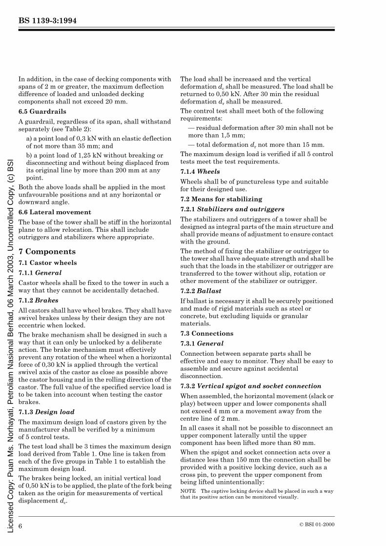
7.4.2.1 Stairway requirements (see Figure 1)
— Inclination 35° k a k 55°.— Vertical step rise t = 190 mm minimum to 250 mm maximum.— Minimum step depth d = 125 mm.— Minimum clear width 400 mm.— Horizontal gap between steps 0 k g k 50 mm.
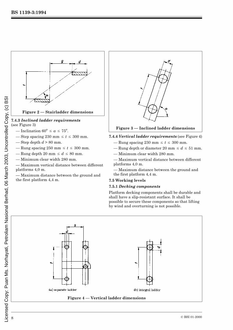
7.4.2.2 Stairladder requirements (see Figure 2)
— Inclination 35° k a k 55°.— Vertical step rise t = 150 mm minimum to 250 mm maximum.— Minimum step depth d = 80 mm.— Minimum clear width 280 mm.— Horizontal gap between steps 0 k g k 200 mm.
Figure 1 — Stairway dimensions
Lice
nsed
Cop
y: P
uan
Ms.
Nor
haya
ti, P
etro
liam
Nas
iona
l Ber
had,
06
Mar
ch 2
003,
Unc
ontr
olle
d C
opy,
(c)
BS
I
BS 1139-3:1994
8 © BSI 01-2000
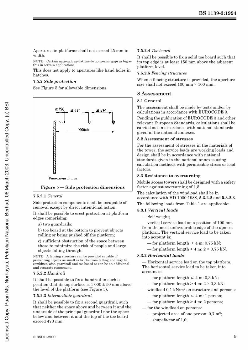
7.4.3 Inclined ladder requirements (see Figure 3)
— Inclination 60° k a k 75°.— Step spacing 230 mm k t k 300 mm.— Step depth d > 80 mm.— Rung spacing 250 mm k t k 300 mm.— Rung depth 20 mm k d k 80 mm.— Minimum clear width 280 mm.— Maximum vertical distance between different platforms 4,0 m.— Maximum distance between the ground and the first platform 4,4 m.
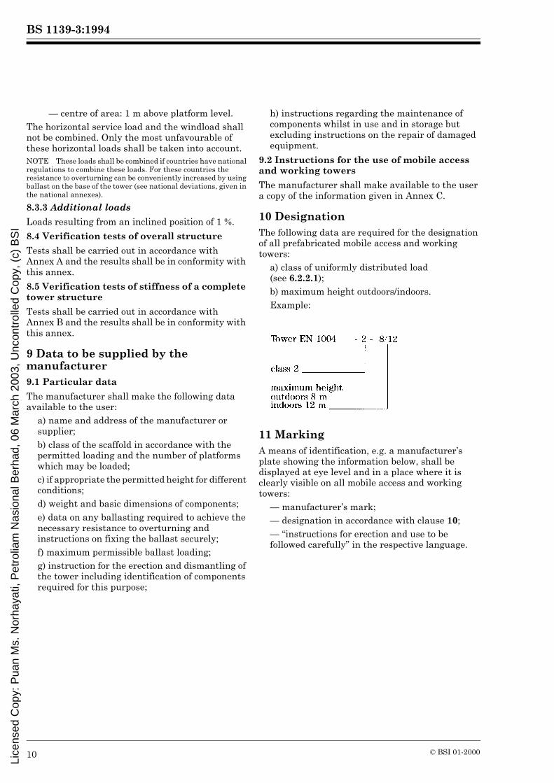
7.4.4 Vertical ladder requirements (see Figure 4)
— Rung spacing 230 mm k t k 300 mm.— Rung depth or diameter 20 mm k d k 51 mm.— Minimum clear width 280 mm.— Maximum vertical distance between different platforms 4,0 m.— Maximum distance between the ground and the first platform 4,4 m.
7.5 Working levels
7.5.1 Decking components
Platform decking components shall be durable and shall have a slip-resistant surface. It shall be possible to secure these components so that lifting by wind and overturning is not possible.
Figure 2 — Stairladder dimensions
Figure 3 — Inclined ladder dimensions
Figure 4 — Vertical ladder dimensions
Lice
nsed
Cop
y: P
uan
Ms.
Nor
haya
ti, P
etro
liam
Nas
iona
l Ber
had,
06
Mar
ch 2
003,
Unc
ontr
olle
d C
opy,
(c)
BS
I
BS 1139-3:1994
© BSI 01-2000 9
Apertures in platforms shall not exceed 25 mm in width.NOTE Certain national regulations do not permit gaps as big as this in certain applications.
This does not apply to apertures like hand holes in hatches.
7.5.2 Side protection
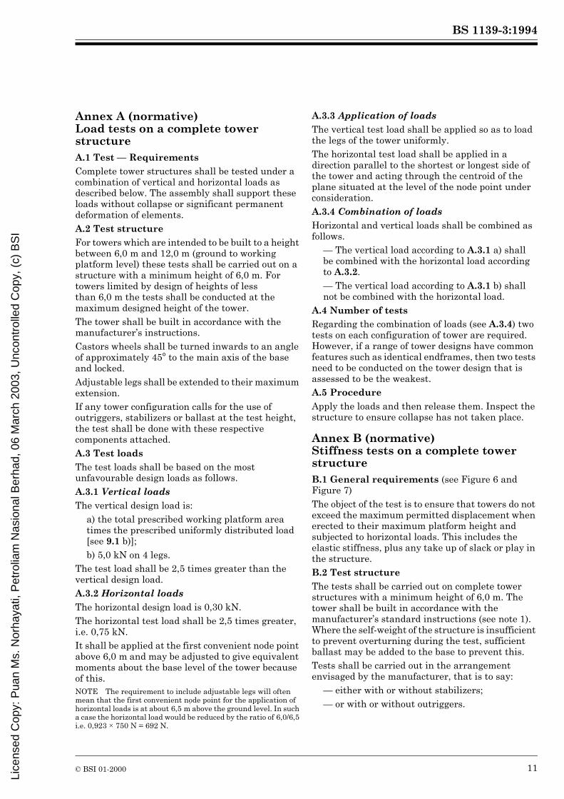
See Figure 5 for allowable dimensions.
7.5.2.1 General
Side protection components shall be incapable of removal except by direct intentional action.It shall be possible to erect protection at platform edges comprising:
a) two guardrails;b) toe board at the bottom to prevent objects rolling or being pushed off the platform;c) sufficient obstruction of the space between these to minimize the risk of people and large objects falling through.
NOTE A fencing structure can be provided capable of preventing objects as small as bricks from falling and may be combined with guardrail and toe board or can be an additional and separate component.
7.5.2.2 Handrail
It shall be possible to fix a handrail in such a position that its top surface is 1 000 ± 50 mm above the level of the platform (see Figure 5).
7.5.2.3 Intermediate guardrail
It shall be possible to fix a second guardrail, such that neither the space above and between it and the underside of the principal guardrail nor the space below and between it and the top of the toe board exceed 470 mm.
7.5.2.4 Toe board
It shall be possible to fix a solid toe board such that its top edge is at least 150 mm above the adjacent platform level.
7.5.2.5 Fencing structures
When a fencing structure is provided, the aperture size shall not exceed 100 mm × 100 mm.
8 Assessment8.1 General
The assessment shall be made by tests and/or by calculations in accordance with EUROCODE 3.Pending the publication of EUROCODE 3 and other relevant European Standards, calculations shall be carried out in accordance with national standards given in the national annexes.
8.2 Assessment of stresses
For the assessment of stresses in the materials of the tower, the service loads are working loads and design shall be in accordance with national standards given in the national annexes using calculation methods with permissible stress or load factors.
8.3 Resistance to overturning
Mobile access towers shall be designed with a safety factor against overturning of 1,5.The calculation of the windload shall be in accordance with HD 1000:1988, 5.3.2.2 and 5.3.2.3.The following loads from Table 1 are applicable:
8.3.1 Vertical loads
— Self weight;— vertical service load on a position of 100 mm from the most unfavourable edge of the upmost platform. The vertical service load to be taken into account is:
— for platform length k 4 m: 0,75 kN;— for platform length > 4 m: 2 × 0,75 kN.
8.3.2 Horizontal loads
— Horizontal service load on the top platform. The horizontal service load to be taken into account is:
— for platform length k 4 m: 0,3 kN;— for platform length > 4 m: 2 × 0,3 kN;
— windload 0,1 kN/m2 on structure and persons:— for platform length k 4 m: 1 person;— for platform length > 4 m: 2 persons;
— for the windload on persons:— projected area of one person: 0,7 m2;— shapefactor of 1,0;
Figure 5 — Side protection dimensions
Lice
nsed
Cop
y: P
uan
Ms.
Nor
haya
ti, P
etro
liam
Nas
iona
l Ber
had,
06
Mar
ch 2
003,
Unc
ontr
olle
d C
opy,
(c)
BS
I
BS 1139-3:1994
10 © BSI 01-2000
— centre of area: 1 m above platform level.The horizontal service load and the windload shall not be combined. Only the most unfavourable of these horizontal loads shall be taken into account.NOTE These loads shall be combined if countries have national regulations to combine these loads. For these countries the resistance to overturning can be conveniently increased by using ballast on the base of the tower (see national deviations, given in the national annexes).
8.3.3 Additional loads
Loads resulting from an inclined position of 1 %.
8.4 Verification tests of overall structure
Tests shall be carried out in accordance with Annex A and the results shall be in conformity with this annex.
8.5 Verification tests of stiffness of a complete tower structure
Tests shall be carried out in accordance with Annex B and the results shall be in conformity with this annex.
9 Data to be supplied by the manufacturer9.1 Particular data
The manufacturer shall make the following data available to the user:
a) name and address of the manufacturer or supplier;b) class of the scaffold in accordance with the permitted loading and the number of platforms which may be loaded;c) if appropriate the permitted height for different conditions;d) weight and basic dimensions of components;e) data on any ballasting required to achieve the necessary resistance to overturning and instructions on fixing the ballast securely;f) maximum permissible ballast loading;g) instruction for the erection and dismantling of the tower including identification of components required for this purpose;
h) instructions regarding the maintenance of components whilst in use and in storage but excluding instructions on the repair of damaged equipment.
9.2 Instructions for the use of mobile access and working towers
The manufacturer shall make available to the user a copy of the information given in Annex C.
10 DesignationThe following data are required for the designation of all prefabricated mobile access and working towers:
a) class of uniformly distributed load (see 6.2.2.1);b) maximum height outdoors/indoors.Example:
11 MarkingA means of identification, e.g. a manufacturer’s plate showing the information below, shall be displayed at eye level and in a place where it is clearly visible on all mobile access and working towers:
— manufacturer’s mark;— designation in accordance with clause 10;— “instructions for erection and use to be followed carefully” in the respective language.
Lice
nsed
Cop
y: P
uan
Ms.
Nor
haya
ti, P
etro
liam
Nas
iona
l Ber
had,
06
Mar
ch 2
003,
Unc
ontr
olle
d C
opy,
(c)
BS
I
BS 1139-3:1994
© BSI 01-2000 11
Annex A (normative) Load tests on a complete tower structureA.1 Test — RequirementsComplete tower structures shall be tested under a combination of vertical and horizontal loads as described below. The assembly shall support these loads without collapse or significant permanent deformation of elements.A.2 Test structureFor towers which are intended to be built to a height between 6,0 m and 12,0 m (ground to working platform level) these tests shall be carried out on a structure with a minimum height of 6,0 m. For towers limited by design of heights of less than 6,0 m the tests shall be conducted at the maximum designed height of the tower.The tower shall be built in accordance with the manufacturer’s instructions.Castors wheels shall be turned inwards to an angle of approximately 45° to the main axis of the base and locked.Adjustable legs shall be extended to their maximum extension.If any tower configuration calls for the use of outriggers, stabilizers or ballast at the test height, the test shall be done with these respective components attached.A.3 Test loadsThe test loads shall be based on the most unfavourable design loads as follows.A.3.1 Vertical loadsThe vertical design load is:
a) the total prescribed working platform area times the prescribed uniformly distributed load [see 9.1 b)];b) 5,0 kN on 4 legs.
The test load shall be 2,5 times greater than the vertical design load.A.3.2 Horizontal loadsThe horizontal design load is 0,30 kN.The horizontal test load shall be 2,5 times greater, i.e. 0,75 kN.It shall be applied at the first convenient node point above 6,0 m and may be adjusted to give equivalent moments about the base level of the tower because of this.NOTE The requirement to include adjustable legs will often mean that the first convenient node point for the application of horizontal loads is at about 6,5 m above the ground level. In such a case the horizontal load would be reduced by the ratio of 6,0/6,5 i.e. 0,923 × 750 N = 692 N.
A.3.3 Application of loadsThe vertical test load shall be applied so as to load the legs of the tower uniformly.The horizontal test load shall be applied in a direction parallel to the shortest or longest side of the tower and acting through the centroid of the plane situated at the level of the node point under consideration.A.3.4 Combination of loadsHorizontal and vertical loads shall be combined as follows.
— The vertical load according to A.3.1 a) shall be combined with the horizontal load according to A.3.2.— The vertical load according to A.3.1 b) shall not be combined with the horizontal load.
A.4 Number of testsRegarding the combination of loads (see A.3.4) two tests on each configuration of tower are required. However, if a range of tower designs have common features such as identical endframes, then two tests need to be conducted on the tower design that is assessed to be the weakest.A.5 ProcedureApply the loads and then release them. Inspect the structure to ensure collapse has not taken place.
Annex B (normative) Stiffness tests on a complete tower structureB.1 General requirements (see Figure 6 and Figure 7)The object of the test is to ensure that towers do not exceed the maximum permitted displacement when erected to their maximum platform height and subjected to horizontal loads. This includes the elastic stiffness, plus any take up of slack or play in the structure.B.2 Test structureThe tests shall be carried out on complete tower structures with a minimum height of 6,0 m. The tower shall be built in accordance with the manufacturer’s standard instructions (see note 1). Where the self-weight of the structure is insufficient to prevent overturning during the test, sufficient ballast may be added to the base to prevent this.Tests shall be carried out in the arrangement envisaged by the manufacturer, that is to say:
— either with or without stabilizers;— or with or without outriggers.
Lice
nsed
Cop
y: P
uan
Ms.
Nor
haya
ti, P
etro
liam
Nas
iona
l Ber
had,
06
Mar
ch 2
003,
Unc
ontr
olle
d C
opy,
(c)
BS
I

BS 1139-3:1994
12 © BSI 01-2000
As the stiffness of the tower is not affected by ballast only one test is necessary, where ballast is the only means of stability.Adjustable legs, if fitted, shall be extended to 50 % of their maximum extension (see note 2). Castor wheels shall be turned in their most unfavourable orientation and shall be locked.NOTE 1 If the maximum platform height, in accordance with the manufacturer’s instructions, is less than 6,0 m the test structure shall be erected to at least 6,0 m height with additional components as prescribed by the manufacturer. This extra height will enable D1 to be measured. The stiffness should not be adversely affected.NOTE 2 As adjustable legs are normally fitted to level the tower, this represents a working condition.
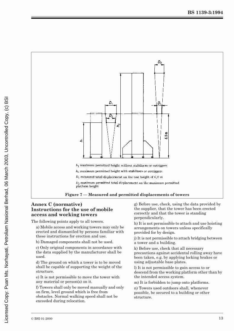
B.3 Method of testThe horizontal test load shall be 500 N.It shall be applied at the first convenient node point above 6,0 m level. It may be adjusted to give equivalent moment above the base level of the tower because of this (see annex A.3).The load shall be applied perpendicular to one face of the tower and acting through the centroid. The load shall be applied in one direction and then the opposite direction, and the total displacement D1 (in mm) shall be measured at the exact height of 6,0 m (see Figure 6).This test is repeated at 90° to the first face (see Figure 6).B.4 Result of test (see Figure 7)The total displacement measured as described in the above test shall be correlated by linear calculation to give a value of displacement D2 for the maximum permitted platform height of the tower, with or without stabilizers, outriggers or ballast. This total displacement D2 shall not exceed 200 mm and may limit the maximum platform height.The maximum height of platform, limited by stiffness, is given by:
NOTE The measured value D1, enables the limit of height to be calculated.For example:
a) If the measured value D1 is 100 mm, then from the formula
the maximum platform height h1 = 12 m.b) If the measured value D1 is 300 mm, then the maximum permitted platform height h1 = 4 m.The linear formula is not precisely correct but over the range of towers that this Harmonization Document covers, calculations and practical tests have shown that a linear relationship is acceptable.
NOTE 1 First test in two opposite directions.NOTE 2 Second test in two opposite directions.
Figure 6 — Horizontal loads for stiffness tests on a complete tower structure
Lice
nsed
Cop
y: P
uan
Ms.
Nor
haya
ti, P
etro
liam
Nas
iona
l Ber
had,
06
Mar
ch 2
003,
Unc
ontr
olle
d C
opy,
(c)
BS
I
BS 1139-3:1994
© BSI 01-2000 13
Annex C (normative) Instructions for the use of mobile access and working towersThe following points apply to all towers.
a) Mobile access and working towers may only be erected and dismantled by persons familiar with these instructions for erection and use.b) Damaged components shall not be used.c) Only original components in accordance with the data supplied by the manufacturer shall be used.d) The ground on which a tower is to be moved shall be capable of supporting the weight of the structure.e) It is not permissible to move the tower with any material or person(s) on it.f) Towers shall only be moved manually and only on firm, level ground which is free from obstacles. Normal walking speed shall not be exceeded during relocation.
g) Before use, check, using the data provided by the supplier, that the tower has been erected correctly and that the tower is standing perpendicularly.h) It is not permissible to attach and use hoisting arrangements on towers unless specifically provided for by design.j) It is not permissible to attach bridging between a tower and a building.k) Before use, check that all necessary precautions against accidental rolling away have been taken, e.g. by applying locking brakes or using adjustable base plates.l) It is not permissible to gain access to or descend from the working platform other than by the intended access system.m) It is forbidden to jump onto platforms.n) Towers used outdoors shall, whenever possible, be secured to a building or other structure.
Figure 7 — Measured and permitted displacements of towers
Lice
nsed
Cop
y: P
uan
Ms.
Nor
haya
ti, P
etro
liam
Nas
iona
l Ber
had,
06
Mar
ch 2
003,
Unc
ontr
olle
d C
opy,
(c)
BS
I
BS 1139-3:1994
14 © BSI 01-2000
National annex NA (informative) Cross-references
National annex NB (normative) Publications applicable to the use of this standard in the UKBS 4, Structural steel sections. BS 449, Specification for the use of structural steel in building. BS 729, Specification for hot dip galvanized coatings on iron and steel articles. BS 916, Specification for black bolts, screws and nuts, hexagon and square, with B.S.W. threads, and partly machined bolts, screws and nuts, hexagon and square, with B.S.W. or B.S.F. threads. BS 970, Specification for wrought steels for mechanical and allied engineering purposes. BS 1129, Specification for portable timber ladders, steps, trestles and lightweight stagings. BS 1139, Metal scaffolding. BS 1139-1, Tubes. BS 1139-1.1, Specification for steel tube. BS 1139-1.2, Specification for aluminium tube. BS 1139-2, Couplers. BS 1139-2.1, Specification for steel couplers, loose spigots and base-plates for use in working scaffolds and falsework made of steel tubes. (Identical with EN 74)BS 1139-2.2, Specification for steel and aluminium couplers, fittings and accessories for use in tubular scaffolding. BS 1139-3, Specification for prefabricated access and working towers. BS 1139-4, Specification for prefabricated steel splitheads and trestles. BS 1139-5, Specification for materials, dimensions, design loads and safety requirements for service and working scaffolds made of prefabricated elements. (Identical with HD 1000)BS 1140, Specification for resistance spot welding of uncoated and coated low carbon steel. BS 1449, Steel plate, sheet and strip. BS 1452, Specification for flake graphite cast iron. BS 1470, Specification for wrought aluminium and aluminium alloys for general engineering purposes: plate, sheet and strip. BS 1471, Specification for wrought aluminium and aluminium alloys for general engineering purposes — drawn tube. BS 1472, Specification for wrought aluminium and aluminium alloys for general engineering purposes — forging stock and forgings. BS 1473, Specification for wrought aluminium and aluminium alloys for general engineering purposes — rivet, bolt and screw stock. BS 1474, Specification for wrought aluminium and aluminium alloys for general engineering purposes: bars, extruded round tubes and sections. BS 1490, Specification for aluminium and aluminium alloy ingots and castings for general engineering purposes. BS 2037, Specification for portable aluminium ladders, steps, trestles and lightweight stagings. BS 2901, Filler rods and wires for gas-shielded arc welding.
Publication referred to Corresponding British Standard
HD 1000:1988 BS 1139 Metal scaffoldingPart 5:1990 Specification for materials, dimensions, design loads and safety requirements for service and working scaffolds made of prefabricated elements
Lice
nsed
Cop
y: P
uan
Ms.
Nor
haya
ti, P
etro
liam
Nas
iona
l Ber
had,
06
Mar
ch 2
003,
Unc
ontr
olle
d C
opy,
(c)
BS
I
BS 1139-3:1994
© BSI 01-2000 15
BS 2994, Specification for cold rolled steel sections. BS 3019, TIG welding. BS 3019-1, Specification for TIG welding of aluminium, magnesium and their alloys. BS 3100, Specification for steel castings for general engineering purposes. BS 3436, Specification for ingot zinc. BS 3468, Specification for austenitic cast iron. BS 3571, MIG welding. BS 3571-1, Specification for MIG welding of aluminium and aluminium alloys. BS 4114, Specification for dimensional and quantity tolerances for steel drop and press forgings and for upset forgings made on horizontal forging machines. BS 4300, Wrought aluminium and aluminium alloys for general engineering purposes (supplementary series). BS 4300-1, Aluminium alloy longitudinally welded tube. BS 4360, Specification for weldable structural steels. BS 4848, Hot-rolled structural steel sections. BS 4848-2, Specification for hot-finished hollow sections. BS 4848-4, Equal and unequal angles. BS 4848-5, Bulb flats. BS 5135, Specification for arc welding of carbon and carbon manganese steels. BS 5268, Structural use of timber. BS 5493, Code of practice for protective coating of iron and steel structures against corrosion. BS 5973, Code of practice for access and working scaffolds and special scaffold structures in steel. BS 5974, Code of practice for temporarily installed suspended scaffolds and access equipment. BS 6323, Specification for seamless and welded steel tubes for automobile, mechanical and general engineering purposes. BS 6399, Loading for bearings. BS 6399-1, Code of practice for dead and imposed loads. BS 6681, Specification for malleable cast iron. BS EN 10002, Tensile testing of metallic materials. BS EN 10002-1, Method of test at ambient temperature3). CP 3, Code of basic data for the design of buildings. CP 3:Chapter V, Loading. CP 3:Chapter V-2, Wind loads. CP 118, The structural use of aluminium. PD 6484, Commentary on corrosion at bimetallic contacts and its alleviation. Other publicationsOperators code of practice, published by the Prefabricated Aluminium Scaffolding Manufacturer’s Association Limited.NOTE Under national deviations for the UK, HD 1004:1992, the following standards were listed which have since been withdrawn.
BS 18, Method for tensile testing of metals (including aerospace materials). DD 24, Recommendations for methods of protection against corrosion on light section steel used in building. DD 72, Design requirements for access and working scaffolds.
3) Supersedes BS 18.
Lice
nsed
Cop
y: P
uan
Ms.
Nor
haya
ti, P
etro
liam
Nas
iona
l Ber
had,
06
Mar
ch 2
003,
Unc
ontr
olle
d C
opy,
(c)
BS
I
BS 1139-3:1994
BSI389 Chiswick High RoadLondonW4 4AL
BSI — British Standards InstitutionBSI is the independent national body responsible for preparing British Standards. It presents the UK view on standards in Europe and at the international level. It is incorporated by Royal Charter.
Revisions
British Standards are updated by amendment or revision. Users of British Standards should make sure that they possess the latest amendments or editions.
It is the constant aim of BSI to improve the quality of our products and services. We would be grateful if anyone finding an inaccuracy or ambiguity while using this British Standard would inform the Secretary of the technical committee responsible, the identity of which can be found on the inside front cover. Tel: 020 8996 9000. Fax: 020 8996 7400.
BSI offers members an individual updating service called PLUS which ensures that subscribers automatically receive the latest editions of standards.
Buying standards
Orders for all BSI, international and foreign standards publications should be addressed to Customer Services. Tel: 020 8996 9001. Fax: 020 8996 7001.
In response to orders for international standards, it is BSI policy to supply the BSI implementation of those that have been published as British Standards, unless otherwise requested.
Information on standards
BSI provides a wide range of information on national, European and international standards through its Library and its Technical Help to Exporters Service. Various BSI electronic information services are also available which give details on all its products and services. Contact the Information Centre. Tel: 020 8996 7111. Fax: 020 8996 7048.
Subscribing members of BSI are kept up to date with standards developments and receive substantial discounts on the purchase price of standards. For details of these and other benefits contact Membership Administration. Tel: 020 8996 7002. Fax: 020 8996 7001.
Copyright
Copyright subsists in all BSI publications. BSI also holds the copyright, in the UK, of the publications of the international standardization bodies. Except as permitted under the Copyright, Designs and Patents Act 1988 no extract may be reproduced, stored in a retrieval system or transmitted in any form or by any means – electronic, photocopying, recording or otherwise – without prior written permission from BSI.
This does not preclude the free use, in the course of implementing the standard, of necessary details such as symbols, and size, type or grade designations. If these details are to be used for any other purpose than implementation then the prior written permission of BSI must be obtained.
If permission is granted, the terms may include royalty payments or a licensing agreement. Details and advice can be obtained from the Copyright Manager. Tel: 020 8996 7070.
Lice
nsed
Cop
y: P
uan
Ms.
Nor
haya
ti, P
etro
liam
Nas
iona
l Ber
had,
06
Mar
ch 2
003,
Unc
ontr
olle
d C
opy,
(c)
BS
I


