30
Copyright 2011 Reuland All Rights Reserved REULAND PARTIAL MOTORS Stator and Rotor Sets

Copyright 2011 Reuland All Rights Reserved
REULANDPARTIAL MOTORS
Stator and Rotor Sets
Reuland www.reuland.com 17969 E. Railroad St. – Industry, CA 91749 Phone: (626) 854-7440 Email: [email protected]
REULAND PARTIAL MOTORS
Stator & Rotor Sets
MECHANICAL FEATURES
• All Reuland Partial Motors are available as stator and rotor sets or as individual
components.
• Vast selection of diameters and core lengths are available as standard. Special lengths are available upon request.
• High pressure die cast aluminum rotors include cooling fins and balancing lugs. Cooling fins and balancing lugs are removed on high speed applications. Fabricated rotors and encapsulated end rings are available for special performance characteristics.
• Large straight bore rotors are available with oversized diameters or tapered bore upon request and keyways where required.
• Maximum bore shown is for die cast rotors without keyway. Fabricated rotors generally allow for larger bores.
• Shell type motors may be furnished with standard length or extended length shells made from cold roll or stainless steel. Shells are also available with heavy wall thickness and grooved for customer liquid cooling.
• High temperature, oil resistant, three foot leads are standard.
• Solid magnetic shaft material is generally required for large rotor bores and maximum horsepower designs.
ELECTRICAL FEATURES
• 0.02 to 1100 horsepower, maximum performance designs, depending on speed and
cooling.
• Vast selection of frame sizes available for three enclosure types: Liquid Cooled (TELC), Fan Cooled (TEFC), Non Vented (TENV).
• 2 through 6 poles available as standard, higher upon request. Multi-speed also available.
• Consult factory regarding extremely low speed applications.
• Squirrel cage induction, NEMA design B and inverter duty is standard.
• Stator windings for up to 600 volts are standard.
• High silicon electrical steel, fully insulated, to reduce core losses, allow standard
designs to operate up to 120 hertz. Special low loss laminations with minimum core
loss are available for high frequency applications to 3000 hertz.
• Premium class H insulation system with high temperature polyester varnish is standard.
• Customer is responsible for cooling partial motors.
Release: Jan 2012
2

Reuland www.reuland.com 17969 E. Railroad St. – Industry, CA 91749 Phone: (626) 854-7440 Email: [email protected]
REULAND PARTIAL MOTORS
Stator & Rotor Sets
IMPORTANT CONSIDERATIONS
• Selection of 2, 4 or 6 pole stator and rotor sets generally depends on the application
requirement. The 2 pole version offers higher speed capabilities compared to 4 pole and 6 pole versions. The 4 pole version offers highest power density in smallest package with large rotor bore. The 6 pole version offers higher torque at low speed and allows for even larger rotor bore.
• For uniform air gap and optimum balance, rotor diameters can be furnished rough for customer to finish turn and balance after the rotor is installed on the shaft.
• Maximum speeds shown are limited by the centrifugal forces acting on the rotor and are based upon the standard rotor bore. An oversize bore or deep keyway may reduce these values. High speed rotor/shaft combinations should have balancing rings in order to allow for the delicate trim balance required.
• Stator and rotor sets are identified with their model or serial number, along with a stamped loose nameplate.
• A certified dimension drawing is available for each motor. Always review these dimensions or call the factory before releasing order to production on new designs.
• The power tables list the power capabilities of stator and rotor sets at various speeds for three enclosure types (TELC, TEFC and TENV). The sets are listed by frame size which is representative of the stator outside diameter and core length.
Release: Jan 2012
3

60 100 200 300 400 500 600 700 800 900 Max. speed
3600 6000 12000 18000 24000 30000 36000 42000 48000 54000 (r/min)
(F) - (BM)
315 - 0.98 0.1 0.28 0.75 1.2 1.6 2 2.4 2.8 3.2 3.6
315 - 2.17 0.35 0.8 1.8 2.7 3.6 4.5 5.4 6.3 7.2 8.1
315 - 3.15 0.65 1.25 2.7 4.1 5.4 6.8 8.1 9.5 11 12
315 - 3.94 0.85 1.6 3.5 5.3 7 8.7 10.5 12 14 15.5
354 - 1.77 0.4 1 2.2 3.3 4.4 5.5 6.6 7.7 8.8
354 - 2.36 0.7 1.4 3 4.5 6 7.5 9 10.5 12
354 - 3.15 1 1.9 4 6 8 10 12 14 16
354 - 3.94 1.3 2.4 5.1 7.7 10.2 13 15.5 18 20.5
419 - 1.77 0.6 1.4 3.8 5.7 7.6 9.2 10
419 - 2.56 1 2.3 5.7 8.4 11 13.5 15
419 - 3.15 1.4 3.2 7.2 10.6 14 17 19
419 - 3.94 1.9 4.3 9.2 13 17.5 21 23.5
419 - 4.72 2.3 5.2 11 16 21 25.5 28.5
472 - 1.50 0.8 1.8 4.7 7.4 9.4 11 12.5
472 - 2.25 1.5 3.3 7.5 11 14 16.5 18.5
472 - 3.00 2.3 4.7 10 14.5 18.5 21.5 24
472 - 3.75 3.2 6.2 12.5 18 23 27 30
472 - 4.75 4.3 7.8 16 23 29 34 38
472 - 5.75 5.4 9.5 19 28 35 41 46
472 - 6.75 6.5 11 22 33 42 49 55
472 - 7.75 7.5 12.5 25 38 48 56 62
532 - 1.50 0.93 2 5 7.5 9.5 11
532 - 2.00 1.5 3.1 7.3 11 14 16.5
532 - 2.75 2.4 4.8 11 16.5 21 24.5
532 - 4.25 4.2 8.3 17.5 26 33 38
532 - 5.75 6.3 12 24 36 45 52
532 - 7.25 8 15 30 45 57 66
622 - 2.00 2.7 4.8 10.1 15.5 20
622 - 2.75 3.8 6.8 14.5 23 29.5
622 - 3.87 5.5 10.5 21.5 32 41
622 - 4.25 6.4 12 23.5 35 45
622 - 5.75 9.4 16 32 48 62
622 - 7.25 12 20 40 61 78
622 - 10.75 18 30 60 90 115
782 - 1.69 4.2 7 14 21
782 - 2.44 6.3 10.5 21.5 32
782 - 2.94 7.8 13 26 39
782 - 3.94 10.5 17.5 35 53
782 - 5.44 15 24.5 49 74
782 - 6.94 19 31 63 95
782 - 7.94 21.5 36 72 108
782 - 8.94 24 40 81 122
782 - 9.94 27 45 90 135
782 - 10.94 30 50 100 150
945 - 2.94 11.5 22 40 50
945 - 3.44 15.5 26 47 58
945 - 4.69 21 35 64 79
945 - 5.94 27 45 81 100
945 - 7.94 36 60 108 133
945 - 9.94 45 75 135 166
945 - 11.94 54 90 162 199
945 - 13.94 63 105 189 232
1063 - 2.75 15 25 45
1063 - 4.00 22 37 66
1063 - 6.00 33 55 98
1063 - 7.00 38 63 114
1063 - 9.00 49 82 147
1063 - 10.50 57 95 171
1063 - 12.50 68 113 204
1063 - 14.50 79 131 237
1063 - 16.50 90 150 270
REULAND PARTIAL MOTORS
Stator & Rotor Sets
Frequency (Hz)
Syn. speed (r/min)
2 POLE POWER TABLE - LIQUID COOLED (TELC)
Std. rotor: 19000
Spl. rotor: 30000
Std. rotor: 16000
Spl. rotor: 25000
Std. rotor: 48000
Std. rotor: 36000
Std. rotor: 36000
POWER (HP)
Std. rotor: 54000
Std. rotor: 14000
Spl. rotor: 21000
Std. rotor: 30000
Std. rotor: 25000
Spl. rotor: 40000
Reuland
17969 E. Railroad St. - Industry, CA 91749 Phone: (626) 854-7440
www.reuland.com
Email: [email protected]
Release: Jan 2012
4
60 100 200 300 400 500 600 700 800 900 Max. speed
3600 6000 12000 18000 24000 30000 36000 42000 48000 54000 (r/min)
(F) - (BM)
REULAND PARTIAL MOTORS
Stator & Rotor Sets
Frequency (Hz)
Syn. speed (r/min)
2 POLE POWER TABLE - LIQUID COOLED (TELC)
POWER (HP)
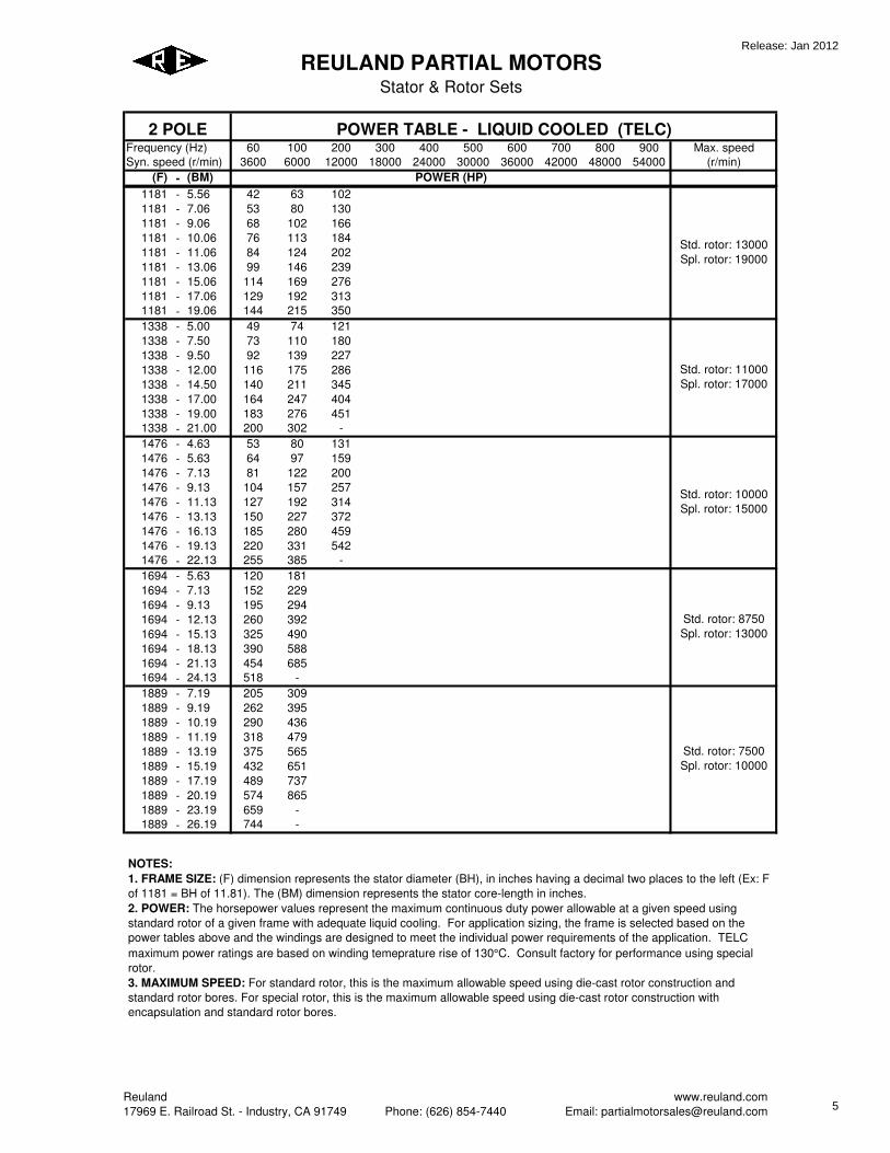
1181 - 5.56 42 63 102
1181 - 7.06 53 80 130
1181 - 9.06 68 102 166
1181 - 10.06 76 113 184
1181 - 11.06 84 124 202
1181 - 13.06 99 146 239
1181 - 15.06 114 169 276
1181 - 17.06 129 192 313
1181 - 19.06 144 215 350
1338 - 5.00 49 74 121
1338 - 7.50 73 110 180
1338 - 9.50 92 139 227
1338 - 12.00 116 175 286
1338 - 14.50 140 211 345
1338 - 17.00 164 247 404
1338 - 19.00 183 276 451
1338 - 21.00 200 302 -
1476 - 4.63 53 80 131
1476 - 5.63 64 97 159
1476 - 7.13 81 122 200
1476 - 9.13 104 157 257
1476 - 11.13 127 192 314
1476 - 13.13 150 227 372
1476 - 16.13 185 280 459
1476 - 19.13 220 331 542
1476 - 22.13 255 385 -
1694 - 5.63 120 181
1694 - 7.13 152 229
1694 - 9.13 195 294
1694 - 12.13 260 392
1694 - 15.13 325 490
1694 - 18.13 390 588
1694 - 21.13 454 685
1694 - 24.13 518 -
1889 - 7.19 205 309
1889 - 9.19 262 395
1889 - 10.19 290 436
1889 - 11.19 318 479
1889 - 13.19 375 565
1889 - 15.19 432 651
1889 - 17.19 489 737
1889 - 20.19 574 865
1889 - 23.19 659 -
1889 - 26.19 744 -
Std. rotor: 8750
Spl. rotor: 13000
Std. rotor: 7500
Spl. rotor: 10000
Std. rotor: 13000
Spl. rotor: 19000
Std. rotor: 11000
Spl. rotor: 17000
Std. rotor: 10000
Spl. rotor: 15000
NOTES:
1. FRAME SIZE: (F) dimension represents the stator diameter (BH), in inches having a decimal two places to the left (Ex: F
of 1181 = BH of 11.81). The (BM) dimension represents the stator core-length in inches.
2. POWER: The horsepower values represent the maximum continuous duty power allowable at a given speed using
standard rotor of a given frame with adequate liquid cooling. For application sizing, the frame is selected based on the
power tables above and the windings are designed to meet the individual power requirements of the application. TELC
maximum power ratings are based on winding temeprature rise of 130°C. Consult factory for performance using special
rotor.
3. MAXIMUM SPEED: For standard rotor, this is the maximum allowable speed using die-cast rotor construction and
standard rotor bores. For special rotor, this is the maximum allowable speed using die-cast rotor construction with
encapsulation and standard rotor bores.
Reuland
17969 E. Railroad St. - Industry, CA 91749 Phone: (626) 854-7440
www.reuland.com
Email: [email protected]
Release: Jan 2012
5

60 100 200 300 400 500 600 700 800 900 Max. speed
3600 6000 12000 18000 24000 30000 36000 42000 48000 54000 (r/min)
(F) - (BM)
315 - 0.98 0.06 0.075 0.1 0.12 0.12 0.12 0.11 0.1 0.1 0.1
315 - 2.17 0.21 0.26 0.35 0.4 0.42 0.42 0.4 0.39 0.37 0.35
315 - 3.15 0.4 0.49 0.66 0.77 0.78 0.78 0.75 0.71 0.68 0.66
315 - 3.94 0.5 0.63 0.87 1 1.05 1.05 1 0.95 0.9 0.87
354 - 1.77 0.26 0.31 0.43 0.5 0.52 0.52 0.49 0.46 0.43
354 - 2.36 0.43 0.52 0.78 0.87 0.87 0.87 0.83 0.78 0.75
354 - 3.15 0.7 0.87 1.2 1.3 1.3 1.3 1.2 1.2 1.1
354 - 3.94 1 1.2 1.5 1.7 1.7 1.7 1.6 1.5 1.4
419 - 1.77 0.35 0.47 0.7 0.7 0.7 0.7 0.52
419 - 2.56 0.61 0.87 1.2 1.2 1.2 1.2 1.1
419 - 3.15 1 1.3 1.9 1.9 1.9 1.7 1.5
419 - 3.94 1.4 1.8 2.6 2.8 2.8 2.6 2.2
419 - 4.72 1.7 2.2 3.3 3.5 3.5 3.1 2.8
472 - 1.50 0.43 0.61 0.87 0.87 0.87 0.87 0.7
472 - 2.25 0.78 1 1.5 1.5 1.5 1.5 1.3
472 - 3.00 1.2 1.5 2.3 2.4 2.4 2.3 2.1
472 - 3.75 1.7 2.3 3.3 3.5 3.5 3.3 3.1
472 - 4.75 2.3 3 4.3 4.5 4.5 4.3 4.1
472 - 5.75 2.8 3.8 5.6 5.7 5.7 5.4 5.2
472 - 6.75 3.5 4.5 6.6 7 7 6.6 6.3
472 - 7.75 4 5.3 7.7 8 8 7.7 7.4
532 - 1.50 0.7 0.87 1.1 1.1 1.1 1.1
532 - 2.00 1.1 1.4 1.7 1.7 1.7 1.6
532 - 2.75 1.6 2.3 2.6 2.8 2.7 2.5
532 - 4.25 2.8 3.8 4.7 4.9 4.7 4.5
532 - 5.75 4.2 5.7 7 7.3 7 6.6
532 - 7.25 5.4 7.3 8.9 9.3 9 8.5
622 - 2.00 1.9 2.6 3 2.8 2.8
622 - 2.75 2.8 3.7 4.3 4.2 4
622 - 3.87 4 5.3 6.1 6 5.8
622 - 4.25 4.7 6.1 7.2 7 6.8
622 - 5.75 7 8.9 10.6 10.3 10
622 - 7.25 8.8 11 13.5 13 12.5
622 - 10.75 13 16.5 20 19.5 19
782 - 1.69 2.8 3.5 4.2 4.2
782 - 2.44 4.3 5.6 6.6 6.6
782 - 2.94 5.2 7 8.2 8.2
782 - 3.94 7.2 9.2 11 11
782 - 5.44 10 12.5 15 15
782 - 6.94 13 16 19 19
782 - 7.94 15 18.5 22 22
782 - 8.94 16.5 21 25 25
782 - 9.94 19 23.5 28 28
782 - 10.94 21 26 31 31
945 - 2.94 8.5 9.7 10.5 9.9
945 - 3.44 11.5 13 14.5 13
945 - 4.69 16 17.5 19 18
945 - 5.94 20 22.5 24.5 22.5
945 - 7.94 26.5 30 33 30
945 - 9.94 33 38 42 39
945 - 11.94 40 45 50 46
945 - 13.94 47 52 58 53
1063 - 2.75 10 11 12.5
1063 - 4.00 15 16.5 18.5
1063 - 6.00 22.5 25 27.5
1063 - 7.00 26 29 32
1063 - 9.00 33 37 41
1063 - 10.50 38 43 48
1063 - 12.50 46 51 56
1063 - 14.50 53 60 66
1063 - 16.50 60 68 76
REULAND PARTIAL MOTORS
Stator & Rotor Sets
POWER (HP)
Std. rotor: 48000
Std. rotor: 36000
Std. rotor: 36000
Std. rotor: 54000
Std. rotor: 14000
Spl. rotor: 21000
Std. rotor: 30000
Std. rotor: 25000
Spl. rotor: 40000
Std. rotor: 19000
Spl. rotor: 30000
Std. rotor: 16000
Spl. rotor: 25000
Frequency (Hz)
Syn. speed (r/min)
2 POLE POWER TABLE - FAN COOLED (TEFC)
Reuland
17969 E. Railroad St. - Industry, CA 91749 Phone: (626) 854-7440
www.reuland.com
Email: [email protected]
Release: Jan 2012
6

60 100 200 300 400 500 600 700 800 900 Max. speed
3600 6000 12000 18000 24000 30000 36000 42000 48000 54000 (r/min)
(F) - (BM)
REULAND PARTIAL MOTORS
Stator & Rotor Sets
POWER (HP)
Frequency (Hz)
Syn. speed (r/min)
2 POLE POWER TABLE - FAN COOLED (TEFC)
1181 - 5.56 29 32 34
1181 - 7.06 36 40 44
1181 - 9.06 46 52 56
1181 - 10.06 52 58 62
1181 - 11.06 58 64 68
1181 - 13.06 68 76 82
1181 - 15.06 78 86 94
1181 - 17.06 88 98 106
1181 - 19.06 98 110 118
1338 - 5.00 33 37 40
1338 - 7.50 49 55 59
1338 - 9.50 62 70 74
1338 - 12.00 78 88 94
1338 - 14.50 94 106 114
1338 - 17.00 110 124 134
1338 - 19.00 124 138 148
1338 - 21.00 136 152 162
1476 - 4.63 36 38 40
1476 - 5.63 43 46 48
1476 - 7.13 54 57 61
1476 - 9.13 69 73 78
1476 - 11.13 85 90 95
1476 - 13.13 101 107 113
1476 - 16.13 124 132 139
1476 - 19.13 149 158 166
1476 - 22.13 172 182 193
1694 - 5.63 56 60
1694 - 7.13 71 76
1694 - 9.13 90 97
1694 - 12.13 120 129
1694 - 15.13 152 161
1694 - 18.13 182 193
1694 - 21.13 211 225
1694 - 24.13 241 257
1889 - 7.19 114 123
1889 - 9.19 147 156
1889 - 10.19 162 174
1889 - 11.19 180 192
1889 - 13.19 210 225
1889 - 15.19 243 261
1889 - 17.19 276 294
1889 - 20.19 324 345
1889 - 23.19 372 396
1889 - 26.19 420 447
Std. rotor: 8750
Spl. rotor: 13000
Std. rotor: 7500
Spl. rotor: 10000
Std. rotor: 13000
Spl. rotor: 19000
Std. rotor: 11000
Spl. rotor: 17000
Std. rotor: 10000
Spl. rotor: 15000
NOTES:
1. FRAME SIZE: (F) dimension represents the stator diameter (BH), in inches having a decimal two places to the left (Ex: F
of 1181 = BH of 11.81). The (BM) dimension represents the stator core-length in inches.
2. POWER: The horsepower values represent the maximum continuous duty power allowable at a given speed using
standard rotor of a given frame with adequate air cooling. For application sizing, the frame is selected based on the power
tables above and the windings are designed to meet the individual power requirements of the application. TEFC maximum
power ratings are based on winding temeprature rise of 80°C. Consult factory for performance using special rotor.
3. MAXIMUM SPEED: For standard rotor, this is the maximum allowable speed using die-cast rotor construction and
standard rotor bores. For special rotor, this is the maximum allowable speed using die-cast rotor construction with
encapsulation and standard rotor bores.
Reuland
17969 E. Railroad St. - Industry, CA 91749 Phone: (626) 854-7440
www.reuland.com
Email: [email protected]
Release: Jan 2012
7
60 100 200 300 400 500 600 700 800 900 Max. speed
3600 6000 12000 18000 24000 30000 36000 42000 48000 54000 (r/min)
(F) - (BM)
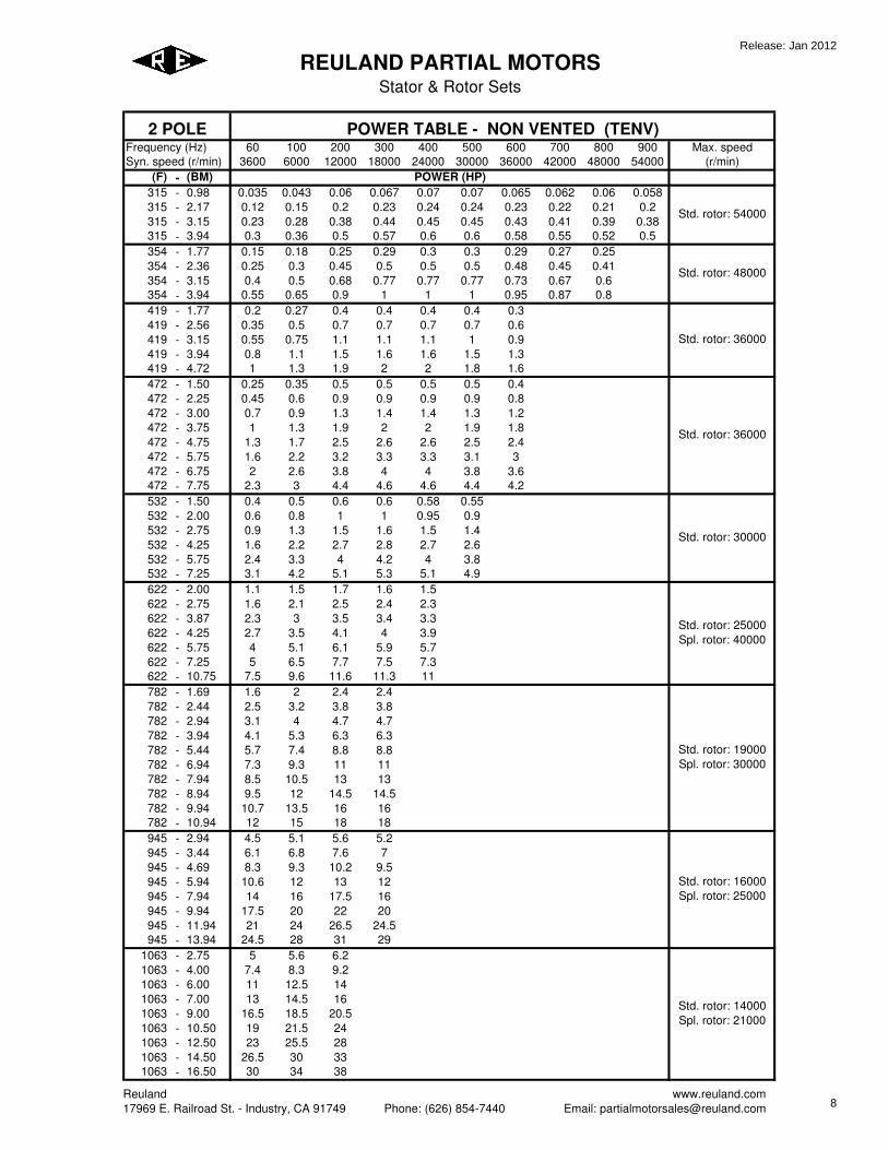
315 - 0.98 0.035 0.043 0.06 0.067 0.07 0.07 0.065 0.062 0.06 0.058
315 - 2.17 0.12 0.15 0.2 0.23 0.24 0.24 0.23 0.22 0.21 0.2
315 - 3.15 0.23 0.28 0.38 0.44 0.45 0.45 0.43 0.41 0.39 0.38
315 - 3.94 0.3 0.36 0.5 0.57 0.6 0.6 0.58 0.55 0.52 0.5
354 - 1.77 0.15 0.18 0.25 0.29 0.3 0.3 0.29 0.27 0.25
354 - 2.36 0.25 0.3 0.45 0.5 0.5 0.5 0.48 0.45 0.41
354 - 3.15 0.4 0.5 0.68 0.77 0.77 0.77 0.73 0.67 0.6
354 - 3.94 0.55 0.65 0.9 1 1 1 0.95 0.87 0.8
419 - 1.77 0.2 0.27 0.4 0.4 0.4 0.4 0.3
419 - 2.56 0.35 0.5 0.7 0.7 0.7 0.7 0.6
419 - 3.15 0.55 0.75 1.1 1.1 1.1 1 0.9
419 - 3.94 0.8 1.1 1.5 1.6 1.6 1.5 1.3
419 - 4.72 1 1.3 1.9 2 2 1.8 1.6
472 - 1.50 0.25 0.35 0.5 0.5 0.5 0.5 0.4
472 - 2.25 0.45 0.6 0.9 0.9 0.9 0.9 0.8
472 - 3.00 0.7 0.9 1.3 1.4 1.4 1.3 1.2
472 - 3.75 1 1.3 1.9 2 2 1.9 1.8
472 - 4.75 1.3 1.7 2.5 2.6 2.6 2.5 2.4
472 - 5.75 1.6 2.2 3.2 3.3 3.3 3.1 3
472 - 6.75 2 2.6 3.8 4 4 3.8 3.6
472 - 7.75 2.3 3 4.4 4.6 4.6 4.4 4.2
532 - 1.50 0.4 0.5 0.6 0.6 0.58 0.55
532 - 2.00 0.6 0.8 1 1 0.95 0.9
532 - 2.75 0.9 1.3 1.5 1.6 1.5 1.4
532 - 4.25 1.6 2.2 2.7 2.8 2.7 2.6
532 - 5.75 2.4 3.3 4 4.2 4 3.8
532 - 7.25 3.1 4.2 5.1 5.3 5.1 4.9
622 - 2.00 1.1 1.5 1.7 1.6 1.5
622 - 2.75 1.6 2.1 2.5 2.4 2.3
622 - 3.87 2.3 3 3.5 3.4 3.3
622 - 4.25 2.7 3.5 4.1 4 3.9
622 - 5.75 4 5.1 6.1 5.9 5.7
622 - 7.25 5 6.5 7.7 7.5 7.3
622 - 10.75 7.5 9.6 11.6 11.3 11
782 - 1.69 1.6 2 2.4 2.4
782 - 2.44 2.5 3.2 3.8 3.8
782 - 2.94 3.1 4 4.7 4.7
782 - 3.94 4.1 5.3 6.3 6.3
782 - 5.44 5.7 7.4 8.8 8.8
782 - 6.94 7.3 9.3 11 11
782 - 7.94 8.5 10.5 13 13
782 - 8.94 9.5 12 14.5 14.5
782 - 9.94 10.7 13.5 16 16
782 - 10.94 12 15 18 18
945 - 2.94 4.5 5.1 5.6 5.2
945 - 3.44 6.1 6.8 7.6 7
945 - 4.69 8.3 9.3 10.2 9.5
945 - 5.94 10.6 12 13 12
945 - 7.94 14 16 17.5 16
945 - 9.94 17.5 20 22 20
945 - 11.94 21 24 26.5 24.5
945 - 13.94 24.5 28 31 29
1063 - 2.75 5 5.6 6.2
1063 - 4.00 7.4 8.3 9.2
1063 - 6.00 11 12.5 14
1063 - 7.00 13 14.5 16
1063 - 9.00 16.5 18.5 20.5
1063 - 10.50 19 21.5 24
1063 - 12.50 23 25.5 28
1063 - 14.50 26.5 30 33
1063 - 16.50 30 34 38
REULAND PARTIAL MOTORS
Stator & Rotor Sets
Frequency (Hz)
Syn. speed (r/min)
2 POLE POWER TABLE - NON VENTED (TENV)
Std. rotor: 19000
Spl. rotor: 30000
Std. rotor: 16000
Spl. rotor: 25000
Std. rotor: 48000
Std. rotor: 36000
Std. rotor: 36000
POWER (HP)
Std. rotor: 54000
Std. rotor: 14000
Spl. rotor: 21000
Std. rotor: 30000
Std. rotor: 25000
Spl. rotor: 40000
Reuland
17969 E. Railroad St. - Industry, CA 91749 Phone: (626) 854-7440
www.reuland.com
Email: [email protected]
Release: Jan 2012
8
60 100 200 300 400 500 600 700 800 900 Max. speed
3600 6000 12000 18000 24000 30000 36000 42000 48000 54000 (r/min)
(F) - (BM)
REULAND PARTIAL MOTORS
Stator & Rotor Sets
Frequency (Hz)
Syn. speed (r/min)
2 POLE POWER TABLE - NON VENTED (TENV)
POWER (HP)
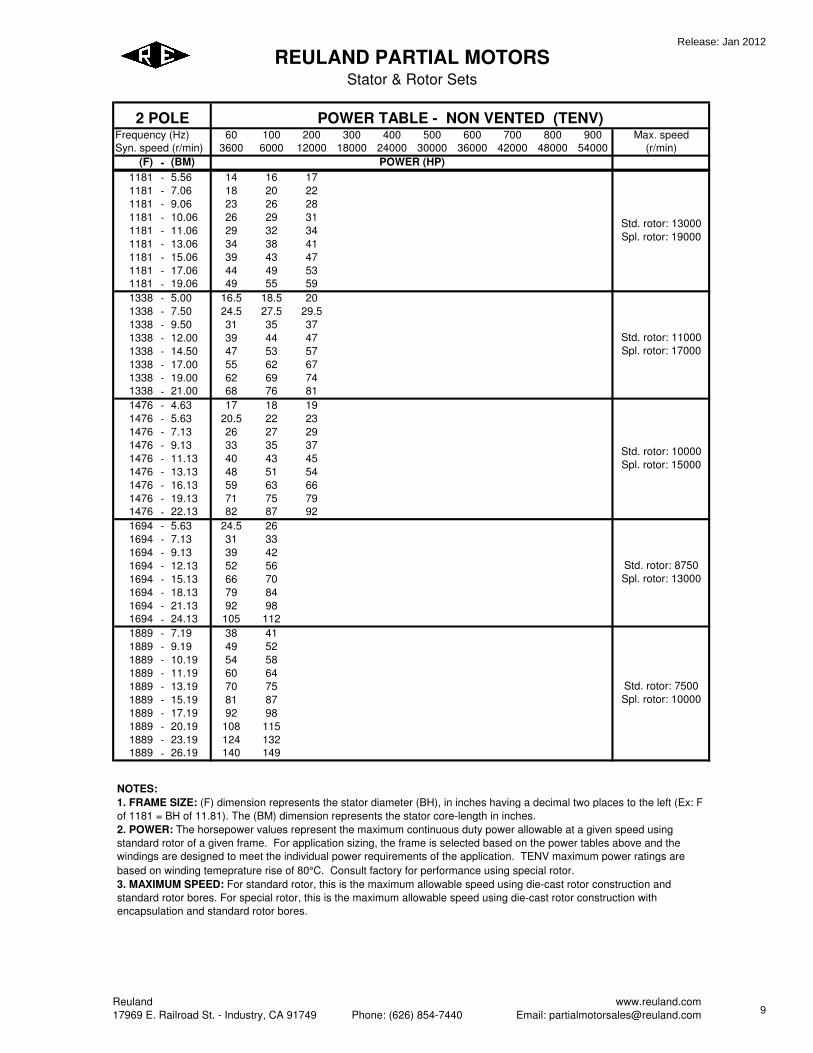
1181 - 5.56 14 16 17
1181 - 7.06 18 20 22
1181 - 9.06 23 26 28
1181 - 10.06 26 29 31
1181 - 11.06 29 32 34
1181 - 13.06 34 38 41
1181 - 15.06 39 43 47
1181 - 17.06 44 49 53
1181 - 19.06 49 55 59
1338 - 5.00 16.5 18.5 20
1338 - 7.50 24.5 27.5 29.5
1338 - 9.50 31 35 37
1338 - 12.00 39 44 47
1338 - 14.50 47 53 57
1338 - 17.00 55 62 67
1338 - 19.00 62 69 74
1338 - 21.00 68 76 81
1476 - 4.63 17 18 19
1476 - 5.63 20.5 22 23
1476 - 7.13 26 27 29
1476 - 9.13 33 35 37
1476 - 11.13 40 43 45
1476 - 13.13 48 51 54
1476 - 16.13 59 63 66
1476 - 19.13 71 75 79
1476 - 22.13 82 87 92
1694 - 5.63 24.5 26
1694 - 7.13 31 33
1694 - 9.13 39 42
1694 - 12.13 52 56
1694 - 15.13 66 70
1694 - 18.13 79 84
1694 - 21.13 92 98
1694 - 24.13 105 112
1889 - 7.19 38 41
1889 - 9.19 49 52
1889 - 10.19 54 58
1889 - 11.19 60 64
1889 - 13.19 70 75
1889 - 15.19 81 87
1889 - 17.19 92 98
1889 - 20.19 108 115
1889 - 23.19 124 132
1889 - 26.19 140 149
Std. rotor: 8750
Spl. rotor: 13000
Std. rotor: 7500
Spl. rotor: 10000
Std. rotor: 13000
Spl. rotor: 19000
Std. rotor: 11000
Spl. rotor: 17000
Std. rotor: 10000
Spl. rotor: 15000
NOTES:
1. FRAME SIZE: (F) dimension represents the stator diameter (BH), in inches having a decimal two places to the left (Ex: F
of 1181 = BH of 11.81). The (BM) dimension represents the stator core-length in inches.
2. POWER: The horsepower values represent the maximum continuous duty power allowable at a given speed using
standard rotor of a given frame. For application sizing, the frame is selected based on the power tables above and the
windings are designed to meet the individual power requirements of the application. TENV maximum power ratings are
based on winding temeprature rise of 80°C. Consult factory for performance using special rotor.
3. MAXIMUM SPEED: For standard rotor, this is the maximum allowable speed using die-cast rotor construction and
standard rotor bores. For special rotor, this is the maximum allowable speed using die-cast rotor construction with
encapsulation and standard rotor bores.
Reuland
17969 E. Railroad St. - Industry, CA 91749 Phone: (626) 854-7440
www.reuland.com
Email: [email protected]
Release: Jan 2012
9

Reuland www.reuland.com 17969 E. Railroad St. – Industry, CA 91749 Phone: (626) 854-7440 Email: [email protected]
REULAND PARTIAL MOTORS
Stator & Rotor Sets
2 POLE PRODUCT CODE
SHELL
EN
CLO
SU
RE
FRAME SIZE (F)
CORE LENGTH
(BM) # OF
POLES
ROTOR ID BORE
(CA) ROTOR OD
(DB)
ROTOR FIN
CODE SENSOR
CODE
_
_ 2 _
_
S - FOR
THE STANDARD
SHELL (SEE
STATOR TABLE )
C - FOR A CUSTOM
SHELL
X - NO SHELL/
BLANKED STATOR
OD
M - NO SHELL/
MACHINED STATOR
L -
LIQUID COOLED (TELC)
F - FAN
COOLED (TEFC)
N - NON VENTED (TENV)
FRAME SIZE (F)
SEE
POWER TABLES
CORE
LENGTH (BM)
SEE
POWER TABLES
( A ) FOR BLANKED
Ø ( A )
( B ) FOR BLANKED
Ø ( B )
( C ) FOR CUSTOM
MACHINED Ø
SEE ROTOR TABLE
( P ) FOR
PUNCHED DIAMETER
(SEE STAMPED STATOR ID ON STATOR
TABLE)
( M ) FOR STANDARD MACHINED DIAMETER
(SEE ROTOR TABLE)
( C ) FOR CUSTOM
MACHINED DIAMETER
ROTOR
FINS REQUIRED
Y - YES N - NO
ENTER VALUE FROM ROW 1
OF SENSOR TABLE
LEGEND
1. SHELL: Determine if a shell is required for the application. If a custom shell is required consult factory for availability.
2. ENCLOSURE: Type of cooling (TELC, TEFC & TENV). 3. FRAME SIZE (F): See power tables & dimension tables for required frame. 4. CORE LENGTH (BM): See power tables for required core length. Custom lengths
available, consult factory. 5. ROTOR ID BORE (CA): See dimension tables for available blanked diameters. Consult
factory for custom rotor ID’s. 6. ROTOR OD (DB): See dimension tables for blanked diameters, standard machined
diameters or consult factory for custom machined diameters. 7. ROTOR FIN CODE: Are rotor fins required? 8. SENSOR CODE: See sensor code table for configurations. Consult factory for other
options.
Release: Jan 2012
10

Reuland www.reuland.com 17969 E. Railroad St. – Industry, CA 91749 Phone: (626) 854-7440 Email: [email protected]
REULAND PARTIAL MOTORS
Stator & Rotor Sets
2 POLE DATA
STATOR
FRAME
SIZE
STAMPED
STATOR
ID BH
( SHELL )
BHS
( SHELL )
BMS
W¹
(max)
LEAD
SIDE
W²
(max)
BL
(max)
315 1.574 3.149 3.500 BM + 0.5 .78 .95 2.9 354 1.772 3.543 4.000 BM + 0.5 .85 1.00 3.3 419 2.560 4.192 4.500 BM + 0.5 1.00 1.25 3.8 472 2.441 4.723 4.703 BM + 0.47 1.15 1.40 4.5 532 2.756 5.314 5.703 BM + 0.47 1.25 1.50 5.2 622 3.347 6.222 6.468 BM + 0.47 1.35 1.70 6 782 4.331 7.814 8.000 BM + 1.19 1.50 2.00 7.5 945 5.315 9.447 10.000 BM + 1.19 2.00 2.25 9.2
1063 5.905 10.629 11.000 BM + 1.06 2.25 2.50 10.1 1181 6.500 11.810 12.375 BM + 1.06 2.50 2.75 11.5 1338 7.480 13.386 14.000 BM + 3 3.00 3.25 12.5 1476 8.465 14.763 15.000 BM + 3.37 3.25 3.50 13.8 1694 9.448 16.949 17.500 BM + 3.37 3.50 4.00 16.5 1889 11.417 18.897 19.500 BM + 3.31 4.50 5.00 18.5
ROTOR
(without fins) (with fins)
CA
(blanked Ø) FRAME
SIZE
DB
(mach.)
BO
(mach.) BR H BR H H¹ A B
CA
(mach.)
(max)
315 1.554 BM - - - - - - - 0.687 354 1.752 BM - - - - - - - 0.75 419 2.536 BM + 0.25 1.660 .315 - - - .710 .748 1.5 472 2.411 BM + 0.25 1.378 .400 1.378 .400 .750 .984 - *1.4 532 2.726 BM + 0.25 1.650 .600 1.789 .750 1.050 .990 - 1.57 622 3.317 BM + 0.25 2.000 .531 2.000 .531 1.000 .990 1.490 *2.3 782 4.291 BM + 0.25 2.500 .550 2.500 .625 1.250 1.490 1.990 *2.7 945 5.275 BM + 0.25 3.090 .750 3.090 .750 1.500 1.740 2.165 *3.2 1063 5.855 BM + 0.25 3.750 .875 3.750 .875 1.875 1.990 2.559 3.6 1181 6.44 BM + 0.25 3.500 .950 - - - 2.490 2.952 *3.9 1338 7.41 BM + 0.25 4.200 .781 3.380 .781 2.500 2.740 3.149 4.1 1476 8.385 BM + 0.25 4.800 1.000 4.800 1.000 1.700 2.740 3.346 4.5 1654 9.358 BM + 0.25 5.850 1.350 - - - 3.937 4.331 5.5 1889 11.307 BM + 0.25 6.572 1.590 - - - 4.331 4.724 6.3
* requires use of a non standard end ring with large “BR” or machining of “BR” dimension to achieve max. “CA” dimension.
Release: Jan 2012
11
Reuland www.reuland.com 17969 E. Railroad St. – Industry, CA 91749 Phone: (626) 854-7440 Email: [email protected]
REULAND PARTIAL MOTORS
Stator & Rotor Sets
TOLERANCE
w/shell w/out shell
±.250 BJ ±.250 - BH +0.003/-0.002
0.000/-0.002 BHS - - BM ±.060
0.000/-0.030 BMS - ±.030 BO ±.030
±.200 BL ±.200 0.000/-0.001 CA 0.000/-0.001
±.025 BR ±.025 ±.200 BP ±.200 ±.001 DB* ±.001
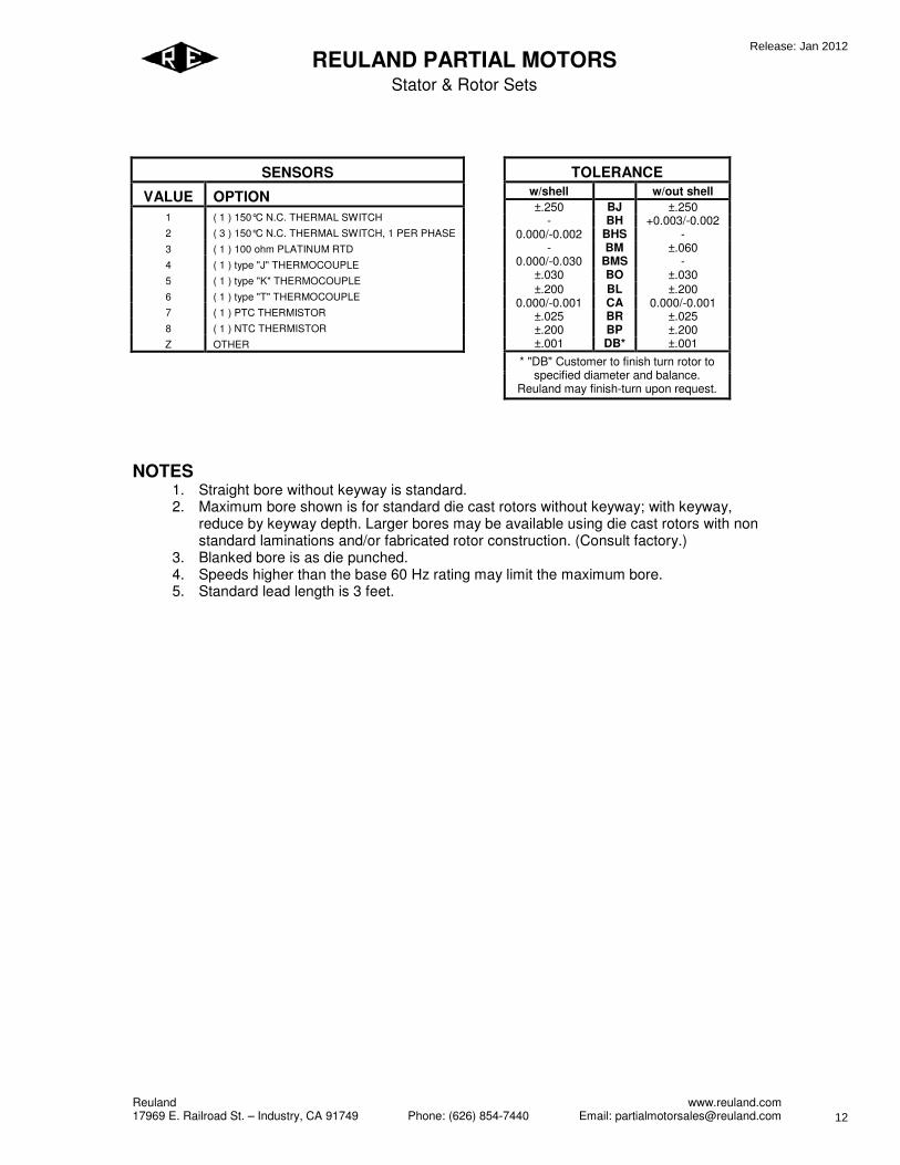
* "DB" Customer to finish turn rotor to specified diameter and balance.
Reuland may finish-turn upon request.
NOTES
1. Straight bore without keyway is standard. 2. Maximum bore shown is for standard die cast rotors without keyway; with keyway,
reduce by keyway depth. Larger bores may be available using die cast rotors with non standard laminations and/or fabricated rotor construction. (Consult factory.)
3. Blanked bore is as die punched. 4. Speeds higher than the base 60 Hz rating may limit the maximum bore. 5. Standard lead length is 3 feet.
SENSORS
VALUE OPTION
1 ( 1 ) 150°C N.C. THERMAL SWITCH
2 ( 3 ) 150°C N.C. THERMAL SWITCH, 1 PER PHASE
3 ( 1 ) 100 ohm PLATINUM RTD
4 ( 1 ) type "J" THERMOCOUPLE
5 ( 1 ) type "K" THERMOCOUPLE
6 ( 1 ) type "T" THERMOCOUPLE
7 ( 1 ) PTC THERMISTOR
8 ( 1 ) NTC THERMISTOR
Z OTHER
Release: Jan 2012
12
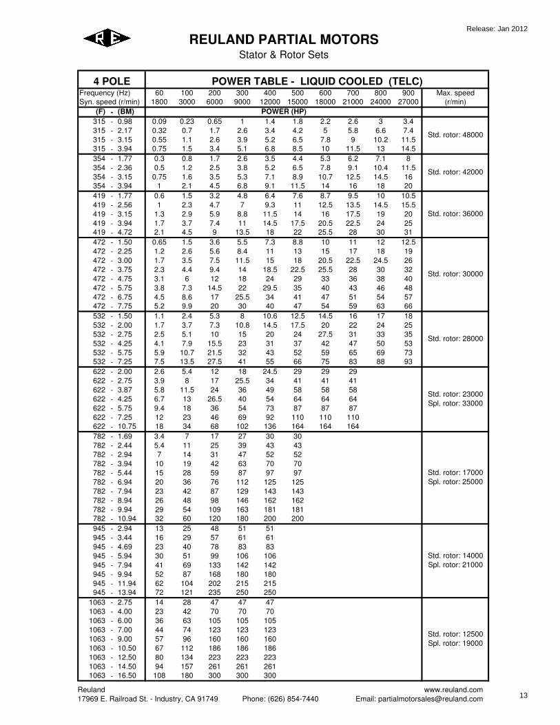
60 100 200 300 400 500 600 700 800 900 Max. speed
1800 3000 6000 9000 12000 15000 18000 21000 24000 27000 (r/min)
(F) - (BM)
315 - 0.98 0.09 0.23 0.65 1 1.4 1.8 2.2 2.6 3 3.4
315 - 2.17 0.32 0.7 1.7 2.6 3.4 4.2 5 5.8 6.6 7.4
315 - 3.15 0.55 1.1 2.6 3.9 5.2 6.5 7.8 9 10.2 11.5
315 - 3.94 0.75 1.5 3.4 5.1 6.8 8.5 10 11.5 13 14.5
354 - 1.77 0.3 0.8 1.7 2.6 3.5 4.4 5.3 6.2 7.1 8
354 - 2.36 0.5 1.2 2.5 3.8 5.2 6.5 7.8 9.1 10.4 11.5
354 - 3.15 0.75 1.6 3.5 5.3 7.1 8.9 10.7 12.5 14.5 16
354 - 3.94 1 2.1 4.5 6.8 9.1 11.5 14 16 18 20
419 - 1.77 0.6 1.5 3.2 4.8 6.4 7.6 8.7 9.5 10 10.5
419 - 2.56 1 2.3 4.7 7 9.3 11 12.5 13.5 14.5 15.5
419 - 3.15 1.3 2.9 5.9 8.8 11.5 14 16 17.5 19 20
419 - 3.94 1.7 3.7 7.4 11 14.5 17.5 20.5 22.5 24 25
419 - 4.72 2.1 4.5 9 13.5 18 22 25.5 28 30 31
472 - 1.50 0.65 1.5 3.6 5.5 7.3 8.8 10 11 12 12.5
472 - 2.25 1.2 2.6 5.6 8.4 11 13 15 17 18 19
472 - 3.00 1.7 3.5 7.5 11.5 15 18 20.5 22.5 24.5 26
472 - 3.75 2.3 4.4 9.4 14 18.5 22.5 25.5 28 30 32
472 - 4.75 3.1 6 12 18 24 29 33 36 38 40
472 - 5.75 3.8 7.3 14.5 22 29.5 35 40 43 46 48
472 - 6.75 4.5 8.6 17 25.5 34 41 47 51 54 57
472 - 7.75 5.2 9.9 20 30 40 47 54 59 63 66
532 - 1.50 1.1 2.4 5.3 8 10.6 12.5 14.5 16 17 18
532 - 2.00 1.7 3.7 7.3 10.8 14.5 17.5 20 22 24 25
532 - 2.75 2.5 5.1 10 15 20 24 27.5 31 33 35
532 - 4.25 4.1 7.9 15.5 23 31 37 42 47 50 53
532 - 5.75 5.9 10.7 21.5 32 43 52 59 65 69 73
532 - 7.25 7.5 13.5 27.5 41 55 66 75 83 88 93
622 - 2.00 2.6 5.4 12 18 24.5 29 29 29
622 - 2.75 3.9 8 17 25.5 34 41 41 41
622 - 3.87 5.8 11.5 24 36 49 58 58 58
622 - 4.25 6.7 13 26.5 40 54 64 64 64
622 - 5.75 9.4 18 36 54 73 87 87 87
622 - 7.25 12 23 46 69 92 110 110 110
622 - 10.75 18 34 68 102 136 164 164 164
782 - 1.69 3.4 7 17 27 30 30
782 - 2.44 5.4 11 25 39 43 43
782 - 2.94 7 14 31 47 52 52
782 - 3.94 10 19 42 63 70 70
782 - 5.44 15 28 59 87 97 97
782 - 6.94 20 36 76 112 125 125
782 - 7.94 23 42 87 129 143 143
782 - 8.94 26 48 98 146 162 162
782 - 9.94 29 54 109 163 181 181
782 - 10.94 32 60 120 180 200 200
945 - 2.94 13 25 48 51 51
945 - 3.44 16 29 57 61 61
945 - 4.69 23 40 78 83 83
945 - 5.94 30 51 99 106 106
945 - 7.94 41 69 133 142 142
945 - 9.94 52 87 168 180 180
945 - 11.94 62 104 202 215 215
945 - 13.94 72 121 235 250 250
1063 - 2.75 14 28 47 47 47
1063 - 4.00 23 42 70 70 70
1063 - 6.00 36 63 105 105 105
1063 - 7.00 44 74 123 123 123
1063 - 9.00 57 96 160 160 160
1063 - 10.50 67 112 186 186 186
1063 - 12.50 80 134 223 223 223
1063 - 14.50 94 157 261 261 261
1063 - 16.50 108 180 300 300 300
REULAND PARTIAL MOTORS
Stator & Rotor Sets
POWER (HP)
Std. rotor: 42000
Std. rotor: 36000
Std. rotor: 30000
Std. rotor: 48000
Std. rotor: 12500
Spl. rotor: 19000
Std. rotor: 28000
Std. rotor: 23000
Spl. rotor: 33000
Std. rotor: 17000
Spl. rotor: 25000
Std. rotor: 14000
Spl. rotor: 21000
Frequency (Hz)
Syn. speed (r/min)
4 POLE POWER TABLE - LIQUID COOLED (TELC)
Reuland
17969 E. Railroad St. - Industry, CA 91749 Phone: (626) 854-7440
www.reuland.com
Email: [email protected]
Release: Jan 2012
13

60 100 200 300 400 500 600 700 800 900 Max. speed
1800 3000 6000 9000 12000 15000 18000 21000 24000 27000 (r/min)
(F) - (BM)
REULAND PARTIAL MOTORS
Stator & Rotor Sets
POWER (HP)
Frequency (Hz)
Syn. speed (r/min)
4 POLE POWER TABLE - LIQUID COOLED (TELC)
1181 - 5.56 49 82 99 99
1181 - 7.06 63 105 126 126
1181 - 9.06 81 135 163 163
1181 - 10.06 90 150 181 181
1181 - 11.06 99 166 200 200
1181 - 13.06 117 197 238 238
1181 - 15.06 136 228 275 275
1181 - 17.06 155 259 313 313
1181 - 19.06 174 290 350 350
1338 - 5.00 57 96 106 106
1338 - 7.50 86 145 160 160
1338 - 9.50 110 184 202 202
1338 - 12.00 139 233 256 256
1338 - 14.50 168 282 310 310
1338 - 17.00 198 331 364 364
1338 - 19.00 222 370 406 406
1338 - 21.00 246 410 450 450
1476 - 4.63 64 107 112 112
1476 - 5.63 78 131 137 137
1476 - 7.13 99 167 175 175
1476 - 9.13 128 214 225 225
1476 - 11.13 157 262 275 275
1476 - 13.13 186 310 325 325
1476 - 16.13 229 381 400 400
1476 - 19.13 272 453 475 475
1476 - 22.13 315 525 550 550
1694 - 5.63 105 176 176
1694 - 7.13 133 223 223
1694 - 9.13 171 286 286
1694 - 12.13 228 381 381
1694 - 15.13 285 475 475
1694 - 18.13 342 570 570
1694 - 21.13 399 665 665
1694 - 24.13 456 760 760
1889 - 7.19 195 297 297
1889 - 9.19 250 382 382
1889 - 10.19 278 424 424
1889 - 11.19 306 466 466
1889 - 13.19 361 550 550
1889 - 15.19 416 635 635
1889 - 17.19 471 719 719
1889 - 20.19 554 846 846
1889 - 23.19 637 972 972
1889 - 26.19 720 1100 -
Std. rotor: 8000
Spl. rotor: 11000
Std. rotor: 6500
Spl. rotor: 9000
Std. rotor: 11000
Spl. rotor: 17000
Std. rotor: 10000
Spl. rotor: 15000
Std. rotor: 9000
Spl. rotor: 13000
NOTES:
1. FRAME SIZE: (F) dimension represents the stator diameter (BH), in inches having a decimal two places to the left (Ex: F
of 1181 = BH of 11.81). The (BM) dimension represents the stator core-length in inches.
2. POWER: The horsepower values represent the maximum continuous duty power allowable at a given speed using
standard rotor of a given frame with adequate liquid cooling. For application sizing, the frame is selected based on the
power tables above and the windings are designed to meet the individual power requirements of the application. TELC
maximum power ratings are based on winding temeprature rise of 130°C. Consult factory for performance using special
rotor.
3. MAXIMUM SPEED: For standard rotor, this is the maximum allowable speed using die-cast rotor construction and
standard rotor bores. For special rotor, this is the maximum allowable speed using die-cast rotor construction with
encapsulation and standard rotor bores.
Reuland
17969 E. Railroad St. - Industry, CA 91749 Phone: (626) 854-7440
www.reuland.com
Email: [email protected]
Release: Jan 2012
14

60 100 200 300 400 500 600 700 800 900 Max. speed
1800 3000 6000 9000 12000 15000 18000 21000 24000 27000 (r/min)
(F) - (BM)
315 - 0.98 0.045 0.061 0.09 0.11 0.12 0.12 0.12 0.12 0.11 0.11
315 - 2.17 0.16 0.22 0.33 0.39 0.42 0.42 0.42 0.4 0.39 0.38
315 - 3.15 0.3 0.42 0.63 0.73 0.78 0.78 0.78 0.77 0.76 0.75
315 - 3.94 0.4 0.57 0.84 1 1.05 1.05 1.05 1.03 1.02 1.01
354 - 1.77 0.17 0.24 0.35 0.45 0.52 0.52 0.52 0.49 0.45 0.42
354 - 2.36 0.28 0.45 0.7 0.8 0.87 0.87 0.87 0.83 0.78 0.75
354 - 3.15 0.47 0.75 1.05 1.2 1.3 1.3 1.3 1.2 1.1 1.1
354 - 3.94 0.65 1 1.4 1.6 1.7 1.7 1.7 1.6 1.5 1.5
419 - 1.77 0.33 0.5 0.6 0.7 0.7 0.7 0.66 0.63 0.6 0.56
419 - 2.56 0.57 0.85 1.05 1.2 1.2 1.2 1.1 1.05 0.98 0.95
419 - 3.15 0.84 1.2 1.7 1.9 1.9 1.9 1.8 1.7 1.6 1.5
419 - 3.94 1.1 1.6 2.4 2.8 2.8 2.8 2.6 2.4 2.3 2.2
419 - 4.72 1.5 2.1 3.1 3.5 3.5 3.5 3.3 3.1 2.9 2.8
472 - 1.50 0.35 0.5 0.7 0.87 0.87 0.77 0.66 0.6 0.54 0.5
472 - 2.25 0.63 0.82 1.2 1.5 1.5 1.4 1.2 1.1 1 0.87
472 - 3.00 0.87 1.1 1.7 2.1 2.1 1.8 1.6 1.4 1.3 1.2
472 - 3.75 1.2 1.5 2.4 3.1 3.1 2.7 2.4 2.1 1.9 1.7
472 - 4.75 1.5 2.2 3.3 4.2 4.2 3.7 3.2 2.9 2.6 2.2
472 - 5.75 1.9 2.9 4.2 5.6 5.6 4.9 4.2 3.8 3.4 3
472 - 6.75 2.4 3.5 5 6.5 6.5 5.7 5 4.5 4 3.6
472 - 7.75 2.8 4 6 7.7 7.7 6.9 6.1 5.4 4.9 4.3
532 - 1.50 0.82 1 1.05 1.05 1.05 0.98 0.92 0.85 0.8 0.75
532 - 2.00 1.1 1.5 1.7 1.7 1.7 1.5 1.5 1.4 1.3 1.2
532 - 2.75 1.5 2.2 2.6 2.8 2.8 2.6 2.4 2.2 2.1 1.9
532 - 4.25 2.6 3.4 4.2 4.7 4.7 4.4 4.2 3.8 3.5 3.3
532 - 5.75 4 5 6.3 7.3 7.3 6.8 6.4 6 5.6 5.2
532 - 7.25 5 6.6 8.2 9.2 9.2 8.7 8.2 7.7 7.1 6.6
622 - 2.00 1.7 2.2 2.6 2.9 2.9 2.8 2.6 2.2
622 - 2.75 2.6 3.6 4.2 4.5 4.7 4.3 4 3.6
622 - 3.87 3.8 5.4 6.3 6.8 7 6.4 5.9 5.4
622 - 4.25 4.5 6.3 7.3 7.8 8.2 7.5 7 6.3
622 - 5.75 6.4 8.9 10.5 11 11.5 10.8 9.8 8.9
622 - 7.25 8.2 11 13 14 14.5 13.5 12.5 11
622 - 10.75 12 16 20 22 22.5 21 19.5 17.5
782 - 1.69 2.1 2.6 3.3 3.6 3.3 3.1
782 - 2.44 3.1 4.3 5.4 6.1 5.6 5.2
782 - 2.94 4.3 5.2 7 7.7 7.2 6.4
782 - 3.94 6.3 7.8 10 11 10.5 9.6
782 - 5.44 9.6 12 15 17 15.5 14.5
782 - 6.94 13 16 20 23 21 19
782 - 7.94 15 18.5 23.5 26 24 22
782 - 8.94 17 21 26 29 27 25
782 - 9.94 19 23.5 29 32.5 30.5 28
782 - 10.94 21 26 32 36 34 31
945 - 2.94 8.2 9.7 11 10.5 9.7
945 - 3.44 10.5 12 14 13 12
945 - 4.69 15 17 20 19 17
945 - 5.94 19 22.5 26 24 22.5
945 - 7.94 25.5 30 35 32 30
945 - 9.94 32 39 45 42 39
945 - 11.94 40 47 55 51 47
945 - 13.94 47 55 64 60 55
1063 - 2.75 8.2 10.2 11 10.6 10
1063 - 4.00 13.5 17 18.5 17.5 16.5
1063 - 6.00 21 26 28 27 26
1063 - 7.00 25 32 34 32 31
1063 - 9.00 34 42 46 43 42
1063 - 10.50 39 49 53 51 48
1063 - 12.50 48 60 64 62 58
1063 - 14.50 56 70 75 72 68
1063 - 16.50 64 80 86 82 78
REULAND PARTIAL MOTORS
Stator & Rotor Sets
Frequency (Hz)
Syn. speed (r/min)
4 POLE POWER TABLE - FAN COOLED (TEFC)
Std. rotor: 17000
Spl. rotor: 25000
Std. rotor: 14000
Spl. rotor: 21000
Std. rotor: 42000
Std. rotor: 36000
Std. rotor: 30000
POWER (HP)
Std. rotor: 48000
Std. rotor: 12500
Spl. rotor: 19000
Std. rotor: 28000
Std. rotor: 23000
Spl. rotor: 33000
Reuland
17969 E. Railroad St. - Industry, CA 91749 Phone: (626) 854-7440
www.reuland.com
Email: [email protected]
Release: Jan 2012
15

60 100 200 300 400 500 600 700 800 900 Max. speed
1800 3000 6000 9000 12000 15000 18000 21000 24000 27000 (r/min)
(F) - (BM)
REULAND PARTIAL MOTORS
Stator & Rotor Sets
Frequency (Hz)
Syn. speed (r/min)
4 POLE POWER TABLE - FAN COOLED (TEFC)
POWER (HP)
1181 - 5.56 28 34 38 36
1181 - 7.06 35 43 48 45
1181 - 9.06 44 54 62 58
1181 - 10.06 51 62 70 64
1181 - 11.06 56 68 76 72
1181 - 13.06 66 80 90 84
1181 - 15.06 76 94 104 98
1181 - 17.06 88 106 120 112
1181 - 19.06 98 120 134 126
1338 - 5.00 32 38 42 40
1338 - 7.50 47 58 64 60
1338 - 9.50 60 74 82 78
1338 - 12.00 76 94 104 98
1338 - 14.50 92 114 126 120
1338 - 17.00 110 134 150 140
1338 - 19.00 124 152 170 160
1338 - 21.00 138 168 188 178
1476 - 4.63 36 41 46 43
1476 - 5.63 44 50 57 52
1476 - 7.13 56 63 71 67
1476 - 9.13 71 82 90 86
1476 - 11.13 88 101 111 105
1476 - 13.13 105 120 132 126
1476 - 16.13 128 147 164 153
1476 - 19.13 153 174 195 184
1476 - 22.13 176 202 225 212
1694 - 5.63 64 74 78
1694 - 7.13 81 92 99
1694 - 9.13 102 117 125
1694 - 12.13 136 156 166
1694 - 15.13 172 196 210
1694 - 18.13 207 235 253
1694 - 21.13 241 276 294
1694 - 24.13 276 315 338
1889 - 7.19 123 147 168
1889 - 9.19 159 191 216
1889 - 10.19 177 213 240
1889 - 11.19 195 237 267
1889 - 13.19 228 276 312
1889 - 15.19 264 321 363
1889 - 17.19 300 363 411
1889 - 20.19 354 426 486
1889 - 23.19 405 492 558
1889 - 26.19 459 555 630
Std. rotor: 8000
Spl. rotor: 11000
Std. rotor: 6500
Spl. rotor: 9000
Std. rotor: 11000
Spl. rotor: 17000
Std. rotor: 10000
Spl. rotor: 15000
Std. rotor: 9000
Spl. rotor: 13000
NOTES:
1. FRAME SIZE: (F) dimension represents the stator diameter (BH), in inches having a decimal two places to the left (Ex: F
of 1181 = BH of 11.81). The (BM) dimension represents the stator core-length in inches.
2. POWER: The horsepower values represent the maximum continuous duty power allowable at a given speed using
standard rotor of a given frame with adequate air cooling. For application sizing, the frame is selected based on the power
tables above and the windings are designed to meet the individual power requirements of the application. TEFC maximum
power ratings are based on winding temeprature rise of 80°C. Consult factory for performance using special rotor.
3. MAXIMUM SPEED: For standard rotor, this is the maximum allowable speed using die-cast rotor construction and
standard rotor bores. For special rotor, this is the maximum allowable speed using die-cast rotor construction with
encapsulation and standard rotor bores.
Reuland
17969 E. Railroad St. - Industry, CA 91749 Phone: (626) 854-7440
www.reuland.com
Email: [email protected]
Release: Jan 2012
16

60 100 200 300 400 500 600 700 800 900 Max. speed
1800 3000 6000 9000 12000 15000 18000 21000 24000 27000 (r/min)
(F) - (BM)
315 - 0.98 0.027 0.035 0.052 0.061 0.07 0.07 0.07 0.068 0.063 0.063
315 - 2.17 0.096 0.13 0.19 0.22 0.24 0.24 0.24 0.23 0.22 0.22
315 - 3.15 0.17 0.24 0.36 0.42 0.45 0.45 0.45 0.44 0.43 0.43
315 - 3.94 0.23 0.33 0.48 0.54 0.6 0.6 0.6 0.59 0.58 0.58
354 - 1.77 0.1 0.14 0.21 0.26 0.3 0.3 0.3 0.28 0.26 0.24
354 - 2.36 0.17 0.26 0.39 0.45 0.5 0.5 0.5 0.48 0.45 0.43
354 - 3.15 0.27 0.4 0.6 0.7 0.77 0.77 0.77 0.74 0.7 0.68
354 - 3.94 0.38 0.57 0.8 0.93 1 1 1 0.97 0.93 0.89
419 - 1.77 0.19 0.3 0.35 0.4 0.4 0.4 0.38 0.36 0.34 0.32
419 - 2.56 0.33 0.53 0.6 0.7 0.7 0.7 0.67 0.62 0.58 0.56
419 - 3.15 0.48 0.7 1 1.1 1.1 1.1 1 0.95 0.89 0.85
419 - 3.94 0.67 1 1.4 1.6 1.6 1.6 1.5 1.4 1.3 1.2
419 - 4.72 0.86 1.2 1.8 2 2 2 1.9 1.8 1.7 1.6
472 - 1.50 0.2 0.29 0.38 0.5 0.5 0.44 0.38 0.35 0.31 0.28
472 - 2.25 0.36 0.47 0.67 0.9 0.9 0.8 0.69 0.61 0.53 0.47
472 - 3.00 0.5 0.67 1 1.2 1.2 1.1 0.97 0.85 0.75 0.65
472 - 3.75 0.7 0.9 1.4 1.8 1.8 1.6 1.4 1.2 1.1 1
472 - 4.75 0.9 1.3 1.9 2.4 2.4 2.1 1.9 1.7 1.5 1.3
472 - 5.75 1.1 1.7 2.4 3.2 3.2 2.8 2.5 2.2 2 1.8
472 - 6.75 1.3 2 2.9 3.7 3.7 3.3 2.9 2.6 2.3 2.1
472 - 7.75 1.5 2.3 3.5 4.4 4.4 3.9 3.5 3.1 2.8 2.5
532 - 1.50 0.47 0.58 0.6 0.6 0.6 0.56 0.53 0.49 0.46 0.43
532 - 2.00 0.68 0.9 1 1 1 0.9 0.88 0.83 0.77 0.71
532 - 2.75 0.9 1.3 1.5 1.6 1.6 1.5 1.4 1.3 1.2 1.1
532 - 4.25 1.5 2 2.4 2.7 2.7 2.5 2.4 2.2 2 1.9
532 - 5.75 2.3 2.9 3.6 4.2 4.2 3.9 3.7 3.4 3.2 3
532 - 7.25 2.9 3.8 4.7 5.3 5.3 5 4.7 4.4 4.1 3.8
622 - 2.00 1 1.3 1.5 1.7 1.7 1.6 1.5 1.3
622 - 2.75 1.5 2.1 2.4 2.6 2.7 2.5 2.3 2.1
622 - 3.87 2.2 3.1 3.6 3.9 4 3.7 3.4 3.1
622 - 4.25 2.6 3.6 4.2 4.5 4.7 4.3 4 3.6
622 - 5.75 3.7 5.1 6 6.4 6.7 6.2 5.6 5.1
622 - 7.25 4.7 6.4 7.5 8.1 8.4 7.8 7.1 6.4
622 - 10.75 7 9.6 11.5 12.5 13 12 11 10
782 - 1.69 1.2 1.5 1.9 2.1 1.9 1.7
782 - 2.44 2 2.5 3.1 3.5 3.2 2.8
782 - 2.94 2.5 3 4 4.4 4.1 3.7
782 - 3.94 3.6 4.5 5.7 6.4 5.9 5.5
782 - 5.44 5.5 6.9 8.7 9.6 8.9 8.3
782 - 6.94 7.4 9.2 11.5 12.5 12 11
782 - 7.94 8.5 10.6 13.5 14.5 13.5 12.5
782 - 8.94 9.6 12 15 16.5 15.5 14.5
782 - 9.94 10.8 13.5 17 18.5 17.5 16
782 - 10.94 12 15 19 21 19.5 18
945 - 2.94 4.3 5.1 5.9 5.5 5.1
945 - 3.44 5.4 6.3 7.3 6.8 6.3
945 - 4.69 7.8 9.1 10.5 9.9 9.1
945 - 5.94 10.2 12 13.5 13 12
945 - 7.94 13.5 16 18.5 17.5 16
945 - 9.94 17 20.5 23.5 22 20.5
945 - 11.94 20 25 28.5 26.5 25
945 - 13.94 23.5 29 33 31 29
1063 - 2.75 4.1 5.1 5.5 5.3 5
1063 - 4.00 6.8 8.5 9.2 8.8 8.3
1063 - 6.00 10.7 13.5 15 14.5 14
1063 - 7.00 13 16 18 17 16.5
1063 - 9.00 17 21 23 22 21
1063 - 10.50 20 24.5 26.5 25.5 24
1063 - 12.50 24 30 32 31 29
1063 - 14.50 28 35 37.5 36 34
1063 - 16.50 32 40 43 41 39
REULAND PARTIAL MOTORS
Stator & Rotor Sets
POWER (HP)
Std. rotor: 42000
Std. rotor: 36000
Std. rotor: 30000
Std. rotor: 48000
Std. rotor: 12500
Spl. rotor: 19000
Std. rotor: 28000
Std. rotor: 23000
Spl. rotor: 33000
Std. rotor: 17000
Spl. rotor: 25000
Std. rotor: 14000
Spl. rotor: 21000
Frequency (Hz)
Syn. speed (r/min)
4 POLE POWER TABLE - NON VENTED (TENV)
Reuland
17969 E. Railroad St. - Industry, CA 91749 Phone: (626) 854-7440
www.reuland.com
Email: [email protected]
Release: Jan 2012
17

60 100 200 300 400 500 600 700 800 900 Max. speed
1800 3000 6000 9000 12000 15000 18000 21000 24000 27000 (r/min)
(F) - (BM)
REULAND PARTIAL MOTORS
Stator & Rotor Sets
POWER (HP)
Frequency (Hz)
Syn. speed (r/min)
4 POLE POWER TABLE - NON VENTED (TENV)
1181 - 5.56 14 17 19 18
1181 - 7.06 17.5 21.5 24 23
1181 - 9.06 22.5 28 31 29
1181 - 10.06 25 31 35 32
1181 - 11.06 28 34 38 35
1181 - 13.06 33 40 45 42
1181 - 15.06 38 47 52 49
1181 - 17.06 44 53 60 56
1181 - 19.06 50 60 67 63
1338 - 5.00 15.5 19 21 20
1338 - 7.50 23.5 29 32 30
1338 - 9.50 30 37 41 39
1338 - 12.00 38 47 52 49
1338 - 14.50 46 57 63 60
1338 - 17.00 55 67 75 70
1338 - 19.00 62 76 85 80
1338 - 21.00 69 84 94 89
1476 - 4.63 17.5 20 22 20.5
1476 - 5.63 21 24 27 25
1476 - 7.13 26.5 30 34 32
1476 - 9.13 34 39 43 41
1476 - 11.13 42 48 53 50
1476 - 13.13 50 57 63 60
1476 - 16.13 61 70 78 73
1476 - 19.13 73 83 93 88
1476 - 22.13 84 96 107 101
1694 - 5.63 28 32 34
1694 - 7.13 35 40 43
1694 - 9.13 44 51 54
1694 - 12.13 59 68 72
1694 - 15.13 75 86 91
1694 - 18.13 90 103 110
1694 - 21.13 105 120 128
1694 - 24.13 120 137 147
1889 - 7.19 41 49 56
1889 - 9.19 53 64 72
1889 - 10.19 59 71 80
1889 - 11.19 65 79 89
1889 - 13.19 76 92 104
1889 - 15.19 88 107 121
1889 - 17.19 100 121 137
1889 - 20.19 118 142 162
1889 - 23.19 135 164 186
1889 - 26.19 153 185 210
Std. rotor: 8000
Spl. rotor: 11000
Std. rotor: 6500
Spl. rotor: 9000
Std. rotor: 11000
Spl. rotor: 17000
Std. rotor: 10000
Spl. rotor: 15000
Std. rotor: 9000
Spl. rotor: 13000
NOTES:
1. FRAME SIZE: (F) dimension represents the stator diameter (BH), in inches having a decimal two places to the left (Ex: F
of 1181 = BH of 11.81). The (BM) dimension represents the stator core-length in inches.
2. POWER: The horsepower values represent the maximum continuous duty power allowable at a given speed using
standard rotor of a given frame. For application sizing, the frame is selected based on the power tables above and the
windings are designed to meet the individual power requirements of the application. TENV maximum power ratings are
based on winding temeprature rise of 80°C. Consult factory for performance using special rotor.
3. MAXIMUM SPEED: For standard rotor, this is the maximum allowable speed using die-cast rotor construction and
standard rotor bores. For special rotor, this is the maximum allowable speed using die-cast rotor construction with
encapsulation and standard rotor bores.
Reuland
17969 E. Railroad St. - Industry, CA 91749 Phone: (626) 854-7440
www.reuland.com
Email: [email protected]
Release: Jan 2012
18

Reuland www.reuland.com 17969 E. Railroad St. – Industry, CA 91749 Phone: (626) 854-7440 Email: [email protected]
REULAND PARTIAL MOTORS
Stator & Rotor Sets
4 POLE PRODUCT CODE
SHELL
EN
CLO
SU
RE
FRAME SIZE (F)
CORE LENGTH
(BM) # OF
POLES
ROTOR ID BORE
(CA) ROTOR OD
(DB)
ROTOR FIN
CODE SENSOR
CODE
_
_ 4 _
_
S - FOR
THE STANDARD
SHELL (SEE
STATOR TABLE )
C - FOR A CUSTOM
SHELL
X - NO SHELL/
BLANKED STATOR
OD
M - NO SHELL/
MACHINED STATOR
L -
LIQUID COOLED (TELC)
F - FAN
COOLED (TEFC)
N - NON VENTED (TENV)
FRAME SIZE (F)
SEE
POWER TABLES
CORE
LENGTH (BM)
SEE
POWER TABLES
( A ) FOR BLANKED
Ø ( A )
( B ) FOR BLANKED
Ø ( B )
( C ) FOR CUSTOM
MACHINED Ø
SEE ROTOR TABLE
( P ) FOR
PUNCHED DIAMETER
(SEE STAMPED STATOR ID ON STATOR
TABLE)
( M ) FOR STANDARD MACHINED DIAMETER
(SEE ROTOR TABLE)
( C ) FOR CUSTOM
MACHINED DIAMETER
ROTOR
FINS REQUIRED
Y - YES N - NO
ENTER VALUE FROM ROW 1
OF SENSOR TABLE
LEGEND
1. SHELL: Determine if a shell is required for the application. If a custom shell is required consult factory for availability.
2. ENCLOSURE: Type of cooling (TELC, TEFC & TENV). 3. FRAME SIZE (F): See power tables & dimension tables for required frame. 4. CORE LENGTH (BM): See power tables for required core length. Custom lengths
available, consult factory. 5. ROTOR ID BORE (CA): See dimension tables for available blanked diameters. Consult
factory for custom rotor ID’s. 6. ROTOR OD (DB): See dimension tables for blanked diameters, standard machined
diameters or consult factory for custom machined diameters. 7. ROTOR FIN CODE: Are rotor fins required? 8. SENSOR CODE: See sensor code table for configurations. Consult factory for other
options.
Release: Jan 2012
19
Reuland www.reuland.com 17969 E. Railroad St. – Industry, CA 91749 Phone: (626) 854-7440 Email: [email protected]
REULAND PARTIAL MOTORS
Stator & Rotor Sets
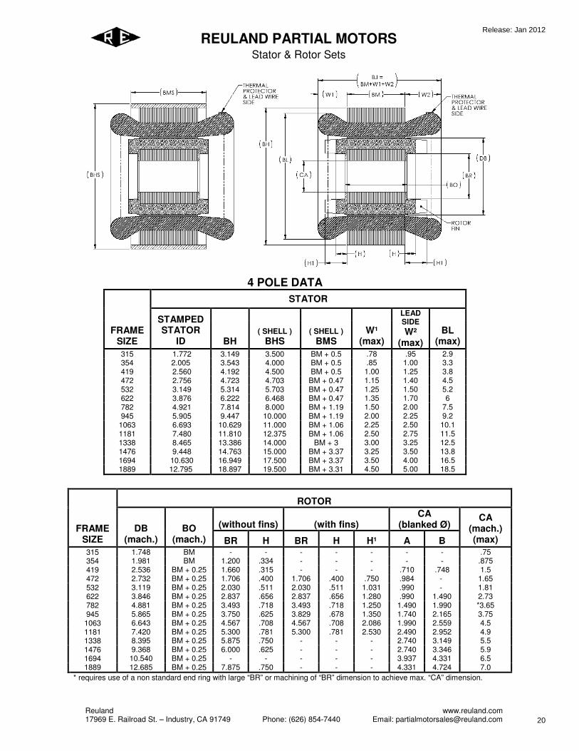
4 POLE DATA
STATOR
FRAME
SIZE
STAMPED
STATOR
ID BH
( SHELL )
BHS
( SHELL )
BMS
W¹
(max)
LEAD
SIDE
W²
(max)
BL
(max)
315 1.772 3.149 3.500 BM + 0.5 .78 .95 2.9 354 2.005 3.543 4.000 BM + 0.5 .85 1.00 3.3 419 2.560 4.192 4.500 BM + 0.5 1.00 1.25 3.8 472 2.756 4.723 4.703 BM + 0.47 1.15 1.40 4.5 532 3.149 5.314 5.703 BM + 0.47 1.25 1.50 5.2 622 3.876 6.222 6.468 BM + 0.47 1.35 1.70 6 782 4.921 7.814 8.000 BM + 1.19 1.50 2.00 7.5 945 5.905 9.447 10.000 BM + 1.19 2.00 2.25 9.2
1063 6.693 10.629 11.000 BM + 1.06 2.25 2.50 10.1 1181 7.480 11.810 12.375 BM + 1.06 2.50 2.75 11.5 1338 8.465 13.386 14.000 BM + 3 3.00 3.25 12.5 1476 9.448 14.763 15.000 BM + 3.37 3.25 3.50 13.8 1694 10.630 16.949 17.500 BM + 3.37 3.50 4.00 16.5 1889 12.795 18.897 19.500 BM + 3.31 4.50 5.00 18.5
ROTOR
(without fins) (with fins)
CA
(blanked Ø) FRAME
SIZE
DB
(mach.)
BO
(mach.) BR H BR H H¹ A B
CA
(mach.)
(max)
315 1.748 BM - - - - - - - .75 354 1.981 BM 1.200 .334 - - - - - .875 419 2.536 BM + 0.25 1.660 .315 - - - .710 .748 1.5 472 2.732 BM + 0.25 1.706 .400 1.706 .400 .750 .984 - 1.65 532 3.119 BM + 0.25 2.030 .511 2.030 .511 1.031 .990 - 1.81 622 3.846 BM + 0.25 2.837 .656 2.837 .656 1.280 .990 1.490 2.73 782 4.881 BM + 0.25 3.493 .718 3.493 .718 1.250 1.490 1.990 *3.65 945 5.865 BM + 0.25 3.750 .625 3.829 .678 1.350 1.740 2.165 3.75 1063 6.643 BM + 0.25 4.567 .708 4.567 .708 2.086 1.990 2.559 4.5 1181 7.420 BM + 0.25 5.300 .781 5.300 .781 2.530 2.490 2.952 4.9 1338 8.395 BM + 0.25 5.875 .750 - - - 2.740 3.149 5.5 1476 9.368 BM + 0.25 6.000 .625 - - - 2.740 3.346 5.9 1694 10.540 BM + 0.25 - - - - - 3.937 4.331 6.5 1889 12.685 BM + 0.25 7.875 .750 - - - 4.331 4.724 7.0
* requires use of a non standard end ring with large “BR” or machining of “BR” dimension to achieve max. “CA” dimension.
Release: Jan 2012
20

Reuland www.reuland.com 17969 E. Railroad St. – Industry, CA 91749 Phone: (626) 854-7440 Email: [email protected]
REULAND PARTIAL MOTORS
Stator & Rotor Sets
TOLERANCE
w/shell w/out shell
±.250 BJ ±.250 - BH +0.003/-0.002
0.000/-0.002 BHS - - BM ±.060
0.000/-0.030 BMS - ±.030 BO ±.030
±.200 BL ±.200 0.000/-0.001 CA 0.000/-0.001
±.025 BR ±.025 ±.200 BP ±.200 ±.001 DB* ±.001
* "DB" Customer to finish turn rotor to specified diameter and balance.
Reuland may finish-turn upon request.
NOTES
1. Straight bore without keyway is standard. 2. Maximum bore shown is for standard die cast rotors without keyway; with keyway,
reduce by keyway depth. Larger bores may be available using die cast rotors with non standard laminations and/or fabricated rotor construction. (Consult factory.)
3. Blanked bore is as die punched. 4. Speeds higher than the base 60 Hz rating may limit the maximum bore. 5. Standard lead length is 3 feet.
SENSORS
VALUE OPTION
1 ( 1 ) 150°C N.C. THERMAL SWITCH
2 ( 3 ) 150°C N.C. THERMAL SWITCH, 1 PER PHASE
3 ( 1 ) 100 ohm PLATINUM RTD
4 ( 1 ) type "J" THERMOCOUPLE
5 ( 1 ) type "K" THERMOCOUPLE
6 ( 1 ) type "T" THERMOCOUPLE
7 ( 1 ) PTC THERMISTOR
8 ( 1 ) NTC THERMISTOR
Z OTHER
Release: Jan 2012
21
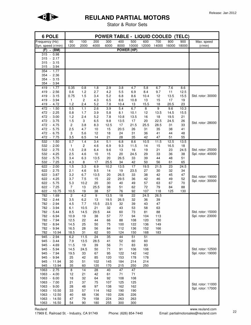
60 100 200 300 400 500 600 700 800 900 Max. speed
1200 2000 4000 6000 8000 10000 12000 14000 16000 18000 (r/min)
(F) - (BM)
315 - 0.98
315 - 2.17
315 - 3.15
315 - 3.94
354 - 1.77
354 - 2.36
354 - 3.15
354 - 3.94
419 - 1.77 0.35 0.8 1.8 2.9 3.8 4.7 5.8 6.7 7.6 8.6
419 - 2.56 0.6 1.2 2.7 4.2 5.5 6.9 8.4 9.7 11 12.5
419 - 3.15 0.75 1.5 3.4 5.2 6.8 8.6 10.4 12 13.5 15.5
419 - 3.94 1 2 4.3 6.5 8.6 10.8 13 15 17 19
419 - 4.72 1.2 2.4 5.2 7.8 10.4 13 15.5 18 20.5 23
472 - 1.50 0.5 1.1 2.6 3.9 5.4 6.7 8 9 9.6 10.3
472 - 2.25 0.8 1.7 3.9 5.8 8.1 10.1 12 13.5 14.5 15.5
472 - 3.00 1.2 2.4 5.2 7.8 10.8 13.5 16 18 19.5 21
472 - 3.75 1.5 3 6.5 9.8 13.5 17 20 22.5 24.5 26
472 - 4.75 2 3.8 8.3 12.5 17 21.5 25.5 28.5 31 33
472 - 5.75 2.5 4.7 10 15 20.5 26 31 35 38 41
472 - 6.75 3 5.6 12 18 24 31 36 41 44 48
472 - 7.75 3.5 6.5 14 21 28 35 42 47 51 55
532 - 1.50 0.7 1.4 3.4 5.1 6.8 8.6 10.5 11.5 12.5 13.5
532 - 2.00 1 2 4.6 6.9 9.3 11.5 14 15 16.5 18
532 - 2.75 1.5 2.8 6.4 9.6 13 16 19 21 23 24.5
532 - 4.25 2.5 4.6 10 15 20 24.5 29 33 36 38
532 - 5.75 3.4 6.3 13.5 20 26.5 33 39 44 48 51
532 - 7.25 4.3 8 17 25.5 34 42 50 56 61 65
622 - 2.00 1.5 3.3 6.9 10.2 13.5 17 19.5 21.5 23 24.5
622 - 2.75 2.1 4.6 9.5 14 19 23.5 27 30 32 34
622 - 3.87 3.2 6.7 13.5 20 26.5 33 38 42 45 47
622 - 4.25 3.7 7.5 15 22 29.5 36 42 46 49 52
622 - 5.75 5.3 10.2 20 30 40 49 57 63 67 70
622 - 7.25 7 13 25.5 38 51 62 72 79 84 88
622 - 10.75 10.5 19 38 57 76 92 107 118 125 130
782 - 1.69 2 4.2 9 13.5 18 22 24.5 26.5
782 - 2.44 3.5 6.2 13 19.5 26.5 32 36 39
782 - 2.94 4.5 7.7 15.5 23.5 32 39 43 47
782 - 3.94 6.1 10.5 21 32 43 53 58 63
782 - 5.44 8.5 14.5 29.5 44 60 73 81 88
782 - 6.94 10.9 19 38 57 77 94 104 113
782 - 7.94 12.5 22 44 66 88 108 120 130
782 - 8.94 14.5 25 50 75 100 122 136 149
782 - 9.94 16.5 28 56 84 112 136 152 166
782 - 10.94 18.5 31 62 93 124 150 168 183
945 - 2.94 6.2 11.5 24 35 44 51 51
945 - 3.44 7.9 13.5 28.5 41 52 60 60
945 - 4.69 11.5 19 39 56 71 83 83
945 - 5.94 14.5 24.5 50 71 91 106 106
945 - 7.94 19.5 33 67 95 122 142 142
945 - 9.94 25 42 85 120 153 178 178
945 - 11.94 30 51 102 145 184 214 214
945 - 13.94 35 60 120 170 215 250 250
1063 - 2.75 8 14 28 40 47 47
1063 - 4.00 12 21 42 61 71 71
1063 - 6.00 18 32 64 92 108 108
1063 - 7.00 21 37 75 107 125 125
1063 - 9.00 28 48 97 138 162 162
1063 - 10.50 33 57 114 162 190 190
1063 - 12.50 40 68 136 193 226 226
1063 - 14.50 47 79 158 224 263 263
1063 - 16.50 54 90 180 255 300 300
REULAND PARTIAL MOTORS
Stator & Rotor Sets
Frequency (Hz)
Syn. speed (r/min)
6 POLE POWER TABLE - LIQUID COOLED (TELC)
Std. rotor: 15000
Spl. rotor: 23000
Std. rotor: 12500
Spl. rotor: 19000
Std. rotor: 30000
Std. rotor: 28000
POWER (HP)
Std. rotor: 11000
Spl. rotor: 17000
Std. rotor: 25000
Spl. rotor: 40000
Std. rotor: 19000
Spl. rotor: 30000
Reuland
17969 E. Railroad St. - Industry, CA 91749 Phone: (626) 854-7440
www.reuland.com
Email: [email protected]
Release: Jan 2012
22

60 100 200 300 400 500 600 700 800 900 Max. speed
1200 2000 4000 6000 8000 10000 12000 14000 16000 18000 (r/min)
(F) - (BM)
REULAND PARTIAL MOTORS
Stator & Rotor Sets
Frequency (Hz)
Syn. speed (r/min)
6 POLE POWER TABLE - LIQUID COOLED (TELC)
POWER (HP)
1181 - 5.56 22 36 75 104 104 104
1181 - 7.06 28 46 95 132 132 132
1181 - 9.06 36 60 122 170 170 170
1181 - 10.06 40 67 136 189 189 189
1181 - 11.06 44 74 150 208 208 208
1181 - 13.06 53 88 177 246 246 246
1181 - 15.06 62 102 204 284 284 284
1181 - 17.06 70 116 232 322 322 322
1181 - 19.06 78 130 260 360 360 360
1338 - 5.00 28 47 82 109 109
1338 - 7.50 42 71 123 163 163
1338 - 9.50 54 90 156 207 207
1338 - 12.00 68 114 197 262 262
1338 - 14.50 82 138 238 317 317
1338 - 17.00 96 162 279 372 372
1338 - 19.00 108 181 312 416 416
1338 - 21.00 120 200 345 460 460
1476 - 4.63 37 60 90 110 110
1476 - 5.63 45 74 111 136 136
1476 - 7.13 57 94 141 173 173
1476 - 9.13 73 122 182 223 223
1476 - 11.13 89 149 223 273 273
1476 - 13.13 105 177 265 324 324
1476 - 16.13 130 218 327 400 400
1476 - 19.13 155 259 389 475 475
1476 - 22.13 180 300 450 550 550
1694 - 5.63 63 106 174 174 174
1694 - 7.13 80 135 221 221 221
1694 - 9.13 103 174 283 283 283
1694 - 12.13 137 231 376 376 376
1694 - 15.13 171 288 469 469 469
1694 - 18.13 205 345 562 562 562
1694 - 21.13 240 402 656 656 656
1694 - 24.13 275 460 750 750 750
1889 - 7.19 106 177 300 300
1889 - 9.19 135 226 383 383
1889 - 10.19 150 251 425 425
1889 - 11.19 165 276 467 467
1889 - 13.19 195 326 552 552
1889 - 15.19 225 376 636 636
1889 - 17.19 255 425 720 720
1889 - 20.19 300 500 847 847
1889 - 23.19 345 575 974 974
1889 - 26.19 390 650 1100 1100
Std. rotor: 7500
Spl. rotor: 10000
Std. rotor: 6000
Spl. rotor: 8500
Std. rotor: 10000
Spl. rotor: 15000
Std. rotor: 9000
Spl. rotor: 13000
Std. rotor: 8000
Spl. rotor: 11000
NOTES:
1. FRAME SIZE: (F) dimension represents the stator diameter (BH), in inches having a decimal two places to the left (Ex: F
of 1181 = BH of 11.81). The (BM) dimension represents the stator core-length in inches.
2. POWER: The horsepower values represent the maximum continuous duty power allowable at a given speed using
standard rotor of a given frame with adequate liquid cooling. For application sizing, the frame is selected based on the
power tables above and the windings are designed to meet the individual power requirements of the application. TELC
maximum power ratings are based on winding temeprature rise of 130°C. Consult factory for performance using special
rotor.
3. MAXIMUM SPEED: For standard rotor, this is the maximum allowable speed using die-cast rotor construction and
standard rotor bores. For special rotor, this is the maximum allowable speed using die-cast rotor construction with
encapsulation and standard rotor bores.
Reuland
17969 E. Railroad St. - Industry, CA 91749 Phone: (626) 854-7440
www.reuland.com
Email: [email protected]
Release: Jan 2012
23
60 100 200 300 400 500 600 700 800 900 Max. speed
1200 2000 4000 6000 8000 10000 12000 14000 16000 18000 (r/min)
(F) - (BM)
315 - 0.98
315 - 2.17
315 - 3.15
315 - 3.94
354 - 1.77
354 - 2.36
354 - 3.15
354 - 3.94
419 - 1.77 0.19 0.26 0.49 0.6 0.65 0.61 0.57 0.52 0.49 0.45
419 - 2.56 0.35 0.49 0.88 1.05 1.2 1.1 1.05 0.95 0.88 0.8
419 - 3.15 0.49 0.7 1.2 1.5 1.7 1.6 1.5 1.4 1.3 1.2
419 - 3.94 0.7 0.96 1.7 2.1 2.3 2.2 2.1 1.9 1.7 1.6
419 - 4.72 0.88 1.2 2.3 2.7 3 2.9 2.7 2.5 2.3 2.1
472 - 1.50 0.26 0.42 0.7 0.78 0.88 0.88 0.78 0.7 0.61 0.52
472 - 2.25 0.42 0.65 1.1 1.4 1.6 1.5 1.3 1.2 1.05 0.88
472 - 3.00 0.61 0.93 1.5 1.9 2.3 2.1 1.9 1.8 1.6 1.4
472 - 3.75 0.78 1.2 1.9 2.5 2.9 2.7 2.4 2.3 2 1.8
472 - 4.75 1.05 1.6 2.6 3.3 3.9 3.5 3.2 2.9 2.6 2.3
472 - 5.75 1.3 1.9 3.2 4 4.7 4.2 3.9 3.5 3.2 2.8
472 - 6.75 1.6 2.5 4.2 5.1 5.8 5.3 4.9 4.4 4 3.5
472 - 7.75 1.9 3 5.1 6.3 7 6.5 6 5.4 4.9 4.4
532 - 1.50 0.52 0.7 1.05 1.4 1.6 1.4 1.3 1.2 1.05 0.9
532 - 2.00 0.7 0.96 1.5 1.9 2.1 1.9 1.8 1.6 1.4 1.2
532 - 2.75 0.98 1.3 2.1 2.6 2.9 2.6 2.5 2.3 2.1 1.8
532 - 4.25 1.6 2.1 3.3 4.2 4.7 4.4 4 3.7 3.3 3
532 - 5.75 2.2 3 4.9 6 6.7 6.2 5.8 5.3 4.7 4.2
532 - 7.25 2.8 3.9 6.2 7.5 8.4 7.9 7.4 6.7 6 5.3
622 - 2.00 0.96 1.2 1.9 2.3 2.3 2.1 1.9 1.8 1.6 1.3
622 - 2.75 1.4 1.9 3 3.5 3.5 3.2 2.8 2.5 2.3 1.9
622 - 3.87 2.1 3 4.7 5.3 5.3 4.7 4.2 3.9 3.3 2.8
622 - 4.25 2.5 3.3 5.3 6.1 6.1 5.4 4.9 4.4 3.9 3.3
622 - 5.75 3.5 4.7 7.7 8.8 8.8 7.9 7.2 6.3 5.6 4.7
622 - 7.25 4.7 6.5 10.3 11.5 11.5 10.6 9.6 8.6 7.5 6.5
622 - 10.75 7 9.5 15 17.5 17.5 16 14.5 13 11 9.6
782 - 1.69 1.2 1.8 2.8 3 2.8 2.6 2.3 2.1
782 - 2.44 2.1 3.2 5.1 5.1 4.7 4.4 3.9 3.5
782 - 2.94 2.8 4 6.5 6.7 6.3 5.8 5.3 4.7
782 - 3.94 3.9 5.6 8.8 9.1 8.6 7.7 7 6.3
782 - 5.44 5.4 7.9 12.5 13 12 11 10 9.1
782 - 6.94 7 10 16 17 16 14 13 11.5
782 - 7.94 8.1 11.5 18.5 19.5 18.5 16.5 15 13.5
782 - 8.94 9.3 13.5 21 22.5 21 19 17 15.5
782 - 9.94 10.7 15.5 24.5 26 24.5 22 20 18
782 - 10.94 12 17.5 28 30 28 25.5 23 21
945 - 2.94 3.8 5.5 8.7 7.8 7.2 6.3 5.5
945 - 3.44 5 7.2 11.5 10.5 9.5 8.2 7.2
945 - 4.69 7.4 10.6 16.5 15.5 14 12.5 10.6
945 - 5.94 9.3 13.5 21 19.5 17.5 15.5 13.5
945 - 7.94 12.5 18 27.5 26 24 20.5 17.5
945 - 9.94 15.5 23 35 32 29.5 25.5 22
945 - 11.94 18.5 27.5 44 40 36 31 26.5
945 - 13.94 22 32 51 47 42 36 31
1063 - 2.75 4.6 6.6 9.6 8.8 7.8 7
1063 - 4.00 7 10.2 14.5 13 12 10.6
1063 - 6.00 10.6 15 22 20 18 16
1063 - 7.00 12.5 18 26 24 21.5 19
1063 - 9.00 16.5 24 34 31 28 25
1063 - 10.50 19.5 28 40 37 33 30
1063 - 12.50 24 34 49 44 40 36
1063 - 14.50 28 40 58 52 47 42
1063 - 16.50 32 46 66 60 54 48
REULAND PARTIAL MOTORS
Stator & Rotor Sets
POWER (HP)
Std. rotor: 30000
Std. rotor: 28000
Std. rotor: 11000
Spl. rotor: 17000
Std. rotor: 25000
Spl. rotor: 40000
Std. rotor: 19000
Spl. rotor: 30000
Std. rotor: 15000
Spl. rotor: 23000
Std. rotor: 12500
Spl. rotor: 19000
Frequency (Hz)
Syn. speed (r/min)
6 POLE POWER TABLE - FAN COOLED (TEFC)
Reuland
17969 E. Railroad St. - Industry, CA 91749 Phone: (626) 854-7440
www.reuland.com
Email: [email protected]
Release: Jan 2012
24

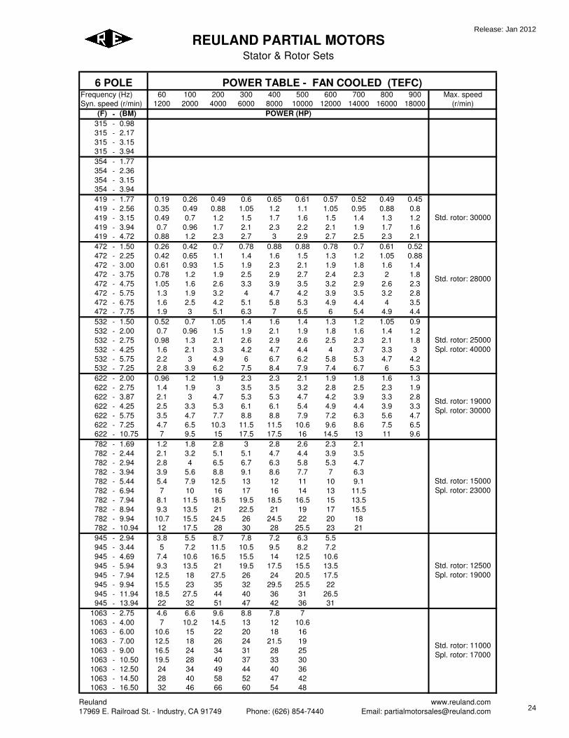
60 100 200 300 400 500 600 700 800 900 Max. speed
1200 2000 4000 6000 8000 10000 12000 14000 16000 18000 (r/min)
(F) - (BM)
REULAND PARTIAL MOTORS
Stator & Rotor Sets
POWER (HP)
Frequency (Hz)
Syn. speed (r/min)
6 POLE POWER TABLE - FAN COOLED (TEFC)
1181 - 5.56 13.5 20 31 28 24 19.5
1181 - 7.06 17.5 25.5 40 36 31 25
1181 - 9.06 22.5 33 51 46 40 32
1181 - 10.06 24.5 36 56 51 44 36
1181 - 11.06 27 40 62 56 49 40
1181 - 13.06 32 48 74 68 58 48
1181 - 15.06 37 55 86 78 66 56
1181 - 17.06 42 62 100 90 78 64
1181 - 19.06 47 70 110 100 86 71
1338 - 5.00 18.5 32 35 31 27
1338 - 7.50 28 48 52 47 41
1338 - 9.50 35 60 66 60 52
1338 - 12.00 44 76 82 75 66
1338 - 14.50 54 90 100 90 80
1338 - 17.00 64 108 118 108 94
1338 - 19.00 72 122 134 122 108
1338 - 21.00 80 136 150 136 120
1476 - 4.63 22.5 37 41 38 33
1476 - 5.63 27.5 45 50 46 40
1476 - 7.13 35 57 63 58 50
1476 - 9.13 44 72 80 74 63
1476 - 11.13 54 88 99 90 78
1476 - 13.13 63 105 118 107 92
1476 - 16.13 78 130 143 131 113
1476 - 19.13 92 155 172 158 137
1476 - 22.13 107 181 200 183 160
1694 - 5.63 38 64 64 58 49
1694 - 7.13 48 81 81 72 62
1694 - 9.13 61 104 104 92 79
1694 - 12.13 81 138 138 122 106
1694 - 15.13 103 175 175 154 133
1694 - 18.13 124 209 209 186 159
1694 - 21.13 145 244 244 216 186
1694 - 24.13 166 281 281 248 214
1889 - 7.19 81 138 138 120
1889 - 9.19 105 177 177 156
1889 - 10.19 117 195 195 174
1889 - 11.19 129 216 216 192
1889 - 13.19 150 252 252 222
1889 - 15.19 174 294 294 258
1889 - 17.19 198 333 333 294
1889 - 20.19 234 393 393 348
1889 - 23.19 267 450 450 396
1889 - 26.19 303 510 510 450
Std. rotor: 7500
Spl. rotor: 10000
Std. rotor: 6000
Spl. rotor: 8500
Std. rotor: 10000
Spl. rotor: 15000
Std. rotor: 9000
Spl. rotor: 13000
Std. rotor: 8000
Spl. rotor: 11000
NOTES:
1. FRAME SIZE: (F) dimension represents the stator diameter (BH), in inches having a decimal two places to the left (Ex: F
of 1181 = BH of 11.81). The (BM) dimension represents the stator core-length in inches.
2. POWER: The horsepower values represent the maximum continuous duty power allowable at a given speed using
standard rotor of a given frame with adequate air cooling. For application sizing, the frame is selected based on the power
tables above and the windings are designed to meet the individual power requirements of the application. TEFC maximum
power ratings are based on winding temeprature rise of 80°C. Consult factory for performance using special rotor.
3. MAXIMUM SPEED: For standard rotor, this is the maximum allowable speed using die-cast rotor construction and
standard rotor bores. For special rotor, this is the maximum allowable speed using die-cast rotor construction with
encapsulation and standard rotor bores.
Reuland
17969 E. Railroad St. - Industry, CA 91749 Phone: (626) 854-7440
www.reuland.com
Email: [email protected]
Release: Jan 2012
25

60 100 200 300 400 500 600 700 800 900 Max. speed
1200 2000 4000 6000 8000 10000 12000 14000 16000 18000 (r/min)
(F) - (BM)
315 - 0.98
315 - 2.17
315 - 3.15
315 - 3.94
354 - 1.77
354 - 2.36
354 - 3.15
354 - 3.94
419 - 1.77 0.11 0.15 0.28 0.34 0.37 0.35 0.33 0.3 0.28 0.26
419 - 2.56 0.2 0.28 0.5 0.6 0.7 0.65 0.6 0.54 0.5 0.46
419 - 3.15 0.28 0.4 0.7 0.85 1 0.92 0.85 0.79 0.72 0.67
419 - 3.94 0.4 0.55 1 1.2 1.3 1.2 1.1 1.05 1 0.95
419 - 4.72 0.5 0.7 1.3 1.5 1.7 1.6 1.5 1.4 1.3 1.2
472 - 1.50 0.15 0.24 0.4 0.45 0.5 0.5 0.45 0.4 0.35 0.3
472 - 2.25 0.24 0.37 0.64 0.78 0.9 0.82 0.75 0.67 0.6 0.5
472 - 3.00 0.35 0.55 0.95 1.1 1.3 1.2 1.1 1 0.9 0.8
472 - 3.75 0.45 0.7 1.2 1.4 1.6 1.5 1.4 1.2 1.1 1
472 - 4.75 0.6 0.9 1.5 1.9 2.2 2 1.8 1.6 1.5 1.3
472 - 5.75 0.72 1.1 1.8 2.3 2.7 2.4 2.2 2 1.8 1.6
472 - 6.75 0.9 1.4 2.4 2.9 3.3 3 2.8 2.5 2.3 2
472 - 7.75 1.1 1.7 2.9 3.6 4 3.7 3.4 3.1 2.8 2.5
532 - 1.50 0.3 0.4 0.6 0.79 0.9 0.82 0.75 0.68 0.6 0.53
532 - 2.00 0.4 0.55 0.85 1.1 1.2 1.1 1 0.9 0.8 0.7
532 - 2.75 0.55 0.76 1.2 1.5 1.7 1.5 1.4 1.3 1.2 1
532 - 4.25 0.9 1.2 1.9 2.4 2.7 2.5 2.3 2.1 1.9 1.7
532 - 5.75 1.2 1.7 2.8 3.4 3.8 3.5 3.3 3 2.7 2.4
532 - 7.25 1.6 2.2 3.5 4.3 4.8 4.5 4.2 3.8 3.4 3
622 - 2.00 0.55 0.7 1.1 1.3 1.3 1.2 1.1 1 0.9 0.75
622 - 2.75 0.8 1.1 1.7 2 2 1.8 1.6 1.4 1.3 1.1
622 - 3.87 1.2 1.7 2.7 3 3 2.7 2.4 2.2 1.9 1.6
622 - 4.25 1.4 1.9 3 3.5 3.5 3.1 2.8 2.5 2.2 1.9
622 - 5.75 2 2.7 4.4 5 5 4.5 4.1 3.6 3.2 2.7
622 - 7.25 2.7 3.7 5.9 6.7 6.7 6.1 5.5 4.9 4.3 3.7
622 - 10.75 4 5.4 8.7 10 10 9.1 8.2 7.3 6.4 5.5
782 - 1.69 0.7 1 1.6 1.7 1.6 1.5 1.3 1.2
782 - 2.44 1.2 1.8 2.9 2.9 2.7 2.5 2.2 2
782 - 2.94 1.6 2.3 3.7 3.8 3.6 3.3 3 2.7
782 - 3.94 2.2 3.2 5 5.2 4.9 4.4 4 3.6
782 - 5.44 3.1 4.5 7.2 7.5 7 6.3 5.7 5.2
782 - 6.94 4 5.8 9.3 9.6 9.1 8.1 7.4 6.8
782 - 7.94 4.6 6.6 10.6 11 10.5 9.4 8.5 7.8
782 - 8.94 5.3 7.7 12 13 12 10.8 9.8 9
782 - 9.94 6.1 8.8 14 15 14 12.5 11 10
782 - 10.94 7 10 16 17 16 14.5 13 12
945 - 2.94 2 2.9 4.6 4.1 3.8 3.3 2.9
945 - 3.44 2.6 3.8 6 5.4 5 4.3 3.8
945 - 4.69 3.9 5.6 8.8 8.1 7.4 6.5 5.6
945 - 5.94 4.9 7.1 11 10.2 9.3 8.2 7.1
945 - 7.94 6.5 9.3 14.5 13.5 12.5 10.8 9.3
945 - 9.94 8.1 12 18.5 17 15.5 13.5 11.5
945 - 11.94 9.8 14.5 23 21 19 16.5 14
945 - 13.94 11.5 17 27 24.5 22 19 16.5
1063 - 2.75 2.3 3.3 4.8 4.4 3.9 3.5
1063 - 4.00 3.5 5.1 7.3 6.6 6 5.3
1063 - 6.00 5.3 7.6 11 9.9 8.9 8
1063 - 7.00 6.2 9 13 12 10.8 9.5
1063 - 9.00 8.3 12 17 15.5 14 12.5
1063 - 10.50 9.7 14 20 18.5 16.5 15
1063 - 12.50 12 17 24.5 22.5 20 18
1063 - 14.50 14 20 29 26 23.5 21
1063 - 16.50 16 23 33 30 27 24
REULAND PARTIAL MOTORS
Stator & Rotor Sets
Frequency (Hz)
Syn. speed (r/min)
6 POLE POWER TABLE - NON VENTED (TENV)
Std. rotor: 15000
Spl. rotor: 23000
Std. rotor: 12500
Spl. rotor: 19000
Std. rotor: 30000
Std. rotor: 28000
POWER (HP)
Std. rotor: 11000
Spl. rotor: 17000
Std. rotor: 25000
Spl. rotor: 40000
Std. rotor: 19000
Spl. rotor: 30000
Reuland
17969 E. Railroad St. - Industry, CA 91749 Phone: (626) 854-7440
www.reuland.com
Email: [email protected]
Release: Jan 2012
26

60 100 200 300 400 500 600 700 800 900 Max. speed
1200 2000 4000 6000 8000 10000 12000 14000 16000 18000 (r/min)
(F) - (BM)
REULAND PARTIAL MOTORS
Stator & Rotor Sets
Frequency (Hz)
Syn. speed (r/min)
6 POLE POWER TABLE - NON VENTED (TENV)
POWER (HP)
1181 - 5.56 6.7 10 15.5 14 12 9.8
1181 - 7.06 8.5 12.5 20 18 15.5 12.5
1181 - 9.06 10.8 16 25.5 23 19.5 16
1181 - 10.06 12 18 28 25 22 18
1181 - 11.06 13.5 20 31 28 24.5 20
1181 - 13.06 16.5 24 37 34 29 24
1181 - 15.06 19 27.5 43 39 33 28
1181 - 17.06 21.5 31 50 45 39 32
1181 - 19.06 24 35 55 50 43 36
1338 - 5.00 9.3 16 17.5 15.5 13.5
1338 - 7.50 14 24 26 23.5 20.5
1338 - 9.50 17.5 30 33 30 26
1338 - 12.00 22 38 41 37 33
1338 - 14.50 27 45 50 45 40
1338 - 17.00 32 54 59 54 47
1338 - 19.00 36 61 67 61 54
1338 - 21.00 40 68 75 68 60
1476 - 4.63 10.8 18 20 18 15.5
1476 - 5.63 13 21.5 24 22 19
1476 - 7.13 16.5 27 30 27.5 24
1476 - 9.13 21 34 38 35 30
1476 - 11.13 25.5 42 47 43 37
1476 - 13.13 30 50 56 51 44
1476 - 16.13 37 62 68 62 54
1476 - 19.13 44 74 82 75 65
1476 - 22.13 51 86 95 87 76
1694 - 5.63 16.5 28 28 25 21.5
1694 - 7.13 21 35 35 31 27
1694 - 9.13 26.5 45 45 40 34
1694 - 12.13 35 60 60 53 46
1694 - 15.13 45 76 76 67 58
1694 - 18.13 54 91 91 81 69
1694 - 21.13 63 106 106 94 81
1694 - 24.13 72 122 122 108 93
1889 - 7.19 27 46 46 40
1889 - 9.19 35 59 59 52
1889 - 10.19 39 65 65 58
1889 - 11.19 43 72 72 64
1889 - 13.19 50 84 84 74
1889 - 15.19 58 98 98 86
1889 - 17.19 66 111 111 98
1889 - 20.19 78 131 131 116
1889 - 23.19 89 150 150 132
1889 - 26.19 101 170 170 150
Std. rotor: 7500
Spl. rotor: 10000
Std. rotor: 6000
Spl. rotor: 8500
Std. rotor: 10000
Spl. rotor: 15000
Std. rotor: 9000
Spl. rotor: 13000
Std. rotor: 8000
Spl. rotor: 11000
NOTES:
1. FRAME SIZE: (F) dimension represents the stator diameter (BH), in inches having a decimal two places to the left (Ex: F
of 1181 = BH of 11.81). The (BM) dimension represents the stator core-length in inches.
2. POWER: The horsepower values represent the maximum continuous duty power allowable at a given speed using
standard rotor of a given frame. For application sizing, the frame is selected based on the power tables above and the
windings are designed to meet the individual power requirements of the application. TENV maximum power ratings are
based on winding temeprature rise of 80°C. Consult factory for performance using special rotor.
3. MAXIMUM SPEED: For standard rotor, this is the maximum allowable speed using die-cast rotor construction and
standard rotor bores. For special rotor, this is the maximum allowable speed using die-cast rotor construction with
encapsulation and standard rotor bores.
Reuland
17969 E. Railroad St. - Industry, CA 91749 Phone: (626) 854-7440
www.reuland.com
Email: [email protected]
Release: Jan 2012
27
Reuland www.reuland.com 17969 E. Railroad St. – Industry, CA 91749 Phone: (626) 854-7440 Email: [email protected]
REULAND PARTIAL MOTORS
Stator & Rotor Sets
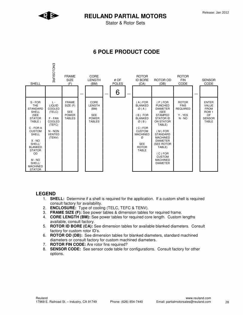
6 POLE PRODUCT CODE
SHELL
EN
CLO
SU
RE
FRAME SIZE (F)
CORE LENGTH
(BM) # OF
POLES
ROTOR ID BORE
(CA) ROTOR OD
(DB)
ROTOR FIN
CODE SENSOR
CODE
_
_ 6 _
_
S - FOR
THE STANDARD
SHELL (SEE
STATOR TABLE )
C - FOR A CUSTOM
SHELL
X - NO SHELL/
BLANKED STATOR
OD
M - NO SHELL/
MACHINED STATOR
L -
LIQUID COOLED (TELC)
F - FAN
COOLED (TEFC)
N - NON VENTED (TENV)
FRAME SIZE (F)
SEE
POWER TABLES
CORE
LENGTH (BM)
SEE
POWER TABLES
( A ) FOR BLANKED
Ø ( A )
( B ) FOR BLANKED
Ø ( B )
( C ) FOR CUSTOM
MACHINED Ø
SEE ROTOR TABLE
( P ) FOR
PUNCHED DIAMETER
(SEE STAMPED STATOR ID ON STATOR
TABLE)
( M ) FOR STANDARD MACHINED DIAMETER
(SEE ROTOR TABLE)
( C ) FOR CUSTOM
MACHINED DIAMETER
ROTOR
FINS REQUIRED
Y - YES N - NO
ENTER VALUE FROM ROW 1
OF SENSOR TABLE
LEGEND
1. SHELL: Determine if a shell is required for the application. If a custom shell is required consult factory for availability.
2. ENCLOSURE: Type of cooling (TELC, TEFC & TENV). 3. FRAME SIZE (F): See power tables & dimension tables for required frame. 4. CORE LENGTH (BM): See power tables for required core length. Custom lengths
available, consult factory. 5. ROTOR ID BORE (CA): See dimension tables for available blanked diameters. Consult
factory for custom rotor ID’s. 6. ROTOR OD (DB): See dimension tables for blanked diameters, standard machined
diameters or consult factory for custom machined diameters. 7. ROTOR FIN CODE: Are rotor fins required? 8. SENSOR CODE: See sensor code table for configurations. Consult factory for other
options.
Release: Jan 2012
28
Reuland www.reuland.com 17969 E. Railroad St. – Industry, CA 91749 Phone: (626) 854-7440 Email: [email protected]
REULAND PARTIAL MOTORS
Stator & Rotor Sets
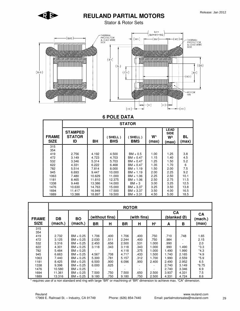
6 POLE DATA
STATOR
FRAME
SIZE
STAMPED
STATOR
ID BH
( SHELL )
BHS
( SHELL )
BMS
W¹
(max)
LEAD
SIDE
W²
(max)
BL
(max)
315 354 419 2.756 4.192 4.500 BM + 0.5 1.00 1.25 3.8 472 3.149 4.723 4.703 BM + 0.47 1.15 1.40 4.5 532 3.346 5.314 5.703 BM + 0.47 1.25 1.50 5.2 622 4.331 6.222 6.468 BM + 0.47 1.35 1.70 6 782 5.514 7.814 8.000 BM + 1.19 1.50 2.00 7.5 945 6.693 9.447 10.000 BM + 1.19 2.00 2.25 9.2
1063 7.480 10.629 11.000 BM + 1.06 2.25 2.50 10.1 1181 8.465 11.810 12.375 BM + 1.06 2.50 2.75 11.5 1338 9.448 13.386 14.000 BM + 3 3.00 3.25 12.5 1476 10.630 14.763 15.000 BM + 3.37 3.25 3.50 13.8 1694 11.417 16.949 17.500 BM + 3.37 3.50 4.00 16.5 1889 13.386 18.897 19.500 BM + 3.31 4.50 5.00 18.5
ROTOR
(without fins) (with fins)
CA
(blanked Ø) FRAME
SIZE
DB
(mach.)
BO
(mach.) BR H BR H H¹ A B
CA
(mach.)
(max)
315 354 419 2.732 BM + 0.25 1.706 .400 1.706 .400 .750 .710 .748 1.65 472 3.125 BM + 0.25 2.030 .511 2.244 .400 .750 .984 - 2.15 532 3.316 BM + 0.25 2.450 .656 2.500 .531 1.000 .990 - 2.0 622 4.301 BM + 0.25 3.118 .343 3.118 .343 1.000 .990 1.490 *3.3 782 5.484 BM + 0.25 - - 4.118 .375 1.000 1.490 1.990 *4.3 945 6.663 BM + 0.25 4.567 .708 4.717 .433 1.500 1.740 2.165 *4.9 1063 7.440 BM + 0.25 5.300 .781 5.157 .312 1.700 1.990 2.559 *5.9 1181 8.425 BM + 0.25 6.500 .900 6.096 .900 2.400 2.490 2.952 6.5 1338 9.398 BM + 0.25 6.000 .625 - - - 2.740 3.149 *6.75 1476 10.580 BM + 0.25 - - - - - 2.740 3.346 6.9 1694 11.361 BM + 0.25 7.500 .750 7.500 .650 2.500 3.937 4.331 7.5 1889 13.316 BM + 0.25 9.180 .750 9.180 .750 2.500 4.331 4.724 8.6
* requires use of a non standard end ring with large “BR” or machining of “BR” dimension to achieve max. “CA” dimension.
Release: Jan 2012
29

Reuland www.reuland.com 17969 E. Railroad St. – Industry, CA 91749 Phone: (626) 854-7440 Email: [email protected]
REULAND PARTIAL MOTORS
Stator & Rotor Sets
TOLERANCE
w/shell w/out shell
±.250 BJ ±.250 - BH +0.003/-0.002
0.000/-0.002 BHS - - BM ±.060
0.000/-0.030 BMS - ±.030 BO ±.030
±.200 BL ±.200 0.000/-0.001 CA 0.000/-0.001
±.025 BR ±.025 ±.200 BP ±.200 ±.001 DB* ±.001
* "DB" Customer to finish turn rotor to specified diameter and balance.
Reuland may finish-turn upon request.
NOTES
1. Straight bore without keyway is standard. 2. Maximum bore shown is for standard die cast rotors without keyway; with keyway,
reduce by keyway depth. Larger bores may be available using die cast rotors with non standard laminations and/or fabricated rotor construction. (Consult factory.)
3. Blanked bore is as die punched. 4. Speeds higher than the base 60 Hz rating may limit the maximum bore. 5. Standard lead length is 3 feet.
SENSORS
VALUE OPTION
1 ( 1 ) 150°C N.C. THERMAL SWITCH
2 ( 3 ) 150°C N.C. THERMAL SWITCH, 1 PER PHASE
3 ( 1 ) 100 ohm PLATINUM RTD
4 ( 1 ) type "J" THERMOCOUPLE
5 ( 1 ) type "K" THERMOCOUPLE
6 ( 1 ) type "T" THERMOCOUPLE
7 ( 1 ) PTC THERMISTOR
8 ( 1 ) NTC THERMISTOR
Z OTHER
Release: Jan 2012
30


![Genome-wide meta-analysis identifies five new ...eprints.qut.edu.au/91749/1/Law2015NatGenet[MainText&Figure1&2].pdf · Genome-wide meta-analysis identifies five new susceptibility](https://static.documents.pub/doc/80x56/5af3fdc17f8b9a9e598c0aba/genome-wide-meta-analysis-identifies-five-new-maintextfigure12pdfgenome-wide.jpg)


