42
1
1
2
3
PARTICLE SIZE AND SETTLING RATE DISTRIBUTIONS OF SAND-SIZED MATERIALS
Jiri BREZINA Granometry, D-6903 Neckargemünd-WA, West Germany
ABSTRACT For an irregular particle, the best size criterion is volume, for it is independent of shape. A more accurately measurable size criterion is settling rate but it depends also on the shape and specific gravity under given sedimentation terms, and so both the shape and specific gravity must be specified. While the specific gravity can easily be determined and variously heavy material separated, the role of particle shape has been frequently underrated.
Non-spherical shape of a sand-sized particle dramatically reduces its size expressed by a diameter of a settling-rate-equivalent sphere to 70% through 12% of its actual size, i.e. reduction by 1.5x through 8x (Fig. 1). The size reduction is suppressed by specifying the particle shape instead of taking it spherical. Expressing particle flatness, Corey’s Shape Factor SF is a simple and hydraulically effective shape characteristics (pages 2-3).
For drag coefficient as function of Reynolds’ number Re and SF, an equation has been developed and used for regression on critically selected available data (eq. 1). It is valid for 0.01<Re<10000 and for 0.1<SF’<1.2. For SF’=1.2, the drag coefficient values approach very closely those of smooth spheres, and the equation validity extends to much lower Re values. Eq. 4 and 7 relate size, SF’, and settling rate of irregular particles.
Macrogranometer, a computerized sedimentation balance for sand-sized (about 0.05mm to 4mm) particles, has been developed. It determines settling rate and particle size distributions using gravity sedimentation from one level in water. Particle interaction and suspension streaming do not influence the analysis measurably due to suppressed concentration effects. The suppression is accomplished by a minute sample sufficient for a sensitive underwater balance, by a wide settling tube, and by a homogenized sample introduction. The fast weighing response allows for a high settling rate or particle size resolution: up to 351 grades of size or settling rate can be distinguished.
On the Macrogranometer 1979, the particle size distribution is measured using eq. 4 through 6. SF’
values can be entered either constant or variable with particle size. A program section SHAPE calculates the variable SF’ values from a particle size distribution determined by a non-sedimentational technique (e.g. by a DIN or ASTM sieving) and from a settling rate distribution of the same sample. The SF’ values of all size grades represent easy calibration to a non-sedimentational technique, e.g. DIN or ASTM sieving, for size analyses of similar material. This way, the Macrogranometer exceeds requirements of any standard.
Eq. 1, 4, and 7 enable mutual conversions of the distributions with different variables by the Kapteyn’s transformation (BREZINA, 1963). A frequency distribution of two variables - size and settling rate of particles - is introduced. Three-dimensional and contour diagrams reveal valuable information about particle shape and specific gravity relationships of the given material.
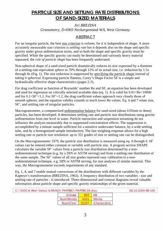
C:\DOCs\Ww\Doku\GRANO\PARTEC\PARTEC01.doc 20.10.2009 09:10h Grösse 865 kB
NumWords 6101 Worte NumChar 32207 Characters
ROTATIONAL ELLIPSOID VERSUS SPHERE AS SHAPE REFERENCE IN PARTICLE SIZE ANALYSIS BY SEDIMENTATION
Most sand-sized particles are irregularly and variously shaped. Ignorance of the nonsphericity by using a sphere as a standard shape introduces a significant error. Its kind depends on the sizing method.
Using sedimentation for size determination, the sphere as standard shape causes apparent reduction of particle size. The size reduction is involved in the current hydrodynamic particle size definitions such as the hydraulic value of SCHÖNE (1868), equivalent radius of ODÉN (1915), sedimentation radius of WA-DELL (1934) and LANE (1947), and (standard) fall diameter of COLBY and CHRISSTENSEN (1957).
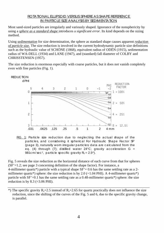
The size reduction is enormous especially with coarse particles, but it does not vanish completely even with fine particles (Fig. 1).
REDUCTION dPHI
.031 .0625 .125 .25 .5 1 2 4 mm
FIG. 1: Particle size reduction due to neglecting the actual shape of the particles, and considering it spherical For Hydraulic Shape Factor SF’ (page 3), naturally worn irregular particles: data are calculated from the eq. (4) through (7); distilled water 24°C; gravity acceleration G = 981cm/sec2, particle specific gravity Rs = 2.5*).
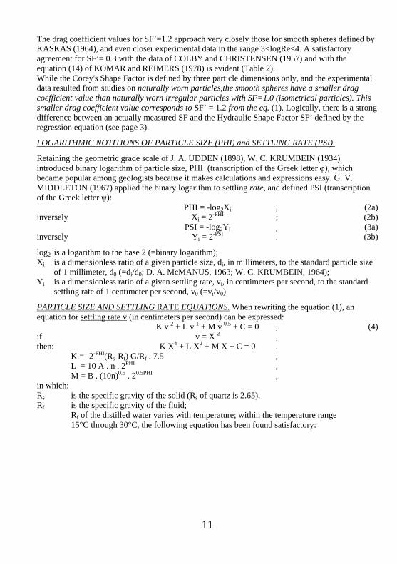
Fig. 5 reveals the size reduction as the horizontal distance of each curve from that for spheres (SF’=1.2; see page 3 concerning definition of the shape factor). For instance, a 4-millimeter quartz*) particle with a typical shape SF’= 0.6 has the same settling rate as a 2-millimeter quartz*) sphere: the size reduction is by 2.0 (=1.04 PHI). A 4-millimeter quartz*) particle with SF’=0.1 has the same settling rate as a 0.48-millimeter quartz*) sphere: the size reduction is by 8.3 (=3.06 PHI). *) The specific gravity Rs=2.5 instead of Rs=2.65 for quartz practically does not influence the size
reduction, since the shifting of the curves of the Fig. 5 and 6, due to the specific gravity change, is parallel.
4
5
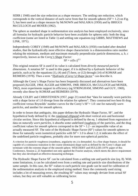
SERR ( 1948) used the size reduction as a shape measure. The settling rate reduction, which corresponds to the vertical distance of each curve from that for smooth spheres (SF’= 1.2) on Fig. 5, has been used as a shape measure by McNOWN and MALAIKA (1950) and by BRIGGS McCULLOCH and MOSER (1962).
The sphere as standard shape in sedimentation size analysis has been employed exclusively, since all formulas for hydraulic particle behavior have been available for spheres only: both the drag coefficient (some are listed in Table 1) and settling rate equations (eg GIBBS, MATTHEWS and LINK, 1971).
Independently COREY (1949) and McNOWN and MALAIKA (1950) concluded after detailed studies, that the hydraulically most effective shape characteristic is a dimensionless ratio number relating the minimum, medium and maximum mutually perpendicular particle dimensions, a, b, c respectively, known as the Corey’s Shape Factor:
SF = a/(b.c)0.5
This original notation SF is used if its value is calculated from directly measured particle dimensions. A notation SF’ is used in this paper, if it is defined by a hydraulic behavior of the particle, such as by the equations (1), (4) and (7) here, or (12) through (14) of KOMAR and REIMERS (1978). Then a term “Hydraulic (Corey’s) Shape factor” can describe it.
Although the Corey’s Shape Factor has been frequently discussed and alternatives have been proposed (ALGER, 1964; ALGER and SIMONS, 1968; BRIGGS, McCULLOCH and MOSER, 1962), most experiments support its efficiency (eg STRINGHAM, SIMONS and GUY, 1969), recently also those by KOMAR and REIMERS (1978).
Already COLBY and CHRISTENSEN (1957, page 21) noted that “data for naturally worn particles with a shape factor of 1.0 diverge from the relation for spheres”. They constructed two best-fit drag coefficient versus Reynolds’ number curves for the Corey’s SF’= 1.0: one for naturally worn particles, and another for smooth spheres.
In order to lessen that ambiguity, this paper defines the Hydraulic Shape Factor, SF’, and the hypothetical body defined by it: the rotational ellipsoid with short vertical axis and horizontal circular section. Since this hypothetical ellipsoid is defined by the eq. 1 obtained from regression of data on naturally worn particles, it absorbs some undefined roughness of the particles, and the drag coefficient values for smooth spheres correspond to the SF’= 1.2 - an impossible value of an actually measured SF. The ratio of the Hydraulic Shape Factor (SF’) values for smooth spheres to those for naturally worn isometrical particles with SF’= 1.0 is about 1.2; it indicates the effect of the undefined particle roughness, probably also for more non-spherical particles.
A criterion for particle roughness (roundness, angularity etc.) is demanded. As a fine shape feature, it should be capable of a continuous transition to the coarse (dominant) shape such as defined by the Corey’s shape and terminate with the extreme shape of the smooth sphere. WEICHERT and HULLER (1979: paper of this Conference, Session 2, 25 September) not only applied the Fourier analysis, which meets the above requirement but they also developed an effective measuring technique.
The Hydraulic Shape Factor SF’ can be calculated from a settling rate and particle size (eq. 8). With some limitations, it can be calculated even from a settling rate and particle size distributions of the same sample. In this case, the SF’-values to each particle size grade can be used for calibration of the sedimentation analysis to the employed sizing method. Since the commonly used sizing includes a lot of measuring errors, the resulting SF’ values may strongly deviate from actual SF values, but they are still valuable as calibrating factor.
6
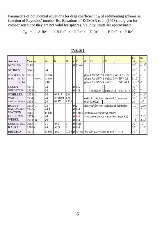
Parameters of polynomial equations for drag coefficient CD of sedimenting spheres as function of Reynolds’ number Re. Equations of KOMAR et al. (1978) are given for comparison since they are not valid for spheres. Validity limits are approximate.
CD = A.Rea + B.Reb + C.Rec + D.Red + E.Ree + F.Ref
TABLE 1
Authors Year a A b B c C d D e E f F Re min.
Re max.
NEWTON 1687 0 (0.44) 103 2.105
STOKES 1845 -1 24 10-7 10-1
KOMAR Eq. 12 et al., Eq. 13 Eq. 14
1978 -1 -0.9721 -1
22.704 23.928 2.16
given for SF’=1 valid: 0.4<SF’<0.8given for SF’=1 valid: 0.4<SF’<0.8 given for SF’=1 valid: SF’=0.4
10-7
5.10-2
5.10-2
2 1 2
OSEEN GOLDSTEIN
1910 1929
-1 -1
24 24
00
4.5 4.5 1 -0.35625 2 0.0832 3 -0.0210512
10-7
10-7 1 2
valid for Stokes’ Reynolds' number SCHILLER WADEL LANGMUIR et al.
1933 1934 1959
-1 -1 -1
24 24 24
-0.313-0.30103-0.37
3.6 1.924.728
0.38 0.0624
10-7
10-7
10-7
8.102
3.103
102
RUBEY DALLAVALLE WATSON GIBBS et al. WEBER
1933 1943 1969 1971 1974
-1 -1 -1 -1 -0.8
24 24.4 14.928 24 26
00000
2 0.4 1.0610.4 0.4
derived for non-spherical particles includes streaming errors ←(convergence value for large Re)
10-7
10-7
-
10-7
1
2.10 2.105
- 2.105
2.105
KÜRTEN et al. KASKAS
1966 1964
-1 -1
21 24
-0.5 -0.5
6 4
00
0.28 0.4
10-7
10-7 104
2.105
BREZINA 1979 -1 23.963 -0.5 4.058 0 0.37965 for SF’1.2; valid: 0.1<SF’<1.2 10-7 104
7
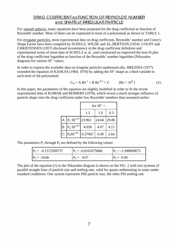
DRAG COEFFICIENT as FUNCTION OF REYNOLDS’ NUMBER and SHAPE of IRREGULAR PARTICLE
For smooth spheres, many equations have been proposed for the drag coefficient as function of Reynolds' number. Most of them can be expressed in form of a polynomial as shown in TABLE 1.
For irregular particles, most experimental data on drag coefficient, Reynolds’ number and Corey's Shape Factor have been compiled by SCHULZ, WILDE and AL-BERTSON (1954). COLBY and CHRISTENSEN (1957) disclosed inconsistency in the drag coefficient definition and experimental terms of some data of SCHULZ et al., and constructed an improved the best fit plot of the drag coefficient logarithm as function of the Reynolds’ number logarithm (Nikuradze diagram) for various SF’ values.
In order to express the available data on irregular particles mathematically, BREZINA (1977) extended the equation of KASKAS (1964, 1970) by adding the SF’ shape as a third variable to each term of the polynomial:
CD = A Re-1 + B Re-0.5 + C [Re < 104 ] (1) .
In this paper, the parameters of the equation are slightly modified in order to fit the recent experimental data of KOMAR and REIMERS (1978), which reveal a much stronger influence of particle shape onto the drag coefficient under low Reynolds' numbers than assumed earlier:
for SF’ =
1.2 1.0 0.3
A P2 SF’P1 23.963 24.66 29.80
B P4 SF’P3 4.058 4.07 4.15
C P6SF’P5 0.37967 0.49 2.64
The parameters P1 through P6 are defined by the following values:
P1 = -0.1572509737 P3 = -0.0161675868 P5 = -1.398809673
P2 = 24.66 P4 = 4.07 P6 = 0.49
The plot of the equation (1) in the Nikuradze diagram is shown on the FIG. 2 with two systems of parallel straight lines of particle size and settling rate, valid for quartz sedimenting in water under standard conditions. One system represents PHI particle size, the other PSI settling rate
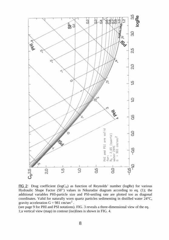
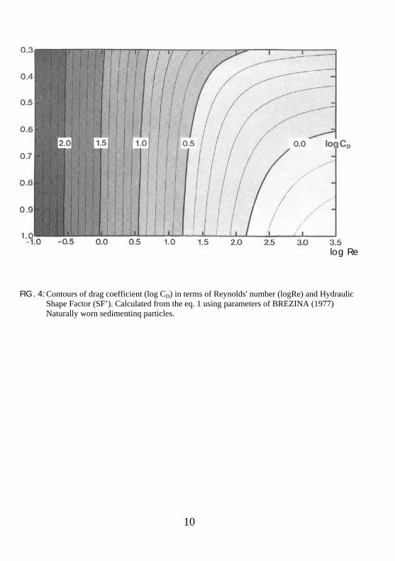
FIG 2: Drag coefficient (logCD) as function of Reynolds’ number (logRe) for various Hydraulic Shape Factor (SF’) values in Nikuradze diagram according to eq. (1); the additional variables PHI-particle size and PSI-settling rate are plotted too as diagonal coordinates. Valid for naturally worn quartz particles sedimenting in distilled water 24°C, gravity acceleration G = 981 cm/sec2 . (see page 9 for PHI and PSI notations). FIG. 3 reveals a three-dimensional view of the eq. 1;a vertical view (map) in contour (iso)lines is shown in FIG. 4.
8
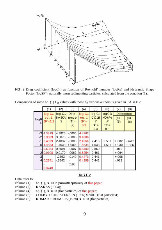
FIG. 3: Drag coefficient (logCD) as function of Reynold’ number (logRe) and Hydraulic Shape
Factor (logSF’); naturally worn sedimenting particles; calculated from the equation (1).
Comparison of some eq. (1) CD values with those by various authors is given in TABLE 2.
(1) (2) (3) (4) (5) (6) (7) (8) Difference
logRe
log CD eq. 1,
SF’=1.2
log CD KASKA
S
Diffe-rence (1) - (2)
log CD eq. 1 SF’= 0.3
log CD COLB
Y SF’= 0.3
logCD KOMA
R SF’= 0.3
(4) - (5)
(4) - (6)
-3 -2
4.3819 3.3869
4.3825 3.3875
-,0006 -.0006
4.4762 3.4806
-1 0
2.4029 1.4533
2.4032 1.4533
-.0003 +.0000
2.4966 1.5634
2.415 1.533
2.537 1.537
+.082 +.030
-.040 +.026
1 2
0.6084 0.0108
0.6091 0.0170
-.0007 -.0062
0.8409 0.5254
0.860 0.461
-.019 +.064
3 4
- 0.2741 - 0.3740
-.2592 -.3542
-.0149 -.0198
0.4473 0.4289
0.441 0.441
+.006 -.012
TABLE 2 Data refer to: column (1): eq. (1), SF’=1.2 (smooth spheres) of this paper; column (2): KASKAS (1964); column (4): eq. (1), SF’=0.3 (flat particles) of this paper; column (5): COLBY + CHRISTENSEN (1956) SF’=0.3 (flat particles); column (6): KOMAR + REIMERS (1978) SF’=0.3 (flat particles).
9
log Re
FIG. 4: Contours of drag coefficient (log CD) in terms of Reynolds' number (logRe) and Hydraulic
Shape Factor (SF’). Calculated from the eq. 1 using parameters of BREZINA (1977) Naturally worn sedimentinq particles.
10
11
The drag coefficient values for SF’=1.2 approach very closely those for smooth spheres defined by KASKAS (1964), and even closer experimental data in the range 3<logRe<4. A satisfactory agreement for SF’= 0.3 with the data of COLBY and CHRISTENSEN (1957) and with the equation (14) of KOMAR and REIMERS (1978) is evident (Table 2). While the Corey's Shape Factor is defined by three particle dimensions only, and the experimental data resulted from studies on naturally worn particles,the smooth spheres have a smaller drag coefficient value than naturally worn irregular particles with SF=1.0 (isometrical particles). This smaller drag coefficient value corresponds to SF’ = 1.2 from the eq. (1). Logically, there is a strong difference between an actually measured SF and the Hydraulic Shape Factor SF’ defined by the regression equation (see page 3).
LOGARITHMIC NOTITIONS OF PARTICLE SIZE (PHI) and SETTLING RATE (PSI).
Retaining the geometric grade scale of J. A. UDDEN (1898), W. C. KRUMBEIN (1934) introduced binary logarithm of particle size, PHI (transcription of the Greek letter φ), which became popular among geologists because it makes calculations and expressions easy. G. V. MIDDLETON (1967) applied the binary logarithm to settling rate, and defined PSI (transcription of the Greek letter ψ): PHI = -log2Xi , (2a) inversely Xi = 2-PHI ; (2b) PSI = -log2Yi , (3a) inversely Yi = 2-PSI . (3b)
log2 is a logarithm to the base 2 (=binary logarithm); Xi is a dimensionless ratio of a given particle size, di, in millimeters, to the standard particle size
of 1 millimeter, d0 (=di/d0; D. A. McMANUS, 1963; W. C. KRUMBEIN, 1964); Yi is a dimensionless ratio of a given settling rate, vi, in centimeters per second, to the standard
settling rate of 1 centimeter per second, v0 (=vi/v0).
PARTICLE SIZE AND SETTLING RATE EQUATIONS. When rewriting the equation (1), an equation for settling rate v (in centimeters per second) can be expressed: K v-2 + L v-1 + M v-0.5 + C = 0 , (4) if v = X-2 , then: K X4 + L X2 + M X + C = 0 . K = -2-PHI(Rs-Rf) G/Rf . 7.5 , L = 10 A . n . 2PHI , M = B . (10n)0.5 . 20.5PHI , in which: Rs is the specific gravity of the solid (Rs of quartz is 2.65), Rf is the specific gravity of the fluid;
Rf of the distilled water varies with temperature; within the temperature range 15°C through 30°C, the following equation has been found satisfactory:
particle size
FIG. 5: Influence of particle shape (SF’) onto the PSI-settling rate plotted as function of the PHI-nominal diameter; naturally worn irregular particles sedimenting in distilled water 24°C, under gravity acceleration G = 981 cm/sec2; calculated from the eq. (4); four diagrams for four specific gravity values of particles: a) Rs = 2.5 b) Rs = 5 c) Rs = 10 d) Rs = 20
12
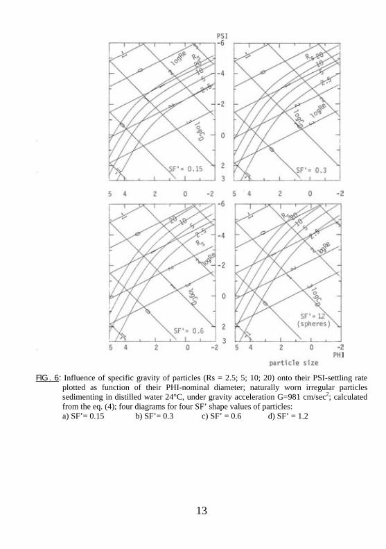
FIG. 6: Influence of specific gravity of particles (Rs = 2.5; 5; 10; 20) onto their PSI-settling rate
plotted as function of their PHI-nominal diameter; naturally worn irregular particles sedimenting in distilled water 24°C, under gravity acceleration G=981 cm/sec2; calculated from the eq. (4); four diagrams for four SF’ shape values of particles: a) SF’= 0.15 b) SF’= 0.3 c) SF’ = 0.6 d) SF’ = 1.2
13
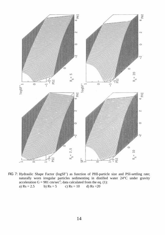
FIG 7: Hydraulic Shape Factor (logSF’) as function of PHI-particle size and PSI-settling rate; naturally worn irregular particles sedimentinq in distilled water 24°C under gravity acceleration G = 981 cm/sec2; data calculated from the eq. (1): a) Rs = 2.5 b) Rs = 5 c) Rs = 10 d) Rs =20
14
15
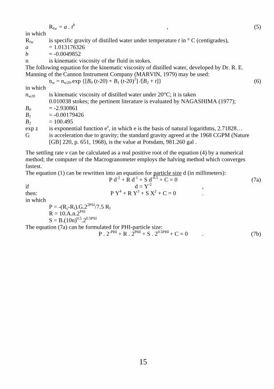
Rfw = a . tb , (5) in which Rfw is specific gravity of distilled water under temperature t in ° C (centigrades), a = 1.013176326 b = -0.0049852 n is kinematic viscosity of the fluid in stokes. The following equation for the kinematic viscosity of distilled water, developed by Dr. R. E. Manning of the Cannon Instrument Company (MARVIN, 1979) may be used: nw = nw20.exp {[B0 (t-20) + B1 (t-20)2] /[B2 + t]} (6) in which nw20 is kinematic viscosity of distilled water under 20°C; it is taken
0.010038 stokes; the pertinent literature is evaluated by NAGASHIMA (1977); B0 = -2.930861 B1 = -0.00179426 B2 = 100.495 exp z is exponential function ez, in which e is the basis of natural logarithms, 2.71828… G is acceleration due to gravity; the standard gravity agreed at the 1968 CGPM (Nature
[GB] 220, p. 651, 1968), is the value at Potsdam, 981.260 gal .
The settling rate v can be calculated as a real positive root of the equation (4) by a numerical method; the computer of the Macrogranometer employs the halving method which converges fastest. The equation (1) can be rewritten into an equation for particle size d (in millimeters): P d-2 + R d-1 + S d-0.5 + C = 0 (7a) if d = Y-2 , then: P Y4 + R Y3 + S X2 + C = 0 . in which P = -(Rs-Rf).G.22PSI/7.5 Rf R = 10.A.n.2PSI
S = B.(10n)0.5.20.5PSI The equation (7a) can be formulated for PHI-particle size: P . 2-PHI + R . 2PHI + S . 20.5PHI + C = 0 . (7b)
16
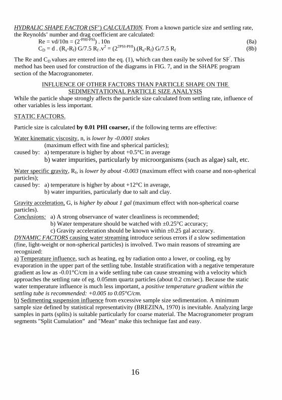
HYDRALIC SHAPE FACTOR (SF’) CALCULATI0N. From a known particle size and settling rate, the Reynolds’ number and drag coefficient are calculated: Re = vd/10n = (2-PHI-PSI) . 10n (8a) CD = d . (Rs-Rf) G/7.5 Rf .v2 = (22PSI-PHI).(Rs-Rf) G/7.5 Rf (8b)
The Re and CD values are entered into the eq. (1), which can then easily be solved for SF’. This method has been used for construction of the diagrams in FIG. 7, and in the SHAPE program section of the Macrogranometer.
INFLUENCE OF OTHER FACTORS THAN PARTICLE SHAPE ON THE SEDIMENTATIONAL PARTICLE SIZE ANALYSIS
While the particle shape strongly affects the particle size calculated from settling rate, influence of other variables is less important.
STATIC FACTORS.
Particle size is calculated by 0.01 PHI coarser, if the following terms are effective:
Water kinematic viscosity, n, is lower by -0.0001 stokes (maximum effect with fine and spherical particles); caused by: a) temperature is higher by about +0.5°C in average b) water impurities, particularly by microorganisms (such as algae) salt, etc.
Water specific gravity, Rf, is lower by about -0.003 (maximum effect with coarse and non-spherical particles); caused by: a) temperature is higher by about +12°C in average, b) water impurities, particularly due to salt and clay.
Gravity acceleration, G, is higher by about 1 gal (maximum effect with non-spherical coarse particles). Conclusions: a) A strong observance of water cleanliness is recommended; b) Water temperature should be watched with ±0.25°C accuracy; c) Gravity acceleration should be known within ±0.25 gal accuracy. DYNAMIC FACTORS causing water streaming introduce serious errors if a slow sedimentation (fine, light-weight or non-spherical particles) is involved. Two main reasons of streaming are recognized: a) Temperature influence, such as heating, eg by radiation onto a lower, or cooling, eg by evaporation in the upper part of the settling tube. Instable stratification with a negative temperature gradient as low as -0.01°C/cm in a wide settling tube can cause streaming with a velocity which approaches the settling rate of eg. 0.05mm quartz particles (about 0.2 cm/sec). Because the static water temperature influence is much less important, a positive temperature gradient within the settling tube is recommended: +0.005 to 0.05°C/cm. b) Sedimenting suspension influence from excessive sample size sedimentation. A minimum sample size defined by statistical representativity (BREZINA, 1970) is inevitable. Analyzing large samples in parts (splits) is suitable particularly for coarse material. The Macrogranometer program segments "Split Cumulation” and "Mean" make this technique fast and easy.
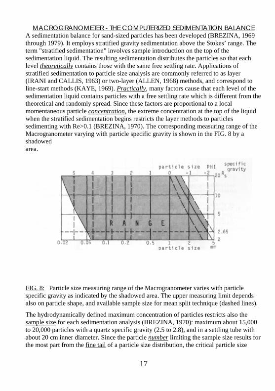
MACROGRANOMETER - THE COMPUTERIZED SEDIMENTATION BALANCE A sedimentation balance for sand-sized particles has been developed (BREZINA, 1969 through 1979). It employs stratified gravity sedimentation above the Stokes’ range. The term "stratified sedimentation" involves sample introduction on the top of the sedimentation liquid. The resulting sedimentation distributes the particles so that each level theoretically contains those with the same free settling rate. Applications of stratified sedimentation to particle size analysis are commonly referred to as layer (IRANI and CALLIS, 1963) or two-layer (ALLEN, 1968) methods, and correspond to line-start methods (KAYE, 1969). Practically, many factors cause that each level of the sedimentation liquid contains particles with a free settling rate which is different from the theoretical and randomly spread. Since these factors are proportional to a local momentaneous particle concentration, the extreme concentration at the top of the liquid when the stratified sedimentation begins restricts the layer methods to particles sedimenting with Re>0.1 (BREZINA, 1970). The corresponding measuring range of the Macrogranometer varying with particle specific gravity is shown in the FIG. 8 by a shadowed area.
FIG. 8: Particle size measuring range of the Macrogranometer varies with particle specific gravity as indicated by the shadowed area. The upper measuring limit depends also on particle shape, and available sample size for mean split technique (dashed lines).
The hydrodynamically defined maximum concentration of particles restricts also the sample size for each sedimentation analysis (BREZINA, 1970): maximum about 15,000 to 20,000 particles with a quartz specific gravity (2.5 to 2.8), and in a settling tube with about 20 cm inner diameter. Since the particle number limiting the sample size results for the most part from the fine tail of a particle size distribution, the critical particle size
17
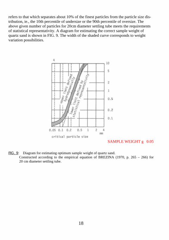
refers to that which separates about 10% of the finest particles from the particle size dis-tribution, ie., the 10th percentile of undersize or the 90th percentile of oversize. The above given number of particles for 20cm diameter settling tube meets the requirements of statistical representativity. A diagram for estimating the correct sample weight of quartz sand is shown in FIG. 9. The width of the shaded curve corresponds to weight variation possibilities.
SAMPLE WEIGHT g 0.05
FIG. 9: Diagram for estimating optimum sample weight of quartz sand. Constructed according to the empirical equation of BREZINA (1970, p. 265 – 266) for 20 cm diameter settling tube.
18
"TERMINAL-
\ T
EL
ETYPE
REC(
RD
\
- CONTROL & PROCESSING SYSTEM - CONTROL MODULE V - ""^ - y \zz_______
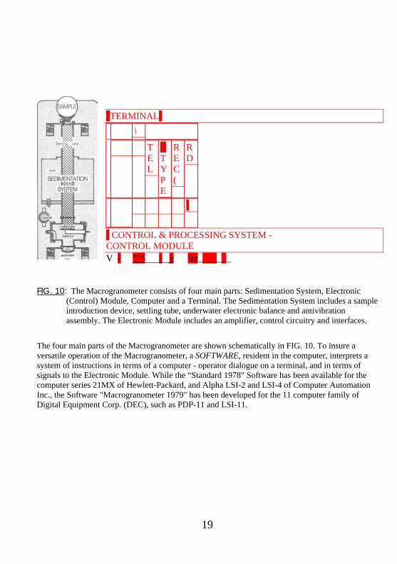
FIG. 10: The Macrogranometer consists of four main parts: Sedimentation System, Electronic (Control) Module, Computer and a Terminal. The Sedimentation System includes a sample introduction device, settling tube, underwater electronic balance and antivibration assembly. The Electronic Module includes an amplifier, control circuitry and interfaces.
The four main parts of the Macrogranometer are shown schematically in FIG. 10. To insure a versatile operation of the Macrogranometer, a SOFTWARE, resident in the computer, interprets a system of instructions in terms of a computer - operator dialogue on a terminal, and in terms of signals to the Electronic Module. While the “Standard 1978" Software has been available for the computer series 21MX of Hewlett-Packard, and Alpha LSI-2 and LSI-4 of Computer Automation Inc., the Software "Macrogranometer 1979" has been developed for the 11 computer family of Digital Equipment Corp. (DEC), such as PDP-11 and LSI-11.
19
20
The Software 1979 consists of two parts callable from the operation system: 1) “SEDIM”, covering a modified Standard 1978 performance, and 2) "SHAPE", performing a Gauss-multicomponental regression (I. CLARK, 1977), and
calculation of the Hydraulic Shape Factor SF’ values to each 0.02 PHI particle size step from a PHI-non-sedimentational, eg. sieving analysis, and from a PSI-sedimentation analysis, matched by PSI-inverse distribution function of the PHI-distribution function.
The Software 1979 requires 32kw (=64kByte) memory space. While the Macrogranometer hardware is fully described in BREZINA (1977), its Software 1978 and 1979 facilities are characterized in BREZINA (1978) and (1979) respectively.
CONCLUSIONS The hydrodynamically specified shape of irregular non-spherical sand-sized particles (equation 1) allows for a closer approach to the nominal diameter (=volume-equivalent sphere diameter) by sedimentation analysis. Sedimentation analysis of sand-sized material contributes significantly to its characteristics. A direct sedimentational measuring of particulate distributions with different variables, such as PHI-particle size specified by shape, PSI-settling rate, logRe with specified particle shape, enable new insights into disperse systems in different fields.
TABLES
The following tables are enclosed to this paper:
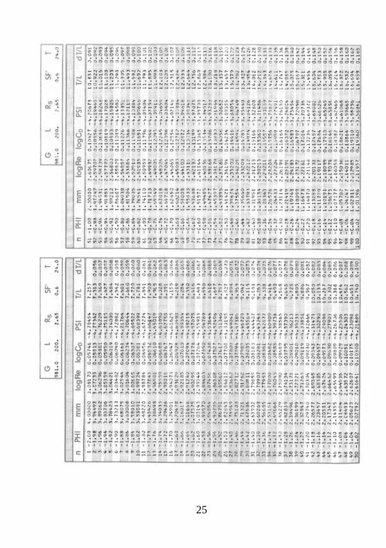
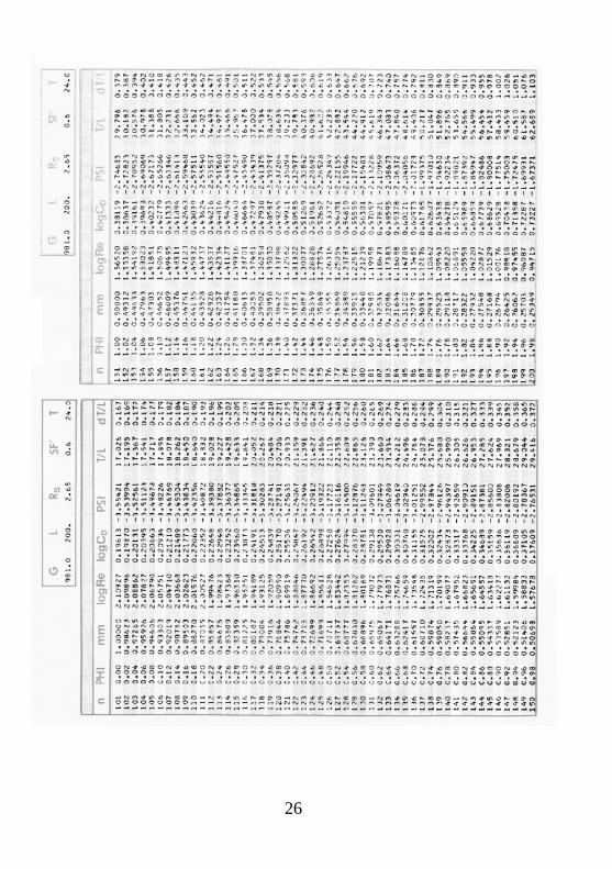
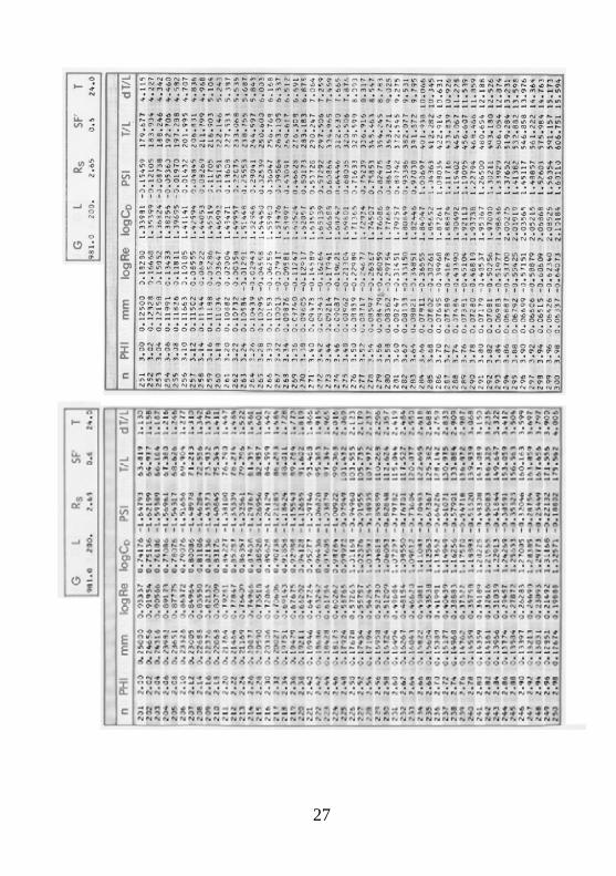
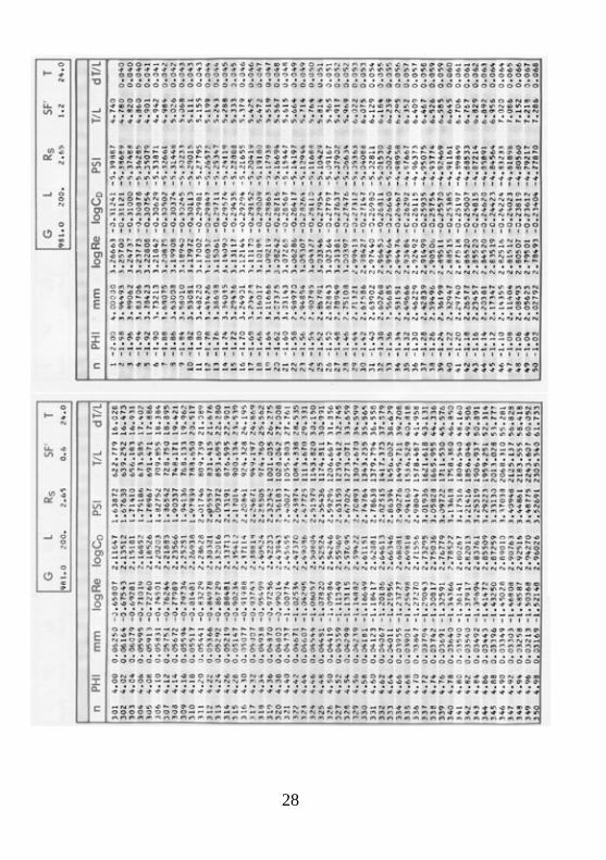
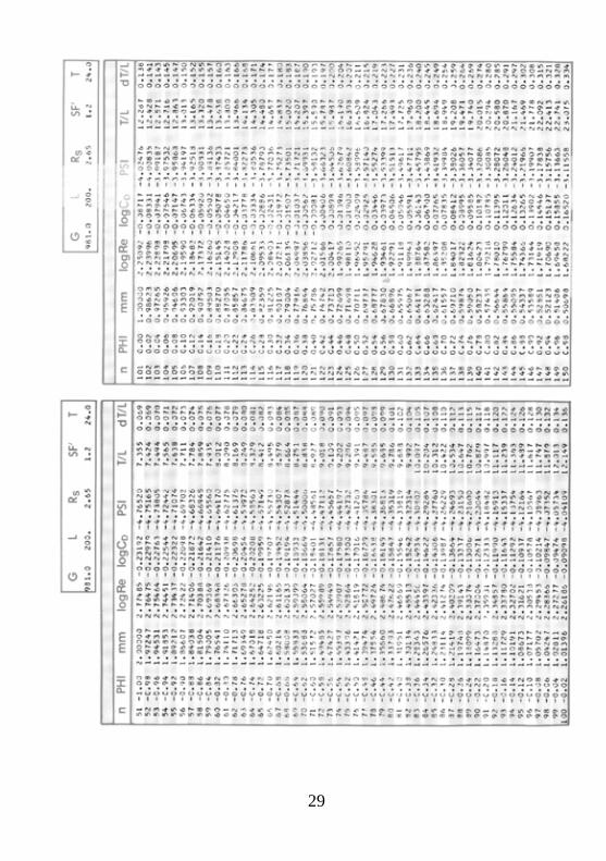
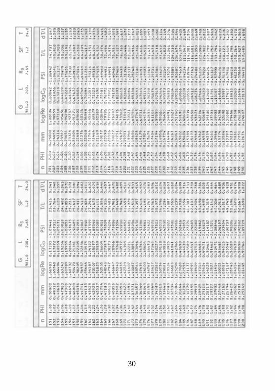
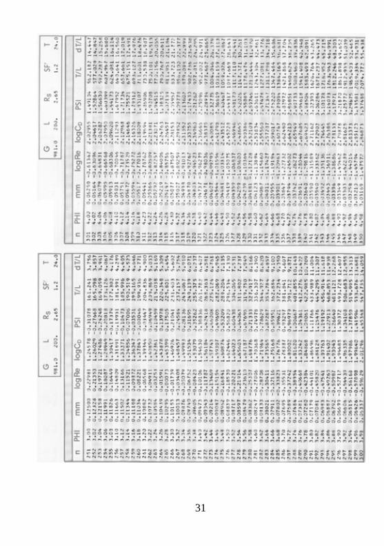
1) Reynolds' number, drag coefficient, PSI-settling rate, settling time and settling time difference, as functions of PHI-particle size with hydraulically defined shape:
[logRe, logCD, PSI, T/L, dT/L] = F(PHI, SF), gravity acceleration G = 981, sedimentation length 200cm, particle specific gravity Rs =2,65, distilled water temperature T=24°C;
a) for Hydraulic Shape Factor SF’=0.6 (7 pages = page 22 - 28) b) for Hydraulic Shape Factor SF’=1.2 (7 pages = page 29 - 35)
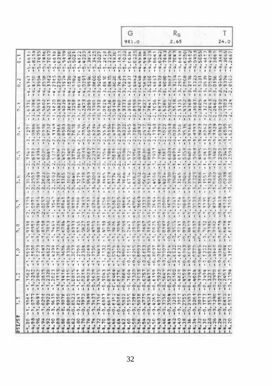
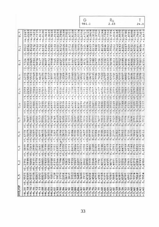
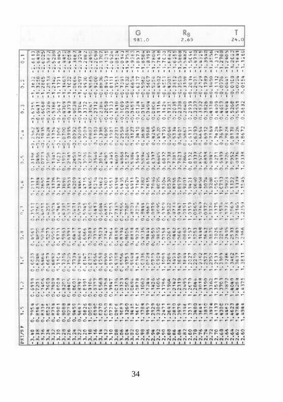
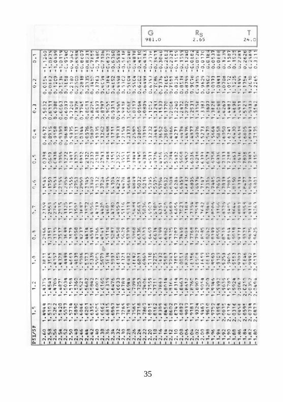
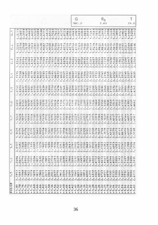
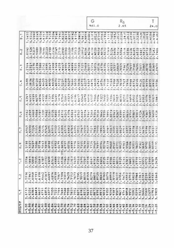
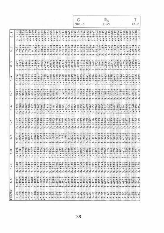
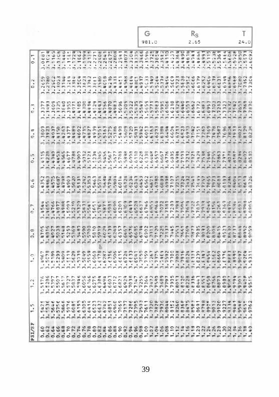
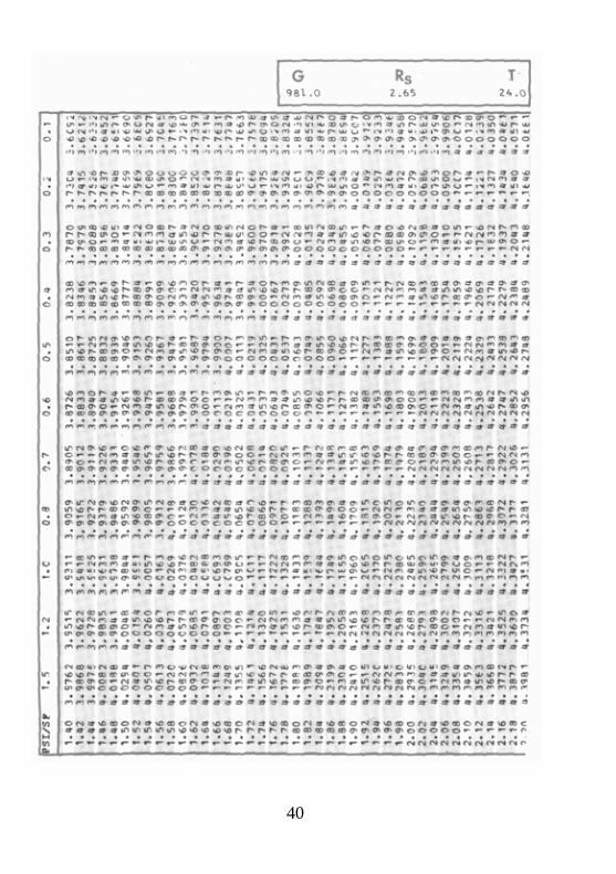
2) PHI-particle size as function of PSI-settling rate and SF’ Hydraulic Shape: PHI = F(PSI, SF’); gravity acceleration G = 981, particle specific gravity Rs = 2.65 distilled water temperature T=24°C (9 pages = page 36 - 44)
All values of the Tables have been calculated using the equations of this paper.
21
REFERENCES ALGER, G.R., 1964, Ph.D.Dissertation, Dept. of Civil Engineering, Colorado State University, 110
pages: Terminal Fall Velocity of Particles of Irregular Shapes as Affected by Surface Area. ALGER, G.R. + D.B. SIMONS, 1968, Jour. Hydraulics Division, Proceedings ASCE, HY 3/May,
p. 721 - 737: Fall Velocity of Irregular Shaped Particles, ALLEN, T., 1968, Chapman & Hall Ltd, London, 248 pages: Particle Size Measurement. BREZINA, J., 1963, Jour. Sedimentary Petrology, 33, No. 4/Dec, p. 931 - 937: Kapteyn's
Tranformation of Grain Size Distribution. - - 1969, ibidem, 39, No. 4/Dec, p. 1627 - 1631: Granulometer - a Sediment Analyzer Directly
Writing Grain Size Distribution Curves. - - 1970, in: M.J. GROVES & J.L. WYATT-SARGENT (editors), Particle Size Analysis 1970
Conference, Univ. of Bradford, England; The Society of Analytical Chemistry, London 1972, p. 255 - 266: Stratified Sedimentation above Stokes’ Range and its Use for Particle Size Analysis.
- - 1971, Bericht über Forschungsarbeiten des Authors am Institut für Mechanische Verfahrenstechnik der Universität Karlsruhe (1968 - 1970) für die Deutsche Forschungsgemeinschaft (not published) 48 pages: Untersuchungen am einem Gerät zur Sedimentationsanalyse im Teilchengrößenbereich oberhalb 60 µm.
- - 1977, Granometry, D-6903 Neckargemünd (not published), 30 pages: Macrogranometer Standard 1977 (Allgemeine Beschreibung + Spezifikation).
- - 1978, Granometry, D-6903 Neckargemünd (not published), 22 pages: Macrogranometer Standard 1978 (Operation Program Manual, Third Edition,
10 November 1978. - - 1979, Granometry, D-6903 Neckargemünd (not published), 18 pages: Macrogranometer
1979, Parts (quotations of Computer components, Mass Memory and Terminal alternatives are given as well).
BRIGGS, L.I., D.S. McCULLOCH + Frank MOSER, 1962, Jour.Sedimentary Petrology, 32, 4/Dec., p. 645 - 656: The Hydraulic Shape of Sand Particles.
CLARK, Isobel, 1977, Computer & Geosciences (Pergamon Press), 3, p. 245 – 256: R0KE, a Computer Program for Non-Linear Least-Squares Decomposition of Mixtures of Distributions.
COLBY, B.C. + R.P. CHRISTENSEN, 1957, St. Anthony Falls Hydraulic Laboratory, Minneapolis, Minnesota, USA, Report Nr. 12/Dec, 55 pages: Some Fundamentals of Particle Size Analysis.
COREY, A.T., 1949, M.S. Thesis, Colorado Agricultural and Mechanical College, Fort Collins, Colorado, USA, December, 102 pages: Influence of Shape on the Fall Velocity of Sand Grains.
DALLAVALLE, J.M., 1943, Pitman Publ. Co., New York-London, 1st Ed. (2nd Ed. 1948): Micromeritics.
GIBBS, R.J., M.P. MATTHEWS + D.A. LINK, 1971, Jour. Sedimentary Petrology, 41, 1/March, p. 7 - 18: The Relationship between Sphere Size and Settling Velocity.
GOLDSTEIN, Sydney, 1929, Proc. Royal Soc. London, A/Math. and Phys. Sci., 123, No. 791/6th March, p. 225 - 235: The Steady Flow of Viscous fluid past a fixed Spherical Obstacle at Small Reynolds’ Numbers.
22
IRANI, R.R. + C.F. CALLIS, 1963, J. Willey & Sons, New York, 165+VIII pages: Particle Size: Measurement, Interpretation and Application.
KASKAS, A.A., 1964, Diplomarbeit am Lehrstuhl für Thermodynamik und Verfahrenstechnik der T.U. Berlin: Berechnungen der stationären und instationären Bewegung von Kugeln in ruhenden und strömenden Medien.
- - 1970, Doktor-Ingenieur-Dissertation, Inst. f. Verfahrenstechnik, Fakultät für Maschinenwesen der TU Berlin, 164 pages: Schwarmgeschwindigkeit in Mehrkornsuspensionen am Beispiel der Sedimentation.
KAYE, B.H., M.R. JACKSON + R. KAHRUN, 1969, Powder Technology, 2, No. 5, p. 290 - 300: The Stability of Line Start Suspension Systems in the Centrifugal Disc Photosedimentometer.
KOMAR, P.D. + C.E. REIMERS, 1978, Jour. Geology, 86, Nr. 2/March, p. 193 - 209: Grain Shape Effects on Settling Rates.
KRUMBEIN, W.C., 1934, Jour. Sedimentary Petrology, 4, No. 2/Aug., p. 65 - 77: Size Frequency Distribution of Sediments.
1964, ibidem, 34, No. 1/March, p. 195 - 197: Some Remarks on the phi-Notation. KÜRTEN, H., J. RAASCH + H. RUMPF, 1966, Chem.-Ing.-Technik, 38, No. 9, p. 941 - 948:
Beschleunigung eines kugelförmigen Feststoffteilchens im Strömungsfeld konstanter Geschwindigkeit.
LANE, E.W., 1947, Trans. American Geophysical Union, 28, No. 6, page 937: Report of the Subcommittee on Sediment Terminology.
LANGMUIR et al., 1959, quoted in L.B. T0R0BIN + W.H. GAUVIN (1959 through 1961): Fundamental Aspects of Solids-Gas Flow (Can. J. Chem. Engng., 37/1959, 4, p. 129 - 141, 5, p. 167 - 176, 6, p. 224 – 236; 38/1960, 5, p. 142 - 153, 6, p. 189 - 200; 33/1961, 3, p. 113 - 121.
MARVIN, R.S., 1979, US Dept. of Commerce, National Bureau of Standards, Wash., D.C., personal communication about development of Dr. R.E. MANNING of the Cannon Instrument Company.
McMANUS, D-A., 1963, Jour. Sedimentary Petrology, 33, No. 3/Sept., p. 670-674: A Criticism of Certain Usage of the phi Notation.
McNOWN, J.S. + J. MALAIKA, 1950, American Geophysical Union Transactions, 31, No. 1/Febr, p. 74 - 82: Effects of Particle Shape on Settling Velocity at Low Reynold’ Numbers.
MIDDLET0N, G.V., 1967, Canadian Journal of Earth Sciences, 4, p. 475 – 505 (PSI-definition: p. 483 - 485): Experiments on Density and Turbidity Currents, III: Deposition.
NAGASHIMA, A., 1977, Journal Physical and Chemical Reference Data (ASC, AIP and NBS Publication), 6, No. 4 (Reprint No. 105), p. 1133 - 1166: Viscosity of Water Substance - New International Formulation and its background.
NEWTON, Sir Isaac, 1687, Edition tertia aucta & emendata (Reprinted by W. Thompson & H. Blackburn, 1871), pagina 46, Philosophia Naturalis Principia Mathematica, Liber II, Sectio II, "De motu corporum quibus resistur in duplicata ratione velocitatum”, Propositio V, Theorema III (English translation by Andrew Motte, 1819, page 89).
ODÉN, Sven, 1915, Int. Mitt. f. Bodenkunde, 5, p. 257 - 311: Eine neue Methode mechanischen Bodenanalyse.
0SEEN, C.W., 1910, Archiv för Mat. Astron. och Fysik, 6, No. 16, p. 23 - 29: Ueber den Gültigkeitsbereich der Stokes'schen Widerstandsformel.
23
RUBEY, W.W., 1933, Amer. J. Sci 5th Ser., 25, No. 148/April ., p. 325 - 338: Settling Velocities of Gravel, Sand and Silt Particles.
SCHILLER, L., 1933, Handbuch der Experimental Physik, vol. IV/2, Akademische Verlagsgesellschaft, Leipzig, p. 348, 369: Fallversuche mit Kugeln und Scheiben.
SCHÖNE, E., 1868, Zeitschrift f. anal. Chemie, 7, p. 29 - 47: Ueber einen neuen Apparat für die Schlämmanalyse.
SCHULZ, E. R., WILDE + M.L. ALBERTSON, 1954, Colo. Agric. & Mechanical College, Fort Collins, Colo., MRD Sediment Series, No. 5/July (CER 54EFS6), 161 pages: Influence of Shape on the Fall Velocity of Sedimentary Particles.
SERR III, E F., 1948, Master's Thesis in Irrigation Engineering, Colorado A & M College, Fort Collins, Colorado: A Comparison of the Sedimentation Diameter and the Sieve Diameter for Various Types of Natural Sands.
STOKES, G.G., 1845, Trans. Cambr. Philos. Soc., 3, p. 287: On the Theories of the Internal Friction of Fluids in Motion of Elastic Solids.
STRINGHAM, G.E., D.B.. SIMONS + H.F. GUY, 1969, Geol. Survey Prof. Paper 562-C, p. CI - C36: The Behavior of Large Particles Falling in Quiescent Liquids.
UDDEN, J.A., 1898, Augustana Library Publication, I, p. 36: The Mechanical Composition of Wind Deposits.
WADELL, Hakon, 1934a, Jour. Franklin Inst., 217, No. 4 April, p. 459 - 490: The Coefficient of Resistance as a Function of Reynolds’ number for Solids of Various Shapes.
1934b, Physics, 5, No. 10/0ct., p. 281 - 291: Some New Sedimentation Formulas. WATSON, R.L., 1969, Water Resources Research (Amer. Geophys. Union, Wash. D.C), 5. No.
5/0ct., p. 1147 - 1150: Modified Rubey's Law accurately Predicts Sediment Settling Velocities. WEBER, M., 1974, Krauskopf-Verlag: Strömung-Fördertechnik. WEICHERT, R. + D. HULLER, 1979, 2nd European Symposium on Particle Characterisation,
Nürnberg, 24 - 26 September, Session 2, Tuesday 25 September, 11:30: Volume Determination and Recognition of Shape of Irregularly Shaped Particles by Means of Three-Dimensional Image Analysis.
NOTATION
A, B, C Parameters of the polynomial equation (1) defined on the page 5; they appear also in the eq. (4) and (7).
A, B, C, D, E, F Parameters of the general polynomial equation of the a, b, c, d, e, f TABLE 1, page 4.
a, b Parameters of the eq. (5), page 13 for specific gravity of distilled water as function of temperature in centigrades.
A, b, c The minimum, medium and maximum mutually perpendicular dimensions of a particle, defining the Corey’s Shape Factor, SF’ page 3.
B0, B1, B2 Parameters of the eq. (6), page 13, for kinematic viscosity of distilled water.
d particle size in millimeters; it refers to the diameter of a sphere with volume equivalent to that of an irregular particle, or of the hydraulically equivalent shape-defined ellipsoid (the hydraulic equivalence is discussed on the page 3.
24
dT/L settling time difference (in seconds) between particles differing in their size by 0.02 PHI (appears in the Tables of the Appendix).
CD drag coefficient defined by the eq. (8b) it corresponds to the German term "Widerstandsbeiwert" indicated by Cw; see page 14.
e basis of natural logarithms, 2.71828...
exp exponential function ez.
G Gravity acceleration in gal (cm/sec2) it appears in eq. (4), page 9, eq. (7), page 13, and eq. (8), page 14.
G gramm
K, L, M Parameters of the polynomial eqation (4), defined on the p. 4.
L Sedimentation length in centimeters; it appears in the Tables of the Appendix.
log2 logarithm to the base 2 (=binary logarithm), page 9.
n kinematic viscosity of a fluid in stokes; page 13.
nw kinematic viscosity of distilled water; page 13.
nw20 kinematic viscosity of distilled water at 20°C; page 13
P, R, S Parameters of the polynomial eq. (7), defined on the page 13.
P1 through P6 Parameters of the polynomial eq. (1), defined on the page 3.
PHI, PSI logarithmic notations of particle size and settling rate respectively, defined on the page 9.
Re Reynolds’ number defined by the eq. (8a), page 14.
Rf Specific gravity of fluid.
Rs Specific gravity of distilled water; eq. (5), page 13. Specific gravity of solid.
SF Corey’s Shape Factor defined on the page 3 (calculated from the geometrically measured values).
SF’ Hydraulic Shape Factor defined on the page 3 (calculated by using a regression equation, eg. eq. (1) of this paper as described on the page 14, from settling rate and particle size values); it appears in eq. (1), (4) and (7).
t Temperature in °C (centigrades).
T Time in seconds - appears in the Tables of the Appendix.
v particle settling rate in centimeters per second.
Xi, Yi Dimensionless ratio of a given particle size, di in millimeters, to the standard particle size of 1 millimeter, d0, Xi = di/d0, and of a given settling rate in centimeters per second, vi, to the standard settling rate of 1 centimeter per second, v0, Yi = vi/v0 respectively, page 9.
25
26
27
28
29
30
31
32
33
34
35
36
37
38
39
40
41
42
C:\DOCs\Ww\Doku\GRANO\PARTEC\PARTEC01.doc 20.10.2009 09:10h Grösse 865 kB NumWords 6101 Worte NumChar 32207 Characters


