Particle Transfer from Magnetic Plugs Mervin H.Jones Swansea Tribology Services Ltd University of Wales Swansea Swansea, UK SA2 8PP Abstract: Magnetic drain plugs have been in use for over thirty years and have developed from simple magnets to self indicating devices. The purpose of this paper is to review the debris transfer from the magnetic plug and suggest procedures to reduce the operator effort, increase the efficiency of the debris transfer and to improve measurement repeatability. Three new procedures are also proposed for review :the fitting of a plastic or metallic sheath, neutralisation of the magnetic attraction and the use of wax to remove the debris. Keywords: Condition monitoring; magnetic drain plugs; wear debris analysis. Introduction: Magnetic plugs have been in use for over thirty years and have developed from simple magnets to self indicating devices e.g. QDM - Quantitative Debris Monitor [1]. In many current applications, both civil and military, a standard magnetic plug which has to be removed from the system for visual inspection is still utilised and the method of particle transfer from the plug has basically remained unchanged :an initial solvent cleaning process followed by an application of sellotape (Figure 1). Optical microscopy and X-Ray Fluorescence have enhanced particle recognition by determining the material composition of the collected debris. The advent of computer imaging analysis, numerical and neural network analysis are currently generating expert systems to automatically classify the wear debris generated during the wear process.L[2]. It is the purpose of this paper to review the transfer procedures of the attached debris from the magnetic plug and suggest modifications to reduce the operator effort, increase the efficiency of the debris extraction and to improve measurement repeatability. Three new techniques are also proposed for review :the fitting of a plastic or metallic sheath, neutralisation of the magnetic attraction and the use of wax to remove the debris. Standard Sellotape Method: This method requires an initial cleaning of the magnetic plug by a suitable solvent. The advent of the 'Montreal Protocol' for solvents and its 19980624 074 DT0 QUAITY INSPECTE IL
Transcript
Particle Transfer from Magnetic Plugs
Mervin H.JonesSwansea Tribology Services Ltd
University of Wales SwanseaSwansea, UK SA2 8PP
Abstract: Magnetic drain plugs have been in use for over thirty years and havedeveloped from simple magnets to self indicating devices. The purpose of this paper is toreview the debris transfer from the magnetic plug and suggest procedures to reduce theoperator effort, increase the efficiency of the debris transfer and to improve measurementrepeatability. Three new procedures are also proposed for review :the fitting of a plasticor metallic sheath, neutralisation of the magnetic attraction and the use of wax to removethe debris.
Keywords: Condition monitoring; magnetic drain plugs; wear debris analysis.
Introduction: Magnetic plugs have been in use for over thirty years and have developedfrom simple magnets to self indicating devices e.g. QDM - Quantitative Debris Monitor[1]. In many current applications, both civil and military, a standard magnetic plug whichhas to be removed from the system for visual inspection is still utilised and the method ofparticle transfer from the plug has basically remained unchanged :an initial solventcleaning process followed by an application of sellotape (Figure 1). Optical microscopyand X-Ray Fluorescence have enhanced particle recognition by determining the materialcomposition of the collected debris. The advent of computer imaging analysis, numericaland neural network analysis are currently generating expert systems to automaticallyclassify the wear debris generated during the wear process.L[2].
It is the purpose of this paper to review the transfer procedures of the attached debris fromthe magnetic plug and suggest modifications to reduce the operator effort, increase theefficiency of the debris extraction and to improve measurement repeatability. Three newtechniques are also proposed for review :the fitting of a plastic or metallic sheath,neutralisation of the magnetic attraction and the use of wax to remove the debris.
Standard Sellotape Method: This method requires an initial cleaning of the magneticplug by a suitable solvent. The advent of the 'Montreal Protocol' for solvents and its
19980624 074DT0 QUAITY INSPECTE IL
implementation have created difficulties due to the absence of an equally efficientalternative to the chlorinated hydrocarbons. Alternatives have
Figure 1 Typical magnetic plugs
however been proposed and accepted by the TSC of JOAP, Pensacola [3]. After removalof all traces of the lubricant or hydraulic fluid from the face of the magnetic plug a strip ofsellotape is pressed against the plug face and peeled away with the wear debris andcontaminants attached to the adhesive face of the sellotape. At this stage the tape isattached to a record card and may then be placed on a sensor which measures the ferrouscontent. This stage has posed numerous problems to the operator due to the positionsensitivity of the ferrous debris on the sensor. The following procedure is proposed whichovercomes this problem.
This procedure suggests the use of a light box' similar to the box used for viewingphotographic slides.
Once the debris has been 'wiped' from the magnetic plug using sellotape, the strip withthe attached debris may be positioned on the record card in the appropriate centralisedposition aided by the back-lighting from the light box. The debris is clearly visible in acentralised position and will obviate the presence of operator sensitivity and ensure amore consistent measurement when utilising a 'Wear Debris Tester instrument.' [4]
An alternative method which has shown superior sensitivity, more consistent and hencerepeatable results is the use of an adapter with the Ferrous Debris Monitor (ParticleQuantifier)[5]. The sellotape strip, with the extracted debris attached, as described above,is pressed on to the adapter shown in Figure 2. The debris is centred within the annulususing the light box method. The adapter is then placed on the Ferrous Debris Monitor for
measurement of the ferrous debris content with no further preparation (Figure 3).Repeated tests and rotation of the adapter have shown repeatability of better than 3 percent for the PQ Index.
Subsequent microscope examination of the debris is facilitated by the debris b~ingattached to the adhesive side of the sellotape. Auto focusing of the optical microscope ismaintained and viewing of the debris does not therefore have to be carried out through thesellotape, a procedure which distorts the image. Use of Mylar tape instead of the standardsellotape enables the particles to be prepared for electron microscope examination andXRF analysis without further treatment.
Reduction of Magnetic Attraction: Particles on the magnetic plug are often distributedaround the flank of the plug as well as on the face of the plug. In order to remove theseparticles the sellotape has to be wrapped around the flank. The attached debris oftenresults in an uneven particle distribution.
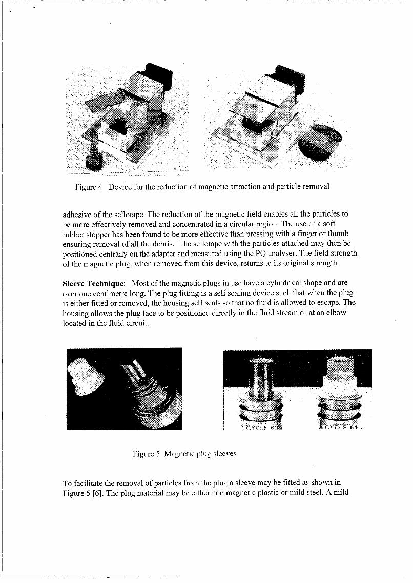
A device has been developed to both scrape the flank of the plug and at the same timereduce the magnetic attractive force at the plug face. This device is illustrated in theFigure 4.
The steps to remove the particles are simple. Firstly, the magnetic plug is located on aspring loaded seat, the 'jaws' of the clamp are then closed leaving the plug face proud ofthe clamp by several millimetres. Surrounding the plug with soft iron effectively reducesthe magnetic field - a reduction in excess of 80 per cent is achieved. A sellotape strip isplaced over the protruding plug end face and with pressure from the thumb the plug ispressed down on the spring loaded seat such that the plug flanks are scraped clean and allthese particles together with the particles attached to the plug face are attached by the
Figure 4 Device for the reduction of magnetic attraction and particle removal
adhesive of the sellotape. The reduction of the magnetic field enables all the particles tobe more effectively removed and concentrated in a circular region. The use of a softrubber stopper has been found to be more effective than pressing with a finger or thumbensuring removal of all the debris. The sellotape with the particles attached may then bepositioned centrally on the adapter and measured using the PQ analyser. The field strengthof the magnetic plug, when removed from this device, returns to its original strength.
Sleeve Technique: Most of the magnetic plugs in use have a cylindrical shape and areover one centimetre long. The plug fitting is a self sealing device such that when the plugis either fitted or removed, the housing self seals so that no fluid is allowed to escape. Thehousing allows the plug face to be positioned directly in the fluid stream or at an elbowlocated in the fluid circuit.
ii n CYF• -
Figure 5 Magnetic plug sleeves
To facilitate the removal of particles from the plug a sleeve may be fitted as shown inFigure 5 [6]. The plug material may be either non magnetic plastic or mild steel. A mild
steel sleeve has however, been found to be more effective. The mild steel sleeve maintainsa low level of magnetic attraction when removed from the magnetic plug. A slight tap ofthe sleeve is then sufficient to remove all the particles which may then be collected in asmall plastic cup. The PQ analyser then measures the ferrous content of the particles.
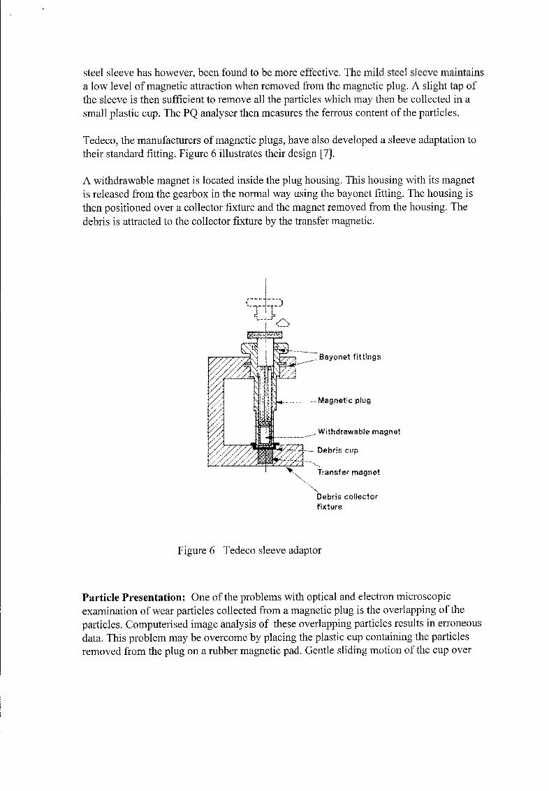
Tedeco, the manufacturers of magnetic plugs, have also developed a sleeve adaptation totheir standard fitting. Figure 6 illustrates their design [7].
A withdrawable magnet is located inside the plug housing. This housing with its magnetis released from the gearbox in the normal way using the bayonet fitting. The housing isthen positioned over a collector fixture and the magnet removed from the housing. Thedebris is attracted to the collector fixture by the transfer magnetic.
S... Bayonet fittings
Magnetic plug
.Withdrawabe magnet
-Debris cup
Transfer magnet
Debris collectorfixture
Figure 6 Tedeco sleeve adaptor
Particle Presentation: One of the problems with optical and electron microscopicexamination of wear particles collected from a magnetic plug is the overlapping of theparticles. Computerised image analysis of these overlapping particles results in erroneousdata. This problem may be overcome by placing the plastic cup containing the particlesremoved from the plug on a rubber magnetic pad. Gentle sliding motion of the cup over
the pad rearranges the particles in rows more suitable for microscopic examination (seeFigure 7).
A further advantage of this method is that the particles are unlikely to be altered bypressure as would be the case when pressure is applied to the sellotape to effect theadhesion between tape and particle.
Figure 7 Particle separation using a rubber magnetic pad
Wax Method [81: A further adaptation of the sleeve technique is the use of wax tosurround the plug after its removal from the housing.
Upon the removal of the magnetic plug, the end which has the debris attached is dippedinto molten wax and repeatedly dipped three or four times until a coating is formed in asimilar way to the formation of a wax candle. The wax bath would have been heated andmaintained at approximately 60 degrees C. The wax used in this evaluation was standardparaffin wax although it may be substituted for other waxes, resins or gels which are usedin model or investment casting.
The solid wax surrounding the magnetic plug may be slid along the plug until the capsuleis free of the plug. Removal of the wax is facilitated if the plug, after removal from thehousing, has not been cleaned with solvent. The oil retained on the surface of the plug actsas a release agent. The wax capsule within which the debris from the plug is embeddedmay then be accurately centred above the measuring head of the Ferrous Debris Monitor(PQ). This procedure avoids the operator optimising the debris position on the measuringinstrument.
If the debris has to be viewed by either optical or electron microscope it may be separatedfrom the wax by adding a small quantity of petroleum spirit in a suitable container.Agitation of the container facilitates the dissolution of the wax. A magnet held outside thecontainer allows the solution to be decanted leaving the particles free to be viewed. If a
gel or resin had been used then the appropriate solvent would be used. This may in somecases be water.
Conclusions: A number of methods for the removal of debris from magnetic drain plugshas been presented. These methods are at present being tested in the field and it is the fieldoperators who will judge the efficacy of debris removal and examination by thesemethods..
Acknowledgements: The help of colleagues at Swansea Tribology Services, theDepartment of Mechanical Engineering and Steve Greenfield of Vickers (Tedeco) Ltd isgratefully acknowledged.
References:
[1] Quantitative Debris Monitor - Tedeco - Vickers Systems.[2] Roylance; Developments in Wear Particle Analysis Using Computerised Procedures;Proc.I.Mech.E.,Aerotech '92 Conf.,C428/15/216.[3] Electron Solvent: Ecolink Inc. USA.[4] Hunt; Handbook of Wear Debris Analysis and Particle Detection in Liqueds, Elsevier1993.[5] Ferrous Debris Monitor (PQP), Analex, UK.[6] Patent 8910212 and GB.2232098 B (1989)[7] QDM Mk 11 Debris Analyser 1991 - Tedeco - Vickers Systems.[8] Patent pending.
Particle Transfer from Magnetic Plugs
Mervin H.JonesSwansea Tribology Services Ltd
University of Wales SwanseaSwansea, UK SA2 8PP
Abstract: Magnetic drain plugs have been in use for over thirty years and havedeveloped from simple magnets to self indicating devices. The purpose of this paper is toreview the debris transfer from the magnetic plug and suggest procedures to reduce theoperator effort, increase the efficiency of the debris transfer and to improve measurementrepeatability. Three new procedures are also proposed for review : the fitting of a plasticor metallic sheath, neutralisation of the magnetic attraction and the use of wax to removethe debris.
Keywords: Condition monitoring; magnetic drain plugs; wear debris analysis.
Introduction: Magnetic plugs have been in use for over thirty years and have developedfrom simple magnets to self indicating devices e.g. QDM - Quantitative Debris Monitor[1]. In many current applications, both civil and military, a standard magnetic plug whichhas to be removed from the system for visual inspection is still utilised and the method ofparticle transfer from the plug has basically remained unchanged : an initial solventcleaning process followed by an application of sellotape (Figure 1). Optical microscopyand X-Ray Fluorescence have enhanced particle recognition by determining the materialcomposition of the collected debris. The advent of computer imaging analysis, numericaland neural network analysis are currently generating expert systems to automaticallyclassify the wear debris generated during the wear process. [2].
It is the purpose of this paper to review the transfer procedures of the attached debris fromthe magnetic plug and suggest modifications to reduce the operator effort, increase theefficiency of the debris extraction and to improve measurement repeatability. Three newtechniques are also proposed for review : the fitting of a plastic or metallic sheath,neutralisation of the magnetic attraction and the use of wax to remove the debris.
Standard Sellotape Method: This method requires an initial cleaning of the magneticplug by a suitable solvent. The advent of the 'Montreal Protocol' for solvents and its
implementation have created difficulties due to the absence of an equally efficientalternative to the chlorinated hydrocarbons. Alternatives have
Figure 1 Typical magnetic plugs
however been proposed and accepted by the TSC of JOAP, Pensacola [3]. After removalof all traces of the lubricant or hydraulic fluid from the face of the magnetic plug a strip ofsellotape is pressed against the plug face and peeled away with the wear debris andcontaminants attached to the adhesive face of the sellotape. At this stage the tape isattached to a record card and may then be placed on a sensor which measures the ferrouscontent. This stage has posed numerous problems to the operator due to the positionsensitivity of the ferrous debris on the sensor. The following procedure is proposed whichovercomes this problem.
This procedure suggests the use of a light box' similar to the box used for viewingphotographic slides.
Once the debris has been 'wiped' from the magnetic plug using sellotape, the strip withthe attached debris may be positioned on the record card in the appropriate centralisedposition aided by the back-lighting from the light box. The debris is clearly visible in acentralised position and will obviate the presence of operator sensitivity and ensure amore consistent measurement when utilising a 'Wear Debris Tester instrument.' [4]
An alternative method which has shown superior sensitivity, more consistent and hencerepeatable results is the use of an adapter with the Ferrous Debris Monitor (ParticleQuantifier)[5]. The sellotape strip, with the extracted debris attached, as described above,is pressed on to the adapter shown in Figure 2. The debris is centred within the annulususing the light box method. The adapter is then placed on the Ferrous Debris Monitor for
measurement of the ferrous debris content with no further preparation (Figure 3).Repeated tests and rotation of the adapter have shown repeatability of better than 3 percent for the PQ Index.
Subsequent microscope examination of the debris is facilitated by the debris beingattached to the adhesive side of the sellotape. Auto focusing of the optical microscope ismaintained and viewing of the debris does not therefore have to be carried out through thesellotape, a procedure which distorts the image. Use of Mylar tape instead of the standardsellotape enables the particles to be prepared for electron microscope examination andXRF analysis without further treatment.
Reduction of Magnetic Attraction: Particles on the magnetic plug are often distributedaround the flank of the plug as well as on the face of the plug. In order to remove theseparticles the sellotape has to be wrapped around the flank. The attached debris oftenresults in an uneven particle distribution.
A device has been developed to both scrape the flank of the plug and at the same timereduce the magnetic attractive force at the plug face. This device is illustrated in theFigure 4.
The steps to remove the particles are simple. Firstly, the magnetic plug is located on aspring loaded seat, the 'jaws' of the clamp are then closed leaving the plug face proud ofthe clamp by several millimetres. Surrounding the plug with soft iron effectively reducesthe magnetic field - a reduction in excess of 80 per cent is achieved. A sellotape strip isplaced over the protruding plug end face and with pressure from the thumb the plug ispressed down on the spring loaded seat such that the plug flanks are scraped clean and allthese particles together with the particles attached to the plug face are attached by the
•:,v-".~~~I "2?:":': :i• i
Figure 4 Device for the reduction of magnetic attraction and particle removal
adhesive of the sellotape. The reduction of the magnetic field enables all the particles tobe more effectively removed and concentrated in a circular region. The use of a softrubber stopper has been found to be more effective than pressing with a finger or thumbensuring removal of all the debris. The sellotape with the particles attached may then bepositioned centrally on the adapter and measured using the PQ analyser. The field strengthof the magnetic plug, when removed from this device, returns to its original strength.
Sleeve Technique: Most of the magnetic plugs in use have a cylindrical shape and areover one centimetre long. The plug fitting is a self sealing device such that when the plugis either fitted or removed, the housing self seals so that no fluid is allowed to escape. Thehousing allows the plug face to be positioned directly in the fluid stream or at an elbowlocated in the fluid circuit.
Figure 5 Magnetic plug sleeves
To facilitate the removal of particles from the plug a sleeve may be fitted as shown inFigure 5 [6]. The plug material may be either non magnetic plastic or mild steel. A mild
steel sleeve has however, been found to be more effective. The mild steel sleeve maintainsa low level of magnetic attraction when removed from the magnetic plug. A slight tap ofthe sleeve is then sufficient to remove all the particles which may then be collected in asmall plastic cup. The PQ analyser then measures the ferrous content of the particles.
Tedeco, the manufacturers of magnetic plugs, have also developed a sleeve adaptation totheir standard fitting. Figure 6 illustrates their design [7].
A withdrawable magnet is located inside the plug housing. This housing with its magnetis released from the gearbox in the normal way using the bayonet fitting. The housing isthen positioned over a collector fixture and the magnet removed from the housing. Thedebris is attracted to the collector fixture by the transfer magnetic.
-,--"Bayonet fittings
Magnetic plug
WiXraai magnet
/ - -Debris cup
Transfer magnet
Debris collectorfixture
Figure 6 Tedeco sleeve adaptor
Particle Presentation: One of the problems with optical and electron microscopicexamination of wear particles collected from a magnetic plug is the overlapping of theparticles. Computerised image analysis of these overlapping particles results in erroneousdata. This problem may be overcome by placing the plastic cup containing the particlesremoved from the plug on a rubber magnetic pad. Gentle sliding motion of the cup over
the pad rearranges the particles in rows more suitable for microscopic examination (seeFigure 7).
A further advantage of this method is that the particles are unlikely to be altered bypressure as would be the case when pressure is applied to the sellotape to effect theadhesion between tape and particle.
Figure 7 Particle separation using a rubber magnetic pad
Wax Method [8]: A further adaptation of the sleeve technique is the use of wax tosurround the plug after its removal from the housing.
Upon the removal of the magnetic plug, the end which has the debris attached is dippedinto molten wax and repeatedly dipped three or four times until a coating is formed in asimilar way to the formation of a wax candle. The wax bath would have been heated andmaintained at approximately 60 degrees C. The wax used in this evaluation was standardparaffin wax although it may be substituted for other waxes, resins or gels which are usedin model or investment casting.
The solid wax surrounding the magnetic plug may be slid along the plug until the capsuleis free of the plug. Removal of the wax is facilitated if the plug, after removal from thehousing, has not been cleaned with solvent. The oil retained on the surface of the plug actsas a release agent. The wax capsule within which the debris from the plug is embeddedmay then be accurately centred above the measuring head of the Ferrous Debris Monitor(PQ). This procedure avoids the operator optimising the debris position on the measuringinstrument.
If the debris has to be viewed by either optical or electron microscope it may be separatedfrom the wax by adding a small quantity of petroleum spirit in a suitable container.Agitation of the container facilitates the dissolution of the wax. A magnet held outside thecontainer allows the solution to be decanted leaving the particles free to be viewed. If a
gel or resin had been used then the appropriate solvent would be used. This may in somecases be water.
Conclusions: A number of methods for the removal of debris from magnetic drain plugshas been presented. These methods are at present being tested in the field and it is the fieldoperators who will judge the efficacy of debris removal and examination by thesemethods..
Acknowledgements: The help of colleagues at Swansea Tribology Services, theDepartment of Mechanical Engineering and Steve Greenfield of Vickers (Tedeco) Ltd isgratefully acknowledged.
References:
[1] Quantitative Debris Monitor - Tedeco - Vickers Systems.[2] Roylance; Developments in Wear Particle Analysis Using Computerised Procedures;Proc.I.Mech.E.,Aerotech '92 Conf.,C428/15/216.[3] Electron Solvent: Ecolink Inc. USA.[4] Hunt; Handbook of Wear Debris Analysis and Particle Detection in Liqueds, Elsevier1993.[5] Ferrous Debris Monitor (PQP), Analex, UK.[6] Patent 8910212 and GB.2232098 B (1989)[7] QDM Mk 11 Debris Analyser 1991 - Tedeco - Vickers Systems.[8] Patent pending.