78
851-157 Rev. G Parts, Assembly & Maintenance Manual 3100 Series Flat Belt Conveyors
| Date post: | 13-Mar-2018 |
| Category: |
Documents |
| Upload: | hoangduong |
| View: | 215 times |
| Download: | 2 times |

851-157 Rev. G
Parts, Assembly& Maintenance
Manual
3100 SeriesFlat Belt Conveyors

2 3100 Series Flat Belt Conveyor Parts, Assembly and Maintenance Dorner Mfg. Corp.
Safe Practices 3. . . . . . . . . . . . . . . . . . . . . . . . . . . . . . . . . . . Foreword 3. . . . . . . . . . . . . . . . . . . . . . . . . . . . . . . . . . . . . . . . . Installation Instructions
Introduction 4. . . . . . . . . . . . . . . . . . . . . . . . . . . . . . . . . . . . . . .
General Instructions for All Conveyors 4. . . . . . . . . . . . . . . .
Special Instructions for End Driven Conveyors Over 13 ft (3965 mm) 5. . . . . . . . . . . . . . . . . . . . . . . . . . . . . .
Special Instructions for Center Driven Conveyors Over 13 ft (3965 mm) 6. . . . . . . . . . . . . . . . . . . . . . . . . . . . . .
All Sections Except 2nd Tail 6. . . . . . . . . . . . . . . . . . . . .
2nd Tail Installation 6. . . . . . . . . . . . . . . . . . . . . . . . . . . . .
End Drive Packages 8. . . . . . . . . . . . . . . . . . . . . . . . . . . . . . . .
Bottom Mount Installation & Initial Timing Belt Tension Adjustment 8. . . . . . . . . . . . . . . . .
Top Mount Installation & Initial Timing Belt Tension Adjustment 9. . . . . . . . . . . . . . . . .
Side Mount Installation 11. . . . . . . . . . . . . . . . . . . . . . . . .
Start-up & Preliminary AdjustmentsConveyor Belt Tension Adjustment 12. . . . . . . . . . . . . . . . . .
End-driven Conveyors 12. . . . . . . . . . . . . . . . . . . . . . . . .
Center-driven Conveyors 13. . . . . . . . . . . . . . . . . . . . . . .
Preliminary Belt Tracking Check 13. . . . . . . . . . . . . . . . . . . .
Conveyor Belt Tracking Adjustment Procedure 13. . . . . . . .
Center Drive Conveyor Belt Tracking Cam 14. . . . . . . . . . . .
Lubrication & MaintenanceLubrication 15. . . . . . . . . . . . . . . . . . . . . . . . . . . . . . . . . . . . . . .
3″ (76 mm) Pulley Bearings (Non-relubeable) 15. . . . .
Re-lubricating Twin 1″ (25 mm) Pulley Bearings 15. . .
Conveyor Belts 15. . . . . . . . . . . . . . . . . . . . . . . . . . . . . . . . . . .
Drive Components 15. . . . . . . . . . . . . . . . . . . . . . . . . . . . . . . .
Conveyor Hot Spots 15. . . . . . . . . . . . . . . . . . . . . . . . . . . . . . .
Cleaning Conveyor and Conveyor Belt 15. . . . . . . . . . . . . . .
Interface Tail Plate Twin 1 (25 mm) Pulley Removal & Bearing Repair 16. . . . . . . . . . . . . . . . . . . . . . . .
Top or Bottom End Drive Timing Belt Replacement & Operating Tension Adjustment 18. . . . . . . . . . . . . . . . . . . . .
Center Drive Timing Belt Replacement & Operating Tension Adjustment 18. . . . . . . . . . . . . . . . . . . . .
Conveyor Belt Replacement & AdjustmentsConveyor Belt Replacement 20. . . . . . . . . . . . . . . . . . . . . . . .
General Information 20. . . . . . . . . . . . . . . . . . . . . . . . . . .
Low-sided Conveyor Guiding 20. . . . . . . . . . . . . . . . . . .
High-sided Conveyor Side Wipers 20. . . . . . . . . . . . . . .
End-driven Conveyors 20. . . . . . . . . . . . . . . . . . . . . . . . .
Releasing Conveyor Belt Tension 20. . . . . . . . . . . .
Belt Removal 21. . . . . . . . . . . . . . . . . . . . . . . . . . . . . .
Belt Replacement 21. . . . . . . . . . . . . . . . . . . . . . . . . .
Center-driven Conveyors 22. . . . . . . . . . . . . . . . . . . . . . .
Preferred Method of Conveyor Belt Removal & Replacement 22. . . . . . . . . . . . . . . . . . .
Alternate Method for Re-threading Conveyor BeltThrough Center Drive Module 23. . . . . . . . . . . . . . .
All Center Drive Conveyors 23. . . . . . . . . . . . . . .
Belt Removal on Horizontal Center DriveConveyors Only 24. . . . . . . . . . . . . . . . . . . . . . . . .
Belt Removal on Vertical Center Drive
Conveyors Only 24. . . . . . . . . . . . . . . . . . . . . . . . .
Belt Fusing and System Restoration 25. . . . . . .
Troubleshooting GuideBearings 26. . . . . . . . . . . . . . . . . . . . . . . . . . . . . . . . . . . . . . . . .
Gearmotor 26. . . . . . . . . . . . . . . . . . . . . . . . . . . . . . . . . . . . . . .
Gear Reducers 26. . . . . . . . . . . . . . . . . . . . . . . . . . . . . . . . . . .
Vertical Center Drive Timing Belt 26. . . . . . . . . . . . . . . . . . . .
Conveyor Belt 28. . . . . . . . . . . . . . . . . . . . . . . . . . . . . . . . . . . .
Tool Kit 29. . . . . . . . . . . . . . . . . . . . . . . . . . . . . . . . . . . . . . . . . .
Replacement PartsConveyor Belt Part Number 30. . . . . . . . . . . . . . . . . . . . . . . . Intermediate Sections 31. . . . . . . . . . . . . . . . . . . . . . . . . . . . .
Tail Assemblies
Fixed End for 3″ (70 mm) Pulley 34. . . . . . . . . . . . . . . . .
Fixed End for 1″ (25 mm) Pulleys 36. . . . . . . . . . . . . . . .
Drive End 38. . . . . . . . . . . . . . . . . . . . . . . . . . . . . . . . . . . .
Tension End for 3″ (70 mm) Pulley 40. . . . . . . . . . . . . .
Tension End for 1″ (25 mm) Pulleys 42. . . . . . . . . . . . .
End Drive Gearmotor Mounting Packages
Bottom Mounting 44. . . . . . . . . . . . . . . . . . . . . . . . . . . . . .
Side Mounting 45. . . . . . . . . . . . . . . . . . . . . . . . . . . . . . . .
Top Mounting 46. . . . . . . . . . . . . . . . . . . . . . . . . . . . . . . . .
Center Drive Modules
Vertical
Visual Index 47. . . . . . . . . . . . . . . . . . . . . . . . . . . . . . .
Side Plates, Covers and Guards 48. . . . . . . . . . . . .
Belt Tensioning and Idler Pulley 50. . . . . . . . . . . . . .
Drive Pulleys, Timing Belt Pulleys & Mounting Plates 52. . . . . . . . . . . . . . . . . . . . . . . .
Horizontal Heavy Load
Visual Index 55. . . . . . . . . . . . . . . . . . . . . . . . . . . . . . .
Side Plates, Covers and Guards 56. . . . . . . . . . . . .
Belt Tensioning and Idler Pulley 58. . . . . . . . . . . . . .
Drive Pulleys, Poly-V Belt Pulleys & Mounting Plates 60. . . . . . . . . . . . . . . . . . . . . . . .
Horizontal Standard Load
Visual Index 63. . . . . . . . . . . . . . . . . . . . . . . . . . . . . . .
Side Plates, Covers and Guards 64. . . . . . . . . . . . .
Belt Tensioning and Idler Pulley 66. . . . . . . . . . . . . .
Drive Pulleys, Poly-V Belt Pulleys & Mounting Plates 68. . . . . . . . . . . . . . . . . . . . . . . .
Gearmotors, Motors & Controllers and Gearheads 70. . . . .
SAE Hardware Conversion Table 73. . . . . . . . . . . . . . . . . .
Numerical Index 74. . . . . . . . . . . . . . . . . . . . . . . . . . . . . . . .
Table of Contents

Dorner Mfg. Corp. 3100 Series Flat Belt Conveyor Parts, Assembly and Maintenance 3
ÇÇÇÇ
ÇÇ
•The safety alert symbol, black triangle with white exclamation, is used to alert you to potential personal injuryhazards.
•Standing on a conveyor or transporting people is prohibited.•When conveyors are used in conjunction with other equipment or as part of a multiple conveyor system, check
for potential pinch points and other mechanical hazards before system start-up. Because Dorner Mfg. Corp.cannot control the physical installation and applications of multiple conveyor systems, taking protective mea-sures is the responsibility of the user.
•Operating Dorner conveyors in an explosive environment is prohibited.•NEVER operate equipment without guards or other protective devices properly secured in place. In addition,
to prevent injury, make sure all electrical and pneumatic power sources have been disconnected and locked-out before you perform any maintenance, make any adjustments or replace any components.
•Some gearmotors may operate at an elevated temperature which may cause people to be startled if they acci-dentally touch the motor housing.
•Before proceeding to loosen hardware that locks-in the selected stand height, be sure that all related Conveyorsections are securely supported to prevent them from moving suddenly and dropping-down which may pinchor strike you, causing serious personal injury.
Use extreme caution when using the TailInstallation Tools. Refer to the specialDanger warning on page 6.
Ç Ç������
ForewordBy following the maintenance and adjustment instructions inthis manual, you will prolong the life of your conveyor andmaintain its maximum efficiency.
When ordering replacement parts, always give the model andserial number. These numbers are stamped on a nameplatelabel (Figure 1), located on conveyor side rail. Record thenumbers below for ready reference.
Model Number
(Fill In)
Serial Number
(Fill In)
For pictorial clarity, some illustrations in this manual mayshow guards or other protective devices open or removed.Under no circumstances should the conveyor be operatedwithout these devices securely in place.
NOTE:All technical data in this publication is based on the prod-uct information available at time of printing. All assemblypart numbers are listed for metric mounting hardware.Instructions for installation, adjustment and mainte-nance are the same for metric and SAE style conveyors.SAE parts are identified by using the metric part num-bers listed and dropping the “M” suffix. Refer to the tableon page 73 for SAE equivalent hardware.
Figure 1: Typical Model & Order Number Nameplate Label PZ01
Safe Practices

4 3100 Series Flat Belt Conveyor Parts, Assembly and Maintenance Dorner Mfg. Corp.
IntroductionDorner Mfg. Corp. makes every effort to properly package andship its products. Upon receipt, inspect all packages for anyshipping damage. Notify the carrier immediately, when problemsare first discovered. Compare the shipment with the packing slipand contact the factory about any discrepancies (see back page forphone number). Check the individual assembly instructions(provided) for drive and accessory component completeness.
NOTE:Some packages may have been separated by carrierduring shipment.
3100 series flat belt conveyors are engineered, designed andmanufactured to meet a variety of material handling applica-tions.
All conveyors feature an extruded aluminum alloy frame,T-slots for convenient mounting of pre-engineered accesso-ries and bearings and gearmotor drive packages designed fordependable and low maintenance operation.
To compliment the features and functions of 3100 series flat-beltconveyors, any conveyor can be combined with standardaluminum support stands or steel support stands. Both types ofstands are available with fixed or swivel casters.
Use Dorner stands and compatible mounting hardware orother suitable mounting arrangements, provided by the user,to squarely, straightly and securely support the conveyor.Refer to the Metric Support Stands and Conveyor MountingsParts, Assembly & Maintenance Manual for additionaldetails. When properly set-up, the conveyor must be free ofany twist, regardless of overall conveyor length or width.
General Instructionsfor All Conveyors
1. Using appropriate lifting means, carefully remove theconveyor assembly or section from the wooden ship-ping box and place it in its correct operating positionand direction.
2. Use Dorner stands and compatible mounting hardwareor mounting provided by the user to securely mount theconveyor. Refer to Metric Support Stands and Convey-or Mountings Parts, Assembly & Maintenance Manualfor appropriate mounting details.
3. The conveyor must be mounted straight, flat and level,within the confines of the conveyor. Always use botha straight edge and a level for initial set up (Figure 2).
IMPORTANT:Do not bend or twist the conveyor frame when mountingthe conveyor.
Figure 2: Conveyor Alignment ReferenceDetail
0377
4. Make sure that intermediate sections and tail assem-blies are butted tightly together and securely fastened.
5. For all end-driven conveyors, refer to the “End DrivePackages” topic, starting on page 8, to attach gearmotor.For maximum load carrying, locate the gearmotor so thatwhat is being conveyed moves toward the drive.
6. Some gearmotors will require some customer-providedelectrical wiring. Follow all applicable local electricalcodes and the wiring diagrams, supplied with the gearmo-tors. The wiring diagram, for a three-phase gearmotor, islocated inside the terminal box which is attached to thegearmotor. The wiring diagram for a variable speedgearmotors is located inside the control box.
7. All low side conveyors without optional guiding, havefactory installed belt tracking guides, 200524 (A of Figure3) installed on both ends of conveyor. The guide is a 3.5″(89 mm) long piece of formed plastic which snaps onto theportion of the conveyor sidewall (B) above the T-slotchannel.
a. To remove the guide from the conveyor side-wall, apply a slight outward and downwardfinger-pressure on one of the top corners of theguide and gradually peel it off the portion of theconveyor sidewall (B).
b. To install the guide onto the conveyor sidewall,first place the lower lip (C), of the guide, againstthe upper edge of the conveyor sidewall T-slotchannel. Then, apply inward and upward pres-sure to completely snap it into place.
Installation Instructions

Dorner Mfg. Corp. 3100 Series Flat Belt Conveyor Parts, Assembly and Maintenance 5
NOTE:Be sure to save the belt tracking guides (A of Figure 3)for start-up after belt cleaning or replacement.
Figure 3: Conveyor Low SideBelt Tracking Guide Installation Detail
A
0088b
B
B
C
C
Special Instructions for End DrivenConveyors Over 13 ft (3965 mm)
NOTE:The following special field setup procedures are pro-vided for and apply only to an End Drive Conveyor whichis longer than 13 ft (3965 mm).
All end-driven conveyors are manufactured with endlessconveyor belts. Conveyors over 13 ft (3965 mm) long areconfigured and built at the factory, partially disassembled,
crated and shipped in sections. The customer must re-as-semble the sections and tension the conveyor belt. Thefollowing procedure is recommended.
1. Position stands, with the return roller/mounting assem-blies attached, in proper locations to support the driveend, frame split and tail end. For additional details,refer your Metric Support Stands and ConveyorMountings Parts, Assembly & Maintenance Manual.
2. Place belt around the assembled drive/intermediate section.Push the lower return run of the belt up into the conveyorframe, when lowering the section onto the return roller/mounting assembly, to prevent pinching the belt.
NOTE:On the underside of the conveyor, the belt rides on thereturn rollers. The rollers MUST be perpendicular to theconveyor belt and rotate freely, at all times.
3. Clamp drive/intermediate section to the stands withreturn roller/mounting assemblies.
4. Unroll the belt toward the tail end of the conveyor.
5. Install the tension end tail section into the intermediatesection end, if not already assembled.
6. Place both sections inside the conveyor belt loop. Toprevent pinching the conveyor belt, make sure the returnrun of the belt is tucked-up into the conveyor frame whilethe conveyor is being set down and onto the returnroller/mounting assembly. Fasten sections together usingconnecting mounting assemblies.
NOTE:Match-marked numbers must be re-installed in proper order.
7. Clamp all intermediate/tail sections to the support stands.
8. Set the conveyor belt tension. Refer to “Conveyor BeltTension Adjustment” topic beginning on page 12.
Installation Instructions

6 3100 Series Flat Belt Conveyor Parts, Assembly and Maintenance Dorner Mfg. Corp.
Special Instructions for CenterDrivenConveyors Over 13 ft (3965 mm)
NOTE:The following special field setup procedures are pro-vided for and apply only to a Center Drive Conveyorwhich is longer than 13 ft (3965 mm).
All Sections (Except 2nd Tail)All Center Drive conveyors are manufactured with endless belts.Conveyors over 13 ft (3965 mm) long are configured and builtat the factory, partially disassembled, crated and shipped insections. The customer must reassemble the sections and tensionthe conveyor belt. The following procedure is recommended.
1. Position stands, with the return roller/mounting assem-blies attached, in proper locations.
2. Place the intermediate section with the drive unit intoposition on the stand mounting brackets with returnrollers.
3. Unroll the belt toward the shortest end of the conveyor,using enough belt for that distance.
4. Place all of the sections inside the conveyor belt loop. Toprevent pinching the conveyor belt, make sure the returnrun of the belt is tucked-up into the conveyor frame whilethe conveyor is being set down and onto the returnroller/mounting assembly. Fasten sections together usingconnecting mounting assemblies.
5. Clamp to the stands.
NOTE:On the underside of the conveyor, the belt rides on thereturn rollers. The rollers MUST be perpendicular to theconveyor belt and rotate freely, at all times.
6. Continue this process, one section at a time, until the
second of the two tail sections is to be installed. Installthe 2nd tail section per the following instructions.
2nd Tail Installation
ÇÇ
ÇÇÇÇ
������
The Tail Installation Tools are used duringinitial conveyor setup or when conveyorbelt is being replaced. BE SURE, whileyou are rotating the tail section intoposition, to keep your fingers out frominside the belt loop and from the insideend of the tail section (shaded area ofdrawing).
Tail Section
Belt Loop
Conveyor
Two tail installation tools, part numbers 300362M (D ofFigure 4), must be used on some center drive conveyors thatare 13 ft (3965 mm) and longer, to get the 2nd tail sectionassembled inside the conveyor belt loop. These tools areprovided with all center drive conveyors over 13 ft (3965 mm)long.
1. Begin by removing the screws (E) which are securingthe four T-bars (F) to the tail section (G).
Installation Instructions

Dorner Mfg. Corp. 3100 Series Flat Belt Conveyor Parts, Assembly and Maintenance 7
Figure 4: Tail Installation Tool Detail
0417
E
F
D
G F
D0.375”(10 mm)
2. Slide T-bars into the proper T-slots at the end ofconveyor frame.
3. Attach the tail installation tools tightly to the upperT-bars on both sides of the conveyor frame. The toolsare to extend approximately 0.375″ (10 mm) beyondthe end of the conveyor frame.
NOTE:The hex nuts, on the tail installation tool, are used onlyto secure the washer during storage.
4. Place the tail section (G of Figure 5) on top of theconveyor and inside the belt loop as shown.
Figure 5: Tail Section Positioning Detail
0419
G
I
5. Rotate the tail installation tools around the shoulder screws(I), until the pins on the tools engage the holes in the tailsection (used for mounting the upper T-bar).
6. Very carefully rotate the tail section down into position.Install the tail cover plate screws (J of Figure 6) throughthe tail cover plates into the lower T-bars. Screws are tobe snug, but not tight at this time; screws will be tightlysecured after proper conveyor belt tracking is adjusted.
7. Remove the tail installation tools. Slide the upperT-bars (K) under the tail cover plates. Install the uppercover plate screws.
8. After conveyor re-assembly is complete, loosen thescrews at intermediate and tail/intermediate joints.
9. Align and bring all joints together and tighten allconnecting hardware. For additional details, refer yourMetric Support Stands and Conveyor Mountings Parts,Assembly & Maintenance Manual.
10. The pneumatic belt take-up system will tighten the beltwhen air pressure is applied. The pressure gauge is setand locked at the factory for start-up tensioningpressure. Add pressure, as required, to convey the loadwithout stalling. Do not use excessive pressure.
11. Proceed to the “Start-up & Preliminary AdjustmentsProcedure” section, beginning on page 12.
Figure 6
J
K
0418
Installation Instructions

8 3100 Series Flat Belt Conveyor Parts, Assembly and Maintenance Dorner Mfg. Corp.
End Drive Packages
NOTE:For maximum load carrying, locate the gearmotor sothat what is being conveyed moves toward the drive.
Bottom Mount Installation & Initial TimingBelt Tension Adjustment
The bottom mount package can be set up in either one of twopositions (A or D of Figure 7).
Figure 7: Bottom Drive Mounting Detail
Position A
1
2
Position D
1
2
03420343
The conveyor belt can be driven in either one of two directions(1 or 2 of Figure 7). Arrows show belt travel direction.
1. Refer to Figure 9 and attach the gearmotor (E) and themotor mounting plate (H) to the conveyor (F) usingone M6 x 30 mm socket head cap screw (I) in the topmounting hole of the mounting plate, two M6 x 16mm socket head cap screws (J) in middle holes andthree M6-1.0 x 20 mm socket head cap screws (K) inbottom holes.
2. Assemble the drive and driven pulleys (M and/or L) andtiming belt (N). Place a square key (O of Figure 9) intothe keyway on the gearmotor and conveyor shafts. Installthe pulleys so that the timing belt is centered on the belttensioning roller assembly (B of Figures 8 & 9) and thepulleys are in line with each other. Tighten the pulley setscrews (Q of Figure 9) or Taper Lock� bushing screws
(P), which fasten the pulleys to the shafts. Determinewhich direction the conveyor belt is traveling and positionthe tensioning roller assembly on slack side of the timingbelt (Figure 8).
3. Adjust timing belt tension by loosening the M12 x 25mm socket head cap screw (R of Figure 9) and slidingthe belt tensioning roller assembly against the belt.Tension should be measured at mid-point (C of Figure8) on the tension side of the timing belt. As a startingpoint for the tensioning process, there should be a 1/8″(3 mm) deflection with 6 lb (3kg or 26 N) of force.
B
B
Figure 8: Bottom Drive Timing BeltAdjustment Detail
2
C
1
0294 0295
C
4. Every timing belt application exhibits its own individualoperating characteristics. The optimum timing belt ten-sion should be determined experimentally.
If necessary, continue to slide the tensioning rollerassembly against the timing belt until the belt istensioned so as to prevent jumping of teeth under themost severe conditions which the drive will encounter.Tighten the M12 x 25 mm socket head cap screw aftertension requirements are achieved.
IMPORTANT:Do not over tension the timing belt. Over tensioning maycause reduced belt life or bearing and drive damage.
5. Attach the bottom drive cover (S of Figure 9) using fourM4 x 10 mm button head cap screws (T).
Installation Instructions
Dorner Mfg. Corp. 3100 Series Flat Belt Conveyor Parts, Assembly and Maintenance 9
E
F
I J
K
H
O
O
B
P
L
LP
M
Q
T
SN
G
R
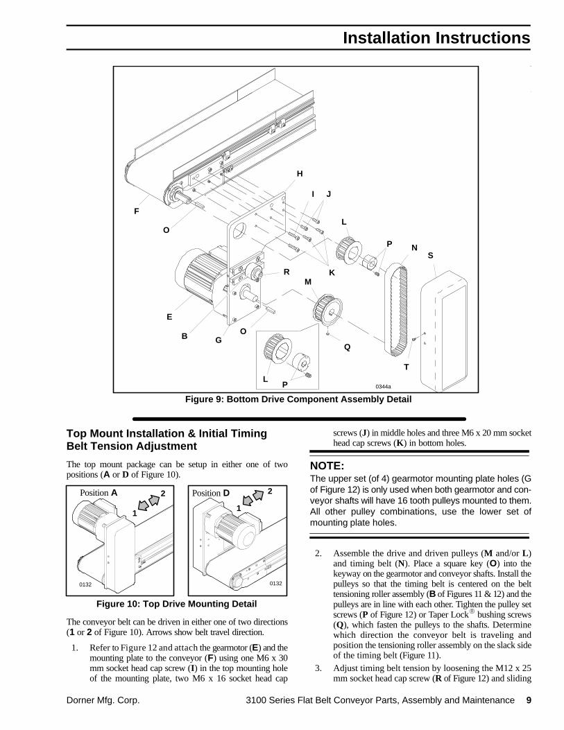
Figure 9: Bottom Drive Component Assembly Detail
0344a
Top Mount Installation & Initial TimingBelt Tension Adjustment
The top mount package can be setup in either one of twopositions (A or D of Figure 10).
Position A
1
2 Position D
Figure 10: Top Drive Mounting Detail
1
2
0132 0132
The conveyor belt can be driven in either one of two directions(1 or 2 of Figure 10). Arrows show belt travel direction.
1. Refer to Figure 12 and attach the gearmotor (E) and themounting plate to the conveyor (F) using one M6 x 30mm socket head cap screw (I) in the top mounting holeof the mounting plate, two M6 x 16 socket head cap
screws (J) in middle holes and three M6 x 20 mm sockethead cap screws (K) in bottom holes.
NOTE:The upper set (of 4) gearmotor mounting plate holes (Gof Figure 12) is only used when both gearmotor and con-veyor shafts will have 16 tooth pulleys mounted to them.All other pulley combinations, use the lower set ofmounting plate holes.
2. Assemble the drive and driven pulleys (M and/or L)and timing belt (N). Place a square key (O) into thekeyway on the gearmotor and conveyor shafts. Install thepulleys so that the timing belt is centered on the belttensioning roller assembly (B of Figures 11 & 12) and thepulleys are in line with each other. Tighten the pulley setscrews (P of Figure 12) or Taper Lock� bushing screws(Q), which fasten the pulleys to the shafts. Determinewhich direction the conveyor belt is traveling andposition the tensioning roller assembly on the slack sideof the timing belt (Figure 11).
3. Adjust timing belt tension by loosening the M12 x 25mm socket head cap screw (R of Figure 12) and sliding
Installation Instructions

10 3100 Series Flat Belt Conveyor Parts, Assembly and Maintenance Dorner Mfg. Corp.
the belt tensioning roller assembly (B of Figures 11 &12) against the belt. Tension should be measured atmid-point (C of Figure 11) of on the tension side of thetiming belt. As a starting point for the tensioningprocess, there should be a 1/8″ (3 mm) deflection with6 lb (3kg or 26 N) of force.
B
Figure 11: Top Drive Timing BeltAdjustment Detail
B
21C
0297 0296
C
4. Every timing belt application exhibits its own individualoperating characteristics. The optimum timing belt ten-sion should be determined experimentally.
If necessary, continue to slide the tensioning rollerassembly against the timing belt until the belt istensioned so as to prevent jumping of teeth under themost severe conditions which the drive will encounter.Tighten the M12 x 25 mm socket head cap screw aftertension requirements are achieved.
IMPORTANT:Do not over tension the timing belt. Over tensioning maycause reduced belt life or bearing and drive damage.
5. Attach the top drive cover (S of Figure 12) using fourM4 x 10 mm button head cap screws (T).
Figure 12: Top Drive Component Assembly Detail
H
M
T
S
J
P
R
O
O
K
I
L
N
Q
L
Q
F
E
GB
0347a
C
Installation Instructions

Dorner Mfg. Corp. 3100 Series Flat Belt Conveyor Parts, Assembly and Maintenance 11
Side Mount Installation The side mount package can be set up in either one of twopositions (A or D of Figure 13).
Position A
1
2
Position D
1
2
Figure 13: Side Drive Mounting Detail
0348a 0349a
In addition, the conveyor belt can be driven in either one of twodirections (1 or 2 of Figure 13). Arrows show belt traveldirection.
Loose components shipped with the mounting kit include thesquare key (K of Figure 14), M6 x 20 mm, M6 x 25 mm andM6 x 35 mm socket head cap screws (L, M & N), side driveguard (O) and M5 x 10 mm button head cap screws (P).
1. Secure the gearmotor (J) and the mounting plateassembly to the conveyor (I) using one M6 x 35 mmsocket head cap screw (N) in top mounting hole, two
M6 x 20 mm socket head cap screws (L) in middle holesand three M6 x 25 mm socket head cap screws (M) inthe bottom holes.
2. The flex coupling (R) is shipped attached to thegearmotor shaft (F). Make sure the set screw (H) on theend farthest from the gearmotor is loosened far enoughto allow the coupling to slide onto the outboard shaft(E) on the conveyor.
3. Mount the assembly to the conveyor by placing thesquare key (K) into the keyway on the outboard shaftand sliding the flex coupling onto the shaft as far as thekey will allow.
4. While holding the gearmotor and flex coupling assem-bly in alignment, secure the gearmotor to the mountingplate using the four M6 x 20 mm head cap screws.
NOTE:Flex coupling is provided to compensate for maximumshaft misalignments (G) of up to 1/16″ (1.5 mm).
5. Tighten the set screws on the flex coupling and re-as-semble the side drive guard (O) to the mounting plateusing the M5 x 10 mm button head cap screws (P).
Figure 14: Side Drive Component Assembly Detail
F
G
E
M
R
P
S
Q
K N
O
L
J
I
H
0350 0351b
Installation Instructions

12 3100 Series Flat Belt Conveyor Parts, Assembly and Maintenance Dorner Mfg. Corp.
Conveyor Belt Tension Adjustment
IMPORTANT:The conveyor belt is the single most important compo-nent of a 3100 Series conveyor. Therefore, Dorner rec-ommends that both correct conveyor belt tension andproper belt tracking be correctly established before theconveyor is put into operation.
End-driven Conveyors The following procedure is used to tension the conveyor beltfor end driven conveyors. An end-driven conveyor uses a rackand pinion assembly (G of Figure 15) to take up conveyor beltslack and achieve proper conveyor belt operating tension. Toadjust the belt tension:
0353
DB
A
F
Figure 15
G
C
E
1. Locate the tension end (B) of the conveyor, identifiedwith a label (C).
2. Make sure that the belt tracking cam assemblies (D), oneach side of the conveyor, are secure. Refer to calloutD of Figure 18 on page 14, for more details.
3. Then, loosen tail cover plate clamping screws (E) onboth sides of the tension end.
4. Insert a 5 mm hex key wrench (F) into either end of thepinion (A).
5. Rotate the pinion to extend the tensioning end and applya sufficient tension to eliminate drive pulley slippage.
NOTE:Over-tensioning conveyor belt adds unnecessary load-ing to the pulley bearings.
6. While holding the pinion in the tensioned position, tightencover plate screws on both sides of the conveyor. Torquethe mounting screws to approximately 18 in-lb (2 Nm).
Start-up & Preliminary Adjustments

Dorner Mfg. Corp. 3100 Series Flat Belt Conveyor Parts, Assembly and Maintenance 13
Center-driven Conveyors
The belt tension for all center drive conveyor belts isestablished and maintained by the regulator adjusted (H ofFigure 16 or Figure 17) air pressure to the take-up cylinder. Airpressure should initially be set to 55 PSIG (385 kPa) andre-adjusted so that the belt under maximum load does not slip.Conveyor belt tension should be adequate to prevent slippagewhich could result in the drive pulley wearing/burning-throughthe conveyor belt. Conversely, belt tension should not be toogreat which could stretch the belt and cause undue bearingstress and early failure.
NOTE:Dorner recommends that the system supply be at least55 PSIG (385 kPa) of 10 micron filtered air pressure.
Figure 16: Vertical Center Drive
H
Figure 17: Horizontal Center Drive
H
Preliminary Belt Tracking Check
IMPORTANT:Stop the conveyor immediately if the belt does not trackproperly. Refer to the “Conveyor Belt Tracking Adjust-ment procedure” topic beginning on the next page.
1. Make sure the conveyor belt tension is set properly.Refer to “Conveyor Belt Tension Adjustment” topicbeginning on the preceding page.
2. Make sure the belt tracking guides are installed on thedischarge end of low side conveyors, as applicable (seepage 5).
3. Energize the power to the conveyor drive motor and, oncenter-driven conveyors only, turn on the supply air tothe take-up cylinder. Then, proceed as follows:
a. On fixed speed conveyors, jog the conveyor onand off in very short cycles, a maximum of 6starts per minute. Observe the belt tracking onboth ends. Gradually increase the run cycle.
b. On variable speed conveyors, set the control atits lowest speed. Run the conveyor and observethe belt tracking at both ends.
4. Make additional tracking adjustments, as needed, perthe following topic.
Conveyor Belt TrackingAdjustment ProcedureMake sure the belt is properly tensioned and that the conveyoris straight and level in all directions within the confines of theconveyor.
This conveyor is equipped with an articular linkage whichallows the pulley to be positioned at a slight angle to facilitatebelt tracking.
If you are working on a low side conveyor, re-install the belttracking guides following the details on page 5.
Check both ends of the conveyor for proper belt tracking. Thebelt should track centered between the tail plates on both endsof the conveyor. Conveyor belt tracking should always beadjusted on the discharge end of conveyor first. Then, checkthe tracking on the opposite (infeed) end of the conveyor andreadjust, if necessary.
To adjust belt tracking:
1. Loosen (but do not remove) the two cam clamping platescrews (I) on both sides of the conveyor discharge.
2. Slide both belt tracking cam assemblies (D of Figure18) as far as they can be moved toward the end of theconveyor.
3. The belt tracking cam (J) must be set to the low pointat the point of contact as illustrated. The slot (K), in thebelt tracking cam, should be horizontal and pointingtowards the end of the conveyor.
Start-up & Preliminary Adjustments
14 3100 Series Flat Belt Conveyor Parts, Assembly and Maintenance Dorner Mfg. Corp.
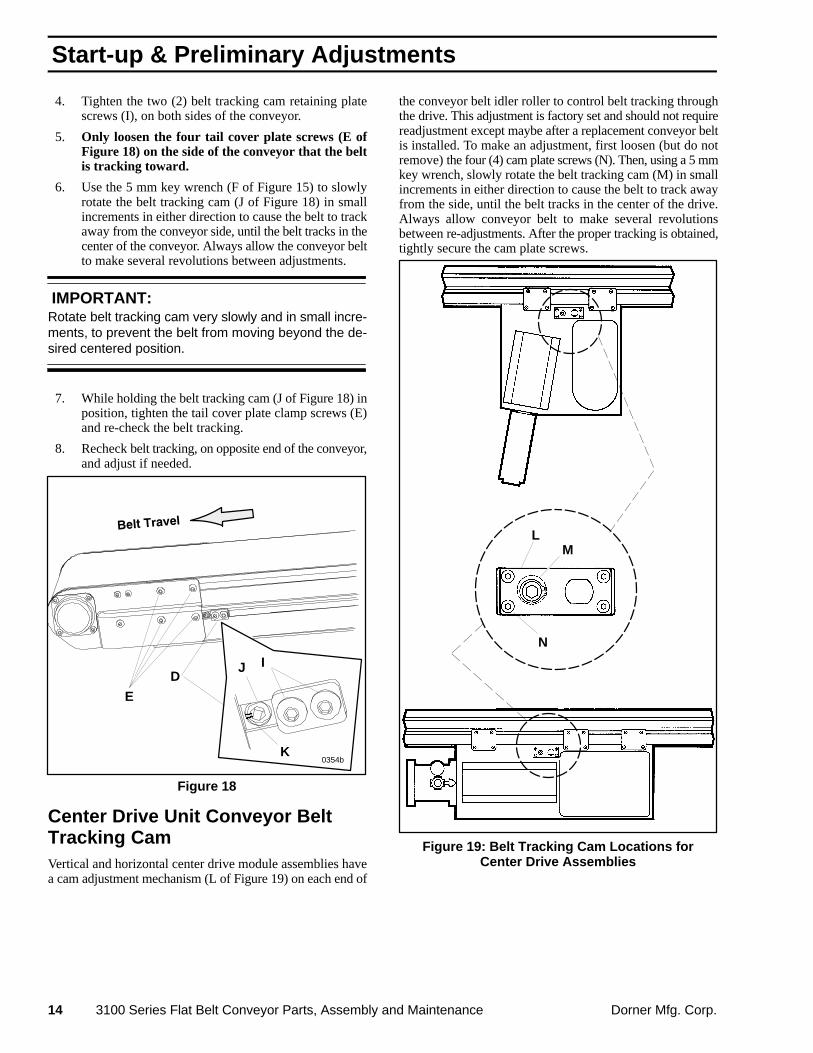
4. Tighten the two (2) belt tracking cam retaining platescrews (I), on both sides of the conveyor.
5. Only loosen the four tail cover plate screws (E ofFigure 18) on the side of the conveyor that the beltis tracking toward.
6. Use the 5 mm key wrench (F of Figure 15) to slowlyrotate the belt tracking cam (J of Figure 18) in smallincrements in either direction to cause the belt to trackaway from the conveyor side, until the belt tracks in thecenter of the conveyor. Always allow the conveyor beltto make several revolutions between adjustments.
IMPORTANT:Rotate belt tracking cam very slowly and in small incre-ments, to prevent the belt from moving beyond the de-sired centered position.
7. While holding the belt tracking cam (J of Figure 18) inposition, tighten the tail cover plate clamp screws (E)and re-check the belt tracking.
8. Recheck belt tracking, on opposite end of the conveyor,and adjust if needed.
Figure 18
ID
K
J
0354b
E
Center Drive Unit Conveyor BeltTracking CamVertical and horizontal center drive module assemblies havea cam adjustment mechanism (L of Figure 19) on each end of
the conveyor belt idler roller to control belt tracking throughthe drive. This adjustment is factory set and should not requirereadjustment except maybe after a replacement conveyor beltis installed. To make an adjustment, first loosen (but do notremove) the four (4) cam plate screws (N). Then, using a 5 mmkey wrench, slowly rotate the belt tracking cam (M) in smallincrements in either direction to cause the belt to track awayfrom the side, until the belt tracks in the center of the drive.Always allow conveyor belt to make several revolutionsbetween re-adjustments. After the proper tracking is obtained,tightly secure the cam plate screws.
Figure 19: Belt Tracking Cam Locations forCenter Drive Assemblies
L
N
M
Start-up & Preliminary Adjustments

Dorner Mfg. Corp. 3100 Series Flat Belt Conveyor Parts, Assembly and Maintenance 15
Dorner 3100 series flat belt conveyors are designed andmanufactured for long life and low maintenance. Mainte-nance consists of identifying a problem and taking correctiveaction, as identified below.
To prevent injury, make sure all electricaland pneumatic power sources have beendisconnected and locked-out before youperform any maintenance, make anyadjustments or replace any components.
Ç Ç
Lubrication
3″ (76 mm) Pulley Bearings(Not Re-greasable)
NOTE:All 3″ (76 mm) Pulley Bearings are sealed and are notre-greasable.
Twin 1″ (25 mm) Pulley Bearings
Lubricate the twin 1″ (25 mm) pulley bearings, on each sideof the conveyor, every 750 hours of operation or morefrequently, when conditions warrant. Use a conventionalhand-operated grease gun, with a maximum of one pump perapplication, unless otherwise specified. To prevent damage tothe bearing, do not use a power grease gun which createsundue pressure that may unseat the bearing. Use Dorner RedGrease 14 oz. cartridge, part number 829-002, or 14 oz. can,part number 829-003.
NOTE:Do not over-lubricate the twin pulley bearings.
Maintenance
Conveyor Belt
Inspect the conveyor belt for:
� Stalling or slipping; refer to “Conveyor Belt Tension”beginning topic on page 12.
� Tracking problems; refer to “Conveyor Belt TrackingAdjustment Procedure” beginning on page 13.
� Worn edges
� Surface cuts or wear
� Stretching or breaking
� Belt that walks to one side
� Non-uniform movement of the conveyor belt
� Lines or rough edges on belt
� Accumulated dirt
� Jammed parts
� Foreign material inside conveyor
� Interference with mounted accessories
Conveyor Hot SpotsInspect the conveyor frame and drive unit surfaces for hotspots which indicate the need for tracking the conveyor belt,replacing worn-out bearings and/or lubricating 1″ (25 mm)bearings (where applicable).
Drive ComponentsCheck drive timing or Poly-V belt for wear. Replace wornbelt, if necessary. Check the drive pulleys for properalignment and re-align, if necessary.
Cleaning Conveyor and Conveyor BeltDuring maintenance procedures involving conveyor belt orworn part replacement, be sure to thoroughly clean allconveyor surfaces, inside and out. Remove any compactedmaterial from the outer surfaces of all pulleys. Check allbearings and rollers for smooth operation.
IMPORTANT:Do not use belt cleaners that contain alcohol, acetone,Methyl Ethyl Ketone (MEK) or other harsh chemicals.
Use Dorner Belt Cleaner, part number 625619, or equivalent.Mild soap and water may also be used. Do not soak the belt.Due to the texture of woven polyester and black anti-staticbelts, use a small, semi-stiff bristled brush (similar to avegetable brush), to improve cleaning.
Lubrication & Maintenance

16 3100 Series Flat Belt Conveyor Parts, Assembly and Maintenance Dorner Mfg. Corp.
Twin 1″ (25 mm)Pulley Removal & Bearings ReplacementPulley Removal
1. Remove conveyor belt for access to the pulleys. Referto the appropriate topic in the “Conveyor Belt Replace-ment & Adjustment” section of this manual beginningon page 20.
2. Remove the tail cover plate screws (A of Figure 20) andtail cover plates (B) on both sides of the conveyor.
Figure 20
B
A
DC
EB
E
A0300
3. Remove the retaining sleeves (C) and pulley (D). Ifretaining sleeves are stuck or wedged tight, proceed to thenext step.
4. To remove a wedged sleeve, refer to Figure 21 andremove the grease fitting. Then, working through thegrease fitting hole (F of Figure 21) in the sleeve (C),form a puller arrangement as shown. Use the bearinganvil/sleeve removal tool 25-09 (G), washer 605279(H) and M6 x 35 mm socket head cap screw 920635M(I). All these parts are in Tool Kit on page 29.
5. Remove the pulley shaft (J) from the pulley (D) andreplace the pulley bearing. See “Bearing Removal”subtopic on this page.
Figure 21
DG
FC
I
H
J
Bearing Replacement
Bearing Removal
Use the following procedure to remove pulley bearings:
1. Make sure that the shoulder (M) on the bearing removaltool is completely closed. If it is slightly open it may notfit into the bearing (P of Figure 23). Use the hex keywrench extension tool (N of Figure 23), (part number25-08, item 23 of Tool Kit 2500M on page 29) andloosen the tapered screw (L of Figure 22) whilecompressing the flair (M) inward to make sure that thetool is completely closed.
K
ML
0070A.IL
Figure 22: Bearing Removal Tool
2. Insert bearing removal tool (O of Figure 23) into thepulley (Q) through bearing (P).
Lubrication & Maintenance

Dorner Mfg. Corp. 3100 Series Flat Belt Conveyor Parts, Assembly and Maintenance 17
N
O
Q
P
0070B.IL
Figure 23
3. While holding the hex key wrench extension tool (N ofFigure 24), rotate bearing removal tool using flats (O)to tighten the bearing removal tool’s tapered screw (R)until the flair (S) of the tool is completely spread openbehind the bearing (P).
0070C
Figure 24
N
O
RS
PT
U
4. Support pulley end (T) with bearing anvil/sleeveremoval tool (U), (part number 25-09, item 18 of ToolKit 2500M on page 29). Using an arbor press or drillpress, press against the extension tool (N) until bearingdrops into anvil/sleeve removal tool (U).
IMPORTANT:Heavy tapping or hammering will damage the bearingand/or hex key wrench extension tool.
Bearing Replacement
Use the following procedure to install new pulley bearings:
1. Hold the pulley (D of Figure 25) in an upright positionwith “V” block or other means. Support the bottom endof pulley (D) using anvil/sleeve removal tool (U).
NOTE:Always keep the bearings (F) and pulleys (D) aligned dur-ing installing. Misalignment will tilt the bearing and dam-age it.
2. With an arbor press or drill press, align the bearinginsertion tool (V), (part number 25-10, item 22 of ToolKit 2500M on page 29) with the pulley bore (W).
3. Slide the bearings (F) onto the bearing insertion tool(V).
4. Press bearing (F) firmly and slowly into pulley (D) untilit bottoms out on pulley shoulder (X). If bearing fits tooloosely in the pulley bore (W) or if the bore is out ofround, the entire pulley assembly must be replaced.
D
V
W
X
0071
Figure 25
F
Pulley Replacement
Replace a repaired pulley or install a new pulley as follows:
1. Insert pulley shaft (J of Figure 21) into the pulley (D).
2. Insert pulley (D of Figure 20) between the tail pulleyplates (E).
3. Slide the retaining sleeves (C) through openings in the tailpulley plates (E) and into both sides of the pulleys (D).
4. Replace and re-secure the tail cover plates (B) byinstalling and securing the tail cover plate screws (A)and on both sides of the conveyor.
5. Re-install the conveyor belt. Refer to the “Conveyor BeltReplacement & Adjustments” section starting on page 20.
Lubrication & Maintenance

18 3100 Series Flat Belt Conveyor Parts, Assembly and Maintenance Dorner Mfg. Corp.
Top or Bottom Mount End DriveTiming Belt Replacement& Operating Tension Adjustment Proceed as follows:
1. Before proceeding, disconnect and lockout electricalpower to the drive motor. Then, remove the drive cover.
2. Check the condition of the existing timing belt andreplace if worn. As necessary, loosen the belt tensioningroller assembly (A of Figure 26) to remove worn belt.
3. Install the new timing belt around the drive and drivenpulleys and check so that it is centered on the pulleys andthat the pulleys are in line with each other. Repositionpulleys, if necessary and then, tighten the pulley setscrews or Taper Lock� bushing screws which fasten thepulleys to the shafts. Determine which direction theconveyor belt is traveling and position the tensioning rollerassembly on slack side of the timing belt. Refer to “EndDrive Packages” topic, beginning on page 8, for alternatebelt travel direction information.
4. Adjust timing belt tension by loosening the M12 x 25mm socket head cap screw and sliding the belttensioning roller assembly (A) against the belt. Tensionshould be measured at mid-point (B) on the tension sideof the timing belt. As a starting point for the tensioningprocess, there should be a 1/8″ (3 mm) deflection with6 lb (3kg or 26 N) of force.
A
Figure 26: Top (left) and Bottom (right)Drive Timing Belt Adjustment Detail
2
0295
BA
1B
0297
5. Every timing belt application exhibits its own individualoperating characteristics. The optimum timing belt ten-sion should be determined experimentally.
If necessary, continue to slide the tensioning rollerassembly against the timing belt until the belt istensioned so as to prevent jumping of teeth under themost severe conditions which the drive will encounter.Tighten the M12 x 25 mm socket head cap screw aftertension requirements are achieved.
IMPORTANT:Do not over tension the timing belt. Over tensioning maycause reduced belt life or bearing and drive damage.
6. Re-attach the drive cover using the four original M4 x10 mm button head cap screws.
Center Drive Timing BeltReplacement & Operating TensionAdjustment Center drive packages are available in three (3) configura-tions: vertical mount, horizontal mount standard load and,horizontal mount heavy load.
Vertical Mount Center Drive
Proceed as follows:
NOTE:The standard vertical mount center-driven conveyor beltusually travels in the direction indicated by the arrow (Cof Figure 27).
1. Before proceeding, disconnect and lockout electricalpower to the drive motor.
2. Remove any air pressure to the pneumatic take-upcylinder (D). Then, remove the drive cover.
3. Loosen and move the tensioning roller (E) away fromthe timing belt.
4. Install the new timing belt.
5. With the tensioning roller (E), apply tension to the timingbelt so that there is a 3/32″ (2 mm) deflection (G) forapproximately 8-1/2 pounds (36.5 N) of force at themid-point of the timing belt. After the required tension isobtained, tightly secure tension roller attaching hardware.
6. Re-attach the drive cover.
Figure 27: Vertical Center Drive Timing BeltAdjustment Detail
D
F
0338
C
E
H
G
Lubrication & Maintenance

Dorner Mfg. Corp. 3100 Series Flat Belt Conveyor Parts, Assembly and Maintenance 19
Horizontal Mount Center Drive (HeavyLoad or Standard Load)
To install a new Poly-V drive belt and apply correctoperating tension, proceed as follows:
NOTE:The heavy load or standard load horizontal mount cen-ter-driven conveyor belt always travels in the directionindicated by the arrow (C of Figure 28).
1. Before proceeding, disconnect and lockout electricalpower to the drive motor.
2. Remove any air pressure to the pneumatic take-upcylinder (D). Then, remove the drive cover.
3. Completely release compression spring tension (I) bybacking-out the adjustment screw (K).
4. With spring tension relieved, loosen the block anchorscrews (L) to allow the idler pulley assembly (M) tomove away from the Poly-V belt (N).
5. Be sure that the driven pulleys (O) are correctly alignedwith the drive pulley (P). After proper alignment isachieved, be sure to tightly secure all related pulleymounting hardware.
6. Install the new Poly-V belt (N).
7. With the new belt installed, apply correct operationtensioning by performing the following steps:
a. With the block anchor screws (L) loosely at-tached and the adjustment screw (K) backed-outcompletely, slide the block and idler assembly inthe direction of the Poly-V belt until the belt isfairly taut. At this point, tighten the block anchorscrews (L).
b. Completely tighten the adjustment screw (K) toapply correct compression spring tension to thePoly-V belt.
8. Re-attach the drive cover.
C
KL
L
M
N
O
P
D K
I
Figure 28
Lubrication & Maintenance
20 3100 Series Flat Belt Conveyor Parts, Assembly and Maintenance Dorner Mfg. Corp.
Conveyor Belt Replacement
General Information
1. Disconnect all electrical power sources.
2. To facilitate re-assembly, mark any critical locations foraccessory attachments along the entire side of the conveyorframe from which the belt is going to be removed.
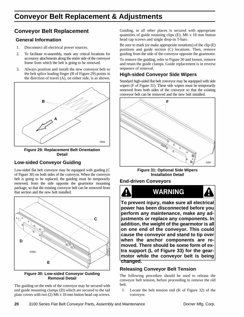
3. Always position and install the new conveyor belt sothe belt splice leading finger (B of Figure 29) points inthe direction of travel (A), on either side, is as shown.
Figure 29: Replacement Belt OrientationDetail
0064
B
A
Low-sided Conveyor Guiding
Low-sided flat belt conveyor may be equipped with guiding (Cof Figure 30) on both sides of the conveyor. When the conveyorbelt is going to be replaced, the guiding must be temporarilyremoved, from the side opposite the gearmotor mountingpackage, so that the existing conveyor belt can be removed fromthat section and the new belt installed.
Figure 30: Low-sided Conveyor GuidingRemoval Detail
C
E
0286c
D
The guiding on the ends of the conveyor may be secured withend guide mounting clamps (D) which are secured to the tailplate covers with two (2) M6 x 18 mm button head cap screws.
Guiding, in all other places is secured with appropriatequantities of guide retaining clips (E), M6 x 18 mm buttonhead cap screws and single drop-in T-bars.
Be sure to mark (or make appropriate notations) of the clip (E)positions and guide section (C) locations. Then, removeguiding from the side of the conveyor opposite the gearmotor.
To remove the guiding, refer to Figure 30 and loosen, removeand retain the guide clamps. Guide replacement is in reversesequence of removal.
High-sided Conveyor Side WipersStandard high-sided flat belt conveyor may be equipped with sidewipers (F of Figure 31). These side wipers must be temporarilyremoved from both sides of the conveyor so that the existingconveyor belt can be removed and the new belt installed.
Figure 31: Optional Side WipersInstallation Detail
0397
F
End-driven Conveyors
To prevent injury, make sure all electricalpower has been disconnected before youperform any maintenance, make any ad-justments or replace any components. Inaddition, the weight of the gearmotor is allon one end of the conveyor. This couldcause the conveyor and stand to tip overwhen the anchor components are re-moved. There should be some form of ex-tra support (L of Figure 33) for the gear-motor while the conveyor belt is beingchanged.
Ç ÇÇ
Releasing Conveyor Belt Tension The following procedure should be used to release theconveyor belt tension, before proceeding to remove the oldbelt.
1. Locate the belt tension end (K of Figure 32) of theconveyor.
Conveyor Belt Replacement & Adjustments

Dorner Mfg. Corp. 3100 Series Flat Belt Conveyor Parts, Assembly and Maintenance 21
2. On a standard high-sided conveyor only, removeeach filler plate screw (H) and each filler plate (G) fromboth sides of the conveyor.
3. If engaged, loosen the belt tracking cam assemblies (I),on both sides of the tensioning end (J). Slide the camassemblies toward the middle of the conveyor.
4. Loosen the tail cover plate screws (L), on both sides ofthe tensioning end.
5. Collapse the tensioning end (J) of the conveyor bypushing it back into the conveyor frame, using the heelof your hand. This will sufficiently loosen the belt forremoval.
0399
Figure 32
K
LJ
G
H
I
Belt Removal
1. Wherever possible, conveyor belt should always beremoved from the side opposite the gearmotor, Inaddition, remove any controls, stops or other attachedaccessories, from that side, which could interfere withbelt removal.
2. Referring to Figure 33, safely and temporarily supportthe conveyor section with a sturdy support mechanism(L) (such as wooden blocks or a sawhorse).
NOTE:For additional details, refer your Metric Support Standsand Conveyor Mountings Parts, Assembly & Mainte-nance Manual.
3. Remove and retain the mounting clamp plate screw (Nof Figure 33) and clamp plate (M) from the both sidesof the conveyor.
4. With the clamp plates (M) removed from both sides ofthe conveyor, carefully raise-up the side opposite thegearmotor and slide the old belt sideways and away fromconveyor.
5. As necessary, remove the old conveyor belt, section bysection, until it is completely off.
Figure 33
L
M
0299b
N
Belt Replacement 1. Install the new conveyor belt by raising the side
opposite the gearmotor and sliding belt sidewaysbetween the bottom of conveyor and the top of themounting bracket return belt roller.
2. As necessary, install the new conveyor belt, section bysection, until it is completely in position around conveyor.
3. Then, replace and re-secure the clamp plates (M) andmounting clamp plate screws (N).
NOTE:On low-side conveyors, do not replace the guiding, atthis time. Replace the guiding after proper conveyor belttension has been achieved.
4. Make sure all hardware, that was either removed orloosened, is replaced and properly tightened. Do not,tightly secure the tail cover plate screws, at this time.
5. Refer to procedures under the “End Driven Conveyors”subtopic in the “Start-up & Preliminary Adjustments”section on page 12 for conveyor belt tension adjustmentprocedures.
Conveyor Belt Replacement & Adjustments

22 3100 Series Flat Belt Conveyor Parts, Assembly and Maintenance Dorner Mfg. Corp.
6. Refer to the “Conveyor Belt Tracking” information inthe Start-up & Preliminary Adjustments section onpage 13 for belt tracking procedures.
7. On low-side conveyors, replace the guiding.
8. After the proper belt tension and tracking is established,replace the controls, stops and other attached accessoriesreferring to the positions previously marked.
Center-driven Conveyors
Preferred Method of Conveyor BeltRemoval & Replacement
NOTE:The preferred method for conveyor belt replacement isto order a replacement belt already cut to length withsplicing fingers pre-cut on each end. The new belt canthen be fused on location with a Belt Splicer either pur-chased or rented from an authorized Dorner ServiceCenter or the factory.
The following belt replacement procedure is preferred forlong conveyors and/or those used in systems with complexmounted controls, guides and accessories.
To prevent injury, make sure all electricaland pneumatic power sources have beendisconnected and locked-out before youperform any maintenance, make anyadjustments or replace any components.
Ç ÇÇ
1. Disconnect all pneumatic and electrical power sources.
2. Remove air pressure from the take-up air cylinder (A ofFigures 34 & 35).
3. To facilitate re-assembly, mark critical locations onconveyor frame and remove guiding, controls, stopsand other attached accessories which will interfere withbelt removal.
4. Open the horizontal Poly-V belt drive cover (B ofFigure 34) or the vertical timing belt drive cover (B ofFigure 35) and release drive belt tension. Then, removethe drive belt so the drive pulleys rotate freely.
5. Cut the old belt perpendicularly to the conveyor center-line.
6. Tape (D) one end of the new belt (C) to one end of theold belt (E).
Figure 34
C ED
A B
Figure 35
C ED
A
B
Conveyor Belt Replacement & Adjustments

Dorner Mfg. Corp. 3100 Series Flat Belt Conveyor Parts, Assembly and Maintenance 23
7. Rotate the old belt in the direction shown to pull the newbelt into the conveyor while pulling the old belt out.
8. New belts without splice fingers are to be cut using aDorner belt cutting tool following instructions pro-vided with the cutting tool.
9. Fuse the new belt in place with a Dorner 7000 Seriesauto belt splicer following instructions provided withthe belt splicer.
NOTE:It may be necessary to remove a tail section to allowenough belt slack for splicing. Appropriate operatinginstructions are contained in the 7000 Series FingerSplice Cutter publication (Dorner 851-103) or in the7000 Series Auto Cycle Belt Splicer publication (Dorner851-102).
NOTE:A Metal hook/Clipper splice may be used in place of afused splice. For this type of conveyor belt, it is only nec-essary to remove the lacing pin to uncouple the two endsof the belt. Then, after the belt is pulled into and throughthe center drive and around the conveyor (using the oldbelt), the ends can be brought together and linked by thelacing pin.
10. Replace and re-secure tail section (if removed) andtightly secure the tail cover plate screws.
11. Replace and re-tension the drive belt. Then, replace thedrive cover.
12. Install the belt tracking guide assemblies on thedischarge end of low side conveyors longer than 14 ft(4.5 m). Refer to Figure 3 on page 5.
13. Make sure the conveyor belt tension is set properly. Referto “Center-drive Conveyors” subtopic under the “Con-veyor Belt Tension Adjustment” topic on page 13.
14. Replace any other items that were removed for the beltreplacement.
15. Make tracking adjustments as needed. Refer to “Con-veyor Belt Tracking” topic on page 13.
Alternate Method for Re-threading Conveyor BeltThrough Center Drive Module
The following belt replacement procedure should be used forinstalling a replacement conveyor belt, with splice fingers,through the center drive module, without dropping the module.
All Center Drive Conveyors
To prevent injury, make sure all electricaland pneumatic power sources have beendisconnected and locked-out before youperform any maintenance, make anyadjustments or replace any components.
ÇÇ Ç
1. Disconnect all pneumatic and electrical power sources.
2. Remove air pressure from the take-up air cylinder (F ofFigures 36 & 37).
3. To facilitate re-assembly, mark critical locations onconveyor frame and remove guiding, controls, stopsand other attached accessories which will interfere withbelt removal.
4. On one end of the conveyor, remove a tail section byloosening the tail cover plate screws and sliding the tailout from the conveyor.
C
GI
F
N
Figure 36
M
Conveyor Belt Replacement & Adjustments

24 3100 Series Flat Belt Conveyor Parts, Assembly and Maintenance Dorner Mfg. Corp.
Belt Installation on Horizontal Center Drive ConveyorsOnly (Alternate Method)
5. Open the horizontal Poly-V belt drive cover (B ofFigure 34) and release drive belt tension. Then, removethe drive belt so the drive pulleys rotate freely.
6. Refer to Figure 36 and remove both take-up pulleys (Gof Figure 36).
7. Remove the two take-up guides (I) from one side.Remove the inner and outer take-up plate assembliesand slide out both pulleys and shafts.
8. Remove the fixed position idler pulley (M). Removethe shaft retaining clip from one side and push out theshaft. Then, remove the pulley.
9. Remove the lower drive pulley (N) from the drivepulley shaft. Remove the drive bearing assembly, fromone side. Then, pull the drive pulley out of the centerdrive unit.
10. With the pulleys and shafts (G, M and N) removed, thesplice fingers of the correctly oriented replacementconveyor belt can be brought into the center drivemodule and routed around the two remaining pulleys asshown in Figure 36.
NOTE:Make sure that the replacement belt is proper orientedwith respect to the direction of travel. Refer to Figure 29on page 20. All horizontal center-driven conveyor beltstravel in the direction indicated by the arrow (C of Figure36).
11. Form a large loop with the conveyor belt inside themodule and re-install the lower drive pulley (N), drivepulley shaft and the drive bearing assembly. Make sureall three elements are correctly positioned beforetightly securing the bearing hardware.
12. On the appropriate side of the belt loop, replace the fixedposition idler pulley (M) and pulley shaft. Re-secure theshaft by re-attaching the shaft retaining clip.
13. Replace both take-up pulleys (G) and the inner andouter take-up plate assemblies. Then, replace the twotake-up guides (I). Again, make sure all elements arecorrectly aligned before tightly securing the take-upbar attaching hardware.
14. After the conveyor belt has been properly replaced andre-routed through the center drive module, replace thehorizontal Poly-V belt drive, restore drive belt tensionand replace the drive belt cover (B of Figure 34).
15. Complete the splicing process by skipping to step 1, onthe next page.
Belt Installation on Vertical Center Drive ConveyorsOnly (Alternate Method)
1. Open the vertical timing belt drive cover (B of Figure35) and release timing belt tension (L of Figure 37).
Then, remove the timing belt so the drive pulleys rotatefreely.
2. Remove the take-up covers.
Figure 37
0338
F
GH
I
C
J
K
L
3. Remove the take-up pulley (G).
4. Loosen (but do not remove) the take-up bearing lockingcollars, on both ends of the take-up pulley.
5. Loosen the take-up bar (H) from the bearing on one sideand remove the take-up guides (I) from that same side.
6. Pull the take-up bearings and pulley out of the drive.
7. Next, remove the center idler pulley (J) by removingthe end plate from both ends of the pulley shaft andpush the shaft out from the drive. Then, remove theidler pulley.
8. With the pulleys and shafts (G and J) removed, thesplice fingers of the correctly oriented replacementconveyor belt can be brought into the center drivemodule and routed around the three remaining pulleysas shown in Figure 37.
NOTE:Make sure that the replacement belt is proper orientedwith respect to the direction of travel. Refer to Figure 29on page 20. All horizontal center-driven conveyor beltstravel in the direction indicated by the arrow (C of Figure36).
9. Form a large loop, with the conveyor belt, inside themodule and re-install the center idler pulley (J) on theappropriate side of the belt loop. In conjunction withthe pulley, re-assemble the end plates and the pulleyshaft. Make sure all three elements are correctlypositioned before tightly securing the shaft retainingclip hardware.
Conveyor Belt Replacement & Adjustments

Dorner Mfg. Corp. 3100 Series Flat Belt Conveyor Parts, Assembly and Maintenance 25
10. Replace the take-up guides (I). Then, replace, align andsecure the take-up bar (H).
11. On the appropriate side of the belt loop, replace thetake-up pulley (G) and the take-up bearing lockingcollars, on both ends of the take-up pulley. Again, makesure all elements are correctly aligned before tightlysecuring the bearing locking collars.
12. After the conveyor belt has been properly replaced andre-routed through the center drive module, replace thetiming belt, restore timing belt tension and replace thedrive belt cover (B of Figure 35).
Belt Fusing and System Restoration 1. Fuse the new belt in place with a Dorner 7000 Series
auto belt splicer following instructions provided withthe belt splicer.
NOTE:It may be necessary to remove a tail section to allowenough belt slack for splicing. Appropriate operatinginstructions are contained in the 7000 Series FingerSplice Cutter publication (Dorner 851-103) or in the7000 Series Auto Cycle Belt Splicer publication (Dorner851-102).
2. Install the belt tracking guide assemblies on thedischarge end of low side conveyors longer than 14 ft(4.5 m). Refer to Figure 3 on page 5.
3. Make sure the conveyor belt tension is set properly. Referto “Center-drive Conveyors” subtopic under the “Con-veyor Belt Tension Adjustment” topic on page 13.
4. Replace any other items that were removed for the beltreplacement.
5. Make tracking adjustments as needed. Refer to “Con-veyor Belt Tracking” topic on page 13.
Conveyor Belt Replacement & Adjustments

26 3100 Series Flat Belt Conveyor Parts, Assembly and Maintenance Dorner Mfg. Corp.
BearingsProblem Possible Cause Solution
Bearing failing orseizing [tail sectionwith 1″ (25 mm)
Grit getting into bearing. Bearing not beingproperly lubricated.
Maintain regular lubrication routine. Sidewipers may be needed along with increasedfrequency of lubrication.
Pulleys Only]
Note: All other
Solvent getting into bearings. Same as above. Keep grease fittings inretaining sleeves. Install guards and tiltconveyor to reduce amount of solvent onconveyor.
bearings have beenlubricated for life and
Excessive heat in application. Increase frequency of lubrication.lubricated for life andsealed. Damage due to improper re-assembly. Use tool kit for proper re-assembly.
Gearmotor
Remove power before attempting to re-wiremotor or system electrical control.
Ç Ç
Problem Possible Cause Solution
Motor cuts outintermittently.
Overloading. Check conveyor load. Use torque wrench todetermine input torque. Check for guides oraccessories rubbing on belt. Check belttracking.
Improper cooling. Check motor operation and ambienttemperature.
Motor running hot.[above 170°F (77°C)].
Overloading. Check ampere draw, replace motor, reduceconveyor load.
Jammed part. Remove jam.
Note: 1/3 hp Baldornormally runs at170°F (77°C).
Incorrect voltage/wiring. Check wiring diagram. Replace motor orchange wiring.
Improper cooling. Reduce excessive ambient temperature.
Conveyor runs inwrong direction.
Improper wiring. Check wiring diagram.
Oil leaking fromgearbox.
Broken seal. Contact manufacturer for replacement parts orDorner for further information. Contact Dornerfor new gearbox.
Oil vent plug installed below oil level. Reinstall vent plug well above oil level.
Oil level too high. See instructions for gearbox oil capacity.
Failure to install vent plug. Contact Dorner to locate a manufacturer’sservice representative or to order a new gearreducer.
Gear Reducer
Problem Possible Cause Solution
Oil/grease leakingfrom gearbox.
Broken seal. Contact manufacturer for replacement parts orDorner for ordering new gear reducer.
Oil vent plug installed below oil level. Re-locate plug above oil level.
Troubleshooting Guide

Dorner Mfg. Corp. 3100 Series Flat Belt Conveyor Parts, Assembly and Maintenance 27
Problem SolutionPossible CauseOil level too high. See manufacturer’s oil amount
recommendation.
Vent plug not installed. Contact manufacturer for replacement parts orDorner for ordering new gear reducer.

28 3100 Series Flat Belt Conveyor Parts, Assembly and Maintenance Dorner Mfg. Corp.
Vertical Center Drive Timing Belt
Problem Possible Cause SolutionIntermittent conveyorbelt travel.
Timing belt is too loose. Adjust belt tension. Refer to “Timing BeltTension Adjustment” beginning on page 8.
Worn or damaged timing (drive) belt. Replace defective timing belt.
Conveyor Belt
Problem Possible Cause SolutionBelt slipping. Belt is too loose. Adjust belt tension. If belt is still loose, replace
belt. Note: Belt may have stretched. See“Belt Stretching” problem.
Dirt impacted in knurl on end of driven pulley. Clean pulley.
Knurl worn on driven pulley. Replace pulley.
Excessive weight on conveyor. Note: May bea combination of drive “pushing” belt ormagnets too strong for application.
Reduce weight on conveyor by reducingproduction rate, or increasing belt speed.
Drive is “pushing” belt. Note: May be acombination of this and excessive weighton conveyor.
Move end drive to discharge end of conveyor.Turn center drive 180° so gearmotor and drivenpulley are towards discharge end.
Magnets, where provided, are too strong forapplication.
Increase belt speed or replace magneticbedplate.
Debris wedged in belt path or in conveyor. Clean conveyor and install chute and/or wipers.
Belt stretching. Solvent or chemical reaction with belt. Remove solvent or try a different belt material.Test solvent with belt sample. Note: Belt typeconveyor may not be applicable.
Belt repeatedly stalled, causing pulley to wearor “burn” in to backside of belt.
Replace belt and identify reason for stalling.
Cuts on belt surface. Side wipers damaged or missing, allowingmaterial to get under belt.
Replace or add wipers as needed.
Sharp parts penetrating belt surface. Install baffle to reduce energy of falling part.
Guides or accessories rubbing on belt. Adjust as necessary.
Worn belt edges. Debris impacted on pulleys can cause belttracking problems.
Clean pulleys. Correct source of contamination.See Belt Tracking Incorrectly below.
Belt tracking incorrectly. Refer to “Belt Tracking Adjustment”, page 13.
Belt breaking atsplice.
Solvent or chemical reaction with belt. Remove solvent or try a different belt material.Test solvent with belt sample. Note: Belt typeconveyor may not be applicable.
Belt tracking incorrect-ly.
Drives not perpendicular to conveyor centerline.
Reposition drive(s), if necessary.
Frame misalignment. Note: Frame mountingsurface maybe misaligned.
Frame mounting must be straight and in thesame plane. Check with a straight edge andlevel.
Frame distortion due to damage. Repair or replace frame components and/orbed plate. Check with a straight edge.
Side force being applied to belt. Check for jammed part or mechanical pusherforce on belt.
Belt tracking cam incorrectly adjusted. Refer to “Belt Tracking Adjustment”, page 13.
Hot spots on frame or drive side plates from beltedge rubbing.
Adjust belt tracking. Refer to “Belt TrackingAdjustment”, page 13.
TroubleshootingGuide

Tool Kit3100 Series Flat Belt Conveyors
Dorner Mfg. Corp. 3100 Series Flat Belt Conveyor Parts, Assembly and Maintenance 29
0154
StorageSpace forHex KeysItems 1
through 6,10, & 27
through 30
7 8
9
22
23
24
25
26
17
18
19
20
21
Container withMiscellaneous
Parts Items 11 - 16
Tool Kit - Part Number 2500M-ENG
Item Part No. Description Qty.
1 807-562 Hex Key, 2.5 mm Long Arm 2 2 807-563 Hex Key, 3 mm Long Arm 2 3 807-564 Hex Key, 4 mm Long Arm 2 4 807-565 Hex Key, 5 mm Long Arm 2 5 807-566 Hex Key, 6 mm Long Arm 1 6 807-568 Hex Key, 8 mm Long Arm 1 7 807-610 Hex Key, 3 mm T-Handle 1 8 807-609 Hex Key, 4 mm T-Handle 1 9 807-569 Hex Key, 5 mm T-Handle 110 807-577 Torx� Key T-25 Short Arm 111 200039M Belt Tracking Cam 212 300353MP Special Flat Head Cap Screw,
M4-0.70 x 10 mm8
13 910506M Button Head Cap Screw,M5-0.80 x 6 mm
4
14 910510M Button Head Cap Screw,M5-0.80 x 10 mm
4
15 910612M Button Head Cap Screw,M6-.1.0 x 12 mm
4
Item Part No. Description Qty.
16 920406M Socket Head Cap Screw,M4-0.70 x 6 mm
6
17 200046M Greasing Adapter 118
25-09Retaining Sleeve/Bearing RemovalTool
1
19 920635M Socket Head Cap Screw,M6-1.0 x 35 mm
1
20 605279 Washer, Special 121 906-278 Bolt, Special Threaded 122 25-10 Bearing Insertion Tool 123 25-08 Hex Key Extension Tool
2″ (44 mm) to 12″ (610 mm)1
24 25-05 Bearing Removal Tool 125 300362M Tail Installation Tool 2
26 661451 Tool Box 2500M-ENG 127 807-518 Hex Key, 1/8″ Long Arm 128 807-520 Hex Key, 3/16″ Long Arm 129 807-528 Hex Key, 7/32″ Long Arm 130 807-521 Hex Key, 1/4″ Long Arm 1

Replacement Parts 3100 Series Flat Belt Conveyors
30 3100 Series Flat Belt Conveyor Parts, Assembly and Maintenance Dorner Mfg. Corp.
Conveyor Belt Part Number
DD– WWLL/ BB
Belt Type: See below.
Nominal Conveyor Length in feet.
Nominal Belt Width in inches.
End Drive = 30
Vertical Center Drive = 31
Standard Load Horizontal Center Drive = 32
Heavy Load Horizontal Center Drive = 33
Conveyor Type:
Belt Type - BB/01 Accumulator Top FDA Approved 80-90 Durometer
surface hardness. Products may be accumulated onthe low friction surface of this belt. Maximum parttemperature is 176 °F (80 °C). Smooth, thermallywelded zig-zag splice*. Belt thickness about 0.063″(1.6 mm).
/02 Standard Urethane 75-85 Durometer surfacehardness. This is our standard belting, very durableand works well in most applications. Maximum parttemperature is 212 °F (100 °C). Smooth, thermallywelded zig-zag splice*. Belt thickness about 0.071″(1.8 mm).
/03 Soft Urethane FDA Approved 70-80 Durometersurface hardness. This belt provides more surfacefriction and is more resistant to chemicals than /01 or/02. Maximum part temperature is 176 °F (80 °C).Smooth, thermally welded zig-zag splice*. Beltthickness about 0.063″ (1.6 mm).
/04 Gray Friction Belt This belt provides a high degree ofsurface traction when clean and dry. It can be used toconvey parts up inclines or in other applications whereparts must not slide on the belt surface. This beltshould not be used with very small or sharp parts.Maximum part temperature is 158 °F (70 °C). Smooth,thermally welded zig-zag splice*. Belt thickness about0.083″ (2.1 mm).
NOTE:04 Gray Friction Belt cannot be used with 03 and/or 06Side Profiles.
EXAMPLE: #2 Standard Urethane replacement belt for anend drive conveyor measuring 5″ (127 mm) wide x 8’(2438 mm) long would be Part Number 30-0508/02.
NOTE:All belts include a thermally welded finger splice*. IfClipper spliced belt is required, add a “-C” suffix.
EXAMPLE: Part No 30-0508/02-C
NOTE:For replacement belting on vacuum and speciallymodified conveyors, contact factory with model & ordernumbers for replacement information.
/05 Woven Polyester Belt Offers advantages in lowfriction product accumulation. Maximum parttemperature is 212 °F (100 °C). Smooth, thermallywelded zig-zag splice*. Belt thickness about 0.047″(1.2 mm).
/06 Black Anti-Static Belt Is a carbon impregnatedpolyester belt used where an anti-static/conductivebelt is required. Belt should be tested per applicationfor resistance to ground. Maximum part temperatureis 230 °F (110 °C). Smooth, thermally welded zig-zagsplice*. Belt thickness about 0.063″ (1.6 mm).
/07 Heat Resistant Belt This belt resists producttemperatures up to 358 �F (180 °C). Smooth,thermally bonded zig-zag splice*. Belt thickness about0.051″ (1.3 mm).
* Thermal splice is standard. Clipper� splice is availableupon request.

Replacement Parts3100 Series Flat Belt Conveyors
Dorner Mfg. Corp. 3100 Series Flat Belt Conveyor Parts, Assembly and Maintenance 31
Item Part No. Part Description
1 See Chart Bedplate
2 300353MP Bedplate Screw, M4-0.70 x 10 mm
3 See Chart Rail Nut Strip
4 See Chart Center Rail
5 910516M Button Head Cap Screw, M5-0.80 x 16 mm
6 930525M Flat Head Cap Screw, M5-0.80 x 25 mm
7 910525M Button Head Cap Screw, M5-0.80 x 25 mm
8 See Chart Side Rail, Non-tension End, Low Side
9 See Chart Side Rail, Non-tension End, High Side
10 See Chart Center Rail, Tension End
11 307201 Spacer, Nut Strip (see page 32)
NOTE: Metric parts listed. For SAE parts, other than fasteners, drop the “M” suffix. SAE equivalent fasteners are identified in the table on page
73.
Conveyors with High Sides
3
2
10
1
5
6 7 8
9
Intermediate Sections
2
2
3
3
4
4
5
5
5
5
5
6
6
6
7
8
0316
ConveyorswithLow Sides

Replacement Parts 3100 Series Flat Belt Conveyors
32 3100 Series Flat Belt Conveyor Parts, Assembly and Maintenance Dorner Mfg. Corp.
NOTE: Intermediate sections are available in standard nominal lengths and widths as shown below. The 18″ (457 mm) bedplateuses a combination of a 10″ (254 mm) and an 8″ (203 mm) bedplate (laid side by side), the 24″ (610 mm) bedplate uses acombination of two 12″ (305 mm) bedplates (laid side by side), the 30″ (762 mm) bedplate uses a combination of three 10″ (254mm) bedplates (laid side by side), the 36″ (915 mm) bedplate uses a combination of three 12″ (305 mm) bedplates (laid side byside) and, the 40″ (1016 mm) bedplate uses a combination of four 10″ (254 mm) bedplates (laid side by side). Each pair of nut strips,used to secure the bedplates, are separated by a nut strip spacer (11).
3012LLBedplate
307212Nut Strip
307212Nut Strip
3012LLBedplate
11
24″(610 mm)
3012LLBedplate
3012LLBedplate
3012LLBedplate
307212Nut Strip
307212Nut Strip
307212Nut Strip 1111
3010LLBedplate
3010LLBedplate
3010LLBedplate
3010LLBedplate
307210Nut Strip
307210Nut Strip
307210Nut Strip
307210Nut Strip 11 1111
36″(915 mm)
40″(1016 mm)
3010LLBedplate
3008LLBedplate
307210Nut Strip
307208Nut Strip11
18″(457 mm)
3010LLBedplate
3010LLBedplate
3010LLBedplate
307210Nut Strip
307210Nut Strip
307210Nut Strip 11 11
30″(762 mm)
Bedplate Item 1
Length in ft (mm)
Width in″ (mm) 2 (610) 3 (915) 4 (1220) 5 (1525) 6 (1830) 7 (2135) 8 (2440) 9 (2745) 10 (2050) 11 (3355) 12 (3660)4 (95) 300402P 300403P 300404P 300405P 300406P 300407P 300408P 300409P 300410P 300411P 300412P
5 (127) 300502P 300503P 300504P 300505P 300506P 300507P 300508P 300509P 300510P 300511P 300512P6 (152) 300602P 300603P 300604P 300605P 300606P 300607P 300608P 300609P 300610P 300611P 300612P8 (203) 300802P 300803P 300804P 300805P 300806P 300807P 300808P 300809P 300810P 300811P 300812P10 (254) 301002P 301003P 301004P 301005P 301006P 301007P 301008P 301009P 301010P 301011P 301012P12 (305) 301202P 301203P 301204P 301205P 301206P 301207P 301208P 301209P 301210P 301211P 301212P
18 (457)300802P
& 301002P300803P
&301003P300804P
& 301004P300805P
& 301005P300806P
& 301006P300807P
& 301007P300808P
& 301008P300809P
& 301009P300810P
& 301010P300811P
&301011P300812P
&301012P
24 (610)301202P
& 301202P301203P
&301203P301204P
& 301204P301205P
& 301205P301206P
& 301206P301207P
& 301207P301208P
& 301208P301209P
&301209P301210P
&301210P301211P
& 301211P301212P
&301212P
36 (915) 301202P(Qty. 3)
301203P(Qty. 3)
301204P(Qty. 3)
301205P(Qty. 3)
301206P(Qty. 3)
301207P(Qty. 3)
301208P(Qty. 3)
301209P(Qty. 3)
301210P(Qty. 3)
301211P(Qty. 3)
301212P(Qty. 3)
40 (1016) 301002P(Qty. 4)
301003P(Qty. 4)
301004P(Qty. 4)
301005P(Qty. 4)
301006P(Qty. 4)
301007P(Qty. 4)
301008P(Qty. 4)
301009P(Qty. 4)
301010P(Qty. 4)
301011P(Qty. 4)
301012P(Qty. 4)
Rail Nut StripItem 3
Width Part No.4″ (95 mm) 307204M
5″ (127 mm) 307205M
6″ (152 mm) 307206M
8″ (203 mm) 307208M
10″ (203 mm) 307210M
12″ (305 mm) 307212M
18″ (457 mm) 307208 M &307210M
24″ (610 mm) 307212M (2x)
30″ (762 mm) 307210M (3x)
36″ (915 mm) 307212M (3x)
40″ (1016 mm) 307210M (4x)
Center RailItem 4
Width Part No.4″ (95 mm) 300204M
5″ (127 mm) 300205M
6″ (152 mm) 300206M
8″ (203 mm) 300208M
10″ (254 mm) 300210M
12″ (305 mm) 300212M
18″ (457 mm) 300218M
24″ (610 mm) 300224M
30″ (762 mm) 300230M
36″ (915 mm) 300236M
40″ (1016 mm) 300240M
Side RailItems 8 and 9
Length inft (mm)
LowSide
HighSide
2 (610) 303502 3036023 (915) 303503 303603
4 (1220) 303504 3036045 (1525) 303505 3036056 (1830) 303506 3036067 (2135) 303507 3036078 (2440) 303508 3036089 (2745) 303509 30360910 (2050) 303510 30361011 (3355) 303511 30361112 (3660) 303512 303612
Center Rail, TensionEnd Item 10
Width Part No.4″ (95 mm) 303304M
5″ (127 mm) 303305M
6″ (152 mm) 303306M
8″ (203 mm) 303308M
10″ (254 mm) 303310M
12″ (305 mm) 303312M
18″ (457 mm) 303318M
24″ (610 mm) 303324M
30″ (762 mm) 303330M
36″ (915 mm) 303336M
40″ (1016 mm) 303340M

Replacement Parts3100 Series Flat Belt Conveyors
Dorner Mfg. Corp. 3100 Series Flat Belt Conveyor Parts, Assembly and Maintenance 33
NOTE: Metric parts listed. For SAE parts, other than fasteners, drop the “M” suffix. SAE equivalent fasteners are identified in the table on page
73.

Replacement Parts 3100 Series Flat Belt Conveyors
34 3100 Series Flat Belt Conveyor Parts, Assembly and Maintenance Dorner Mfg. Corp.
Tail Bed Plate for 18 to 40″(457 & 1016 mm) widths
Fixed End Tail Assembly – 3″ (76 mm) Pulley
1
2 3
4
5
111213
14
17
18
20
21
19
16
22
26
24
2523
18
20
10
14
19
16
10
10
13
12 1110
8
8
Tail Plate forHigh Side Conveyors
15
6
3
7
15Tail Plates forLow SideConveyors

Replacement Parts3100 Series Flat Belt Conveyors
Dorner Mfg. Corp. 3100 Series Flat Belt Conveyor Parts, Assembly and Maintenance 35
Item Part No. Part Description 1 300158M Threaded Bushing
2 807-384 Spring Washer
3 301304 Tail Bedplate, Non-tension End, 4″ (95 mm)
301305 Tail Bedplate, Non-tension End, 5″ (127 mm)
301306 Tail Bedplate, Non-tension End, 6″ (152 mm)
301308 Tail Bedplate, Non-tension End, 8″ (203 mm)
301310 Tail Bedplate, Non-tension End, 10″ (254 mm)
301312 Tail Bedplate, Non-tension End, 12″ (305 mm)
301318M Tail Bedplate, Non-tension End, 18″ (457 mm)
301324M Tail Bedplate, Non-tension End, 24″ (610 mm)
301330M Tail Bedplate, Non-tension End, 30″ (762 mm)
301336M Tail Bedplate, Non-tension End, 36″ (915 mm)
301340M Tail Bedplate, Non-tension End, 40″ (1016mm)
4 300155M Bed-Link Mounting Block
5 920650M Socket Head Cap Screw, M6-1.0 x 50 mm
6 930512M Flat Head Cap Screw, M5-0.80 x 12 mm
7 303018M Bedplate Tail Bar, 18″ (457 mm)
303024M Bedplate Tail Bar, 24″ (610 mm)
303030M Bedplate Tail Bar, 30″ (762 mm)
303036M Bedplate Tail Bar, Tension End, 36″ (915 mm)
303040M Bedplate Tail Bar, Tension End, 40″ (1016mm)
8 200331M Cam Mounting Ass’y
10 910612M Button Head Cap Screw, M6-1.0 x 12 mm
11 200038M Cam Clamping Plate
12 200341M Cam Retaining Block
13 200039M Belt Tracking Cam
14 300150M Drop-In T-bar
15 300152M T-bar
16 910506M Button Head Cap Screw, M5-0.80 x 6 mm
17 300028M Tail Cover Plate, Right Hand, 3″ (76 mm)
18 300052M Tail Plate, Right Hand (Low Side),3″ (76 mm)
300050M Tail Plate, Right Hand (High Side),3″ (76 mm)
19 930612M Flat Head Cap Screw, M6-1.0 x 12 mm
20 300053M Tail Plate, Left Hand (Low Side), 3″ (76 mm)
300051M Tail Plate, Left Hand (High Side), 3″ (76 mm)
21 300029M Tail Cover Plate, Left Hand, 3″ (76 mm)
Item Part No. Part Description22 326704 Idler Pulley Ass’y 4″ (95 mm)
326705 Idler Pulley Ass’y 5″ (127 mm)
326706 Idler Pulley Ass’y 6″ (152 mm)
326708 Idler Pulley Ass’y 8″ (203 mm)
326710 Idler Pulley Ass’y 10″ (254 mm)
326712 Idler Pulley Ass’y 12″ (305 mm)
326718 Idler Pulley Ass’y 18″ (457 mm)
326724 Idler Pulley Ass’y 24″ (610 mm)
326730 Idler Pulley Ass’y 30″ (762 mm)
326736 Idler Pulley Ass’y 36″ (915 mm)
326740 Idler Pulley Ass’y 40″ (1016 mm)
23 326604 Aluminum Pulley Tube, 4″ (95 mm)
326605 Aluminum Pulley Tube, 5″ (127 mm)
326606 Aluminum Pulley Tube, 6″ (152 mm)
326608 Aluminum Pulley Tube, 8″ (203 mm)
326610 Aluminum Pulley Tube, 10″ (254 mm)
326612 Aluminum Pulley Tube, 12″ (305 mm)
326618 Aluminum Pulley Tube, 18″ (457 mm)
326624 Aluminum Pulley Tube, 24″ (610 mm)
326630 Aluminum Pulley Tube, 30″ (762 mm)
326636 Aluminum Pulley Tube, 36″ (915 mm)
326640 Aluminum Pulley Tube, 40″ (1016 mm)
24 802-110 Ball Bearing (Set Screws Removed)
25 915-051 Retaining Ring
26 301904 Idler Shaft 4″ (95 mm) Wide
301905 Idler Shaft 5″ (127 mm) Wide
301906 Idler Shaft 6″ (152 mm) Wide
301908 Idler Shaft 8″ (203 mm) Wide
301910 Idler Shaft 10″ (254 mm) Wide
301912 Idler Shaft 12″ (305 mm) Wide
301918 Idler Shaft 18″ (457 mm) Wide
301924 Idler Shaft 24″ (610 mm) Wide
301930 Idler Shaft 30″ (762 mm) Wide
301936 Idler Shaft 36″ (915 mm) Wide
301940 Idler Shaft 40″ (1016 mm) Wide
NOTE: Metric parts listed. For SAE parts, other than fasteners, drop the “M” suffix. SAE equivalent fasteners are identified in the table on page
73.

Replacement Parts 3100 Series Flat Belt Conveyors
36 3100 Series Flat Belt Conveyor Parts, Assembly and Maintenance Dorner Mfg. Corp.
Tail Bed Platefor 18 to 40″(457 & 1016 mm) widths
Fixed End Tail Assembly 1″ (25 mm) Pulleys
Tail Plate forHigh SideConveyors
1
2
3
4
5
111213
14
1517
18
20
21
19
16
2324
25
27
20
10
1419
16
10
10
13
12 11 10
8
8
28
15
6
7
3
22
23 24
22
26
2618
Tail Plates forLow SideConveyors

Replacement Parts3100 Series Flat Belt Conveyors
Dorner Mfg. Corp. 3100 Series Flat Belt Conveyor Parts, Assembly and Maintenance 37
Item Part No. Part Description 1 300158M Threaded Bushing
2 807-384 Spring Washer
3 301304 Tail Bedplate, Non-tension End, 4″ (95 mm)
301305 Tail Bedplate, Non-tension End, 5″ (127 mm)
301306 Tail Bedplate, Non-tension End, 6″ (152 mm)
301308 Tail Bedplate, Non-tension End, 8″ (203 mm)
301310 Tail Bedplate, Non-tension End, 10″ (254 mm)
301312 Tail Bedplate, Non-tension End, 12″ (305 mm)
301318M Tail Bedplate, Non-tension End, 18″ (457 mm)
301324M Tail Bedplate, Non-tension End, 24″ (610 mm)
4 300155M Bed-Link Mounting Block
5 920650M Socket Head Cap Screw, M6-1.0 x 50 mm
6 930512M Flat Head Cap Screw, M5-0.80 x 12 mm
7 303018M Bedplate Tail Bar, 18″ (457 mm)
303024M Bedplate Tail Bar, 24″ (610 mm)
8 200331M Cam Mounting Ass’y
10 910612M Button Head Cap Screw, M6-1.0 x 12 mm
11 200038M Cam Clamping Plate
12 200341M Cam Retaining Block
13 200039M Belt Tracking Cam
14 300150M Drop-In T-bar
15 300152M T-bar
16 910506M Button Head Cap Screw, M5-0.80 x 6 mm
17 300030M Tail Cover Plate, Right Hand
18 300056M Tail Plate, Right Hand (Low Side)
300054M Tail Plate, Right Hand (High Side)
19 930612M Flat Head Cap Screw, M6-1.0 x 12 mm
20 300057M Tail Plate, Left Hand (Low Side)
300055M Tail Plate, Left Hand (High Side)
21 300031M Tail Cover Plate, Left Hand
Item Part No. Part Description
22 300035M Retaining Sleeve Ass’y
23 300036M Retaining Sleeve
24 810-292 Grease Fitting
25 303104 Pulley Ass’y, 4″ (95 mm)
303105 Pulley Ass’y, 5″ (127 mm)
303106 Pulley Ass’y, 6″ (152 mm)
303108 Pulley Ass’y, 8″ (203 mm)
303110 Pulley Ass’y, 10″ (254 mm)
303112 Pulley Ass’y, 12″ (305 mm)
303118 Pulley Ass’y, 18″ (457 mm)
303124 Pulley Ass’y, 24″ (610 mm)
26 21-33 Bearing
27 302204 Pulley, 4″ (95 mm)
302205 Pulley, 5″ (127 mm)
302206 Pulley, 6″ (152 mm)
302208 Pulley, 8″ (203 mm)
302210 Pulley, 10″ (254 mm)
302212 Pulley, 12″ (305 mm)
302218 Pulley, 18″ (457 mm)
302224 Pulley, 24″ (610 mm)
28 302104 Pulley Shaft, 4″ (95 mm)
302105 Pulley Shaft, 5″ (127 mm)
302106 Pulley Shaft, 6″ (152 mm)
302108 Pulley Shaft, 8″ (203 mm)
302110 Pulley Shaft, 10″ (254 mm)
302112 Pulley Shaft, 12″ (305 mm)
302118 Pulley Shaft, 18″ (457 mm)
302124 Pulley Shaft, 24″ (610 mm)
NOTE: Metric parts listed. For SAE parts, other than fasteners, drop the “M” suffix. SAE equivalent fasteners are identified in the table on page
73.

Replacement Parts 3100 Series Flat Belt Conveyors
38 3100 Series Flat Belt Conveyor Parts, Assembly and Maintenance Dorner Mfg. Corp.
Tail Plates forHigh SideConveyors
1
2 3
4
5
6
3
7
910
11
12
13
14
1516
17
19
20
21
22
23
24
21 22
18
Drive End Tail Assembly
13
14
9
17
2016
9
91011
12
PZ07
Tail Plates forLow SideConveyors
8
8
Tail Bed Plate for18 to 40″ (457 to 1016 mm) widths

Replacement Parts3100 Series Flat Belt Conveyors
Dorner Mfg. Corp. 3100 Series Flat Belt Conveyor Parts, Assembly and Maintenance 39
Item Part No. Part Description
1 300158M Threaded Bushing
2 807-384 Spring Washer
3 301304 Tail Bedplate, Non-tension End,4″ (95 mm)
301305 Tail Bedplate, Non-tension End,5″ (127 mm)
301306 Tail Bedplate, Non-tension End,6″ (152 mm)
301308 Tail Bedplate, Non-tension End,8″ (203 mm)
301310 Tail Bedplate, Non-tension End,10″ (254 mm)
301312 Tail Bedplate, Non-tension End,12″ (305 mm)
301318M Tail Bedplate, Non-tension End,18″ (457 mm)
301324M Tail Bedplate, Non-tension End,24″ (610 mm)
301330M Tail Bedplate, Non-tension End,30″ (762 mm)
301336M Tail Bedplate, Non-tension End,36″ (915 mm)
301340M Tail Bedplate, Non-tension End,40″ (1016 mm)
4 300155M Bed-Link Mounting Block
5 920650M Socket Head Cap Screw, M6-1.0 x 50 mm
6 930512M Flat Head Cap Screw, M5-0.80 x 12 mm
7 303018M Bedplate Tail Bar 18″ (457 mm)
303024M Bedplate Tail Bar 24″ (610 mm)
303030M Bedplate Tail Bar 30″ (762 mm)
303036M Bedplate Tail Bar 36″ (915 mm)
303040M Bedplate Tail Bar 40″ (1016 mm)
8 200331M Cam Mounting Ass’y
Item Part No. Part Description
9 910612M Button Head Cap Screw, M6-1.0 x 12 mm
10 200038M Cam Clamping Plate
11 200341M Cam Retaining Block
12 200039M Belt Tracking Cam
13 300150M Drop-In T-bar
14 300152M T-bar
15 300139M Drive Bearing Shaft Cover
16 910506M Button Head Cap Screw, M5-0.80 x 6 mm
17 930612M Flat Head Cap Screw, M6-1.0 x 12 mm
18 910508M Button Head Cap Screw, M5-0.80 x 8 mm
19 300032M Tail Cover Plate, Right Hand, Drive End
20 300146 Bearing Ass’y
21 300068M Tail Plate, Right Hand (Low Side), DriveEnd
300066M Tail Plate, Right Hand (High Side), DriveEnd
22 300069M Tail Plate, Left Hand (Low Side), Drive End
300067M Tail Plate, Left Hand (High Side), Drive End
23 300033M Tail Cover Plate, Left Hand, Drive End
24 303204M Pulley 4″ (95 mm) (19 mm Shaft)
303205M Pulley 5″ (127 mm) (19 mm Shaft)
303206M Pulley 6″ (152 mm) (19 mm Shaft)
303208M Pulley 8″ (203 mm) (19 mm Shaft)
303210M Pulley 10″ (254 mm) (19 mm Shaft)
303212M Pulley 12″ (305 mm) (19 mm Shaft)
303218M Pulley 18″ (457 mm) (19 mm Shaft)
303224M Pulley 24″ (610 mm) (19 mm Shaft)
303230M Pulley 30″ (762 mm) (19 mm Shaft)
303236M Pulley 36″ (915 mm) (19 mm Shaft)
303240M Pulley 40″ (1016 mm) (19 mm Shaft)
NOTE: Metric parts listed. For SAE parts, other than fasteners, drop the “M” suffix. SAE equivalent fasteners are identified in the table on page
73.

Replacement Parts 3100 Series Flat Belt Conveyors
40 3100 Series Flat Belt Conveyor Parts, Assembly and Maintenance Dorner Mfg. Corp.
Tension End Tail Assembly - 3″ (76 mm) Pulley
1
171819
20
2
3
3
6
7
4
4
5
1718
19 2017
28
23
27
24
25
27
28
17
21
2221
22
8
815
9
10
11
12
13
14
Tail Platesfor High SideConveyors
Rack &PinionAssembly
24
29
25
29
9
26
PZ08
Tail Plates for Low SideConveyors
Tail Bed Plate for18 to 40″ (457 to 1016 mm) widths
16
16 8
30
34
32
3331

Replacement Parts3100 Series Flat Belt Conveyors
Dorner Mfg. Corp. 3100 Series Flat Belt Conveyor Parts, Assembly and Maintenance 41
Item Part No. Part Description 1 300158M Threaded Bushing
2 807-384 Spring Washer
3 301704 Tail Bedplate, Tension End, 4″ (95 mm)
301705 Tail Bedplate, Tension End, 5″ (127 mm)
301706 Tail Bedplate, Tension End, 6″ (152 mm)
301708 Tail Bedplate, Tension End, 8″ (203 mm)
301710 Tail Bedplate, Tension End, 10″ (254 mm)
301712 Tail Bedplate, Tension End, 12″ (305 mm)
301718M Tail Bedplate, Tension End, 18″ (457 mm)
301724M Tail Bedplate, Tension End, 24″ (610 mm)
301730M Tail Bedplate, Tension End, 30″ (762 mm)
301736M Tail Bedplate, Tension End, 36″ (915 mm)
301740M Tail Bedplate, Tension End, 40″ (1016 mm)
4 300155M Bed-Link Mounting Block
5 920650M Socket Head Cap Screw, M6-1.0 x 50 mm
6 930512M Flat Head Cap Screw, M5-0.80 x 12 mm
7 303018M Bedplate Tail Bar, 18″ (457 mm)
303024M Bedplate Tail Bar, 24″ (610 mm)
303030M Bedplate Tail Bar, 30″ (762 mm)
303036M Bedplate Tail Bar, 36″ (915 mm)
303040M Bedplate Tail Bar, 40″ (1016 mm)
8 920508M Socket Head Cap Screw, M5-0.80 x 8 mm
9 300169M Rack and Pinion Housing Ass’y
10 200034 Pinion Wear Ring
11 200151 Back Bowed Spring
12 300166M Take-up Rack Housing
13 300167 Rack Gear
14 300168 Wear Rack Strip
15 203004M Pinion Gear 4″ (95 mm)
203005M Pinion Gear 5″ (127 mm)
203006M Pinion Gear 6″ (152 mm)
203008M Pinion Gear 8″ (203 mm)
203010M Pinion Gear 10″ (254 mm)
203012M Pinion Gear 12″ (305 mm)
203018M Pinion Gear 18″ (457 mm)
203024M Pinion Gear 24″ (610 mm)
307030M Pinion Gear 30″ (762 mm)
307036M Pinion Gear 36″ (915 mm)
307040M Pinion Gear 40″ (1016 mm)
16 200331M Cam Mounting Ass’y
17 910612M Button Head Cap Screw, M6-1.0 x 12 mm
18 200038M Cam Clamping Plate
19 200341M Cam Retaining Block
20 200039M Belt Tracking Cam
21 300150M Drop-In T-bar
22 300152M T-bar
23 300028M Tail Cover Plate, Right Hand, 3″ (76 mm)
Item Part No. Part Description24 300060M Tail Plate, Right Hand (Low Side), 3″ (76 mm)
300058M Tail Plate, Right Hand (High Side), 3″ (76 mm)
25 300061M Tail Plate, Left Hand (Low Side), 3″ (76 mm)
300059M Tail Plate, Left Hand (High Side), 3″ (76 mm)
26 300029M Tail Cover Plate, Left Hand, 3″ (76 mm)
27 930612M Flat Head Cap Screw, M6-1.0 x 12 mm
28 910506M Button Head Cap Screw, M5-0.80 x 6 mm
29 300164M Filler Plate (High Side)
30 326704 Idler Pulley Ass’y 4″ (95 mm)
326705 Idler Pulley Ass’y 5″ (127 mm)
326706 Idler Pulley Ass’y 6″ (152 mm)
326708 Idler Pulley Ass’y 8″ (203 mm)
326710 Idler Pulley Ass’y 10″ (254 mm)
326712 Idler Pulley Ass’y 12″ (305 mm)
326718 Idler Pulley Ass’y 18″ (457 mm)
326724 Idler Pulley Ass’y 24″ (610 mm)
326730 Idler Pulley Ass’y 30″ (762 mm)
326736 Idler Pulley Ass’y 36″ (915 mm)
326740 Idler Pulley Ass’y 40″ (1016 mm)
31 326604 Aluminum Pulley Tube, 4″ (95 mm)
326605 Aluminum Pulley Tube, 5″ (127 mm)
326606 Aluminum Pulley Tube, 6″ (152 mm)
326608 Aluminum Pulley Tube, 8″ (203 mm)
326610 Aluminum Pulley Tube, 10″ (254 mm)
326612 Aluminum Pulley Tube, 12″ (305 mm)
326618 Aluminum Pulley Tube, 18″ (457 mm)
326624 Aluminum Pulley Tube, 24″ (610 mm)
326630 Aluminum Pulley Tube, 30″ (762 mm)
326636 Aluminum Pulley Tube, 36″ (915 mm)
326640 Aluminum Pulley Tube, 40″ (1016 mm)
32 802-110 Ball Bearing (Set Screws Removed)
33 915-051 Retaining Ring
34 301904 Idler Shaft 4″ (95 mm) Wide
301905 Idler Shaft 5″ (127 mm) Wide
301906 Idler Shaft 6″ (152 mm) Wide
301908 Idler Shaft 8″ (203 mm) Wide
301910 Idler Shaft 10″ (254 mm) Wide
301912 Idler Shaft 12″ (305 mm) Wide
301918 Idler Shaft 18″ (457 mm) Wide
301924 Idler Shaft 24″ (610 mm) Wide
301930 Idler Shaft 30″ (762 mm) Wide
301936 Idler Shaft 36″ (915 mm) Wide
301940 Idler Shaft 40″ (1016 mm) Wide
NOTE: Metric parts listed. For SAE parts, other than fasteners, drop the “M” suffix. SAE equivalent fasteners are identified in the table on page
73.
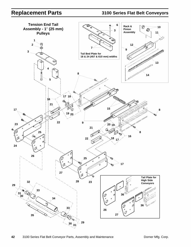
Replacement Parts 3100 Series Flat Belt Conveyors
42 3100 Series Flat Belt Conveyor Parts, Assembly and Maintenance Dorner Mfg. Corp.
Tension End TailAssembly - 1″ (25 mm)
Pulleys
Tail Plate forHigh SideConveyors
26
27
36
36
2932
29
17 18
19 20
1718
1920
16
16
7
311
13
610
12
14
9Tail Bed Plate for18 & 24 (457 & 610 mm) widths
Rack &PinionAssembly
30 31
34
35
33
33
3130
1
4
2
3
5
8
8
9
15
21
22
21
22
25
23
17
24
26
27
28
17
23
25
8

Replacement Parts3100 Series Flat Belt Conveyors
Dorner Mfg. Corp. 3100 Series Flat Belt Conveyor Parts, Assembly and Maintenance 43
Item Part No. Part Description 1 300158M Threaded Bushing
2 807-384 Spring Washer
3 301704 Tail Bedplate, Tension End, 4″ (95 mm)
301705 Tail Bedplate, Tension End, 5″ (127 mm)
301706 Tail Bedplate, Tension End, 6″ (152 mm)
301708 Tail Bedplate, Tension End, 8″ (203 mm)
301710 Tail Bedplate, Tension End, 10″ (254 mm)
301712 Tail Bedplate, Tension End, 12″ (305 mm)
301718M Tail Bedplate, Tension End, 18″ (457 mm)
301724M Tail Bedplate, Tension End, 24″ (610 mm)
4 300155M Bed-Link Mounting Block
5 920650M Socket Head Cap Screw, M6-1.0 x 50 mm
6 930512M Flat Head Cap Screw, M5-0.80 x 12 mm
7 303018M Bedplate Tail Bar, 18″ (457 mm)
303024M Bedplate Tail Bar, 24″ (610 mm)
8 920508M Socket Head Cap Screw, M5-0.80 x 8 mm
9 300169M Rack and Pinion Housing Ass’y
10 200034 Pinion Wear Ring
11 200151 Back Bowed Spring
12 300166M Take-up Rack Housing
13 300167 Rack Gear
14 300168 Wear Rack Strip
15 203004M Pinion Gear 4″ (95 mm)
203005M Pinion Gear 5″ (127 mm)
203006M Pinion Gear 6″ (152 mm)
203008M Pinion Gear 8″ (203 mm)
203010M Pinion Gear 10″ (254 mm)
203012M Pinion Gear 12″ (305 mm)
203018M Pinion Gear 18″ (457 mm)
203024M Pinion Gear 24″ (610 mm)
16 200331M Cam Mounting Ass’y
17 910612M Button Head Cap Screw, M6-1.0 x 12 mm
18 200038M Cam Clamping Plate
19 200341M Cam Retaining Block
20 200039M Belt Tracking Cam
21 300150M Drop-In T-bar
22 300152M T-bar
Item Part No. Part Description23 910506M Button Head Cap Screw, M5-0.80 x 6 mm
24 300030M Tail Cover Plate, Right Hand
25 930612M Flat Head Cap Screw, M6-1.0 x 12 mm
26 300064M Tail Plate, Right Hand (Low Side)
300062M Tail Plate, Right Hand (High Side)
27 300065M Tail Plate, Left Hand (Low Side)
300063M Tail Plate, Left Hand (High Side)
28 300031M Tail Cover Plate, Left Hand
29 300035M Retaining Sleeve Ass’y
30 300036M Retaining Sleeve
31 810-292 Grease Fitting
32 303104 Pulley Ass’y, 4″ (95 mm)
303105 Pulley Ass’y, 5″ (127 mm)
303106 Pulley Ass’y, 6″ (152 mm)
303108 Pulley Ass’y, 8″ (203 mm)
303110 Pulley Ass’y, 10″ (254 mm)
303112 Pulley Ass’y, 12″ (305 mm)
303118 Pulley Ass’y, 18″ (457 mm)
303124 Pulley Ass’y, 24″ (610 mm)
33 21-33 Bearing
34 302204 Pulley, 4″ (95 mm)
302205 Pulley, 5″ (127 mm)
302206 Pulley, 6″ (152 mm)
302208 Pulley, 8″ (203 mm)
302210 Pulley, 10″ (254 mm)
302212 Pulley, 12″ (305 mm)
302218 Pulley, 18″ (457 mm)
302224 Pulley, 24″ (610 mm)
35 302104 Pulley Shaft, 4″ (95 mm)
302105 Pulley Shaft, 5″ (127 mm)
302106 Pulley Shaft, 6″ (152 mm)
302108 Pulley Shaft, 8″ (203 mm)
302110 Pulley Shaft, 10″ (254 mm)
302112 Pulley Shaft, 12″ (305 mm)
302118 Pulley Shaft, 18″ (457 mm)
302124 Pulley Shaft, 24″ (610 mm)
36 300164M Filler Plate (High Side)
NOTE: Metric parts listed. For SAE parts, other than fasteners, drop the “M” suffix. SAE equivalent fasteners are identified in the table on page
73.

Replacement Parts 3100 Series Flat Belt Conveyors
44 3100 Series Flat Belt Conveyor Parts, Assembly and Maintenance Dorner Mfg. Corp.
0111
Note: Gearmotor is not included withmounting package. Square keyis included with gearmotor.See page 70.
Bottom Drive Mounting
8
5
19
3
2
20
11
9
12
1
4
6
7
10
14
13
21
15
16
Taper Lock
Assembly
17
1
14
1617
18
Item Part No. Part Description
1 980018M Square Key (Undersized), 6 mm x 18 mm
2 300349M Bottom Drive Cover
3 910406M Button Head Cap Screw, M4-0.70 x 6 mm
4 300038M Spacer, 3/8 Thick
5 310037M Drive Bottom Mounting Plate
6 300187 Idler Spacer Bar
7 300186M Idler Guide Bar
8 930625M Flat Head Cap Screw, M6-1.0 x 25 mm
9 628144M Cam Follower Nut 10 605284 Hard Washer, Black Oxide
11 802-059 Cam Follower Bearing 12 921250M Socket Head Cap Screw, M12-1.75 x 50 mm
13 920625M Socket Head Cap Screw, M6-1.0 x 25 mm
14 920620M Socket Head Cap Screw, M6-1.0 x 20 mm
15 920630M Socket Head Cap Screw, M6-1.0 x 30 mm
Item Part No. Part Description
16 811-126 Pulley, 16 Tooth, Taper Lock , TL-1108 811-127 Pulley, 18 Tooth, Taper Lock , TL-1210 811-133 Pulley, 14 Tooth, Taper Lock , TL-1108 811-135 Pulley, 20 Tooth, Taper Lock , TL-1210 811-136 Pulley, 22 Tooth, Taper Lock , TL-1610 811-137 Pulley, 24 Tooth, Taper Lock , TL-1610 17 811-206 Taper Lock Bushing, TL-1610, 19 mm Bore 811-205 Taper Lock Bushing, TL-1210, 19 mm Bore
811-204 Taper Lock Bushing, TL-1108, 19 mm Bore 18 300049M Drive Pulley, 19 Tooth, 19 mm Bore 19 970608M Socket Head Set Screw, M6-1.0 x 8 mm
20 814-047 Timing Belt, 21″ (533.4 mm) Long 814-048 Timing Belt, 22″ (558.8 mm) Long 814-057 Timing Belt, 23″ (584.2 mm) Long 21 920616M Socket Head Cap Screw, M6-1.0 x 16 mm
NOTE: Metric parts listed. For SAE parts, other than fasteners, drop the “M” suffix. SAE equivalent fasteners are identified in the table on page
73.

Replacement Parts3100 Series Flat Belt Conveyors
Dorner Mfg. Corp. 3100 Series Flat Belt Conveyor Parts, Assembly and Maintenance 45
Side Mounting Package
7
5
2
12
11
4
1
9
13
14
15
1
6
10
4
8
4
8
3
Note: Gearmotor is not in-cluded with mountingpackage. Square key isincluded with gearmo-tor. See page 70.
Item Part No. Part Description
1 980018M Square Key (Undersized), 6 mm x 18 mm 2 807-102
6Flexible Coupling, 19 mm
3 310047M Side Drive Gusset 4 920620M Socket Head Cap Screw, M6-1.0 x 20 mm 5 920625M Socket Head Cap Screw, M6-1.0 x 25 mm 6 920635M Socket Head Cap Screw, M6-1.0 x 35 mm
7 310039M Side Drive Mounting Plate 8 920520M Socket Head Cap Screw, M5-0.80 x 20
mm
Item Part No. Part Description
9 300038M Spacer, 3/8, Thick10 310048M Side Drive Guard
11 910510M Button Head Cap Screw, M5-0.80 x 10 mm12 310041M Gearmotor Mounting Plate13 930518M Flat Head Cap Screw, M5-0.80 x 18 mm14 920518M Socket Head Cap Screw, M5-0.80 x 18
mm15 310042M Side Drive Plate
NOTE: Metric parts listed. For SAE parts, other than fasteners, drop the “M” suffix. SAE equivalent fasteners are identified in the table on page
73.

Replacement Parts 3100 Series Flat Belt Conveyors
46 3100 Series Flat Belt Conveyor Parts, Assembly and Maintenance Dorner Mfg. Corp.
Top Drive Mounting Package
8
5
18
3
2
20
11
9
19
12
17
Taper Lock
Assembly
16
1
1 4
6
7
10
21
13
1415
16
17
14
Note: Gearmotor is not includedwith mounting package.Square key is includedwith gearmotor. See page70.
Item Part No. Part Description
1 980018M Square Key (Undersized), 6 mm x 18 mm
2 310046M Top Drive Cover 3 910406M Button Head Cap Screw, M4-0.70 x 10 mm 4 300038M Spacer, 3/8 Thick
5 310045M Drive Top Mounting Plate
6 300187 Idler Spacer Bar 7 300186M Idler Guide Bar 8 930625M Flat Head Cap Screw, M5-1.0 x 25 mm
9 628144M Cam Follower Nut 10 605284 Hard Washer, Black Oxide
11 802-059 Cam Follower Bearing 12 921250M Socket Head Cap Screw, M12-1.75 x 50
mm 13 920625M Socket Head Cap Screw, M6-1.0 x 25 mm 14 920620M Socket Head Cap Screw, M6-1.0 x 20 mm 15 920630M Socket Head Cap Screw, M6-1.0 x 30 mm
Item Part No. Part Description
16 811-126 Pulley, 16 Tooth, Taper Lock , TL-1108 811-127 Pulley, 18 Tooth, Taper Lock , TL-1210 811-133 Pulley, 14 Tooth, Taper Lock , TL-1108 811-135 Pulley, 20 Tooth, Taper Lock , TL-1210 811-136 Pulley, 22 Tooth, Taper Lock , TL-1610 811-137 Pulley, 24 Tooth, Taper Lock , TL-1610 17 811-206 Taper Lock Bushing, TL-1610, 19 mm
Bore 811-205 Taper Lock Bushing, TL-1210, 19 mm
Bore 811-204 Taper Lock Bushing, TL-1108, 19 mm
Bore 18 300049M Drive Pulley, 19 Tooth, 19 mm Bore 19 970608M Socket Head Set Screw, M6-1.0 x 8 mm 20 814-059 Timing Belt, 27″ (685 mm) Long 814-060 Timing Belt, 28″ (711 mm) Long 21 920616M Socket Head Cap Screw, M6-1.0 x 16 mm
NOTE: Metric parts listed. For SAE parts, other than fasteners, drop the “M” suffix. SAE equivalent fasteners are identified in the table on page
73.

Replacement Parts3100 Series Flat Belt Conveyors
Dorner Mfg. Corp. 3100 Series Flat Belt Conveyor Parts, Assembly and Maintenance 47
Vertical Center Drive – Visual IndexStandard Vertical Center Drive for 8″ (203 mm) wideconveyor shown. Parts Lists on following pages identify partsfor 4″ (95 mm), 5″ (127 mm), 6″ (152 mm), 8″ (203 mm), 10″(254 mm), 12″ (305 mm), 18″ (457 mm), 24″ (610 mm), 30″(762 mm), 36 (915 mm), and 40″ (1016 mm) wide conveyors.For any other sizes, please consult factory.
NOTE:Visual Index is provided to simplify location of parts andtheir relationships with each other. The drawings are notintended to be used for dissassembly or re-assemblyreferences.
Belt Tensioning and Idler PulleysExploded View and Parts List starts on page50
Side Plates, Covers and GuardsExploded View and Parts List starts on page 48
Drive Pulley, Timing Belt Pulleys,Timing Belt and Mounting PlatesExploded View and Parts List starts on page 52

Replacement Parts 3100 Series Flat Belt Conveyors
48 3100 Series Flat Belt Conveyor Parts, Assembly and Maintenance Dorner Mfg. Corp.
Vertical Center Drive – Side Plates, Covers & Guards
8
9
6
5 4
7
3 2
11
12
13
9
1510
1
18
16
2122
2
19
17
5
6
4 3
14
9
3
3 4
4
5
5
6
6
7
8
9
20
9
9
15
10
11
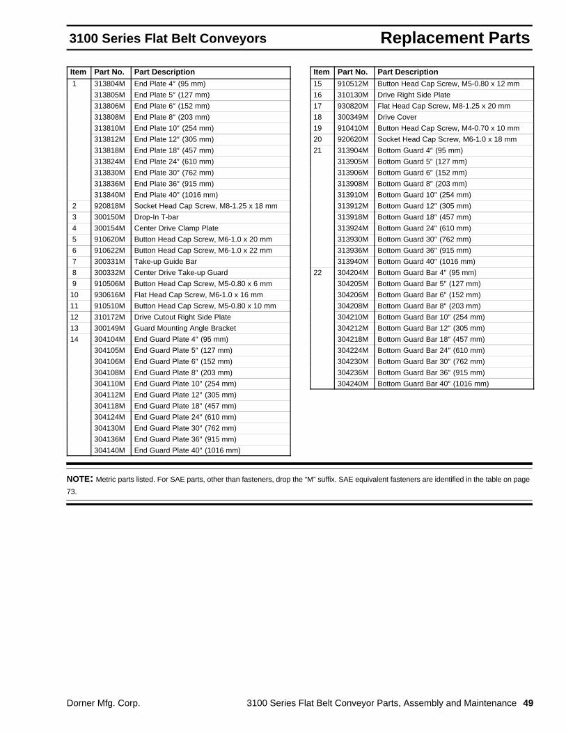
Replacement Parts3100 Series Flat Belt Conveyors
Dorner Mfg. Corp. 3100 Series Flat Belt Conveyor Parts, Assembly and Maintenance 49
Item Part No. Part Description 1 313804M End Plate 4″ (95 mm)
313805M End Plate 5″ (127 mm)
313806M End Plate 6″ (152 mm)
313808M End Plate 8″ (203 mm)
313810M End Plate 10″ (254 mm)
313812M End Plate 12″ (305 mm)
313818M End Plate 18″ (457 mm)
313824M End Plate 24″ (610 mm)
313830M End Plate 30″ (762 mm)
313836M End Plate 36″ (915 mm)
313840M End Plate 40″ (1016 mm)
2 920818M Socket Head Cap Screw, M8-1.25 x 18 mm
3 300150M Drop-In T-bar
4 300154M Center Drive Clamp Plate
5 910620M Button Head Cap Screw, M6-1.0 x 20 mm
6 910622M Button Head Cap Screw, M6-1.0 x 22 mm
7 300331M Take-up Guide Bar
8 300332M Center Drive Take-up Guard
9 910506M Button Head Cap Screw, M5-0.80 x 6 mm
10 930616M Flat Head Cap Screw, M6-1.0 x 16 mm
11 910510M Button Head Cap Screw, M5-0.80 x 10 mm
12 310172M Drive Cutout Right Side Plate
13 300149M Guard Mounting Angle Bracket
14 304104M End Guard Plate 4″ (95 mm)
304105M End Guard Plate 5″ (127 mm)
304106M End Guard Plate 6″ (152 mm)
304108M End Guard Plate 8″ (203 mm)
304110M End Guard Plate 10″ (254 mm)
304112M End Guard Plate 12″ (305 mm)
304118M End Guard Plate 18″ (457 mm)
304124M End Guard Plate 24″ (610 mm)
304130M End Guard Plate 30″ (762 mm)
304136M End Guard Plate 36″ (915 mm)
304140M End Guard Plate 40″ (1016 mm)
Item Part No. Part Description15 910512M Button Head Cap Screw, M5-0.80 x 12 mm
16 310130M Drive Right Side Plate
17 930820M Flat Head Cap Screw, M8-1.25 x 20 mm
18 300349M Drive Cover
19 910410M Button Head Cap Screw, M4-0.70 x 10 mm
20 920620M Socket Head Cap Screw, M6-1.0 x 18 mm
21 313904M Bottom Guard 4″ (95 mm)
313905M Bottom Guard 5″ (127 mm)
313906M Bottom Guard 6″ (152 mm)
313908M Bottom Guard 8″ (203 mm)
313910M Bottom Guard 10″ (254 mm)
313912M Bottom Guard 12″ (305 mm)
313918M Bottom Guard 18″ (457 mm)
313924M Bottom Guard 24″ (610 mm)
313930M Bottom Guard 30″ (762 mm)
313936M Bottom Guard 36″ (915 mm)
313940M Bottom Guard 40″ (1016 mm)
22 304204M Bottom Guard Bar 4″ (95 mm)
304205M Bottom Guard Bar 5″ (127 mm)
304206M Bottom Guard Bar 6″ (152 mm)
304208M Bottom Guard Bar 8″ (203 mm)
304210M Bottom Guard Bar 10″ (254 mm)
304212M Bottom Guard Bar 12″ (305 mm)
304218M Bottom Guard Bar 18″ (457 mm)
304224M Bottom Guard Bar 24″ (610 mm)
304230M Bottom Guard Bar 30″ (762 mm)
304236M Bottom Guard Bar 36″ (915 mm)
304240M Bottom Guard Bar 40″ (1016 mm)
NOTE: Metric parts listed. For SAE parts, other than fasteners, drop the “M” suffix. SAE equivalent fasteners are identified in the table on page
73.

Replacement Parts 3100 Series Flat Belt Conveyors
50 3100 Series Flat Belt Conveyor Parts, Assembly and Maintenance Dorner Mfg. Corp.
Take-up Bar for 18 to 40″(457 & 1016 mm) widths
Vertical Center Drive – Belt Tensioning & Idler Pulleys
1
7 & 8
2 3
4 5
A
A
D
C
C
B
B
Drive Roller(See Page 52)
4
9
1
2 3
6
4 5
6
7 & 8
7 & 8 4 9
4
9
9
8
4
4
13
14
15 16
1716
1413
4
15
18
19
19
25
18
2021
22
2324
26
10
11
12
7
D

Replacement Parts3100 Series Flat Belt Conveyors
Dorner Mfg. Corp. 3100 Series Flat Belt Conveyor Parts, Assembly and Maintenance 51
Item Part No. Part Description 1 300244M Tracking Cam Ass’y
2 915-999 External Retaining Ring, Truarc 5101-56
3 300191 Hardened Washer
4 910506M Button Head Cap Screw, M5-0.80 x 6 mm
5 300199 Cam Mounting Plate
6 623777M Tail Align Cam
7 326704 Idler Pulley Ass’y 4″ (95 mm)
326706 Idler Pulley Ass’y 6″ (152 mm)
326708 Idler Pulley Ass’y 8″ (203 mm)
326710 Idler Pulley Ass’y 10″ (254 mm)
326712 Idler Pulley Ass’y 12″ (305 mm)
326718 Idler Pulley Ass’y 18″ (457 mm)
326724 Idler Pulley Ass’y 24″ (610 mm)
326730 Idler Pulley Ass’y 30″ (762 mm)
326736 Idler Pulley Ass’y 36″ (915 mm)
326740 Idler Pulley Ass’y 40″ (1016 mm)
8 301904 Idler Shaft 4″ (95 mm) Wide
301905 Idler Shaft 5″ (127 mm) Wide
301906 Idler Shaft 6″ (152 mm) Wide
301907 Idler Shaft 7″ (178 mm) Wide
301908 Idler Shaft 8″ (203 mm) Wide
301910 Idler Shaft 10″ (254 mm) Wide
301912 Idler Shaft 12″ (305 mm) Wide
301918 Idler Shaft 18″ (457 mm) Wide
301924 Idler Shaft 24″ (610 mm) Wide
301930 Idler Shaft 30″ (762 mm) Wide
301936 Idler Shaft 36″ (915 mm) Wide
301940 Idler Shaft 40″ (1016 mm) Wide
9 200825 Shaft Retaining Clip
10 326604 Aluminum Pulley Tube, 4″ (95 mm)
326605 Aluminum Pulley Tube, 5″ (127 mm)
326606 Aluminum Pulley Tube, 6″ (152 mm)
326608 Aluminum Pulley Tube, 8″ (203 mm)
326610 Aluminum Pulley Tube, 10″ (254 mm)
326612 Aluminum Pulley Tube, 12″ (305 mm)
326618 Aluminum Pulley Tube, 18″ (457 mm)
326624 Aluminum Pulley Tube, 24″ (610 mm)
326630 Aluminum Pulley Tube, 30″ (762 mm)
326636 Aluminum Pulley Tube, 36″ (915 mm)
326640 Aluminum Pulley Tube, 40″ (1016 mm)
Item Part No. Part Description
11 802-110 Ball Bearing (Set Screws Removed)
12 915-051 Retaining Ring
13 300330 Take-up Outer Plate
14 300329M Take-up Inner Plate
15 304904 Take-up Bar 4″ (95 mm)
304905 Take-up Bar 5″ (127 mm)
304906 Take-up Bar 6″ (152 mm)
304908 Take-up Bar 8″ (203 mm)
304910 Take-up Bar 10″ (254 mm)
304912 Take-up Bar 12″ (305 mm)
304918 Take-up Bar 18″ (457 mm)
304924 Take-up Bar 24″ (610 mm)
304930 Take-up Bar 30″ (762 mm)
304936 Take-up Bar 36″ (915 mm)
304940 Take-up Bar 40″ (1016 mm)
16 915-002 Retaining Ring, Truarc 5101-15
17 300457 Pneumatic/Spring Tension Clevis Pin
18 920818M Socket Head Cap Screw, M8-1.25 x 18 mm
19 303704M Cylinder Mounting Plate 4″ (95 mm)
303705M Cylinder Mounting Plate 5″ (127 mm)
303706M Cylinder Mounting Plate 6″ (152 mm)
303708M Cylinder Mounting Plate 8″ (203 mm)
303710M Cylinder Mounting Plate 10″ (254 mm)
303712M Cylinder Mounting Plate 12″ (305 mm)
303718M Cylinder Mounting Plate 18″ (457 mm)
303724M Cylinder Mounting Plate 24″ (610 mm)
303730M Cylinder Mounting Plate 30″ (762 mm)
303736M Cylinder Mounting Plate 36″ (915 mm)
303740M Cylinder Mounting Plate 40″ (1016 mm)
20 51-19-08 Take-up Cylinder 2-1/2″ Bore, 4″ Stroke [4 to10″ (95 to 254 mm) Wide Conveyors Only]
300121P Take-up Cylinder 3″ Bore, 4″ Stroke [12 to 40″(305 to 1016 mm) Wide Conveyors Only]
21 825-084 Reducing Bushing 3/8 to 1/4 NPT [12 to 40″(305 to 1016 mm) Wide Conveyors Only]
22 825-081 Street Elbow, 1/4″ NPT
23 825-017 Nipple, 1/4″ NPT x 0.88″24 810-073 Pneumatic Regulator
25 300122M Stiffener Bar 24 to 40″ (610 to 1016 mm)
26 920618M Socket Head Cap Screw, M6-1.0 x 18 mm
NOTE: Metric parts listed. For SAE parts, other than fasteners, drop the “M” suffix. SAE equivalent fasteners are identified in the table on page
73.

Replacement Parts 3100 Series Flat Belt Conveyors
52 3100 Series Flat Belt Conveyor Parts, Assembly and Maintenance Dorner Mfg. Corp.
Vertical Center Drive – Drive Pulleys, Timing Belt Pulleys & Mounting Plates
1
2
3
4
17
7 8
10 9
11
12
13
14
15
16
2
5
19
3
7
6
18
5
Note: Gearmotor is not includedwith mounting package.Square key is includedwith gearmotor. See page70.

Replacement Parts3100 Series Flat Belt Conveyors
Dorner Mfg. Corp. 3100 Series Flat Belt Conveyor Parts, Assembly and Maintenance 53
Item Part No. Part Description 1 300124M Drawn Bearing Cover
2 910606M Button Head Cap Screw, M6-1.0 x 6 mm
3 310181 Bearing Ass’y
4 309604M Pulley Ass’y 4″ (95 mm)
309605M Pulley Ass’y 5″ (127 mm)
309606M Pulley Ass’y 6″ (152 mm)
309608M Pulley Ass’y 8″ (203 mm)
309610M Pulley Ass’y 10″ (254 mm)
309612M Pulley Ass’y 12″ (305 mm)
309618M Pulley Ass’y 18″ (457 mm)
309624M Pulley Ass’y 24″ (610 mm)
309630M Pulley Ass’y 30″ (762 mm)
309636M Pulley Ass’y 36″ (915 mm)
309640M Pulley Ass’y 40″ (1016 mm)
5 980018M Square Key (Undersized), 6 mm x 18 mm
6 811-201 14T Pulley, Taper Lock , TL-1108
811-139 16T Pulley, Taper Lock , TL-1108
Item Part No. Part Description
7 811-207 Taper Lock Bushing, TL-2012, 19 mmBore
811-206 Taper Lock Bushing, TL-1610, 19 mmBore
811-205 Taper Lock Bushing, TL-1210, 19 mmBore
811-204 Taper Lock Bushing, TL-1108, 19 mmBore
8 300187 Idler Spacer Bar
9 628144 Cam Follower Nut
10 300186M Idler Guide Bar
11 930625M Flat Head Cap Screw, M6-1.0 x 25 mm
12 605284 Hard Washer, Black Oxide
13 802-070 Solid Ball Bearing, Nice 1633DC
14 911-516 Hardened Flat Washer, Steel
15 904-213 Socket Head Shoulder Screw, 0.63 dia. x 1.5″16 814-049 Timing Belt, 21″ (533 mm) Long
814-050 Timing Belt, 22″ (559 mm) Long
17 811-151 18T Pulley, Taper Lock , TL-1210
811-142 20T Pulley, Taper Lock , TL-1210
811-143 22T Pulley, Taper Lock , TL-1610
811-164 24T Pulley, Taper Lock , TL-2012
18 300047M Pulley, 19 Tooth
300048M Pulley, 21 Tooth
19 970608M Cup Set Screw, M6-1.0 x 8 mm
NOTE: Metric parts listed. For SAE parts, other than fasteners, drop the “M” suffix. SAE equivalent fasteners are identified in the table on page
73.

Replacement Parts 3100 Series Flat Belt Conveyors
54 3100 Series Flat Belt Conveyor Parts, Assembly and Maintenance Dorner Mfg. Corp.
Intentionally Blank

Replacement Parts3100 Series Flat Belt Conveyors
Dorner Mfg. Corp. 3100 Series Flat Belt Conveyor Parts, Assembly and Maintenance 55
Horizontal Heavy Load Center Drive – Visual IndexHorizontal Heavy Load Center Drive for 8″ (203 mm) wideconveyor shown. Parts Lists on following pages identify partsfor 6″ (152 mm), 8″ (203 mm), 10″ (254 mm), 12″ (305 mm),18″ (457 mm), 24″ (610 mm), 30″ (762 mm), 36 (915 mm),and 40″ (1016 mm) wide conveyors. For any other sizes,please consult factory.
NOTE:Visual Index is provided to simplify location of parts andtheir relationships with each other. The drawings are notintended to be used for dissassembly or re-assemblyreferences.
Belt Tensioning and Idler PulleysExploded View and Parts List starts on page 58
Side Plates, Covers and GuardsExploded View and Parts List starts on page 56
Drive Pulley, Timing Belt Pulleys, TimingBelt and Mounting PlatesExploded View and Parts List starts on page 60

Replacement Parts 3100 Series Flat Belt Conveyors
56 3100 Series Flat Belt Conveyor Parts, Assembly and Maintenance Dorner Mfg. Corp.
Heavy Load Horizontal Center Drive – Side Plates, Covers & Guards
11
2
12
10
9
5
6 7
8
131415
16
17
18
19 20
1
3
4
23
Guard for10 to 40″
(254 to 1016 mm)widths
1
2
2
2
2
2
2 3
5
5 5
5
5
6
6
6
6
6
8
7
7
7
7
7
8
8
8
8
21
4
12
1513
11
2
22
22
4
4
4
4
4
4

Replacement Parts3100 Series Flat Belt Conveyors
Dorner Mfg. Corp. 3100 Series Flat Belt Conveyor Parts, Assembly and Maintenance 57
Item Part No. Part Description 1 305008M Center Drive End Guard 8″ (203 mm)
305010M Center Drive End Guard 10″ (254 mm)
305012M Center Drive End Guard 12″ (305 mm)
305018M Center Drive End Guard 18″ (457 mm)
305024M Center Drive End Guard 24″ (610 mm)
305030M Center Drive End Guard 30″ (762 mm)
305036M Center Drive End Guard 36″ (915 mm)
305040M Center Drive End Guard 40″ (1016 mm)
2 910506M Button Head Cap Screw, M5-0.80 x 6 mm
3 300149M Guard Mounting Angle Bracket
4 910510M Button Head Cap Screw, M5-0.80 x 10 mm
5 300150M Drop-In T-bar
6 300154M Center Drive Clamp Plate
7 910620M Button Head Cap Screw, M6-1.0 x 20 mm
8 910622M Button Head Cap Screw, M6-1.0 x 22 mm
9 300194M Sight Gauge Cover Plate
10 910606M Button Head Cap Screw, M6-1.0 x 6 mm
11 300185M Take-up Guard
12 930614M Flat Head Cap Screw, M6-1.0 x 14 mm
13 300184M Take-up Guide Bar
14 300198M Back Side Plate
15 910516M Button Head Cap Screw, M5-0.80 x 16 mm
16 305206M Bottom Guard Center Rail 6″ (152 mm)
305208M Bottom Guard Center Rail 8″ (203 mm)
305210M Bottom Guard Center Rail 10″ (254 mm)
305212M Bottom Guard Center Rail 12″ (305 mm)
305218M Bottom Guard Center Rail 18″ (457 mm)
305224M Bottom Guard Center Rail 24″ (610 mm)
305230M Bottom Guard Center Rail 30″ (762 mm)
305236M Bottom Guard Center Rail 36″ (915 mm)
305240M Bottom Guard Center Rail 40″ (1016 mm)
Item Part No. Part Description17 307206M Rail Nut Strip 6″ (152 mm) Wide
307208M Rail Nut Strip 8″ (203 mm) Wide
307210M Rail Nut Strip 10″ (254 mm) Wide
307212M Rail Nut Strip 12″ (305 mm) Wide
307208M307210M
Rail Nut Strips Combinedfor 18″ (457 mm) Wide
307212M307212M
Rail Nut Strips Combinedfor 24″ (610 mm) Wide
307210M307210M307210M
Rail Nut Strips Combinedfor 30″ (762 mm) Wide
307212M307212M307212M
Rail Nut Strips Combinedfor 36″ (915 mm) Wide
307210M307210M307210M307210M
Rail Nut Strips Combinedfor 40″ (1016 mm) Wide
18 307201 Spacer, Nut Strip for 18 to 40″(457 to 1016 mm) Widths Only
19 910410M Button Head Cap Screw, M4-0.70 x 10 mm
20 305106M Bottom Guard 6″ (152 mm)
305108M Bottom Guard 8″ (203 mm)
305110M Bottom Guard 10″ (254 mm)
305112M Bottom Guard 12″ (305 mm)
305108M305110M
Bottom Guards Combinedfor 18″ (457 mm)
305112M305112M
Bottom Guards Combinedfor 24″ (610 mm)
305110M305110M305110M
Bottom Guards Combinedfor 30″ (762 mm)
305112M305112M305112M
Bottom Guards Combinedfor 36″ (915 mm)
305110M305110M305110M305110M
Bottom Guards Combinedfor 40″ (1016 mm)
21 300197M Front Side Plate
22 300148M Cover Mounting Angle Bracket
23 300340M Double Drive Cover
NOTE: Metric parts listed. For SAE parts, other than fasteners, drop the “M” suffix. SAE equivalent fasteners are identified in the table on page
73.

Replacement Parts 3100 Series Flat Belt Conveyors
58 3100 Series Flat Belt Conveyor Parts, Assembly and Maintenance Dorner Mfg. Corp.
7 & 9
Heavy Load Horizontal Center Drive – Belt Tensioning & Idler Pulleys
6
2 3 4
5
13
15
6
6
6
12
12
14
6
17
6
2 3
4 5 9
7 & 9
19
21
22
23
20
18
24
A
AD
D
C
C
B
B
Drive Rollers(See Page 60)
25
15
19
26
Take-up Bar, Stiffener Bar &Cylinder Mounting Plate
for 24 to 40″ (610 to 1016 mm) widths
13 14
17
16
1
1
7
8
1110
7 & 9

Replacement Parts3100 Series Flat Belt Conveyors
Dorner Mfg. Corp. 3100 Series Flat Belt Conveyor Parts, Assembly and Maintenance 59
Item Part No. Part Description 1 300244M Tracking Cam Ass’y
2 915-999 External Retaining Ring, Truarc 5101-56
3 300191 Hardened Washer
4 300199 Cam Mounting Plate
5 623777M Tail Align Cam
6 910506M Button Head Cap Screw, M5-0.80 x 6 mm
7 306706 Idler Pulley Ass’y 6″ (152 mm)
306708 Idler Pulley Ass’y 8″ (203 mm)
306710 Idler Pulley Ass’y 10″ (254 mm)
306712 Idler Pulley Ass’y 12″ (305 mm)
306718 Idler Pulley Ass’y 18″ (457 mm)
306724 Idler Pulley Ass’y 24″ (610 mm)
306730 Idler Pulley Ass’y 30″ (762 mm)
306736 Idler Pulley Ass’y 36″ (915 mm)
306740 Idler Pulley Ass’y 40″ (1016 mm)
8 326604 Aluminum Pulley Tube, 4″ (95 mm)
326605 Aluminum Pulley Tube, 5″ (127 mm)
326606 Aluminum Pulley Tube, 6″ (152 mm)
326608 Aluminum Pulley Tube, 8″ (203 mm)
326610 Aluminum Pulley Tube, 10″ (254 mm)
326612 Aluminum Pulley Tube, 12″ (305 mm)
326618 Aluminum Pulley Tube, 18″ (457 mm)
326624 Aluminum Pulley Tube, 24″ (610 mm)
326630 Aluminum Pulley Tube, 30″ (762 mm)
326636 Aluminum Pulley Tube, 36″ (915 mm)
326640 Aluminum Pulley Tube, 40″ (1016 mm)
9 301906 Idler Shaft 6″ (152 mm) Wide
301908 Idler Shaft 8″ (203 mm) Wide
301910 Idler Shaft 10″ (254 mm) Wide
301912 Idler Shaft 12″ (305 mm) Wide
301918 Idler Shaft 18″ (457 mm) Wide
301924 Idler Shaft 24″ (610 mm) Wide
301930 Idler Shaft 30″ (762 mm) Wide
301936 Idler Shaft 36″ (915 mm) Wide
301940 Idler Shaft 40″ (1016 mm) Wide
Item Part No. Part Description
10 915-051 Retaining Ring
11 802-110 Ball Bearing (Set Screws Removed)
12 200825 Shaft Retaining Clip
13 300182 Outer Take-up Plate
14 300183M Inner Take-up Plate
15 304906 Take-up Bar 6″ (152 mm)
304908 Take-up Bar 8″ (203 mm)
304910 Take-up Bar 10″ (254 mm)
304912 Take-up Bar 12″ (305 mm)
304918 Take-up Bar 18″ (457 mm)
304924 Take-up Bar 24″ (610 mm)
304930 Take-up Bar 30″ (762 mm)
304936 Take-up Bar 36″ (915 mm)
304940 Take-up Bar 40″ (1016 mm)
16 300457 Pneumatic/Spring Tension Clevis Pin
17 915-007 Retaining Ring, Truarc 5100-25
18 906-155 Hex. Hd. Cap Screw, 3/8-24 x 1.0″ Long
19 304306M Cylinder Mounting Plate 6″ (152 mm)
304308M Cylinder Mounting Plate 8″ (203 mm)
304310M Cylinder Mounting Plate 10″ (254 mm)
304312M Cylinder Mounting Plate 12″ (305 mm)
304318M Cylinder Mounting Plate 18″ (457 mm)
304324M Cylinder Mounting Plate 24″ (610 mm)
304330M Cylinder Mounting Plate 30″ (762 mm)
304336M Cylinder Mounting Plate 36″ (915 mm)
304340M Cylinder Mounting Plate 40″ (1016 mm)
20 920818M Socket Head Cap Screw, M8-1.25 x 18 mm
21 300251P Take-up Cylinder 4″ Diameter, 4″ Stroke
22 825-081 Street Elbow, 1/4″ NPT
23 825-017 Nipple, 1/4″ NPT x 0.88″24 810-073 Pneumatic Regulator w/Gauge
25 300122M Stiffener Bar 24 to 40″ (610 to 1016 mm)
26 920625M Socket Head Cap Screw, M6-1.0 x 25 mm
NOTE: Metric parts listed. For SAE parts, other than fasteners, drop the “M” suffix. SAE equivalent fasteners are identified in the table on page
73.

Replacement Parts 3100 Series Flat Belt Conveyors
60 3100 Series Flat Belt Conveyor Parts, Assembly and Maintenance Dorner Mfg. Corp.
Heavy Load HorizontalCenter Drive – Drive Pulleys, Poly-V Belt Pulleys & Mounting Plates
Note: Gearmotor isnot includedwithmountingpackage.Square key isincluded withgearhead.See page 72.
1
3
4
5
8
9
11
10
7
626
26
25
23
2221
33
323130
28
27
29
19
18
20
14
17
18
16
12
2
13
14
13
15
1516
17
19
17
18
20
17
18
1
4
18 to 40″(457 to 1016 mm)
widths
6 to 12″(152 to 305 mm)
widths
0398

Replacement Parts3100 Series Flat Belt Conveyors
Dorner Mfg. Corp. 3100 Series Flat Belt Conveyor Parts, Assembly and Maintenance 61
Item Part No. Part Description 1 807-036 Oil Sight Gauge
2 825-022 Nipple, 1/4″ NPT x 3.0″ (70 mm)for 24 to 40″ (610 to 1016 mm) Widths Only
3 825-094 90° Female Elbow, 1/4″ to 1/4″ NPTfor 24 to 40″ (610 to 1016 mm) Widths Only
4 825-110 Nipple, 1/4″ NPT x 1.38″for 6″ (152 mm) Width Only
825-022 Nipple, 1/4″ NPT x 3″ (76 mm)for 8″ (203 mm) Width Only
825-026 Nipple, 1/4″ NPT x 5″for 10″ (254 mm) Width Only
825-029 Nipple, 1/4″ NPT x 7″for 12″ (305 mm) Width Only
825-019 Nipple, 1/4″ NPT x 1.5″ (35 mm)for 18 to 40″ (610 to 1016 mm) Widths Only
5 316706M Gearhead Support Plate 6″ (152 mm)
316708M Gearhead Support Plate 8″ (203 mm)
316710M Gearhead Support Plate 10″ (254 mm)
316712M Gearhead Support Plate 12″ (305 mm)
316718M Gearhead Support Plate 18″ (457 mm)
316724M Gearhead Support Plate 24″ (610 mm)
316730M Gearhead Support Plate 30″ (762 mm)
316736M Gearhead Support Plate 36″ (915 mm)
316740M Gearhead Support Plate 40″ (1016 mm)
6 902-181 Socket Hd. Cap Screw, 5/16-18 x 1.0″ 7 920818M Socket Head Cap Screw, M8-1.25 x 18 mm
8 811-225 3.15″ (80 mm) Dia. Poly-V Pulley
811-226 4.5″ (114 mm) Dia. Poly-V Pulley
9 811-011 Split Bushing, Type H, 1″ Dia. Bore
811-219 Split Bushing, Type P1, 1″ Dia. Bore
10 902-181 Socket Head Cap Screw, 5/16-18 x 1.0″11 912-103 Square Key, 1/4″ Sq. x 0.75″12 814-076 Poly-V Belt, 32″ (813 mm) long,
Gates 320J16
814-077 Poly-V Belt, 30″ (762 mm) long,Gates 300J16
814-078 Poly-V Belt, 28″ (711 mm) long,Gates 280J16
Item Part No. Part Description
13 980625M Square Key, 6 mm x 25 mm
14 902-134 Socket Head Cap Screw, 1/4-20 x 0.88″15 811-227 Split Bushing, Type G, 19 mm Dia. Bore
811-228 Split Bushing, Type H, 19 mm Dia. Bore
16 811-221 2.5″ (63.5 mm) Dia. Poly-V Pulley
811-222 2.65″ (67 mm) Dia. Poly-V Pulley
811-223 2.8″ (71 mm) Dia. Poly-V Pulley
811-224 3″ (76 mm) Dia. Poly-V Pulley
811-225 3.15″ (80 mm) Dia. Poly-V Pulley
17 910606M Button Head Cap Screw, M6-1.0 x 6 mm
18 310181 Bearing Ass’y
19 300124M Drawn Bearing Cover
20 309606M Pulley, 6″ (152 mm)
309608M Pulley, 8″ (203 mm)
309610M Pulley, 10″ (254 mm)
309612M Pulley, 12″ (305 mm)
309618M Pulley, 18″ (457 mm)
309624M Pulley, 24″ (610 mm)
309630M Pulley, 30″ (762 mm)
309636M Pulley, 36″ (915 mm)
309640M Pulley, 40″ (1016 mm)
21 904-213 Socket Head Shoulder Screw, 0.63″ dia. x1.50″
22 911-516 Hardened Flat Washer, Steel
23 802-070 Solid Ball Bearing, Nice 1633DC
24 300186M Idler Guide Bar
25 930625M Flat Head Cap Screw, M6-1.0 x 25 mm
26 300187 Idler Spacer Bar
27 920520M Socket Head Cap Screw, M5-0.80 x 20 mm
28 920540M Socket Head Cap Screw, M5-0.80 x 40 mm
29 300481M Stop Clamp Plate
30 300480M Spring Tensioner Clamp Block
31 990508M Nut, M5-0.80
32 807-806 Die Spring
33 300479 Tensioner Slide Bar
NOTE: Metric parts listed. For SAE parts, other than fasteners, drop the “M” suffix. SAE equivalent fasteners are identified in the table on page
73.

Replacement Parts 3100 Series Flat Belt Conveyors
62 3100 Series Flat Belt Conveyor Parts, Assembly and Maintenance Dorner Mfg. Corp.
Intentionally Blank

Replacement Parts3100 Series Flat Belt Conveyors
Dorner Mfg. Corp. 3100 Series Flat Belt Conveyor Parts, Assembly and Maintenance 63
Horizontal Standard Load Center Drive – Visual IndexHorizontal Standard Load Center Drive for 8″ (203 mm) wideconveyor shown. Parts Lists on following pages identify partsfor 4″ (95 mm), 5″ (127 mm), 6″ (152 mm), 8″ (203 mm), 10″(254 mm), 12″ (305 mm), 18″ (457 mm), 24″ (610 mm), 30″(762 mm), 36 (915 mm), and 40″ (1016 mm) wide conveyors.For any other sizes, please consult factory.
NOTE:Visual Index is provided to simplify location of parts andtheir relationships with each other. The drawings are notintended to be used for dissassembly or re-assemblyreferences.
Belt Tensioning and Idler PulleysExploded View and Parts List starts on page 66
Side Plates, Covers and GuardsExploded View and Parts List starts on page 64
Drive Pulley, Timing Belt Pulleys, Timing Beltand Mounting PlatesExploded View and Parts List starts on page 68

Replacement Parts 3100 Series Flat Belt Conveyors
64 3100 Series Flat Belt Conveyor Parts, Assembly and Maintenance Dorner Mfg. Corp.
Standard Load Horizontal Center Drive – Side Plates, Covers & Guards
8
20
7
3
4 5
6
101112
13
14
15
16 17
22
1
2
21
9
3 3
3
3
4
4
4
4
5
5
5
5
6
6
6
6
18
20
19
19 9
9
9
9
8 7
10
12
21
21
2

Replacement Parts3100 Series Flat Belt Conveyors
Dorner Mfg. Corp. 3100 Series Flat Belt Conveyor Parts, Assembly and Maintenance 65
Item Part No. Part Description 1 316404M End Plate 4″ (95 mm)
316405M End Plate 5″ (127 mm)
316406M End Plate 6″ (152 mm)
316408M End Plate 8″ (203 mm)
316410M End Plate 10″ (254 mm)
316412M End Plate 12″ (305 mm)
316418M End Plate 18″ (457 mm)
316424M End Plate 24″ (610 mm)
316430M End Plate 30″ (762 mm)
316436M End Plate 36″ (915 mm)
316440M End Plate 40″ (1016 mm)
2 920818M Socket Head Cap Screw, M8-1.25 x 18 mm
3 300150M Drop-In T-bar
4 300154M Center Drive Clamp Plate
5 910620M Button Head Cap Screw, M6-1.0 x 20 mm
6 910622M Button Head Cap Screw, M6-1.0 x 22 mm
7 930614M Flat Head Cap Screw, M6-1.0 x 14 mm
8 300185M Take-up Guard
9 910506M Button Head Cap Screw, M5-0.80 x 6 mm
10 300184M Take-up Guide Bar
11 310243M Back Side Plate
12 910516M Button Head Cap Screw, M5-0.80 x 16 mm
13 305204M Bottom Guard Center Rail 4″ (95 mm)
202807M Center Rail 5″ (127 mm)
202808M Center Rail 6″ (152 mm)
202810M Center Rail 8″ (203 mm)
202812M Center Rail 10″ (254 mm)
305212M Bottom Guard Center Rail 12″ (305 mm)
305218M Bottom Guard Center Rail 18″ (457 mm)
305224M Bottom Guard Center Rail 24″ (610 mm)
305230M Bottom Guard Center Rail 30″ (762 mm)
305236M Bottom Guard Center Rail 36″ (915 mm)
305240M Bottom Guard Center Rail 40″ (1016 mm)
Item Part No. Part Description14 307204M Rail Nut Strip 4″ (95 mm) Wide
307205M Rail Nut Strip 5″ (127 mm) Wide
307206M Rail Nut Strip 6″ (152 mm) Wide
307208M Rail Nut Strip 8″ (203 mm) Wide
307210M Rail Nut Strip 10″ (254 mm) Wide
307212M Rail Nut Strip 12″ (305 mm) Wide
307208M307210M
Rail Nut Strips Combinedfor 18″ (457 mm) Wide
307212M307212M
Rail Nut Strips Combinedfor 24″ (610 mm) Wide
307210M307210M307210M
Rail Nut Strips Combinedfor 30″ (762 mm) Wide
307212M307212M307212M
Rail Nut Strips Combinedfor 36″ (915 mm) Wide
307210M307210M307210M307210M
Rail Nut Strips Combinedfor 40″ (1016 mm) Wide
15 307201 Spacer, Nut Strip
16 910410M Button Head Cap Screw, M4-0.70 x 10 mm
17 305104M Bottom Guard 4″ (95 mm)
305105M Bottom Guard 5″ (127 mm)
305106M Bottom Guard 6″ (152 mm)
305108M Bottom Guard 8″ (203 mm)
305110M Bottom Guard 10″ (254 mm)
305112M Bottom Guard 12″ (305 mm)
305108M305110M
Bottom Guards Combinedfor 18″ (457 mm)
305112M305112M
Bottom Guards Combinedfor 24″ (610 mm)
305110M305110M305110M
Bottom Guards Combinedfor 30″ (762 mm)
305112M305112M305112M
Bottom Guards Combinedfor 36″ (915 mm)
305110M305110M305110M305110M
Bottom Guards Combinedfor 40″ (1016 mm)
18 310197M Front Side Plate
19 300148M Guard Mounting Angle Bracket
20 920618M Socket Head Cap Screw, M6-1.0 x 18 mm
21 910508M Button Head Cap Screw, M5-0.80 x 8 mm
22 300340M Double Drive Cover
NOTE: Metric parts listed. For SAE parts, other than fasteners, drop the “M” suffix. SAE equivalent fasteners are identified in the table on page
73.

Replacement Parts 3100 Series Flat Belt Conveyors
66 3100 Series Flat Belt Conveyor Parts, Assembly and Maintenance Dorner Mfg. Corp.
Standard Load Horizontal Center Drive – Belt Tensioning & Idler Pulleys
25
2 3 4
5
13
15
6
6
6
12
12
14
6
17
1
6
2 3
4 5
Take-up Bar, Stiffener Bar &Cylinder Mounting Plate
for 24 to 40″ (610 to 1016 mm) widths
9
7 & 9
15
19
26
19
21
22
23
24
20
18
19
27
2223
21
RegulatorAssemblyFor 4 & 5″
(95 & 127 mm)widths
RegulatorAssembly
For 6 to 40″(152 to 1016 mm)
widths
24
A
A
D
D
C
C
B
B
Drive Rollers(See Page 68)
13 14
17
16
7 & 9
7 & 9
6 1
7
8
10
11

Replacement Parts3100 Series Flat Belt Conveyors
Dorner Mfg. Corp. 3100 Series Flat Belt Conveyor Parts, Assembly and Maintenance 67
Item Part No. Part Description 1 300244M Tracking Cam Ass’y
2 915-999 External Retaining Ring, Truarc 5101-56
3 300191 Hardened Washer
4 300199 Cam Mounting Plate
5 623777M Tail Align Cam
6 910506M Button Head Cap Screw, M5-0.80 x 6 mm
7 306706 Idler Pulley Ass’y 6″ (152 mm)
306708 Idler Pulley Ass’y 8″ (203 mm)
306710 Idler Pulley Ass’y 10″ (254 mm)
306712 Idler Pulley Ass’y 12″ (305 mm)
306718 Idler Pulley Ass’y 18″ (457 mm)
306724 Idler Pulley Ass’y 24″ (610 mm)
306730 Idler Pulley Ass’y 30″ (762 mm)
306736 Idler Pulley Ass’y 36″ (915 mm)
306740 Idler Pulley Ass’y 40″ (1016 mm)
8 326604 Aluminum Pulley Tube, 4″ (95 mm)
326605 Aluminum Pulley Tube, 5″ (127 mm)
326606 Aluminum Pulley Tube, 6″ (152 mm)
326608 Aluminum Pulley Tube, 8″ (203 mm)
326610 Aluminum Pulley Tube, 10″ (254 mm)
326612 Aluminum Pulley Tube, 12″ (305 mm)
326618 Aluminum Pulley Tube, 18″ (457 mm)
326624 Aluminum Pulley Tube, 24″ (610 mm)
326630 Aluminum Pulley Tube, 30″ (762 mm)
326636 Aluminum Pulley Tube, 36″ (915 mm)
326640 Aluminum Pulley Tube, 40″ (1016 mm)
9 301904 Idler Shaft 4″ (95 mm) Wide
301905 Idler Shaft 5″ (127 mm) Wide
301906 Idler Shaft 6″ (152 mm) Wide
301907 Idler Shaft 7″ (178 mm) Wide
301908 Idler Shaft 8″ (203 mm) Wide
301910 Idler Shaft 10″ (254 mm) Wide
301912 Idler Shaft 12″ (305 mm) Wide
301918 Idler Shaft 18″ (457 mm) Wide
301924 Idler Shaft 24″ (610 mm) Wide
301930 Idler Shaft 30″ (762 mm) Wide
301936 Idler Shaft 36″ (915 mm) Wide
301940 Idler Shaft 40″ (1016 mm) Wide
10 802-110 Ball Bearing (Set Screws Removed)
11 915-051 Retaining Ring
Item Part No. Part Description
12 200825 Shaft Retaining Clip
13 300182 Outer Take-up Plate
14 300183M Inner Take-up Plate
15 304904 Take-up Bar 4″ (95 mm)
304905 Take-up Bar 5″ (127 mm)
304906 Take-up Bar 6″ (152 mm)
304908 Take-up Bar 8″ (203 mm)
304910 Take-up Bar 10″ (254 mm)
304912 Take-up Bar 12″ (305 mm)
304918 Take-up Bar 18″ (457 mm)
304924 Take-up Bar 24″ (610 mm)
304930 Take-up Bar 30″ (762 mm)
304936 Take-up Bar 36″ (915 mm)
304940 Take-up Bar 40″ (1016 mm)
16 300457 Pneumatic/Spring Tension Clevis Pin
17 915-002 Retaining Ring, Truarc 5100-15
18 906-155 Hex. Hd. Cap Screw, 3/8-24 x 1.0″ Long
19 304304M Cylinder Mounting Plate 4″ (95 mm)
304305M Cylinder Mounting Plate 5″ (127 mm)
304306M Cylinder Mounting Plate 6″ (152 mm)
304308M Cylinder Mounting Plate 8″ (203 mm)
304310M Cylinder Mounting Plate 10″ (254 mm)
304312M Cylinder Mounting Plate 12″ (305 mm)
304318M Cylinder Mounting Plate 18″ (457 mm)
304324M Cylinder Mounting Plate 24″ (610 mm)
304330M Cylinder Mounting Plate 30″ (762 mm)
304336M Cylinder Mounting Plate 36″ (915 mm)
304340M Cylinder Mounting Plate 40″ (1016 mm)
20 920818M Socket Head Cap Screw, M8-1.25 x 18 mm
21 300121P Take-up Cylinder 3″ Bore, 4″ Stroke for4 & 5″ (95 & 127 mm) Widths
300251P Take-up Cylinder 4″ Diameter, 4″ Strokefor 24 to 40″ (610 to 1016 mm) Widths
22 825-081 Street Elbow, 1/4″ NPT
23 825-017 Nipple, 1/4″ NPT x 0.88″24 810-073 Pneumatic Regulator w/Gauge
25 300122M Stiffener Bar 24 to 40″ (610 to 1016 mm)
26 920625M Socket Head Cap Screw, M6-1.0 x 25 mm
27 825-084 Reducing Bushing 3/8 to 1/4 NPT
NOTE: Metric parts listed. For SAE parts, other than fasteners, drop the “M” suffix. SAE equivalent fasteners are identified in the table on page
73.

Replacement Parts 3100 Series Flat Belt Conveyors
68 3100 Series Flat Belt Conveyor Parts, Assembly and Maintenance Dorner Mfg. Corp.
Standard Load HorizontalCenter Drive – Drive Pulleys, Poly-V Belt Pulleys & Mounting Plates
1
2
3
4
19
17
18
16
15
14
26
25
24
23
21
20
22
13
11
12
7
10
11
9
5
6
7
6
8
10
13
10
11
12
10
11
9
8
Note: Gearmotor is not includedwith mounting package.Square key is included withgearmotor. See page 70.
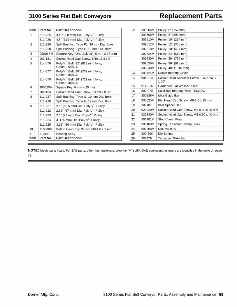
Replacement Parts3100 Series Flat Belt Conveyors
Dorner Mfg. Corp. 3100 Series Flat Belt Conveyor Parts, Assembly and Maintenance 69
Item Part No. Part Description 1 811-225 3.15″ (80 mm) Dia. Poly-V Pulley
811-226 4.5″ (114 mm) Dia. Poly-V Pulley
2 811-229 Split Bushing, Type P1, 19 mm Dia. Bore
811-228 Split Bushing, Type H, 19 mm Dia. Bore
3 980018M Square Key (Undersized), 6 mm x 18 mm
4 902-181 Socket Head Cap Screw, 5/16-18 x 1.0″ 5 814-076 Poly-V Belt, 32″ (813 mm) long,
Gates 320J16
814-077 Poly-V Belt, 30″ (762 mm) long,Gates 300J16
814-078 Poly-V Belt, 28″ (711 mm) long,Gates 280J16
6 980625M Square Key, 6 mm x 25 mm
7 902-134 Socket Head Cap Screw, 1/4-20 x 0.88″ 8 811-227 Split Bushing, Type G, 19 mm Dia. Bore
811-228 Split Bushing, Type H, 19 mm Dia. Bore
9 811-221 2.5″ (63.5 mm) Dia. Poly-V Pulley
811-222 2.65″ (67 mm) Dia. Poly-V Pulley
811-223 2.8″ (71 mm) Dia. Poly-V Pulley
811-224 3″ (76 mm) Dia. Poly-V Pulley
811-225 3.15″ (80 mm) Dia. Poly-V Pulley
10 910606M Button Head Cap Screw, M6-1.0 x 6 mm
11 310181 Bearing Ass’yItem Part No. Part Description
12 309606M Pulley, 6″ (152 mm)
309608M Pulley, 8″ (203 mm)
309610M Pulley, 10″ (254 mm)
309612M Pulley, 12″ (305 mm)
309618M Pulley, 18″ (457 mm)
309624M Pulley, 24″ (610 mm)
309630M Pulley, 30″ (762 mm)
309636M Pulley, 36″ (915 mm)
309640M Pulley, 40″ (1016 mm)
13 300124M Drawn Bearing Cover
14 904-213 Socket Head Shoulder Screw, 0.63″ dia. x1.50″
15 911-516 Hardened Flat Washer, Steel
16 802-070 Solid Ball Bearing, Nice 1633DC
17 300186M Idler Guide Bar
18 930625M Flat Head Cap Screw, M6-1.0 x 25 mm
19 300187 Idler Spacer Bar
20 920520M Socket Head Cap Screw, M5-0.80 x 20 mm
21 920540M Socket Head Cap Screw, M5-0.80 x 40 mm
22 300481M Stop Clamp Plate
23 300480M Spring Tensioner Clamp Block
24 990508M Nut, M5-0.80
25 807-806 Die Spring
26 300479 Tensioner Slide Bar
NOTE: Metric parts listed. For SAE parts, other than fasteners, drop the “M” suffix. SAE equivalent fasteners are identified in the table on page
73.

Replacement Parts 3100 Series Flat Belt Conveyors
70 3100 Series Flat Belt Conveyor Parts, Assembly and Maintenance Dorner Mfg. Corp.
Standard Load Gearmotors A
Fixed SpeedSingle-phase115 Volt A.C.60 Hz Motor
B
ItemMotor
Part No. hpGearRatio
OutputRPM
TorqueIn-Lb
A 62M180PS411F(n) 0.08 180:1 9.4 34162M060PS411F(n) 0.17 60:1 28 27032M030PS411F(n) 0.33 30:1 57 25032M020PS411F(n) 0.33 20:1 85 16732M010PS411F(n) 0.33 10:1 170 10832M005PS411F(n) 0.33 5:1 340 56
B 912-080 3/16″ x 1″ Square Key
(n) = Reversing CapacityN = Non-ReversingR = Reversing
Fixed SpeedThree-phase230/460 Volts A.C.60 HZ Motor
C
B
ItemMotor
Part No. hpGearRatio
OutputRPM
TorqueIn-Lb
B 912-080 3/16″ x 1″ Square Key
C 62M060PS423FN* 0.25 60:1 28 27032M030PS423FN 0.5 30:1 57 25032M020PS423FN 0.5 20:1 85 16732M010PS423FN 0.5 10:1 170 108
* Not available in 460 voltage.

Replacement Parts3100 Series Flat Belt Conveyors
Dorner Mfg. Corp. 3100 Series Flat Belt Conveyor Parts, Assembly and Maintenance 71
Standard Load 130 volt D.C. Variable Speed Motors & 115 volt A.C., 60 Hz. Controllers
F EDB
ItemMotor
Part No. hpGearRatio
OutputRPM
TorqueIn-Lb
B 912-080 3/16″ x 1″ Square Key
D 62M180PSD3DEN 0.12 180:1 14 34162M060PSD3DEN 0.25 60:1 42 27062M030PSD3DEN 0.25 30:1 83 13562M020PSD3DEN 0.25 20:1 125 9062M010PSD3DEN 0.33 10:1 250 72
ItemControllerPart No. Reversing Amperes Input
F 62MD1134 no 3 115 Volts, 60 Hz
E 62MD1134R yes 5
115 Volts, 60 HzSingle Phase

Replacement Parts 3100 Series Flat Belt Conveyors
72 3100 Series Flat Belt Conveyor Parts, Assembly and Maintenance Dorner Mfg. Corp.
Heavy Load Gearheads
I
G
H
VariableFrequency
Drive
Replacement Gearheads include four (4) 3/8-16 x 1″hexagon head cap screws and four (4) 3/8 lockwashers.
Item Part No. Part Description
G 32M060L Gear Reducer with 60 to 1 Ratio
32M040L Gear Reducer with 40 to 1 Ratio
32M025L Gear Reducer with 25 to 1 Ratio
32M020L Gear Reducer with 20 to 1 Ratio
32M010L Gear Reducer with 10 to 1 Ratio
32M005L Gear Reducer with 5 to 1 Ratio
H 912-103 Square Key, 1/4″ Sq. x 0.75″I Fixed Speed Single Phase 115 volts A.C.
32M2118 0.5 hp Motor
32M4118 1.0 hp Motor
Fixed Speed Single Phase 230 volts A.C.
32M2218 0.5 hp Motor
32M4218 1.0 hp Motor
32M7218 1.5 hp Motor
Fixed Speed Three- Phase 208-230 volts A.C.
32M2238 0.5 hp Motor
32M4238 1.0 hp Motor
32M7238 1.5 hp Motor
Fixed Speed Three-Phase 460 volts A.C.
32M2438 0.5 hp Motor
32M4438 1.0 hp Motor
32M7438 1.5 hp Motor
Variable Frequency 230 volts
32M2238-7 0.5 hp Motor
32M4238-7 1.0 hp Motor
32M7238-7 1.5 hp Motor
Variable Frequency 460 volts
32M2438-7 0.5 hp Motor
32M4438-7 1.0 hp Motor
32M7438-7 1.5 hp Motor

Replacement Parts3100 Series Flat Belt Conveyors
Dorner Mfg. Corp. 3100 Series Flat Belt Conveyor Parts, Assembly and Maintenance 73
Metric to SAE Hardware Conversion Table
MetricPart No. Hardware Name Metric Size Pages Appearing On
Equiv. SAEPart No.
Equiv.SAE Size
910406M Button Head Cap Screw M4-0.70 x 6 mm 44, 46 901-056 #8-32 x 1/4″910410M Button Head Cap Screw M4-0.70 x 10 mm 65 901-056 #8-32 x 1/4″910506M Button Head Cap Screw M5-0.80 x 6 mm 35, 37, 39, 41, 43, 49,
51, 57, 65, 75
901-104 #10-32 x 1/4″
910508M Button Head Cap Screw M5-0.80 x 8 mm 39, 65 901-105 #10-32 x 5/16″910510M Button Head Cap Screw M5-0.80 x 10 mm 45, 49, 57 901-106 #10-32 x 3/8″910512M Button Head Cap Screw M5-0.80 x 12 mm 49 901-108 #10-32 x 1/2″910516M Button Head Cap Screw M5-0.80 x 16 mm 30, 32, 57, 65 901-110 #10-32 x 5/8″910525M Button Head Cap Screw M5-0.80 x 25 mm 30, 32 901-116 #10-32 x 1″910606M Button Head Cap Screw M6-1.0 x 6 mm 53, 57, 61, 69 910-125 1/4-20 x 1/4″910612M Button Head Cap Screw M6-1.0 x 12 mm 35, 37, 39, 41, 43, 75 901-129 1/4-20 x 1/2″910620M Button Head Cap Screw M6-1.0 x 20 mm 49, 57, 65 901-133 1/4-20 x 3/4″910622M Button Head Cap Screw M6-1.0 x 22 mm 49, 57, 65 901-135 1/4-20 x 7/8″920508M Socket Head Cap Screw M5-0.80 x 8 mm 41, 43 902-106 #10-32 x 3/8″920518M Socket Head Cap Screw M5-0.80 x 18 mm 45 902-112 #10-32 x 3/4″920520M Socket Head Cap Screw M5-0.80 x 20 mm 45, 61, 69 902-112 #10-32 x 3/4″920540M Socket Head Cap Screw M5-0.80 x 40 mm 61, 69 902-121 #10-32 x 1-1/2″920616M Socket Head Cap Screw M6-1.0 x 16 mm 44, 46 901-110 1/4-20 x 5/8″920618M Socket Head Cap Screw M6-1.0 x 18 mm 49 902-134 1/4-20 x 3/4″920620M Socket Head Cap Screw M6-1.0 x 20 mm 44, 45, 46, 51, 65 902-134 1/4-20 x 3/4″920625M Socket Head Cap Screw M6-1.0 x 25 mm 44, 45, 46, 59, 67 902-134 1/4-20 x 1″920630M Socket Head Cap Screw M6-1.0 x 30 mm 44, 46 902-138 1/4-20 x 1-1/4″920635M Socket Head Cap Screw M6-1.0 x 35 mm 18, 45, 75 902-138 1/4-20 x 1-1/4″920650M Socket Head Cap Screw M6-1.0 x 50 mm 35, 37, 39, 41, 43 902-142 1/4-20 x 2″920818M Socket Head Cap Screw M8-1.25 x 18 mm 49, 51, 59, 65, 67 902-180 5/16-18 x 3/4″921250M Socket Head Cap Screw M12-1.75 x 50 mm 44, 46 902-281 1/2-13 x 2″930512M Flat Head Cap Screw M5-0.80 x 12 mm 35, 37, 39, 41, 43 903-108 #10-32 x 1/2″930518M Flat Head Cap Screw M5-0.80 x 18 mm 45 903-112 #10-32 x 3/4″930525M Flat Head Cap Screw M5-0.80 x 25 mm 30, 32 903-116 #10-32 x 1″930612M Flat Head Cap Screw M6-1.0 x 12 mm 35, 37, 39, 41, 43 903-131 1/4-20 x 1/2″930614M Flat Head Cap Screw M6-1.0 x 14 mm 57, 65 903-134 1/4-20 x 5/8″930616M Flat Head Cap Screw M6-1.0 x 16 mm 49 903-134 1/4-20 x 5/8″930625M Flat Head Cap Screw M6-1.0 x 25 mm 44, 46, 53, 61, 69 903-140 1/4-20 x 1″930820M Flat Head Cap Screw M8-1.25 x 20 mm 49 902-179 5/16-18 x 3/4″970608M Socket Head Set Screw M6-1.0 x 8 mm 44, 46, 53 907-240 1/4-28 x 3/16″980018M Square Key (Undersized) 6 mm x 18 mm 44, 45, 46, 53, 69, 70 912-079 3/16″ x 7/8″990508M Nut M5-0.80 61, 69 910-450 #10-32

Numerical Index 3100 Series Flat Belt Conveyors
74 3100 Series Flat Belt Conveyor Parts, Assembly and Maintenance Dorner Mfg. Corp.
Part # Page. . . . . . . . . . . . . . . . . . . . .
200034 39, 41. . . . . . . . . . . . . . . . . . . 200038M 33, 35, 37, 39, 41. . . . . . . . 200039M 28, 33, 35, 37, 39, 41. . . . . 200046M 28. . . . . . . . . . . . . . . . . . . . . 200151 39, 41. . . . . . . . . . . . . . . . . . . 200331M 33, 35, 37, 39, 41. . . . . . . . 200341M 33, 35, 37, 39, 41. . . . . . . . 200524 4. . . . . . . . . . . . . . . . . . . . . . . . 200825 49, 57, 65. . . . . . . . . . . . . . . . 203004M 39, 41. . . . . . . . . . . . . . . . . . 203005M 39, 41. . . . . . . . . . . . . . . . . . 203006M 39, 41. . . . . . . . . . . . . . . . . . 203008M 39, 41. . . . . . . . . . . . . . . . . . 203010M 39, 41. . . . . . . . . . . . . . . . . . 203012M 39, 41. . . . . . . . . . . . . . . . . . 203018M 39, 41. . . . . . . . . . . . . . . . . . 203024M 39, 41. . . . . . . . . . . . . . . . . . 21-33 35, 41. . . . . . . . . . . . . . . . . . . . . 25-05 28. . . . . . . . . . . . . . . . . . . . . . . . 25-08 16, 28. . . . . . . . . . . . . . . . . . . . . 25-09 16, 17, 28. . . . . . . . . . . . . . . . . . 25-10 17, 28. . . . . . . . . . . . . . . . . . . . . 300028M 33, 39. . . . . . . . . . . . . . . . . . 300029M 33, 39. . . . . . . . . . . . . . . . . . 300030M 35, 41. . . . . . . . . . . . . . . . . . 300031M 35, 41. . . . . . . . . . . . . . . . . . 300032M 37. . . . . . . . . . . . . . . . . . . . . 300033M 37. . . . . . . . . . . . . . . . . . . . . 300035M 35, 41. . . . . . . . . . . . . . . . . . 300036M 35, 41. . . . . . . . . . . . . . . . . . 300038M 43, 44. . . . . . . . . . . . . . . . . . 300047M 51. . . . . . . . . . . . . . . . . . . . . 300048M 51. . . . . . . . . . . . . . . . . . . . . 300049M 42, 44. . . . . . . . . . . . . . . . . . 300050M 33. . . . . . . . . . . . . . . . . . . . . 300051M 33. . . . . . . . . . . . . . . . . . . . . 300052M 33. . . . . . . . . . . . . . . . . . . . . 300053M 33. . . . . . . . . . . . . . . . . . . . . 300054M 35. . . . . . . . . . . . . . . . . . . . . 300055M 35. . . . . . . . . . . . . . . . . . . . . 300056M 35. . . . . . . . . . . . . . . . . . . . . 300057M 35. . . . . . . . . . . . . . . . . . . . . 300058M 39. . . . . . . . . . . . . . . . . . . . . 300059M 39. . . . . . . . . . . . . . . . . . . . . 300060M 39. . . . . . . . . . . . . . . . . . . . . 300061M 39. . . . . . . . . . . . . . . . . . . . . 300062M 41. . . . . . . . . . . . . . . . . . . . . 300063M 41. . . . . . . . . . . . . . . . . . . . . 300064M 41. . . . . . . . . . . . . . . . . . . . . 300065M 41. . . . . . . . . . . . . . . . . . . . . 300066M 37. . . . . . . . . . . . . . . . . . . . . 300067M 37. . . . . . . . . . . . . . . . . . . . . 300068M 37. . . . . . . . . . . . . . . . . . . . . 300069M 37. . . . . . . . . . . . . . . . . . . . . 300121P 49, 65. . . . . . . . . . . . . . . . . . 300122M 49, 57, 65. . . . . . . . . . . . . . 300124M 51, 59, 67. . . . . . . . . . . . . . 300139M 37. . . . . . . . . . . . . . . . . . . . .
Part # Page. . . . . . . . . . . . . . . . . . . . . .
300146 37. . . . . . . . . . . . . . . . . . . . . . 300148M 55, 63. . . . . . . . . . . . . . . . . . 300149M 47, 55. . . . . . . . . . . . . . . . . . 300150M 33, 35, 37, 39, 41,. . . . . . .
47, 55,63. . . . . . . . . . . . . . . . . . . . . . . . 300152M 33, 35, 37, 39, 41. . . . . . . . 300154M 47, 55, 63. . . . . . . . . . . . . . 300155M 33, 35, 37, 39, 41. . . . . . . . 300158M 33, 35, 37, 39, 41. . . . . . . . 300164M 39, 41. . . . . . . . . . . . . . . . . . 300166M 39, 41. . . . . . . . . . . . . . . . . . 300167 39, 41. . . . . . . . . . . . . . . . . . . 300168 39, 41. . . . . . . . . . . . . . . . . . . 300169M 39, 41. . . . . . . . . . . . . . . . . . 300181 51. . . . . . . . . . . . . . . . . . . . . . 300182 57, 65. . . . . . . . . . . . . . . . . . . 300183M 57, 65. . . . . . . . . . . . . . . . . . 300184M 55, 63. . . . . . . . . . . . . . . . . . 300185M 55, 63. . . . . . . . . . . . . . . . . . 300186M 42, 44, 51, 59, 67. . . . . . . . 300187 42, 44, 51, 59, 67. . . . . . . . . 300191 49, 57, 65. . . . . . . . . . . . . . . 300194M 55. . . . . . . . . . . . . . . . . . . . . 300197M 55, 63. . . . . . . . . . . . . . . . . . 300198M 55. . . . . . . . . . . . . . . . . . . . . 300199 49, 57, 65. . . . . . . . . . . . . . . 300204M 31. . . . . . . . . . . . . . . . . . . . . 300205M 31. . . . . . . . . . . . . . . . . . . . . 300206M 31. . . . . . . . . . . . . . . . . . . . . 300208M 31. . . . . . . . . . . . . . . . . . . . . 300210M 31. . . . . . . . . . . . . . . . . . . . . 300212M 31. . . . . . . . . . . . . . . . . . . . . 300218M 31. . . . . . . . . . . . . . . . . . . . . 300224M 31, 49, 57, 65. . . . . . . . . . . 300230M 31. . . . . . . . . . . . . . . . . . . . . 300236M 31. . . . . . . . . . . . . . . . . . . . . 300240M 31. . . . . . . . . . . . . . . . . . . . . 300251P 57, 65. . . . . . . . . . . . . . . . . . 300329M 49. . . . . . . . . . . . . . . . . . . . . 300330 49. . . . . . . . . . . . . . . . . . . . . . 300331M 47. . . . . . . . . . . . . . . . . . . . . 300332M 47. . . . . . . . . . . . . . . . . . . . . 300340M 55, 63. . . . . . . . . . . . . . . . . . 300349M 42, 47. . . . . . . . . . . . . . . . . . 300353MP 28, 30. . . . . . . . . . . . . . . . 300362M 6, 28. . . . . . . . . . . . . . . . . . . 300402P 31. . . . . . . . . . . . . . . . . . . . . 300403P 31. . . . . . . . . . . . . . . . . . . . . 300404P 31. . . . . . . . . . . . . . . . . . . . . 300405P 31. . . . . . . . . . . . . . . . . . . . . 300406P 31. . . . . . . . . . . . . . . . . . . . . 300407P 31. . . . . . . . . . . . . . . . . . . . . 300408P 31. . . . . . . . . . . . . . . . . . . . . 300409P 31. . . . . . . . . . . . . . . . . . . . . 300410P 31. . . . . . . . . . . . . . . . . . . . . 300411P 31. . . . . . . . . . . . . . . . . . . . . 300412P 31. . . . . . . . . . . . . . . . . . . . .
Part # Page. . . . . . . . . . . . . . . . . . . . . .
300457 49, 57, 65. . . . . . . . . . . . . . . 300479 59, 67. . . . . . . . . . . . . . . . . . . 300480M 59, 67. . . . . . . . . . . . . . . . . . 300481M 59, 67. . . . . . . . . . . . . . . . . . 300502P 31. . . . . . . . . . . . . . . . . . . . . 300503P 31. . . . . . . . . . . . . . . . . . . . . 300504P 31. . . . . . . . . . . . . . . . . . . . . 300505P 31. . . . . . . . . . . . . . . . . . . . . 300506P 31. . . . . . . . . . . . . . . . . . . . . 300507P 31. . . . . . . . . . . . . . . . . . . . . 300508P 31. . . . . . . . . . . . . . . . . . . . . 300509P 31. . . . . . . . . . . . . . . . . . . . . 300510P 31. . . . . . . . . . . . . . . . . . . . . 300511P 31. . . . . . . . . . . . . . . . . . . . . 300512P 31. . . . . . . . . . . . . . . . . . . . . 300602P 31. . . . . . . . . . . . . . . . . . . . . 300603P 31. . . . . . . . . . . . . . . . . . . . . 300604P 31. . . . . . . . . . . . . . . . . . . . . 300605P 31. . . . . . . . . . . . . . . . . . . . . 300606P 31. . . . . . . . . . . . . . . . . . . . . 300607P 31. . . . . . . . . . . . . . . . . . . . . 300608P 31. . . . . . . . . . . . . . . . . . . . . 300609P 31. . . . . . . . . . . . . . . . . . . . . 300610P 31. . . . . . . . . . . . . . . . . . . . . 300611P 31. . . . . . . . . . . . . . . . . . . . . 300612P 31. . . . . . . . . . . . . . . . . . . . . 300802P 31. . . . . . . . . . . . . . . . . . . . . 300803P 31. . . . . . . . . . . . . . . . . . . . . 300804P 31. . . . . . . . . . . . . . . . . . . . . 300805P 31. . . . . . . . . . . . . . . . . . . . . 300806P 31. . . . . . . . . . . . . . . . . . . . . 300807P 31. . . . . . . . . . . . . . . . . . . . . 300808P 31. . . . . . . . . . . . . . . . . . . . . 300809P 31. . . . . . . . . . . . . . . . . . . . . 300810P 31. . . . . . . . . . . . . . . . . . . . . 300811P 31. . . . . . . . . . . . . . . . . . . . . 300812P 31. . . . . . . . . . . . . . . . . . . . . 301002P 31. . . . . . . . . . . . . . . . . . . . . 301003P 31. . . . . . . . . . . . . . . . . . . . . 301004P 31. . . . . . . . . . . . . . . . . . . . . 301005P 31. . . . . . . . . . . . . . . . . . . . . 301006P 31. . . . . . . . . . . . . . . . . . . . . 301007P 31. . . . . . . . . . . . . . . . . . . . . 301008P 31. . . . . . . . . . . . . . . . . . . . . 301009P 31. . . . . . . . . . . . . . . . . . . . . 301010P 31. . . . . . . . . . . . . . . . . . . . . 301011P 31. . . . . . . . . . . . . . . . . . . . . 301012P 31. . . . . . . . . . . . . . . . . . . . . 301202P 31. . . . . . . . . . . . . . . . . . . . . 301203P 31. . . . . . . . . . . . . . . . . . . . . 301204P 31. . . . . . . . . . . . . . . . . . . . . 301205P 31. . . . . . . . . . . . . . . . . . . . . 301206P 31. . . . . . . . . . . . . . . . . . . . . 301207P 31. . . . . . . . . . . . . . . . . . . . . 301208P 31. . . . . . . . . . . . . . . . . . . . . 301209P 31. . . . . . . . . . . . . . . . . . . . . 301210P 31. . . . . . . . . . . . . . . . . . . . . 301211P 31. . . . . . . . . . . . . . . . . . . . .

Numerical Index3100 Series Flat Belt Conveyors
Dorner Mfg. Corp. 3100 Series Flat Belt Conveyor Parts, Assembly and Maintenance 75
Part # Page. . . . . . . . . . . . . . . . . . . . .
301212P 31. . . . . . . . . . . . . . . . . . . . . 301304 33, 35, 37. . . . . . . . . . . . . . . 301305 33, 35, 37. . . . . . . . . . . . . . . 301306 33, 35, 37. . . . . . . . . . . . . . . 301308 33, 35, 37. . . . . . . . . . . . . . . 301310 33, 35, 37. . . . . . . . . . . . . . . 301312 33, 35, 37. . . . . . . . . . . . . . . 301318M 33, 35, 37. . . . . . . . . . . . . . 301324M 33, 35, 37. . . . . . . . . . . . . . 301330M 33, 37. . . . . . . . . . . . . . . . . . 301336M 33, 37. . . . . . . . . . . . . . . . . . 301340M 33, 37. . . . . . . . . . . . . . . . . . 301704 39, 41. . . . . . . . . . . . . . . . . . . 301705 39, 41. . . . . . . . . . . . . . . . . . . 301706 39, 41. . . . . . . . . . . . . . . . . . . 301708 39, 41. . . . . . . . . . . . . . . . . . . 301710 39, 41. . . . . . . . . . . . . . . . . . . 301712 39, 41. . . . . . . . . . . . . . . . . . . 301718M 39, 41. . . . . . . . . . . . . . . . . . 301724M 39, 41. . . . . . . . . . . . . . . . . . 301730M 39. . . . . . . . . . . . . . . . . . . . . 301736M 39. . . . . . . . . . . . . . . . . . . . . 301740M 39. . . . . . . . . . . . . . . . . . . . . 301904 33, 39, 49, 65. . . . . . . . . . . . 301905 33, 39, 49, 65. . . . . . . . . . . . 301906 33, 39, 49, 57, 65. . . . . . . . . 301907 49, 65. . . . . . . . . . . . . . . . . . . 301908 33, 39, 49, 57, 65. . . . . . . . . 301910 33, 39, 49, 57, 65. . . . . . . . . 301912 33, 39, 49, 57, 65. . . . . . . . . 301918 33, 39, 49, 57, 65. . . . . . . . . 301924 33, 39, 49, 57, 65. . . . . . . . . 301930 33, 39, 49, 57, 65. . . . . . . . . 301936 33, 39, 49, 57, 65. . . . . . . . . 301940 33, 39, 49, 57, 65. . . . . . . . . 302104 35, 41. . . . . . . . . . . . . . . . . . . 302105 35, 41. . . . . . . . . . . . . . . . . . . 302106 35, 41. . . . . . . . . . . . . . . . . . . 302108 35, 41. . . . . . . . . . . . . . . . . . . 302110 35, 41. . . . . . . . . . . . . . . . . . . 302112 35, 41. . . . . . . . . . . . . . . . . . . 302118 35, 41. . . . . . . . . . . . . . . . . . . 302124 35, 41. . . . . . . . . . . . . . . . . . . 302204 35, 41. . . . . . . . . . . . . . . . . . . 302205 35, 41. . . . . . . . . . . . . . . . . . . 302206 35, 41. . . . . . . . . . . . . . . . . . . 302208 35, 41. . . . . . . . . . . . . . . . . . . 302210 35, 41. . . . . . . . . . . . . . . . . . . 302212 35, 41. . . . . . . . . . . . . . . . . . . 302218 35, 41. . . . . . . . . . . . . . . . . . . 302224 35, 41. . . . . . . . . . . . . . . . . . . 303018M 33, 35, 37, 39, 41. . . . . . . . 303024M 33, 35, 37, 39, 41. . . . . . . . 303030M 33, 37, 39. . . . . . . . . . . . . . 303036M 33, 37, 39. . . . . . . . . . . . . . 303040M 33, 37, 39. . . . . . . . . . . . . . 303104 35, 41. . . . . . . . . . . . . . . . . . .
Part # Page. . . . . . . . . . . . . . . . . . . . . .
303105 35, 41. . . . . . . . . . . . . . . . . . . 303106 35, 41. . . . . . . . . . . . . . . . . . . 303108 35, 41. . . . . . . . . . . . . . . . . . . 303110 35, 41. . . . . . . . . . . . . . . . . . . 303112 35, 41. . . . . . . . . . . . . . . . . . . 303118 35, 41. . . . . . . . . . . . . . . . . . . 303124 35, 41. . . . . . . . . . . . . . . . . . . 303204M 37. . . . . . . . . . . . . . . . . . . . . 303205M 37. . . . . . . . . . . . . . . . . . . . . 303206M 37. . . . . . . . . . . . . . . . . . . . . 303208M 37. . . . . . . . . . . . . . . . . . . . . 303210M 37. . . . . . . . . . . . . . . . . . . . . 303212M 37. . . . . . . . . . . . . . . . . . . . . 303218M 37. . . . . . . . . . . . . . . . . . . . . 303224M 37. . . . . . . . . . . . . . . . . . . . . 303230M 37. . . . . . . . . . . . . . . . . . . . . 303236M 37. . . . . . . . . . . . . . . . . . . . . 303240M 37. . . . . . . . . . . . . . . . . . . . . 303304M 31. . . . . . . . . . . . . . . . . . . . . 303306M 31. . . . . . . . . . . . . . . . . . . . . 303308M 31. . . . . . . . . . . . . . . . . . . . . 303310M 31. . . . . . . . . . . . . . . . . . . . . 303312M 31. . . . . . . . . . . . . . . . . . . . . 303318M 31. . . . . . . . . . . . . . . . . . . . . 303324M 31. . . . . . . . . . . . . . . . . . . . . 303330M 31. . . . . . . . . . . . . . . . . . . . . 303336M 31. . . . . . . . . . . . . . . . . . . . . 303340M 31. . . . . . . . . . . . . . . . . . . . . 303502 31. . . . . . . . . . . . . . . . . . . . . . 303503 31. . . . . . . . . . . . . . . . . . . . . . 303504 31. . . . . . . . . . . . . . . . . . . . . . 303505 31. . . . . . . . . . . . . . . . . . . . . . 303506 31. . . . . . . . . . . . . . . . . . . . . . 303507 31. . . . . . . . . . . . . . . . . . . . . . 303508 31. . . . . . . . . . . . . . . . . . . . . . 303509 31. . . . . . . . . . . . . . . . . . . . . . 303510 31. . . . . . . . . . . . . . . . . . . . . . 303511 31. . . . . . . . . . . . . . . . . . . . . . 303512 31. . . . . . . . . . . . . . . . . . . . . . 303602 31. . . . . . . . . . . . . . . . . . . . . . 303603 31. . . . . . . . . . . . . . . . . . . . . . 303604 31. . . . . . . . . . . . . . . . . . . . . . 303605 31. . . . . . . . . . . . . . . . . . . . . . 303606 31. . . . . . . . . . . . . . . . . . . . . . 303607 31. . . . . . . . . . . . . . . . . . . . . . 303608 31. . . . . . . . . . . . . . . . . . . . . . 303609 31. . . . . . . . . . . . . . . . . . . . . . 303610 31. . . . . . . . . . . . . . . . . . . . . . 303611 31. . . . . . . . . . . . . . . . . . . . . . 303612 31. . . . . . . . . . . . . . . . . . . . . . 303704M 49. . . . . . . . . . . . . . . . . . . . . 304104M 47. . . . . . . . . . . . . . . . . . . . . 304105M 47. . . . . . . . . . . . . . . . . . . . . 304106M 47. . . . . . . . . . . . . . . . . . . . . 304108M 47. . . . . . . . . . . . . . . . . . . . . 304110M 47. . . . . . . . . . . . . . . . . . . . . 304112M 47. . . . . . . . . . . . . . . . . . . . .
Part # Page. . . . . . . . . . . . . . . . . . . . . .
304118M 47. . . . . . . . . . . . . . . . . . . . .
304124M 47. . . . . . . . . . . . . . . . . . . . .
304130M 47. . . . . . . . . . . . . . . . . . . . .
304136M 47. . . . . . . . . . . . . . . . . . . . .
304140M 47. . . . . . . . . . . . . . . . . . . . .
304204M 47. . . . . . . . . . . . . . . . . . . . .
304205M 47. . . . . . . . . . . . . . . . . . . . .
304206M 47. . . . . . . . . . . . . . . . . . . . .
304208M 47. . . . . . . . . . . . . . . . . . . . .
304210M 47. . . . . . . . . . . . . . . . . . . . .
304212M 47. . . . . . . . . . . . . . . . . . . . .
304218M 47. . . . . . . . . . . . . . . . . . . . .
304224M 47. . . . . . . . . . . . . . . . . . . . .
304230M 47. . . . . . . . . . . . . . . . . . . . .
304236M 47. . . . . . . . . . . . . . . . . . . . .
304240M 47. . . . . . . . . . . . . . . . . . . . .
304304M 65. . . . . . . . . . . . . . . . . . . . .
304305M 65. . . . . . . . . . . . . . . . . . . . .
304306M 57, 65. . . . . . . . . . . . . . . . . .
304308M 57, 65. . . . . . . . . . . . . . . . . .
304310M 57, 65. . . . . . . . . . . . . . . . . .
304312M 57, 65. . . . . . . . . . . . . . . . . .
304318M 57, 65. . . . . . . . . . . . . . . . . .
304324M 57, 65. . . . . . . . . . . . . . . . . .
304330M 57, 65. . . . . . . . . . . . . . . . . .
304336M 57, 65. . . . . . . . . . . . . . . . . .
304340M 57, 65. . . . . . . . . . . . . . . . . .
304904 49, 65. . . . . . . . . . . . . . . . . . .
304905 49, 65. . . . . . . . . . . . . . . . . . .
304906 49, 57, 65. . . . . . . . . . . . . . .
304908 49, 57, 65. . . . . . . . . . . . . . .
304910 49, 57, 65. . . . . . . . . . . . . . .
304912 49, 57, 65. . . . . . . . . . . . . . .
304918 49, 57, 65. . . . . . . . . . . . . . .
304924 49, 57, 65. . . . . . . . . . . . . . .
304930 49, 57, 65. . . . . . . . . . . . . . .
304936 49, 57, 65. . . . . . . . . . . . . . .
304940 49, 57, 65. . . . . . . . . . . . . . .
305008M 55. . . . . . . . . . . . . . . . . . . . .
305010M 55. . . . . . . . . . . . . . . . . . . . .
305012M 55. . . . . . . . . . . . . . . . . . . . .
305018M 55. . . . . . . . . . . . . . . . . . . . .
305024M 55. . . . . . . . . . . . . . . . . . . . .
305030M 55. . . . . . . . . . . . . . . . . . . . .
305036M 55. . . . . . . . . . . . . . . . . . . . .
305040M 55. . . . . . . . . . . . . . . . . . . . .
305104M 63. . . . . . . . . . . . . . . . . . . . .

Numerical Index 3100 Series Flat Belt Conveyors
76 3100 Series Flat Belt Conveyor Parts, Assembly and Maintenance Dorner Mfg. Corp.
Part # Page. . . . . . . . . . . . . . . . . . . . .
305105M 63. . . . . . . . . . . . . . . . . . . . . 305106M 55, 63. . . . . . . . . . . . . . . . . . 305108M 55, 63. . . . . . . . . . . . . . . . . . 305110M 55, 63. . . . . . . . . . . . . . . . . . 305112M 55, 63. . . . . . . . . . . . . . . . . . 305204M 63. . . . . . . . . . . . . . . . . . . . . 305206M 55. . . . . . . . . . . . . . . . . . . . . 305207M 63. . . . . . . . . . . . . . . . . . . . . 305208M 55, 63. . . . . . . . . . . . . . . . . . 305210M 55, 63. . . . . . . . . . . . . . . . . . 305212M 55, 63. . . . . . . . . . . . . . . . . . 305218M 55, 63. . . . . . . . . . . . . . . . . . 305224M 55, 63. . . . . . . . . . . . . . . . . . 305230M 55, 63. . . . . . . . . . . . . . . . . . 305236M 55, 63. . . . . . . . . . . . . . . . . . 305240M 55, 63. . . . . . . . . . . . . . . . . . 306705 39. . . . . . . . . . . . . . . . . . . . . . 306706 57, 65. . . . . . . . . . . . . . . . . . . 306708 57, 65. . . . . . . . . . . . . . . . . . . 306710 57, 65. . . . . . . . . . . . . . . . . . . 306712 57, 65. . . . . . . . . . . . . . . . . . . 306718 57, 65. . . . . . . . . . . . . . . . . . . 306724 57, 65. . . . . . . . . . . . . . . . . . . 306730 57, 65. . . . . . . . . . . . . . . . . . . 306736 57, 65. . . . . . . . . . . . . . . . . . . 306740 57, 65. . . . . . . . . . . . . . . . . . . 307030M 39. . . . . . . . . . . . . . . . . . . . . 307036M 39. . . . . . . . . . . . . . . . . . . . . 307040M 39. . . . . . . . . . . . . . . . . . . . . 307201 30, 55, 63. . . . . . . . . . . . . . . . 307204M 31, 63. . . . . . . . . . . . . . . . . . 307205M 31, 63. . . . . . . . . . . . . . . . . . 307206M 31, 55, 63. . . . . . . . . . . . . . . 307208M 31, 55, 63. . . . . . . . . . . . . . . 307210M 31, 55, 63. . . . . . . . . . . . . . . 307212M 31, 55, 63. . . . . . . . . . . . . . . 309604M 51. . . . . . . . . . . . . . . . . . . . . 309606M 51, 59, 67. . . . . . . . . . . . . . . 309608M 51, 59, 67. . . . . . . . . . . . . . . 309610M 51, 59, 67. . . . . . . . . . . . . . . 309612M 51, 59, 67. . . . . . . . . . . . . . . 309618M 51, 59, 67. . . . . . . . . . . . . . . 309624M 51, 59, 67. . . . . . . . . . . . . . . 309630M 51, 59, 67. . . . . . . . . . . . . . . 309636M 51, 59, 67. . . . . . . . . . . . . . . 309640M 51, 59, 67. . . . . . . . . . . . . . . 310037M 42. . . . . . . . . . . . . . . . . . . . . 310038M 42. . . . . . . . . . . . . . . . . . . . . 310039M 43. . . . . . . . . . . . . . . . . . . . . 310041M 43. . . . . . . . . . . . . . . . . . . . . 310042M 43. . . . . . . . . . . . . . . . . . . . . 310045M 44. . . . . . . . . . . . . . . . . . . . . 310046M 44. . . . . . . . . . . . . . . . . . . . . 310047M 43. . . . . . . . . . . . . . . . . . . . . 310048M 43. . . . . . . . . . . . . . . . . . . . . 310130M 47. . . . . . . . . . . . . . . . . . . . . 310172M 47. . . . . . . . . . . . . . . . . . . . . 310181 59, 67. . . . . . . . . . . . . . . . . . .
Part # Page. . . . . . . . . . . . . . . . . . . . . .
310243M 63. . . . . . . . . . . . . . . . . . . . . 313804M 47. . . . . . . . . . . . . . . . . . . . . 313805M 47. . . . . . . . . . . . . . . . . . . . . 313806M 47. . . . . . . . . . . . . . . . . . . . . 313808M 47. . . . . . . . . . . . . . . . . . . . . 313810M 47. . . . . . . . . . . . . . . . . . . . . 313812M 47. . . . . . . . . . . . . . . . . . . . . 313818M 47. . . . . . . . . . . . . . . . . . . . . 313824M 47. . . . . . . . . . . . . . . . . . . . . 313830M 47. . . . . . . . . . . . . . . . . . . . . 313836M 47. . . . . . . . . . . . . . . . . . . . . 313840M 47. . . . . . . . . . . . . . . . . . . . . 313904M 47. . . . . . . . . . . . . . . . . . . . . 313905M 47. . . . . . . . . . . . . . . . . . . . . 313906M 47. . . . . . . . . . . . . . . . . . . . . 313908M 47. . . . . . . . . . . . . . . . . . . . . 313910M 47. . . . . . . . . . . . . . . . . . . . . 313912M 47. . . . . . . . . . . . . . . . . . . . . 313918M 47. . . . . . . . . . . . . . . . . . . . . 313924M 47. . . . . . . . . . . . . . . . . . . . . 313930M 47. . . . . . . . . . . . . . . . . . . . . 313936M 47. . . . . . . . . . . . . . . . . . . . . 313940M 47. . . . . . . . . . . . . . . . . . . . . 316404M 63. . . . . . . . . . . . . . . . . . . . . 316405M 63. . . . . . . . . . . . . . . . . . . . . 316406M 63. . . . . . . . . . . . . . . . . . . . . 316408M 63. . . . . . . . . . . . . . . . . . . . . 316410M 63. . . . . . . . . . . . . . . . . . . . . 316412M 63. . . . . . . . . . . . . . . . . . . . . 316418M 63. . . . . . . . . . . . . . . . . . . . . 316424M 63. . . . . . . . . . . . . . . . . . . . . 316430M 63. . . . . . . . . . . . . . . . . . . . . 316436M 63. . . . . . . . . . . . . . . . . . . . . 316440M 63. . . . . . . . . . . . . . . . . . . . . 316706M 59. . . . . . . . . . . . . . . . . . . . . 316708M 59. . . . . . . . . . . . . . . . . . . . . 316710M 59. . . . . . . . . . . . . . . . . . . . . 316712M 59. . . . . . . . . . . . . . . . . . . . . 316718M 59. . . . . . . . . . . . . . . . . . . . . 316724M 59. . . . . . . . . . . . . . . . . . . . . 316730M 59. . . . . . . . . . . . . . . . . . . . . 316736M 59. . . . . . . . . . . . . . . . . . . . . 316740M 59. . . . . . . . . . . . . . . . . . . . . 326604 33, 39, 49, 57, 65. . . . . . . . . 326605 33, 39, 49, 57, 65. . . . . . . . . 326606 33, 39, 49, 57, 65. . . . . . . . . 326608 33, 39, 49, 57, 65. . . . . . . . . 326610 33, 39, 49, 57, 65. . . . . . . . . 326612 33, 39, 49, 57, 65. . . . . . . . . 326618 33, 39, 49, 57, 65. . . . . . . . . 326624 33, 39, 49, 57, 65. . . . . . . . . 326630 33, 39, 49, 57, 65. . . . . . . . . 326636 33, 39, 49, 57, 65. . . . . . . . . 326640 33, 39, 49, 57, 65. . . . . . . . . 326704 33, 39, 49. . . . . . . . . . . . . . . . 326705 33. . . . . . . . . . . . . . . . . . . . . . 326706 33, 39, 49. . . . . . . . . . . . . . . .
Part # Page. . . . . . . . . . . . . . . . . . . . . .
326708 33, 39, 49. . . . . . . . . . . . . . . . 326710 33, 39, 49. . . . . . . . . . . . . . . . 326712 33, 39, 49. . . . . . . . . . . . . . . . 326718 33, 39, 49. . . . . . . . . . . . . . . . 326724 33, 39, 49. . . . . . . . . . . . . . . . 326730 33, 39, 49. . . . . . . . . . . . . . . . 326736 33, 39, 49. . . . . . . . . . . . . . . . 326740 33, 39, 49. . . . . . . . . . . . . . . . 32M005L 69. . . . . . . . . . . . . . . . . . . . . 32M005PS411F 68. . . . . . . . . . . . . . . 32M010L 69. . . . . . . . . . . . . . . . . . . . . 32M010PS411F 68. . . . . . . . . . . . . . . 32M010PS423FN 68. . . . . . . . . . . . . 32M020L 69. . . . . . . . . . . . . . . . . . . . . 32M020PS411F 68. . . . . . . . . . . . . . . 32M020PS423FN 68. . . . . . . . . . . . . 32M025L 69. . . . . . . . . . . . . . . . . . . . . 32M030PS411F 68. . . . . . . . . . . . . . . 32M040L 69. . . . . . . . . . . . . . . . . . . . . 32M060L 69. . . . . . . . . . . . . . . . . . . . . 32M2118 69. . . . . . . . . . . . . . . . . . . . . 32M2218 69. . . . . . . . . . . . . . . . . . . . . 32M2238 69. . . . . . . . . . . . . . . . . . . . . 32M2238-7 69. . . . . . . . . . . . . . . . . . . 32M2438 69. . . . . . . . . . . . . . . . . . . . . 32M2438-7 69. . . . . . . . . . . . . . . . . . . 32M4118 69. . . . . . . . . . . . . . . . . . . . . 32M42090-34 68. . . . . . . . . . . . . . . . . 32M4218 69. . . . . . . . . . . . . . . . . . . . . 32M4238 69. . . . . . . . . . . . . . . . . . . . . 32M4238-7 69. . . . . . . . . . . . . . . . . . . 32M4438 69. . . . . . . . . . . . . . . . . . . . . 32M4438-7 69. . . . . . . . . . . . . . . . . . . 32M7218 69. . . . . . . . . . . . . . . . . . . . . 32M7238 69. . . . . . . . . . . . . . . . . . . . . 32M7238-7 69. . . . . . . . . . . . . . . . . . . 32M7438 69. . . . . . . . . . . . . . . . . . . . . 32M7438-7 69. . . . . . . . . . . . . . . . . . . 51-19-08 49. . . . . . . . . . . . . . . . . . . . . 605279 16, 28. . . . . . . . . . . . . . . . . . . 605284 42, 44, 51. . . . . . . . . . . . . . . . 623777M 49, 57, 65. . . . . . . . . . . . . . . 625619 15. . . . . . . . . . . . . . . . . . . . . . 628144 51. . . . . . . . . . . . . . . . . . . . . . 628144M 42, 44. . . . . . . . . . . . . . . . . . 62M010PSD3DEN 68. . . . . . . . . . . . . 62M020PSD3DEN 68. . . . . . . . . . . . . 62M030PSD3DEN 68. . . . . . . . . . . . . 62M060PS411F 68. . . . . . . . . . . . . . . 62M060PS423FN 68. . . . . . . . . . . . . 62M060PSD3DEN 68. . . . . . . . . . . . . 62M180PS411F 68. . . . . . . . . . . . . . . 62M180PSD3DEN 68. . . . . . . . . . . . . 62MD1134 68. . . . . . . . . . . . . . . . . . . 62MD1134R 68. . . . . . . . . . . . . . . . . . 661451 28. . . . . . . . . . . . . . . . . . . . . . 802-059 42, 44. . . . . . . . . . . . . . . . . . .

Numerical Index3100 Series Flat Belt Conveyors
Dorner Mfg. Corp. 3100 Series Flat Belt Conveyor Parts, Assembly and Maintenance 77
Part # Page. . . . . . . . . . . . . . . . . . . . .
802-070 51, 59, 67. . . . . . . . . . . . . . . . 802-110 33, 39, 49, 57, 65. . . . . . . . . 807-1026 43. . . . . . . . . . . . . . . . . . . . . 807-036 59. . . . . . . . . . . . . . . . . . . . . . 807-384 33, 35, 37, 39, 41. . . . . . . . . 807-518 28. . . . . . . . . . . . . . . . . . . . . . 807-520 28. . . . . . . . . . . . . . . . . . . . . . 807-521 28. . . . . . . . . . . . . . . . . . . . . . 807-528 28. . . . . . . . . . . . . . . . . . . . . . 807-562 28. . . . . . . . . . . . . . . . . . . . . . 807-563 28. . . . . . . . . . . . . . . . . . . . . . 807-564 28. . . . . . . . . . . . . . . . . . . . . . 807-565 28. . . . . . . . . . . . . . . . . . . . . . 807-566 28. . . . . . . . . . . . . . . . . . . . . . 807-568 28. . . . . . . . . . . . . . . . . . . . . . 807-569 28. . . . . . . . . . . . . . . . . . . . . . 807-577 28. . . . . . . . . . . . . . . . . . . . . . 807-609 28. . . . . . . . . . . . . . . . . . . . . . 807-610 28. . . . . . . . . . . . . . . . . . . . . . 807-806 59, 67. . . . . . . . . . . . . . . . . . . 810-073 49, 57, 65. . . . . . . . . . . . . . . . 810-292 35, 41. . . . . . . . . . . . . . . . . . . 811-011 59. . . . . . . . . . . . . . . . . . . . . . 811-126 42, 44. . . . . . . . . . . . . . . . . . . 811-127 42, 44. . . . . . . . . . . . . . . . . . . 811-133 42, 44. . . . . . . . . . . . . . . . . . . 811-135 42, 44. . . . . . . . . . . . . . . . . . . 811-136 42, 44. . . . . . . . . . . . . . . . . . . 811-137 42, 44. . . . . . . . . . . . . . . . . . . 811-139 51. . . . . . . . . . . . . . . . . . . . . . 811-142 51. . . . . . . . . . . . . . . . . . . . . . 811-143 51. . . . . . . . . . . . . . . . . . . . . . 811-151 51. . . . . . . . . . . . . . . . . . . . . . 811-164 51. . . . . . . . . . . . . . . . . . . . . . 811-201 51. . . . . . . . . . . . . . . . . . . . . . 811-204 44, 51. . . . . . . . . . . . . . . . . . . 811-205 42, 44, 51. . . . . . . . . . . . . . . . 811-206 42, 44. . . . . . . . . . . . . . . . . . . 811-207 51. . . . . . . . . . . . . . . . . . . . . . 811-219 59, 67. . . . . . . . . . . . . . . . . . . 811-221 59, 67. . . . . . . . . . . . . . . . . . . 811-222 59, 67. . . . . . . . . . . . . . . . . . .
Part # Page. . . . . . . . . . . . . . . . . . . . . .
811-223 59, 67. . . . . . . . . . . . . . . . . . . 811-224 59, 67. . . . . . . . . . . . . . . . . . . 811-225 59, 67. . . . . . . . . . . . . . . . . . . 811-226 59, 67. . . . . . . . . . . . . . . . . . . 811-227 59, 67. . . . . . . . . . . . . . . . . . . 811-228 59, 67. . . . . . . . . . . . . . . . . . . 814-047 42. . . . . . . . . . . . . . . . . . . . . . 814-048 42. . . . . . . . . . . . . . . . . . . . . . 814-049 51. . . . . . . . . . . . . . . . . . . . . . 814-057 42. . . . . . . . . . . . . . . . . . . . . . 814-059 44. . . . . . . . . . . . . . . . . . . . . . 814-060 44, 51. . . . . . . . . . . . . . . . . . . 814-076 59, 67. . . . . . . . . . . . . . . . . . . 814-077 59, 67. . . . . . . . . . . . . . . . . . . 814-078 59, 67. . . . . . . . . . . . . . . . . . . 825-017 49, 57, 65. . . . . . . . . . . . . . . . 825-021 59. . . . . . . . . . . . . . . . . . . . . . 825-022 59. . . . . . . . . . . . . . . . . . . . . . 825-026 59. . . . . . . . . . . . . . . . . . . . . . 825-029 59. . . . . . . . . . . . . . . . . . . . . . 825-081 49, 57, 65. . . . . . . . . . . . . . . . 825-084 49, 65. . . . . . . . . . . . . . . . . . . 825-094 59. . . . . . . . . . . . . . . . . . . . . . 825-110 59. . . . . . . . . . . . . . . . . . . . . . 825-119 59. . . . . . . . . . . . . . . . . . . . . . 829-002 15. . . . . . . . . . . . . . . . . . . . . . 829-003 15. . . . . . . . . . . . . . . . . . . . . . 901-104 57, 65. . . . . . . . . . . . . . . . . . . 902-134 59, 67. . . . . . . . . . . . . . . . . . . 902-181 59. . . . . . . . . . . . . . . . . . . . . . 902-257 65. . . . . . . . . . . . . . . . . . . . . . 904-213 51, 59, 67. . . . . . . . . . . . . . . 906-155 57. . . . . . . . . . . . . . . . . . . . . . 906-278 28. . . . . . . . . . . . . . . . . . . . . . 910406M 42, 44. . . . . . . . . . . . . . . . . . 910410M 47, 55, 63. . . . . . . . . . . . . . . 910506M 28, 33, 35, 37, 39,. . . . . . . .
41, 47,49, 55, 63. . . . . . . . . . . . . . . . . 910508M 37, 63. . . . . . . . . . . . . . . . . . 910510M 28, 43, 47, 55. . . . . . . . . . . 910512M 47. . . . . . . . . . . . . . . . . . . . . 910516M 30, 55, 63. . . . . . . . . . . . . . .
Part # Page. . . . . . . . . . . . . . . . . . . . . .
910525M 30. . . . . . . . . . . . . . . . . . . . . 910606M 51, 55, 59, 67. . . . . . . . . . . 910612M 28, 33, 35, 37, 39, 41. . . . . 910620M 47, 55, 63. . . . . . . . . . . . . . . 910622M 47, 55, 63. . . . . . . . . . . . . . . 911-516 51, 59, 67. . . . . . . . . . . . . . . . 912-080 68. . . . . . . . . . . . . . . . . . . . . . 912-103 59, 69. . . . . . . . . . . . . . . . . . . 915-002 49, 65. . . . . . . . . . . . . . . . . . . 915-007 57. . . . . . . . . . . . . . . . . . . . . . 915-051 33, 39, 49, 57, 65. . . . . . . . . 915-999 49, 57, 65. . . . . . . . . . . . . . . . 920406M 28. . . . . . . . . . . . . . . . . . . . . 920508M 39, 41. . . . . . . . . . . . . . . . . . 920518M 43. . . . . . . . . . . . . . . . . . . . . 920520M 43, 59, 67. . . . . . . . . . . . . . . 920540M 59, 67. . . . . . . . . . . . . . . . . . 920616M 42, 44. . . . . . . . . . . . . . . . . . 920618M 49, 63. . . . . . . . . . . . . . . . . . 920620M 42, 43, 44, 47. . . . . . . . . . . 920625M 42, 43, 44, 57, 65. . . . . . . . 920630M 42, 44. . . . . . . . . . . . . . . . . . 920635M 16, 28, 43. . . . . . . . . . . . . . . 920650M 33, 35, 37, 39, 41. . . . . . . . 920818M 47, 49, 57, 63, 65. . . . . . . . 921250M 42, 44. . . . . . . . . . . . . . . . . . 930512M 33, 35, 37, 39, 41. . . . . . . . 930518M 43. . . . . . . . . . . . . . . . . . . . . 930525M 30. . . . . . . . . . . . . . . . . . . . . 930612M 33, 35, 37, 39, 41. . . . . . . . 930614M 55, 63. . . . . . . . . . . . . . . . . . 930616M 47. . . . . . . . . . . . . . . . . . . . . 930625M 42, 44, 51, 59, 67. . . . . . . . 930820M 47. . . . . . . . . . . . . . . . . . . . . 970608M 42, 44, 51. . . . . . . . . . . . . . . 980018M 42, 43, 44, 51, 67. . . . . . . . 980625M 59, 67. . . . . . . . . . . . . . . . . . 990408M 59, 67. . . . . . . . . . . . . . . . . .

851-157 Rev. G Printed in U.S.A. 1-CCI-899
RETURN POLICYNo returns will be accepted without prior written factory authorization. When calling for authorization,
please have the following information ready for the Dorner Factory representative or your local distributor:
1. Name and address of customer.
2. Item(s) being returned.
3. Reason for return.
4. Customer’s original order number used when ordering the item(s).
5. Dorner or distributor invoice number.
A representative will discuss action to be taken on the Returned items and provide a Returned Goods
Authorization Number to reference.
There will be a 15% restocking charge on all new items returned for credit where Dorner was not at fault.
These will not be accepted after 60 days from original invoice date. The restocking charge covers
inspection, cleaning, disassembly, and reissuing to inventory.
If a replacement is needed prior to evaluation of returned item, a purchase order must be issued. Credit
(if any) is issued only after return and evaluation is complete.
� Dorner has representatives throughout the world. Feel free to contact Dorner for the name of your local
representative. Our technical sales and service staff will gladly help with your questions on Dorner
products.
975 Cottonwood Ave., PO Box 20Hartland, WI 53029-0020 USA
Dorner Mfg. Corp. reserves the right to change ordiscontinue products without notice. All products andservices are covered in accordance with our standardwarranty. All rights reserved. Dorner Mfg. Corp. 1999
DORNERArnold-Sommerfeld-Ring 2D-52499 Baesweiler
USATEL 1-800-397-8664 (USA) FAX 1-800-369-2440 (USA)
GermanyTEL (02401) 80 52 90FAX (02401) 80 52 93
Internet: www.dorner.comOutside the USA:TEL 1-414-367-7600, FAX 1-414-367-5827
DORNER MFG. CORP.
For replacement parts, contact an authorizedDorner Service Center or the factory.


