READ THIS MANUAL BEFORE USING THESE PRODUCTS. This manual contains important safety, installation, operation and maintenance information. Make this manual available to all persons responsible for the installation, operation and maintenance of these products.
WARNING
Do not use this winch for lifting, supporting, or transporting people unless winch is approved for Man RiderTM applications. Do not lift or support loads over people.
Always operate, inspect and maintain this winch in accordance with American Society of Mechanical Engineers Standards Safety Code (ASME B30.7) and any other applicable safety codes and regulations.
This manual provides important information for all personnel involved with the safe installation, operation and proper maintenance of this product. Even if you feel you are familiar with this or similar equipment, you should read this manual before operating the winch.
Danger, Warning, Caution and Notice
Throughout this manual there are steps and procedures which, if not followed, may result in a hazard. The following signal words
Danger is used to indicate the presence of a hazard which will cause severe injury, death, or substantial property damage if the warning is ignored.
Warning is used to indicate the presence of a hazard which can cause severe injury, death, or substantial property damage if the warning is ignored.
Caution is used to indicate the presence of a hazard which will or can cause injury or property damage if the warning is ignored.
Notice is used to notify people of installation, operation, or maintenance information which is important but not hazard-related.
DANGER
WWAARRNNIINNGG
CCAAUUTTIIOONN
NNOOTTIICCEE
are used to identify the level of potential hazard.
Safety Summary
WARNING• Do not use this winch for lifting, supporting, or transporting people unless winch is approved for Man RiderTM applications. Do not lift or support loads over people.• The supporting structures and load-attaching devices used in conjunction with this winch must provide an adequate safety factor to handle the rated load, plus the weight of the winch and attached equipment. This is the customer’s responsibility. If in doubt, consult a registered structural engineer.
Ingersoll Rand winches are manufactured in accordance with the latest ASME B30.7 standards.
The National Safety Council, Accident Prevention Manual for Industrial Operations, Eighth Edition and other recognized safety sources make a common point: Employees who work near suspended loads or assist in hooking on or arranging a load should be instructed to keep out from under the load. From a safety standpoint, one factor is paramount: conduct all lifting or pulling operations in such a manner that if there were an equipment failure, no personnel would be injured. This means keep out from under a raised load and keep out of the intended path of any load.
The Occupational Safety and Health Act of 1970 generally places the burden of compliance with the user, not the manufacturer. Many OSHA requirements are not concerned or connected with the manufactured product but are, rather, associated with the final installation. It is the owner’s and user’s responsibility to determine the suitability of a product for any particular use. It is recommended that all applicable industry, trade association, federal, state and local regulations be checked. Read all operating instructions and warnings before operation.
Rigging: It is the responsibility of the operator to exercise caution, use common sense and be familiar with proper rigging techniques. Refer to ASME B30.9 for rigging information, American Society of Mechanical Engineers, Three Park Avenue, New York, NY 10015.
This manual has been produced by Ingersoll Rand to provide dealers, mechanics, operators and company personnel with information required to install, operate, maintain and repair the products described herein.
It is extremely important that mechanics and operators be familiar with servicing procedures of these products, or like or similar products, and are physically capable of conducting the procedures. These personnel shall have a general working knowledge that includes:1. Proper and safe use and application of mechanics common
hand tools as well as special Ingersoll Rand or recommended tools.
2. Safety procedures, precautions and work habits established by accepted industry standards.
Ingersoll Rand cannot know of, or provide all the procedures by which product operations or repairs may be conducted and the hazards and/or results of each method. If operation or maintenance procedures not specifically recommended by the manufacturer are conducted, it must be ensured that product safety is not endangered by the actions taken. If unsure of an operation or maintenance procedure or step, personnel should place the product in a safe condition and contact supervisors and/or the factory for technical assistance.
4 MHD56037 - Edition 5
SAFE OPERATING INSTRUCTIONS
The following warnings and operating instructions have been adapted in part from American Society of Mechanical Engineers (Safety) Standard ASME B30.7 and are intended to avoid unsafe operating practices which might lead to injury or property damage.
Ingersoll Rand recognizes that most companies who use winches have a safety program in force at their facility. In the event that some conflict exists between a rule set forth in this publication and a similar rule already set by an individual company, the more stringent of the two should take precedence.
Safe Operating Instructions are provided to make an operator aware of dangerous practices to avoid and are not necessarily limited to the following list. Refer to specific sections in the manual for additional safety information.
1. Only allow personnel trained in safety and operation of this product to operate and maintain this winch.
2. Only operate a winch if you are physically fit to do so.3. When a “DO NOT OPERATE” sign is placed on winch, or
controls, do not operate winch until sign has been removed by designated personnel.
4. Before each shift, check winch for wear and damage. Never use a winch that inspection indicates is worn or damaged.
5. Never lift a load greater than rated capacity of the winch. Refer to labels attached to winch or to “SPECIFICATIONS” section.
6. Keep hands, clothing, etc., clear of moving parts.7. Never place your hand in the throat area of a hook or near
wire rope spooling onto or off of winch drum.8. Always rig loads properly and carefully.9. Be certain the load is properly seated in saddle of hook. Do
not support load on tip of hook.10. Do not “side pull” or “yard”.11. Always ensure that you, and all other people, are clear of the
path of the load. Do not lift a load over people.12. Never use the winch for lifting or lowering people, and never
allow anyone to stand on a suspended load.13. Ease slack out of wire rope when starting a lift or pull. Do
not jerk the load.14. Do not swing a suspended load.15. Do not leave a suspended load unattended.16. Never operate a winch with twisted, kinked or damaged wire
rope.17. Pay attention to the load at all times when operating the
winch.18. Never use the winch wire rope as a sling.19. After use, or when in a non-operational mode, winch should
be secured against unauthorized and unwarranted use.
WARNING LABEL
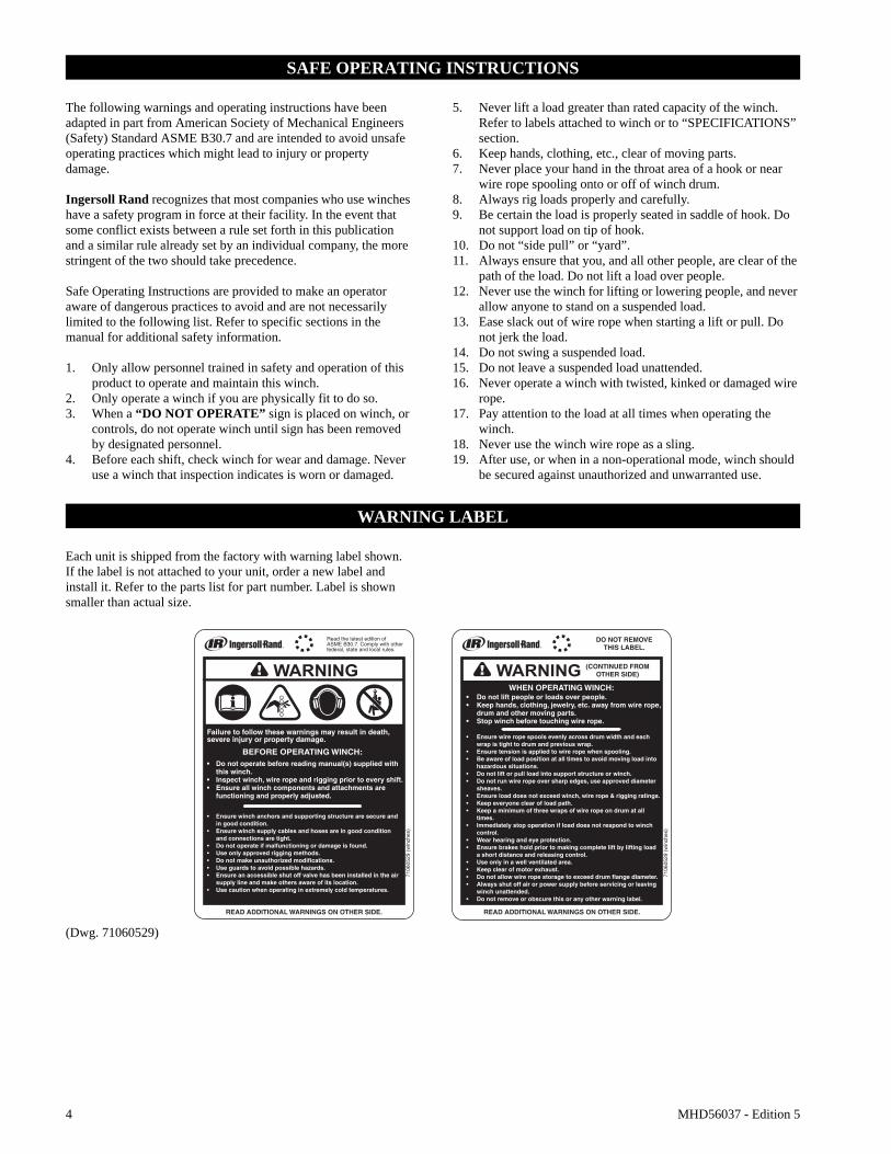
Each unit is shipped from the factory with warning label shown. If the label is not attached to your unit, order a new label and install it. Refer to the parts list for part number. Label is shown smaller than actual size.
(Dwg. 71060529)
MHD56037 - Edition 5 5
SPECIFICATIONS
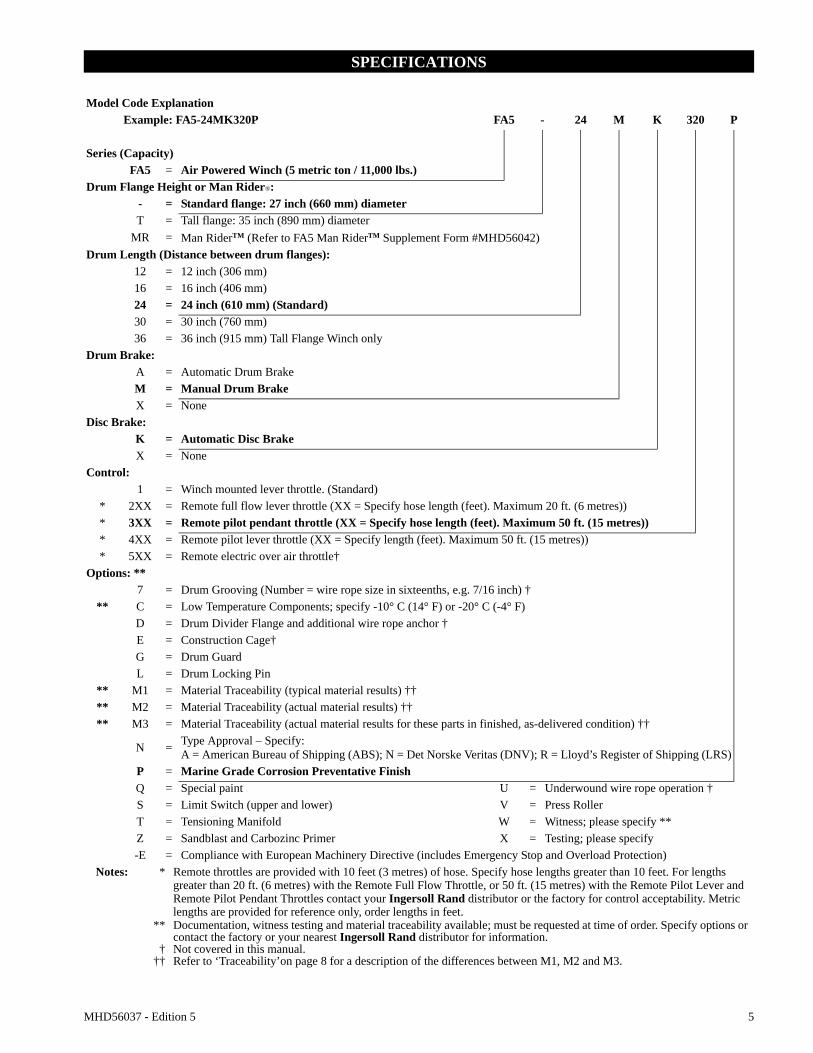
Model Code ExplanationExample: FA5-24MK320P FA5 - 24 M K 320 P
Series (Capacity)FA5 = Air Powered Winch (5 metric ton / 11,000 lbs.)
Drum Flange Height or Man Rider®:- = Standard flange: 27 inch (660 mm) diameterT = Tall flange: 35 inch (890 mm) diameter
MR = Man RiderTM (Refer to FA5 Man RiderTM Supplement Form #MHD56042)Drum Length (Distance between drum flanges):
12 = 12 inch (306 mm)16 = 16 inch (406 mm)24 = 24 inch (610 mm) (Standard)30 = 30 inch (760 mm)36 = 36 inch (915 mm) Tall Flange Winch only
Control:1 = Winch mounted lever throttle. (Standard)
* 2XX = Remote full flow lever throttle (XX = Specify hose length (feet). Maximum 20 ft. (6 metres))* 3XX = Remote pilot pendant throttle (XX = Specify hose length (feet). Maximum 50 ft. (15 metres))* 4XX = Remote pilot lever throttle (XX = Specify length (feet). Maximum 50 ft. (15 metres))* 5XX = Remote electric over air throttle†
Options: **7 = Drum Grooving (Number = wire rope size in sixteenths, e.g. 7/16 inch) †
** C = Low Temperature Components; specify -10° C (14° F) or -20° C (-4° F)D = Drum Divider Flange and additional wire rope anchor †E = Construction Cage†G = Drum GuardL = Drum Locking Pin
** M1 = Material Traceability (typical material results) ††** M2 = Material Traceability (actual material results) ††** M3 = Material Traceability (actual material results for these parts in finished, as-delivered condition) ††
N = Type Approval – Specify:A = American Bureau of Shipping (ABS); N = Det Norske Veritas (DNV); R = Lloyd’s Register of Shipping (LRS)
P = Marine Grade Corrosion Preventative FinishQ = Special paint U = Underwound wire rope operation †S = Limit Switch (upper and lower) V = Press RollerT = Tensioning Manifold W = Witness; please specify **Z = Sandblast and Carbozinc Primer X = Testing; please specify-E = Compliance with European Machinery Directive (includes Emergency Stop and Overload Protection)
Notes: * Remote throttles are provided with 10 feet (3 metres) of hose. Specify hose lengths greater than 10 feet. For lengths greater than 20 ft. (6 metres) with the Remote Full Flow Throttle, or 50 ft. (15 metres) with the Remote Pilot Lever and Remote Pilot Pendant Throttles contact your Ingersoll Rand distributor or the factory for control acceptability. Metric lengths are provided for reference only, order lengths in feet.
** Documentation, witness testing and material traceability available; must be requested at time of order. Specify options or contact the factory or your nearest Ingersoll Rand distributor for information.
† Not covered in this manual.†† Refer to ‘Traceability’on page 8 for a description of the differences between M1, M2 and M3.
6 MHD56037 - Edition 5
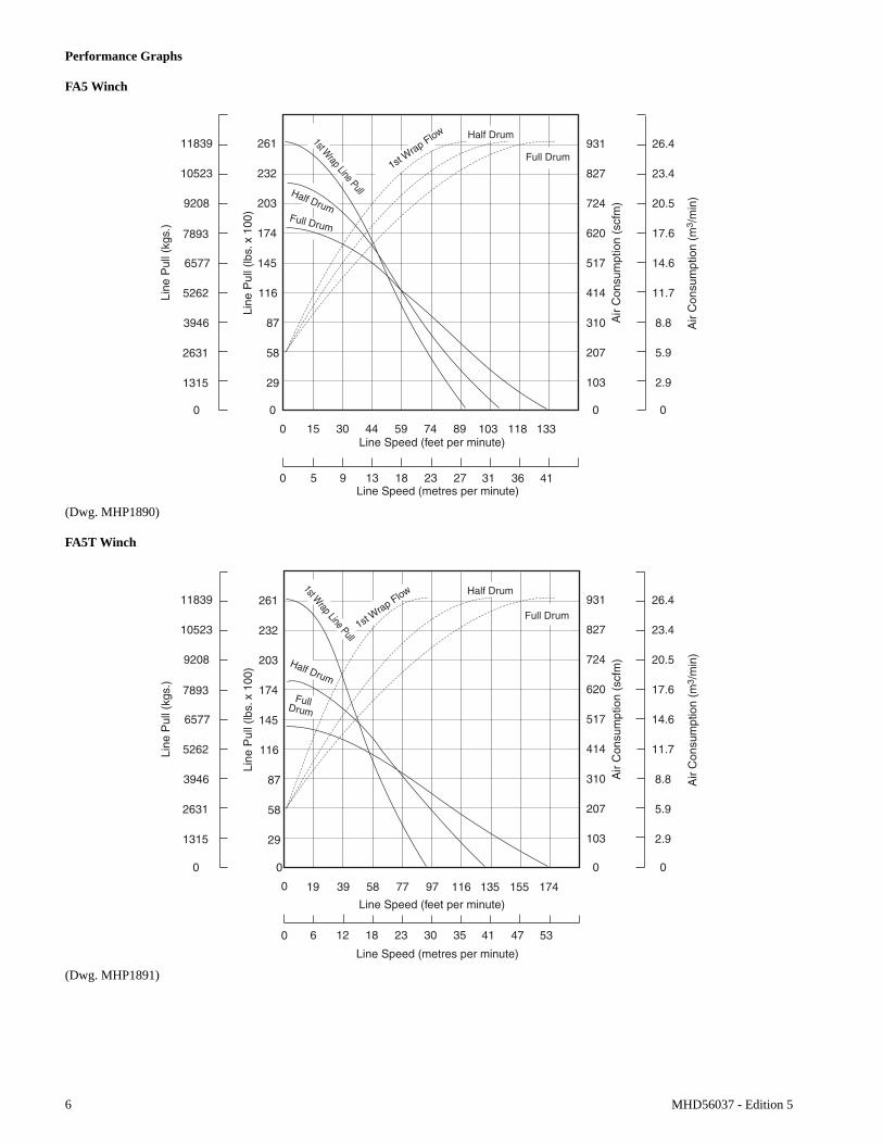
Performance Graphs
FA5 Winch
(Dwg. MHP1890)
FA5T Winch
(Dwg. MHP1891)
MHD56037 - Edition 5 7
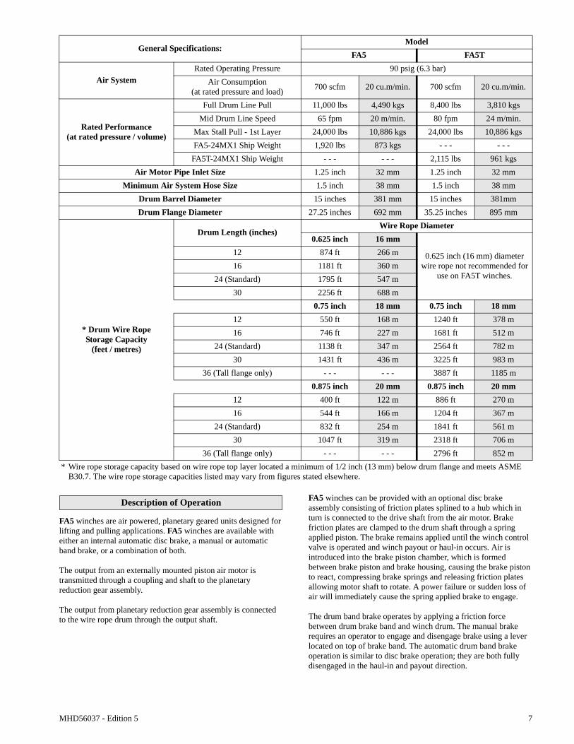
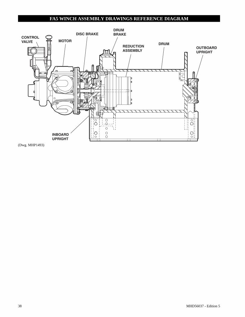
Description of Operation
FA5 winches are air powered, planetary geared units designed for lifting and pulling applications. FA5 winches are available with either an internal automatic disc brake, a manual or automatic band brake, or a combination of both.
The output from an externally mounted piston air motor is transmitted through a coupling and shaft to the planetary reduction gear assembly.
The output from planetary reduction gear assembly is connected to the wire rope drum through the output shaft.
FA5 winches can be provided with an optional disc brake assembly consisting of friction plates splined to a hub which in turn is connected to the drive shaft from the air motor. Brake friction plates are clamped to the drum shaft through a spring applied piston. The brake remains applied until the winch control valve is operated and winch payout or haul-in occurs. Air is introduced into the brake piston chamber, which is formed between brake piston and brake housing, causing the brake piston to react, compressing brake springs and releasing friction plates allowing motor shaft to rotate. A power failure or sudden loss of air will immediately cause the spring applied brake to engage.
The drum band brake operates by applying a friction force between drum brake band and winch drum. The manual brake requires an operator to engage and disengage brake using a lever located on top of brake band. The automatic drum band brake operation is similar to disc brake operation; they are both fully disengaged in the haul-in and payout direction.
General Specifications:Model
FA5 FA5T
Air System Rated Operating Pressure 90 psig (6.3 bar)
Air Consumption(at rated pressure and load) 700 scfm 20 cu.m/min. 700 scfm 20 cu.m/min.
Rated Performance(at rated pressure / volume)
Full Drum Line Pull 11,000 lbs 4,490 kgs 8,400 lbs 3,810 kgsMid Drum Line Speed 65 fpm 20 m/min. 80 fpm 24 m/min.
FA5T-24MX1 Ship Weight - - - - - - 2,115 lbs 961 kgsAir Motor Pipe Inlet Size 1.25 inch 32 mm 1.25 inch 32 mm
Minimum Air System Hose Size 1.5 inch 38 mm 1.5 inch 38 mmDrum Barrel Diameter 15 inches 381 mm 15 inches 381mmDrum Flange Diameter 27.25 inches 692 mm 35.25 inches 895 mm
* Drum Wire RopeStorage Capacity
(feet / metres)
Drum Length (inches)Wire Rope Diameter
0.625 inch 16 mm
0.625 inch (16 mm) diameter wire rope not recommended for
use on FA5T winches.
12 874 ft 266 m16 1181 ft 360 m
24 (Standard) 1795 ft 547 m30 2256 ft 688 m
0.75 inch 18 mm 0.75 inch 18 mm12 550 ft 168 m 1240 ft 378 m16 746 ft 227 m 1681 ft 512 m
24 (Standard) 1138 ft 347 m 2564 ft 782 m30 1431 ft 436 m 3225 ft 983 m
36 (Tall flange only) - - - - - - 3887 ft 1185 m0.875 inch 20 mm 0.875 inch 20 mm
12 400 ft 122 m 886 ft 270 m16 544 ft 166 m 1204 ft 367 m
24 (Standard) 832 ft 254 m 1841 ft 561 m30 1047 ft 319 m 2318 ft 706 m
36 (Tall flange only) - - - - - - 2796 ft 852 m* Wire rope storage capacity based on wire rope top layer located a minimum of 1/2 inch (13 mm) below drum flange and meets ASME
B30.7. The wire rope storage capacities listed may vary from figures stated elsewhere.
8 MHD56037 - Edition 5
Traceability
Load bearing parts are documented to provide traceability. The documentation includes chemical and physical properties of raw material, heat treating, hardening, tensile and charpy tests as required for the part.
Units with M1, M2 or M3 in the model code have traceable load bearing components.
M1–Material Traceability certificates according to EN 10204 (Ex DIN 50049) 2.2 on load bearing parts. Conformity documents affirm (by manufacturer) that parts are in compliance with requirements of order based on non-specific inspection and testing (i.e. results are typical material properties for these parts).
M2–Material Traceability certificates according to EN 10204 (Ex DIN 50049) 3.1b on load bearing parts. Conformity documents affirm (by a department independent of the manufacturing department) that the actual parts are in compliance with the requirements of the order based on specific inspection and testing (i.e. results are actual material properties for these parts).
M3–Material Traceability certificates according to EN 10204 (Ex DIN 50049) 3.1b on load bearing parts. Conformity documents affirm (by a department independent of the manufacturing department) that the actual parts used in the product are in compliance with the order based on specific inspection and testing (i.e. results are actual material properties for these parts in a finished, as delivered condition).
Components with part numbers ending in CH or CHA are charpy parts for use under extreme cold conditions. Traceability requirements must be stated when reordering these parts for continued certification.
INSTALLATION
Prior to installing winch, carefully inspect it for possible shipping damage.Winches are supplied fully lubricated from the factory. Before operation check oil levels and adjust as necessary. Use the proper type of oil as recommended in “LUBRICATION” section.
CAUTION
• Owners and users are advised to examine specific, local or other regulations, including American Society of Mechanical Engineers Standards and/or OSHA Regulations which may apply to a particular type of use of this product before installing or putting winch to use.
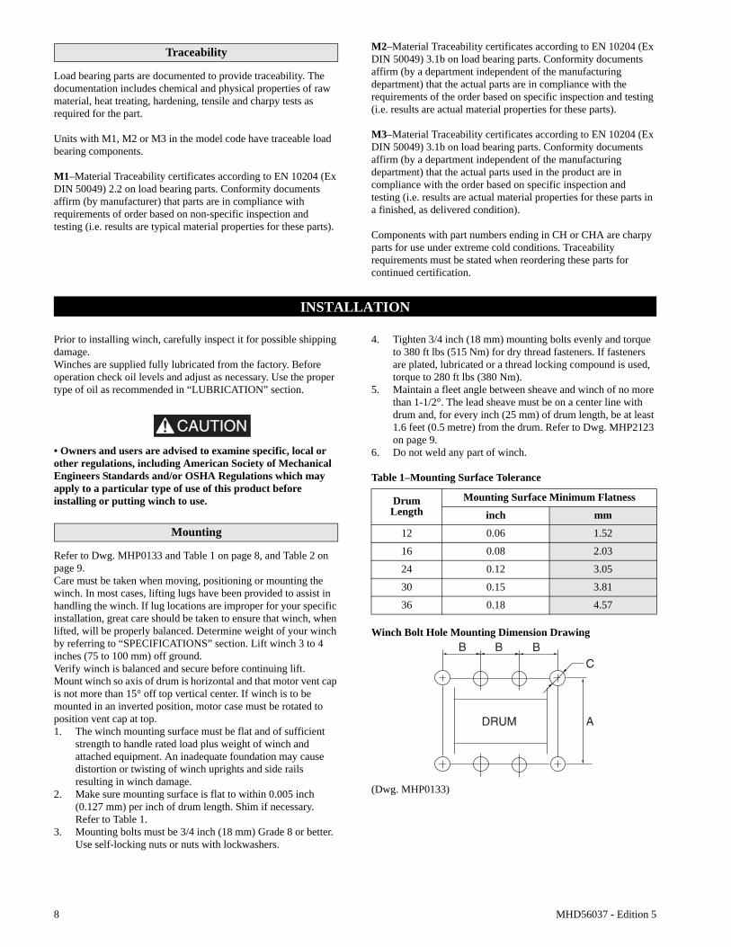
Mounting
Refer to Dwg. MHP0133 and Table 1 on page 8, and Table 2 on page 9.Care must be taken when moving, positioning or mounting the winch. In most cases, lifting lugs have been provided to assist in handling the winch. If lug locations are improper for your specific installation, great care should be taken to ensure that winch, when lifted, will be properly balanced. Determine weight of your winch by referring to “SPECIFICATIONS” section. Lift winch 3 to 4 inches (75 to 100 mm) off ground.Verify winch is balanced and secure before continuing lift.Mount winch so axis of drum is horizontal and that motor vent cap is not more than 15° off top vertical center. If winch is to be mounted in an inverted position, motor case must be rotated to position vent cap at top.1. The winch mounting surface must be flat and of sufficient
strength to handle rated load plus weight of winch and attached equipment. An inadequate foundation may cause distortion or twisting of winch uprights and side rails resulting in winch damage.
2. Make sure mounting surface is flat to within 0.005 inch (0.127 mm) per inch of drum length. Shim if necessary. Refer to Table 1.
3. Mounting bolts must be 3/4 inch (18 mm) Grade 8 or better. Use self-locking nuts or nuts with lockwashers.
4. Tighten 3/4 inch (18 mm) mounting bolts evenly and torque to 380 ft lbs (515 Nm) for dry thread fasteners. If fasteners are plated, lubricated or a thread locking compound is used, torque to 280 ft lbs (380 Nm).
5. Maintain a fleet angle between sheave and winch of no more than 1-1/2°. The lead sheave must be on a center line with drum and, for every inch (25 mm) of drum length, be at least 1.6 feet (0.5 metre) from the drum. Refer to Dwg. MHP2123 on page 9.
6. Do not weld any part of winch.
Table 1–Mounting Surface Tolerance
Winch Bolt Hole Mounting Dimension Drawing
(Dwg. MHP0133)
DrumLength
Mounting Surface Minimum Flatness
inch mm
12 0.06 1.52
16 0.08 2.03
24 0.12 3.05
30 0.15 3.81
36 0.18 4.57
MHD56037 - Edition 5 9
Table 2–Winch Bolt Hole Mounting Dimensions
(Dwg. MHP2123)
‘A’ = 1.6 feet (0.5 metre) per inch of drum length:‘A’ = 19.2 feet (5.85 metres) for 12 inch drum.‘A’ = 25.6 feet (7.80 metres) for 16 inch drum.‘A’ = 38.4 feet (11.7 metres) for 24 inch drum.‘A’ = 48.0 feet (14.6 metres) for 30 inch drum.‘A’ = 57.6 feet (17.5 metres) for 36 inch drum.
Notes:1. Maintain a minimum of 3 tight wraps of wire rope on drum at
all times.2. Ensure wire rope does not exceed top layer requirement.
Refer to “SPECIFICATIONS” section.
Wire Rope
CAUTION
• Maintain at least 3 tight wraps of wire rope on drum at all times.• Install wire rope to come off drum for overwind operation. (normal application.) Refer to Dwg. MHP2124 on page 9.
(Dwg. MHP2124)
NOTICE• For underwound applications order the “U” option or contact factory prior to operation.
Wire Rope Selection
Consult a reputable wire rope manufacturer or distributor for assistance in selecting appropriate type and size of wire rope and, where necessary, a protective coating. Use a wire rope which provides an adequate safety factor to handle actual working load and that meets all applicable industry, trade association, federal, state and local regulations.
When considering wire rope requirements the actual working load must include not only static or dead load but also loads resulting from acceleration, retardation and shock load. Consideration must also be given to the size of winch wire rope drum, sheaves and method of reeving. Wire rope construction should be 6 X 19 or 6 X 37 IWRC EIPS right regular lay. Refer to Table 3 on page 9 for minimum and maximum recommended wire rope sizes.
Table 3–Minimum and Maximum Wire Rope Size
DimensionDrum Length (inches)
12 16 24 30 36*
“A” FA5inch 31.25
- - -mm 794
“A” FA5Tinch 34.25
mm 870
“B” (with Drum Brake)
inch 7.5 9 10.5 10 11.5
mm 190 229 267 254 292
“B” (without Drum Brake)
inch 6 6.25 9 12 14
mm 152 159 229 305 356
“C”inch 13/16
mm 20
Bolt Hole Qty eachSide Rail 4 5
* 36 inch drum length applies to FA5T (tall flange) only.
ModelMinimum Maximum
inch mm inch mm
FA5 5/8 167/8 22
FA5T 3/4 20
Note: Maximum wire rope diameter is limited by size of wire rope anchor hole. Refer to parts list for correct wire rope anchor part numbers.
10 MHD56037 - Edition 5
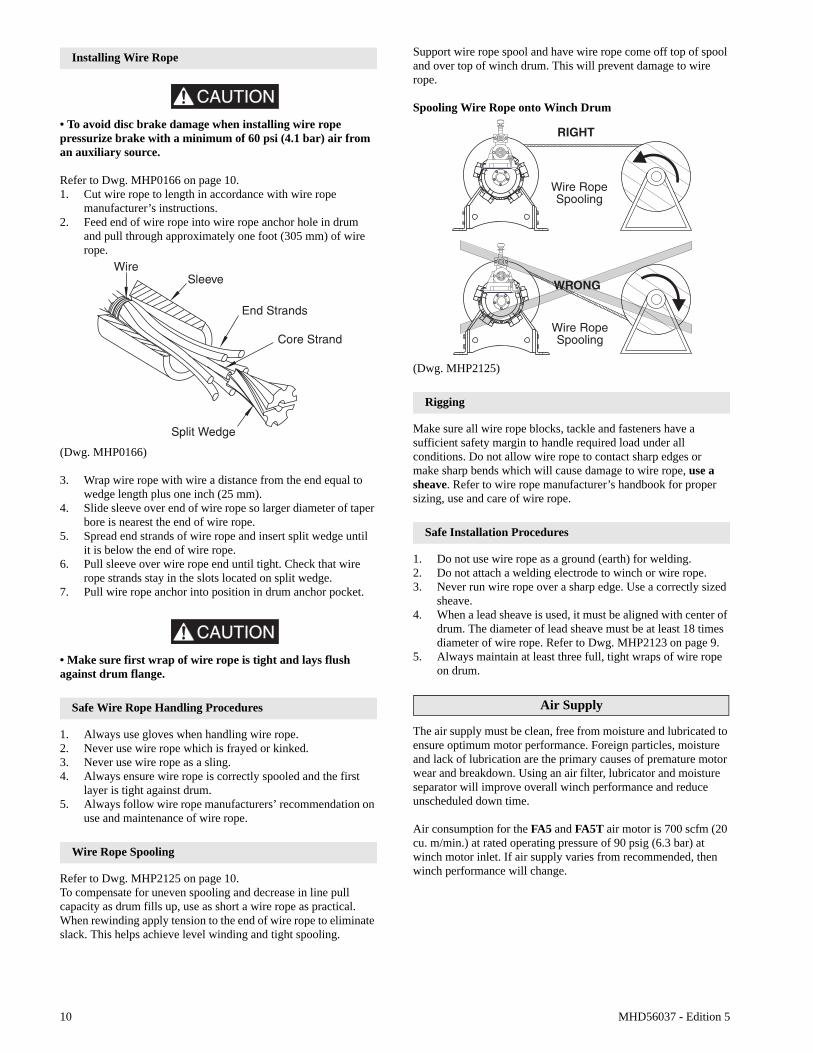
Installing Wire Rope
CAUTION
• To avoid disc brake damage when installing wire rope pressurize brake with a minimum of 60 psi (4.1 bar) air from an auxiliary source.
Refer to Dwg. MHP0166 on page 10.1. Cut wire rope to length in accordance with wire rope
manufacturer’s instructions.2. Feed end of wire rope into wire rope anchor hole in drum
and pull through approximately one foot (305 mm) of wire rope.
(Dwg. MHP0166)
3. Wrap wire rope with wire a distance from the end equal to wedge length plus one inch (25 mm).
4. Slide sleeve over end of wire rope so larger diameter of taper bore is nearest the end of wire rope.
5. Spread end strands of wire rope and insert split wedge until it is below the end of wire rope.
6. Pull sleeve over wire rope end until tight. Check that wire rope strands stay in the slots located on split wedge.
7. Pull wire rope anchor into position in drum anchor pocket.
CAUTION
• Make sure first wrap of wire rope is tight and lays flush against drum flange.
Safe Wire Rope Handling Procedures
1. Always use gloves when handling wire rope.2. Never use wire rope which is frayed or kinked.3. Never use wire rope as a sling.4. Always ensure wire rope is correctly spooled and the first
layer is tight against drum.5. Always follow wire rope manufacturers’ recommendation on
use and maintenance of wire rope.
Wire Rope Spooling
Refer to Dwg. MHP2125 on page 10.To compensate for uneven spooling and decrease in line pull capacity as drum fills up, use as short a wire rope as practical. When rewinding apply tension to the end of wire rope to eliminate slack. This helps achieve level winding and tight spooling.
Support wire rope spool and have wire rope come off top of spool and over top of winch drum. This will prevent damage to wire rope.
Spooling Wire Rope onto Winch Drum
(Dwg. MHP2125)
Rigging
Make sure all wire rope blocks, tackle and fasteners have a sufficient safety margin to handle required load under all conditions. Do not allow wire rope to contact sharp edges or make sharp bends which will cause damage to wire rope, use a sheave. Refer to wire rope manufacturer’s handbook for proper sizing, use and care of wire rope.
Safe Installation Procedures
1. Do not use wire rope as a ground (earth) for welding.2. Do not attach a welding electrode to winch or wire rope.3. Never run wire rope over a sharp edge. Use a correctly sized
sheave.4. When a lead sheave is used, it must be aligned with center of
drum. The diameter of lead sheave must be at least 18 times diameter of wire rope. Refer to Dwg. MHP2123 on page 9.
5. Always maintain at least three full, tight wraps of wire rope on drum.
Air Supply
The air supply must be clean, free from moisture and lubricated to ensure optimum motor performance. Foreign particles, moisture and lack of lubrication are the primary causes of premature motor wear and breakdown. Using an air filter, lubricator and moisture separator will improve overall winch performance and reduce unscheduled down time.
Air consumption for the FA5 and FA5T air motor is 700 scfm (20 cu. m/min.) at rated operating pressure of 90 psig (6.3 bar) at winch motor inlet. If air supply varies from recommended, then winch performance will change.
MHD56037 - Edition 5 11
Air Lines
Inside diameter of winch air supply lines must not be less than sizes shown in Table 4 on page 11. Before making final connections, all air supply lines should be purged with clean, moisture free air or nitrogen before connecting to winch inlet. Supply lines should be as short and straight as installation conditions will permit. Long transmission lines and excessive use of fittings, elbows, tees, globe valves etc. cause a reduction in pressure due to restrictions and surface friction in lines.
Table 4–Minimum Allowable Air Supply Line Sizes
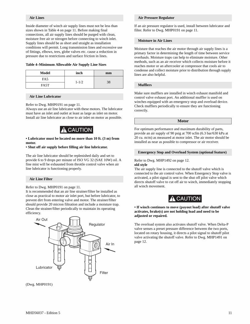
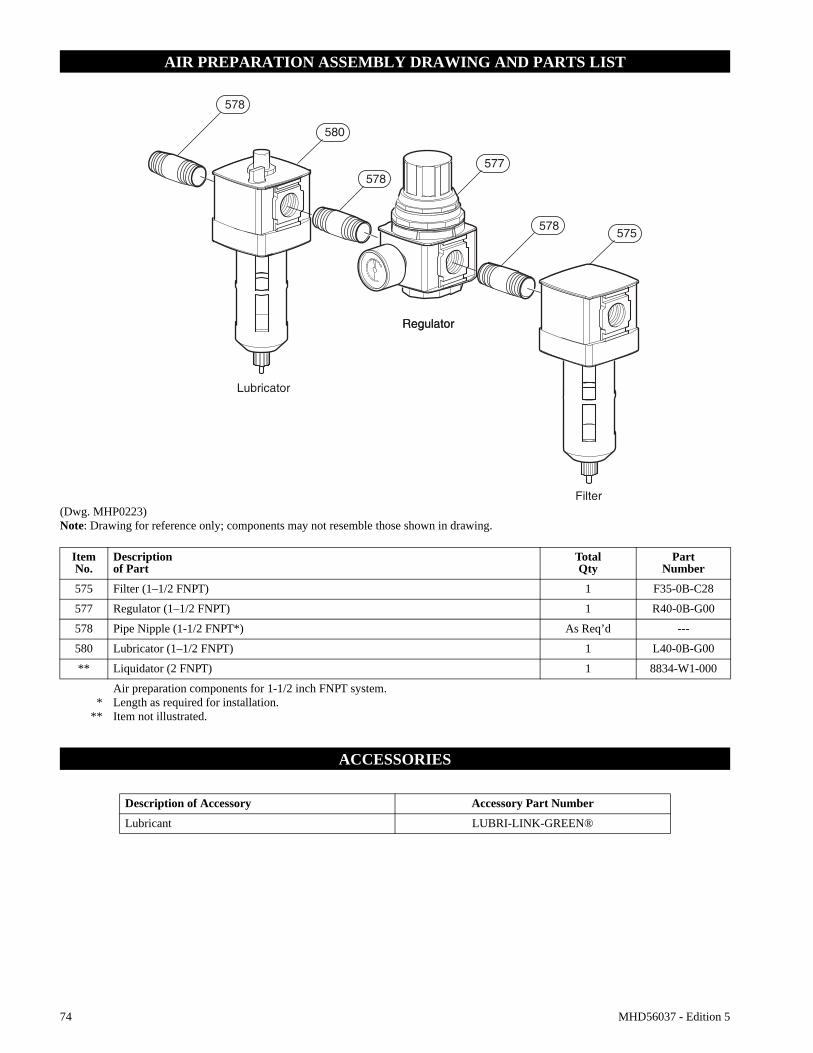
Air Line Lubricator
Refer to Dwg. MHP0191 on page 11.Always use an air line lubricator with these motors. The lubricator must have an inlet and outlet at least as large as inlet on motor. Install air line lubricator as close to air inlet on motor as possible.
CAUTION
• Lubricator must be located no more than 10 ft. (3 m) from motor.• Shut off air supply before filling air line lubricator.
The air line lubricator should be replenished daily and set to provide 6 to 9 drops per minute of ISO VG 32 (SAE 10W) oil. A fine mist will be exhausted from throttle control valve when air line lubricator is functioning properly.
Air Line Filter
Refer to Dwg. MHP0191 on page 11.It is recommended that an air line strainer/filter be installed as close as practical to motor air inlet port, but before lubricator, to prevent dirt from entering valve and motor. The strainer/filter should provide 20 micron filtration and include a moisture trap. Clean the strainer/filter periodically to maintain its operating efficiency.
(Dwg. MHP0191)
Air Pressure Regulator
If an air pressure regulator is used, install between lubricator and filter. Refer to Dwg. MHP0191 on page 11.
Moisture in Air Lines
Moisture that reaches the air motor through air supply lines is a primary factor in determining the length of time between service overhauls. Moisture traps can help to eliminate moisture. Other methods, such as an air receiver which collects moisture before it reaches motor or an aftercooler at compressor that cools air to condense and collect moisture prior to distribution through supply lines are also helpful.
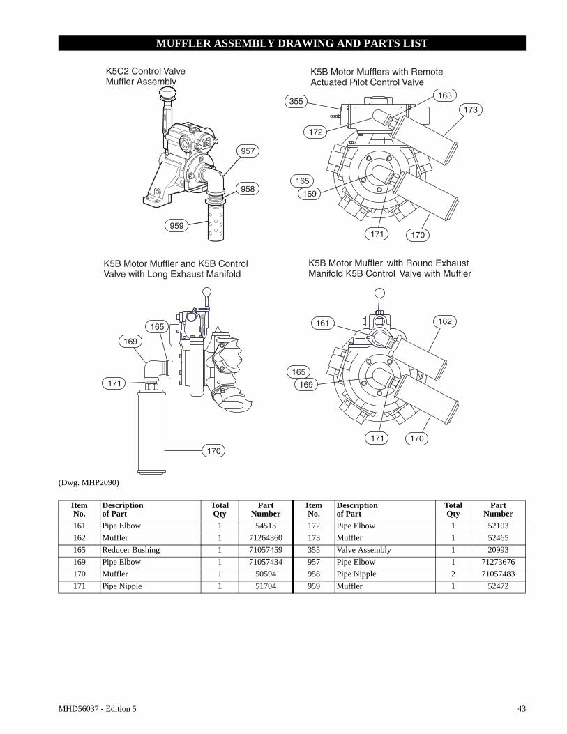
Mufflers
Make sure mufflers are installed in winch exhaust manifold and control valve exhaust port. An additional muffler is used on winches equipped with an emergency stop and overload device. Check mufflers periodically to ensure they are functioning correctly.
Motor
For optimum performance and maximum durability of parts, provide an air supply of 90 psig at 700 scfm (6.3 bar/630 kPa at 20 cu. m/m) as measured at motor inlet. The air motor should be installed as near as possible to compressor or air receiver.
Emergency Stop and Overload System (optional feature)
Refer to Dwg. MHP1492 on page 12.old styleThe air supply line is connected to the shutoff valve which is connected to the air control valve. When Emergency Stop valve is activated, a pilot signal is sent to the shut off pilot valve which directs shutoff valve to cut off air to winch, immediately stopping all winch movement.
CAUTION
• If winch continues to move (payout load) after shutoff valve activates, brake(s) are not holding load and need to be adjusted or repaired.
The overload system also activates shutoff valve. When Delta-P valve senses a preset pressure difference between the two ports, located on rotary housing, it directs a pilot signal to shutoff pilot valve activating the shutoff valve. Refer to Dwg. MHP1491 on page 12.
Model inch mm
FA51-1/2 38
FA5T
Air OutRegulator
Lubricator
Air In
Filter
12 MHD56037 - Edition 5
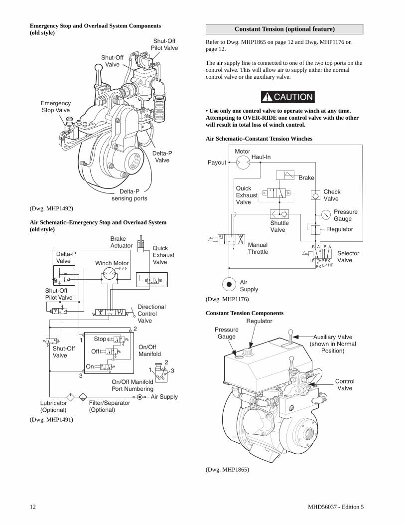
Emergency Stop and Overload System Components(old style)
(Dwg. MHP1492)
Air Schematic–Emergency Stop and Overload System(old style)
(Dwg. MHP1491)
Constant Tension (optional feature)
Refer to Dwg. MHP1865 on page 12 and Dwg. MHP1176 on page 12.
The air supply line is connected to one of the two top ports on the control valve. This will allow air to supply either the normal control valve or the auxiliary valve.
CAUTION
• Use only one control valve to operate winch at any time. Attempting to OVER-RIDE one control valve with the other will result in total loss of winch control.
Air Schematic–Constant Tension Winches
(Dwg. MHP1176)
Constant Tension Components
(Dwg. MHP1865)
MHD56037 - Edition 5 13
Initial Operating Checks
Winches are tested for proper operation prior to leaving factory. Before winch is placed into service the following initial operating checks should be performed. 1. When first running motor inject some light oil into inlet
connection to provide initial lubrication.2. When first operating winch it is recommended that motor be
operated slowly in both directions for a few minutes.
For winches that have been in storage the following start-up procedures are required.1. Give the winch an inspection conforming to requirements of
“Winches Not in Regular Use” in the “INSPECTION” section.
2. Pour a small amount of ISO VG 32 (SAE 10W) oil in motor inlet port.
3. Operate motor for 10 seconds in both directions to flush out any impurities.
4. The winch is now ready for normal use.
OPERATION
The four most important aspects of winch operation are:1. Follow all safety instructions when operating winch.2. Allow only people trained in safety and operation of this
winch to operate this equipment.3. Subject each winch to a regular inspection and maintenance
procedure.4. Be aware of winch capacity and weight of load at all times.
CAUTION
• To avoid damage to rigging, the structure supporting rigging and winch, do not “two-block” the end of wire rope.
* Two blocking occurs when winch wire rope is multi-reeved using two separate sheave blocks which are allowed to come into contact with each other during winch operation. When this occurs extreme forces are exerted on wire rope and sheave blocks which may result in equipment and or rigging failure.
Operators must be physically competent. Operators must have no health condition which might affect their ability to act, and they must have good hearing, vision and depth perception. The winch operator must be carefully instructed in his duties and must understand the operation of winch, including a study of the manufacturers’ literature. The operator must thoroughly understand proper methods of hitching loads and must have a good attitude regarding safety. It is the operator’s responsibility to refuse to operate winch under unsafe conditions.
WARNING• Winch is not designed or suitable for lifting, lowering or moving persons. Never lift loads over people.
Winch Controls
The spring loaded, motor mounted, live air manual throttle control valve is supplied as a standard feature on this winch. Optional remote throttle controls are available. Reference model code on the winch nameplate and compare it to the “SPECIFICATIONS” section, on page 5 of this manual, to determine your configuration. The throttle controls provide operator control of motor speed and direction of drum rotation.
Winch Mounted Air Throttle (standard feature)
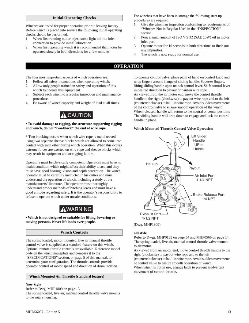
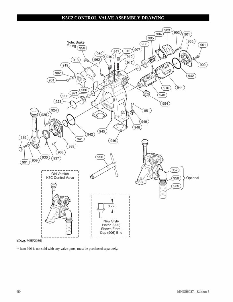
New StyleRefer to Dwg. MHP1809 on page 13.The spring loaded, live air, manual control throttle valve mounts to the rotary housing.
To operate control valve, place palm of hand on control knob and wrap fingers around flange of sliding handle. Squeeze fingers, lifting sliding handle up to unlock control lever. Shift control lever in desired direction to payout or haul-in wire rope.As viewed from the air motor end, move the control throttle handle to the right (clockwise) to payout wire rope and to the left (counterclockwise) to haul-in wire rope. Avoid sudden movements of the control valve to ensure smooth operation of the winch.When released, handle will return to the neutral or center position. The sliding handle will drop down to engage and lock the control handle in place.
Winch Mounted Throttle Control Valve Operation
(Dwg. MHP1809)
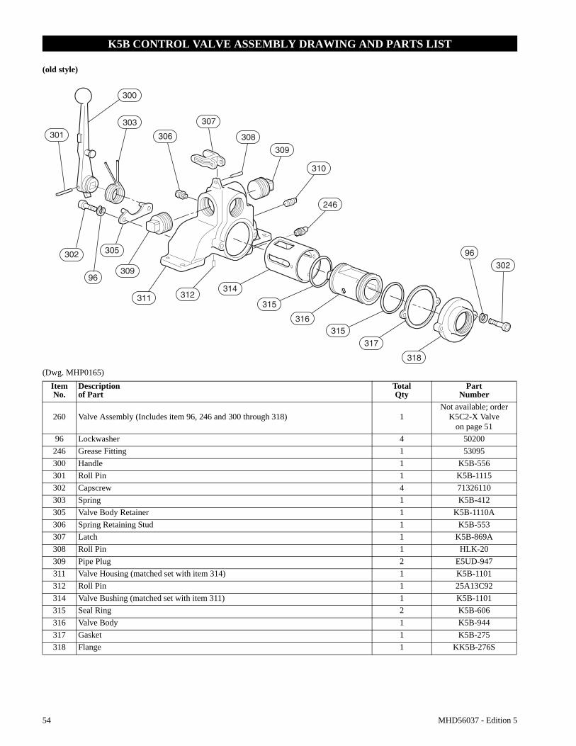
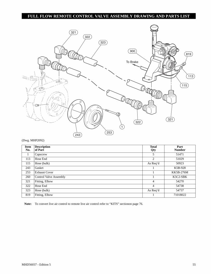
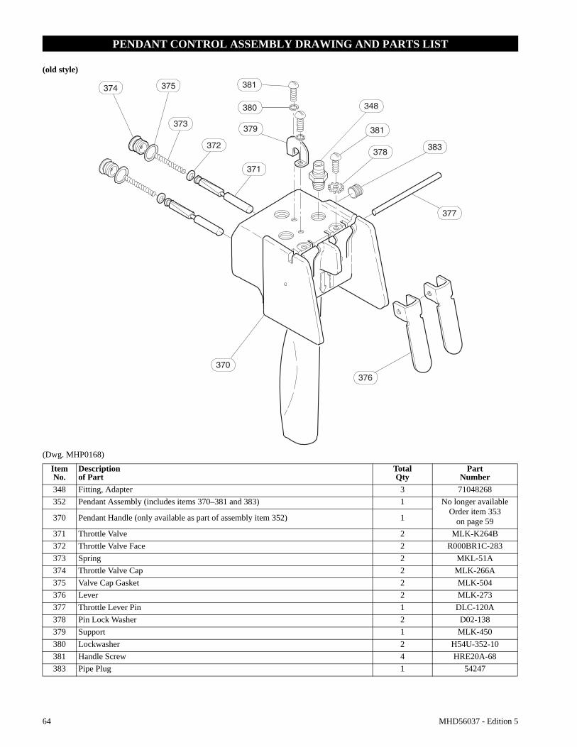
old styleRefer to Dwgs. MHP0165 on page 54 and MHP0566 on page 14.The spring loaded, live air, manual control throttle valve mounts to air motor.As viewed from air motor end, move control throttle handle to the right (clockwise) to payout wire rope and to the left (counterclockwise) to haul-in wire rope. Avoid sudden movements of control valve to ensure smooth operation of winch.When winch is not in use, engage latch to prevent inadvertent movement of control throttle.
Lift SliderHandleUP toUnlock
Exhaust Port1-1/2 NPT
Air Inlet Port1-1/4 NPT
Brake Release Port 1/4 NPT
PayoutHaul-In
14 MHD56037 - Edition 5
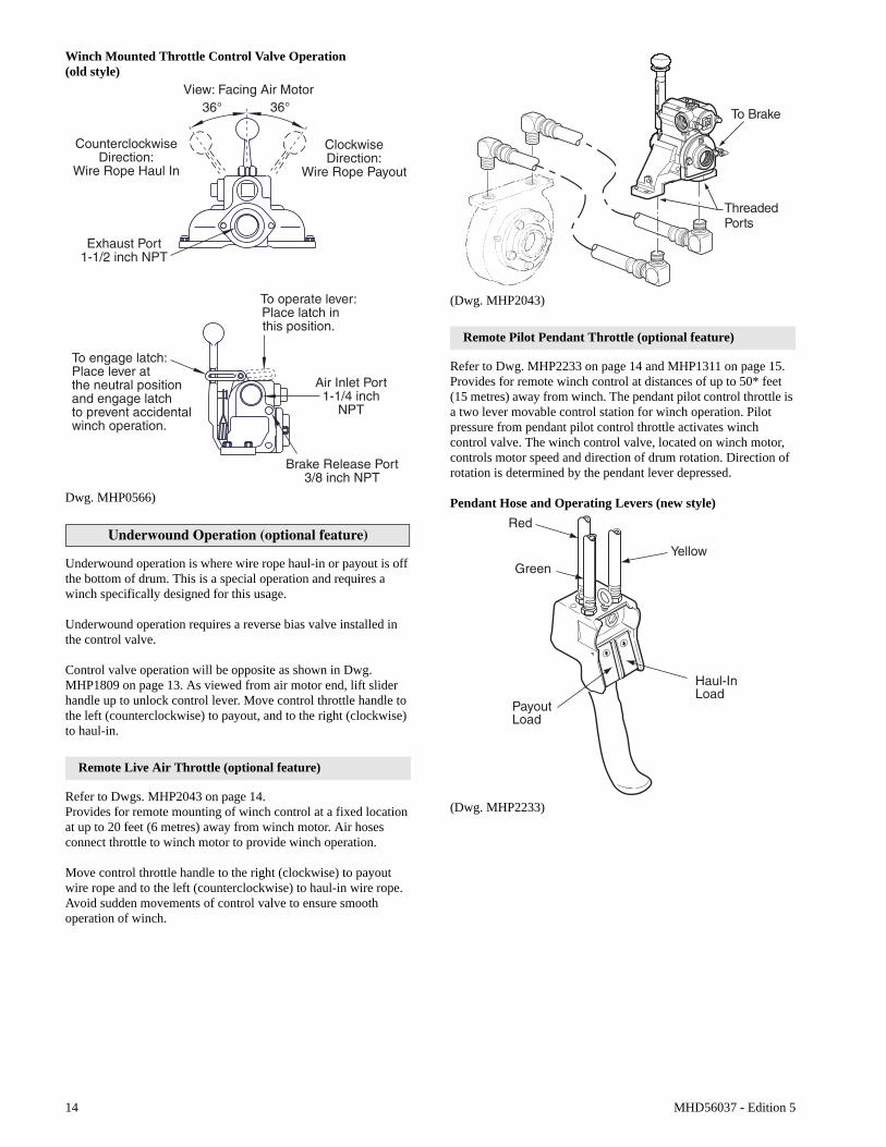
Winch Mounted Throttle Control Valve Operation (old style)
Dwg. MHP0566)
Underwound Operation (optional feature)
Underwound operation is where wire rope haul-in or payout is off the bottom of drum. This is a special operation and requires a winch specifically designed for this usage.
Underwound operation requires a reverse bias valve installed in the control valve.
Control valve operation will be opposite as shown in Dwg. MHP1809 on page 13. As viewed from air motor end, lift slider handle up to unlock control lever. Move control throttle handle to the left (counterclockwise) to payout, and to the right (clockwise) to haul-in.
Remote Live Air Throttle (optional feature)
Refer to Dwgs. MHP2043 on page 14.Provides for remote mounting of winch control at a fixed location at up to 20 feet (6 metres) away from winch motor. Air hoses connect throttle to winch motor to provide winch operation.
Move control throttle handle to the right (clockwise) to payout wire rope and to the left (counterclockwise) to haul-in wire rope. Avoid sudden movements of control valve to ensure smooth operation of winch.
(Dwg. MHP2043)
Remote Pilot Pendant Throttle (optional feature)
Refer to Dwg. MHP2233 on page 14 and MHP1311 on page 15.Provides for remote winch control at distances of up to 50* feet (15 metres) away from winch. The pendant pilot control throttle is a two lever movable control station for winch operation. Pilot pressure from pendant pilot control throttle activates winch control valve. The winch control valve, located on winch motor, controls motor speed and direction of drum rotation. Direction of rotation is determined by the pendant lever depressed.
Pendant Hose and Operating Levers (new style)
(Dwg. MHP2233)
PayoutLoad
Haul-InLoad
Red
GreenYellow
MHD56037 - Edition 5 15
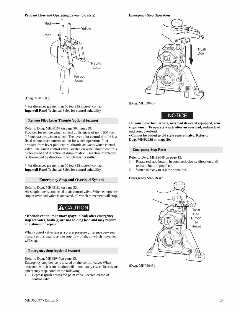
Pendant Hose and Operating Levers (old style)
(Dwg. MHP1311)
* For distances greater than 50 feet (15 metres) contact Ingersoll Rand Technical Sales for control suitability.
Remote Pilot Lever Throttle (optional feature)
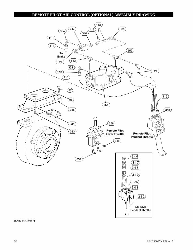
Refer to Dwg. MHP0167 on page 56, item 358.Provides for remote winch control at distances of up to 50* feet (15 metres) away from winch. The lever pilot control throttle is a fixed mount lever control station for winch operation. Pilot pressure from lever pilot control throttle activates winch control valve. The winch control valve, located on winch motor, controls motor speed and direction of drum rotation. Direction of rotation is determined by direction in which lever is shifted.
* For distances greater than 50 feet (15 metres) contact Ingersoll Rand Technical Sales for control suitability.
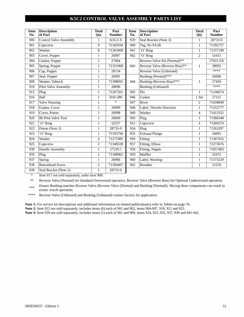
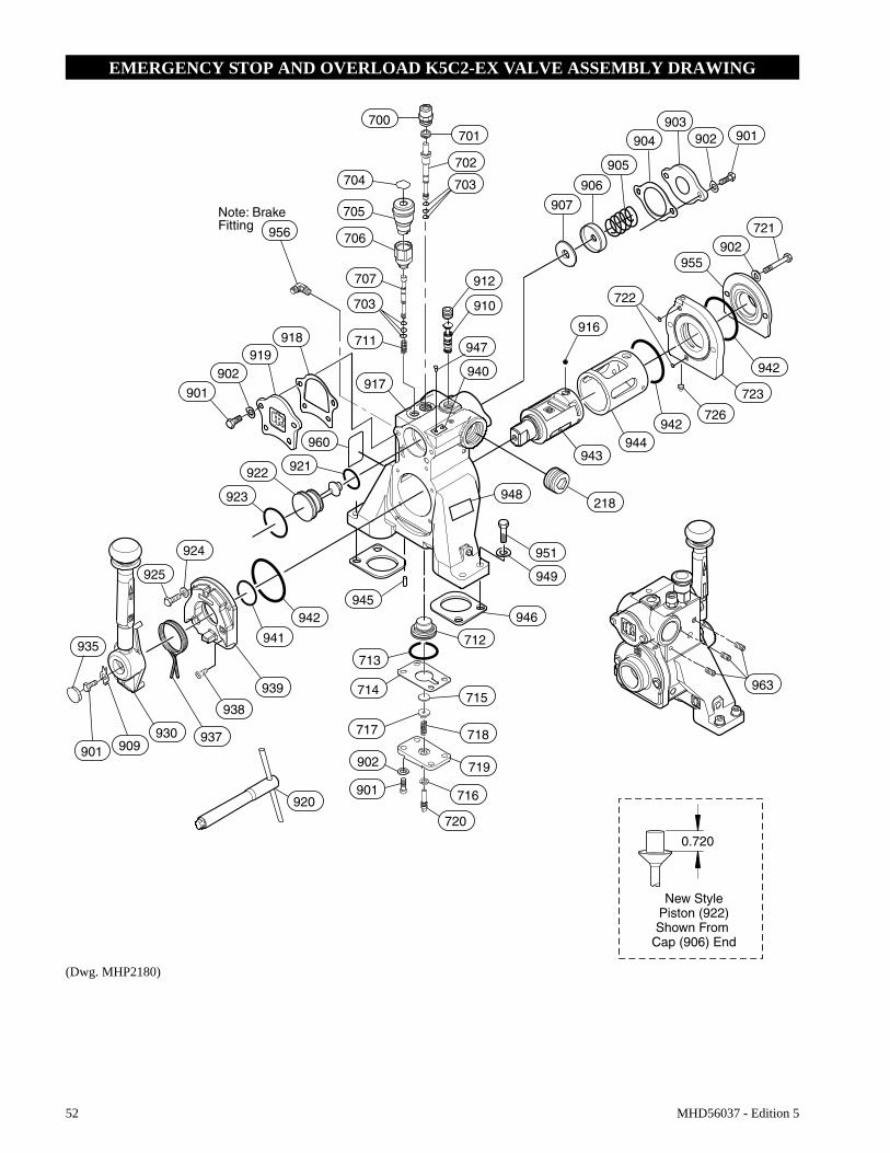
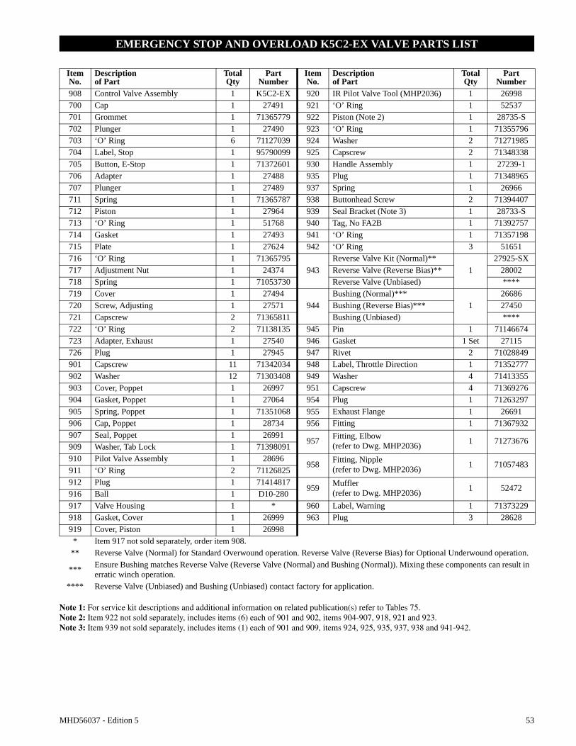
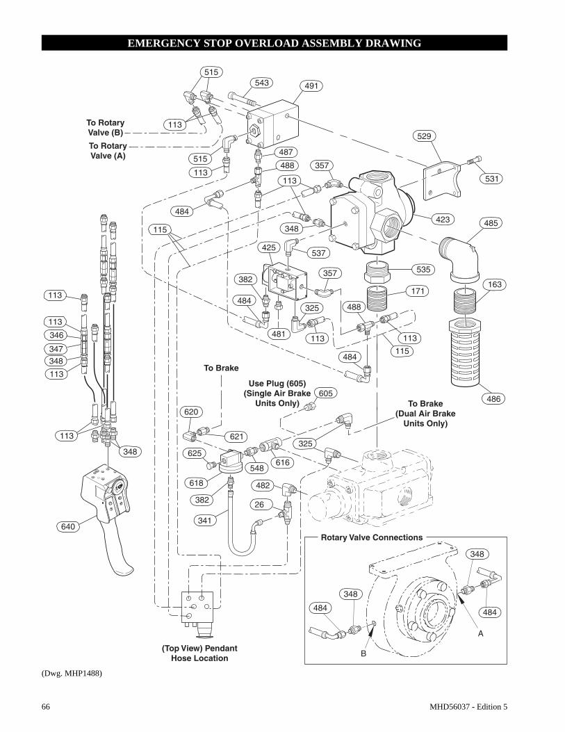
Emergency Stop and Overload System
Refer to Dwg. MHP2180 on page 52.Air supply line is connected to air control valve. When emergency stop or overload valve is activated, all winch movement will stop.
CAUTION
• If winch continues to move (payout load) after emergency stop activates, brake(s) are not holding load and may require adjustment or repair.
When control valve senses a preset pressure difference between ports, a pilot signal is sent to stop flow of air, all winch movement will stop.
Emergency Stop (optional feature)
Refer to Dwg. MHP2047on page 15.Emergency stop device is located on the control valve. When activated, winch drum rotation will immediately cease. To activate emergency stop, conduct the following:1. Depress (push down) red palm valve, located on top of
control valve.
Emergency Stop Operation
(Dwg. MHP2047)
NOTICE• If winch overload occurs, overload device, if equipped, also stops winch. To operate winch after an overload, reduce load and reset overload.• Cannot be added to old style control valve. Refer to Dwg. MHP2036 on page 50.
Emergency Stop Reset
Refer to Dwg. MHP2048 on page 15.1. Rotate red stop button, in counterclockwise direction until
red stop button ‘pops’ up.2. Winch is ready to resume operation.
Emergency Stop Reset
(Dwg. MHP2048)
16 MHD56037 - Edition 5
Overload Device
An overload device is available on winches with the emergency shutoff option. Overload device operation is based on differential pressure between air motor inlet and exhaust. The overload device is factory preset to actuate at 150% (± 25%) of winch rated capacity. When an overload condition is sensed, the valve poppet closes, to cut off supply air to winch, stopping winch operation. If an overload shutoff occurs, winch load must be reduced. Reset the overload valve and operate winch in payout direction to lower load. Refer to ‘Emergency Stop Reset’ section.
Checking Overload Valve Setting
1. Attach load line to a load that is calibrated to maximum load for which winch is rated.
2. Move control lever to haul-in position. If winch does not lift load, adjust the adjustment screw. Refer to ‘Overload Valve Adjustment’ section“Overload Valve Adjustment (optional feature)” on page 26.
Setting the Overload
Refer to MHP2049 on page 16 and MHP2216 on page 27.Attach load line to a load that is calibrated to 150% of winch rated capacity. Shift control lever to haul-in position.1. If overload valve activates, reset overload valve. Winch is
ready for normal operation.2. If winch lifts load, lower load. Turn adjustment screw
counterclockwise in 1/4 turn increments until overload valve activates when control lever is shifted to haul-in position. After each 1/4 turn, retest winch.
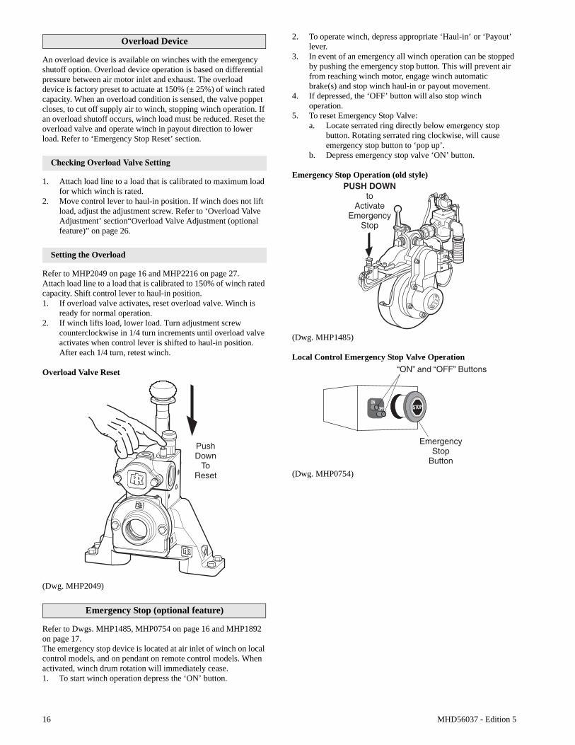
Overload Valve Reset
(Dwg. MHP2049)
Emergency Stop (optional feature)
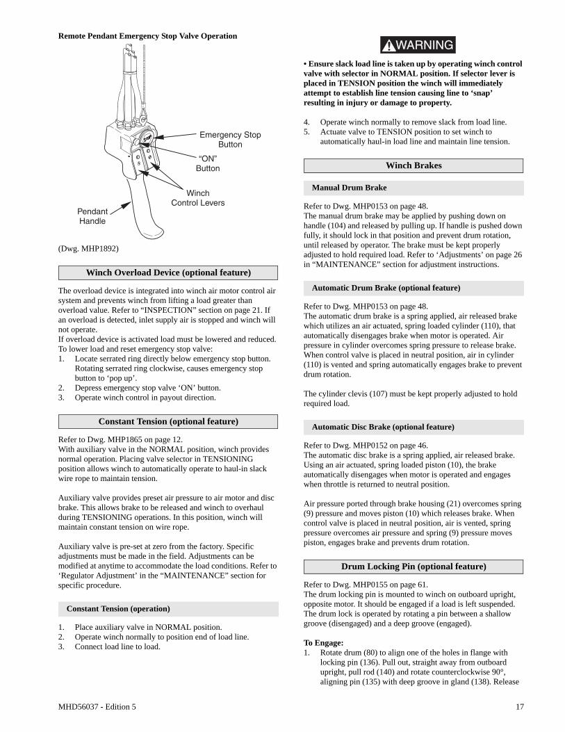
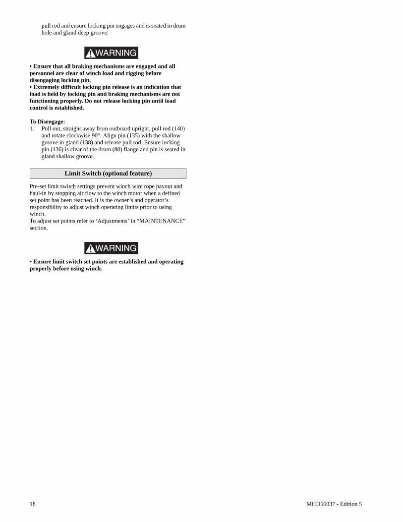
Refer to Dwgs. MHP1485, MHP0754 on page 16 and MHP1892 on page 17.The emergency stop device is located at air inlet of winch on local control models, and on pendant on remote control models. When activated, winch drum rotation will immediately cease.1. To start winch operation depress the ‘ON’ button.
2. To operate winch, depress appropriate ‘Haul-in’ or ‘Payout’ lever.
3. In event of an emergency all winch operation can be stopped by pushing the emergency stop button. This will prevent air from reaching winch motor, engage winch automatic brake(s) and stop winch haul-in or payout movement.
4. If depressed, the ‘OFF’ button will also stop winch operation.
5. To reset Emergency Stop Valve:a. Locate serrated ring directly below emergency stop
button. Rotating serrated ring clockwise, will cause emergency stop button to ‘pop up’.
b. Depress emergency stop valve ‘ON’ button.
Emergency Stop Operation (old style)
(Dwg. MHP1485)
Local Control Emergency Stop Valve Operation
(Dwg. MHP0754)
MHD56037 - Edition 5 17
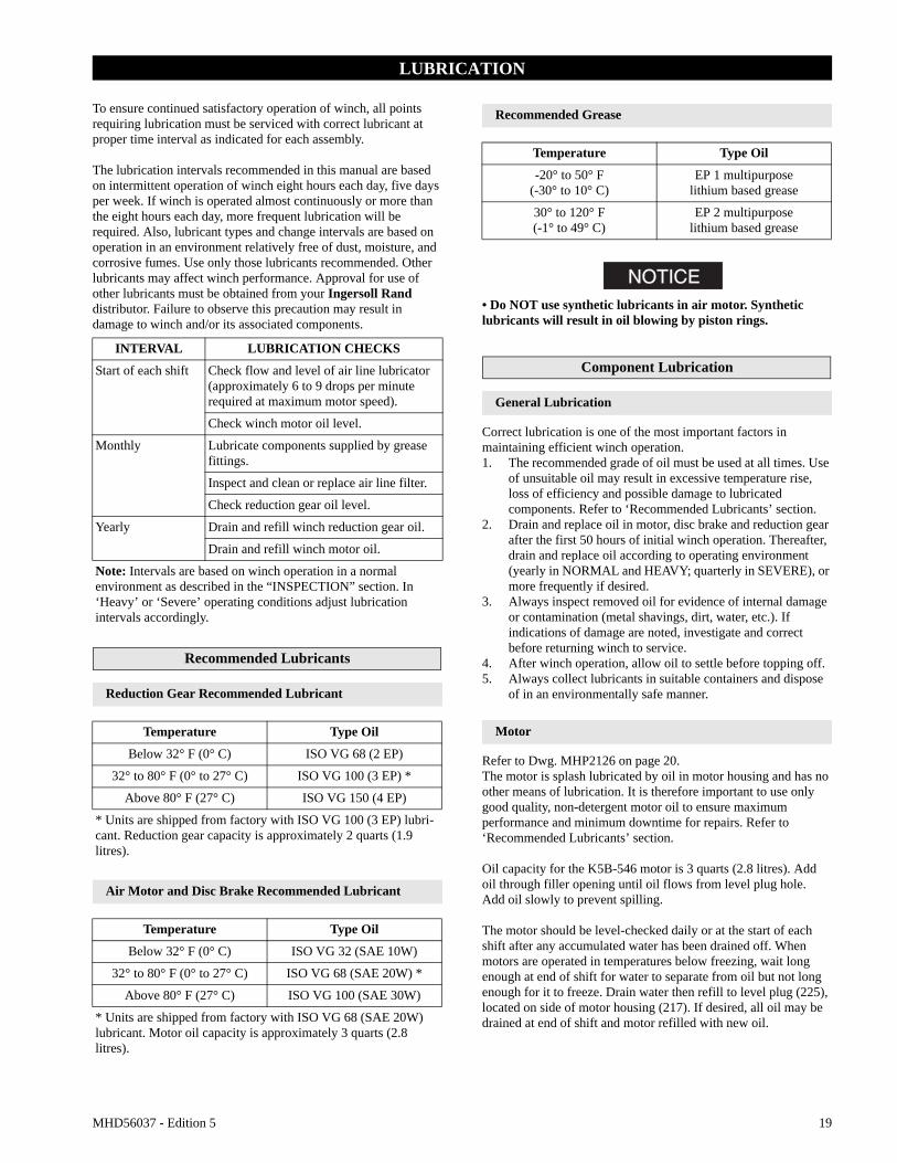
Remote Pendant Emergency Stop Valve Operation
(Dwg. MHP1892)
Winch Overload Device (optional feature)
The overload device is integrated into winch air motor control air system and prevents winch from lifting a load greater than overload value. Refer to “INSPECTION” section on page 21. If an overload is detected, inlet supply air is stopped and winch will not operate.If overload device is activated load must be lowered and reduced. To lower load and reset emergency stop valve:1. Locate serrated ring directly below emergency stop button.
Rotating serrated ring clockwise, causes emergency stop button to ‘pop up’.
2. Depress emergency stop valve ‘ON’ button.3. Operate winch control in payout direction.
Constant Tension (optional feature)
Refer to Dwg. MHP1865 on page 12.With auxiliary valve in the NORMAL position, winch provides normal operation. Placing valve selector in TENSIONING position allows winch to automatically operate to haul-in slack wire rope to maintain tension.
Auxiliary valve provides preset air pressure to air motor and disc brake. This allows brake to be released and winch to overhaul during TENSIONING operations. In this position, winch will maintain constant tension on wire rope.
Auxiliary valve is pre-set at zero from the factory. Specific adjustments must be made in the field. Adjustments can be modified at anytime to accommodate the load conditions. Refer to ‘Regulator Adjustment’ in the “MAINTENANCE” section for specific procedure.
Constant Tension (operation)
1. Place auxiliary valve in NORMAL position.2. Operate winch normally to position end of load line.3. Connect load line to load.
WARNING• Ensure slack load line is taken up by operating winch control valve with selector in NORMAL position. If selector lever is placed in TENSION position the winch will immediately attempt to establish line tension causing line to ‘snap’ resulting in injury or damage to property.
4. Operate winch normally to remove slack from load line.5. Actuate valve to TENSION position to set winch to
automatically haul-in load line and maintain line tension.
Winch Brakes
Manual Drum Brake
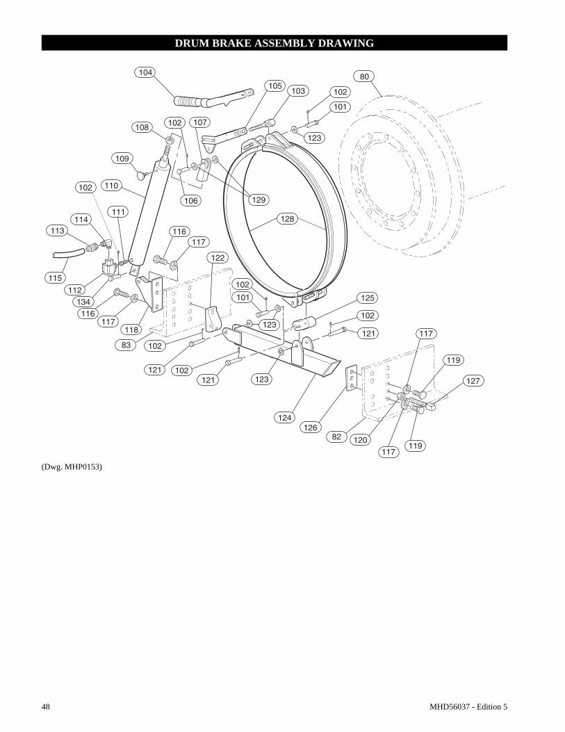
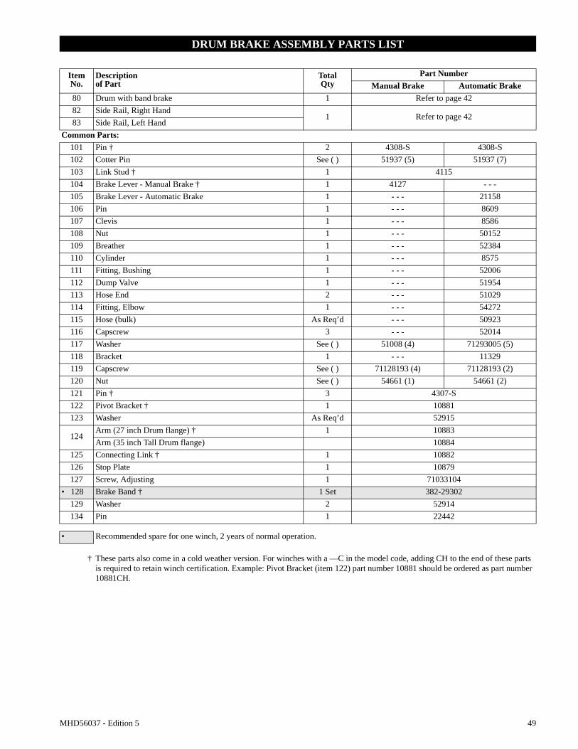
Refer to Dwg. MHP0153 on page 48.The manual drum brake may be applied by pushing down on handle (104) and released by pulling up. If handle is pushed down fully, it should lock in that position and prevent drum rotation, until released by operator. The brake must be kept properly adjusted to hold required load. Refer to ‘Adjustments’ on page 26 in “MAINTENANCE” section for adjustment instructions.
Automatic Drum Brake (optional feature)
Refer to Dwg. MHP0153 on page 48.The automatic drum brake is a spring applied, air released brake which utilizes an air actuated, spring loaded cylinder (110), that automatically disengages brake when motor is operated. Air pressure in cylinder overcomes spring pressure to release brake. When control valve is placed in neutral position, air in cylinder (110) is vented and spring automatically engages brake to prevent drum rotation.
The cylinder clevis (107) must be kept properly adjusted to hold required load.
Automatic Disc Brake (optional feature)
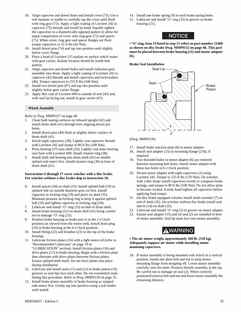
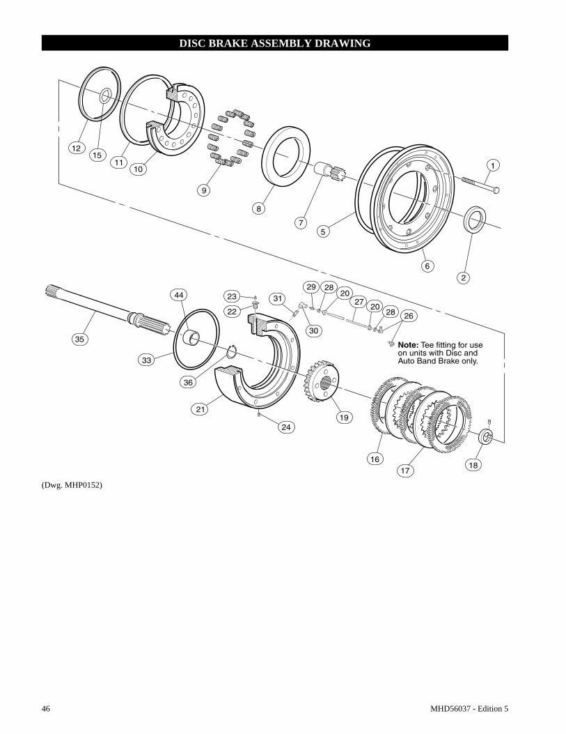
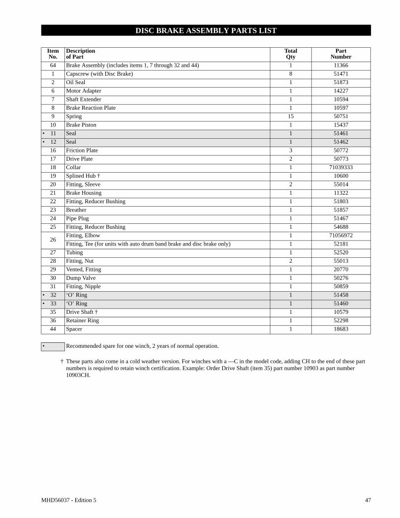
Refer to Dwg. MHP0152 on page 46.The automatic disc brake is a spring applied, air released brake. Using an air actuated, spring loaded piston (10), the brake automatically disengages when motor is operated and engages when throttle is returned to neutral position.
Air pressure ported through brake housing (21) overcomes spring (9) pressure and moves piston (10) which releases brake. When control valve is placed in neutral position, air is vented, spring pressure overcomes air pressure and spring (9) pressure moves piston, engages brake and prevents drum rotation.
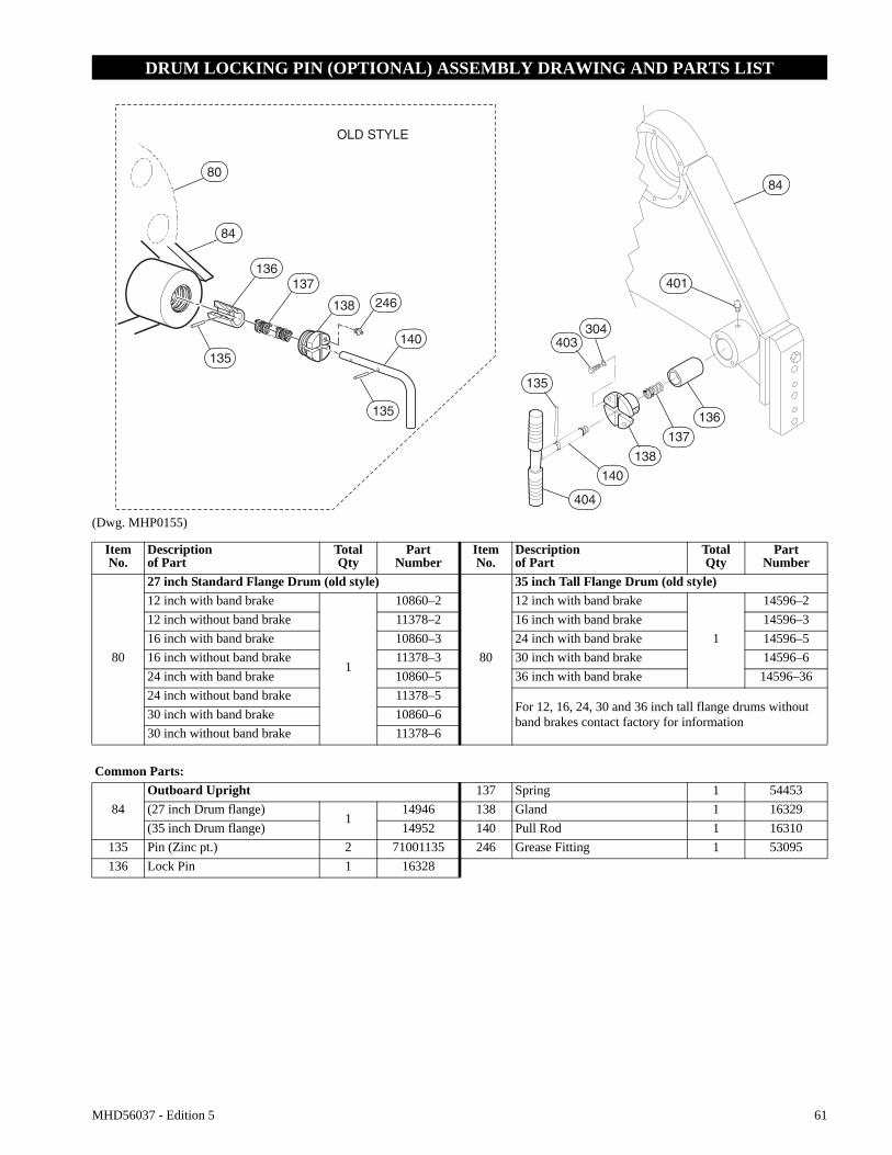
Drum Locking Pin (optional feature)
Refer to Dwg. MHP0155 on page 61.The drum locking pin is mounted to winch on outboard upright, opposite motor. It should be engaged if a load is left suspended. The drum lock is operated by rotating a pin between a shallow groove (disengaged) and a deep groove (engaged).
To Engage:1. Rotate drum (80) to align one of the holes in flange with
locking pin (136). Pull out, straight away from outboard upright, pull rod (140) and rotate counterclockwise 90°, aligning pin (135) with deep groove in gland (138). Release
18 MHD56037 - Edition 5
pull rod and ensure locking pin engages and is seated in drum hole and gland deep groove.
WARNING• Ensure that all braking mechanisms are engaged and all personnel are clear of winch load and rigging before disengaging locking pin.• Extremely difficult locking pin release is an indication that load is held by locking pin and braking mechanisms are not functioning properly. Do not release locking pin until load control is established.
To Disengage:1. Pull out, straight away from outboard upright, pull rod (140)
and rotate clockwise 90°. Align pin (135) with the shallow groove in gland (138) and release pull rod. Ensure locking pin (136) is clear of the drum (80) flange and pin is seated in gland shallow groove.
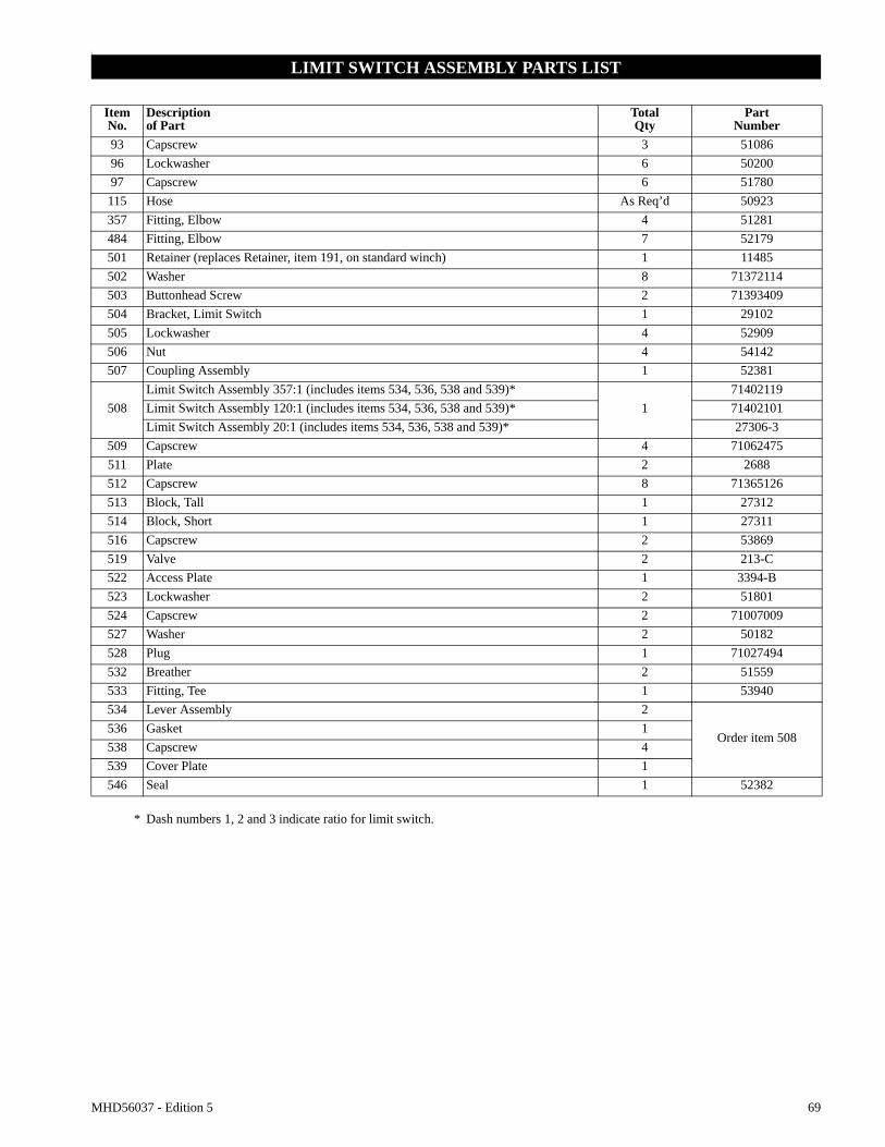
Limit Switch (optional feature)
Pre-set limit switch settings prevent winch wire rope payout and haul-in by stopping air flow to the winch motor when a defined set point has been reached. It is the owner’s and operator’s responsibility to adjust winch operating limits prior to using winch.To adjust set points refer to ‘Adjustments’ in “MAINTENANCE” section.
WARNING• Ensure limit switch set points are established and operating properly before using winch.
MHD56037 - Edition 5 19
LUBRICATION
To ensure continued satisfactory operation of winch, all points requiring lubrication must be serviced with correct lubricant at proper time interval as indicated for each assembly.
The lubrication intervals recommended in this manual are based on intermittent operation of winch eight hours each day, five days per week. If winch is operated almost continuously or more than the eight hours each day, more frequent lubrication will be required. Also, lubricant types and change intervals are based on operation in an environment relatively free of dust, moisture, and corrosive fumes. Use only those lubricants recommended. Other lubricants may affect winch performance. Approval for use of other lubricants must be obtained from your Ingersoll Rand distributor. Failure to observe this precaution may result in damage to winch and/or its associated components.
Recommended Lubricants
Reduction Gear Recommended Lubricant
Air Motor and Disc Brake Recommended Lubricant
Recommended Grease
NOTICE• Do NOT use synthetic lubricants in air motor. Synthetic lubricants will result in oil blowing by piston rings.
Component Lubrication
General Lubrication
Correct lubrication is one of the most important factors in maintaining efficient winch operation. 1. The recommended grade of oil must be used at all times. Use
of unsuitable oil may result in excessive temperature rise, loss of efficiency and possible damage to lubricated components. Refer to ‘Recommended Lubricants’ section.
2. Drain and replace oil in motor, disc brake and reduction gear after the first 50 hours of initial winch operation. Thereafter, drain and replace oil according to operating environment (yearly in NORMAL and HEAVY; quarterly in SEVERE), or more frequently if desired.
3. Always inspect removed oil for evidence of internal damage or contamination (metal shavings, dirt, water, etc.). If indications of damage are noted, investigate and correct before returning winch to service.
4. After winch operation, allow oil to settle before topping off.5. Always collect lubricants in suitable containers and dispose
of in an environmentally safe manner.
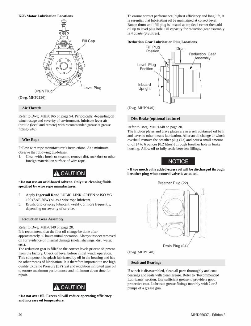
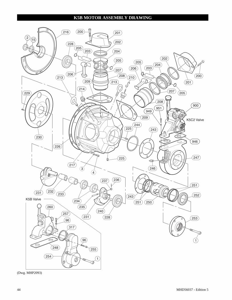
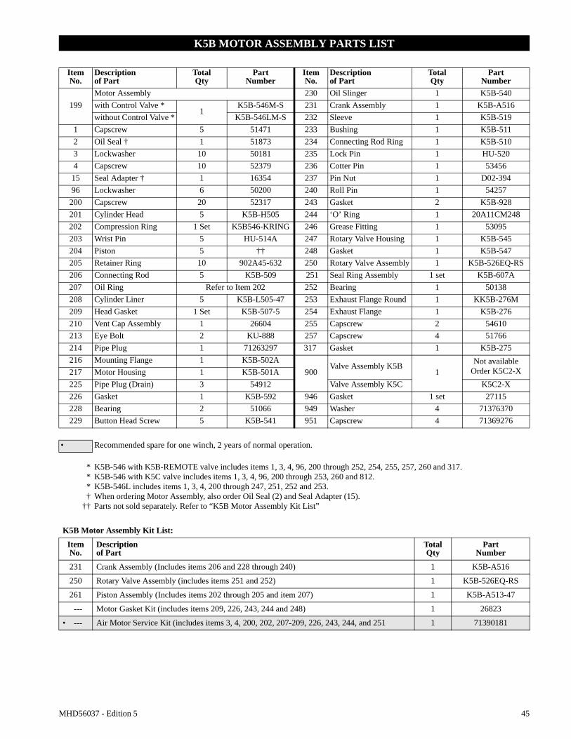
Motor
Refer to Dwg. MHP2126 on page 20.The motor is splash lubricated by oil in motor housing and has no other means of lubrication. It is therefore important to use only good quality, non-detergent motor oil to ensure maximum performance and minimum downtime for repairs. Refer to ‘Recommended Lubricants’ section.
Oil capacity for the K5B-546 motor is 3 quarts (2.8 litres). Add oil through filler opening until oil flows from level plug hole. Add oil slowly to prevent spilling.
The motor should be level-checked daily or at the start of each shift after any accumulated water has been drained off. When motors are operated in temperatures below freezing, wait long enough at end of shift for water to separate from oil but not long enough for it to freeze. Drain water then refill to level plug (225), located on side of motor housing (217). If desired, all oil may be drained at end of shift and motor refilled with new oil.
INTERVAL LUBRICATION CHECKS
Start of each shift Check flow and level of air line lubricator (approximately 6 to 9 drops per minute required at maximum motor speed).
Check winch motor oil level.
Monthly Lubricate components supplied by grease fittings.
Inspect and clean or replace air line filter.
Check reduction gear oil level.
Yearly Drain and refill winch reduction gear oil.
Drain and refill winch motor oil.
Note: Intervals are based on winch operation in a normal environment as described in the “INSPECTION” section. In ‘Heavy’ or ‘Severe’ operating conditions adjust lubrication intervals accordingly.
Temperature Type Oil
Below 32° F (0° C) ISO VG 68 (2 EP)
32° to 80° F (0° to 27° C) ISO VG 100 (3 EP) *
Above 80° F (27° C) ISO VG 150 (4 EP)
* Units are shipped from factory with ISO VG 100 (3 EP) lubri-cant. Reduction gear capacity is approximately 2 quarts (1.9 litres).
Temperature Type Oil
Below 32° F (0° C) ISO VG 32 (SAE 10W)
32° to 80° F (0° to 27° C) ISO VG 68 (SAE 20W) *
Above 80° F (27° C) ISO VG 100 (SAE 30W)
* Units are shipped from factory with ISO VG 68 (SAE 20W) lubricant. Motor oil capacity is approximately 3 quarts (2.8 litres).
Temperature Type Oil
-20° to 50° F(-30° to 10° C)
EP 1 multipurposelithium based grease
30° to 120° F(-1° to 49° C)
EP 2 multipurposelithium based grease
20 MHD56037 - Edition 5
K5B Motor Lubrication Locations
(Dwg. MHP2126)
Air Throttle
Refer to Dwg. MHP0165 on page 54. Periodically, depending on winch usage and severity of environment, lubricate lever air throttle (local and remote) with recommended grease at grease fitting (246).
Wire Rope
Follow wire rope manufacturer’s instructions. At a minimum, observe the following guidelines.1. Clean with a brush or steam to remove dirt, rock dust or other
foreign material on surface of wire rope.
CAUTION
• Do not use an acid-based solvent. Only use cleaning fluids specified by wire rope manufacturer.
2. Apply Ingersoll Rand LUBRI-LINK-GREEN or ISO VG 100 (SAE 30W) oil as a wire rope lubricant.
3. Brush, drip or spray lubricant weekly, or more frequently, depending on severity of service.
Reduction Gear Assembly
Refer to Dwg. MHP0140 on page 20.It is recommend that the first oil change be done after approximately 50 hours initial operation. Always inspect removed oil for evidence of internal damage (metal shavings, dirt, water, etc.).The reduction gear is filled to the correct levels prior to shipment from the factory. Check oil level before initial winch operation. This component is splash lubricated by oil in the housing and has no other means of lubrication. It is therefore important to use high quality Extreme Pressure (EP) rust and oxidation inhibited gear oil to ensure maximum performance and minimum down time for repair.
CAUTION
• Do not over fill. Excess oil will reduce operating efficiency and increase oil temperature.
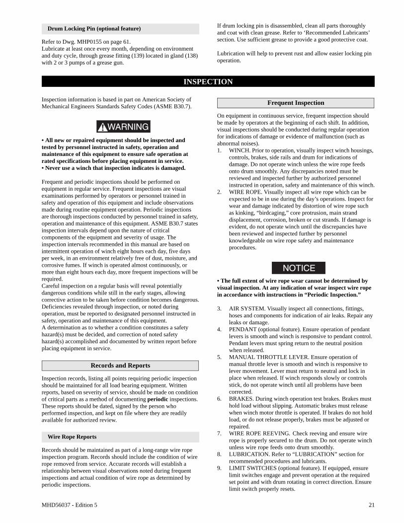
To ensure correct performance, highest efficiency and long life, it is essential that lubricating oil be maintained at correct level. Rotate drum until fill plug is located at top dead center then add oil up to level plug hole. Oil capacity for reduction gear assembly is 4 quarts (3.8 litres).
Reduction Gear Lubrication Plug Locations
(Dwg. MHP0140)
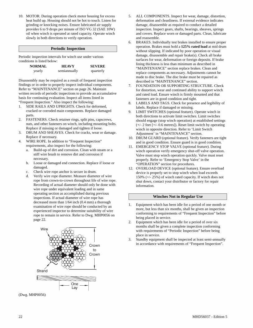
Disc Brake (optional feature)
Refer to Dwg. MHP1348 on page 20.The friction plates and drive plates are in a self contained oil bath and have no other means lubrication. After an oil change or winch overhaul remove the breather plug (22) and pour a small amount of oil [4 to 6 ounces (0.2 litres)] through breather hole in brake housing. Allow oil to fully settle between fillings.
NOTICE• If too much oil is added excess oil will be discharged through breather plug when control valve is actuated.
(Dwg. MHP1348)
Seals and Bearings
If winch is disassembled, clean all parts thoroughly and coat bearings and seals with clean grease. Refer to ‘Recommended Lubricants’ section. Use sufficient grease to provide a good protective coat. Lubricate grease fittings monthly with 2 or 3 pumps of a grease gun.
MHD56037 - Edition 5 21
Drum Locking Pin (optional feature)
Refer to Dwg. MHP0155 on page 61.Lubricate at least once every month, depending on environment and duty cycle, through grease fitting (139) located in gland (138) with 2 or 3 pumps of a grease gun.
If drum locking pin is disassembled, clean all parts thoroughly and coat with clean grease. Refer to ‘Recommended Lubricants’ section. Use sufficient grease to provide a good protective coat.
Lubrication will help to prevent rust and allow easier locking pin operation.
INSPECTION
Inspection information is based in part on American Society of Mechanical Engineers Standards Safety Codes (ASME B30.7).
WARNING• All new or repaired equipment should be inspected and tested by personnel instructed in safety, operation and maintenance of this equipment to ensure safe operation at rated specifications before placing equipment in service.• Never use a winch that inspection indicates is damaged.
Frequent and periodic inspections should be performed on equipment in regular service. Frequent inspections are visual examinations performed by operators or personnel trained in safety and operation of this equipment and include observations made during routine equipment operation. Periodic inspections are thorough inspections conducted by personnel trained in safety, operation and maintenance of this equipment. ASME B30.7 states inspection intervals depend upon the nature of critical components of the equipment and severity of usage. The inspection intervals recommended in this manual are based on intermittent operation of winch eight hours each day, five days per week, in an environment relatively free of dust, moisture, and corrosive fumes. If winch is operated almost continuously, or more than eight hours each day, more frequent inspections will be required.Careful inspection on a regular basis will reveal potentially dangerous conditions while still in the early stages, allowing corrective action to be taken before condition becomes dangerous.Deficiencies revealed through inspection, or noted during operation, must be reported to designated personnel instructed in safety, operation and maintenance of this equipment.A determination as to whether a condition constitutes a safety hazard(s) must be decided, and correction of noted safety hazard(s) accomplished and documented by written report before placing equipment in service.
Records and Reports
Inspection records, listing all points requiring periodic inspection should be maintained for all load bearing equipment. Written reports, based on severity of service, should be made on condition of critical parts as a method of documenting periodic inspections. These reports should be dated, signed by the person who performed inspection, and kept on file where they are readily available for authorized review.
Wire Rope Reports
Records should be maintained as part of a long-range wire rope inspection program. Records should include the condition of wire rope removed from service. Accurate records will establish a relationship between visual observations noted during frequent inspections and actual condition of wire rope as determined by periodic inspections.
Frequent Inspection
On equipment in continuous service, frequent inspection should be made by operators at the beginning of each shift. In addition, visual inspections should be conducted during regular operation for indications of damage or evidence of malfunction (such as abnormal noises).1. WINCH. Prior to operation, visually inspect winch housings,
controls, brakes, side rails and drum for indications of damage. Do not operate winch unless the wire rope feeds onto drum smoothly. Any discrepancies noted must be reviewed and inspected further by authorized personnel instructed in operation, safety and maintenance of this winch.
2. WIRE ROPE. Visually inspect all wire rope which can be expected to be in use during the day’s operations. Inspect for wear and damage indicated by distortion of wire rope such as kinking, “birdcaging,” core protrusion, main strand displacement, corrosion, broken or cut strands. If damage is evident, do not operate winch until the discrepancies have been reviewed and inspected further by personnel knowledgeable on wire rope safety and maintenance procedures.
NOTICE• The full extent of wire rope wear cannot be determined by visual inspection. At any indication of wear inspect wire rope in accordance with instructions in “Periodic Inspection.”
3. AIR SYSTEM. Visually inspect all connections, fittings, hoses and components for indication of air leaks. Repair any leaks or damage.
4. PENDANT (optional feature). Ensure operation of pendant levers is smooth and winch is responsive to pendant control. Pendant levers must spring return to the neutral position when released.
5. MANUAL THROTTLE LEVER. Ensure operation of manual throttle lever is smooth and winch is responsive to lever movement. Lever must return to neutral and lock in place when released. If winch responds slowly or controls stick, do not operate winch until all problems have been corrected.
6. BRAKES. During winch operation test brakes. Brakes must hold load without slipping. Automatic brakes must release when winch motor throttle is operated. If brakes do not hold load, or do not release properly, brakes must be adjusted or repaired.
7. WIRE ROPE REEVING. Check reeving and ensure wire rope is properly secured to the drum. Do not operate winch unless wire rope feeds onto drum smoothly.
8. LUBRICATION. Refer to “LUBRICATION” section for recommended procedures and lubricants.
9. LIMIT SWITCHES (optional feature). If equipped, ensure limit switches engage and prevent operation at the required set point and with drum rotating in correct direction. Ensure limit switch properly resets.
22 MHD56037 - Edition 5
10. MOTOR. During operation check motor housing for excess heat build up. Housing should not be hot to touch. Listen for grinding or knocking noises. Ensure lubricated air supply provides 6 to 9 drops per minute of ISO VG 32 (SAE 10W) oil when winch is operated at rated capacity. Operate winch slowly in both directions to verify operation.
Periodic Inspection
Periodic inspection intervals for winch use under various conditions is listed below:
Disassembly may be required as a result of frequent inspection findings or in order to properly inspect individual components. Refer to “MAINTENANCE” section on page 26. Maintain written records of periodic inspections to provide an accumulative basis for continuing evaluation. Inspect all items listed in “Frequent Inspection.” Also inspect the following:1. SIDE RAILS AND UPRIGHTS. Check for deformed,
cracked or corroded main components. Replace damaged parts.
2. FASTENERS. Check retainer rings, split pins, capscrews, nuts, and other fasteners on winch, including mounting bolts. Replace if missing or damaged and tighten if loose.
3. DRUM AND SHEAVES. Check for cracks, wear or damage. Replace if necessary.
4. WIRE ROPE. In addition to “Frequent Inspection” requirements, also inspect for the following:a. Build-up of dirt and corrosion. Clean with steam or a
stiff wire brush to remove dirt and corrosion if necessary.
b. Loose or damaged end connection. Replace if loose or damaged.
c. Check wire rope anchor is secure in drum.d. Verify wire rope diameter. Measure diameter of wire
rope from crown-to-crown throughout life of wire rope. Recording of actual diameter should only be done with wire rope under equivalent loading and in same operating section as accomplished during previous inspections. If actual diameter of wire rope has decreased more than 1/64 inch (0.4 mm) a thorough examination of wire rope should be conducted by an experienced inspector to determine suitability of wire rope to remain in service. Refer to Dwg. MHP0056 on page 22.
(Dwg. MHP0056)
5. ALL COMPONENTS. Inspect for wear, damage, distortion, deformation and cleanliness. If external evidence indicates damage, disassemble as required to conduct a detailed inspection. Inspect gears, shafts, bearings, sheaves, springs and covers. Replace worn or damaged parts. Clean, lubricate and reassemble.
6. BRAKES. Individually test brakes installed to ensure proper operation. Brakes must hold a 125% rated load at mid drum without slipping. If indicated by poor operation or visual damage, disassemble and repair brake(s). Check all brake surfaces for wear, deformation or foreign deposits. If brake lining thickness is less than minimum as described in “MAINTENANCE” section replace brakes. Clean and replace components as necessary. Adjustments cannot be made to disc brake. The disc brake must be repaired as described in “MAINTENANCE” section.
7. FOUNDATION OR SUPPORTING STRUCTURE. Check for distortion, wear and continued ability to support winch and rated load. Ensure winch is firmly mounted and that fasteners are in good condition and tight.
8. LABELS AND TAGS. Check for presence and legibility of labels. Replace if damaged or missing.
9. LIMIT SWITCHES (optional feature). Operate winch in both directions to activate limit switches. Limit switches should engage (stop winch operation) at established settings (+/- 2 feet [+/- 0.6 metres]). Reset limit switch by operating winch in opposite direction. Refer to ‘Limit Switch Adjustment’ in “MAINTENANCE” section.
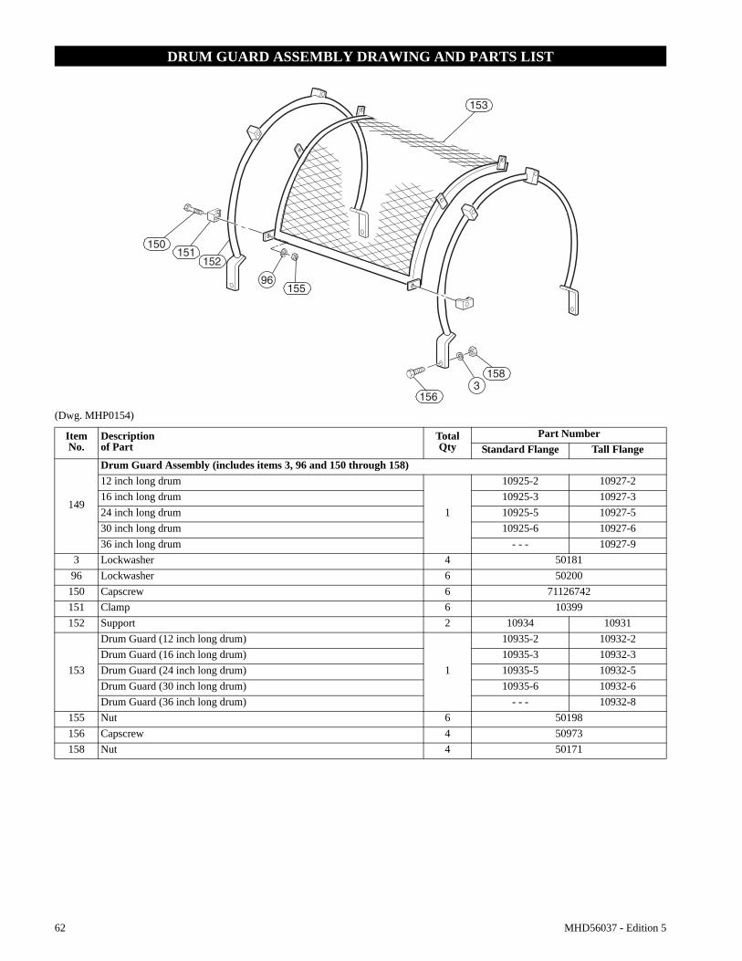
10. DRUM GUARD (optional feature). Verify fasteners are tight and in good condition. Ensure guard is in good condition.
11. EMERGENCY STOP VALVE (optional feature). During winch operation verify emergency shut-off valve operation. Valve must stop winch operation quickly. Valve must reset properly. Refer to ‘Emergency Stop Valve’ in the “OPERATION” section for procedures.
12. OVERLOAD DEVICE (optional feature). Ensure overload device is properly set to stop winch when load exceeds 150% (+/- 25%) of winch rated capacity. If winch does not shut down, contact your distributor or factory for repair information.
Winches Not in Regular Use
1. Equipment which has been idle for a period of one month or more, but less than six months, shall be given an inspection conforming to requirements of “Frequent Inspection” before being placed in service.
2. Equipment which has been idle for a period of over six months shall be given a complete inspection conforming with requirements of “Periodic Inspection” before being place in service.
3. Standby equipment shall be inspected at least semi-annually in accordance with requirements of “Frequent Inspection”.
NORMAL HEAVY SEVEREyearly semiannually quarterly
MHD56037 - Edition 5 23
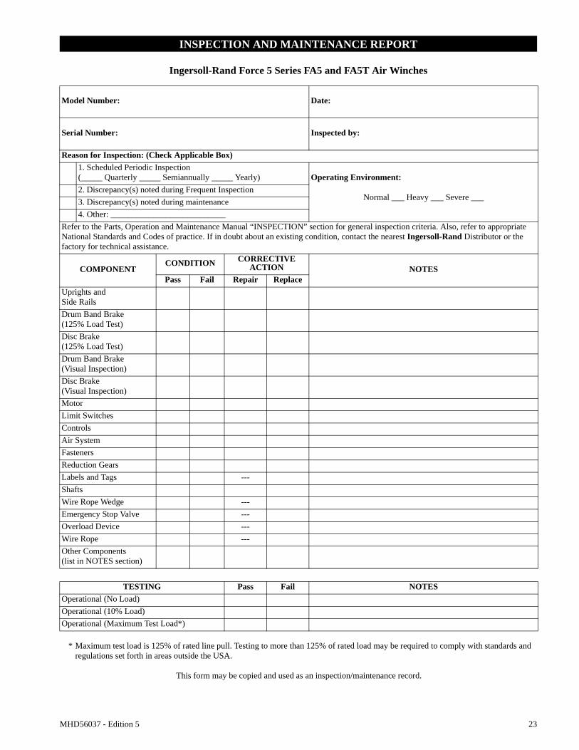
INSPECTION AND MAINTENANCE REPORT
Ingersoll-Rand Force 5 Series FA5 and FA5T Air Winches
Normal ___ Heavy ___ Severe ___2. Discrepancy(s) noted during Frequent Inspection3. Discrepancy(s) noted during maintenance4. Other: ___________________________
Refer to the Parts, Operation and Maintenance Manual “INSPECTION” section for general inspection criteria. Also, refer to appropriate National Standards and Codes of practice. If in doubt about an existing condition, contact the nearest Ingersoll-Rand Distributor or the factory for technical assistance.
COMPONENTCONDITION CORRECTIVE
ACTION NOTESPass Fail Repair Replace
Uprights and Side RailsDrum Band Brake (125% Load Test)Disc Brake (125% Load Test)Drum Band Brake (Visual Inspection)Disc Brake (Visual Inspection)MotorLimit SwitchesControlsAir SystemFastenersReduction GearsLabels and Tags ---ShaftsWire Rope Wedge ---Emergency Stop Valve ---Overload Device ---Wire Rope ---Other Components (list in NOTES section)
TESTING Pass Fail NOTESOperational (No Load)Operational (10% Load)Operational (Maximum Test Load*)
* Maximum test load is 125% of rated line pull. Testing to more than 125% of rated load may be required to comply with standards and regulations set forth in areas outside the USA.
This form may be copied and used as an inspection/maintenance record.
24 MHD56037 - Edition 5
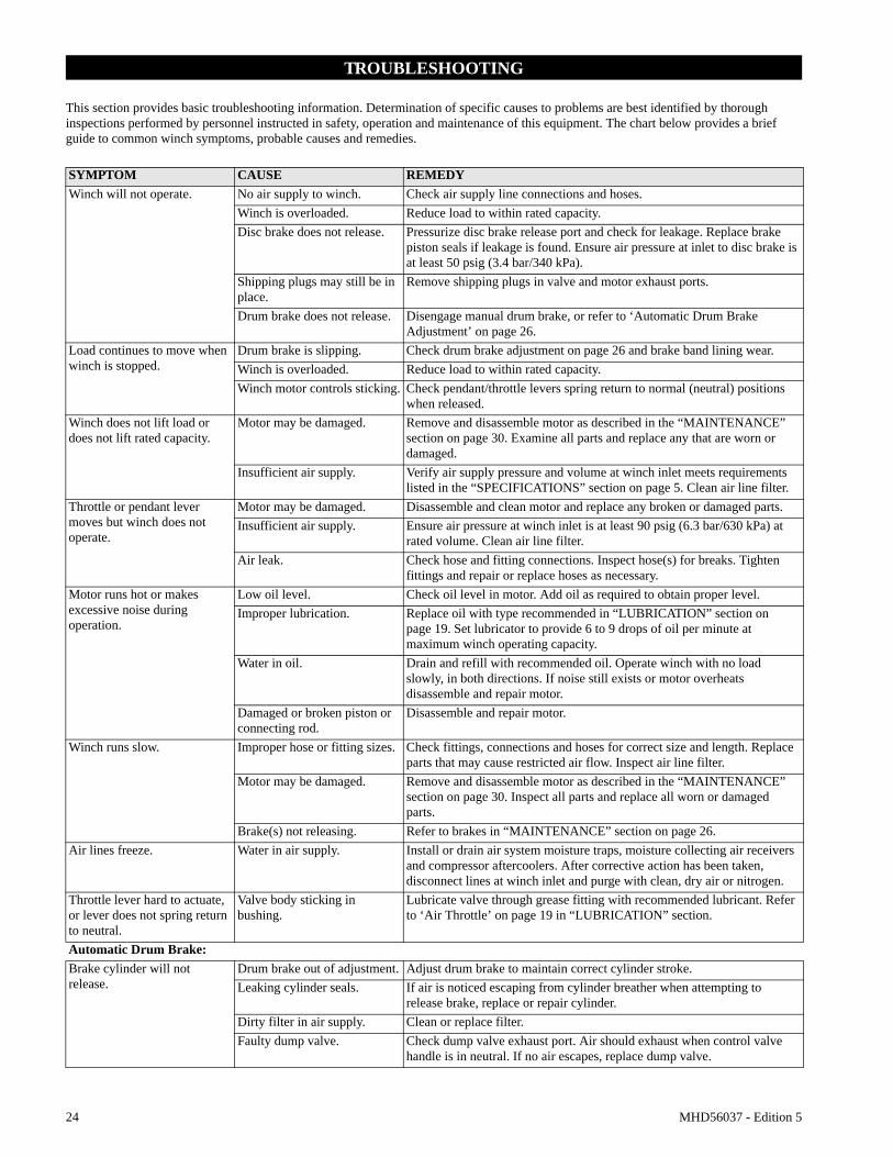
TROUBLESHOOTING
This section provides basic troubleshooting information. Determination of specific causes to problems are best identified by thorough inspections performed by personnel instructed in safety, operation and maintenance of this equipment. The chart below provides a brief guide to common winch symptoms, probable causes and remedies.
SYMPTOM CAUSE REMEDYWinch will not operate. No air supply to winch. Check air supply line connections and hoses.
Winch is overloaded. Reduce load to within rated capacity.Disc brake does not release. Pressurize disc brake release port and check for leakage. Replace brake
piston seals if leakage is found. Ensure air pressure at inlet to disc brake is at least 50 psig (3.4 bar/340 kPa).
Shipping plugs may still be in place.
Remove shipping plugs in valve and motor exhaust ports.
Drum brake does not release. Disengage manual drum brake, or refer to ‘Automatic Drum Brake Adjustment’ on page 26.
Load continues to move when winch is stopped.
Drum brake is slipping. Check drum brake adjustment on page 26 and brake band lining wear.Winch is overloaded. Reduce load to within rated capacity.Winch motor controls sticking. Check pendant/throttle levers spring return to normal (neutral) positions
when released.Winch does not lift load or does not lift rated capacity.
Motor may be damaged. Remove and disassemble motor as described in the “MAINTENANCE” section on page 30. Examine all parts and replace any that are worn or damaged.
Insufficient air supply. Verify air supply pressure and volume at winch inlet meets requirements listed in the “SPECIFICATIONS” section on page 5. Clean air line filter.
Throttle or pendant lever moves but winch does not operate.
Motor may be damaged. Disassemble and clean motor and replace any broken or damaged parts.Insufficient air supply. Ensure air pressure at winch inlet is at least 90 psig (6.3 bar/630 kPa) at
rated volume. Clean air line filter.Air leak. Check hose and fitting connections. Inspect hose(s) for breaks. Tighten
fittings and repair or replace hoses as necessary.Motor runs hot or makes excessive noise during operation.
Low oil level. Check oil level in motor. Add oil as required to obtain proper level.Improper lubrication. Replace oil with type recommended in “LUBRICATION” section on
page 19. Set lubricator to provide 6 to 9 drops of oil per minute at maximum winch operating capacity.
Water in oil. Drain and refill with recommended oil. Operate winch with no load slowly, in both directions. If noise still exists or motor overheats disassemble and repair motor.
Damaged or broken piston or connecting rod.
Disassemble and repair motor.
Winch runs slow. Improper hose or fitting sizes. Check fittings, connections and hoses for correct size and length. Replace parts that may cause restricted air flow. Inspect air line filter.
Motor may be damaged. Remove and disassemble motor as described in the “MAINTENANCE” section on page 30. Inspect all parts and replace all worn or damaged parts.
Brake(s) not releasing. Refer to brakes in “MAINTENANCE” section on page 26.Air lines freeze. Water in air supply. Install or drain air system moisture traps, moisture collecting air receivers
and compressor aftercoolers. After corrective action has been taken, disconnect lines at winch inlet and purge with clean, dry air or nitrogen.
Throttle lever hard to actuate, or lever does not spring return to neutral.
Valve body sticking in bushing.
Lubricate valve through grease fitting with recommended lubricant. Refer to ‘Air Throttle’ on page 19 in “LUBRICATION” section.
Automatic Drum Brake:Brake cylinder will not release.
Drum brake out of adjustment. Adjust drum brake to maintain correct cylinder stroke.Leaking cylinder seals. If air is noticed escaping from cylinder breather when attempting to
release brake, replace or repair cylinder.Dirty filter in air supply. Clean or replace filter.Faulty dump valve. Check dump valve exhaust port. Air should exhaust when control valve
handle is in neutral. If no air escapes, replace dump valve.
MHD56037 - Edition 5 25
SYMPTOM CAUSE REMEDYAutomatic Disc Brake:Brake fails to release. Low air supply pressure. Ensure air pressure at inlet to disc brake is at least 50 psig (3.4 bar/340
kPa).Leaking piston seals. Inspect brake breather. If air escapes from brake breather when attempting
to release brake, replace brake seals.No release pressure at brake port.
Check for proper operation of winch controls.
Sticking brake piston. Apply 50 psig (3.4 bar/340 kPa) to brake release port and check for brake disc movement. (Brake discs can be viewed through brake breather hole.) If brake discs do not move, disassemble and inspect disc brake as described in “MAINTENANCE” section.
26 MHD56037 - Edition 5
MAINTENANCE
WARNING• Never perform maintenance on winch while it is supporting a load.• Before performing maintenance, tag controls:
WARNING - DO NOT OPERATE -EQUIPMENT BEING REPAIRED.
• Only allow service personnel trained in safety and service on this winch to perform maintenance.• After performing any maintenance on winch, test winch to 125% of its rated capacity before returning to service. Testing to more than 125% of rated capacity may be required to comply with standards outside the USA.• Shut off air system and depressurize air lines before performing any maintenance.
Maintenance Intervals
The Maintenance Interval chart is based on intermittent operation of winch eight hours each day, five days per week. If winch operation exceeds eight hours per day, or use is under HEAVY or SEVERE conditions, more frequent maintenance should be performed. Refer to ‘Periodic Inspection’ on page 22 in “INSPECTION” section for interval guidance.
Adjustments
Disc Brake Adjustment (optional feature)
Refer to Dwg. MHP0152 on page 46.Disc brake adjustment is not required. If disc brake does not hold rated load disassemble and repair.If brake assembly is removed or disassembled ensure breather (23) is installed and located at top of brake housing during reassembly.
Manual Drum Brake Adjustment
Refer to Dwg. MHP0153 on page 48.1. Release wire rope tension on drum.2. Raise handle (104) to free brake bands (128).3. Remove cotter pin (102) and pin (101).
4. Rotate link stud (103) clockwise to increase brake torque.5. Install pin (101) and check adjustment.6. Brake should be adjusted until brake lever over center
position can be attained with 50 to 100 lb. (23 to 45 kg) force on handle (104).
7. Install cotter pin (102) when adjustment is completed. Bend ends of cotter pin over.
CAUTION
• When any part of brake lining measures 0.062 inch (2 mm) or less, brake bands (128) or linings must be replaced.
Refer to Dwg. MHP0153 on page 48.1. Remove cotter pin (102) and washer (129) at adjustment
clevis (107).2. Apply air to brake cylinder (110) and remove pin (106) and
second washer (129) to disconnect clevis from brake lever (105).
3. Turn adjustment clevis (107) clockwise to increase cylinder rod extension. Turn clevis counterclockwise to decrease cylinder rod extension.
4. Assemble clevis (107) to brake lever (105) with washer (129) and pin (106). Release air to brake cylinder (110).
5. Measure cylinder rod extension. Length should be 1 to 1-1/2 inches (25 to 37 mm). Readjust if necessary.
6. Install cotter pin (102) and second washer (129) to secure clevis to brake lever when adjustment is complete.
7. With brake “On”, adjust screw (127) to just touch arm (124).
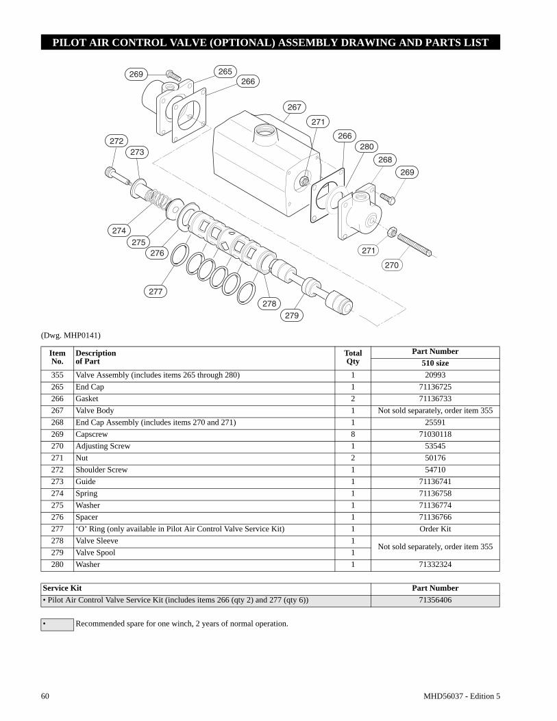
Pilot Air Control Valve Adjustment (optional feature)
Refer to Dwg. MHP0141 on page 60.If winch operating speeds differ from performance specifications pilot air control valve may require adjustment. Loosen nut (271) and adjust adjusting screw (270), located in valve end cap (268), until drum speed for no-load haul-in equals drum speed for full load payout. Rotate screw (270) ‘out’ to increase drum speed and ‘in’ to decrease drum speed. It is suggested that a chalk mark be placed on drum flange so that drum rpm can be accurately counted.
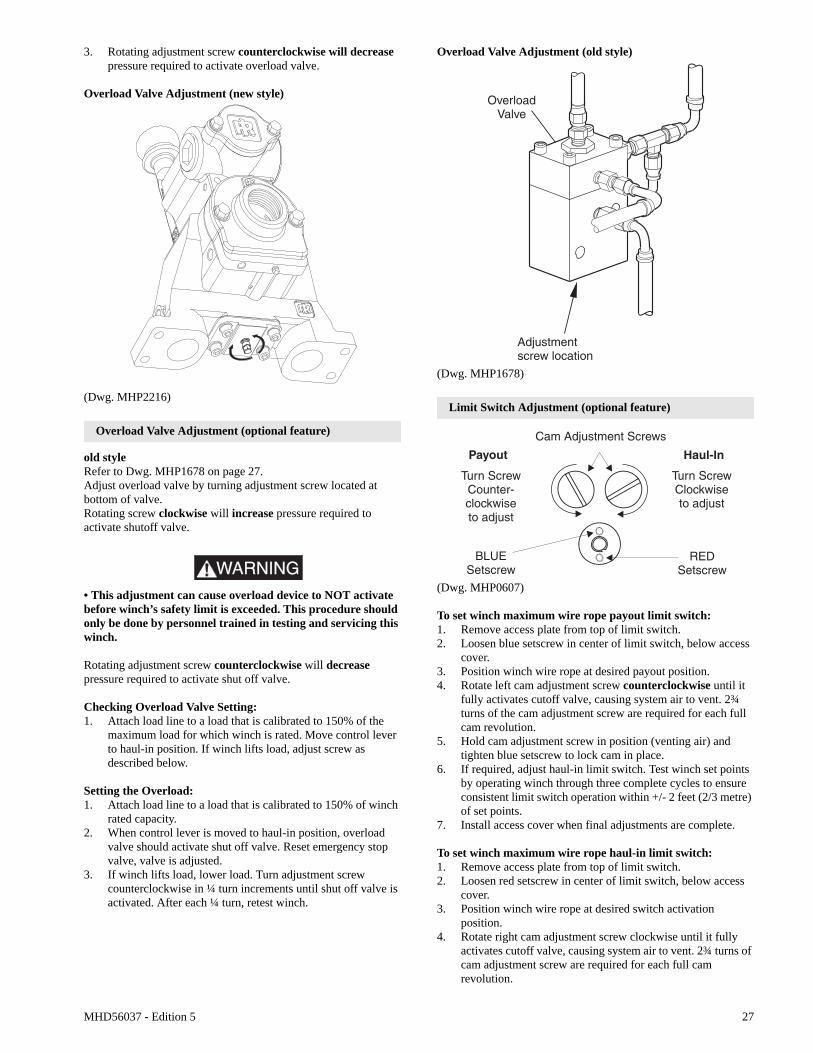
Overload Valve Adjustment (optional feature)
new styleRefer to Dwg. MP2216 on page 275/16 in. or 8 mm open ended wrench required.1. Adjust overload valve by turning adjustment screw located at
bottom of control valve.2. Rotating adjustment screw clockwise will increase pressure
required to activate overload valve.
WARNING• This adjustment can cause overload device to NOT activate before winch’s safety limit is exceeded. This procedure should only be done by personnel trained in testing and servicing this winch.
INTERVAL MAINTENANCE CHECK
Start of each shift
(Operator orMaintenancePersonnel)
Make a thorough visual inspection of winch for damage. Do not operate winch if damaged.
Operate winch at low RPM in both directions. Winch must operate smoothly without sticking, binding or abnormal noises. Check operation of brake(s)
3 Months(MaintenancePersonnel)
Inspect drum brake friction linings. Clean or replace parts as required. Adjust drum brake as necessary.
Yearly
(MaintenancePersonnel)
Inspect winch gearing, shafts and bearings for wear and damage. Repair or replace as necessary.
Check all supporting members, including foundation, fasteners, nuts, sheaves and rigging, etc. for indications of damage or wear. Repair or replace as required.
MHD56037 - Edition 5 27
3. Rotating adjustment screw counterclockwise will decrease pressure required to activate overload valve.
Overload Valve Adjustment (new style)
(Dwg. MHP2216)
Overload Valve Adjustment (optional feature)
old styleRefer to Dwg. MHP1678 on page 27.Adjust overload valve by turning adjustment screw located at bottom of valve.Rotating screw clockwise will increase pressure required to activate shutoff valve.
WARNING• This adjustment can cause overload device to NOT activate before winch’s safety limit is exceeded. This procedure should only be done by personnel trained in testing and servicing this winch.
Rotating adjustment screw counterclockwise will decrease pressure required to activate shut off valve.
Checking Overload Valve Setting:1. Attach load line to a load that is calibrated to 150% of the
maximum load for which winch is rated. Move control lever to haul-in position. If winch lifts load, adjust screw as described below.
Setting the Overload:1. Attach load line to a load that is calibrated to 150% of winch
rated capacity.2. When control lever is moved to haul-in position, overload
valve should activate shut off valve. Reset emergency stop valve, valve is adjusted.
3. If winch lifts load, lower load. Turn adjustment screw counterclockwise in ¼ turn increments until shut off valve is activated. After each ¼ turn, retest winch.
Overload Valve Adjustment (old style)
(Dwg. MHP1678)
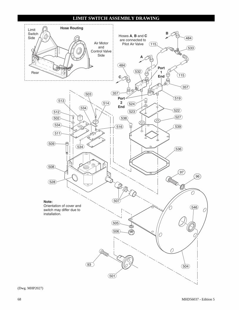
Limit Switch Adjustment (optional feature)
(Dwg. MHP0607)
To set winch maximum wire rope payout limit switch:1. Remove access plate from top of limit switch.2. Loosen blue setscrew in center of limit switch, below access
cover.3. Position winch wire rope at desired payout position.4. Rotate left cam adjustment screw counterclockwise until it
fully activates cutoff valve, causing system air to vent. 2¾ turns of the cam adjustment screw are required for each full cam revolution.
5. Hold cam adjustment screw in position (venting air) and tighten blue setscrew to lock cam in place.
6. If required, adjust haul-in limit switch. Test winch set points by operating winch through three complete cycles to ensure consistent limit switch operation within +/- 2 feet (2/3 metre) of set points.
7. Install access cover when final adjustments are complete.
To set winch maximum wire rope haul-in limit switch:1. Remove access plate from top of limit switch.2. Loosen red setscrew in center of limit switch, below access
cover.3. Position winch wire rope at desired switch activation
position.4. Rotate right cam adjustment screw clockwise until it fully
activates cutoff valve, causing system air to vent. 2¾ turns of cam adjustment screw are required for each full cam revolution.
28 MHD56037 - Edition 5
5. Hold cam adjustment screw in position (venting air) and tighten red setscrew.
6. If required, adjust payout limit switch. Test winch set points by operating winch through three complete cycles to ensure consistent limit switch operation within +/- 2 feet (2/3 metre) of set points.
7. Install access cover when final adjustments are complete.
Constant Tension Adjustment (optional feature)
Refer to Dwg. MHP1865 on page 12.The regulator is preset at 0 psig (0 bar/0 kPa), therefore requires adjustment when winch is installed. To adjust for specific load applications, regulator pressure may be adjusted to increase or decrease tension setting.Regulator gauge and regulator are accessible through cover.
WARNING• When adjusting regulator, ensure winch control lever is locked in neutral position and tension selector lever is in the NORMAL position.• Winch supply air is NOT shut off during regulator adjustments. To prevent accidental winch operation, allow only a single person, trained in safety, operation and maintenance of this product, to conduct regulator adjustments.
Regulator Adjustment Procedure:Refer to Dwg. MHP1865 on page 12.1. Attach test load of desired weight to load line, or connect
load line to scale.
WARNING• Ensure load line is connected to load and excessive slack is taken up before activating auxiliary valve. When activated, auxiliary valve will automatically engage and winch will operate at full speed to set tension on load line.
2. With winch control valve remove all slack from load line.
Setting with test load:1. Actuate auxiliary valve to TENSIONING position. Winch
should operate, causing load line to become taut. To increase tension, turn regulator knob clockwise until load begins to rise. Turn regulator knob counterclockwise a minimum of ¼ turn, or until load is balanced (does not raise or lower). Note pressure indicated on gauge for future setting reference.
Setting with scale:1. Actuate auxiliary valve to TENSIONING position. Winch
should operate, causing load line to become taut. To increase tension, turn regulator knob clockwise until scale indicates desired tension. Note pressure indicated on gauge for future setting reference.
Disassembly
General Disassembly Instructions
The following instructions provide necessary information to disassemble, inspect, repair, and assemble winch. Parts drawings are provided in parts section. If a winch is being completely disassembled for any reason, follow the order of topics as they are presented. It is recommended that all maintenance work on winch be performed in a clean dust free work area.In the process of disassembling winch, observe the following:1. Never disassemble winch any further than is necessary to
accomplish needed repair. A good part can be damaged during the course of disassembly.
2. Never use excessive force when removing parts. Tapping gently around perimeter of a cover or housing with a soft hammer, for example, is sufficient to break the seal.
3. Do not heat a part with a flame to free it for removal, unless part being heated is already worn or damaged beyond repair and no additional damage will occur to other parts.
In general, winch is designed to permit easy disassembly and assembly. The use of heat or excessive force should not be required.
4. Keep work area as clean as practical, to prevent dirt and other foreign matter from getting into bearings or other moving parts.
5. All seals and ‘O’ rings should be discarded once they have been removed. New seals and ‘O’ rings should be used when assembling winch.
6. When grasping a part in a vise, always use leather-covered or copper-covered vise jaws to protect the surface of part and help prevent distortion. This is particularly true of threaded members, machined surfaces and housings.
7. Do not remove any part which is a press fit in or on a subassembly unless removal of that part is necessary for repairs or replacement.
8. When removing ball bearings from shafts, it is best to use a bearing puller. When removing bearings from housings, drive out bearing with a sleeve slightly smaller than outside diameter of bearing. The end of sleeve or pipe which contacts bearing must be square. Protect bearings from dirt by keeping them wrapped in clean cloths.
Winch Disassembly
Refer to Dwg. MHP0157 on page 40, MHP2093 on page 44 and MHP0152 on page 46.1. Remove wire rope from drum.2. Operate winch to position reduction gear drain plug at it’s
lowest position.3. Relieve pressure in air lines by operating winch control
several times after air supply has been turned off.
WARNING• Shut off, bleed down and disconnect air supply line before performing any disassembly procedures.
4. Disconnect and tag air lines.5. Remove winch from its mounting and take to a suitable work
area before beginning disassembly.6. Remove lower case drain plug (225) on K5B motor housing
(217) and allow oil to drain into a suitable container. Loosen fill cap (210) to vent motor housing.
MHD56037 - Edition 5 29
7. Drain oil from reduction gear assembly by removing one plug (48) when positioned at it’s lowest point, and one plug (48) from it’s highest point to vent. Refer to Dwg. MHP0140 on page 20 in “LUBRICATION” section. If winch is equipped with a drum band brake elevate winch outboard end (opposite from motor end) to prevent draining oil from contaminating brake band lining.
8. For winches with a disc brake remove pipe plug (24) in brake housing (21) to drain brake oil.
9. Remove drum band brake, drum guard and any other externally mounted winch attachments.
WARNING• The K5B air motor weighs approximately 260 lb. (118 kg). Adequately support air motor before removing motor mounting capscrews.
10. Remove capscrews (4) and lockwashers (3) securing motor assembly to motor adapter (6). Using a hoist to support motor, pull motor straight away from winch. Reference the applicable Motor Disassembly section if motor disassembly is required.
Instructions 11 through 17 apply only to winches with a disc brake.
11. Alternately and evenly loosen eight capscrews (1) until brake spring tension has been released. Remove capscrews and motor adapter (6).
12. Remove brake housing (21). If brake housing sticks, tap it with a soft faced hammer until parts separate.
Note position of all brake parts for reassembly.
13. Remove three friction plates (16) and two drive plates (17).14. Remove springs (9) from brake piston (10).15. Remove brake piston (10) from brake housing (21). Tap
lightly with a plastic mallet to separate parts if necessary.16. Remove seals (11) and (12) from brake piston (10).17. Loosen capscrew in collar (18) and slide collar from shaft
(35) with splined hub (19) and spacer (34) from shaft (35).18. Remove retainer ring (36) from bore of drum shaft (41).19. Pull shaft and bearing assembly from drum shaft (41).20. Support drum (80) and remove capscrews (39) from drum
shaft (41). Pry drum shaft (41) from inboard upright (42).21. Remove capscrews (85) and lockwashers (86) which secure
side rails (82) and (83) to inboard upright (42). Drive out dowel pins (87).
22. Remove inboard upright (42).23. Remove end cover (95), capscrews (97) and lockwashers
(96) from outboard upright (84).24. Remove capscrews (93) and shaft retainer (92) from drum
(80).25. Remove drum and reduction gear assembly.26. Remove remaining capscrews (85) and lockwashers (86)
which attach side rails (82) and (83) to outboard upright (84). Drive out dowel pins (87).
27. Remove bearing (49) and seal (99) from outboard upright (84).
28. Remove capscrews (45) and lockwashers (46) securing gear carrier (47) to drum (80).
29. Install two 3/4 inch - 10 NC x 3 inch long capscrews into threaded holes in outer bolt pattern ring of gear carrier (47). Use these capscrews to break seal. Remove reduction gear/gear carrier assembly from drum (80).
To disassemble reduction gear refer to Reduction Gear Disassembly section.
Manual or Automatic Drum Brake Disassembly
Refer to Dwg. MHP0153 on page 48.1. Automatic Brake
a. Disconnect and remove hose, fittings and dump valve (112) from cylinder (110).
b. Remove cotter pin (102) and pin (101) from link stud (103) and brake band (128).
c. Remove cotter pin (102), washers (129) and pin (106). Separate clevis (107) from brake lever (105).
d. Remove cotter pin (102) and pin (134). Remove cylinder (110) from bracket (118).
2. Manual Brake:a. Remove cotter pin (102) and pin (101) from handle
(104) then remove handle (104) from brake band (128).3. Remove capscrews (119), lockwashers (117) and stop plate
(126).4. Use a hoist to raise winch approximately 6 inches (15 cm).
Separate brake band (128) halves and rotate brake band assembly slowly until it can be removed from drum (80).
5. Remove cotter pins (102) and pins (121) so brake band halves (128) can be removed from arm (124). Lower winch when brake band assembly has been removed.
6. Refer to ‘Brake Lining Instruction Sheet’ (Form MHD56142) for brake lining replacement procedures.
Reduction Gear Disassembly
Refer to Dwg. MHP0157 on page 40.
NOTICE• It is important to maintain a clean work area when reduction gear assembly is disassembled.
1. Place reduction gear assembly on a clean work bench such that end containing bearing (49) is down.
2. Remove capscrews (75) and pry off cover (73).3. Remove ring gear (72), planet assembly (67) and sun gear
(69).4. Remove and discard ‘O’ rings (62) from ring gear (72).5. Remove four pins (74) from between cover (73) and spacer
(71) and store in a safe place.6. Remove spacer (71), ring gear (63) and sun gear (66).7. If required, remove thrust plate (55) from sun gear (66).
Remove and discard ‘O’ rings (62) from ring gear (63).8. Remove capscrews (60) from input housing (59). Separate
input housing from gear carrier (47).9. Remove planet assembly (58).10. Remove ring gear (53). Remove three dowel pins (52) from
between input housing (59) and gear carrier (47) and store in a safe place.
11. Remove and discard ‘O’ rings (51) from ring gear (53).12. Remove retainer ring (57) and sun gear (56). If required,
remove thrust plate (55) from sun gear.13. Remove planet assembly (54).14. Remove retainer ring (50) and bearing (49) from gear carrier
(47).
30 MHD56037 - Edition 5
NOTICE• Do not disassemble planetary gear assemblies (54), (58) and (67).
K5B Motor Disassembly
Refer to Dwg. MHP2093 on page 44.1. Remove five capscrews (1) from exhaust flange (253) or
(254). Do not remove the two capscrews (255) from throttle valve assembly (260).
2. Remove rotary valve housing (247) by pulling it out of motor housing (217) as an assembly with exhaust flange (253) or (254).
CAUTION
• Do not remove the exhaust flange (254) until rotary valve (250) has been removed from rotary valve housing (247).
3. Remove rotary valve (250) by pulling it out from assembly through the motor housing end of rotary valve housing (247).
4. Remove exhaust flange (254) and throttle valve assembly (260) by removing capscrews (255) and (257), respectively.
5. Remove each cylinder head (201) by removing four capscrews (200). Remove head gasket (209).
6. Pull cylinder liner (208) straight out.7. Position piston (204) at top of its stroke. In this position,
with cylinder liner pulled out in step 7, wrist pin (203) can be removed. Remove one retainer ring (205) from either side of piston (204). Push wrist pin (203) out by hand from one side. If wrist pin is too tight it is acceptable to carefully heat piston to 200° F (93° C) or less and then push wrist pin out.
NOTICE• If piston, wrist pin, connecting rod or cylinder liner are to be re-assembled, number each set. Also add radial alignment marks for each piston and cylinder liner to motor housing.
8. Remove remaining cylinder liners and pistons as described in steps 7 and 8. To remove crank assembly, all pistons and cylinder liners must be removed.
9. Crank assembly (231) can now be removed with oil slinger (230) by pulling straight out from motor housing (217). Use care while guiding connecting rods (206) through inside of motor housing.
Crankshaft Disassembly
1. Remove cotter pin (236) and pin nut (237).2. Remove lock pin (235) by carefully driving it out of its
location. Use care not to damage pin threads.3. Pull crankshaft valve end (231) off crankshaft.4. Remove connecting rod rings (234), connecting rod bushing
(233), sleeve (232) and connecting rods (206). Record five connecting rod (206) numbers and foot directions so they can be re-installed in same order.
5. Oil slinger (230) does not have to be removed unless damaged. If removal is required, heating of five screws (229) may be necessary to loosen Loctite® connection.
Control Valve Removal and Replacement
Refer to Dwg. MHP2036 on page 50 or MHP0165 on page 54.Replacement of K5B control valve with K5C2 control valve.1. Turn off air supply to valve and disconnect main air supply
line at motor.2. Disconnect auxiliary air line(s) from fitting(s) located on
control valve.3. Remove muffler and/or exhaust piping.4. Remove capscrews (1) and (255), and washers (96) from
exhaust flange cap (254). Discard gasket (317).5. Remove capscrews (257) and washers (96) from control
valve.6. Remove control valve from rotary housing and discard
gasket (248).7. Install gaskets (946) and control valve assembly (900)
securing with capscrews (951) and washers (949).8. Install gasket (970) and exhaust cap (971) to rotary housing
on motor.9. Install fittings (957), (958) and muffler (959) on control
valve. These are optional parts.
K5C2 Control Valve Disassembly
Refer to Dwg. MHP2036 on page 50.
Handle Removal
It is not recommended to disassemble handle.1. Carefully pry off plug (935).2. Remove capscrew (901) and tablock washer (909).
NOTICE• Observe spring (937) connection during disassembly. This spring is under tension and is required to return handle to neutral position.
3. Carefully pull handle assembly (930) from reverse valve (943). Remove spring (937).
Reverse Valve Removal
1. Remove capscrews (938), (925) and washers (924) from seal bracket (939). Remove seal bracket from housing. Remove and discard ‘O’ rings (941) and (942).
2. Remove capscrews (901) and washers (902) from exhaust flange (955). Remove flange from housing. Remove and discard ‘O’ ring (942).
3. Move reverse valve (943) out exhaust flange side of housing until ball (916) is visible on reverse valve. Allow ball (916) to drop out of bushing (944) and remove ball (916).
4. Remove bushing (944) out exhaust flange side of housing.
NOTICE• Dowel pin (945) allows the bushing to be removed only from the exhaust flange side of housing. Ball (916) retains reverse valve (943) in bushing (944).• Do not remove reverse valve (943), bushing (944) and ball (916) at the same time, damage may occur to bushing.• Take care to not allow ball (916) to drop in motor. If this occurs it may be necessary to disassemble motor to retrieve ball (916).
MHD56037 - Edition 5 31
Piston Removal
1. Remove capscrews (901) and washers (902) from piston cover (919). Remove cover and discard gasket (918).
2. Remove capscrews (901) and washers (902) from poppet cover (903). Remove cover and discard gasket (904).
3. Remove the following items from housing poppet bore: spring (905), poppet cap (906) and poppet seal (907).
4. From poppet side, push piston (922) out of housing. Remove ‘O’ rings (921) and (923) and discard.
Pilot Valve Removal
NOTICE• For easier removal it is recommended to use IR pilot valve tool (920). This must be purchased separately.
If pilot valve is not damaged it is not necessary to disassemble completely.1. Remove plug (912).2. Remove pilot valve assembly (910) as an assembly.3. Discard and replace pilot valve assembly (910) if necessary.
K5B Control Valve Disassembly (old style)
Refer to Dwg. MHP0165on page 54.
NOTICE• Match mark throttle valve parts to ensure proper re-assembly.
1. Remove two capscrews (302) and lockwashers (96) that hold the valve body retainer (305).
2. Mark square end on valve body (316) and handle (300) to ensure correct orientation during reassembly.
3. Drive out pin (301) and remove handle (300).4. Make note on how spring (303) is positioned before
removing it. Pull valve body (316) out of valve bushing (314) while disconnecting spring (303).
5. Remove seal rings (315) from valve body (316).6. Check parts for score marks or wear. 7. Measure clearance between valve bushing (314) and valve
body (316). Clearance between valve bushing and valve body should not exceed 0.002 inch (0.05 mm) or excessive air leakage will occur.
K5C2-E Control Valve Disassembly
Refer to Dwg. MHP 2180 on page 52.
Handle Removal
Follow disassembly instructions for K5C2 Control Valve.
Reverse Valve Removal
1. Remove capscrews (938), (925) and washers (924) from seal bracket (939). Remove seal bracket from housing. Remove and discard ‘O’ rings (941) and (942).
2. Remove capscrews (721) and washers (902) from exhaust flange (955) and exhaust adapter (723). Remove and discard ‘O’ rings (942) and (722).
3. Move reverse valve (943) out exhaust flange side of housing until ball (916) is visible on reverse valve. Allow ball (916) to drop out of bushing (944) and remove ball (916).
4. Remove bushing (944) out exhaust flange side of housing.
NOTICE• Dowel pin (945) allows the bushing to be removed only from the exhaust flange side of housing. Ball (916) retains reverse valve (943) in bushing (944).• Do not remove reverse valve (943), bushing (944) and ball (916) at the same time, damage may occur to bushing.
Piston Removal
Follow disassembly instructions for K5C2 Control Valve.
Pilot Valve Removal
Follow disassembly instructions for K5C2 Control Valve.
Emergency Stop Removal
1. Remove adapter (706) and E-Stop button (705).2. Remove plunger (707). Remove and discard ‘O’ rings (703).3. Pull spring (711) out of valve housing and discard.
Overload Valve Removal
1. Remove cap (700). Remove and discard grommet (701).2. Pull out plunger (702), remove and discard ‘O’ rings (703).3. Remove capscrews (901) and washers (902) from cover
(719) underneath valve housing.
NOTICE• Cover (719) retains spring (718). To remove capscrews (901) and washer (902) unscrew in a crisscross pattern.
4. Remove adjusting screw (720).
Cleaning, Inspection and Repair
Clean all winch component parts in solvent (except drum brake bands and disc brake friction plates). The use of a stiff bristle brush will facilitate removal of accumulated dirt and sediments on housings, frame and drum. If bushings have been removed it may be necessary to scrape old Loctite® from bushing bores. Dry each part using low pressure, filtered compressed air. Clean drum brake band using a wire brush or emery cloth. Do not wash drum brake band in solvent. If drum brake band lining is oil soaked, it must be replaced.
Inspection
All disassembled parts should be inspected to determine their fitness for continued use. Pay particular attention to the following:1. Inspect all gears for worn, cracked, or broken teeth.2. Inspect all bushings for wear, scoring, or galling.3. Inspect shafts for ridges caused by wear. If ridges caused by
wear are apparent on shafts, replace shaft. 4. Inspect all threaded items and replace those having damaged
threads.
32 MHD56037 - Edition 5
5. Inspect drum band brake lining for oil, grease and glazing. If drum band brake lining is oil-soaked replace brake bands as a set. Remove glazed areas of band brake lining by sanding lightly with a fine grit emery cloth.
6. Measure thickness of drum band brake lining. If drum brake band linings are less than 0.062 inch (2 mm) thick anywhere along edges replace brake bands (128) as a set.
7. Inspect cylinder bores. Minor scratches in bore lining may be repaired by lightly honing to remove. Refer to tolerances listed below for acceptable clearances. Replace liner if deep scratches or gouges are apparent. Measure inside diameter of liner. If measurement is greater than 4.764 inches (121 mm) replace liner. ‘Ring Gap’ may also be used to determine wear; place compression ring into liner, using a piston, push ring until approximately half way in liner and measure ‘Gap’ — 0.003 inch (0.076 mm) is normal; replace rings, or liner, if ‘Gap’ exceeds 0.020 inch (0.51 mm).
Repair
Actual repairs are limited to removal of small burrs and other minor surface imperfections from gears and shafts. Use a fine stone or emery cloth for this work. 1. Worn or damaged parts must be replaced. Refer to the
applicable parts listing for specific replacement parts information.
2. Inspect all remaining parts for evidence of damage. Replace or repair any part which is in questionable condition. Cost of the part is often minor in comparison with cost of redoing job.
3. Smooth out all nicks, burrs, or galled spots on shafts, bores, pins, or bushings.
4. Examine all gear teeth carefully, and remove nicks or burrs.5. Polish edges of all shaft shoulders to remove small nicks
which may have been caused during handling.6. Remove all nicks and burrs caused by lockwashers.
Assembly
General instructions
• Use all new gaskets and seals.• Replace worn parts.• Assemble parts using match marks attached during
disassembly. Compare replacement parts with originals to identify installation alignments.
• Lubricate all internal parts with rust and oxidation inhibiting lubricant, ISO VG 100 (SAE 30W).
K5C2 Control Valve Assembly
Refer to Dwg. MHP2036 on page 50.
Reverse Valve Assembly
1. Insert reverse valve (943) into bushing (944) with ball slot oriented UP, approximately 2-1/2 in. (64 mm).
2. Insert bushing (944) and reverse valve (943) into valve housing (917) from exhaust flange side, ensuring that groove in bushing is aligned with pin (945).
3. Insert ball (916) onto reverse valve platform. With finger, push ball (916) in housing until ball hits end of reverse valve.
4. Holding ball (916) in position on reverse valve platform, rotate reverse valve from neutral position to approximately 45 degrees in either direction. Ball will ‘walk’ up side of reverse valve platform and move in ball hole in bushing.
NOTICE• Do not rotate reverse valve past a 90 degree position, it may result in the ball (916) falling in motor.
5. Slowly push reverse valve, while still in the 45 degree position, the rest of the way in housing until flush with surface. From other side of valve rotate reverse valve back to neutral position, ball should be seated in ball slot at that time.
6. Lubricate ‘O’ ring (942) and place it in groove in exhaust flange (955).
7. Secure exhaust flange (955) to valve housing with capscrews (901) and washers (902).
8. Insert ‘O’ ring (941) into seal bracket (939). Lubricate ‘O’ ring (942) and place into groove in seal bracket.
9. Place seal bracket over end of reverse valve. Using finger pressure, press until seal is seated on reverse valve and seal bracket is seated on valve housing. Secure with washers (924) and capscrews (925) and (938).
Pilot Valve Assembly
NOTICE• For easier installation it is recommended to use IR pilot valve tool (920). This must be purchased separately.
1. Install pilot valve assembly (910).2. Apply thread sealant Loctite 567® to pilot valve assembly
(910), place pilot valve assembly into valve housing. Use a large flat tipped screw driver to engage slots in pilot seat and tighten until pilot assembly is 1/8 in. (3.175 mm) from housing bore.
3. Insert plug (912) and tighten.
Piston Assembly
1. Lubricate and install ‘O’ rings (921) and (923) on piston (922).
2. Insert assembled piston into valve housing (917) from handle side.
3. Secure with gasket (918), piston cover (919), washers (902) and capscrews (901).
4. Place poppet seal (907) into poppet cap (906). Place this assembly into valve housing and seat on piston (922).
5. Place spring (905) over this assembly.6. Secure with gasket (904), poppet cover (903), washers (902)
and capscrews (901).
Handle Assembly
1. Place spring (937) over reverse valve handle end in seal bracket.
NOTICE• Spring (937) will have to be ‘Cocked’ over stud in seal bracket. This will ensure handle returns to neutral.
MHD56037 - Edition 5 33
2. Place handle assembly over reverse valve end. Slide handle will have to be lifted slightly to allow pin to fit into slot in seal bracket.
3. Secure handle assembly (930) to reverse valve with tab lock washer (909) and capscrew (901), torque to 15 ft lbs. (21 Nm). Washer (909) has small tab on side, engage with small hole in handle.
4. Bend tabs of washer (909) over flats of capscrew.5. Press plug (935) into handle assembly to cover capscrew.
Check control handle movement. Correct any discrepancies.
K5B Control Valve Assembly (old style)
Refer to Dwg. MHP0165 on page 54.
NOTICE• During assembly align parts using match marks made during disassembly.• This valve is no longer available and should be replaced with K5C2, if necessary.
1. Install seal rings (315) on each end of valve body (316). 2. Install valve body (316) into valve bushing (314).
NOTICE• Valve bushing (314) is shown exploded for reference ONLY.
3. Install valve body retainer (305) with two capscrews (302) and lockwashers (96). Torque capscrews to 25 ft lbs (34 Nm).
4. If removed, reinstall spring retaining stud (306) and torque to 25 ft lbs (34 Nm).
5. Install spring (303) and handle (300) on square shaft of valve body. Spring (303) ends must straddle spring retaining stud on throttle handle. Install roll pin (301).
6. Check throttle handle moves fully left and right without sticking or binding. Throttle handle should center, by spring force, automatically when released.
K5C2-EX Control Valve Assembly
Refer to Dwg. MHP2180 on page 52.
Reverse Valve Assembly
1. Insert reverse valve (943) into bushing (944) with ball slot oriented UP. Apply grease to ball (916) and insert into ball slot of reverse valve (943) through bushing (944).
2. Insert bushing (944), reverse valve (943) and ball (916) into valve housing (917) from exhaust flange side, ensuring that groove in bushing is aligned with pin (945).
3. Lubricate ‘O’ rings (942) and (722), and place in grooves in exhaust adapter (723).
4. Lubricate ‘O’ rings (942) and place in grooves in exhaust flange (955).
5. Secure exhaust adapter with exhaust flange to valve housing with capscrews (721) and washers (902).
6. Insert ‘O’ ring (941) into seal bracket (939). Lubricate ‘O’ ring (942) and place into groove in seal bracket.
7. Place seal bracket over end of reverse valve. Using finger pressure, press until seal is seated on reverse valve and seal bracket is seated on valve housing. Secure with washers (924) and capscrews (925) and (938).
Pilot Valve Assembly
Follow assembly instructions for K5C2 Control Valve.
Piston Assembly
Follow assembly instructions for K5C2 Control Valve.
Handle Assembly
Follow assembly instructions for K5C2 Control Valve.
Emergency Stop Assembly
1. Insert spring (711) into valve housing (917).2. Place ‘O’ rings (703) on plunger (707).3. Insert plunger into valve housing.4. Screw adapter (706) and E-Stop button (705) into valve
housing.5. Tighten adapter until snug, do not over tighten.
Overload Valve Assembly
1. Replace ‘O’ rings (703) on plunger (702).2. Insert plunger (702) with ‘O’ rings in valve housing (917).3. Replace grommet (701) in cap (700).4. Install and tighten cap (700) flush to valve housing.5. Replace piston (712) if appears damaged or worn.6. Insert ‘O’ ring (713) on piston (712).7. Replace gasket (714).
NOTICE• Cover (719) retains springs (718), adjustment nut (717) and plate (715). Insert capscrews (902) and washers (901) in a crisscross pattern until tightened evenly.
8. Insert adjusting screw (720), refer to ‘OPERATION’ section for overload valve adjustment.
9. Secure Control Valve Assembly to intake manifold using capscrews (951) and washers (949). Use new gaskets (946) between control valve and manifold.
10. Test control valve for proper operation. Lift slide handle and move handle all the way in one direction and release hand. Control handle should return and lock in the neutral position. Repeat for other direction.
11. Connect brake line.12. Connect air supply line.
K5B Motor Assembly
Refer to Dwg. MHP2093 on page 44.1. Assemble throttle valve assembly (260), gasket (248) and
exhaust flange (254) to rotary valve housing (247) using four capscrews (257) and lockwashers (223). Install two capscrews (255) and lockwashers (223) that attach exhaust flange (254) to throttle valve housing.
2. Tighten capscrews (255) and (257) to 25 ft lbs (34 Nm). Throttle handle should move fully left and right without sticking or binding, and should center (by spring force) automatically when released.
34 MHD56037 - Edition 5
3. Install two seal rings (251) on each end of rotary valve (250). Place bearing (252) onto the rear of rotary valve (250) and press into position. Press only on bearing inner race. With rotary valve housing (247) exhaust flange down, install rotary valve into housing.
4. Install ‘O’ ring (244) into motor housing (217).5. Install rotary valve housing gasket (243) onto rotary valve
housing. With exhaust flange down on bench, install motor housing (217) onto rotary valve housing. Check for any evidence of damage to ‘O’ ring when rotary valve housing is fully engaged. Install and tighten capscrews (1) to 50 ft lbs (68 Nm).
6. If removed, press crank bearing (228) on crank assembly (231). Apply pressure only on inner race of bearing.
7. Place crank assembly on a work bench with oil slinger (230) down and slide the sleeve (232) (with tang up) on crankpin.
8. Slide connecting rod bushing (233) over sleeve (232) and first connecting rod ring (234) with chamfer up.
9. Install connecting rods (206) in same order as removed, with all feet pointing in same direction, using first connecting rod ring (234) to hold one side of connecting rod feet.
10. Slide second connecting rod ring over other side of connecting rod feet with chamfer on ring facing down (toward stem of connecting rod).
11. Slide crank shaft valve end over crank pin while simultaneously aligning tang on sleeve (232) with slot in crank shaft.
12. Rotate and position crank shaft valve end relative to crank pin to allow installation of lock pin (235).
13. Tap lock pin (235) in place and install pin nut (237). Torque nut to 60 ft lbs (81 Nm).
14. Install cotter pin (236) and bend ends over.15. Install roll pin (240) and bearing (228) into valve end of
crank shaft.16. Check that all connecting rods move freely around crank.
Position crank assembly into motor housing (217). Ensure bearing (228) is seated and connecting rods (206) are centered in cylinder holes.
NOTICE• Make certain roll pin (240) and three lugs on rotary valve (250) line up with corresponding hole and lugs on crank shaft.• Do not allow rotary valve to slide back in rotary valve housing (247). If rotary valve slides in too far, seal ring (251) will lock-up in internal grooves of rotary valve housing (247) and restrict further assembly.
17. Rotate crank assembly until one connecting rod (206) is at the top of its stroke. Install a piston (204) with its rings (202) and (207) to connecting rod with wrist pin (203) and retaining rings (205).
18. Install a new cylinder head gasket (209) before installing cylinder liner (208).
19. Install cylinder liner over the piston by compressing both piston rings and with a single band ring compressor.
20. Install cylinder head (201) over cylinder and secure cylinder head to motor housing with four capscrews (200). Torque capscrews to 60 ft lbs (81 Nm).
21. Repeat Steps 17 through 20 with remaining cylinders.22. Rotate motor by hand. Motor should rotate without binding.23. Install mounting flange (216) and gasket (226) on front of
motor housing. Make sure notches on both parts are aligned.24. Lightly lubricate ‘O’ ring (5) and install in groove on motor
adapter (6).
NOTICE• ‘O’ ring, item 5 listed in step 24 refers to part number 51459 as shown on winch assembly Dwg. MHP0157 on page 40. This part must be placed between mounting flange (216) and motor adapter (6).
25. Temporarily install capscrews and nuts finger tight to retain motor adapter (6).
26. Install eye bolts (213) and vent cap assembly (210) in motor housing.
27. Ensure oil drain and level plugs (225) are installed.
Reduction Gear Assembly
Refer to Dwg. MHP0157 on page 40.
NOTICE• It is important to maintain a clean work area when reduction assemblies are reassembled. During reassembly clean each part thoroughly and lightly coat with appropriate lubricant as described in ‘Recommended Lubricants’ on page 19 of the “LUBRICATION” section.
1. Install bearing (49) and retainer ring (50) in gear carrier (47).2. Lubricate and install ‘O’ rings (51) on ring gear (53).3. Align capscrew holes and dowel pins with gear carrier (47)
and install ring gear (53). Ensure ‘O’ rings are not damaged during installation.
4. Install planet assembly (54).5. Install thrust bearing (55) into sun gear (56). Install retainer
ring (57) on sun gear and locate in planet assembly (54).6. Align capscrew and dowel holes and install input housing
(59). Apply a light coating of Loctite® 262 to capscrew (60) threads and install by hand. Equally tighten capscrews in a diametrically opposed pattern to allow for equal compression of housing onto ring gear (53) and gear carrier (47). When ring gear and input housing flanges are flush with gear carrier torque capscrews to 95 ft lbs (128 Nm).
7. Install dowel pins (52) and tap into position until slightly below input housing flange.
8. Install planet assembly (58) onto sun gear (56).9. Lubricate and install ‘O’ rings (62) on ring gear (63).10. Install dowel pins (70) in ring gear (63) so they extend an
equal distance on both sides of ring gear.11. Align capscrew holes and dowel pins and install ring gear
(63) on input housing (59). Using a soft hammer or mallet, carefully tap dowel pins and ring gear (63) onto input housing until mating flanges are flush. Ensure ‘O’ rings are not damaged during installation.
12. Place thrust bearing (55) in sun gear (66) and install sun gear into planet assembly (58).
13. Install planet assembly (67) onto sun gear (66).14. Align capscrew holes and dowel pins and install spacer (71)
onto ring gear (63). Using a soft hammer or mallet, carefully tap spacer onto ring gear until mating flanges are flush. Ensure ‘O’ rings are not damaged during installation.
15. Lubricate and install ‘O’ rings (62) on ring gear (72).16. Using a soft hammer or mallet, carefully tap ring gear (72)
onto spacer (71). Ensure ‘O’ rings are not damaged during installation.
17. Install sun gear (69) in planet assembly (67).
MHD56037 - Edition 5 35
18. Align capscrew and dowel holes and install cover (73). Use a soft hammer or mallet to carefully tap the cover until flush with ring gear (72). Apply a light coating of Loctite® 242 to capscrew (75) threads and install by hand. Equally tighten the capscrews in a diametrically opposed pattern to allow for equal compression of cover onto ring gear (72) and spacer (71). When cover, ring gear and spacer flanges are flush torque capscrews to 32 ft lbs (42 Nm).
19. Install dowel pins (74) and tap into position until slightly below cover flange.
20. Place a bead of Loctite® 515 sealant on surface which mates with gear carrier. Sealant location should be inside bolt pattern.
21. Align capscrew and dowel holes and install reduction gear assembly into drum. Apply a light coating of Loctite® 242 to capscrew (45) threads and install capscrews and lockwashers (46). Torque capscrews to 255 ft lbs (346 Nm).
22. Install two dowel pins (87) and tap into position until slightly below gear carrier flange.
23. Apply thin coat of Loctite® 609 to outside of seal (43) and, with seal lip facing out, install in gear carrier (47).
Winch Assembly
Refer to Dwg. MHP0157 on page 40.1. Clean both mating surfaces on inboard upright (42) and
install drum shaft (41) through bore aligning dowel pin holes.
2. Install dowel pins (40) flush or slightly below surface of drum shaft (41).
3. Install eight capscrews (39). Lightly coat capscrew threads with Loctite® 242 and torque to 80 ft lbs (108 Nm).
4. Press bearing (37) onto shaft (35). Lightly coat inner bearing race bore with Loctite® 609. Install retainer ring (38).
5. Install shaft and bearing into drum shaft (41) so smaller splined end enters first. Install retainer ring (36) in bore of drum shaft (41).
Instructions 6 through 17 cover winches with a disc brake. For winches without a disc brake skip to instruction 18.
6. Install spacer (34) on shaft (35). Install splined hub (19) so splined side on outside diameter goes on first. Install capscrew in locking ring (18) and place on shaft (35). Maintain pressure on locking ring to keep it against splined hub (19) and tighten capscrew in locking ring (18).
7. Lubricate and install ‘O’ ring (33) on hub of drum shaft.8. Install brake housing (21) on drum shaft (41) being careful
not to damage ‘O’ ring (33).9. Position brake housing so brake port is in the 2 o’clock
position (as viewed from the motor end). Install drain plug (24) in brake housing at the 6 o’clock position.
10. Install fitting (22) and breather (23) in the top of the brake housing.
11. Lubricate friction plates (16) with a light motor oil (refer to ‘Recommended Lubricants’ on page 19 in “LUBRICATION” section). Install friction plates (16) and drive plates (17) in brake housing. Begin with a friction plate then alternate with drive plates between friction plates. Ensure splined teeth mesh. Do not force plates into place during installation.
12. Lubricate and install seals (11) and (12) in brake piston (10) grooves so seal lips face each other. Do not overstretch seals during this procedure. Refer to Dwg. MHP0139 on page 35.
13. Install brake piston assembly in brake housing so stepped side enters first. Gently tap into position using a soft mallet until seated.
14. Install one brake spring (9) in each brake spring holes.15. Lubricate and install ‘O’ ring (33) in groove on brake
housing (21).
NOTICE• ‘O’ ring, item 33 listed in step 15 refers to part number 51460 as shown on disc brake Dwg. MHP0152 on page 46. This part must be placed between brake housing (21) and motor adapter (6).
Brake Seal Installation
(Dwg. MHP0139)
17. Install brake reaction plate (8) in motor adapter.18. Install seal adapter (15) in mounting flange (216), if
required.19. Two threaded holes in motor adapter (6) are centered
between mounting bolt holes. Install motor adapter with these two holes in 6 o’clock position.
20. Secure motor adapter with eight capscrews (1) using Loctite® 242. Torque to 125 ft lbs (170 Nm). On winches with a disc brake install capscrews evenly to compress brake springs, and torque to 80 ft lbs (108 Nm). Do not allow plate to become cocked. Evenly hand tighten all capscrews before applying final torque.
21. On disc brake equipped winches install shaft extender (7) on end of shaft (35). On winches without disc brake install seal sleeve (14) on shaft (35).
22. Lubricate and install ‘O’ ring (5) in groove on motor adapter.23. Ensure seal adapter (15) and oil seal (2) are installed in bore
of motor assembly. Seal lip must face into motor assembly.
WARNING• The air motor weighs approximately 260 lb. (118 kg). Adequately support air motor while installing motor mounting capscrews.
24. If motor assembly is being mounted with winch in a vertical position, install one short bolt and nut to keep motor mounting flange from dropping off. Lower motor assembly carefully onto the shaft. Position throttle assembly at the top. Be careful not to damage oil seal (2). When correctly positioned remove bolt and nut and lower motor assembly the remaining distance.
36 MHD56037 - Edition 5
25. Install the motor assembly to motor mounting plate using capscrews (4) and lockwashers (3). Lightly coat capscrew threads with Loctite® 242 and torque to 85 ft lbs (115 Nm).
26. On winches with a disc brake install fitting (31) in dump valve (30) and screw into brake release port. Install vented fitting (29) in dump valve (30). Install fitting (25) in valve assembly (260) with elbow (26). Install steel tube (27) between fitting on dump valve (30) and elbow (26).
Drum Assembly
1. Stand drum in an upright position. Align splines and carefully lower inboard upright and drum shaft assembly onto drum (80).
2. Using a ‘C’ clamp, secure inboard flange assembly to drum flange and set complete assembly in a horizontal position.
3. Clean seal surface and install oil seal (99) in outboard upright (84) with lip toward drum.
4. Pack bearing (49) with grease and install in outboard upright (84).
5. Install outboard upright (84) on drum end. Ensure assembly is kept centered on seal and journal during this step.
6. Install shaft retainer (92). Secure by installing three capscrews (93). Lightly coat capscrew threads with Loctite® 242. Torque to 30 ft lbs (41 Nm).
7. Install spacer (91).8. Apply a light coat of Loctite® 515 sealant to mating surface
of outboard upright (84) and install end cover (95). Secure using six capscrews (97) and lockwashers (96). Lightly coat capscrew threads with Loctite® 242. Torque to 30 ft lbs (41 Nm).
9. Install pipe plug (98) in end cover (95).10. Install side rails (82 and 83) to uprights (42 and 84) and
loosely secure using capscrews (85) and lockwashers (86).11. Tap dowel pins (87) into position until flush with side rails.12. Tighten eight capscrews (85) evenly. Torque to 140 ft lbs
(190 Nm).13. Mount winch to foundation as described in ‘Mounting’.
Refer to “INSTALLATION” section on page 8.
Drum Brake Assembly
Ref. Dwg. MHP0153 on page 48.1. Install pivot bracket (122) on end of arm (124) with pin (121)
and cotter pin (102). Recessed side of threaded hole must be toward brake band side.
2. Install connecting link (125) on arm and secure in position with pin (121), washer (123) and cotter pin (102). Bend ends of cotter pin over to secure. Assemble connecting link so curved surface matches contour of brake band.
3. Install halves of brake band (128) to connecting link and secure with pins (101), (121) and cotter pins (102). Bend ends of cotter pin over to secure.
4. Lift winch assembly, with a suitable hoist, approximately 6 inches (15 cm) off floor or work bench.
5. Position brake band subassembly around brake diameter on drum (80) until arm lays at bottom. When positioned, lower winch.
6. Mount pivot bracket on inside surface of side rail (83) and secure in position with capscrews (116) and lockwashers (117).
7. Screw link stud (103) into handle (104) and install handle (104) in lug on end of brake band (128). Lubricate pivot points being careful not to get grease on brake band lining.
8. Pull halves of brake band together and install pin (101) through lug on band (128) and link stud (103) of handle assembly.
9. Install stop plate (126) on inside of side rail (82) with capscrew (119) and washer (117). Install adjusting screw (127) and locknut (120) through side rail (82) and stop plate (126) until it contacts arm (124). Refer to Dwg. MHP0173 on page 36.
FA5 Band Brake Components
(Dwg. MHP0173)
NOTICE• On FA5T winches install stop plate (126) at top edge of side rail (82). Refer to Dwg. MHP0174 on page 36
10. Adjust brake as described under ‘Adjustments’ on page 26 in “MAINTENANCE” section.
FA5T Band Brake Components
(Dwg. MHP0174)
Automatic Drum Brake Actuator Assembly
1. Install bracket (118) on side rail (83) with capscrews (116) and lockwashers (117).
2. Screw nut (108) and clevis (107) onto cylinder rod.3. Attach brake lever (105) to brake band (128).4. Install cylinder (110) so it connects with bracket (118) and
brake lever (105). Use pins (106) and (134), washers (129) and cotter pins (102) to secure in position.
5. Install dump valve (112), fittings and hose (113) and (115) to the cylinder (110).
6. Adjust automatic brake as described under ‘Adjustments’ on page 26 in the “MAINTENANCE” section.
MHD56037 - Edition 5 37
Testing
Operational Test
Prior to initial use, all new or repaired winches shall be tested to ensure proper operation.1. Check oil level in motor, reduction gear assembly and disc
brake are correct. Top off levels as required before operation as described in the “LUBRICATION” section.
2. To initially ‘break in’ new or overhauled motors operate without load, in both directions, for 15 minutes at 100 - 200 RPM.
3. New Drum Brake Band Lining Run-in Procedure: All new drum brake band linings require a ‘run-in’ period. Operate the winch without load in the payout direction while gradually applying the brake. Allow the brake to slip for approximately one minute. Winch motor may stall as drum brake band lining fully engages. Do not allow brake to overheat.
4. Check operation of brakes. Adjust if necessary as described in the “MAINTENANCE” section.
5. Check operation of limit switches, locking mechanisms and all safety devices when equipped.
6. Check foundation mounting fasteners are secure.7. Install drum guard when provided.
Load Test
Prior to initial use, all new or extensively repaired winches shall be load tested by or under the direction of a person trained in safety and operation of this winch and a written report furnished confirming the rating of winch. Test loads shall not be less than 100% of rated line pull and should not exceed 125% of rated line pull. To test winch at 125% of rated load apply following load with wire rope on the first layer of the drum:
NOTICE• Testing to more than 125% of rated line pull may be required to comply with standards and regulations set forth in areas outside of the USA.
Limit Switches
Operate winch through three complete cycles to ensure consistent limit switch operation within +/- 2 feet (0.6 metre) of set points. Refer to ‘Limit Switch Adjustment’on page 27 in “MAINTENANCE” section to establish set points.
38 MHD56037 - Edition 5
FA5 WINCH ASSEMBLY DRAWINGS REFERENCE DIAGRAM
(Dwg. MHP1493)
MHD56037 - Edition 5 39
FA5 WINCH DRAWINGS AND PARTS LISTS TABLE OF CONTENTS
• Recommended spare for one winch, 2 years of normal operation.
*
**
†
Note 1
Seal sleeve, item 44 is no longer used and is not available as a replacement part. For units purchased with seal sleeves requiring replacement contact your Ingersoll-Rand distributor or factory.Serial numbers A1480801 and above will have new reduction gear 28744, drive shaft 28738 and sun gear 28826. Winches with Serial numbers below A1480801 needing reduction gear parts will have to purchase new reduction gear and drive shaft 28738. Service kits are still available.These parts also come in a cold weather version. For winches with a -C in the model code, adding CH to the end of these part numbers is required to retain winch certification. Example: Order Drive Shaft (item 35) part number 10579 as part number 10579CH.Refer to UPRIGHT ASSEMBLY PARTS LIST, DRUM ASSEMBLY PARTS LIST and SIDE RAIL ASSEMBLY PARTS LIST for parts information. RH = Right Hand Side, LH = Left Hand Side as viewed from the winch motor end. Inboard is end closest to motor; outboard is end farthest away from motor.
42 MHD56037 - Edition 5
DRUM, BASE AND REDUCTION GEAR ASSEMBLY PARTS LIST (CONT’D)
UPRIGHT ASSEMBLY PARTS LIST
Inboard Upright(Item 42)
TotalQty
Part Number
Outboard Upright(Item 84)
TotalQty
Part Number
Standard Drum Flange (27 inch) † 1 10789 Standard Drum Flange (27 inch) † 1 10790
with 16 inch Drum † 11381-3 with 16 inch Drum † 11385-3
with 24 inch Drum † 11381-5 with 24 inch Drum † 11385-5
with 30 inch Drum † 11381-6 with 30 inch Drum † 11385-6
Side Rail for drum without band brake:
with 12 inch Drum †
1
11386-2 with 12 inch Drum †
1
11386-2
with 16 inch Drum † 11386-3 with 16 inch Drum † 11386-3
with 24 inch Drum † 11386-5 with 24 inch Drum † 11386-5
with 30 inch Drum † 11386-6 with 30 inch Drum † 11386-6
with 36 inch Drum † 11386-9 with 36 inch Drum † 11386-9
† These parts also come in a cold weather version. For winches with a —C in the model code, adding CH to the end of these part numbers is required to retain winch certification. Example: Order Drum (12 inches long) (item 80) part number 10860-2 as part number 10860-2CH.
MHD56037 - Edition 5 43
MUFFLER ASSEMBLY DRAWING AND PARTS LIST
(Dwg. MHP2090)
165
169
170
162161
169
165
170
K5B Motor Muffler and K5B ControlValve with Long Exhaust Manifold
K5C2 Control ValveMuffler Assembly
K5B Motor Muffler Valve with Muffler
with Round ExhaustManifold K5B Control
957
958
959171
171
171
169
165
172
355173
163
170
K5B Motor Mufflers with RemoteActuated Pilot Control Valve
199Motor Assembly 230 Oil Slinger 1 K5B-540with Control Valve *
1K5B-546M-S 231 Crank Assembly 1 K5B-A516
without Control Valve * K5B-546LM-S 232 Sleeve 1 K5B-5191 Capscrew 5 51471 233 Bushing 1 K5B-5112 Oil Seal † 1 51873 234 Connecting Rod Ring 1 K5B-5103 Lockwasher 10 50181 235 Lock Pin 1 HU-5204 Capscrew 10 52379 236 Cotter Pin 1 5345615 Seal Adapter † 1 16354 237 Pin Nut 1 D02-39496 Lockwasher 6 50200 240 Roll Pin 1 54257
200 Capscrew 20 52317 243 Gasket 2 K5B-928201 Cylinder Head 5 K5B-H505 244 ‘O’ Ring 1 20A11CM248202 Compression Ring 1 Set K5B546-KRING 246 Grease Fitting 1 53095203 Wrist Pin 5 HU-514A 247 Rotary Valve Housing 1 K5B-545204 Piston 5 †† 248 Gasket 1 K5B-547205 Retainer Ring 10 902A45-632 250 Rotary Valve Assembly 1 K5B-526EQ-RS206 Connecting Rod 5 K5B-509 251 Seal Ring Assembly 1 set K5B-607A207 Oil Ring Refer to Item 202 252 Bearing 1 50138208 Cylinder Liner 5 K5B-L505-47 253 Exhaust Flange Round 1 KK5B-276M209 Head Gasket 1 Set K5B-507-5 254 Exhaust Flange 1 K5B-276210 Vent Cap Assembly 1 26604 255 Capscrew 2 54610213 Eye Bolt 2 KU-888 257 Capscrew 4 51766214 Pipe Plug 1 71263297 317 Gasket 1 K5B-275216 Mounting Flange 1 K5B-502A
900Valve Assembly K5B
1Not available
Order K5C2-X217 Motor Housing 1 K5B-501A225 Pipe Plug (Drain) 3 54912 Valve Assembly K5C K5C2-X226 Gasket 1 K5B-592 946 Gasket 1 set 27115228 Bearing 2 51066 949 Washer 4 71376370229 Button Head Screw 5 K5B-541 951 Capscrew 4 71369276
• Recommended spare for one winch, 2 years of normal operation.
***†
††
K5B-546 with K5B-REMOTE valve includes items 1, 3, 4, 96, 200 through 252, 254, 255, 257, 260 and 317.K5B-546 with K5C valve includes items 1, 3, 4, 96, 200 through 253, 260 and 812.K5B-546L includes items 1, 3, 4, 200 through 247, 251, 252 and 253.When ordering Motor Assembly, also order Oil Seal (2) and Seal Adapter (15).Parts not sold separately. Refer to “K5B Motor Assembly Kit List”
K5B Motor Assembly Kit List:
ItemNo.
Descriptionof Part
TotalQty
Part Number
231 Crank Assembly (Includes items 206 and 228 through 240) 1 K5B-A516
• Recommended spare for one winch, 2 years of normal operation.
† These parts also come in a cold weather version. For winches with a —C in the model code, adding CH to the end of these part numbers is required to retain winch certification. Example: Order Drive Shaft (item 35) part number 10903 as part number 10903CH.
48 MHD56037 - Edition 5
DRUM BRAKE ASSEMBLY DRAWING
(Dwg. MHP0153)
MHD56037 - Edition 5 49
DRUM BRAKE ASSEMBLY PARTS LIST
Item No.
Descriptionof Part
TotalQty
Part NumberManual Brake Automatic Brake
80 Drum with band brake 1 Refer to page 4282 Side Rail, Right Hand
• 128 Brake Band † 1 Set 382-29302129 Washer 2 52914134 Pin 1 22442
• Recommended spare for one winch, 2 years of normal operation.
† These parts also come in a cold weather version. For winches with a —C in the model code, adding CH to the end of these parts is required to retain winch certification. Example: Pivot Bracket (item 122) part number 10881 should be ordered as part number 10881CH.
50 MHD56037 - Edition 5
K5C2 CONTROL VALVE ASSEMBLY DRAWING
(Dwg. MHP2036)
* Item 920 is not sold with any valve parts, must be purchased separately.
0.720
Optional
New StylePiston (922)Shown From
Cap (906) End
Old VersionK5C Control Valve
Note: BrakeFitting
948
949
902903
901
901
955
951
954
942
902
943
944
912 907
906
904905
917
916
918
956
919
921922
902
901
945
946935
901 909930 937
939
941
938
925924
942
923
962
950
960
957
958
959
940
947
910
920
MHD56037 - Edition 5 51
K5C2 CONTROL VALVE ASSEMBLY PARTS LIST
Note 1: For service kit descriptions and additional information on related publication(s) refer to Tables on page 76.Note 2: Item 922 not sold separately, includes items (6) each of 901 and 902, items 904-907, 918, 921 and 923.Note 3: Item 939 not sold separately, includes items (1) each of 901 and 909, items 924, 925, 935, 937, 938 and 941-942.
Item No.
Descriptionof Part
TotalQty
Part Number
Item No.
Descriptionof Part
TotalQty
Part Number
900 Control Valve Assembly 1 K5C2-X 939 Seal Bracket (Note 3) 1 28733-S901 Capscrew 9 71342034 940 Tag, No FA2B 1 71392757902 Washer 8 71303408 941 ‘O’ Ring 1 71357198903 Cover, Poppet 1 26997 942 ‘O’ Ring 2 51651904 Gasket, Poppet 1 27064
** Reverse Valve (Normal) for Standard Overwound operation. Reverse Valve (Reverse Bias) for Optional Underwound operation.
*** Ensure Bushing matches Reverse Valve (Reverse Valve (Normal) and Bushing (Normal)). Mixing these components can result in erratic winch operation.
**** Reverse Valve (Unbiased) and Bushing (Unbiased) contact factory for application.
52 MHD56037 - Edition 5
EMERGENCY STOP AND OVERLOAD K5C2-EX VALVE ASSEMBLY DRAWING
(Dwg. MHP2180)
935
906
956
912
910
917
711
703
707
706
705
704 703
702
701700
940
947
955902
721
722
916
901902903
904
905
907
948
901 909930 937
938
939
941
942
925
963
944
942
942
723
726
943
716
719
718
715
946
949
951
218
901
902
720
717
714
712
713
945
918919
902
901
922
923
921
960
924
Note: Brake Fitting
0.720
New StylePiston (922)Shown From
Cap (906) End
920
MHD56037 - Edition 5 53
EMERGENCY STOP AND OVERLOAD K5C2-EX VALVE PARTS LIST
Note 1: For service kit descriptions and additional information on related publication(s) refer to Tables 75.Note 2: Item 922 not sold separately, includes items (6) each of 901 and 902, items 904-907, 918, 921 and 923.Note 3: Item 939 not sold separately, includes items (1) each of 901 and 909, items 924, 925, 935, 937, 938 and 941-942.
ItemNo.
Description of Part
TotalQty
PartNumber
ItemNo.
Description of Part
TotalQty
PartNumber
908 Control Valve Assembly 1 K5C2-EX 920 IR Pilot Valve Tool (MHP2036) 1 26998700 Cap 1 27491 921 ‘O’ Ring 1 52537701 Grommet 1 71365779 922 Piston (Note 2) 1 28735-S702 Plunger 1 27490 923 ‘O’ Ring 1 71355796703 ‘O’ Ring 6 71127039 924 Washer 2 71271985704 Label, Stop 1 95790099 925 Capscrew 2 71348338705 Button, E-Stop 1 71372601 930 Handle Assembly 1 27239-1706 Adapter 1 27488 935 Plug 1 71348965707 Plunger 1 27489 937 Spring 1 26966711 Spring 1 71365787 938 Buttonhead Screw 2 71394407712 Piston 1 27964 939 Seal Bracket (Note 3) 1 28733-S713 ‘O’ Ring 1 51768 940 Tag, No FA2B 1 71392757714 Gasket 1 27493 941 ‘O’ Ring 1 71357198715 Plate 1 27624 942 ‘O’ Ring 3 51651716 ‘O’ Ring 1 71365795
347 Quick Exhaust Valve Assembly †348 Fitting, Nipple 3 (6) 71048268349 Hose Tie (3 for standard hose; 2 additional each 5 feet of hose) As Req’d Order item 352352 Pendant Assembly* 1 Order item 353353 Pendant Assembly 1 PHS2E355 Valve Assembly 1 20993357 Fitting, Elbow 2 51281358 Pilot Lever Throttle Assembly 1 71069561552 Fitting, Tee 2 54977
* Item 352 Pendant Assembly is no longer available.† Hose length exceeding 50 feet (16 metres), contact factory.
58 MHD56037 - Edition 5
REMOTE PENDANT ASSEMBLY DRAWINGS
Pendant without Emergency Stop
(Dwg. MHP2346)
Pendant with Emergency Stop
(Dwg. MHP1677)
445
446
444440
456
447
453 448
449451
470
452
443
455
454
457
458
442
444
445
446
455
443
440
446 447
448
443
454
451
443452
449
443
451
457
458
452
441456
453
MHD56037 - Edition 5 59
REMOTE PENDANT ASSEMBLY PARTS LIST
Item No.
Description of Part
TotalQty
PartNumber
With E-Stop Without E-Stop
353 Pendant Assembly* 1 PHS2E PHS2E-U
440 Lifting Eye 1 64222332
441 Emergency Stop Valve 1 95790108- - -
442 Plug 1 95790106
• 443 ‘O’ Ring 2(5) 58209229
444 Plug 2(4) 54292
445 Spring 2(4) 69128541
446 Ball 2(5) 69401625
447 Pin 1 95790040
448 Setscrew 2 42008607
• 449 ‘O’ Ring 2(3) 58235329
451 Protector 2(3) 95790107
452 Valve 2(3) 95790104
453 Lever 2 95790122
454 Pendant Handle 1 order item 500
455 Setscrew 3(5) 71078158
456 Label Kit 1 95790111
457 Exhaust Washer 1 95790114
458 Retainer Ring 1 47713030
470 Plug 1 - - - 65129541
* Pendant Assembly includes items 440 to 449 and 451 to 458.
• Recommended spare for one winch, 2 years of normal operation.
60 MHD56037 - Edition 5
PILOT AIR CONTROL VALVE (OPTIONAL) ASSEMBLY DRAWING AND PARTS LIST
(Dwg. MHP0141)
Item No.
Descriptionof Part
TotalQty
Part Number510 size
355 Valve Assembly (includes items 265 through 280) 1 20993265 End Cap 1 71136725266 Gasket 2 71136733267 Valve Body 1 Not sold separately, order item 355268 End Cap Assembly (includes items 270 and 271) 1 25591269 Capscrew 8 71030118270 Adjusting Screw 1 53545271 Nut 2 50176272 Shoulder Screw 1 54710273 Guide 1 71136741274 Spring 1 71136758275 Washer 1 71136774276 Spacer 1 71136766277 ‘O’ Ring (only available in Pilot Air Control Valve Service Kit) 1 Order Kit278 Valve Sleeve 1
Not sold separately, order item 355279 Valve Spool 1280 Washer 1 71332324
Service Kit Part Number• Pilot Air Control Valve Service Kit (includes items 266 (qty 2) and 277 (qty 6)) 71356406
• Recommended spare for one winch, 2 years of normal operation.
MHD56037 - Edition 5 61
DRUM LOCKING PIN (OPTIONAL) ASSEMBLY DRAWING AND PARTS LIST
(Dwg. MHP0155)
135
135
80
84
137
138 246
140
136
403
135
140
404
138
137
136
304
401
84
OLD STYLE
Item No.
Descriptionof Part
TotalQty
Part Number
Item No.
Descriptionof Part
TotalQty
Part Number
80
27 inch Standard Flange Drum (old style)
80
35 inch Tall Flange Drum (old style)12 inch with band brake
1
10860–2 12 inch with band brake
1
14596–212 inch without band brake 11378–2 16 inch with band brake 14596–316 inch with band brake 10860–3 24 inch with band brake 14596–516 inch without band brake 11378–3 30 inch with band brake 14596–624 inch with band brake 10860–5 36 inch with band brake 14596–3624 inch without band brake 11378–5
For 12, 16, 24, 30 and 36 inch tall flange drums without band brakes contact factory for information30 inch with band brake 10860–6
30 inch without band brake 11378–6
Common Parts:
84Outboard Upright 137 Spring 1 54453(27 inch Drum flange)
10935-2 10932-2Drum Guard (16 inch long drum) 10935-3 10932-3Drum Guard (24 inch long drum) 10935-5 10932-5Drum Guard (30 inch long drum) 10935-6 10932-6Drum Guard (36 inch long drum) - - - 10932-8
IR Logo Label 24 in. and longer drum 71109102 663 Underwound Direction Label 1 71110068
653 Label General -E 1 71153464* Kits depend on drum length. Numbers ending in -4 are for drums 12-16 inches long. Numbers ending in -5 are for drums 24 inches
or longer. -E kits contain all labels, EXCEPT item 661.
76 MHD56037 - Edition 5
KITS
Description of Kit
Part Number
Automatic Brake Kit (converts manual band brake to automatic band brake). Refer to Dwg. MHP0153on page 48; includes items 102, 105 through 115, 117 through 120, 129 and 134. FA5-ABK
Disc Brake Kit (adds disc brake to winch). Refer to Dwgs. MHP0152on page 46 and MHP0157on page 40; includes items 1, 7–12, 16–32, 34–38) FA5-DBRK
Full Flow Remote Control Kit (converts winch live air control valve to remote control)Refer to Dwgs. MHP2092on page 55 and MHP0165on page 54; includes items 113, 115, 253, 318, and 321–324.
with 10 feet (3.05 metres) hose 19999-1S
with 20 feet (6.1 metres) hose 19999-2S
Pendant Control Kit (converts winch live air control to pendant control). Refer to Dwg. MHP0167on page 56; includes all items, except 348, 357 and 358.
with 10 feet (3.05 metres) pendant hose FA-PRC
with 20 feet (6.1 metres) pendant hose FA-PRC-20
with 30 feet (9.15 metres) pendant hose FA-PRC-30
with 40 feet (12.1 metres) pendant hose FA-PRC-40
Limit Switch Kit (adds limit and controls to winch) Refer to Dwgs. MHP1679on page 70 and MHP2027on page 68. FA5-LSK
K5C2-X and K5C2-EX Control Valve Service Kits
Item No. Kit Description Total
QtyPart
Number
• 780 K5C2 Control Valve Service Kit (includes items 904, 907, 918, 921, 923, 941, 942 and 946) 1 27240
939 Seal Bracket Kit (includes items 901, 902, 924, 925, 935, 937-939, 941 and 942 1 28733-S
• Recommend spare for one winch, two years of normal service.
* Kits can be installed to new style control valve.
† Items not illustrated
MHD56037 - Edition 5 77
PARTS ORDERING INFORMATION
Use of other than Ingersoll Rand replacement parts may adversely affect the safe operation and performance of this product.
For your convenience and future reference it is recommended that the following information be recorded.
Model Number _______________________________________
Serial Number ________________________________________
Date Purchased _______________________________________
When ordering replacement parts, please specify the following:1. Complete model number and serial number as it appears on
the nameplate.2. Part number(s) and part description as shown in this manual.3. Quantity required.
The nameplate is located on the winch outboard upright.
NOTICE• Continuing improvement and advancement of design may cause changes to this equipment which are not included in this manual. Manuals are periodically revised to incorporate changes. Always check the manual edition number on the front cover for the latest issue.• Sections of this manual may not apply to your winch.• The use of other than genuine Ingersoll Rand replacement parts may result in safety hazards, decreased performance and increased maintenance and invalidate all warranties.
Return Goods Policy
Ingersoll Rand will not accept any returned goods for warranty or service work unless prior arrangements have been made and written authorization has been provided from the location where the goods were purchased.
Winches which have been modified without Ingersoll Rand approval, mishandled or overloaded will not be repaired or replaced under warranty. A printed copy of the warranty which applies to this winch is provided inside the back cover of this manual.
Disposal
When the life of the unit has expired, it is recommended that it be disassembled, degreased and parts separated as to materials so that they may be recycled.
For additional information contact:
Ingersoll Rand2724 Sixth Avenue South Seattle, WA 98134 USAPhone: (206) 624-0466Fax: (206) 624-6265
or
Ingersoll RandDouai Operations529, Avenue Roger Salengro 59450 Sin Le Noble, FrancePhone: (33) 3-27-93-08-08Fax: (33) 3-27-93-08-00
78 MHD56037 - Edition 5
SERVICE NOTES
MHD56037 - Edition 5 79
WARRANTY
LIMITED WARRANTY
Ingersoll Rand Company (I-R) warrants to the original user its Hoists and Winches (Products) to be free of defects in material and workmanship for a period of one year from the date of purchase. I-R will repair, without cost, any Product found to be defective, including parts and labor charges, or at its option, will replace such Products or refund the purchase price less a reasonable allowance for depreciation, in exchange for the Product. Repairs or replacements are warranted for the remainder of the original warranty period.
If any Product proves defective within its original one year warranty period, it should be returned to any Authorized Hoist and Winch Service Distributor, transportation prepaid with proof of purchase or warranty card.
This warranty does not apply to Products which I-R has determined to have been misused or abused, improperly maintained by the user, or where the malfunction or defect can be attributed to the use of non-genuine I-R parts.
I-R makes no other warranty, and all implied warranties including any warranty of merchantability or fitness for a particular purpose are limited to the duration of the expressed warranty period as set forth above. I-R’s maximum liability is limited to the purchase price of the Product and in no event shall I-R be liable for any consequential, indirect, incidental, or special damages of any nature rising from the sale or use of the Product, whether based on contract, tort, or otherwise.
Note: Some states do not allow limitations on incidental or consequential damages or how long an implied warranty lasts so that the above limitations may not apply to you.
This warranty gives you specific legal rights and you may also have other rights which may vary from state to state.
IMPORTANT NOTICE
It is our policy to promote safe delivery of all orders.
This shipment has been thoroughly checked, packed and inspected before leaving our plant and receipt for it in good condition has been received from the carrier. Any loss or damage which occurs to this shipment while enroute is not due to any action or conduct of the manufacturer.
Visible Loss or DamageIf any of the goods called for on the bill of lading or express receipt are damaged or the quantity is short, do not accept them until the freight or express agent makes an appropriate notation on your freight bill or express receipt.
Concealed Loss or DamageWhen a shipment has been delivered to you in apparent good condition, but upon opening the crate or container, loss or damage has taken place while in transit, notify the carrier’s agent immediately.
Damage ClaimsYou must file claims for damage with the carrier. It is the transportation company’s responsibility to reimburse you for repair or replacement of goods damaged in shipment. Claims for loss or damage in shipment must not be deducted from the Ingersoll Rand invoice, nor should payment of Ingersoll Rand invoice be withheld awaiting adjustment of such claims as the carrier guarantees safe delivery.
You may return products damaged in shipment to us for repair, which services will be for your account and form your basis for claim against the carrier.