20
Parts Service Installation Hydraulic Hose Reels Electric Cable Reels Manual Number 667407 cascade" Cascade is a Registered Trademark of Cascade Corporation
Parts Service Installation
Hydraulic Hose Reels Electric Cable Reels
Manual Number 667407
cascade" Cascade is a Registered Trademark of Cascade Corporation
This manual is intended for Lift
Truck applications. (Non Lift
Truck applications will generally
0
use the same instructions.) For
technical assistance consult the
Cascade Service Department.
INDEX
PAGE
INSTALLATION . . . . . . . . . . . . 11
SERVICE . . . . . . . . . . . . . . . . . . 12
HOSE LENGTH . . . . . . . . . . . . 15
TROUBLE SHOOTING GUIDE. 16
PARTS LISTS . . . . . . . . . . . . . . 1
INSTALLATION
Hose Reel 1. Locate the mounting pad on
the mast channel or truck cowl-
ing at a point where the Hose
Reel flanges, after installation,
will not interfere with:
(a) The overhead truck guard
when the mast is tilted all
the way back (mast mount-
ed).
(b) The truck carriage as it
moves past the reel (mast
mounted).
(c) The mast channel members
when the mast is tilted all
the way back (truck cowl-
ing mounted).
When mounting the inboard
spring reel on the mast, the pad
should be located so that the
spring can is positioned behind
the mast, rather than along side
it, and the inner reel flange is
not more than 1/4” from the
side of the outer channel mem-
ber. The outboard spring reel
must be positioned so the
flange is along side the upright.
2. Weld the mounting pad in
place.
3. Mount the Hose Reel on the
mast.
(a) For outboard spring models
insert two capscrews
through the mounting angle
on the reel shaft and tighten
them in the welded pad.
Litho in U.S.A. 8/74 Cascade Corporation
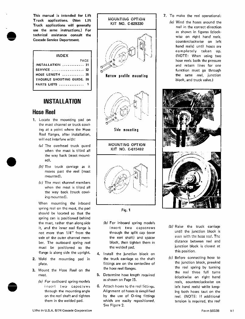
MOUNTING OPTION KIT NO. C-629330
Harrow profile mounling
Side mounling
MOUNTING OPTION KIT NO. C-615492
Fig. 1
(b) For inboard spring models
insert two capscrews
through the split cap (over
the reel shaft) and spacer
block, then tighten them in
the welded pad.
4. Install the junction block on
the truck carriage so the shaft
fittings are on the centerline of
the hose reel flanges.
5. Determine hose length required
as shown on Page 15.
6. Attach hoses to the reel fittings.
Alignment of hoses is simplified
by the use of O-ring fittings
which are easily repositioned. See Figure 2.
7. To make the reel operational:
la) Wind the hoses around the
reel in the correct direction
as shown in figures (clock-
wise on right hand reels,
counterclockwise on left
hand reels) until hoses are
completely taken up.
(NOTE: When using two
hose reels both the pressure
and return lines for one
function must go through
the same reel, junction
block, and truck valve.)
(b) Raise the truck carriage
until the junction block is
even with the hose reel. The
distance between reel and
junction block is closest at
this position.
(c) Before connecting hose to
the junction block, prewind
the reel spring by turning
the reel three full turns
(clockwise on right hand
reels, counterclockwise on
left hand reels) while keep-
ing both hoses taut on the
reel. (NOTE: If additional
tension is required, the reel
Form 5033B I-1
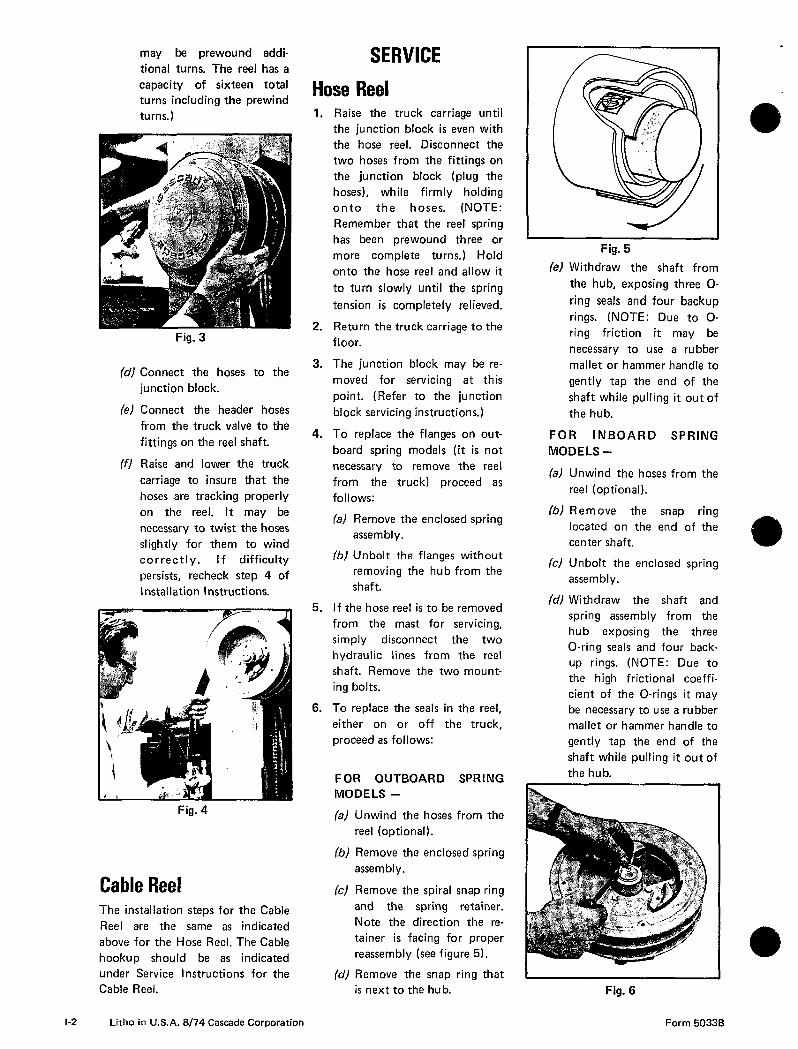
may be prewound addi-
tional turns. The reel has a
capacity of sixteen total
turns including the prewind
turns.)
Fig. 3
(d) Connect the hoses to the
junction block.
(e) Connect the header hoses
from the truck valve to the
fittings on the reel shaft.
(f) Raise and lower the truck
carriage to insure that the
hoses are tracking properly
on the reel. It may be
necessary to twist the hoses
slightly for them to wind
correctly. If difficulty
persists, recheck step 4 of
Installation Instructions.
Fig. 4
Cable Reel The installation steps for the Cable
Reel are the same as indicated
above for the Hose Reel. The Cable
hookup should be as indicated
under Service Instructions for the
Cable Reel.
l-2 Litho in U.S.A. 8/74 Cascade Corporation
SERVICE
Hose Reel 1. Raise the truck carriage until
the junction block is even with
the hose reel. Disconnect the
two hoses from the fittings on
the junction block (plug the
hoses), while firmly holding
onto the hoses. (NOTE:
Remember that the reel spring
has been prewound three or
more complete turns.) Hold
onto the hose reel and allow it
to turn slowly until the spring
tension is completely relieved.
2. Return the truck carriage to the
floor.
3. The junction block may be re-
moved for servicing at this
point. (Refer to the junction
block servicing instructions.)
4. To replace the flanges on out-
board spring models (it is not
necessary to remove the reel
from the truck) proceed as
follows:
(a) Remove the enclosed spring
assembly.
(b) Unbolt the flanges without
removing the hub from the
shaft.
5. If the hose reel is to be removed
from the mast for servicing,
simply disconnect the two
hydraulic lines from the reel
shaft. Remove the two mount-
ing bolts.
6. To replace the seals in the reel,
either on or off the truck,
proceed as follows:
FOR OUTBOARD SPRING
MODELS -
(a) Unwind the hoses from the
reel (optional).
(b) Remove the enclosed spring
assembly.
(c) Remove the spiral snap ring
and the spring retainer.
Note the direction the re-
tainer is facing for proper
reassembly (see figure 5).
(d) Remove the snap ring that is next to the hub.
Fig. 5
(e) Withdraw the shaft from
the hub, exposing three O-
ring seals and four backup
rings. (NOTE: Due to O-
ring friction it may be
necessary to use a rubber
mallet or hammer handle to
gently tap the end of the
shaft while pulling it out of
the hub.
FOR INBOARD SPRING
MODELS -
(al Unwind the hoses from the
reel (optional).
(b) Remove the snap ring
located on the end of the
center shaft.
(c) Unbolt the enclosed spring
assembly.
(d) Withdraw the shaft and
spring assembly from the
hub exposing the three
O-ring seals and four back-
up rings. (NOTE: Due to
the high frictional coeffi-
cient of the O-rings it may
be necessary to use a rubber
mallet or hammer handle to
gently tap the end of the
shaft while pulling it out of
the hub.
Fig. 6
Form 5033B

7. Before removing the O-rings
and backup rings, carefully note
their positions in the grooves on
the shaft.
8. Cascade recommends the in-
stallation of a complete set of
new seals whenever one seal
requires replacement. Use only
Cascade approved parts.
9. Check the following areas when
servicing your hose reel seals:
(a) The sealing surface where
the O-ring is seated in the
hub must be smooth.
Rough areas cause prema-
ture wear and early leakage.
Replace if necessary.
(b) Shaft grooves must be free
of sharp nicks or projec-
tions to prevent cutting of
the inside diameter of the
O-ring during installation.
(c) Excessive stretching of the
O-ring when installed can
cause permanent distortion.
An O-ring may be stretched
no more than 25 percent of
its diameter.
(d) Installation of backup rings
in their proper locations is
essential. Refer to the parts
illustrations in this manual
for reference.
(e) If the O-ring seal nearest the
spring assembly was dam-
aged and allowed hydraulic
oil to leak into the spring
can, drain the spring can
before reassembly. If ex-
cessive oil is left in the
spring assembly, it will seep
out after reassembly and
appear as though there is a
serious oil leak.
(f) Clean all components with a
non corrosive solvent before
reassembly.
Apply a liberal amount of pe-
troleum jelly or hydraulic oil
(STP) to the seals, shaft, and
the interior of the hub before
reassembling. Rotate the hub
slowly as you push it onto the
shaft. This will prevent damage
to the seals and make reas-
sembly easier.
10. No further disassembly of out-
board spring models is required.
11. For further disassembly of in-
board spring models proceed as
follows:
(a) Remove snap ring that is
next to the enclosed spring
assembly.
(b) Pull the spring can off the
shaft, being careful not to
damage the O-ring grooves.
Nicks on the shaft grooves
will cause excessive wear on
the sealing parts.
(c) To replace felt seal on the
shaft, remove the old one,
clean the metal surface and
apply contact cement to the
shaft and the new seal. Posi-
tion new seal on the shaft.
Fig. 7
12. As a general rule, the Enclosed
Spring Assembly should be
lubricated with Moly Lube or
the equivalent once every six
months.
13. To reassemble your Cascade
hose reel reverse the above
steps. Refer to parts illustra-
tions in this manual for further
assistance. (NOTE: Be sure
spring retainer is facing in
proper direction to engage
spring, See Figure 8.)
Junction Block 1. Raise the truck carriage until
the junction block is even with
the hose reel. Disconnect the
two hoses from the fittings on
the junction block while firmly
holding onto the hoses. (NOTE:
Remember that the reel spring
Fig. 8
has been prewound three com-
plete turns.) Hold onto the hose
reel and allow it to turn slowly
until the spring tension is com-
pletely relieved.
2. Return the truck carriage to the
floor.
3. Remove the junction block
from the truck carriage by
loosening the capscrew or cap-
screws which hold the block to
the carriage.
4. Remove the snap ring retainer
from the end of the shaft.
5. Pull the shaft out of the body
of the junction block. This will
expose the O-rings and backup
rings.
6. Before removing the O-rings
and backup rings, carefully note
their position in the grooves on
the shaft.
7. Replace the worn seals with
Cascade approved components.
All the O-rings and backup rings
should be replaced at the same
time.
8. Check the following areas when
servicing junction block seals:
(a) The sealing surface where
the O-ring is seated in the
body must be smooth.
Rough areas cause prema-
ture wear and early leakage.
(b) Shaft grooves must be free
of sharp nicks or projec-
tions to prevent cutting of
the inside diameter of the
O-ring during installation.
(c) Excessive stretching of the
O-ring when installed can
cause permanent distortion.
Litho in U.S.A. 8/74 Cascade Corporation Form 50338 l-3

An O-ring may be stretched
no more than 25 percent of
its diameter.
(d) Installation of backup rings
in their proper location is
essential. Refer to the parts
illustrations in the manual
for reference.
(e) If your junction block is
equipped with integral
check valves, inspect the
balls and ball guides for
excessive wear. Examine the
interior surface of the body
for smoothness.
(f) Clean all components with a
non corrosive solvent before
reassembly.
9. Apply a liberal amount of pe-
troleum jelly or hydraulic oil
(STP) to the seals, shaft, and
junction block body before re-
assembly.
10. In reassembly, rotate the shaft
slowly into the body of the
block to prevent damage to the seals.
11. Replace the snap ring and re-
turn the unit to the truck car- riage.
Cable Reel NOTE: Cable reel must be removed
from truck for servicing.
1. Raise truck carriage until junc-
tion block is even with reel.
Unplug connection to solenoid
valve and unbolt junction block
from carriage. CAUTION: Hold
onto reel and slowly allow reel
to turn until all spring tension is
removed.
2. Remove reel from truck.
3. Unwind cable from reel and remove wire from terminals. Be
sure to note which color goes to
each terminal. This will save
you time later.
4. Unbolt and remove enclosed
spring assembly.
5. Unbolt then remove hub and
shaft assembly.
6. TO SERVICE BRUSHES AND
l-4 Litho in U.S.A. 8/74 Cascade Corporation
w Fig. 9
BRUSH HOLDERS proceed as
follows:
(a) Loosen setscrews in the hub
that secure the brush hold-
ers.
(b) Remove brush holders from
hub.
(c) Remove brush from holder.
(d) Inspect brush for wear and
replace when length of con-
tact is down to 3/16” or
1/4”.
(e) The collector rings may be
serviced at this point
(Refer to the collector ring
servicing instructions, step
No. 8.1
7. To reinstall the brushes and
brush holders it is necessary to
have the hub and shaft as-
sembled. Proceed as follows:
(a) Reinstall terminal cap on
holder if previously re-
moved.
(b) Reinsert brush in brush
holder through bottom,
spring end first.
(c) Make sure brush is in proper
position in relation to col-
lector ring then reinsert
brush and holder into hub.
(d) While pressing the brush
holder firmly in place
tighten setscrew.
8. TO SERVICE COLLECTOR
RINGS complete steps 1
through 6 first then proceed as
follows: (NOTE: If the col-
lector rings need replacement
see step No. 10.)
(a) Remove spiral snap ring and
spring retainer.
(b) Remove felt seal from slot.
(c) Remove snap ring and wash-
er.
(d) Pull shaft from hub.
(e) Clean collector rings.
(NOTE: Do not leave any
residue on insulators be-
tween collector rings.)
CAUTION: Do not use any
abrasive on the two oilite
bearings.
9. Reassemble shaft in hub as-
sembly. CAUTION: Make sure
the felt seal is installed in its
original folded position. This
seals all electrical components
from the spring assembly lubri-
cation.
10. TO REPLACE COLLECTOR
RINGS proceed as follows:
(a) Remove snap ring holding
90 degree electrical con-
nector in end of shaft.
(b) Pull connector and retainer
out the shaft.
(c) Disconnect wires by holding
connector and separating
coupling from interior
wires.
(d) Remove outer oilite bearing
and slide collector rings
toward end of shaft while
feeding wire up through slot
in shaft from inside. CAU-
TION: Note the sequence
of wire colors when remov-
ing rings so that they will be
replaced in the same order.
Form 50338
(e) To reassemble reverse the
above procedures. Care
should be exercised when
installing collector rings on
shaft so that wires and
positioning lugs are not
damaged or dislodged from
collector rings.
11. As a general rule, the Enclosed
Spring Assembly should be
lubricated with Moly-Lube or
the equivalent once every six
months.
COLOR CODING OF WIRES
TWO FUNCTION APPLICATION
Green-Ground
White-Energize
NOTE: Cover brush cap terminals Black-Cut off (not used)
with sealant (Part No. C-650000) THREE FUNCTION APPLICA-
provided after cable is mounted on TION
reel. Green-Ground
White-Energize
*Black-Energize
*Black is always Sideshift or
rotate function. White is other
function.
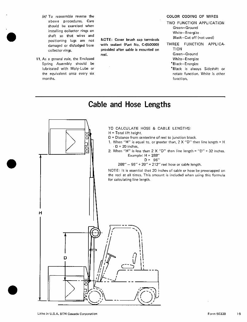
Cable and Hose Lengths
T- D
TO CALCULATE HOSE & CABLE LENGTHS:
H = Total lift height.
D = Distance from centerline of reel to junction block.
1. When “H” is equal to, or greater than, 2 X “D” then line length = H
- D + 20 inches.
2. When “H” is less than 2 X “D” then line length = “D” + 32 inches.
Example: H = 288”
D = 96”
288” - 96” + 20” = 212” reel hose or cable length.
NOTE: It is essential that 20 inches of cable or hose be prewrapped on
the reel at all times. This amount is included when using this formula
for calculating line length.
Litho in U.S.A. 8/74 Cascade Corporation Form 50336 l-5

Typical Hose and Cable Reel Installation
Note direction of rotation on nameplate
7
PLAN VIEW
Max clearance X” between reel flange and mast channel,
Hose Reel, R.H. (Includes Junction Block)
I To determine length refer to hose 81 cable
uck
I
length slve formulas
Header Hose
x To $$y
Solenoid Valve
El
Junction Block)
Header Cable
t-t
b Cable Reel Junction Block
r-y--
/ \ J FRONT VIEW
SIDE VIEW
l-6 Litho in U.S.A. B/74 Cascade Corporation Form 5033B
PROBLEM a Hose Reel leaks at
hub.
Excessive wear on
hoses.
Hose jumping off of
reel in reeling ac-
tion.
Binding of hose reel
winding action.
Junction block leak.
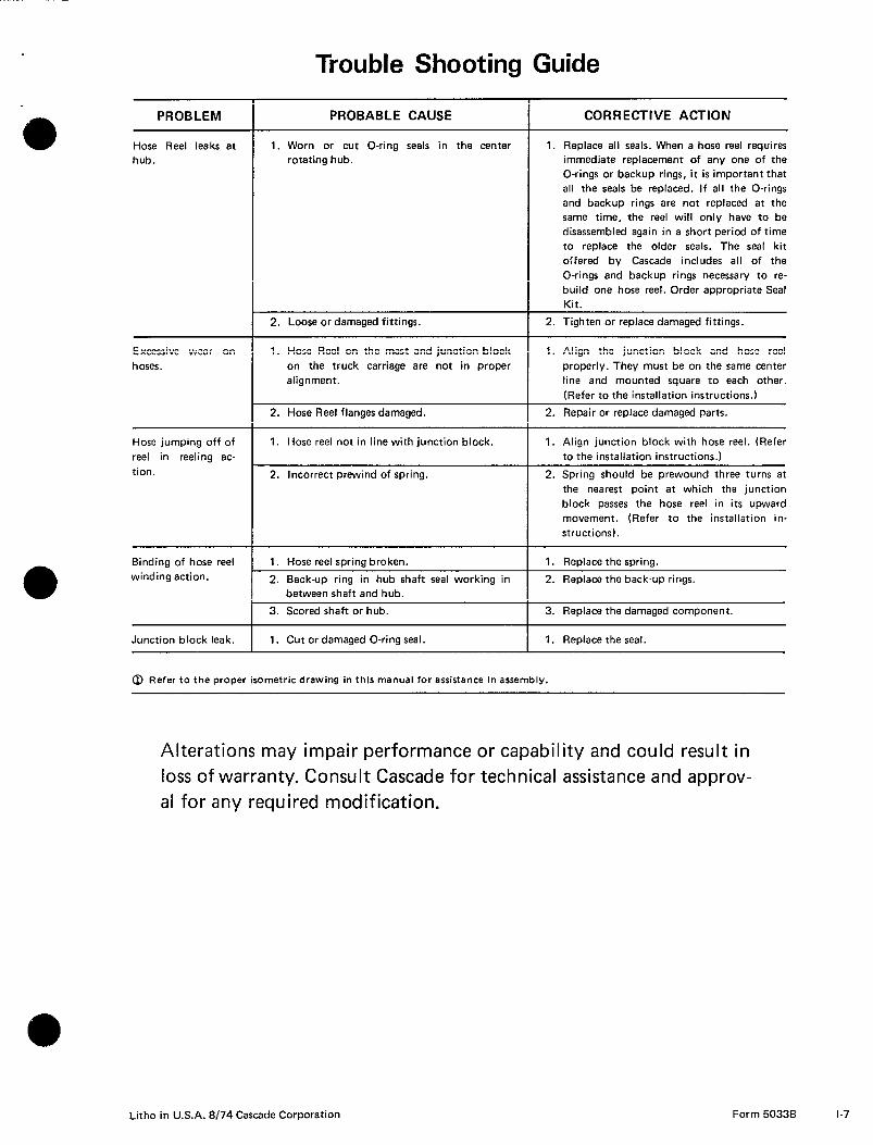
Trouble Shooting Guide
PROBABLE CAUSE
1. Worn or cut O-ring seals in the center
rotating hub.
2. Loose or damaged fittings.
1. Hose Reel on the mast and junction block
on the truck carriage are not in proper
alignment.
2. Hose Reel flanges damaged.
1. Hose reel not in line with junction block.
2. Incorrect prewind of spring.
1. Hose reel spring broken.
2. Back-up ring in hub shaft seal working in
between shaft and hub.
3. Scored shaft or hub.
1. Cut or damaged O-ring seal.
0 Refer to the proper isometric drawing in this manual for assistance in assembly.
CORRECTIVE ACTION
1. Replace all seals. When a hose reel requires
immediate replacement of any one of the
O-rings or backup rings, it is important that
all the seals be replaced. If all the O-rings
and backup rings are not replaced at the
same time, the reel will only have to be
disassembled again in a short period of time
to replace the older seals. The seal kit
offered by Cascade includes all of the
O-rings and backup rings necessary to re-
build one hose reel. Order appropriate Seal
Kit.
2. Tighten or replace damaged fittings.
1. Align the junction block and hose reel
properly. They must be on the same center
line and mounted square to each other.
(Refer to the installation instructions.)
2. Repair or replace damaged parts.
1. Align junction block with hose reel. (Refer
to the installation instructions.)
2. Spring should be prewound three turns at
the nearest point at which the junction
block passes the hose reel in its upward
movement. (Refer to the installation in-
structions).
1. Replace the spring.
2. Replace the back-up rings.
3. Replace the damaged component.
1. Replace the seal.
Alterations may impair performance or capability and could result in
loss of warranty. Consult Cascade for technical assistance and approv-
al for any required modification.
Litho in U.S.A. 8/74 Cascade Corporation Form 50338
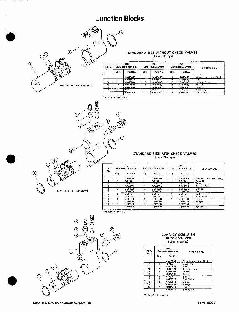
Junction Blocks
,
Complete Junction Block C-646057 C-646058
STANDARD SIZE WITHOUT CHECK VALVES (Less Fittings)
C-646059
VT HAND SHOWN
J3A Right Hand Mounting
OW. Pen No.
J3L J3C Left Hand Mounting Or&enter Mounring
my. Pert. No. w. Pan No.
DESCRIPTION
‘Included in Service Kit
C-646340 C-646340 C-646340 Service Kit
STANDARD SIZE WITH CHECK VALVES (Less Fittings)
C-646056 C-646055 C-646054 Complete Junction Block
JZC JZL JZR REF. On-Center Mounting Left Hand Mounting Right Hand Mounting DESCRIPTION
tltv. Pan No. my. Part No. CHV. Part No.
ON CENTER SHOWN
d in Service Kit
C-646340 C-646340 C-646340 Service Kit
COMPACT SIZE WITH CHECK VALVES
(Less Fittings)
C-610838 Complete Junction Block
‘Included in Service Kit
C-615940 Service Kit
Litho in U.S.A. 8/74 Cascade Corporation Form 50336 1
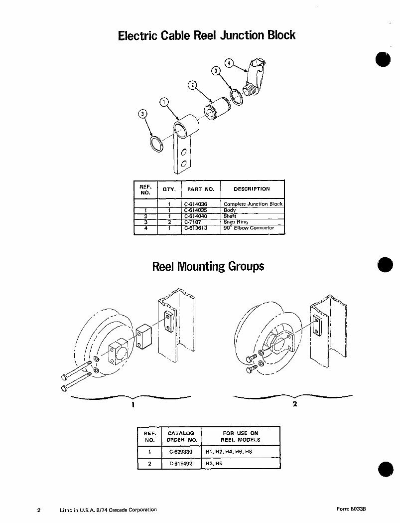
Electric Cable Reel Junction Block
1 “NEO’.’ 1 QTY. ( PART NO. ( DESCRIPTION I
C-614036 Complete Junction Block
Reel Mounting Groups
A
2
C-629330
C-615492
2 Litho in U.S.A. 8/74 Cascade Corporation

Fitting Groups
C-646063 C-646062 C-646061
HOSE REEL FITTING GROUPS
H1, H2, H4, H6, H8 INBOARD SPRING MODELS
Each group includes four straight O-Ring connectors and two Swivel
90’ Elbows. This permits hose connections into and out of the Hose Reel.
I H3, H5 OUTBOARD SPRING MODELS I
I CATALOG
ORDER NO. I HOSE SIZE
I
C-646308 No. 5
C-646307 No. 6 C-646306 No. 8
Each group includes three straight O-Ring connectors, one 90°
O-Ring Elbow and one 90’ Swivel Elbow. This permits hose connections into and out of the Hose Reel.
JUNCTION BLOCK FITTING GROUPS
J1C JUNCTION BLOCK
CATALOG
ORDER NO. HOSE SIZE
C-646375 No. 5 C-646374 No. 6 C-646376 No. 8
J2 AND J3 JUNCTION BLOCKS
C-646319 No. 5
C-646318 No. 6
C-646319 No. 8
Four straight connectors are furnished. This permits hose connections into and out of the Junction Block.
Litho in U.S.A. 8/74 Cascade Corporation Form 50338 3
Lith
o
in
U.S
.A.
8/74 C
ascade
Co
rpo
ration
F
orm
5033B
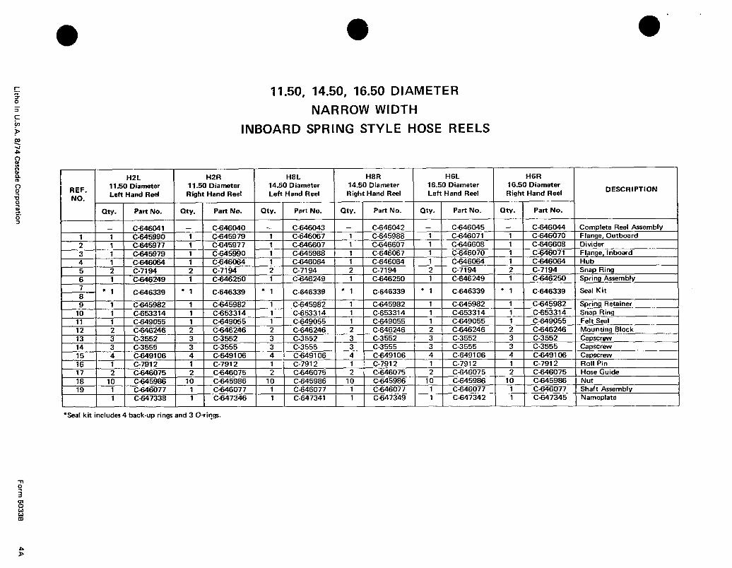
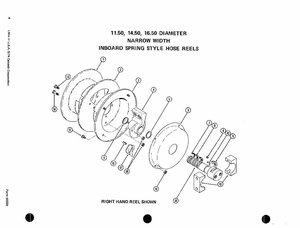
11.50, 14.50, 16.50 DIAMETER
NARROW WIDTH
INBOARD SPRING STYLE HOSE REELS
C-646339 C-646339 C-646339 C-646339 C-646339
C-646041 C-646040 C-646043 C-646042 C-646045 C-646044 Complete Reel Assembly
16.50 Diameter
Left Hand Reel
16.50 Diameter DESCRIPTION
Seal Kit
l Saal kit includes 4 back-up rings and 3 O-rings.

II W
5 L
itho
in
U.S
.A.
8174 C
ascade
Co
rpo
ration
F
orm
50336
C-646339 C-646339 C-646339 Seal Kit
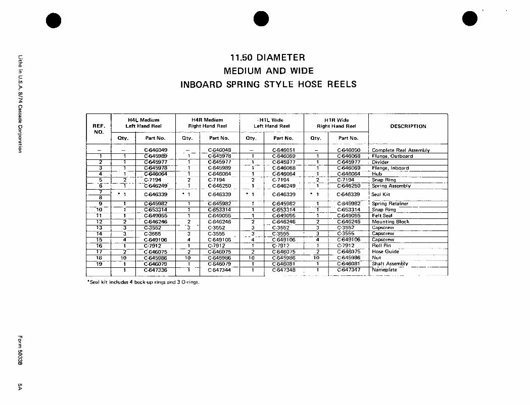
C-646049
11.50 DIAMETER
MEDIUM AND WIDE
INBOARD SPRING STYLE HOSE REELS
C-646048 C-646051 C-646050 Complete Reel Assembly
REF.
NO.
H4L Medium H4R Medium
Left Hand Reel Right Hand Reel
my. Part No. my. Part No.
s HIL Wide Left Hand Reel
my. Part No.
HlR Wide Right Hand Reel
my. Part No.
DESCRIPTION
- 1 C-646339 * 1
a I 1 1 r-.GAW3X7
I I
1; I ; - ----
I c-649055 I
t f
14 I : - ---- I 3 I c-3555
I
t i; 1 - .--- 1
i 1 C-646075 1
*Seal kit includes 4 back-up rings and 3 O-rings.
t
6 L
itho
in
U.S
.A.
8/74 C
ascade
Co
rpo
ration
F
orm
50338
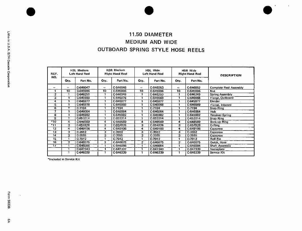
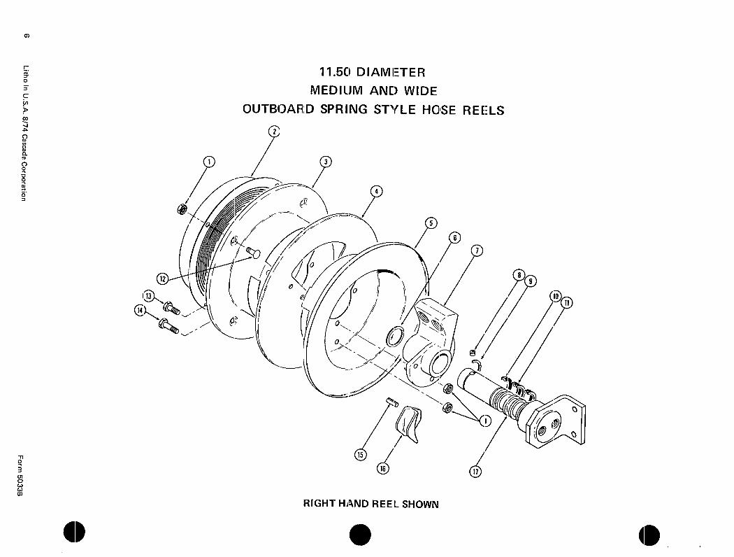
11.50 DIAMETER
MEDIUM AND WIDE
OUTBOARD SPRING STYLE HOSE REELS
C-646047 C-646046 C-646053 C-646052 Complete Reel Assembly
I H3L Medium I H3R Medium I H5L Wide I H5R Wide I REF. NO.
Left Hand Reel Right Hand Reel Left Hand Reel Right Hand Reel DESCRIPTION
*Included in Service Kit
C-646339 C-646339 C-646339 C-646339 Service KIt
7 L
itho
in U
.S.A
. 8/74
Cascad
e Co
rpo
ration
F
orm
50338
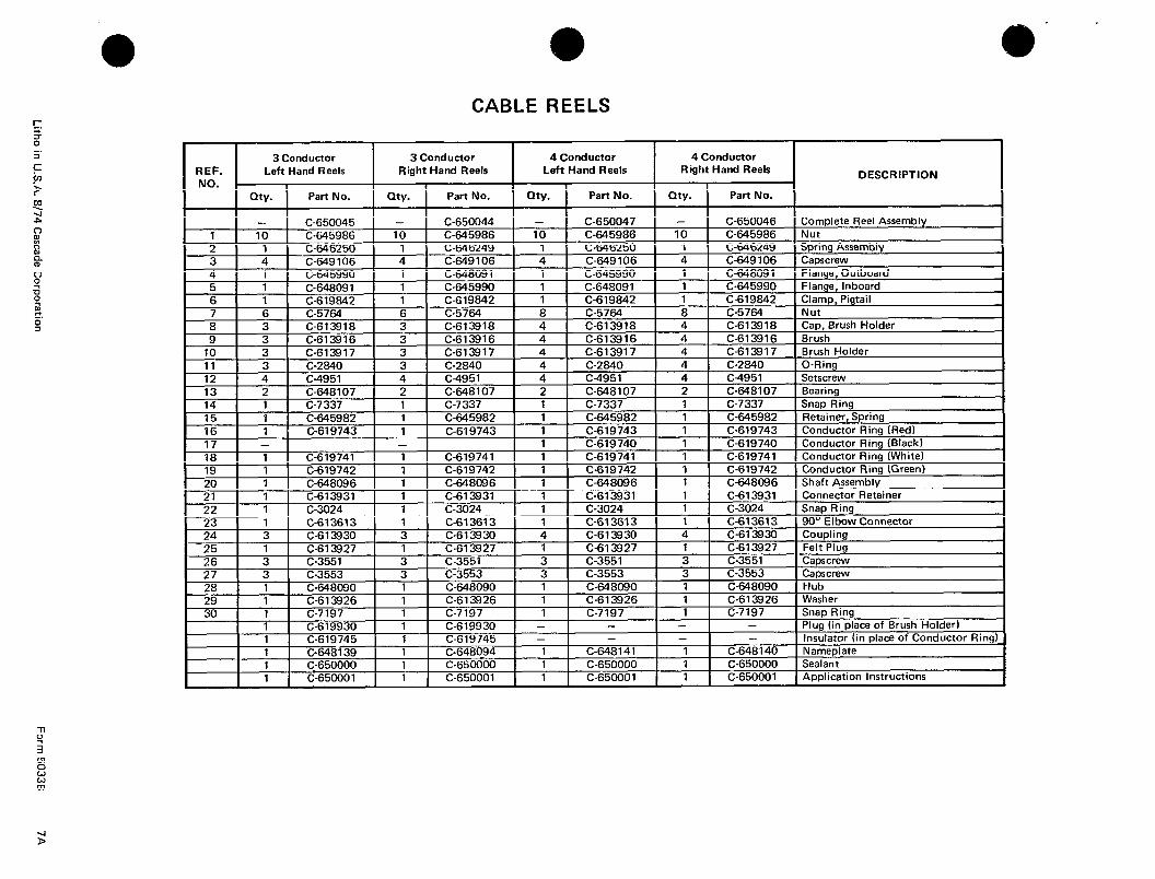
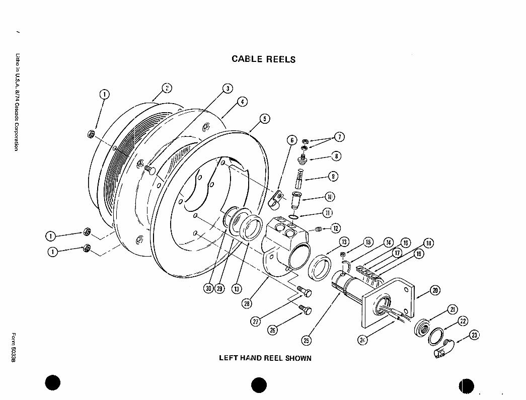
a CABLE REELS
3 Conductor 3 Conductor 4 Conductor 4 Conductor
REF. Left Hand Reels Right Hand Reels Left Hand Reels Right Hand Reels DESCRIPTION
NO. _ 1 I I I my. Part No. my.
t t
Part No. my. Part No. my. Part No. I I
C-650045 - 1 IO C-645986 10 1 2 1 C-646250 1 - I c-Wf=l?
3 4 C-649 106 4 A ‘1 rXAlxmrl 1 t
1 C-650044 C-650047 - 1 C-650046j Complete Reel Assembly
C-645986 IO - -...--- iA!iR8~ Nut rn , r-cnc-lcn 1 Cr...;..” Arrmnhl\r
--+- t ” “7”““”
a-!.F.ARnrll I , ” - . - ” - .
i 1 i 1 C-619842 7 I C-G I PJt7c.a I G t
I 1
I “I RI RI f--s---
3
I v-x,-.- .“”
, C-648091
c-645990 C-619842
, c-5764 1 C-613918
I C-613916
.- - - - - - -
--.---Pa , , ~.-vr”L4J 1 C-646249 , v,.sn “my r..,.menuuus, r-CAO,r-,‘Z I A I C-649,(,6 4 C-649106 I ccwlcfvlaw 1
C-645990 1 C-648m t P cnong, 1 c-645,,,
” ” ..#&I2 1 C-619842 c!.67KA 8 wi7M
, ““r”“..,..
-- . Flange, Outboard
b-“-?o”i .ooq Flange, Inboard r-.Rlo*. ! Clamp. Pigtail - “.“. - -.-. Nut C-613918 1
4 1 C-613918 Cap, Brush Holder
C-613916 1 4 i C-613916 Brush
12 4 c-L--. 13 2 C-648107 1 2 C-648107 1 2 i I 14 1 C-7337 I 1
15 1 c-64--- , 16 1 C-619743 1 17 - 1 1 1 , 18 1 C-619741 1 C-619741 1 1 1 C-619741 I
19 1 C-619742 1 7” 1 1
t ;i _ -.-_-.
I I C-3024 I
I
1 ;Ei I - - -- - -
; I C-613927 i
28 I I 1 1 c-64 ---
70 I 1 I C-Rl?q7G I 1
Do you have questions you need answered right now? Call your nearest Cascade Parts Department.
Cascade Corporation 2201 NE 201st Troutdale, OR 97060 Tel: 1-800-CAS-CADE
503-669-6300 FAX: 503-669-6338
Cascade N.V. European Headquarters P.O. Box 50086 1305 AB Almere-Haven Achterwerf 240 1357 CB Almere-Haven The Netherlands Tel: 31-36-5392911 FAX: 31-36-5314223
Cascade France S.A.R.L. 11, Rue Jean Charcot Zone lndustrielle Sud or B.P. 22 91421 Morangis Cedex France Tel: 1-64547500 FAX: 1-64547501
HYCO-Cascade Pty. Ltd. 87 Antimony Street Carole Park, Brisbane 4300 Australia Tel: 7-271-1966 FAX: 7-271-3830
Sunstream Industries PTE Ltd. No. 3 Tuas Link 1 Singapore 2263 Tel: 863-3488 FAX: 863- 1368
0 Cascade Corporation 1974
Cascade Canada Inc. 5570 Timberlea Blvd. Mississauga, Ontario Canada L4W-4M6 Tel: 905-629-7777 FAX: 905-629-7785
Cascade N.V. Benelux Sales and Service P.O. Box 50086 1305 AB Almere-Haven Achterwerf 240 1357 CB Almere-Haven The Netherlands Tel: 31-3653-92980 FAX: 31-3653-13907
Cascade Hispania S.A. Avenida De La Fabregada, 7 Hospitalet De Llobregat Barcelona Spain Tel: 3-335-5158 FAX: 3-335-4756
HYCO-Cascade (NZ) Ltd. 23 Haseler Cresent PC. Box 38-440 Howick, Auckland New Zealand Tel: 9-273-9136 FAX: 9-273-9137
Xiamen-Cascade Corp. Ltd. 883 Xiahe Road Xiamen, Fujian, PRC Tel: 592-556548 FAX: 592-5056348
Cascade GmbH D-41 199 Monchengladbach Klosterhofweg 52 Germany Tel: 21-66-602091 FAX: 21-66-680947
Cascade (UK) Ltd. 15, Orgreave Crescent Dore House Industrial Estate Handsworth Sheffield S13 9NQ England Tel: 742-697524 FAX: 742-695121
Cascade Japan Ltd. 5-5-41, Torikai Kami Settsu, Osaka Japan, 566 Tel: 81-726-53-3490 FAX: 81-726-53-3497
Cascade (Africa) Pty. Ltd. P-0. Box 625, lsando 1600 60A Steel Road Sparton, Kempton Park South Africa Tel: 975-9240 FAX: 394-1147
8-74
Cascade N.V. Kirkkokatu 1 48100 Kotka Finland Tel: 52-184393 FAX: 52-184833
Cascade Scandinavia Hydraulik A.B. Musktitgatan 19, E8-9 S25466 Helsingborg Sweden Tel: 42-151135 FAX: 42-152997
Equipamentos Para Movlmentacao de Materials LTDA Rua Lopes Chaves, 380 Sao Paula, 01154, S.P., Brazil Tel: 118-250099 FAX: 11-66-0340
Cascade Korea Room 508, Pum Yang Bldg. 750-14, Bang Bat-Dong Se-Cho Ku, Seoul Korea Tel: 2599-7131 ext. 512 FAX: 2533-8089
Part Number 667407 Rev. 0


