217
PassageWay Telephony Services for Windows NT Release 2.22 DEFINITY Enterprise Communications Server Simulator User’s Guide Issue 3.1

PassageWay TelephonyServices for Windows NT
Release 2.22
DEFINITY EnterpriseCommunications ServerSimulator User’s GuideIssue 3.1

3.1
Copyright 1997 Lucent Technologies Inc.All Rights ReservedPrinted in U.S.A.
NoticeWhile reasonable efforts were made to ensure that the information in this document was complete andaccurate at the time of printing, Lucent Technologies assumes no responsibility for any errors orliability for any direct or consequential damages resulting from use of the information. Changes andcorrections to the information contained in this document may be incorporated into future reissues.
Your Responsibility for Your System’s SecurityToll fraud is the unauthorized use of your telecommunications system by an unauthorized party, forexample, persons other than your company’s employees, agents, subcontractors, or persons workingon your company’s behalf. Note that there may be a risk of toll fraud associated with yourtelecommunications system and, if toll fraud occurs, it can result in substantial additional charges foryour telecommunications services.
You and your system manager are responsible for the security of your system, such as programmingand configuring your equipment to prevent unauthorized use. The system manager is alsoresponsible for reading all installation, instruction, and system administration documents provided withthis product in order to fully understand the features that can introduce risk of toll fraud and the stepsthat can be taken to reduce that risk. Lucent Technologies does not warrant that this product isimmune from or will prevent unauthorized use of common-carrier telecommunication services orfacilities accessed through or connected to it. Lucent Technologies will not be responsible for anycharges that result from such unauthorized use.
TrademarksMicrosoft, DOS, Windows, Windows NT and the Microsoft logotype are registered trademarks of
Microsoft Corp.PassageWay, CallVisor, DEFINITY, and the Lucent Technologies logotype are registered trademarks
of Lucent Technologies.
The following abbreviations and conventions are often used in this document: "DEFINITY Generic 3" or"Generic 3" for DEFINITY Communications System Generic 3, and "G3PD" for the DEFINITY Generic 3PBX Driver. The terms "PBX" and "switch" are used interchangeably to mean "private branchexchange".
AcknowledgmentThis document was prepared by the Business Communications Systems Product DocumentationDevelopment Group, Lucent Technologies, Middletown, NJ 07748-1998.

DEFINITY ECS Simulator User‘s Guide Issue 3.1 January 1997 iii
Contents
Chapter 1—Simulator Overview
Introduction 1-1Simulator Environment 1-3The Client Simulator 1-3Output Display 1-4Message Input 1-4Simulation Status 1-4Configuration Files 1-4Client Simulator Status 1-5
The Simulator DLL 1-6The Simulator Console Interface 1-6Simulator Operation 1-7Differences Between the Simulator and the DEFINITY PBX 1-8
Chapter 2—Using the Simulator
Installation Overview 2-1Installing the Simulator 2-1Configuring the Simulator 2-2Loading the Simulator 2-2Testing the Application 2-3Establishing a Simulator Session at the Client Simulator 2-3Establishing an Exerciser Session at the Client Simulator 2-5Closing the Session at the Client Simulator 2-7Message Tracing at the Client Simulator 2-7Simulating Manual Operations 2-8Using the Simulator Console Interface 2-11Main Dialog Box 2-13Active Calls Button 2-14Connections Tab 2-15UUI Tab 2-17Routing Tab 2-19UEC Tab 2-20OCI Tab 2-23

iv January 1997 Issue 3.1 DEFINITY ECS Simulator User‘s Guide
Devices Button 2-25Monitors Button 2-36Sessions Button 2-37Settings Button 2-39Close Button 2-41About SimCons Box 2-41
Chapter 3—Configuration Files
Introduction 3-1The File Menu 3-2The Admin Menu 3-3System Parameters 3-4Manual Digit Collection 3-5First Digit Table 3-6Stations 3-8Trunk Groups 3-16ACDs 3-19
Simulator Capacities 3-23Saving Configuration File(s) 3-23
Chapter 4—Sending Messages to the Simulator DLL
Introduction 4-1Functions - Call Control Services 4-2Alternate Call 4-3Answer Call 4-5Call Completion 4-6Clear Call 4-7Clear Connection 4-8Conference Call 4-11Consultation Call 4-13Deflect Call 4-16Group Pickup Call 4-17Hold Call 4-18Make Call 4-19Make Predictive Call 4-22Pickup Call 4-25Reconnect Call 4-26Retrieve Call 4-29Transfer Call 4-30

DEFINITY ECS Simulator User‘s Guide Issue 3.1 January 1997 v
Send DTMF Tone 4-32
Functions - Escape Services 4-34Escape Service 4-35Escape Service Confirmation 4-37Send Private Event 4-38
Functions - Maintenance Services 4-39Change System Status Filter 4-40System Status Request 4-41System Status Start 4-42System Status Stop 4-44System Status Event Send 4-45System Status Request Confirmation 4-46System Status Filtering 4-47
Functions - Query Services 4-48Get API Capabilities 4-49Get Device List 4-50Query Call Monitor 4-52Query Agent State 4-53Query Device Information 4-55Query Do Not Disturb 4-56Query Forwarding 4-57Query Last Number 4-58Query Message Waiting Indicator 4-59Query ACD Split 4-60Query Agent Login 4-61Query Call Classifier 4-62Query Device Name 4-63Query Station Status 4-64Query Time of Day 4-65Query Trunk Group 4-66
Functions - Routing Services 4-67Route System Parameters 4-68Route Tables (Automatic Routing Feature) 4-69Manual Routing Dialog 4-74Route End 4-76Route Register Cancel 4-77Route Register 4-78Route Select 4-79
Functions - Set Feature Services 4-83Set Agent State 4-84Set Do Not Disturb 4-86Set Forwarding 4-87Set Message Waiting Indicator 4-89

vi January 1997 Issue 3.1 DEFINITY ECS Simulator User‘s Guide
Functions - Snapshot Services 4-90Snapshot Call 4-91Snapshot Device 4-92
Functions - Status Reporting Services 4-93Change Monitor Filter 4-94Monitor Call 4-95Monitor Calls Via Device 4-96Monitor Device 4-97Monitor Stop 4-98Monitor Stop on Call 4-99Filter Selection 4-100
PBX Menu 4-102Off-hook 4-103On-hook 4-104In-bound Calls 4-105Finish Monitor 4-106Route End 4-107Disable Link 4-108Enable Link 4-109
Simulator Menu 4-110Change Device Parameters 4-111Query Device 4-112Query Call 4-113Query All Active Calls 4-114Query All Stations 4-115Query All Trunk Groups 4-116Query All ACD Groups 4-117Query All Monitors 4-118Enable/Disable Tracing 4-119
Help Menu 4-120

DEFINITY ECS Simulator User‘s Guide Issue 3.1 January 1997 1-i
Chapter 1—Simulator Overview
Introduction 1-1Simulator Environment 1-3The Client Simulator 1-3Output Display 1-4Message Input 1-4Simulation Status 1-4Configuration Files 1-4Client Simulator Status 1-5
The Simulator DLL 1-6The Simulator Console Interface 1-6Simulator Operation 1-7Differences Between the Simulator and the DEFINITY PBX 1-8


Simulator Overview
1
DEFINITY ECS Simulator User‘s Guide Issue 3.1 January 1997 1-1
Introduction
The purpose of the Lucent PBX Simulator is to provide a DEFINITY switch environment forpreliminary software development of applications using the Telephony Services Release 2 forWindows NT® product. This document assumes a basic knowledge of both Windows NT andTelephony Services.
The Lucent PBX Simulator is a functional subset of the DEFINITY Enterprise CommunicationsServer (ECS) PBX environment in that it cannot simulate the full range of possible scenarios thatcan be encountered on a PBX. The Simulator does allow an application developer to issue mostof the commands available in the Telephony Services Release 2 for Windows NT product. (Seethe Passageway Telephony Services for Windows NT Release 2 DEFINITY System Programmer’sGuide for specific information.)
NOTE:Complete testing of any application can only be accomplished on a PBX. TheSimulator is not a substitute for final testing of all features on an actual PBX.
The DEFINITY Simulator (hereafter referred to as the Simulator) simulates the DEFINITY G3 PBXDriver (hereafter referred to as the PBX Driver) and the DEFINITY PBX that stands behind it inthe Telephony Services Release 2 for Windows NT product. As such, the PBX Simulator:
• registers with the Telephony Server as a PBX Driver would register;• accepts and processes CSTA requests from an application using the Telephony Services
API (see the Telephony Services Application Programming Interface (TSAPI) Version 2 andthe Passageway Telephony Services for Windows NT DEFINITY System Programmer’sGuide); and
• returns confirmation and asynchronous events, as if the application were running with aDEFINITY PBX with the DEFINITY PBX Driver.

Simulator Overview
1-2 January 1997 Issue 3.1 DEFINITY ECS Simulator User‘s Guide
For example, if the application issues a make call request between two stations in the Simulatorconfiguration and the stations are administered appropriately (see Chapter 3 for details), thenthe:
• application would receive the appropriate confirmation event from the Simulator indicatingthat the PBX had received the make call request;
• appropriate asynchronous events would be delivered to any monitoring parties as if thereceiving station was alerting; and
• appropriate events would be delivered to any monitoring parties as if the user of thereceiving station went off-hook and answered the call.
The illustration below shows two configurations. The top configuration is the Telephony ServicesRelease 2 for Windows NT product with a PBX and a PBX Driver installed. The bottom figure isthe same configuration with the Simulator replacing the PBX and the PBX Driver.
PBXTelephony Services
for Netware
TSDRV(PBX
Driver)
TelephonyServices
NLM
WindowsClient
ApplicationCSTA RequestsConfirmationsEvents
WindowsClient
Application
CSTAAdver-tizedDriver
CSTA RequestsConfirmationsEvents
Installed Application Environment
G3Telephony Services
for NT
G3PD(PBX
Driver)
TelephonyServices
ASAI
WindowsClient
ApplicationCSTA RequestsConfirmationsEvents
WindowsClient
Application
CSTAAdver-tized
Driver
CSTA RequestsConfirmationsEvents
Installed Application Environment
Telephony Servicesfor NT
G3Simulator
TelephonyServices
WindowsClient
ApplicationCSTA RequestsConfirmationsEvents
SimulatorAdver-tized
Driver
Simulator RequestsConfirmationTrace Information
Simulator Test Environment
ClientSimulatorInterface(ProgramsSimulator
Responses)
SimulatesCSTAmessagesas supportedby DEFINITY G3
The Simulator handles CSTA requests based on current simulated call and device state and alsosimulates some aspects of call control from your (that is, the user’s) viewpoint. You must firstbuild a configuration file that tells the Simulator what stations, trunks, and ACDs to simulate. Thisfile is read in by the Simulator when it is loaded. The configuration of stations, etc., that isspecified in the file is the configuration that the Simulator uses in its simulation.
It is important to note that the configuration file does not specify a specific simulation, but ratherspecifies parameters that dictate how some aspects of call control are simulated. The

Simulator Environment
DEFINITY ECS Simulator User‘s Guide Issue 3.1 January 1997 1-3
configuration file also specifies device attributes that are used to determine how the Simulatorresponds to CSTA requests. How the actual simulation proceeds is then entirely dependent onrequests made by the applications and the Client Simulator. For example, a configuration filedoes not state that station A calls station B. Instead, it defines the stations that are availableand their attributes, so that the application can request that station A call station B. Creating theconfiguration file is analogous to administering the DEFINITY G3 PBX.
The Simulator is capable of processing requests from more than one client concurrently,enabling users to see how their application functions in an environment where multiple clientsare using the Simulator simultaneously, thus mirroring a real application environment.
Simulator Environment
The term "Simulator" refers to the functionality provided by two programs: 1) the Client Simulatorand 2) the Simulator DLL. The Client Simulator is an MS Windows program that provides a userinterface to the Simulator DLL. The Simulator DLL runs on the Windows NT server and simulatesthe functionality of the PBX Driver and DEFINITY PBX.
There is an additional program called simcons.exe that can be run on the NT server that willdisplay current state information about the simulator. For more information, see "The SimulatorConsole Interface" section that follows in this chapter and "Using the Simulator ConsoleInterface" in Chapter 2.
The Client Simulator
The Client Simulator is an MS Windows-based application that runs on any Windows client usingthe Telephony Services Release 2 for Windows NT product (16-bit application) and the LucentPrivate Data DLL. It will also run on a Windows NT server if the Telephony Services Win16 clientlibraries are installed on the server.
The Client Simulator runs in two modes: Simulator mode in which it connects to the Simulator,and Exerciser mode in which it connects directly to any registered driver providing CSTAservices, including the Simulator. Simulator mode is more commonly used and is the primaryconcern of this document. Differences in operation between the two modes are noted wherethey occur.
The Client Simulator connects to either the Simulator or driver using the ACSOpenStream() call.In Simulator mode, the Client Simulator requests a Simulator stream with the following attributes:
• It accepts both CSTA and special Simulator request messages.
• It does not perform password protection.
• It does not perform security checks on requests.

Simulator Overview
1-4 January 1997 Issue 3.1 DEFINITY ECS Simulator User‘s Guide
In Exerciser mode, the Client Simulator requests a CSTA stream with the following attributes:
• It only processes CSTA messages.
• It performs security checks and processes only CSTA messages.
Output Display
The Client Simulator can open a stream either to the Simulator or a PBX Driver. When such astream is active, a trace of activity received on that stream is printed on the main window andmay be saved in a file for later analysis. The information is time-stamped and displayed in theorder that it is received.
Message Input
The Client Simulator can be used to send CSTA messages to either the Simulator or the PBXDriver, depending on the type of session established. If you have opened a Simulator stream,then you can also send messages to simulate manual operations that would normally beperformed on a PBX. These messages include: going on- and off-hook at a telephone (station),placing an incoming call from off the PBX (inbound call) and indicating that a monitor hasended. These functions are provided under the "PBX" menu.
Simulation Status
Because it is easy to lose track of the state of the simulation, the Client Simulator provides a wayto request the status of a device or a call in the Simulator. This is available only in simulationmode. Users of Exerciser mode who have a real PBX can check the actual telephones or useCSTA snapshot requests for this type of information. These functions are provided under the"Simulator" menu.
Configuration Files
The Simulator needs to know the extensions of the stations, trunks, and ACDs it is simulatingand any additional parameters that affect call control. You administer this information using theClient Simulator in much the same way that the information would be administered on theDEFINITY PBX. Each set of configuration data is saved to a file and may be retrieved andmodified at any time. This file is loaded by the Simulator when the Simulator is first loaded bythe Telephony server. This functionality applies only to simulation mode. See Chapter 3 foradditional information on configuration files.

The Client Simulator
DEFINITY ECS Simulator User‘s Guide Issue 3.1 January 1997 1-5
Client Simulator Status
The status of the Client Simulator is displayed in the title bar of the main window. Two types oftitle bars are displayed, depending on the type of stream active at the current time. If aSimulator stream to the Simulator is active, a SIMULATOR title bar is displayed which containsinformation about the stream status, the name of the configuration file being edited, and thename of the output file to which trace information is being written. (The name of theconfiguration file does not necessarily correspond to the file currently loaded by the Simulator.)If there is no configuration file being worked on or if you have started a new configuration file,the field "Configuration:" reads "NEW". Otherwise, the name of the configuration file is displayed.The "Stream:" field displays "ACTIVE" or "INACTIVE" depending on whether a stream has beenopened. Should the stream go down during processing, the status is updated. When thestream is closed, the trace file is closed and the name no longer appears in the title bar.
If an exerciser stream is open, the title bar display is slightly different. The "Stream" and "Trace"fields appear as usual, but the "Configuration:" field is eliminated since configuration files do notapply to Exerciser mode.
If no stream is active, the title bar defaults to a Simulator-type display.

Simulator Overview
1-6 January 1997 Issue 3.1 DEFINITY ECS Simulator User‘s Guide
The Simulator DLL
The Simulator DLL (hereafter referred to as the Simulator) runs on the Windows NT server and isthe component that actually simulates the PBX Driver of the Telephony Services Release 2 forWindows NT product and the DEFINITY PBX that is connected to the server via a ComputerTelephony Integration (CTI) link. This Simulator receives CSTA request messages from theTelephony Server and processes the messages simulating the actions that would occur in theDEFINITY PBX. It sends back confirmation events, status events, and asynchronous events,just as the PBX Driver would, to inform the client applications of PBX changes resulting fromtheir requests, the requests of other applications, and manual operations on the simulateddevices.
Applications to be tested should connect to the Telephony Server using ACSOpenStream() asusual but should request a server ID as follows:
LUCENT#CSTASERV#CSTA#<server name>
The server name is the name of the server on which the Simulator is loaded.
It is not necessary to run the Client Simulator when testing an application with the Simulator.However, doing so with an active simulator session open to the specific server can provideuseful trace information and the ability to manipulate the simulation to see how an application willreact. It is also not necessary to run the console interface to the simulator (simcons.exe ), butdoing so will provide useful information about the state of the Simulator.
The Simulator Console Interface
A Server Console application (simcons.exe) that runs on the NT server’s console screen issupplied with the Simulator. It provides an interface to the simulator that displays not only thestatic administration of the simulator, but also the dynamic state of the calls and devices andany other state at any given point in time. It allows you to view information more convenientlythan having to continuously query through the Client Simulator interface (clsim.exe). Theapplication will only run on the server where the Telephony Server and simulator are loaded. Itshould only be started after the Simulator has been loaded by the Telephony Server. It is notnecessary to run the simcons application for the simulator to work; however, it may prove to bean effective tool to understanding the simulator and how your application interacts with it. Anicon is provided by the installer in the "Telephony Services for NT" folder to run the simconsapplication.

Simulator Operation
DEFINITY ECS Simulator User‘s Guide Issue 3.1 January 1997 1-7
Simulator Operation
The Simulator operates on two types of input: CSTA requests from client applications andrequests from the Client Simulator (which include CSTA requests and Simulator-specificcommands).
As client applications request CSTA services from the Simulator, the Simulator executes therequest, changes the states of the devices and calls that are involved, and returns theresponses to monitoring applications as a DEFINITY PBX would.
Like a DEFINITY PBX, the Simulator keeps track of the state of each device and call. Requestsfrom applications and manual operations on devices can alter the state of both devices andcalls during normal operations. For example, during a makecall operation the initiator of the callgoes off-hook, dials the phone, and hears ringing from the destination. The state of the initiatorchanges from on-hook to off-hook with a call delivered to the destination station. Thedestination station begins alerting. A new call is created and its state is alerting. All thesechanges are recorded in the Simulator and reported, as they occur, to the applicationsmonitoring the devices involved. You can determine, at any time, the state of a device and/orthe state of a call through the Client Simulator via query operations or from the simulator consoleapplication (simcons.exe). See "Using the Simulator Console Interface" in Chapter 2 for moreinformation. For a detailed explanation of the call states, device states and unsolicited eventsthat occur, refer to the PassageWay Telephony Services Application Programming Interface(TSAPI) Version 2, and the PassageWay Telephony Services for Windows NT DEFINITY SystemProgrammer’s Guide.
The intent of the Simulator is to imitate as much as possible the functionality of the DEFINITYPBX. However, the complexity of the DEFINITY switch makes an exact simulation impossible.You should be aware of the differences between the Simulator and the DEFINITY switch. Most ofthe differences should not affect application design and code. In fact, understanding thedifferences and programming so that applications can handle the differences should make yourprogram more robust and allow operation with fewer changes when run with PBX Drivers otherthan the DEFINITY PBX Driver. Because the Simulator is not a substitute for the actual PBXDriver and the PBX, you should always test applications with the actual product before releasingthem to the general population.

Simulator Overview
1-8 January 1997 Issue 3.1 DEFINITY ECS Simulator User‘s Guide
Differences Between the Simulator and theDEFINITY PBX
The major differences between the Simulator and the DEFINITY PBX are described below.
ACDs:
• In order to simplify the Simulator, ACD agents are associated with a specificextension and a single ACD. The ability to log an agent into different ACDs ordifferent extensions is not provided. Thus, neither logical Agent IDs nor agentpasswords are supported. If Agent IDs or passwords are provided in any calls,they are ignored by the Simulator.
• The Simulator restricts applications from performing Make Predictive calls from
an ACD that has a registered routing server.
• The Simulator restricts Make Predictive calls to only between ACDs and a trunk(an off-PBX extension), whereas the DEFINITY PBX allows a Make Predictive callto use an on-PBX extension as the called party instead of just an off-PBX number.
Call IDs:
A unique identifier, the call ID, is assigned to each call that is created on theDEFINITY PBX. For each device (except Trunks) on the call, the PBX Driver assignsthat device a unique static device identifier which corresponds to its extension on thePBX. The combination of the call ID and the device ID form a unique connection IDfor the application controlling the device, enabling it to uniquely reference theconnection when issuing CSTA service requests.
The Simulator also assigns each call created a unique call ID and assigns eachdevice (except Trunks) a unique static device ID which corresponds to itsadministered extension in the configuration file. (The dynamic device identifierassigned to trunks is the letter "T", followed by a unique number.)
The difference between the Simulator and the DEFINITY PBX is as follows:
• When the DEFINITY PBX merges two calls as the result of a conference ortransfer operation, the DEFINITY assigns a unique call ID to the resulting call,which may be the same call ID as of one of the calls that have been merged. Thedevice IDs remain the same. Any dynamic device IDs used to identify trunksremain the same across any conferencing or transferring of the call.
• The Simulator, however, does not reuse one of the existing call IDs. It redefines
the call ID of a call resulting from a merged request. The actual value should notbe important to the application developer. What is important is that the new callagain has a unique value separate from all other active calls. The developer

Simulator Operation
DEFINITY ECS Simulator User‘s Guide Issue 3.1 January 1997 1-9
should always rely on the values provided in confirmation events and inunsolicited events and never rely on heuristics as to what they think the resultantcall ID value will be.
Coverage�
• Coverage was originally provided in the R1 Simulator in order to allowapplications to test how they would handle diverted calls. It should be noted thatthe Simulator’s implementation of coverage is not entirely similar to that of theDEFINITY PBX. The Simulator does not implement any sort of simulated bridges.Therefore, the events received from the Simulator from a call going to coveragemay differ from that of the DEFINITY PBX.
Call Prompter Digits�
• For call prompter digits to be provided in events by the DEFINITY PBX Driver, it isnecessary to have the VDN that is collecting the digits be monitored via MonitorCalls Via Device and then have the call routed to another VDN which will actuallyreport the digits. This is slightly different from the Simulator’s functionality. TheSimulator also requires that the ACD (VDN) that is collecting the digits bemonitored by Monitor Calls Via Device, but it does not require that the call berouted through another ACD (VDN) in order to report the digits.
• The DEFINITY PBX also allows an application to request digit collection on a route
select; however, the Simulator does not support this feature.
Private Data:
• The Simulator only supports private data Version 2 or greater.
• Not all Version 2 or greater private data is supported. For the most part, if theSimulator does not support a private data field, then it ignores any data providedin the field rather than rejecting it. Refer to the appropriate section in Chapter 4that explains the specific message for more details on which private data fieldsare supported by the Simulator.
Routing�
• The DEFINITY PBX Driver will support R1 or R2 version messages based on whatthe application requests. However, the Simulator only supports the R2 versionrouting messages.

Simulator Overview
1-10 January 1997 Issue 3.1 DEFINITY ECS Simulator User‘s Guide
• When routing a call and the route does not finish normally, the DEFINITY PBX willgo on to the next step in vector processing. Since the Simulator does not fullysimulate VDNs, it acts as if the next step in the vector is to route the call to thenext available agent in the split. Therefore, whenever a route request times outor is ended in the Simulator, the call will immediately be routed to the firstavailable agent.
Universal Failures:
• In some instances where the Simulator cannot perform a function that the G3PDis able to perform, a GENERIC UNSPECIFIED universal failure is sent. This failuremay not be seen when using the G3PD. Refer to the PassageWay TelephonyServices for NT DEFINITY System Programmer’s Guide and subsequent chaptersin this manual for more details on the universal failures.
Unsupported Features:
The following features are supported by the G3PD but not the Simulator:
• The Query Device Information function is not supported on Trunk Access Codes.
• Conference or transfer of more than one instance of the same extension will giveincorrect results, such as the same party being on the call more than once. TheG3PD handles this scenario correctly.
• Pickup Call on ACDs (VDNs) is not supported.
• When performing a Route Select, the Route Select destination cannot be an ACD.
NOTE:
Always perform final testing of applications against the DEFINITY PBX.Event streams from the Simulator cannot fully simulate those of the PBX.
DEFINITY ECS Simulator User‘s Guide Issue 3.1 January 1997 2-i
Chapter 2—Using the Simulator
Installation Overview 2-1Installing the Simulator 2-1Configuring the Simulator 2-2Loading the Simulator 2-2Testing the Application 2-3Establishing a Simulator Session at the ClientSimulator 2-3
Establishing an Exerciser Session at the ClientSimulator 2-5
Closing the Session at the Client Simulator 2-7Message Tracing at the Client Simulator 2-7Simulating Manual Operations 2-8Using the Simulator Console Interface 2-11Main Dialog Box 2-13Active Calls Button 2-14Connections Tab 2-15UUI Tab 2-17Routing Tab 2-19UEC Tab 2-20OCI Tab 2-23Devices Button 2-25Monitors Button 2-36Sessions Button 2-37Settings Button 2-39Close Button 2-41About SimCons Box 2-41


Using the Simulator
2:
DEFINITY ECS Simulator User‘s Guide Issue 3.1 January 1997 2-1
Installation Overview
Before running the Simulator, do the following:
1. Set up a network with a client machine running a supported version of MS Windowsand a server running a supported version of Windows NT.
2. Install the Telephony Services Release 2 for Windows NT on the server, and installclient software on the client. (You may want to use the server as a client.)
3. Install the Simulator (SIM.DLL) and associated software. The Simulator softwarerequires the Telephony Services Win16 client software. (Information on installing theclient software is in Chapter 3 of the PassageWay Telephony Services for WindowsNT Installation Guide.)
4. Design and write at least the first program that interfaces with the TelephonyServices API and link that program with the import libraries provided with theTelephony Services Release 2 for NT Software Developer Kit (SDK).
Customer Support
To reach the Lucent Technologies National Customer Care Center by telephone at any time, call800-242-2121 and follow the voice prompts for PassageWay Telephony Services.
Installing the Simulator
1. Run setup.exe in the sdk/sim directory on the CD-ROM.
2. Follow the prompts of the installation script. Be sure to read the Simulator readmefile before proceeding. It contains important information about installation andpossible difficulties you may encounter.

Using the Simulator
2-2 January 1997 Issue 3.1 DEFINITY ECS Simulator User‘s Guide
Configuring the Simulator
The first step in executing and testing a program with the Simulator is to create a ConfigurationFile. A sample is provided with the Simulator you purchased. The information contained in thisfile tells the Simulator what objects and devices it currently has that are available to test against.
To create these files, start the Client Simulator, CLSIM.EXE , on the MS Windows client. Use the"Configuration" option on the menu bar to specify system parameters, stations, trunks andACDs. (See Chapter 3 for more detailed information on specifying these objects.)
Finally, when you have finished specifying a configuration and have entered all the requiredparameters, save the information to a file with the suffix Õ.simÖ on the NT Server machine wherethe Simulator is located. Information saved in Configuration Files can be modified at a later dateby opening the file to be changed in the Client Simulator, making the necessary changes, andrewriting the file back to its original directory on disk.
NOTE:Changes to the input file <filename>.sim do not take effect until the Simulator isreloaded with the modified file.
Loading the Simulator
Loading the simulator driver can be accomplished by using the Telephony ServicesAdministrator (TSA.EXE for 16-bit) or the Telephony Services Maintenance Application(TSM32.EXE for 32-bit) in the same way as loading any PBX driver. (See the PassageWayTelephony Services for Windows NT Release 2.22 Network Manager’s Guide.)
NOTE:The Simulator must be provided a configuration file to load in order for it to beable to perform any valuable functions. When initially installed, it will use thesample input file provided.

Testing the Application
DEFINITY ECS Simulator User‘s Guide Issue 3.1 January 1997 2-3
Testing the Application
Once the Simulator is loaded on the server, you can begin testing an application. Applicationcode should not have to be modified to run with the Simulator instead of the PBX Driver andPBX. The only difference is in the choice of stream ID in the ACSOpenStream() request. Whenusing the Simulator, you should request
LUCENT#CSTASERV#CSTA#<server name>
where the server name is the name of the server where the Simulator resides.
While it is not necessary to run the Client Simulator (CLSIM.EXE) during the test session, doingso does provide valuable information on all requests the Simulator is receiving and theresponses the Simulator is sending back to the application program during the course oftesting. Therefore, it is recommended that the Client Simulator be started before running theapplication that is to be tested.
The Simulator mimics PBX operation in that it executes each request completely beforeproceeding with the next request. The actions taken by the Simulator depend on the state ofaffected devices at the time the request is processed. This is straightforward if only oneapplication is using the Simulator. If more than one application is using the Simulator and thesame devices are used by each, a request made by one application may proceed differentlybecause a request by another application has changed the state of that device. If two clientsare to work with the Simulator simultaneously and interactions between the two applications areto be avoided, each application should use a group of devices that does not interact with theother client’s application.
Establishing a Simulator Session at theClient Simulator
While testing, it is often helpful to see the requests sent to and the responses made by theSimulator as well as to be able to send additional messages to the Simulator. This can beaccomplished by setting up a link or session between the Simulator and the Client Simulator.Once established, the Simulator sends a copy of all message traffic to the Client Simulatorwhere it is displayed.
To set up this connectivity between the Client Simulator and the Simulator, use the "Run/StartSimulator Session" option on the main menu to display the "Start Simulator Session" screen.

Using the Simulator
2-4 January 1997 Issue 3.1 DEFINITY ECS Simulator User‘s Guide
SERVER NAME: Choose the advertised name of the Simulator from the dropdown list.
ENABLE TRACING? This field indicates whether or not trace information is to besent to the Client Simulator. An "x" in the field indicates thattracing is enabled. This is discussed in more detail in the"Message Tracing at the Client Simulator" section of thischapter.
OUTPUT FILE: If a valid file name and path are entered in the standarddialog box, the simulation output is written to a text file as wellas to the screen. The output file is opened when theSimulator stream to the Simulator is successfully opened andclosed automatically when the stream is closed. Output filescan only be selected when a stream is opened. If an outputfile is chosen that already exists from a previous session, thenew information is appended to that file. If an output file isdesignated, the name is displayed in the title bar after the"Trace" tag.
API VERSION: Enter the version of the Telephony Services ApplicationProgramming Interface your application will use.
OK Choosing this field initiates the connection to the designatedSimulator. Once the stream has opened successfully, thetrace file, if selected, is opened for logging.
Cancel Choosing this field ends the screen session and does notopen the connection or the trace file.

Establishing an Exerciser Session at the Client Simulator
DEFINITY ECS Simulator User‘s Guide Issue 3.1 January 1997 2-5
When the confirmation that the session has been opened is returned to the Client Simulator, the"Stream" field in the title bar is updated to reflect the "Active" status of the stream. Theconfirmation is displayed in the following format (hh:mm:ss <unique number to identify theSimulator Client connection> CONFIRM Open Stream) as in the sample screen below:
At this point, the Client Simulator begins to receive and display the trace information from theSimulator.
Establishing an Exerciser Session at theClient Simulator
A second type of session called an Õexerciser sessionÖ can be established at the ClientSimulator. This sets up a CSTA session with any server advertising CSTA type services. Thiscould be a PBX Driver or the Simulator. By connecting to any one of these servers, you can seethe exact response that an application would receive in answer to a request.
Since a CSTA-specific stream is being used when running in exerciser mode, the Simulatormessages (go off-hook, inbound call, etc.) are not available. When an exerciser session issuccessfully established, the menu options are updated to reflect allowed functionality.
To begin an exerciser session, select the "Run/Start Exerciser Session..." option on the mainmenu. A valid "login" and "password" are required to successfully establish the session.

Using the Simulator
2-6 January 1997 Issue 3.1 DEFINITY ECS Simulator User‘s Guide
SERVER NAME: Select the correct service name from the drop down list ofservers advertising CSTA services. A Simulator can beSelected but only CSTA functions can be used; Simulatorspecific functions are not allowed.
LOGIN: Enter the user’s Windows NT Login ID.
PASSWORD: Enter the user’s Windows NT password.
OUTPUT FILE: If a valid file name and path are entered in the standarddialog box, the exerciser output is written to a text file as wellas to the screen. The output file is opened when the CSTAstream to the service is successfully opened and closedautomatically when the stream is closed. Output files canonly be Selected when a stream is opened. If an output file ischosen that already exists from a previous session, the newinformation is appended to that file. If an output file isdesignated, the name is displayed in the title bar after the"Trace" tag.
API VERSION: Enter the version of the Telephony Services ApplicationProgramming Interface your application will use.
OK Choosing this field makes the connection to the designatedserver and, if Selected, opens the output file for logging.
Closing the Session at the Client Simulator
DEFINITY ECS Simulator User‘s Guide Issue 3.1 January 1997 2-7
Cancel Choosing this field ends the screen session and does notopen the connection or open the trace file.
When the confirmation that the session has been opened is returned to the Client Simulator, the"Stream" field in the title bar is updated to reflect the "Active" status of the stream. Theconfirmation displayed on the screen has the same format as simulation mode.
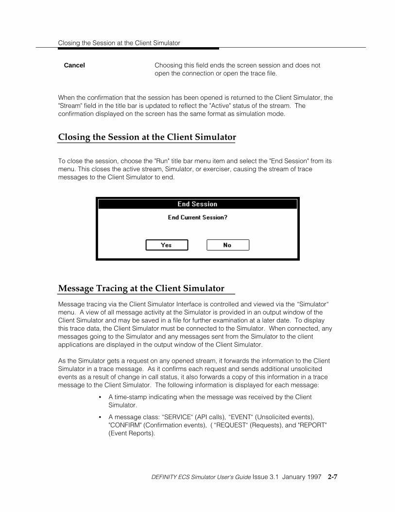
Closing the Session at the Client Simulator
To close the session, choose the "Run" title bar menu item and select the "End Session" from itsmenu. This closes the active stream, Simulator, or exerciser, causing the stream of tracemessages to the Client Simulator to end.
Message Tracing at the Client Simulator
Message tracing via the Client Simulator Interface is controlled and viewed via the “Simulator“menu. A view of all message activity at the Simulator is provided in an output window of theClient Simulator and may be saved in a file for further examination at a later date. To displaythis trace data, the Client Simulator must be connected to the Simulator. When connected, anymessages going to the Simulator and any messages sent from the Simulator to the clientapplications are displayed in the output window of the Client Simulator.
As the Simulator gets a request on any opened stream, it forwards the information to the ClientSimulator in a trace message. As it confirms each request and sends additional unsolicitedevents as a result of change in call status, it also forwards a copy of this information in a tracemessage to the Client Simulator. The following information is displayed for each message:
• A time-stamp indicating when the message was received by the ClientSimulator.
• A message class: “SERVICE“ (API calls), “EVENT“ (Unsolicited events),"CONFIRM" (Confirmation events), ( “REQUEST“ (Requests), and "REPORT"(Event Reports).

Using the Simulator
2-8 January 1997 Issue 3.1 DEFINITY ECS Simulator User‘s Guide
• A number identifying the sender of a request or receiver of a confirmationmessage (driverHandle). This field is zero for EVENT reports which are notreported on a per client basis. This field is always zero when running inexerciser mode because the only messages displayed are those sent/receivedby the Client Simulator.
• A message type indicating the type of request, confirmation or event.
• Detailed information that is specific to each message type.
Simulating Manual Operations
Applications can change the state of a device or call by sending CSTA requests and respondingto the resulting messages. In actual use, however, the devices and calls can be affected bymanual operations (for example, people picking up their handsets) or by CSTA requests placedby other applications. Any application that deals with telephony must be able to respond tosuch changes in call and station states.
There are two menus that handle the simulation of these two types of manual operations, the"PBX" menu and the "Functions" menu. The "PBX" menu on the Client Simulator lists messageswhich cannot be done via any CSTA or private G3 function. These manual operations are "GoOff-hook", "Go on-hook", "Call In-bound", "Finish Monitor", "End Route", "Enable Link", and"Disable Link". [These messages are not enabled when an exerciser stream is established sincean actual PBX is available to perform the manual operations.] In the sample screen that follows,we have Selected the “Off-hook“ operation:

Simulating Manual Operations
DEFINITY ECS Simulator User‘s Guide Issue 3.1 January 1997 2-9
Other manual operations, like dialing the phone to make a call, putting a phone call on hold byhitting the hold button, or requesting that a phone be forwarded by dialing the feature accesscode can be simulated using the CSTA and private G3 messages in the "Functions" menu:

Using the Simulator
2-10 January 1997 Issue 3.1 DEFINITY ECS Simulator User‘s Guide
These operations can all be simulated at any time during the simulation.
For example, to clear an established call and place all the phones back on-hook, any of thefollowing techniques could be used:
• The application under test could request a "clear connection" which wouldautomatically clear the connection and place the two parties on-hook.
• The Client Simulator could request the "on-hook" manual operation for one ofthe two devices using the "PBX/Go On-hook" message.
• The Client Simulator could request a "Functions/clear call" message.

Using the Simulator Console Interface
DEFINITY ECS Simulator User‘s Guide Issue 3.1 January 1997 2-11
Using the Simulator Console Interface
This section details the simulator console interface for Telephony Services Release 2 forWindows NT.
A Server Console application (simcons.exe) that runs on the NT server’s console screen issupplied with the Simulator. It provides an interface to the simulator that displays not only thestatic administration of the simulator, but also the dynamic state of the calls and devices andany other state at any given point in time. It allows you to view information more convenientlythan having to continuously query through the Client Simulator interface (clsim.exe).
The simcons.exe application will only run on the server where the Telephony Server andsimulator are loaded, and should only be started after the simulator has been loaded by theTelephony Server. It is not necessary to run the simcons.exe application for the simulator towork; however, it may prove to be an effective tool to understand the simulator and how yourapplication interacts with it. An icon is provided by the installer in the Telephony Services for theNT folder to run the simcons.exe application.
Two rules apply when using the console interface:
1. The Simulator DLL must already be loaded by the Tserver service.
2. Both the TServer and the simcons.exe application must load the DLL from thesame directory.
If either of these conditions is not met, the Simulator DLL cannot be started and the simulatorconsole interface will not run. The following dialog box will appear:

Using the Simulator
2-12 January 1997 Issue 3.1 DEFINITY ECS Simulator User‘s Guide
The Browse button on this dialog box allows the user to select a file to be loaded by thesimulator the next time the simulator is loaded by the Telephony Server. This field is kept in theregistry so the setting will remain until the next time the user selects the Browse button andchanges the file to something different.

Using the Simulator Console Interface
DEFINITY ECS Simulator User‘s Guide Issue 3.1 January 1997 2-13
Main Dialog Box
When the Simulator console interface is successfully loaded, the following dialog box appears:
This dialog box allows you to: 1) display information about active calls, devices, monitors, orsessions, 2) change some simulator settings, or 3) close the application. These activities aredetailed in the remainder of this chapter.

Using the Simulator
2-14 January 1997 Issue 3.1 DEFINITY ECS Simulator User‘s Guide
Active Calls Button
The Active Calls button, one of the four Display Information options, displays information aboutthe currently active calls in the simulator. When you select Active Calls, the Active CallInformation dialog box appears:
The five tabs across the top of the Active Call Information Dialog Box indicate the types ofinformation available. The Active Call IDs drop down combo box on the left appears on everytab and displays Call IDs of all calls that were active when the Active Calls button was selected.You may select a new call ID at any time.
When you select other tabs for a call, the information displayed for that call relates to the call atthe moment you selected the Call ID in the drop down combo box. Thus, the information may beout of date. See the information on the Invalid Call ID dialog box and the Refresh button thatfollows.

Using the Simulator Console Interface
DEFINITY ECS Simulator User‘s Guide Issue 3.1 January 1997 2-15
When the dialog box is first displayed, information for the Connections tab (this is the defaulttab) is displayed and the first call in the list is automatically selected. If there are no active calls,the drop down combo box is blank.
NOTE:
If the Active Call Ids combo box is out of date and you select a Call ID that is nolonger active, the following dialog box will appear and you can Refresh or Cancel.This applies to all tabs.
Connections Tab
The Connections tab dialog shown previously displays connection information abut a selectedcall. The connections tab fields are as follows:
Device Id and ConnectionState
Displays all connections currently on the call (at the time youselected the call ID). Displays both the device ID and thelocal connection state of that connection. Also displaysqueued and failed connections. If a call is waiting for a routeselect or collected digits, then there will be only oneconnection displayed in this box, the connection from whichthe call originated.

Using the Simulator
2-16 January 1997 Issue 3.1 DEFINITY ECS Simulator User‘s Guide
The five buttons that appear on Active Call Information dialog boxes are as follows:
Refresh Updates the list of active calls in the Active Calls Ids combobox. Blanks out all fields. (Select a new call ID to see currentinformation.)
OK Returns you to Main Dialog box
Cancel Returns you to Main Dialog Box
Apply Not used
Help Not used
If the Invalid Call ID combo box appears, refer back to the Active Calls Button section forinformation.

Using the Simulator Console Interface
DEFINITY ECS Simulator User‘s Guide Issue 3.1 January 1997 2-17
UUI Tab
The UUI (User to User Information) tab displays the current UUI associated with the call and anyConnection Cleared UUI. If no UUI is associated with the selected call, then no UUI isdisplayed.

Using the Simulator
2-18 January 1997 Issue 3.1 DEFINITY ECS Simulator User‘s Guide
The UUI tab fields are as follows:
Current User to User Information:
The fields in this section display the User to User Information (UUI) currently associated with theactive call. The UUI can be set via private data on various CSTA requests such as make calland consultation call.
Type Denotes the type of UUI that is present with the active call. Itcan be one of three values, UUI_NONE indicating that thereis no private data, UUI_IA5_ASCII indicating that it is anASCII string, and UUI_USER_SPECIFIC indicating that it is asequence of bytes.
Length Denotes the length of the UUI data. If there is UUI it will be apositive number up to 32 bytes. If the type is UUI_NONEthen this field will contain "na".
Data Displays the data. Currently this field will only accuratelydisplay UUI_IA5_ASCII data. If UUI_USER_SPECIFIC data isencountered with embedded nulls or no null terminator, thenunpredictable results will occur.
Connection Cleared User to User Information:
The fields in this section display the User to User Information (UUI) associated with any clearconnection requests or reconnect call requests on the call. This UUI has no connection to OCIUUI or Current UUI. This UUI is only passed back with the connection cleared events.
Type Denotes the type of UUI that is present with the active call. Itcan be one of three values, UUI_NONE indicating that thereis no private data, UUI_IA5_ASCII indicating that it is anASCII string, and UUI_USER_SPECIFIC indicating that it is asequence of bytes.
Length Denotes the length of the UUI data. If there is UUI it will be apositive number up to 32 bytes. If the type is UUI_NONEthen this field will contain "na".
Data Displays the data. Currently this field will only accuratelydisplay UUI_IA5_ASCII data. If UUI_USER_SPECIFIC data isencountered with embedded nulls or no null terminator, thenunpredictable results will occur.
If the Invalid Call ID combo box appears, refer back to the Active Calls Button section forinformation.

Using the Simulator Console Interface
DEFINITY ECS Simulator User‘s Guide Issue 3.1 January 1997 2-19
Routing Tab
The Routing Tab displays routing information pertinent to the selected call.
The Routing tab fields are as follows:
Routing Information:
The fields in this section relate to calls that are currently waiting for a route select to be returnedfrom a registered routing server application. In order for the call to be in a state where it iswaiting for a route select, the called device must be an ACD that was administered as a routingACD and that currently has a registered routing server.
Is simulator waiting fora Route Select?
This field can be either "YES" or "NO". If it is "NO", then thecall either was never routed or is no longer waiting to receivea route select from a routing server. The following threefields will be populated with "na" (not applicable) when thisfield is set to "NO".

Using the Simulator
2-20 January 1997 Issue 3.1 DEFINITY ECS Simulator User‘s Guide
Route Register RequestID
When the "Simulator is waiting for a Route Select" field is setto "YES", then this field will display the Route RegisterRequest ID that is used to identify the routing server’sregistration session. It is the same ID that was returned inthe confirmation event to the CSTARouteRegisterRequest.
Routing CrossReference ID
When the "Simulator is waiting for a Route Select" field is setto "YES", then this field will display the Routing Cross Ref IDthat uniquely identifies the specific routing dialog between theSimulator and the routing server.
Session ID When the "Simulator is waiting for a Route Select" field is setto "YES", then this field will display the session ID thatcorresponds to the open stream over which the route requesthas been sent to the routing server.
If the Invalid Call ID combo box appears, refer back to the Active Calls Button section forinformation.
UEC Tab
The UEC (User Entered Code) tab displays the UEC associated with the selected call and alsoindicates whether the selected call is currently waiting for collected digits.

Using the Simulator Console Interface
DEFINITY ECS Simulator User‘s Guide Issue 3.1 January 1997 2-21
The UEC tab fields are as follows:
Digit Collection Information :
This section contains only one field: "Is call waiting for Collected Digits?". This field will bepopulated with either "YES" or "NO". If it is displaying "YES", then the following conditions aretrue:
• The call was placed to an ACD that is administered to collect digits.• The ACD is being monitored by monitor calls via device.• There are currently client Simulator interfaces (CLSIM application) with streams open to this Simulator.
When the call is waiting for collected digits, it has sent a message to all of the Client SimulatorInterfaces that have streams open to it, and requests that one of them respond with digitsbefore a time-out period expires. As soon as one of the Client Simulator Interfaces respondswith digits or the time-out expires, then the call will no longer wait for collected digits and the "Iscall waiting for Collected Digits?" field will be set to "NO".

Using the Simulator
2-22 January 1997 Issue 3.1 DEFINITY ECS Simulator User‘s Guide
Current User Entered Code:
The fields in this section are as follows:
Type This field denotes the type of User Entered Code (UEC) thatis currently associated with the call. It can be one of anumber of types:
• UE_NONE indicating that there is NO UEC.
• UE_CALL_PROMPTER indicating that the data (digits) werecollected via the collect digits mechanism built into theSimulator.
• UE_DATA_BASE_PROVIDED indicating that the data wasprovided via the route select message. (The G3 PBX Driverhas more values for this field but they are not supported bythe G3 Simulator.)
Indicator This field denotes whether the digits were collected orentered. It can have one of two values:
• UE_COLLECTED - This value indicates that the digits werecollected via the digit collection mechanism in the Simulator(analogous to call prompter digits in the G3PD).
• UE_ENTERED -This value indicates that the digits wereuser-provided in a route select message.
Data This field contains the data (up to 24 characters) that wascollected or entered for this active call.
Collect VDN If the digits were collected via the digit collection mechanism,then this field will contain the device ID of the VDN thatcollected the digits. If the digits were entered via a routeselect message, then this field will be null.
If the Invalid Call ID combo box appears, refer back to the Active Calls Button section forinformation.
Using the Simulator Console Interface
DEFINITY ECS Simulator User‘s Guide Issue 3.1 January 1997 2-23
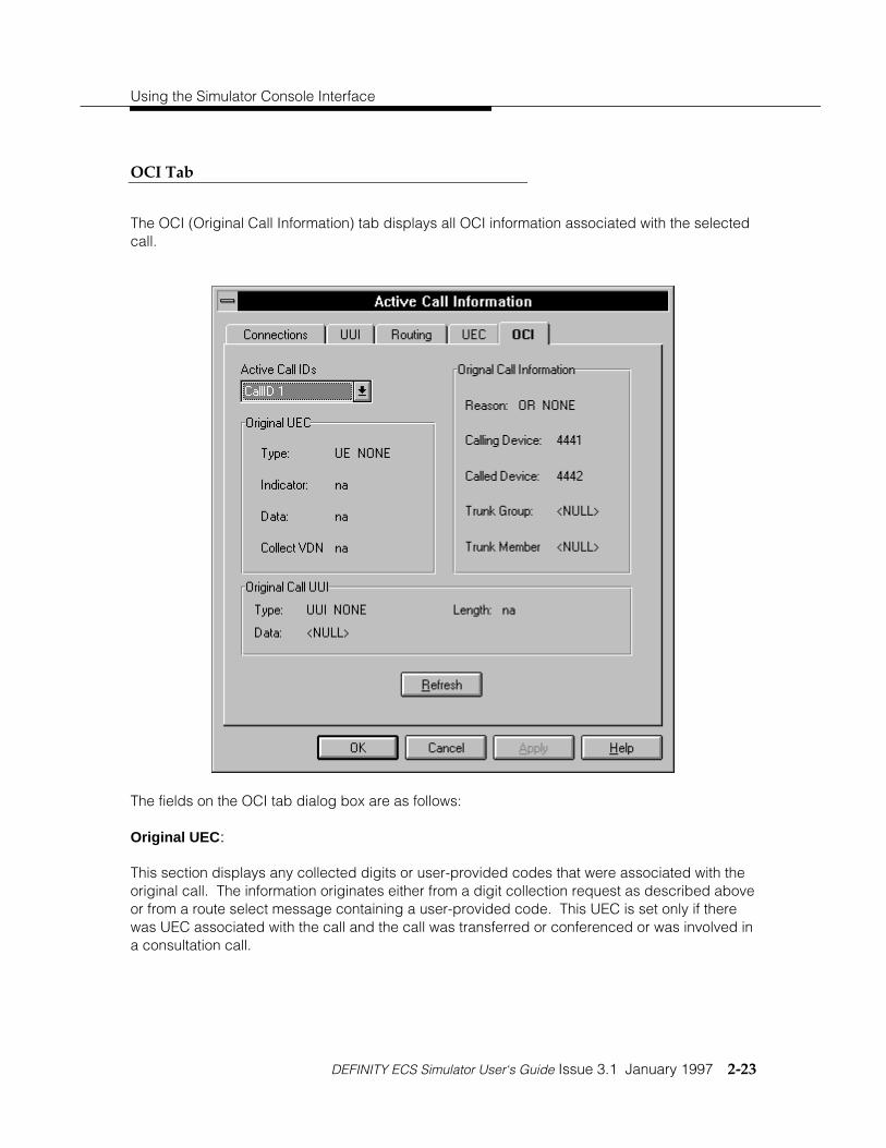
OCI Tab
The OCI (Original Call Information) tab displays all OCI information associated with the selectedcall.
The fields on the OCI tab dialog box are as follows:
Original UEC:
This section displays any collected digits or user-provided codes that were associated with theoriginal call. The information originates either from a digit collection request as described aboveor from a route select message containing a user-provided code. This UEC is set only if therewas UEC associated with the call and the call was transferred or conferenced or was involved ina consultation call.

Using the Simulator
2-24 January 1997 Issue 3.1 DEFINITY ECS Simulator User‘s Guide
Type This field denotes the type of User Entered Code (UEC) thatis currently associated with the call. It can be any of thefollowing:
• UE_NONE indicating that there is NO UEC.
• UE_CALL_PROMPTER indicating that the data (digits) werecollected via the collect digits mechanism built into theSimulator.
• UE_DATA_BASE_PROVIDED indicating that the data wasprovided via the route select message. (The G3 PBX Driverhas more values for this field but they are not supported bythe G3 Simulator.)
Indicator This field denotes whether the digits were collected orentered. It can have one of two values:
• UE_COLLECTED - This value indicates that the digits werecollected via the digit collection mechanism in the Simulator(analogous to call prompter digits in the G3PD).
• UE_ENTERED - This value indicates that the digits wereuser-provided in a route select message.
Data This field contains the data (up to 24 characters) that wascollected or entered for this active call.
Collect VDN If the digits were collected via the digit collection mechanism,then this field will contain the device ID of the VDN thatcollected the digits. If the digits were entered via a routeselect message, then this field will be null.
Original Call Information :
The fields in this section display information about the call when it was originally set up. The OCIhas meaning when a call has been transferred or conferenced, or was involved in a consultationcall.
Reason This field denotes the reason for the original call information.It can be any of the following: OR_TRANSFERRED,OR_CONFERENCED, OR_CONSULTATION, OR_NEW_CALL,or OR_NONE.

Using the Simulator Console Interface
DEFINITY ECS Simulator User‘s Guide Issue 3.1 January 1997 2-25
Calling Device Displays the original calling device on the call.
Called Device Displays the original called device on the call.
Trunk Group Displays the trunk group number from which the calloriginated (if applicable; otherwise, NULL is displayed).
Trunk Member This field is currently not in use and always displays NULL.
Original Call UUI :
The fields in this section display the User to User Information (UUI) associated with the originalcall. This UUI is set only if there was UUI associated with a call and the call was transferred orconferenced or was involved in a consultation call.
Type Denotes the type of UUI that is present with the active call. Itcan be one of three values, UUI_NONE indicating that thereis no private data, UUI_IA5_ASCII indicating that it is anASCII string, and UUI_USER_SPECIFIC indicating that it is asequence of bytes.
Length Denotes the length of the UUI data. If there is UUI it will be apositive number up to 32 bytes. If the type is UUI_NONEthen this field will contain "na".
Data Displays the data. Currently this field will only accuratelydisplay UUI_IA5_ASCII data. If UUI_USER_SPECIFIC data isencountered with embedded nulls or no null terminator, thenunpredictable results will occur.
If the Invalid Call ID combo box appears, refer back to the Active Calls Button section forinformation.
Devices Button
The Devices button on the Main Dialog Box allows you to display information about alladministered devices known by the simulator. The Administered Devices dialog box is asfollows:

Using the Simulator
2-26 January 1997 Issue 3.1 DEFINITY ECS Simulator User‘s Guide
The three radio buttons on the right indicate the types of information available for AdministeredDevices. When the dialog box is first displayed, List Administered Stations, the default, isselected, and information for all administered stations appears in the list box.
As you select different radio buttons, the list box updates with corresponding devices. To viewadditional information about specific devices, select the desired radio button and then select adevice in the list box by double clicking on it or highlighting it and then selecting MoreInformation.
List Administered Stations Radio Button:
The list box on the left displays a list of all administered stations. To view more detailedinformation about a selected station, select More Info. The Station <extension> InformationDialog Box that follows in the next section appears.
Station <extension> Information Dialog Box
If you select the List Administered Stations radio button, highlight a device for which you wantmore detailed information, and then select more Information, the Station <extension>Information dialog box appears.

Using the Simulator Console Interface
DEFINITY ECS Simulator User‘s Guide Issue 3.1 January 1997 2-27
The fields in the Station <extension> Information dialog box are as follows:
Station Features:
Coverage Administered Indicates via "YES" or "NO" whether the station has coverageadministered. If coverage is administered, then featuressuch as Do Not Disturb and Coverage on No Answer can beused.
Coverage Destination This field is only applicable if coverage is administered. If it isadministered, then a station extension denoting the coveringdevice will be displayed in this field.
Forwarding Indicates whether forwarding is "On", "Off", or "NotAdministered". If it is "On", then the Forwarding Destinationfield will contain the destination to which it is forwarded.
Forwarding Destination: If the Forwarding field indicates that forwarding is set "On",then this field will contain the destination to which the stationis forwarding.

Using the Simulator
2-28 January 1997 Issue 3.1 DEFINITY ECS Simulator User‘s Guide
Do Not Disturb Indicates if the Do Not Disturb feature is "On", "Off", or "NotAdministered." This feature can only be administered inconjunction with coverage.
Message WaitingIndicator
Indicates whether the station’s Message Waiting Indicatorlamp is "On", "Off," or if it does not have a Message WaitingIndicator.
Station Information:
Agent Station Indicates whether the selected station is an administeredagent in an ACD. If it is an agent station, then furtherinformation can be found out about the station via the "ListAdministered ACDs" option on the "Administered Devices"dialog box.
Speakerphone Indicates whether the station is administered with aspeakerphone. The existence of a speakerphone indicates tothe Simulator that it can automatically take the station off-hook when initiating a call or answering a call through theanswerCall feature. If no speakerphone is administered, thenthe user must manually go off-hook before initiating a makecall. This can be done through the Client Simulator Interface.
Auto Answer Indicates whether the station will automatically answer anincoming call into the station. For a station to beadministered as auto answer, it must also have aspeakerphone administered.
Switch Hook State Indicates the switch hook state of the station. Valid valuesare on-hook, idle, dialtone, or busy. Idle indicates the stationis off-hook but has no initiated call (that is, no dialtone).Dialtone indicates that the station is off-hook and hearsdialtone (that is, an initiated call). Busy indicates that thestation is off-hook and is on an active call.

Using the Simulator Console Interface
DEFINITY ECS Simulator User‘s Guide Issue 3.1 January 1997 2-29
Call Appearance States:
The five lines in this section indicate the status of a maximum of five call appearances that canbe administered for a station. If the call appearance is administered, it will display any activecall ID associated with the call appearance and its state. If the call appearance is notadministered, it will indicate it as such.
Call Control Parameters:
Alert Time The call control attribute that indicates how long to simulatethe alerting state of a call coming into this station. If it iszero, then the call will stay in the alerting state untilspecifically acted upon.
Connect Time The call control attribute that indicates how long to simulatethe connected state of a call coming into this station beforethe Simulator will drop the call. If it is zero, then the call willstay in the connected state until specifically acted upon.
Fail Time The call control attribute that indicates how long to simulate afailed connection to this station before dropping the call. If itis zero, then any call in the failed state associated with thisstation will stay in the failed state until terminated.

Using the Simulator
2-30 January 1997 Issue 3.1 DEFINITY ECS Simulator User‘s Guide
List Administered ACDs Radio Button:
When you select the List Administered ACDs radio button on the Administered Devices Box, thelist box on the left displays a list of all administered ACDs.
To view more detailed information about a selected device in the list box, press More Info. TheACD <extension> Information tab dialog box that follows in the next section appears.

Using the Simulator Console Interface
DEFINITY ECS Simulator User‘s Guide Issue 3.1 January 1997 2-31
ACD <extension> Information Dialog Box
This dialog box contains information about the ACD selected when the List Administered ACDsradio button is selected.
The ACD <extension> Information dialog box fields are as follows:
General Information
The fields in this section contain information about the agents and calls in the queue.
Using the Simulator
2-32 January 1997 Issue 3.1 DEFINITY ECS Simulator User‘s Guide
Total Agents Administered Shows the total number of agents that have beenadministered as part of this ACD. NOTE: This is differentfrom the DEFINITY PBX switch implementation that allowsagents to be logged into different ACDs (VDNs). TheSimulator associates an agent with a station extension andthat agent is administered into a maximum of one ACD. Theagent may only log into and out of the ACD in which he or sheis administered.
Number of agents logged in Shows the number of agents that are currently in a logged instate for this ACD. As a default, all agents administered in anACD will be logged in and in a ready state when the Simulatoris loaded by the Tserver. This number can never be greaterthan the total number of agents administered for the ACD. Ifno agents are logged in and a call comes into the ACD, oneof the following will occur: a) The call will still queue and willwait until an agent logs in and becomes ready, b) the call willtime out in the queue, or c) the call will be terminated.
Number of available agents Shows the number of agents that are currently in theAG_READY state with a talk state of TS_IDLE (see thePassageWay Telephony Services for Windows NT DEFINITYSystem Programmer’s Guide for more detailed information).This number can never be greater than the number of agentsthat are logged into the ACD.
Number of calls in queue Shows the number of calls that are currently queued at thisACD waiting for an available agent. The calls will remain inqueue until an agent becomes available, the call times out ofthe queue and is terminated, or the call is disconnected by aclear call or on-hook operation.
Routing Information:
This section displays information about whether this ACD is administered as a routing deviceand if there are any routing servers registered with this device.
Administered as a routingserver
Indicates whether this particular ACD is administered as arouting device. If it is administered as a routing device andthere is a registered routing server, either a specific one forthis device or a default routing server, then any calls cominginto this ACD will cause a route request to be sent to therouting server and the call will wait for the route select ortime-out and route to an agent in the group.

Using the Simulator Console Interface
DEFINITY ECS Simulator User‘s Guide Issue 3.1 January 1997 2-33
Route Request timeout(ms)
If this ACD is administered as a routing device, then this fieldindicates the amount of time that the device will wait (inmilliseconds) for a route select to be returned from therouting server. If the ACD is not a routing device, then thisfield will display "na".
Routing Server registerrequest ID
Displays the routing register request ID of a registeredrouting server if one has registered. If there is no registeredserver, then this field will display "None Registered". If theACD is not a routing device, then this field will display "na".
Routing Server TSDI handle Displays the handle of the open stream session over whichthe routing server has registered if one has registered andthis is an administered routing device. Otherwise, it willdisplay "na".
Digit Collection Information:
This section displays information about the mechanism that the Simulator uses for digitcollection (that is, call prompter digits).
Administered to collectdigits
Indicates whether this ACD has been administered to performdigit collection. NOTE: Before digit collection will beperformed on calls coming into this ACD, it must have amonitor call via device session opened to it. This is done tomimic the G3 PBX Driver behavior. If the events from thismonitoring session are not of interest, then they can befiltered out using the csta filtering mechanism.
Number of digits to collect If this ACD is administered to collect digits, then this fieldindicates the number of digits for which the Client SimulatorInterface will prompt. Otherwise, this field will display "na".
Digit collection timeout If this ACD is administered to collect digits, then this fieldindicates how long the Simulator will wait for a reply from anyClient Simulator Interface for the collected digits before timingout and continuing the call’s progress. Otherwise, this fieldwill display "na".

Using the Simulator
2-34 January 1997 Issue 3.1 DEFINITY ECS Simulator User‘s Guide
View Agents Dialog Box:
While the ACD <extension> Information dialog box is displayed, to see more detailedinformation about agents administered for a selected ACD, select View Agents. The followingdialog box appears:‘
This dialog box displays information about administered agents for an ACD displayed on thepreceding dialog box. The fields are as follows:
DeviceID Displays the extension number of the administered agent inthe ACD.
Agent State Displays the agents CSTA Agent State which can be any ofthe possible agent states except AG_WORK_READY which isnot supported by the G3 Simulator or G3 PBX Driver.
Work Mode Displays the agent′s G3 private Work Mode state which canbe any one of the four possible work modes.
Talk State Displays the agent′s G3 private Talk State, which can eitherbe TS_IDLE or TS_ON_CALL.

Using the Simulator Console Interface
DEFINITY ECS Simulator User‘s Guide Issue 3.1 January 1997 2-35
List Administered Trunk Groups Radio Button:
When you select Administered Trunk Groups radio button on the Administered Devices dialogbox, all administered trunk groups are displayed in the list box on the left.
To view more detailed information about a selected trunk, highlight it in the list box and pressMore Info. The dialog box that follows will appear.
The Trunk Member Information combo box lists the status (In Use or Idle) of each trunk groupmember.

Using the Simulator
2-36 January 1997 Issue 3.1 DEFINITY ECS Simulator User‘s Guide
Monitors Button
When you select the Monitors Button on the Main Dialog box, the dialog box that followsappears:
The active monitors are displayed in the list box on the left. To display the various types ofactive monitors/traces, select the corresponding radio button.

Using the Simulator Console Interface
DEFINITY ECS Simulator User‘s Guide Issue 3.1 January 1997 2-37
Sessions Button
When you select the Sessions Button on the Main Dialog box, the dialog box that followsappears:
The active Session Ids are displayed in the list box on the left. The first session is selected whenthe dialog first appears, and the information corresponding to that session is displayed on theright. If there are no active sessions, then no information is displayed in the fields.
The Session Information fields are as follows:
Login ID Denotes the login ID used by the application to open thestream to the advertised service.
Application Name This is the string that the application passed in theacsOpenStream call which identifies itself.
Server ID Denotes the advertised service name to which the applicationopened the stream.

Using the Simulator
2-38 January 1997 Issue 3.1 DEFINITY ECS Simulator User‘s Guide
Session ID Denotes the value passed back to the application to uniquelyidentify the session.
Stream Type Denotes the type of stream that is opened. It can either beST_CSTA indicating a CSTA stream or it can be ST_OAMindicating that it is a stream opened by the client Simulatorinterface.
API Version Denotes the version of the API requested by the application.
Library Version Denotes the version of the TSLIB library being used by theapplication.
Tserver Version Denotes the version of the Tserver being used.
Negotiated Private DataVersion
Denotes the version of private data negotiated by theapplication and the Simulator. If none was negotiated then"No Private Data" will be displayed here.
TSDI Handle Denotes the value given to the simulator to identify the TSDIinterface to communicate over.
Tracing CL_SIM? Denotes whether this application is a CLSIM application and ifit is tracing or not.

Using the Simulator Console Interface
DEFINITY ECS Simulator User‘s Guide Issue 3.1 January 1997 2-39
Settings Button
When you select the Settings button on the Main Dialog box, the following dialog box appears:
The options on this box allow you to change switch versions or the virtual link status. Select thedesired option and press OK, or press Cancel to leave the settings as is.
The radio buttons on the Settings dialog box are as follows:
Switch Version:
DEFINITY G3V3/DEFINITYG3V4
Identifies the message set supported and allows you tochange the DEFINITY switch version that the Simulatorsupports. It is recommended that any application developedwith the Simulator be thoroughly tested with the DEFINITYPBX.

Using the Simulator
2-40 January 1997 Issue 3.1 DEFINITY ECS Simulator User‘s Guide
Virtual Link Status:
Link Up/Link Down Allows you to enable or disable the G3 Simulator ’s virtual link,which would be analogous to taking down the ASAI link to theDEFINITY G3 PBX Driver. By doing so, you can see how anapplication reacts to the link going down. The link goingdown will cause:
1) all routing dialogs to be terminated with a route endmessage;
2) all routing registration sessions to be aborted with a routeregister abort message to the registered routing server;and
3) all monitoring sessions to be ended with a monitor endedevent, and all subsequent CSTA requests to be rejectedwith an appropriate error code.
The link can also be enabled/disabled from the ClientSimulator Interface.
Input File:
Currently loaded file This field displays the full path to the file that the simulatorused to load configuration information when it was loaded bythe Telephony Server. The information in this file will be useduntil the simulator is unloaded by the Telephony Server.
File to load at restart This field displays the full path to the file that the simulator willuse to load configuration information the next time it is loadedby the Telephony Server. This field will only be different fromthe Currently loaded file field if the user has previouslypressed the Browse button and selected a different input file.
Browse This button allows the user to select a file to be loaded by thesimulator the next time the simulator is loaded by theTelephony Server. This field is kept in the registry so thesetting will remain until the next time the user selects theBrowse button and changes the file to something different.

Using the Simulator Console Interface
DEFINITY ECS Simulator User‘s Guide Issue 3.1 January 1997 2-41
Close Button
Selecting the close button on the Main Dialog box exits you from the simulator console interface.
About SimCons Box
This box appears when you select About SimCons from the Main Dialog box. The icon on the leftis displayed at the bottom of the screen if you minimize the application.


DEFINITY ECS Simulator User‘s Guide Issue 3.1 January 1997 3-i
Chapter 3—Configuration Files
Introduction 3-1The File Menu 3-2The Admin Menu 3-3System Parameters 3-4Manual Digit Collection 3-5First Digit Table 3-6Stations 3-8Trunk Groups 3-16ACDs 3-19
Simulator Capacities 3-22Saving Configuration File(s) 3-23


Configuration Files
3
DEFINITY ECS Simulator User‘s Guide Issue 3.1 January 1997 3-1
Introduction
The Simulator is used to substitute for the PBX and all its stations and trunks. In order to workcorrectly, the Simulator must be made to look like the PBX. It must know about all the stations,trunks and ACDs, as well as the parameters specific to each, before it can know how to react toan application request. This PBX-like environment is created using the Client Simulator andsaved to a file which can then be read by the Simulator at startup time.
This chapter covers the steps necessary to create a configuration file to be used by theSimulator. Two items from the menu of the Client Simulator are used in creating and savingconfiguration data. The "file" menu option provides the file handling functionality to write data todisk or to read an existing file. The "Admin" menu option lists the general categories ofinformation required by each configuration file. These include:
• System Parameters
• First Digit Table
• Stations
• Trunk Groups
• ACDs
For information on loading the configuration in the Simulator, refer to Chapter 2.

Configuration Files
3-2 January 1997 Issue 3.1 DEFINITY ECS Simulator User‘s Guide
The File Menu
All the data entered to describe the configuration is saved in the memory of the Client Simulatorand written to a file when the user selects either the "Save" or "Save As" option in the "File" menu.This area of memory is initialized to zero on program invocation, but is not cleared again unlessthe "New" option on the "File" menu is selected. Thus, multiple configuration files can begenerated from the same set of input. After writing out the data the first time, the configurationcan be modified or added to and then written to a second file.
If an existing file is read using the "Open" option on the "File" menu, the data describing thesimulation is stored in this memory and can be modified and rewritten. While a file is opened,the name of the file is displayed in the title bar after the tag "Configuration: ". If no file has beenopened or the memory has been initialized by using the "New" option, the word "NEW" isdisplayed in the title bar.

The Admin Menu
DEFINITY ECS Simulator User‘s Guide Issue 3.1 January 1997 3-3
The Admin Menu
The "Admin" menu contains forms to administer all the devices that make up the PBXconfiguration. Users should be aware that these forms display data only for the Simulator. Thisinformation does not reflect any administered data on a PBX. In fact, this menu is disabledwhen an exerciser session has been established to prevent confusion between the two.
Choosing the "Admin" menu item generates the following display:
When this menu is selected after initializing memory with the "New" option, only the "SystemParameters" and "First Digit Table" are enabled. Data must be entered in the First Digit Tablebefore valid data can be entered in the "Station", "Trunk Groups" and "ACDs" forms. If anexisting file is read in, data in the first digit table of the file is examined and the appropriatefields enabled. For more details, refer to the "First Digit Table" section

Configuration Files
3-4 January 1997 Issue 3.1 DEFINITY ECS Simulator User‘s Guide
System Parameters
Parameters that affect Simulator operation globally are administered in the System Parametersform.
Coverage on No AnswerInterval
This field determines how long, in seconds, a call alerts at adestination device before the call goes to coverage, ifcoverage is administered for that station. See the section on"Alerting Time" in the station form section (Stations) thatfollows for details about interactions with that feature.
(Collect Digits RequestHandling) Manual Response
This field is the first choice under the Collect Digits RequestHandling. When you select this option, a dialog box isdisplayed when the Client Simulator receives a collect digitsrequest from the Simulator. (For more information, see the“Manual Collect Digits Dialog“ section that follows.)
(Collect Digits RequestHandling) AutomaticResponse
This field is the second choice under the Collect DigitsRequest Handling. When you select this option, the ClientSimulator automatically responds to the request for digitcollection by the Simulator without user input. The digitsgenerated are basically random.
(Collect Digits RequestHandling) Ignore Request
This field is the third choice under the Collect Digits RequestHandling. Selecting this option tells the application to ignoreall such requests for digits from the Simulator.
OK Choosing this field ends the screen session and saves thedata in memory.

The Admin Menu
DEFINITY ECS Simulator User‘s Guide Issue 3.1 January 1997 3-5
CANCEL Choosing this field ends the screen session and does notsave any data.
Manual Digit Collection
When you select the ÕManual ResponseÖ option under ÕCollect Digits Request HandlingÖ on theSystem Parameters form, the dialog box below is displayed when the Client Simulator receivesa collect digits request from the Simulator DLL. The Client Simulator will receive a collect digitsrequest when a call is made to an ACD that has Collect Digits administered and there is at leastone Monitor Calls Via Device session active for the ACD.
NOTE:The client Simulator must be running in Simulator mode and have tracingturned on to pop this dialog box.
Enter xx digits to becollected:
Enter 1-24 digits as was administered on the ACD Form. Thisfield will only appear if the "Collect Digits?" check box hasbeen Selected.
Number of Digits Entered This is a dynamic display showing the number of digits thatyou have entered thus far.
Digits Needed to be Entered This is a dynamic display showing the number of digits thatyou still must enter.
Ignore this AND futureCollect Digits Requests?
Check this box if you do not want to be prompted by theSimulator to supply the requested digits.

Configuration Files
3-6 January 1997 Issue 3.1 DEFINITY ECS Simulator User‘s Guide
OK Choosing this field ends the screen session and saves thedata in memory.
CANCEL Choosing this field ends the screen session and does notsave any data.
First Digit Table
When someone dials a number at a telephone on a PBX, the PBX that processes the numberneeds to know what type of number it is getting. For example, in many PBX installations, thenumber "9" is used to indicate that the user wants to get an outside trunk. When the PBXreceives a digit stream beginning with a "9", it knows that the number is to be treated as a trunk.Similarly, an on-PBX station whose DID number is 555-4213 can be accessed by other stationson the PBX by dialing "4213" because the PBX recognizes the "4" as an internal station type.Since these different types of devices are handled in very different ways by the PBX, it is muchmore efficient to classify them into types by their first digit.
The Simulator needs this type of information to streamline its own processing. It needs to knowwhat type of device is associated with each digit, "0" through "9". Once a device type has beenassigned to a digit, no other types of devices may use that first digit in their identifier. This isenforced by each form entry. For example, the station form checks that the first digit of theentered station extension maps to a station type in the first digit table. In fact, until at least onedigit is associated with a device group, the menu item for that device form is not enabled.
Choose First Digit Table to generate the following screen:

The Admin Menu
DEFINITY ECS Simulator User‘s Guide Issue 3.1 January 1997 3-7
First Digit This system generated field designates the first digit value.The range is from "0" to "9".
Type Data in this field determines whether the digits for this tableentry are associated with a trunk group access code ( tac),an extension, an acd or is not used (none). Valid values aretac, extension, acd and none. None is used to blank outthe previous selection.
Data in this field cannot be changed if there are any devicesadministered with this first digit. Use the "List" menu todetermine the devices with this first digit.
Number of Digits Data in this field defines the digit length of the tac, extensionor acd. Valid values are from 1 to 5 inclusive. A number isrequired if a device type has been entered for this digit. Ifthe device type is erased, this field is also cleared prior toaccepting the record.
Data in this field cannot be changed if there are any devicesadministered whose identifiers are this length. Use the "List"menu to determine the affected devices.
OK Choosing this field ends the screen session and saves thedata in memory.
CANCEL Choosing this field ends the screen session and does notsave any data.

Configuration Files
3-8 January 1997 Issue 3.1 DEFINITY ECS Simulator User‘s Guide
Stations
Selecting Stations will display a list of the currently administered stations. From this form, youmay create a new station record by pressing Create, or you may edit, duplicate, or delete anexisting entry by selecting that entry and pressing Edit, Duplicate, or Delete, respectively.

The Admin Menu
DEFINITY ECS Simulator User‘s Guide Issue 3.1 January 1997 3-9
Choosing either to create or edit an entry will cause the Station Form to appear:
The Station Form is used to add, change or delete stations in the station list. The key to thestation record is the extension. If the create option was used, all fields will appear blank and anew extension must be chosen. However, if the edit option was chosen, then the currentlyadministered values will appear. By entering a new station extension in the Station Extensionfield, if the entered extension is already in the list of extensions, the data for that record isdisplayed. If there is no record, the user may add the record by filling in the appropriateinformation. Once the data are correct, the changes/additions can be saved by pressing OK.Station records may be removed from the station list by entering the station extension, verifyingthat is indeed the station to be removed, and pressing Delete.
Pressing Duplicate permits the rapid addition of stations. When duplicating, one station recordacts as the "master" record and a copy is made whenever Duplicate is pressed. In duplicatingthe station, the Client Simulator automatically generates a new station extension by adding "1" tothe extension of the master record (or the last duplicated station). If adding "1" causes theextension to become illegal, for example, "499" becomes "500" and the first digit, "5", is not astation type, the Client Simulator looks for another first digit associated with stations. If none isfound, a message, "NO AVAILABLE EXTENSIONS - MODIFY FIRST DIGIT TABLE", is displayed.If more stations are needed, another first digit must be assigned to a station group.

Configuration Files
3-10 January 1997 Issue 3.1 DEFINITY ECS Simulator User‘s Guide
A station may not be deleted:
• if the station is a member of an ACD. If the station must be deleted, it must first bedeleted from the ACD. To find out which ACD the station is in, use the "list/ACDs" menuoption to display all ACDs and their member stations.
• if the station is the covering station for anot her station. The message "STATION ISREFERENCED BY ANOTHER STATION" is displayed if this error occurs. Use the"list/station" command to determine which stations are covered by this station.
• if another station is forwarded to this station. The message "STATION IS REFERENCEDBY ANOTHER STATION" is displayed if this error occurs. Use the "list/station" commandto determine which stations are forwarded to this station.
The Simulator replicates the call appearance functionality of the DEFINITY PBX. Regardless ofthe number of call appearances administered on a station, one call appearance is reserved sothat the user can always initiate a call. [This is necessary if users are to use the conference ortransfer features. Both of these features require that an active call be put on hold and a secondcall initiated.] If all call appearances but one are in use, the DEFINITY PBX does not deliver anincoming call to that station; the remaining call appearance is reserved for an outgoing call.Thus, if a station is administered with only one call appearance, it cannot receive incoming calls.To prevent this situation, the Simulator automatically administers two buttons as callappearances.
The fields on the Station Form are as follows:
Station Extension: This field designates the station extension. When a completeextension has been entered, the first digit of the extension ischecked against the first digit table to make sure the devicetype is "extension" and the length matches the number ofdigits in the extension. If the extension is correct, the ClientSimulator looks for a match in the station list. If a match isfound, the data for that extension is displayed.
Station Name: This field can be populated with an alphanumeric value thatwill then be associated with the specific station. The nameprovided in this field will be displayed on the list station formand will also be provided in future query functions.
Coverage Enabled? Coverage is a feature that causes an incoming call to bediverted to another station if the original station does notanswer in a preset amount of time. [The time interval for theSimulator is set on a system wide basis using the "SystemParameters" menu item.] If this field is not enabled,incoming calls alert until the station answers or the callerhangs up. Incoming calls can also be diverted if "Do NotDisturb" is administered and activated.

The Admin Menu
DEFINITY ECS Simulator User‘s Guide Issue 3.1 January 1997 3-11
Covering Extension: If the previous field has been chosen, this field must bepopulated with the covering extension. The entered station isvalidated against the list of stations. If it is not found, theerror "EXTENSION NOT VALID" is displayed.
Forwarding Enabled? Call forwarding is a feature that, when activated, immediatelydiverts incoming calls to the forwarding extension. If this fieldon the form is marked as enabled and no forwardingextension is provided, the feature is administered, but notactivated. It can be activated during the simulation run usingthe CSTASetForwarding message. If an extension isadministered, the feature is assumed to be activated.
Forwarding Extension: If the previous field is enabled, a forwarding extension maybe provided. If no extension is provided, forwarding isadministered but not activated. If an extension is provided,forwarding is administered and activated. The enteredstation is validated against the list of stations. If it is notfound, the error "EXTENSION NOT VALID" is displayed.
Speakerphone Available? Check this field if the station is to have a speakerphone. Aspeaker phone allows the Simulator to automatically take astation off-hook when initiating or answering a call. This isidentical to the switch functionality. If a station is notadministered with a speakerphone, the station must be in anoff-hook state before it can originate a call. This can be doneusing the "Send Message/Go Off-hook" option(Simulatormode) or manually going off-hook at the PBX(exercisermode). A station without a speakerphone cannotautomatically answer incoming calls.
Msg Waiting Indicator? Check this field if there is a message waiting indicator on thestation. If checked, the Simulator turns it on at the beginningof a simulation. The state can be modified by sending a"Send Message/Set Feature/Message Waiting Indicator"message.
Auto Answer? Choose this field to indicate that the station is auto answer.(This is typical of headset operation.) The significance ofAutoAnswer on a station is that it causes the Simulator toautomatically establish any call that is delivered to the stationas long as there is a speakerphone administered. A stationadministered with auto answer and a speakerphoneautomatically answers all incoming calls. If no speakerphoneis administered, the Simulator leaves the call in the alertingstate.

Configuration Files
3-12 January 1997 Issue 3.1 DEFINITY ECS Simulator User‘s Guide
Buttons 1 and 2: Feature telephones reserve one call appearance for outgoingcalls so that features like conference and transfer, whichrequire a second call appearance to make a call, cancomplete. If a station is administered with only one callappearance, it could not receive any incoming calls. For thisreason, buttons 1 and 2 are designated as call appearancesby the Client Simulator.
Buttons 3 to 5 Buttons 3 to 5 can be defined as call-app, send-calls ornone. The dropdown list box displays the valid choices forthis field. Each call appearance button represents the abilityto connect to another party.
Creating a "send all calls" (SAC) button allows the Do NotDisturb feature to be administered and activated. The stationmust have coverage enabled in order to administer the"send-all-calls" button. When the "send-all-calls" (or DND) isactivated, incoming calls are immediately diverted to thecovering extension.
Alerting Time: "Alerting time" is a Simulator-specific parameter that allows itto simulate call control. On an actual PBX this would equateto the time it takes for the station user to pick up the handset.The role of this field depends on several other features: thecoverage on no answer interval, call coverage for this stationand auto answer and speakerphone administration.
If the "alerting time" is "0", the station remains in an alertingstate until one of the following occurs: the coverage on noanswer time interval elapses (if the station has coverage), thecall is answered (CSTAAnswerCall() ) or the station is forcedoff-hook (Go Off-hook). A CSTAClearConnection/Call couldbe used to tear down the call.
If the station has coverage and the alerting time is non-zerobut less than the coverage on no answer interval, anincoming call is answered after an "alert time" interval haselapsed.
If the station has coverage and the alerting time is greaterthan the coverage on no answer interval, an incoming call isdiverted to the covering station after the "coverage on noanswer" interval has elapsed.

The Admin Menu
DEFINITY ECS Simulator User‘s Guide Issue 3.1 January 1997 3-13
Connected Time Connected time is a Simulator-specific parameter that allowsit to simulate call control. On an actual PBX this wouldequate to the time from when the user answers to the timewhen they hang up.
If the "connected time" is zero, the call, once established,remains in the established state until the connection isexplicitly dropped, e.g. by use of the CSTAClearConnection(),CSTAClearCall() or "Send Message/Go Onhook" (Simulatormode only).
If the "connected time" is greater than zero, the stationremains in the connected state for the designated amount oftime and then is automatically dropped from the call.
Connected time applies only to calls that have beenestablished by the call control simulation. If a call moves tothe established state as a result of a CSTAAnswer() requestor a Go-Off-hook message, the call stays established untilanother explicit request.

Configuration Files
3-14 January 1997 Issue 3.1 DEFINITY ECS Simulator User‘s Guide
Failed Time: When a call cannot be completed at a station, the stationgives some audible feedback as to why the call failed (e.g.,busy, reorder) and continues to give this feedback until theoriginator hangs up. This field provides the capability ofdropping a failed call automatically after a "failed time"interval instead of requiring a message explicitly dropping theconnection.
If the "failed time" is a positive number, the Simulator leavesthe connection in the failed state for that number of secondsand then drops the connection. If the "failed time" is "0", theconnection remains in the failed state.
NOTE:If a failed connection is dropped because of anelapsed Failed Time interval or CSTAClearCall/Connection, the Simulator leaves the deviceoff-hook, giving dialtone. A Service Initiated Eventis sent to any monitoring clients and the connectionis in the initiated state.
NOTE:Normally, the Failed Time used is the valueadministered for the called device. If, however, afailed event is received because of an invalidcalled destination, the Failed Time administered forthe calling device is used.
OK Choosing this field ends the screen session and saves thedata in the station list.
CANCEL Choosing this field ends the screen session and does notsave any data.
DUPLICATE Pressing Duplicate indicates that the information in thecurrent station record is to be duplicated in a second stationrecord. If the current record has not been saved, it is writtento the station list, a new station extension is generated andthe data displayed on the form. The user can make changesin this new record and duplicate it again. It is important tonote that the duplicated record with the new extension is notsaved in the station list until you press OK or Duplicate. IfCancel is pressed, the record is not saved. Only 50 stationrecords may be created in any one simulation file. If thisnumber is exceeded, the message "NO ROOM TO ADDSTATIONS" is displayed.

The Admin Menu
DEFINITY ECS Simulator User‘s Guide Issue 3.1 January 1997 3-15
DELETE This field removes a station record from the station list.Validations described above are made before the station maybe removed.

Configuration Files
3-16 January 1997 Issue 3.1 DEFINITY ECS Simulator User‘s Guide
Trunk Groups
A trunk group is a set of trunks which connect a PBX to the outside world. All members of thetrunk group are associated with the same Trunk Access Code or TAC. If a user wants to call anoutside number, he or she must dial the TAC of the trunk group to be used and then the actualnumber. This very basic functionality is simulated by the Simulator which uses the TAC in thedevice ID to pick the trunk group. It then picks one member of that group for the outgoing call.Subsequent changes to the connection states depend on the variables described below.
From the initial screen, choose the Admin title bar item and from its menu the "Trunk Groups"item. The following screen, which displays the currently administered trunk groups and theirassociated parameters, will appear:
From this screen, you may either choose an existing trunk group and select Edit to change theparameters of a trunk group or you may choose Create and enter a new trunk group andparameters. Selecting either of these options will cause the system to display the followingTrunk Group Form which you can populate or modify.
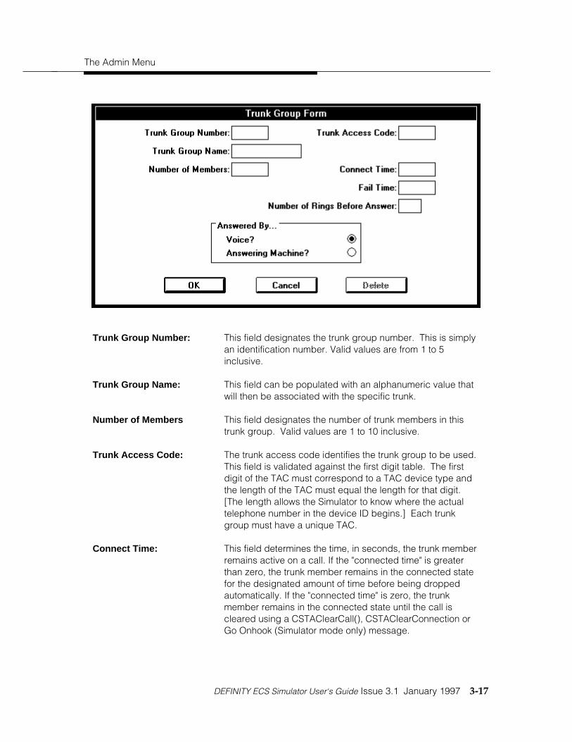
The Admin Menu
DEFINITY ECS Simulator User‘s Guide Issue 3.1 January 1997 3-17
Trunk Group Number: This field designates the trunk group number. This is simplyan identification number. Valid values are from 1 to 5inclusive.
Trunk Group Name: This field can be populated with an alphanumeric value thatwill then be associated with the specific trunk.
Number of Members This field designates the number of trunk members in thistrunk group. Valid values are 1 to 10 inclusive.
Trunk Access Code: The trunk access code identifies the trunk group to be used.This field is validated against the first digit table. The firstdigit of the TAC must correspond to a TAC device type andthe length of the TAC must equal the length for that digit.[The length allows the Simulator to know where the actualtelephone number in the device ID begins.] Each trunkgroup must have a unique TAC.
Connect Time: This field determines the time, in seconds, the trunk memberremains active on a call. If the "connected time" is greaterthan zero, the trunk member remains in the connected statefor the designated amount of time before being droppedautomatically. If the "connected time" is zero, the trunkmember remains in the connected state until the call iscleared using a CSTAClearCall(), CSTAClearConnection orGo Onhook (Simulator mode only) message.

Configuration Files
3-18 January 1997 Issue 3.1 DEFINITY ECS Simulator User‘s Guide
Fail Time: This field determines the time, in seconds, the trunk memberremains in the failed state before the connection is dropped.
NOTE:Normally the failed time used is the oneadministered for the called device. If, however,a call fails because the TAC is invalid, thecalling device remains in the failed state for aperiod of time corresponding to the failed timefor the originating device.
Number of Rings BeforeAnswer:
This field is used in conjunction with the make predictive callfeature. This field indicates how many times the call will ringbefore the Simulator "answers" the call. This means that theSimulator classifies the call as established at the off-PBXnumber. By classifying the call as established, this indicatesto the Simulator that the make predictive call can continuewith the call and try to establish the call at the originatingdevice. The value in this field is only used for the makepredictive call feature. This field defaults to 5 so that makepredictive calls that use the default of 10 maximum rings willbe classified as answered.
Answered By: This field is used in conjunction with the make predictive callfeature. This field indicates whether the off-PBX device isanswered by an answering machine or by a human. Thisallows the Simulator to simulate the Answering MachineDetection feature of the make predictive call. This field ismeaningless to any feature other than make predictive call.
OK Choosing this field ends the screen session and saves thedata in the trunk list.
CANCEL Choosing this field ends the screen session and does notsave any data.
DELETE This field removes the record from the trunk list in memory.

The Admin Menu
DEFINITY ECS Simulator User‘s Guide Issue 3.1 January 1997 3-19
ACDs
In the Simulator, an ACD is similar in functionality to, but more simplified than, a VDN in theDEFINITY PBX. It acts as a split extension for ACD agents for incoming calls. It also functionsas a routing device and as a mechanism for digit collection.
NOTE:The algorithm used to determine agent availability is greatly simplified from thatused by the PBX.
To create new ACDs or modify existing ones, Select the ACDs option under the Admin menu.By doing so, the following screen listing the currently administered ACDs will be displayed.
From this screen, you may either select an existing ACD and choose Edit to change theparameters of an ACD or you may choose Create and enter a new ACD and its associatedparameters. By selecting either of these options, the following ACD Form will appear for you topopulate or modify.

Configuration Files
3-20 January 1997 Issue 3.1 DEFINITY ECS Simulator User‘s Guide
ACD Extension: This field designates the extension of the ACD, commonlyreferred to as the "split extension". The first digit and numberof digits are checked against the first digit table to make surethe device type is "acd".
ACD Name This field can be populated with an alphanumeric value thatwill then be associated with the specific ACD.
Queuing Time An incoming call queues at the ACD if there is no availableagent. The queuing time simulates how long the caller waitsin the queue before giving up. If an agent becomes availablebefore this time expires, the queued call is routed to theagent. If the queuing time is "0", the call remains in thequeue until an agent becomes available or some messagefrom the application or Client Simulator acts on theconnection.

The Admin Menu
DEFINITY ECS Simulator User‘s Guide Issue 3.1 January 1997 3-21
Use Route Server? Selecting this check box will indicate that this ACD will allowan application to register with it as a routing server. The ACDwill then send a route request to the application when callscome into the ACD indicating that it needs a route selection.After the routing server application sends back a route selectto the Simulator, then the ACD will route the call to thedestination selected by the routing server.
Route Time-out: This item specifies the time (in seconds) that the ACD will waitfor a route select from a registered routing server. If thetime-out expires, then the ACD will route to the first availableagent in that ACD. This field will only appear if the "UseRoute Server?" check box has been selected.
NOTE:If you enter 0, time-out will be instantaneous.Since replying to the request may involve amanual step, you might want to leaveenough time to act on the request beforetime-out occurs.
Collect Digits? Selecting this check box will indicate that this ACD shouldprompt the user for digits whenever a call comes into theACD. All Client Simulators that have an open stream to thisSimulator will be prompted. The first one to respond will beused.
Number of Digits toCollect:
A number from 1-24 should be entered which indicates thenumber of digits that should be collected from the user. Thisfield will only appear if the "Collect Digits?" check box hasbeen selected.
Digit Collection Time-out: This item specifies the time (in seconds) that the Simulatorwill wait for the user to enter digits from the Client Simulatorinterface. If the Simulator has not received the digits afterthe time-out period, it will continue processing the call withoutpassing digits in the private data area.
NOTE:If you enter 0, time-out will be instantaneous.Since replying to the request may involve amanual step, you might want to leaveenough time to act on the request beforetime-out occurs.

Configuration Files
3-22 January 1997 Issue 3.1 DEFINITY ECS Simulator User‘s Guide
Ext 1 through 30 This field lists the extensions of the agents associated withthis ACD extension. Each entered station must be a validstation in the station list. A station may belong to only oneACD and may appear only once in that ACD.
OK Choosing this field ends the screen session and saves thedata in the ACD list.
CANCEL Choosing this field ends the screen session and does notenter any data.
DELETE This field removes the record from the ACD list.

Simulator Capacities
DEFINITY ECS Simulator User‘s Guide Issue 3.1 January 1997 3-23
Simulator Capacities
The following table is a capacity list for the Simulator. These numbers represent the maximumnumber of each type of device that may be administered in each configuration file. These limitsare enforced by the Client Simulator.
Maximum number of administrable stations: 50
Maximum number of call appearances per station: 5
Maximum number of trunk groups: 5
Maximum number of trunk group members: 10
Maximum number of ACDs: 10
Maximum number of monitoring sessions: 50
Saving Configuration File(s)
After entering the desired information, the file should be saved using the "Save" or "Save As"submenu items under the “File“ title bar menu item. This file should be saved on the server filesystem where the Simulator can locate it when loading, and must have a filename format of<filename>.sim.


DEFINITY ECS Simulator User‘s Guide Issue 3.1 January 1997 4-i
Chapter 4—Sending Messages to the Simulator DLL
Introduction 4-1Functions - Call Control Services 4-2Alternate Call 4-3Answer Call 4-5Call Completion 4-6Clear Call 4-7Clear Connection 4-8Conference Call 4-11Consultation Call 4-13Deflect Call 4-16Group Pickup Call 4-17Hold Call 4-18Make Call 4-19Make Predictive Call 4-22Pickup Call 4-25Reconnect Call 4-26Retrieve Call 4-29Transfer Call 4-30Send DTMF Tone 4-32
Functions - Escape Services 4-34Escape Service 4-35Escape Service Confirmation 4-37Send Private Event 4-38
Functions - Maintenance Services 4-39Change System Status Filter 4-40System Status Request 4-41System Status Start 4-42System Status Stop 4-44System Status Event Send 4-45System Status Request Confirmation 4-46System Status Filtering 4-47
Functions - Query Services 4-48Get API Capabilities 4-49Get Device List 4-50Query Call Monitor 4-52Query Agent State 4-53Query Device Information 4-55Query Do Not Disturb 4-56Query Forwarding 4-57

4-ii January 1997 Issue 3.1 DEFINITY ECS Simulator User‘s Guide
Query Last Number 4-58Query Message Waiting Indicator 4-59Query ACD Split 4-60Query Agent Login 4-61Query Call Classifier 4-62Query Device Name 4-63Query Station Status 4-64Query Time of Day 4-65Query Trunk Group 4-66
Functions - Routing Services 4-67Route System Parameters 4-68Route Tables (Automatic Routing Feature) 4-69Manual Routing Dialog 4-74Route End 4-76Route Register Cancel 4-77Route Register 4-78Route Select 4-79
Functions - Set Feature Services 4-83Set Agent State 4-84Set Do Not Disturb 4-86Set Forwarding 4-87Set Message Waiting Indicator 4-89
Functions - Snapshot Services 4-90Snapshot Call 4-91Snapshot Device 4-92
Functions - Status Reporting Services 4-93Change Monitor Filter 4-94Monitor Call 4-95Monitor Calls Via Device 4-96Monitor Device 4-97Monitor Stop 4-98Monitor Stop on Call 4-99Filter Selection 4-100
PBX Menu 4-102Off-hook 4-103On-hook 4-104In-bound Calls 4-105Finish Monitor 4-106Route End 4-107Disable Link 4-108

DEFINITY ECS Simulator User‘s Guide Issue 3.1 January 1997 4-iii
Enable Link 4-109
Simulator Menu 4-110Change Device Parameters 4-111Query Device 4-112Query Call 4-113Query All Active Calls 4-114Query All Stations 4-115Query All Trunk Groups 4-116Query All ACD Groups 4-117Query All Monitors 4-118Enable/Disable Tracing 4-119
Help Menu 4-120


Sending Messages to theSimulator 4
DEFINITY ECS Simulator User‘s Guide Issue 3.1 January 1997 4-1
Introduction
This chapter covers messages that can be sent over a CSTA stream to either a Simulator or aPBX Driver. All message types are listed under the three menus: ÕFunctionsÖ, ÕPBXÖ, andÕSimulatorÖ. To communicate with a Simulator, either a Simulator Session or an Exerciser sessionmust be initiated from the ÕRunÖ menu. To communicate with a PBX Driver, an Exerciser sessionmust be initiated from the ÕRunÖ menu.

Sending Messages to the Simulator
4-2 January 1997 Issue 3.1 DEFINITY ECS Simulator User‘s Guide
Functions - Call Control Services
Via the dialog boxes available from the “Functions/Call Control Services“ menu items, you canopt to generate CSTA messages to either the Simulator or PBX driver (exerciser mode). Thesedialog boxes provide the screens and field information for CSTA and G3 specific requests thatcan be made from the client Simulator and then sent to the Simulator on demand.
There is no validation performed on any data entered in any of these dialog boxes.

Functions - Call Control Services
DEFINITY ECS Simulator User‘s Guide Issue 3.1 January 1997 4-3
Alternate Call
TSAPI Function Name Escape Service Private Data G3PD Support Sim Support
cstaAlternateCall() (not applicable) No Yes Yes
This message provides a compound action of the Hold Call feature, followed by the Retrieve Callfeature. It causes an existing active call to move to the held state and then retrieves apreviously held call or connects an alerting call at the same device. If the held call can not beretrieved the call that was just put on hold will be retrieved and left in the active state.
Active Call ID: Enter the call ID that is provided in either the makecallconfirmation or the delivered event for the ACTIVE call on thedevice.
Active Device ID: Enter the device ID that is provided in either the makecallconfirmation or the delivered event for the ACTIVE call. Forthe Simulator and G3PD this should be the static stationextension for the device.

Sending Messages to the Simulator
4-4 January 1997 Issue 3.1 DEFINITY ECS Simulator User‘s Guide
Active Device Type: Select the device type for the active connection. For theSimulator and G3PD the only valid device type for aconnection ID for an Alternate Call request is Static.
Other Call ID: Enter the call ID that is provided by the Simulator for the heldor alerting call that will be used in the Alternate call action.
Other Device ID: Enter the device ID for the other call. The device ID shouldmatch that of the active device ID. For the Simulator andG3PD this should be the static station extension for thedevice.
Other Device Type: Select the device type for the other connection. For theSimulator and G3PD the only valid device type for aconnection ID for an Alternate Call request is Static.
Send Message Choosing this field sends the message.
Cancel Choosing this field voids the operation.

Functions - Call Control Services
DEFINITY ECS Simulator User‘s Guide Issue 3.1 January 1997 4-5
Answer Call
TSAPI Function Name Escape Service Private Data G3PD Support Sim Support
cstaAnswerCall() (not applicable) No Yes Yes
This message causes a device that is alerting to move to the established state; that is, toanswer the call. Answer cannot succeed unless the station is administered with a speakerphoneor the station is already off-hook and is idle or listening to dialtone.
Call ID: Enter the call ID that is provided in either the makecallconfirmation or the delivered event.
Device ID: Enter the device ID (station extension for Simulator andG3PD) of the device that is to answer the call.
Device Type: Select the device type for the connection. For the Simulatorand G3PD the only valid device type for a connection ID foran Answer Call request is Static.
Send Message Choosing this field sends the message.
Cancel Choosing this field voids the operation.

Sending Messages to the Simulator
4-6 January 1997 Issue 3.1 DEFINITY ECS Simulator User‘s Guide
Call Completion
TSAPI Function Name Escape Service Private Data G3PD Support Sim Support
cstaCallCompletion() (not applicable) No No No
This service invokes specific switch features that may complete a call that would otherwise fail.The feature to be activated is passed as a parameter to the function.
Feature: Select the feature for the Call Completion.
Call ID: Enter the call ID of the call that is to be completed via the CallCompletion feature.
Device ID: Enter the device ID from the connection ID for which the callcompletion is being activated.
Device Type: Enter the device type that is provided in the connection ID.
Send Message Choosing this field sends the message.
Cancel Choosing this field voids the operation.

Functions - Call Control Services
DEFINITY ECS Simulator User‘s Guide Issue 3.1 January 1997 4-7
Clear Call
TSAPI Function Name Escape Service Private Data G3PD Support Sim Support
cstaClearCall() (not applicable) No Yes Yes
This message disconnects all parties on an active call. In the Simulator, clearing a call that is inthe service initiated state will clear that call and cause a new call to be initiated. To not initiate anew call, put the station on-hook. Clearing a call of two or more parties on the Simulator willleave all parties in the on-hook state.
Call ID: Enter the call ID of the call that is to be torn down. This isprovided in the makecall confirmation or delivered orestablished events when the call is created.
Device ID: Enter the device ID from the connection ID that is being usedto identify the call. This is an optional field for the Simulatorand G3PD and will be ignored.
Device Type: Enter the device type of the device ID in the connection ID.This is an optional field for the Simulator and G3PD and willbe ignored.
Send Message Choosing this field sends the message.
Cancel Choosing this field voids the operation.

Sending Messages to the Simulator
4-8 January 1997 Issue 3.1 DEFINITY ECS Simulator User‘s Guide
Clear Connection
TSAPI Function Name Escape Service Private Data G3PD Support Sim Support
cstaClearConnection() (not applicable) Yes Yes Yes
This menu item enables the user to clear a specific connection on a call. For example, oneparty could be disconnected from an active call with three parties using clear connection. Thetwo remaining parties would remain on the call. Note, if the call had only two parties, the clearconnection would disconnect one and the remaining party would be disconnected since thereare no other parties on the call. An alerting connection cannot be cleared by the ClearConnection request. Also, in the Simulator, clearing a connection of just one party in the serviceinitiated state will cause the call to be cleared and a new call will be initiated. To not initiate anew call put the station on-hook.
The Clear Connection request also has the ability to add or to replace existing ConnectionCleared User to User Information on a call. By specifying up to 32 bytes of data in the UUI field,the Clear Connection request will add the Connection Cleared UUI to the call, replacing anyexisting Connection Cleared UUI associated with the call. Subsequent clear connection eventswill contain the updated UUI.
The first dialog box appears upon selecting the cstaClearConnection item under the“Functions/Call Control Services“ menu.

Functions - Call Control Services
DEFINITY ECS Simulator User‘s Guide Issue 3.1 January 1997 4-9
Call ID: Enter the call ID of the affected call.
Device ID: Enter the extension of the device that is to be dropped. Thisdevice must be a party on the call indicated by the call ID.
Device ID Type Choose the device ID Type that corresponds to theconnection ID that is being cleared. For the Simulator andG3PD this field should be specified as static for stations andACD groups. It is dynamic for trunk members. The callID/device ID connection should be what is provided in adelivered or an established event.
G3PD Private Data Selecting this button to open up a dialog box that allows forentering G3PD Private Data. All fields in the G3PD dialog boxare supported by the G3PD, but in some instances they arenot supported by the Simulator. See specific definitions offields for clarification.
Send Message Choosing this field sends the message.
Cancel Choosing this field voids the operation.
Close Choosing this button closes the dialog box and returns theuser to the previous dialog box. Any information entered inthe private data fields will be sent with the message if theSend Message button is selected.
The second dialog box appears when the G3PD Private Data button is selected.

Sending Messages to the Simulator
4-10 January 1997 Issue 3.1 DEFINITY ECS Simulator User‘s Guide
Drop Resource Specifies the resource to be dropped from the call. Theavailable resources are Call Classifier and Tone Generator.The tone generator is any G3 PBX applied denial tone whichis timed by the switch.
UUI Enter up to 32 bytes of User to User Information. If theProtocol Type Selected is IA5 ASCII, then the string must beentered in alphanumeric format. If the Protocol TypeSelected is User Specific, then the string must be entered inhexadecimal format. This Connection Cleared UUI will thenbe associated with this call for the duration of the call or untilit is replaced by other Connection Cleared UUI. It will bedelivered with any clear connection event associated with thecall. Connection Cleared UUI can only be changed viaanother clear connection request. It is separate from othertypes of UUI.

Functions - Call Control Services
DEFINITY ECS Simulator User‘s Guide Issue 3.1 January 1997 4-11
Conference Call
TSAPI Function Name Escape Service Private Data G3PD Support Sim Support
cstaConferenceCall() (not applicable) No Yes Yes
This menu item enables the user to conference a held call with an active call. The Simulatorcreates a new call connecting all the parties on both the held call and the active call andassigns a new Call ID. Only 6 parties can be on the new call. The Simulator rejects any requestfor a conference that results in more than 6 parties.
If there is any UUI information associated with the calls that are being conferenced and if bothcalls have UUI, then the UUI from the active call will be associated with the new call. If only onecall contains UUI then that UUI will be associated with the new call.
NOTE:In the simulator, conferencing more than one instance of the same extensionwill give incorrect results, such as the same party being on the call more thanonce. The G3PD handles this scenario correctly.

Sending Messages to the Simulator
4-12 January 1997 Issue 3.1 DEFINITY ECS Simulator User‘s Guide
Held Call ID: Enter the call ID of the call that has been placed on hold priorto this conference attempt.
Held Device ID: Enter the device ID of the device where the held call islocated. For the G3PD and the Simulator this will be a stationextension.
Held Device Type: Choose the device type of the held device ID. For the G3PDand Simulator this will always be static.
Active Call ID: Enter the call ID of the call that is active and is to beconferenced onto the held call.
Active Device ID: Enter the device ID of the device where the active call islocated. It should be the same as the held device ID. Forthe G3PD and the Simulator this will be a station extension.
Active Device Type: Choose the device type of the active device ID. For theG3PD and Simulator this will always be static.
Send Message Choosing this field sends the message.
Cancel Choosing this field voids the operation.

Functions - Call Control Services
DEFINITY ECS Simulator User‘s Guide Issue 3.1 January 1997 4-13
Consultation Call
TSAPI Function Name Escape Service Private Data G3PD Support Sim Support
cstaConsultationCall() (not applicable) Yes Yes Yes
This menu item enables the user to provide the compound action of the Hold Call featurefollowed by the Make Call service. The Simulator will put the active call on hold and then createa new call from the same device to the called device provided that there is an available callappearance.
The first dialog box appears upon selecting the cstaConsultationCall item under the“Functions/Call Control Services“ menu.
Call ID: Enter the call ID of the active call that is to be placed on hold.
Device ID: Enter the device ID of the device where the active callresides. For the G3PD and the Simulator this will be a stationextension.
Device Type: Choose the device type of the device ID. For the G3PD andthe Simulator this will always be static.
Called Device ID: This field contains the station extension number of the devicethat will be called as part of the Consultation Call service.

Sending Messages to the Simulator
4-14 January 1997 Issue 3.1 DEFINITY ECS Simulator User‘s Guide
G3PD Private Data Select this button to open up a dialog box that allows forentering G3PD Private Data. All fields in the G3PD dialog boxare supported by the G3PD, but in some instances they arenot supported by the Simulator. See specific definitions offields for clarification.
Send Message Choosing this field sends the message.
Cancel Choosing this field voids the operation.
The second dialog box appears when the G3PD Private Data button is selected.

Functions - Call Control Services
DEFINITY ECS Simulator User‘s Guide Issue 3.1 January 1997 4-15
Select Consultation CallType
Select the desired Consultation Call type from the availableoptions. The G3PD supports all three types of calls, but theSimulator only supports a simple Consultation Call. All othercalls will be ignored.
UUI: Select the type of protocol to be used. Enter up to 32 bytesof User to User Information in the String field. If the ProtocolType selected is IA5 ASCII, then the string must be enteredin alphanumeric format. If the Protocol Type selected is UserSpecific, then the string must be entered in hexadecimalformat This UUI will then be associated with this call for theduration of the call or until it is replaced by other UUI. It willbe delivered with any delivered event or route requestassociated with the call. UUI can be changed via routeselects, requests, or conference or transfers. This privatedata is supported by the Simulator.
Dest Route: This private data field specifies the TAC/ARS/AAR informationfor off-PBX destinations. This field is only supported by theG3PD and will be ignored by the Simulator.
Priority: This private data field specifies if the call is a priority call. Ifthe box is checked, then a priority call is placed if the calleddevice is an on-PBX destination. If the called device is an off-PBX destination, then the call will be denied. This field is onlysupported by the G3PD and will be ignored by the Simulator.
Close Choosing this button closes the dialog box and returns theuser to the previous dialog box. Any information entered inthe private data fields will be sent with the message if theSend Message button is selected.

Sending Messages to the Simulator
4-16 January 1997 Issue 3.1 DEFINITY ECS Simulator User‘s Guide
Deflect Call
TSAPI Function Name Escape Service Private Data G3PD Support Sim Support
cstaDeflectCall() (not applicable) No Yes Yes
This menu item enables the user to take an alerting call at a destination and move it to anotherdevice either on or off of the switch.
Call ID: Enter the call ID that is to be deflected.
Device ID: Enter the device ID where the call is currently alerting. Forthe G3PD and the Simulator this will be a station extension.
Device Type: Choose the device type of the device ID. For the G3PD andthe Simulator this will always be static.
New Destination Device ID: Enter the device ID where the call is to be deflected. For theG3PD and the Simulator this can either be an on-PBX or off-PBX number.
Send Message Choosing this field sends the message.
Cancel Choosing this field voids the operation.

Functions - Call Control Services
DEFINITY ECS Simulator User‘s Guide Issue 3.1 January 1997 4-17
Group Pickup Call
TSAPI Function Name Escape Service Private Data G3PD Support Sim Support
cstaGroupPickupCall() (not applicable) No No No
This menu item enables the user to take a ringing (alerting) call at any device in a group of on-PBX devices and move the call to a device within the group.
Device ID: Enter the device ID of the station within the group where thecurrently alerting call in the group is to be moved to.
Send Message Choosing this field sends the message.
Cancel Choosing this field voids the operation.
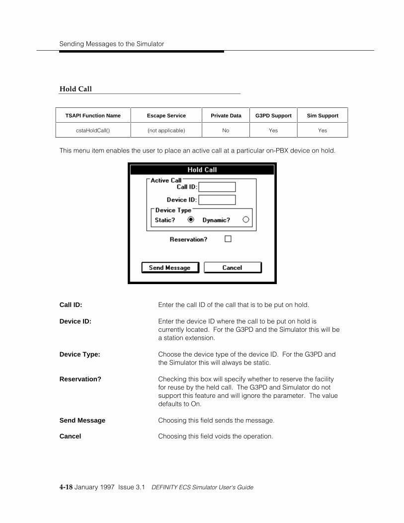
Sending Messages to the Simulator
4-18 January 1997 Issue 3.1 DEFINITY ECS Simulator User‘s Guide
Hold Call
TSAPI Function Name Escape Service Private Data G3PD Support Sim Support
cstaHoldCall() (not applicable) No Yes Yes
This menu item enables the user to place an active call at a particular on-PBX device on hold.
Call ID: Enter the call ID of the call that is to be put on hold.
Device ID: Enter the device ID where the call to be put on hold iscurrently located. For the G3PD and the Simulator this will bea station extension.
Device Type: Choose the device type of the device ID. For the G3PD andthe Simulator this will always be static.
Reservation? Checking this box will specify whether to reserve the facilityfor reuse by the held call. The G3PD and Simulator do notsupport this feature and will ignore the parameter. The valuedefaults to On.
Send Message Choosing this field sends the message.
Cancel Choosing this field voids the operation.

Functions - Call Control Services
DEFINITY ECS Simulator User‘s Guide Issue 3.1 January 1997 4-19
Make Call
TSAPI Function Name Escape Service Private Data G3PD Support Sim Support
cstaMakeCall() (not applicable) Yes Yes Yes
This menu item enables the user to initiate a call from one device to another device. The callingdevice must be an on-PBX extension and for the Simulator it must either have a speakerphonethat can be forced off-hook or it must already be off-hook. Also with the G3PD or Simulator theuser also has the option to include up to 32 bytes of alphanumeric data to be included with thecall that will be delivered in various call event reports and requests.
The first dialog box appears upon selecting the cstaMakeCall item under the “Functions/CallControl Services“ menu.
Calling Device: Enter the extension of the calling party. This must be theextension of an on-PBX station.
Called Device: In Simulator mode this field is either the extension of thestation or ACD group that is being called or a TAC and anynumber. In exerciser mode this is any number that can bedialed by an on-PBX telephone; a station, ACD group orcomplete number that goes off-PBX .
G3PD Private Data Selecting this button to open up a dialog box that allows forentering G3PD Private Data. All fields in the G3PD dialog boxare supported by the G3PD, but in some instances they arenot supported by the Simulator. See specific definitions offields for clarification.
Send Message Choosing this field sends the message.

Sending Messages to the Simulator
4-20 January 1997 Issue 3.1 DEFINITY ECS Simulator User‘s Guide
Cancel Choosing this field voids the operation
The second dialog box appears when the G3PD Private Data button is selected.
Select Make Call Type: Select the type of call to be placed. The G3PD supports allthree types of calls, but the Simulator DLL only supports asimple Make Call and all other types will be handled as aregular make call.
UUI: Enter up to 32 bytes of User to User Information in the Stringfield. If the Protocol Type Selected is IA5 ASCII, then thestring must be entered in alphanumeric format. If theProtocol Type Selected is User Specific, then the string mustbe entered in hexadecimal format This UUI will then beassociated with this call for the duration of the call or until it isreplaced by other UUI. It will be delivered with any deliveredevent or route request associated with the call. UUI can bechanged via route selects, requests, or conference ortransfers.
Dest Route: This private data field specifies the TAC/ARS/AAR informationfor off-PBX destinations. This field is only supported by theG3PD and will be ignored by the Simulator.

Functions - Call Control Services
DEFINITY ECS Simulator User‘s Guide Issue 3.1 January 1997 4-21
Priority? This private data field specifies if the call is a priority call. Ifthe box is checked, then a priority call is placed if the calleddevice is an on-PBX destination. If the called device is an off-PBX destination, then the call will be denied. This field is onlysupported by the G3PD and will be ignored by the Simulator.
Close Choosing this button closes the dialog box and returns theuser to the previous dialog box. Any information entered inthe private data fields will be sent with the message if theSend Message button is selected.

Sending Messages to the Simulator
4-22 January 1997 Issue 3.1 DEFINITY ECS Simulator User‘s Guide
Make Predictive Call
TSAPI Function Name Escape Service Private Data G3PD Support Sim Support
cstaMakePredictiveCall() (not applicable) Yes Yes Yes
This menu item enables the user to originate a Switch-Classified call between two devices. Theservice attempts to create a new call and establish a Connection with the terminating (called)device first. The Make Predictive Call service also provides a CSTA Connection Identifier thatindicates the Connection of the terminating device. The call will be dropped if the call is notanswered after the maximum ring cycle is expired. For the Simulator this means that the user isable to place a call from an ACD to another device (normally an off-PBX number), but itestablishes the destination connection at the far end before the call is established to an agent inthe ACD group. The user also has the option to include up to 32 bytes of alphanumeric data tobe included with the call that will be delivered in various call event reports and requests.The first dialog box appears upon selecting the cstaMakePredictiveCall item under the“Functions/Call Control Services“ menu.
Calling Device: This is an on-PBX number where the call will terminate uponestablishment at the called device. For the Simulator thismust be an administered ACD.
Called Device: This must be a valid on-PBX extension or off-PBX number.The Simulator will only support an off-PBX number for thecalled device.

Functions - Call Control Services
DEFINITY ECS Simulator User‘s Guide Issue 3.1 January 1997 4-23
Allocation State: Choose the condition when the call should attempt to connectto the caller. The G3PD and Simulator only support CallEstablished.
G3PD Private Data Selecting this button to open up a dialog box that allows forentering G3PD Private Data. All fields in the G3PD dialog boxare supported by the G3PD, but in some instances they arenot supported by the Simulator. See specific definitions offields for clarification.
Send Message Choosing this field sends the message.
Cancel Choosing this field voids the operation
The second dialog box appears when the G3PD Private Data button is selected.
Max Rings: This field allows the user to specify how many rings theSimulator/switch should wait before classifying the call asunanswered and dropping the call. For the Simulator this willbe translated to a specified amount of time since there is nota physical phone to ring. The device being called mustanswer the call before this time period expires for the call tocontinue. This field is supported by both the G3PD and theSimulator.
Sending Messages to the Simulator
4-24 January 1997 Issue 3.1 DEFINITY ECS Simulator User‘s Guide
(Answer Treatment) DestRoute
Answer treatment refers to how the call will be handled if ananswering machine is detected at the far end.
Dest Route: This private data field specifies the TAC/ARS/AAR informationfor off-PBX destinations. This field is only supported by theG3PD and will be ignored by the Simulator.
Answer Treatment: If the Answer Detect box is checked then the user mustselect either drop or connect for the treatment of the callwhen an answering machine is detected at the far end. Ifdrop is selected then the call will be dropped once theSimulator/switch has detected the answering machine. Ifconnect is selected then the call will be connected and themake predictive call will proceed as normal.
For the Simulator, trunk groups will be administered as eitherbeing answered by voice or by answering machine. This willallow the Simulator to classify the call appropriately whenAnswering Machine Detection is selected for a makepredictive call.
Priority? Checking this box specifies that a priority call should beplaced. A priority call can only be placed for an on-PBXextension. This field is only supported by the G3PD, and notby the Simulator.
UUI: Enter up to 32 bytes of User to User Information in the Stringfield. If the Protocol Type Selected is IA5 ASCII, then thestring must be entered in alphanumeric format. If theProtocol Type Selected is User Specific, then the string mustbe entered in hexadecimal format. This UUI will then beassociated with this call for the duration of the call or until it isreplaced by other UUI. It will be delivered with any deliveredevent or route request associated with the call. UUI can bechanged via route selects, requests, or conference ortransfers. This field is supported by both the G3PD and theSimulator.
Close Choosing this button closes the dialog box and returns theuser to the previous dialog box. Any information entered inthe private data fields will be sent with the message if theSend Message button is selected.

Functions - Call Control Services
DEFINITY ECS Simulator User‘s Guide Issue 3.1 January 1997 4-25
Pickup Call
TSAPI Function Name Escape Service Private Data G3PD Support Sim Support
cstaPickupCall() (not applicable) No Yes Yes
This menu item enables the user to take a ringing (alerting) call at an on-PBX destination andmove the call to the invoking device specified which must also be an on-PBX destination.
Call ID: Enter the call ID of the connection that is to be picked up.
Device ID: Enter the device ID of the device where the call is currentlyalerting. Note: The Simulator cannot perform a Pickup Call ata VDN; the G3PD can.
Device Type: Choose the device type of the device ID in the connectionthat is currently alerting. For the G3PD and the Simulator thiswill always be static.
New Device ID: Enter the static device ID of the device which is picking upthe original call.
Send Message Choosing this field sends the message.
Cancel Choosing this field voids the operation.

Sending Messages to the Simulator
4-26 January 1997 Issue 3.1 DEFINITY ECS Simulator User‘s Guide
Reconnect Call
TSAPI Function Name Escape Service Private Data G3PD Support Sim Support
cstaReconnectCall() (not applicable) Yes Yes Yes
This menu item enables the user to perform the compound action of clearing an existingconnection and retrieving a previously held call.
Active Call ID: Enter the call ID of the connection that is to be dropped.
Active Device ID: Enter the device ID of the device where the active call islocated.
Active Device Type: Choose the device type of the device ID for the activeconnection. For the G3PD and the Simulator this will alwaysbe static.
Held Call ID: Enter the call ID of the connection that is on hold.

Functions - Call Control Services
DEFINITY ECS Simulator User‘s Guide Issue 3.1 January 1997 4-27
Held Device ID: Enter the device ID of the device where the held call islocated. This should be the same as the Active Device ID.
Held Device Type: Choose the device type of the device ID for the heldconnection. For the G3PD and the Simulator this will alwaysbe static.
G3PD Private Data Select this button to open up a dialog box that allows forentering G3PD Private Data. All fields in the G3PD dialog boxare supported by the G3PD, but in some instances they arenot supported by the Simulator. See specific definitions offields for clarification.
Send Message Choosing this field sends the message.
Cancel Choosing this field voids the operation.
The second dialog box appears when the G3PD Private Data button is selected.

Sending Messages to the Simulator
4-28 January 1997 Issue 3.1 DEFINITY ECS Simulator User‘s Guide
Drop Resource Specifies the resource to be dropped from the call. Theavailable resources are Call Classifier and Tone Generator.The tone generator is any G3 PBX applied denial tone whichis timed by the switch. This field is ignored by the Simulator.
UUI: Enter up to 32 bytes of User to User Information in the Stringfield. If the Protocol Type Selected is IA5 ASCII, then thestring must be entered in alphanumeric format. If theProtocol Type Selected is User Specific, then the string mustbe entered in hexadecimal format . This UUI will then beassociated with this call for the duration of the call or until it isreplaced by other UUI. It will be delivered with any deliveredevent or route request associated with the call. UUI can bechanged via route selects, requests, or conferences ortransfers.
Close Choosing this button closes the dialog box and returns theuser to the previous dialog box. Any information entered inthe private data fields will be sent with the message if theSend Message button is selected.

Functions - Call Control Services
DEFINITY ECS Simulator User‘s Guide Issue 3.1 January 1997 4-29
Retrieve Call
TSAPI Function Name Escape Service Private Data G3PD Support Sim Support
cstaRetrieveCall() (not applicable) No Yes Yes
This menu item enables the user to take a call off hold.
Call ID: Enter the call ID of the connection that is on hold.
Device ID: Enter the device ID of the device where the held call islocated.
Device Type: Choose the device type of the device ID for the heldconnection. For the G3PD and the Simulator this will alwaysbe static.
Send Message Choosing this field sends the message.
Cancel Choosing this field voids the operation.

Sending Messages to the Simulator
4-30 January 1997 Issue 3.1 DEFINITY ECS Simulator User‘s Guide
Transfer Call
TSAPI Function Name Escape Service Private Data G3PD Support Sim Support
cstaTransferCall() (not applicable) No Yes Yes
Choosing this menu item enables the user to transfer a held connection to an active connectionat the same station. A new call ID is assigned to the call by the Simulator. If there is any UUIinformation associated with the calls that are being transferred then if both calls have UUI thenthe UUI from the active call will be associated with the new call. If only one call contains UUIthen that UUI will be associated with the new call.
NOTE:In the simulator, transferring more than one instance of the same extension willgive incorrect results, such as the same party being on the call more thanonce. The G3PD handles this scenario correctly.

Functions - Call Control Services
DEFINITY ECS Simulator User‘s Guide Issue 3.1 January 1997 4-31
Active Call ID: Enter the call ID of the connection that is to be transferred.
Active Device ID: Enter the device ID of the device where the active call islocated.
Active Device Type: Choose the device type of the device ID for the activeconnection. For the G3PD and the Simulator this will alwaysbe static.
Held Call ID: Enter the call ID of the connection that is on hold.
Held Device ID: Enter the device ID of the device where the held call islocated. This should be the same as the Active Device ID.
Held Device Type: Choose the device type of the device ID for the heldconnection. For the G3PD and the Simulator this will alwaysbe static.
Send Message Choosing this field sends the message.
Cancel Choosing this field voids the operation.

Sending Messages to the Simulator
4-32 January 1997 Issue 3.1 DEFINITY ECS Simulator User‘s Guide
Send DTMF Tone
TSAPI Function Name Escape Service Private Data G3PD Support Sim Support
cstaEscapeService() attSendDTMFTone() All Yes Yes
The Send DTMF Tone Service, on behalf of an on-PBX endpoint, sends a sequence of DTMFtones (max 32) to endpoints on the call. The endpoints receiving the DTMF signal can be on-PBX or off-PBX. In order to send the DTMF tones, the call must be in an established state. TheSimulator only does verification of the connection ID and sends back a confirmation event.
Sender Call ID: Enter the call ID of the connection that denotes the sender ofthe DTMF Tones.
Sender Device ID: Enter the device ID of the sender of the tones.
Sender Device Type: This should always be static since this is only supported bythe G3PD and it must originate from an on-PBX extension.
DTMF Tones: Enter the sequence of tones that is to be generated. Theallowed DTMF tones are digits 0-9 and # and *.
Tone Duration: This parameter specifies control for tone duration. It iscurrently not supported by the G3PD, but is reserved forlatter use. Any values put in this field will be ignored.

Functions - Call Control Services
DEFINITY ECS Simulator User‘s Guide Issue 3.1 January 1997 4-33
Pause Duration: This parameter specifies control for pause duration. It iscurrently not supported by the G3PD, but is reserved forlatter use. Any values put in this field will be ignored.
Send Message Choosing this field sends the message.
Cancel Choosing this field voids the operation.

Sending Messages to the Simulator
4-34 January 1997 Issue 3.1 DEFINITY ECS Simulator User‘s Guide
Functions - Escape Services
The Escape Services enable the Simulator to handle DEFINITY ASAI features that use privatedata and private services. In a manner similar to that used by the DEFINITY PBX Driver, theSimulator software formats the private elements, mimics the passing of these elements to andfrom the “PBX“, and maintains status information on state transitions resulting from the use ofprivate elements. The Simulator supports the following Escape Services:
• Split Status, and Agent Login Queries• Collected (Call Prompter) Digits (Delivered Event)• User to User Info• Query Trunk Group• Query Station Status• Query Classifiers• Query Time-of-Day• Query Device Name• Send DTMF Tones• Monitor Stop on Call

Functions - Escape Services
DEFINITY ECS Simulator User‘s Guide Issue 3.1 January 1997 4-35
Escape Service
Use the following procedures only if you want to add private data that is invalid or for otherPBXs. Interfaces are provided for all DEFINITY private data.
1. Select “Run/Private Data” on the main menu. The “Private Data” screen is displayed:
Vendor Enter the authorized vendor character string.
Data (hex) In hexadecimal format, enter the private data to be handledinto the scrollable box.
OK Choosing this field ends the session and saves the data inmemory.
Cancel Choosing this field ends the screen session and does notsave the data.
2. Under the “Functions” item on the main menu, select “Escape Services” and the desiredservice.
If you select “cstaEscapeService()” from the submenu, the “Escape Service” dialog box isdisplayed:

Sending Messages to the Simulator
4-36 January 1997 Issue 3.1 DEFINITY ECS Simulator User‘s Guide
Send Message Choosing this field sends the message.
Cancel Choosing this field voids the operation.

Functions - Escape Services
DEFINITY ECS Simulator User‘s Guide Issue 3.1 January 1997 4-37
Escape Service Confirmation
This confirmation event, which is not supported by either the DEFINITY G3 PBX Driver or theSimulator, is used when a PBX Driver sends an Escape Service request to the client simulator.
Cause Select the desired type of confirmation message from theavailable choices in the scrollable box.
Send Message Choosing this field ends the session and saves the data inmemory.
Cancel Choosing this field ends the screen session and does notsave the data.

Sending Messages to the Simulator
4-38 January 1997 Issue 3.1 DEFINITY ECS Simulator User‘s Guide
Send Private Event
This event is used to send a private event to a PBX Driver. There are no private events definedfor the DEFINITY G3 PBX Driver or the Simulator. Thus, any private events sent will be rejected .
Send Message Choosing this field sends the message.
Cancel Choosing this field voids the operation.

Functions - Maintenance Services
DEFINITY ECS Simulator User‘s Guide Issue 3.1 January 1997 4-39
Functions - Maintenance Services
The Maintenance Services enable the user to set certain status reporting mechanisms and tospecify filters to be used when events are reported.

Sending Messages to the Simulator
4-40 January 1997 Issue 3.1 DEFINITY ECS Simulator User‘s Guide
Change System Status Filter
TSAPI Function Name Escape Service Private Data G3PD Support Sim Support
cstaChangeSysStatFilter() (not applicable) Yes Yes No
This function is used to request a change in the filter options for automatic System Status eventreporting for a specific ACS Stream. It allows the application to specify which System Statusevents it requires.
Filtering Selecting this button will cause the System Status Filteringdialog box to be displayed that will allow you to Select thedesired filter. See System Status Filtering section below.
G3PD Private Data Selecting this button will cause the Change System Status -Filter - Private Data dialog box to be displayed that will allowyou to indicate via a checkbox whether the link status shouldbe provided.
Send Message Choosing this field sends the message.
Cancel Choosing this field voids the operation.

Functions - Maintenance Services
DEFINITY ECS Simulator User‘s Guide Issue 3.1 January 1997 4-41
System Status Request
TSAPI Function Name Escape Service Private Data G3PD Support Sim Support
cstaSysStatReq() (not applicable) No Yes No
This service allows the user to request system status information from the driver/switch domain.
Send Message Choosing this field sends the message.
Cancel Choosing this field voids the operation.

Sending Messages to the Simulator
4-42 January 1997 Issue 3.1 DEFINITY ECS Simulator User‘s Guide
System Status Start
TSAPI Function Name Escape Service Private Data G3PD Support Sim Support
cstaSysStatStart() (not applicable) Yes Yes No
This service allows the user to register for system status event reporting. It can be used by anapplication to automatically receive a CSTASysStatEvent each time the status of thedriver/switch changes.
Filtering Selecting this button will cause the “System Status Filtering“dialog box to appear that will allow for the selection of thedesired filter. See “System Status Filtering“ section below.
G3PD Private Data Selecting this button will cause the “System Status Start -Private Data“ dialog box (see below) to appear that will allowyou to indicate whether the link status should be sent.
Send Message Choosing this field sends the message.
Cancel Choosing this field voids the operation.

Functions - Maintenance Services
DEFINITY ECS Simulator User‘s Guide Issue 3.1 January 1997 4-43
Link Status? Checking this checkbox indicates that the PBX Driver shouldnotify the user of changes in link status.
Close Choosing this field closes the dialog box and returns the userto the previous dialog box. Any information entered in theprivate data fields will be sent with the message if the SendMessage button is selected.

Sending Messages to the Simulator
4-44 January 1997 Issue 3.1 DEFINITY ECS Simulator User‘s Guide
System Status Stop
TSAPI Function Name Escape Service Private Data G3PD Support Sim Support
cstaSysStatStop() (not applicable) No Yes No
This service is used to cancel a previously registered monitor for system status information.
Send Message Choosing this field sends the message.
Cancel Choosing this field voids the operation.

Functions - Maintenance Services
DEFINITY ECS Simulator User‘s Guide Issue 3.1 January 1997 4-45
System Status Event Send
TSAPI Function Name Escape Service Private Data G3PD Support Sim Support
cstaSysStatEventSend() (not applicable) No No No
This service is used to send application system status information in the form of an unsolicitedevent to the driver/switch without a formal request for the information. This status informationcan be sent at any time.
Status Code A list of the possible Status Codes to send for the SystemStatus Event.
Send Message Choosing this field sends the message.
Cancel Choosing this field voids the operation.

Sending Messages to the Simulator
4-46 January 1997 Issue 3.1 DEFINITY ECS Simulator User‘s Guide
System Status Request Confirmation
TSAPI Function Name Escape Service Private Data G3PD Support Sim Support
cstaSysStatReqConf() (not applicable) No No No
This service is used to respond to a CSTASysStatReqEvent unsolicited event from thedriver/switch. It provides the driver/switch with information regarding the status of theapplication.
Status Code A list of the possible Status Codes to send for the SystemStatus Request Confirmation.
Send Message Choosing this field sends the message.
Cancel Choosing this field voids the operation.

Functions - Maintenance Services
DEFINITY ECS Simulator User‘s Guide Issue 3.1 January 1997 4-47
System Status Filtering
If the Filtering button is selected in any of the previous System Status dialog boxes, then thefollowing dialog box will appear and allow you to select the event types you want to be filteredout. In other words, you should mark any check boxes corresponding to the events you do notwish to receive during a system status session.
Set Filter Choosing this field records the filtering information.
No Filter Choosing this field voids the operation.

Sending Messages to the Simulator
4-48 January 1997 Issue 3.1 DEFINITY ECS Simulator User‘s Guide
Functions - Query Services
The Query Services enable a client application to request that the Simulator/Switch provide thestate of device features and static attributes of a device.

Functions - Query Services
DEFINITY ECS Simulator User‘s Guide Issue 3.1 January 1997 4-49
Get API Capabilities
TSAPI Function Name Escape Service Private Data G3PD Support Sim Support
cstaGetAPICaps() (not applicable) No Yes Yes
This function is used by an application to obtain the CSTA API function and event capabilitieswhich are supported by the driver to which the stream is opened. If a capability is supported,then any corresponding confirmation event is also supported.
Send Message Choosing this field sends the message.
Cancel Choosing this field voids the operation.

Sending Messages to the Simulator
4-50 January 1997 Issue 3.1 DEFINITY ECS Simulator User‘s Guide
Get Device List
TSAPI Function Name Escape Service Private Data G3PD Support Sim Support
cstaGetDeviceList() (not applicable) No (not applicable) (not applicable)
This function is processed by the Telephony Server, and the user record associated with thelogin ID that opened the exerciser stream is used to provide data requested by the command.In the Get Device List command, the administered permission level and the list type requestedin the message (monitor, call control or route to) are used to compile a list of devices that maybe accessed on the opened stream.
The list of devices is returned in a confirmation message. If there are more than twenty devicesin the list, the initial confirmation message contains the first twenty and an index to be used toobtain the next set of devices. This index must be returned in subsequent requests to get theentire list.
Index: The index field is used to indicate where in the list of devicesthe Telephony Server should start searching. A value of (-1)says to start at the beginning. The index value returned in theconfirmation should be used for subsequent messages.When this value is (-1), the list of devices is complete.

Functions - Query Services
DEFINITY ECS Simulator User‘s Guide Issue 3.1 January 1997 4-51
Level: This is the type of device list desired. Select from thefollowing types:
Home WorktopAway WorktopDevice/Device MonitorCall/Device MonitorCall ControlRoutingCall/Call Monitor
Send Message Choosing this field sends the message.
Cancel Choosing this field voids the operation.

Sending Messages to the Simulator
4-52 January 1997 Issue 3.1 DEFINITY ECS Simulator User‘s Guide
Query Call Monitor
TSAPI Function Name Escape Service Private Data G3PD Support Sim Support
cstaQueryCallMonitor() (not applicable) No (not applicable) (not applicable)
This function is processed by the Telephony Server. The user record associated with the loginID that opened the stream is used to provide data requested by the command. In the QueryCall Monitor command, the class of service option for call/call monitoring is returned. If it ispermitted, the confirmation message contains true. If not, false is displayed.
There is no required data for this message.
Send Message Choosing this field sends the message.
Cancel Choosing this field voids the operation.

Functions - Query Services
DEFINITY ECS Simulator User‘s Guide Issue 3.1 January 1997 4-53
Query Agent State
TSAPI Function Name Escape Service Private Data G3PD Support Sim Support
cstaQueryAgentState() (not applicable) Yes Yes Yes
The Query Agent State command queries the Simulator (or PBX) for the current state of aparticular agent.
Device ID: Enter the extension of the device that is to be queried for itsagent state.
G3PD Private Data Select this button to open up a dialog box that allows forentering G3PD Private Data. All fields in the G3PD dialog boxare supported by the G3PD, but in some instances they arenot supported by the Simulator. See specific definitions offields for clarification.
Send Message Choosing this field sends the message.
Cancel Choosing this field voids the operation.

Sending Messages to the Simulator
4-54 January 1997 Issue 3.1 DEFINITY ECS Simulator User‘s Guide
The second dialog box appears when the G3PD Private Data button is selected.
ACD Split Extension Enter the split extension to which the agent is logged in. Thisfield is ignored by the Simulator.
Close Choosing this button closes the dialog box and returns theuser to the previous dialog box. The code selected will besent with the message if the Send Message button isselected.

Functions - Query Services
DEFINITY ECS Simulator User‘s Guide Issue 3.1 January 1997 4-55
Query Device Information
TSAPI Function Name Escape Service Private Data G3PD Support Sim Support
cstaQueryDeviceInfo() (not applicable) No Yes Yes
The Query Device Information command queries the Simulator (or the PBX in exerciser mode)for the class and type of a device. The class will be one of the following: voice, data, image, orother. The type will be either station, ACD, ACD Group, or other.
Device ID: Enter the extension of the device that is to be queried forinformation. Note: The Query Device Information function isnot supported on TACs in the Simulator.
Send Message Choosing this field sends the message.
Cancel Choosing this field voids the operation.

Sending Messages to the Simulator
4-56 January 1997 Issue 3.1 DEFINITY ECS Simulator User‘s Guide
Query Do Not Disturb
TSAPI Function Name Escape Service Private Data G3PD Support Sim Support
cstaQueryDoNotDisturb() (not applicable) No Yes Yes
The Query Do Not Disturb command queries the Simulator (or PBX) for the current state of theDo Not Disturb feature (also referred to as Send All Calls - SAC, for the DEFINITY G3) on aspecific device. The station must have the Do Not Disturb feature administered for this query tosucceed.
Device ID: Enter the extension of the station whose Do Not Disturb statusis to be queried.
Send Message Choosing this field sends the message.
Cancel Choosing this field voids the operation.

Functions - Query Services
DEFINITY ECS Simulator User‘s Guide Issue 3.1 January 1997 4-57
Query Forwarding
TSAPI Function Name Escape Service Private Data G3PD Support Sim Support
cstaQueryForwarding() (not applicable) No Yes Yes
The Query Forwarding command queries the Simulator (or PBX) for the current state of theForwarding feature on a specific device. The station must have the Forwarding featureadministered for this query to succeed.
Device ID: Enter the extension of the station whose Forwarding status isto be queried.
Send Message Choosing this field sends the message.
Cancel Choosing this field voids the operation.

Sending Messages to the Simulator
4-58 January 1997 Issue 3.1 DEFINITY ECS Simulator User‘s Guide
Query Last Number
TSAPI Function Name Escape Service Private Data G3PD Support Sim Support
cstaQueryLastNumber() (not applicable) No No No
The Query Last Number command queries the PBX for the last number dialed on a specificdevice.
Device ID: Enter the extension of the station whose Last Number Dialedis to be queried.
Send Message Choosing this field sends the message.
Cancel Choosing this field voids the operation.

Functions - Query Services
DEFINITY ECS Simulator User‘s Guide Issue 3.1 January 1997 4-59
Query Message Waiting Indicator
TSAPI Function Name Escape Service Private Data G3PD Support Sim Support
cstaQueryMsgWaitingInd() (not applicable) No Yes Yes
The Query Message Waiting Indicator command queries the Simulator DLL (or PBX) for thecurrent state of the Message Waiting Indicator. The station must have a Message WaitingIndicator for this query to succeed.
Device ID: Enter the extension of the station whose message waitingindicator is to be queried.
Send Message Choosing this field sends the message.
Cancel Choosing this field voids the operation.
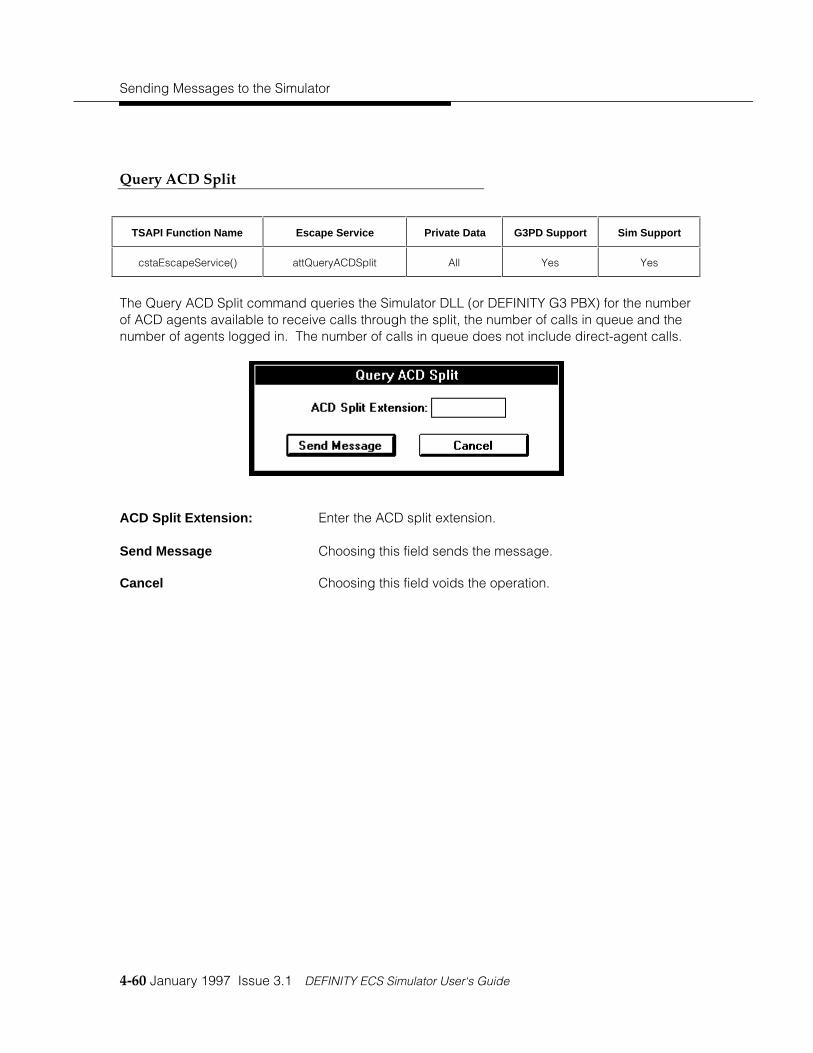
Sending Messages to the Simulator
4-60 January 1997 Issue 3.1 DEFINITY ECS Simulator User‘s Guide
Query ACD Split
TSAPI Function Name Escape Service Private Data G3PD Support Sim Support
cstaEscapeService() attQueryACDSplit All Yes Yes
The Query ACD Split command queries the Simulator DLL (or DEFINITY G3 PBX) for the numberof ACD agents available to receive calls through the split, the number of calls in queue and thenumber of agents logged in. The number of calls in queue does not include direct-agent calls.
ACD Split Extension: Enter the ACD split extension.
Send Message Choosing this field sends the message.
Cancel Choosing this field voids the operation.

Functions - Query Services
DEFINITY ECS Simulator User‘s Guide Issue 3.1 January 1997 4-61
Query Agent Login
TSAPI Function Name Escape Service Private Data G3PD Support Sim Support
cstaEscapeService() attQueryAgentLogin All Yes Yes
The Query Agent Login command queries the Simulator (or DEFINITY G3 PBX) for the extensionof each ACD agent logged into the ACD Split.
ACD Split Extension: Enter the ACD split extension.
Send Message Choosing this field sends the message.
Cancel Choosing this field voids the operation.

Sending Messages to the Simulator
4-62 January 1997 Issue 3.1 DEFINITY ECS Simulator User‘s Guide
Query Call Classifier
TSAPI Function Name Escape Service Private Data G3PD Support Sim Support
cstaEscapeService() attQueryCallClassifier() All Yes Yes
This command queries the DEFINITY G3 PBX for the number of idle and in-use TN744 ports.The in-use number is a snapshot of the call classifier port usage. For the Simulator, the numberof in-use and idle trunk members is returned.
Send Message Choosing this field sends the message.
Cancel Choosing this field voids the operation.

Functions - Query Services
DEFINITY ECS Simulator User‘s Guide Issue 3.1 January 1997 4-63
Query Device Name
TSAPI Function Name Escape Service Private Data G3PD Support Sim Support
cstaEscapeService() attQueryDeviceName() All Yes Yes
The Query Device Name command queries the Simulator (or the PBX in exerciser mode) for theadministered name of a device.
Device ID: Enter the extension of the device that is to be queried.
Send Message Choosing this field sends the message.
Cancel Choosing this field voids the operation.

Sending Messages to the Simulator
4-64 January 1997 Issue 3.1 DEFINITY ECS Simulator User‘s Guide
Query Station Status
TSAPI Function Name Escape Service Private Data G3PD Support Sim Support
cstaEscapeService() attQueryStationStatus() All Yes Yes
The Query Station Status command provides the idle and/or busy state of the station. The busystate is returned if the station is active with a call. The idle state is returned if the station is notactive an any call.
Device ID: Enter the extension number of the station to query. Thestation must be an on-PBX station.
Send Message Choosing this field sends the message.
Cancel Choosing this field voids the operation.

Functions - Query Services
DEFINITY ECS Simulator User‘s Guide Issue 3.1 January 1997 4-65
Query Time of Day
TSAPI Function Name Escape Service Private Data G3PD Support Sim Support
cstaEscapeService() attQueryTimeOfDay() All Yes Yes
The Query Time Of Day service provides the DEFINITY switch information for the year, month,day, hour, minute, and second. The Simulator returns the time of day of the server.
Send Message Choosing this field sends the message.
Cancel Choosing this field voids the operation.

Sending Messages to the Simulator
4-66 January 1997 Issue 3.1 DEFINITY ECS Simulator User‘s Guide
Query Trunk Group
TSAPI Function Name Escape Service Private Data G3PD Support Sim Support
cstaEscapeService() attQueryTrunkGroup() All Yes Yes
The Query Trunk Group command provides the number of idle trunks and the number of in-usetrunks. The sum of the idle and in-use trunks provides the number of trunks in service.
Device ID: Enter the TAC associated with the trunk group that is to bequeried.
Send Message Choosing this field sends the message.
Cancel Choosing this field voids the operation.

Functions - Routing Services
DEFINITY ECS Simulator User‘s Guide Issue 3.1 January 1997 4-67
Functions - Routing Services
The CSTA functions in this menu allow the user to register an application as a routing server andto provide the switch/Simulator with call routing information on a call-by-call basis:

Sending Messages to the Simulator
4-68 January 1997 Issue 3.1 DEFINITY ECS Simulator User‘s Guide
Route System Parameters
This dialog box allows the user of the Client Simulator Interface to choose whether or not to havethe application respond automatically to any route requests that it may receive. To receiveroute requests, the Client Simulator Interface must have previously registered as a routingserver. If the Client Simulator Interface is registered as a routing server and the AutomaticResponse to Route Requests is desired, then the Route Tables must be appropriately filled outso that a route selection can be determined and sent back to the requesting routing device.
Automatic Response toRouteRequests?
Check this box if you wish to have the Client SimulatorInterface automatically respond with Route Select to anyRoute Requests that it may receive based on a previous routeregistration with a routing device. If you do not check thisbox, and certain conditions are true, the system will displaythe Route Request Response dialog box. For moreinformation, see the “Manual Routing Dialog“ section below.
All route select information that is sent back is based on userinput to the routing tables described in the Route Tablessection below.
OK Choosing this sets the Automatic Response to RouteRequests parameter.
Cancel Choosing this field voids the operation.

Functions - Routing Services
DEFINITY ECS Simulator User‘s Guide Issue 3.1 January 1997 4-69
Route Tables (Automatic Routing Feature)
The Route Table forms are used when you check the Automatic Response to Route Requestscheckbox.
Device ID (Current Route): Specifies the current destination of the call. This is the ACDextension number first entered by the call.
Dest 1, 2, and 3: Enter the extension(s) of the device(s) to which the call is tobe routed. The G3PD and the Simulator do not support theSecond Destination and Third Destination.
Registration ID The registration ID that was returned by the previouslyexecuted Route Register Request command.
Route ID The unique identifier for a call within a routing session.
Edit Choosing this button opens the Route Table Form dialog boxon an entry to edit.
Create Choosing this button opens the Route Table Form dialog box.

Sending Messages to the Simulator
4-70 January 1997 Issue 3.1 DEFINITY ECS Simulator User‘s Guide
Close Choosing this button closes the dialog box and returns theuser to the previous dialog box. The code selected will besent with the message if the Send Message button isselected.
Selecting the Create button displays a second window.
(Routing Device) Device ID The extension of the device on the switch that is making theroute request of the application providing routing service.
Device ID Enter the appropriate extension.
Device ID Type Select the appropriate device ID type from the drop down list.
First, Second, and ThirdDestination
The extension(s) of the device(s) to which the call is to berouted. The G3PD and the Simulator do not support theSecond Destination and Third Destination.
Send a “Route Used“ Event? Check the box if the PBX/Simulator is to send this message tothe routing server application.
Setup Info (Hex) Enter the desired setup information in hexadecimal format.

Functions - Routing Services
DEFINITY ECS Simulator User‘s Guide Issue 3.1 January 1997 4-71
G3PD Private Data Select this button to open up the Route Table Form - PrivateData dialog box that allows for entering G3PD Private Data.All fields in the G3PD dialog box are supported by the G3PD,but in some instances they are not supported by theSimulator. See specific definitions of fields for clarification.
OK Choosing this field enters the information for the currentsession. To save for later sessions the Save option must beperformed.
Cancel Choosing this field voids the operation.
Delete Choosing this field deletes the entry.
Selecting the G3PD Private Data button displays a third window.
Dest Route: This private data field specifies the TAC/ARS/AAR informationfor off-PBX destinations. This field is only supported by theG3PD and will be ignored by the Simulator.

Sending Messages to the Simulator
4-72 January 1997 Issue 3.1 DEFINITY ECS Simulator User‘s Guide
Direct Agent Call Split: Specifies the extension of the ACD agent’s split extension forDirect Agent call routing. This field is ignored by theSimulator.
Priority? Checking this box specifies that a priority call should beplaced. A priority call can only be placed for an on-PBXextension. This field is only supported by the G3PD, and notby the Simulator.
User Entered Code: This field can be filled in with a code/digits to allow theapplication to send code/digits with the routed call. Thesecode/digits are treated as dial-ahead digits for the call, whichare stored in a dial-ahead buffer. They can be collectedusing the collect digits vector command(s) on the switch.The User Entered Code and the Collect Code are mutuallyexclusive. If User Entered Code is present, Collect Codecannot be present. A NULL parameter specifies no userentered code.
(Collect Code) Timeout: Enter the timeout length for the Collect Code request. Thisparameter in combination with the next parameter allow theapplication to request a DTMF tone detector to be connectedto the routed call and to detect and collect caller enteredcode/digits. The Collect Code is mutually exclusive with theUser Entered Code above. This field is ignored by theSimulator.
(Collect Code) Number ofDigits
Enter the number of digits to be collected. This parameter incombination with the previous parameter allow the applicationto request a DTMF tone detector to be connected to therouted call and to detect and collect caller enteredcode/digits. The Collect Code is mutually exclusive with theUser Entered Code above. This field is ignored by theSimulator.
(Specific Event) Answer: The amount of time the switch should wait for the far end toanswer.
(Specific Event) Disconnect: The amount of time the switch should for the far end toanswer before disconnecting the call.

Functions - Routing Services
DEFINITY ECS Simulator User‘s Guide Issue 3.1 January 1997 4-73
UUI: Enter up to 32 bytes of User to User Information in the Stringfield. If the Protocol Type Selected is IA5 ASCII, then thestring must be entered in alphanumeric format. If theProtocol Type Selected is User Specific, then the string mustbe entered in hexadecimal format This UUI will then beassociated with this call for the duration of the call or until it isreplaced by other UUI. It will be delivered with any deliveredevent or route request associated with the call. UUI can bechanged via route selects, requests, or conference ortransfers.
Close Choosing this button closes the dialog box and returns theuser to the previous dialog box. The code Selected will besent with the message if the Send Message button isselected.

Sending Messages to the Simulator
4-74 January 1997 Issue 3.1 DEFINITY ECS Simulator User‘s Guide
Manual Routing Dialog
The purpose of the Route Request Response dialog box is to supply necessary information tothe Driver via a manual routing dialog.
The Route Request Response dialog box is displayed when: 1) the Client Simulator is the routingserver AND 2) the PBX Driver sends a Route Request for a specific device, AND either of thefollowing is true:
a. Automatic Routing has not been selected OR
b. Automatic Routing has been selected but no routing administration has been entered forthe device for which the Client Simulator is the registered routing device.
(Application Response toRequest) Route Selected:
Pressing this button is analogous to selecting thecstaRouteSelect item on the ÕFunctions/Routing ServicesÖ
menu. The route select function provides a destination to theSimulator or switch/driver in response to a cstaRouteRequestEvent for a call.
(Application Response toRequest) Route Ended byApplication
Pressing this button is analogous to selecting thecstaRouteEnd item on the ÕFunctions/Routing ServicesÖ menu.The route end function enables the application to send aroute end message with the cause value you select from thechoices in the resulting drop down box.

Functions - Routing Services
DEFINITY ECS Simulator User‘s Guide Issue 3.1 January 1997 4-75
(No Application Response)Mimic Route Ended by PBX:
(Simulator mode only) Pressing this button is analogous toselecting the ÕPBX/Route EndÖ menu item. Doing so enablesthe Simulator to mimic a route end action by the PBX.

Sending Messages to the Simulator
4-76 January 1997 Issue 3.1 DEFINITY ECS Simulator User‘s Guide
Route End
TSAPI Function Name Escape Service Private Data G3PD Support Sim Support
cstaRouteEnd() (not applicable) No Yes Yes
This menu item allows the user to cancel an active routing dialog for a call.
Registration ID: Enter the registration ID that was returned by the previouslyexecuted Route Register Request Command.
Cross Reference ID: Enter the routing dialog cross-reference ID that is to beended.
Cause: From the available options in the scrollable list, enter the errorvalue that indicates the reason why the routing dialog isending.
Send Message Choosing this field sends the message.
Cancel Choosing this field voids the operation.

Functions - Routing Services
DEFINITY ECS Simulator User‘s Guide Issue 3.1 January 1997 4-77
Route Register Cancel
TSAPI Function Name Escape Service Private Data G3PD Support Sim Support
cstaRouteRegisterCancel() (not applicable) No Yes Yes
This menu item allows the user to cancel a previously registered routing server session. Thisrequest terminates the routing session and the application receives no further routing messagesfor that session.
Registration ID: Enter the registration ID that was returned by the previouslyexecuted Route Register Request Command.
Send Message Choosing this field sends the message.
Cancel Choosing this field voids the operation.

Sending Messages to the Simulator
4-78 January 1997 Issue 3.1 DEFINITY ECS Simulator User‘s Guide
Route Register
TSAPI Function Name Escape Service Private Data G3PD Support Sim Support
cstaRouteRegisterReq() (not applicable) No Yes Yes
This menu item allows the user to register an application as a routing server such that it willreceive routing requests on a call-by-call basis. The register must be done by the applicationbefore it will receive any route requests from the switch/driver or Simulator.
Device ID: Enter the device ID of the routing device.
Send Message Choosing this field sends the message.
Cancel Choosing this field voids the operation.

Functions - Routing Services
DEFINITY ECS Simulator User‘s Guide Issue 3.1 January 1997 4-79
Route Select
TSAPI Function Name Escape Service Private Data G3PD Support Sim Support
cstaRouteSelect (not applicable) Yes Yes Yes
The route select menu item allows the user to provide a destination to the switch in response toa cstaRouteRequestEvent for a call. This function can only be used if the Automatic Responseto Route Requests system parameter is not set. If the client Simulator interface has theAutomatic Response to Route Requests system parameter set then the route select will beautomatically sent upon receipt of the route request. If a route select is sent without acorresponding route request it will be rejected by the Simulator or switch/driver.
Registration ID: Enter the registration ID that was returned by the previouslyexecuted Route Register Request Command.
Cross Reference ID: Enter the routing dialog cross-reference ID that was providedin the Route Request event.
Remaining Retries: These fields (Specify Count, Count, No List, No Count)specify the number of times that the application is willing toreceive a CSTARouteRequestEvent for this call in case theswitch needs to request an alternate route. These fields arenot supported by the G3PD or the Simulator.

Sending Messages to the Simulator
4-80 January 1997 Issue 3.1 DEFINITY ECS Simulator User‘s Guide
Route Selected: Enter the destination for the call. It can either be an on-PBXnumber or an off-PBX number.
Send a Route Used Event? Check this box to indicate a request to receive aCSTARouteUsedEvent for the call. Note that if specified forthe G3PD or Simulator, the same destination information thatis specified in the Destination Device ID field will be returned.
Setup Info (hex): Enter a revised ISDN call setup message that the switch willuse to route the call. This field is not supported by the G3PDor the Simulator.
G3PD Private Data Select this button to open up a dialog box that allows forentering G3PD Private Data. All fields in the G3PD dialog boxare supported by the G3PD, but in some instances they arenot supported by the Simulator. See specific definitions offields for clarification.
Send Message Choosing this field sends the message.
Cancel Choosing this field voids the operation.
Selecting the G3PD Private Data button displays a second window.

Functions - Routing Services
DEFINITY ECS Simulator User‘s Guide Issue 3.1 January 1997 4-81
Dest Route: This private data field specifies the TAC/ARS/AAR informationfor off-PBX destinations. This field is only supported by theG3PD and will be ignored by the Simulator.
Direct Agent Call Split: Specifies the extension of the ACD agent’s split extension forDirect Agent call routing. This field is ignored by theSimulator.
Priority? Checking this box specifies that a priority call should beplaced. A priority call can only be placed for an on-PBXextension. This field is only supported by the G3PD, and notby the Simulator.
User Entered Code: This field can be filled in with a code/digits to allow theapplication to send code/digits with the routed call. Thesecode/digits are treated as dial-ahead digits for the call, whichare stored in a dial-ahead buffer. They can be collectedusing the collect digits vector command(s) on the switch.The User Entered Code and the Collect Code are mutuallyexclusive. If User Entered Code is present, Collect Codecannot be present. A NULL parameter specifies no userentered code.
(Collect Code) Timeout: Enter the timeout length for the Collect Code request. Thisparameter in combination with the next parameter allow theapplication to request a DTMF tone detector to be connectedto the routed call and to detect and collect caller enteredcode/digits. The Collect Code is mutually exclusive with theUser Entered Code above. This field is ignored by theSimulator.
(Collect Code) Number ofDigits
Enter the number of digits to be collected. This parameter incombination with the previous parameter allow the applicationto request a DTMF tone detector to be connected to therouted call and to detect and collect caller enteredcode/digits. The Collect Code is mutually exclusive with theUser Entered Code above. This field is ignored by theSimulator.
(Specific Event) Answer: The amount of time the switch should wait for the far end toanswer.
(Specific Event) Disconnect: The amount of time the switch should for the far end toanswer before disconnecting the call.

Sending Messages to the Simulator
4-82 January 1997 Issue 3.1 DEFINITY ECS Simulator User‘s Guide
UUI: Enter up to 32 bytes of User to User Information in the Stringfield. If the Protocol Type Selected is IA5 ASCII, then thestring must be entered in alphanumeric format. If theProtocol Type Selected is User Specific, then the string mustbe entered in hexadecimal format This UUI will then beassociated with this call for the duration of the call or until it isreplaced by other UUI. It will be delivered with any deliveredevent or route request associated with the call. UUI can bechanged via route selects, requests, or conference ortransfers.
Close Choosing this button closes the dialog box and returns theuser to the previous dialog box. Any information entered inthe private data fields will be sent with the message if theSend Message button is selected.

Functions - Set Feature Services
DEFINITY ECS Simulator User‘s Guide Issue 3.1 January 1997 4-83
Functions - Set Feature Services
The CSTA functions in this menu allow the user to set certain states on the Simulator/PBX:

Sending Messages to the Simulator
4-84 January 1997 Issue 3.1 DEFINITY ECS Simulator User‘s Guide
Set Agent State
TSAPI Function Name Escape Service Private Data G3PD Support Sim Support
cstaSetAgentState() (not applicable) Yes Yes Yes
The Set Agent State command sets the current work mode of an agent to any one of thepredefined agent states. These states affect whether an agent in an ACD group will receivecalls through the ACD. For the Simulator and G3PD, when logging in an agent, the defaultmode will be Not Ready. To change this, another Set Agent State command must be performedimmediately after logging the agent into the ACD.
Device ID: Enter the device ID of the agent station. If using theSimulator, the station must be administered as being anagent station.
Agent ID: Enter the Agent login identifier for the ACD agent. For theG3PD, this parameter is optional unless the Agent Mode isLog In; then it is mandatory. The Simulator does not supportthis field and it will be ignored.
Agent Group: Enter the ACD agent split to login, logout or change the workmode. This parameter is optional for the G3PD and is notsupported by the Simulator.

Functions - Set Feature Services
DEFINITY ECS Simulator User‘s Guide Issue 3.1 January 1997 4-85
Agent Password: This field should be filled in with the password associated withthe particular agent specified above. This parameter needonly be filled in for the G3PD when the Agent Mode is login.This field is ignored by the Simulator.
Agent Mode Select the agent mode to which the specified agent will beset.
G3PD Private Data Select this button to open up a dialog box that allows forentering G3PD Private Data. All fields in the G3PD dialog boxare supported by the G3PD, but in some instances they arenot supported by the Simulator. See specific definitions offields for clarification.
Send Message Choosing this field sends the message.
Cancel Choosing this field voids the operation.
Selecting the G3PD Private Data button displays a second window.
Initial Work Mode Enter the work mode for the agent based on the Agent Modeentered. This is supported by the G3PD and the Simulator.
Close Choosing this button closes the dialog box and returns theuser to the previous dialog box. The code Selected will besent with the message if the Send Message button isselected.

Sending Messages to the Simulator
4-86 January 1997 Issue 3.1 DEFINITY ECS Simulator User‘s Guide
Set Do Not Disturb
TSAPI Function Name Escape Service Private Data G3PD Support Sim Support
cstaSetDoNotDisturb() (not applicable) No Yes Yes
The Do Not Disturb command instructs a station to send all incoming calls to its covering stationimmediately. For this request to be successful in the Simulator, the station must be administeredwith coverage enabled and a send-calls button.
Device ID: Enter the device ID of the station on which to set the Do NotDisturb feature.
Do Not Disturb? Check this field if Do Not Disturb is to be enabled at thisstation. Clear the field if the feature is to be disabled.
Send Message Choosing this field sends the message.
Cancel Choosing this field voids the operation.

Functions - Set Feature Services
DEFINITY ECS Simulator User‘s Guide Issue 3.1 January 1997 4-87
Set Forwarding
TSAPI Function Name Escape Service Private Data G3PD Support Sim Support
cstaSetForwarding() (not applicable) No Yes Yes
The Set Forwarding command turns on forwarding at the designated station so that all incomingcalls to that station are immediately sent to the forwarding station. The forwarding station mayalso be changed using this request. For the Simulator, the station must be administered withforwarding enabled (see chapter 3) if this request is to be successful.
Device ID: Enter the extension number of the forwarding station.
Forwarding Type: Choose the type of forwarding to be set for the device. The G3PDand the Simulator only support IMMEDIATE. Any other type will berejected.
Forwarding On? Check if forwarding is to be turned on. Leave blank if the field is tobe turned off. The forwarding type is defaulted to immediate whichis the only type supported by the DEFINITY G3 PBX.
Forwarding Extension: The device ID to which calls are to be forwarded.
Send Message Choosing this field sends the message.

Sending Messages to the Simulator
4-88 January 1997 Issue 3.1 DEFINITY ECS Simulator User‘s Guide
Cancel Choosing this field voids the operation.

Functions - Set Feature Services
DEFINITY ECS Simulator User‘s Guide Issue 3.1 January 1997 4-89
Set Message Waiting Indicator
TSAPI Function Name Escape Service Private Data G3PD Support Sim Support
cstaSetMsgWaitingInd() (not applicable) No Yes Yes
The Set Message Waiting command turns the message waiting indicator on a station either onor off.
Device ID: Enter the device ID of the station whose message waitingindicator is to be set.
Message Waiting IndicatorOn?
Check this field if the indicator is to be turned on; a blank fieldturns off the indicator.
Send Message Choosing this field sends the message.
Cancel Choosing this field voids the operation.

Sending Messages to the Simulator
4-90 January 1997 Issue 3.1 DEFINITY ECS Simulator User‘s Guide
Functions - Snapshot Services
The CSTA functions in this menu allow the user to obtain a "snapshot" status of calls and deviceson the Simulator/PBX:

Functions - Snapshot Services
DEFINITY ECS Simulator User‘s Guide Issue 3.1 January 1997 4-91
Snapshot Call
TSAPI Function Name Escape Service Private Data G3PD Support Sim Support
cstaSnapshotCallReq() (not applicable) No Yes Yes
This menu item allows the user to receive a snapshot of information for a given call ID. It willreturn the devices associated with the given call and the connection state for each device.
Call ID: Enter the call ID of the call that is to have a snapshot taken.
Device ID: Enter the device ID from the connection ID that identifies thecall.
Device Type: Enter the device type that is provided in the connection ID.
Send Message Choosing this field sends the message.
Cancel Choosing this field voids the operation.

Sending Messages to the Simulator
4-92 January 1997 Issue 3.1 DEFINITY ECS Simulator User‘s Guide
Snapshot Device
TSAPI Function Name Escape Service Private Data G3PD Support Sim Support
cstaSnapshotDeviceReq() (not applicable) No Yes Yes
This menu item allows the user to receive a snapshot of information for a given device. It willreturn a list of calls associated with the given device and the connection state of each of thosecalls at that device.
Device ID: Enter the device ID of the device that is to have its snapshottaken.
Send Message Choosing this field sends the message.
Cancel Choosing this field voids the operation.

Functions - Status Reporting Services
DEFINITY ECS Simulator User‘s Guide Issue 3.1 January 1997 4-93
Functions - Status Reporting Services
These CSTA functions allow the user to establish, end, and modify monitoring sessions on CSTAobjects such as devices and calls. They include the functions in the following sub-menu:

Sending Messages to the Simulator
4-94 January 1997 Issue 3.1 DEFINITY ECS Simulator User‘s Guide
Change Monitor Filter
TSAPI Function Name Escape Service Private Data G3PD Support Sim Support
cstaChangeMonitorFilter() (not applicable) Yes Yes Yes
Choosing this menu item allows the user to specify which unsolicited events should be sent backto the application and which ones should be filtered out.
Cross Reference ID: This is the number that identifies the specific monitoringsession for which the filtering is to be changed. The crossreference ID is returned in the confirmation message for theset device monitor, the set call monitor by device, or the setcall monitor request.
Filtering Select this button to change the filtering of events. Seeexplanation in Filter Selection section below.
G3PD Private Filter Select this button to change the filtering of G3 Private events.See explanation in “G3PD Private Filter Selection” in the nextsection.
Send Message Choosing this field sends the message.
Cancel Choosing this field voids the operation.

Functions - Status Reporting Services
DEFINITY ECS Simulator User‘s Guide Issue 3.1 January 1997 4-95
Monitor Call
TSAPI Function Name Escape Service Private Data G3PD Support Sim Support
cstaMonitorCall() (not applicable) Yes Yes Yes
This menu item allows you to monitor a particular call. The call ID should be obtained fromeither a monitoring session of a device or from a make call function.
Call ID: Enter the Call ID of the call to be monitored.
Device ID: Enter the Device ID from the Connection ID of the call to bemonitored.
Filtering Select this button to change the filtering of events. Seeexplanation in Filter Selection section at the end of thissection.
G3PD Private Filter Select this button to change the filtering of events when usingG3PD Private Data .
Send Message Choosing this field sends the message.
Cancel Choosing this field voids the operation.

Sending Messages to the Simulator
4-96 January 1997 Issue 3.1 DEFINITY ECS Simulator User‘s Guide
Monitor Calls Via Device
TSAPI Function Name Escape Service Private Data G3PD Support Sim Support
cstaMonitorCallsViaDevice() (not applicable) Yes Yes Yes
This menu item allows the user to monitor what happens to a call once it reaches a particulardevice. The Simulator DLL supports this feature only for ACD groups. That is, this type ofmonitor may be set on an ACD group extension. When an incoming call arrives at this ACDgroup, monitoring begins. Events are reported as normal for all actions taken on this call.
Device ID: Enter the device ID to monitor calls on. For the G3PD thismust be a VDN, and for the Simulator it must be anadministered ACD.
Filtering Select this button to change the filtering of events. Seeexplanation in Filter Selection section at the end of thissection.
G3PD Private Filter Select this button to change the filtering of events when usingG3PD Private Data.
Send Message Choosing this field sends the message.
Cancel Choosing this field voids the operation.

Functions - Status Reporting Services
DEFINITY ECS Simulator User‘s Guide Issue 3.1 January 1997 4-97
Monitor Device
TSAPI Function Name Escape Service Private Data G3PD Support Sim Support
cstaMonitorDevice() (not applicable) Yes Yes Yes
This menu item allows the user to enable device monitoring for a specific device and to changethe filter to specify which events should be filtered out.
Device ID: Enter the device ID of the device to be monitored.
Filtering Select this button to change the filtering of events. Seeexplanation in “Filter Selection” at the end of this section.
G3PD Private Filter Select this button to change the filtering of events when usingG3PD Private Data.
Send Message Choosing this field sends the message.
Cancel Choosing this field voids the operation.

Sending Messages to the Simulator
4-98 January 1997 Issue 3.1 DEFINITY ECS Simulator User‘s Guide
Monitor Stop
TSAPI Function Name Escape Service Private Data G3PD Support Sim Support
cstaMonitorStop() (not applicable) No Yes Yes
Choosing this menu item allows the user to terminate a monitoring session of any type (bydevice, by call, or by calls via device).
Cross Reference ID: This is the number that identifies the specific monitor that isto be terminated. The cross-reference ID is returned in theconfirmation message for the Set Device Monitor, the Set CallMonitor by Device, or the Set Call Monitor request.
Send Message Choosing this field sends the message.
Cancel Choosing this field voids the operation.

Functions - Status Reporting Services
DEFINITY ECS Simulator User‘s Guide Issue 3.1 January 1997 4-99
Monitor Stop on Call
TSAPI Function Name Escape Service Private Data G3PD Support Sim Support
cstaEscapeService() attMonitorStopOnCall All Yes Yes
An application uses the Monitor Stop On Call Service to stop call event reports for a specific callreported by a cstaMonitorCall, cstaMonitorDevice, or cstaMonitorCallsViaDevice service when itno longer has an interest in that call.
Cross Reference ID The Cross-Reference ID that was returned in a previouscsta MonitorConfEvent of this session.
Call ID The unique identifier of the call being monitored
Device ID The extension of the device with the call.
Device Type Static? Indicates if the device identifier is one that is stable andunique over time; that is, it remains constant and unique overcalls.
Device Type Dynamic? Indicates if the device identifier is one that changed by theswitch over time.
Send Message Choosing this field sends the message.
Cancel Choosing this field voids the operation.

Sending Messages to the Simulator
4-100 January 1997 Issue 3.1 DEFINITY ECS Simulator User‘s Guide
Filter Selection
If the Filtering button is selected in any of the previous set monitoring dialog boxes, then thefollowing dialog box will appear allowing you to select the event types to be filtered out. In otherwords, you should mark any check boxes corresponding to the events you do not wish toreceive during a monitoring session.
If the G3PD Private Filter button is selected in any of the previous set monitoring dialog boxes,then the following dialog box will appear allowing you to indicate if Entered Digits are to befiltered out. In other words, you should mark any check box if you do not wish to receiveEntered Digits during a monitoring session.

Functions - Status Reporting Services
DEFINITY ECS Simulator User‘s Guide Issue 3.1 January 1997 4-101
Entered Digits? Check this box if you want Entered Digits to be filtered out.
Set Filter Choosing this field records the filtering information.
No Filter Choosing this field voids the operation.

Sending Messages to the Simulator
4-102 January 1997 Issue 3.1 DEFINITY ECS Simulator User‘s Guide
PBX Menu
The following set of messages is used to simulate actions that would normally occur at a stationon a PBX or originate from the PBX. They are dynamic events that can not be satisfactorilysimulated without some form of user input. Therefore, the client Simulator user interface is usedto initiate the actions listed in this menu. These menu items are enabled only when a simulatorsession has been established.

PBX Menu
DEFINITY ECS Simulator User‘s Guide Issue 3.1 January 1997 4-103
Off-hook
The Off-hook menu item enables the user to force a change in the switchhook state of aparticular station from on-hook to off-hook. The form below causes the switchhook of thedesignated station to go off-hook. This operation is only valid on station extensions, not ACDs ortrunks.
Station Extension: Designate the extension of the station which is to go off-hook.
Send Message Choosing this field sends the message.
Cancel Choosing this field voids the operation.

Sending Messages to the Simulator
4-104 January 1997 Issue 3.1 DEFINITY ECS Simulator User‘s Guide
On-hook
The On-hook menu item enables the user to force a change in the switchhook state of aparticular station from off-hook to on-hook. The form below causes the switchhook of thedesignated station to go on-hook. This operation is only valid on station extensions, not ACDgroups or trunks.
Station Extension: Designate the extension of the station which is to go on-hook.
Send Message Choosing this field sends the message.
Cancel Choosing this field voids the operation.

PBX Menu
DEFINITY ECS Simulator User‘s Guide Issue 3.1 January 1997 4-105
In-bound Calls
The message sent by this menu item causes the Simulator to act as if a call from an off-PBXdevice is coming in over a trunk. The message contains only the destination device; theSimulator DLL picks a free trunk and initiates a call from that trunk to the destination device.
Called Device ID: Enter the extension of an on-PBX device (either a stationextension or an ACD group) that is to receive the incomingcall.
UUI: Enter up to 32 bytes of User to User Information in the Stringfield. If the Protocol Type selected is IA5 ASCII, then thestring must be entered in alphanumeric format. If theProtocol Type selected is User Specific, then the string mustbe entered in hexadecimal format. This UUI will then beassociated with this call for the duration of the call or until it isreplaced by other UUI. It will be delivered with any deliveredevent or route request associated with the call. UUI can bechanged via route selects, requests, or conferences ortransfers.
Send Message Choosing this field sends the message.
Cancel Choosing this field voids the operation.

Sending Messages to the Simulator
4-106 January 1997 Issue 3.1 DEFINITY ECS Simulator User‘s Guide
Finish Monitor
This command requests the Simulator to send a monitor ended event as if the PBX had done it.This is different from the stop monitor in that it is PBX-generated and not user-requested.
Cross Reference ID: This is the number that identifies the specific monitor that is tobe terminated. The cross-reference ID is returned in theconfirmation to the set monitor request.
Cause: This field gives the reason that the monitor is beingterminated.
Send Message Choosing this field sends the message.
Cancel Choosing this field voids the operation.

PBX Menu
DEFINITY ECS Simulator User‘s Guide Issue 3.1 January 1997 4-107
Route End
This command requests the Simulator to send a route end as if the PBX had done it. This isdifferent front the route end request in the ÕFunctionsÖ menuÖ, which is application-generated.
Registration ID: Enter the registration ID that was returned by the previouslyexecuted Route Register Request Command.
Cross Reference ID: This is the number that identifies the specific monitor that isto be terminated. The cross-reference ID is returned in theconfirmation to the set monitor request.
Cause: This field gives the reason that the monitor is beingterminated.
Send Message Choosing this field sends the message.
Cancel Choosing this field voids the operation.

Sending Messages to the Simulator
4-108 January 1997 Issue 3.1 DEFINITY ECS Simulator User‘s Guide
Disable Link
This command allows the user to disable the ÕsimulatedÖ link to the switch. This will allow theuser to see how applications will react when the link to the DEFINITY G3 PBX goes down. Thedisabling of the link will cause all routing dialogs to be ended, all routing registrations to becanceled, and all further requests to be rejected.
Send Message Choosing this field sends the message.
Cancel Choosing this field voids the operation.

PBX Menu
DEFINITY ECS Simulator User‘s Guide Issue 3.1 January 1997 4-109
Enable Link
This command allows the user to enable the ÕsimulatedÖ link to the switch after it has beenpreviously disabled. This will allow the user to see how applications will react when the link tothe DEFINITY G3 PBX comes back into service.
Send Message Choosing this field sends the message.
Cancel Choosing this field voids the operation.

Sending Messages to the Simulator
4-110 January 1997 Issue 3.1 DEFINITY ECS Simulator User‘s Guide
Simulator Menu
The following set of messages is used to query or set Simulator-specific data. These menuitems are enabled only when a simulator session has been established.

Simulator Menu
DEFINITY ECS Simulator User‘s Guide Issue 3.1 January 1997 4-111
Change Device Parameters
Data administered using the First Digit Table, Station, Trunk Groups, and ACD screens is setwhen the configuration file is saved. This message allows the user to change the alerting time,connect time and fail time for a particular station during a simulation. Note that the configurationfile is not modified by this operation. Therefore, when the Simulator is restarted, the valuesreturn to their original settings.
Device ID: The extension of the device to be changed.
Alerting Time: The time in seconds that the calls alert at this device (seeChapter 3).
Connect Time: The time in seconds that the call is in the connected state atthis device (see Chapter 3).
Fail Time: The time in seconds that a failed call at this device remains inthe failed state.
Send Message Choosing this field sends the message.
Cancel Choosing this field ends the session.

Sending Messages to the Simulator
4-112 January 1997 Issue 3.1 DEFINITY ECS Simulator User‘s Guide
Query Device
This command does not simulate a manual operation but provides information regarding thestate of a specific device during a simulation. This command can be executed at any pointduring the simulation. Output is displayed on the client Simulator window.
Device ID: Enter the extension of the station to be queried. Stations arethe only device type supported.
Send Message Choosing this field sends the message.
Cancel Choosing this field voids the operation.

Simulator Menu
DEFINITY ECS Simulator User‘s Guide Issue 3.1 January 1997 4-113
Query Call
This command does not simulate a manual operation but provides information regarding thestate of a specific call during a simulation. This command can be executed at any point duringthe simulation. Output is displayed on the client Simulator window.
Call ID: Enter the desired call ID.
Send Message Choosing this field sends the message.
Cancel Choosing this field voids the operation.

Sending Messages to the Simulator
4-114 January 1997 Issue 3.1 DEFINITY ECS Simulator User‘s Guide
Query All Active Calls
This command does not simulate a manual operation but provides information regarding thestate of all calls at a point in time during a simulation. This command can be executed at anypoint during the simulation. Output is displayed on the client Simulator window.
Send Message Choosing this field sends the message.
Cancel Choosing this field voids the operation.

Simulator Menu
DEFINITY ECS Simulator User‘s Guide Issue 3.1 January 1997 4-115
Query All Stations
This command will cause the Simulator to send information about all administered stations to theClient Simulator Interface.
Send Message Choosing this field sends the message.
Cancel Choosing this field voids the operation.

Sending Messages to the Simulator
4-116 January 1997 Issue 3.1 DEFINITY ECS Simulator User‘s Guide
Query All Trunk Groups
This command will cause the Simulator to send information about all administered trunk groupsto the Client Simulator Interface.
Send Message Choosing this field sends the message.
Cancel Choosing this field voids the operation.

Simulator Menu
DEFINITY ECS Simulator User‘s Guide Issue 3.1 January 1997 4-117
Query All ACD Groups
This command will cause the Simulator to send information about all administered ACD groupsto the Client Simulator Interface.
Send Message Choosing this field sends the message.
Cancel Choosing this field voids the operation.

Sending Messages to the Simulator
4-118 January 1997 Issue 3.1 DEFINITY ECS Simulator User‘s Guide
Query All Monitors
This command will cause the Simulator to send information about all active monitors and tracingClient Simulator Interfaces to the Client Simulator Interface.
Send Message Choosing this field sends the message.
Cancel Choosing this field voids the operation.

Simulator Menu
DEFINITY ECS Simulator User‘s Guide Issue 3.1 January 1997 4-119
Enable/Disable Tracing
The following dialog box enables the user to enable or disable tracing for this particular session.See Chapter 2 for more details on the impact of this change.
Enable Tracing? Check this box if tracing is to be enabled. This causes theSimulator to send trace messages of all transactions itprocesses. If the box is not checked, these messages arenot sent. The only messages displayed at the client Simulatorare confirmations to requests made by the client Simulatorand unsolicited events that are the result of monitors set bythe client Simulator.
Send Message Choosing this field sends the message.
Cancel Choosing this field voids the operation.

Sending Messages to the Simulator
4-120 January 1997 Issue 3.1 DEFINITY ECS Simulator User‘s Guide
Help Menu
The following options are available on the Help Menu:
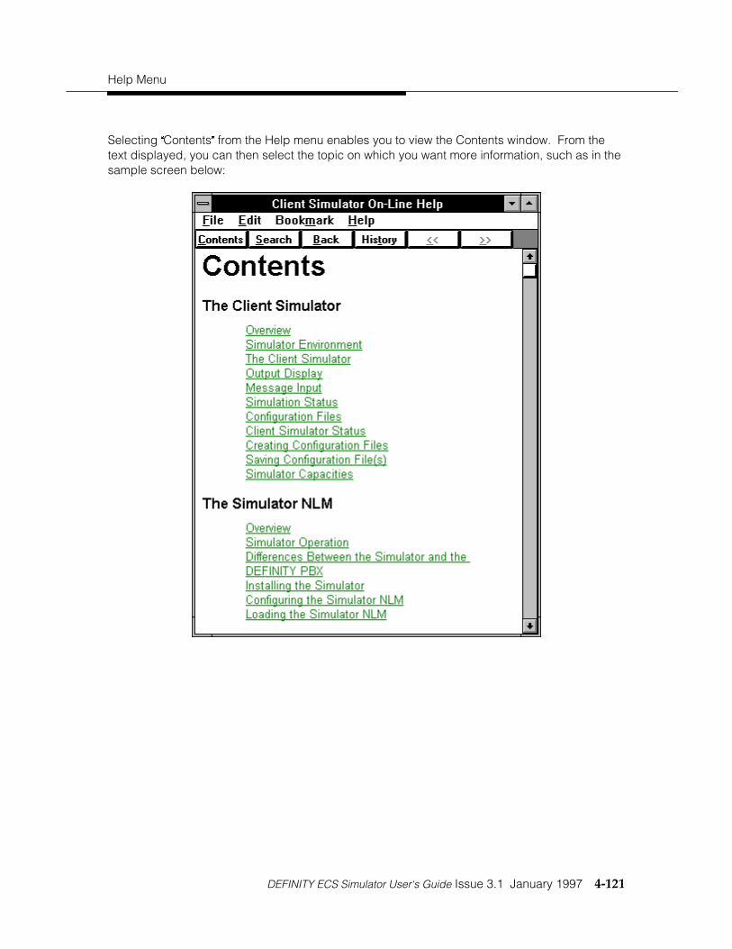
Help Menu
DEFINITY ECS Simulator User‘s Guide Issue 3.1 January 1997 4-121
Selecting ÕContentsÖ from the Help menu enables you to view the Contents window. From thetext displayed, you can then select the topic on which you want more information, such as in thesample screen below:


DEFINITY ECS Simulator User‘s Guide Issue 3.1 January 1997 I-1
Index
AACDs, 3-19Admin Menu, 3-3Administration Menu, 3-3Alternate Call, 4-3Answer Call, 4-5Application
testing, 2-3Automatic Response to Route Requests, 4-69Automatic Routing Feature, 4-69Away Worktop (Device list), 4-51
CCall Completion, 4-6Call Control (Device list), 4-51Call Control Services, 4-2Call/Call Monitor (Device list), 4-51Call/Device Monitor (Device list), 4-51Change Device Parameters, 4-111Change Monitor Filter, 4-94Change System Status Filter, 4-40Clear Call, 4-7Clear Connection, 4-8Client Simulator, 1-3Client Simulator Session
closing, 2-7Client Simulator Status, 1-5CLSIM.EXE, 1-6, 2-2Conference Call, 4-11Configuration Files, 1-4
saving, 3-23Console interface, prerequisites, 2-11Consultation Call, 4-13
DDeflect Call, 4-16Device ID Type, 4-9Device list, 4-51Device Parameters, 4-111Device/Device Monitor (Device list), 4-51Disable Link, 4-108Dynamic events, 4-102
E
Enable Link, 4-109Enabling Tracing, 4-119End Route, 4-107Escape Service, 4-35Escape Service Confirmation, 4-37Escape Services, 4-34Escape Services supported by Simulator, 4-34Exerciser Session at Client Simulator, 2-5
FFile Menu, 3-2Filter Selection, 4-100Filtering button, 4-100Finish Monitor, 4-106First Digit Table, 3-6Functions
Call Control Services, 4-2Escape Services, 4-34Maintenance Services, 4-39Query Services, 4-48Routing Services, 4-67Set Feature Services, 4-83Snapshot Services, 4-90Status Reporting Services, 4-93
GG3PD Private Data, 4-9G3PD Private Filter button, 4-100Get API Capabilities, 4-49Get Device List, 4-50Group Pickup Call, 4-17
HHelp Menu, 4-120, 4-121Hold Call, 4-18Home Worktop (Device list), 4-51
IIn-bound Calls, 4-105Index field, defined, 4-50Installation Prerequisites, 2-1Installed Application Environment, 1-2

I-2 January 1997 Issue 3.1 DEFINITY ECS Simulator User‘s Guide
MMaintenance Services, 4-39Make Call, 4-19Make Call request, 1-2Make Predictive Call, 4-22Manual Digit Collection, 3-5Manual Operations
simulating, 2-8Manual Routing, 4-74Manual Routing Dialog, 4-74Message Input, 1-4Message Tracing Via Client SimulatorInterface, 2-7Monitor Call, 4-95Monitor Calls Via Device, 4-96Monitor Device, 4-97Monitor Stop, 4-98Monitor Stop on Call, 4-99MS Windows, 2-1
OOCI Tab, 2-23Off-hook, 4-103On-hook, 4-104Output Display, 1-4
PParameters, 4-111PBX Driver, 1-1PBX Menu, 4-102Pickup Call, 4-25Primary event rejection, 4-38Private Data (DEFINITY), 4-35Private Data (non-DEFINITY), 4-35Private Data button, 4-9
QQuery ACD Split, 4-60Query Agent Login, 4-61Query Agent State, 4-53Query All ACD Groups, 4-117Query All Active Calls, 4-114Query All Monitors, 4-118Query All Stations, 4-115Query All Trunk Groups, 4-116Query Call, 4-113Query Call Classifier, 4-62Query Call Monitor, 4-52Query Device, 4-112
Query Device Information, 4-55Query Device Name, 4-63Query Do Not Disturb, 4-56Query Forwarding, 4-57Query Last Number, 4-58Query Message Waiting Indicator, 4-59Query Services, 4-48Query Station Status, 4-64Query Time of Day, 4-65Query Trunk Group, 4-66
RReconnect Call, 4-26Retrieve Call, 4-29Route End, 4-76Route Register, 4-78Route Register Cancel, 4-77Route Select, 4-79Route System Parameters, 4-68Route Tables, 4-69Route Tables (Automatic Routing Feature),4-69Routing (Device list), 4-51Routing Services, 4-67Routing Tab, 2-19Routing, automatic, 4-69Routing, manual, 4-74
SSend DTMF Tone, 4-32Send Private Event, 4-38Set Agent State, 4-84Set Do Not Disturb, 4-86Set Feature Services, 4-83Set Forwarding, 4-87Set Message Waiting Indicator, 4-89SIM.DLL, 2-1simcons.exe, 1-3, 1-6, 1-7, 2-11Simulation Status, 1-4Simulator
capabilities and limitations, 1-1configuring, 2-2definition, 1-1differences from DEFINITY PBX, 1-8environment, 1-3installing, 2-1loading, 2-2operation, 1-7
Simulator Capacities, 3-23

DEFINITY ECS Simulator User‘s Guide Issue 3.1 January 1997 I-3
Simulator Console Interface, 1-6, 2-11Simulator DLL, 1-6Simulator Menu, 4-110Simulator operation
global parameters, 3-4Simulator Session at Client Simulator
establishing, 2-3Simulator Test Environment, 1-2Snapshot Call, 4-91Snapshot Device, 4-92Software Developer Kit, 2-1Stations, 3-8System Parameters, 3-4System Status Event Send, 4-45System Status Filtering, 4-47System Status Request, 4-41System Status Request Confirmation, 4-46System Status Start, 4-42System Status Stop, 4-44
TTesting applications, 2-3Tracing, Disabling/Enabling, 4-119Transfer Call, 4-30Trunk Groups, 3-16
UUEC Tab, 2-20Unsupported features, 1-10User to User Information, 4-10Using the Simulator Console Interface, 2-11UUI, 4-10UUI Tab, 2-17Windows NT server, 1-3, 1-6, 2-1


