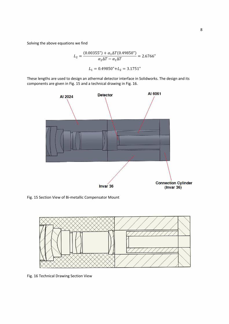
1 Passive Athermalization of an Infrared Optical System OPTI 521 Tutorial Report James Champagne Introduction This tutorial will cover the design of an athermal lens mount for an infrared double-Gauss objective. This objective will need to be able to survive a space environment. It will experience large temperature changes and needs to remain in focus so imaging can occur continuously. The lens will image the earth through wavelengths of 3-5 microns. Normal optical glass does not transmit in this range so infrared glasses were used in the optical design. Infrared glasses tend to have high changes in refractive index under temperature changes and thus tend to cause defocus in infrared optical systems. ZEMAX will be used to determine the change in focus through the expected temperature changes in Earth orbit. A lens mount composed of materials of differing coefficients of thermal expansion will then be designed to compensate the change in focus at the detector plane. Optical Design The optical design of this system was performed in ZEMAX. It is a double-Gauss type objective designed to image over wavelengths 3-5 microns. The lens has a total of 6 lens elements with 5 different glass types. The design also consists of two doublets that will be cemented together. The design covers a full field of view of 20 degrees and will cover a sensor with a 1 inch diagonal (0.707” x 0.707”). With an F/# of 3, the entrance pupil diameter is 1 inch and the effective focal length is 3 inches. This design can easily fit within a cube satellite that has dimensions 10 cm x 10 cm x 10 cm (4” x 4” x 4”). The lens prescription, optical layout, and performance data are given below. Fig. 1 Lens Prescription (units: inches) Fig. 2 Optical Layout
Transcript
1
Passive Athermalization of an Infrared Optical System
OPTI 521 Tutorial Report
James Champagne
Introduction
This tutorial will cover the design of an athermal lens mount for an infrared double-Gauss objective. This
objective will need to be able to survive a space environment. It will experience large temperature
changes and needs to remain in focus so imaging can occur continuously. The lens will image the earth
through wavelengths of 3-5 microns. Normal optical glass does not transmit in this range so infrared
glasses were used in the optical design. Infrared glasses tend to have high changes in refractive index
under temperature changes and thus tend to cause defocus in infrared optical systems. ZEMAX will be
used to determine the change in focus through the expected temperature changes in Earth orbit. A lens
mount composed of materials of differing coefficients of thermal expansion will then be designed to
compensate the change in focus at the detector plane.
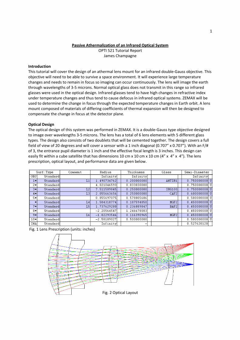
Optical Design
The optical design of this system was performed in ZEMAX. It is a double-Gauss type objective designed
to image over wavelengths 3-5 microns. The lens has a total of 6 lens elements with 5 different glass
types. The design also consists of two doublets that will be cemented together. The design covers a full
field of view of 20 degrees and will cover a sensor with a 1 inch diagonal (0.707” x 0.707”). With an F/#
of 3, the entrance pupil diameter is 1 inch and the effective focal length is 3 inches. This design can
easily fit within a cube satellite that has dimensions 10 cm x 10 cm x 10 cm (4” x 4” x 4”). The lens
prescription, optical layout, and performance data are given below.
Fig. 1 Lens Prescription (units: inches)
Fig. 2 Optical Layout
2
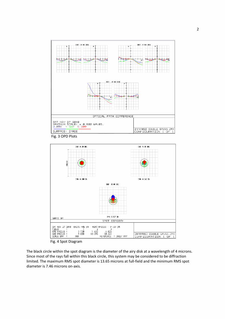
Fig. 3 OPD Plots
Fig. 4 Spot Diagram
The black circle within the spot diagram is the diameter of the airy disk at a wavelength of 4 microns.
Since most of the rays fall within this black circle, this system may be considered to be diffraction
limited. The maximum RMS spot diameter is 13.65 microns at full-field and the minimum RMS spot
diameter is 7.46 microns on-axis.
3
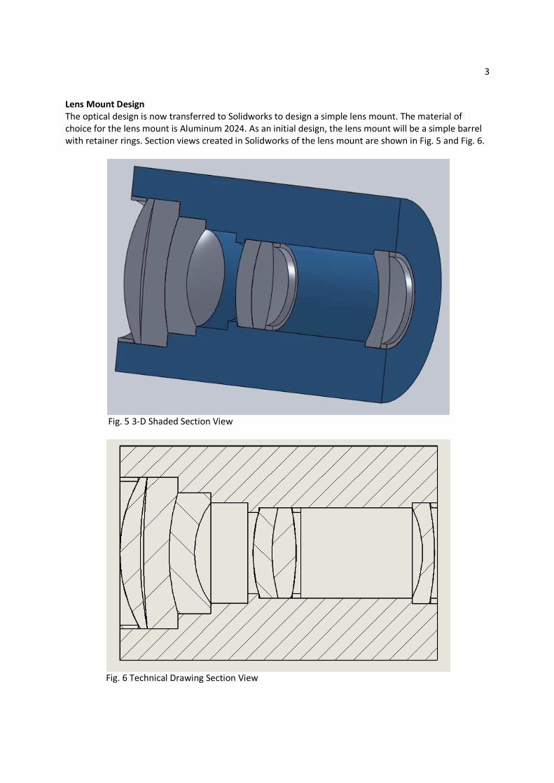
Lens Mount Design
The optical design is now transferred to Solidworks to design a simple lens mount. The material of
choice for the lens mount is Aluminum 2024. As an initial design, the lens mount will be a simple barrel
with retainer rings. Section views created in Solidworks of the lens mount are shown in Fig. 5 and Fig. 6.
Fig. 5 3-D Shaded Section View
Fig. 6 Technical Drawing Section View
4
Thermal Analysis
A thermal analysis is performed in ZEMAX to determine the amount of defocus that will occur in a space
environment. A few settings within ZEMAX need to be changed in order to make use of its thermal
analysis features. First allow ZEMAX to adjust index data to the specified environment. This setting is
under the general tab and is shown in Fig. 7. We will assume that the objective has a fixed focus
optimized for a temperature of 0 ℃ and a pressure of 0 ATM.
Fig. 7 General Tab/ Environment
After this change, the performance of the objective degraded slightly due to the change in pressure and
temperature. The back focal length is then re-optimized to achieve a minimum RMS spot size. The BFL
changes from 0.5000” to 0.4985”. This provides the smallest RMS spot size at 0 ℃ and 0 ATM.
To simulate the expansion of the lens mount, the CTE’s of the airspaces between the lens elements are
set to be equal to the CTE of aluminum 2024 (� = 22.9 �� ℃⁄ ). This data is entered into the Lens
Data Editor on the far right side for the two large air spaces of the objective as shown in Fig. 8. The lens
mount stops at the last element in this design so the CTE is left to be zero for the BFL airspace. A better
approximation for the expansion of the lens mount would take into account the lens mount material
around each lens element.
Fig. 8 Coefficient of thermal expansion of lens mount (Al 2024) in lens data editor
5
Large temperature changes will be expected for a space environment due to the objective entering and
exiting the earth’s shadow. The equilibrium temperature of the imaging satellite will be a function of its
thermal emissivity, radiation absorbtivity, and how much of the satellite is exposed to radiation. For our
model, we will assume temperatures range from 0℃ to 60℃.
The Multi-Configuration Editor within ZEMAX can be used to model the lens and mount over a
temperature range. Thermal analysis is performed by choosing “Make Thermal” under the tools menu in
the Multi-Configuration Editor as can be seen in Fig. 9.
Fig. 9 Make Thermal
The Make Thermal Setup is filled out as shown in Fig. 10.
Fig. 10 Thermal Setup
ZEMAX produces 10 configurations ranging from 0℃ to 60℃. Cycling through each configuration, it is
possible to view the change in performance of the objective. Choose configuration 11 with a
temperature of 60℃ (Fig.11) and notice how all parameters change in the Lens Data Editor. Analysis of
this configuration is performed by choosing “Make Single Config.” under the Tools Menu in the Multi-
Configuration Editor. All parameters in the Lens Data Editor are now fixed.
6
Fig. 11 Configuration 11 with 60℃ temperature change
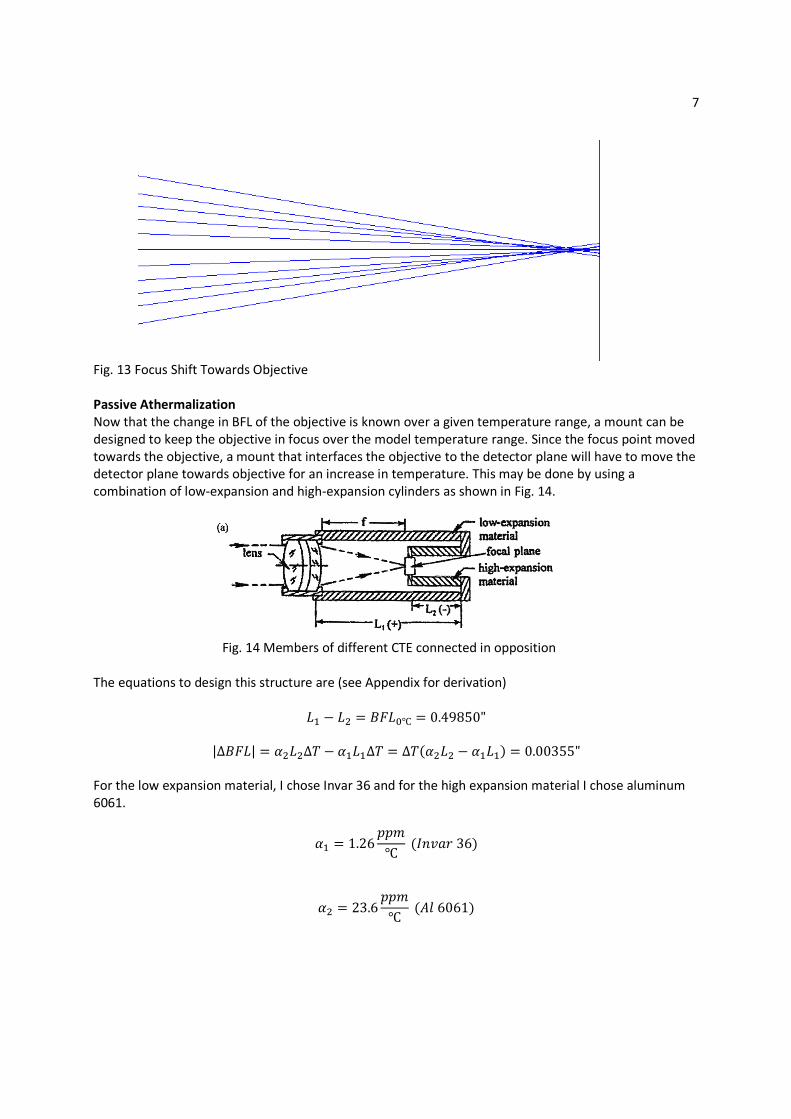
For this change in temperature of 60℃, the new spot diagram can be seen in Fig. 12. The objective is
now slightly out of focus. The direction of focus shift can be seen from the rays intersecting the image
plane in Fig. 13. As can be seen, the focus has shifted towards the objective. The amount of defocus can
be measured by re-optimizing the back focal length to obtain a minimum RMS spot size. The change in