International Forum on Aeroelasticity and Structural Dynamics IFASD 2017 25-28 June 2017 Como, Italy PASSIVE GUST LOADS ALLEVIATION IN A TRUSS-BRACED WING USING INTEGRATED DAMPERS Christopher P. Szczyglowski 1 , Simon A. Neild 1 , Brano Titurus 1 , Jason Z. Jiang 1 , Jonathan E. Cooper 1 , Etienne Coetzee 2 1 Faculty of Engineering University of Bristol Bristol, BS8 1TR, United Kingdom [email protected]2 Airbus Filton, Bristol, BS34 7PA, United Kingdom Keywords: truss-braced wing, discrete gust, loads alleviation, passive, dampers. Abstract: Gust load cases tend to be critical for sizing the wing components and therefore methods of gust loads alleviation are necessary in order to reduce the overall weight of the wing structure. In this paper a method of gust loads alleviation for a truss-braced wing will be intro- duced which uses linear, rotational, viscous dampers co-located at the hinge joints connecting the truss structure to the wing to provide damping and thereby loads relief to the stress levels during a ”1-cosine” gust. The aeroelastic model is based on the NASA/Boeing SUGAR VOLT truss-braced wing and MSC.Nastran is used throughout the study to compute the gust response. It is found that large values of torsional viscous damping coefficient are required in order to provide moderate loads relief across the wing. Furthermore, it is found that a damper placed at the strut-fuselage joint is more beneficial than a damper located at the strut-wing joint due to its consistent performance across a range of gusts. 1 INTRODUCTION There has been much research in recent years in the use of more energy efficient aircraft con- figurations that will meet the environmental performance requirements required by initiatives such as Vision 2020 and Flight Path 2050. One solution is the implementation of new aircraft concepts that can provide a step change in performance over the current commercial airliner design. One such concept is the Truss-Braced Wing (TBW) aircraft; originally championed by Hurel Dubois during the 1940s [1] it has since become the subject of a major study conducted by NASA and Boeing under the name Subsonic Ultra Green Aircraft Research (SUGAR) [2]. A strut-braced wing provides many benefits over a traditional cantilever design. Firstly, the loads alleviation provided by the strut means that the inboard wing section can have a reduced chord and thickness compared to an equivalent cantilever wing. The strut also allows a larger wingspan to be achieved which, when combined with the reduced chord, results in an increased aspect ratio providing an overall aerodynamic benefit, however, the interference drag associated with the truss structure can have a detrimental effect on performance if it is not properly de- signed. Despite this, numerous studies have shown, combining all of these effects can provide a significant reduction on take-off weight and fuel burn [3–9]. 1
Transcript
International Forum on Aeroelasticity and Structural DynamicsIFASD 2017
25-28 June 2017 Como, Italy
PASSIVE GUST LOADS ALLEVIATION IN A TRUSS-BRACED WINGUSING INTEGRATED DAMPERS
Christopher P. Szczyglowski1, Simon A. Neild1, Brano Titurus1, Jason Z. Jiang1,Jonathan E. Cooper1, Etienne Coetzee2
Abstract: Gust load cases tend to be critical for sizing the wing components and thereforemethods of gust loads alleviation are necessary in order to reduce the overall weight of the wingstructure. In this paper a method of gust loads alleviation for a truss-braced wing will be intro-duced which uses linear, rotational, viscous dampers co-located at the hinge joints connectingthe truss structure to the wing to provide damping and thereby loads relief to the stress levelsduring a ”1-cosine” gust. The aeroelastic model is based on the NASA/Boeing SUGAR VOLTtruss-braced wing and MSC.Nastran is used throughout the study to compute the gust response.It is found that large values of torsional viscous damping coefficient are required in order toprovide moderate loads relief across the wing. Furthermore, it is found that a damper placed atthe strut-fuselage joint is more beneficial than a damper located at the strut-wing joint due to itsconsistent performance across a range of gusts.
1 INTRODUCTION
There has been much research in recent years in the use of more energy efficient aircraft con-figurations that will meet the environmental performance requirements required by initiativessuch as Vision 2020 and Flight Path 2050. One solution is the implementation of new aircraftconcepts that can provide a step change in performance over the current commercial airlinerdesign. One such concept is the Truss-Braced Wing (TBW) aircraft; originally championed byHurel Dubois during the 1940s [1] it has since become the subject of a major study conductedby NASA and Boeing under the name Subsonic Ultra Green Aircraft Research (SUGAR) [2].
A strut-braced wing provides many benefits over a traditional cantilever design. Firstly, theloads alleviation provided by the strut means that the inboard wing section can have a reducedchord and thickness compared to an equivalent cantilever wing. The strut also allows a largerwingspan to be achieved which, when combined with the reduced chord, results in an increasedaspect ratio providing an overall aerodynamic benefit, however, the interference drag associatedwith the truss structure can have a detrimental effect on performance if it is not properly de-signed. Despite this, numerous studies have shown, combining all of these effects can providea significant reduction on take-off weight and fuel burn [3–9].
1
IFASD-2017-190
Preliminary sizing analysis carried out as part of the SUGAR project [9,10] has shown that gustloads and other aeroelastic phenomena such as flutter are the main design drivers which size thestructural components in a truss-braced wing. Traditionally, reducing gust loads or increasingthe flutter speed would require specific tailoring of the stiffness and/or mass properties of thestructure, which would lead to an inevitable increase in mass.
An alternative strategy is to operate aerodynamic control surfaces using control laws in order tomodify the wing aerodynamic forces in such a way that the wing gust response is alleviated [11].This method is now commonplace within the aerospace industry and many commerical aircraftoperate this system. An extension to this method which has received an increased level of re-search in recent years is the use of the wing tip to provide loads alleviation. Castrichini etal. [12] investigated a folding wing tip device which could reduce static and dynamic loads bycareful design on the hinge stiffness and hinge angle. Similarly, a Variable Geometry RakedWing Tip [13] has been proposed as part of the SUGAR project which utilises the sweep of thewing tip device to provide a restoring torque to the wing in order to counteract aerodynamic mo-ments and provide roll control. This device has also been incorporated into a multi-disciplinaryoptimisation scheme by Mallik et al. [14] and it was found that such a device allowed the oper-ation of TBW configurations that otherwise would have failed the flutter constraints.
In this paper a novel approach to gust loads alleviation is proposed which utilises a damperintegrated into the truss structure to provide additional damping and thereby loads relief duringdynamic responses. The truss introduces several joint locations where a two-terminal devicesuch as a damper, a spring-damper or even a more elaborate device such as a tuned-inerter-damper [15] could be utilised to reduce dynamic loads or alleviate flutter. This study willinvestigate the ability of a rotational viscous damper located at one of the truss hinge joints toreduce the maximum sectional stresses throughout a discrete ”1-cosine” gust. A damper deviceis considered to be the simplest possible dynamic device and will act as a suitable baseline forany further studies.
This paper begins with a description of the aeroelastic model and the method for modelling thedampers, as well as an explanation for the different joint connections and boundary conditionsused throughout the analysis, this is carried out using MSC.Nastran [16]. Next, the normalmodes of the TBW model are determined before performing a gust analysis on the TBW modelin the clean configuration (i.e. without any dampers). Once the baseline gust response of themodel has been determined the gust response is found for two different damper locations and avariety of damping coefficients. Finally, the findings of the study are discussed and conclusionsare drawn in the final section as well as suggestions for further work.
2 TRUSS-BRACED WING AEROELASTIC MODEL
2.1 Structural Modelling
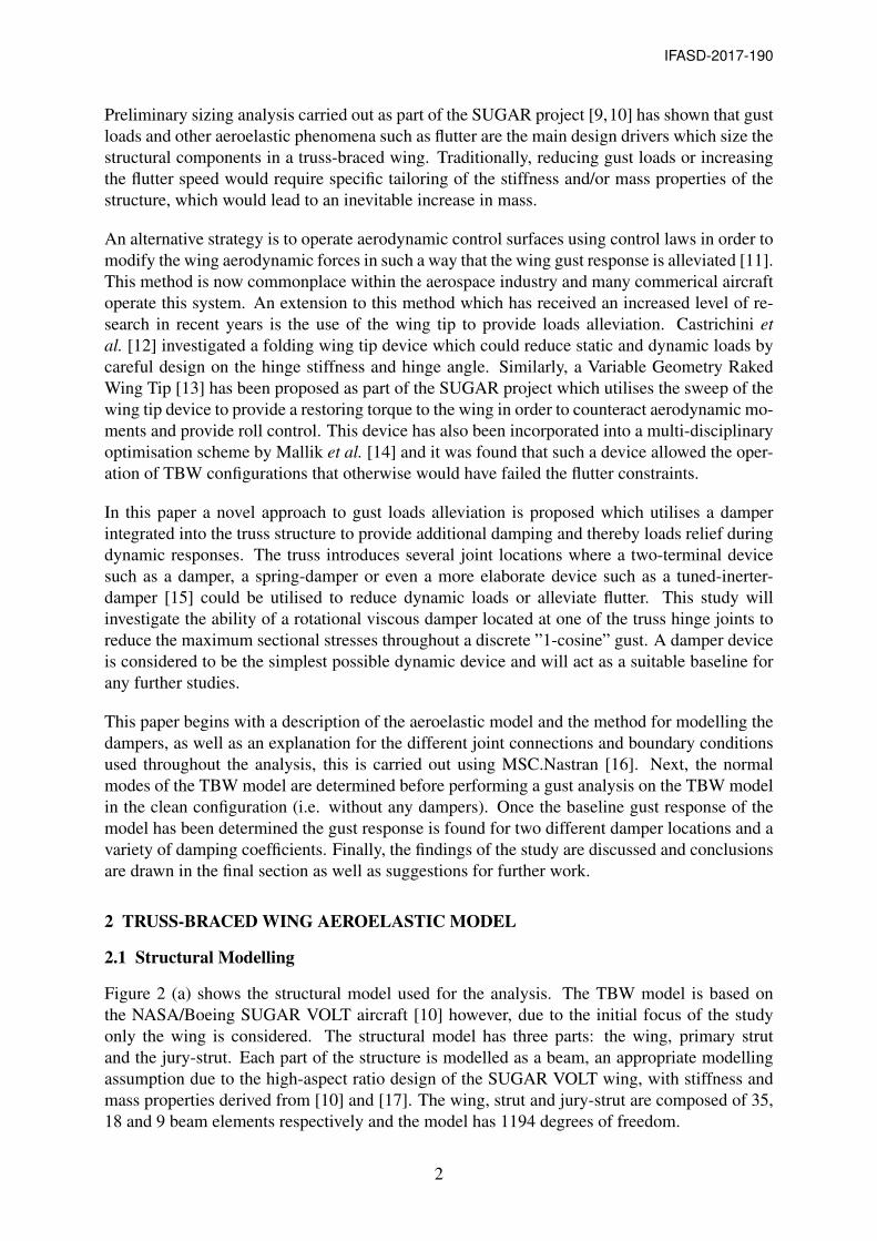
Figure 2 (a) shows the structural model used for the analysis. The TBW model is based onthe NASA/Boeing SUGAR VOLT aircraft [10] however, due to the initial focus of the studyonly the wing is considered. The structural model has three parts: the wing, primary strutand the jury-strut. Each part of the structure is modelled as a beam, an appropriate modellingassumption due to the high-aspect ratio design of the SUGAR VOLT wing, with stiffness andmass properties derived from [10] and [17]. The wing, strut and jury-strut are composed of 35,18 and 9 beam elements respectively and the model has 1194 degrees of freedom.
2
IFASD-2017-190
Y0
zwing
ywing
xwing
zstrut y
strut
xstrut
zjury
xjury
yjury
Z0
X0
Wing Reference Node(Fully Fixed)
Strut-wing offsetRigid Connections
Strut
Wing
Jury-Strut
Flow in positive X0 direction
Hinge JointsDependant DOFs : x, y, z, θ
y, θ
z
Figure 1: Schematic of the TBW model.
The topology of the truss-structure matches the SUGAR VOLT wing and is defined using thedata in Figures 3.1-3.3 of [10]. The strut attaches to the wing at approximately 58% wing semi-span and is offset from the beam-line towards the leading edge in order to provide a passiveloads alleviation benefit [8]. The jury-strut root position is at the mid-point of the primary strutand extends vertically upwards, meeting the wing at 35% of the wing semi-span.
For this study it is assumed that the truss-structure is connected to the wing via simple hingejoints. These joints allow rotation about the local beam x-axis whilst all other Degrees Of Free-dom (DOF) are dependant. This means that out-of-plane bending moments are not transferredacross these joints however, all forces as well as in-plane and torque moments are transmitted.Figure 1 describes the model orientation and the dependent DOF at each connection point. Thewing model is fully-fixed at the wing reference node and additional boundary conditions areenforced at the wing root, wing kink and the strut-root via the use of RBE2 elements. Thewing reference node lies on the centre line of the fuselage and is aligned with the Nastran basiccoordinate system.
2.2 Aerodynamic Modelling
Figure 2 (b) shows the aerodynamic mesh for the TBW. The aerodynamic forces and momentsare calculated using the Double Lattice Method (DLM) provided as part of the aeroelastic so-lution sequences in MSC.Nastran. The doublet lattice method is based on linear unsteady po-tential flow theory, meaning that the aerodynamic forces are only valid for inviscid, irrotational,incompressible and attached flow, subject to small angles of attack or side-slip. Despite theselimitations the DLM aerodynamics are considered to be appropriate in order to obtain an un-derstanding of the general wing response to a discrete gust.
For this study the aerodynamic coordinate system is aligned with the basic coordinate system(X0, Y0, Z0) and the wing and the primary strut are modelled as aerodynamic surfaces, in keep-ing with the assumptions of the SUGAR VOLT wing model. As the model comprises only thehalf-wing a symmetry condition is applied in the X-Z plane in order to obtain the correct span-wise distribution of the aerodynamic forces. A surface spline is used to connect the aerodynamicmesh to the structural grid nodes and transfer all forces and displacements. The aerodynamicmesh comprises 1010 aerodynamic panels with 900 in the wing 110 in the primary strut. Eachpanel is approximately 0.25m wide (Y0 direction) and 0.32m long (X0 direction).
One deviation from the SUGAR VOLT model is that for this study the primary-strut has a
3
IFASD-2017-190
(a) Structural model (b) Aerodynamic model
Figure 2: Truss-braced wing structural and aerodynamic model.
constant chord length, as opposed to the distinctive bow-tie shape of the SUGAR VOLT primarystrut, this is done in order to maintain the simplicity of the model. The chord value for theprimary strut is based on the average of the SUGAR VOLT values.
2.3 Damper Modelling
To maintain simplicity the dampers are modelled as simple dashpot dampers generating linear,viscous damping. The dampers are rotational devices meaning that they provide a momentproportional to the relative angular velocity of the two terminals of the device.
Mdamper = c(θ̇A − θ̇B
)(1)
where θ̇A is the angular velocity at the master node, θ̇B is the angular velocity at the slavenode, c is the torsional viscous damping coefficient and Mdamper is the moment generated bythe damper. The dampers are included in the structural model as CBUSH elements [18].
3 EIGENANALYSIS
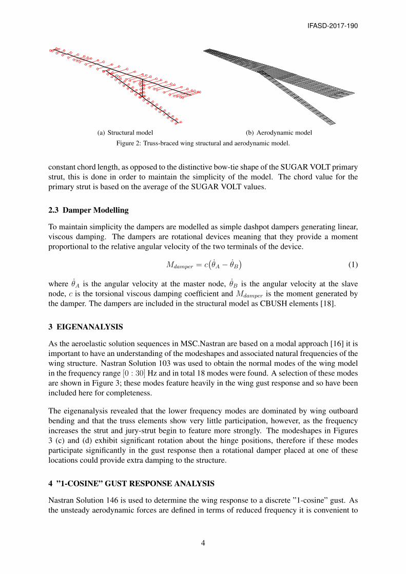
As the aeroelastic solution sequences in MSC.Nastran are based on a modal approach [16] it isimportant to have an understanding of the modeshapes and associated natural frequencies of thewing structure. Nastran Solution 103 was used to obtain the normal modes of the wing modelin the frequency range [0 : 30] Hz and in total 18 modes were found. A selection of these modesare shown in Figure 3; these modes feature heavily in the wing gust response and so have beenincluded here for completeness.
The eigenanalysis revealed that the lower frequency modes are dominated by wing outboardbending and that the truss elements show very little participation, however, as the frequencyincreases the strut and jury-strut begin to feature more strongly. The modeshapes in Figures3 (c) and (d) exhibit significant rotation about the hinge positions, therefore if these modesparticipate significantly in the gust response then a rotational damper placed at one of theselocations could provide extra damping to the structure.
4 ”1-COSINE” GUST RESPONSE ANALYSIS
Nastran Solution 146 is used to determine the wing response to a discrete ”1-cosine” gust. Asthe unsteady aerodynamic forces are defined in terms of reduced frequency it is convenient to
4
IFASD-2017-190
Z [m
]
-4
-2
0
Y [m]0 5 10 15 20 25
(a) First wing bending mode at 1.83Hz (Mode 1).
Z [m
]
-4
-2
0
Y [m]0 5 10 15 20 25
(b) Global bending mode at 2.83Hz (Mode 3).
Z [m
]
-4
-2
0
Y [m]0 5 10 15 20 25
(c) Jury-strut bending mode at 8.03Hz (Mode 6).
Z [m
]
-4
-2
0
Y [m]0 5 10 15 20 25
(d) Strut bending mode at 9.72Hz (Mode 8).
Figure 3: Truss-braced wing modeshapes. Black denotes the deflected shape of the beam elements and red is theoutline of the TBW planfrom for this deflected shape.
compute the response in the frequency domain using modal coordinates. The generic aeroelasticequation of motion for dynamic aerolasticty in [16] is given by[
−Mhhω2 + iBhhω + (1 + ig)Khh −
1
2V 2Qhh(m, k)
]{qh} = {P (ω)} (2)
where ω is the excitation frequency, Mhh is the modal mass matrix, Bhh is the modal dampingmatrix, g is the structural damping parameter,Khh is the modal stiffness matrix, V is the aircraftforward velocity and Qhh is the matrix of aerodynamic forces which is a function of reduced
5
IFASD-2017-190
frequency (k) and Mach number (m), qh are the modal coordinates and P (ω) is the applied loaddefined as a function of excitation frequency.
The terms on the left-hand side of Equation 2 are determined automatically by MSC.Nastranbased on the model definition and aircraft velocity for a set of user-defined values of reducedfrequency and Mach number. The inclusion of a gust in Equation 2 requires the frequency varia-tion of the gust to be specified, however, as the certification requirements define the gust profilein the time domain [19] it is more convenient to first define the gust as a time varying signaland then transform this into the frequency domain using the Fourier Transform. This process isentirely automated within MSC.Nastran and does not require any additional computation oncethe time domain gust signal has been defined.
Using the ”1-cosine” definition of a discrete gust yields
wg(t) =Uds
2
[1− cos(πV t
H)], (3)
which is taken directly from the certification requirements for large aircraft, Certification Spec-ification 25 (CS-25), as provided by EASA [19]. Here wg is the gust vertical velocity, H isthe gust gradient (distance to reach the peak gust velocity), V is the aircraft forward velocity inTAS and Uds is the gust design velocity, defined as
Uds = UrefFg
( H
106.17
) 16 , (4)
where Fg is the flight load alleviation factor and Uref is the reference gust velocity in EAS,varied linearly from 13.4m/s EAS at 15,000ft to 7.9m/s EAS at 50,000ft as specified in CS-25.Assuming that the aircraft is operating at a cruise altitude and Mach number of 36,000ft andM=0.75 respectively [10], yielding a gust reference velocity of 10.12m/s EAS and a flight loadalleviation factor 0.98. Furthermore, a frequency resolution of ∆f = 0.005Hz is selected and6000 frequency increments are defined in order to cover the frequency range [0 : 30] Hz.
Finally, it is important to note that as the wing reference node is fully-fixed, the rigid bodymodes will not participate in the gust response. This will of course have a significant effecton the participation of the flexible modes, however, as this is a preliminary investigation thissimple approach is deemed satisfactory.
5 GUST RESPONSE OF THE TRUSS-BRACED WING
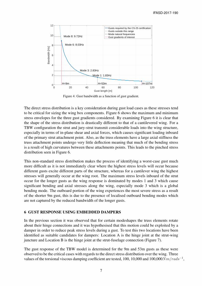
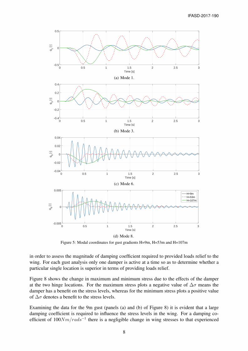
Before the loads alleviation of the damper can be assessed the baseline gust response of theTBW must be established. Three gust gradients are considered, 9m, 53m and 107m, in order tounderstand the effect that the different frequency content of these gusts will have on the modalresponse of the wing (Figure 4).
From Figure 5 it is clear that the wing response across all of the gusts is dominated by modes1 and 3. This is because the natural frequencies of these modes are within the frequency band-width of each of the gusts and will therefore feature strongly. However, it is interesting to notethat modes 6 and 8, which are jury-strut/strut dominated, do not feature significantly in the 53mand 107m gusts as these higher frequency modes fall outside the bandwidth of the longer gusts.For the shorter gusts the frequency bandwidth is much higher and therefore a larger number ofmodes feature in the response, this will lead to additional parts of the structure being excitedwhich will have a knock-on effect on the stresses throughout the wing.
6
IFASD-2017-190
Gust length [m]0 20 40 60 80 100 120
Ban
dwid
th [H
z]
0
2
4
6
8
10
12
Mode 1: 1.83Hz
Mode 3: 2.83Hz
Mode 6: 8.03Hz
Mode 8: 9.72Hz
H=9m H=53m H=107m
Gusts required by the CS-25 certificationGusts outside this rangeMode natural frequenciesGust gradients of interest
Figure 4: Gust bandwidth as a function of gust gradient.
The direct stress distribution is a key consideration during gust load cases as these stresses tendto be critical for sizing the wing box components. Figure 6 shows the maximum and minimumstress envelopes for the three gust gradients considered. By examining Figure 6 it is clear thatthe shape of the stress distribution is drastically different to that of a cantilevered wing. For aTBW configuration the strut and jury-strut transmit considerable loads into the wing structure,especially in terms of in-plane shear and axial forces, which causes significant loading inboardof the primary strut attachment point. Also, as the truss elements have a large axial stiffness thetruss attachment points undergo very little deflection meaning that much of the bending stressis a result of high curvatures between these attachments points. This leads to the pinched stressdistribution seen in Figure 6.
This non-standard stress distribution makes the process of identifying a worst-case gust muchmore difficult as it is not immediately clear where the highest stress levels will occur becausedifferent gusts excite different parts of the structure, whereas for a cantilever wing the higheststresses will generally occur at the wing root. The maximum stress levels inboard of the strutoccur for the longer gusts as the wing response is dominated by modes 1 and 3 which causesignificant bending and axial stresses along the wing, especially mode 3 which is a globalbending mode. The outboard portion of the wing experiences the most severe stress as a resultof the shorter 9m gust, this is due to the presence of localised outboard bending modes whichare not captured by the reduced bandwidth of the longer gusts.
6 GUST RESPONSE USING EMBEDDED DAMPERS
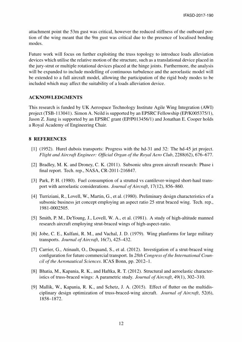
In the previous section it was observed that for certain modeshapes the truss elements rotateabout their hinge connections and it was hypothesised that this motion could be exploited by adamper in order to reduce peak stress levels during a gust. To test this two locations have beenidentified as suitable candidates for dampers: Location A is the hinge joint at the strut-wingjuncture and Location B is the hinge joint at the strut-fuselage connection (Figure 7).
The gust response of the TBW model is determined for the 9m and 53m gusts as these wereobserved to be the critical cases with regards to the direct stress distribution over the wing. Threevalues of the torsional viscous damping coefficient are tested, 100, 10,000 and 100,000Nm/rads−1,
7
IFASD-2017-190
Time [s]0 0.5 1 1.5 2 2.5 3
q1 [-
]
-0.5
0
0.5
(a) Mode 1.
Time [s]0 0.5 1 1.5 2 2.5 3
q3 [-
]
-0.4
-0.2
0
0.2
0.4
(b) Mode 3.
Time [s]0 0.5 1 1.5 2 2.5 3
q6 [-
]
-0.04
-0.02
0
0.02
0.04
(c) Mode 6.
Time [s]0 0.5 1 1.5 2 2.5 3
q8 [-
]
-0.005
0
0.005H=9mH=53mH=107m
(d) Mode 8.
Figure 5: Modal coordinates for gust gradients H=9m, H=53m and H=107m
in order to assess the magnitude of damping coefficient required to provided loads relief to thewing. For each gust analysis only one damper is active at a time so as to determine whether aparticular single location is superior in terms of providing loads relief.
Figure 8 shows the change in maximum and minimum stress due to the effects of the damperat the two hinge locations. For the maximum stress plots a negative value of ∆σ means thedamper has a benefit on the stress levels, whereas for the minimum stress plots a positive valueof ∆σ denotes a benefit to the stress levels.
Examining the data for the 9m gust (panels (a) and (b) of Figure 8) it is evident that a largedamping coefficient is required to influence the stress levels in the wing. For a damping co-efficient of 100Nm/rads−1 there is a negligible change in wing stresses to that experienced
Figure 6: Wing direct stress envelope for gust gradients H=9m, H=53m and H=107m.
when no damper is fitted. Increasing c to 10,000Nm/rads−1 provides a peak reduction of5× 106N/m2 at approximately 85% of the semi-span using a device at Location B and increas-ing c further to 100,000Nm/rads−1 yields a three fold reduction in stress of 15× 106N/m2 atthe same spanwise location.
The 9m gust results show that a damper at either location is capable of providing some loadsrelief to the wing, with the damper at Location B providing a larger reduction in stress for agiven value of damping coefficient for the majority of locations, the exception being at the wingroot position where the strut-wing joint damper is superior. However, a damper placed at thestrut-wing joint can cause an increase in the absolute values of stress along the wing which isclearly not desirable. This is also the case for the strut-fuselage damper, however the effect ismuch reduced. In general, a large damping coefficient yields a larger reduction in stress levels,however, as previously mentioned this can lead to an increase in stress for some parts of thewing for a device at Location A.
The reduction in minimum stress levels for the 9m gust follows the same broad trends as themaximum stresses: the strut-fuselage damper has the best performance across the span with theexception of the wing root stresses where the strut-wing dampers provides a better reduction
Figure 7: Side view of the TBW with the damper positions annotated.
9
IFASD-2017-190
Non-dimensional span [-]0 0.2 0.4 0.6 0.8 1
"<
[N/m
2]
#107
-2
-1.5
-1
-0.5
0
0.5
1
1.5
2
(a) Maximum stress, H=9m.
Non-dimensional span [-]0 0.2 0.4 0.6 0.8 1
"<
[N/m
2]
#107
-2
-1.5
-1
-0.5
0
0.5
1
1.5
2
(b) Minimum stress, H=9m.
Non-dimensional span [-]0 0.2 0.4 0.6 0.8 1
"<
[N/m
2]
#107
-1
-0.5
0
0.5
1
(c) Maximum stress, H=53m.
Non-dimensional span [-]0 0.2 0.4 0.6 0.8 1
"<
[N/m
2]
#107
-1.5
-1
-0.5
0
0.5
1
1.5
Loc. A, C=100Nm/rads-1
Loc. A, C=10000Nm/rads-1
Loc. A, C=100000Nm/rads-1
Loc. B, C=100Nm/rads-1
Loc. B, C=10000Nm/rads-1
Loc. B, C=100000Nm/rads-1
(d) Minimum stress, H=53m.
Figure 8: Change in stress across the wing for the two damper locations and torsional viscous damping coefficientc=[100, 10000, 100000]Nm/rads−1 for gust gradients H=9m (a) & (b) and H=53m (c) & (d)
and the stress can be made worse by a damper at the strut-wing joint that has a high dampingcoefficient. Additionally, the low damping case (c = 100Nm/rads−1) has a negligible effect onthe stress levels.
With regards to the 53m gust there is a clear difference between device location and dampingcoefficient value. Firstly, a damper located at the strut-fuselage joint (Location B) is capableof delivering a larger reduction in wing stresses than an equivalent damper placed at LocationA. This is because the hinge joint at Location B experiences greater angular velocities duringthe 53m gust than the joint at Location A (Figure 9), therefore the moment produced by thedamper will be greater in magnitude and have a more significant effect on the wing stresses.Secondly, it seems that only the highest value of damping coefficient (c = 100,000Nm/rads−1)has any appreciable effect. Again, Figure 9 shows that this is because the magnitude of theangular velocities at both hinge positions is lower for the 53m than for the 9m gust, thereforea larger value of damping coefficient is required to achieve the same moment from the damperand hence the same reduction in stresses.
For the 53m gust the wing stress levels inboard of the strut joint are more sensitive to themoment produced by the damper whereas for the 9m gust the greatest reduction in stresses
10
IFASD-2017-190
Time [s]0 0.5 1 1.5 2 2.5 3
_ ?[r
ad=s
]
-2
-1
0
1
2 H = 9mH = 53mH = 107m
(a) Relative angular velocity at the strut-wing hinge joint.
Time [s]0 0.5 1 1.5 2 2.5 3
_ ?[r
ad=s
]
-2
-1
0
1
2H = 9mH = 53mH = 107m
(b) Relative angular velocity at the strut-fuselage hinge joint.
Figure 9: Relative angular velocity between the damper terminals at (a) Location A and (b) Location B.
is seen in the outboard portion of the wing. These findings compliment one another nicelyas both the maximum and minimum stresses inboard of the strut joint were due to the 53mgust and stresses in the outboard section were due to the 9m gust. Therefore, by combiningthese two schemes, there is the potential to reduce the maximum stress levels across the entirespan of the wing. It is worth mentioning that the loads alleviation provided by the dampers issmall in comparison to the absolute values of the wing stresses. Furthermore, to achieve thesemoderate reductions in stress levels a high value of damping coefficient is required which maybe difficult to implement physically given the limited space available within the wing torquebox. A possible alternative could be to investigate the use of the jury-strut as a translationaldevice for loads alleviation. This could be in the form of a spring and damper in parallel whichwould then act to modify the wing response in order to reduce the participation of the lowfrequency modes which contribute the most to the wing stresses.
7 CONCLUSION
This paper has presented a novel method for gust loads alleviation in a truss-braced wing basedon using rotational dampers co-located with the strut hinge joints to impart damping into thewing structure. It has been shown that such a scheme can provide moderate reductions in thestress levels in the wing, although this requires very large damping coefficients. Two hingelocations were tested and it was found that a damper located at the strut-fuselage joint generallyprovided a greater reduction in wing stresses, with the exception of the wing root where thestrut-wing location was superior. It is suggested that implementing a damper at both locationssimultaneously has the potential to provide further loads alleviation compared to the dampersacting separately.
Additionally, a discussion on the ”1-cosine” gust response of a truss-braced wing has beenprovided and it was found that the frequency content of the gust has an important role in de-termining the worst case stress levels along the wing. For the wing section inboard of the strut
11
IFASD-2017-190
attachment point the 53m gust was critical, however the reduced stiffness of the outboard por-tion of the wing meant that the 9m gust was critical due to the presence of localised bendingmodes.
Future work will focus on further exploiting the truss topology to introduce loads alleviationdevices which utilise the relative motion of the structure, such as a translational device placed inthe jury-strut or multiple rotational devices placed at the hinge joints. Furthermore, the analysiswill be expanded to include modelling of continuous turbulence and the aeroelastic model willbe extended to a full aircraft model, allowing the participation of the rigid body modes to beincluded which may affect the suitability of a loads alleviation device.
ACKNOWLEDGMENTS
This research is funded by UK Aerospace Technology Institute Agile Wing Integration (AWI)project (TSB-113041). Simon A. Neild is supported by an EPSRC Fellowship (EP/K005375/1),Jason Z. Jiang is supported by an EPSRC grant (EP/P013456/1) and Jonathan E. Cooper holdsa Royal Academy of Engineering Chair.
8 REFERENCES
[1] (1952). Hurel dubois transports: Progress with the hd-31 and 32: The hd-45 jet project.Flight and Aircraft Engineer: Official Organ of the Royal Aero Club, 2288(62), 676–677.
[2] Bradley, M. K. and Droney, C. K. (2011). Subsonic ultra green aircraft research: Phase ifinal report. Tech. rep., NASA, CR-2011-216847.
[3] Park, P. H. (1980). Fuel consumption of a strutted vs cantilever-winged short-haul trans-port with aeroelastic considerations. Journal of Aircraft, 17(12), 856–860.
[4] Turriziani, R., Lovell, W., Martin, G., et al. (1980). Preliminary design characteristics of asubsonic business jet concept employing an aspect ratio 25 strut braced wing. Tech. rep.,1981-0002505.
[5] Smith, P. M., DeYoung, J., Lovell, W. A., et al. (1981). A study of high-altitude mannedresearch aircraft employing strut-braced wings of high-aspect-ratio.
[6] Jobe, C. E., Kulfani, R. M., and Vachal, J. D. (1979). Wing planforms for large militarytransports. Journal of Aircraft, 16(7), 425–432.
[7] Carrier, G., Atinault, O., Dequand, S., et al. (2012). Investigation of a strut-braced wingconfiguration for future commercial transport. In 28th Congress of the International Coun-cil of the Aeronautical Sciences. ICAS Bonn, pp. 2012–1.
[8] Bhatia, M., Kapania, R. K., and Haftka, R. T. (2012). Structural and aeroelastic character-istics of truss-braced wings: A parametric study. Journal of Aircraft, 49(1), 302–310.
[9] Mallik, W., Kapania, R. K., and Schetz, J. A. (2015). Effect of flutter on the multidis-ciplinary design optimization of truss-braced-wing aircraft. Journal of Aircraft, 52(6),1858–1872.
12
IFASD-2017-190
[10] Bradley, M. K., Droney, C. K., and Allen, T. J. (2015). Subsonic ultra green aircraftresearch. phase ii-volume i; truss braced wing design exploration. Tech. rep., NASA,CR-2015-218704.
[11] Karpel, M. (1982). Design for active flutter suppression and gust alleviation using state-space aeroelastic modeling. Journal of Aircraft, 19(3), 221–227.
[12] Castrichini, A., Siddaramaiah, V. H., Calderon, D., et al. (2017). Preliminary investigationof use of flexible folding wing tips for static and dynamic load alleviation. The Aeronau-tical Journal, 121(1235), 73–94.
[13] White, E. V., Kapania, R. K., and Joshi, S. (2015). Novel control effectors for truss bracedwing. Tech. rep., CR2015-218792.
[14] Mallik, W., Kapania, R. K., and Schetz, J. A. (2016). Aeroelastic applications of avariable-geometry raked wingtip. Journal of Aircraft, 1–13.
[15] Lazar, I., Neild, S., and Wagg, D. (2014). Using an inerter-based device for structuralvibration suppression. Earthquake Engineering & Structural Dynamics, 43(8), 1129–1147.
[16] Rodden, W. P. and Johnson, E. H. (1994). MSC/NASTRAN aeroelastic analysis: user’sguide; Version 68. MacNeal-Schwendler Corporation.
[17] Su, W. (2017). Nonlinear aeroelastic analysis of aircraft with strut-braced highly flexiblewings. In 58th AIAA/ASCE/AHS/ASC Structures, Structural Dynamics, and MaterialsConference. p. 1351.
[18] McCormick, C. W. (1983). MSC/NASTRAN User’s Manual: MSC/NASTRAN Version 63.MacNeal-Schwendler Corporation.
[19] (2003). CS-25 Certification Specifications for Large Aeroplanes. European AviationSafety Agency (EASA).
COPYRIGHT STATEMENT
The authors confirm that they, and/or their company or organization, hold copyright on all ofthe original material included in this paper. The authors also confirm that they have obtainedpermission, from the copyright holder of any third party material included in this paper, topublish it as part of their paper. The authors confirm that they give permission, or have obtainedpermission from the copyright holder of this paper, for the publication and distribution of thispaper as part of the IFASD-2017 proceedings or as individual off-prints from the proceedings.