Passive Intermodulation in Low Power Components Whitepaper Abstract Passive Intermodulation (PIM) is a significant challenge that the wireless industry faces. When PIM products fall within the uplink (Rx) band, the level must be below the noise floor of the receiver. The industry standard definition for PIM is in dBc (decibels below the carrier) relative to 2 tones of 20W each (2x20W). Measure- ments are typically conducted on 3rd order PIM products due to the E-UTRA Down- link and Uplink band separations, but sometimes higher order PIM products are tested. As the industry and equipment has evolved the typical specifications have gone from -140dBc, to -153dBc, to -161dBc. Luke Getto, Director of Product Management, Wireless Telecom Group
Transcript
Passive Intermodulation in Low Power Components
Whitepaper
Abstract
Passive Intermodulation (PIM) is a significant challenge that the wireless industry faces. When PIM products fall within the uplink (Rx) band, the level must be below the noise floor of the receiver. The industry standard definition for PIM is in dBc (decibels below the carrier) relative to 2 tones of 20W each (2x20W). Measure-ments are typically conducted on 3rd order PIM products due to the E-UTRA Down-link and Uplink band separations, but sometimes higher order PIM products are tested. As the industry and equipment has evolved the typical specifications have gone from -140dBc, to -153dBc, to -161dBc.
Luke Getto, Director of Product Management, Wireless Telecom Group
Whitepaper Passive Intermodulation in Low Power Components s 2
The commercial wireless industry is moving towards lower power devices with 10W, 5W, or lower output power levels in small cell and in building coverage applications. To reduce the size and cost, passive components are being designed to handle lower power levels as well. This creates inconsistency in the way the industry reports PIM measurements on low power devices. Low power devices cannot be tested with a high power PIM test set. To be consistent in definitions, PIM should be specified in absolute level of dBm. This paper describes a standard method of specifying PIM for any applied power level as referenced to the LTE receiver.
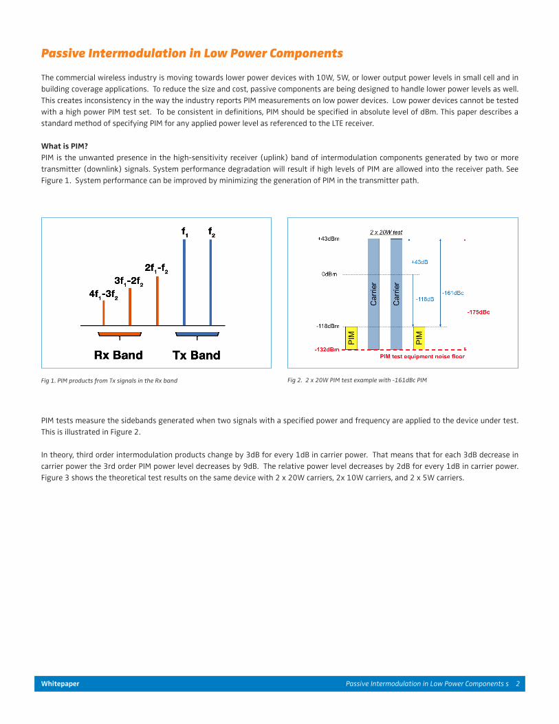
What is PIM? PIM is the unwanted presence in the high-sensitivity receiver (uplink) band of intermodulation components generated by two or more transmitter (downlink) signals. System performance degradation will result if high levels of PIM are allowed into the receiver path. See Figure 1. System performance can be improved by minimizing the generation of PIM in the transmitter path.
Passive Intermodulation in Low Power Components
Fig 1. PIM products from Tx signals in the Rx band Fig 2. 2 x 20W PIM test example with -161dBc PIM
PIM tests measure the sidebands generated when two signals with a specified power and frequency are applied to the device under test. This is illustrated in Figure 2.
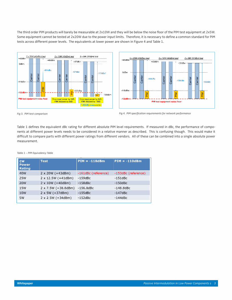
In theory, third order intermodulation products change by 3dB for every 1dB in carrier power. That means that for each 3dB decrease in carrier power the 3rd order PIM power level decreases by 9dB. The relative power level decreases by 2dB for every 1dB in carrier power. Figure 3 shows the theoretical test results on the same device with 2 x 20W carriers, 2x 10W carriers, and 2 x 5W carriers.
Whitepaper Passive Intermodulation in Low Power Components s 3
Fig 3. PIM test comparison Fig 4. PIM specification requirements for network performance
Table 1 – PIM Equivalency Table
The third order PIM products will barely be measurable at 2x10W and they will be below the noise floor of the PIM test equipment at 2x5W.Some equipment cannot be tested at 2x20W due to the power input limits. Therefore, it is necessary to define a common standard for PIM tests across different power levels. The equivalents at lower power are shown in Figure 4 and Table 1.
Table 1 defines the equivalent dBc rating for different absolute PIM level requirements. If measured in dBc, the performance of compo-nents at different power levels needs to be considered in a relative manner as described. This is confusing though. This would make it difficult to compare parts with different power ratings from different vendors. All of these can be combined into a single absolute power measurement.
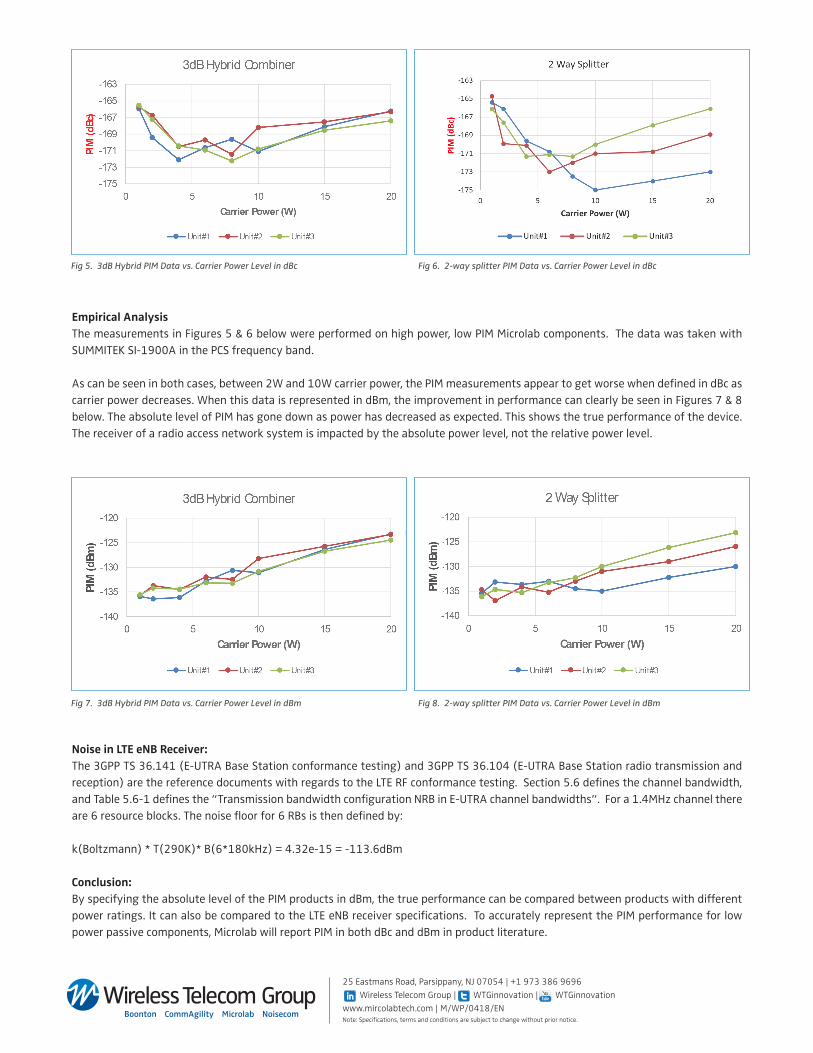
Empirical AnalysisThe measurements in Figures 5 & 6 below were performed on high power, low PIM Microlab components. The data was taken with SUMMITEK SI-1900A in the PCS frequency band.
As can be seen in both cases, between 2W and 10W carrier power, the PIM measurements appear to get worse when defined in dBc as carrier power decreases. When this data is represented in dBm, the improvement in performance can clearly be seen in Figures 7 & 8 below. The absolute level of PIM has gone down as power has decreased as expected. This shows the true performance of the device. The receiver of a radio access network system is impacted by the absolute power level, not the relative power level.
Fig 5. 3dB Hybrid PIM Data vs. Carrier Power Level in dBc Fig 6. 2-way splitter PIM Data vs. Carrier Power Level in dBc
Fig 7. 3dB Hybrid PIM Data vs. Carrier Power Level in dBm Fig 8. 2-way splitter PIM Data vs. Carrier Power Level in dBm
Noise in LTE eNB Receiver:The 3GPP TS 36.141 (E-UTRA Base Station conformance testing) and 3GPP TS 36.104 (E-UTRA Base Station radio transmission and reception) are the reference documents with regards to the LTE RF conformance testing. Section 5.6 defines the channel bandwidth, and Table 5.6-1 defines the “Transmission bandwidth configuration NRB in E-UTRA channel bandwidths”. For a 1.4MHz channel there are 6 resource blocks. The noise floor for 6 RBs is then defined by: k(Boltzmann) * T(290K)* B(6*180kHz) = 4.32e-15 = -113.6dBm Conclusion:By specifying the absolute level of the PIM products in dBm, the true performance can be compared between products with different power ratings. It can also be compared to the LTE eNB receiver specifications. To accurately represent the PIM performance for low power passive components, Microlab will report PIM in both dBc and dBm in product literature.
25 Eastmans Road, Parsippany, NJ 07054 | +1 973 386 9696 Wireless Telecom Group | WTGinnovation | WTGinnovationwww.mircolabtech.com | M/WP/0418/EN Note: Specifications, terms and conditions are subject to change without prior notice.