1 INTERNATIONAL TOVS STUDY CONFERENCE, 4-10 October 2006, Maratea J. PLA - CNES PASSIVE MICROWAVE PROTECTION: IMPACT OF RFI INTERFERENCE ON SATELLITE PASSIVE OBSERVATIONS Jean PLA CNES, Toulouse, France Frequency manager
Transcript
1INTERNATIONAL TOVS STUDY CONFERENCE, 4-10 October 2006, Maratea J. PLA - CNES
PASSIVE MICROWAVE PROTECTION: IMPACT OF RFI INTERFERENCE ON SATELLITE PASSIVE
OBSERVATIONS
PASSIVE MICROWAVE PROTECTION: IMPACT OF RFI INTERFERENCE ON SATELLITE PASSIVE
OBSERVATIONS
Jean PLACNES, Toulouse, France
Frequency manager
2INTERNATIONAL TOVS STUDY CONFERENCE, 4-10 October 2006, Maratea J. PLA - CNES
Description of the agenda items 1.2 and 1.20 forthe next WRC-2007Proposed “best” method to solve both agenda items
Impact of wrong or missing data
Examples of RFI at 6 and 10.6 GHz
Conclusion
Summary
3INTERNATIONAL TOVS STUDY CONFERENCE, 4-10 October 2006, Maratea J. PLA - CNES
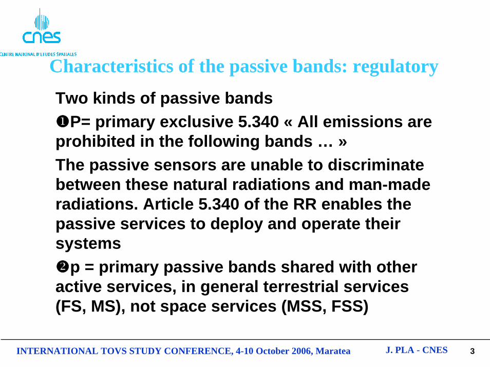
Characteristics of the passive bands: regulatory
Two kinds of passive bandsP= primary exclusive 5.340 « All emissions are
prohibited in the following bands … »The passive sensors are unable to discriminate between these natural radiations and man-made radiations. Article 5.340 of the RR enables the passive services to deploy and operate their systems
p = primary passive bands shared with other active services, in general terrestrial services (FS, MS), not space services (MSS, FSS)
4INTERNATIONAL TOVS STUDY CONFERENCE, 4-10 October 2006, Maratea J. PLA - CNES
Objective of the passive bands1400-1427 MHz: salinity (ocean), soil moisture
wind23.6-24 GHz: total content of water vapour 31.3-31.5 GHz: the lowest cumulated effects due
to oxygen and water vapour in the vicinity of the 50 GHz band. Optimum window channel to see the Earth’s surface: reference for the other channels.36-37 GHz: cloud liquid water, vegetation
structure, surface roughness50.2-50.4 GHz: temperature profile
5INTERNATIONAL TOVS STUDY CONFERENCE, 4-10 October 2006, Maratea J. PLA - CNES
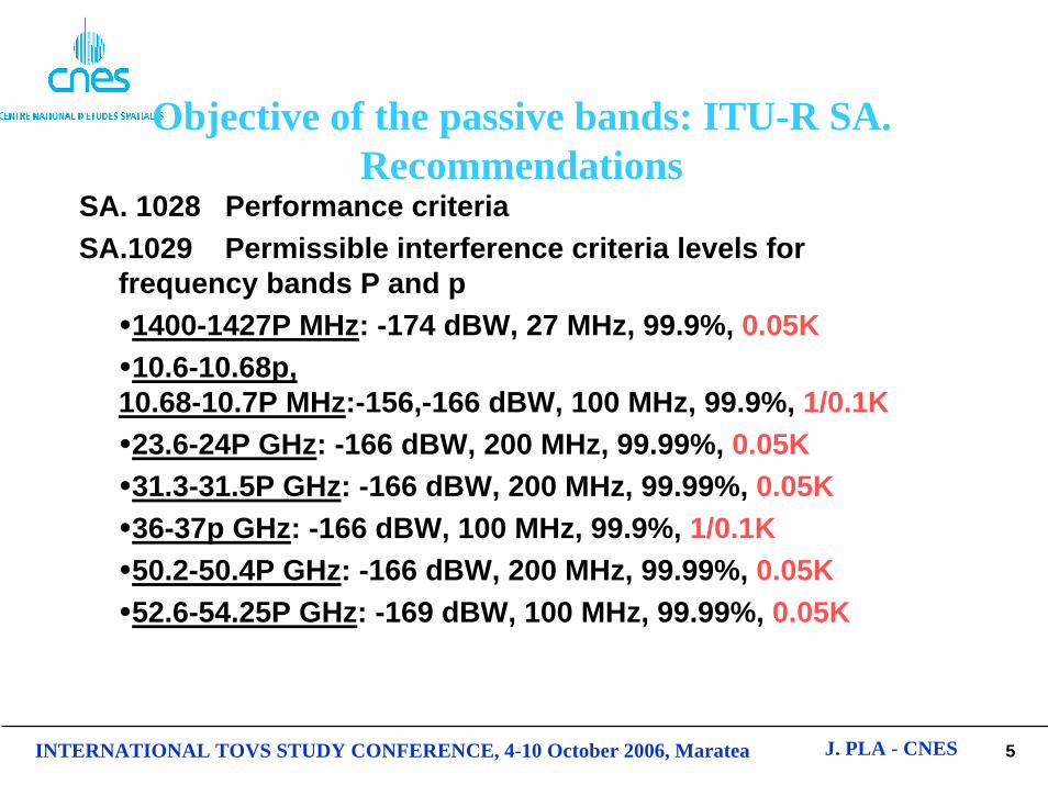
Objective of the passive bands: ITU-R SA. Recommendations
SA. 1028 Performance criteriaSA.1029 Permissible interference criteria levels for
frequency bands P and p 1400-1427P MHz: -174 dBW, 27 MHz, 99.9%, 0.05K10.6-10.68p,
6INTERNATIONAL TOVS STUDY CONFERENCE, 4-10 October 2006, Maratea J. PLA - CNES
Objective of the passive bands: Data availabilityData availability is the percentage of area or time for which accurate data is available for a specified sensor measurement area or sensor measurement time.
For a 99.99% data availability, the measurement area is a square on the Earth of 2,000,000 km2, unless otherwise justified.
For a 99.9% data availability, the measurement area is a square on the Earth of 10,000,000 km2 unless otherwise justified.
For a 99% data availability the measurement time is 24 hours, unless otherwise justified.
7INTERNATIONAL TOVS STUDY CONFERENCE, 4-10 October 2006, Maratea J. PLA - CNES
Agenda item 1.2 of WRC-07
• to invite ITU-R to conduct sharing analyses between the EESS (passive) and the SRS (passive) on one hand and the fixed and mobile services on the other hand in the band 10.6-10.68 GHz to determine appropriate sharing criteria
• to invite ITU-R to conduct sharing studies between the passive services and the fixed and mobile services in the band 36-37 GHz in order to define appropriate sharing criteria
8INTERNATIONAL TOVS STUDY CONFERENCE, 4-10 October 2006, Maratea J. PLA - CNES
Agenda item 1.2 of WRC-07• For the bands 10.6-10.68 GHz and 36-37 GHz, the corresponding
radiometers are all conical scan (rotating).
Useful scan-angle
Usefulswat h
IFOV
Conical scanaround
nadir direct ion
Incidence
Sat ellit e subt rack
Geometry of conically scanned microwave radiometer
Pixel
9INTERNATIONAL TOVS STUDY CONFERENCE, 4-10 October 2006, Maratea J. PLA - CNES
Agenda item 1.2 of WRC-07
• For both bands 10.6-10.68 GHz and 36-37 GHz, dynamic simulations are conducted for specific passive sensors (AMSR-E, AMSR, CMIS, MADRAS) and for typical deployments of terrestrial systems.
• Example of a dynamic simulation
-220 -210 -200 -190 -180 -170 -160 -15010
-3
10-2
10-1
100
101
102
Received power at the radiometer
Cor
resp
ondi
ng c
umul
ativ
e %
10INTERNATIONAL TOVS STUDY CONFERENCE, 4-10 October 2006, Maratea J. PLA - CNES
Agenda item 1.2 of WRC-07• The received power are compared to the thresholds
contained in Recommendation SA.1029-2 according to a cumulative corresponding % of 0.1 for a limited area of 10000000 km2
• Proposed methodology in the Conference preparatory text: development of sharing criteria based on single entry emission limits to be included in a footnote of Article 5 of the Radio Regulations. Those limits are suggested to be non-retroactive for terrestrial active systems brought into use before WRC-07.
11INTERNATIONAL TOVS STUDY CONFERENCE, 4-10 October 2006, Maratea J. PLA - CNES
Agenda item 1.2 of WRC-07: examples of RFI at 10.6 GHz
12INTERNATIONAL TOVS STUDY CONFERENCE, 4-10 October 2006, Maratea J. PLA - CNES
Agenda item 1.2 of WRC-07: impact of RFI at 10.6 GHz, lack of data
Same areas of the world are corrupted by man made RFI in the band 10.6-10.68 GHz. It means that some areas of the world will suffer from a lack of data, since it is acknowledged that those corresponding data are totally unusable, taking into account the existing high level of interference.The question is: what is the impact of this lack of data on the overall output products if some data are systematically excluded on the same geographic areas? Are the output data still acceptable or reliable?
13INTERNATIONAL TOVS STUDY CONFERENCE, 4-10 October 2006, Maratea J. PLA - CNES
Agenda item 1.20 of WRC-07
• to consider the results of studies, and proposal for regulatory measures, if appropriate, regarding the protection of the Earth exploration-satellite service (passive) from unwanted emissions of active services in accordance with Resolution 738 (WRC-03)
14INTERNATIONAL TOVS STUDY CONFERENCE, 4-10 October 2006, Maratea J. PLA - CNES
Agenda item 1.20 of WRC-07
Bande attribuée au SETS (passive) Bande attribuée à un service actif Service actif
1 400-1 427 MHz 1 350-1 400 MHz Service fixe (SF), service mobile (SM) et service de
radiolocalisation (RL)
1 400-1 427 MHz 1 427-1 429 MHz SF, SM (sauf mobile aéronautique) et service de
recherche spatiale (Terre vers espace)
1 400-1 427 MHz 1 429-1 452 MHz SF et SM
23,6-24 GHz 22,55-23,55 GHz Service inter-satellites
31,3-31,5 GHz 30-31 GHz SFS (Terre vers espace)
50,2-50,4 GHz1 50,4-51,4 GHz1 SFS (Terre vers espace)1
50,2-50,4 GHz1 47,2-50,2 GHz (Régions 2 et 3)
49,44-50,2 GHz1 (Région 1)
SFS1
1 LES ÉTUDES RELATIVES À CETTE BANDE DOIVENT TENIR COMPTE DU NUMÉRO 5.340.1 DU RÈGLEMENT DES RADIOCOMMUNICATIONS.
15INTERNATIONAL TOVS STUDY CONFERENCE, 4-10 October 2006, Maratea J. PLA - CNES
Agenda item 1.20 of WRC-07: unwanted emission problem
The boundary between the out-of-band and spurious domains occurs at frequencies that are indicated in Figure 1: in general, the boundary, on either side of the centre frequency of the emission, occurs at a separation of 250% of the necessary bandwidth, or at 2.5 BN.
•
FIGURE 1 Out-of-band and spurious domains
Unwanted emissions Unwanted emissions
Spurious domainSpurious domain Out-of-banddomain
Out-of-banddomain
Necessarybandwidth
Frequency of the emission
Boundary of the spurious domainLimits of the necessary bandwidth
16INTERNATIONAL TOVS STUDY CONFERENCE, 4-10 October 2006, Maratea J. PLA - CNES
SATELLITES FOR THE BANDS 24, 31, 50 GHZ
IFOV: 1.1° 83° re.nadir
Cold calibration:83° re.nadir90° re.orbit plane
Field of view:Cross-track,+/- 50° re.nadir 50°50°
EESS orbit850 km alt.
Nadir direction
ORBITAL CONFIGURATION OF PUSH-BROOM PASSIVE SOUNDER
Sub-orbital track
Swath width2300 km
17INTERNATIONAL TOVS STUDY CONFERENCE, 4-10 October 2006, Maratea J. PLA - CNES
Agenda item 1.20 of WRC-07: representation of unwanted emission spectra
• Use of RR No. 1.153 the unwanted emission power in the passive band to be no greater than 0.5% of the total mean power of the emission (23 dB attenuation).
• Recommendation ITU-R SM.1541 provides a worst-case analysis in which the OOB emissions from the active service are overstated.
• Usage of more realistic methodologies– Modulation filtering: DVB-S standard (40 dB attenuation) or usage of
more traditional waveforms (20 dB attenuation) such as
– Post-modulation filtering in most cases: between 25 and 40 dB attenuation
• Total expected attenuation (depending on bandwidth of the activeservice) within the adjacent passive band: between 23 and 80 dB.
2sin
⎟⎟⎠
⎞⎜⎜⎝
⎛fT
fTππ
18INTERNATIONAL TOVS STUDY CONFERENCE, 4-10 October 2006, Maratea J. PLA - CNES
Agenda item 1.20 of WRC-07: dynamic simulations, methodologies
Like agenda item 1.2, dynamic simulations are conducted in a co-frequency mode.How much is the interference threshold exceeded according to ITU-R Recommendations?The bandwidth scaling factor compares the necessary bandwidth Bn of the active service to the EESS (passive) bandwidth Bp.Attenuation provided by Recommendation ITU-R SM.1541 or other modulation/ post-modulation filtering (see before).
19INTERNATIONAL TOVS STUDY CONFERENCE, 4-10 October 2006, Maratea J. PLA - CNES
Method to solve the agenda item 1.20 of WRC-07
Proposed methodology in the Conference preparatory text: development of a single entry emission limit for each corresponding active service within the EESS (passive) band to be included in a footnote of Article 5 of the Radio Regulations. Those limits are suggested to be non-retroactive for active systems brought into use before WRC-07.
20INTERNATIONAL TOVS STUDY CONFERENCE, 4-10 October 2006, Maratea J. PLA - CNES
Agenda item 1.20 of WRC-07, impact of RFI at 1.4 GHz (simulation SMOS type) (1/2)
Input brightness temperature map depicting a segment of the Yellow Rivernear Xi'an, a city located in the north-west of China
21INTERNATIONAL TOVS STUDY CONFERENCE, 4-10 October 2006, Maratea J. PLA - CNES
Agenda item 1.20 of WRC-07, impact of RFI at 1.4 GHz (simulation SMOS type) (2/2)
Reconstructed brightness temperature map with RFI using
an average level of -10 dBW
22INTERNATIONAL TOVS STUDY CONFERENCE, 4-10 October 2006, Maratea J. PLA - CNES
CONCLUSION (1/3)• IMPACT OF HIGH LEVEL OF INTERFERENCE
Lack of data what is the impact of this lack of data on the overall output products if some data are systematically excluded on the same geographic areas? Are the output data still acceptable or reliable?
• IMPACT OF UNDETECTABLE LEVEL OF INTERFERENCEThis is a situation that is more than likely to occur over large areas. It would imply that corrupted data will be actually used within NWP (Numerical Weather Prediction) models or other models making usage of both data derived from satellite and terrestrial observation. In that case, the data are actually used within the model because the data were initially known to be acceptable (or assumed to be derived from natural emission only). What happens on the weather forecast (or other similar output products) if, for example, some EESS satellite pixels are corrupted with wrong data due to non-natural emissions at 24 or 50 GHz?
23INTERNATIONAL TOVS STUDY CONFERENCE, 4-10 October 2006, Maratea J. PLA - CNES
CONCLUSION (2/3)
• Method able to adequately protect the corresponding passive bands proposes hard limits (in-band ou out-of band): may constrain the existing or future systems in operation in those bands. Some operators already explained the quantitative consequences of a possible limitation of the power of the fixed links.
• The ITU-R working party in charge of the passive sensors already provides a qualitative explanation of the consequences of various levels of aggregate interference received by a passive sensor.
24INTERNATIONAL TOVS STUDY CONFERENCE, 4-10 October 2006, Maratea J. PLA - CNES
CONCLUSION (3/3)• Urgent matter to get a quantitative explanation of
those various levels of degradation. It is still possible to keep arguing that it is not so obvious to derive this kind of information since complex algorithms are needed to model the atmosphere which is known to be very unstable by nature. It is true that it is hard to distinguish between weak radio frequency interference and naturally geophysical variability.
• Space and meteorological agencies have to bring evidence that interference exceeding the interference quoted in RS.1029-2 will disrupt the existing or planned algorithms.