16
Page 1 of 16 PAT-4 POWER SUPPLY ASSEMBLY MANUAL © 2013 AkitikA, LLC All rights reserved Revision 1p08 September 1, 2013

Page 1 of 16
PAT-4 POWER SUPPLY
ASSEMBLY MANUAL
© 2013 AkitikA, LLC
All rights reserved
Revision 1p08 September 1, 2013

Page 2 of 16
Table of Contents Table of Contents................................................................................................................ 2
Table of Figures .................................................................................................................. 2
Section 1: About This Manual ............................................................................................ 3
Other PAT-4 Upgrades ................................................................................................... 3
Who Should Attempt these Projects? ............................................................................. 3
Tools You’ll Need........................................................................................................... 4
Project Overview ............................................................................................................ 4
Section 2: Building the Power Supply PC Board ............................................................... 5
First, Get A Soup Bowl! ............................................................................................. 5
Install the Resistors ......................................................................................................... 5
Resistor Notes ............................................................................................................. 7
Install the Diodes ............................................................................................................ 8
Diode Notes ................................................................................................................ 8
Install the TO-92 Package Transistors............................................................................ 8
Install the TO-92 Package Integrated Circuits................................................................ 9
Install the TO-220 Power Transistors ............................................................................. 9
Install the Capacitors..................................................................................................... 10
Remove the Old Power Supply................................................................................. 11
Install the New Power Supply....................................................................................... 13
Connect the New Power Supply ............................................................................... 13
Final Test and Assembly............................................................................................... 14
Schematic.................................................................................................................. 15
Resistor Color Code...................................................................................................... 16
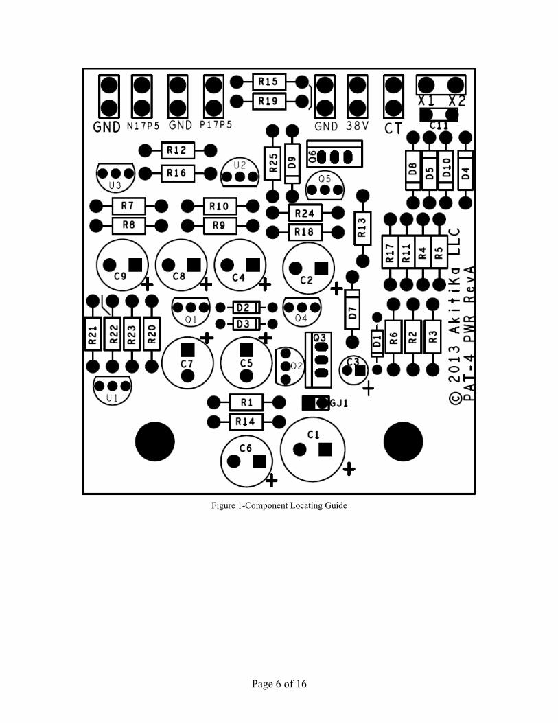
Table of Figures Figure 1-Component Locating Guide ................................................................................. 6
Figure 2-Front and Back views of Q6 mounted on heat sink ............................................. 9
Figure 3-Q3 with resistor added to the emitter ................................................................. 10
Figure 4-Showing wires to cut and screws to remove ...................................................... 12
Figure 5-Mounting the power supply to the PAT-4.......................................................... 13
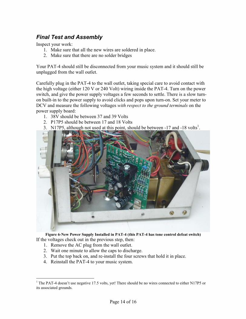
Figure 6-New Power Supply Installed in PAT-4 (this PAT-4 has tone control defeat
switch)............................................................................................................................... 14
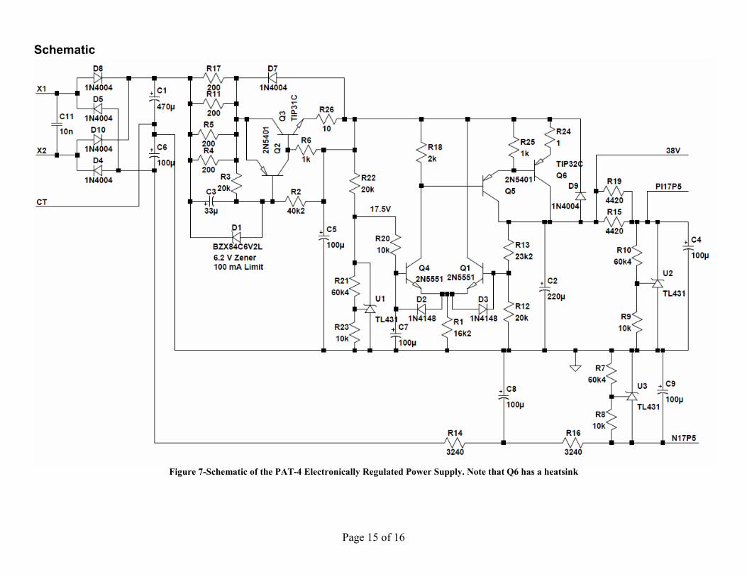
Figure 7-Schematic of the preamp high level stage showing the addition of the tone
control switch.................................................................................................................... 15
Figure 8-demonstrating the resistor color code ................................................................ 16

Page 3 of 16
Section 1: About This Manual This manual gives the information you need to build and install a replacement power
supply in the Dynaco PAT-4 Preamp. Compared to the original power supply, the
replacement power supply should give better sound. That’s because the outputs are
electronically regulated. That means:
• The output voltage isn’t affected by normal changes in input line voltage (e.g.
changes in line voltages when appliances turn on and off).
• The outputs don’t change with changing signal load produced by changes in the
musical signal. That keeps the amplifier stage’s operating point more consistent,
and reduces distortion.
• The outputs have less noise and hum. That can reduce the hum and noise that
appears at the preamp’s outputs.
The layout of the power supply is in many ways superior to the original. For example, the
impulsive noise and current path through the diodes and main filter caps has much
smaller loop area than the original power supply arrangement. That diminishes hum
fields when you’ve installed the new power supply.
Other PAT-4 Upgrades
As of this writing, the following other PAT-4 upgrades are available from
Updatemydynaco, a division of Akitika LLC:
• Blue Light Kit
• Line Amp Distortion Reducer
• Tone Control Switch
The Line Amp Distortion Reducer drops the distortion of the Line Amp by a factor of
ten. The Line Amp is the stage that includes the volume and tone controls. All sound
from the preamp passes through the Line Amp. This upgrade should make everything
played through the PAT-4 sound better.
The Tone Control Switch replaces the existing Hi Filter switch with a two position rotary
switch. In the OFF position, the tone controls are disabled. In the 15 position, tone
controls maintain their normal function. After this modification, the other two positions
of the HI FILTER switch (10 and 7) are not available.
These upgrades can be installed in any combination.
Who Should Attempt these Projects?
You can build this kit if you can:
1. solder (using normal rosin core solder and a soldering iron).
2. use simple hand tools like screwdrivers, wire cutters, and pliers.
3. read and follow directions.
It helps if you:
Page 4 of 16
1. know a bit about electronics, or
2. have a friend who knows a bit about electronics
3. can get to YouTube to watch a few helpful videos about the assembly process (not
available as of this version of the manual)
Tools You’ll Need
You’ll need the following tools:
1. flat blade screwdriver for #6 screws
2. needle nose pliers (helpful, but not strictly necessary)
3. pencil type soldering iron of 25 to 50 Watts (no huge honking soldering guns or
blowtorches)
4. wire cutters and strippers
5. Magnifying glass, if you’re over 42!
Project Overview
The project consists of the following steps:
1. Building the new power supply circuit board.
2. Labeling some wires, desoldering them, and then removing the old power supply
components.
3. Installing the new power supply, testing its outputs, and re-assembling the
preamp.
By purchasing, using, or assembling this kit, you have agreed to hold AkitikA, LLC
harmless for any injuries you may receive in its assembly and/or use. To prevent injuries:
• Wear safety glasses when soldering to prevent eye injuries.
• Always unplug the power before working on the amplifier.
• Large capacitors hold lots of energy for a long time. Before you put your hands
into the amplifier:
o Pull the AC plug!
o Wait 1 full minute for the capacitors to discharge!
• Remove jewelry and rings from your hands and wrists, or anything that might
dangle into the amplifier.
• If working in the amplifier, keep one hand in your pocket, especially if you’re
near the power supply or power supply wires. This can prevent serious shocks.
• Build with a buddy nearby. If you’ve ignored all the previous advice, they can
dial 911 or get you to the hospital.

Page 5 of 16
Section 2: Building the Power Supply PC Board
First, Get A Soup Bowl!
A wide, flat soup bowl makes a great holder for the parts that you’ll install into the
printed circuit board. So get that soup bowl, then open the parts envelope, and carefully
transfer the parts into the soup bowl. Keep the parts envelope near the soup bowl as you
do this. This keeps them from bouncing out of the soup bowl and into the carpet, never to
be seen again.
In general, you’ll start with the components that lay closest to the board, working your
way toward the taller components. You will:
1. Install the resistors
2. Install the diodes (polarity matters!)
3. Install the small signal transistors and U1-U3 (all in TO-92 packages)
4. Install the power transistors
5. Install the tall capacitors (polarity matters!)
The silk screened (component side) of the PCB shows the locations for the various
components. Those indications are placed a little to the side of the component locations
to allow you to identify components after assembly. If you’re ever in doubt about the
correction locations, refer to the component locating guide, Figure 1. This very clearly
shows all the component locations.
Install the Resistors
In general, you install the resistors by placing the body on the silk screen side of the
board, and the leads through the indicated holes. Bend the leads over on the back of the
board to keep the resistors from falling out until you solder them in place. Try to bend the
leads in a direction that avoids solder bridges between traces that should remain
disconnected.
We recommend the following procedure:
1. Insert all the resistors of the same value, e.g. R4, R5, R11, and R17.
2. Bend the leads as described above.
3. Solder the leads on the back of the board.
4. Clip the leads.
Place a check mark � in the “Done(�)” column as you complete each step.
Page 6 of 16
Figure 1-Component Locating Guide

Page 7 of 16
Designation Value Color Code Done(�)
R4 200 Red, Black, Black, Black, Brown
R5 200 Red, Black, Black, Black, Brown
R11 200 Red, Black, Black, Black, Brown
R17 200 Red, Black, Black, Black, Brown
R3 10K Brown, Black, Black, Red, Brown
R8 10K Brown, Black, Black, Red, Brown
R9 10K Brown, Black, Black, Red, Brown
R20 10K Brown, Black, Black, Red, Brown
R23 10K Brown, Black, Black, Red, Brown
R14 3240 Orange, Red, Yellow, Brown, Brown
R16 3240 Orange, Red, Yellow, Brown, Brown
R6 1K Brown, Black, Black, Brown, Brown
R25 1K Brown, Black, Black, Brown, Brown
R12 20K Red, Black, Black, Red, Brown
R22 20K Red, Black, Black, Red, Brown
R7 60K4 Blue, Black, Yellow, Red, Brown
R10 60K4 Blue, Black, Yellow, Red, Brown
R21 60K4 Blue, Black, Yellow, Red, Brown
R15 4420 Yellow, Yellow, Red, Brown, Brown
R19 4420 Yellow, Yellow, Red, Brown, Brown
R1 16K2 Brown, Blue, Red, Red, Brown
R24 1 Ohm Brown, Black, Black, Silver, Brown
R13 23K2 Red, Orange, Red, Red, Brown
R18 2K Red, Black, Black, Brown, Brown
R2 40K2 Yellow, Black, Red, Red, Brown
Resistor Notes
• All the resistors are ¼ W, 1%, Metal Film
• K stands for 1000. Thus, 60K4 is a short-hand that means 60,400 Ohms. Some
people like to convert the K notation to a number by:
1. Replace the K by a decimal point.
2. Multiply the resulting number by 1000.
• Resistor orientation does not matter.
• Feel free to use a DMM (digital multi-meter) to confirm the resistor values before
installation.
• You will have a 10 Ohm resistor left over at the end of this section, R26. It will
be used later in a special mounting arrangement with Q3.

Page 8 of 16
Install the Diodes
Be careful! Diodes have a polarity. Make sure the band on the diode aligns with
the banded end of the silk screen!
Designation Value Marking, type Done(�)
D4 1N4004 4004, 400 PIV 1 Amp
D5 1N4004 4004
D7 1N4004 4004
D8 1N4004 4004
D9 1N4004 4004
D10 1N4004 4004
Here’s what the 1N4004 diodes look like (not to scale). The package type is known as a
DO-41. The body is black, with a white stripe:
Be careful! Diodes have a polarity. Make sure the band on the diode aligns with
the banded end of the silk screen!
Designation Value Marking, Type Done(�)
D1 TZX6V2C TZX6V2, 6.2 Volt Zener, 0.5 Watt
D2 1N4148 The number 48 is visible, 75 PIV, 100 mA
D3 1N4148 The number 48 is visible, 75 PIV, 100 mA
D1-D3 have a glass body. They are packaged in the DO-35 package, a smaller package
than the 1N4004’s.
Diode Notes
The designator D6 is not used.
Install the TO-92 Package Transistors
The TO-92 package looks like this:
In some cases, the leads may be bent as the picture above shows. In other cases, you may
have to spread the outside leads a bit to make it easier to insert them into the board.
Orient the transistor so its body shape matches the silk-screen outline. Leave the top of
the transistor about ½” off the board! The lead length prevents stress on the body and
keeps the transistor safe from too much heat during the soldering operation.

Page 9 of 16
Designation Type Description Done? (�)
Q1 2N5551, TO-92 150 V NPN bipolar transistor
Q4 2N5551, TO-92 150 V NPN bipolar transistor
Q2 2N5401, TO-92 150 V PNP bipolar transistor
Q5 2N5401, TO-92 150 V PNP bipolar transistor
Don’t use too much solder on the transistor leads. This is one place where the spacing is
close enough that extra solder might cause short circuit between two leads on a given
transistor. Note that Q4’s collector and base are connected by the circuit board.
Install the TO-92 Package Integrated Circuits
Although the package looks the same as the transistors, the three integrated circuits
installed in this step are actually voltage regulators. You may have to spread the outside
leads a bit to make it easier to insert them into the board.
Orient the transistor so its body shape matches the silk-screen outline. Leave the top of
the transistor about ½” off the board! The lead length prevents stress on the body and
keeps the transistor safe from too much heat during the soldering operation.
Designation Type Description Done? (�)
U1 TL431 2.5 V adjustable shunt regulator
U2 TL431 2.5 V adjustable shunt regulator
U3 TL431 2.5 V adjustable shunt regulator
Don’t use too much solder on the integrated circuit leads. This is one place where the
spacing is close enough that extra solder might cause short circuit between two leads on
a given transistor.
Install the TO-220 Power Transistors
The TO-220 package looks like this (there may be some variation in the plastic molding):
Each of the power transistors must be specially prepared before installation.
• Install a heat sink on Q6, the TIP32C PNP power transistor before you solder it
into the board. Use a 6-32.x1/4” sem-screw (has a built-in lock-washer) and a 6-
32 keps nut (also has a built in lock washer). No thermal compound is needed.
Figure 2-Front and Back views of Q6 mounted on heat sink

Page 10 of 16
• Q3, a TIP31C power transistor, must be assembled with a 10 Ohm ¼ Watt
resistor, R26, formed onto the emitter lead in the manner shown in Figure 3.
o Bend the emitter lead, as shown (don’t bend it repeatedly, it may break)
o Wrap the resistor lead around the bend transistor lead
o Form the resistor lead so the resulting three leads (the original base,
collector, and the resistor extension of the emitter will drop into the PCB
Figure 3-Q3 with resistor added to the emitter
Orient the transistor so the position of the metal tab matches the silk-screen outline. The
shoulder of the leads naturally limits insertion to the correct height. Solder the outside
leads first and assure that the transistors are straight, then solder the center lead.
Designation Type Description Done? (�)
Q3 TIP31C NPN transistor, 100 V
Q6 TIP32C PNP transistor, 100 V
Inspect your work for the absence of solder bridges when you’re done.
Install the Capacitors
Now, the medium tall polarized electrolytic capacitors:
Designation Value Marking Done? (�)
C1 470 µF, 63 V 470 µF, 63 V, and minus sign for polarity
C2 220 µF, 63 V 220 µF, 63 V, and minus sign for polarity
C3 33 µF, 35 V 33 µF, 35 V, and minus sign for polarity
C4 100 µF, 63 V 100 µF, 63 V, and minus sign for polarity
C5 100 µF, 63 V 100 µF, 63 V, and minus sign for polarity
C6 100 µF, 63 V 100 µF, 63 V, and minus sign for polarity
C7 100 µF, 63 V 100 µF, 63 V, and minus sign for polarity
C8 100 µF, 63 V 100 µF, 63 V, and minus sign for polarity
C9 100 µF, 63 V 100 µF, 63 V, and minus sign for polarity
And the non-polarized capacitor:
Designation Value Marking Done? (�)
C11 10 nF, 400V 10nk 400
Note: GJ1 is not used, and no connections to it are necessary.

Page 11 of 16
Remove the Old Power Supply
1. Disconnect the PAT-4 from your music system.
2. Unplug the power cord and allow the preamp to sit for one minute before moving
on.
Caution: Be sure that the preamp power is unplugged! 120 VAC can be lethal! 240 VAC
can be lethal!
3. Remove the 4 screws that hold the cover in place, 2 on the left side and 2 on the
right side.
4. Lift the cover straight up and set it aside in a safe place.
5. Get masking tape and a pen ready. You will be labeling the wires that you are
about to remove.
6. Refer to Figure 4. Desolder (or cut close to C29) the following wires from C29,
the tall 3-section capacitor. As you de-solder each wire, place a masking tape
label on the wire to aid re-assembly (if directed to do so).
a. 2 red wires connected to the semi-circle � section of the capacitor. Label
these two wires “P17P5”.
b. 2 red wires connected to the square � section of the capacitor. Label these
two wires 38V.
c. 1 red wire connected to the triangle ∆ section of the capacitor that comes
from the terminal strip holding diodes D1 and D2. Remove the other end
of this wire that connects to the terminal strip.
d. 2 black wires, one long, and one short, connected to one of the ground
terminals of C29.
e. 2 black wires, one long and one short, connected to the other of the ground
terminals of C29.
f. the transformer center-tap wire (typically has a red-yellow herringbone
pattern) that is connected to the third ground terminal of C29. Label this
wire CT.
7. Remove the two screws, nuts, and lock washers that hold C29’s clamp into the
chassis. Lift out C29.
8. Cut the other two low-voltage transformer (red) wires close to terminal strip
where they attach to D1 and D2. Label these wires X1 and X2. It doesn’t matter
which wire receives which label. D1, D2, and the terminal strip are unused after
the revised power supply is installed.

Page 12 of 16
Figure 4-Showing wires to cut and screws to remove

Page 13 of 16
Install the New Power Supply
1. Attach the mounting brackets to the assembled power supply PCB using two 6-
32x1/4” sems screws (sems screws have the captive lock washer). Make sure that
they’re both straight and tight.
Figure 5-Mounting the power supply to the PAT-4
2. Use the old mounting holes from C29 to fasten the brackets to the chassis. Figure
1Figure 6, on the next page, may also clarify this bit of the assembly.
Connect the New Power Supply
All of the power connections are made in the same fashion:
1. Strip ¼” of insulation off each of the wires to be connected.
2. Insert the wire from the solder side of the board, and solder it on the component
side of the board.
Twist the insulated portions of the three transformer wires together (X1, X2, and CT).
This minimizes the hum that these wires will radiate. Using the technique described
above, make the connections listed in the following table:
From Wire
label
To Power Supply Board Done?
(�)
First Transformer red wire X1 X1 eyelet
Second transformer red wire X2 X2 eyelet
Transformer Center tap wire (red/yellow) CT Bottom CT eyelet
Rear PC-16 eyelet 12 38V Bottom eyelet 38V
Front PC-16 eyelet 12 38V Top eyelet 38V
Rear PC-16 short gnd wire (eyelet 11) None Bottom gnd, next to 38V
Font PC-16 short gnd wire (eyelet 11) None Top gnd, next to 38V
Rear PC-16 eyelet 4 P17P5 Bottom eyelet P17P5
Front PC-16 eyelet 4 P17P5 Top eyelet P17P5
Rear PC-16 long gnd wire (eyelet 3) None Bottom gnd, next to P17P5V
Front PC-16 long gnd wire (eyelet 3) None Top gnd, next to P17P5V
Note that the N17PV eyelets and the grounds to the left of them will be unused.
Page 14 of 16
Final Test and Assembly
Inspect your work:
1. Make sure that all the new wires are soldered in place.
2. Make sure that there are no solder bridges
Your PAT-4 should still be disconnected from your music system and it should still be
unplugged from the wall outlet.
Carefully plug in the PAT-4 to the wall outlet, taking special care to avoid contact with
the high voltage (either 120 V or 240 Volt) wiring inside the PAT-4. Turn on the power
switch, and give the power supply voltages a few seconds to settle. There is a slow turn-
on built-in to the power supply to avoid clicks and pops upon turn-on. Set your meter to
DCV and measure the following voltages with respect to the ground terminals on the
power supply board:
1. 38V should be between 37 and 39 Volts
2. P17P5 should be between 17 and 18 Volts
3. N17P5, although not used at this point, should be between -17 and -18 volts1.
Figure 6-New Power Supply Installed in PAT-4 (this PAT-4 has tone control defeat switch)
If the voltages check out in the previous step, then:
1. Remove the AC plug from the wall outlet.
2. Wait one minute to allow the caps to discharge.
3. Put the top back on, and re-install the four screws that hold it in place.
4. Reinstall the PAT-4 to your music system.
1 The PAT-4 doesn’t use negative 17.5 volts, yet! There should be no wires connected to either N17P5 or
its associated grounds.
Page 15 of 16
Schematic
Figure 7-Schematic of the PAT-4 Electronically Regulated Power Supply. Note that Q6 has a heatsink

Page 16 of 16
Resistor Color Code
Figure 8-demonstrating the resistor color code
Here’s an extreme close-up of a ¼ W metal film 20K (20,000) Ohm resistor, designated
by the standard resistor color code.
The colors map to numbers:
Color Number
Black 0
Brown 1
Red 2
Orange 3
Yellow 4
Green 5
Blue 6
Violet 7
Gray 8
White 9
The color band positions have the following meaning:
Position Meaning
1 Left-most Digit (e.g. most significant)
2 Next digit to the right
3 Next digit to the right.
4 Number of zeros that follow the three digits, unless:
• Band 4 is gold => multiply by 0.1
• Band 4 is silver=> multiply by 0.01
**Yellow Tolerance:
• Brown =>1%
• Red => 2%
• Gold=> 5%
• Silver=>10%
• No band=>20%


