Research ArticlePath Planning and Control of a Quadrotor UAV Based on anImproved APF Using Parallel Search
Tianpeng Huang,1 Deqing Huang ,1 Na Qin,1 and Yanan Li2
1School of Electrical Engineering, Southwest Jiaotong University, Chengdu, China2Department of Engineering and Design, University of Sussex, Brighton BN1 9RH, UK
Correspondence should be addressed to Deqing Huang; [email protected]
Received 13 February 2021; Revised 2 June 2021; Accepted 22 June 2021; Published 15 July 2021
Control and path planning are two essential and challenging issues in quadrotor unmanned aerial vehicle (UAV). In this paper, anapproach for moving around the nearest obstacle is integrated into an artificial potential field (APF) to avoid the trap of localminimum of APF. The advantage of this approach is that it can help the UAV successfully escape from the local minimumwithout collision with any obstacles. Moreover, the UAV may encounter the problem of unreachable target when there are toomany obstacles near its target. To address the problem, a parallel search algorithm is proposed, which requires UAV tosimultaneously detect obstacles between current point and target point when it moves around the nearest obstacle to approachthe target. Then, to achieve tracking of the planned path, the desired attitude states are calculated. Considering the externaldisturbance acting on the quadrotor, a nonlinear disturbance observer (NDO) is developed to guarantee observation error toexponentially converge to zero. Furthermore, a backstepping controller synthesized with the NDO is designed to eliminatetracking errors of attitude. Finally, comparative simulations are carried out to illustrate the effectiveness of the proposed pathplanning algorithm and controller.
1. Introduction
In recent years, UAV has been used in various applications,such as infrastructure management [1], logistics delivery[2], and estimation of aboveground biomass of mangroveecosystems [3]. The implementation of UAV in all theseapplications requires it to follow a predefined path. In addi-tion, to achieve path tracking, a good control system shouldbe provided. Therefore, path planning with automatic obsta-cle avoidance and control are two essential tasks in UAV.
Research on UAV control has been extensively reportedin the literature. In [4], a proportional-integral-derivative(PID) controller is designed to accomplish altitude and atti-tude tracking for a quadrotor helicopter. A fuzzy PID controlmethod is proposed in [5], where the fuzzy rules are
employed to automatically adjust the three parameters ofPID controller. In [6, 7], an active disturbance rejection con-trol (ADRC) scheme is developed to achieve trajectory track-ing of a quadrotor UAV. PID and ADRC are model-freecontrol strategies, which have an advantage of a simple con-trol structure. However, it is difficult to tune the parametersof these two controllers.
In [8], an adaptive sliding mode control (SMC) is inves-tigated to stabilize a quadrotor system subject to unknownexternal disturbance. [9] presents a continuous SMCapproach to follow the predefined trajectories in positionand attitude channels for a four-rotor UAV. An adaptivefinite-time attitude tracking algorithm is applied to a quadro-tor in the presence of uncertainty and disturbance in [10]. In[11], a disturbance observer is integrated to H∞ technique to
HindawiInternational Journal of Aerospace EngineeringVolume 2021, Article ID 5524841, 14 pageshttps://doi.org/10.1155/2021/5524841
realize hovering control of a quadrotor. The robustness ofsuch a method has been verified by experiments. In [12],the differential flatness is used in tracking control of transla-tional and rotational movements of an UAV system consid-ering modeling uncertainty and disturbance. An adaptivelinear quadratic control strategy is proposed in [13] to stabi-lize three attitude angles of a quadrotor. To achieve trajectoryfollowing of position and attitude subsystems, a nonlineardisturbance observer- (NDO-) based backstepping controlleris proposed in [14], where the NDO is utilized to estimateexternal disturbance.
The bioinspired algorithms have been applied to path plan-ning of UAV. In [15], a chaotic artificial bee colony (ABC)method is developed to design a path in complex environ-ments. In [16], an ant colony optimization (ACO) algorithmis proposed to achieve trajectory planning for a UAV. [17] pre-sents a particle swarm optimization (PSO) algorithm to addresspath planning of UAV. Genetic algorithm (GA), as a popularoptimization algorithm, has been employed to plan a path inUAV [18]. Furthermore, a comparison of GA and PSO forreal-time path planning of UAV is carried out in [19], wherethe results indicate that, under the consideration of statisticalsignificance, the trajectories produced by GA are superior com-pared to that produced by PSO when using the same encoding.In [20, 21], a grey wolf optimizer is used to search a feasible andeffective path for a UAV. An improved fruit fly optimizationalgorithm is introduced in [22] to address the problem of pathplanning of multiple UAVs in 3D complicated environmentswith online changing tasks. In [23], a flower pollination algo-rithm based on neighborhood global learning is employed tocomplete route planning of a UAV. [24] offers an evolutionaryalgorithm based on a novel separate evolution strategy to planan optimized path for a single UAV. Furthermore, a con-strained differential evolution is put forward to achieve pathplanning of a UAV in [25].
Besides the aforementioned bioinspired intelligent algo-rithms, there are many effective strategies to solve the prob-lem of path planning of UAV. [26] studies a distributedmultiagent path planning algorithm for quadrotors indynamic environments. An energy-based path planningframework is used to improve flight endurance for a solar-powered UAV in [27]. A multiobjective path planning is pre-sented in [28] to design a feasible path for a UAV, wheresafety is considered in the proposed algorithm. [29] intro-duces a path planning system based on an elliptical tangentmodel to reduce computational burden for a quadrotorUAV in an unknown unstructured outdoor environment.In [30], a ground feature-oriented approach is investigatedto generate a suitable path for UAVmapping. Two path plan-ning algorithms are designed in [31], one of which is basedon the exact penalty method and successive convex approxi-mation, and the other adopts a heuristic approach. In addi-tion, [32] presents an improved A-star algorithm togenerate a path for target tracking of a UAV. In [33], a Vor-onoi diagram-based multiple UAV path planning method isproposed to cooperatively attack multiple targets in a staticenvironment. An improved rapidly exploring random tree(RRT) algorithm is introduced in [34] to realize 3D pathplanning of a UAV.
As an efficient path planning algorithm, APF has beenapplied to some scenarios, such as mobile robots [35, 36]and automated vehicles [37]. The traditional APF (TAPF)has two shortcomings, i.e., local minimum and unreachablegoal. To address these problems, the repulsive potential func-tion of TAPF is replaced by Gaussian function in [38]. How-ever, UAV still might fall into a local minimum using theimproved APF in [38] when obstacle is on the line connect-ing current position and target position. Moreover, whenmultiple obstacles are around target and repulsive gain islarge, the resultant repulsive forces might be equal to attrac-tive force, in which case UAV could not approach target.Motivated by the above analysis, a novel APF based on paral-lel search is proposed for path planning of UAV in this paper.
The main contributions of the paper are summarized asfollows:
(1) A parallel search algorithm is proposed to addresslocal minimum and unreachable target with obstaclesnearby in TAPF
(2) Compared with existing results of path planningalgorithms [34, 39, 40], a shorter path and less timeconsumption are obtained using the proposedalgorithm
(3) Compared with ADRC [6, 7], better tracking perfor-mance is obtained by the proposed controller basedon NDO with exponential convergence when follow-ing the planned path
The remainder of this paper is organized as follows. InSection 2, TAPF is introduced and the problems of local min-imum and unreachable goal of TAPF are analyzed. In Section3, a novel APF based on parallel search is presented. Section 4introduces the design of the observer and controller of thequadrotor. In Section 5, comparative simulations are con-ducted to verify the effectiveness of the proposed algorithmand controller. Section 6 concludes the work.
2. TAPF Applied to Path Planning of UAV
2.1. TAPF. APF is a virtual potential field in space, which con-sists of attractive potential field generated by target positionand repulsive potential field generated by obstacle. The UAVautomatically plans a path to destination under the influenceof attractive potential field and repulsive potential field.
Let Pcurðxcur, ycurÞ and Ptarðxtar, ytarÞ represent the cur-rent position and target position of the UAV, respectively.Then, the attractive potential field is given by
Ua Pcurð Þ = 12 kada Pcur, Ptarð Þ2, ð1Þ
where ka is a positive gain and daðPcur, PtarÞ is the minimumdistance between current position and the target position, ina 2D case defined as
da =ffiffiffiffiffiffiffiffiffiffiffiffiffiffiffiffiffiffiffiffiffiffiffiffiffiffiffiffiffiffiffiffiffiffiffiffiffiffiffiffiffiffiffiffiffiffiffiffiffiffiffiffixcur − xtarð Þ2 + ycur − ytarð Þ2
q: ð2Þ
2 International Journal of Aerospace Engineering
Input: the current position Pcurðxcur , ycurÞ of UAV, target position Ptarðxtar , ytarÞ, obstacles position;Output: The path to the target;
Calculate da;Update path matrix M⟵ Pcur;whileda > c (c is a small positive constant) do
Calculate attractive force Fa, using (2) and (5);Calculate repulsive force Fri, using (4) and (6);Calculate the components of attractive force along the x and y directions, respectively;Calculate the components of repulsive force along the x and y directions, respectively;Calculate the next point on the path Pnext according to the resultant of attractive force and repulsive force;Update M⟵ Pnext;
end while
Algorithm 1: Path planning algorithm based on TAPF
25
20Obstacle
15
15
Fr
Fa
x (m)
y (m
)
2520
10
10
5
50
0
Target
Figure 1: Scenario 1: the local minimum of TAPF with a single obstacle.
25
25
20
20
15
15
Obstacle2
Obstacle1
FaFr2
Fr1Fr
x (m)
y (m
)
10
10
5
50
0
Target
Figure 2: Scenario 1: the local minimum of TAPF with multiple obstacles.
3International Journal of Aerospace Engineering
Let Pobiðxobi , yobiÞ denote position of the ith obstacle,where i ∈N + . Then, the repulsive potential field of the ithobstacle is defined as
Uri Pcurð Þ =12 kri
1dri Pcur, Pobið Þ −
1d0
� �2dri ≤ d0,
0 dri > d0,
8><>:
ð3Þ
where kri and d0 are positive constants and driðPcur, PobiÞ isthe minimum distance between current position and the ithobstacle, in a 2D case defined as
It is worth noting that d0 in (3) shows the influence rangeof the repulsive potential field of obstacle. Obviously, theattractive potential field is global, while the repulsive poten-tial field is local. Furthermore, the attractive force from thetarget is obtained by (1)
Fa Pcurð Þ = kada Pcur, Ptarð Þ: ð5Þ
Meanwhile, the repulsive force of the ith obstacle isobtained from (3):
Fri Pcurð Þ = kri1dri
−1d0
� � 1dri
� �2dri ≤ d0,
0 dri > d0:
8><>: ð6Þ
Therefore, the path planning for UAV based on theTAPF algorithm is shown in Algorithm 1.
30
Obs2Obs1
Obs3
Obs4Obs5Fa
Fr3Fr2Fr1Fr5
Fr4
Fr
Target25
20
20 25 30
15
15
x (m)
y (m
)10
10
5
50
0
Figure 3: Scenario 1: the unreachable goal of TAPF.
30
30
25
25
Obs8Fr
Fr7Fr8 Fr1Fr2Fr3Fr4
Fr6Fr5
FaObs7
Obs6Obs5
Obs4Obs3Obs2
Obs1Target
20
20
x (m)
y (m
)
15
15
10
10
5
50
0
Figure 4: Scenario 2: the unreachable goal of TAPF.
4 International Journal of Aerospace Engineering
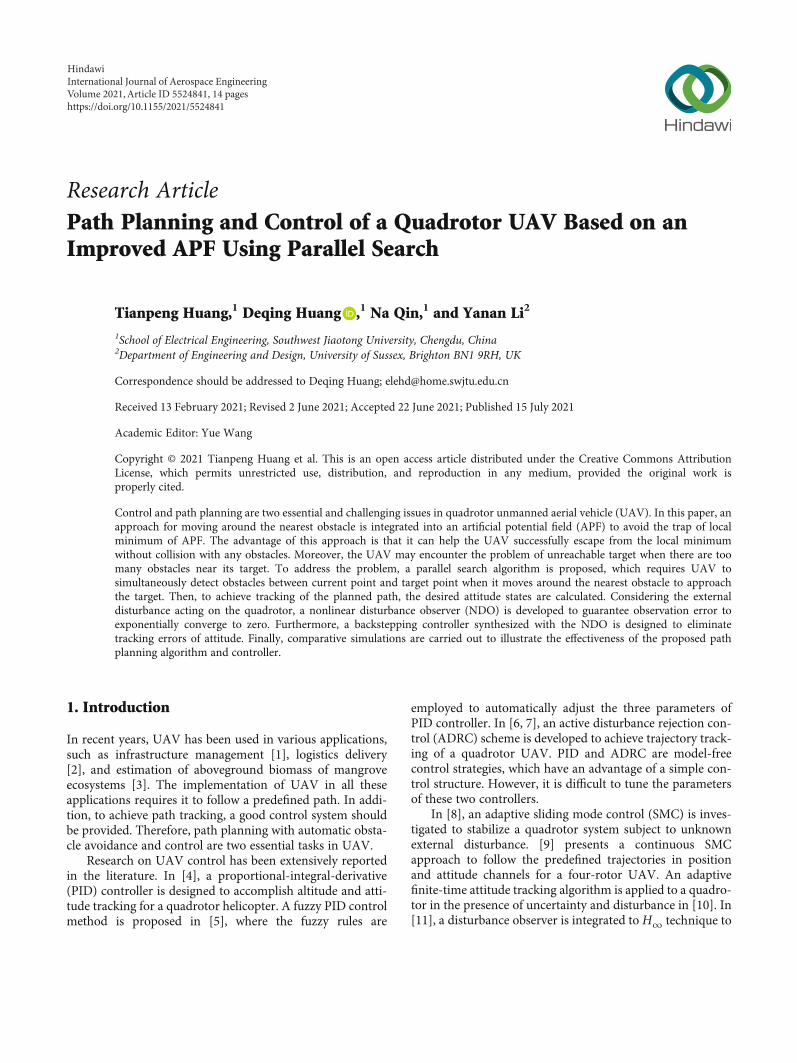
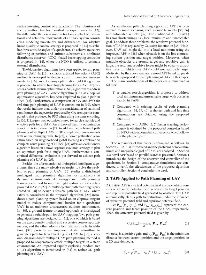
2.2. Local Minimum. The local minimum is an inherent dis-advantage of TAPF. When the attractive force and repulsiveforce reach a balance, the UAV would encounter a trap of alocal minimum, which means that the UAV stops movingtowards target, as shown in Figures 1 and 2, where Fa andFr represent the attractive force and resultant repulsive forceat the current position, respectively, and Fri, i = 1, 2, repre-sents repulsive force of the ith obstacle. It is evident that asingle obstacle or multiple obstacles may cause UAV to fallinto a local minimum when a balance of the attractive forceand repulsive force is reached.
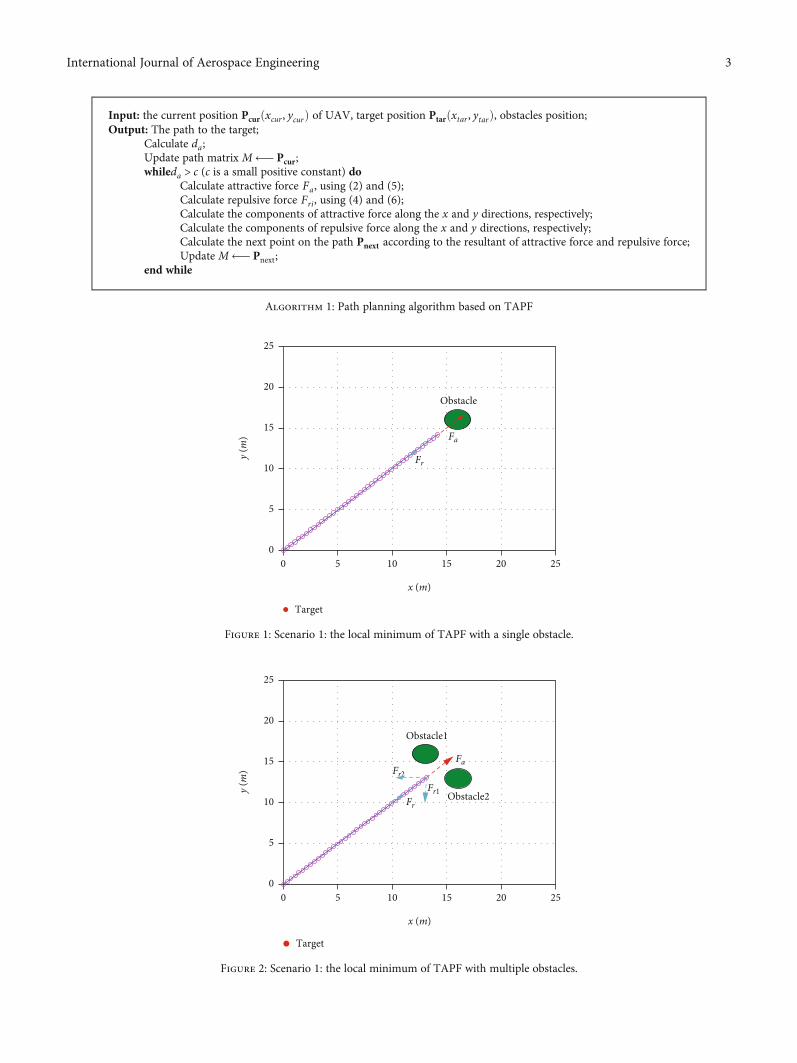
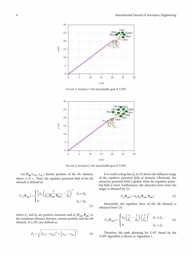
2.3. Unreachable Target. Another shortcoming of TAPF isthat the goal might be inaccessible for UAV, when obstaclesare near the target, as shown in Figures 3 and 4, where Obsi, i = 1,⋯, 8, denotes the ith obstacle. In fact, the attractionof the goal to UAV is gradually decreasing, as the UAVapproaches destination from (5), while the repulsive forceof obstacles to UAV is gradually increasing. Therefore, theUAV fails to plan a path to destination using TAPF.
3. Novel APF Based on Parallel Search
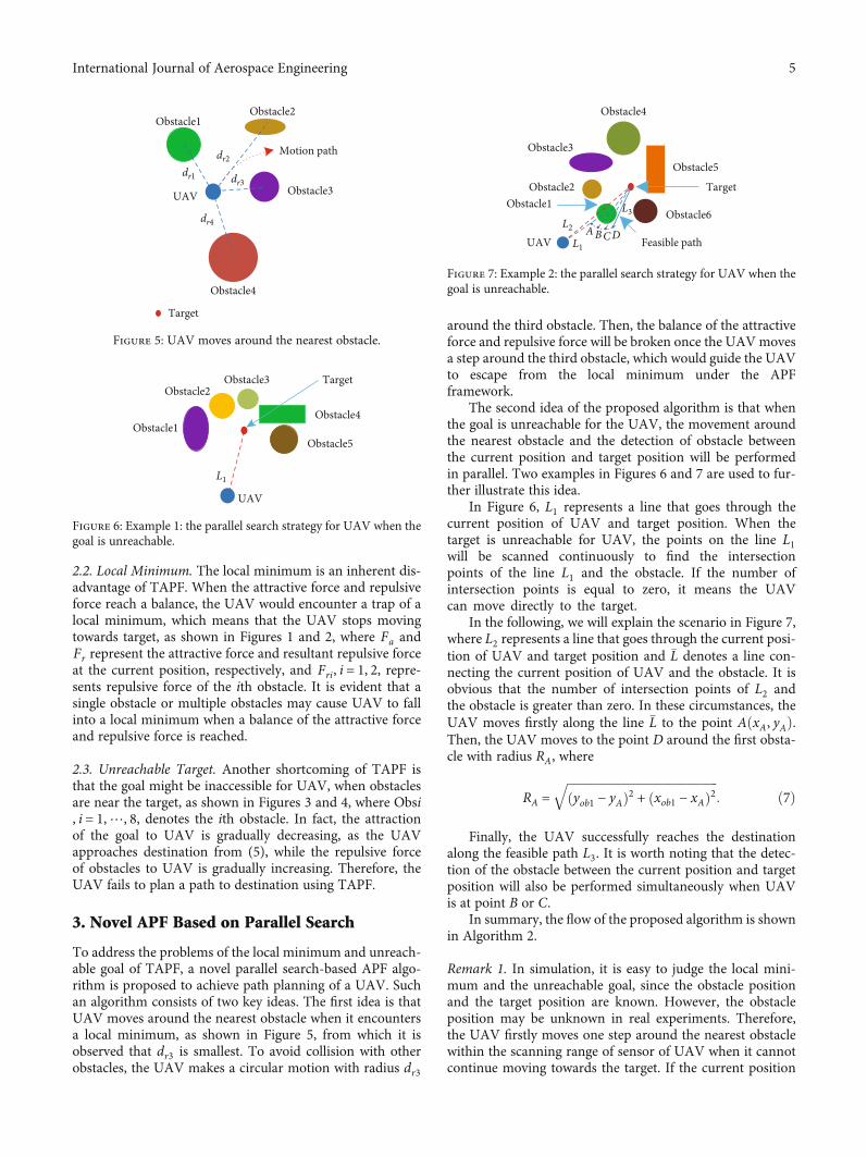
To address the problems of the local minimum and unreach-able goal of TAPF, a novel parallel search-based APF algo-rithm is proposed to achieve path planning of a UAV. Suchan algorithm consists of two key ideas. The first idea is thatUAV moves around the nearest obstacle when it encountersa local minimum, as shown in Figure 5, from which it isobserved that dr3 is smallest. To avoid collision with otherobstacles, the UAV makes a circular motion with radius dr3
around the third obstacle. Then, the balance of the attractiveforce and repulsive force will be broken once the UAVmovesa step around the third obstacle, which would guide the UAVto escape from the local minimum under the APFframework.
The second idea of the proposed algorithm is that whenthe goal is unreachable for the UAV, the movement aroundthe nearest obstacle and the detection of obstacle betweenthe current position and target position will be performedin parallel. Two examples in Figures 6 and 7 are used to fur-ther illustrate this idea.
In Figure 6, L1 represents a line that goes through thecurrent position of UAV and target position. When thetarget is unreachable for UAV, the points on the line L1will be scanned continuously to find the intersectionpoints of the line L1 and the obstacle. If the number ofintersection points is equal to zero, it means the UAVcan move directly to the target.
In the following, we will explain the scenario in Figure 7,where L2 represents a line that goes through the current posi-tion of UAV and target position and �L denotes a line con-necting the current position of UAV and the obstacle. It isobvious that the number of intersection points of L2 andthe obstacle is greater than zero. In these circumstances, theUAV moves firstly along the line �L to the point AðxA, yAÞ.Then, the UAV moves to the point D around the first obsta-cle with radius RA, where
RA =ffiffiffiffiffiffiffiffiffiffiffiffiffiffiffiffiffiffiffiffiffiffiffiffiffiffiffiffiffiffiffiffiffiffiffiffiffiffiffiffiffiffiffiffiffiffiffiffiffiffiyob1 − yAð Þ2 + xob1 − xAð Þ2
q: ð7Þ
Finally, the UAV successfully reaches the destinationalong the feasible path L3. It is worth noting that the detec-tion of the obstacle between the current position and targetposition will also be performed simultaneously when UAVis at point B or C.
In summary, the flow of the proposed algorithm is shownin Algorithm 2.
Remark 1. In simulation, it is easy to judge the local mini-mum and the unreachable goal, since the obstacle positionand the target position are known. However, the obstacleposition may be unknown in real experiments. Therefore,the UAV firstly moves one step around the nearest obstaclewithin the scanning range of sensor of UAV when it cannotcontinue moving towards the target. If the current position
Obstacle1
Obstacle2Obstacle3
Obstacle4
Target
Obstacle5
UAV
L1
Figure 6: Example 1: the parallel search strategy for UAV when thegoal is unreachable.
Feasible path
Obstacle6
Obstacle5
Obstacle4
Obstacle3
Obstacle2Obstacle1
UAVABCD
L1
L3L2
Target
Figure 7: Example 2: the parallel search strategy for UAV when thegoal is unreachable.Obstacle4
Obstacle3
Motion path
Target
Obstacle2Obstacle1
UAV
dr4
dr1
dr2
dr3
Figure 5: UAV moves around the nearest obstacle.
5International Journal of Aerospace Engineering
is a local minimum, the balance of forces will be broken andthe UAV will escape this trap. Otherwise, the UAV moves toan unreachable target.
4. Controller Design Based on NDO
4.1. Mathematical Model of Quadrotor UAV. To track theplanned path in 2D space, only the attitude angles need tobe regulated. Therefore, attitude dynamics of the quadrotorsubject to external disturbances are introduced here.
€ϕ =Jy − Jz� � _θ _φ − Jr _θΩ + LFϕ
Jx+ �dϕ,
€θ = Jz − Jxð Þ _ϕ _φ + Jr _ϕΩ + LFθ
Jy+ �dθ,
€φ =Jx − Jy� �
_ϕ _θ + f Fφ
Jz+ �dφ,
ð8Þ
where ½ϕ, θ, φ� are altitude, roll angle, pitch angle and yawangle of quadrotor, respectively; Fχ, χ = ϕ, θ, φ are the con-trol inputs of the system; L, f , Jr , Jn, n = x, y, z denote the dis-tance from rotor center to mass center, force to momentfactor, inertia of each propeller, inertias of the quadrotoraround x-, y- and z-axes, respectively; andΩ is the differencein angular speed of the rotors on the diagonal of the quadro-tor. The terms �dϕ, �dθ, and �dφ denote the effect of wind on thetranslational and rotational subsystems of the quadrotor in
the form of external disturbances. Compared with brushlessmotor, the propeller of quadrotor is very light; therefore,the terms Jr _θΩ/Jx and Jr _ϕΩ/Jy are ignored here.
4.2. Assumptions. To make the subsequent analysis rigorous,the following assumption is given.
Assumption 1. It is assumed that the disturbances changeslowly, i.e., _dϕ = _dθ = _dφ = 0.
Assumption 2. In the design of controller for the quadrotor,to avoid any singularity, we set −π/2 < ϕ < π/2 and −π/2 < θ< π/2.
4.3. Observer Design. Some of the involved disturbancecomponents in (8) are redefined as dϕ = Jx�dϕ, dθ = Jy�dθ,
and dφ = Jz�dφ. To compensate for external disturbance, aNDO with exponential convergence is proposed. Defineobservation error as
~dχ = dχ − d̂χ, ð9Þ
where d̂χ is the estimate of dχ with χ = ϕ, θ, φ. Consider-ing Assumption 1, the derivative of observation error ~dχin (9) in attitude channel is obtained by
_~dχ = − _̂dχ: ð10Þ
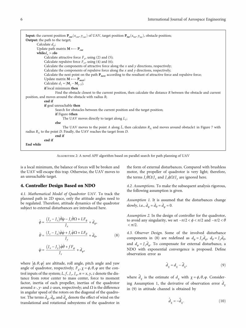
Input: the current position Pcurðxcur, ycurÞ of UAV, target position Ptarðxtar, ytarÞ, obstacle position;Output: the path to the target;
Calculate attractive force Fa, using (2) and (5);Calculate repulsive force Fri, using (4) and (6);Calculate the components of attractive force along the x and y directions, respectively;Calculate the components of repulsive force along the x and y directions, respectively;Calculate the next point on the path Pnext according to the resultant of attractive force and repulsive force;Update matrix M⟵ Pnext;Calculate d1 = jMj −Mj−3j;if local minimum then
Find the obstacle closest to the current position, then calculate the distance R between the obstacle and currentposition, and moves around the obstacle with radius R;
end ifif goal unreachable then
Search for obstacles between the current position and the target position;if Figure 6then
The UAV moves directly to target along L1;else
The UAV moves to the point A along �L, then calculates RA and moves around obstacle1 in Figure 7 withradius RA to the point D. Finally, the UAV reaches the target from D.
end ifend if
End while
Algorithm 2: A novel APF algorithm based on parallel search for path planning of UAV
6 International Journal of Aerospace Engineering
30
30
25
25
20
20
15
Obs1
Obs2
Obs6
Obs5
Obs4Obs3 Target
15
x (m)
y (m
)10
10
5
50
0
Figure 8: Scenario 1: the result of path planning of the proposed algorithm.
30
30
25
25
20Obs1
Obs2
Obs3Obs10
Obs9Obs8
Obs7
Obs6Obs5
Obs4Target
20
15
15
x (m)
y (m
)
10
10
5
50
0
Figure 9: Scenario 2: the result of path planning of the proposed algorithm.
35
35
30
30
25
25
20
20
x (m)
y (m
)
15
15
10
10
Obs1
Obs3
Obs2
Obs4Obs5
Obs8Obs7
Obs6 Target
5
50
0
Figure 10: Scenario 3: the result of path planning of the proposed algorithm in a complex environment.
7International Journal of Aerospace Engineering
Then, the NDO in attitude channel is designed as
_xχ = Pχ Wj − Y j
� �− Pχd̂χ,
d̂χ = xχ + Pχ Jn _χ,ð11Þ
where j = 1, 2, 3, n = x, y, z, W1 = ðJz − JyÞ _θ _φ, Y1 = LU2,
W2 = ðJx − JzÞ _ϕ _φ, Y2 = LU3, W3 = ðJy − JxÞ _ϕ _θ, Y3 = f U4,xχ is an auxiliary variable, and Pχ is a positive gain.
Theorem 2. If Assumption 1 holds and the observer isdesigned as (11), then the observation error ~dz in (9) will expo-nentially converge to zero.
Proof. See Appendix. ☐
Remark 3.Note that d̂χ is not the direct estimates of �dχ in (8)
from (9). If we define d̆χ = d̂χ/ε, ε = Jx, Jy , Jz , then d̆i denote
the estimates of �dχ in (8).
4.4. Controller Design. To address the problem of trackingcontrol in the attitude channel, a backstepping scheme is pro-posed. We define the tracking error of attitude as
eχ = χd − χ, ð12Þ
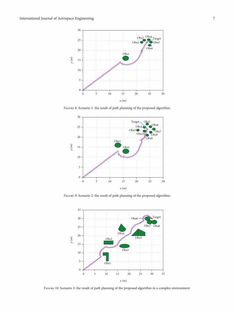
Table 1: The simulation parameters in Figures 8–10.
Parameter Figure 8 Figure 9 Figure 10
Start position (0,0) (0,0) (0,0)
Target position (24,24) (24,24) (32,32)
Obstacle1 position (16,16) (13,16) (10,9)
Obstacle2 position (22,24) (16,13) (11,16)
Obstacle3 position (23,25) (20.5,23.5) (18,14)
Obstacle4 position (24.7,25.2) (23,25) (17,24)
Obstacle5 position (25.5,24) (24,26.5) (24,22)
Obstacle6 position (25,22.5) (25.2,25.2) (28,30)
Obstacle7 position × (26.5,24) (29,28)
Obstacle8 position × (25.3,22.5) (31,28)
Obstacle9 position × (24,21) ×Obstacle10 position × (23,23) ×
25
20
15Obstacle1
Target
10
5
00 5 10 15
x (m)
y (m
)
20 25
Obstacle111
Targeggggggggggggggg
O
RRTBUG2Proposed
BUG1
Figure 12: Scenario 2: the result of path planning of the fouralgorithms with an obstacle.
40
35
30
25
20
15
10Obstacle1
Obstacle2Obstacle3
Obstacle4Obstacle5
Target
5
04035302520
x (m)
y (m
)
151050
Obstacle1
Obstacle2Obstacle3
Obstacle4Obstacle5
O 1
bbb
ss
RRTBUG2Proposed
BUG1
Figure 13: Scenario 1: the result of path planning of the fouralgorithms with multiple obstacles.
25
20
15
15
Obstacle1
Target
x (m)
20 25
10
y (m
)
10
5
50
0
Obstacle1
Targetetetgetgegetetttgeteeetgetetetettggggggggg
O
RRTBUG2Proposed
BUG1
Figure 11: Scenario 1: the result of path planning of the fouralgorithms with an obstacle.
8 International Journal of Aerospace Engineering
where χd is the desired altitude signal. Then, the attitude con-troller is designed as
Fχ = Rj +Gj cχ1 _eχ + €χd + eχ + cχ2eχ1� �
+Qj, ð13Þ
where R1 = ððJz − JyÞ/LÞ _θ _φ, G1 = Jx/L, Q1 = d̂ϕ/L, R2 = ððJx− JzÞ/LÞ _ϕ _φ, G2 = Jy/L, Q3 = d̂θ/L, R3 = ððJy − JxÞ/LÞ _ϕ _θ, G3= Jz/f , Q3 = d̂φ/f , cχ1, cχ2 > λχ/2 with λχ being a positiveconstant, and
eχ1 = − _χ + cχ1eχ + _χd: ð14Þ
Theorem 4. Under Assumption 1 and Assumption 2, for thealtitude dynamics in (8), if the control input Fχ is designedas (13), then the tracking error for desired attitude is guaran-teed to converge to zero exponentially, i.e., eχ ⟶ 0 as t⟶∞.
Proof. See Appendix. ☐
5. Simulation
5.1. Comparison with TAPF. The simulation parametersincluding the start position, target position, and obstaclepositions in Figures 8–10 are listed in Table 1. To demon-strate the effectiveness of the proposed path planning frame-work to deal with the traps of local minimum andunreachable goal of TAPF in Figures 1–4, simulations arecarried out, as shown in Figures 8 and 9, where we canobserve that the UAV can plan a feasible path to the destina-tion with obstacle avoidance. Furthermore, the proposedalgorithm is verified in complex environments with multipleobstacles in Figure 10.
5.2. Comparison with BUG1, BUG2, and RRT. Consideringthe characteristics of the proposed algorithm, BUG1,
RRTBUG2Proposed
BUG1
40
40
35
35
30
30
25
25
20
20
x (m)
y (m
)
15
15
10
Obstacle1Obstacle2
Obstacle4
Obstacle3
Obstacle5
Obstacle6 Obstacle7
Target
10
5
50
0
Figure 14: Scenario 2: the result of path planning of the four algorithms with multiple obstacles.
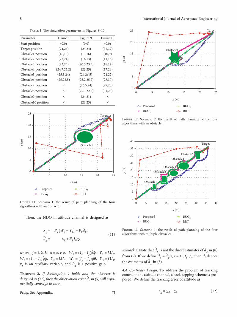
Table 2: The simulation parameters in Figures 11–14.
Parameter Figure 11 Figure 12 Figure 13 Figure 14
Start position (0,0) (0,0) (0,0) (0,0)
Target position (24,24) (24,24) (36,36) (36,36)
Obstacle1 position (16,15) (12,13) (9,9) (9,10)
Obstacle2 position × × (14,14) (14,16)
Obstacle3 position × × (19,18) (20,10)
Obstacle4 position × × (24,23) (20,20)
Obstacle5 position × × (31,30) (29,17)
Obstacle6 position × × × (28,28)
Obstacle7 position × × × (35,34)Table 4: Path length of the four algorithms in Figures 11–14.
Algorithm Figure 11 Figure 12 Figure 13 Figure 14
Proposed 35.8800m 35.5200m 56.1371m 56.6288m
BUG1 37.1662m 38.5924m 62.7243m 65.8486m
BUG2 36.3676m 37.3622m 64.2180m 63.2446m
RRT 56.2966m 44.4007m 66.2756m 91.0735m
Table 3: Time consumption of the four algorithms in Figures 11–14.
Algorithm Figure 11 Figure 12 Figure 13 Figure 14
Proposed 0.0567 s 0.0554 s 0.0748 s 0.0947 s
BUG1 0.0829 s 0.0736 s 0.1292 s 0.1419 s
BUG2 0.0701 s 0.0714 s 0.1210 s 0.1260 s
RRT 0.7150 s 0.2022 s 1.1637 s 0.5662 S
9International Journal of Aerospace Engineering
BUG2, and RRT, and to fairly compare their abilities ofpath planning, the obstacles of different shapes are placedaround the line connecting the start point and the targetpoint.
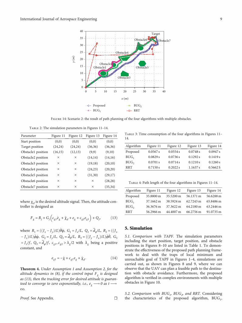
The simulation parameters including the start position,target position, and obstacle positions in Figures 11–14 areshown in Table 2. Furthermore, the comparisons with thethree path planning algorithms, namely, BUG1, BUG2, andRRT, are presented in Figures 11–14. Figures 11 and 12show the results of path planning of UAV with a singleobstacle, while the results of path planning of UAV withmultiple obstacles are shown in Figures 13 and 14. Fromthe results, the feasible path to the target with obstacleavoidance can be obtained when the proposed algorithm,BUG1, BUG2, and RRT are applied to path planning ofthe UAV, respectively. Table 3 shows the time consump-tion of the four algorithms. It is obvious that in eitherthe environment with a single obstacle or with multipleobstacles, the time consumption of the proposed algorithmis the least. The path length in Figures 11–14 are listed inTable 4, from which we find that compared with pathsgenerated by BUG1, BUG2, and RRT, a shorter path isobtained using the proposed algorithm. For the environ-ment with a single obstacle, the shape of obstacle has agreater effect on the length of path provided by BUG1and BUG2. Meanwhile, RRT has the worst performance
in terms of time consumption and path length. Also, theUAV cannot reach the target accurately when RRT isapplied to the UAV.
Overall, compared with BUG1, BUG2, and RRT, the pro-posed algorithm has advantages in time consumption andpath length, which means that less time and energy arerequired to reach the target for the UAV.
5.3. Trajectory Tracking. The physical parameters of quadro-tor are set as follows: L = 0:4m, Jx = 0:16 kgm2, Jy = 0:16kgm2, Jz = 0:32 kgm2, and f = 0:05m. The initial attitude ofthe quadrotor is set as 0rad. Furthermore, to follow theplanned path, the desired attitude angles need to beaddressed. Figure 11 is used as an example here, whosedesired attitude states are calculated as follows: dϕ = 0, dθ1 =1, dθ2 = 0, dφ1 = 0:785, dφ2 = 1:415, dφ3 = 2:597, dφ4 = 1:537,dφ5 = 1:865, dφ6 = 1:617, dφ7 = 1:514, dφ8 = 1:399, dφ9 =1:288, dφ10 = 1:181, dφ11 = 1:011, dφ12 = 0:985, dφ13 = 0:813,dφ14 = 0:78, dφ15 = 0:737, dφ16 = 0:669, dφ17 = 0:607, dφ18 =0:552, dφ19 = 0:506, and dφ20 = 0:47. It should be noted that(1) the yaw angle is used to adjust the forward directionof the quadrotor, and the pitch angle is used to controlthe forward speed of the quadrotor, while the roll angle isrequired to maintain at 0rad and (2) when the yaw angleis trying to maintain one of the above states, a desired pitch
4
2
0
–20 5 10 15 20
Time (s)
25 30 35
d𝜙, d
𝜙 (r
ad/s
2 )2
1
0
–10 5 10 15 20
Time (s)
25 30 35
d𝜃, d
𝜃 (r
ad/s
2 )
1.5
1
0
–0.50 5 10 15 20
Time (s)
25 30 35
dφ, d
φ (r
ad/s
2 )
0.5
DisturbanceObservation
Figure 15: Estimations of external disturbances.
10 International Journal of Aerospace Engineering
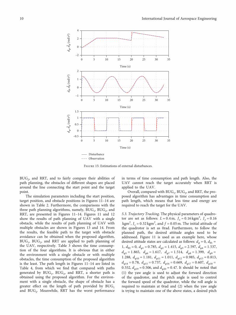
angle of 0:1rad will be tracked and when the yaw angle isswitched between the two states, the desired pitch angle isset as 0rad. In addition, the disturbances in attitude chan-nels are given as
dϕ =
0:4t − 0:2, 0 ≤ t < 6,2:2, 6 ≤ t < 14,−0:1t + 3:6, 14 ≤ t < 20,−0:t + 5:6, 20 ≤ t < 33,
8>>>>><>>>>>:
ð15Þ
dθ = cos π
6 t� �
+ 0:4, ð16Þ
dφ =1, 0 ≤ t < 5 or 10 ≤ t < 15⋯,0, 5 ≤ t < 10 or 15 ≤ t ≤ 20⋯:
(ð17Þ
To verify the effectiveness of the proposed NDO, thetime-varying disturbance with different frequencies areinjected into the quadrotor system. The estimations ofexternal disturbances are shown in Figure 15, where wecan see that the disturbances (15), (16), (17) can be esti-mated, even if the derivatives of the disturbances areassumed to be 0 in the design of the disturbance observer.
However, the disturbance estimations of the pitch and yawchannels have small fluctuations.
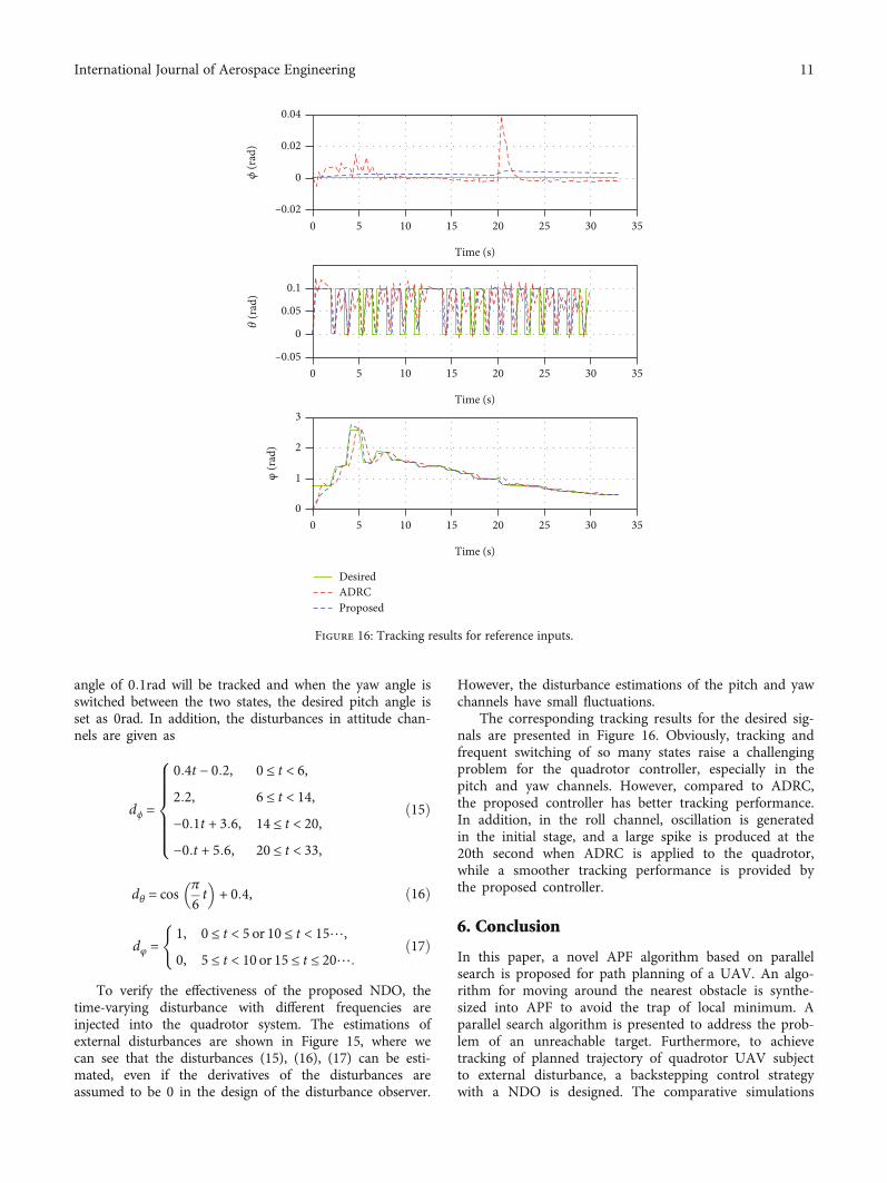
The corresponding tracking results for the desired sig-nals are presented in Figure 16. Obviously, tracking andfrequent switching of so many states raise a challengingproblem for the quadrotor controller, especially in thepitch and yaw channels. However, compared to ADRC,the proposed controller has better tracking performance.In addition, in the roll channel, oscillation is generatedin the initial stage, and a large spike is produced at the20th second when ADRC is applied to the quadrotor,while a smoother tracking performance is provided bythe proposed controller.
6. Conclusion
In this paper, a novel APF algorithm based on parallelsearch is proposed for path planning of a UAV. An algo-rithm for moving around the nearest obstacle is synthe-sized into APF to avoid the trap of local minimum. Aparallel search algorithm is presented to address the prob-lem of an unreachable target. Furthermore, to achievetracking of planned trajectory of quadrotor UAV subjectto external disturbance, a backstepping control strategywith a NDO is designed. The comparative simulations
0.04
0.02
–0.02
0𝜙 (r
ad)
𝜃 (r
ad)
φ (r
ad)
0
0.1
0.05
–0.05
0
5 10 15
Time (s)
Time (s)
Time (s)
20 25 30 35
0
3
2
1
5 10 15 20 25 30 35
00
5 10 15 20 25 30 35
DesiredADRCProposed
Figure 16: Tracking results for reference inputs.
11International Journal of Aerospace Engineering
are performed to verify the effectiveness of the proposedpath planning algorithm and the proposed controller.
Appendix
A. Proof of Theorem 2
Proof. From the second equation in (11), one has
_̂dχ = _xχ + Pχ Jn€χ: ðA:1Þ
Substituting the first equation to (A.1) yields
_̂dχ = Pχ Wj − Y j + Jn€χ� �
− Pχd̂χ: ðA:2Þ
Considering the relationship dχ = Jn�dχ and applying(8)–(17) (A.1), (A.2), we have
_̂dχ = Pχ dχ − d̂χ� �
= Pχ~dχ: ðA:3Þ
Combining (10), the dynamic equation of observationerror is obtained:
_~dχ + Pχ~dχ = 0: ðA:4Þ
Solving (A.4), we get
~dχ tð Þ = ~dχ t0ð Þe−Pχt , ðA:5Þ
where ~dχðt0Þ is the initial value of the observation error. (A.5)indicates that the observation error ~dχ will exponentially
converge to zero as t⟶∞, i.e., d̂χ will exponentially con-verge to dχ as t⟶∞ under Assumption 1.
This completes the proof. ☐
B. Proof of Theorem 4
Proof. The whole proof is divided into two steps.Step 1. We define a Lyapunov function candidate
Vχ1 =12 Jne
2χ: ðB:1Þ
The time derivative of Vχ1 is
_Vχ1 = Jneχ _eχ: ðB:2Þ
Substituting (12) and (14) to (17), (A.1)–(B.2), it isobtained that
Substituting the attitude controller (13) into (B.8) yields
_Vz = −Jncχ1e2χ + Jneχeχ1 + Jneχ1 −eχ − cχ2eχ1 +
1Jn
dχ − d̂χ� �� �
= −Jncχ1e2χ − Jncχ2e
2χ1 + eχ1 dχ − d̂χ
� �:
ðB:8Þ
The term dχ − d̂χ will vanish from Theorem 2 as t⟶∞. Hence, according to (B.1), (B.4) and the relationship cχ1,cχ2 ≥ λχ/2, (B.8) is further derived as
_Vχ = −Jncχ1e2χ − Jncχ2e
2χ1
= −λχVχ − cχ1 −λχ2
� �Jne
2χ − cχ2 −
λχ2
� �Jne
2χ1≤−λχVχ:
ðB:9Þ
Solving (B.9), it is obtained
Vχ tð Þ ≤Vχ 0ð Þe−λχt , ðB:10Þ
where Vχð0Þ is the initial value of VχðtÞ. From (B.10), it isconcluded that eχ will exponentially converge to zero as t⟶∞.
This completes the proof. ☐
Data Availability
The data used to support this study are included within thearticle.
Conflicts of Interest
The authors declare that they have no conflicts of interest.
12 International Journal of Aerospace Engineering
Acknowledgments
The work was supported by the National Natural ScienceFoundation of China under Grants 61773323, U1934221,and 61733015.
References
[1] F. Outay, H. A. Mengash, and M. Adnan, “Applications ofunmanned aerial vehicle (UAV) in road safety, traffic andhighway infrastructure management: recent advances andchallenges,” Transportation Research Part A, vol. 141,pp. 116–129, 2020.
[2] B. D. Song, K. Park, and J. Kim, “Persistent uav delivery logis-tics: Milp formulation and efficient heuristic,” Computers andIndustrial Engineering, vol. 120, pp. 418–428, 2018.
[3] A. Navarro, M. Young, B. Allan, P. Carnell, P. Macreadie, andD. Ierodiaconou, “The application of unmanned aerial vehicles(UAVs) to estimate above-ground biomass of mangrove eco-systems,” Remote Sensing of Environment, vol. 242, article111747, 2020.
[4] G. M. Hoffmann, H. Huang, S. L. Waslander, and C. J. Tomlin,“Precision flight control for a multi-vehicle quadrotor helicop-ter testbed,” Control Engineering Practice, vol. 19, no. 9,pp. 1023–1036, 2011.
[5] T. Huang, D. Huang, and D. Luo, “Attitude tracking for aquadrotor UAV based on fuzzy PID controller,” in 5th Inter-national Conference on Information, Cybernetics, and Compu-tational Social Systems, pp. 1–6, Zhengjiang, China, 2018.
[6] K. Chang, Y. Xia, K. Huang, and D. Ma, “Obstacle avoidanceand active disturbance rejection control for a quadrotor,” Neu-rocomputing, vol. 190, pp. 60–69, 2016.
[7] Y. Zhang, Z. Chen, X. Zhang, Q. Sun, and M. Sun, “A novelcontrol scheme for quadrotor UAV based upon active distur-bance rejection control,” Aerospace Science and Technology,vol. 79, pp. 601–609, 2018.
[8] T. Huang, D. Huang, Z. Wang, X. Dai, and A. Shah, “Genericadaptive sliding mode control for a quadrotor UAV systemsubject to severe parametric uncertainties and fully unknownexternal disturbance,” International Journal of Control, Auto-mation and Systems, vol. 19, no. 2, pp. 698–711, 2021.
[9] H. Ríos, R. Falcón, O. A. González, and A. Dzul, “Continuoussliding-mode control strategies for quadrotor robust tracking:real-time application,” IEEE Transactions on Industrial Elec-tronics, vol. 66, no. 2, pp. 1264–1272, 2019.
[10] B. Tian, J. Cui, H. Lu, Z. Zuo, and Q. Zong, “Adaptive finite-time attitude tracking of quadrotors with experiments andcomparisons,” IEEE Transactions on Industrial Electronics,vol. 66, no. 12, pp. 9428–9438, 2019.
[11] X. Lyu, J. Zhou, H. Gu, Z. Li, S. Shen, and F. Zhang, “Distur-bance observer based hovering control of quadrotor tail-sitter VTOL UAVs using H∞ synthesis,” IEEE Robotics andAutomation Letters, vol. 3, no. 4, pp. 2910–2917, 2018.
[12] A. Poultney, C. Kennedy, G. Clayton, and H. Ashrafiuon,“Robust tracking control of quadrotors based on differentialflatness: simulations and experiments,” IEEE/ASME Transac-tions on Mechatronics, vol. 23, no. 3, pp. 1126–1137, 2018.
[13] N. Koksal, M. Jalalmaab, and B. Fidan, “Adaptive linear qua-dratic attitude tracking control of a quadrotor UAV based onIMU sensor data fusion,” Sensors, vol. 19, no. 1, pp. 46–123,2019.
[14] F. Chen, W. Lei, K. Zhang, G. Tao, and B. Jiang, “A novel non-linear resilient control for a quadrotor UAV via backsteppingcontrol and nonlinear disturbance observer,” NonlinearDynamics, vol. 85, no. 2, pp. 1281–1295, 2016.
[15] C. Xu, H. Duan, and F. Liu, “Chaotic artificial bee colonyapproach to uninhabited combat air vehicle (UCAV) pathplanning,” Aerospace Science and Technology, vol. 14, no. 8,pp. 535–541, 2010.
[16] C. Lin, G. Han, X. Qi, J. du, T. Xu, and M. Martinez-Garcia,“Energy-optimal data collection for unmanned aerial vehicle-aided industrial wireless sensor network-based agriculturalmonitoring system: a clustering compressed samplingapproach,” IEEE Transactions on Industrial Informatics,vol. 17, no. 6, pp. 4411–4420, 2021.
[17] X. Wu, W. Bai, Y. Xie, X. Sun, C. Deng, and H. Cui, “A hybridalgorithm of particle swarm optimization, metropolis criterionand RTS smoother for path planning of UAVs,” Applied SoftComputing, vol. 73, pp. 735–747, 2018.
[18] N. Bolourian and A. Hammad, “Lidar-equipped UAV pathplanning considering potential locations of defects for bridgeinspection,” Automation in Construction, vol. 117, article103250, 2020.
[19] V. Roberge, M. Tarbouchi, and G. Labonté, “Comparison ofparallel genetic algorithm and particle swarm optimizationfor real-time UAV path planning,” IEEE Transactions onIndustrial Informatics, vol. 9, no. 1, pp. 132–141, 2013.
[20] C. Xu, M. Xu, and C. Yin, “Optimized multi-UAV cooperativepath planning under the complex confrontation environ-ment,” Computer Communications, vol. 162, pp. 196–203,2020.
[21] C. Qu, W. Gai, J. Zhang, and M. Zhong, “A novel hybrid greywolf optimizer algorithm for unmanned aerial vehicle (UAV)path planning,” Knowledge-Based Systems, vol. 194, article105530, 2020.
[22] K. Li, F. Ge, Y. Han, Y. Wang, and W. Xu, “Path planning ofmultiple UAVs with online changing tasks by an ORPFOAalgorithm,” Engineering Applications of Artificial Intelligence,vol. 94, article 103807, 2020.
[23] C. Chen, D. Pi, and Y. Xu, “Neighborhood global learningbased flower pollination algorithm and its application tounmanned aerial vehicle path planning,” Expert Systems withApplications, vol. 170, article 114505, 2021.
[24] P. Yang, K. Tang, J. A. Lozano, and X. Cao, “Path planning forsingle unmanned aerial vehicle by separately evolving way-points,” IEEE Transactions on Robotics, vol. 31, no. 5,pp. 1130–1146, 2015.
[25] X. Yu, C. Li, and J. Zhou, “A constrained differential evolutionalgorithm to solve UAV path planning in disaster scenarios,”Knowledge-Based Systems, vol. 204, article 106209, 2020.
[26] J. Park and H. J. Kim, “Online trajectory planning for multiplequadrotors in dynamic environments using relative safe flightcorridor,” IEEE Robotics and Automation Letters, vol. 6, no. 2,pp. 659–666, 2021.
[27] S. H. Kim, G. E. G. Padilla, K. J. Kim, and K. H. Yu, “Flightpath planning for a solar powered uav in wind fields usingdirect collocation,” IEEE Transactions on Aerospace and Elec-tronic Systems, vol. 56, no. 2, pp. 1094–1105, 2020.
[28] C. Yin, Z. Xiao, X. Cao, X. Xi, P. Yang, and D.Wu, “Offline andonline search: UAV multi-objective path planning underdynamic urban environment,” IEEE Internet of Things Journal,vol. 5, no. 2, pp. 546–558, 2018.
13International Journal of Aerospace Engineering
[29] Y. Liu, Q. Wang, H. Hu, and Y. He, “A novel real-time movingtarget tracking and path planning system for a quadrotor UAVin unknown unstructured outdoor scenes,” IEEE Transactionson Systems Man and Cybernetics Systems, vol. 49, no. 11,pp. 2362–2372, 2019.
[30] C. Liu, S. Zhang, and A. Akbar, “Ground feature oriented pathplanning for unmanned aerial vehicle mapping,” IEEE Journalof Selected Topics in Applied Earth Observations and RemoteSensing, vol. 12, no. 4, pp. 1175–1187, 2019.
[31] H. Wang, J. Wang, G. Ding, J. Chen, F. Gao, and Z. Han,“Completion time minimization with path planning forfixed-wing UAV communications,” IEEE Transactions onWireless Communications, vol. 18, no. 7, pp. 3485–3499, 2019.
[32] Y. Cai, Q. Xi, X. Xing, H. Gui, and Q. Liu, “Path planning forUAV tracking target based on improved a-star algorithm,” inInternational Conference on Industrial Artificial Intelligence,pp. 1–6, Shenyang, China, 2019.
[33] X. Chen, G. Y. Li, and X. M. Chen, “Path planning and coop-erative control for multiple UAVs based on consistency theoryand Voronoi diagram,” in 2017 29th Chinese Control AndDecision Conference (CCDC), pp. 881–886, Chongqing, China,2017.
[34] M. Li, Q. Sun, and M. Zhu, “UAV 3-dimension flight pathplanning based on improved rapidly-exploring random tree,”in 2019 Chinese Control And Decision Conference (CCDC),pp. 921–925, Nanchang, China, 2019.
[35] B. Kovács, G. Szayer, F. Tajti, M. Burdelis, and P. Korondi, “Anovel potential field method for path planning of mobilerobots by adapting animal motion attributes,” Robotics andAutonomous Systems, vol. 82, pp. 24–34, 2016.
[36] U. Orozco-Rosas, O. Montiel, and R. Sepúlveda, “Mobile robotpath planning using membrane evolutionary artificial poten-tial field,” Applied Soft Computing, vol. 77, pp. 236–251, 2019.
[37] Z. Huang, D. Chu, C. Wu, and Y. He, “Path planning andcooperative control for automated vehicle platoon usinghybrid automata,” IEEE Transactions on Intelligent Transpor-tation Systems, vol. 20, no. 3, pp. 959–974, 2019.
[38] J. Liu, C. Xu, Z.Wu, and Y. F. Chen, “Intelligent rebar layout inRC building frames using artificial potential field,” Automa-tion in Construction, vol. 114, article 103172, 2020.
[39] J. J. Kandathil, R. Mathew, and S. S. Hiremath, “Developmentand analysis of a novel obstacle avoidance strategy for a multi-robot system inspired by the bug-1 algorithm,” Simulation:Transactions of The Society for Modeling and Simulation Inter-national, vol. 96, no. 10, pp. 807–824, 2020.
[40] S. Yang, X. Wang, Y. Wen, J. Wang, and S. Li, “A new intelli-gent trajectory planning algorithm based on bug2 algorithm:-bridge algorithm,” in International Conference on Roboticsand Biomimetics, pp. 2079–2084, Dali, China, 2019.