Patterned optical anisotropy in woven conjugated polymer systems C. M€ uller, 1,a) M. Garriga, 2 and M. Campoy-Quiles 2 1 Department of Chemical and Biological Engineering/Polymer Technology, Chalmers University of Technology, 41296 G€ oteborg, Sweden 2 Institut de Cie `ncia de Materials de Barcelona (ICMAB-CSIC), Campus de la UAB, E-08193 Bellaterra, Spain (Received 11 August 2012; accepted 11 October 2012; published online 25 October 2012) Weaving of highly oriented conjugated polymer/polyethylene tapes is demonstrated to permit the generation of concealed patterns that can be detected under appropriate polarized light illumination. This is achieved by exploiting the fact that the amount of transmitted light varies with the superposition sequence of semi-transparent objects that feature a high degree of linear birefringence as well as linear dichroism. An analysis based on M€ uller calculus provides a theoretical description of the observed optical behavior. V C 2012 American Institute of Physics. [http://dx.doi.org/10.1063/1.4764518] Anisotropic optical characteristics of conjugated poly- mers have been exploited in a broad variety of applications, including polarized-light emitting diodes 1–4 and optical filters, such as electrochromic, 5 photoluminescent 6–8 as well as infra- red polarizers, 9 for use in counterfeiting products, 10 liquid crystal displays, 11 and the like. An efficient method to realize such anisotropic optical features is based on unidirectional alignment of the conjugated species in a polymeric host by tensile drawing. 6–19 However, creation of patterned features, which are a prerequisite for the realization of more complex articles, has so far been challenging when employing this pro- cedure. Principally, this is due to the required mechanical deformation step that prevents the use of regular lithography or printing techniques. Indeed, it seems that selective photo- bleaching of a photoluminescent moiety embedded in an ultra-high molecular-weight polyethylene (UHMW-PE) ma- trix is one of the only methods that has been advanced, which permits fabrication of well-defined structures and images in discrete tensile-oriented polymer films. 16 We explored, therefore, other options to create optical patterns, focusing on superimposing highly anisotropic mate- rials that feature both linear birefringence as well as linear dichroism, produced by standard tensile deformation of a suitable guest/host polymer system. We demonstrate that this approach is compatible with straightforward weaving schemes widely utilized in textile manufacturing. 20 This is illustrated by the realization of optically concealed images in apparently uniform fabrics (when observed in unpolarized light), which can be detected only under appropriate polarized-light illumination. We selected blends of regio-regular poly(3-hexylthio- phene) (P3HT) and UHMW-PE for the creation of such optically anisotropic systems. P3HT is one of the most extensively studied conjugated polymers, absorbing at wave- lengths, k, between 400 and 650 nm in the solid state, 21–25 whilst UHMW-PE has previously been reported to facilitate uniaxial orientation of high aspect-ratio guest-species by tensile drawing. 6–9,11,13–16 Samples were prepared by first dissolving 0.01 g l 1 P3HT (purchased from Sigma Aldrich; M w 48 kg mol 1 ; regio-regularity > 90%) and 1gl 1 UHMW-PE (obtained from DSM; M w 6100 kg mol 1 ) in decalin at 130 C followed by casting at ambient. Dried 1:99 P3HT/UHMW-PE films were tensile drawn to 30–40 times their initial length at 120 C to produce oriented tapes of thickness d 10 lm. Highly efficient alignment of the ma- trix polymer and thus of the conjugated host species in the drawing direction was achieved, giving rise to high levels of linear birefringence (retardance) and linear dichroism (attenuation), respectively. The linear birefringence is read- ily apparent from a series of cross-polarized optical micro- graphs in Fig. 1(a). In addition, linear dichroism occurs at wavelengths, at which the P3HT moiety is absorbing, as evi- denced by polarized UV-Vis absorbance spectra (recorded with a Perkin Elmer Lambda 900 spectrophotometer) as well as polarized optical micrographs in Fig. 1(b). As a matter of fact, a dark purple color with a maximum absorbance at 550 nm was found for such aligned tapes when back- illuminated with light polarized parallel to the drawing direc- tion, whereas perpendicularly polarized light resulted in a pale pink appearance with a blue-shifted maximum absorb- ance around 500 nm. There exists a vast library of fabric patterns that can be generated by weaving the here discussed P3HT/UHMW-PE tapes. Each weave can be considered as an individual ele- ment of such a system, comprised of at least two tapes cross- ing each other at angle u, where u is the relative orientation between the drawing directions of the individual tapes. For instance, in case of a plain weave, which features a basket- case like alternating weaving pattern, 20 the relative orienta- tion of tapes that make up adjacent segments, here labeled A and B, is equivalent to two pairs of tapes with opposite plait- ing sequence so that u A ¼u B . Similar to a single tape, weaves are likely to be of featureless appearance when observed in plain, unpolarized light. However, when placed between a pair of crossed polarizers as outlined in Fig. 2(a), the transmitted light intensity will strongly depend on both the orientation of the weave with respect to the polarizer sys- tem as well as u. Since such a train of optical elements behaves in a non-commutative manner, we can expect their appearance to vary for different sequences of the two tapes. a) e-mail: [email protected]. 0003-6951/2012/101(17)/171907/5/$30.00 V C 2012 American Institute of Physics 101, 171907-1 APPLIED PHYSICS LETTERS 101, 171907 (2012)
Transcript
Patterned optical anisotropy in woven conjugated polymer systems
C. M€uller,1,a) M. Garriga,2 and M. Campoy-Quiles2
1Department of Chemical and Biological Engineering/Polymer Technology,Chalmers University of Technology, 41296 G€oteborg, Sweden2Institut de Ciencia de Materials de Barcelona (ICMAB-CSIC), Campus de la UAB, E-08193Bellaterra, Spain
(Received 11 August 2012; accepted 11 October 2012; published online 25 October 2012)
Weaving of highly oriented conjugated polymer/polyethylene tapes is demonstrated to permit the
generation of concealed patterns that can be detected under appropriate polarized light
illumination. This is achieved by exploiting the fact that the amount of transmitted light varies with
the superposition sequence of semi-transparent objects that feature a high degree of linear
birefringence as well as linear dichroism. An analysis based on M€uller calculus provides a
theoretical description of the observed optical behavior. VC 2012 American Institute of Physics.
[http://dx.doi.org/10.1063/1.4764518]
Anisotropic optical characteristics of conjugated poly-
mers have been exploited in a broad variety of applications,
including polarized-light emitting diodes1–4 and optical filters,
such as electrochromic,5 photoluminescent6–8 as well as infra-
red polarizers,9 for use in counterfeiting products,10 liquid
crystal displays,11 and the like. An efficient method to realize
such anisotropic optical features is based on unidirectional
alignment of the conjugated species in a polymeric host by
tensile drawing.6–19 However, creation of patterned features,
which are a prerequisite for the realization of more complex
articles, has so far been challenging when employing this pro-
cedure. Principally, this is due to the required mechanical
deformation step that prevents the use of regular lithography
or printing techniques. Indeed, it seems that selective photo-
bleaching of a photoluminescent moiety embedded in an
polarized photographs of tapes (orientation of crossed polarizers as indi-
cated). Note the high level of birefringence (variation in light intensity) as
well as dichroism (change in color) of this system. (b) UV-Vis absorbance
spectra (top panel) and photographs (bottom panel) of a tape back-
illuminated with light polarized parallel (solid line) and perpendicular
(dashed line) to the drawing direction (orientation of polarizer as indicated).
171907-2 M€uller, Garriga, and Campoy-Quiles Appl. Phys. Lett. 101, 171907 (2012)
well as linearly dichroic element, e.g., a stretched P3HT/
UHMW-PE tape, oriented at angle h30
Mpolarizer ¼1
2�
1 c2a s2a 0
c2a c22a s2ac2a 0
s2a s2ac2a s22a 0
0 0 0 0
2664
3775; (2)
Mtape
¼ e~A �
Cd0 �c2hSd0 �s2hSd0 0
�c2hSd0 c22hCd0 þs2
2hcd s2hc2hðCd0 �cdÞ �s2hsd
�s2hSd0 s2hc2hðCd0 �cdÞ s22hCd0 þc2
2hcd c2hsd
0 s2hsd �c2hsd cd
26664
37775;
(3)
where s2a ¼ sin 2a, c2a ¼ cos 2a, s2h ¼ sin 2h, c2h ¼ cos 2h,
sd ¼ sin d, cd ¼ cos d, Sd0 ¼ sinh d0, and Cd0 ¼ cosh d0.31 The
tape features a mean absorbance, ~A
~A ¼ ln10
2� ðAx þ AyÞ; (4)
where Ax and Ay are the absorbance parallel and perpendicu-
lar to the orientation direction of the tape, a retardance, d
d ¼ 2p � Dn � dk
; (5)
where Dn is the birefringence and d the thickness of the tape,
and an attenuation, d032
d0 ¼ ln10
2� ðAx � AyÞ: (6)
The linear dichroism of P3HT/UHMW-PE tapes could
be conveniently estimated using polarized UV-Vis absorb-
ance spectroscopy. For instance, at 550 nm we observe a
maximum absorbance, Ax,550� 0.88, parallel to the orienta-
tion direction of the tape and a much reduced perpendicular
absorbance, Ay,550� 0.12 (cf. Fig. 1(b)). Thus, using Eqs. (4)
and (6) we obtain ~A550� 1.151 and d0
550� 0.875.
The linear birefringence of highly oriented polyethy-
lenes is insensitive to the exact draw ratio and thus we esti-
mate a value of Dn� 0.058 according to Ref. 33.26 We
assume a largely wavelength-independent birefringence and
negligible contribution from the P3HT guest species and
employ Eq. (5) to obtain a retardance d550� 6.626 at 550 nm
for a thickness d¼ 10 lm.
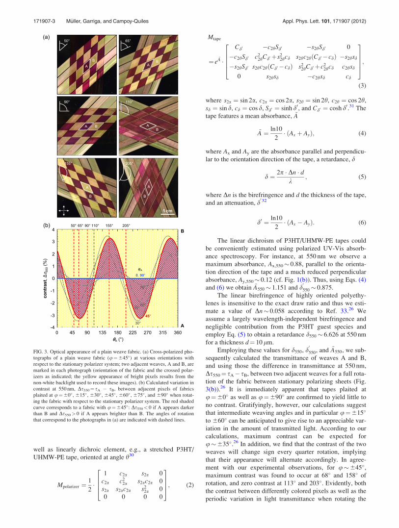
Employing these values for d550, d0
550, and ~A550, we sub-
sequently calculated the transmittance of weaves A and B,
and using those the difference in transmittance at 550 nm,
Ds550¼ sA� sB, between two adjacent weaves for a full rota-
tion of the fabric between stationary polarizing sheets (Fig.
3(b)).26 It is immediately apparent that tapes plaited at
u¼60� as well as u¼690� are confirmed to yield little to
no contrast. Gratifyingly, however, our calculations suggest
that intermediate weaving angles and in particular u¼615�
to 660� can be anticipated to give rise to an appreciable var-
iation in the amount of transmitted light. According to our
calculations, maximum contrast can be expected for
u�635�.26 In addition, we find that the contrast of the two
weaves will change sign every quarter rotation, implying
that their appearance will alternate accordingly. In agree-
ment with our experimental observations, for u�645�,maximum contrast was found to occur at 68� and 158� of
rotation, and zero contrast at 113� and 203�. Evidently, both
the contrast between differently colored pixels as well as the
periodic variation in light transmittance when rotating the
FIG. 3. Optical appearance of a plain weave fabric. (a) Cross-polarized pho-
tographs of a plain weave fabric (u¼645�) at various orientations with
respect to the stationary polarizer system; two adjacent weaves, A and B, are
marked in each photograph (orientation of the fabric and the crossed polar-
izers as indicated; the yellow appearance of bright pixels results from the
non-white backlight used to record these images). (b) Calculated variation in
contrast at 550 nm, Ds550¼ sA � sB, between adjacent pixels of fabrics
plaited at u¼60�, 615�, 630�, 645�, 660�, 675�, and 690� when rotat-
ing the fabric with respect to the stationary polarizer system. The red shaded
curve corresponds to a fabric with u¼645�: Ds550< 0 if A appears darker
than B and Ds550> 0 if A appears brighter than B. The angles of rotation
that correspond to the photographs in (a) are indicated with dashed lines.
171907-3 M€uller, Garriga, and Campoy-Quiles Appl. Phys. Lett. 101, 171907 (2012)
system between stationary crossed polarizers could be accu-
rately described by taking into account the linear birefrin-
gence arising from the uniaxially drawn polyethylene matrix
as well as the linear dichroism caused by the orientation of
the P3HT guest moiety.
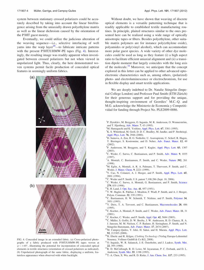
Eventually, we could utilize the judicious alteration of
the weaving sequence—i.e., selective interlacing of weft
yarns into the warp layer20—to fabricate intricate patterns
with the present P3HT/UHMW-PE tapes (Fig. 4). Interest-
ingly, the resulting image was readily apparent when investi-
gated between crossed polarizers but not when viewed in
unpolarized light. Thus, clearly, the here demonstrated wo-
ven systems permit facile production of concealed optical
features in seemingly uniform fabrics.
Without doubt, we have shown that weaving of discrete
optical elements is a versatile patterning technique that is
readily applicable to established textile manufacturing rou-
tines. In principle, plaited structures similar to the ones pre-
sented here can be realized using a wide range of optically
anisotropic tapes or fibers. Besides polyethylene, other suita-
ble matrix polymers are for instance poly(ethylene oxide),
polyamides or poly(vinyl alcohol), which can accommodate
more polar guest species. A wide variety of other dye mole-
cules could be used as long as they feature (i) a high aspect
ratio to facilitate efficient uniaxial alignment and (ii) a transi-
tion dipole moment that largely coincides with the long axis
of the molecule.34 Moreover, we anticipate that the concept
explored in this letter can be applied to other advanced opto-
electronic characteristics such as, among others, (polarized)
photo- and electroluminescence or electrochromism, for use
in flexible display and smart textile applications.
We are deeply indebted to Dr. Natalie Stingelin (Impe-
rial College London) and Professor Paul Smith (ETH Z€urich)
for their generous support and for providing the unique,
thought-inspiring environment of Geordies’ M.C.-Q. and
M.G. acknowledge the Ministerio de Econom�ıa y Competiti-
vidad for funding through Project No. PLE2009-0086.
1P. Dyreklev, M. Berggren, O. Ingan€as, M. R. Andersson, O. Wennerstr€om,
and T. Hjertberg, Adv. Mater. 7, 43 (1995).2M. Hamaguchi and K. Yoshino, Appl. Phys. Lett. 67, 3381 (1995).3K. S. Whitehead, M. Grell, D. D. C. Bradley, M. Jandke, and P. Strohriegl,
Appl. Phys. Lett. 76, 2946 (2000).4D. Sainova, A. Zen, H. G. Nothofer, U. Asawapirom, U. Scherf, R. Hagen,
T. Bieringer, S. Kostromine, and D. Neher, Adv. Funct. Mater. 12, 49
(2002).5P. Andersson, M. Berggren, and T. Kugler, Appl. Phys. Lett. 83, 1307
(2003).6C. Weder, C. Sarwa, C. Bastiaansen, and P. Smith, Adv. Mater. 9, 1035
(1997).7A. Montali, C. Bastiaansen, P. Smith, and C. Weder, Nature 392, 261
(1998).8M. Eglin, A. Montali, A. R. A. Palmans, T. Thervoort, P. Smith, and C.
Weder, J. Mater. Chem. 9, 2221 (1999).9Y. Cao, N. Colaneri, A. J. Heeger, and P. Smith, Appl. Phys. Lett. 65,
2001 (1994).10C. Weder and P. Smith, U.S. patent 7,108,286 (Sept. 18, 2006).11C. Weder, C. Sarwa, A. Montali, G. Bastiaansen, and P. Smith, Science
279, 835 (1998).12E. H. Land, J. Opt. Soc. Am. 41, 957 (1951).13T. W. Hagler, K. Pakbaz, J. Moulton, F. Wudl, P. Smith, and A. J. Heeger,
Polym. Commun. 32, 339 (1991).14C. Bastiaansen, H. W. Schmidt, T. Nishino, and P. Smith, Polymer 34,
3951 (1993).15Y. Dirix, T. A. Tervoort, and C. Bastiaansen, Macromolecules 28, 486
(1995).16C. Kocher, A. Montali, P. Smith, and C. Weder, Adv. Funct. Mater. 11, 31
(2001).17C. Kocher, C. Weder, and P. Smith, Appl. Opt. 42, 5684 (2003).18C. M€uller, S. Goffri, D. W. Breiby, J. W. Andreasen, H. D. Chanzy, R. A.
J. Janssen, M. M. Nielsen, C. P. Radano, H. Sirringhaus, P. Smith, and N.
Stingelin-Stutzmann, Adv. Funct. Mater. 17, 2674 (2007).19M. Campoy-Quiles, Y. Ishii, H. Sakai, and H. Murata, Appl. Phys. Lett.
92, 213305 (2008).20H. Eberle and R. Kilgus, Clothing Technology (Verlag Europa-Lehrmittel
Nourney, Vollmer GmbH & Co KG, 2008).21O. Ingan€as, W. R. Salaneck, J.-E. €Osterholm, and J. Laakso, Synth. Met.
22, 395 (1988).22R. D. McCullough, R. D. Lowe, M. Jayaraman, P. C. Ewbank, and D. L.
Anderson, Synth. Met. 55, 1198 (1993).23T.-A. Chen, X. Wu, and R. D. Rieke, J. Am. Chem. Soc. 117, 233 (1995).
FIG. 4. Concealed image in an extended fabric. (a) Cross-polarized photo-
graphs of a fabric produced with P3HT/UHMW-PE tapes woven at
u�645�, illustrating the potential for incorporation of concealed optical
elements in textile structures (orientation of crossed polarizers as indicated).
(b) Unpolarized photograph of the same fabric, displaying a uniform, fea-
tureless appearance when observed with white backlight.
171907-4 M€uller, Garriga, and Campoy-Quiles Appl. Phys. Lett. 101, 171907 (2012)
24H. Heil, T. Finnberg, N. von Malm, R. Schmechel, and H. von Seggern, J.
Appl. Phys. 93, 1636 (2003).25P. Parkinson, C. M€uller, N. Stingelin, M. B. Johnston, and L. M. Herz, J.
Phys. Chem. Lett. 1, 2788 (2010).26See supplementary material at http://dx.doi.org/10.1063/1.4764518 for op-
tical appearance of tapes woven at uB�690�; estimate of the birefrin-
gence; calculation of the contrast between two adjacent weaves of
opposite stacking sequence; and a plot of the maximum contrast as a func-
tion of uA.27H. M€uller, J. Opt. Soc. Am. 38, 661 (1948).
28G. G. Stokes, Trans. Cambrigde Philos. Soc. 9, 399 (1852).29Polarizer 1 is fixed at a¼ 0� and polarizer 2 at a¼ 90� (cf. Fig. 2(a)).30The drawing direction of tape 1 is oriented at h with respect to polarizer 1,
whereas tape 2 is oriented at hþu (cf. Fig. 2(a)).31G. G. Fuller, Optical Rheometry of Complex Fluids (Oxford University
Press, New York, 1995).32J. Schellman and H. P. Jensen, Chem. Rev. 87, 1359 (1987).33Y. J. L. Dirix, “Polarisers based on anisotropic absorbance or scattering of
light,” Ph.D. dissertation (TU/e, Eindhoven, 1997), p. 24.34E. W. Thulstrup and J. Michl, J. Am. Chem. Soc. 104, 5594 (1982).
171907-5 M€uller, Garriga, and Campoy-Quiles Appl. Phys. Lett. 101, 171907 (2012)