72
Pavement Marking Design Guidelines Delivery & Operations Division | Traffic-Roadway Section January 2022
Pavement Marking Design GuidelinesDelivery & Operations Division | Traffic-Roadway Section January 2022
Traffic-Roadway Section
Pavement Marking Design Guidelines
January 2022 page i
ODOT is an Equal Employment Opportunity and Affirmative Action Employer.
This information can be made available in alternative format by contacting 503-986-3568
ODOT does not discriminate on the basis of disability in admission or access to our programs,
services, activities, hiring and employment practices. Questions: 1-877-336-6368 (EEO-ODOT) or
through Oregon Relay Service at 7-1-1.
Oregon Department of Transportation
Engineering & Technical Services Branch
Traffic-Roadway
4040 Fairview Industrial Drive SE
Salem, Oregon 97302
503-986-3568
Traffic Engineering Website
Traffic-Roadway Section
Pavement Marking Design Guidelines
January 2022 page ii
Table of Contents
Preface ........................................................................................................................................... 1
Chapter 1: General Information ............................................................................................... 2
1.1 Responsibility for Pavement Marking Plans .................................................................................... 2
1.2 When Pavement Marking Plans are Required ................................................................................. 2
1.3 Useful Information for Plan Development ....................................................................................... 3
1.4 Coordination with Other Disciplines ................................................................................................ 4
Chapter 2: Survey Needs ........................................................................................................... 7
2.1 General ................................................................................................................................................... 7
2.2 Limits of Survey ................................................................................................................................... 7
Chapter 3: Plans, Specifications & Estimate Process ........................................................... 8
3.1 Scoping/Pre-DAP/Proof of Concept .................................................................................................. 8
3.2 Design Acceptance Plans .................................................................................................................... 8
3.3 Preliminary Plans ................................................................................................................................. 9
3.4 Advanced Plans .................................................................................................................................... 9
3.5 Final Plans Review ............................................................................................................................. 10
3.6 PS&E Package ..................................................................................................................................... 10
3.7 State Force Work ................................................................................................................................ 10
Chapter 4: Standard Drawings & Details ............................................................................. 11
4.1 Standard Drawings ............................................................................................................................ 11
4.2 Standard Details ................................................................................................................................. 12
Chapter 5: Material Selection ................................................................................................. 13
5.1 General ................................................................................................................................................. 13
5.2 Longitudinal Marking Materials ...................................................................................................... 16
5.3 Transverse Marking Materials ......................................................................................................... 17
5.4 Material Type Based on Project Type .............................................................................................. 18
5.5 Non-Standard Material and Applications ...................................................................................... 18
Chapter 6: Specifications & Special Provisions .................................................................. 20
6.1 General ................................................................................................................................................. 20
Traffic-Roadway Section
Pavement Marking Design Guidelines
January 2022 page iii
6.2 Preparing the Special Provisions ..................................................................................................... 21
Chapter 7: Estimate ................................................................................................................... 23
7.1 General ................................................................................................................................................. 23
7.2 Engineer’s Cost Estimate................................................................................................................... 23
Chapter 8: Post Bid Letting ...................................................................................................... 24
8.1 Addenda .............................................................................................................................................. 24
8.2 Construction Support ........................................................................................................................ 25
8.3 As-Constructed Plans ........................................................................................................................ 28
Chapter 9: Drafting Standards – General ............................................................................. 29
9.1 Creating Pavement Marking Design Files ...................................................................................... 29
9.2 File Naming Convention ................................................................................................................... 33
9.3 ODOT Pavement Marking Drafting Tool ....................................................................................... 35
9.4 Base File Augmentation .................................................................................................................... 36
9.5 Reference Files .................................................................................................................................... 37
9.6 Borders and Title Block ..................................................................................................................... 37
9.7 Sheet Size and Scale ........................................................................................................................... 40
9.8 V-Number ........................................................................................................................................... 40
9.9 Order of Pavement Marking Plans .................................................................................................. 40
Chapter 10: Drafting Standards – Plan Sheet Specific ....................................................... 41
10.1 Pavement Marking Details ............................................................................................................. 41
10.2 Pavement Marking Plan .................................................................................................................. 42
10.3 Striping Removal Plan ..................................................................................................................... 52
10.4 Pavement Marking Design Shown on Other Discipline’s Plan Sheets ..................................... 53
10.5 Temporary Striping Plan Sheets .................................................................................................... 53
Appendix A – References ........................................................................................................ 55
Appendix B – Designer Checklist .......................................................................................... 56
Appendix C – Example Project Title and Index Sheets ..................................................... 58
Appendix D – Example As-Constructed Plans .................................................................... 60
Appendix E – Examples of Pavement Marking Plans ........................................................ 63
Traffic-Roadway Section
Pavement Marking Design Guidelines
January 2022 page iv
This page has been intentionally left blank.
Traffic-Roadway Section
Pavement Marking Design Guidelines
January 2022 page 1
Preface
The purpose of this manual is to:
Provide information and guidance to the designer regarding the pavement marking
(striping, rumble strips, and delineators) contract plan development process.
Provide drafting standards for pavement marking (striping, rumble strips, and
delineators) plans.
Ensure statewide consistency in contract plan development.
For information on pavement marking design standards and policies, the designer should refer
to the current version of:
The ODOT Traffic Line Manual.
The Manual on Uniform Traffic Control Devices (MUTCD).
The Oregon Supplement to the MUTCD.
Oregon Standard Drawings and Standard Details.
The ODOT Traffic Manual.
Technical directives, bulletins and advisories.
These guidelines contain references to documents that will be periodically changed or updated,
such as the ODOT Traffic Line Manual, standard drawings, and boilerplate special provisions.
See Appendix A for web links to all of the resources.
Design standards and guidance may also be updated via a technical directive, technical bulletin,
or a technical advisory prior to updating manuals.
Updating this manual is a continuing process and revisions are issued as required. Questions or
suggestions for modifications should be addressed to:
Traffic Markings & Sign Engineer
4040 Fairview Ind. Dr. SE MS #5
Salem, OR 97302
503-986-3610
This manual is a web-only document, which can be accessed and printed in its entirety from the
ODOT Traffic Engineering Section publications website.
Traffic-Roadway Section
Pavement Marking Design Guidelines
January 2022 page 2
Chapter 1: General Information
1.1 Responsibility for Pavement Marking Plans The responsibility for the preparation of pavement marking plans on state highways rests with
either the traffic designer or roadway designer assigned. If possible, traffic designers should
prepare pavement marking plans.
The region traffic engineer/manager shall review and approve all pavement marking plans
regardless of who designs and/or stamps the plans. The region traffic engineer/manager may
delegate this responsibility to a member or members of their staff competent in pavement
marking design. The title block on the pavement marking plan sheets shall list either the region
traffic engineer/manager’s name or the delegated staff member’s name in the “Reviewed By”
location. See Section 9.6 for more information on the title block. The review process should take
place during different phases of the project (e.g., design acceptance phase, preliminary,
advanced, final, etc.).
Certain pavement marking design elements require state traffic engineer or region traffic
engineer approval. The region Traffic Section is responsible for obtaining any such approval.
See the ODOT Traffic Line Manual and the ODOT Traffic Manual for detailed information
regarding delegated authority and design elements requiring approval.
1.2 When Pavement Marking Plans are Required Sealed pavement marking plans are required for any project or maintenance activity where the
existing pavement marking configuration will be modified. This includes maintenance, 1R, 3R
and new construction projects.
Sealed pavement marking plans are strongly encouraged for any project or maintenance activity
where the existing pavement markings will be replaced in-kind, which typically includes
preservation and chip seal projects. Pavement marking plans for replace in-kind projects are
particularly helpful and well worth the time to produce for complex urban locations,
interchanges, and signalized intersections. Pavement marking plans are encouraged for the
following reasons:
Creation of a pavement markings plan will ensure that project conforms to current
standards: Existing pavement markings on a project may not conform to current
standards. While not all pavement marking standards can be updated on a preservation
job (e.g., those standards that are directly related to roadway improvements such as
increasing storage lengths, increasing shoulder widths, or tapers), many pavement
marking standards can, and should, be updated. For example correcting lengths of no-
passing markings, adding lane use arrows as required, changing line type, etc.
Traffic-Roadway Section
Pavement Marking Design Guidelines
January 2022 page 3
Creation of a pavement marking plan will aid field personnel during construction:
The contractor is required per the specifications to provide documentation of the
existing pavement markings prior to starting replace in-kind work. However, this
documentation is often done quickly and may lack necessary details, resulting in
increased chance for installation errors. Pavement marking plans makes field layout
easier and quicker for both the contractor and the inspector.
Creation of a pavement marking plan will lessen the chance for installation errors: It
is important for the pavement marking installation to be correct on the first application.
Removal of mistakes is expensive and unforgiving (especially when using durable
materials). If a mistake is made, removal of markings from the new pavement surface is
often the only answer. Not only does this look ugly, but it creates “ghost lines” (the
location of the ground-out pavement marking which remains visible to the motorist,
especially in rainy conditions). It is less likely that an error will be made in the field if a
pavement marking plan is produced ahead of time. There also is the benefit of allowing
others the opportunity to review and provide comment.
Creation of a pavement marking plan will aid the designer in developing the bid item
list and enable a more accurate cost estimate: Accurate bid item lists and cost estimates
are crucial to the construction office administering the project. Inaccurate bid items and
cost estimates can lead to confusion, wasted time, and an increased construction cost.
Creation of a pavement marking plan documents the decisions of the engineer of
record: Documentation is always valuable, should issues arise in the future.
If the designer chooses not to produce pavement marking plans for replace-in-kind work,
Section 00850.40 of the Oregon Standard Specifications for Construction instructs the contractor
how to document and replace the existing pavement marking. The designer will still need to
prepare the special provisions, bid item list and cost estimate for the project.
1.3 Useful Information for Plan Development Before starting, the items listed below will help guide a designer in the initial stages of the
pavement marking design.
Review and become familiar with the current ODOT Traffic Line Manual.
o Other documents such as the Oregon Standard Drawings, Oregon Standard
Details, Manual on Uniform Traffic Control Devices (MUTCD), Oregon
Supplement to the MUTCD, and the ODOT Traffic Manual will be helpful for
source information, but the Traffic Line Manual should always be referenced for
pavement marking design information.
Review the Technical Directives, Bulletins, and Advisories website before each project to
ensure that the most current design guidance is used.
A copy of signed approval letter(s) from the state traffic engineer or region traffic
engineer for any pavement marking design elements that require approval.
Traffic-Roadway Section
Pavement Marking Design Guidelines
January 2022 page 4
o Refer to the ODOT Traffic Line Manual and the ODOT Traffic Manual for
detailed information regarding delegated authority and design elements
requiring approval.
Railroad pavement markings are typically specified in the railroad crossing order.
o A copy of the railroad crossing order for any design criteria that will impact
pavement marking design can be obtained from the rail crossing safety manager
at 503-986-4273.
Designers determine which features pavement marking plans include. Consider the following:
How are the roadway plans laid out? Pavement marking plans shall have the same
alignment orientation, display and cut sheet layout as the roadway plans.
Are there any recent changes in the pavement marking practices/policies that may affect
the design?
o Crosswalk orientation aligning with new Americans with Disabilities Act (ADA)
ramps.
o Rumble strip widths verified by region traffic engineer.
o Transverse marking use and fish hook arrows at roundabouts.
Are there any unique details not covered in the standard drawings?
o Rumble strips.
o Unique legends.
Will the project include removal of existing pavement markings?
o Changing passing zone lengths due to speed changes.
o Adjusting markings for matching existing.
o Adjusting markings to new standards.
Is there a need to modify existing pavement markings outside of the project limits?
Will required survey data be available for the proposed installation?
o If not can LIDAR data or Google Earth aerial imagery be used to draw in existing
linework?
What pavement marking material(s) will be used in the project?
o Check the region striping plan.
o Check with the district striping maintenance manager.
1.4 Coordination with Other Disciplines Designing the pavement markings requires coordination with other disciplines throughout the
design process.
Pavement marking design is unique from most other technical disciplines in that two separate
disciplines typically produce pavement marking plans:
A roadway designer producing pavement marking plans needs to coordinate with the
signing and signals designers.
Traffic-Roadway Section
Pavement Marking Design Guidelines
January 2022 page 5
A traffic designer producing pavement marking plans needs to coordinate with the
roadway, signing and signals designers.
Roadway Coordination with the roadway designer is critical. The development of pavement marking
plans normally occurs after the roadway design has been established. The roadway design is
the foundation for placement of traffic control devices. The traffic designer should be involved
early in the process to provide input into the roadway design. Certain pavement marking
situations should be considered and laid-out in the early stages of the roadway design process
(when cross-section changes can be easily made) to ensure that the traffic operation functions as
intended and traffic control devices can be installed properly. These situations include, but are
not limited to:
Lane reduction transitions (merging situations).
Lane addition transitions.
Intersections (crosswalk placement, stop bar placement, turn lane development, truck
turning radii, etc.).
Entrance and exit ramps.
Mid-block crosswalks.
Raised median or channelizing islands.
No-passing sight distance.
Left/right turn lane storage length.
Bicycle lanes and transitions.
Traffic Pavement markings provide important traffic control information to motorists, bicyclists, and
pedestrians, and have a direct effect on traffic operations, so coordination with the region’s
Traffic Section, the active transportation liaison, and the regional transit and rail coordinator is
critical. For certain pavement marking situations, as mentioned above, the roadway designer
should coordinate with the region’s Traffic Section early in the design process (when cross-
section changes can be easily made) to ensure that the roadway design is appropriate for the
intended traffic operation.
In addition, there are certain pavement marking design elements that require an engineering
study and approval from the region traffic engineer or state traffic engineer. These approvals
should be started (verbally or at meetings) prior to the final design acceptance phase (DAP)
milestone and obtained prior to the finished preliminary milestone. The region’s Traffic Section
is responsible for obtaining all necessary traffic approvals on a project. See Traffic Line Manual
“Required Approvals” sections.
Traffic-Roadway Section
Pavement Marking Design Guidelines
January 2022 page 6
Signing In many cases, pavement markings are used as primary traffic control devices to convey
regulations and the signing may supplement pavement markings. For example:
A “DO NOT PASS” sign is supplemental to a no-passing pavement marking line.
A “Two-Way Left Turn Only” sign is supplemental to a two-way left turn lane
pavement marking line.
In some cases, pavement markings are used to supplement other traffic control devices, such as
signs. For example:
A stop bar is supplemental to a “STOP” sign.
A “SCHOOL X-ING” marking is supplemental to an advance school warning assembly
sign.
A yield line is supplemental to a “YIELD” sign.
There are also cases where both signing and pavement markings must be used together to
convey traffic regulations to motorists. For example:
Lane reduction transitions.
Lane drop(s).
On street parking.
Railroad crossings.
Midblock crosswalks.
Advance stop bars in advance of mid-block crosswalks.
Preferential lanes.
Coordinate pavement marking design with sign design depending on which traffic control
device is the primary device.
Signals Pavement marking design at signalized intersections is important, ensuring the signal will
function as intended. Certain elements, such as detection, vehicle signal indications and
pedestrian signal indications require coordinated placement with the pavement markings.
Critical elements at a signalized intersection include:
Crosswalk or stop bar placement.
Lane use.
Storage lengths of turn lanes.
The signal designer generally designs the equipment to fit within the pavement marking
design. Make sure to inform the signal designer if significant changes are made to the pavement
marking design just prior to submittal.
Traffic-Roadway Section
Pavement Marking Design Guidelines
January 2022 page 7
Chapter 2: Survey Needs
2.1 General Survey information needed for pavement marking designs varies depending on the scope of the
projects. However, the following information is typically needed for pavement marking design:
Edge of asphalt pavement.
Edge of concrete pavement.
Edge of concrete at bridge decks.
Face of curb (for sidewalks, raised channelizing islands, etc.).
Face of guardrail.
Location of ADA ramps.
Location of signs.
Location of signal heads.
Existing pavement marking (lane lines, edge lines, extension lines, centerline,
crosswalks, stop bars, legends, etc.).
Location of concrete barriers, cable barriers, bridge rails, etc.
2.2 Limits of Survey The survey should extend at least 200-300 feet outside of established project limits to
enable a good tie-in to existing pavement marking.
Certain projects require centerline/lane line information 1,600 feet or more outside of
established project limits to ensure that no-passing zones or lane line markings are
appropriately installed, such as:
- Addition of left turn lane channelization or a median.
- Addition of right turn lane channelization.
- Conversion of a drop lane to a non-drop lane or vice versa.
- Modification of horizontal or vertical alignment.
- Roadway realignment.
Traffic-Roadway Section
Pavement Marking Design Guidelines
January 2022 page 8
Chapter 3: Plans, Specifications & Estimate
Process
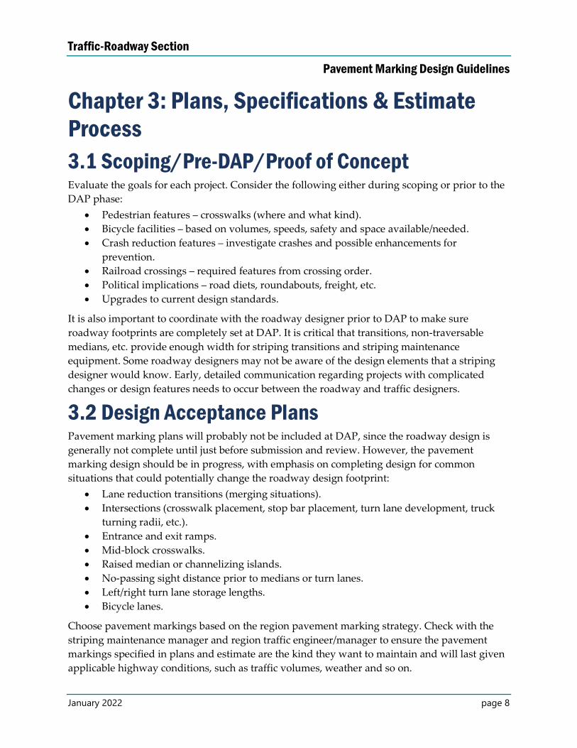
3.1 Scoping/Pre-DAP/Proof of Concept Evaluate the goals for each project. Consider the following either during scoping or prior to the
DAP phase:
Pedestrian features – crosswalks (where and what kind).
Bicycle facilities – based on volumes, speeds, safety and space available/needed.
Crash reduction features – investigate crashes and possible enhancements for
prevention.
Railroad crossings – required features from crossing order.
Political implications – road diets, roundabouts, freight, etc.
Upgrades to current design standards.
It is also important to coordinate with the roadway designer prior to DAP to make sure
roadway footprints are completely set at DAP. It is critical that transitions, non-traversable
medians, etc. provide enough width for striping transitions and striping maintenance
equipment. Some roadway designers may not be aware of the design elements that a striping
designer would know. Early, detailed communication regarding projects with complicated
changes or design features needs to occur between the roadway and traffic designers.
3.2 Design Acceptance Plans Pavement marking plans will probably not be included at DAP, since the roadway design is
generally not complete until just before submission and review. However, the pavement
marking design should be in progress, with emphasis on completing design for common
situations that could potentially change the roadway design footprint:
Lane reduction transitions (merging situations).
Intersections (crosswalk placement, stop bar placement, turn lane development, truck
turning radii, etc.).
Entrance and exit ramps.
Mid-block crosswalks.
Raised median or channelizing islands.
No-passing sight distance prior to medians or turn lanes.
Left/right turn lane storage lengths.
Bicycle lanes.
Choose pavement markings based on the region pavement marking strategy. Check with the
striping maintenance manager and region traffic engineer/manager to ensure the pavement
markings specified in plans and estimate are the kind they want to maintain and will last given
applicable highway conditions, such as traffic volumes, weather and so on.
Traffic-Roadway Section
Pavement Marking Design Guidelines
January 2022 page 9
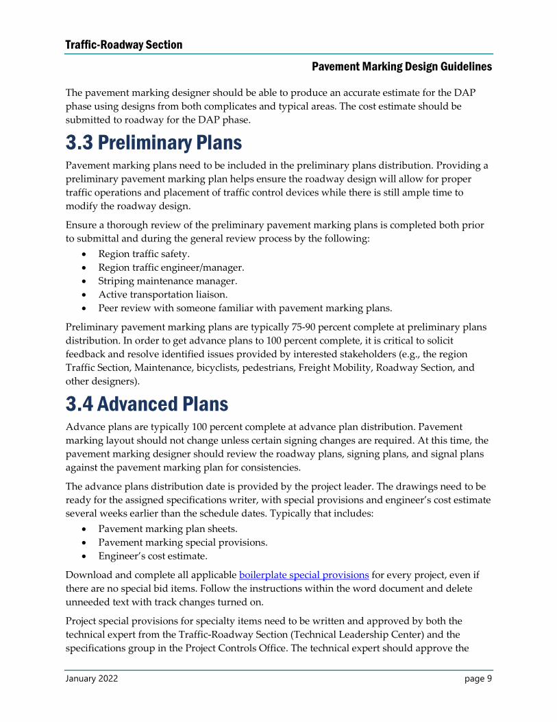
The pavement marking designer should be able to produce an accurate estimate for the DAP
phase using designs from both complicates and typical areas. The cost estimate should be
submitted to roadway for the DAP phase.
3.3 Preliminary Plans Pavement marking plans need to be included in the preliminary plans distribution. Providing a
preliminary pavement marking plan helps ensure the roadway design will allow for proper
traffic operations and placement of traffic control devices while there is still ample time to
modify the roadway design.
Ensure a thorough review of the preliminary pavement marking plans is completed both prior
to submittal and during the general review process by the following:
Region traffic safety.
Region traffic engineer/manager.
Striping maintenance manager.
Active transportation liaison.
Peer review with someone familiar with pavement marking plans.
Preliminary pavement marking plans are typically 75-90 percent complete at preliminary plans
distribution. In order to get advance plans to 100 percent complete, it is critical to solicit
feedback and resolve identified issues provided by interested stakeholders (e.g., the region
Traffic Section, Maintenance, bicyclists, pedestrians, Freight Mobility, Roadway Section, and
other designers).
3.4 Advanced Plans Advance plans are typically 100 percent complete at advance plan distribution. Pavement
marking layout should not change unless certain signing changes are required. At this time, the
pavement marking designer should review the roadway plans, signing plans, and signal plans
against the pavement marking plan for consistencies.
The advance plans distribution date is provided by the project leader. The drawings need to be
ready for the assigned specifications writer, with special provisions and engineer’s cost estimate
several weeks earlier than the schedule dates. Typically that includes:
Pavement marking plan sheets.
Pavement marking special provisions.
Engineer’s cost estimate.
Download and complete all applicable boilerplate special provisions for every project, even if
there are no special bid items. Follow the instructions within the word document and delete
unneeded text with track changes turned on.
Project special provisions for specialty items need to be written and approved by both the
technical expert from the Traffic-Roadway Section (Technical Leadership Center) and the
specifications group in the Project Controls Office. The technical expert should approve the
Traffic-Roadway Section
Pavement Marking Design Guidelines
January 2022 page 10
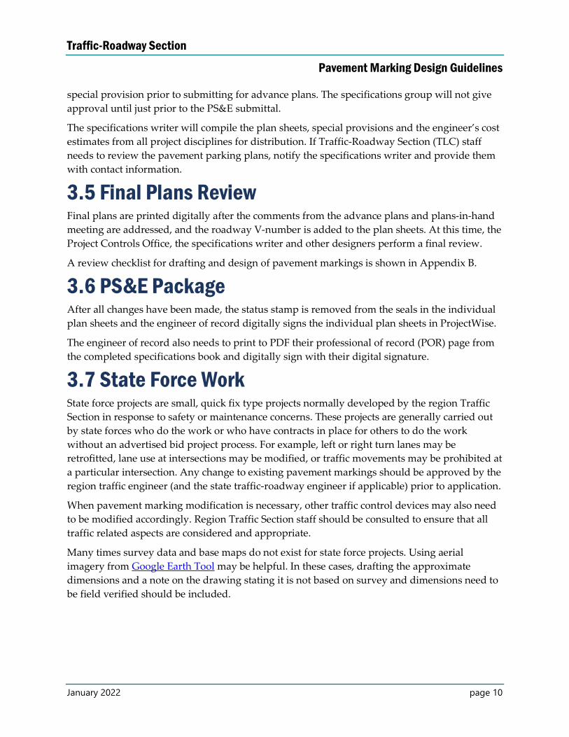
special provision prior to submitting for advance plans. The specifications group will not give
approval until just prior to the PS&E submittal.
The specifications writer will compile the plan sheets, special provisions and the engineer’s cost
estimates from all project disciplines for distribution. If Traffic-Roadway Section (TLC) staff
needs to review the pavement parking plans, notify the specifications writer and provide them
with contact information.
3.5 Final Plans Review Final plans are printed digitally after the comments from the advance plans and plans-in-hand
meeting are addressed, and the roadway V-number is added to the plan sheets. At this time, the
Project Controls Office, the specifications writer and other designers perform a final review.
A review checklist for drafting and design of pavement markings is shown in Appendix B.
3.6 PS&E Package After all changes have been made, the status stamp is removed from the seals in the individual
plan sheets and the engineer of record digitally signs the individual plan sheets in ProjectWise.
The engineer of record also needs to print to PDF their professional of record (POR) page from
the completed specifications book and digitally sign with their digital signature.
3.7 State Force Work State force projects are small, quick fix type projects normally developed by the region Traffic
Section in response to safety or maintenance concerns. These projects are generally carried out
by state forces who do the work or who have contracts in place for others to do the work
without an advertised bid project process. For example, left or right turn lanes may be
retrofitted, lane use at intersections may be modified, or traffic movements may be prohibited at
a particular intersection. Any change to existing pavement markings should be approved by the
region traffic engineer (and the state traffic-roadway engineer if applicable) prior to application.
When pavement marking modification is necessary, other traffic control devices may also need
to be modified accordingly. Region Traffic Section staff should be consulted to ensure that all
traffic related aspects are considered and appropriate.
Many times survey data and base maps do not exist for state force projects. Using aerial
imagery from Google Earth Tool may be helpful. In these cases, drafting the approximate
dimensions and a note on the drawing stating it is not based on survey and dimensions need to
be field verified should be included.
Traffic-Roadway Section
Pavement Marking Design Guidelines
January 2022 page 11
Chapter 4: Standard Drawings & Details
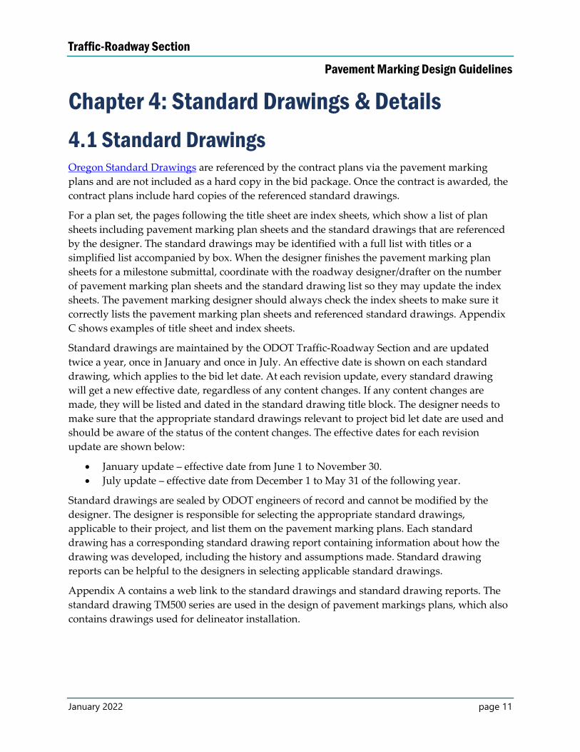
4.1 Standard Drawings Oregon Standard Drawings are referenced by the contract plans via the pavement marking
plans and are not included as a hard copy in the bid package. Once the contract is awarded, the
contract plans include hard copies of the referenced standard drawings.
For a plan set, the pages following the title sheet are index sheets, which show a list of plan
sheets including pavement marking plan sheets and the standard drawings that are referenced
by the designer. The standard drawings may be identified with a full list with titles or a
simplified list accompanied by box. When the designer finishes the pavement marking plan
sheets for a milestone submittal, coordinate with the roadway designer/drafter on the number
of pavement marking plan sheets and the standard drawing list so they may update the index
sheets. The pavement marking designer should always check the index sheets to make sure it
correctly lists the pavement marking plan sheets and referenced standard drawings. Appendix
C shows examples of title sheet and index sheets.
Standard drawings are maintained by the ODOT Traffic-Roadway Section and are updated
twice a year, once in January and once in July. An effective date is shown on each standard
drawing, which applies to the bid let date. At each revision update, every standard drawing
will get a new effective date, regardless of any content changes. If any content changes are
made, they will be listed and dated in the standard drawing title block. The designer needs to
make sure that the appropriate standard drawings relevant to project bid let date are used and
should be aware of the status of the content changes. The effective dates for each revision
update are shown below:
January update – effective date from June 1 to November 30.
July update – effective date from December 1 to May 31 of the following year.
Standard drawings are sealed by ODOT engineers of record and cannot be modified by the
designer. The designer is responsible for selecting the appropriate standard drawings,
applicable to their project, and list them on the pavement marking plans. Each standard
drawing has a corresponding standard drawing report containing information about how the
drawing was developed, including the history and assumptions made. Standard drawing
reports can be helpful to the designers in selecting applicable standard drawings.
Appendix A contains a web link to the standard drawings and standard drawing reports. The
standard drawing TM500 series are used in the design of pavement markings plans, which also
contains drawings used for delineator installation.
Traffic-Roadway Section
Pavement Marking Design Guidelines
January 2022 page 12
4.2 Standard Details Oregon Standard Details typically contain installation information that is either used
infrequently, used on non-state highway roadways, and/or must be modified based on the
project-specific situations.
Designers use standard details to create project-specific pavement marking detail plan sheets.
They are included in the contract plans set and sealed by the engineer of record. The designer
can and should modify standard details to fit unique, project-specific requirements. Often there
are notes to the designer in the standard detail containing further information on the
appropriate use and modification of the detail.
Standard details are maintained and updated by the Traffic-Roadway Section and can be
updated at any time. Designers should always download a copy from the website to ensure the
most up-to-date detail is used.
The standard details from DET4500 to DET4599 are used in design of pavement marking plans.
This series also contains drawings used for rumble strip installation.
Traffic-Roadway Section
Pavement Marking Design Guidelines
January 2022 page 13
Chapter 5: Material Selection
5.1 General The decision to select a certain material and application method for a project rests with the
region striping maintenance manager, with concurrence from the region traffic engineer.
The region striping maintenance manager is responsible for creating and maintaining a
pavement marking material management plan for the entire region. This plan is available upon
request and should be used as a guide when scoping and designing projects.
Materials and application methods should be selected such that they meet or exceed the
performance requirements at the lowest cost. To maximize cost-effectiveness, material selection
should be based on:
Roadway surface type.
Traffic volume.
Expected remaining service life of the pavement.
Future expected projects.
Pavement markings of the adjacent sections.
Available funding and ability to maintain.
Also, there may be a need to use markings with audible and tactile characteristics based on
crash history or markings with wet weather performance depending on geographical location.
Since the region striping maintenance manager and traffic engineer have different levels of
knowledge related to the various material selection considerations, both perspectives should be
involved in selecting the material and application for a project.
Materials need to be selected separately for longitudinal and for transverse markings. In some
cases, multiple materials and/or application methods for longitudinal and/or transverse
markings on the same project may be specified in order to meet the chosen performance
requirements within the project budget. For example, a non-profiled line (Method B) may be
adequate for lane line markings, but a more expensive profiled line (Method A) may be desired
for the edge line or centerline to address lane departure crashes.
Project scheduling will directly affect the quality of permanent striping. Most permanent
materials require an ambient air temperature of at least 50°F and dry pavement. Hot-laid
materials like thermoplastic are especially sensitive to moisture. Even if the surface is dry, the
heat of the material can draw moisture from deeper in the pavement and affect the marking’s
bond to the pavement.
In most areas, permanent materials should be installed before September 15 to meet these
temperature and moisture requirements. If permanent striping is not installed by this time, less
durable temporary markings that can be installed at lower temperatures may need to be used to
Traffic-Roadway Section
Pavement Marking Design Guidelines
January 2022 page 14
winter-over the project. This may be difficult to achieve for paving projects, but projects without
paving should use an end date that keeps an acceptable striping weather window.
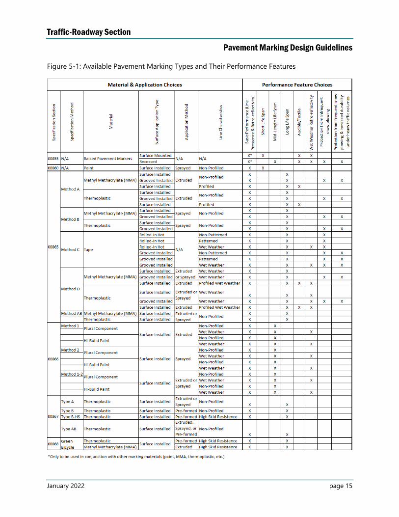
Figure 5.1 shows different types of longitudinal and transverse pavement marking types
available for use along with their performance features. Specification sections 00850 through
00868 contain installation information.
Traffic-Roadway Section
Pavement Marking Design Guidelines
January 2022 page 15
Figure 5-1: Available Pavement Marking Types and Their Performance Features
Traffic-Roadway Section
Pavement Marking Design Guidelines
January 2022 page 16
The designer does NOT need to specify the following for a project (see the specifications and
bid item section of this manual for more information):
Reflective elements (as per the qualified products list – QPL listing or manufacturer’s
recommendation via specification).
Specific material formula (as per the QPL listing via specification).
Pavement surface primers or pavement surface preparation (as per manufacturer’s
recommendation via specification).
Adhesives for raised pavement markers (RPMs) (contractor choice of epoxy or
bituminous via specification).
Application methods for certain materials (pre-defined via specification or standard
drawing).
Thickness of materials (pre-defined via specification or standard drawing).
5.2 Longitudinal Marking Materials Materials for longitudinal markings can be divided into three general categories: non-durable,
durable and other.
Non-durable marking material is standard waterborne traffic paint. This is the least
expensive marking material and has a relatively short service life. Installation
information is contained in specification section 00860.
Durable marking materials offer performance features above and beyond what a non-
durable marking material can provide. These materials are more expensive to install but
have a longer service life than non-durable marking material. Installation information of
durable markings is contained in specification section 00865.
o Thermoplastic.
Profiled or non-profiled.
Surface or groove installed.
Extrusion or spray.
o Methyl Methacrylate (MMA).
Profiled or non-profiled.
Surface or groove installed.
Extrusion or spray.
o Tape.
Hot-laid or groove installed.
May be patterned. Installation information of durable markings is
contained in specification section 00865.
High Performance Markings
o Modified urethane epoxy (plural component).
o Polyurea.
o High-build paint.
Traffic-Roadway Section
Pavement Marking Design Guidelines
January 2022 page 17
o Offer a mid-range life cycle, somewhere between the performance of a non-
durable and a durable marking material.
Raised Pavement Markers
o Type I – Reflective.
Raised or recessed.
Abrasion resistant (AR).
Used to supplement other marking materials or used as vehicle
positioning guide.
o Type II – Non-reflective.
o Installation information is contained in specification sections 00855 and 00866 for
pavement markers and high performance pavement markings, respectively.
5.3 Transverse Marking Materials Materials for transverse markings are required to be a durable product. Installation information
is contained in specification section 00867 and special provision 00868. There is only one
material available for use, thermoplastic, with four different options:
Type A, thermoplastic, liquid hot-laid – This method involves melting a tank of
material and either spraying the material over a stencil form or extruding the material.
This method is economical when there is a large quantity of legends to be installed as
specialized equipment must be mobilized and a large amount of thermoplastic must be
melted for use in the equipment.
Type B, thermoplastic, preformed – This method involves hardened, preformed pieces
of thermoplastic that are placed on the pavement and melted in-place by a torch. This
method is economical when there is a small quantity of legends to be installed or the
project is in a remote location.
Type B-HS, thermoplastic, preformed high-skid – This method is the same as Type B,
but incorporates crushed glass or aggregate on the surface creating a marking with
greater skid resistant characteristics. This method is required (via the specifications and
bid items) for certain markings that have a high probability of contact with bicycles or
pedestrians, such as continental crosswalk markings and bike lane stencils.
Type AB, thermoplastic – This method allows the contractor to choose either Type A,
Type B or Type B-HS as defined above. This method should be used as the default
material type on your project for all legends (with the exception of those markings that
must be Type B-HS) unless the region striping manager requests a specific legend
material type be used.
Green bicycle lane, preformed thermoplastic film – This method is a green colored
version of Type B-HS thermoplastic used exclusively in the bike lanes/transitions to give
added emphasis to the presence of a bike lane in high conflict areas or at intersections.
Green bicycle lane, methyl methacrylate – This method can be used instead of the
thermoplastic film by mixing the methyl methacrylate chemicals with crushed glass or
Traffic-Roadway Section
Pavement Marking Design Guidelines
January 2022 page 18
aggregate and them spreading in an even thickness across the pavement area being
marked.
Red transit lane, preformed thermoplastic film – This method is a green colored
version of Type B-HS thermoplastic used exclusively in the bike lanes/transitions to give
added emphasis to the presence of a transit only lane.
Red transit lane, methyl methacrylate – This method can be used instead of the
thermoplastic film by mixing the methyl methacrylate chemicals with crushed glass or
aggregate and them spreading in an even thickness across the pavement area being
marked.
Two other material types have been used in the past by ODOT, but are no longer used:
Type C, tape – ODOT discontinued this method in 2007 due to low usage and
performance issues in prior years.
Type D, methyl methacrylate – ODOT discontinued this method in 2009 due to low
usage, environmental and health concerns and maintenance issues.
5.4 Material Type Based on Project Type Different regions may develop their own policies for durable pavement marking as related to
project development. Region policy should be followed, if it exists. Region Traffic
engineer/manager and the region pavement markings manager should be contacted to find out
if a region has a policy. If the region does not have a policy, use the guidelines below.
Modernization Projects – Typically specify a durable longitudinal line whenever
feasible. When this is not a viable option (based on funding), explore and plan for the
following options.
1. Use a non-durable line on the current project, and a separate (future) contract to
install durable markings. Durable marking only contracts often include other
areas that have non-durable markings in need of upgrade.
2. The region pavement marking crew may be able to commit to applying durable
markings during the next scheduled re-striping.
Preservation Projects – Typically replace the existing material type in-kind, unless there
is a reason to change. If replacing an existing durable material in-kind is not a viable
option (based on funding), evaluate the two options detailed in the modernization
projects subheading.
5.5 Non-Standard Material and Applications Generally, the designer is responsible for specifying the standard marking materials and
applications, per the current specifications and qualified products list. However, there may be
cases where a non-standard material or application method may be considered, such as a local
agency requesting a colored or textured crosswalks (see the ODOT Traffic Line Manual for
information on ODOT’s policy.) There are also placeholders listed in the standard specification
Traffic-Roadway Section
Pavement Marking Design Guidelines
January 2022 page 19
bid item list (e.g., methyl methacrylate, protected inlaid, wet weather pattern, and extruded)
that do not have corresponding specifications or standard drawings/details. In these cases,
contact the Traffic-Roadway Section for assistance in developing plans and specifications.
Traffic-Roadway Section
Pavement Marking Design Guidelines
January 2022 page 20
Chapter 6: Specifications & Special Provisions
6.1 General Typically, two separate documents are needed to complete the project specifications (both can
be found on the ODOT Standard Specifications web page):
The current version of the “Oregon Standard Specifications for Construction.”
Boilerplate special provisions.
The “Oregon Standard Specifications for Construction” is a published book, also known as
standard specifications, and remains static for five to ten years. On the other hand, special
provisions add, modify, and/or delete portions of the standard specifications, based on project-
specific needs. The special provisions are intended to supplement or supersede the information
in the standard specifications.
If an item or type of work is shown in the plans, it must have the appropriate special provision
included in the contract documents for that project. Some of the boilerplate special provisions
do not actually contain any updated information but simply make reference to the standard
specifications. These boilerplate special provisions must still be included in the contract
documents. Always download the most recent copies of the boilerplate special provisions for
each project and check prior to finalizing them for your project since modifications can occur at
any time.
Background information on standard specifications, special provisions and guidance for writing
construction contact specifications can be found at the ODOT Standard Specifications web page.
The following is a list of specifications and special provisions that are related to pavement
markings:
00840 – Delineators and Milepost Marker Posts
00850 – Common Provisions for Pavement Markings
00225 – Pavement Marking Removal
00855 – Pavement Markers
00856 – Surface Mounted Tubular Markers
00857 – Rumble Strips
00860 – Longitudinal Pavement Markings – Paint
00865 – Longitudinal Pavement Markings – Durable
00866 – Longitudinal Pavement Markings – High Performance
00867 – Transverse Pavement Markings – Legends and Bars
00868 – Colored Lane Markings
00869 – Curb and Non-Traversable Median Markings
Traffic-Roadway Section
Pavement Marking Design Guidelines
January 2022 page 21
6.2 Preparing the Special Provisions Below is an outline of the step-by-step process required in the preparation of the special
provisions:
Determine which specifications are applicable to your project.
Download the current boilerplate special provision of each applicable section.
Edit each boilerplate special provision according to instructions within the boilerplate to
meet your project needs.
o Use Microsoft Word with “track changes” turned on.
If track changes is not used, review and future modifications become
difficult.
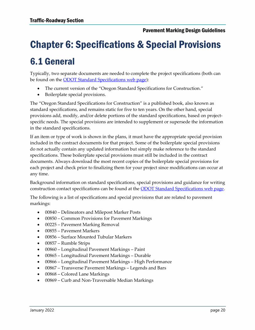
o Instructions to the designer are provided in orange, bold and italic font within
parentheses (Figure 6.2-1).
o Remove the instructions from the special provisions. It will appear in the balloon
in the right margin.
o Edit the boilerplate special provision as necessary depending on the project
needs.
o Any modification of boilerplate special provision, which is not mentioned in the
instructions, requires the technical expert’s review and approval, as well as
review and approval from the specifications team. Refer to Appendix A for the
specification technical expert list.
Figure 6.2-1: Example Special Provisions Instructions
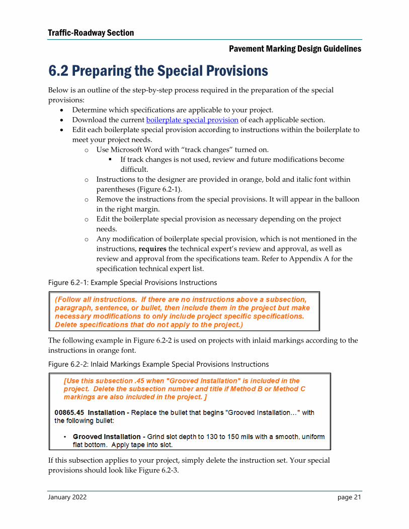
The following example in Figure 6.2-2 is used on projects with inlaid markings according to the
instructions in orange font.
Figure 6.2-2: Inlaid Markings Example Special Provisions Instructions
If this subsection applies to your project, simply delete the instruction set. Your special
provisions should look like Figure 6.2-3.
Traffic-Roadway Section
Pavement Marking Design Guidelines
January 2022 page 22
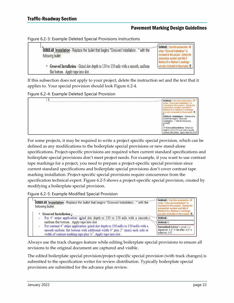
Figure 6.2-3: Example Deleted Special Provisions Instructions
If this subsection does not apply to your project, delete the instruction set and the text that it
applies to. Your special provision should look Figure 6.2-4.
Figure 6.2-4: Example Deleted Special Provision
For some projects, it may be required to write a project specific special provision, which can be
defined as any modifications to the boilerplate special provisions or new stand-alone
specifications. Project-specific provisions are required when current standard specifications and
boilerplate special provisions don’t meet project needs. For example, if you want to use contrast
tape markings for a project, you need to prepare a project-specific special provision since
current standard specifications and boilerplate special provisions don’t cover contrast tape
marking installation. Project-specific special provisions require concurrence from the
specification technical expert. Figure 6.2-5 shows a project-specific special provision, created by
modifying a boilerplate special provision.
Figure 6.2-5: Example Modified Special Provision
Always use the track changes feature while editing boilerplate special provisions to ensure all
revisions to the original document are captured and visible.
The edited boilerplate special provision/project-specific special provision (with track changes) is
submitted to the specification writer for review distribution. Typically boilerplate special
provisions are submitted for the advance plan review.
Traffic-Roadway Section
Pavement Marking Design Guidelines
January 2022 page 23
Chapter 7: Estimate
7.1 General Bid items are defined in the standard specifications and special provisions in each respective
pavement marking specification section.
Generally, the designer uses the bid item list provided online (refer to Appendix A). The Traffic-
Roadway Section specifications technical expert may change or modify bid items at any time, so
it is always a good idea to obtain the most recent copy from the website for each project. If a
unique bid item is required for a project, approval from the Traffic-Roadway Section
specifications technical expert is required.
7.2 Engineer’s Cost Estimate Once the appropriate bid items are chosen, a cost estimate must be completed. The bid item
costs are based on:
Historical data.
Available industry data.
Manufacturer quotes and project specific research.
ODOT’s average bid item prices can be obtained online.
Traffic-Roadway Section
Pavement Marking Design Guidelines
January 2022 page 24
Chapter 8: Post Bid Letting
8.1 Addenda Changes to the plans, special provisions, or bid items during the advertisement period are made
by addenda. The earlier an addenda is posted the more time contractors will have to properly
address the changes. Issuing multiple addenda is preferred over one large last minute addenda.
Last minute addenda can cause prospective bidders to withdraw from bidding and/or include
unnecessary risk pricing. Large last minute addenda are also difficult to review quickly and
often result in a postponement when contractors find errors that must be fixed.
All unsolicited issues, questions and inquiries from contractors and others will be directed to
the construction project manager per Standard Specification Section 00120.15 and the ODOT
Construction Manual, Chapter 6 (refer to Appendix A for website). All inquiries must go
through the construction project manager; a single, non-conflicting answer from ODOT (that
can be issued to all bidders) is required to ensure a fair bidding process.
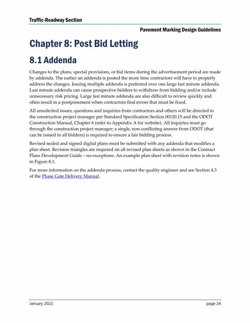
Revised sealed and signed digital plans must be submitted with any addenda that modifies a
plan sheet. Revision triangles are required on all revised plan sheets as shown in the Contract
Plans Development Guide – no exceptions. An example plan sheet with revision notes is shown
in Figure 8.1.
For more information on the addenda process, contact the quality engineer and see Section 4.3
of the Phase Gate Delivery Manual.
Traffic-Roadway Section
Pavement Marking Design Guidelines
January 2022 page 25
Figure 8.1: An Example Plan Sheet with Revision Notes
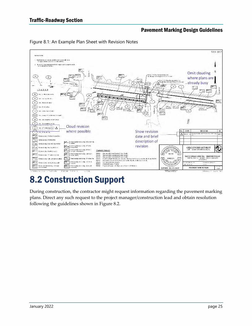
8.2 Construction Support During construction, the contractor might request information regarding the pavement marking
plans. Direct any such request to the project manager/construction lead and obtain resolution
following the guidelines shown in Figure 8.2.
Traffic-Roadway Section
Pavement Marking Design Guidelines
January 2022 page 26
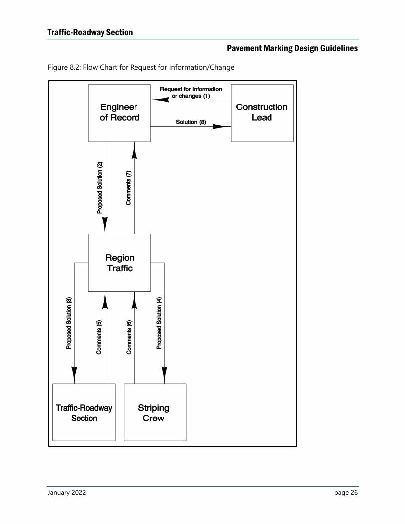
Figure 8.2: Flow Chart for Request for Information/Change
Traffic-Roadway Section
Pavement Marking Design Guidelines
January 2022 page 27
Boxes from Figure 8.2:
Construction lead – This is the ODOT designated construction lead. This could be a
project manager, consultant project manager (CPM), project leader, district permits, local
agency liaison, etc.
Engineer of record (EOR) – This is the person or firm that produced the pavement
marking plans. This could be ODOT, local agencies, consultants, etc. If the EOR is
unreachable, consult with the Traffic-Roadway Section for guidance.
Region Traffic – This is the ODOT region-based traffic office.
Traffic-Roadway Section – This is the ODOT Traffic-Roadway Section. The state traffic
engineer (STRE) leads this section.
Striping crew – These are the ODOT pavement marking crew managers for the specific
region.
Arrows from Figure 8.2
Request for information or changes (1) – This action includes the construction lead
submitting contractor questions, contractor proposals, errors in the plans and/or
specifications, etc. to the EOR for review and comment. For clarification of plans and/or
specifications, skip to STEP 8. For proposed changes to the plans and/or specifications,
continue to STEP 2.
Proposed solution (2) – This action includes the EOR submitting plans, specifications,
estimates, requests to deviate from standards, etc. to region traffic for review, comment,
and/or approval. For minor changes, skip to STEP 7. For major changes, continue to
STEP 3.
Proposed solution (3) – This action includes the region traffic submitting plans,
specifications, estimates, requests to deviate from standards, etc. to the Traffic-Roadway
Section for review, comment, and/or approval.
Proposed solution (4) – This action includes the region traffic submitting plans,
specifications, estimates, requests to deviate from standards, etc. to the pavement
marking crew for review, comment, and/or approval.
Comments (5) – This action includes the Traffic-Roadway Section approving, requesting
re-submittal, or rejecting the proposed solution to the region Traffic Section.
Comments (6) – This action includes the pavement marking crew approving, requesting
re-submittal, or rejecting the proposed solution to the region Traffic Section.
Comments (7) – This action includes the region Traffic Section approving, requesting re-
submittal, or rejecting the proposed solution to the EOR based on the Traffic-Roadway
Section and the pavement marking crew comments (for major changes). If the solution is
rejected, start over at STEP 2.
Solution (8) – This action includes the EOR submitting an approved solution to the
construction lead. The solution may include revised plan sheets, revised specifications,
and/or new plan sheets. The construction lead will then direct the contractor based on
the approved solution.
Traffic-Roadway Section
Pavement Marking Design Guidelines
January 2022 page 28
8.3 As-Constructed Plans The purpose of producing as-constructed contract plans is to accurately reflect the actual project
as it was constructed in the field. As-constructed plans can be a useful reference for future work
in the same area. For this reason, accuracy and clarity are important in the production of as-
constructed plans.
Producing as-constructed plans is necessary, because contract plans often change during
construction for various reasons.
The region construction office is responsible for marking-up contract plans to show how the
pavement markings were installed. Each plan sheet shall have a stamp “AS CONSTRUCTED”
along with signature of the project manager and date.
Example as-constructed plans are shown in Appendix D.
Units of measure will be maintained for all as-constructed plans.
Projects plans produced by consultants, developers or local agencies shall produce a complete
set of pavement marking plans, labeled and verified as as-constructed. Submit the as-
constructed plans to the region tech center.
Refer to Technical Bulletin TSB08-01(B), Chapter 12-H of the Construction Manual, and the
Contract Plans Development Guide for additional information related to the as-constructed
process.
ODOT designers:
Archive all CADD files used to create contract plan sheets after the project is let. Follow the
ProjectWise process for archiving CAD files.
Consultant designers:
Submit all CADD files used to create contract plan sheets to the region traffic office on CD/DVD
for archival after the project is let, if the project was not in ProjectWise. Otherwise follow the
ProjectWise process for archiving CAD files.
Traffic-Roadway Section
Pavement Marking Design Guidelines
January 2022 page 29
Chapter 9: Drafting Standards – General
9.1 Creating Pavement Marking Design Files Create at least two MicroStation files to produce contract plan sheets for pavement markings:
The pavement marking design file (base file): This file will contain the actual
pavement markings that will be installed or removed in the field, along with relevant
elements of the roadway design base map, such as centerline, edge of pavement,
median, curb line and so on.
The pavement marking plan sheet file: This file will contain the individual plan sheets,
bubble notes, legends and general notes. The pavement marking design file will be
referenced into the pavement marking plan sheet file.
Use additional files as needed or outlined in the Contract Plans Manual and the ProjectWise
User Manual and as necessary for your project needs.
Create a Pavement Marking Design File (Base File) Create a new file in MicroStation by right clicking in ProjectWise and selecting “New” then
“Document.” You may also open an existing file and create a new file from a 2D seed file. Name
the file according to the ProjectWise Document Name List and the Contract Plans Manual using
the ProjectWise file naming wizard. See section 9.2 for more information on file names
associated to pavement markings.
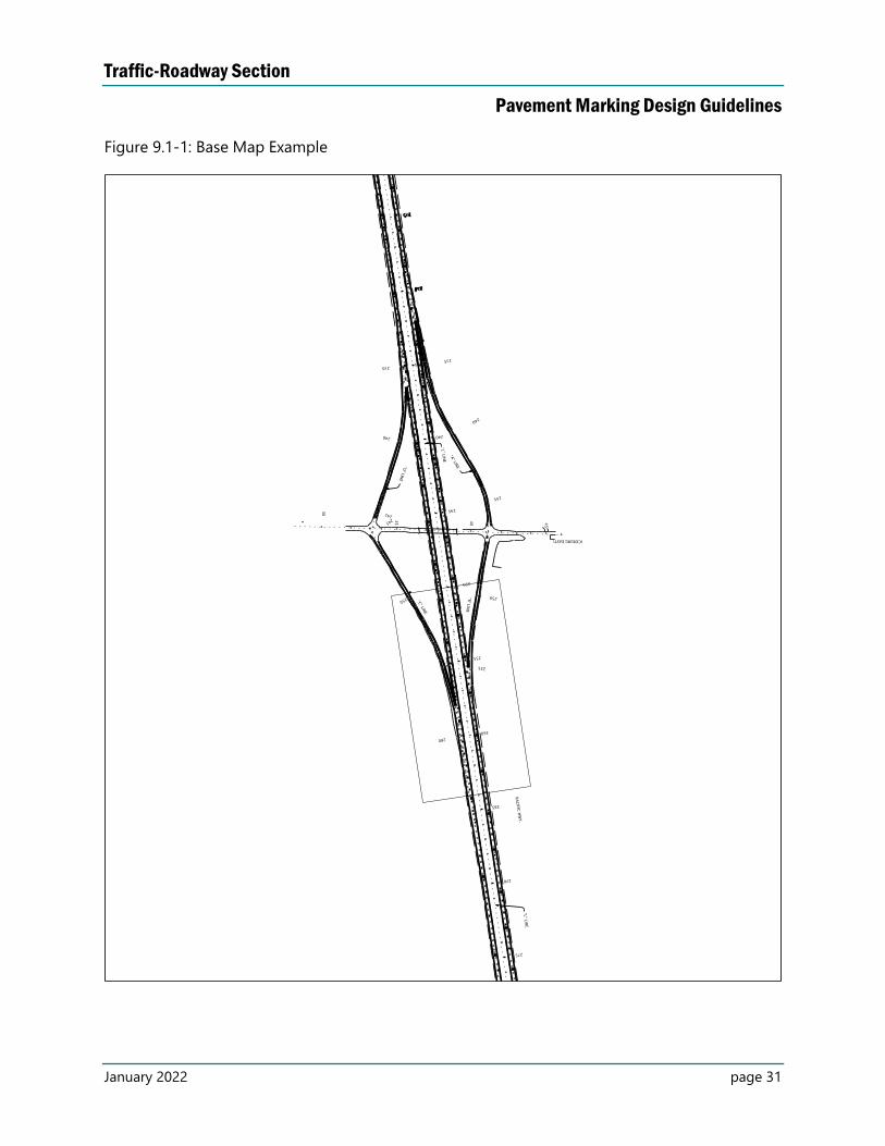
After referencing the survey and roadway base files, draw the pavement marking design
features into the file. Reference the signing and signal base files, as they become available, to
coordinate design of the overall project. Attach the base file to the plan sheet files, as a reference
file, to create contract plan sheets. Other designers will also use this file to attach to their plan
sheets (signing and signals).
Some designers begin their design using a working file, stored within their discipline folders.
This is true for pavement markings, as for other disciplines. The working files from related
disciplines may be available for reference prior to their conversion into base files, allowing for
greater coordination among the various discipline designers prior to DAP. Make sure to
reference the base file for plans and design for all project milestone submissions. Ensure the
base file includes all the design features in the working file.
Create a Pavement Marking Plan Sheet File Create a new 2D file that will be your pavement marking plan sheet file. Name the file as shown
in the ProjectWise Document Name List and the Contract Plans Manual using the ProjectWise
file naming wizard. See section 9.2 for more information on file names associated to pavement
markings. This file will contain all of the non-pavement marking features, such as the notes and
Traffic-Roadway Section
Pavement Marking Design Guidelines
January 2022 page 30
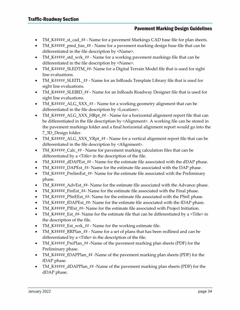
bubbles, borders, title block, and any other text needed for the contract plan sheets, as shown in
Figure 9.1-3. Figure 9.1-4 shows a plan sheet file with design file attached.
There are multiple ways to cut plan sheets either manually or using InRoads. Generally, as long
as there are roadway plan sheets, the easiest way to create the pavement marking plan sheets is
to reference the roadway sheet file into your new plan sheet file and select copy all attachments
in the nested references settings. From there, exchange references, as needed, for different base
files needed in the pavement marking plan sheet files.
Create Other Pavement Marking Files for Ease of Plans
Development You may create other files to ease plan development. For example, a CAD file containing
references with all the levels turned on and off, the way they will appear in the plan sheet, and
then with nested references not allowing overrides, to keep consistency in the plans.
You may also use a working file to develop various options or changes before copying and
adjusting pavement marking design in the base file.
Traffic-Roadway Section
Pavement Marking Design Guidelines
January 2022 page 31
Figure 9.1-1: Base Map Example
Traffic-Roadway Section
Pavement Marking Design Guidelines
January 2022 page 32
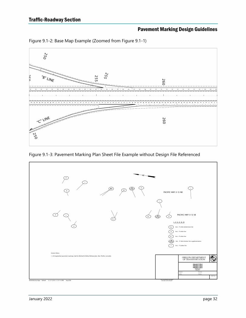
Figure 9.1-2: Base Map Example (Zoomed from Figure 9.1-1)
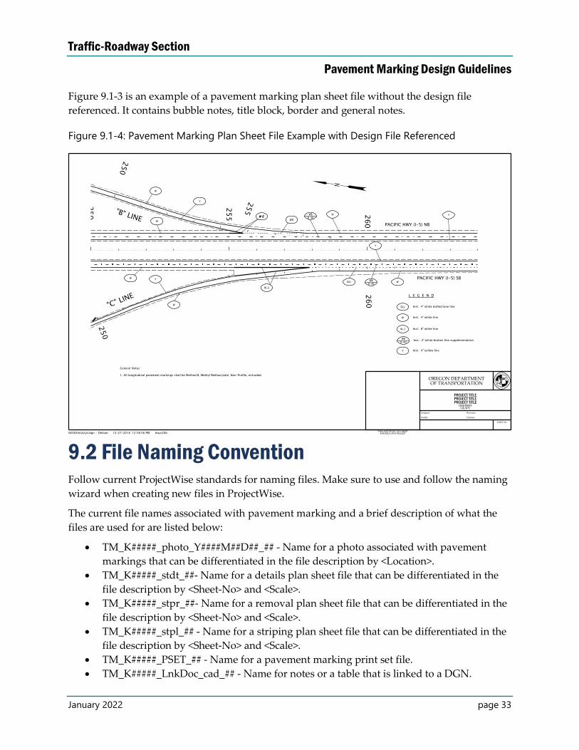
Figure 9.1-3: Pavement Marking Plan Sheet File Example without Design File Referenced
Traffic-Roadway Section
Pavement Marking Design Guidelines
January 2022 page 33
Figure 9.1-3 is an example of a pavement marking plan sheet file without the design file
referenced. It contains bubble notes, title block, border and general notes.
Figure 9.1-4: Pavement Marking Plan Sheet File Example with Design File Referenced
9.2 File Naming Convention Follow current ProjectWise standards for naming files. Make sure to use and follow the naming
wizard when creating new files in ProjectWise.
The current file names associated with pavement marking and a brief description of what the
files are used for are listed below:
TM_K#####_photo_Y####M##D##_## - Name for a photo associated with pavement
markings that can be differentiated in the file description by <Location>.
TM_K#####_stdt_##- Name for a details plan sheet file that can be differentiated in the
file description by <Sheet-No> and <Scale>.
TM_K#####_stpr_##- Name for a removal plan sheet file that can be differentiated in the
file description by <Sheet-No> and <Scale>.
TM_K#####_stpl_## - Name for a striping plan sheet file that can be differentiated in the
file description by <Sheet-No> and <Scale>.
TM_K#####_PSET_## - Name for a pavement marking print set file.
TM_K#####_LnkDoc_cad_## - Name for notes or a table that is linked to a DGN.
Traffic-Roadway Section
Pavement Marking Design Guidelines
January 2022 page 34
TM_K#####_st_cad_## - Name for a pavement Markings CAD base file for plan sheets.
TM_K#####_pmd_bas_## - Name for a pavement marking design base file that can be
differentiated in the file description by <Name>.
TM_K#####_std_wrk_## - Name for a working pavement markings file that can be
differentiated in the file description by <Name>.
TM_K#####_SLEDTM_##- Name for a Digital Terrain Model file that is used for sight
line evaluations.
TM_K#####_SLEITL_## - Name for an InRoads Template Library file that is used for
sight line evaluations.
TM_K#####_SLEIRD_## - Name for an InRoads Roadway Designer file that is used for
sight line evaluations.
TM_K#####_ALG_XXX_## - Name for a working geometry alignment that can be
differentiated in the file description by <Location>.
TM_K#####_ALG_XXX_HRpt_## - Name for a horizontal alignment report file that can
be differentiated in the file description by <Alignment>. A working file can be stored in
the pavement markings folder and a final horizontal alignment report would go into the
7_3D_Design folder.
TM_K#####_ALG_XXX_VRpt_## - Name for a vertical alignment report file that can be
differentiated in the file description by <Alignment>.
TM_K#####_Calc_## - Name for pavement marking calculation files that can be
differentiated by a <Title> in the description of the file.
TM_K#####_dDAPEst_## - Name for the estimate file associated with the dDAP phase.
TM_K#####_DAPEst_##- Name for the estimate file associated with the DAP phase.
TM_K#####_PrelimEst_##- Name for the estimate file associated with the Preliminary
phase.
TM_K#####_AdvEst_##- Name for the estimate file associated with the Advance phase.
TM_K#####_FinEst_##- Name for the estimate file associated with the Final phase.
TM_K#####_PSnEEst_##- Name for the estimate file associated with the PSnE phase.
TM_K#####_fDAPEst_##- Name for the estimate file associated with the fDAP phase.
TM_K#####_PIEst_##- Name for the estimate file associated with Project Initiation.
TM_K#####_Est_##- Name for the estimate file that can be differentiated by a <Title> in
the description of the file.
TM_K#####_Est_wrk_## - Name for the working estimate file.
TM_K#####_RRPlan_## - Name for a set of plans that has been redlined and can be
differentiated by a <Title> in the description of the file.
TM_K#####_PrePlan_## -Name of the pavement marking plan sheets (PDF) for the
Preliminary phase.
TM_K#####_fDAPPlan_## -Name of the pavement marking plan sheets (PDF) for the
fDAP phase.
TM_K#####_dDAPPlan_## -Name of the pavement marking plan sheets (PDF) for the
dDAP phase.
Traffic-Roadway Section
Pavement Marking Design Guidelines
January 2022 page 35
TM_K#####_DAPPlan _## -Name of the pavement marking plan sheets (PDF) for the
DAP phase.
TM_K#####_PIPlan_##-Name of the pavement marking plan sheets (PDF) for Project
Initiation.
TM_K#####_AdvPlan_## -Name of the pavement marking plan sheets (PDF) for the
Advance phase.
TM_K#####_FinPlan_## -Name of the pavement marking plan sheets (PDF) for the Final
phase.
TM_K#####_Plan_## - Name of the pavement marking plan sheets (PDF) that can be
differentiated by a <Title> in the description of the file.
TM_K#####_Q_## - Name for a quantity file that can be differentiated by a <Title> in the
description of the file.
TM_K#####_Misc_## - Name for a miscellaneous file that can be differentiated by a
<Title> in the description of the file.
There may be additional names in the pavement marking naming options that are not typically
associate with pavement marking files. These are rarely used and may be typically associated
to another discipline.
9.3 ODOT Pavement Marking Drafting Tool ODOT developed a drafting tool to aid in drafting and designing MicroStation files using
agency standards. A separate menu is available for the preparation of pavement marking plans
containing different longitudinal line types, along with reflectors and transverse markings (both
bars and legends). The tool also places bubble notes, legends and leaders, making the
development of the pavement marking plans more efficient. The drafting tool also places all
accessed items in the correct level, using correct color, weight and line style.
The striping ribbon can be accessed from ODOT Traffic Striping menu. Within the striping
ribbon, there are five striping tool options:
Long Lines: Contains different longitudinal line types used for pavement marking
design. It also contains a line style for longitudinal rumble strips.
Reflectors and Buttons: Contains cells for raised pavement markers with appropriate
spacing used for substitution and supplementation of pavement markings and for
vehicle positioning guide, as well. When these cells are used, it is not required to draw
separate lines with which reflectors are used.
Pavement Bars: Contains the cells for standard and wide stop bars. Use these to draw
standard crosswalks.
Pavement Legends: Contains cells for various transverse pavement marking legends,
such as arrows, bike markings, railroad markings etc.
Striping Notes: Used to detail pavement marking plans, such as placing bubbles with
leaders and texts. Figure 9.3 shows the Place Note Striping toolbox.
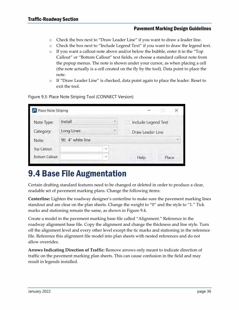
o Choose your note type, followed by category, and note.
Traffic-Roadway Section
Pavement Marking Design Guidelines
January 2022 page 36
o Check the box next to “Draw Leader Line” if you want to draw a leader line.
o Check the box next to “Include Legend Text” if you want to draw the legend text.
o If you want a callout note above and/or below the bubble, enter it in the “Top
Callout” or “Bottom Callout” text fields, or choose a standard callout note from
the popup menus. The note is shown under your cursor, as when placing a cell
(the note actually is a cell created on the fly by the tool). Data point to place the
note.
o If “Draw Leader Line” is checked, data point again to place the leader. Reset to
exit the tool.
Figure 9.3: Place Note Striping Tool (CONNECT Version)
9.4 Base File Augmentation Certain drafting standard features need to be changed or deleted in order to produce a clear,
readable set of pavement marking plans. Change the following items:
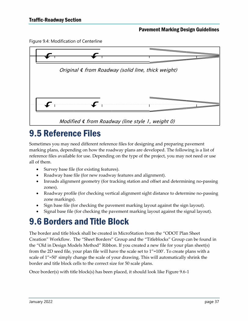
Centerline: Lighten the roadway designer’s centerline to make sure the pavement marking lines
standout and are clear on the plan sheets. Change the weight to “0” and the style to “1.” Tick
marks and stationing remain the same, as shown in Figure 9.4.
Create a model in the pavement marking base file called “Alignment.” Reference in the
roadway alignment base file. Copy the alignment and change the thickness and line style. Turn
off the alignment level and every other level except the tic marks and stationing in the reference
file. Reference this alignment file model into plan sheets with nested references and do not
allow overrides.
Arrows Indicating Direction of Traffic: Remove arrows only meant to indicate direction of
traffic on the pavement marking plan sheets. This can cause confusion in the field and may
result in legends installed.
Traffic-Roadway Section
Pavement Marking Design Guidelines
January 2022 page 37
Figure 9.4: Modification of Centerline
9.5 Reference Files Sometimes you may need different reference files for designing and preparing pavement
marking plans, depending on how the roadway plans are developed. The following is a list of
reference files available for use. Depending on the type of the project, you may not need or use
all of them.
Survey base file (for existing features).
Roadway base file (for new roadway features and alignment).
Inroads alignment geometry (for tracking station and offset and determining no-passing
zones).
Roadway profile (for checking vertical alignment sight distance to determine no-passing
zone markings).
Sign base file (for checking the pavement marking layout against the sign layout).
Signal base file (for checking the pavement marking layout against the signal layout).
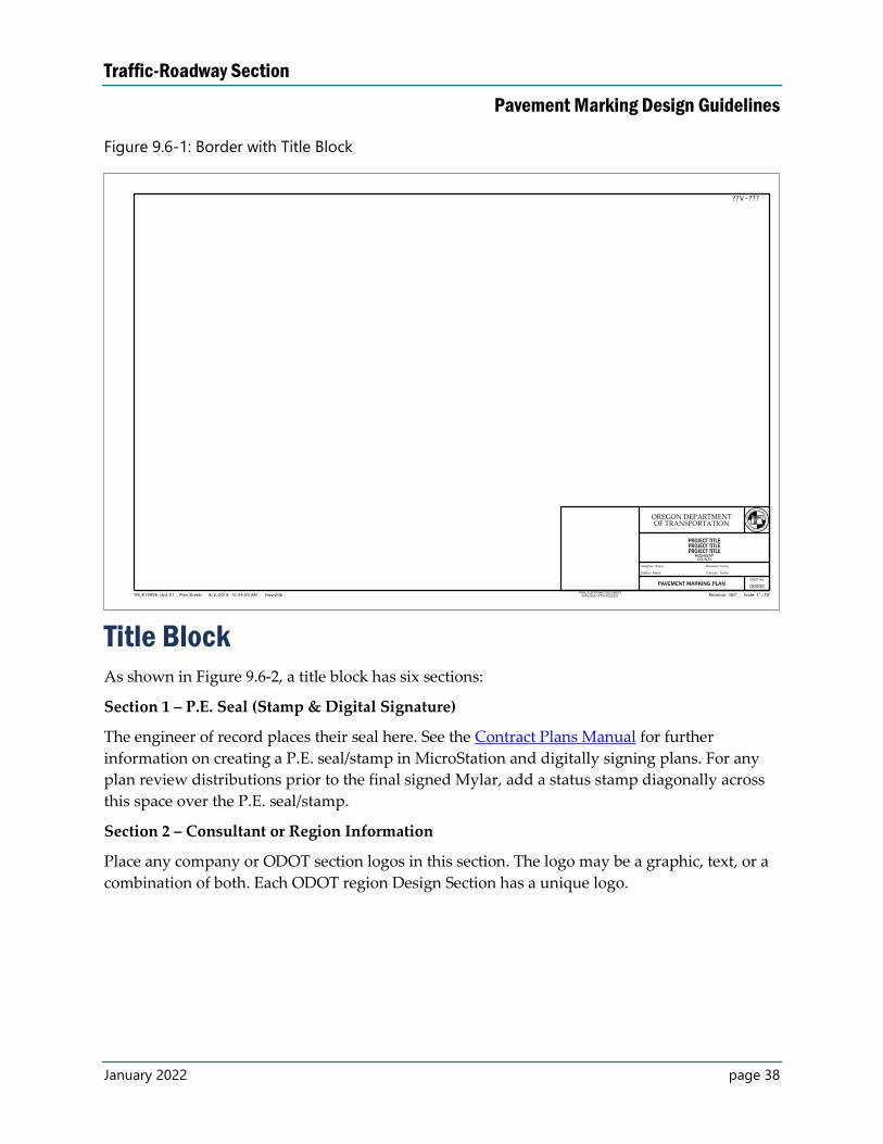
9.6 Borders and Title Block The border and title block shall be created in MicroStation from the “ODOT Plan Sheet
Creation” Workflow. The “Sheet Borders” Group and the “Titleblocks” Group can be found in
the “Old in Design Models Method” Ribbon. If you created a new file for your plan sheet(s)
from the 2D seed file, your plan file will have the scale set to 1”=100’. To create plans with a
scale of 1”=50’ simply change the scale of your drawing. This will automatically shrink the
border and title block cells to the correct size for 50 scale plans.
Once border(s) with title block(s) has been placed, it should look like Figure 9.6-1
Traffic-Roadway Section
Pavement Marking Design Guidelines
January 2022 page 38
Figure 9.6-1: Border with Title Block
Title Block As shown in Figure 9.6-2, a title block has six sections:
Section 1 – P.E. Seal (Stamp & Digital Signature)
The engineer of record places their seal here. See the Contract Plans Manual for further
information on creating a P.E. seal/stamp in MicroStation and digitally signing plans. For any
plan review distributions prior to the final signed Mylar, add a status stamp diagonally across
this space over the P.E. seal/stamp.
Section 2 – Consultant or Region Information
Place any company or ODOT section logos in this section. The logo may be a graphic, text, or a
combination of both. Each ODOT region Design Section has a unique logo.
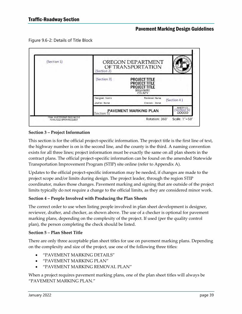
Traffic-Roadway Section
Pavement Marking Design Guidelines
January 2022 page 39
Figure 9.6-2: Details of Title Block
Section 3 – Project Information
This section is for the official project-specific information. The project title is the first line of text,
the highway number is on is the second line, and the county is the third. A naming convention
exists for all three lines; project information must be exactly the same on all plan sheets in the
contract plans. The official project-specific information can be found on the amended Statewide
Transportation Improvement Program (STIP) site online (refer to Appendix A).
Updates to the official project-specific information may be needed, if changes are made to the
project scope and/or limits during design. The project leader, through the region STIP
coordinator, makes those changes. Pavement marking and signing that are outside of the project
limits typically do not require a change to the official limits, as they are considered minor work.
Section 4 – People Involved with Producing the Plan Sheets
The correct order to use when listing people involved in plan sheet development is designer,
reviewer, drafter, and checker, as shown above. The use of a checker is optional for pavement
marking plans, depending on the complexity of the project. If used (per the quality control
plan), the person completing the check should be listed.
Section 5 – Plan Sheet Title
There are only three acceptable plan sheet titles for use on pavement marking plans. Depending
on the complexity and size of the project, use one of the following three titles:
“PAVEMENT MARKING DETAILS”
“PAVEMENT MARKING PLAN”
“PAVEMENT MARKING REMOVAL PLAN”
When a project requires pavement marking plans, one of the plan sheet titles will always be
“PAVEMENT MARKING PLAN.”
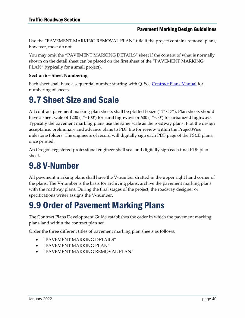
Traffic-Roadway Section
Pavement Marking Design Guidelines
January 2022 page 40
Use the “PAVEMENT MARKING REMOVAL PLAN” title if the project contains removal plans;
however, most do not.
You may omit the “PAVEMENT MARKING DETAILS” sheet if the content of what is normally
shown on the detail sheet can be placed on the first sheet of the “PAVEMENT MARKING
PLAN” (typically for a small project).
Section 6 – Sheet Numbering
Each sheet shall have a sequential number starting with Q. See Contract Plans Manual for
numbering of sheets.
9.7 Sheet Size and Scale All contract pavement marking plan sheets shall be plotted B size (11”x17”). Plan sheets should
have a sheet scale of 1200 (1”=100’) for rural highways or 600 (1”=50’) for urbanized highways.
Typically the pavement marking plans use the same scale as the roadway plans. Plot the design
acceptance, preliminary and advance plans to PDF file for review within the ProjectWise
milestone folders. The engineers of record will digitally sign each PDF page of the PS&E plans,
once printed.
An Oregon-registered professional engineer shall seal and digitally sign each final PDF plan
sheet.
9.8 V-Number All pavement marking plans shall have the V-number drafted in the upper right hand corner of
the plans. The V-number is the basis for archiving plans; archive the pavement marking plans
with the roadway plans. During the final stages of the project, the roadway designer or
specifications writer assigns the V-number.
9.9 Order of Pavement Marking Plans The Contract Plans Development Guide establishes the order in which the pavement marking
plans land within the contract plan set.
Order the three different titles of pavement marking plan sheets as follows:
“PAVEMENT MARKING DETAILS”
“PAVEMENT MARKING PLAN”
“PAVEMENT MARKING REMOVAL PLAN”
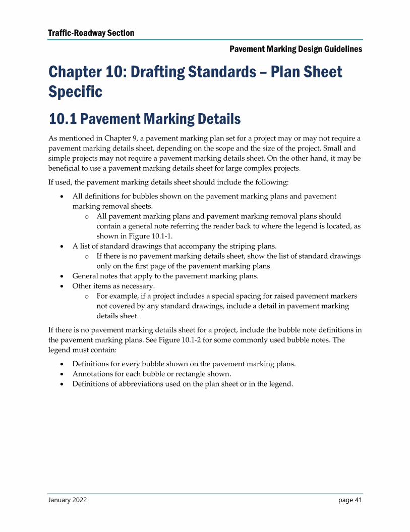
Traffic-Roadway Section
Pavement Marking Design Guidelines
January 2022 page 41
Chapter 10: Drafting Standards – Plan Sheet
Specific
10.1 Pavement Marking Details As mentioned in Chapter 9, a pavement marking plan set for a project may or may not require a
pavement marking details sheet, depending on the scope and the size of the project. Small and
simple projects may not require a pavement marking details sheet. On the other hand, it may be
beneficial to use a pavement marking details sheet for large complex projects.
If used, the pavement marking details sheet should include the following:
All definitions for bubbles shown on the pavement marking plans and pavement
marking removal sheets.
o All pavement marking plans and pavement marking removal plans should
contain a general note referring the reader back to where the legend is located, as
shown in Figure 10.1-1.
A list of standard drawings that accompany the striping plans.
o If there is no pavement marking details sheet, show the list of standard drawings
only on the first page of the pavement marking plans.
General notes that apply to the pavement marking plans.
Other items as necessary.
o For example, if a project includes a special spacing for raised pavement markers
not covered by any standard drawings, include a detail in pavement marking
details sheet.
If there is no pavement marking details sheet for a project, include the bubble note definitions in
the pavement marking plans. See Figure 10.1-2 for some commonly used bubble notes. The
legend must contain:
Definitions for every bubble shown on the pavement marking plans.
Annotations for each bubble or rectangle shown.
Definitions of abbreviations used on the plan sheet or in the legend.
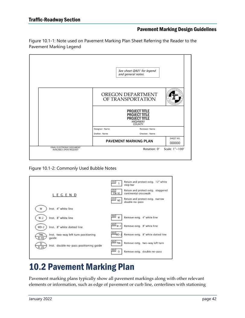
Traffic-Roadway Section
Pavement Marking Design Guidelines
January 2022 page 42
Figure 10.1-1: Note used on Pavement Marking Plan Sheet Referring the Reader to the
Pavement Marking Legend
Figure 10.1-2: Commonly Used Bubble Notes
10.2 Pavement Marking Plan Pavement marking plans typically show all pavement markings along with other relevant
elements or information, such as edge of pavement or curb line, centerlines with stationing
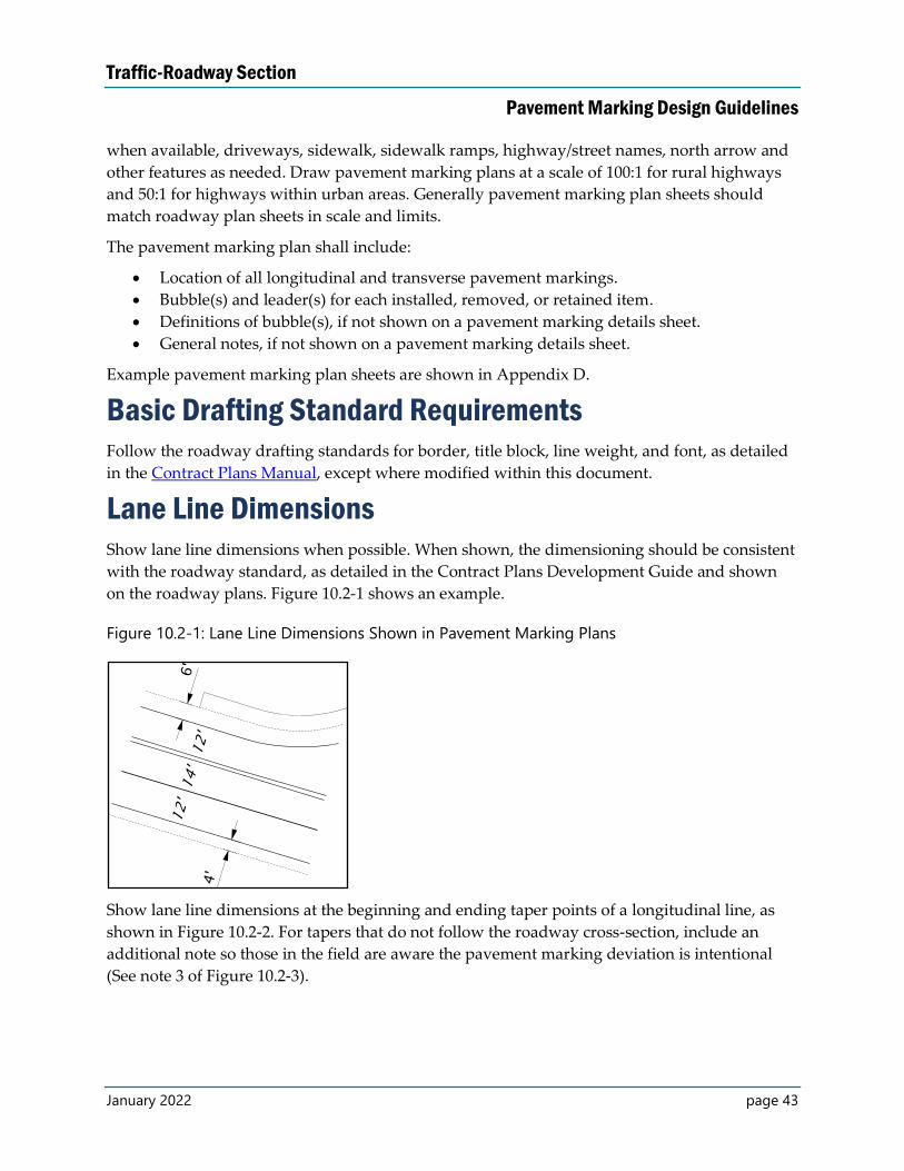
Traffic-Roadway Section
Pavement Marking Design Guidelines
January 2022 page 43
when available, driveways, sidewalk, sidewalk ramps, highway/street names, north arrow and
other features as needed. Draw pavement marking plans at a scale of 100:1 for rural highways
and 50:1 for highways within urban areas. Generally pavement marking plan sheets should
match roadway plan sheets in scale and limits.
The pavement marking plan shall include:
Location of all longitudinal and transverse pavement markings.
Bubble(s) and leader(s) for each installed, removed, or retained item.
Definitions of bubble(s), if not shown on a pavement marking details sheet.
General notes, if not shown on a pavement marking details sheet.
Example pavement marking plan sheets are shown in Appendix D.
Basic Drafting Standard Requirements Follow the roadway drafting standards for border, title block, line weight, and font, as detailed
in the Contract Plans Manual, except where modified within this document.
Lane Line Dimensions Show lane line dimensions when possible. When shown, the dimensioning should be consistent
with the roadway standard, as detailed in the Contract Plans Development Guide and shown
on the roadway plans. Figure 10.2-1 shows an example.
Figure 10.2-1: Lane Line Dimensions Shown in Pavement Marking Plans
Show lane line dimensions at the beginning and ending taper points of a longitudinal line, as
shown in Figure 10.2-2. For tapers that do not follow the roadway cross-section, include an
additional note so those in the field are aware the pavement marking deviation is intentional
(See note 3 of Figure 10.2-3).
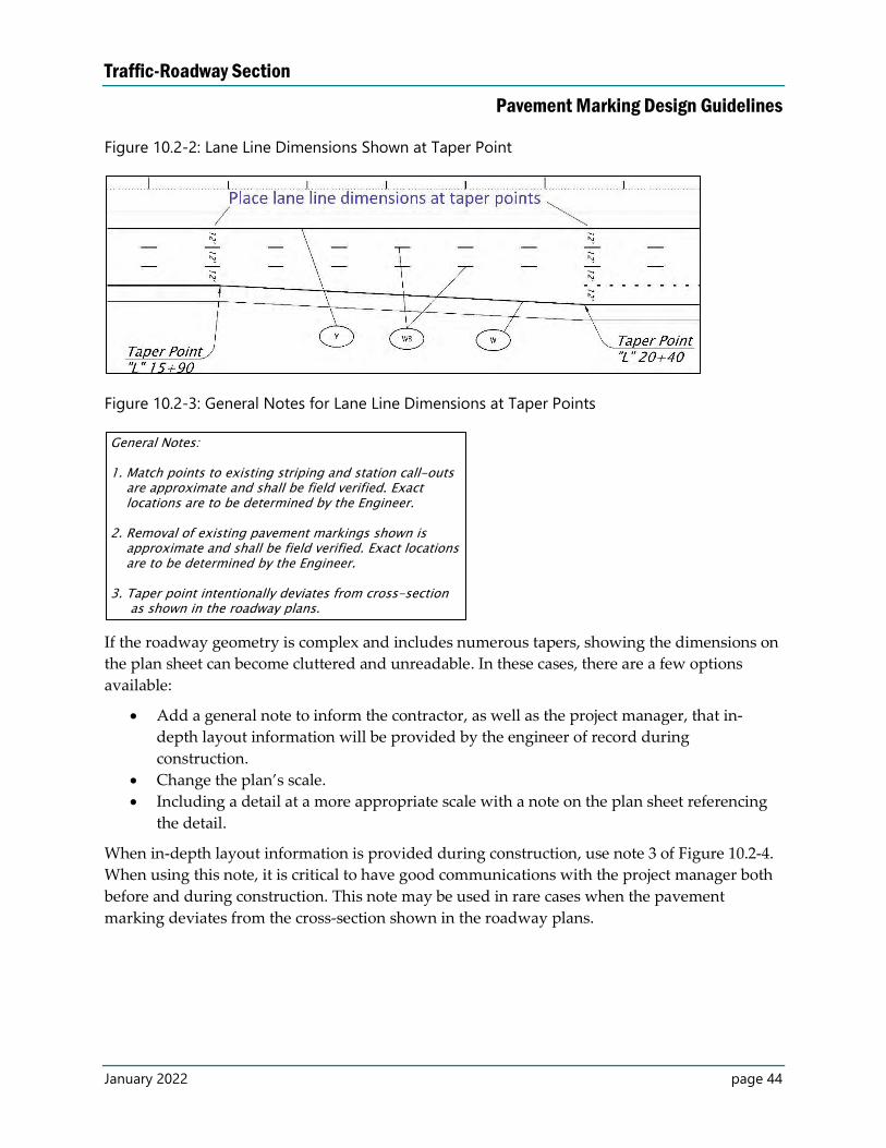
Traffic-Roadway Section
Pavement Marking Design Guidelines
January 2022 page 44
Figure 10.2-2: Lane Line Dimensions Shown at Taper Point
Figure 10.2-3: General Notes for Lane Line Dimensions at Taper Points
If the roadway geometry is complex and includes numerous tapers, showing the dimensions on
the plan sheet can become cluttered and unreadable. In these cases, there are a few options
available:
Add a general note to inform the contractor, as well as the project manager, that in-
depth layout information will be provided by the engineer of record during
construction.
Change the plan’s scale.
Including a detail at a more appropriate scale with a note on the plan sheet referencing
the detail.
When in-depth layout information is provided during construction, use note 3 of Figure 10.2-4.
When using this note, it is critical to have good communications with the project manager both
before and during construction. This note may be used in rare cases when the pavement
marking deviates from the cross-section shown in the roadway plans.
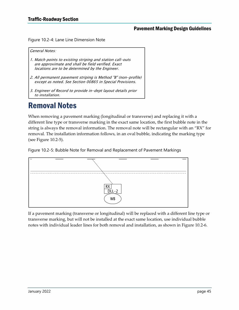
Traffic-Roadway Section
Pavement Marking Design Guidelines
January 2022 page 45
Figure 10.2-4: Lane Line Dimension Note
Removal Notes When removing a pavement marking (longitudinal or transverse) and replacing it with a
different line type or transverse marking in the exact same location, the first bubble note in the
string is always the removal information. The removal note will be rectangular with an “RX” for
removal. The installation information follows, in an oval bubble, indicating the marking type
(see Figure 10.2-5).
Figure 10.2-5: Bubble Note for Removal and Replacement of Pavement Markings
If a pavement marking (transverse or longitudinal) will be replaced with a different line type or
transverse marking, but will not be installed at the exact same location, use individual bubble
notes with individual leader lines for both removal and installation, as shown in Figure 10.2-6.
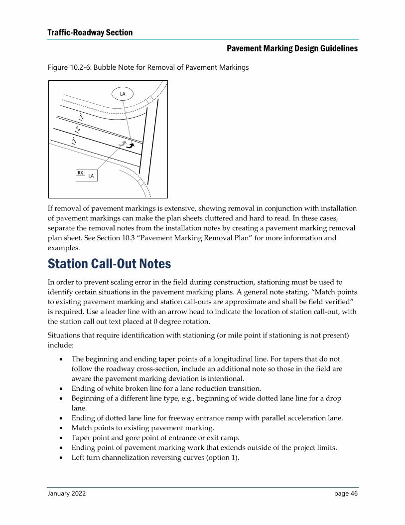
Traffic-Roadway Section
Pavement Marking Design Guidelines
January 2022 page 46
Figure 10.2-6: Bubble Note for Removal of Pavement Markings
If removal of pavement markings is extensive, showing removal in conjunction with installation
of pavement markings can make the plan sheets cluttered and hard to read. In these cases,
separate the removal notes from the installation notes by creating a pavement marking removal
plan sheet. See Section 10.3 “Pavement Marking Removal Plan” for more information and
examples.
Station Call-Out Notes In order to prevent scaling error in the field during construction, stationing must be used to
identify certain situations in the pavement marking plans. A general note stating, “Match points
to existing pavement marking and station call-outs are approximate and shall be field verified”
is required. Use a leader line with an arrow head to indicate the location of station call-out, with
the station call out text placed at 0 degree rotation.
Situations that require identification with stationing (or mile point if stationing is not present)
include:
The beginning and ending taper points of a longitudinal line. For tapers that do not
follow the roadway cross-section, include an additional note so those in the field are
aware the pavement marking deviation is intentional.
Ending of white broken line for a lane reduction transition.
Beginning of a different line type, e.g., beginning of wide dotted lane line for a drop
lane.
Ending of dotted lane line for freeway entrance ramp with parallel acceleration lane.
Match points to existing pavement marking.
Taper point and gore point of entrance or exit ramp.
Ending point of pavement marking work that extends outside of the project limits.
Left turn channelization reversing curves (option 1).
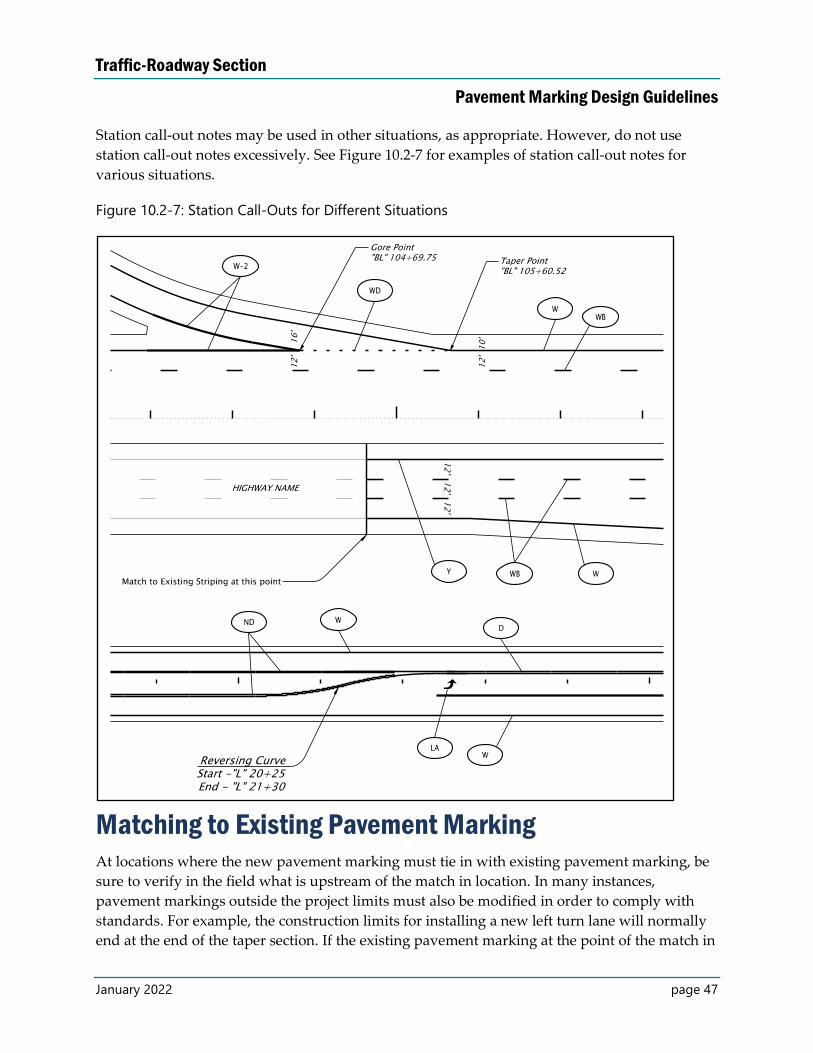
Traffic-Roadway Section
Pavement Marking Design Guidelines
January 2022 page 47
Station call-out notes may be used in other situations, as appropriate. However, do not use
station call-out notes excessively. See Figure 10.2-7 for examples of station call-out notes for
various situations.
Figure 10.2-7: Station Call-Outs for Different Situations
Matching to Existing Pavement Marking At locations where the new pavement marking must tie in with existing pavement marking, be
sure to verify in the field what is upstream of the match in location. In many instances,
pavement markings outside the project limits must also be modified in order to comply with
standards. For example, the construction limits for installing a new left turn lane will normally
end at the end of the taper section. If the existing pavement marking at the point of the match in
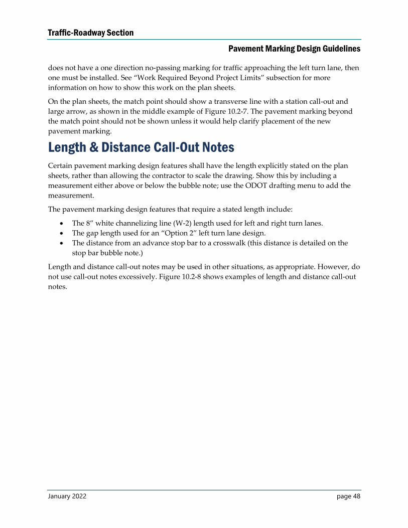
Traffic-Roadway Section
Pavement Marking Design Guidelines
January 2022 page 48
does not have a one direction no-passing marking for traffic approaching the left turn lane, then
one must be installed. See “Work Required Beyond Project Limits” subsection for more
information on how to show this work on the plan sheets.
On the plan sheets, the match point should show a transverse line with a station call-out and
large arrow, as shown in the middle example of Figure 10.2-7. The pavement marking beyond
the match point should not be shown unless it would help clarify placement of the new
pavement marking.
Length & Distance Call-Out Notes Certain pavement marking design features shall have the length explicitly stated on the plan
sheets, rather than allowing the contractor to scale the drawing. Show this by including a
measurement either above or below the bubble note; use the ODOT drafting menu to add the
measurement.
The pavement marking design features that require a stated length include:
The 8” white channelizing line (W-2) length used for left and right turn lanes.
The gap length used for an “Option 2” left turn lane design.
The distance from an advance stop bar to a crosswalk (this distance is detailed on the
stop bar bubble note.)
Length and distance call-out notes may be used in other situations, as appropriate. However, do
not use call-out notes excessively. Figure 10.2-8 shows examples of length and distance call-out
notes.
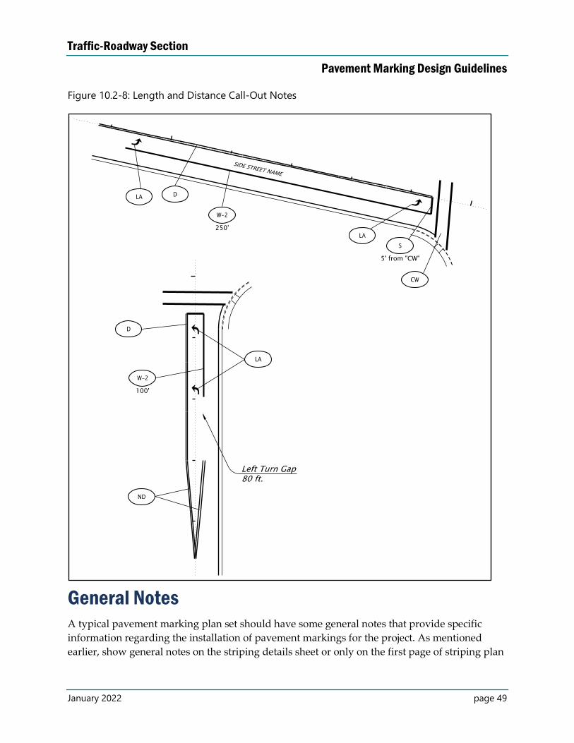
Traffic-Roadway Section
Pavement Marking Design Guidelines
January 2022 page 49
Figure 10.2-8: Length and Distance Call-Out Notes
General Notes A typical pavement marking plan set should have some general notes that provide specific
information regarding the installation of pavement markings for the project. As mentioned
earlier, show general notes on the striping details sheet or only on the first page of striping plan
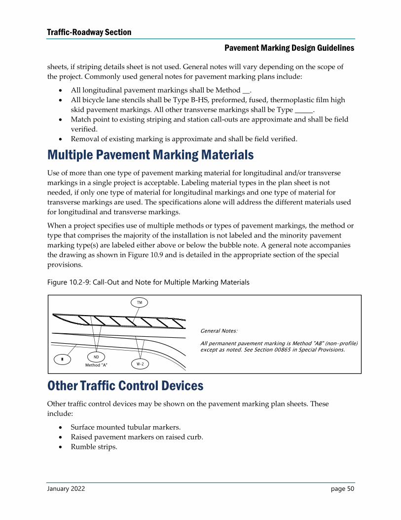
Traffic-Roadway Section
Pavement Marking Design Guidelines
January 2022 page 50
sheets, if striping details sheet is not used. General notes will vary depending on the scope of
the project. Commonly used general notes for pavement marking plans include:
All longitudinal pavement markings shall be Method __.
All bicycle lane stencils shall be Type B-HS, preformed, fused, thermoplastic film high
skid pavement markings. All other transverse markings shall be Type _____.
Match point to existing striping and station call-outs are approximate and shall be field
verified.
Removal of existing marking is approximate and shall be field verified.
Multiple Pavement Marking Materials Use of more than one type of pavement marking material for longitudinal and/or transverse
markings in a single project is acceptable. Labeling material types in the plan sheet is not
needed, if only one type of material for longitudinal markings and one type of material for
transverse markings are used. The specifications alone will address the different materials used
for longitudinal and transverse markings.
When a project specifies use of multiple methods or types of pavement markings, the method or
type that comprises the majority of the installation is not labeled and the minority pavement
marking type(s) are labeled either above or below the bubble note. A general note accompanies
the drawing as shown in Figure 10.9 and is detailed in the appropriate section of the special
provisions.
Figure 10.2-9: Call-Out and Note for Multiple Marking Materials
Other Traffic Control Devices Other traffic control devices may be shown on the pavement marking plan sheets. These
include:
Surface mounted tubular markers.
Raised pavement markers on raised curb.
Rumble strips.
Traffic-Roadway Section
Pavement Marking Design Guidelines
January 2022 page 51
Cells for these devices are available from the ODOT Drafting menu. However, no standard
bubble note is available. Designers need to include callouts for these items whenever present,
with appropriate spacing/type, as shown in Figure 10.10. Be aware that rumble strips shown in
plans may make the plans too busy and are normally shown in details rather than plan sheets.
Figure 10.2-10: Call-Out for Other Traffic Control Devices
Work Required Beyond Project Limits “Match existing pavement marking” with brackets is typically used to indicate the paving
limits. However, it may be necessary to change some or all of the existing pavement markings
outside of the paving limits. When work extends outside of the project limits, label any striping
to be modified outside of the paving limits with approximate beginning and ending stationing.
Include any applicable contractor directions, such as “remove existing pavement marking
before installing new pavement marking.”
Only show the existing pavement marking located outside the project limits, if it is necessary to
clarify placement of the new pavement marking (and use hatching), otherwise leave it out, as
shown in Figure 10.2-11. The first example shows the standard way to show work beyond
project limits. The second example shows the alternate way to show work beyond project limits
with hatching.
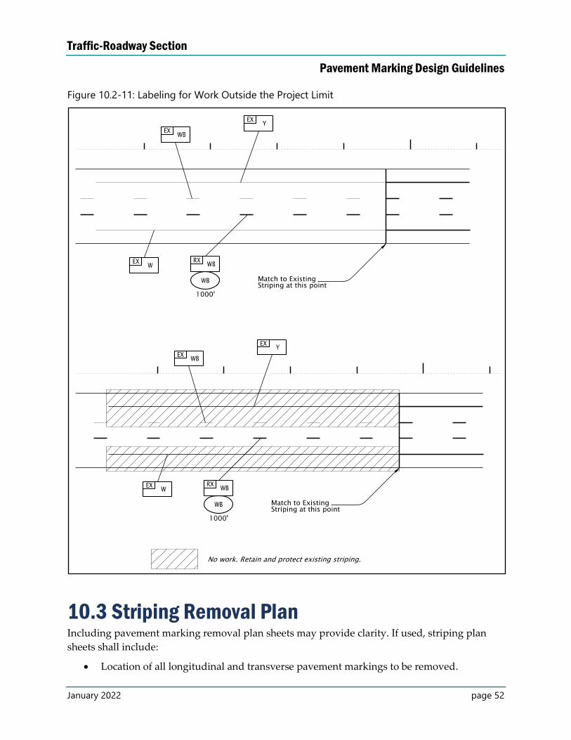
Traffic-Roadway Section
Pavement Marking Design Guidelines
January 2022 page 52
Figure 10.2-11: Labeling for Work Outside the Project Limit
10.3 Striping Removal Plan Including pavement marking removal plan sheets may provide clarity. If used, striping plan
sheets shall include:
Location of all longitudinal and transverse pavement markings to be removed.
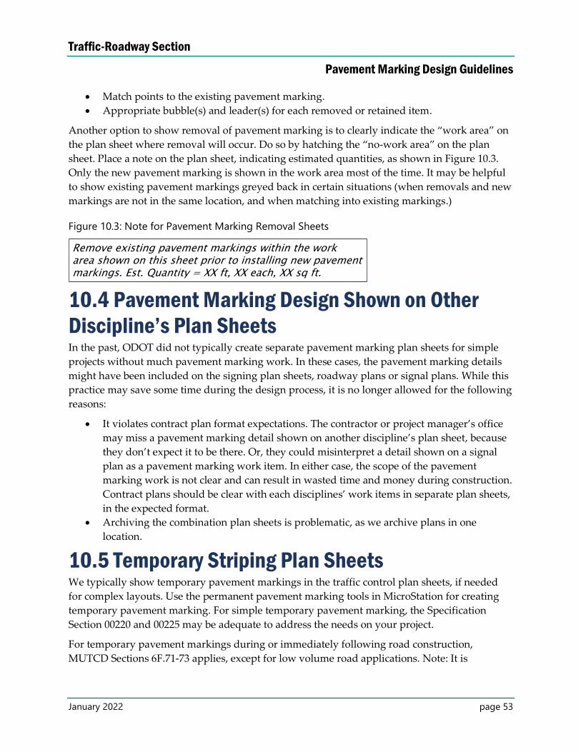
Traffic-Roadway Section
Pavement Marking Design Guidelines
January 2022 page 53
Match points to the existing pavement marking.
Appropriate bubble(s) and leader(s) for each removed or retained item.
Another option to show removal of pavement marking is to clearly indicate the “work area” on
the plan sheet where removal will occur. Do so by hatching the “no-work area” on the plan
sheet. Place a note on the plan sheet, indicating estimated quantities, as shown in Figure 10.3.
Only the new pavement marking is shown in the work area most of the time. It may be helpful
to show existing pavement markings greyed back in certain situations (when removals and new
markings are not in the same location, and when matching into existing markings.)
Figure 10.3: Note for Pavement Marking Removal Sheets
10.4 Pavement Marking Design Shown on Other
Discipline’s Plan Sheets In the past, ODOT did not typically create separate pavement marking plan sheets for simple
projects without much pavement marking work. In these cases, the pavement marking details
might have been included on the signing plan sheets, roadway plans or signal plans. While this
practice may save some time during the design process, it is no longer allowed for the following
reasons:
It violates contract plan format expectations. The contractor or project manager’s office
may miss a pavement marking detail shown on another discipline’s plan sheet, because
they don’t expect it to be there. Or, they could misinterpret a detail shown on a signal
plan as a pavement marking work item. In either case, the scope of the pavement
marking work is not clear and can result in wasted time and money during construction.
Contract plans should be clear with each disciplines’ work items in separate plan sheets,
in the expected format.
Archiving the combination plan sheets is problematic, as we archive plans in one
location.
10.5 Temporary Striping Plan Sheets We typically show temporary pavement markings in the traffic control plan sheets, if needed
for complex layouts. Use the permanent pavement marking tools in MicroStation for creating
temporary pavement marking. For simple temporary pavement marking, the Specification
Section 00220 and 00225 may be adequate to address the needs on your project.
For temporary pavement markings during or immediately following road construction,
MUTCD Sections 6F.71-73 applies, except for low volume road applications. Note: It is
Traffic-Roadway Section
Pavement Marking Design Guidelines
January 2022 page 54
allowable to indicate no-passing zones with signs only for periods of up to three days. Edge
lines are normally not marked in temporary applications.
See the Traffic Control Plans Design Manual for more information about how to show
temporary pavement marking in contract plans.
Traffic-Roadway Section
Pavement Marking Design Guidelines
January 2022 page 55
Appendix A – References
1. ODOT Pavement Marking Web Page:
https://www.oregon.gov/odot/Engineering/Pages/Striping.aspx
2. ODOT Traffic Line Manual:
https://www.oregon.gov/odot/Engineering/Documents_TrafficStandards/Traffic-Line-
Manual.pdf
3. Standard Drawings and Standard Details:
https://www.oregon.gov/odot/Engineering/Pages/Standards.aspx
4. ODOT Traffic Manual:
https://www.oregon.gov/odot/Engineering/Docs_TrafficEng/Traffic-Manual-2020.pdf
5. ODOT Standard Specifications:
https://www.oregon.gov/odot/Business/Pages/Standard_Specifications.aspx
6. Boilerplate Special Provisions:
https://www.oregon.gov/odot/Business/Pages/Standard_Specifications.aspx
7. Technical Guidance: https://www.oregon.gov/odot/Engineering/Pages/Technical-
Guidance.aspx
8. Railroad Crossing Order – call Rail Crossing Safety Manager at 503-986-4273.
9. Contract Plans Development Guide:
https://www.oregon.gov/odot/Engineering/Pages/CP-Development-Guide.aspx
10. ODOT Official Bid Item List:
https://www.oregon.gov/odot/Business/Pages/Standard_Specifications.aspx
11. ODOT Average Bid Item Prices:
https://www.oregon.gov/odot/Business/Pages/average_bid_item_prices.aspx
12. STIP Web Page: https://www.oregon.gov/odot/STIP/Pages/index.aspx
13. Microstation Workspace Download page (for consultants):
ftp://ftp.odot.state.or.us/isb/appeng/MicroStation/V8i/
14. Specification Technical Resource List:
https://www.oregon.gov/odot/Business/Specs/technical_resource_list.pdf
15. Traffic Control Plans Design Manual:
https://www.oregon.gov/odot/Engineering/Pages/TCP-Manual.aspx
16. Manual on Uniform Traffic Control Devices:
https://www.oregon.gov/odot/Construction/Pages/Construction-Manual.aspx
17. Construction Manual: https://www.oregon.gov/odot/Construction/Pages/Construction-
Manual.aspx
18. Phase Gate Delivery Manual:
https://www.oregon.gov/odot/Business/PCOManuals/Phase-Gate-Delivery-Manual.pdf
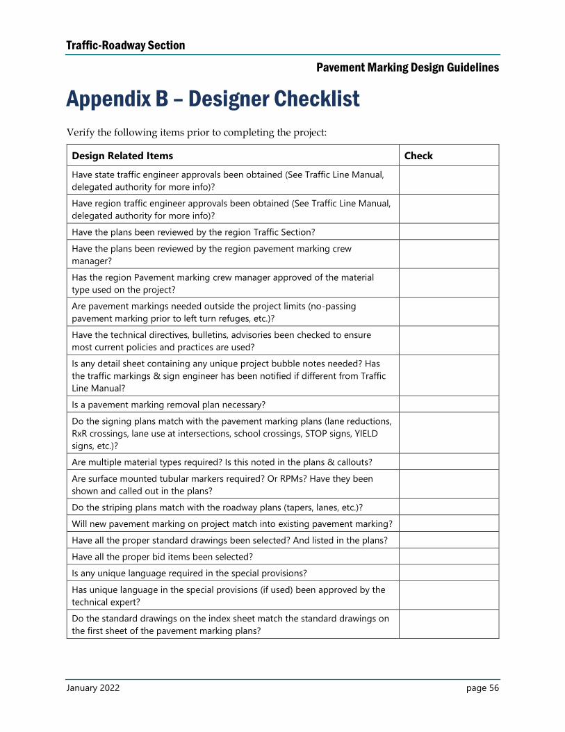
Traffic-Roadway Section
Pavement Marking Design Guidelines
January 2022 page 56
Appendix B – Designer Checklist
Verify the following items prior to completing the project:
Design Related Items Check
Have state traffic engineer approvals been obtained (See Traffic Line Manual,
delegated authority for more info)?
Have region traffic engineer approvals been obtained (See Traffic Line Manual,
delegated authority for more info)?
Have the plans been reviewed by the region Traffic Section?
Have the plans been reviewed by the region pavement marking crew
manager?
Has the region Pavement marking crew manager approved of the material
type used on the project?
Are pavement markings needed outside the project limits (no-passing
pavement marking prior to left turn refuges, etc.)?
Have the technical directives, bulletins, advisories been checked to ensure
most current policies and practices are used?
Is any detail sheet containing any unique project bubble notes needed? Has
the traffic markings & sign engineer has been notified if different from Traffic
Line Manual?
Is a pavement marking removal plan necessary?
Do the signing plans match with the pavement marking plans (lane reductions,
RxR crossings, lane use at intersections, school crossings, STOP signs, YIELD
signs, etc.)?
Are multiple material types required? Is this noted in the plans & callouts?
Are surface mounted tubular markers required? Or RPMs? Have they been
shown and called out in the plans?
Do the striping plans match with the roadway plans (tapers, lanes, etc.)?
Will new pavement marking on project match into existing pavement marking?
Have all the proper standard drawings been selected? And listed in the plans?
Have all the proper bid items been selected?
Is any unique language required in the special provisions?
Has unique language in the special provisions (if used) been approved by the
technical expert?
Do the standard drawings on the index sheet match the standard drawings on
the first sheet of the pavement marking plans?
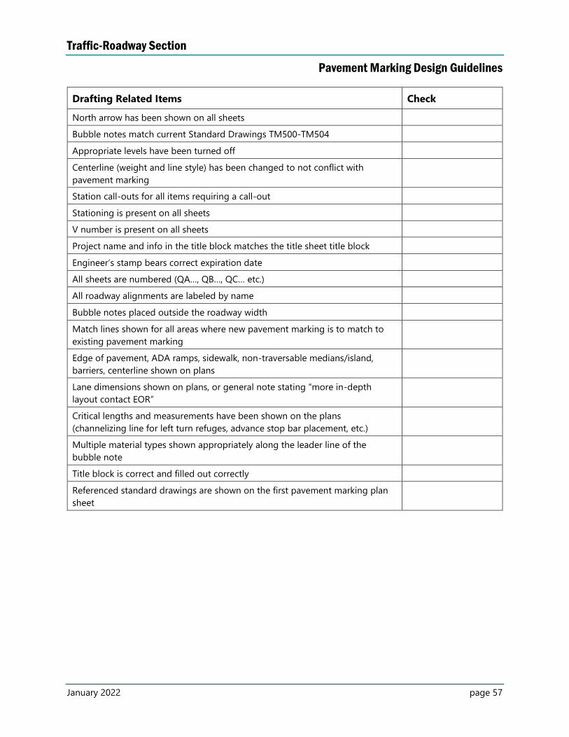
Traffic-Roadway Section
Pavement Marking Design Guidelines
January 2022 page 57
Drafting Related Items Check
North arrow has been shown on all sheets
Bubble notes match current Standard Drawings TM500-TM504
Appropriate levels have been turned off
Centerline (weight and line style) has been changed to not conflict with
pavement marking
Station call-outs for all items requiring a call-out
Stationing is present on all sheets
V number is present on all sheets
Project name and info in the title block matches the title sheet title block
Engineer’s stamp bears correct expiration date
All sheets are numbered (QA…, QB…, QC… etc.)
All roadway alignments are labeled by name
Bubble notes placed outside the roadway width
Match lines shown for all areas where new pavement marking is to match to
existing pavement marking
Edge of pavement, ADA ramps, sidewalk, non-traversable medians/island,
barriers, centerline shown on plans
Lane dimensions shown on plans, or general note stating “more in-depth
layout contact EOR”
Critical lengths and measurements have been shown on the plans
(channelizing line for left turn refuges, advance stop bar placement, etc.)
Multiple material types shown appropriately along the leader line of the
bubble note
Title block is correct and filled out correctly
Referenced standard drawings are shown on the first pavement marking plan
sheet
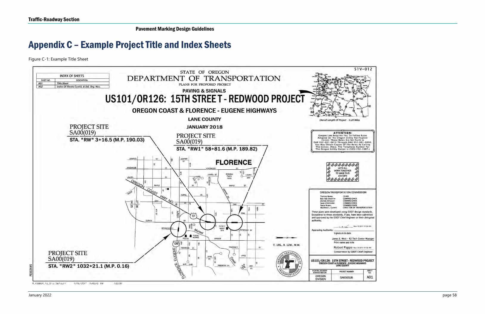
Traffic-Roadway Section
Pavement Marking Design Guidelines
January 2022 page 58
Appendix C – Example Project Title and Index Sheets
Figure C-1: Example Title Sheet
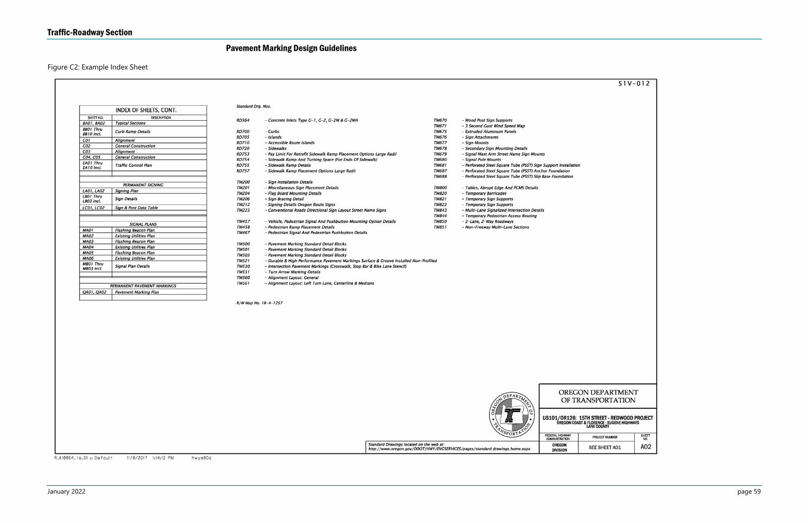
Traffic-Roadway Section
Pavement Marking Design Guidelines
January 2022 page 59
Figure C2: Example Index Sheet

Traffic-Roadway Section
Pavement Marking Design Guidelines
January 2022 page 60
Appendix D – Example As-Constructed Plans
Figure D-1: Example As-Constructed Plan Sheet (1)
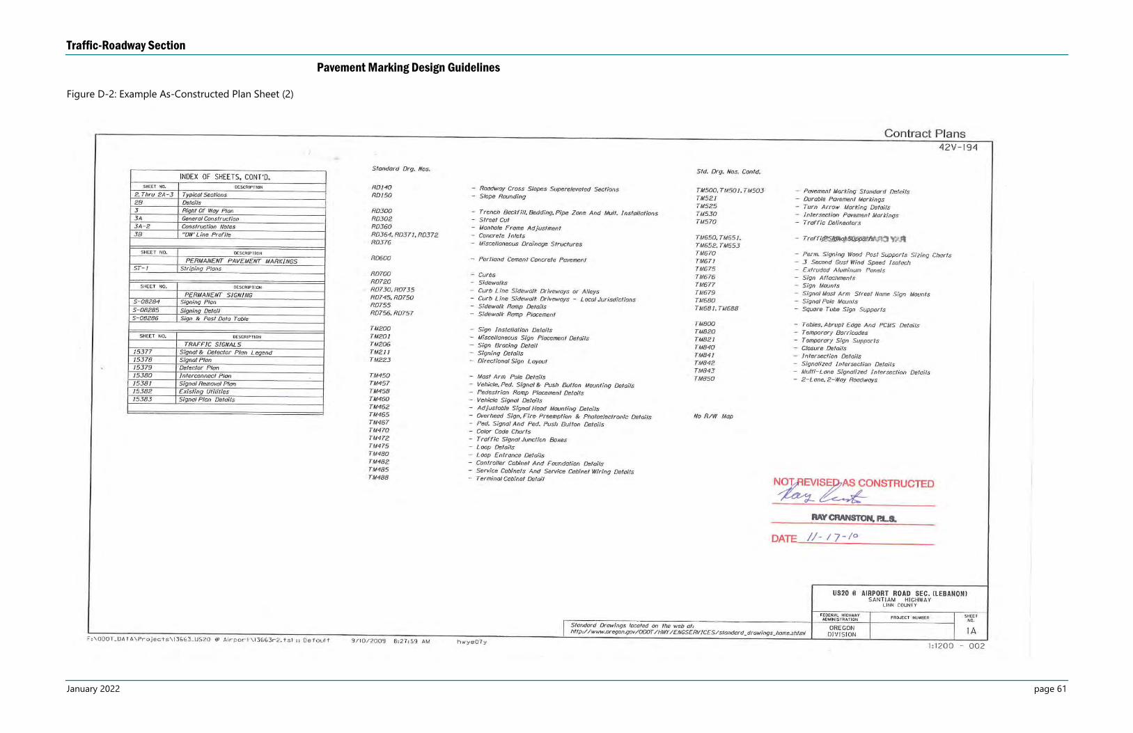
Traffic-Roadway Section
Pavement Marking Design Guidelines
January 2022 page 61
Figure D-2: Example As-Constructed Plan Sheet (2)
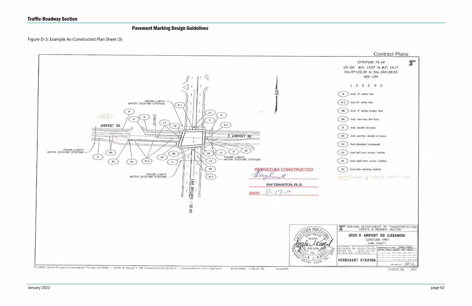
Traffic-Roadway Section
Pavement Marking Design Guidelines
January 2022 page 62
Figure D-3: Example As-Constructed Plan Sheet (3)
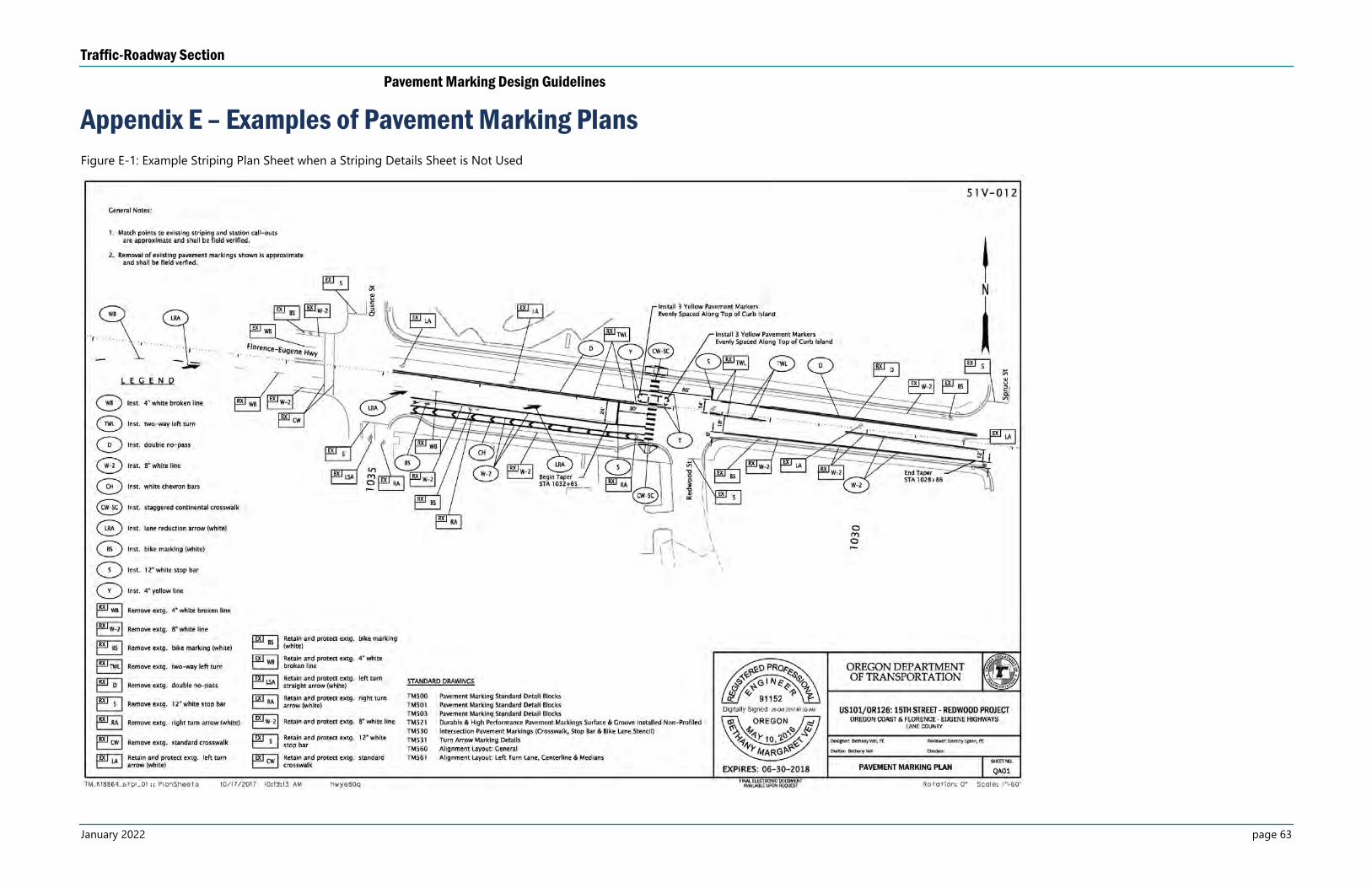
Traffic-Roadway Section
Pavement Marking Design Guidelines
January 2022 page 63
Appendix E – Examples of Pavement Marking Plans
Figure E-1: Example Striping Plan Sheet when a Striping Details Sheet is Not Used
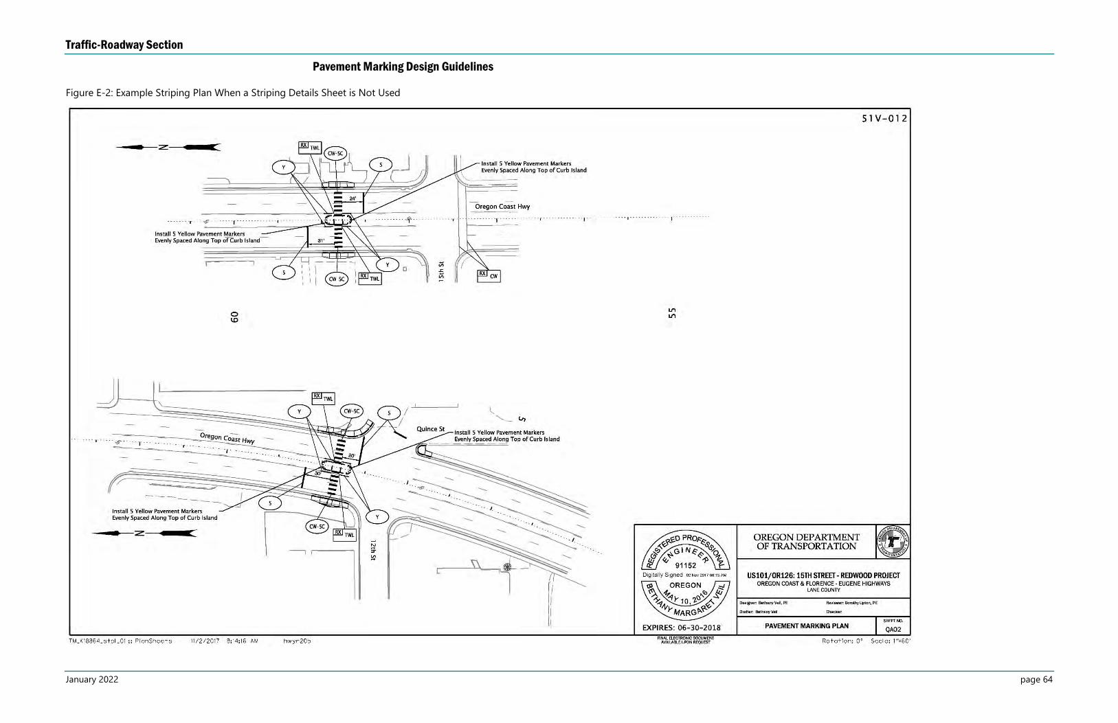
Traffic-Roadway Section
Pavement Marking Design Guidelines
January 2022 page 64
Figure E-2: Example Striping Plan When a Striping Details Sheet is Not Used
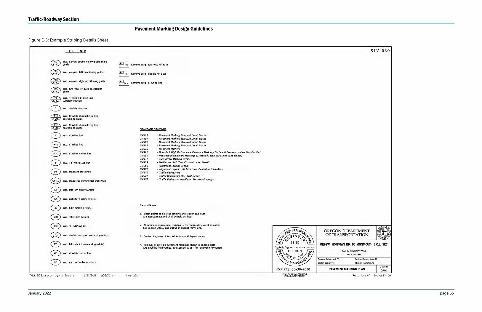
Traffic-Roadway Section
Pavement Marking Design Guidelines
January 2022 page 65
Figure E-3: Example Striping Details Sheet
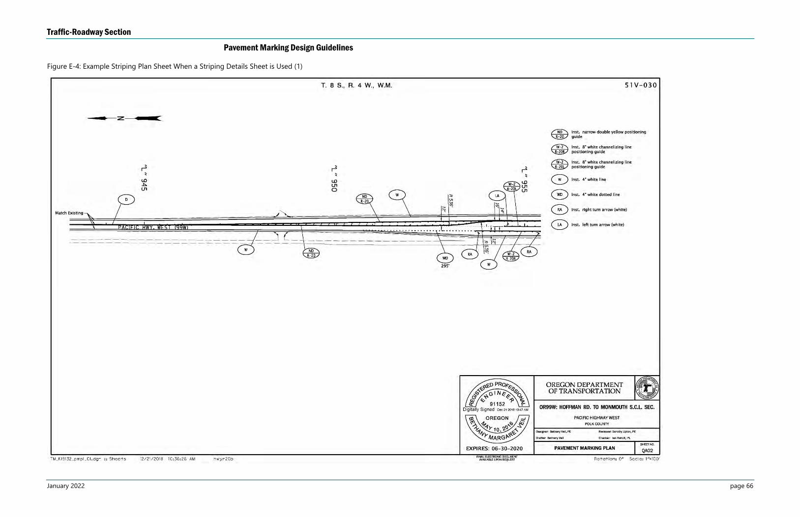
Traffic-Roadway Section
Pavement Marking Design Guidelines
January 2022 page 66
Figure E-4: Example Striping Plan Sheet When a Striping Details Sheet is Used (1)
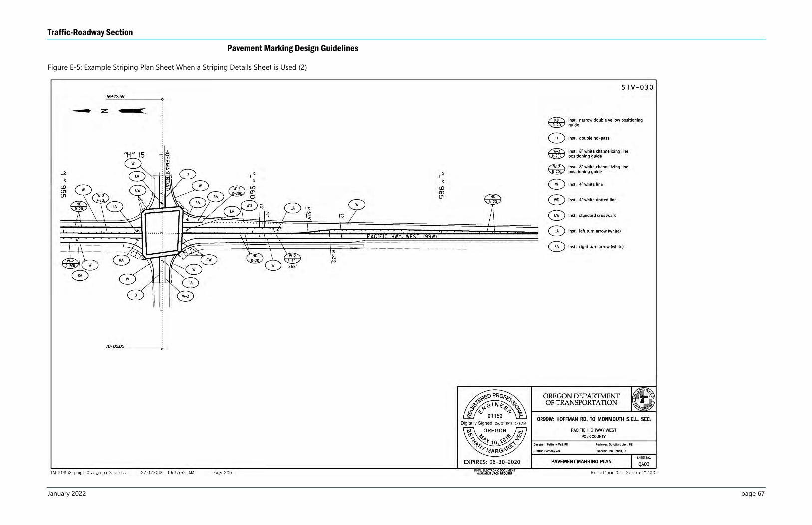
Traffic-Roadway Section
Pavement Marking Design Guidelines
January 2022 page 67
Figure E-5: Example Striping Plan Sheet When a Striping Details Sheet is Used (2)


