TECHNICAL NOTES on Brick Construction12007 Sunrise Valley Drive, Suite 430, Reston, Virginia 20191 | www.gobrick.com | 703-620-0010
14May 2017
Paving Systems Using Clay PaversAbstract: This Technical Note presents an overview of paving systems made with clay pavers used in pedestrian and vehicular, residential and nonresidential projects. Commonly used systems that include clay pavers are discussed, and guidance is given in selecting the appropriate clay paver, setting bed and base. Site conditions and project requirements that may affect choice are discussed, including subgrade soil, pedestrian and vehicular traffic, accessibility requirements, drainage and appearance.
• For information on permeable clay brick pavements, including design, construction, maintenance, stormwater management and environmental protection, refer to Technical Note 14D
• For guidance related to the accessibility of clay brick pavements to accommodate many types of traffic, including pedestrians with physical disabilities, refer to Technical Note 14E
• Use a design professional as necessary to verify suitability of a paving system design
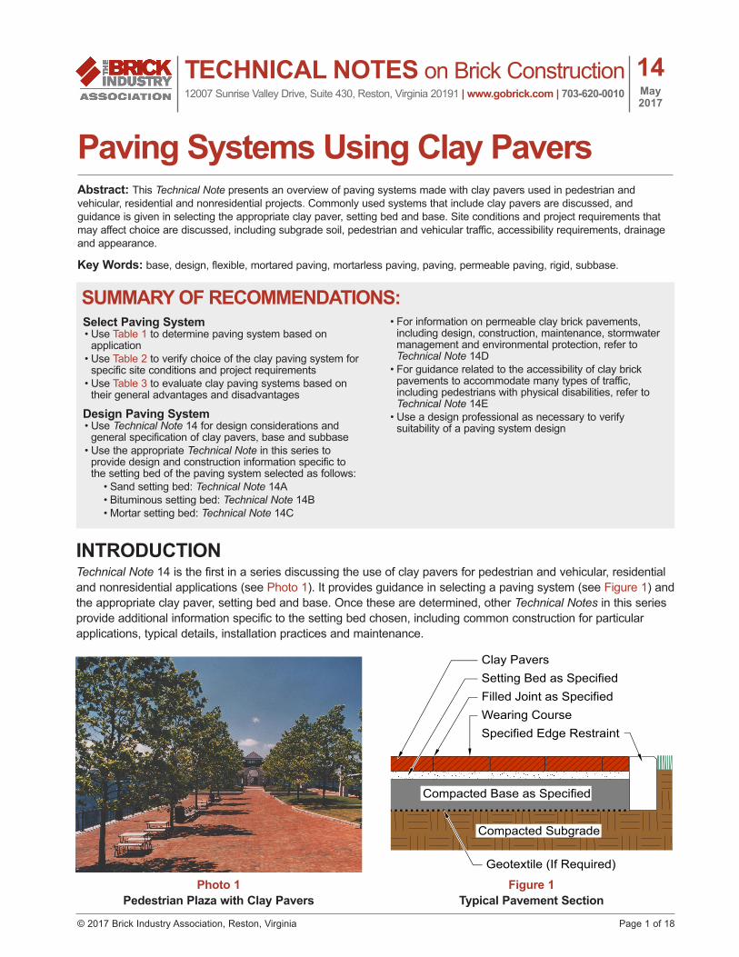
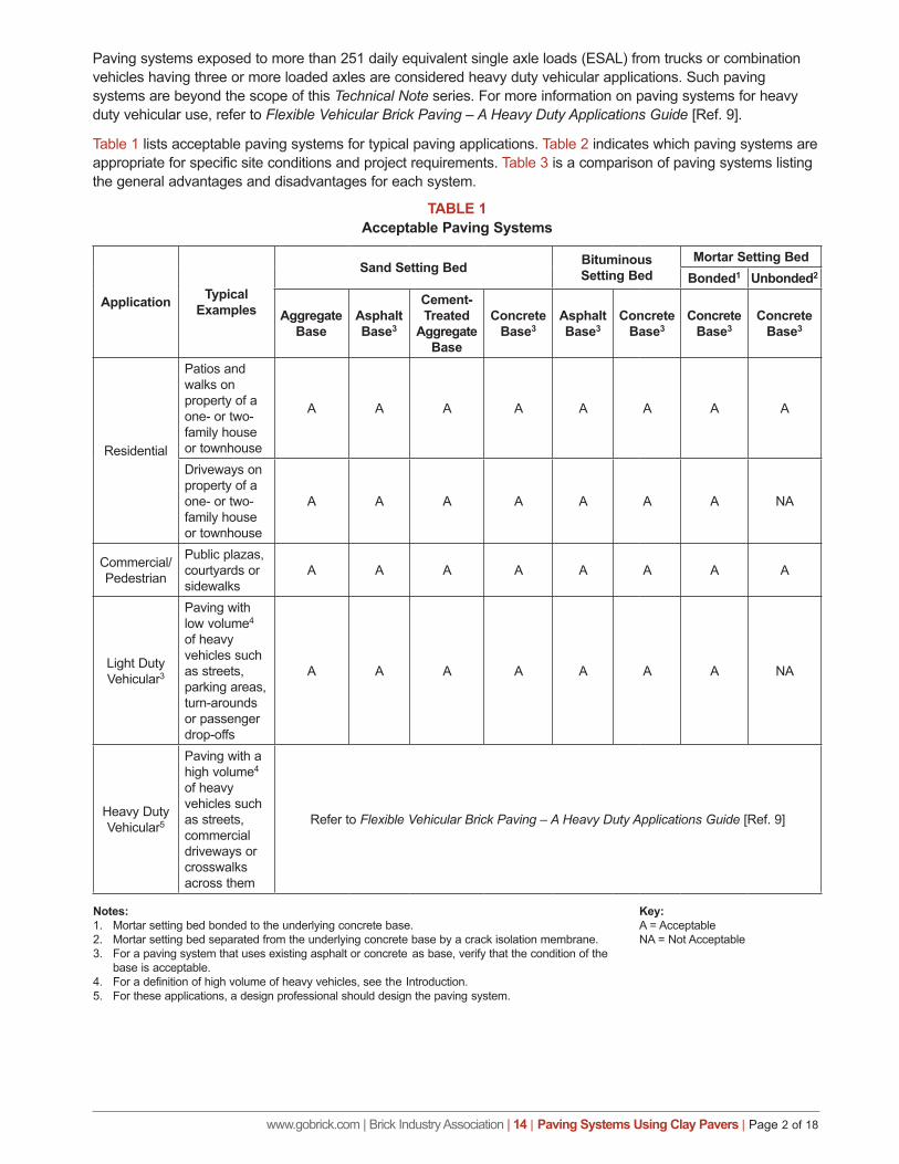
INTRODUCTIONTechnical Note 14 is the first in a series discussing the use of clay pavers for pedestrian and vehicular, residential and nonresidential applications (see Photo 1). It provides guidance in selecting a paving system (see Figure 1) and the appropriate clay paver, setting bed and base. Once these are determined, other Technical Notes in this series provide additional information specific to the setting bed chosen, including common construction for particular applications, typical details, installation practices and maintenance.
SUMMARY OF RECOMMENDATIONS:
Photo 1Pedestrian Plaza with Clay Pavers
Geotextile (If Required)
Compacted Subgrade
Compacted Base as Specified
Setting Bed as Specified
Wearing CourseFilled Joint as Specified
Typical Pavement Section
Clay Pavers
Specified Edge Restraint
Figure 1Typical Pavement Section
www.gobrick.com | Brick Industry Association | 14 | Paving Systems Using Clay Pavers | Page 2 of 18
Paving systems exposed to more than 251 daily equivalent single axle loads (ESAL) from trucks or combination vehicles having three or more loaded axles are considered heavy duty vehicular applications. Such paving systems are beyond the scope of this Technical Note series. For more information on paving systems for heavy duty vehicular use, refer to Flexible Vehicular Brick Paving – A Heavy Duty Applications Guide [Ref. 9].
Table 1 lists acceptable paving systems for typical paving applications. Table 2 indicates which paving systems are appropriate for specific site conditions and project requirements. Table 3 is a comparison of paving systems listing the general advantages and disadvantages for each system.
TABLE 1Acceptable Paving Systems
Application Typical Examples
Sand Setting Bed Bituminous Setting Bed
Mortar Setting BedBonded1 Unbonded2
Aggregate Base
Asphalt Base3
Cement-Treated
Aggregate Base
Concrete Base3
Asphalt Base3
Concrete Base3
Concrete Base3
Concrete Base3
Residential
Patios and walks on property of a one- or two- family house or townhouse
A A A A A A A A
Driveways on property of a one- or two- family house or townhouse
A A A A A A A NA
Commercial/Pedestrian
Public plazas, courtyards or sidewalks
A A A A A A A A
Light Duty Vehicular3
Paving with low volume4 of heavy vehicles such as streets, parking areas, turn-arounds or passenger drop-offs
A A A A A A A NA
Heavy Duty Vehicular5
Paving with a high volume4 of heavy vehicles such as streets, commercial driveways or crosswalks across them
Refer to Flexible Vehicular Brick Paving – A Heavy Duty Applications Guide [Ref. 9]
Notes:1. Mortar setting bed bonded to the underlying concrete base.2. Mortar setting bed separated from the underlying concrete base by a crack isolation membrane. 3. For a paving system that uses existing asphalt or concrete as base, verify that the condition of the
base is acceptable.4. For a definition of high volume of heavy vehicles, see the Introduction.5. For these applications, a design professional should design the paving system.
Key:A = AcceptableNA = Not Acceptable
www.gobrick.com | Brick Industry Association | 14 | Paving Systems Using Clay Pavers | Page 3 of 18
TABLE 2Selection of Setting Bed and Base
Site Condition or Project
Requirement
Sand Setting Bed Bituminous Setting Bed
Mortar Setting BedBonded1 Unbonded2
Aggregate Base
Asphalt Base
Cement-Treated
Aggregate Base
Concrete Base
Asphalt Base
Concrete Base
Concrete Base
Concrete Base
Soft Soil in Subgrade R R A A R A A A
Tree Roots in/near Subgrade R A NA NA A NA NA NA
Expansive Soil in Subgrade A3 R A NA R NA NA NA
Snow Melt System A4 A4 A4 R4 A3 NA R R
Suspended Structural Slab A3 NA A3 R3 NA R3 R R
Good Surface Drainage R R R R R R R R
Poor Surface Drainage R R R R R R NA NA
Permeable Pavement R NA NA NA NA NA NA NA
Deep Frost Line R3 R3 R3 R3 A3 A3 A A
Freeze/Thaw R3 R3 R3 R3 A3 A3 A NA
Minimal Frosts R R R R R R R R
Pressure Washing R3 R3 R3 R3 R3 R3 R R
Vacuuming R3 R3 R3 R3 R3 R3 R R
Minimal Cleaning R R R R R R R R
ADA Compliance R R R R R R A A
Pedestrians Only R R R R R R R R
Light Vehicular Traffic R5 R5 R5 R5 R5 R5 R NA
Notes:1. Mortar setting bed bonded to the underlying concrete base.2. Mortar setting bed separated from the underlying concrete base by a crack isolation membrane. 3. Use stabilized joint sand or apply a stabilizer to sand.4. When snow melt system is in sand setting bed, use stabilized sand in setting bed.5. Use Application PS or PX pavers
Key:R = RecommendedA = AcceptableNA = Not Acceptable
www.gobrick.com | Brick Industry Association | 14 | Paving Systems Using Clay Pavers | Page 4 of 18
TABLE 3Comparison of Pavements Made with Clay Pavers
Clay Pavers On: Advantages DisadvantagesSand Setting Bed on Aggregate Base
• Most durable• Cost-effective• Easy access to repair underground utilities• Good as overlay to existing asphalt or
concrete pavement• Allows use of semi-skilled labor• Can be designed as a permeable pavement
when open-graded aggregates are used
• Intensive cleaning may erode joint sand• May require a thicker base
Sand Setting Bed on Asphalt Base
• Good as overlay to existing asphalt pavement
• Intensive cleaning may erode joint sand
Sand Setting Bed on Cement-Treated Aggregate Base
• Good over poor soils or in small, confined areas
• Good as overlay to existing concrete pavement
• Intensive cleaning may erode joint sand
Sand Setting Bed on Concrete Base
• Good over poor soils or in small, confined areas
• Good as overlay to existing concrete pavement
• Intensive cleaning may erode joint sand• Requires good drainage above base• Susceptible to greater offset with subgrade
movement
Bituminous Setting Bed on Asphalt Base
• Reduced horizontal movement and uplift• Enhanced water penetration resistance
• Repairs are more difficult and expensive• Little tolerance for paver thickness variations
or inaccurate base elevations
Bituminous Setting Bed on Concrete Base
• Reduced horizontal movement and uplift• Enhanced water penetration resistance• Good over poor soils or in small, confined
areas
• Repairs are more difficult and expensive• Little tolerance for paver thickness variations
or inaccurate base elevations
Mortar Setting Bed Bonded to Concrete Base
• Greater tolerance for paver thickness variations or inaccurate base elevations
• Can be used on steeper slopes and with greater vehicle speeds
• Drainage occurs on the surface
• Movement joints must align through entire paving system
• Least cost-effective• Mortar joint maintenance required• Repairs are most difficult and expensive
Mortar Setting Bed Unbonded to Concrete Base
• Greater tolerance for paver thickness variations or inaccurate base elevations
• Movement joints in setting bed and base are not required to align
• Preferred when used over elevated structural slab
• Bond break must be used to avoid stresses caused by horizontal movement between layers
• Least cost-effective• Mortar joint maintenance required• Repairs are most difficult and expensive
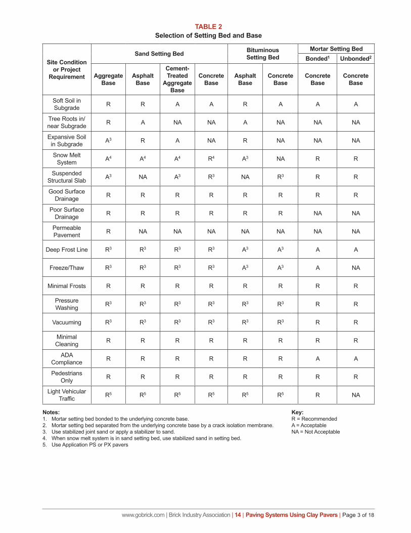
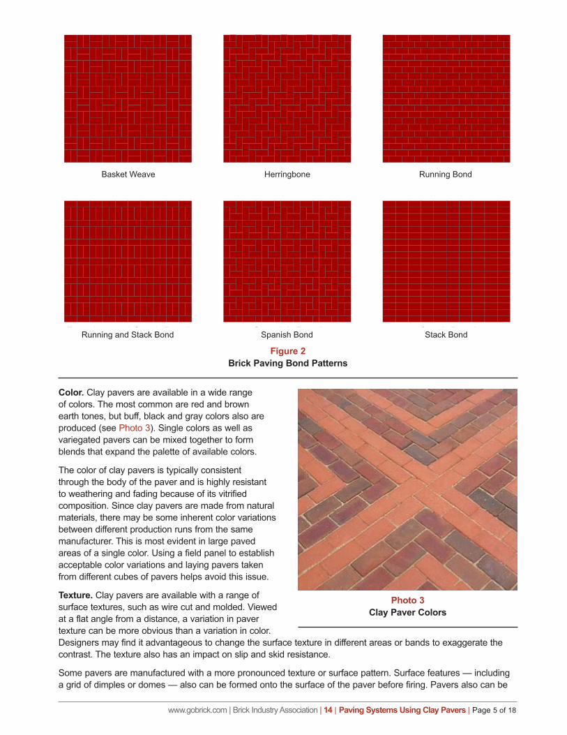
DESIGN CONSIDERATIONSAestheticsThe relatively small size of clay pavers creates a pavement surface with a human scale. As many pavers can be observed simultaneously, the nuances of different colors, textures and patterns can be clearly seen when standing on the pavement. Single colors can present a monolithic appearance. Using multiple colors can break down the scale of the pavement (see Photo 2). Borders laid in a different color can add interest to the pavement. In larger areas, it may be desirable to introduce different colors in the form of bands or panels. Some highly decorative pavements have introduced patterns that flow, repeat and intertwine (see Figure 2).
Photo 2Multiple Colors Affect Pavement Scale
www.gobrick.com | Brick Industry Association | 14 | Paving Systems Using Clay Pavers | Page 5 of 18
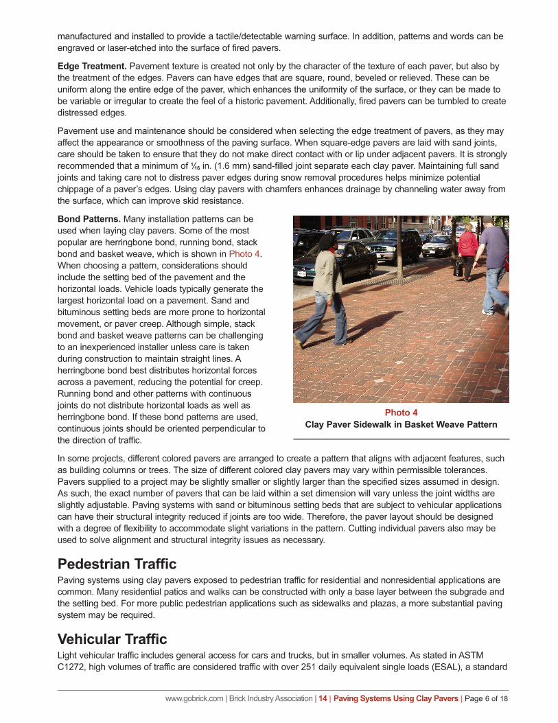
Color. Clay pavers are available in a wide range of colors. The most common are red and brown earth tones, but buff, black and gray colors also are produced (see Photo 3). Single colors as well as variegated pavers can be mixed together to form blends that expand the palette of available colors.
The color of clay pavers is typically consistent through the body of the paver and is highly resistant to weathering and fading because of its vitrified composition. Since clay pavers are made from natural materials, there may be some inherent color variations between different production runs from the same manufacturer. This is most evident in large paved areas of a single color. Using a field panel to establish acceptable color variations and laying pavers taken from different cubes of pavers helps avoid this issue.
Texture. Clay pavers are available with a range of surface textures, such as wire cut and molded. Viewed at a flat angle from a distance, a variation in paver texture can be more obvious than a variation in color. Designers may find it advantageous to change the surface texture in different areas or bands to exaggerate the contrast. The texture also has an impact on slip and skid resistance.
Some pavers are manufactured with a more pronounced texture or surface pattern. Surface features — including a grid of dimples or domes — also can be formed onto the surface of the paver before firing. Pavers also can be
Brick Paving Bond Patterns
Basket Weave Herringbone Running Bond
Running and Stack Bond Spanish Bond Stack Bond
Photo 3Clay Paver Colors
Basket Weave Herringbone Running Bond
Running and Stack Bond Spanish Bond
Figure 2Brick Paving Bond Patterns
Stack Bond
www.gobrick.com | Brick Industry Association | 14 | Paving Systems Using Clay Pavers | Page 6 of 18
manufactured and installed to provide a tactile/detectable warning surface. In addition, patterns and words can be engraved or laser-etched into the surface of fired pavers.
Edge Treatment. Pavement texture is created not only by the character of the texture of each paver, but also by the treatment of the edges. Pavers can have edges that are square, round, beveled or relieved. These can be uniform along the entire edge of the paver, which enhances the uniformity of the surface, or they can be made to be variable or irregular to create the feel of a historic pavement. Additionally, fired pavers can be tumbled to create distressed edges.
Pavement use and maintenance should be considered when selecting the edge treatment of pavers, as they may affect the appearance or smoothness of the paving surface. When square-edge pavers are laid with sand joints, care should be taken to ensure that they do not make direct contact with or lip under adjacent pavers. It is strongly recommended that a minimum of 1⁄16 in. (1.6 mm) sand-filled joint separate each clay paver. Maintaining full sand joints and taking care not to distress paver edges during snow removal procedures helps minimize potential chippage of a paver’s edges. Using clay pavers with chamfers enhances drainage by channeling water away from the surface, which can improve skid resistance.
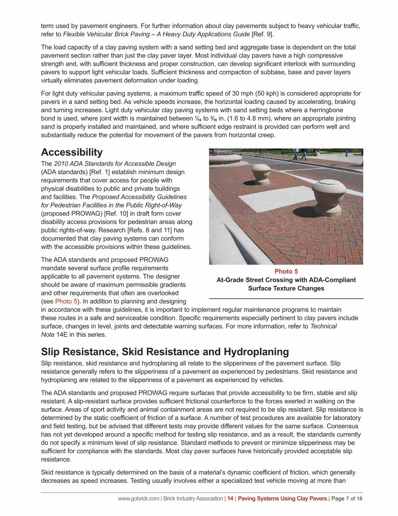
Bond Patterns. Many installation patterns can be used when laying clay pavers. Some of the most popular are herringbone bond, running bond, stack bond and basket weave, which is shown in Photo 4. When choosing a pattern, considerations should include the setting bed of the pavement and the horizontal loads. Vehicle loads typically generate the largest horizontal load on a pavement. Sand and bituminous setting beds are more prone to horizontal movement, or paver creep. Although simple, stack bond and basket weave patterns can be challenging to an inexperienced installer unless care is taken during construction to maintain straight lines. A herringbone bond best distributes horizontal forces across a pavement, reducing the potential for creep. Running bond and other patterns with continuous joints do not distribute horizontal loads as well as herringbone bond. If these bond patterns are used, continuous joints should be oriented perpendicular to the direction of traffic.
In some projects, different colored pavers are arranged to create a pattern that aligns with adjacent features, such as building columns or trees. The size of different colored clay pavers may vary within permissible tolerances. Pavers supplied to a project may be slightly smaller or slightly larger than the specified sizes assumed in design. As such, the exact number of pavers that can be laid within a set dimension will vary unless the joint widths are slightly adjustable. Paving systems with sand or bituminous setting beds that are subject to vehicular applications can have their structural integrity reduced if joints are too wide. Therefore, the paver layout should be designed with a degree of flexibility to accommodate slight variations in the pattern. Cutting individual pavers also may be used to solve alignment and structural integrity issues as necessary.
Pedestrian TrafficPaving systems using clay pavers exposed to pedestrian traffic for residential and nonresidential applications are common. Many residential patios and walks can be constructed with only a base layer between the subgrade and the setting bed. For more public pedestrian applications such as sidewalks and plazas, a more substantial paving system may be required.
Vehicular TrafficLight vehicular traffic includes general access for cars and trucks, but in smaller volumes. As stated in ASTM C1272, high volumes of traffic are considered traffic with over 251 daily equivalent single loads (ESAL), a standard
Photo 4Clay Paver Sidewalk in Basket Weave Pattern
www.gobrick.com | Brick Industry Association | 14 | Paving Systems Using Clay Pavers | Page 7 of 18
term used by pavement engineers. For further information about clay pavements subject to heavy vehicular traffic, refer to Flexible Vehicular Brick Paving – A Heavy Duty Applications Guide [Ref. 9].
The load capacity of a clay paving system with a sand setting bed and aggregate base is dependent on the total pavement section rather than just the clay paver layer. Most individual clay pavers have a high compressive strength and, with sufficient thickness and proper construction, can develop significant interlock with surrounding pavers to support light vehicular loads. Sufficient thickness and compaction of subbase, base and paver layers virtually eliminates pavement deformation under loading.
For light duty vehicular paving systems, a maximum traffic speed of 30 mph (50 kph) is considered appropriate for pavers in a sand setting bed. As vehicle speeds increase, the horizontal loading caused by accelerating, braking and turning increases. Light duty vehicular clay paving systems with sand setting beds where a herringbone bond is used, where joint width is maintained between 1⁄16 to 3⁄16 in. (1.6 to 4.8 mm), where an appropriate jointing sand is properly installed and maintained, and where sufficient edge restraint is provided can perform well and substantially reduce the potential for movement of the pavers from horizontal creep.
AccessibilityThe 2010 ADA Standards for Accessible Design (ADA standards) [Ref. 1] establish minimum design requirements that cover access for people with physical disabilities to public and private buildings and facilities. The Proposed Accessibility Guidelines for Pedestrian Facilities in the Public Right-of-Way (proposed PROWAG) [Ref. 10] in draft form cover disability access provisions for pedestrian areas along public rights-of-way. Research [Refs. 8 and 11] has documented that clay paving systems can conform with the accessible provisions within these guidelines.
The ADA standards and proposed PROWAG mandate several surface profile requirements applicable to all pavement systems. The designer should be aware of maximum permissible gradients and other requirements that often are overlooked (see Photo 5). In addition to planning and designing in accordance with these guidelines, it is important to implement regular maintenance programs to maintain these routes in a safe and serviceable condition. Specific requirements especially pertinent to clay pavers include surface, changes in level, joints and detectable warning surfaces. For more information, refer to Technical Note 14E in this series.
Slip Resistance, Skid Resistance and HydroplaningSlip resistance, skid resistance and hydroplaning all relate to the slipperiness of the pavement surface. Slip resistance generally refers to the slipperiness of a pavement as experienced by pedestrians. Skid resistance and hydroplaning are related to the slipperiness of a pavement as experienced by vehicles.
The ADA standards and proposed PROWAG require surfaces that provide accessibility to be firm, stable and slip resistant. A slip-resistant surface provides sufficient frictional counterforce to the forces exerted in walking on the surface. Areas of sport activity and animal containment areas are not required to be slip resistant. Slip resistance is determined by the static coefficient of friction of a surface. A number of test procedures are available for laboratory and field testing, but be advised that different tests may provide different values for the same surface. Consensus has not yet developed around a specific method for testing slip resistance, and as a result, the standards currently do not specify a minimum level of slip resistance. Standard methods to prevent or minimize slipperiness may be sufficient for compliance with the standards. Most clay paver surfaces have historically provided acceptable slip resistance.
Skid resistance is typically determined on the basis of a material’s dynamic coefficient of friction, which generally decreases as speed increases. Testing usually involves either a specialized test vehicle moving at more than
Photo 5At-Grade Street Crossing with ADA-Compliant
Surface Texture Changes
www.gobrick.com | Brick Industry Association | 14 | Paving Systems Using Clay Pavers | Page 8 of 18
30 mph (50 kph) or a portable British Pendulum Tester used in accordance with ASTM E303, Test Method for Measuring Surface Frictional Properties Using the British Pendulum Tester [Ref. 7]. For paving systems exposed to the light duty vehicular applications covered in this Technical Note 14 Series, skid resistance should not be an issue. Hydroplaning also is associated with speed, but in conjunction with standing water on the pavement surface. Due to the speed restrictions imposed on clay pavements subject to light duty vehicle traffic, hydroplaning should not be a concern for those clay pavements.
SlopePaving systems can be successfully used on slopes with up to a 10 percent grade. For projects where site conditions involve slopes exceeding 10 percent, a design professional and local codes should be consulted.
DrainageAdequate drainage is important to the performance and durability of any clay paving system. Water should be drained from the paving system as quickly as possible. A minimum slope of ¼ in. per ft of slope (2 percent grade) is recommended. Adequate drainage should be provided to ensure the integrity of all layers in a paving system.
Three types of drainage potentially exist in clay paving systems: surface restricted, subsurface restricted and unrestricted. Surface restricted drainage occurs on the surface of the paving system. This type of drainage is typical of clay paving systems with a mortar setting bed. Subsurface restricted drainage occurs when water drains over the surface and immediately below the paving course. This type of drainage is typical of paving systems installed with a bituminous setting bed. Unrestricted drainage involves draining water from the surface, the subsurface and through the subgrade. This type of drainage requires a sand setting bed on an aggregate base.
Drains should be selected and placed to adequately handle anticipated water flow. Drains serving paving systems should have openings not only on the surface but also on the sides. Such drains should be used for all paving systems to drain water from adjacent materials and to prevent capillary rise. Side openings should extend below the top of any impervious layer or membrane in the paving system. Drains placed in pavements with sand setting beds should have screens to prevent sand from entering the drain. Pavement edges that restrict water flow at the lowest point in the paving system where water is anticipated should have 2 in. (50 mm) weeps spaced at 16 in. (406 mm) on center filled with pea gravel.
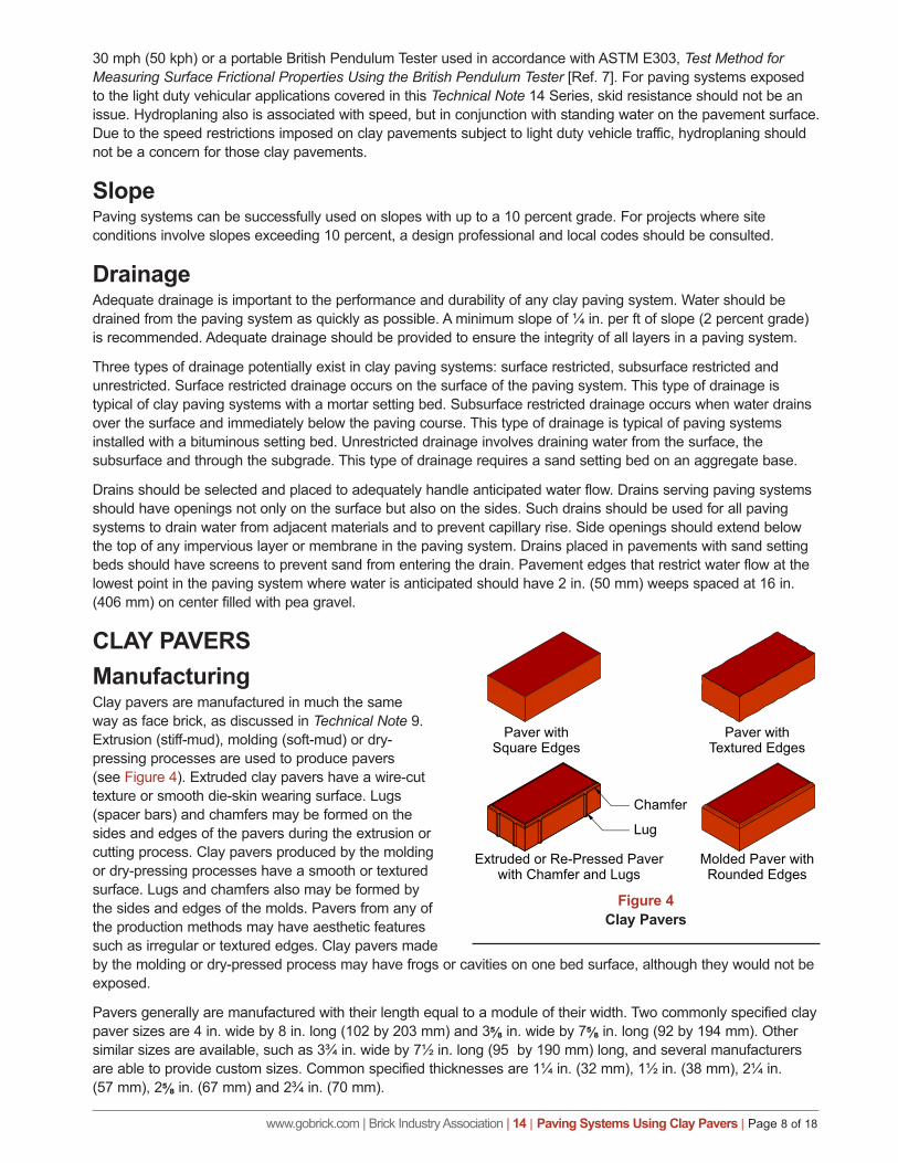
CLAY PAVERSManufacturingClay pavers are manufactured in much the same way as face brick, as discussed in Technical Note 9. Extrusion (stiff-mud), molding (soft-mud) or dry-pressing processes are used to produce pavers (see Figure 4). Extruded clay pavers have a wire-cut texture or smooth die-skin wearing surface. Lugs (spacer bars) and chamfers may be formed on the sides and edges of the pavers during the extrusion or cutting process. Clay pavers produced by the molding or dry-pressing processes have a smooth or textured surface. Lugs and chamfers also may be formed by the sides and edges of the molds. Pavers from any of the production methods may have aesthetic features such as irregular or textured edges. Clay pavers made by the molding or dry-pressed process may have frogs or cavities on one bed surface, although they would not be exposed.
Pavers generally are manufactured with their length equal to a module of their width. Two commonly specified clay paver sizes are 4 in. wide by 8 in. long (102 by 203 mm) and 3⅝ in. wide by 7⅝ in. long (92 by 194 mm). Other similar sizes are available, such as 3¾ in. wide by 7½ in. long (95 by 190 mm) long, and several manufacturers are able to provide custom sizes. Common specified thicknesses are 1¼ in. (32 mm), 1½ in. (38 mm), 2¼ in. (57 mm), 2⅝ in. (67 mm) and 2¾ in. (70 mm).
Clay Pavers
Paver withSquare Edges
Paver withTextured Edges
Extruded or Re-Pressed Paverwith Chamfer and Lugs
Chamfer
Lug
Molded Paver withRounded Edges
Figure 4Clay Pavers
www.gobrick.com | Brick Industry Association | 14 | Paving Systems Using Clay Pavers | Page 9 of 18
StandardsClay pavers can be used as a wearing course in many exterior pavement and interior floors. Most pavers in the United States are manufactured to comply with consensus standards published by ASTM International (ASTM). Two ASTM standards define requirements for clay pavers for exterior use: ASTM C902, Standard Specification for Pedestrian and Light Traffic Paving Brick [Ref. 2], and ASTM C1272, Standard Specification for Heavy Vehicular Paving Brick [Ref. 3]. For light duty applications addressed by the Technical Note 14 Series, clay pavers complying with ASTM C902 are normally used. Clay pavers manufactured to meet ASTM C1272 may be used in light duty or heavy vehicular applications and may provide longer pavement service life — especially where the pavement is subject to higher volumes of vehicular traffic. Only clay pavers meeting the requirements of ASTM C1272 are suitable for heavy vehicular applications, which are covered in Flexible Vehicular Brick Paving – A Heavy Duty Applications Guide.
ASTM C902. This specification covers clay pavers suitable for patios, walkways, floors, plazas, residential driveways and commercial driveways (passenger drop-offs). It describes three Classes and three Types of clay pavers according to severity of their exposure to weather and to traffic, respectively. Three Applications also are defined, based upon the pavers’ intended use, and limit their dimensional tolerances, distortion and extent of chipping.
Class – A paver’s Class relates to its resistance to damage from exposure to weather and is based on compressive strength and absorption properties. Class SX pavers are intended for use where the pavers may be frozen while saturated with water. Class MX pavers are intended for exterior use where the pavers will not be exposed to freezing conditions. Class NX pavers are not acceptable for exterior use but may be used for interior areas where the pavers are protected from freezing when wet. For most exterior residential or light duty applications, Class SX pavers are used.
Type – A paver’s Type relates to its resistance to abrasion. Type I pavers are intended for use where the pavers are exposed to extensive abrasion, such as sidewalks and driveways in publicly occupied spaces. Type II pavers are intended for use where the pavers are exposed to intermediate pedestrian traffic, such as heavily traveled residential walkways and residential driveways. Type III pavers are intended for use in low pedestrian traffic, residential areas such as floors and patios of single-family homes. For most exterior residential or light duty applications, Type I or II pavers are used.
Application – A paver’s Application relates to its aesthetics and use. Application PS pavers are intended for general use and can be installed in any bond pattern with either mortar or sand-filled joints when not exposed to vehicular traffic. When Application PS pavers are installed with sand-filled joints for light duty vehicular applications, they should be laid in running bond or other bonds not requiring extremely close dimensional tolerances. Any bond pattern can be used when Application PS pavers are installed with mortar joints. Application PX pavers have tighter dimensional tolerances that allow consistently narrow joints between pavers. Such uses include pavements without mortar joints between pavers where exceptionally close dimensional tolerances are required as a result of special bond patterns or unusual construction requirements. Application PA pavers are characterized by aesthetic effects such as variability in size, color and texture. Such pavers have performed successfully in many historic clay paving applications and are generally used where a distinctive architectural character is desired. Such applications are often installed with mortar joints between pavers, but they can be successful in sand-filled joint applications that are laid by workers with experience installing Application PA pavers in this manner. Using stabilized joint sand or applying stabilizer to joint sand will help prevent sand loss from wider sand-filled joints.
Pavers complying with ASTM C902 are not required to have a minimum thickness. However, they are commonly manufactured to a specified thickness of 2¼ in. (57 mm) and 1½ in. (38 mm). Except for patios or walks for one- or two-family homes in warm climates with limited frost exposure, clay pavers 1½ in. (38 mm) thick are usually installed only over a rigid base.
ASTM C1272. This standard addresses heavy vehicular pavers generally used in streets, commercial driveways and industrial applications. ASTM C1272 designates two Types of pavers depending on their method of installation. Three Applications limit dimensional tolerances, distortion and extent of chipping.
The paver Type is based upon the compressive strength, breaking load and absorption properties of the pavers. Type F pavers are intended to be set in a sand setting bed with sand-filled joints. Type F pavers are required to be no less than 2⅝ in. (67 mm) thick exclusive of chamfers. They also can be installed over flexible or rigid bases.
www.gobrick.com | Brick Industry Association | 14 | Paving Systems Using Clay Pavers | Page 10 of 18
Type R pavers are intended to be set in a mortar setting bed with mortar joints over a concrete base. Type R pavers also can be set on a bituminous setting bed with sand-filled joints and supported by an asphalt or concrete base. The minimum thickness for Type R pavers is required to be 2¼ in. (57 mm).
Applications PS, PX and PA are common to both ASTM standards and denote similar requirements. Pavers complying with ASTM C1272 may contain frogs but must be without cores or perforations.
ASTM Properties for Clay Pavers. The Class, Type and Application designations within ASTM clay paver standards are based upon physical properties and characteristics, including compressive strength, breaking load, absorption, abrasion, dimensional tolerances and extent of chipping. Pavers must be resistant to damage from the effects of traffic and the environment. In many regions of the United States, clay pavers will be exposed to severe environmental conditions. Pavers often are in a saturated condition and can experience numerous freeze/thaw cycles. Application of deicing chemicals can cause additional thermal shock to pavers. Compliance with property requirements of ASTM C902 and C1272 provides the required durability.
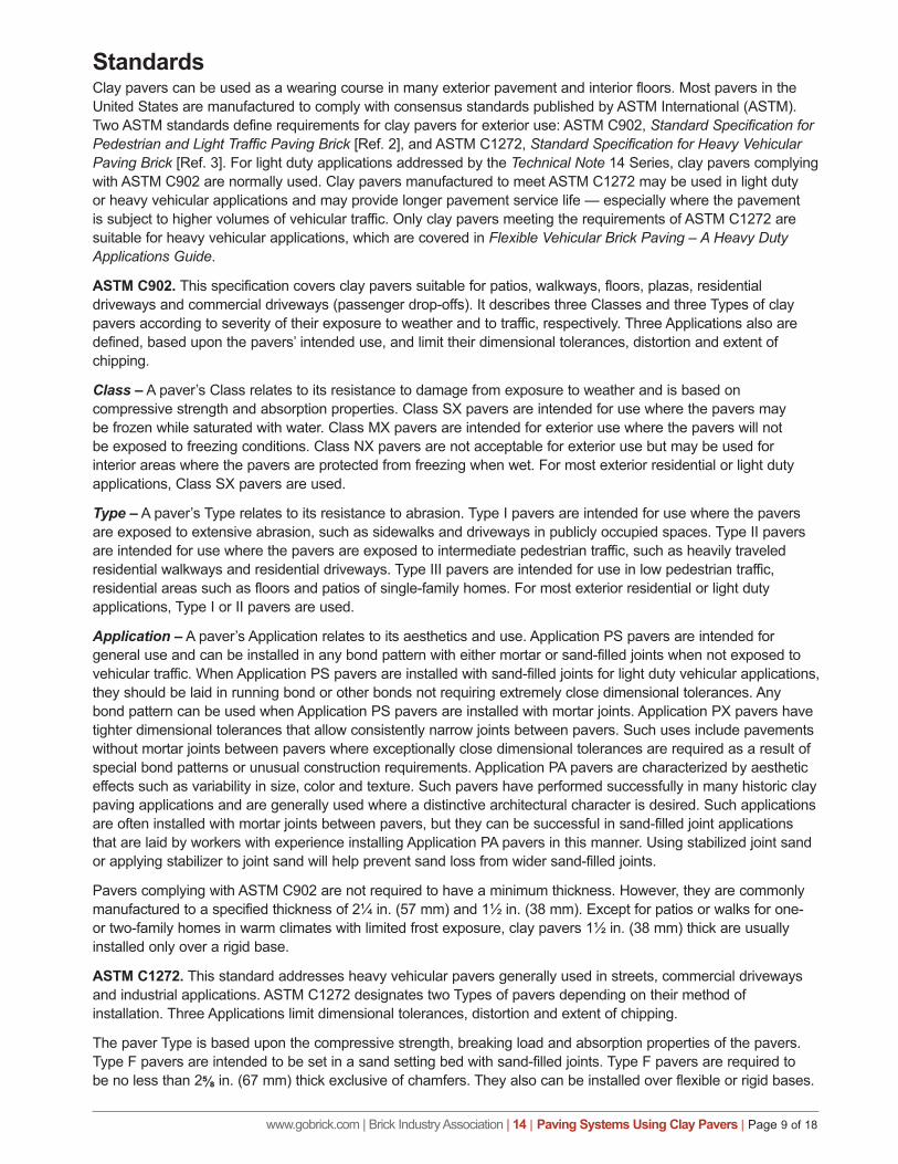
Compressive Strength, Breaking Load and Absorption – The strength and absorption requirements of pavers from the ASTM standards are shown in Table 4. Some pavers are durable but cannot be classified under the physical requirements shown in Table 4. Using alternatives in the specifications allows pavers that are known to perform well to meet the durability requirement. It does not signify that the pavers are of a lower quality.
TABLE 4Property Requirements
ASTM Standard
Min. Compressive Strength, psi (Mpa)
Max. Cold Water Absorption, %
Max. Saturation Coefficient
Min. Breaking Load, lb/in. (kN/mm)
Avg of 5 Brick Individual Avg of
5 Brick Individual Avg of 5 Brick Individual Avg of
5 Brick Individual
C902 Class SX 8000 (55.2)
7000 (48.3) 8.0 11.0 0.78 0.80 — —
Class SX (molded)
4000 (27.6)
3500 (24.1) 16.0 18.0 0.78 0.80 — —
Class MX 3000 (20.7)
2500 (17.2) 14.0 17.0 No limit No limit — —
Class NX 3000 (20.7)
2500 (17.2) No limit No limit No limit No limit — —
C1272 Type R 8000 (55.2)
7000 (48.3) 6.0 7.0 — — — —
Type F 10,000 (69.0)
8800 (60.7) 6.0 7.0 — — 475 (83) 333 (58)
For pavers complying with ASTM C902 or C1272, several alternatives are allowed. The freezing and thawing test alternative allows the cold water absorption and the saturation coefficient to be waived if a sample of five brick that meet all other requirements passes the freezing and thawing test of ASTM C67 without breaking and with no greater than 0.5 percent loss in dry weight of any individual unit. The sulfate soundness alternative allows the cold water absorption and saturation coefficient to be waived if five brick survive 15 cycles of the sulfate soundness test with no visible damage. The performance alternative allows specifiers to waive all property requirements for pavers if they are satisfied with information furnished by the manufacturer on the performance of the pavers in a similar application subject to similar exposure and traffic.
For pavers complying with ASTM C902, the absorption alternative allows the saturation coefficient to be waived for pavers that absorb less than 6.0 percent after 24 hours of submersion in room-temperature water.
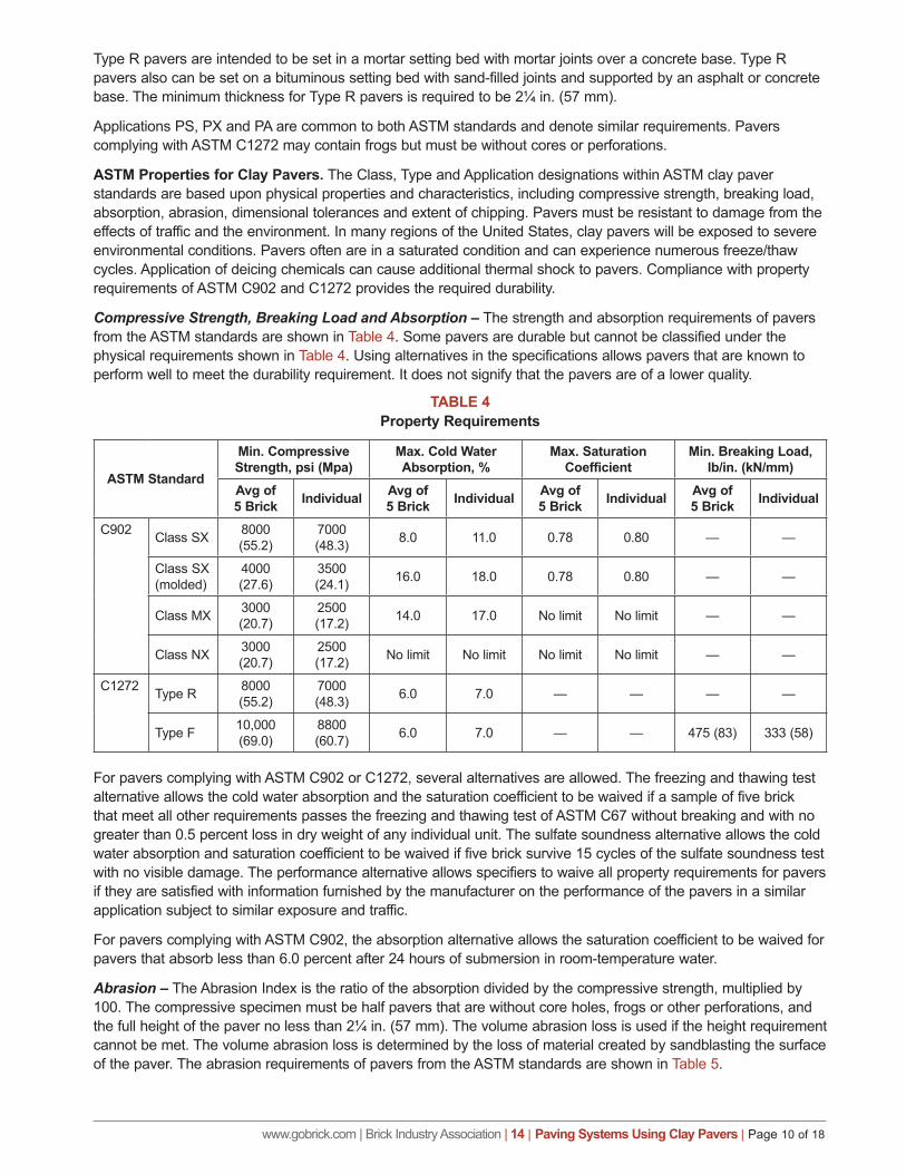
Abrasion – The Abrasion Index is the ratio of the absorption divided by the compressive strength, multiplied by 100. The compressive specimen must be half pavers that are without core holes, frogs or other perforations, and the full height of the paver no less than 2¼ in. (57 mm). The volume abrasion loss is used if the height requirement cannot be met. The volume abrasion loss is determined by the loss of material created by sandblasting the surface of the paver. The abrasion requirements of pavers from the ASTM standards are shown in Table 5.
www.gobrick.com | Brick Industry Association | 14 | Paving Systems Using Clay Pavers | Page 11 of 18
TABLE 5Maximum Abrasion Requirements
ASTM Standard Abrasion Index Volume Abrasion Loss (cm3/cm2)
C902 Type I 0.11 1.7Type II 0.25 2.7Type III 0.50 4.0
C1272 Type R & F 0.11 1.7
Dimensional Tolerances – The dimensional tolerances for pavers are based upon the dimension — width, height or length — considered. The actual dimensions may vary from the specified dimension by no more than plus or minus the dimensional tolerance. The tolerances for both C902 and C1272 pavers are shown in Table 6.
TABLE 6Dimensional Tolerance Requirements
Dimension, in. (mm)ASTM C902 and C1272
Application PS, in. (mm) Application PX, in. (mm) Application PA3 (76) and under ⅛ (3.2) 1⁄16 (1.6) No limit
over 3 to 5 (76 to 127) 3⁄16 (4.7) 3⁄32 (2.4) No limit
over 5 to 8 (127 to 203) ¼ (6.4) ⅛ (3.2) No limit
over 8 (203) 5⁄16 (7.9) 7⁄32 (5.6) No limit
Chippage – Clay pavers may chip in transit or during construction. Table 7 shows the extent of chippage allowed by prescribing the maximum distance that chips may extend into the surface of a paver from an edge or a corner. The sum of the length of chips on a single paver must not exceed 10 percent of the perimeter of the exposed face of the paver. Cobbled or tumbled pavers that are intentionally distressed after production are classified as Application PA pavers.
TABLE 7Maximum Chippage Requirements
ASTM Standard Edge, in. (mm) Corner, in. (mm)C902 Application PS 5⁄16 (7.9) ½ (12.7)
Application PX ¼ (6.4) ⅜ (9.5)
Application PA As specified by purchaser As specified by purchaser
C1272 Application PS & PX 5⁄16 (7.9) ½ (12.7)
Application PA No limit No limit
Warpage – Both ASTM C902 and C1272 limit distortion and warpage of surfaces and edges intended to be exposed in use. The warpage must not exceed the maximum for the Application specified as noted in Table 8.
TABLE 8Tolerances on Warpage
Specified Dimension, in. (mm)
ASTM C902 & C12721
Maximum Permissible Distortion, in. (mm)Application PS Application PX Application PA
8 (203) and under 3⁄32 (2.4) 1⁄16 (1.6) No limit
Over 8 (203) to 12 (305) ⅛ (3.2) 3⁄32 (2.4) No limit
Over 12 (305) to 16 (406) 5⁄32 (4.0) ⅛ (3.2) No limit
1. ASTM C1272 Type F clay paver required to meet Application PX
www.gobrick.com | Brick Industry Association | 14 | Paving Systems Using Clay Pavers | Page 12 of 18
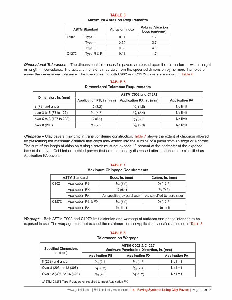
SETTING BEDSSetting beds provide a means to adjust for dimensional variations in the height of a paver. They also support the clay pavers and transfer load to the base.
Sand Setting BedIndividual pavers in sand setting beds are held in position by the frictional interlock that is developed in each sand-filled joint between adjacent pavers. The joints transfer vertical and horizontal forces, but can also absorb expansion and contraction of the individual pavers. If the pavement deflects slightly, the pavers will realign themselves to the new profile without significant loss in structural capacity. Interlock is developed by properly sized joints filled with consolidated joint sand. Sand setting beds may be installed directly on an aggregate base, asphalt base, cement-treated aggregate base or concrete base. For further information about pavements with sand setting beds, refer to Technical Note 14A.
Bituminous Setting BedIn pavements with a bituminous setting bed, less interlock is developed by the joint material than in pavements with a sand setting bed. However, additional restraint is provided by the adhesive nature of the tack coat. Bituminous setting beds can be set on an asphalt base or concrete base. For further information about pavements with bituminous setting beds, refer to Technical Note 14B.
Mortar Setting BedPavers in a mortar setting bed are bonded to the underlying mortar bed and transfer most of the vertical load through direct bearing. Mortar setting beds should be used only with a concrete base and may be bonded or unbonded to it. The joints between pavers are filled with mortar that transfers horizontal load. However, mortar will not absorb expansion and contraction of individual pavers. If the pavement deflects significantly, it may crack along mortar lines or across pavers. For further information about pavements with mortar setting beds, refer to Technical Note 14C.
BASESThe base layer in the pavement is the primary structural layer. It is subjected to the compressive, tensile and shearing stresses transmitted through the wearing course. Materials in the base layer need to be capable of resisting these stresses. Pedestrian loading is sufficiently light that a base thickness of only 4 in. (102 mm) is required when no specific site conditions dictate a thicker base. Vehicular loading requires a thicker base.
Including a subbase often provides economic benefits when the subgrade is of low strength or is susceptible to frost. Because it is lower in the pavement section, the subbase is subjected to lower stresses than the base course (see Figure 1). A subbase also can serve as a working platform to prevent subgrade damage from construction equipment. Subbase material also may be added to increase the depth of the pavement section in frost-susceptible soils.
Aggregate Subbase and BaseAggregate subbase materials are typically medium-quality graded aggregates or clean sand-and-gravel mixtures. They should not be susceptible to deterioration from moisture or freezing. Subbase materials are covered by ASTM D2940, Specification for Graded Aggregate Material for Bases or Subbases for Highways or Airports [Ref. 6]. Typical gradation envelopes are prescribed, along with other properties such as durability and plasticity. Aggregate subbase materials generally are graded from 1½ in. (38 mm) to No. 200 (0.075 mm) sizes. Aggregate subbase materials may be used directly over the subgrade soil or on top of a geotextile.
Aggregate base materials are typically high-quality, crushed, dense-graded aggregates. They usually are specified in ASTM D2940. Aggregate base materials generally are graded from ¾ in. (19.1 mm) to No. 200 (0.075 mm) sizes. An aggregate base may be placed directly on the subgrade or over an aggregate subbase. A sand setting bed may be installed directly on an aggregate base.
It is important to compact aggregate subbase and base layers. See compaction recommendations under “Paver Layer Construction.”
www.gobrick.com | Brick Industry Association | 14 | Paving Systems Using Clay Pavers | Page 13 of 18
Asphalt BaseAsphalt base materials consist of mixtures of aggregates and asphalt cement mixed into an asphalt cement that is produced at a central hot-mix plant. Asphalt concrete should conform to industry standards or local Department of Transportation requirements. Asphalt aggregates usually are blended to achieve a gradation from ½ in. (12.7 mm) or ⅜ in. (9.5 mm) to No. 200 (0.075 mm). An asphalt base may be placed directly on the subgrade but is more commonly laid over an aggregate subbase or base. It creates a relatively stiff and impermeable base layer.
Cement-Treated Aggregate BaseA cement-treated aggregate base material is a relatively dry, lean mixture of aggregate and portland cement that creates a stiff and impermeable base layer. These materials should be mixed at a concrete plant and laid by machine. Cement contents vary between 5 and 12 percent with sufficient water added to achieve required compaction and full hydration of cement. Compressive strengths typically are around 750 psi (5.17 MPa). A cement-treated aggregate base may be placed directly on the subgrade but is more commonly laid over an aggregate subbase. This type of base does not include reinforcement and, because of the low water and cement content, can be laid without movement joints.
Concrete BaseThe compressive strength of a concrete base should be at least 4000 psi (27.6 MPa). Concrete bases should be reinforced with welded wire fabric or reinforcement bars, incorporating a grid of movement joints with load transfer devices, such as dowels or keyways, to limit vertical separation across the joint. Layouts of movement joints require careful consideration of the overlying pavement system. Movement joints placed more than 12 ft (3.66 m) apart should extend through the entire pavement to prevent damage to the pavers unless using an unbonded system. A concrete base should be placed over an aggregate subbase or base.
SUBGRADEThe subgrade is classified by the existing soil conditions, the environment and drainage. For vehicular applications, the existing soil conditions for the project should be determined by a geotechnical engineer before design of the paving system. For pedestrian and residential applications, a geotechnical engineer should be used as necessary to verify suitability of existing soil for the proposed paving system.
Environmental conditions and the quality of drainage can affect the support provided by the subgrade. In wet climates, poorly drained areas or those that experience freezing conditions, the support from the subgrade is likely to be reduced during certain periods of the paving system’s life. Conversely, in arid climates or well-drained areas, it is likely that a higher degree of subgrade support will be experienced during part of the paving system’s life. Where water can penetrate the subgrade, it is important to drain it quickly to alleviate any potential fluctuations in soil moisture content.
Soils are typically classified into different groups to represent their engineering properties. In general, soils consisting primarily of gravel and sand can be used to support most paving systems. In general, soil consisting of clay usually can be used to support a paving system, as long as it is located in a dry environment or is drained. Soils classified as organic are not suitable for subgrade and should be removed and replaced. For further guidance regarding soil capacities, refer to Flexible Vehicular Brick Paving – A Heavy Duty Applications Guide [Ref. 9].
It is important that the subgrade be adequately compacted. See compaction recommendations under “Paver Layer Construction.”
GEOTEXTILEGeotextiles are formed from plastic yarns or filaments such as polypropylene and polyester. They may be woven or nonwoven fabrics supplied in rolls. A geotextile may be used between fine-grained subgrade materials and base or subbase layers, particularly where moist conditions are anticipated. This separates the two layers, preventing the intrusion of fine soil particles into the overlying granular layer and preventing larger aggregates from punching down into the subgrade. This enables the base to retain its strength over a longer period. Geotextiles also can provide limited reinforcement to the overlying pavement layer. As the subgrade begins to deform, the geotextile is
www.gobrick.com | Brick Industry Association | 14 | Paving Systems Using Clay Pavers | Page 14 of 18
put into tension, which reduces the loading on the subgrade, slowing rut development. To select the appropriate geotextile for particular soil conditions, consult the geotextile manufacturer’s recommendations.
PAVEMENT LAYER CONSTRUCTIONSubgrade PreparationThe subgrade should be excavated to achieve a uniform pavement thickness, and any substandard or soft materials should be undercut and replaced with acceptable backfill. A subsurface drainage system may be installed as perforated pipes or fin drains if necessary. All utility trenches should be properly backfilled and each layer thoroughly compacted to prevent settlement. The subgrade should be scarified and moisture conditioned to within 2 percent of optimum moisture content as determined by ASTM D698, Test Methods for Laboratory Compaction Characteristics of Soil Using Standard Effort (12,400 ft-lbf/ft3 (600 kN-m/m3)) [Ref. 4], to a depth of 6 in. (152 mm). Moisture conditioning clay subgrades can be more complicated, because the clay absorbs water more slowly. It should then be graded to the appropriate profile and compacted by rolling with appropriate static or vibratory rollers.
Compaction of the subgrade should be at least 98 percent of standard Proctor density for clay and 100 percent maximum dry density for sand/gravel, as specified by ASTM D698. However, modified Proctor density as specified in ASTM D1557, Standard Test Methods for Laboratory Compaction Characteristics of Soil Using Modified Effort (56,000 ft-lbf/ft3 (2,700 kN-m/m3)) [Ref. 5], is preferred, especially for areas under constant vehicular traffic.
GeotextileWhen a geotextile is used, it should be placed immediately before spreading the aggregate subbase or aggregate base. Geotextiles are not used when other base types are constructed directly on the subgrade. Care should be taken to stretch the material as it is unrolled to remove any wrinkles. A minimum lap of 12 in. (305 mm) should be provided at the sides and ends of rolls. Construction equipment should not be allowed to operate directly on the geotextile.
Aggregate Subbase and BaseAggregate subbase and base courses are spread in layers of up to 6 in. (152 mm) in compacted thickness, dependent upon the proposed compaction process. Material may be end-dumped from the delivery trucks and spread by grader spreaders or by hand with care to avoid segregation. The material should be moisture conditioned to within 2 percent of the optimum moisture content from ASTM D698. It should then be compacted by rolling with appropriate static or vibratory rollers, or with a plate vibrator. When using a plate vibrator, the layer thickness must be 3 in. (76 mm) or less, and more than one layer may be required. Subbase and base layers for pedestrian areas and residential driveways should be compacted to a minimum of 98 percent standard Proctor density as determined by ASTM D698. For vehicular areas, compaction of the subbase and base layers should be at least 98 percent modified Proctor as determined by ASTM D1557. Limited regrading is permissible to achieve correct surface profile and elevations. The maximum variation under the setting bed should be ±3⁄16 in. (4.8 mm) when tested with a 10 ft (3.05 m) straightedge laid on the surface. The minimum slope of the aggregate base should be 1 in. (25.4 mm) in 4 ft (1.22 m) to allow for drainage.
Asphalt BaseAsphalt materials are produced at a hot-mix plant. They are mixed at temperatures up to 300 °F (149 °C) and should be installed before they cool to temperatures below 200 °F (93 °C). Asphalt base layers can be spread by machine or by hand. Asphalt can be laid in lifts from 1½ to 3 in. (38 to 76 mm) in thickness depending on the aggregate size and compaction equipment. Hand spreading requires adequate compaction of the base. Machine installation using a paving machine provides initial compaction, enabling more accurate placement and elevations to be achieved. Compaction of the asphalt is accomplished by an initial “breakdown” rolling and then by a finish rolling with steel- or rubber-tired rollers. Compaction is continued until the required density is achieved. This normally is a minimum of 96 percent of the density of samples of the same material compacted in a laboratory. Once materials have cooled to the ambient temperature, the layer can receive traffic, although the asphalt continues to stiffen over several months. The maximum variation under the setting bed should be ±3⁄16 in. (4.8 mm) when a 10 ft (3.05 m) straightedge is laid on the surface. The minimum slope of the asphalt base surface should be 1 in. (25.4 mm) in 4 ft (1.22 m) to allow for drainage.
www.gobrick.com | Brick Industry Association | 14 | Paving Systems Using Clay Pavers | Page 15 of 18
Cement-Treated Aggregate BasePlant-mixed cement-treated aggregate bases are transported to the site for spreading by machine or by hand. When spread by a paving machine, the base should be compacted to the appropriate thickness. When spread by a grader or by hand, adequate compaction is required. A cement-treated aggregate base also can be mixed in place using special equipment. A granular subgrade or imported aggregate is thoroughly mixed with cement and water to achieve the required thickness. Materials should be placed and compacted within two hours of adding water and before initial set of the cement. The base should be compacted according to ASTM D1557 to at least 98 percent of the maximum dry density. The cement-treated layer should be cured by water misting or by applying an asphalt emulsion cure coat. Traffic should not be allowed on the base for at least seven days, but paver installation may commence after three days. The maximum variation under the setting bed should be ±3⁄16 in. (4.7 mm) when a 10 ft (3.05 m) straightedge is laid on the surface. The minimum slope of the base surface should be 1 in. (25.4 mm) in 4 ft (1.22 m) to allow for drainage.
Concrete BaseConcrete usually is plant-mixed and delivered to the site in ready-mix trucks. It is discharged between forms, where it is spread and consolidated. The formwork is set to the correct elevations, and a vibrating screed is drawn between the forms to achieve the appropriate surface elevations. Movement joints containing load-transfer devices may be formed at the edges of each pour, or the devices can be cast into the concrete between forms. Saw cutting may be undertaken to induce cracking at the desired locations. A concrete base may be finished with a broom, brush or wood float. A polished surface finish should be avoided. Care should be taken to follow proper curing procedures for at least 14 days. Vehicular loads should not be permitted for at least seven days, but paver installation may commence after three days. The maximum variation under the setting bed should be ±3⁄16 in. (4.7 mm) when a 10 ft (3.05 m) straightedge is laid on the surface. The minimum slope of the concrete base surface should be 1 in. (25.4 mm) in 4 ft (1.22 m) to allow for drainage.
CLEANING AND MAINTENANCEClay pavers are highly resistant to absorption of stains and can be kept clean in most environments by regular sweeping. Otherwise, cleaning of brick pavements is essentially the same as cleaning vertical brickwork, as discussed in Technical Note 20. Mortar-filled joints generally are more resistant to aggressive cleaning methods (i.e., pressure washers). Sand-filled joints that will be subjected to aggressive cleaning methods should be constructed with stabilized joint sand or should be treated with a joint sand stabilizer. Cleaning solutions, polymeric sands or other products applied directly to clay pavers should always be tested on a small area before application to the entire project. Some of these products have been known to haze, stain or discolor certain pavers.
EfflorescenceEfflorescence is a white, powdery substance that may occasionally appear on the surface of pavers. It is the product of soluble compounds normally found in other pavement components or underlying soils, which are deposited on the surface of the paver as absorbed water evaporates from the pavement surface. Soluble compounds absorbed by the pavement from deicing chemicals also may cause efflorescence. Efflorescence often can be vacuumed or brushed off the surface and removed from dry pavers. Washing downhill with water may temporarily dissipate soluble compounds by dissolving them. However, care must be taken to ensure that the contaminated water drains away from and does not re-enter the paving system.
In many cases, efflorescence will be minimal and will wear away naturally with traffic and weathering during the early life of the pavement. If the salts are the result of groundwater or other more persistent water ingress, proprietary cleaners are available to assist in their removal. Proper surface and subsurface drainage are critical in these situations. For further information on efflorescence, refer to Technical Notes 23 and 23A.
Ice RemovalSeveral proprietary chemical products are available for preventing and removing ice from paved surfaces; these perform well and reduce potential staining of pavers. Among these are calcium magnesium acetate and urea. The former is preferred because it is more effective at lower temperatures. Rock salt is not recommended since it contains calcium chloride that can cause efflorescence. Sand or grit used to provide traction on ice should be swept up after the freezing cycle to minimize grinding of the pavers.
www.gobrick.com | Brick Industry Association | 14 | Paving Systems Using Clay Pavers | Page 16 of 18
Snow RemovalClearing snow from clay pavements can be undertaken using plows, snow blowers, shovels and brushes, as used for other pavements. Care must be taken to ensure that the blades of the equipment do not scrape the pavement surface in a manner that might cause chipping. Rubber or urethane blade edges can be used, or proper blade height can be maintained above the pavement surface using guide wheels. Any residual snow can be cleared with brushes. Some snow-clearing procedures use heavy equipment to stockpile and subsequently remove the snow from the property. If such equipment is used, then the load capacity of the pavement should be adequately designed.
SPECIAL APPLICATIONS AND CONDITIONSClay pavers can be used in a number of special applications that require consideration of additional aspects. The following sections cover the design of clay paver wearing surfaces for suspended decks, permeable paving systems and hydronic snowmelt systems.
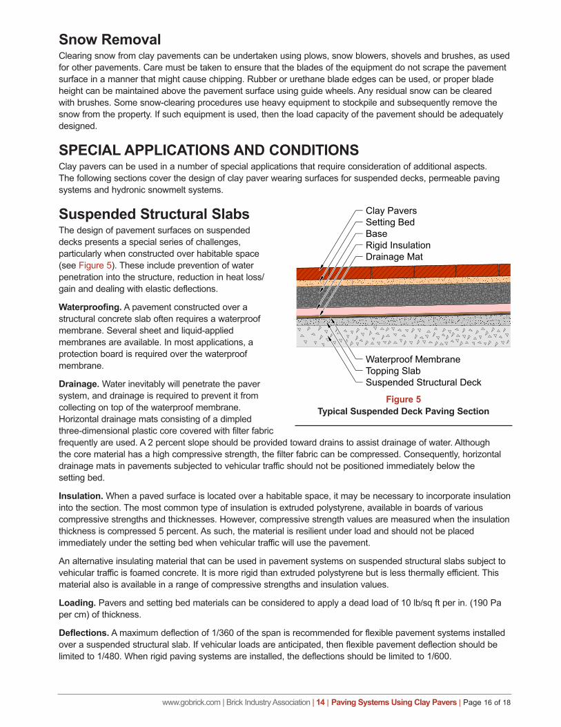
Suspended Structural SlabsThe design of pavement surfaces on suspended decks presents a special series of challenges, particularly when constructed over habitable space (see Figure 5). These include prevention of water penetration into the structure, reduction in heat loss/gain and dealing with elastic deflections.
Waterproofing. A pavement constructed over a structural concrete slab often requires a waterproof membrane. Several sheet and liquid-applied membranes are available. In most applications, a protection board is required over the waterproof membrane.
Drainage. Water inevitably will penetrate the paver system, and drainage is required to prevent it from collecting on top of the waterproof membrane. Horizontal drainage mats consisting of a dimpled three-dimensional plastic core covered with filter fabric frequently are used. A 2 percent slope should be provided toward drains to assist drainage of water. Although the core material has a high compressive strength, the filter fabric can be compressed. Consequently, horizontal drainage mats in pavements subjected to vehicular traffic should not be positioned immediately below the setting bed.
Insulation. When a paved surface is located over a habitable space, it may be necessary to incorporate insulation into the section. The most common type of insulation is extruded polystyrene, available in boards of various compressive strengths and thicknesses. However, compressive strength values are measured when the insulation thickness is compressed 5 percent. As such, the material is resilient under load and should not be placed immediately under the setting bed when vehicular traffic will use the pavement.
An alternative insulating material that can be used in pavement systems on suspended structural slabs subject to vehicular traffic is foamed concrete. It is more rigid than extruded polystyrene but is less thermally efficient. This material also is available in a range of compressive strengths and insulation values.
Loading. Pavers and setting bed materials can be considered to apply a dead load of 10 lb/sq ft per in. (190 Pa per cm) of thickness.
Deflections. A maximum deflection of 1/360 of the span is recommended for flexible pavement systems installed over a suspended structural slab. If vehicular loads are anticipated, then flexible pavement deflection should be limited to 1/480. When rigid paving systems are installed, the deflections should be limited to 1/600.
www.gobrick.com | Brick Industry Association | 14 | Paving Systems Using Clay Pavers | Page 17 of 18
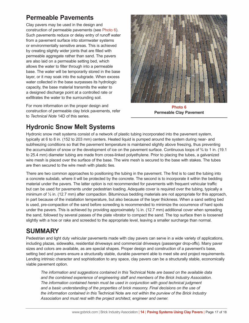
Permeable PavementsClay pavers may be used in the design and construction of permeable pavements (see Photo 6). Such pavements reduce or delay entry of runoff water from a pavement surface into stormwater systems or environmentally sensitive areas. This is achieved by creating slightly wider joints that are filled with permeable aggregate rather than sand. The pavers are also laid on a permeable setting bed, which allows the water to filter through into a permeable base. The water will be temporarily stored in the base layer, or it may soak into the subgrade. When excess water collected in the base surpasses its hydrologic capacity, the base material transmits the water to a designed discharge point at a controlled rate or exfiltrates the water to the surrounding soil.
For more information on the proper design and construction of permeable clay brick pavements, refer to Technical Note 14D of this series.
Hydronic Snow Melt SystemsHydronic snow melt systems consist of a network of plastic tubing incorporated into the pavement system, typically at 6 to 8 in. (152 to 203 mm) centers. Heated liquid is pumped around the system during near- and subfreezing conditions so that the pavement temperature is maintained slightly above freezing, thus preventing the accumulation of snow or the development of ice on the pavement surface. Continuous loops of ¾ to 1 in. (19.1 to 25.4 mm) diameter tubing are made from cross-linked polyethylene. Prior to placing the tubes, a galvanized wire mesh is placed over the surface of the base. The wire mesh is secured to the base with stakes. The tubes are then secured to the wire mesh with plastic ties.
There are two common approaches to positioning the tubing in the pavement. The first is to cast the tubing into a concrete subslab, where it will be protected by the concrete. The second is to incorporate it within the bedding material under the pavers. The latter option is not recommended for pavements with frequent vehicular traffic but can be used for pavements under pedestrian loading. Adequate cover is required over the tubing, typically a minimum of ½ in. (12.7 mm) after compaction. Bituminous bedding materials are not appropriate for this approach, in part because of the installation temperature, but also because of the layer thickness. When a sand setting bed is used, pre-compaction of the sand before screeding is recommended to minimize the occurrence of hard spots under the pavers. This is achieved by providing approximately ½ in. (12.7 mm) additional cover when spreading the sand, followed by several passes of the plate vibrator to compact the sand. The top surface then is loosened slightly with a hoe or rake and screeded to the appropriate level, leaving a smaller surcharge than normal.
SUMMARYPedestrian and light duty vehicular pavements made with clay pavers can serve in a wide variety of applications, including plazas, sidewalks, residential driveways and commercial driveways (passenger drop-offs). Many paver sizes and colors are available, as are special shapes. Proper design and construction of a pavement’s base, setting bed and pavers ensure a structurally stable, durable pavement able to meet site and project requirements. Lending intrinsic character and sophistication to any space, clay pavers can be a structurally stable, economically viable pavement option.
The information and suggestions contained in this Technical Note are based on the available data and the combined experience of engineering staff and members of the Brick Industry Association. The information contained herein must be used in conjunction with good technical judgment and a basic understanding of the properties of brick masonry. Final decisions on the use of the information contained in this Technical Note are not within the purview of the Brick Industry Association and must rest with the project architect, engineer and owner.
Photo 6Permeable Clay Pavement
www.gobrick.com | Brick Industry Association | 14 | Paving Systems Using Clay Pavers | Page 18 of 18
REFERENCES1. 2010 ADA Standards for Accessible Design, Department of Justice, Washington, D.C., September 2010.
2. ASTM C902, Standard Specification for Pedestrian and Light Traffic Paving Brick, Annual Book of Standards, Vol. 04.05, ASTM International, West Conshohocken, PA, 2016.
3. ASTM C1272, Standard Specification for Heavy Vehicular Paving Brick, Annual Book of Standards, Vol. 04.05, ASTM International, West Conshohocken, PA, 2016.
4. ASTM D698, Standard Test Methods for Laboratory Compaction Characteristics of Soil Using Standard Effort (12,400 ft-lbf/ft3 (600 kN-m/m3)), Annual Book of Standards, Vol. 04.08, ASTM International, West Conshohocken, PA, 2016.
5. ASTM D1557, Standard Test Methods for Laboratory Compaction Characteristics of Soil Using Modified Effort (56,000 ft-lbf/ft3 (2,700 kN-m/m3)), Annual Book of Standards, Vol. 04.08, ASTM International, West Conshohocken, PA, 2016.
6. ASTM D2940, Standard Specification for Graded Aggregate Material for Bases or Subbases for Highways or Airports, Annual Book of Standards, Vol. 04.03, ASTM International, West Conshohocken, PA, 2016.
7. ASTM E303, Standard Test Method for Measuring Surface Frictional Properties Using the British Pendulum Tester, Annual Book of Standards, Vol. 04.03, ASTM International, West Conshohocken, PA, 2016.
8. Cooper, R.A., Wolf, E., Fitzgerald, S.G., Dobson, A., and Ammer, W., “Interaction of Wheelchairs and Segmental Pavement Surfaces,” Proceedings of the Seventh International Conference on Concrete Block Paving, Cape Town, South Africa, Concrete Manufacturers Association of South Africa, October 2003.
9. Flexible Vehicular Brick Paving – A Heavy Duty Applications Guide, Brick Industry Association, Reston, VA, 2004.
10. Proposed Accessibility Guidelines for Pedestrian Facilities in the Public Right-of-Way, United States Access Board, Washington, D.C., 2011.
11. Wolf, E., Pearlman, J., Cooper, R.A., Fitzgerald, S.G., Kelleher, A., Collins, D.M., Boninger, M.L., Cooper, R. and Smith, D.R., “Vibration Exposure of Individuals Using Wheelchairs over Concrete Paver Surfaces,” Proceedings of the Eighth International Conference on Concrete Block Paving, San Francisco, CA, International Concrete Pavement Institute, November 2006.