PBEDICrING DRYING TIUES O? SJME BU&MESE WOODS F::>i?. :I'vlO TYP.E:S 01-' SOI.Ah K:ILNS by Win Kyi Thesis suhmit·t~:l to the Fa::ulty of t..he Virqinia Polytechnic Institute and State University in partial fulfillment of the requirements for the degree of MASTER OF SCIENCE in Forest Products Al?PlWVrm: ----;;,-E .. -N .. -'!Jengelt, ______ _ July., 1983 Blacksburg, Viryinia Lamb
Energy Balance Conce_pt .... - ..... _. • .. _... .. 9 Total Energy Input to the System ••••• 9 Tota.l Energy output ............ _. .• • .• • 13 Energy Balances ........... •• 22
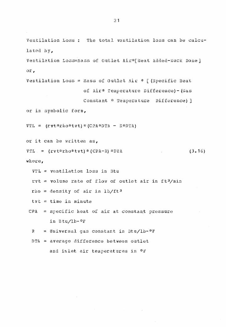
Ventilation Loss ! 'l'he total ventilation loss can be calcu-
la ts::>11 h y,
Ventilat.ion I.oss=Mass of outlet Air*[ Heat Added-Work Done]
or,
Ventilation Loss = tlass of o ut.J.,at Ai e * [ (Specific Heat
of Air* Tem,per:ature Diff,.:,rence) - (Gas
Constant ~): Temp,2ra ture Difference} J
or in symbolic form,
or it can be written as,
VTL = {rvt>l<rho*tvt) ;or- {CPA-B.) ;'<DI'J\.
where,
VTL = ventilation loss in Btu
rvt = volume ra.:te of flow of outlet air in ft 3 /m.in
rho= density of air in lb/ft 3
tvt - time in minute
CPA = specific heat of air at constant pressure
in Btu/lb- op
B = Universal gas constant in Btu/lb-°F
DTA = average difference between outlet
and inlet air temperatures in °F
{3.16)
22
3. 2 .. 1. 3 Ene:r.gy Balances
Using the data obtained for the various energy .input
and the various energy outpu:t for each day, the energy ba-
lance relationships for the kiln can be calculated £or each
day using the follo•ing expressions,
TEI= SETR +ELI+ CDG + EGL
TEO = (TOPL + BOTL) t (F;VA+HYG+]~O.L+CDLf-VTL)
(3. J7)
{ 3,. 1 8)
where, TEI is the total energy input and TEO the total ener-
gy output for a given day, the other ter.l!is are the safile from
equations (3.1) through (3.16).
The energy balance for each day was calculated by,
TET =TEO+ E {3, .. 19)
where,
TEI - total energy input to the syste1n .i;n Btu
TEO = total energy out.put .f-r.-0111 th:e system in B-tu.
E = error
3.2.i Efficiency
The efficiencies o-f the collector (EFFCL) and the ilry-
ing chamber {r;FFDC) can he calc u1ated for each day as fol-
.Efficiency o.f the Collector = (Solar Energy Input to the
Drying Ch,a.mber_} / (Solar Energy
Incident :> n the Collector)
23
Efficiency of the Drying Chamber ·= (E vaporatio.Q. Loss
+ Hygroscopic Loss)/ (':r.otal
oc i:n symbolic forms,
EF.r.'CL = SEIDC/SEIC
.Energy
Drying-
E.FFDC = {EVP+H.YG) / {SEIDC+ELii-CDG+EGL)
wttere,
Iqput to
Cham.ber)
the
(.3. 20}
(3 .. 21)
· SEIC - total solar energy incident on the collector-cover
on each d-a.y
SEIDC - total solar energy input to t.he drying cha-m.ber
on each day
= SETR- {TOP.L+BO'J'.L)
and the other terms are as defined in equations (3 .. J)
through {-3 .. 19),. _.
The overall e:fficiency (EFF) o:f the kiln ·for each day
can be calculated from the equation#
Ovecall Efficiency - (Evaporation Loss + Hyg-roscqpic Loss)/
rrotal Energy .Available tC> the Sy.stem)
or in symbols,
EFF· = (F.VP+HYG} / {TE.A)
or,
EPP= (EVP+HYG}/~EIC+ELI+CDG+EGL)
24
where,
TEA= SEIC+ELI+CDG+EGL { 3 .. 23)
= total energy available to the system
3"' :2. 3 Empirical Egua tio n fQ£ Estimating D.aily Noisture Content Loss
An empirical equation for the overall efficiency of the
kiln can be found a11d t.oget her with etJUa tions for e 1rapora-
tion loss (egu.3.12) and overall efficiency of the kiln
{egu.3.22), daily moisture content loss in percent {HCL) can
be estimated by the follo•ing equation.
In the above equation, the energy required to overcome
hygroscopic forces which are only effective below the fiber
saturation point and are also very small compared to the
evaporation loss, are neglected for simplicity.
Knowing the total solar energy incident on the collec-
tor-cover1 the total energy available to the system (TEA)
can be estimated by,
TEA.= SEIC/R (3 .• 25)
where,
SEIC = total solar energy incident on the co11ector~cover
in Btu
= SI*.ACV
Chapter IV
MATERIALS ARD METHODS
Two types of so.lar kilns were studied .• The main par--
tion of this study was conducted on a prototype external-
co.llector .kiln a.t the u • .s. Forest Products Laboratory, f'ladi-
son, Wisconsin .• For pucpose of coll1pacison, a solar kiln of
.semi-greenhouse type loca tell at Virginia Po.lytechnic Insti-
tute and State University.., Blacks.burg, V.icg.inia was also
studied ..
4. J E.XTERlO\L COLLE£.:!:_OH SOLAR !£.I.1.[
Two loais of green sugar maple lumber were dried during
the summec of 1982~ Thes-e two r:un.s will be discussed sepa-
ratelr, following a .b.:cief description of the kiln itself.
Description of the Kiln
The prototype external-collector solar lumber kiln used
in this study .is located at the u • .s • .p .• A. :Forest P:cod ucts La-
bora-tory, adjacent to the cam,pu.s o.f. the University o.f Wis-
It mainly consists of two
parts, the solar collector and the drying chamber, as shown
·• '!7- .• 1 1.n "' 19 :ure · ...
26
Legend
A - Drying Chamber 8 - Collector C - Blower D - Air Duct E - Circulating Fans Fl,F2 - Humidistats H - Damper Motor J - Fresh Air Duct K - Exhaust Fan L - Thermostat
In this study, the transmittance of the cove~ £or radi-
ation ft"O!!I plate to sky (T} and emm.ittance of the cover- (EC)
for the fibecglass-reinfocced polJt::.Ster were assumed to be
0.2 and 0.8, Cf~specti vely. The plate e:ni ttance {EP) of
granulated charcoal, was estimated to he 0.95.
39
The plate temperature {'l~P) was obtained from thea:-mocou-
ple .number { 13) and tiH~ cover temperature (TC} from the av-
erage of therm:>couple .numbers {11), (12),(14),{15),a.nd (16).
Th,;:~ ambient temperature was obtainea. frorii thermocoupl,e num-
bar (20) ~nd the sky temperature {TS) calculated fcom the
a.mbient te.mpera t.ure (TA.) by use of the formula,
J;verage wind speed. for each day w-as obtained from the
local cl imatoloqical data ohtained from the National Wea the~
Service at DanB County .Regional Airport, about 5 miles far
from the solar kiln.
Bottom Loss : 'I'he concl.uction coefficient (UB) of granulated
cha.rcoal was assumed as o ... 432 9 from
ieast(1967) •. The surfa:e area (APL) of the plate (the char-
coal) was estimated to be 170 .s1;1uare :feet .. The averaqe
temperature difference between plate and ground :was
estimated from the readings of thermocouple numbers (13)
and (24), respectively.
.Edge Loss '1.'he edge loss was ca.le ula tea. using the same
procedure a.s for the bot tom loss ... How~ver, since the total
area. of plate in cont.act with the ed.ge of the collector is
very small, about 2.5 square feet, the total edge loss was
presumed to be negligible.
40
Enerqy Loss from the Drying- Ch.amber The five main losses
from the drying chamber were calculated as follows.
Evaporation Loss: This was calculated from equation (3.12),
EVP = {62.4*V*SG}*(MCL/100)*[0.53{212-Ti)+972]
In this study the green volume of the lumber (V) was
estimated from the dimensions of the boards and the green
specific gravity (SG) was estimated from the moisture con-
tent sections of the 18 sample boards by water displacem~nt
method .. Daily moisture content loss in percent (BCL) was
estimated from the average moisture content of the sample
hoards .. The average ini tia1 te.mpe rature inside the dryer-
was taken from the average values of thermocouple numbers
(3), (4) and {5) recorded at a am.
Hygroscopic Loss· It was calculated from equation (3. 13),
The oven dried weight of the lumber {Wo) was estimated.
from thfo total green volume and green volume s1Jecific gravi-
ty of the lumber. Daily average ini t±a.l moisture cn.ntent
and average final moisture content (Mi and Nf) were estimat-
ed from the daily average i.ni tial moisture content and final
moisture content of tht, .sample boards. It was realized. that
41
the surface moistu.re content is lower than the average mois-
ture con tent.. This causes some er:co.r in the calcula tioas of
hygroscopic los~ However, the surface moisture content ~as
unknown and this factor was neglected in the calculations
based on equation (3.13).
Condu~tion Loss: Co~duction loss from the drying chamber
was calculated from equation {3.14),
4 CDL =I UY *AWi *DTWi *twi + URF*ARF*DTRF*trf
i=l + UFL*AFL*DTFL*tfl
In this case calculation for the conductior;i. losses from the
walls and the roof were similar to that of the conductio.n
gain as mentioned before. In calculating the conduction
loss to the floor, the ovecall heat trans£er coeffient of
the floor which consists 0£ a 4-inch th,ick layer of gravel
was assumed as O.S208 Btu/hr-ft2-°F {Wood Handbook, 1974}.
The average temperature o~ the floor was taken from the av-
erage values o.f thermocouple numbers (3.) _and (4} and the av-
erage temperature of the ground was taken from thermocouple
number ( 17) respectively •.
Energy Given to the Load: Similar calculation as that of
the energy gain from the load as mention;ed before.
Ventilation Loss: It vas calculated from equation (3.16),
42
VTL - {rvt*ch.o*tvt) * (C.P.A - R) *D'T.A
.For this solar kiln, in calculating the total ventilation
loss :for each day, four cases were considered;
1. any the exhaust was on
2,. . The exhaust was off but · tl,e circulati,ng fans and
:blmi1er were on
3,. The exhaust and blower :\we:ce off but the fans were on
4. The exhaust, .fans and blower "Mer~ off
The volume~ rate .of .flow of outlet air (rvt) .for each
case was taken to be,
case {1) 600 ft3/min
case {2) 300 ft3/min
case (3) 250 £t 3 /min
case (4) mo ft 3 /min
The density (rho) an:1 specific he.at of air (CPA) were
calculated at 85 .. 5op and 52 %RH which were the average temp-
erature and relative humidity inside the ch.am.her for tile
~hole d.rying process.. They were t,clke:n as 0,. 7113 ll'.1/cu£t and
Uni -versa.1 gas constant H
was taken as 0 .• 0685 Btu/lb°F .from publislted values.
The total running time (tvt}
from the counters ..
.for each case :was taken
43
The outlet and inlet ai.c tempera·ture.s were taken from
the~ruocouple numbers {4) and (20) respectively.
Calculation of Ene.cgy Balances : The energy balan,ce rela-
tionships for. the lciln were calculated fm: each day u.si:ng
equations (3.17) and (3.JB),
TEl =SETH+ ELI+ CDG • EGL
~rEC = {TOPL + BOTL) + (EV A+HYG+EOL+CDI. +VTL)
and then, the energy balance for each day was calculated b~,
TEI - TEO+ E
Calculation of Efficie11cies : Th.e e.fficiepcies of the co.1-
lec·tor (EFFCL) and thi:-; d.r_yinq- chamber (EFFDC) were calculat-
ed for each day {24 hour period), using e;1uatious (3.20) and
(3. 21), ~1hereas overall efficie.ncy 0£ th.e kiln was calculat-
ed by eguation (3.22).
Empii:ical Modf.ds fo.r: Efficienci-e.s A statistical analysis
system (SAS) was used to indicate which fac·tors explain the
variation in efficienci-es during the drying period of the
collecto.c (El''FCI.) and drying chambe_r (EFFDC), as well as the
overall efficiency (EPF).
linear regression was,
The model used i.n the multiple
EPFICTENCY = f (IMC.,S.I 11 TA,.S\TP.H,VW)
where,
.IdC = daily average initial moisture content
of the samples in percent
SI = daily solar insolationin Bi.:u/ft2
TA = daily average ambient temperature in op
SVPR·= daily a vera91~ sa tun. ted vapor pressure in mm
VW = daily average wind speed in ~ph
N ul tiph:,, linear regression tests using a stepwise
procedure were executed for e.acb. of the three efficiencies,.
Js'or the collect.or effici:ency {Et'FCL} the daily solar
insolation was the significant factor. Therefore a polyno-
mia1 regression test with stepwise riroced ur:~ as well as sev-
Bral exponential .models of collector t::£f.icie.ncy against dai-
ly solar insola tion were tes·ted,.
.For th.e drying chamber efficiency {EFFDC) and the ove-
rall efficiency (EFF) the averag,2 ini t.ial moisture conte.nt
was the significant factor. a. polynomial
regression test with stepwise procedure as well as several
exponential models of arying chamber efficiency {.E.FFDC)
against average initial moisture content (INC) and overall
efficiency (Ki.'~P)
(IaC) were testeda
against average initial moisture content
45
Second £!:}!!1
·rollowing the same procedure as in the .first run,. a
second load of the same thickness and the sa.me length was
solar d.ried again beginning ,July 20_,. 1982~ This test termi-
nated o.n August 15, 1982 after 26 days of drying ..
The purpose of t.liis nm was to test the empirical egua-
tion dcrneloped in t11e first nm for predicting daily mois-
ture con tent loss a_;gains t actual data,.
4,.2 SENI-GREENHOITSE !!bl
For purpose of c o.mpa:cisma with -the pr,evious study of
the external collector solar kiln, a semi-greenhouse type
solar kiln was also studied during the Fall of 1982 •.
4.2.J Description of the Kiln
The semi-greenhouse solar lumber kiln used in this .stu-
cly is .located at Virginia Poly b?,!chnic Institute a:nd State
University, on the campus of the Thomas l'l"'Brooks Forest Pro-
duc·ts Center, Blacksburg-, Vir:g.inia {35°,9'N,8l0 W). :rhe kiln
is 4 feet square by 8 feet high at the north and 4 feet high
at the :sou·th, as shown in Figure 2 •.. ·
It has a capacity of 150 to 200 board feet, with a max-
imum board length of 4 feet. '£ he insidEi and outside Tiilal1.s
are sheathed with. 1 /i~ inch ply:wood and are insulated with
8 FT.
ACC 00
46
~------ 4 FT.-----l' ... 1
7
4FT.
Figure 2: Semi-Greenhouse Kiln, VPI & SU, Blacksburg.
47
4-inch thick fiher glass insulation, including a vapor bar-
rier on the inside face~ The floor is of similar construe-
tion to the walls except that the upper surface is seathed
with 3/4 inch plywood.. The roof is tilt<.-'!d at a 45° angle to
the south.. I-t is covered lvi th two layers of t:canlucent.
'Weather resistant polyester fi:lm spaced two inches apart.
The kiln has one access door on the east ,~all ·to permit
periodic examination of the lumb;er and. measurement of mois--
ture content .. The roof and the south wall are also hinged
to the north wall and to the floor, for loading and unload-
ing ..
The overall heat trans£er coeff~ents £or the Malls1
floor and roof are about 0,. 071 ,and. 0. 51 Btu/
ft2-hr~°F 1 respectively (Oliveira et _g,_,b, 1978) ..
two adjustable vents of about 48 square inches near the top
and bottom of the north wall,.
A one-speed window fan of a.tout O.l HP is also provided
for the circulation of air.
Zill the interior walls as well as ·the fan support plat-
form are painted flat black to maximize the .absorption of
solar radiation ..
48
4.2.2 Ha teria.ls
Green yellow poplar- { Liriodendron tu.J..i.Qif~£i! -1 ... ) ~lum-
ber of a vera.ge thickn,ess 1 125 inc hes was solar dried in
th.is study,. A total of 34 boards were cut in the Forest
Products Center- sawmill from two 8-foot logs and two l0-£oot
logs whose diameters ranged froM 11 to 16 inches.
4.2.3 Exee:rimenta1 Procedure
Each board was marked according to the log number, im-
mediately after cutting. One 1-inch section was cut from
the center of each board in order to estimate its average
initial moisture content and speclfic gravity. 'I'b.e width
and the thickness of each moisture content section were also
measured in order to estimate the tot.a.l green volllille of each
board.
A total of 34 4-foot length boards of different widths
'were stacked in Uu~ kiln, one · from Gach of the original .34
full length boards. 'I'.he width of the pile was only 2 feet
and there were total of 17 layers rna.kiri.g the pi.le a.bout 2 .• 5
feet. hig.h. A sht~et of black-painted plywood was laid on top
of pi.le as a.n absorber. Just before stacking, fou:r. boards,
each from a different l::,gs and of different widths were se-
lected and used as sarnp1e .boards.
49
To get :a comparison, the remaining 34 hoards which were
also 4 feet long and from the opposite ends of the 8-foot
length hoards were also stacked for air drying close to the
solar kiln. Four boards which =ere end matched with the
sample boards in the solar kiln were a.lso used as sample
boards in the air-dried pile.
Bacause of instrument limitations the data collected
for the energy balance calculations wer-€ not extensive as
those for the external collector kila.
Seven -ther: mistors were s12t U? to measure the tempera-
tures at different locations in the kiln. There were two on
the air entering and t;,vo on the air leaving side of the
pile, one just below the inner layer of tl,e pqly2ster, o:rnS!
at the center of the outside-south wall# and one just out-
side the kiln near the top of the north ~all. The tempera-
tures of these thermistors were recordEJd every hour by a Ho-
n,,~ywell strip-chart recorder.
A hygrothermograph was placed inside th,e kiln. to esti-
ma.te Ute relative humidity insicle !:hE~ kiln~ The circulation
fan Mas activated by an electrical timer for the six hours
between 10 am and 4 pm each day.
Both solar drying anc1 air dr:ying wen:~ started on Octo-
ber 6, 1982. A.11 sampL2 boarc1s from both piles wzre weighed
every morning before 9 am, unless it had rained.
50
ture content of each sample then calculated based on
the prev.iously estima·te oven-dried s-eight of each sam;ple
board, in ocder to estimate the average moisture content of
the lumber.
The solac drying was terminated on November 3, 1982
after 28 days of drying.. The pile was unstacked and each
board :was weighed to measure the tota.l .final weight of the
lumber ... · A 1-inch section was cut f.roru tlu?. center of each
sample board to calculate ·the actuc.l final Inoisture content.
The air drying was te.i::minated. on, Novemb,:er 10., 1982,
after 34 days of dry.in9.
4. 2. 4 £.!!~lytical Procedure
Total green volume of the solar-dnied lumber :ilas esti-
matea. from the average thickness,
the boards. Based on the total
l ume specfic gcavit.y obtained
width and the length of
green volu:me and green vo~
by the ~ater displacemeRt
method, the tota.l oven-dried weigb;t of the lumber vas esti-
mated ..
The oven-dried ~eight of each sample board from hot.b.
piles was recalculated based on their actual final moisture
cont.ent obtained from the moisture section cut at the end of
the run~. The average initial and da.il.y .moisture co,nte.nts of
the sample boards from ea.ch o:ile were recalculated based 011 L .
their recalculated oven-dried weights.
51
Daily solar insolation data measQced at a 45° tilt
angle were obtained from the Department of Mechanical Engi-
neering at Virqinia Polytechnic Institute and State Univer-
sity3 Blacksburg, Virginia.
The data obtained in this study were not sufficient to
calculate tte energy balances during the drying period.
Daily solar insolatio-n ~as o.:btaii1ed on,ly for 15 out of the
28 days and the temperatures obtained from some thermistors
were also not correct at some times. For this reason only
thfJ overall daily efficiency o:f the kiln {RFI·") could be cal-
culated ana this only for the 15 days that solar insola tion
data were available. The following equation,
EFF = (EVP+RYGJ/(SEIC+ELI) (3. 27)
§there, thB ,avapor-a tion loss (EVP} a.nd hygroscopic losses
(HYG) were calculated from equations {3.12) and (3.-13); to-
tal solar ener-qy incident on the cover (SKIC) was calculated
by the product of thr~ collector area (22 sguare feet) and
the daily solar insolation in Btu per square feet; total
electrical energy input to the system (ELI) by the circulat-
ing fan was calculated £rom th,?. power con:suIDed by the fan
100 watts (5.69 Btu/:m.in} and total running time 011 each day
(6 hours),.
52
In ca.le ulating the total energy input to the system,
energy gain :by conduction ana. energy gac.in f.com tl1e load Were
neglected in the above equatio~.
Chapter V
RESULTS AND DISCOSSIQNS
The results o.bta.ined on each of the two types of kiln
will be discussed sepa.ra t.ely,.
5 .. J !!T.E!iJi!"!!. C0LI.LECT0R [ill
'the discussion of the external col.lector ki.ln cesults
is divided into th.rea sections. The first sect.ion wil.l dis-
cuss -t:he results of t..h.e ·.first run on sugar ll1aple .. The sec-
onJ section concerns the seco~1d run o~ suga:;c Eaple. 'l'hi3
third .section 1iil1 discuss possible methods to improve the
kilo ef.ficieny.
This section :will include general Qhservations, energy
input., energy output, energy ba1a.nce, ~fficiency, and empia:-
ica1 mode.l £or ef-ficiency for the first run from 16 ~June,
1982 through 14 July, 1982.
5. J .. 1 .. J General Observations
The total green voluBe of the lumber used in this study
was 1040 board feet of sugar maple of 0.58 green sp~c:ific
gravity. Based on the total green volume and t.he grRen Sfn~-
53
54
cific qravity, the total ovend ry weight of the lumber ~as
estimated to be 3137 pounds.
The average initial and final moisture contents of the
18 sample boards were 6Q.4 and 8.0 percent, respectively.
The total drying time was 29 days and the average daily
moisture content loss was therefore 1.94 percent~
ing curves based on the average for 18 sample boards togeth-
er llli th those for the 9 sample boards each on the air enter~
ing and leaving sia.es ot ·tht: pile are s:hown in Figure 3 ..
Daily average initial and final moisture contents of 181
boards in the load were estimated using the average of the
18 sample boards. There was some variation o.f the moisture
content among the sample boards especially at the beginning
of the run .•
Average £inal moisture content obtained from 9 boards
taken from different positions in the pile at the end of the
run vas 9.7 percent with inaividual values rang~ng from 8.9
to 10.3 percent. The average final moisture content was 8.Q
perce'fft which was based on the 18 sample boards ..
:rh0 i1istribution of moisture cont!:~nt in the load can
also be estimated from the two drying curves .based nn the
sample boards on the a.ir entering a .nd leaving sides of the
pile ( Fig.J ) •. • At tln::; .'hegj_nn.ing of the run, the average
drying rate of the :samples on the ai.r-en ter ing sid{~ was
85
60
55
so
us
uo
ss ti
C 30
X
2S
20
15
10
5-
0
side
erage
Entering air side
11. I •• I. 'I I I I' I I •• ii I. I •'l""J'"""W'T~-r- ••• I • i ~. • I ii I. I .... J'T""'T'....,.__., I I" .. I" •• I ii I'." I I.' I I.. 'I. I.. i' I I I I" 'I .. I I I I I" I
0 2 S U 5 6 7 8 10 II 12 13 1q 15 16 17 18 19 20 21 22 23 2ij 25 26 27 28 29 OATS
Figure 3 Dryirig Curves of Sugar maple, First Run .•
l11 IJ1
56
higher than that of the samples on air~ leaving side.. Howe v-
er, afte.r 7 days the average drying rate of the samples on
the air:~leaving side became faster than Uiat of the samples
on the air-en:tering side,. At the end of run, -t.h.e average
moisture content of the sample boards on hotil sides oft.he
pile was within o .. 4 percent moi.sture co.,ntent.
As m~ntioned earlier, the total ove.:wlry weight of the
lumbe.r 'i,l,as estimated initially from th.e total greeu volume
of the lumber aud the average green speci.fic gravity of the
sample boards.. This calculatio.n is subjected to err:o.r,
since the tot.a.l green volume was calculated from the dimen-
sions of each hoard. As a check~ the total ovendry weight
of the 1 umber cal.culated from the a v,arag~ ·.final moisture
content ( 9. 7 Yi } obtain.ad f r-o:m the 9-boa.rds and the total
final w1:.1ight o;f 181- !wards which Ji1as 3·45.3 pounds, :was .3148
pounds,.. This is within 0 .. .33 percent of ·the tota.l ovendry
weig~t 3137 pounds which had been estimated based on the
specific gravity and green volume measurements. The best
method to es·timate this weight would be to devise a system
to measure the total weight of the whole pile at any time,.
The average daily solar insqlati.on du.ring the dryi:i1g
period was 1906 Btu/ft 2 ., and ranged from 5·12 to 2736 Btu/ft2 •
There were total 0£ 11 :rainy days resulting ill. a total pre-
cipitation of 2. 42 ir1ches.. '.fh.e avera.g,e amhient tcrnrperature
57
during the arying period was 67.5°F and ranged from 46.0 to
Other climatological sta ti sties which are be.lieved
to be import.ant are given in Table 1 ..
'Jl:he average temperature and. relative humidity inside
the drying c.hamher during the drying period was 85,. 5°.F and
.52 percent, and ranged from 60.0 to 117.0°P and 26 to 90
percent, respectively.
The average temperature o~ the air inside the collector
was 78.6°F with lower and upper limits of 46.0 arid 119.5°P~
That of the plate was 82 .• 8°:F and ran9ed from 46 .• 5 to
138 .• 5°.?;e.
The average daily total po,wer consumption by the circu-
lating fan, blower and exhaust fan was 13.7 Kihr1 ranging
from 7.0 to 22.5 Killhr.
5.1.1 .. 2 Energy Input
The total energy input for each day, calcu.la ted from
the total ener9y transmitted through th,e collector-cover is
given in Table 2. The total errnrgy input component.s for
the whoLe drying process are also shown in Table 3
Table 4 indicates the total da~ly energy potentially
available to the system iricJ.uding tln::.? total solar energy in-
cident on the collector cov(~r.. Tabh, 5 sho~rs the components
of the ener:gy potentially available £o_r the whole drying
period,.
58
TZI.BI.B 1
Variables and CoBfficie.nts for the First H u.n of External Collector Kiln
r·------------.---------------1 Varia.b1es or J Coefficients J-I
Unit
I
I i1ean l . ' I
l riinim.umJ Naximumj j J l
}Daily Solar Insola- I Btu/ft.2 l l :1 j
,j 1906j
I 6,.. o I
I 5121
j 1,. 61
I 46. 01
7,. BI I l
26,. Ol j
D,. 31 I
I 27361
1 tion l n J J A mhient Tempera tun=: ! u n
I I Ambient JRelative Humidity j JAmbient Saturated )Vapor Pressure I n u ,.
I !Pr,ecipitation I H
'l jWind Speed I ;f H
f )Chamber Temperature
j l I j l I I ij I i l j l I l l i J l l
j n n j 1 l JBelative Humidity i I {inside the Chamber) j J i JCollector Temperaturej
·n n j
!Absorber Temperatuce l 11 u l !Solar Energy Input 1 " " " j
I I l j J i !
jElect:cical I n
.Bnergy I11pJ H ff j
# KBtu = 1000 Btu
KW-.hr/m2
mm-Hg
J I j l j i I j l i
j_nch.es/day j mm/day I
mph Km/hr
l I J J I 1 J I j I l i
' I 1 i
KBtu/day f, I KW-hr/day j
KBtu/day KW-hr/day
l I I
I 67,.51 19. 7J
.j I
62.0j I
O, 611 l
Hi. 96J I
0.221 5.59j
I 8.62j 3 .. t35j
j 85.Sj 29 .. 7j
.i 52,.0j
j l
7 8 .. t:> I 25 .. 91
j 82. 81 28 .. ?1
I 254.,.61
74. 61 I
40,.0j l1. 7 j
1 7.971
I o,.03l 0,.76)
J 4.201 l.88l
i 60 .. 01 15 ... 6 l
I 26. OJ
l j
46. Gj 7 .. 8 I
j 46,. 5 l
B .. 1 i l
68 .. 41 20,.01
l 15,. 6 j
4 .. 6 J
i B. 6J
,I 87,.0} 30. 6 i
a l
92,. OJ i
1.26j I
32 .. JO J j
o .. 42 i rn. 6 7 l
I 15. 10 I
6.,751 I
117.0j 47 .. 2l
j 90 .. D j
j i
119, .. :3] 48 .• 6 j
j 138,. 5 j 59. 21
j 365 .. 61 107.0j
j 6fJ. Ji .20. o l
Variables or Coefficients
} JTotal JPower I H
EL.?.ctrical Consumption
u
l I Total I u
Energy Input n ,n
,J )Total Ener:gy Output. I H H 0
J }Difference in Total JEnergy Input&Output I u " « ! ]Heat Transfer Coeff: I bet: Pla be> t; cover .) 0 H n u
l JRadiation Coeff:from !Plate to Cover j n u a o n u j jRadiation Coe:ff: from j Cover to Sky l n n n u
I JWi11d Coeff: j n n
l )Top Loss Coeff.: I u 11 u
i L
n
# KBtu = 1000 Btu
l j j I j j I I l I j
l 1 J j
l j I j l I J l J J l I J J I ! I I
59
TABLE 1
{continued)
Unit
KBt11/day :/j:
KW-hr/day
rrntu/cl.ay KN-hr/day
KBtu/day K~v-hr/day
Btu/d.ay
KW-hr/day
Btu/ft-= o·"' ;{'
J.;Jjm2 oc
Btu/ft:2 op
W/m2 oc
Btu/ft2 o:~
W/m 2 0"' ....
Btn/ft 2 Op W/m~ oc
Btu/ft2 oy W/m 2 oc
l I l I I i I I I j j l I
' 1 l I 1 I f I i I l j 1 i ! I i 1
Hean 1 rlinim um l l"la ximum] l I I I i f i I J
46 .. 91 23.8J 76 .• 9j 1 I J
13.7) 7.0J 22.51 I J l
300.01 120.0J 433.6J 87.91 35.2] 127.0j
I I l 299 .. SJ 172.QJ 429.0J 88.lJ 49.61 126.11
i j j 580j 30001 89,000,j
l I l 0.221 0.021 2.61j
l J J 0.221 0.19j 0.27j
J j j L27J 1 .. Q.81 1.54j
I J J 0.831 0.741 0.91J
I I J q.114 4.191 5.14j
I l I 0.761 O.ij81 Ob84j
i J I 4.33) J.84J 4.751
I I J o.681 o .. 33J 1 .. JJJJ 3~85j 1,.88) 6.75j
1 I I B.521 7.61,) 9 .• 90! l.'.;>Oj 1..341 1 .. 751
I I I
TABLE 2
Daily Tota.l Ene:cgy Input
r--T :l D l Daily i 'fotal I Total I E.n.ergy I Energy I Total J I I Sola.r 1 Solar 1 :i~lec- fGain bYI Gain from ,j ,I ) .A Un.sola-1 Energy I trical I Con.due-) t:11e Load j Ene;cgy i I · I tion JTrans- j .Ene:rgy .j tiop. ;I j 4 I 'l I lmitted I Input j ) :I Input J l J Btu/ft2 i {KBtu) J (KBtu) j {K.Btu) j (KBtu) ;f1: I (KB tu) j :r--· j J I J i I i ) 1 J 2736 I 366 I 64 I 3 j j 4.33 .
. I t '"I
.;f. j 1224 J 163 I 64 I 1 I t 228 J l 3 I 1095 I 146 I 50. i 0 J 24 j 221 J I 4 I 2415 I 323 l 68 l 3 j J 393 l I 5 j 2182 J 292 I 67 J 1 l 1 .]60 I j 6 J 2223 I 297 j 67 j 1 J J 365 I I 7 .I 2534 I 339 I 68 j 3 J j 409 j I 8 J 2232 j 298 l 68 l 2 i j 368 I l 9 J 2316 I 309 j 66 I 1 l i 377 I J10 l 512 l 68 l 18 I 0 ff 36 I 122 l J 1 1 J 2-009 I 268 l 32 I 2 J I 30,2 j 112 I 1391 j 186 I 29 l 3 J j 217 j. ]13 J 1894 l 253 J 33 l 3 I j 289 j I 14 I 817 I 109 I 18 I 0 . 23 l 150 j J 115 t 2538 t 339 i 32 j 2 1 j 37:) I !16 I 2443 I 326 J 36 J 1 I I 364 I J17 I 1354 I 182 J 26 ,t 0 l 3 ) 211 .i 118 1 1304 I 174 I 28 J 1 l I 203 i I 19 1 2597 I 347 J 43 I 2 i ! 393 j J20 l 233.2 J 312 I 38 j 1 i 7 t 357 I j21 t 761 J 102 j 19 I 0 J 16 1 137 l 122 ! 2607 I 348 I 30 I 1 l I 379 l 123 l 2507 l 335 l 33 t 2 I J 370 j 124 .J 1765 I 236 J 26 j 0 1 4 cl .266 I J25 I 983 J 131 .. J 16 I 0 I 7 j 154 j j26 1 2116 j 28.3 I 25 j 0 j .I 308 1 127 j 2285 I 305 I 32 J 1 l j 339 i J28 I 1980 i 265 J 31 j 1 I J 291 I )29 I 21'15 J 283. j 33 I 1 I 2 l 319 I I J J I j I l j L- J
# KBtu = 1000 Btu;
61
ComponHrd:.s of Total .Energy Input
r------------------------------..------'.} I ) j f-l
Source
] Solar Energy Transmitted through J I the Cover J J Electrical Energy Input by the Fans 1
j a I ,j
j j l
J Electrical Energy Input by the Blower) I I Energy Gain from the Load+ J I Energy Gain :by Conduction f-1 I Total Energy Input a # KBtu = 1000 Btu
a I
l I J
Energy I Input jPercent j (KBtu) # .I 1
71384
775
386
122
35
B,702
-f l i I 8 1L,9 I J l I i i l 1 8. 9 l j J l 4. 4 i I l I 1. 4 I I l j 0,. 4 j
1 J l i 100.0 l I .t
+ solar and electrical energy stored in the load
62
'TAB.LE 4
D:ai.ly Total Energy Potentially A vai.lable to system
T 1 J DJ Daily I Total j Total I Energy A Energy I Total j
I I Solar I Solar i ,Electr i- JGain by·t Gain from l Energy 1 j AJ Insola-1 Ene:rgy jcal Energy l Co nduc-,jthe load j Avail- j J J tion I Incide.ntj Inpu-t I tion j I a.ble j j YI Btu/:ft2 I (KBtu) I {KB:tu) J (KBtu} j {KBtu) i j {KBtu) J f--I j 1 I J j J J I 1 I 2736 j .f.1.57 I 64 j 3 i j 524 I J 2J 1224 j 204 ,J 64 J 1 J. I 269 j J 3) 1095 .I 183 I 50 j 0 j .24 t 257 I j 4J 2415 J 403 ) -68 t 3 l· I 474 J I 5j 2182 I 364 J 67 .I 1 J ,I 43.2 .I l 6J 2223 I 371 I 67 I 1 l J 439 l 1 71 2534 J 423 j 68 I 3 j j 493 J J 8] 2232 j 373 J 68 I 2 l J 44.2 j I 9J 2316 I 387 I 66 j 1 I l 454 J I 1 OJ 51.2 I 85 I 18 J 0 I 36 J 139 j .J 11 J 2009 j 33.5 I 32 J 2 I j 369 I j 12 j 1391 J 232 j 29 .I 3 I l 264 J j13] 1894 J 316 I 3.3 ,j 3 I I 352 I J 14 J 817 I 136 I 18 I (l .I 23 J 1TJ -1 1151 2538 J 421-1, J 32 I 2 J l 4.58 j
'.1 16 I 2443 ) 408 j 36 I 1 -i J IJ46 j J 17I 1364 J 228 I 26 I 0 1 3 l 257 j J 18 I 1304 I 218 J 28 i 1 l 1 246 J J 191 2597 I 434 I 43 ' 2 I J 479 J 1201 .2332 j 389 j 38 j 1 j, 7 ,I 435 J J 21 t 761 I 127 j 19 I 0 J 16 I 162 j j22J 2607 j 4.35 J 30 j 1 I l 467 I J2Jf 2507 I 419 J 3.3 J 2 I i 453 1 I 241 1765 J 295 l 26 I 0 d 4, J 325 .i J25j 983 J 164 l 16 t 0 l 7 j 187 I 1261 2116 j 353 l 25 l 0 l a 378 I )271 .2285 J 382 I 32 J 1 j 1 415 j 1281 1980 j 331 I 31 J 1 l 1 363 I ]291 2115 j 353 j 33 I 1 I 2 I 390 j g I j j J j I I :L y
# KBtu = 1000 Btu;
63
Components of 'Iotal E.nergy Potentially Available
J I I t J
Source j
I j
j Solar Energy Incident on the Cover I I I 1 I i j j
i
Electrical Energy Input by the
Electrical Energy Input by the
Energy Gain from the Load•
Energy Gain by Conduction
Fans
B.lower i j j l I
J Total Energy Potentially Available j L
# KBtu = 1000 Btu
Energy Input {KBtu) #
91231
775,
386
122
35
10,549
+ solar and electrical energy stored in load
jPe.rcent I
l I 87 .• 5 l I T.3 j J 3.7 j I l. 2 l I o .• J
100.0
l J j
·1 j i J j I I I I i I l .I i I
64.
It can be seen that the t.o·tal incident solar energy -was
87 .• 5, percent of the tota.l energy supplied, whe·reas the total
electrical energy consumed :was only 7 •. :3 per:cent of the to-
tal.
5 .. J. J .. 3 Energy Ou-tput
Total daily l1eat losses :from the collec·tqr and ce>nduc-
tion losses from the drying cha.l!lber are given in Tables 6
and 7 • The values of heat transfer coe:f.ficient between
plate and cover, radiation coefficient from _plate to cover, -
radiation coe£ficient 'from cover to sky and w.ind coefficient
are also given in Table 1. Tah:le 8 indicates the total en-
ergy output .from the system for each day w.hereas Tahle 9
shows the total energy output components for the whole d.cy-
ing process. __
Prom Tab.le 8, it can he seen that the veQ.tila-tioJ1 loss
was highest on rainy days, a:nd also Oil days towa.cd the end
of the run,. It was the largest of component of loss, av·er-
agin.iJ 36 percent of the total energy output {Tab.le 9) ..
According :to Table 9, the total energ_y used .in the sys-
tem for the ,entire drying proct0:ss was about 8 .. 7 millio.n Btu.
The tot.a.1 amount o-f: water evapo.rab?.d during t.he drying per-
iod was about 1770 pounds.
the system were requ.irecl
from the wood.
Thus, about 4900 Btu input to
to evaporate one pgund of water
65
TllBL.E 6
Daily :rota.1 Heat LOSSBS f r:om the Collector
r l D J Conduct.ion Loss J Top Total Heat LOSSBS j l A t to ·the Ground I Lo.s:;5_ 1 f.rom the Collector I J y I {KBt. u) j {K.Bt U) ! (KBtu) it j f-J I l j l I 1 t 26 i 1 1B I 147 I I 2 l 9 l 66 I 76 i l 3 l 2 j 60 j 61 j J 4 i 26 l 105 I 131 j j 5 l 24 j 96 I 120 J l 6 l 23 i 94 I 1 17 j I 7 .I 30 l 108 l 138 l j s I 24 j 71 t 95 i J 9 l 30 I 81 ' 112 l a 10 1 5 I 59 l 64 j I 11 l 19 I SJ l 10.2 j I 12 l 22 I 54 j 76 l l 13 I 33 I 68 1 101 l 14 l -6 I 48 I 54 1 j 15 I 29 I 100 ! 129 I I 16 I 29 j 96 l 124 I I 17 l 20 ! 72 l 9.2 J I Hl J 20 I 65 l 85 j I 19 l 41 j 98 I 139 I l 20 l 32 I 85 I 118 I 1 2 :1 i ·12 I 58 I 70 I ) 22 J 30 l 104 .J 134 j J 23 j 32 I 109 I 141 J j 21.i I 26 I 74 'JOO j I 25 J 15 1 60. I 74 l I 26 t 25 l 85 i 110 J I 27 j 33 l 90 l 123 ! J 28 2 29 l 70 j 99 J I 29 j 28 1 84 112 i 1-1 l I j I l ~cot- I 679 ' 2,360 i -3,039 j
a al J I l i
# KRtu,=1000 Btu
66
TABLE 7
Daily Conduction Losses from the Drying Chamber
.--,---------...-----.-·-----------...----,.-----. I D J East I A J Wa.ll I J Y J(KBtu)j J---· i 1 I J 2 l 1 3 J I 41 I 5 J I 6 J J 71 l BI .J 9 l I 10J I 11 I J 12 ,i ·1 13 l f 1 4 i l 15 I I 16] i 171 l 18 J J 19 J I 20 i J 21 J J 22j J 231 i 24J J 25) l 261 1 27 I ,t 28 I J 291 i-i j I TOT I I AI.j j 1
1 .. {) J o. 6J 1. 3 j o. 8j l. Jj 1. 5 J l. 6 i 1. 31 l. 21 1. 5 I 1. OJ o. 81 o,.s1 1"' 6 J 2 .. 1.f J 2 .. 9j 2 .. Ji 2 .. Oj 2 .. :5 j 1. 5J 1,. 71 2. :2 l 2.HJ 2. 2j 2 .. 01 2. 71 2. 71 2. 1 i 2 .. ;ij
Southl iest j North i Roof !Floor j Total Wall j Wall i Wall i I I
{I{Btu) I (KBtu) i (KBtu} J (KBtu) #i {KBtu) j
o .. 9 J o .• $ l 1.21 1. o I 1.01 1. 2 I 1 • .iq l,. lH 1 .• 3 I 1,. 4 l t. 2 I 1. o I Oco 9 I 1.,51 2.21 2. iq 2"' o I 1. 71 2. 1 J L. 9) 1,. <3 I 2 .• 0 J .2 • .31 l. 6) L9j 2. 1 j .2. O I 1. HI 2 • .2 J
I 46. JI
I
0~ BJ L.,01 l. 3 j 1 .• 01 l .. :2J 1.-6 J l .. 8J 1,.,5 I 1 .. 8 J L,61 1.01 0.9j o. I 1 ... 71 2. 3t 2 .. 8 I .2 • ...3J 1 .. 91 2 .. Jj 2.21 2.0j 2 .. 1 I 2 .• 5 i 2 .. 3 I 2 .. o l 2.21 2 .• 71 2 .• 1 j 2., 61
I 52. 3 i
J
1. l J o. 7 i 1.3 j 1,. 01 1. 3 l 1. 8j l .. 91 1 .. SJ 1,. /¾.J l. 6J 1 .. 0 J 0.9 j o .. ~) 1 .. 6j .2. 7J 2. $.i 2. lJ 2 .. UI 2 .. Hj 2. 51 1 .. 7 J 2 .. q. l 3. 1 J 2.11 1.9j 2. 8j 2. 8J 2.21 2,. 6 i
J 54 .. 6j
I
O.oj -.0, .• 5 j 0.6J {),. 5 J O .. BJ o. 9 j 1 .. 0 i o. 9 J o .. 71 o,. 81 o. 6 j o .. 51 0.6j o,. 9 l 1 .• 3 I 1 .. 5J 1,. H 1. Oj 1,. 2J 1 .. 11 0'9 9 I 1. 1 J 1 .• 2J 1. OJ 1 .. 0 J 1. 3 I 1 .. J j 1,. 1 j 1 .. 2 I
7 .. 9 I 4 .. 51 O .. -5 I 4 .. 71 4 .. 0.1 4,. 1 J 5 .. 8 I 7.BJ
8 .. 0 I 10. J 13.0 l 15.5 J lO. 7 J 23.3 I 28. 1 j 19. 8 j 19. 2 j 29 .. 7 J 25.4 i 12 .. 6 1 21. 2 j 26 .. 9 l 22 .. 6 I 15 .. 4 i 2 L, 2 i 24 .• 1 I 21,.5 i 25 .. 1 l
l 494 .. 7 l
i
# KBtu=1000 Btu
67
'1:llBLE 8
Daily Total Ewergy Output
r--., ---ID I Evapo- !Hyg·rosco- j Venti-}Cond uc- JGi ven JCoLl.ector l '.I'otal l JA Ira tion j pie jlationl tion j to J Losses I Energy j aY I Losses I Losses j Losses j Losses I load I J cutputJ I j (KBt u) l {KBtu) l (KB tu) I {KBtu} l (KB tu} { KBtu) # j (KBbl) I 1 j j l I I j I I i I j 11 185 j j 73 I 12 l 16 j 144 I 429 I l 2j 128 3 I 45 j 8 j 3 I 75 j 260 I I .3 J 92 i I 83 j 6 j - i 61 J 242 J J 4j 1.25 1 I 56 I 9 j 16 1 131 I 337 I j 5 .I 135 t J 79 I 9 j 4 I 120 j 347 j 1 6j 125 I j 73 I 11 j 7 j 117 j 333 j
l 71 131 I j 86 J 13 I 4 I 138 j 372 l I BJ 112 I l 48 J 14 I 9 J 95 J 278 I J 9 I 112 I l 5.2 l 17 l 11 j 112 j 304. l I 10 ! 23 I I 101 ) 8 I - j 64 J 197 j l 111 89 ] 1 i 65 I 1 1 I 19 I 102 j 287 l I 12J 56 1 1 I 71 I 13 ,, ll I 76 l 227 j 1 j 13 .I 56 j 1 l 46 I 16 l 5 l 101 j 224 l I 14 ! 33 1 1 l 107 I 11 J - 1 54 I 204 i I 151 72 I 1 J 102 i 23 1 25 I 129 I 352 j 1 16 ! 68 I 2 I 129 l 2fl I 2 ! 124 j 354 I j 17 I 29 I 1 I 72 I 20 i - I 92 I 214 j j 18] 29 i 1 I 77 j 19 I 4 I 85 l 215 j I 19) 62 l 3 i 167 l 30 l 12 I 139 I 412 j 1201 39 I 2 I 149 J 25 I ,_ j 118 j 334 l J 2 1.i 10 I 1 I 119 l 13 1 ·- I 70 I 212 i I 221 29 1 2 J 151 I 21 1 11 i 134 I 348 1 ., 23 J 33 I 3 I 203 I 27 I 4 J 141 I 410 j i 24 j 16 l 2 j 151 j 23 l - j 100 .i 291 J 1251 7 I 1 l 76 l 15 l - I 74 j 172 j l 26J 13 J 1 .i 149 j 21 l 7 I 1 10 I 303 j i27J 20 J 2 l 184 i 24 i 2 I 123 j 355 j J28f 13 j 2 l 191 j 22 l 2 l 99 a 328 I J29t 10 I 1 I 196 l 25 t - l 112 j 344 j ;j I I I i i J I j
# KBtu = 1000 Btu;
68
TABLE 9
Compone11ts of Total .Energy out.put
l I .Energy J Delivered I Total J Sou.rce I Re~1 uiremen t 1 to, the Ki.ln I system j J i {KBtu} if j (Percent) I (Percent) t l I j J 1 .l .I Evaporation Loss I 1,851 I 32.. 8 l 2 1 • .3 j a J a I J .I Hygroscopic Loss i 28 I o.s j o .• 3 j I j j J j I Energy Given to J l7tl J 3. 1 j .2,. 0 l l the Load I l J I J J l J ' I Ventilation Loss j 3,099 j 54 .• 8 j 35 .. 7 j J i j J I 1 Conduction Loss J ;4:95 ij 8.~l l 5 .. 7 I j {Chamber-} j j j j I j J I I l Conduction Loss j 679 j J 7,.B I I (Coll,ector) J I l I I f I 1 J I Top Loss I 2,360 .l I 27,.2 ,I I (Collector) I j .J I f---I J j I .I j Total Energy output j 8168-6 j 100. 0 I 100,. 0 I I l J j l L
·J KBtu - 1000 .Btu
69
Based on the total energy consumed ~n the drying ··-
ch amber (not including collector losses) about 3190 Btu {Ta-
hle 9) were .reguiH3d to evapo,,rab:j one. pound of 'il!ater from
the wood. Accocding to Taylor (1982) the energy reguired in
a 12{l0-bd.f t capacity e.xper.i mental steam-heated kiln rangt":!d
from 2259 to 2590 Btu to evapqrate one pound of water from
the southern pine dimension lumber. He indicated that the
energy required decreased slightly with kiln tempt3i·ature
ovec the range from 175 to 240°F. Co.mpar2d to that co.nven-
tional kiln 1 the drying chamber used in this study was about
81.50 percent as e£ficient as the conventional kiln.
Energy Balance
The energy balance for each· clay, based ori the data oh-
tained for total energy input and total energy output for
each <lay (Tables 2 & 8), is given in Table 10. The differ-
enca in total energy input and total energy output per day
for the whole drying period ranged from -7.5,00D to +89.,000
Btu. A negative sign indicates tha.t tlH? calculated dai.ly
total energy input was lower than the output £or a g~ven
day,. These daily differencfaS ar·e caus<?d by errors i:n calcu,-
measuring teraperat uces and d.aily solar insolation as well as
daily moisture content losses.
70
It can also be seen from Tables 3 and 9th.at difference
between the total energy :input and out.put for tue system :was
only 16#000 Btu~ Thus. the average difference £or O¥e day
was only about 580 Btu, only about 0 .. 2 percent of the daily
energy ~nput or output, indicating that the daily errors es-
sentially cancel out.
s .. 1.1.s J~f:fi ciency
The efficiency of the collector and of the drying cham-
ber, and the overall efficiency of the kiln, together with
daily solar insola tion, average initial moisture content,
daily average ambient temper at ur:-e, daily a verag£~ .saturated
vapor pressure and the average wind .speed are given i11 Table
11 •
Th,~ average efficiency of the collector was 4LJ.., 8 per-
cent ranging from 4.6 to 54.4 percent~ That of the drying
chamber was 3.2. 0 p,.?rcent and ranged from 5.3 to .83. 7 per-
cent. The average overall efficiencs of the kiln :was 17.4
percent with a range of 2.0 to 47.7 percent.
Empirical Model for Efficiency
i:1ul ti ple linear re9ression tests indicate that the ef-
ficiency of the collector (KFFCL) was significant.ly related
71
TABLE 10
Daily Enecgy Balance
DjDa:ily I Ini- lFinal I l"IC J To·ta1 J 'rotal JDif.ference i.r;q )Solar Jtial.l I I Energy !Energy J Total Energy I
Atinso- ! MC I MC iLosst Input I :outputjinput £. '.l'otal I tlation t l J J I l Energy outputJ
Yj {Btu/f t 2 } I {)'t) 2 (%) J ( %) j (K.Btu} I (KBtu} 1 ('.KBtuJ # i ·1--· I j l j J 1 I I j I 1 J 2736 j64 .. 4!58 .• 8 j5.6 I 433 j 429 j 4 I
:1 21 1224 . l 5 8 • G I 5·4. J] .• 9 I 228 I 26,0 ! -32 .... I . .,. I 3} 1095 I 54,. 9J 52 .. 1 j.2,.8 j 221 j 242 j -.22 i ,J 41 2415 J 52,. 1148 .. 1 14,. 0 I .393 . l 331 ,1 56 l I 5j 2182 J 48 ... 1 I 44,. 2 f3.9 f 360 I 347 l 13 l I 6j .2223 1144,. 2 i 40,. !¾ j 3 .. $ a 365 j 3.33 J 33 J l 71 2534 140.4J36.4 I 4,. 0 l 41).9 I 372 j 36 I j 8 I 2232 I 36.4 J.33 .. o J 3 .. 4 I 368 I .278 J 89 a I 91 2316 I 3.3. 0 J 2 9 .. 6 I 3,.4 I 377 I 304 I 7.3 I 11 O I 512 I 29,. 9 J.28. 10.7 j 122 l 197 I -75 .J f 11 l 2009 j28.9J.26.2 J 2, • .3 I 302 I 287 i 16 j 1121 · 1391 126.2)24.5 J 1,. 7 a 217 I .227 J -.9 j
• 13,1 1894 I 2lt,. 5 J 2.2,. ? J ·1. 7 ) 289 i 224 a 65 1 I 141 817 122.0121. ,I 1.. {) j 150 I 204 J -55 I PSJ 2538 121.8119.6 ]2.2 I .373 J 352 I 21 J I 161 2443 j19,.6,J17..5 i 2 ... J j 364 I 354 I 1 Q. j I 17J 1.364 117 .• 5116. 6 I 0.9 i 211 j 214 J 3 J I 181 1304 J 16 .. 6 115 .. 7 Jo .. I 203 J 215 j --12 J ,I 19j 2597 l 15. 7 i l],. 8 11,.9 I 393 l 412 I -20 I ,J 20 1 2332 i 13 .. 112 .• J 1. 2 J 357 I 3.34 I 24 1 J 211 761 I 12 .. 6 J 12,. 3 I 0 .• 3 cf 1.37 ,i 212 .I -75 j j.221 2607 112.3111.9- JO,. 9 J 379 j 34-8 J 31 j j23i 2507 I 11 .. 4110.iJ, I 1 .. 0 I 37:0 1 410 j -4-0 J )241 1765 J 10,.lH 9. '9 I 0.-'5 I 266 I 291 l ·-26 j 1.2s 1 983 I 9 .. 9 J :9 .• 7 .) o. 2 J 154 j 172 t -18 1 J 26 I 2116 I 9. 7 I 9.3 ) o. 14 j 30!3 I 303 a 5 I 1211 2285 I 9.31 8.7 J 0 ... 6 I 339 j 355 j -17 I I 28J 1980 l a .. 7 .I 8,. 3 Jo. 4 I 297 I 328 j -31 1 )291 2115 J 8.-;jJ 8. 0 I 0 ... 3 i 319 J 344 I -:25 J j 1 I I 1 ,1 j J J t.
* negative sign indicates that ene,cgy inpu:t is lower than energy ou-tpu·t; if KBtu - 1000 Btu
TABLE 11 Daily Efficiency of External Collector Kiln
D Daily Initial Average Average Average Collector Chamber Overall Solar Moisture· Ambient Sat, Wind. Effi- Effi- Effi-
A Ineo-· Con tent Temp: Vap, Speed. ciency ciency ciency lation2 Pr,
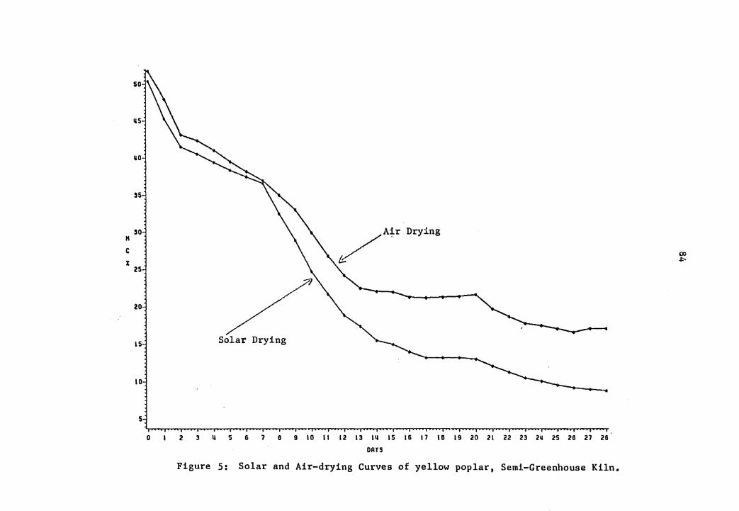
Figure 5: Solar and Air-drying Curves of yellow poplar, Semi-Greenhouse Kiln.
lio .i::-
Ba.sed on these results, it ca.n be seen that lumber can
be solar dried during the fall in Blacksburg (35°9'N,81°~
to a final moistm:e content beloN 10 p,ercent while w-it.h
ai:c-,dr: yin9 it was impossible to attain a fina.l mo.is-ture con-
tent much belov 15 percent.
i'he average daily solar i:nsola tion (9nl_y for 15 days
for which data was available) measured at a 45° tilt angle
to the south :was 1B16 Btu/ft 2 and :r-a.n,gt.~d from 512 ·to 2736
Btu/ft2. _
'1'.he maximum temperature attained in the kiln was a.bout
112.5°P, while the minimum relative hum~dity was about 22
percent. The minimum and maximum tem_:perature of the ambie:n-t
during the who:le drying period was 19°F and 82°£ respective-
ly ..
The average dai:ly power consumption by the c.irculation
fan was 0.6 KWhr, cor:-cesponding to 2048 Btu per day.
s.2.~ Efficiency
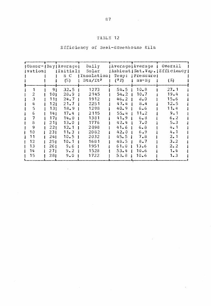
Table 12 indicates the dai.ly overall efficiency of the
kiln .for 15 out of the 28 days of dry.ing., together cwit.h 0th-
er statistics. The average ove:call efficieucy 0£ the kiln
was ca.lacula ted to be 8 •. 3 percent.. However., this value is
not a good indicator- since the calculations :f,or the e.f·fi-
cienc_y was only started f :com. day 9 when ·the averag~ moisture
86
content of the lumber was 32.5 percent {Table 12),. If t.he
calculations include th:e whole drying per-iod,
efficiency would undoubtedly b~ higher.
the average
5. 2 .. 3 ~m 2iri@!. l'1 ode l fQ!: the E f.:fici en:£!. Q.f th~ K~l!l
"J?ollowing the same procedu.ce as was u:sed for external
collector :k.iln, an empirical model for the overall efficien-
cy { EF-P) o.f the semi-greenhouse kiln -was obtained~ It is,
BPF = -~-0381 + ,00982*IMC - .0000207*SI
:a-sgua.re= .• 99; alpha-level= .. 000,1
where,
IMC= average daily initial moisture conteut in perce.nt
SI -= daily solar inso1a tion in Btu/£ tz·
However, ·for purpose of simplification, the empirical
model with only one .independent variable, the initial mois-
ture content {IMC) was testea. again and it was found to be,
EFF = -.Q167 + .00988*IMC
R-sguare-= .. ~8; alpha le ve.1=. 00 1
This is not as good a .rnode.1 a..s given by e!"1ua t:iou (5 .. 5), but
it is more pcactical and easier to app.ly.
87
1' AB.L.f: 12
Efficiency of Se rui-G:ree Ilh o use Kiln
i j
jObser-tDayjAveragej Daily JAverageJAverage i Oveca.l.l ! jvationJ jinitialj Solar j Ambien-t jSa t. Vap. J E.ffi ciency.J l I I ~l C IInsolationj Temp: J Pressm:eJ ] l i I (f:') ..-t l Btu/:ft2 1 {o E} I mm-Hg l ( %) j
j 1 I 91 32.5 l 1273 I 54::. :;i "
10 ... 8 l 27 .. 1 i I 2 ,1 1 O I 28.~ l 2145 I 54,.:2 I 10.7 j 19.4 j
I ] l 11 J 24.7 I 1912 i 46.2 .j <l.O I 15 .. 6 j :I 4 I 121 21 .• 7 I 2251 j 47. Lt l 8, .. 4 i 12. 5 I I 5 I 131 18 .• 9 I 1298 j LU) .. 9 ] 6,.6 j 11. 4 } a 6 I 141 17.4 l 2115 J 55':.)f J ·11,..2 j 9 .• 1 l J 7 I 'J 7] 14.0 I 1381 j 41.9 i 6 .. t 6.2 I t 8 l 21 i 13 .. 0 i 1776 j 42. 4 I 7 .. Q 1 5,.3 A J 9 I 22) 12.1 j 20.98 1 41 .• 6 t 6.$ I 4. l j j 10 I 231 11. J j 2082 A /.J.2. 0 I 6,.9 I 4 .. 1 l J 11 I 241 10 .. 5 I 2032 J 45 .. 5 j 7 .• H I 2 .• 1 j I 12 .i 251 10,. 1 i 1681 1 J.J.8.5 J 8.7 l 3 ... 2 l I 13 I 26.1 9. 6 I 1951 j 61.0 j 13.6 I 2 .. 2 l .I ·14 j 271 9 .• 2 I 1528 I 53.'f ,I 10 .. 6 j 1 .. ·4 t l 15 I 281 9aa0 I 1722 l 53 .• 8 l 10,.6 I 1.3 I
.J
88
E!J:Uation (5. 5) indicates that efficiency of the kiln is
high when the initial moistuce content (IMC) is hig.h a.nd it
is low when the solar insola tion {SI) Ls high .• :I'his indi-
cates that when the solar insolation becomes higher the kiln
becomes less efficient. 'l'his is believed to be related to
the increase in top-loss from the cov,ff£ due to the 11igh,er
absorber temperature.
As metioned in the precet1ditHJ chapter, the data ob-
taiued in this study was not sufficient to calculate the
sources of energy input or output,. Therefore ~t &as not
possiblE.\ to ana1y:ze the energy .balance relations in the
semi-greenhouse kiln in the same manner as was done in tne
external collector kiln.
Chapter VI
APPLICilTION. IN BURMA
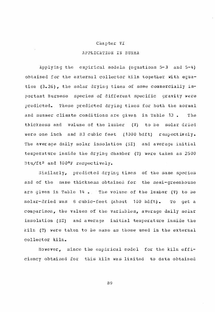
Apply.ing ·the empirical .models (e;3:u.atio11s 5-.3 and 5-4)
obtained .for the external collector ,Jdln together with equa-
tion (3.-26}, the so.lar dryiug ti.mes of so:me commercially im-
portant Burmese species of dif,ferent .speciof:ic gravity were
predicted. These predicted drying times for both the normal
and summe.r climatE~ conditions are given in Table 13 • The
thickness and volume of the luaber (V) to be solar dried
were one inch and 83 cubic feet {1000 bd£t) .respectiv,2ly.
The averagt.~ daily solar insolation (SI) a~d average initial
temper:at m:e inside the drying chamber {T) were taken as 2500
Btuj.ft2 and 100°F respectively,.
Si11.lilarly, pr-edicted drying times 0£ the same .species
and of t"he same thickness obtained fo:c: the semi-g.reenhouse
are given i:n Tabli;:~ 14 .•. · The volurie of the lumbe.r (V) to :be
solar-dried lilas 8 cubic-feet {about HW bdft},. To get a
comparison. the values of the variables, average daily solar
insolation (SI) and average .ini.tial ·temperature inside the
kiln {T) were taken to be same as thos~ used in the external
col.lector kiln,.
However, since the em:p.irical model for the kiln eff i-
ciency obtained for this kiln was limit.ad to data o.btained
89
90
TABLE 13
Pr:e11ictiri.g Drying Times for so.me Commercial Burmese \~oods using External Collector Kiln
Initial [1oisture Content 20-50 percent Final Moisture Content 8 percent
r I Sr. J Trade J B otanica.1 JNo.JName j Name J l i 1----· l I J J 1 jTeak }Tectona I j J gr an dis J 2 j2yinkadoJXylia I l j dola:i:hri for.mis I 3 ! Pauda uk j Pteroca rpus l J j macr-ocarpus j 4 I Thi tya j Shorea J l Aoblongifolia ! 5 J Ingyin fPa.ntacme I J tsiamens~s J 6 )In )Dipterocarpus J J JtuberculatQs J 7 ]Kanyin- JDipterocarpus ,) Jbyu Jalatus l 8 J Ka11yin- ,l Dipterocarpus 1 J ni l t.urbinatus J 9 jYernane ]Gmelina arborea J 10 J Sagawa i 3iche1ia cha-m,paca .111 i Hnaw 1 Adina cord if olia 112 i Binga J Hitrag-yna I j Jrotundifolia J 13 l'Thinga.n J .Hopea odorata 114 I Pyinma ! Largerstroe:mia j I J speciosa 115 ! Yon J Anogei.ssus ] J i accumina ta J16 jTaukkyanJTerminalia tomentosa 117 I Thinwin j Millettia _pend ula J18 JTaong- JSwintonia I ,tthayet .lfloribu.nda J 19 jTha.di jProtium seeratum J20 JThitkadoJCedrela toona
j G.:reen j I j j J j I I i I I I l l I j I j 1 I I I ] I J l i ! J I I I a 1 1 i
Sp.G£
0.:59
0,. 75
0 .. 86
0.78
o. 7 3
0.57
Q_,. L~2 0 .. 43 0.58 0,. 5.5
0,.64 0 .. 52
0.74
o .• 71 0,. 85
o .• 71 .o. 4-,
I Time I Time I I NormalJSummerj i (day} I (day) A j i I I l 5 j I i l I j J I .I 3 I l j j I ,I J I I J I I 1 I I i I I
1 I
10-181 :I
12-241 1
12-221 J
14-26 t I
12-24.1 J
11-22j I
10-18 i I
10-18 .I j
6-121 6-12j
10-181 8-16 j
a 11-20 J
8-161 j
12-221 I
1 l-22j 14-26 i 8-16}
I 11-22)
7-1:41
f j
5- 9j I
6-11 J I
6-1 OJ j
8--121 i
6-11,j l
5-10 J j
5- 9 J I
5- .9j j
J- 61 3- 61 5- 91 4- 8J
I 5- 9) 4·- 84
,i 6-101
I 5-101 8·-14j 4- 8 j
j 5-10J 4- 71
91
TllBLE 14
Predicting Drying Times £or Some Commercial Burmese Woods using Semi-greenhouse Kiln
Initial !oisture Content 20-30 perceQt Final Moisture Content 10 perceu-t
r , J Sr .• I Trade I Botanica.l I Gre:eu j Time I )No .. JName I Name t Sp.G.c.j Hormal J I i l I (day) I (day) J }---~-----+-----------,---+------+-----f i l I 1 I l :I 1 )Teak J T,ectona i 0.59 ;I 11-14 t I I I grand:is 1 ,I l l 2 tPyinkado I Xylia t 0,.7.8 :I 16-19 J I l I dolarbr:if or mis I I j I .3 JPaudauk I Pterocarpus .t O. 75 j 15-18 1 J l I macrocarpus I l J l 4 ,JThitya J Shorea l 0 .• 86 I 17-21 i 1 :J I oJ:JJ.ongifolia i I J I 5 Jingyin J Pantacrue I 0~78 1 16-19 J 1 I I sia.mensis I 1 l J 6 I In I Dipt.e.rocarpus I D .. 13 t 14-17 J ) J J tuberculatus J J l J 7 JKa.nyinbyu 1 Dipterocarpus j 0 .• 57 I '11-14 I t I ,I a.lat us I I J J 8 I Kanyi:n- I Dipterocarpus I O .• 60 1 11-1 ti i 1 Jni J turhinatus I i I l 9 I Ye1uane J G.melina ac borea ,} 0 .. 2 1 7- 'J J J 10 JSagawa j I'lichelia champaca I 0 .. 43 j 7- 9 j l 11 I Hnaw i Adina coardifolia 1 0,. 58 I 1 l-14 I J12 JBinga j Nitragyna I 0.55 j 11-13 I ,i J J rotund.ifoli.a l 1 j J 13 JThi.ngan I Hopea odora·ta j 0.64 j l.2-15 j 114 I Pyi nma I Largerstroemia. speciosa J D. 52 l 10-12 j )15 }Yon j Anoge.issus accum.iI1ata j 0,.74 I 15-18 I 116 jTaukkyan I Ter.minalia tom.entosa i 0,. 71 :1 33-16 I 117 IThinwin 1 r1illettia pendula 1 0.85 I 17-21 ,I 118 l'I'aung- I Swintonia flo-ri.buna.a I D.55 J 10-13 I J jthayet I 1 j J 119 jThadi l Prot..ium seeratum J 0.71 ) 13-16 j J20 1Thitka.do J Cedrela toona t o.rn J 9-11 J L---.l.
92
between 32.5 percent, initial moisture content and B.8 per-
cent final mois·ture content, the drying times g.i ven -were
predicted only b,etween 30 percent ini tia.1 d.nd 9 percent f i-
nal moisture content.
'fhe prt:H'l.icted drying times obtaiJ1,ed for hot.h ·types of
kilns indica,te th.at. the lumber with about 50 per-cent m.ois-
ture content can be dried within 6 to 26 days (table 13) ,
whereas the lumber initially at about 20 percent moisture
content can be dried below 10 percent moisture content with-
in 3 to 18 days (table 13 & 14).
Other wor.K in Bucma has shown that green .lumber two-
inch thickness and a.bout O .• 6 O green speci fie gravity can he
air-dried (under an open-shed}
tent within 7 veeks (Kyi,1981).
to 21 percent moisture con-
Therefo:r:e, solar drying
preceeded by air drying is ,Jui te favorable to dry the lnmher
bEi.lo:w 10 percent moisture content within one ~eek to three
For some locations which have heavy rain during the
four-,-mo.nth-rainy season ( .-p ,g . ·--• .... Rangoon) 1 solar drying can he ' used for eight months. Thus, for these places, air dryi.ng
under a shed can be started during the rainy season, espe-
cially for the re.fractory species,.
93
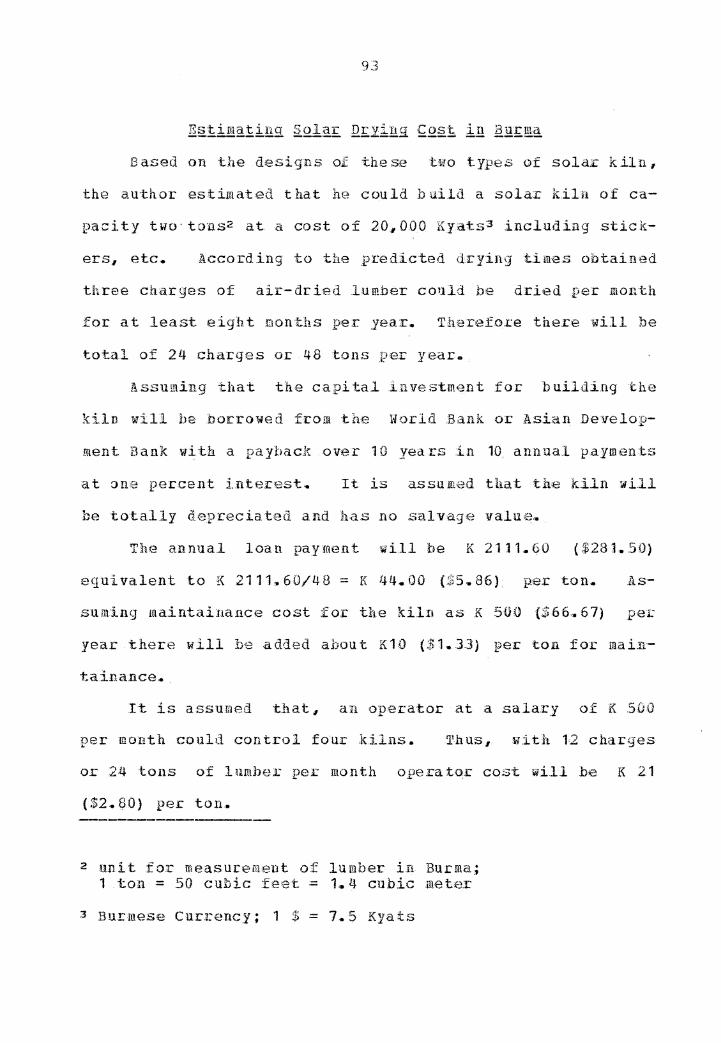
Estim.atinq Solar Drying_ &Q§.t iJ.! 12..i!:£!\El
Ba.sea on the designs of these ·two types of solar kiln,
the author estimated that he could build a solar kiln o.f ca-
p:aci ty two· tons2 at a cost of 2-0,000 Kyats3 including stick-
ers1 etc. According to the _predicted drying times ohtai.ned
three charges of air-dried lumber could be dried per 111011th
for at .least eight months per _yea:c. Th.erefo.r:e there will be
total of 24 chacges or 46 :tons _per y.ear.
Assu:rning that the capital investment for buildi.ng the
kiln will he borrowed from ·the World :Bank or Asian Develop-
ment Bank wiU1 a payback over 1 O yea rs :in 10_ annual payments
at one percent interest~ It is a.ssu JRt~d that tfoe kiln wi.11
be totally depreciated and has no salvage value,.
The annual loan payment will be K 2111.60 ($281.50)
equivalent to K 2111 .. 60/48 = K 44.00 {$5 .. 86). p.er ton.. As-
suJUing maintaina.nce cost for the kil.n as K 500 {$66 ... 67) per
year there will be added about K10 ($1.33) per ton for main-
taina.nce .•.
It is assumed that, an operator at a salary of K 500
per month could control four kilns. Thust with 12 charges
or 24 tons of lnmber per month operato,.r cost wi.11 be K 21
2 unit for measurement of lumber in Burma; 1 .ton = 50 cubic fee·t = 1. .. 4 cu.bic .meter
3 Burmese Currency; 1 $ = 7.5 Kyats
94
For loading and unloading the lum.ber, labor cost. is es-
timated to be K 10 ($1.33) per ton.
Electric power consumption :fo:c the .kiln will be at most
15 KWh r per day. The electric power rate in Burma is a.bout
K 0 .. 25 pee KW hr. Assuming an average dryi.i,1g time per charge
as 7 days, the po"Wer cost per- ton wil.l be 1/2 .x
{15x7) x0 .. 25=K13 {$1. 75). _
.Finally, the tota 1 cos·t to sqlar""'.".d.r_y one to.n o .f air--
The e mpirica.l model .for the overall e:fficiency of the
Iciln for the 21-sunny days only (EFFS) was,
EFPS = -~0794 + ~0206*µMC) -.Q00159*(IBC) 2
R-s~1uare= .. Q-6; alpha-Level=. {WO 1,;
101
Based on the results obtained for the semi-greenhouse
kil.n, it can be coricludad th.at;.
9/8 green yellow poplar lumbe.r can be so.lar
dried by a semi-greenhouse kiln to a moisture content belo\t
9 percent in less thau one month during the fall at
Bl~ ·, b · · ( 3· 5 09 I" o 1 0 P) ~r • -· ·· a.cKs urg., . N., o ,.,, , vi rg.1n.1.a .• With air drying it ~as
impossible to attain a final moisture content much belo14 15
percent.
2. _ The aver:-agf., overall efficiency o.f the kiln for 15 out
of 28 days of dr_y:ing f o.r which were o.bta.ined {a:ve.r-a~ge ,.in.i-
t.ial r,c, 32. 5-9 %} was 8 .• 3 per-cerlt .• The overall e:fficiency
of the kiln {E:PF) ~as significa:nt.ly related to the averag:e
initial moisture content of the lumber and daily solar iu.so-
lation. A practical empirical mod-Hl for the overall ·effi-
ciency was,
EFF = -.0767 + .Q0988*IBC
R-squa.re=. 98; alpha-leve.l=.tl01;
Final conclusions reached from: thi.s study are,
1. Solar d:cying times of difterent .lumber :species at
different locations .for both solar 'k.ilns can be predic·ted by
the following empirical equation.
102
where,
MCL= daily moisture content loss .in percent
EFP= tlie value obtained from the efficiency model
SI= daily solar insolation in Btu/ft2
ACY= .area of the collector-cm1er in f t 2
:R = ratio of total solar energy incident on the collec-
tor cover to the to·tal energy available to the syste.m
V = green volume of lumber in £t3
SG - green specific gravity
:i'i - average Lnitia.l temperat-u:cr~ insid.e the drying ch.amber
in °F
2. _. A comparison of the actual drying curve observed. i:n the
second run of the external collector kiln showed good agree·-
ment with the predicted drying curv,e obtained from the empi-
raica1 equ.at.ion.
J.. Based on this study it is believed that. solar tlr_ying of
lumher preceded by air d.ryin.g will .be su.ita.bl-e for condi-
tions in Burma, in order to attaln a £inal moisture content
be.low 10 peccent vithin one to thrf'..!e weeks ..
LITERATU.RE CITED
American Society of Heating and Air-conditioning Engineers. 1958. Beating 1 Ventilating and Air Conditioning Guide. 36th Edition. American Society of Heating and Ai.r Conditioning Guide, Inc •. 62 ~orth st. New York 13* NY. 503 pp ..
Anonymous, 1980 •. One ray of sunshine~- the energy crisis. lJo.rthe.rn Logger and Timber Processo,r,, March,, 198:0 •. pp 24-25 ...
Banks, c •. H. . 1969.. . Solar dr_ying of tim;ber - a development study. CSIH Sub·ject. SRcvey O/Hou t l0., i?.:cetoria, .South A .. frica, June, 1969.. 27 pp. (Un_publishedJ ..
Bois, P.J. 1977. Constructing and op~:c:ating a smal.l solar-heated 1.umber dcyer. u. $ .. _p .• .lL, Fore.s:t Service, Forest Products Ut.iliza tion Technical He port No .. 7... January, 1977. . 4 pp ...
.Brace Research Institute. 1975 •. · A surv,ey of so.la.r ag:cicul ture dryers, •. · Technical Report T99.. Decem.be.r,, 1975. r1cG.i11 University .Fae ulty o.f Engineeri11g.. Brace Besea.cch InstitutH, 1'1ontr-ealJ Quebec, Canada ..
Casin., R • .F. 11 E. B .. Ordinario, a.nd K. Tamayo. 1969 ... · S9lar drying of apitong. 11arra, .red .lauan, and tangi.le. The Philippine Lumberma.n 15(4) :23-JO...
Casin, R._F., P .• __ .v .. Bawagan .. 1978,.. Solar drying -of .lumber in the Philippines •. _ Proceedings o.f the solar d.rying workshop.. . !'la.nila, Philippines.. October 18-2·1, 1978,. Organized .by ·the ministry 0£ energy ..
Choong, E. _T., and D ... M. Wetzel. 1981.. Feasibility of utilizing solar and forest biomass energy .for dry.ing Mood in Louisiana. .Re.search proposal submit·ted to Division o:f Research and Develop.me.nt, D~partment of Natural Resources, state of Louisiana. f'ehruary;, 1981.. 10 pp. (Unpublished)
103
104
--------------. 19Kl. Feasibility of u·tili:zing solar and forest. biomass energy for: drying wood, in Louisiana .. Prepared for Department of Nat.u.ral Hesom:ces 1 state of Louisiana. January, 1983.. 87 pp.. (Unpublished)
Chu.ndo.ff, M., E. D .. Maldonado, and .E •. Goytia. 1966 •. , Solar drying of tropical hardwoods,. .For. Se.rvice .Research Paper ITF-2.. April,, 1966. 26 pp.
Cooper, G .. A. 1966 •. Utilizing of solar- energy for drying of wood.. North Central Fo:rest E:xperiment Station, Ca.rbondale, Illinois,. June, 1966,. _ 8 pp... (U}i.puhlished) ..
Davidson, R. w.. 1980 .•. Se.rvice Re.l_:)Ort :for esta.blislun.ent of the Forest Research Institute at Burma.. JS pp. (Unpublished) •. ·
Denig •. J, and E~ M. Wengert. 1982. Estimating air-drying moisture co.ntent losses for red oak and yellow pop.lar lumber. Por. Prod. J. 32{2):26-31.
Dohn, G,. . D. .. 1963,. . D,egrade in so.lctr ilcying o.f mahogany (Sweetenia marcophyl1a, King).. Repo.:rt submitted in partial fullfilment of the .requireme~ts fo.r credict in Ge.nera.l .Forestry 191, Problems in wo:i:Ld .Forestcy, Rio Piedras, Puerto Rico. August, 1963. 21 pp. { Unpublished) ..
Duffie., J.,. A • ., and w. A •.. Heckman... 1974.. Solar energy thermal processes. A r«iley-Inte;1::scie:nce publication. John Wiley & Sous, New York., N. Y.. 386' pp ....
Duffie, N. A., and D. J. Close.. 1978. The optimisation of a solar . timber drier using an adsm:hent energy store. Solar Energy, Vol. 20: 405-411
Forest Dept., Burma.. 1979,. .· Report submited to the .Hinistry of Agriculture &, Forests. 211 pp.
Garg, a. !?. , 1974 .. , :E.f.fect of dirt on transpare.n·t covers in flat-plate solar energy col.lec·tors. Solar E:~ergy, Vol .. 15:299-302 •.
Gough, D. , K .. " 1977.,. The design and ope;ration <>.f a so.la:c timber kiln,. Dist..rihuted by the .D~p.artm,ent of Fo:xestry, Suva. No. ,67" 1977. pp 17.
105
Guo, X. z., 1981. Drying lumber with sola.r energy .. Industry o-f Forest:cy .Products (Linch.an Go.ngye)'". No,. l, 7-8 (Ch,,:q Timber Company of Fuyang Prefecture, Anhui, China. (Cited in Po.rest. Products Abstract No. 1230, June, 1983 •.
Kumar, s .... 1981 .... · Utilization of solar en,ergy in India. For. Prod. J. 31 (9): 10-12.
Kyi, w,. 198 l. Preliminary Studies: on the ai:c-seaso.uing behaviour o.f leza { Laqe:i;:stro-em;i&!: tontentosa ) .. F'c • .R. I .. Leaflet No. 6, Forest .ResHarch. Institute, .Yezin, Burma .. February, 1981. pp 7~
------... 198 l. . Investigation ~n the physical and mechanical properties 0£ thadi and tinyu,. . if.; R. L. Leafl.et Mo,. 10, Forest Research Institute, Yeziµ, Burma~ February, 1981. pp 10. .
Lee, J. F,. , and F .. w. S,ears. , 196,3. Thermodynam·ics, Seco.nd Ed .... Addison - Wesley Publ .• Co,., .Palo .Alto.
Luik.ov, 11 ... v. 1966,. .. Heat and r1ass Tra1is.f,er in Capillary-porous Bodies.. PHrgamon Press, Ne'W Y,ork ...
Lumley, T ... G., and E,. , T .. Choong. 1978 •.. use of sola.r e.nergy to dry southern bottom.land ha:rdwoods. Paper presented at Session 33,, drying and storage, 0£ the 3.2:nd Annual i1eeting of the Forest Products Research soc.ie·ty • June 29, 1978, Atlanta, Georgia.. 10 pp •.
Maldonado, E., and E. Peck. radiation in Puerto Rico.
1962. Drying by solar For. Prod •. J._ 12(10):487-488.
Nartawijaya, A,., K,. Kadir, and K. Sali)d. 1976 ... Solar drying o.f jeungjig { Alhi,sia, !a.lcat$ Back,.) and rubber wood { ,!!~Ye!! brasilie.nsis Muell ... Arg,.) .. Forest Products Research .Institute, Bogor-Indone.sia, .January, 1976.. 11 pp ..
Martinka, E. 1969.. Predrying of some ,G.hanain timhe.rs. Forest .Products Research I:nst:itn,te (Kumasi, Ghana). Technical Note No,. 1 L •. September, 1969.. 8 pp ..
106
L'.Ic,. Comick, P ... o .. , 1980.. Sol.ar heating system for kiln drying lumber •.. su:nworld., 4 (6) ., 198{'1: 204-20 . .6.
:Na th,, P .. , a:ud B •. L. Bali •. ·· 19 ., A process for the small sawmiller and timber-based industry.. Wood Seas01ling B~anch, P •. R. I., Dehra Dun, India. 10 pp ...
Oliveira, .r .... c •. s •. 1978,. . Solar drying of green oak {Quercus spp.) lumber.,.. Unpublished M.$ .. thesis •.. · VPI &. SU, Blacks.burg, Virginia .•. · 61 pp .•.
Oliveira, L •. · c., s .. , c •. Skaar, and .E •.. fi .... Weng,ert. 1982. Solar and air lumbe:r drying during -winter il\: Virginia .. For. Prod. J. 32(1):37-44.
Panshin. lt,.. J •. and c •. deZeeuw. 1970 ... Technology., McGcaw-Hill, New York ..
Textbook of :wood 705' pp,.
Peck., E. c.. 1962 a. Drying 4/4 red oak by so.lar h.ea·t. For. Prod. J .•. 12 (3): 103-107 ..
• .. 1962 b ... Drying lumber by solar ene,rgy .. Third Quarter., 1962,.
Sun at
~Plumtre, R •. A ... · 1967. The design and operatio:g. 0£ a sma.11 solar seasoning };:iln on the equator in Uganda ... · Co:ramonw,. For. Rev., 46(4):298-309.
-------------.. 1973,. . Solar kilns: Their suitability .for developing countries._ ON Ind. Dev •. Organ., ID/WG •. 151/4 •. 38 PP•
Ramos,, J,. B. F,., et §..1 1981. study on methods of drying the .a.mozonian timbers.. Center of wood Tech.nology, .Bel-e,m/PA-Brazil, 1981 •. 5pp.
Read, w. B., A •. Choda, and P,. I,. Cooper. 1974. A solar lu.mhec kiln. . Sol .•. Energy, 15 ( 4).: 309·-316.
Rehman, M. A. and o .. .P .•. Chawla. . 196 l. Seasoning of timber using solar energy:.. . Indian .Forestry Bullen.tin No .. 229 {New Series).. 13 pp ..
Rodger, .A.. . 196.3.. A Handbook of the .For,est Products of Bu.rma.. Superintendent, Government Printing & Stationary, Rangoon •. 149 pp.
107
Rosen1 H. N., and P •. Y. s. Chen. 1980. Drying lumber in a kiln.with ·external solar collectocs. American .Instituta of Chemical Engineers. No ... 200, Vol .. 76:82'.-'89,.
Ryley, T.. 1980 •.. Solar timber kilri. .Australian For. Indus. J. ~1980. pp 25-26.
Schneidec, A., F .•. Engelhardt, and L •. Hange;c. · 1979,. Vergleichende untersuchungen ube.r di~ freilufttrocknung und solartrocknung von schnittholz lll\ter mitteleuropaischen wetterverhaltnissen. Ho.lz/als Roh und Werkstoff 37(1979):427-433 •.
Sha:cma, S. N .. , .P .. Nath, and B. L. Bali... 1972.. A solar timber seasoning kiln .... · J ... Timber Devel. Ass.oc ... Lndia. 18 { 2) : 2 8- 3 L,
Sharma, s,.. M.,.. P .. Nanth, and s .. P ... Bandoni. 1979 .. Commercial T:cials on a 7 .. 1 cu. M,. solar kiln. India:i;i For, • .Bull, •. No •. 274 1 Forest Research Institute and Colleges, Dehra Dun, India.
Sharma, s. N. . 19 80. . Feasibility o:f solar tLmber drying in tropical locations.. Paper presented at the IU.F:RO Division V Conference ... Oxford, England, April, 1980.
Shelton, J. . 1975. .. Underground .sto,:cage of hea·t in solar heating systems .•. Sol,. Energy Vol. 17, pp 137-1'.43 ••. ·
Slterwood, G .• E. 1979.. Perfo:r:mance of wood in a do-it-yourself solar collector.. For. Prod ... Lab •. , Res •. Note FPL-0204, 1979.
Shottafer, J ... E., and c. E .. Shuler ... 1974. Estimating heat consumption .in kiln drying lumber •. Life science and Agriculture Experiment Station .•. 'l'ecb.nical .Bull .. 73, Sep·tember, 197f.J,. .· 25 pp .•
Siau, J .. , F. 1971.. Flow in Wood. ... Syracus,e University Press •. Syracuse, N •. Y. 131 pp.
Simpson., w. T. 1977... Solar lu.mber designs for devel:oping countries,. Proc. Practical Application of Solar .EuergJ to Wood ProcE~ss.ing ... Blacksburg, VA,. January 6-7, 197'7. Published by For.. Prod ... Res,. Society., .Madison, llL. PP• . 56-61.
-------------•. 1981.. Tcip :cepq,rt travel ·to Sri Lanka :from February 1, 1981 to February 14, 1981. 3 pp. (Unpublished) .•
108
Simpson~ w. T • ., and J •. L. Tschernitz. dry kilo gets trial in Sri Lanka. February.,, 1982. pp ... 13 .•
198 2. Low---cost solar World Woqd .J,,.
Simpson, !& .. T. 198.2. Trip report on FPI. sola:c kiln activities in Sri Lanka and Burma ... October,. 1982 •. 1 pp ... ( Unpublished} •
-------------.. 1982.. Insta.latiou of solar .kiln at the Forest Research Institu,te at Ye.zin., Burma,. . .Service Report. . 97 pp.. (Unpublisltecl) ..
Singh., Y •. 1976.. .s·tudies on a .solar timber seasoning kiln .. '!PI.RI Journal, 6 (1}" 1976. pp i.n-4.4 •.
Singh, Y ... , and A •. Chandra... 1978. Design of a so.lar timber seasoning kiln. Paper presented at :1n·te.rnational Solar Energy Cougress., Jan. 16-21, 1978., New Dehli, India .•
Skaar,, c,. . 1972,. . Syracuse N. Y .•
water in Wood,. 218 pp._
Syracuse Uni ver.s.ity Press .•
--------- .. J977 •. Energy requirements fo:c drying .luilber,. Proc •. · Practical Application. of So.lar Ene.rgy to Wood Processing. Blactsburg 1 VA •. January 6-7, 1977. Published by ·For .. Prod.. Res. so.ciet:y, Madison, WI. pp .•. 29-32 ..
Stein.mann, D. E • ., H .. p. Vermaas,., and J .. B •. For.rec,. . 198D,.. So lac timber drying Jt.ilns: Part 1: Review 0£ previou,s systems a.nd control rneasui::es a1td descriptio,!l of an automated solar kiln.~ J •. Inst. Wood Scienc~. 48. pp. 254-257 ..
------------ --. 1981. Solar timber drying kilns:Part 2: iv! icroproces.ser control of a solar .k i:Ln .•. · .a,. Inst. :woo a Science.. 49. pp ... · 27-31,.
Tao, Y .. , a.nd c. Hsiao.. 1964.. Lumber solar drying at Taichung-.. Bull, •. No,. 63-N-490/C, Natl .... · Chung Hsiug Univ .• , Taichung, Taiwan.
Taylor, .P ... w.. 198 2.. A compa;c:ison of enecgy .ro1a,;ruirements for kiln-drying southern pLne at different drying temperatures. Wood and Fiber.Sc., 14(4). 1982. pp 246-253 ..
Troxell, H. E., and L. A. Muller •. 1968. Solar lumber drying in the central Rocky Mountai~ region .... For .. .P.rod. J.. 18 { 1) : 19-2 4 ,.
Tscherni·tz, J. L., and w •. T .. Silllpson. 1977. Feasihility of utilizing sqlar energy .for in developing countries,. u.s .. D .. {\ .. Fo_rest Prod •. Lab .. , Madisop, HI~ January, 1g11.
Solar kilns: drying lu:iabe.c Service, :For ..
63 pp.
--------------... 1979,.. Solac-heat.ed., forced-air, lumber drye:r fo.r tropical latitudes •. · Sol. Energy YoL •. 22, pp. 563-566 ..
Tschernitz, J,. L.. 1981. Ins·tructions for o,peration of FPL solar kiln,/Sri .La.nka (Horana) •. U .. $ .. D..:A. Forest Service, Por. Prod._Lab., Madison, WI. February, 1981. 10 pp.
----------------. 1982.. .. Operation of FPL £orced air solar dryer, Forest Research Institute, Yezin, Burma.. u.s .. p • .1t. • . Forest Service, Poe. Prod. Lab .. , Had.iso11, PU. Aug·u.st, 198.2,.
USDA Forest Service. 1974,. iood hand.hook--wood as an engineering Jnateria.L, . US.DA Agric .• Ha.ndbk •.. No .•. 72 •. · u. s •. · Govt •. Print .•. O:f:f., WAshington, DC.
Vick, c.., B. 1977.. A solar air-heater as a supp.lemental heat source in lumber force!l-a.i.c dryer. 4710 • .FS-SE-3501-6 (6.5) .•.. Final study repqrt •.. Athens,. Gt:orgia. November, 1977,. . (Unpublished) •. ·
Vital, B .. .. R.. 1976 •. · Uti.lization of solar en,e~rgy for: seasoning wood. Re vista Ceres 23 {l.25): 1-10, l976.. 10 pp.
ffeast, R •.. c.. 1967.. Handbook of Chemistry and .Physics. 48th edition, 1967-68.. The chemical rubber co ... , 18901 cramrnod .Parkway, c leveland, Ohio, 44128,.
Weik, B,. .· R,. Practical drying techni;1ues for yellqw:-poplar S-D-R flitches .•. 1982. Unpublished rl.S. Thesis .• Virginia Polytechnic Institute & State Univec.sity, Blacksburg, VJL. 63 pp .•
Wengert, E. M •. · 1967.. Ene:r-gy losses fro •. m a solar dryer,. Unpublished M. s .. thesis.. Colorado State University 1 .Fort Collins, CO. 6Q pp.
110
-------------. 197 l. Improvements in soJ.ar dry kiln cles.ig.q,. . u. s .. D .. A .• Forest Ser.vice, .For.. Prod •. La.b.., Madison, WI. Research Note FPi.-0212,, 1971... 10 pp .•
------------- .•. 1974,. How to reduce energy consumptim,1 :i,,n kiln-drying lmnber. u.:s.D.l,l,. ~'orest Servic~, For'9 Prod. Lab., L'ladiso.n, WI.. Resea:rc;h .Note FPL-0228, 1974.. 4 pp.
·-------------, •.. · 1960. Solar heated. lumber dryer for the small business. Virginia Coopei:-a ti ve Extension Service. VPI & SU, .Blacksburg, VA,.., April, 1980. 16 pp ..
Whaley, s. n~ 1981 .. Solar kiln drying .. ----------------·------- ·--· . - pp.. 28' · .29.
Yang, K. c. 1980.. Solar k.iln performa:rice at high latitude, t+8°N.,. . For ... ]?rod. J •. 30 (3) ::pp,. 37-40
Youngs, R. L... 1959.... Recomme11da tiq.ns of. the Madison confE?rence 011 fundamental res•earch in wood drying·.. For •. · Prod. J. 9{~ :121-124.
Zimmerman, o~ T.# and I. Lavine. 1945. Industrial Reseacch Se.rvice•s Psychrometic Table,s and Charts ... · Dover, N ... H., Industrial research service, 1945 •. · 162 .P.P•
Append..i:x A
·poffEST A.REA AWD .FOREST INDJJSTftIES OF HIJRH.A, MALAY SI.A, .AHD PHILIPP TN.ES
Item Burma EiaLaysia
I ] J jForest Acea (acres) j96,000,000f 20,0.00,001) J I l J Reserve Forest (acres) j 24,000,000 j 14,000 ,00,0 i I J jLog Production 1 5,600,-000j.231.,IWO,OOO ! (cubic .ft) (1970) I j J I J )Lumber P:roduction ]21.,tHHl,OOOj 82,0,,00,000 I (cubic :ft) ( 1970) I .I I I i JPlywood Production l 380,0901 8.,000~00-0 l (cubic ft,) ( 1970) I I I I I
I Phili.ppi:nes I
l :1 31,00:0,000 l j 23,500,000 ,t j388,000,000 i j I IJ7., 700,000 j ,I I 20 ,.000,000 J ]
] J j I j I j j I i j I I
J No. of Saw.mills J 207 (1979) I J J l j No'"' of Plywood I1il1s I 3 ( 19.7:9} 1
650(1979) J 1
37(1979) I
1 325(1976) J
J 33{1976) l
j 100 {1.976) I
I 15 { 1976) J
j j
1 i l J No. of :pry Kilns i 20,{ 1979) I 1 J J I No. of P rese.rvation I 1 { 1979) I J Plants l J J l l
sl 82(1979) j
I I I I ___________ __.. _____ ;;,__. ______ -'-----~
Adopted from Davidson (1980).
]l 1
Appenclix B
Tnrn1rn EXPOH'r OF BU.Ht!IA .FO.R ~"'ISCAL YEA.R 1977-78,
i j HOPJ?US ton) Cubic Meter j Value I Source I /ton * 4 I (.Kyats i.p l j 1 j l T housaitds) j
J 1 j t t l j I jTeak log I 45,266 ) ·s 1,479 :I 233,722 I J j l JHardwood log j 9,630 .I 17, .J3lJ J 7,272 I l J j jTeak Conv,ersio.n j 38,653 1 5'.c4, 114 I 160,918 J J l i i:Hardwood Conversion 1 171 I 239 ,I 205 3 1 ! J JPlywood, Veneec., I j j j I i i J ?losaic, Par,{ue·t & etc I j 1 7.95 J I I J JTotal J 93,720, I 153~ l66 ;) 402,912
* Hoppus ton - unit for measurement of log in Burma = 63. 7 cubic feset : 1. 8 cubic meter
ton - unit for measurement of convta:rsion - 50 cubic feet = t. 4 cubic meter
+ Kya t - Burm,ese Currency; 1 :ji = 7 .. 5 Kyats
Adopted from the Repor·t {1980} o.:f forest Department to
the Mlnistcy of Agricultui:e and Forest, Burma.
112
., a I ,j J I I J I I j I j j I 1
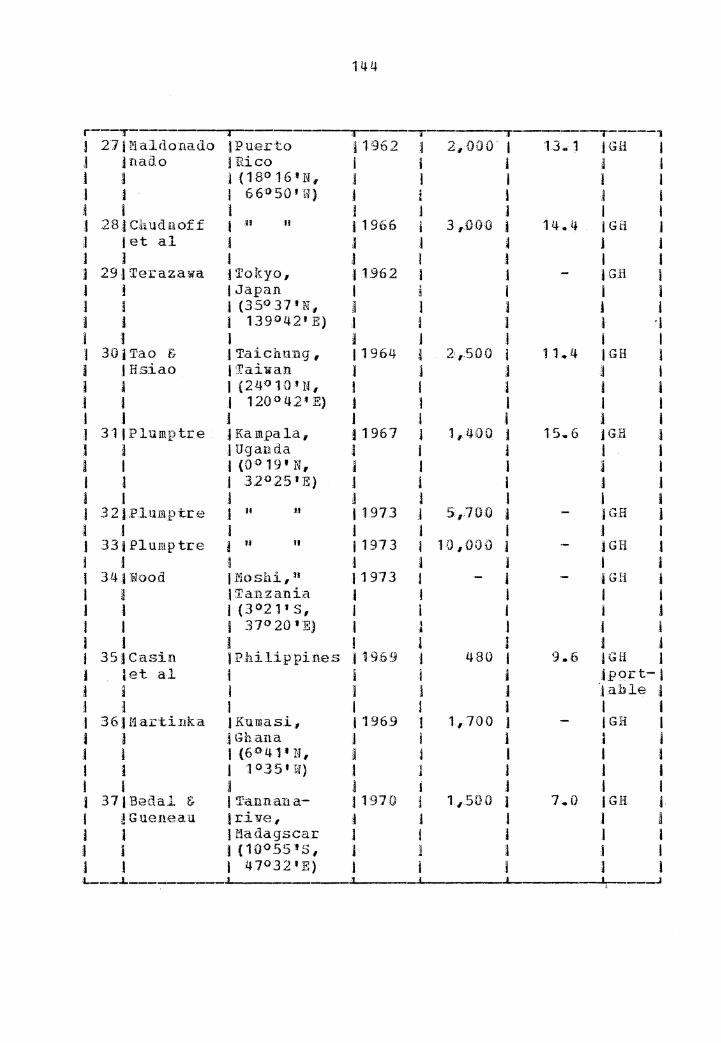
REVIEW OP SOLAR LUMBER KILNS
C. 1 !J.li.l::£.ED STATES Qf AfilERICA
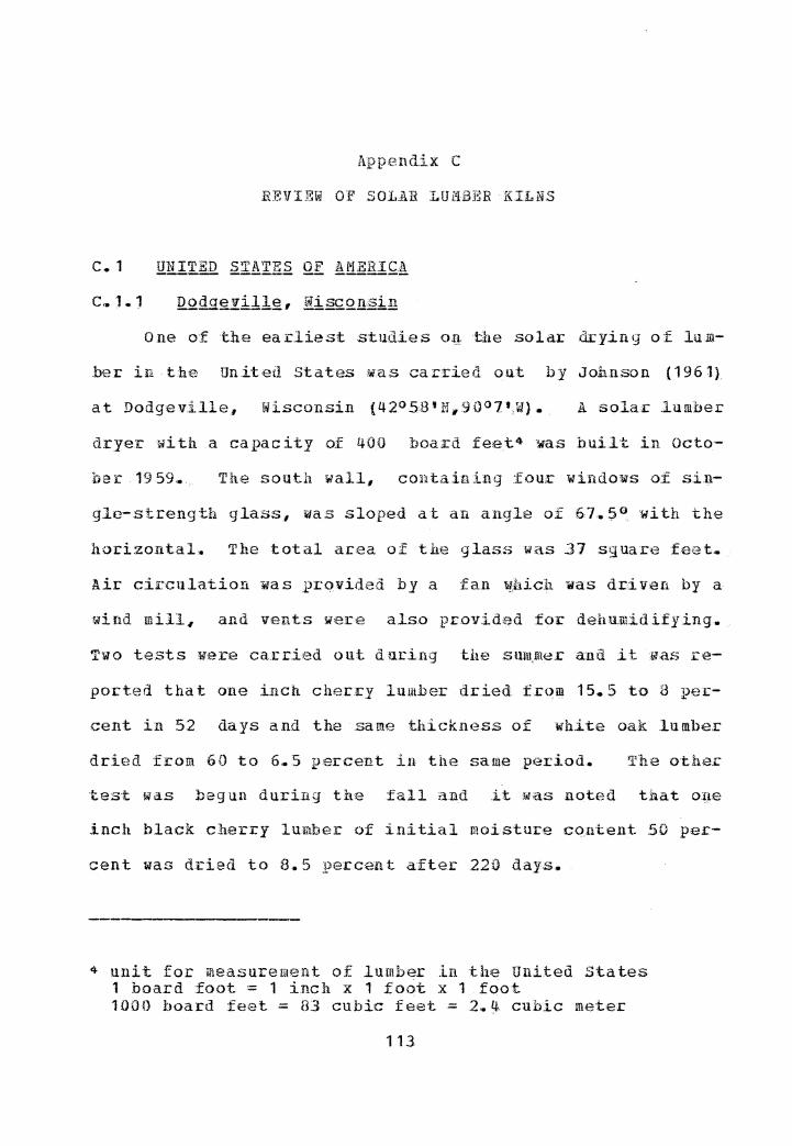
C.-.. 1.1 Dofulg!il!g, Wisconsin
One of the earliest studies on the solar: drying o-f lum-
ber in the United States w.as carried out by Johnson (1961}
at Dodgeville, Wisconsin {42°5B'N,90°7',W). A solar .lumber
dryer with a capacity o.f 400 board feet4 was built in Octo-
her- 1959,. The south wall, containing :four windoMs of si.n-
gle-streng-!::h glass, was sloped at an angLe of 67. 5° with the
horizontal. The total area of the glass W<i.s .37 sguar,e f-eet.
Air circula.tion was prqvided by a fan W;hicll ~as driven by a
wind mill, and vents were also prov:i.d?d fol:" dehmuidify ing.
Two tests were car-ried out duri.ng the smu.me.r a:ud it was re-
ported that one inch cherry lumber dried from 15.5 to 8 per-
cent in 52 days and the same thickness of white oak: lumber
dried from 60 to 6 ... 5 percent in the same period .• 'l'he other
test was begun during the fall and it was noted that one
inch black cherry lmrtber of in.itial moisture content 50 per-
cent was dried to 8.5 percent after 220 day.s.
4 unit for measurement of lumber ln the United States 1 board foot= 1 inch x 1 foot x 1 foot 1000 board feet= 83 cubic feet= 2.~ cubic meter
113
114
Madison. Wisconsin
In 1961, Peck ( 196 2 a,) d;esigne<l and tested a solar
dryer at Hadison, Wisconsin {4.J/.>5-'N, 890.23 1 W). _ The r:oof and
all Ji.falls except thu north wall, which was sheathed :with
plywood, we;r:-e coverf:1d with. two layers of tra:nsparent plas-
tic._ The size of the dryer .was 7 .• 5x l2. 7x8 fe.et with a ca-
pacity of 425 hoard feet. :rlu:ee charges o.f green ope-inch
red oak lumber were dried to 20 percent moisture content ..
He reported that this required 33 days during Hay and June,
23 days during Augus-t. and September, and 105 days :fcoiil No-
vember through Harch. Peck also noted that the temperature
inside the d.ryer was a.l;;.ra ys higher, and the relative humidi-
ty inside the dryer was genera.lly lower than -ambient condi-/
tions. He concluded that the so.la.r drying time to a mois-
ture content 20 percent can be ceduced to about one-hal.f
that req:uired ·to ai:r d.i:-y the same lumber.
c .• l.3 Sauk £itY., Wisconsin
'.l'wo other solar gr2enhouse type dry-fH,s, designed by
Peck ( 1962 b) , were cons·t.ructed at a small sawmill in Sauk
Wisconsin. 'IU1e capacity o.f each
dryec was about 2,500 .board feet and ain circulation in each
kiln was provided by two 18-inch £aas •. The dcyers were
identical except that th.e fan.s in one dryer were powered b_y
115
1/3 HP electric motors ~,herea.s in the other they were driven
by a wind mill.
Fort Collins Colorado , --- __ , _____ I --------
In 1962, a greenhouse solar drye.r with a capacity of
1500 board £eet was co:nstrur;ted at the Colorado state Univ-
ersity, Fort Collins, (40°36'N .. 105°4 1 W) .. The dryer wa.s 18
:feet long froill east to west, and 10 fe;et Yide fr:om north. to
south .• , A.11 walls except the north wall were covered with
translucent fi.bf:~rglass (li!here:as the r:oof :and the no.cth wall
were covered with fiberglass~ The roof was tilted at an an-
gle of 17° to the horizontal, facing south. Troxell and
Mueller ( 1968} tested seven charges of one-inch Engelmann
.spruce and lodgepole pine lumber at diffen:'!nt seasons. .Each
charge consisted of an e gua.l mixture of both species
,. According to tht..~ir report 1 it rf,iguired only 5 to 13 days to
dry the lumber to 1.2 percent moisture conten-t du.cing summer
and fall 1 and 13 to 25 days during the winter~
c.1.s In 1977, Wengert designed a.nd constructed two semi-
greenhouse type solar kilns at Virgi,nia Polytechnic Insti-
tute and State University, Blackshurg(35°9'N• 81°0 1 W). The
first ki.ln had a capacity o.f 150 to 200 board feet with a
116
maximum board length of 4 feet •. The flo.or: and the wall.s ex-
cept the south :wa.11 were well insulated... The roof Yhich :was
tilted at 45° '.to the horizontal , and the south £acing wall,
'ffere covered with two layers of t:cauluc~ut weather re.sista:q.t
polyester film two inches apart.
Oliveira, Skaar and Ren.gert (1982) tested a mixture of
one .inch thick red oak and white oak lumber during the win-
ter o.f 1978 .. They found t.hat th,e lumber reached 20 a:nd 6
_percen-t: Rloisture co:nteut in 80 days a:nd 125 days respectiv·e-
ly.. The average They also air dried a pile o.f end-matched
samples during the same timB :p.eriod,. This lumber reached 20,.
percent mois·ture con tent in 105 days a~ii 14 ;percent in 162
days.
A description of tile qt.her k:iln which was conducted in
this study is given later u.nd.e:r pro,ced ure.
The third solar .kiln d,e.signed and co11structed at
B.ladcsbm:g in 1979 had a capac.i ty of 1500 boa:c-d :feet,. The
roof consistail of a double lay~r
ped at a 45° angle facing sout4.
of cl,ear .Plastic and slop-
It ·w1as 17. 6 fee·t long £rom
east to west, 6,. 2 feet wide from south to n9rth .. The south
:wall was 3.1} f ee·t high a 11d the no:rth wall was 9. 5 feet high
The walls and floor ·wece insula:ted with 4-inch-thick fi-. '
berglass faced with 1/4 inch plywood inside and out.
117
One inch thict black walnut 1uIDber were dried during
the period from t'e.brua.ry, 19 80 th i:-ou.gh April,, 1981 •. · Afb~r
69 days of clryi.ng, it reached 8 perce11t moisture coutent ..
The. initial moistuce content was repq.r:t.ed to be 71 .. l;i per-
cent.
c. 1.(:i
A small sola".1: heated lumber drye;r 1dlich was .basically
th.a same design as the dryer of Joh.n.so:a (1961) was described
by Bois (1979).. Johnso.n constructed and tested this dryer
with greater holding capacity of 750 board .feet and oth~.r
i.mprovements •. The south wall which was ti.lted at 50° to the
horizontal consisted of four storm glass windows .with a to-
tai g.lass area o:f a.bout 47 sguare f,e-et.·
c. J. 7 Magj._:~Q!!, Wisconsin , .E.xternaJ:-c:ol.lec-tor IX.Bti
Tschernitz and Simpson ( 1977) p:ropo,sed two.. types o.f .so-
lar .lumber dry .kilns, one a greenho,use type and the other- an
external-co.llectoc type They teste.d the feasibility of
using solar energy to j_mprove lumber drying by small-to-med-
ium-scale operators in developing countries ...
.Based on the .feasibilit..y study, tb;e.y designed and ·test-
ed a prototype solar dryer of l, 000, board feet caf?acity, at
the Forest. 21.·oducts Laboratory, in Madi.son i:n 1978. The
118
collector :was e.xterna 1 to the drying chamber and ·was hori-
zon taL. . It was designed to be locat~d at t.he Republic of
the Philippines, located at 14°N latj_tude. Thus horizontal
orientation was considered to be satisfactory in order to.
take advantage of the low expense of building t.he collector
in the ground,. ..
The description of this sola.r kiln., which was used in
the main portion of this stud.Y# is given in the pro,cedure.
Ba ton .Rouge , Louisiana
Lume:1.y and Choong (1978) designed a.nd tested an experi-
mental solar kiln of 360 board feet capac:i ty at the Louisia-
na State University, Baton Rouge (30°281 N# .9l 0 l0 1 W}., in 19T7
• The kiln was first designed and operarted with a horizoQ.-
tal fl.at·-plate collector but was later, modified by r~plac-
ing the flat-plate collector with a tb,ree d:imensional box-
·type collector,. The collector area was 26 .. 25 squa.re .feet
inclined at a 49° pitch to the south.. six bottom.land hard-
wood species ·were tested, :starting frQm April, 1977 and it
was re.ported tltat elm, sweetgum, hackbe.r.ry and sycamore
which were dried during the sutllmer to a final mois·ture cou-
tent of 15 peccent in 10 to 17 days, wl~ereas ash, hackberrJ
and .. red oak which were dried a. uring t}i,e spriilg required 18
to 27 days to reach 15 p,ercent moisture. content .. They al.so
119
· concluded that solar-dr_yi.ng rates :were two to three times
faster than ai.r-drying,.
C .. l. 9 Carbondale, Illinois
.An experimental-scale exterr,tal collector type solar
kiln of capacity 500 boardf'-eet :was designed aud tested by
Rosen and C.hen { 198()) a-t; the North Central .Forest .Experimen-
tal Stat.ion, USDA Po.rest Service, Carbondale {37°4.2 1 1'1,
89°12 1 W), Illinois.
Tile co.llector was t.il ted at 37. 5° to the a!1orizonta.l and
the collector plate was built from the aluminium beer cans.
The d:rying chamber was about 8x8x6 .• 5 :f~:et in dime.nsions, and
they were inexpe.nsi ,,e, required low-le.vel opera t-
iug skills and obtained .high g:uality dried--lumber,.
All these kilns were designed and tested by Plumptre
who started the solar lumber drying in Uganda.
INDONESI.A
f'lartaidjaya g_:t, al (1976) designed and tested a green-
house type solar .lumber dryer at Bogar {6°45 1 s, 106°45 1 l•
The roo£ and the -wal.ls -were covered iWLth. transparent plastic
sheet.. The dimensions of the dryer were .6.9 .feet long, 5.4
feet wide and 6,. 4 feet hi9h. _. Jeungj iri,g species ( AJ.hi.1:ia
@J&s!.1~ } of 1-inch thickness .and l,. 5 inch thick rubbe.c wood
{ Jig_yg2;_ hca.siliensis ) were dried .. It was concluded that
solar drying was always faster than th,e air dr1•ing foJ:: .both
S,Pecies.
c ... J5 f..LLI A solar dryer ·with a capacity of 2,100 board feet was
constructed and operated in P:iji (18'l50 1.,S, 175.0.E} by Gough
(1977}. Several .Fiji timhec species we.i:e tested and the re-
sults obtained we:re considered to be satisfactory,. r·t was
·noted that 1-inch kavuea { .Endos11ermu.m ~'a.£:£QEl!Ji.:llJ!.!!1 ) , which.
134
was taken directly from pressure t.reat-me1lt with water-borne
pr.-eser va ti ve salts, dried frmn 115 to 16 _percent moisture
content in 30 days. The te,st. was carried out d1.1.1:ing April
which is a very we,t month for the location,. Another ·test on
t.he same thickness and the same species was also co.nducte.d
during March requ.ired 31 days to dry the lu-mber .from. 85 to
14.7 percent moisture content.
was dried, during October and November, and the lumber were
dried -to 15 .. 5 moistu.re content in 2:3 days from an average
initial moisture con'tent of 47 .. 5 perce:n_t. Drying1 during
hot dry veath.er in February, with 1-inc.h ai.c-dried .mahogany
( 2.Rietenia macr:oph.ylla } from an initial mois·ture co.utent
39 percent,
days.
to 17. 3 ;percent moisture content took only 7
This kiln -was of the greenhouse ·type with a capacity of
2~100 board feet.
c .. 16
Schneider gJ;;. al ( 1979) designed and. te.s:ted a g:ceenhou.se
.28 miles
from riuuich,. .· The dryer had a capacity of a:bout 3,500 board
.feet and it was 16. 4 feet. 1o ng from east to west, 8 .. 2 feet
wide from south to north, 8 .. 2 fee.thigh at the south side
and 12. J feet high at the north side re.s,pecti vely,. The roof
135
was tilted at. 25° to the horizontal, facin.g so:u:th a;ld :was
sheathed with 1 mm th:ick transpar,ent .PVC. All walls except
the north wa.11 which 1.;as constructed t:ith 1/2 inch particle-
board. were sheathed with two layers of transparent. PVC an,d
polyester, •. The outside layer was l Iil!!l thick transpare1.1t PVC
while the ~nside was 0.2 mm thick polyester. The air space
between these layers aas 2.4 iqches~
Four test runs were conducted durin,g the years 1978 and
1979 ,. , The tested lumber: was spruce, beam of size l. 6nby
J.5nhy 13 1 and ·they repo:r-ted that the first :can too.k 39 days
(5.11.18 to 6 .• 20.78) to reach 8.3 percent; the second run
took. 46 days (7 • .5 .• 78 to 8.41..78) to reach 8 .. 2 perce+it;th,e
third run took 46 days (8. 31. 78 to 10 .16. 78) to r,each Y. 5
percent, and the fourth run took aa days (11.15.78 to
1. 12.19) to reach 17 .. 9 pe.ccent • Ai:r drying tests we;ce also
cond.ucted at the same time aud it was found that the .final
moisture content obtained were only 15..9, 16~7, 19.4 and
25.2 ,:percent, respectively, for the co.rrespo,nd.ing ma·tecials ..
c. 17
In 1977, K.C.Yang {1980) designed and tested a small
·solar kiln on the La.kehead University campus., Tl1underbay
(48028 1 .N, 89°12 1 ¥1),. The main objective of his work ~1as :to
exawine the po:.:;s:ibility o.f using solar energy for .lumber
1]6
drying at higher latitudes. The roof, which was tilted at
an angle of 30° to the horizoQtal, and the s~uth wall ~ere
covered with a double layer of glass. The east, the west
and the north walls were covered with _plywood and ~el:'e all
·well insulated .• A rock pile 1rns also built u.nder the lciln
fo.c the heat storage. 'f.h.e capacity of the kiln was re;pocted
to be 760 boa.rd £eet.
Green jack pine studs of siz·e 2'" by 41Jby 41 were testH.d
and it reguired 30 ar.a. 140 days ·to dry them 10 pe·rcent mois-
ture con tent, in the smnmer and in the w,inter, res-pecti vely,.
Based on the two years of test data,
that sola.r drying :was superior to air-drying in lumber dry--
ing r-ate., quality, and in 1.owe.c final moisture contents. HB
also noted that the lmiber dried by a sola.r kiln in the win-
te:c period had ffrne:r: dr:ying d~-fects ·th-an that d.c.ied in the
summe.r season ..
A solar kiln with a capacity of about 420 board feet
{ 1 cubic meter)
1979-80. No info.rmation is available on its performance ..
According to "J?. Y. .Du.cand5 (personal commmunication), the
5 P.. Y-. Avenue 94130.
Durand, Centre Tecllnigul'?. .:for·e-stier Trqpical, 45 bis de. Pa Belle Gabrielle, Noge.nt s/Marne,; France
137
roof consistad of a black painted metal sheet /jJh.ich acted .as
a collector. The lumber pi.le can be. isolatf}d from the col·-
lector if necessary •. • There were three fans to circulate the
air and vents :we.re also provided to control the humidity in-
side the kiln.
RE.PUBLif :Qf SOQ!fi AF.RICA
A microprocessor controlled solar kiln was designed and
tested by Stein1nann et !!.l (1980.)&{1981) at the UuLversity of
Stellenbosch {28°s, 24°SO•E). The kilq was 0£ the external
collector type with ai:c as the drying medium,. The collecto.c
was .faced due north and was tilted at an angle of 4.5 ° to t.he
horizontal. fi:!l!!§. radiata (about 186 board feet) was dried
daring winter. They reported that after 16 days of drying~
the solar-dried lumber reached 12 pei::cent, Ir.bile the air-
dried material· reached only 23 per:cent moisture content .both
from an average initial moisture content of 93 percent.
c.20 CELINA
In 1980 1 a solar lumber kiln with a capacity of about
6,000 to 8,000 board feet (15-20 cubic meter) was built and
tested in Tai'he County, Itnhui (31°30 1 N1 H7°15'1 E)., China
(Guo~ 1981)~ The roof and upper parts of east1 ~est and
south walls were cove:i::ed lili th 2 and 3 layEtcs o,f glass, re-
138
spective1y ... The north wall and lower: pacts of the other
wa.1ls were constructed. wit:i1 bricks and sawdust filler and
the interior of brick walls were painted black. An under-
ground sawdust combustion chamber was also provided as ace-
serve heat source. It was .reported that a batch of lumbif!.C,
mainly consisted of thin l)oa.n1s and small :sguares, with an
initial moisi::ur·e ,content of 30 percent :was dr.ieci to 15-18
percent moisture content with~n 6-7 days.
c .. 21
A lumber solar dryer was d,esig-ned and constructed by
Tschernitz and Simpson at Borwood Ltd. in Horana (6°581ii,
79°52'~, near Colombo in February, 1981. It was a dupli-
cate of the r-Iadison prototype exce1,Jt that the collector area
was 40 percent larger. Before instal.ling this kiln, Bor:wood
had only an air-drying shed. to dry rubber wood for Low·-cost
furniture making. In the air-drying it required about three
months to r:each 15 percent moisture content .. The solar
kiln had been operated continuously for 18 months and it was
reported that 1-inch green rubber wood of moisture content
about 60 percent could be dried to 15 percent moisture con-
tent within two weeks.
139
c.22 PAKISTAN
A solar lumber dryer ¥as designed and tested at the
Pakistan Forest Institute1 Peshawar (34°01'N.71°34'E), in
1981-82. Unfortunately, :no information is available on its
performance. .However, according to w ... Killmann 5 {persona.1
communication), lt was of an cexternal coll,ector type with a
capacity of about 1200 board feet (3 cubic meter) and the
collector was built. on the roof of the ki1.n .•
c .. 23
A solar k:iln with a capacity of about 600 board feet
was designed and tested at tli.e Forest Research Institute,
According to R.
A •. Pl umtre 7 {personal comm u:nica tio11) , it 1.as of a greenhouse
type sheathed with polythene and air was circulated by a
24-inch diameter fan~ No other information is available on
its performance ..
6 H. Killmann, Timber Technologist, Forest Engineering and Forest Products, Pakistan Forest InstitutB.; Peshawar, Pak-istan .•
7 R. lt. Plumtre, Commonwealth For,estry Institutt?, South Par:k. Road; Oxford, United Kingdom OX1 3BD.
140
c,. 24 12.!!ftl'li\
The first solar dryer in Burma was d.~signed and con-
structed by Tschernitz and Sirnpso.l! at the Forest Research
Institute, Yezin (19°47 1 N, 96°15 1 E), in September, 3982
It was a replicate of the Porest Pcoducts Laboratory, Badi-
so.n prototype except th,tt the collector is, 40 teet long in-
stead of 25 £eet. Since it Mas r~cently bu~lt, no informa-
tion on its performance is available .. ·
r---.--
Appendix D
LIST OP PUBLISH.ED OR IJNPU.BLISHl-:D .IN.FOfi'.i1A:IION OJI SOLAR-LUMBER KILNS
JSr.JDesig.ner/ !Location !Da.te I .Luuiher jLumber !Type 1 I I 1 I I Capacity.:: l I No. ! Res ea re her I JRepor~JCapacityJCollectorl ,i i ) 1 ted 1 j Area ~- I -'!f"
l j l I I { bdft) J {hdft/ft2) l--, ;1 11 Johnson JEdmond, i 1961 I l lJ.3 .! GH if
I I I Wisconson, j I l j
l I JU .• 53.A. l ' a I ] l I (42°58'N, I ,i l I j J 90°7• W) f I I I j j i l I i 2 JP eek j I•!adison, I '1962 i 425 I 3 .. 1 ;i GH I j J Wisconsin .. t l l I ,1 j j (43°5•N, j I J 1 I I l 87°23 'W) I j I l j I j J j J I I 3jPeck j Sauk City I i 196 2 I 2500 A }GH I J !Wisconsin .. l i j t l I J (43°16 1 N, J I I j l j I 89°45 'W) I j 1 i I l I I ! I i I 4 JPeck I n If I 1962 I 2500 1 IGH I j J l i j 1 .I 5 ,l Troxell f; t:Port Collins l 1968 l 1 ,200 .I 5 ... 5 jGR ) l r1axwell jColor-ado t I l 1 I I I (4D 0 36 1 N j I I I I l I 1os0 4'W) t i I I 1 J I I i l j j 6jTschernitzJMadison1 j 1977 i 1,000 j 6.8 jEC+ 1 .~ & Simpsonj~isconsin. 1 i l J I I I l i I ,j
I i i i I I I l j j j i J l l l l i j I I j I I i l
l 7JJollnson J l"ladison 1 I 1977 1 750 I 16.0 )SGH++i I J !Wisconsin. I 1 i J I L _J
* Collector area is based on the equivalent area perpendicu-lar to the· sun at solar .noon on the ,2,1uinoxes (v,~rnal and auturnna.1). ,Jt- GH - 9reenhousf~; + EC external collector ++ SGH - St:Iil.i-gree:nhouse;
141
142
r I BlWen9ert j l3la.cks1rnrg, I 1977 I 200 I H;.Q ISGH j I I ! Virginia t j J j I I i I p5091 N, j l J ' I I J 1 8 1°30 '}i) I l I J I 1 I I I I l j t I 9JWengert j u n I 1977 j 200 I 9 .. 0 iSGH I I l j j "1 I I I I 10)1.umely & jBa ton ROU•Je j 197,8 I 360 l 14.5 ISGH j I JChoong I Louisiana ) I j j I I I j (30°28 •N, 1 j j I I 1 l t 91o10' W) i l I I i l l j j j l l I I 11JHengert )Blacksburg, I 1980 l 1 #500 I 10.0 15GB j J I )Virginia"- j I J .I I l I J j I j I I a 12jB.osen .& JCar.bondale, I 1980 i 500 J 4 .. 3 j EC I 1 IChen j .Illinois .• j I J j l J j l (3J<>lU 1 N, l I I l l I I I 89°12•w) 1 i .J I I I I l ,l I j J l I 13 j Decor I Sot\l.erset, I 19HG j 190,000 I 36.0 jCom- ! ) j!1aterial )Ohio I I i I iller- l l J Service l {40°30 1 N, I I l jcial 1 l I 1 83°15 1 W) I 1 J cl I I il l I l j l j I 14 J Heartwood JAfton I 1981 1 j jSGB 1 l jDesign I I1ounta in 1 J j I jCom- al I j 1 Vi.cg in ia I I jmer:- j j 1 I {37° N, I l j jcial j I I i 80°45 1 W) I 1 i l j I l j J t I I I l 15 f Weng·ert,. .) Various u • .s. j l l jSGH l j I tabout 200 l i l jCom- j I i i l j 1 1mer- J j I l 1 I I jcial I I I l j j j I I l 16JRehman J De.hra Dun j 196 1 I Lab- l !Box- .j l l D jTndia i I scale j )type I J IC.hawla. i (30°9' N, I l j l I ] I 78°7'E) I I l I t J
14.3
... ---. I 17 j Shanaa JDehra Dun j 1971 1 1~500 l .JGH I I Jet al !India j j I I J I l I J l I I j. J 18JSingh jRoorkee 11974 l Lab- l IEC I I j j Utta I j scale I j I i i t Pradesh,, a J 1 l I ] I IIndia I J J I I I I I (27°N, I l i l 1 I I j 80°E) I :i I j I j I I l J j l I I 19)1"1U; JBallarsh J19BO I 3 ,.ooo I 9 .• ? .iCom- I I JDehra I Haha.rasl1- I I I jmer:- j
J JDun I tra1 Ind,ia j j 1 tcial J 1 • ;J {19°6 1 N, .I I i I j l j J 79°E) I I 1 I I 1 ,) I I I j I J j 20J 11 u j 11a·jahmi.m- 11980 I 2140.0J P' .I a I I dry, And- ) I j j I I J Jhra Pra- I j I j j I I jdesh(17° I t i l j I l 13'N,82°E) l I I 1 I I ' 1 ! I J J i J 211 n H I Vansda, )1981 a 3,:000 j J Jl ' I 1 .I Gujarat I J I I I i l j (22°54 1 N, I j l j I l J I 79°E) I I 1 I I 1 I J j j I I I 1 22111 u 1 Nagpur, 11981 i 3:,000 1 I u j I I l Ma.hara- J J .1 I j I I Jshata I l l j j
I l l (19°6•N., I j I I I 1 I j 79°E) .I I I j i J I I J I j J 1 I 2Jjll n t Hoshiar- j 1981 I small-I I 1, j j I Jpur, Punjab l J sca.lt:! J I I I 1 j (31°N, 1 I 1 I j
J I j 75° 30' E) I J I I l I 24j 11 n I H H j 1981 J J,,ooo. 1 I n j ) 1 ) j I J I 1 1 251" " I Kashipur, I 1981 ,I 3,000 J I ti I J I Jutta j j 1 ,1 i I J )Pradesh. 1 J j l J ! I I (27°N, j t j J I j j j 8iJ 0 E) 1 l I I l 1 ! 1 I I I t J 1 26JU n I Luc.know., ,j 1981 l 3;000 J I n I ) J IUtta j 4 I I j I J I Pradesh J l ) I i L
144
r--r--j 27 P,l aldo:nado JPuer-to i1962 i 2,, 000. I lJ .. J .iGH I J jnado )Rico j j I J l l j i ( 18° 16 'N, :I 1 I l I 1 1 I 66'0 50'W) J j I j .I a I I J l J I I ,) 28.1 Cb.udnof f I u II i 1966 ,j 3 ,:000 j 14 .. 4 iGH J J Jet al i J .1 -~ 1 J J J I J I J I I J 29JTerazawa tTokyo, 11962 I I jG.H j j !Japan I ! I I l 1 1 l (35°37 1 N, I l 1 J j I J I 139°42 1 :E) ;I j J l ·}
1 1 J i j j I I l 30iTao & J Taichnng, 11964 l 2,,.soo I 11.4 IGH I I )Hsiao !Taiwan l j j a I I a I {24°10'N, t I 1 j i I j l 120°421 .E} l 1 I I I I 1 I J .I I l l al 31 I Plumptre J Kampala, 11967 l 1,400 1 15.6 JGH 1 J j 1 Uganda l I j I J a I I (0° 19 1 N, j ) I j I I l I 32°25 1:E) j I I j J l I J l 1 l I i l 3 2 J .P.lumptre I H u 11973 :I S,700 j JGH j I t I J j I J l J 33 i Plump tre ! H fl f 1973 1 10,000 j jGH 1 l I 1 i 1 J I l I 31.q wood tMoshi, 11 11973 J j jGH I 1 i .I Ta,nza.nia I J l I j J l J (3°21 1 S, I I I j J I I I 37° 20 'E) 1 I
J J I i .I ) I I 1 J J J I 35JCasin I Philippines 11969 ! 480 I 9.6 jGH l I ;et al I i ,I i ,jpqrt-l j a I j I J jahle 1 j j I I I I I I 1 36 J Martillka JKumasi, }1969 l l,700 ) JGH I I ) jGhana l i j J j J j 1 (6°4·1•w, j j I I i I i I 1°.35'W) 1 l J 1 I I I I J i J .1 I I 37)Bedal & I Tann.ana- J 1970 j 11500 J 7.0 I Gii l J JGueneau t r:i11e, j i I .I J i I IBadagscar l I j I I J i I (10°55'5, J j I j I j I I 47°32 1 E) J j j l I L----L . ·t
145
,r j 38j11ead ,I Griffith, ]1974 j • .2,750 I !+ .. 6 .IEC I 1 jet a.l 1 Austra.lia I l I I j I l l (34°16'S, I l l I I i I I 146°10'£) J l ,1 J l l l l & j I I I J 39 jRyley J Rock.land., l 1979 1 6,350 ! 11 .. 6 jGH I J I l Australia I I i j l l I j (36°55 1 5., j I l i j I I I 142°20'E.) I J J I I I i ) I 1 I j I 40)Vita1 JVicosa, J1976 j 850 J 12 .. 1 IGH j J J I Brazil ' } l i i J ] J {23°46'S, 1 j I I 1 J 1 I 42°51'W} I I 1 I l I I I a i t I j l 41j 1 San:tar:em, 11981 j 1,850 :! 1 h 1 IGH l I 3 I Brazil J i j .i l I l l (2°2H' s, i j I J J 1 I i 54°37'W) J j I l i I j j J l I t I j 42 I Plumptr:e JOxford, 11976 J.,ooo I jGH I j J JU .. K. 1 j I lpor- 1 I j I (51° 4 3 '1 N, J l ) I table} I I I 1°16 1 W) I I a l (sev-J J ,I I J l j teral)l I I I J I I I i I 431 Plurupt:ce I n u j1976 i 9,, 000 j jU I t 1 I I j J j I I 44J Martawi- JBogor, j 1976 l,400 J JGH I l Jjaya 1 Lndon,esia 1 l I I I i
ii I e·t a1 l {6°45 1 3 1 .I ·l A I j I I I j 106°45 1 £) I l .I l j I I j I >! l I I l 45)Gough JPiji 11977 i 2,HW 1 jGH I I j I ( 10°so 1 s, I i .I I i ;l ii l I 175°E} I I l j ' I I I i I I I I J 46JSchneider J Weilhe:im, J 1919 j 3,500 I 25.6 JGH .i I Jet al J w .• Germany j l :l I j
I I J (47°50 1 N, I I J I j a j I 11°6'E} l J ' 1 I j J l j j I I J J 47.f Yang l Thunderbay,, )1980 i 760 I 8 .. 4 .JSGH l I J 1ca.nada I I j 1 I J 1 1 {48°28 IN. J il 1 I I I I I 89°1.2'{,f) J I J J J L
146
r---T , 1 48 J ,:l.nonymo us jAbidjan, I 1980 ) 420 J JSGH I I l )Ivory Coast I I l I I I I I (5°09 1 N, i l j I 1 I j l 4°02 1 W) I I j I ) I 49JStei.n.mann j Republic of ! 1980 I 185 j 4M4 J E;C I j J.:et al JSouth .Africa l l j 1 j
I l I {28° s, I ,l I I j l j j 24°5v 1 E) l I I i I I l i l i j I 1 50JGuo !Anhui, I 1980 I 6,000j lSGH j J I I China I J I j l J j l {.31°.3tP N4 j 1 I j I J ! I 1 17°15 1 E) j i j l I l l I i I j i j
I 51JTschernitzlBorana, l 1981 I 1,000 l 3 .. 6 I EC l l J& Sirrq_:>s~n 1.s1:i Lanka i } I j J I I {6°58 • N, l I l I J j j 79°52'E) I I j j I l l J l j i J 52jAnonymous 1 Peslta i,rnr , I 1981 I 1,200. I IEC l j i J Pakistan l .j i l l I 1 I {34°01 'N, l i I I l 1 1 I 71° 314 'E) J j I a j .l I l j I l l I t 53 ,1 Anonymous I Cl1ittagong,,. l l.98 ·1 I 60-0 l iGH I I l I Bangladesh I 1 i I l I l 1 (22°26 'N # i j I I 3 I i l 90°51 'E) I j 1 I I t j l I I I I I I 54JTschernitzfYezin, ! 1982 l 1,000 3 .3.6 j EC j J j& Simpson JBurma J i I l j I I l {19°47 1 N, i i t I I a I l 96°15 1 K) j I l I ' J j l l I j l I J :L