PC7302/PC7312 Development Platform – Quick Start Guide
Table of Contents
Table of Contents .................................................................................................................... 2 1. Overview .............................................................................................................................. 3
1.1. Scope.............................................................................................................................31.2. Assumptions..................................................................................................................41.3. Available Information...................................................................................................4
PC7302/PC7312 Development Platform – Quick Start Guide Page 2 of 11
November 2009
PC7302/PC7312 Development Platform – Quick Start Guide
1. Overview
1.1.ScopeThis document describes how to set up the picoChip PC7302 and PC7312 Development Platforms and make sure that everything is working correctly. Any following references to the PC7302 Development Platform apply equally to the PC7312 Development Platform.
This document applies to PC7302 and PC7312 products built using issue 2.0 PCBs and using revision D1 of the PC302 or PC312 device.
This document includes instructions on connecting up the board to a power supply, switching it on and establishing basic communications with a host computer.
This document does not describe how to upgrade a PC7302 development board with new software or how to set up a complete development environment. Both of these aspects are covered in the PC7302 Board Support Package documentation [2].
The PC7302 provides all of the digital hardware for the control and baseband functions of a wireless femtocell base station on a single board. This includes a single PC302 or PC312 device integrating an ARM1176JZ-S processor with a multi-core picoArray. The board includes a network interface using either a 10/100BaseT Ethernet PHY or an MII interface to an external gateway, an RS232 serial debug interface, and a USIM interface. The PC7302 also supports two radio interfaces options: an embedded Maxim radio subsystem comprising a MAX2547 receiver and MAX2599 transmitter, or an external radio subsystem mounted on a mezzanine card using the mezzanine radio connector.
Figure 1: PC7302/PC7312 Development Platform
PC7302/PC7312 Development Platform – Quick Start Guide Page 3 of 11
Board Reset
PC302/PC312 picoXcell device
Embedded Radio
Alternate RadioMezzanine Connector
MIIConnector
RS232 Interface
10/100 Ethernet
USIM Interface
Power Supply
November 2009
PC7302/PC7312 Development Platform – Quick Start Guide
1.2.AssumptionsThe document assumes the user has access to the internet, in particular picoChip’s support site and is using a development PC with a supported Linux operating system. It also assumes the PC7302 hardware is in a suitable laboratory environment with anti-static precautions in place. Once the PC7302 is up and running, it is assumed that the board will be connected by Ethernet to a suitable computer on an internal network.
1.3.Available InformationIt is recommended the user first reads this Quick Start Guide in order to connect and setup the PC7302 hardware.
For further information the user should refer to picoChip’s support site (https://support.picochip.com/) and navigate to the Platforms, PC7302 folder (see below).
Contains important information a user will need to refer to, in particular:
• PC7302 Development Board Datasheet [1]
Describes the hardware characteristic of the PC7302 board and its use in WCDMA applications.
• PC7302 Board Support Package documentation [2]
This document describes how to install the linux development environment on a developers PC, including the ARM cross compiler, Linux kernel, file system, picomon and picoIf, along with required utilities such as nfs and tftp. It is essential reading for anyone intending to develop software on the PC7302 Development Platform.
Board Support Package (BSP):
The BSP contains the platform software, packaged as an archive file which includes an automatic install script. If the PC7302 is being used in conjunction with a picoChip PHY release it is recommended that the user checks the “Dependencies” section of the PHY release notes to verify the BSP version required for the target PHY.
For details as to how to upgrade a development board using this BSP please read the PC7302 Board Support Package documentation, section 2.
The BSP contains:
• Boot loader (U-Boot)
• Linux Kernel & patch for hardware
• File system
• picomon
PC7302/PC7312 Development Platform – Quick Start Guide Page 4 of 11
PC7302/PC7312 Development Platform – Quick Start Guide Page 5 of 11
November 2009
PC7302/PC7312 Development Platform – Quick Start Guide
2. Quick StartThis section gets the developer up and running with the PC7302, from plugging it in to basic communications with a host computer to establish that everything is working.
2.1.Package ContentsTable 1 lists everything that is supplied with a PC7302 or PC7312.
Table 1: PC7302 or PC7312 package contents
# Item Description Qty
1 PC7302 or PC7312 board
Boxed single board Hardware Development Platform configured with a single P302 or PC312 device
1
2 Power adaptor Multi-voltage mains power supply with integral DC power cable
1
3 Power cord To connect the power adaptor to a power source 1
4 RS232 cable To provide a serial communications link with the board 1
5 Ethernet cable To interface with a computer network 1
7 PC7302/PC7312 Quick Start Guide
This document 1
All other items including documentation, schematics, software etc should be obtained from picoChip’s support site (https://support.picochip.com).
2.2.System RequirementsAs summarized in Table 2, the minimum requirement to set up and establish the correct operation of the PC7302 is a terminal interface on a host computer connected via RS232. To establish an Ethernet connection, the PC7302 should also be connected to a computer network.
The hardware and software requirements for code development on the picoArray and ARM1176 are covered separately [3-4].
Table 2: Minimum additional PC7302/PC7312 requirements for initial configuration
# Item Description
1 Host computer A general-purpose PC supporting a terminal interface to the PC7302 with an RS232 connection
2 Computer network To establish an Ethernet connection with the PC7302
PC7302/PC7312 Development Platform – Quick Start Guide Page 6 of 11
PC7302/PC7312 Development Platform – Quick Start Guide
2.3.Setting up
Warning! ESD sensitive deviceElectrostatic charges on operators and equipment can discharge without
detection, and may cause permanent damage to devices on the development platform. ESD precautions are recommended to avoid performance
degradation or loss of functionality.
Setting up the PC7302 is as follows (with reference to the PC7302 Development Board datasheet [1]):
Remove the PC7302 board from all packaging and place on a firm flat surface
Check the jumpers are as defined in Table 3
Remove the PC7302 power supply from all packaging
Make sure that the power supply switch (SW2) is in the “OFF” position
Connect the integral DC power cable to the PC7302 +12V DC input (Barrel connector, J26)
The mains input to the power supply should be between 110 and 240V AC, 50 to 60Hz
Connect the power supply unit to a standard mains outlet
Connect the RS232 cable between a host computer serial port and the PC7302 COM1 port (9-way D-Type, J9)
Run a terminal program on the host computer with the serial port configured as in Table 4
Connect the PC7302 to the computer network with the Ethernet cable (RJ45 connector, J20)
Table 3: Default jumper settings
Jumper Function Setting Note
J4 SPI in-circuit programming All open This header setting different from Rev 1 PCB
J6 JTAG loop select Link 1-3 ARM and pA in JTAG chain
Link 2-4
Link 5-6
J8 Boot mode Open 1-2 EBI parallel boot mode selected
Open 3-4
J10 UART1 device select : Tx Link 1-2 RS232 port selected
J12 UART1 device select : Rx Link 1-2 RS232 port selected
J14 VCTCXO control voltage selection
Link 5-6 Frac-N (SD_GPIO[0]) connected to VCTCXO
Link 3-4 when using ADF4002
PC7302/PC7312 Development Platform – Quick Start Guide Page 7 of 11
November 2009
PC7302/PC7312 Development Platform – Quick Start Guide
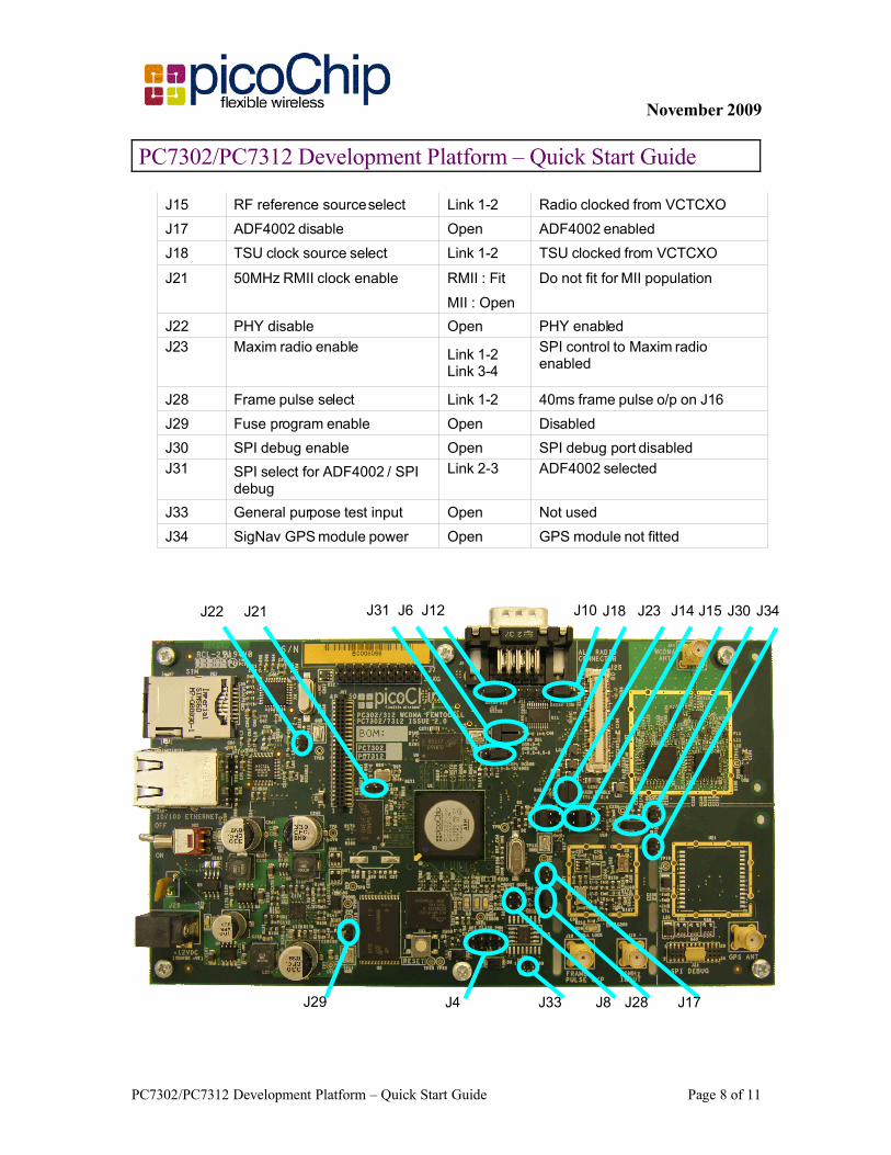
J15 RF reference source select Link 1-2 Radio clocked from VCTCXO
J17 ADF4002 disable Open ADF4002 enabled
J18 TSU clock source select Link 1-2 TSU clocked from VCTCXO
J21 50MHz RMII clock enable RMII : Fit Do not fit for MII population
MII : Open
J22 PHY disable Open PHY enabled
J23 Maxim radio enable Link 1-2 Link 3-4
SPI control to Maxim radio enabled
J28 Frame pulse select Link 1-2 40ms frame pulse o/p on J16
J29 Fuse program enable Open Disabled
J30 SPI debug enable Open SPI debug port disabled
J31 SPI select for ADF4002 / SPI debug
Link 2-3 ADF4002 selected
J33 General purpose test input Open Not used
J34 SigNav GPS module power Open GPS module not fitted
PC7302/PC7312 Development Platform – Quick Start Guide Page 8 of 11
J4
J6
J8
J12 J10 J14 J15
J17
J18J21J22 J23
J29 J28J33
J31 J30 J34
November 2009
PC7302/PC7312 Development Platform – Quick Start Guide
Table 4: RS232 settings
Parameter Setting
Baud rate 115200
Number of data bits 8
Parity None
Stop bits 1
Flow control None
The final configuration is shown in Figure 2 below.
Figure 2: PC7302/PC7312 hardware setup
2.4.Switching onIf not already powered up, switch on the mains power supply – LED5 (green) should be lit indicating presence of 12V at the input connector.
Switch on power to the PC7302 by setting SW2 to “ON” – LED4 (green) should be lit indicating presence of 3.3V at the output of the on-baord power supply.
Once the board has booted successfully, LED3 (red) should be off indicating that the PC302 is configured correctly. If LED3 remains on, check the installation of the J8 boot mode jumpers.
2.5.InitializationAs already discussed, the PC7302 comes fully configured to support code development for the PC302. This requires a development computer connected to the same sub-net with the picoTools installed [3]. To set the IP address of the PC7302:
Reboot the board by pressing the reset switch (SW1)
Stop the PC7302 booting into Linux by pressing any key, resulting in the U-Boot prompt.
Type the following at the U-Boot command prompt to change the IP address (where xxx.xxx.xxx.xxx is the new address)1:
set ipaddr xxx.xxx.xxx.xxx
To write the address back into Flash, type the following at the U-Boot command prompt:
saveenv
The network mask can be set in a similar manner:
set netmask xxx.xxx.xxx.xxx
1 Default address is 172.17.9.nnn.
PC7302/PC7312 Development Platform – Quick Start Guide Page 9 of 11
November 2009
PC7302/PC7312 Development Platform – Quick Start Guide
saveenv
Note that modification of the IP address and/or netmask results in an update of U-Boot environment variables.
Reboot the PC7302 by pressing the reset switch (SW1).
The settings of the IP address and network mask can be confirmed after boot by typing the following at the U-Boot prompt:
Printenv
Following any re-configuration, re-boot into Linux using the following credentials:
User: root
Password: picohdp
2.6.Ethernet ConnectionTo check that the Ethernet connection is working correctly, ping a valid IP address in the terminal window from the U-Boot command prompt (after halting the boot by pressing any key when requested). It is not possible to ping in to the board from an external source while U-Boot is running; once the Linux kernel has been loaded and is running external sources can ping the board.
1 TroubleshootingFor any problems setting up and initialising the PC7302, please contact the picoChip applications team on [email protected].
2 References
1. PC7302 Development Board Datasheet
2. PC7302 Board Support Package documentation
3. picoTools Documentation.
4. The PC302/PC312 Programmers Guide.
5. PC302/PC312 Datasheet
3 Glossary
BOM Bill of MaterialsEEPROM Electronically Erasable Programmable Read-Only MemoryGPIO General Purpose Input OutputLED Light Emitting DiodeIP Internet Protocol
PC7302/PC7312 Development Platform – Quick Start Guide Page 10 of 11


![DSP ML 54582_20080331_AA_entire_text[1] (1)](https://static.documents.pub/doc/80x56/553e408755034655428b498d/dsp-ml-5458220080331aaentiretext1-1.jpg)

![Parts Catalog ML-331x 371x Series[1]](https://static.documents.pub/doc/80x56/5533bad35503464f7d8b49de/parts-catalog-ml-331x-371x-series1.jpg)


![PC 811 TroubleshootingGuide[1]](https://static.documents.pub/doc/80x56/5533585c550346e1028b48a0/pc-811-troubleshootingguide1.jpg)


