18
Fig1: Scheme for micro PLC to Master PLC Interface Filed Instrument HMI Master PLC Micro PLC Switches Server/ Engineering Station PC Filed Instrument Filed Instrument
HMI
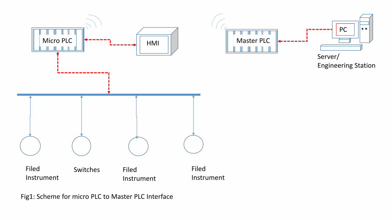
Fig1: Scheme for micro PLC to Master PLC Interface
Filed Instrument
HMI Master PLC Micro PLC
Switches
Server/ Engineering Station
PC
Filed Instrument
Filed Instrument
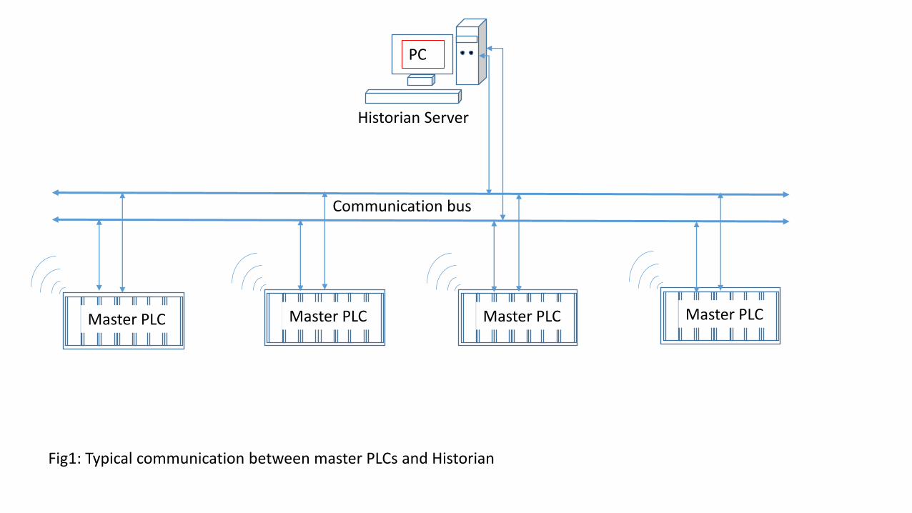
Fig1: Typical communication between master PLCs and Historian
Master PLC
Historian Server
PC
Master PLC Master PLC Master PLC
Communication bus
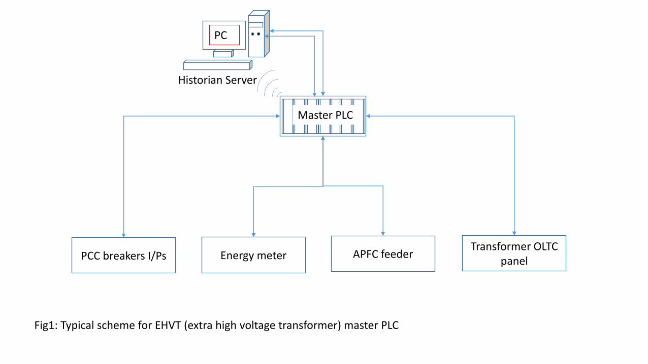
Fig1: Typical scheme for EHVT (extra high voltage transformer) master PLC
Master PLC
Historian Server
PC
PCC breakers I/Ps Energy meter APFC feeder Transformer OLTC
panel
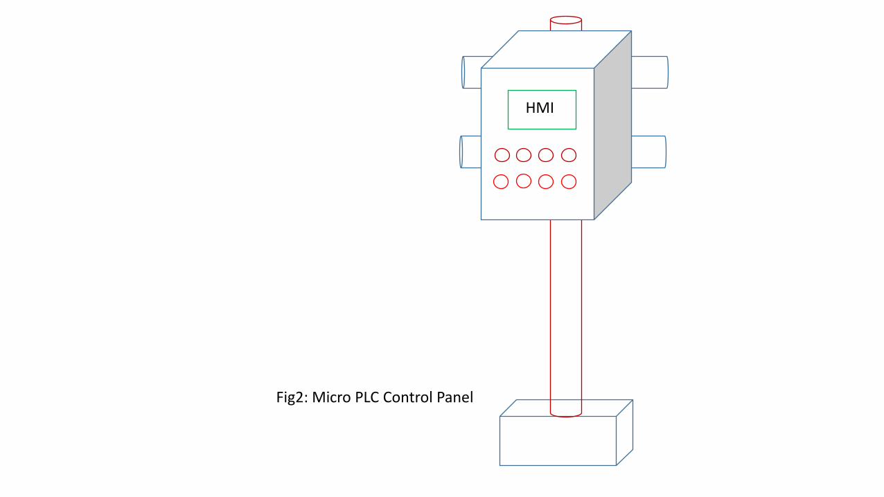
HMI
Fig2: Micro PLC Control Panel
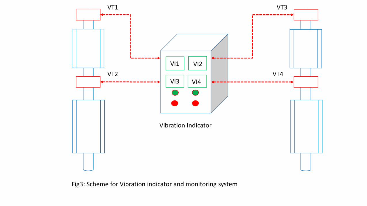
Fig3: Scheme for Vibration indicator and monitoring system
VI1 VI2
VI4 VI3
VT1
VT2 VT4
VT3
Vibration Indicator
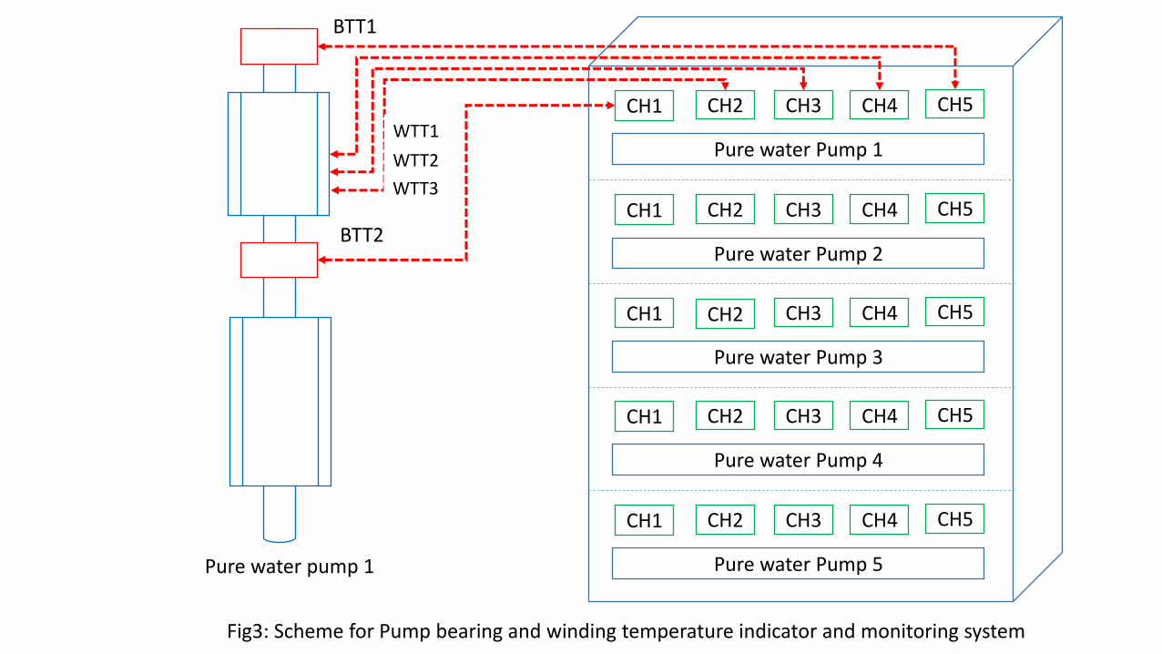
Fig3: Scheme for Pump bearing and winding temperature indicator and monitoring system
BTT2
Pure water Pump 1
CH1 CH2 CH3 CH4 CH5
Pure water Pump 2
CH1 CH2 CH3 CH4 CH5
Pure water Pump 3
CH1 CH2 CH3 CH4 CH5
Pure water Pump 4
CH1 CH2 CH3 CH4 CH5
Pure water Pump 5
CH1 CH2 CH3 CH4 CH5
BTT1
WTT1
WTT2
WTT3
Pure water pump 1
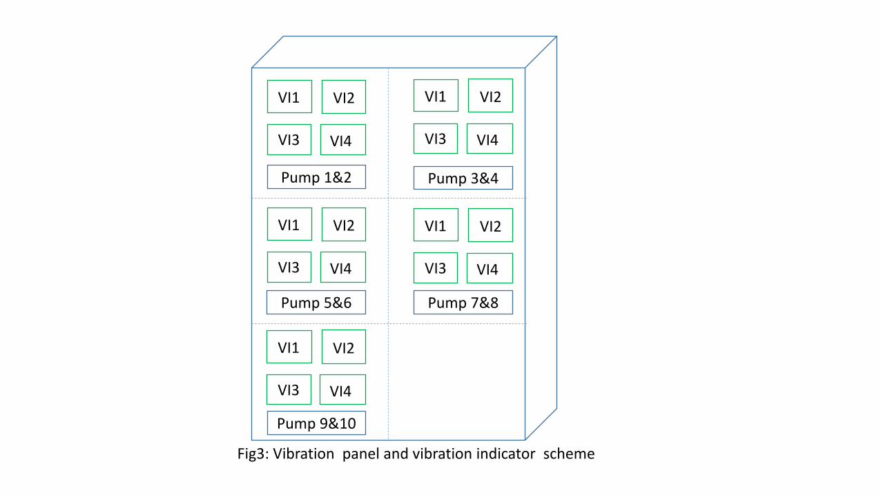
Fig3: Vibration panel and vibration indicator scheme
VI1 VI2
VI4 VI3
Pump 1&2 Pump 3&4
Pump 7&8 Pump 5&6
Pump 9&10
VI1 VI2
VI4 VI3
VI1 VI2
VI4 VI3
VI1 VI2
VI4 VI3
VI1 VI2
VI4 VI3
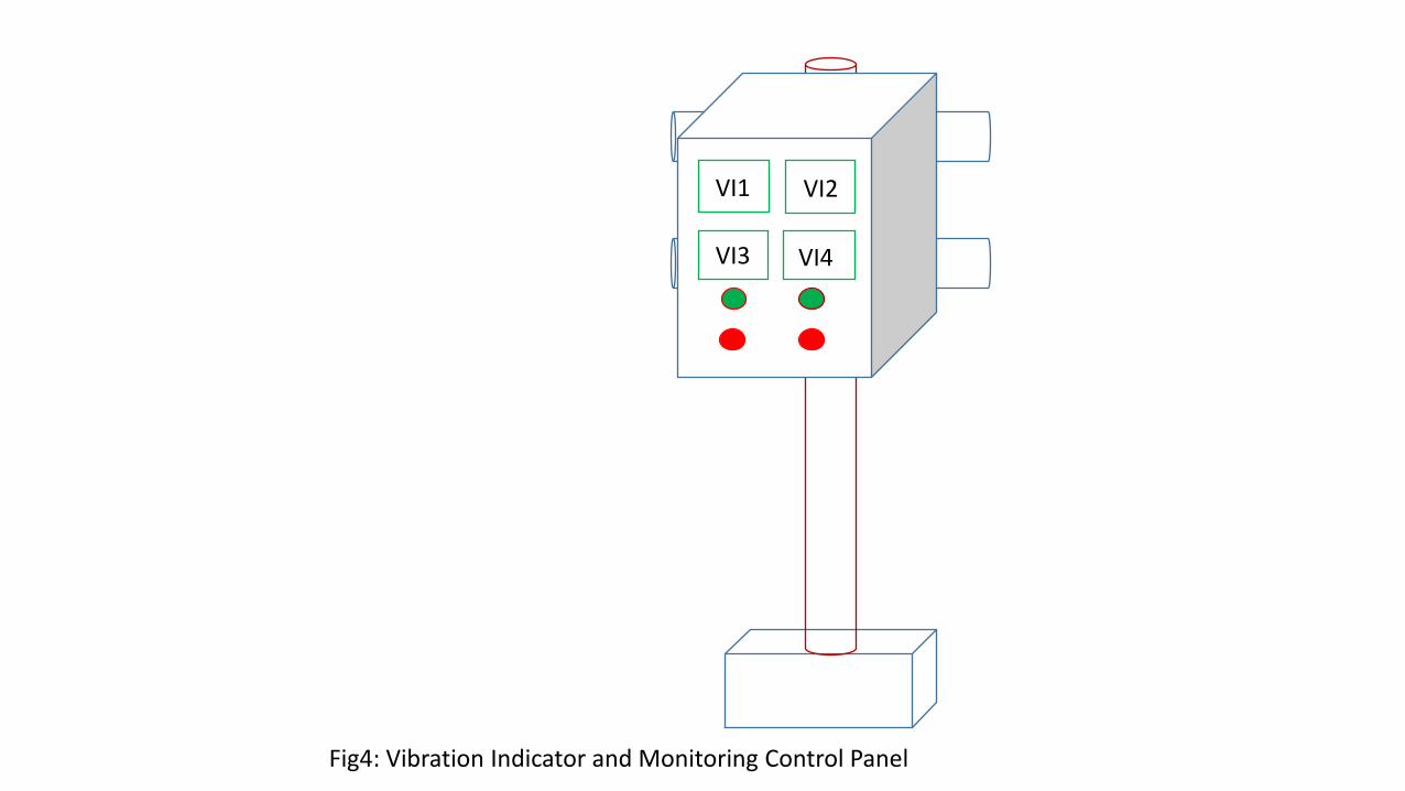
Fig4: Vibration Indicator and Monitoring Control Panel
VI1 VI2
VI4 VI3
Micro PLC #1
Micro PLC #2
Micro PLC #12
Micro PLC #13
Master PLC
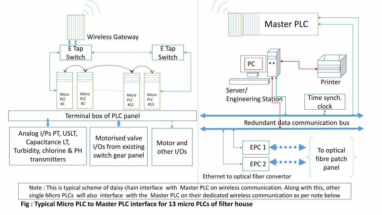
Fig : Typical Micro PLC to Master PLC interface for 13 micro PLCs of filter house
E Tap Switch
E Tap Switch
Wireless Gateway
Note : This is typical scheme of daisy chain interface with Master PLC on wireless communication. Along with this, other single Micro PLCs will also interface with the Master PLC on their dedicated wireless communication as per note below
Terminal box of PLC panel
Analog I/Ps PT, USLT, Capacitance LT,
Turbidity, chlorine & PH transmitters
Motorised valve I/Os from existing switch gear panel
Motor and other I/Os
Server/ Engineering Station
PC
Printer
Redundant data communication bus
EPC 1
EPC 2
To optical fibre patch
panel Ethernet to optical fiber convertor
Time synch. clock
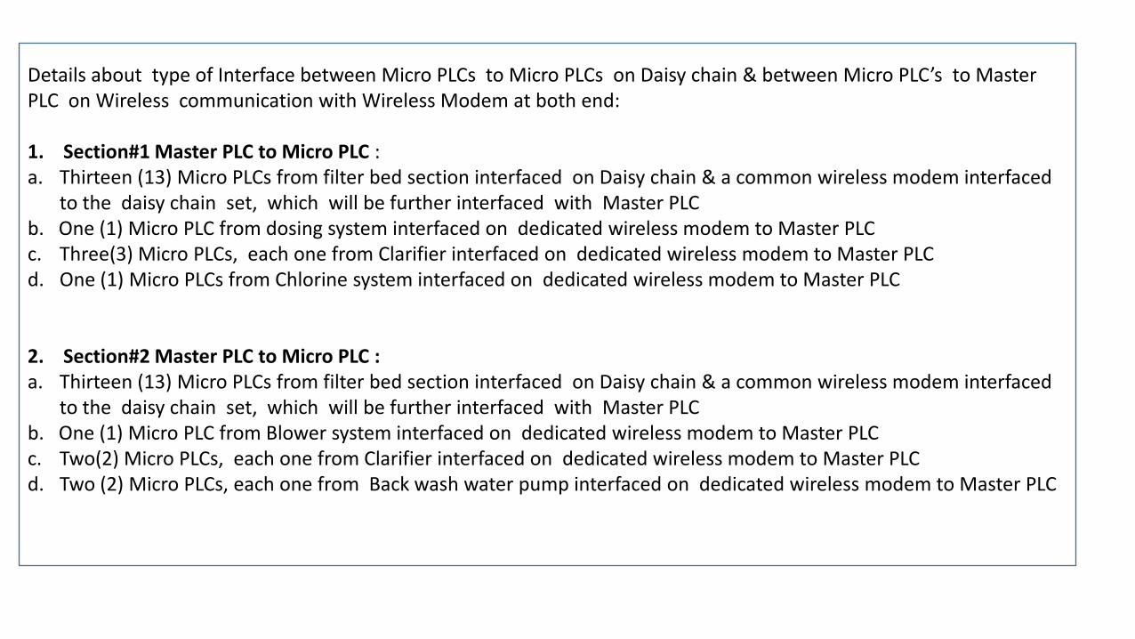
Details about type of Interface between Micro PLCs to Micro PLCs on Daisy chain & between Micro PLC’s to Master PLC on Wireless communication with Wireless Modem at both end: 1. Section#1 Master PLC to Micro PLC : a. Thirteen (13) Micro PLCs from filter bed section interfaced on Daisy chain & a common wireless modem interfaced
to the daisy chain set, which will be further interfaced with Master PLC b. One (1) Micro PLC from dosing system interfaced on dedicated wireless modem to Master PLC c. Three(3) Micro PLCs, each one from Clarifier interfaced on dedicated wireless modem to Master PLC d. One (1) Micro PLCs from Chlorine system interfaced on dedicated wireless modem to Master PLC 2. Section#2 Master PLC to Micro PLC : a. Thirteen (13) Micro PLCs from filter bed section interfaced on Daisy chain & a common wireless modem interfaced
to the daisy chain set, which will be further interfaced with Master PLC b. One (1) Micro PLC from Blower system interfaced on dedicated wireless modem to Master PLC c. Two(2) Micro PLCs, each one from Clarifier interfaced on dedicated wireless modem to Master PLC d. Two (2) Micro PLCs, each one from Back wash water pump interfaced on dedicated wireless modem to Master PLC
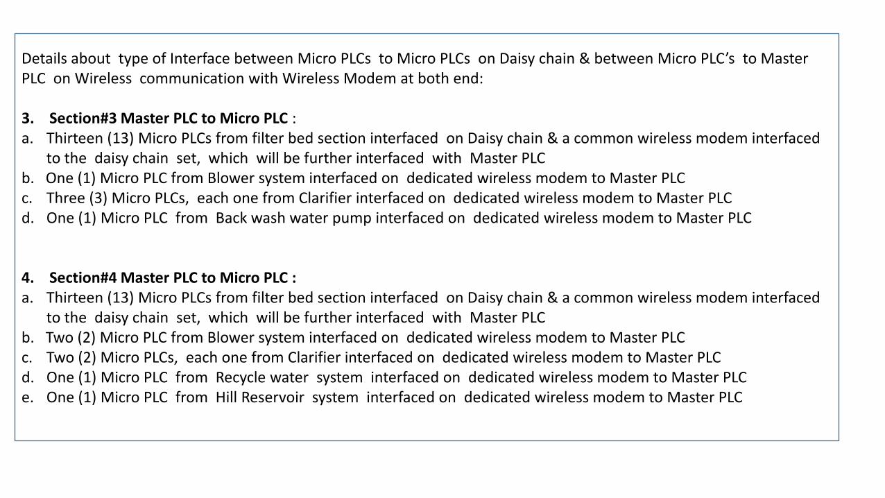
Details about type of Interface between Micro PLCs to Micro PLCs on Daisy chain & between Micro PLC’s to Master PLC on Wireless communication with Wireless Modem at both end: 3. Section#3 Master PLC to Micro PLC : a. Thirteen (13) Micro PLCs from filter bed section interfaced on Daisy chain & a common wireless modem interfaced
to the daisy chain set, which will be further interfaced with Master PLC b. One (1) Micro PLC from Blower system interfaced on dedicated wireless modem to Master PLC c. Three (3) Micro PLCs, each one from Clarifier interfaced on dedicated wireless modem to Master PLC d. One (1) Micro PLC from Back wash water pump interfaced on dedicated wireless modem to Master PLC 4. Section#4 Master PLC to Micro PLC : a. Thirteen (13) Micro PLCs from filter bed section interfaced on Daisy chain & a common wireless modem interfaced
to the daisy chain set, which will be further interfaced with Master PLC b. Two (2) Micro PLC from Blower system interfaced on dedicated wireless modem to Master PLC c. Two (2) Micro PLCs, each one from Clarifier interfaced on dedicated wireless modem to Master PLC d. One (1) Micro PLC from Recycle water system interfaced on dedicated wireless modem to Master PLC e. One (1) Micro PLC from Hill Reservoir system interfaced on dedicated wireless modem to Master PLC
Micro PLC
Master PLC
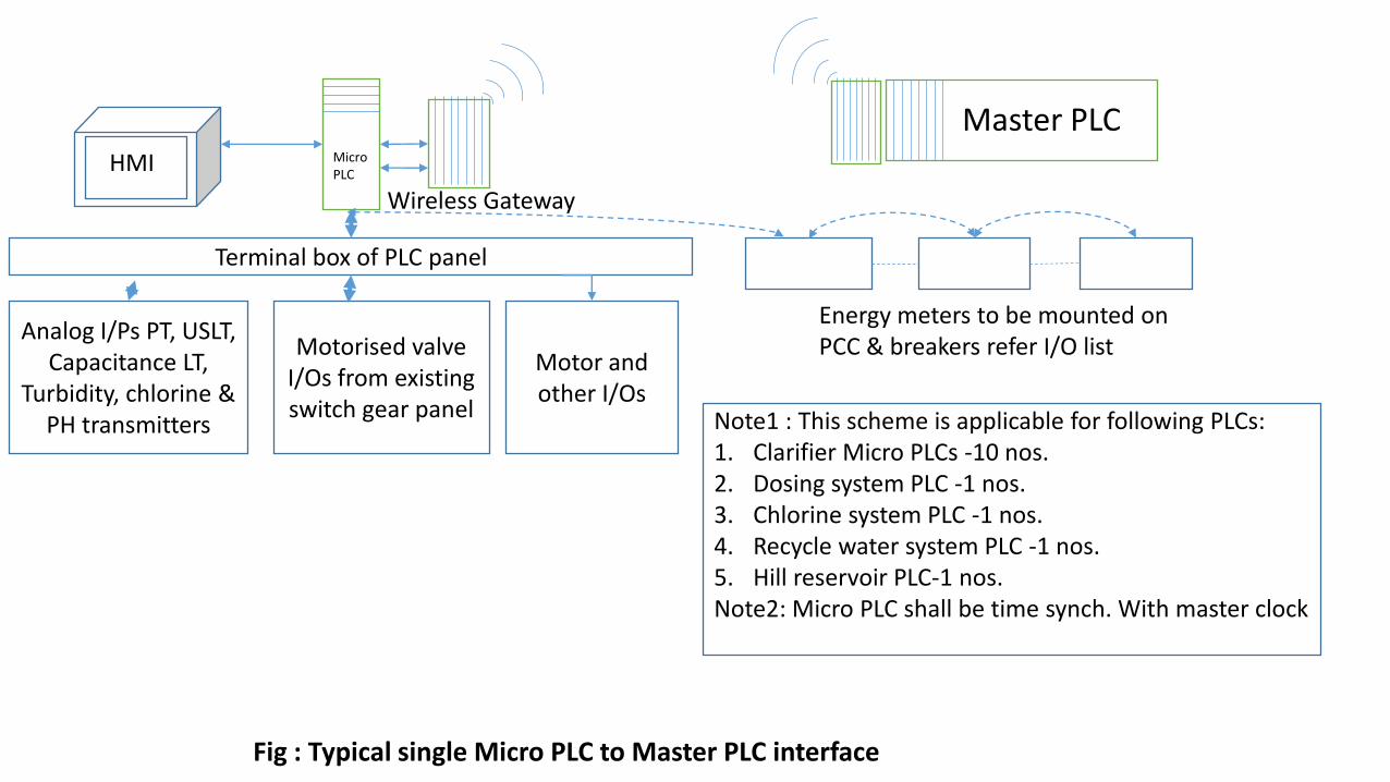
Fig : Typical single Micro PLC to Master PLC interface
Wireless Gateway
HMI HMI
Terminal box of PLC panel
Analog I/Ps PT, USLT, Capacitance LT,
Turbidity, chlorine & PH transmitters
Motorised valve I/Os from existing switch gear panel
Motor and other I/Os
Energy meters to be mounted on PCC & breakers refer I/O list
Note1 : This scheme is applicable for following PLCs: 1. Clarifier Micro PLCs -10 nos. 2. Dosing system PLC -1 nos. 3. Chlorine system PLC -1 nos. 4. Recycle water system PLC -1 nos. 5. Hill reservoir PLC-1 nos. Note2: Micro PLC shall be time synch. With master clock
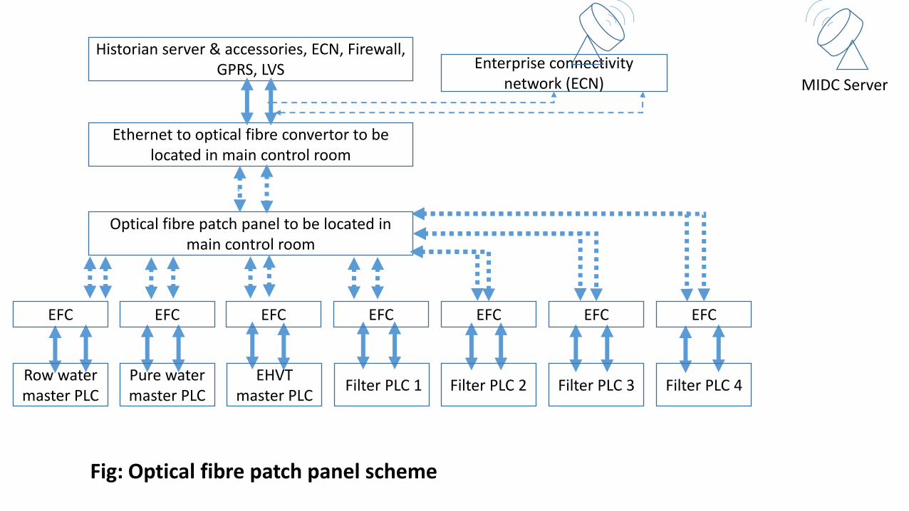
Fig: Optical fibre patch panel scheme
Enterprise connectivity network (ECN)
Historian server & accessories, ECN, Firewall, GPRS, LVS
Ethernet to optical fibre convertor to be located in main control room
Optical fibre patch panel to be located in main control room
EFC EFC EFC EFC EFC EFC EFC
Row water master PLC
Pure water master PLC
EHVT master PLC
Filter PLC 1 Filter PLC 2 Filter PLC 3 Filter PLC 4
MIDC Server
Server/ Engineering Station
PC
Printer
Redundant data communication bus
EPC 1
EPC 2
To optical fibre patch
panel
Ethernet to optical fibre convertor
PLC CPU
Redundant I/O Bus
I/P Module O/P Module RS-485 TCP/IP
convertor
Relay cards
Terminal box of PLC panel
I/P’s from PCC, switch gear,
breakers & alarm
I/P from transformer
OLTC
O/P to control PCC breakers
Energy meters to be mounted on PCC & breakers refer I/O list
Time synchronization clock
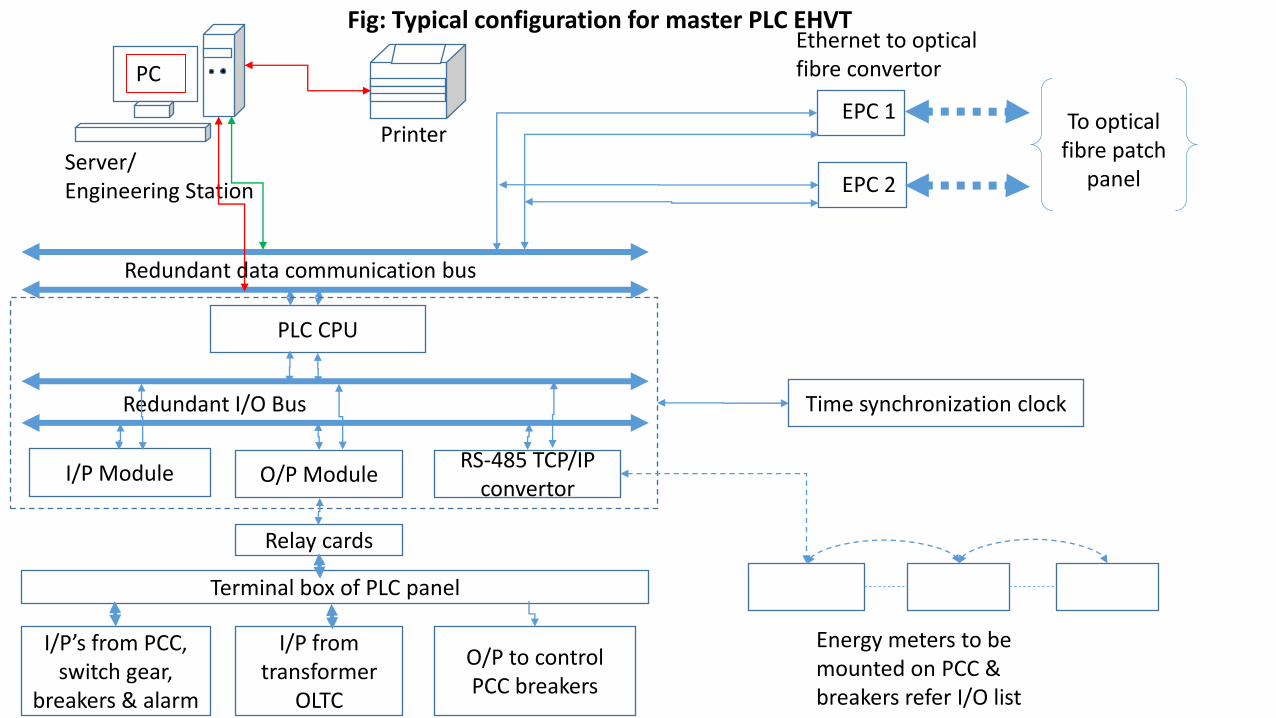
Fig: Typical configuration for master PLC EHVT
Server/ Engineering Station
PC
Printer
Redundant data communication bus
EPC 1
EPC 2
To optical fibre patch
panel
Ethernet to optical fibre convertor
PLC CPU
Redundant I/O Bus
I/P Module O/P Module RS-485 TCP/IP
convertor
Relay cards
Terminal box of PLC panel
JB. Discrete I/Ps likre PR. Switch
at etc.
Analog JB. PT,EMF,USLT, BTD,
WTD, vibration
JB. Pump motor and motorised
actuators
Energy meters to be mounted on PCC & breakers refer I/O list
Time synchronization clock
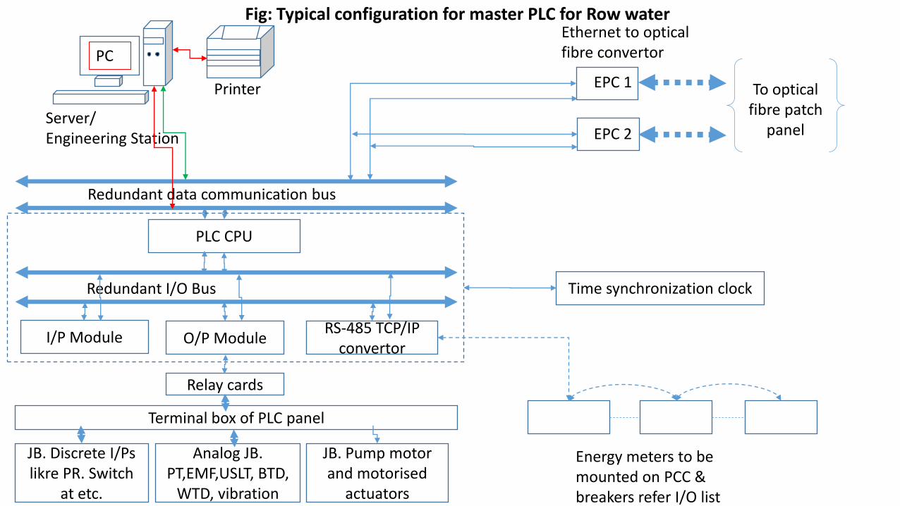
Fig: Typical configuration for master PLC for Row water
Server/ Engineering Station
PC
Printer
Redundant data communication bus
EPC 1
EPC 2
To optical fibre patch
panel
Ethernet to optical fibre convertor
PLC CPU
Redundant I/O Bus
I/P Module O/P Module RS-485 TCP/IP
convertor
Relay cards
Terminal box of PLC panel
JB. Discrete I/Ps likre PR. Switch
at etc.
Analog JB. PT,EMF,USLT, BTD, turbidity, PH,
Chlorine WTD, vibration
JB. Pump motor and motorised
actuators
Energy meters to be mounted on PCC & breakers refer I/O list
Time synchronization clock
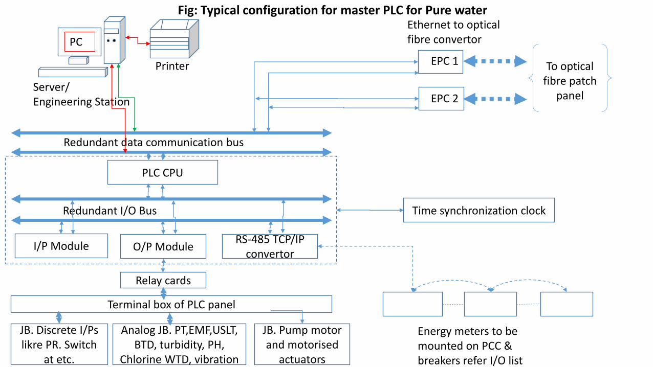
Fig: Typical configuration for master PLC for Pure water
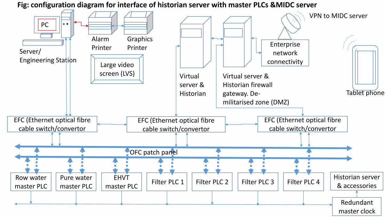
Fig: configuration diagram for interface of historian server with master PLCs &MIDC server
Row water master PLC
Pure water master PLC
EHVT master PLC
Filter PLC 1 Filter PLC 2 Filter PLC 3 Filter PLC 4
Redundant master clock
Historian server & accessories
EFC (Ethernet optical fibre cable switch/convertor
EFC (Ethernet optical fibre cable switch/convertor
EFC (Ethernet optical fibre cable switch/convertor
Server/ Engineering Station
PC
Alarm Printer
Large video screen (LVS)
Graphics Printer
Virtual server & Historian
Virtual server & Historian firewall gateway. De- militarised zone (DMZ)
Enterprise network
connectivity
VPN to MIDC server
OFC patch panel
Tablet phone
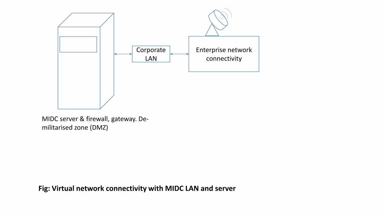
MIDC server & firewall, gateway. De- militarised zone (DMZ)
Enterprise network connectivity
Corporate LAN
Fig: Virtual network connectivity with MIDC LAN and server


![FA Equipment for Beginners(HMIs) THA.ppt [互換モード]...HMI tq:fu GT Simulator3 Mitsubishi Electric PC HMI RS-232C PC USB HMI PLC 000 HMI PLC FA Equipment for Beginners(HMIs)](https://static.documents.pub/doc/80x56/5e459b24cf716854423e8a33/fa-equipment-for-beginnershmis-thappt-fff-hmi-tqfu-gt-simulator3.jpg)


