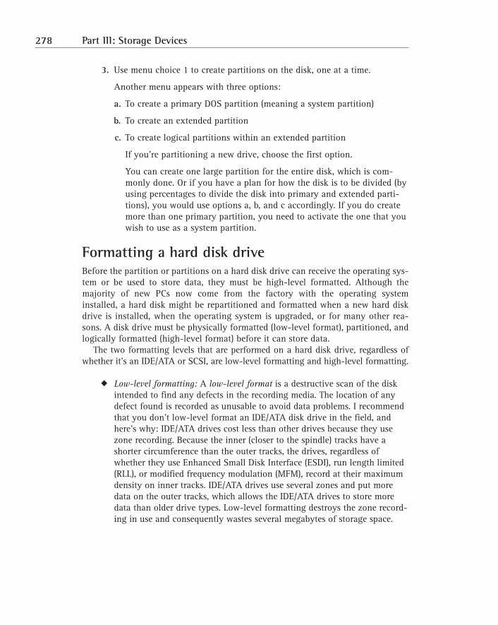
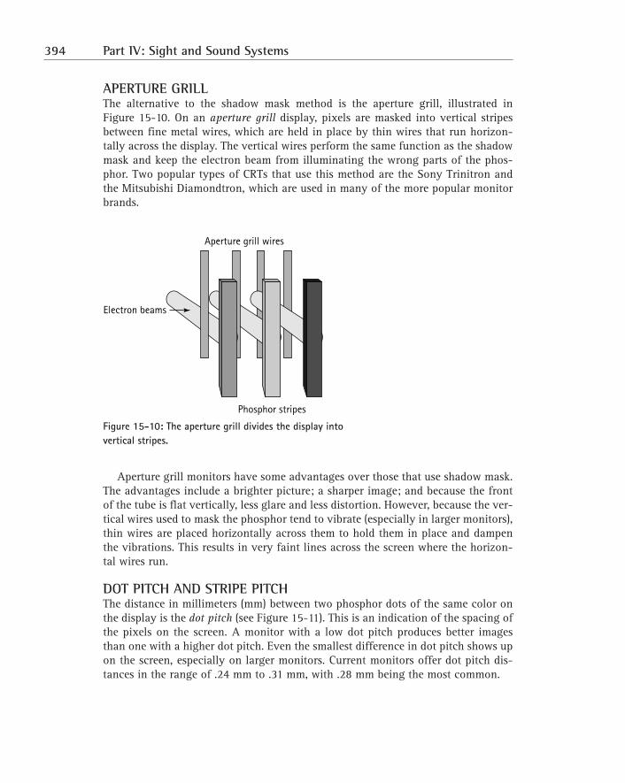
Figure 7-3: A Cache on a Stick (COAST) module. Working with Cache In a vast majority of cases, you wouldn’t be adding cache memory to a PC. However, if you find it necessary, the guidelines in the following sections should provide you with some help. Installing a cache module First, review the motherboard’s documentation or check with the PC manufacturer or vendor to determine whether the PC is able to expand its L2 cache. If no caching is installed and you wish to include caching, use the motherboard’s specifications to select the correct SRAM chips of COAST module. Most newer motherboards don’t have a cache slot when the cache module is installed. It is very common on motherboards to find cache sockets instead of a cache module slot or the CELP socket. To install a COAST module: 1. Place the motherboard on a flat, solid, clean, and static-free work surface. Place the motherboard so that it won’t flex or bend when you press the caching module or chips into their sockets. 2. Before installing the module into the socket, line it up with the socket to visually match the pins of the edge-connector to the socket connectors. Cache (COAST) modules are usually keyed, which means that they have a guide pin or relief feature on the leading edge of the connector that mates to a receptacle or slot on the socket to prevent being inserted into a socket incorrectly. 3. Place the module into the socket slot and press down gently but firmly until the module seats into the slot. If the module won’t seat easily, try first gently pressing down on one end of the module and then the other end until it begins to set into the slot. The module is seated when the edge-connectors are most of the way into the socket and the module will not fit farther into the socket under firm pressure. SRAM SRAM TAG- RAM PIN80 PIN43 PIN42 PIN1 182 Part I: The Motherboard and Its Components
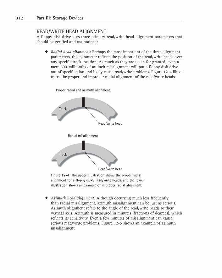
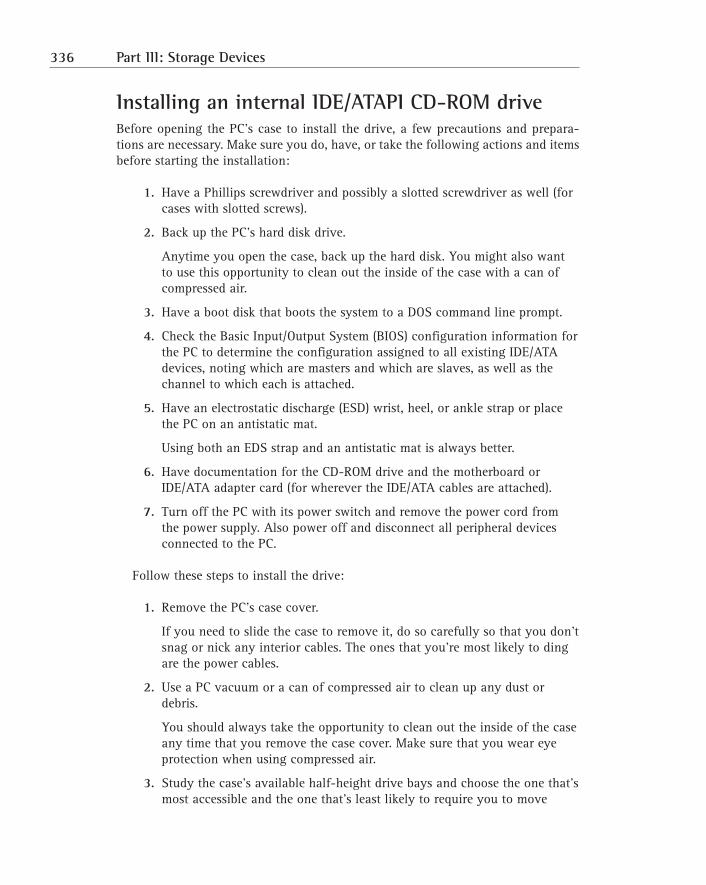
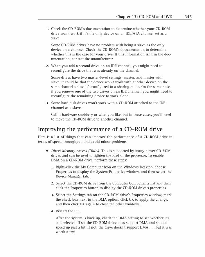
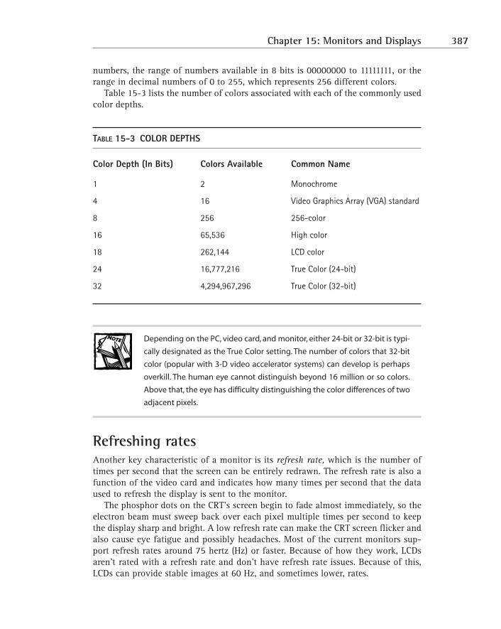
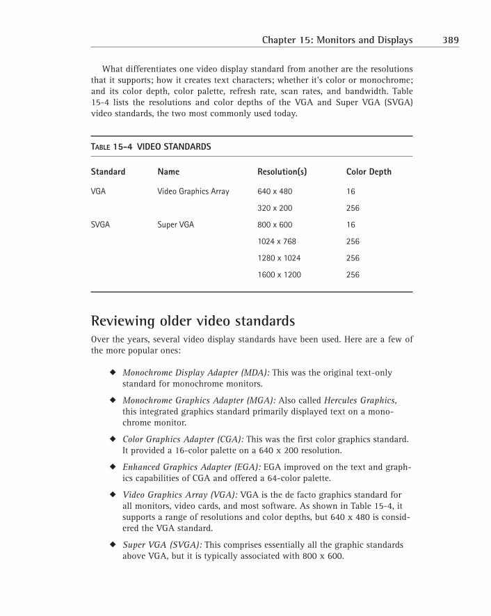
Transcript
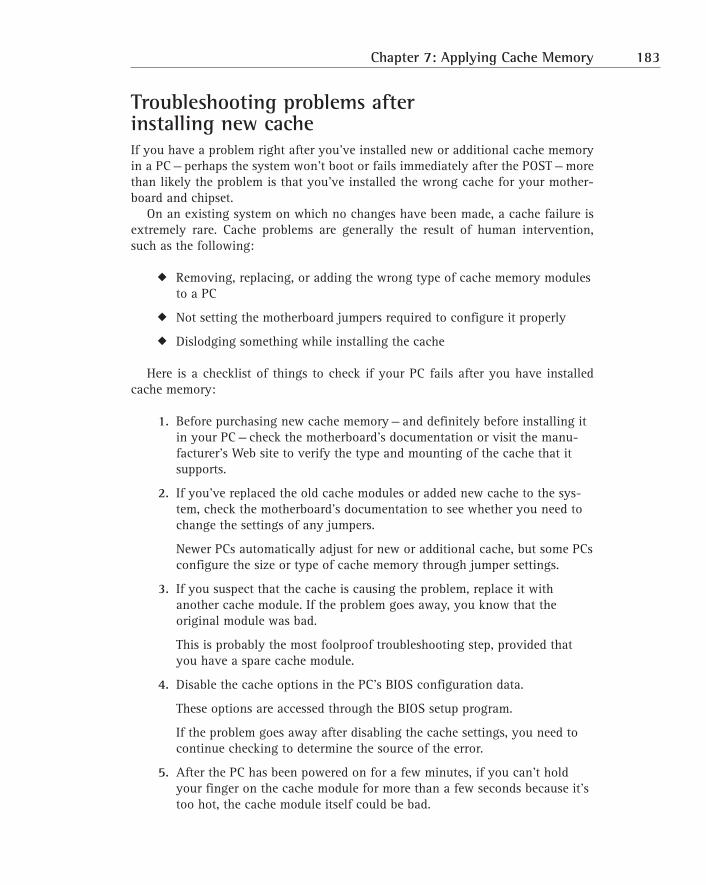
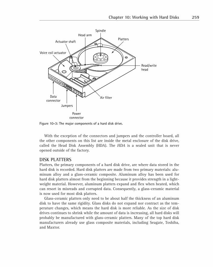
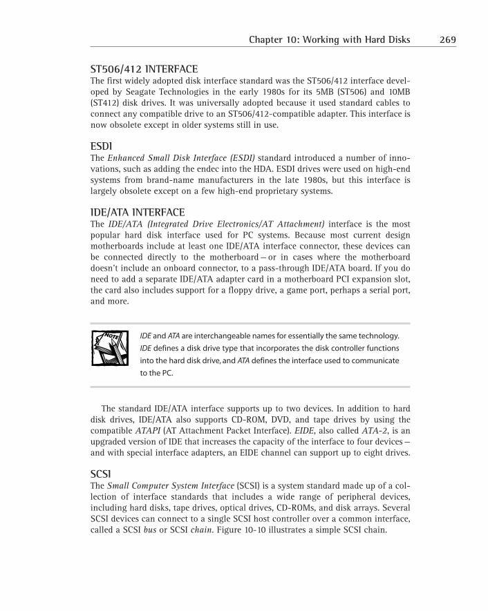
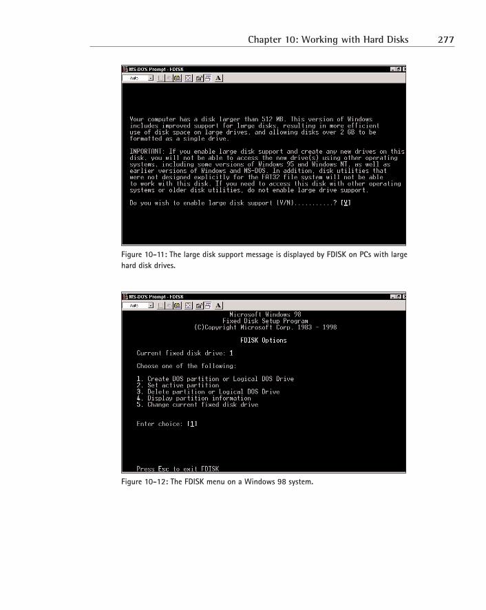
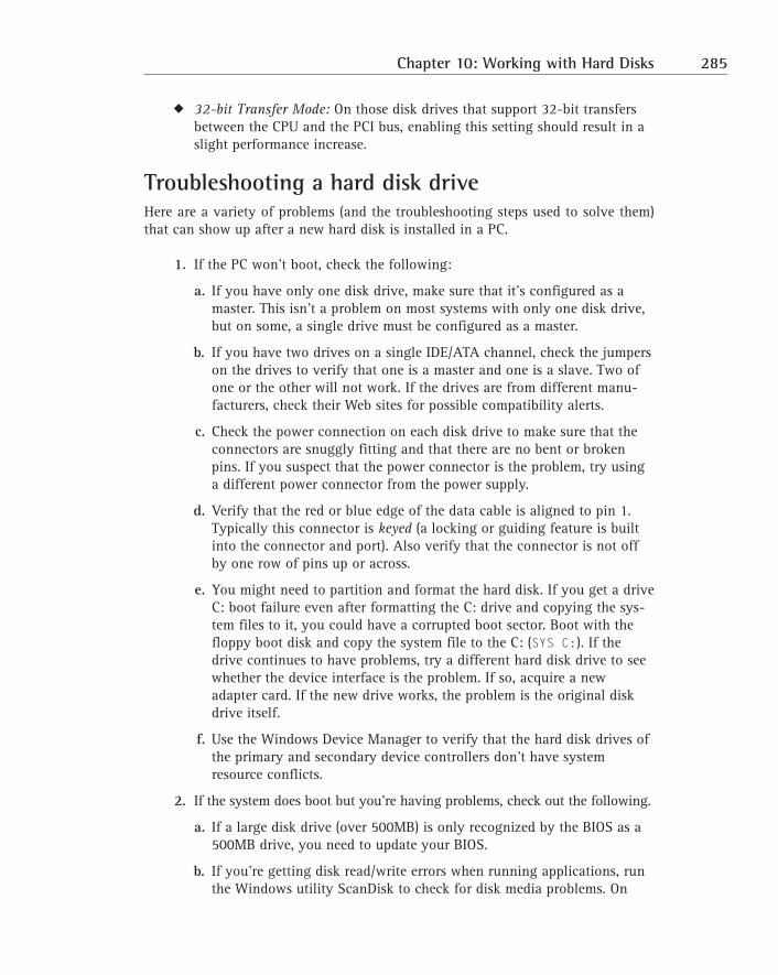
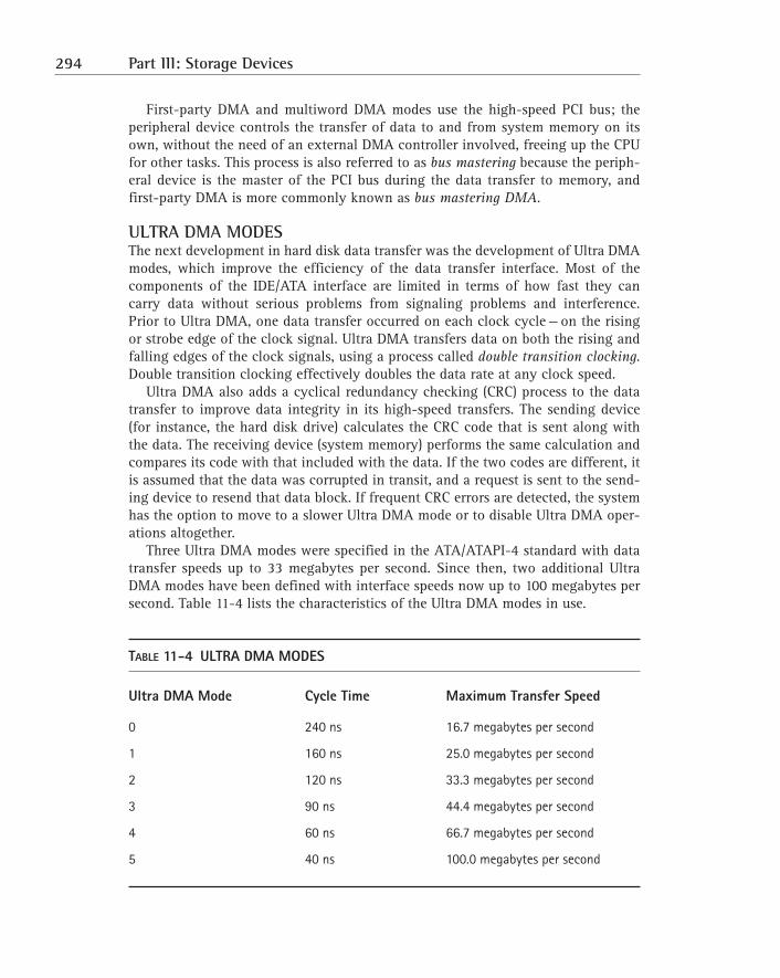
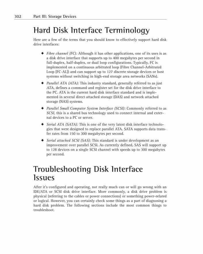
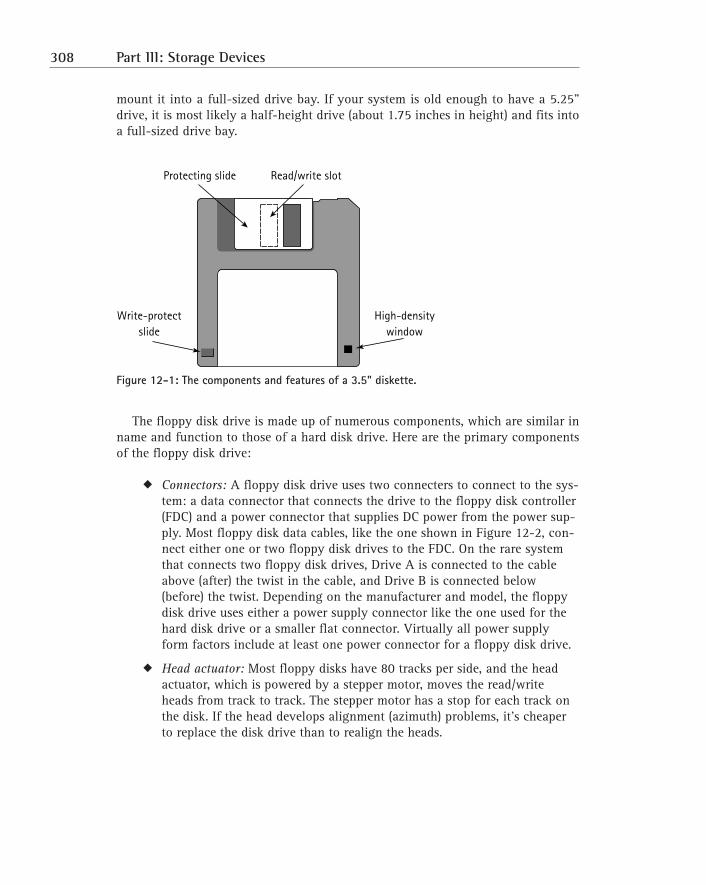
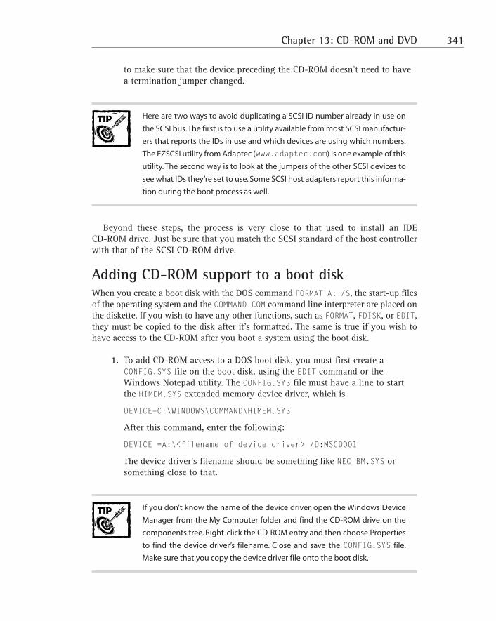
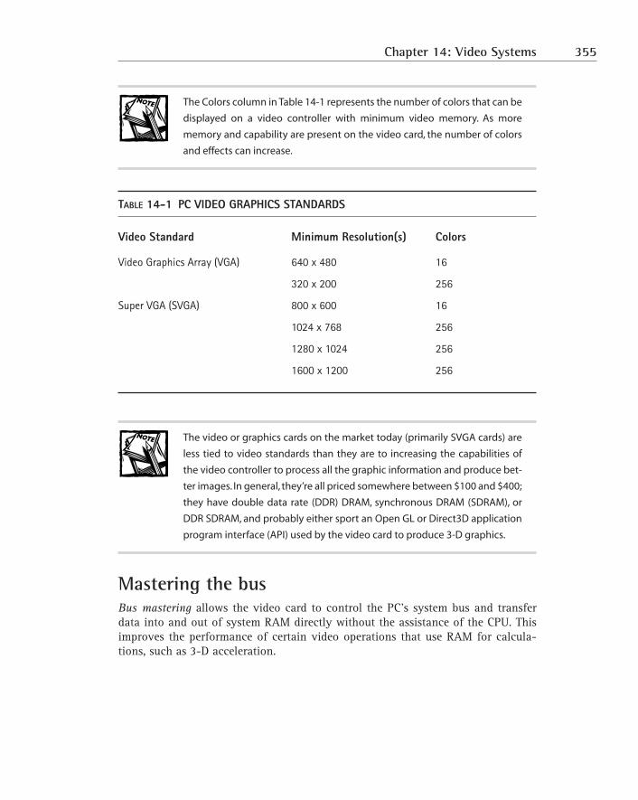
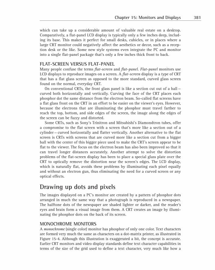
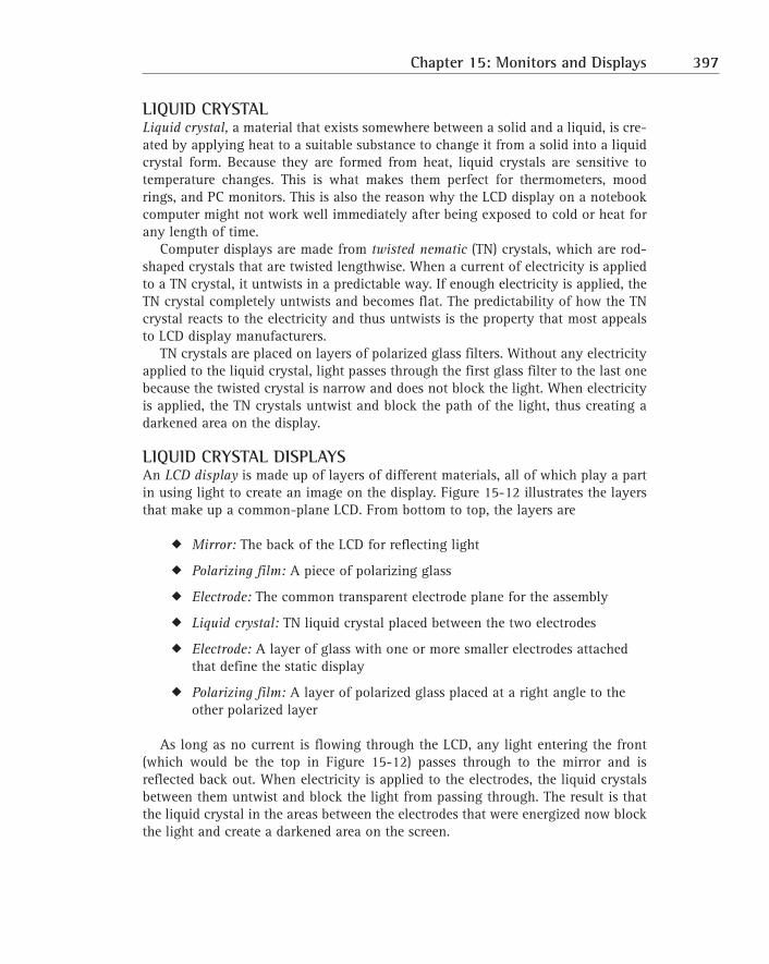
Figure 7-3: A Cache on a Stick (COAST) module.
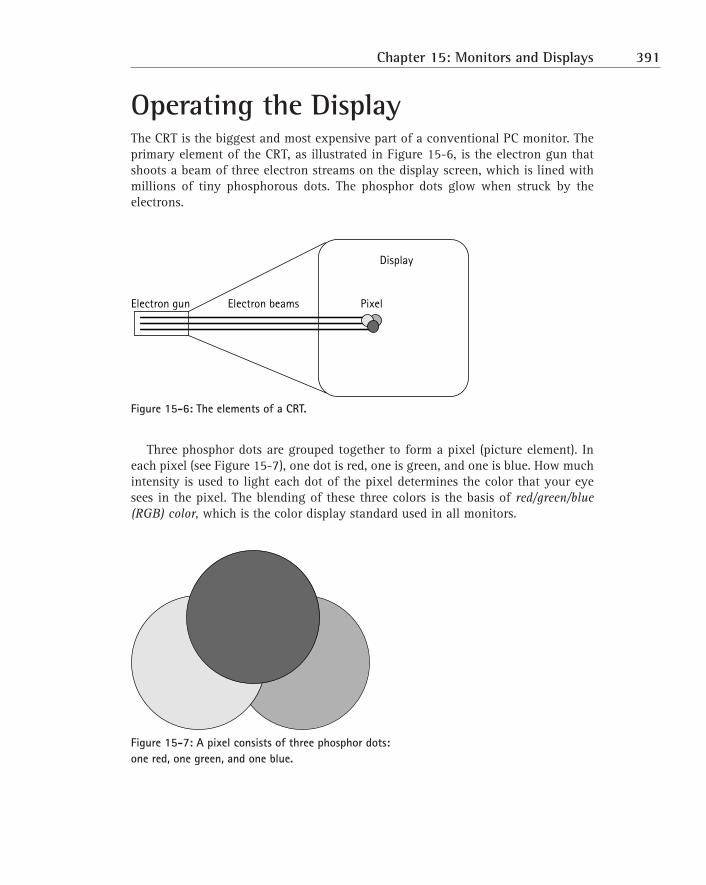
Working with CacheIn a vast majority of cases, you wouldn’t be adding cache memory to a PC.However, if you find it necessary, the guidelines in the following sections shouldprovide you with some help.
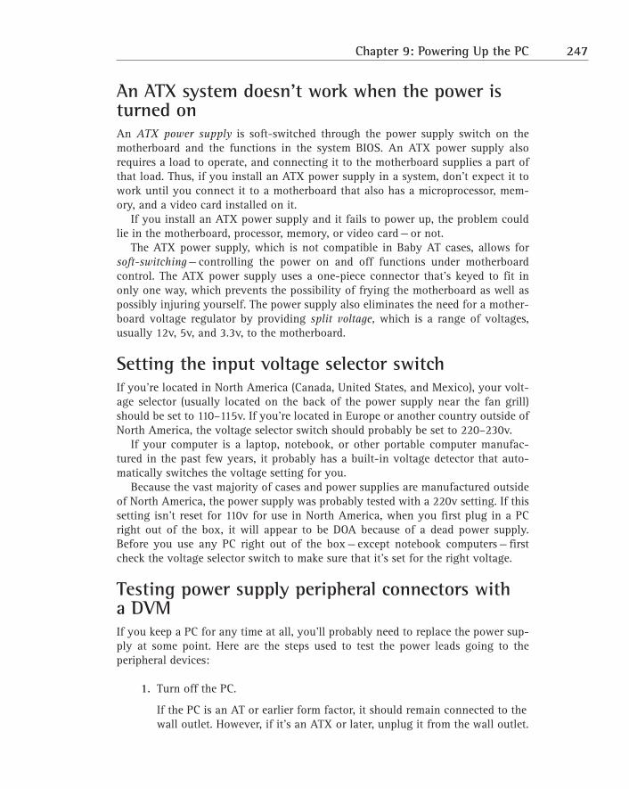
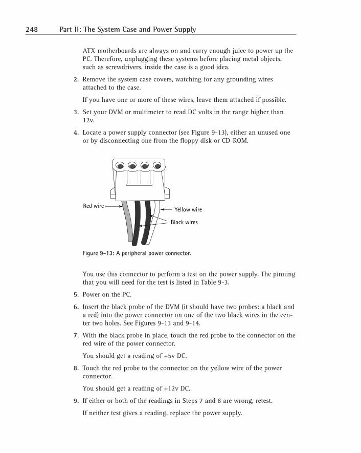
Installing a cache moduleFirst, review the motherboard’s documentation or check with the PC manufactureror vendor to determine whether the PC is able to expand its L2 cache. If no cachingis installed and you wish to include caching, use the motherboard’s specificationsto select the correct SRAM chips of COAST module.
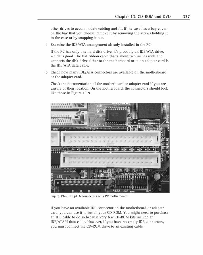
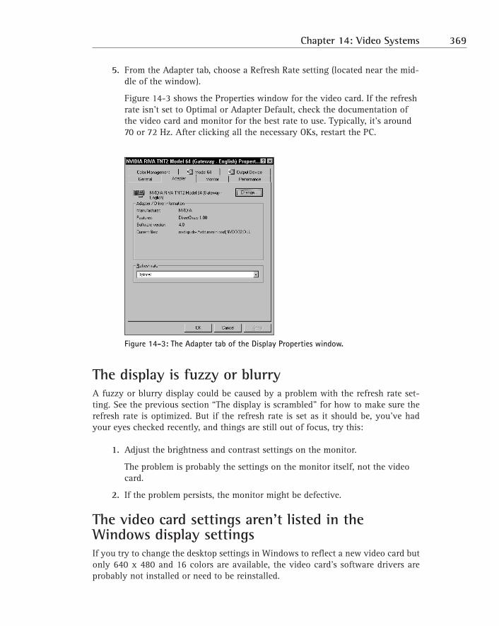
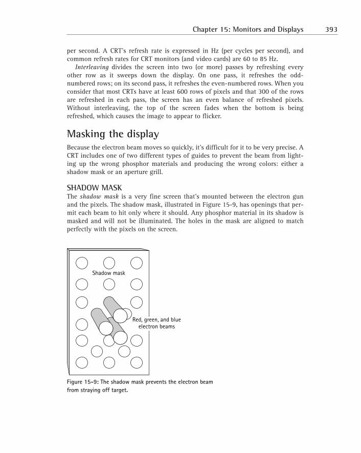
Most newer motherboards don’t have a cache slot when the cache module isinstalled. It is very common on motherboards to find cache sockets instead of acache module slot or the CELP socket. To install a COAST module:
1. Place the motherboard on a flat, solid, clean, and static-free work surface.
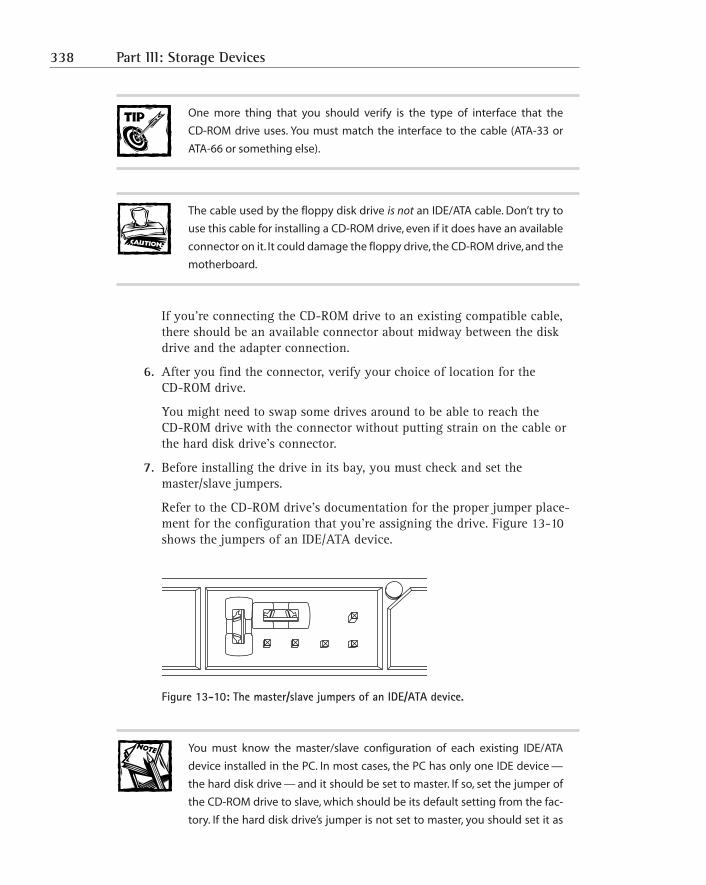
Place the motherboard so that it won’t flex or bend when you press thecaching module or chips into their sockets.
2. Before installing the module into the socket, line it up with the socket tovisually match the pins of the edge-connector to the socket connectors.
Cache (COAST) modules are usually keyed, which means that they have aguide pin or relief feature on the leading edge of the connector that matesto a receptacle or slot on the socket to prevent being inserted into a socketincorrectly.
3. Place the module into the socket slot and press down gently but firmlyuntil the module seats into the slot.
If the module won’t seat easily, try first gently pressing down on one endof the module and then the other end until it begins to set into the slot.The module is seated when the edge-connectors are most of the way intothe socket and the module will not fit farther into the socket under firmpressure.
SRAM SRAMTAG-RAM
PIN80 PIN43 PIN42 PIN1
182 Part I: The Motherboard and Its Components
Troubleshooting problems after installing new cacheIf you have a problem right after you’ve installed new or additional cache memoryin a PC — perhaps the system won’t boot or fails immediately after the POST — morethan likely the problem is that you’ve installed the wrong cache for your mother-board and chipset.
On an existing system on which no changes have been made, a cache failure isextremely rare. Cache problems are generally the result of human intervention,such as the following:
� Removing, replacing, or adding the wrong type of cache memory modulesto a PC
� Not setting the motherboard jumpers required to configure it properly
� Dislodging something while installing the cache
Here is a checklist of things to check if your PC fails after you have installedcache memory:
1. Before purchasing new cache memory — and definitely before installing itin your PC — check the motherboard’s documentation or visit the manu-facturer’s Web site to verify the type and mounting of the cache that itsupports.
2. If you’ve replaced the old cache modules or added new cache to the sys-tem, check the motherboard’s documentation to see whether you need tochange the settings of any jumpers.
Newer PCs automatically adjust for new or additional cache, but some PCsconfigure the size or type of cache memory through jumper settings.
3. If you suspect that the cache is causing the problem, replace it withanother cache module. If the problem goes away, you know that theoriginal module was bad.
This is probably the most foolproof troubleshooting step, provided thatyou have a spare cache module.
4. Disable the cache options in the PC’s BIOS configuration data.
These options are accessed through the BIOS setup program.
If the problem goes away after disabling the cache settings, you need tocontinue checking to determine the source of the error.
5. After the PC has been powered on for a few minutes, if you can’t holdyour finger on the cache module for more than a few seconds because it’stoo hot, the cache module itself could be bad.
Chapter 7: Applying Cache Memory 183
If the new module also gets too hot to touch after replacing the cachemodule, the motherboard is the likely problem. Re-verify that the cache isthe right type for the motherboard; and if so, test the motherboard.
6. Ensure that you’re using the correct cache memory type for your system.
If not, immediately remove and replace it.
Remember to check and change, if necessary, the cache memory optionsin the BIOS settings.
7. Verify that the cache is installed in its mounting correctly and that it’sproperly oriented and firmly seated in the socket or slot on the mother-board.
8. Check all drive and power supply connectors to see whether you acciden-tally unseated or dislodged one when installing the cache.
9. If you still cannot locate the problem, test the primary memory and checkfor any updated device drivers or software patches that have recently beeninstalled.
The problem could very well be coincidental and just happened to showup at this time.
Adding cache didn’t improve system performanceIt is a commonly held belief that adding more L2 cache will improve system perfor-mance. But what if you add more L2 cache (assuming that the installation is correctand uses the right type of cache memory), and the PC doesn’t seem to be perform-ing any better than it did before the cache was added?
If your PC already has 256KB of L2 cache and is already caching 90 percent orbetter of memory requests, the amount of improvement available is marginal, per-haps in the range of 5 to 10 percent. At the speed of the processor and SRAM, it’svery unlikely that you will notice this slight improvement.
On the other hand, it could be that the cache isn’t installed properly and isn’t beingrecognized by the PC—and that’s what is accounting for the lack of improvement.
Here are some steps that you can use to verify whether the cache is installed cor-rectly:
1. Check the BIOS display during the boot to determine how much cache isdetected and reported.
If it’s not the correct amount, check the cache modules to see whetherthey’re the right type for the motherboard or whether they’re installedcorrectly.
2. Check the motherboard’s documentation to see whether adding cachememory, especially more cache memory, requires jumpers to be changed.Then check the BIOS data for settings that might need to be changed.
184 Part I: The Motherboard and Its Components
3. If everything looks okay and checks out, use benchmark software (beforeand after the installation of the cache memory) and then compare theresults.
Even on the most efficient systems, you should see some improvement, nomatter how small it might be.
The processor disables the cacheThis problem is caused when a processor is installed on a PC, and the BIOS systemis unable to properly recognize the processor.
1. Verify that the processor is properly seated in its socket.
If so, this problem can usually be fixed by upgrading the BIOS.
2. Contact the motherboard or BIOS’ manufacturer to obtain a new BIOS ROMor flash BIOS upgrade file that supports the processor installed in the PC.
Determining why adding RAM slows down the PCSome chipsets support the caching of over 64MB of primary memory. However, ifthe chipset, such as Intel’s Triton II 430HX (which supports caching of up to 512MBof RAM), is installed on a motherboard with only 8 bits of tag RAM, the system islimited to 64MB of caching.
In order to cache more primary memory, more tag RAM must be added to thosesystems that can support the caching of more than 64MB of RAM. If the mother-board includes a chipset that supports higher levels of caching, it depends entirelyon the motherboard as to whether additional tag RAM can be added. Check themotherboard’s documentation for the location, type, and specification of the tagRAM chips that are supported.
Even if you add tag RAM, the size of your L2 cache will still control how much
actual RAM you are able to cache. These two elements must be balanced to
each other.
Here are the steps that you should use to determine the problem caused byadding RAM to your system:
1. From the motherboard’s documentation, check to see whether the mother-board supports and has the 11 bits of tag RAM installed needed to cacheup to 512MB of RAM.
If the motherboard supports this much tag RAM but it’s not installed,check with the motherboard manufacturer for the specification of the chip
Chapter 7: Applying Cache Memory 185
that will provide this capability. Be sure to match the capacity of the tagRAM to the L2 cache and primary memory of your system. You mightneed to add additional L2 cache.
2. If your motherboard supports the additional tag RAM, it should have achip socket into which a second tag RAM chip can be installed.
The motherboard’s documentation or the manufacturer’s Web site shouldlist the tag RAM chips that are compatible with the chipset and cachememory as well as any jumpers that need to be changed.
Motherboards that have CELP slots for COAST modules might accept thetype of cache module that incorporates an extra tag RAM chip. If so,when you add the extra 256K of cache, you also add the extra tag RAMneeded to cache more than 64MB of RAM. Not all COAST modules havetag RAM included on them.
Be very sure which modules are compatible with your motherboard and
chipset. Remember that it isn’t the extra cache that lets more memory be
cached; it’s actually the tag RAM that allows this to happen.
Your only recourse if you can’t add additional tag RAM is to either live with
only 64MB of cached RAM (regardless of how much RAM is on the PC) or to
change out the motherboard with one that will allow you to increase the
caching and with it improve your system’s performance.
3. If the tag RAM needed to exceed 64MB is installed, the problem is in mis-matched components, an improper configuration, or even the wrong components.
Check the RAM and then the cache memory to find the possible causes forthe slowdown. If RAM and cache memory check out, the cause is likely inthe motherboard, its configuration, or an incompatibility of its components.
Enabling the internal (L1) cacheVirtually all microprocessors sold today include some amount of internal cachememory. A system’s internal cache is enabled or disabled through the BIOS setupprogram and the BIOS configuration data. You really have no reason to disableinternal cache unless you’re trying to troubleshoot a caching problem.
186 Part I: The Motherboard and Its Components
1. Enter the BIOS setup area of your PC by using the key indicated by yourBIOS during the boot process.
2. Check your BIOS settings to make sure that the internal cache is enabledand functioning.
If for any reason you cannot enable the internal cache, you have a prob-lem with hardware configuration (among the motherboard, chipset, andprocessor). If you disable the internal cache, you can expect the perfor-mance of the PC to degrade.
Enabling the external (L2) cacheExternal cache is located between the processor and a PC’s primary memory. If yourPC has L2 cache, it should be enabled. Like the L1 (internal) cache, L2 cache is alsoenabled through the BIOS settings. If you cannot enable the L2 cache, you have aproblem with the PC’s hardware configuration, either in the external cache itself oron the motherboard.
Chapter 7: Applying Cache Memory 187
The System Case and Power Supply
CHAPTER 8The System Case
CHAPTER 9Powering Up the PC
Part II
Chapter 8
The System CaseIN THIS CHAPTERThe PC’s case is largely taken for granted. It is definitely not high on the list ofcomponents that you deal with the most. However, in spite of the fact that the sys-tem case has only one or two active components — namely, the power supply andthe front panel — it plays a major part in the overall operation of the PC.
In this chapter, I discuss
� The construction and purpose of the PC’s case
� The components of the PC case
� Dealing with system case issues
� Installing a motherboard in a PC case
THE SYSTEM CASE consists of six major components. Each of these major compo-nents is covered in the sections that follow.
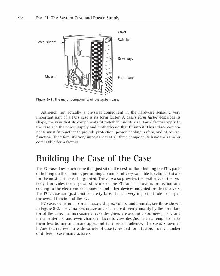
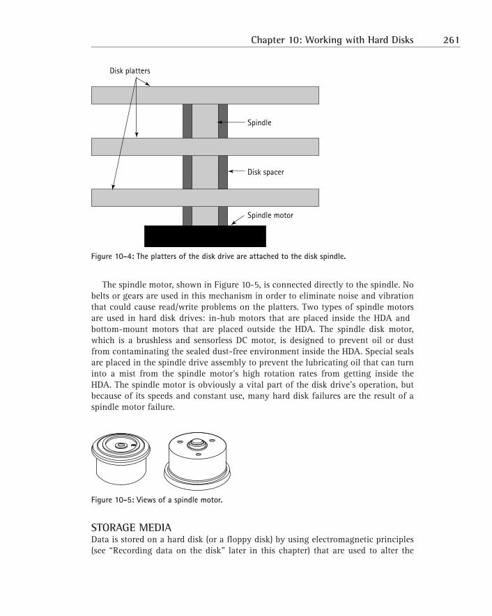
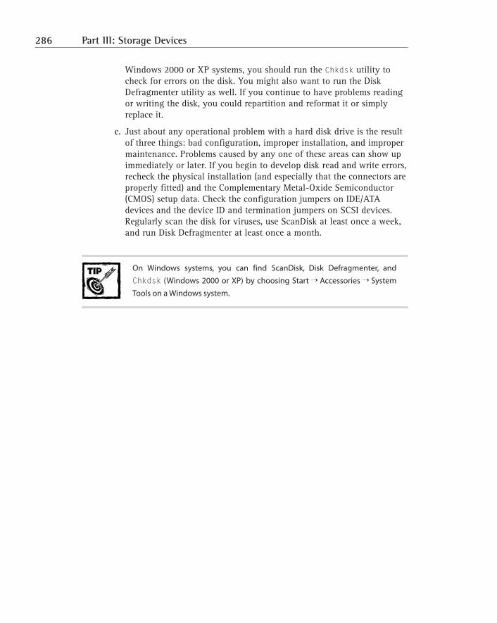
Dissecting the System CaseThe six major components of the case are shown in Figure 8-1. These components,which I cover in depth in this chapter, are
� Power supply
� Cover
� Chassis
� Front panel
� Switches
� Drive bays
191
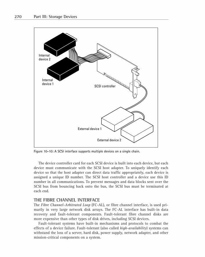
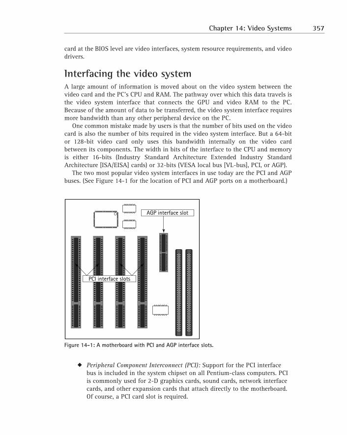
Figure 8-1: The major components of the system case.
Although not actually a physical component in the hardware sense, a veryimportant part of a PC’s case is its form factor. A case’s form factor describes itsshape, the way that its components fit together, and its size. Form factors apply tothe case and the power supply and motherboard that fit into it. These three compo-nents must fit together to provide protection, power, cooling, safety, and of course,function. Therefore, it’s very important that all three components have the same orcompatible form factors.
Building the Case of the CaseThe PC case does much more than just sit on the desk or floor holding the PC’s partsor holding up the monitor, performing a number of very valuable functions that arefor the most part taken for granted. The case also provides the aesthetics of the sys-tem; it provides the physical structure of the PC; and it provides protection andcooling to the electronic components and other devices mounted inside its covers.The PC’s case isn’t just another pretty face; it has a very important role to play inthe overall function of the PC.
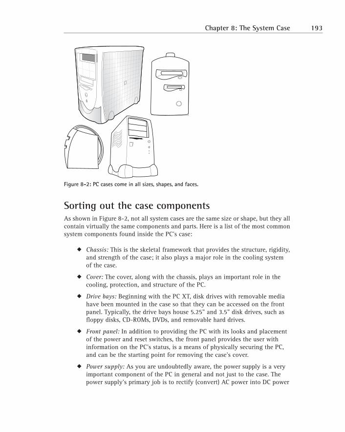
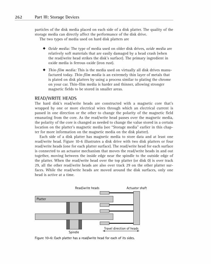
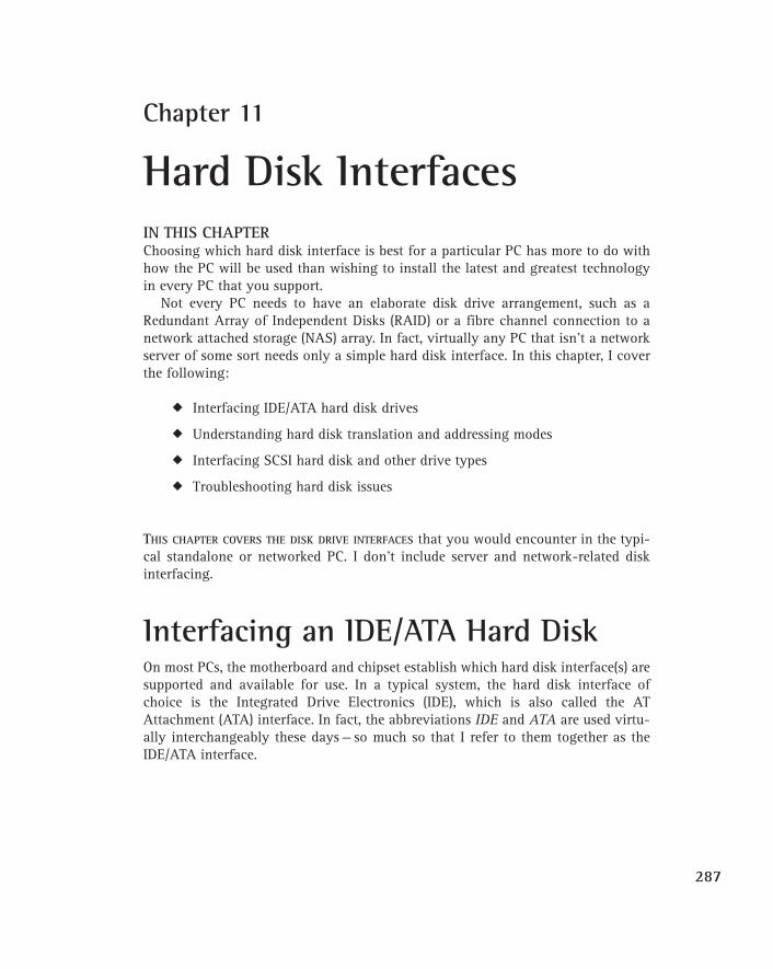
PC cases come in all sorts of sizes, shapes, colors, and animals, see those shownin Figure 8-2. The variances in size and shape are driven primarily by the form fac-tor of the case, but increasingly, case designers are adding color, new plastic andmetal materials, and even character faces to case designs in an attempt to makethem less boring and more appealing to a wider audience. The cases shown inFigure 8-2 represent a wide variety of case types and form factors from a numberof different case manufacturers.
Power supply
Chassis
Drive bays
Front panel
Cover
Switches
192 Part II: The System Case and Power Supply
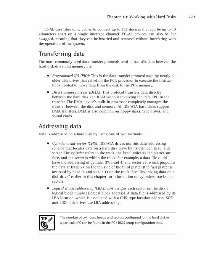
Figure 8-2: PC cases come in all sizes, shapes, and faces.
Sorting out the case componentsAs shown in Figure 8-2, not all system cases are the same size or shape, but they allcontain virtually the same components and parts. Here is a list of the most commonsystem components found inside the PC’s case:
� Chassis: This is the skeletal framework that provides the structure, rigidity,and strength of the case; it also plays a major role in the cooling systemof the case.
� Cover: The cover, along with the chassis, plays an important role in thecooling, protection, and structure of the PC.
� Drive bays: Beginning with the PC XT, disk drives with removable mediahave been mounted in the case so that they can be accessed on the frontpanel. Typically, the drive bays house 5.25" and 3.5" disk drives, such asfloppy disks, CD-ROMs, DVDs, and removable hard drives.
� Front panel: In addition to providing the PC with its looks and placementof the power and reset switches, the front panel provides the user withinformation on the PC’s status, is a means of physically securing the PC,and can be the starting point for removing the case’s cover.
� Power supply: As you are undoubtedly aware, the power supply is a veryimportant component of the PC in general and not just to the case. Thepower supply’s primary job is to rectify (convert) AC power into DC power
Chapter 8: The System Case 193
for use by the PC’s internal electronics. However, it also houses and pow-ers the main system cooling fan. Power supplies are not discussed in detailin this chapter other than to discuss how they fit in a case and their formfactors. See Chapter 9 for more specific information on the power supply.
� Switches: Most newer systems have their two main switches (the powerswitch and the reset switch) on the front panel. If the power switch is noton the front panel, it’s probably located either in the right-rear corner ornear a corner on the back of the PC.
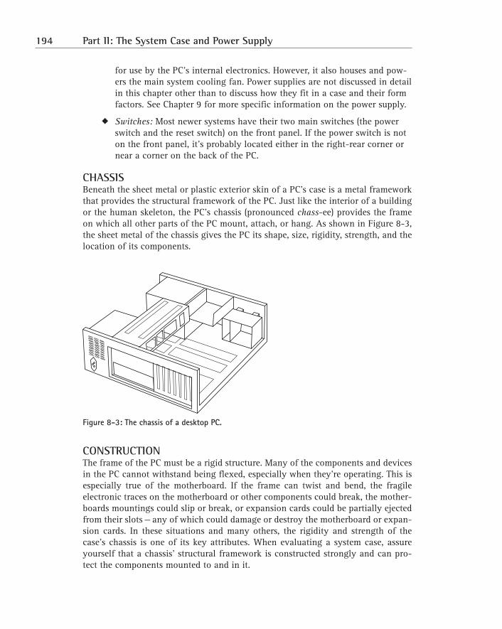
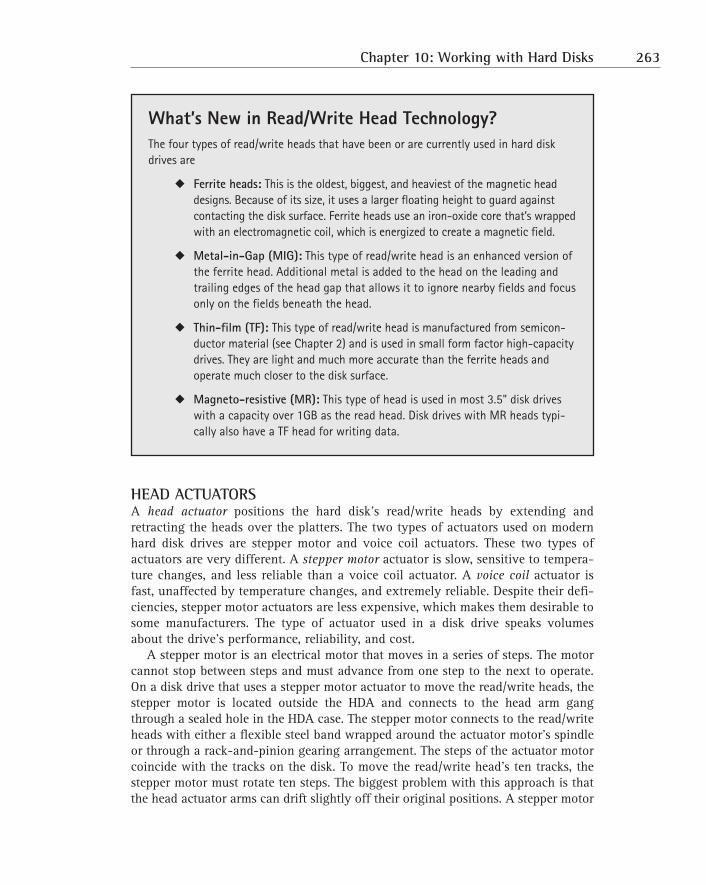
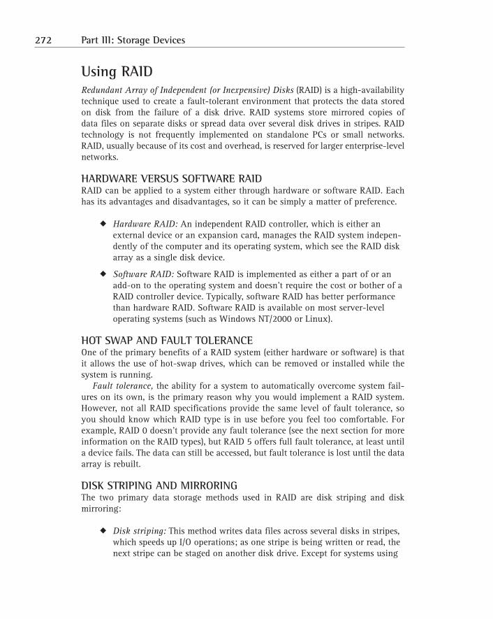
CHASSISBeneath the sheet metal or plastic exterior skin of a PC’s case is a metal frameworkthat provides the structural framework of the PC. Just like the interior of a buildingor the human skeleton, the PC’s chassis (pronounced chass-ee) provides the frameon which all other parts of the PC mount, attach, or hang. As shown in Figure 8-3,the sheet metal of the chassis gives the PC its shape, size, rigidity, strength, and thelocation of its components.
Figure 8-3: The chassis of a desktop PC.
CONSTRUCTIONThe frame of the PC must be a rigid structure. Many of the components and devicesin the PC cannot withstand being flexed, especially when they’re operating. This isespecially true of the motherboard. If the frame can twist and bend, the fragileelectronic traces on the motherboard or other components could break, the mother-boards mountings could slip or break, or expansion cards could be partially ejectedfrom their slots — any of which could damage or destroy the motherboard or expan-sion cards. In these situations and many others, the rigidity and strength of thecase’s chassis is one of its key attributes. When evaluating a system case, assureyourself that a chassis’ structural framework is constructed strongly and can pro-tect the components mounted to and in it.
194 Part II: The System Case and Power Supply
Not that you would usually know, but the frame of the PC chassis should be con-structed from a heavy-gauge steel that’s at least 18-gauge steel; 16-gauge steel iseven better. Less-expensive cases might use lighter-gauge steel or aluminum.Nothing is wrong with a lighter metal or aluminum case, provided that the case isreinforced in key supporting locations with heavier-gauge steel. Be wary of bargaincases made of lightweight aluminum because these cases are much too pliable andcan flex too much when being moved or lifted, causing the problems listed earlier.
The few pounds of the PC’s total weight that you save by buying a lighter-
weight case made of lighter-gauge metals are definitely not worth the
potential for problems that a flexing or bending case can cause.
Something more to consider when choosing a case for a PC is its internal designand layout. Where the crossbeams are located in relationship to where the mother-board, power supply, disk drives, and other components mount can pose problemslater when you’re trying to repair or upgrade the PC.
COVEROf the many ways to attach the cover to the chassis, the most common method is touse a few screws, but you’ll also see screwless or tool-less systems where the casecovers literally hang on the chassis by using keyholes or slide-and-lock features.However the cover attaches to the chassis, it’s extremely important that it has asnug and secure fit.
The case’s cover is engineered to provide the best possible airflow dynamics. It isalso a key component of the radio frequency interference (RFI) and electromagneticinterference (EMI) protection designed into the system. If your PC is by the FederalCommunications Commission (FCC) (and virtually all PCs are), the case wasdesigned to be a major part of the radio frequency (RF) emissions control of the PC.One of the risks in having a cover that doesn’t fit tightly and securely without gapsor loose parts is that it can emit RF signals and thus affect other devices near it.Sometimes, though, the problem with loose or badly fitting case parts can just bean annoying rattle from the escaping airflow breeze.
Many methods are used to attach the outer cover of the PC to the chassis. Themost common is that the cover is attached with screws to the front, sides, and rearof the chassis. Rarely would you completely remove all sections of the PC’s coverfrom the chassis. Normally, only the side (tower) or top (desktop) is removed to pro-vide access inside the case. The following sections discuss the more common stylesof covers and how they are attached and removed from the chassis.
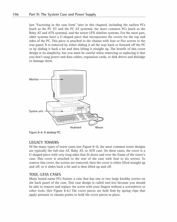
LEGACY DESKTOPSThe desktop PC, an example of which is shown in Figure 8-4, is by far the mostcommon of the case designs. There are desktop models for nearly every form factor
Chapter 8: The System Case 195
(see “Factoring in the case form” later in this chapter), including the earliest PCs(such as the PC XT and the PC AT systems), the more common PCs (such as theBaby AT and ATX systems), and the newer LPX slimline systems. For the most part,older systems have a U-shaped piece that incorporates the covers for the top andsides of the PC. This piece is attached to the chassis with four or five screws to therear panel. It is removed by either sliding it all the way back or forward off the PCor by sliding it back a bit and then lifting it straight up. The benefit of this coverdesign is its simplicity, but you must be careful when removing or replacing it thatyou don’t snag power and data cables, expansion cards, or disk drives and dislodgeor damage them.
Figure 8-4: A desktop PC.
LEGACY TOWERSOf the many types of tower cases (see Figure 8-5), the most common tower designsare typically the full-size AT, Baby AT, or ATX case. On these cases, the cover is aU-shaped piece with very long sides that fit down and over the frame of the tower’scase. This cover is attached to the rear of the case with four to six screws. Toremove this cover, the screws are removed; then the cover is either lifted straight upand off, or it slides back a bit and is then lifted up and off.
TOOL-LESS CASESMany brand-name PCs feature a case that has one or two large knobby screws onthe back panel of the case. This case design is called tool-less because you shouldbe able to remove and replace the screw with your fingers without a screwdriver orother tools. (See Figure 8-6.) The cover pieces are held firm by spring clips thatapply pressure to chassis points to hold the cover pieces in place.
Monitor
System unit
Keyboard Mouse
196 Part II: The System Case and Power Supply
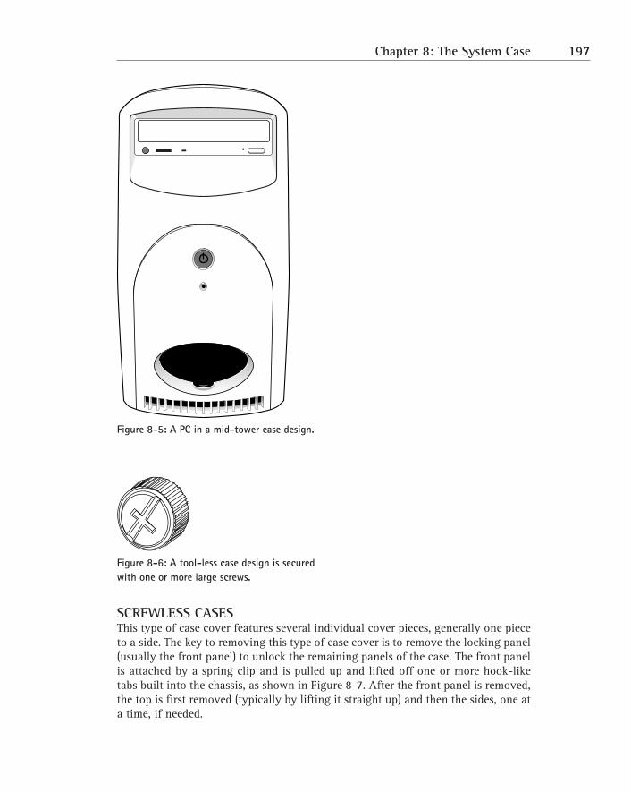
Figure 8-5: A PC in a mid-tower case design.
Figure 8-6: A tool-less case design is secured with one or more large screws.
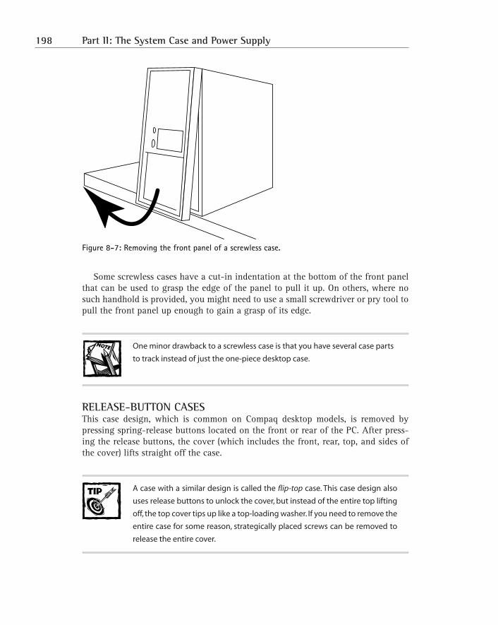
SCREWLESS CASESThis type of case cover features several individual cover pieces, generally one pieceto a side. The key to removing this type of case cover is to remove the locking panel(usually the front panel) to unlock the remaining panels of the case. The front panelis attached by a spring clip and is pulled up and lifted off one or more hook-liketabs built into the chassis, as shown in Figure 8-7. After the front panel is removed,the top is first removed (typically by lifting it straight up) and then the sides, one ata time, if needed.
Chapter 8: The System Case 197
Figure 8-7: Removing the front panel of a screwless case.
Some screwless cases have a cut-in indentation at the bottom of the front panelthat can be used to grasp the edge of the panel to pull it up. On others, where nosuch handhold is provided, you might need to use a small screwdriver or pry tool topull the front panel up enough to gain a grasp of its edge.
One minor drawback to a screwless case is that you have several case parts
to track instead of just the one-piece desktop case.
RELEASE-BUTTON CASESThis case design, which is common on Compaq desktop models, is removed bypressing spring-release buttons located on the front or rear of the PC. After press-ing the release buttons, the cover (which includes the front, rear, top, and sides ofthe cover) lifts straight off the case.
A case with a similar design is called the flip-top case. This case design also
uses release buttons to unlock the cover, but instead of the entire top lifting
off, the top cover tips up like a top-loading washer. If you need to remove the
entire case for some reason, strategically placed screws can be removed to
release the entire cover.
198 Part II: The System Case and Power Supply
FRONT-SCREW CASESOn this case design, the screws that hold the cover on the PC are located on thefront panel and are usually hidden behind sliding tabs or a snap-on panel.Removing the screws (and possibly some on the rear panel as well) allows the caseto be pulled forward and off the case.
Scanning the front panelThe primary purpose of the front panel (or bezel) is to cover up the front end of thechassis, but because it’s the part that the user looks at most of the time, efforts havebeen made to make it useful and appealing.
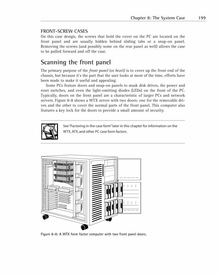
Some PCs feature doors and snap-on panels to mask disk drives, the power andreset switches, and even the light-emitting diodes (LEDs) on the front of the PC.Typically, doors on the front panel are a characteristic of larger PCs and networkservers. Figure 8-8 shows a WTX server with two doors: one for the removable dri-ves and the other to cover the normal parts of the front panel. This computer alsofeatures a key lock for the doors to provide a small amount of security.
See “Factoring in the case form” later in this chapter for information on the
WTX, ATX, and other PC case form factors.
Figure 8-8: A WTX form factor computer with two front panel doors.
Chapter 8: The System Case 199
STATUS LEDSMost PCs have LEDs on the front panel to show the status and activity of certainparts of the system. Typically, two LEDs are used: one that is lighted when thepower is on, and one that indicates when the hard disk is being accessed. OtherLEDs are visible on the front of the PC, but they are generally part of the disk driveinstalled in a drive bay. Very old PCs also have a Turbo LED that indicates that thesystem is in Turbo mode, which raises the processor speed of a PC. Turbo systemsare generally obsolete now.
Here is a quick overview of the front panel’s LEDs:
� Hard drive LED: When the disk drive is seeking, reading, or writing data,this red, orange, or amber LED is lighted and flashes. The speed with whichthe hard drive LED flashes is a good indicator of how busy your PC is.Typically, this LED is wired to the motherboard or the disk controller oradapter, which means that it reflects the activity of all disk drives on the PC.
� Power LED: This LED is typically green in color and is illuminated whenthe PC’s power is on.
� Turbo LED: If present, this yellow LED indicates that the PC is in Turbomode. The Turbo button was used on very early systems as a part of abackward compatibility strategy. There wasn’t a lot of software availableto begin with, and when the 8 MHz systems were released, many peoplehad a fair investment in software that would run only in the older 4.77MHz, or PC XT mode. Normal mode on these systems, 286 and 386processors, was Turbo mode. However, when the Turbo button wasreleased, two things happened: The PC processor was slowed to 4.77 MHz,and the Turbo LED was turned off.
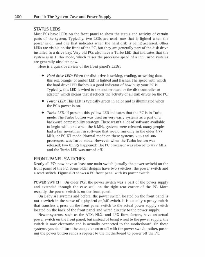
FRONT-PANEL SWITCHESNearly all PCs now have at least one main switch (usually the power switch) on thefront panel of the PC. Some older designs have two switches: the power switch anda reset switch. Figure 8-9 shows a PC front panel with its power switch.
POWER SWITCH On older PCs, the power switch was a part of the power supplyand extended through the case wall on the right-rear corner of the PC. Morerecently, the power switch is on the front panel.
On Baby AT systems and before, the power switch located on the front panel isnot a switch in the sense of a physical on/off switch. It is actually a proxy switchthat transfers a press on the front panel switch to the actual power supply switchlocated on the back of the front panel and wired directly to the power supply.
Newer systems, such as the ATX, NLX, and LPX form factors, have an actualpower switch on the front panel, but instead of being wired to the power supply, theswitch is now electronic and is actually connected to the motherboard. On thesesystems, you don’t turn the computer on or off with the power switch; rather, push-ing the power button sends a request to the motherboard to power off the PC.
200 Part II: The System Case and Power Supply
Figure 8-9: The power switch on a PC’s front panel.
RESET BUTTON Although disappearing from PCs largely to prevent accidentalresets, the reset switch, also referred to as the reset button, performs a hardwarereset when pressed. This provides the user with a means of restarting the PC shouldit halt and not respond to normal shutdown or restart commands. Using the resetbutton is better than powering the PC off and back on, which can sometimes resultin POST or BIOS errors.
On some older PCs, the reset button was placed on the front panel and was easilyaccessed, which caused more than one unexpected system reset. Newer cases, ifthey feature a reset button, recess the button to prevent inadvertent resets fromtaking place. A few manufacturers have moved the reset button to the back of thePC, which is safer yet.
Some manufacturers, such as Gateway, don’t include a reset button on theirsystems. Resetting the PC must be done via the keyboard (by pressing Ctrl+Alt+Del)or by using the operating system’s restart process.
TURBO BUTTON As I explain in the earlier section “Status LEDs,” the Turbo but-ton and its functions are now obsolete except on 286 and early 386 computers. Ifyour front panel has a Turbo button, chances are that it’s not connected to any-thing; to avoid any possible problems, you should never press it.
KEYLOCKSAlthough not technically a switch, some cases have keylocks on their front panels.The two types of keylocks available on PC front panels are a front panel door lockand a keyboard lockout.
� Front panel door lock: If the front panel of your PC has one or moredoors, it might also have a door lock either on the door or on the frontpanel. When the doors are closed and locked, curiosity seekers are pre-vented from accessing the drives behind the doors. However, because the
Chapter 8: The System Case 201
doors are made of plastic and can be pried open easily, this feature shouldnot be used or thought of as a means to secure the system.
� Keyboard lockout: When locked, this type of keylock sets a logical condi-tion on the system that locks out the keyboard, thus preventing anyonefrom using the PC. When someone attempts to use the PC while this key-lock is locked, an error message is displayed on the monitor that in effectsays that the system is not available for use. While this keylock is locked,the PC will not boot. The keyboard lockout keylock was intended to be afirst-level of security for PCs in large offices and work areas. The keys fora PC keylock are usually round, and many manufacturers use the samekey for all their systems. Thus, the security that keylocks can provide islimited. Anyone with a screwdriver can open the case and disable thelock; and on some cases, you don’t even need the screwdriver.
If your case has a keylock or a front-panel door lock, be sure that it also has
keylock keys. Typically, you’ll get two of each key. If you plan to use them,
store one of the keys in a safe place so that if you lose the first one, you can
still unlock your PC.
DRIVE BAYSSince the PC AT, you have been able to decide the number and type of disk drivesin your computer. As long as the power supply and cooling system would supportthem, you could add floppy disk drives, hard disk drives, CD-ROM drives, tape dri-ves, and more to your PC.
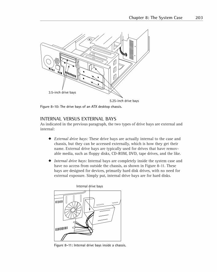
Generally, drives are installed in the drive bays provided on virtually all PC casedesigns and form factors. Figure 8-10 shows a desktop computer with its drive baysexposed. This system, an ATX case, provides three 5.25" half-height drive bays, two3.5" one-inch high drive bays, and two 3.5" drive bays hidden inside the case.
Originally, disk drives required a drive bay that was 3.5" in height. As technol-ogy was able to reduce the size of the overall drive, this height was cut in half, andnow most of the drive bays available for 5.25" devices are less than 2 inches inheight and are called half-height.
202 Part II: The System Case and Power Supply
Figure 8-10: The drive bays of an ATX desktop chassis.
INTERNAL VERSUS EXTERNAL BAYSAs indicated in the previous paragraph, the two types of drive bays are external andinternal:
� External drive bays: These drive bays are actually internal to the case andchassis, but they can be accessed externally, which is how they get theirname. External drive bays are typically used for drives that have remov-able media, such as floppy disks, CD-ROM, DVD, tape drives, and the like.
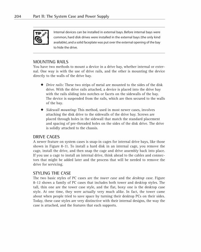
� Internal drive bays: Internal bays are completely inside the system case andhave no access from outside the chassis, as shown in Figure 8-11. Thesebays are designed for devices, primarily hard disk drives, with no need forexternal exposure. Simply put, internal drive bays are for hard disks.
Figure 8-11: Internal drive bays inside a chassis.
Internal drive bays
5.25-inch drive bays
3.5-inch drive bays
Chapter 8: The System Case 203
Internal devices can be installed in external bays. Before internal bays were
common, hard disk drives were installed in the external bays (the only kind
available), and a solid faceplate was put over the external opening of the bay
to hide the drive.
MOUNTING RAILSYou have two methods to mount a device in a drive bay, whether internal or exter-nal. One way is with the use of drive rails, and the other is mounting the devicedirectly to the walls of the drive bay.
� Drive rails: These two strips of metal are mounted to the sides of the diskdrive. With the drive rails attached, a device is placed into the drive baywith the rails sliding into notches or facets on the sidewalls of the bay.The device is suspended from the rails, which are then secured to the wallsof the bay.
� Sidewall mounting: This method, used in most newer cases, involvesattaching the disk drive to the sidewalls of the drive bay. Screws areplaced through holes in the sidewall that match the standard placementand spacing of pre-threaded holes on the sides of the disk drive. The driveis solidly attached to the chassis.
DRIVE CAGESA newer feature on system cases is snap-in cages for internal drive bays, like thoseshown in Figure 8-11. To install a hard disk in an internal cage, you remove thecage, install the drive, and then snap the cage and drive assembly back into place.If you use a cage to install an internal drive, think ahead to the cables and connec-tors that might be added later and the process that will be needed to remove thedrive for servicing.
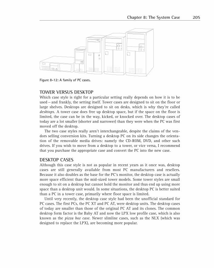
STYLING THE CASEThe two basic styles of PC cases are the tower case and the desktop case. Figure8-12 shows a family of PC cases that includes both tower and desktop styles. Thetall, thin one are the tower case style, and the flat, boxy one is the desktop casestyle. At one time, they were actually very much alike. In fact, the tower cameabout when people tried to save space by turning their desktop PCs on their sides.Today, these case styles are very distinctive with their internal designs, the way thecase is attached, and the features that each supports.
204 Part II: The System Case and Power Supply
Figure 8-12: A family of PC cases.
TOWER VERSUS DESKTOPWhich case style is right for a particular setting really depends on how it is to beused — and frankly, the setting itself. Tower cases are designed to sit on the floor orlarge shelves. Desktops are designed to sit on desks, which is why they’re calleddesktops. A tower case does free up desktop space, but if the space on the floor islimited, the case can be in the way, kicked, or knocked over. The desktop cases oftoday are a lot smaller (shorter and narrower) than they were when the PC was firstmoved off the desktop.
The two case styles really aren’t interchangeable, despite the claims of the ven-dors selling conversion kits. Turning a desktop PC on its side changes the orienta-tion of the removable media drives: namely the CD-ROM, DVD, and other suchdrives. If you wish to move from a desktop to a tower, or vice versa, I recommendthat you purchase the appropriate case and convert the PC into the new case.
DESKTOP CASESAlthough this case style is not as popular in recent years as it once was, desktopcases are still generally available from most PC manufacturers and resellers.Because it also doubles as the base for the PC’s monitor, the desktop case is actuallymore space efficient than the mid-sized tower models. Some tower styles are smallenough to sit on a desktop but cannot hold the monitor and thus end up using morespace than a desktop unit would. In some situations, the desktop PC is better suitedthan a PC in a tower case, primarily where floor space is limited.
Until very recently, the desktop case style had been the unofficial standard forPC cases. The first PCs, the PC XT and PC AT, were desktop units. The desktop casesof today are smaller than those of the original PC AT and its clones. The commondesktop form factor is the Baby AT and now the LPX low profile case, which is alsoknown as the pizza box case. Newer slimline cases, such as the NLX (which wasdesigned to replace the LPX), are becoming more popular.
Chapter 8: The System Case 205
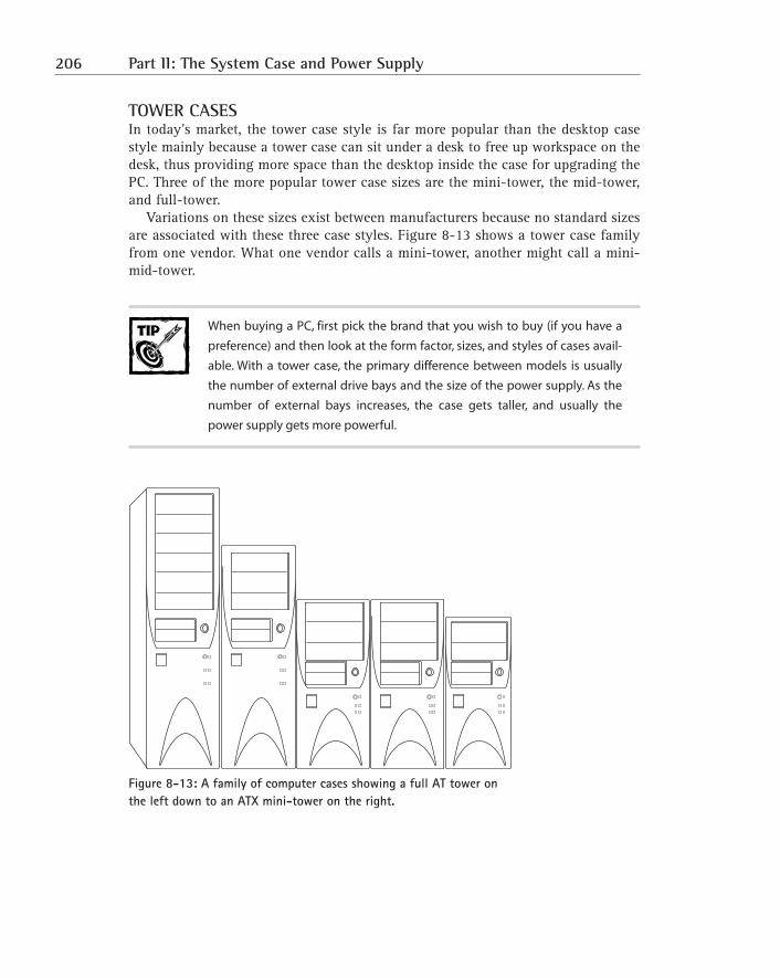
TOWER CASESIn today’s market, the tower case style is far more popular than the desktop casestyle mainly because a tower case can sit under a desk to free up workspace on thedesk, thus providing more space than the desktop inside the case for upgrading thePC. Three of the more popular tower case sizes are the mini-tower, the mid-tower,and full-tower.
Variations on these sizes exist between manufacturers because no standard sizesare associated with these three case styles. Figure 8-13 shows a tower case familyfrom one vendor. What one vendor calls a mini-tower, another might call a mini-mid-tower.
When buying a PC, first pick the brand that you wish to buy (if you have a
preference) and then look at the form factor, sizes, and styles of cases avail-
able. With a tower case, the primary difference between models is usually
the number of external drive bays and the size of the power supply. As the
number of external bays increases, the case gets taller, and usually the
power supply gets more powerful.
Figure 8-13: A family of computer cases showing a full AT tower on the left down to an ATX mini-tower on the right.
206 Part II: The System Case and Power Supply
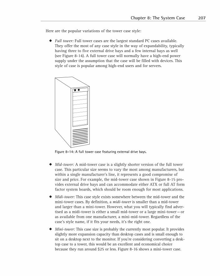
Here are the popular variations of the tower case style:
� Full tower: Full tower cases are the largest standard PC cases available.They offer the most of any case style in the way of expandability, typicallyhaving three to five external drive bays and a few internal bays as well(see Figure 8-14). A full tower case will normally have a high-end powersupply under the assumption that the case will be filled with devices. Thisstyle of case is popular among high-end users and for servers.
Figure 8-14: A full tower case featuring external drive bays.
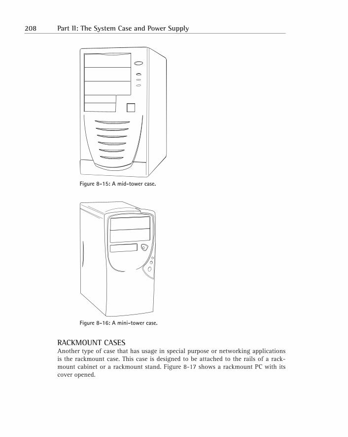
� Mid-tower: A mid-tower case is a slightly shorter version of the full towercase. This particular size seems to vary the most among manufacturers, butwithin a single manufacturer’s line, it represents a good compromise ofsize and price. For example, the mid-tower case shown in Figure 8-15 pro-vides external drive bays and can accommodate either ATX or full AT formfactor system boards, which should be room enough for most applications.
� Midi-tower: This case style exists somewhere between the mid-tower and themini-tower cases. By definition, a midi-tower is smaller than a mid-towerand larger than a mini-tower. However, what you will typically find adver-tised as a midi-tower is either a small mid-tower or a large mini-tower — oras available from one manufacturer, a mini-mid-tower. Regardless of thecase’s style name, if it fits your needs, it’s the right one.
� Mini-tower: This case size is probably the currently most popular. It providesslightly more expansion capacity than desktop cases and is small enough tosit on a desktop next to the monitor. If you’re considering converting a desk-top case to a tower, this would be an excellent and economical choicebecause they run around $25 or less. Figure 8-16 shows a mini-tower case.
Chapter 8: The System Case 207
Figure 8-15: A mid-tower case.
Figure 8-16: A mini-tower case.
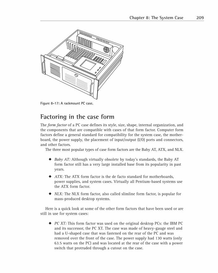
RACKMOUNT CASESAnother type of case that has usage in special purpose or networking applicationsis the rackmount case. This case is designed to be attached to the rails of a rack-mount cabinet or a rackmount stand. Figure 8-17 shows a rackmount PC with itscover opened.
208 Part II: The System Case and Power Supply
Figure 8-17: A rackmount PC case.
Factoring in the case formThe form factor of a PC case defines its style, size, shape, internal organization, andthe components that are compatible with cases of that form factor. Computer formfactors define a general standard for compatibility for the system case, the mother-board, the power supply, the placement of input/output (I/O) ports and connectors,and other factors.
The three most popular types of case form factors are the Baby AT, ATX, and NLX.
� Baby AT: Although virtually obsolete by today’s standards, the Baby ATform factor still has a very large installed base from its popularity in pastyears.
� ATX: The ATX form factor is the de facto standard for motherboards,power supplies, and system cases. Virtually all Pentium-based systems usethe ATX form factor.
� NLX: The NLX form factor, also called slimline form factor, is popular formass-produced desktop systems.
Here is a quick look at some of the other form factors that have been used or arestill in use for system cases:
� PC XT: This form factor was used on the original desktop PCs: the IBM PCand its successor, the PC XT. The case was made of heavy-gauge steel andhad a U-shaped case that was fastened on the rear of the PC and wasremoved over the front of the case. The power supply had 130 watts (only63.5 watts on the PC) and was located at the rear of the case with a powerswitch that protruded through a cutout on the case.
Chapter 8: The System Case 209
� AT: The IBM PC AT, although not much different on the outside than itspredecessors, was quite different on the inside. The motherboard andpower supply (which was much larger) were repositioned inside the case.The AT quickly became the standard form factor among manufacturers;all subsequent form factors, whether desktop or tower, are based in oneway or another on the AT.
� LPX: Although never officially accepted as a standard form factor, LPX isthe oldest of the low-profile form factors. Over the past ten years, it hasbeen one of the most popular slimline form factors sold. Slimline cases area little shorter than Baby AT or ATX cases. This is achieved by movingexpansion cards to a riser board that mounts horizontally in the caseinstead of vertically, thereby saving inches of height.
� MicroATX and FlexATX: These two ATX-based form factors define speci-fications for smaller versions of the ATX motherboard. Micro-ATX andFlexATX do not define case form factors, but manufacturers are designingcases to take advantage of their smaller footprint. These form factors areintended for PCs targeted to the mass market and home users.
� WTX: The W stands for workstation, and the WTX is a form factorintended for high-performance workstations and servers. This form factordefines a modular case that features a motherboard that’s twice the size ofan ATX motherboard. A WTX case features space for high-capacity,redundant power supplies, removable panels for easy access to compo-nents, a large number of hard drive bays, and support for multiple coolingfans. Refer to Figure 8-8 for a WTX form factor computer.
For more information on PC form factors as they relate to motherboards
and power supplies, see Chapters 1 and 9.
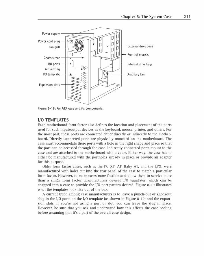
SYSTEM CASE FEATURESWhen you buy a system case, like the one shown in Figure 8-18 without its covers,it will include some pre-installed components and features, which are usually theoptional pieces that conform a generic case to fit a particular form factor and yourparticular requirements. Because several of the form factors are very close in theirsize and component placement, manufacturers make cases that can be used with anumber of form factors. Applying such items as an I/O template, the appropriatepower supply, and motherboard mounts turns the generic case into a custom casethat’s just right for your needs.
210 Part II: The System Case and Power Supply
Figure 8-18: An ATX case and its components.
I/O TEMPLATESEach motherboard form factor also defines the location and placement of the portsused for such input/output devices as the keyboard, mouse, printer, and others. Forthe most part, these ports are connected either directly or indirectly to the mother-board. Directly connected ports are physically mounted on the motherboard. Thecase must accommodate these ports with a hole in the right shape and place so thatthe port can be accessed through the case. Indirectly connected ports mount to thecase and are attached to the motherboard with a cable. Either way, the case has toeither be manufactured with the portholes already in place or provide an adapterfor this purpose.
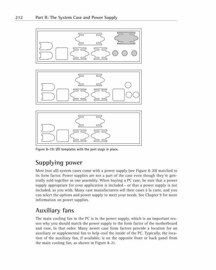
Older form factor cases, such as the PC XT, AT, Baby AT, and the LPX, weremanufactured with holes cut into the rear panel of the case to match a particularform factor. However, to make cases more flexible and allow them to service morethan a single form factor, manufacturers devised I/O templates, which can besnapped into a case to provide the I/O port pattern desired. Figure 8-19 illustrateswhat the templates look like out of the box.
A current trend among case manufacturers is to leave a punch-out or knockoutslug in the I/O ports on the I/O template (as shown in Figure 8-19) and the expan-sion slots. If you’re not using a port or slot, you can leave the slug in place.However, be sure that you ask and understand how this affects the case coolingbefore assuming that it’s a part of the overall case design.
Power supply
Power cord plug
Fan grill
Chassis rear
External drive bays
Front of chassis
Internal drive bays
Auxiliary fan
I/O ports
Air venting
I/O template
Expansion slots
Chapter 8: The System Case 211
Figure 8-19: I/O templates with the port slugs in place.
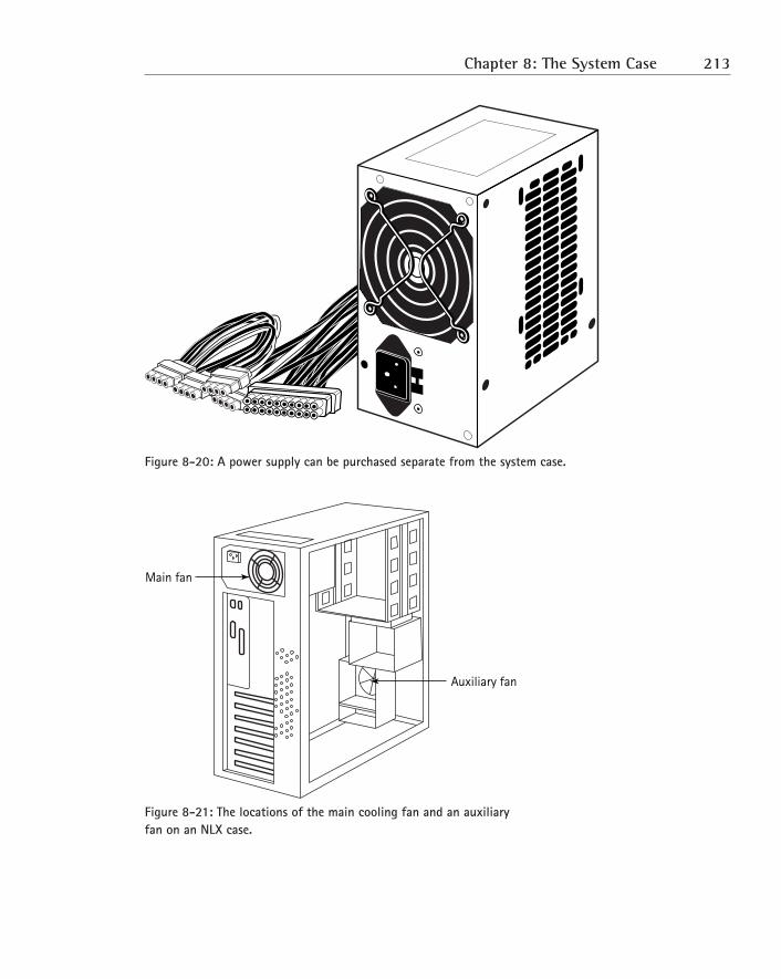
Supplying powerMost (not all) system cases come with a power supply (see Figure 8-20) matched toits form factor. Power supplies are not a part of the case even though they’re gen-erally sold together as one assembly. When buying a PC case, be sure that a powersupply appropriate for your application is included — or that a power supply is notincluded, as you wish. Many case manufacturers sell their cases à la carte, and youcan select the options and power supply to meet your needs. See Chapter 9 for moreinformation on power supplies.
Auxiliary fansThe main cooling fan in the PC is in the power supply, which is an important rea-son why you should match the power supply to the form factor of the motherboardand case, in that order. Many newer case form factors provide a location for anauxiliary or supplemental fan to help cool the inside of the PC. Typically, the loca-tion of the auxiliary fan, if available, is on the opposite front or back panel fromthe main cooling fan, as shown in Figure 8-21.
212 Part II: The System Case and Power Supply
Figure 8-20: A power supply can be purchased separate from the system case.
Figure 8-21: The locations of the main cooling fan and an auxiliary fan on an NLX case.
Main fan
Auxiliary fan
Chapter 8: The System Case 213
Lights, sound, and the connecting wiresThe other components of a PC case are the LEDs, the system speaker, and the wiringthat connects these two items, plus a few more, to the power supply and motherboard.
� LEDs: Most PC cases include at least two LEDs that are used as indicatorsfor the power and hard disk. Although fairly uncommon today, somecases might have other LEDs for Turbo mode and the CPU’s activity level.
� Front panel wiring: On the back of the front panel (near the systemspeaker, the LEDs, and the keylock) should be a small bundle of multi-colored wires that connect these items to the motherboard and perhapseach other. The LEDs should have two wires: one that’s either black orwhite (ground) and one that’s some other color (positive).
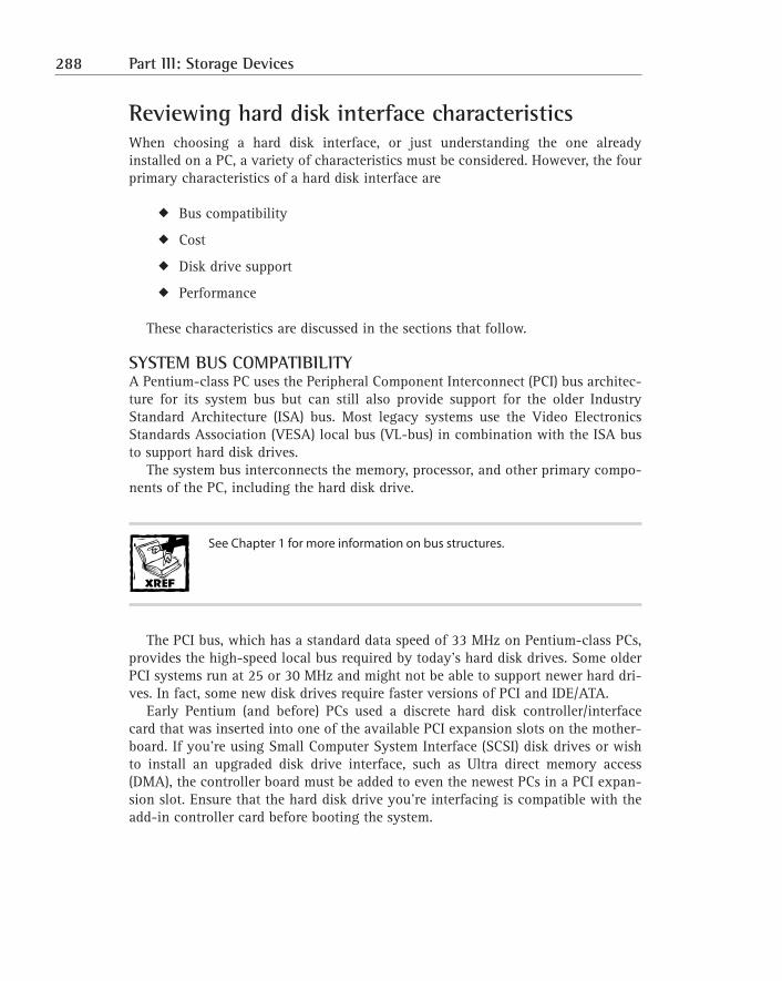
� System speaker: The system speaker isn’t intended for stereo sound or toplay your audio CDs. Rather, it’s only meant to be a basic means of com-munication between the motherboard, BIOS, chipset, processor, and othersystem components and the user. About the best it can do is sound beepcodes during the boot and other monotone sounds by some applicationsoftware. The system speaker is normally mounted inside the case near oron the front panel. On a new case, it might be included loose (not pre-mounted), allowing you to place it where you wish.
Cooling ventsAlthough this might seem obvious, air must have a means to get into or out of thesystem case. Usually, the case should have a grouping of small vent holes, cuts, lou-vers, or the like. Because of its larger airflow, a bigger case cools the internal com-ponents better than a smaller case, but both must still have a way to vent the case.You can assume that any case you buy from a reputable manufacturer is engineeredproperly for cooling and ventilation.
When assembling a system case and its components, be aware of where the
vents are and take care not to block them.
214 Part II: The System Case and Power Supply
Mounting the motherboardIf you’re buying a new case, it should come with mounting hardware. These piecesnormally come with the case and not the motherboard. Make sure that you have theappropriate mounting hardware, or your PC building project will come to a halt!The exact hardware included varies greatly and depends on what the manufacturerdecided to include in the case, but you’ll generally find some combination of thefollowing:
� Fixed mounting hardware: Some cases already have their mounting hard-ware fixed (meaning soldered or welded) in place to match the mountingholes of a motherboard of the same form factor as the case. This isintended to save you time, but if you ever want to move to another formfactor motherboard, you’ll need a new case.
� Metal standoffs: Metal standoffs are rarely used because they’re a botherto work with and they cost more than the plastic type. However, if yourcase has threaded holes in place of mounting slots, these brass hexagonspacers need to be used. The standoff has screw threads on one end and athreaded screw hole on the other end. The screw end is screwed into thecase, and then the motherboard (along with some insulating Teflon,Delran, or paper washers) is attached to the other end with a screw. Thewashers are placed between the standoff and the motherboard andbetween the motherboard and the screw. This keeps the metal-edgedmounting hole from contacting the screw and standoff and preventing itfrom shorting the board.
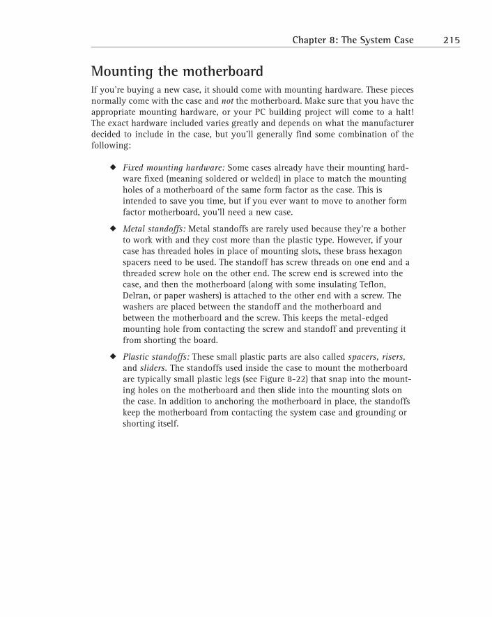
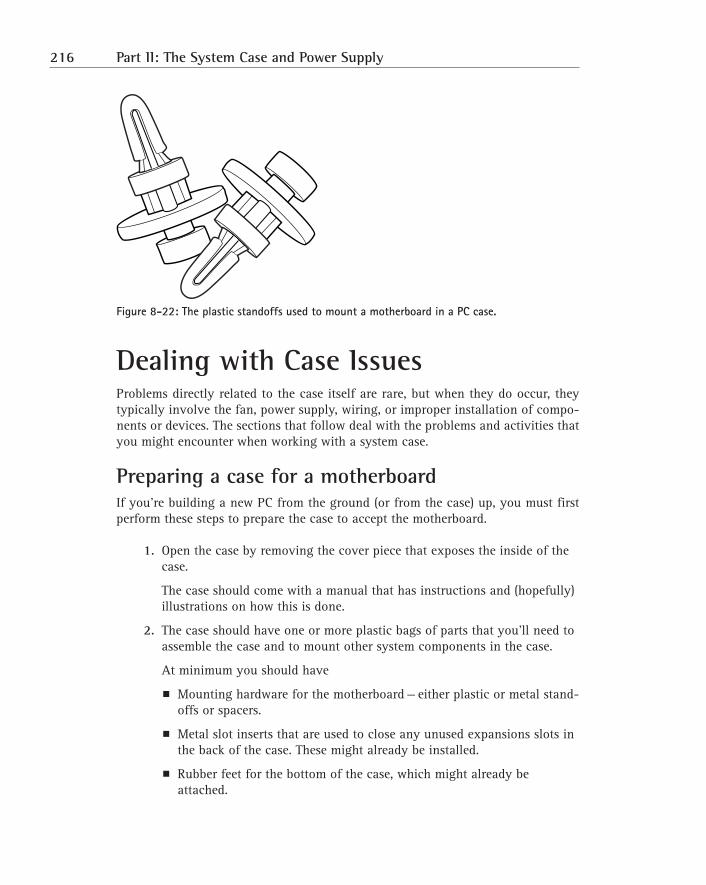
� Plastic standoffs: These small plastic parts are also called spacers, risers,and sliders. The standoffs used inside the case to mount the motherboardare typically small plastic legs (see Figure 8-22) that snap into the mount-ing holes on the motherboard and then slide into the mounting slots onthe case. In addition to anchoring the motherboard in place, the standoffskeep the motherboard from contacting the system case and grounding orshorting itself.
Chapter 8: The System Case 215
Figure 8-22: The plastic standoffs used to mount a motherboard in a PC case.
Dealing with Case IssuesProblems directly related to the case itself are rare, but when they do occur, theytypically involve the fan, power supply, wiring, or improper installation of compo-nents or devices. The sections that follow deal with the problems and activities thatyou might encounter when working with a system case.
Preparing a case for a motherboardIf you’re building a new PC from the ground (or from the case) up, you must firstperform these steps to prepare the case to accept the motherboard.
1. Open the case by removing the cover piece that exposes the inside of thecase.
The case should come with a manual that has instructions and (hopefully)illustrations on how this is done.
2. The case should have one or more plastic bags of parts that you’ll need toassemble the case and to mount other system components in the case.
At minimum you should have
� Mounting hardware for the motherboard — either plastic or metal stand-offs or spacers.
� Metal slot inserts that are used to close any unused expansions slots inthe back of the case. These might already be installed.
� Rubber feet for the bottom of the case, which might already beattached.
216 Part II: The System Case and Power Supply
� Drive cages (if the case supports them) or drive rails.
� A power supply AC cord, if a power supply is included with the case. Ifnot, you’ll need to install one before installing any other componentsto the case.
3. Use compressed air to blow out any packing materials or dust in a newcase.
4. Check the power supply for apparent damage, and then check the cables,fan, and its casing.
Make sure that the voltage selector is set appropriately for your powersource.
5. Install the feet, if they’re not already installed.
After the motherboard is installed, this step might not be as easy as it isnow.
6. Install the slot inserts into the expansion slots.
This step can wait until after the expansion slots are installed, if you prefer.
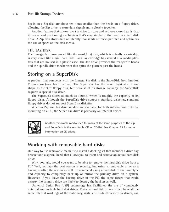
7. Install any auxiliary fans that you wish to use, if the case supports them.
8. If the case has a removable or swing out motherboard panel, remove it(see the case’s documentation) so that you can install the motherboard toit outside of the case.
The front panel LEDs don’t light upIf the front panel LEDs don’t light up, the problem is probably that the front panel’sLEDs aren’t connected or have been connected incorrectly. The good news aboutconnecting the front panel LEDs is that if you do it wrong, all that will happen isthat they won’t light up.
Front panel LEDs will have a ground wire. The ground wire is either a black orwhite wire attached to a one-pin push-on connector that’s connected to themotherboard’s LED ground connector, which should be marked on the mother-board. The positive wire is some other color (perhaps red, blue, or green) that’s con-nected to the motherboard’s LED connector. It, too, is a one-pin push-on connector.These connectors are usually located along the front or side edge of the mother-board. Check the motherboard’s documentation for the location of these connectorsif you cannot find them.
If the LEDs don’t light up, try reversing the wires of the bad LED or exchangingthe wires of two or more of the LEDS. Chances are that you’ll find a combinationthat works.
Chapter 8: The System Case 217
No sound is coming from the system speakerIf no sound is coming from the system speaker, the speaker has probably not beenconnected to the motherboard or the connectors are plugged in incorrectly.
Like the LED wires covered in the previous section, the system speaker has twowires that connect to the motherboard with either a single 4-pin connector or two1-pin connectors. If you get the connectors on backwards or off to one side or theother, the worst that can happen is that it just won’t work. You won’t damage thespeaker by connecting it incorrectly.
Also, the speaker could be defective. If the wiring looks right and checks against thedocumentation, try using the speaker in a new PC or using a new speaker in this PC.
The reset button does not restart the PCIf the PC has a reset button, it should restart the PC when pressed. If nothing hap-pens when you press this button, the wires that connect the reset button to themotherboard were probably not installed, were not installed properly, or have comeloose — or you have a problem with the motherboard that you might just have tolive with.
Check the motherboard’s documentation to verify the location of the connectorfor the reset button’s wiring and verify that it’s properly connected.
The power on/off button does not workIf the power on/off button doesn’t work, make sure you know which case, mother-board, and power supply form factors you have before you do very much to trou-bleshoot this problem. ATX form factor motherboards and power supplies pass liveAC through to the on/off switches that are on the front panel, and getting theseconnections wrong can be dangerous to the motherboard and yourself.
Follow the instructions in the motherboard’s documentation for connectingthese switches or that in the case’s documentation for the front-panel switches. AnATX power supply doesn’t have a front-panel cable and might not have an on/offswitch of its own. An ATX motherboard controls the power supply with a logic cir-cuit that turns it on and off. The switch on the front panel sends a signal to themotherboard, which relays it the power supply. The ATX motherboard always hasat least 5 volts of standby power on it, even when the power supply is off.
Setting the monitor on the system case halts the PCIf the PC freezes, reboots, or powers off whenever you set anything (especially themonitor) on top of the case, chances are that something is causing the motherboardto touch the case and short out, which should happen soon after the system boots,if it will boot. The weight of the monitor or other object is apparently too much forthe case’s structure, thus causing it to bend or flex.
218 Part II: The System Case and Power Supply
Here’s another possibility: In some weird way, the monitor (or whatever else youare putting on the case) is changing the airflow inside the system case and causingthe processor or motherboard to overheat. The processor and chipset will shut downwhen they approach operating temperatures outside their normal ranges.
Check to see that the monitor is sitting squarely in the center of the case or overthe main structural points of the case. Avoid setting the monitor off to one side oron a corner of the case.
Then try operating the system without the monitor on top of the case. If it worksfine, the case just isn’t strong enough to hold the monitor, especially if it’s a large17" monitor or larger. If workspace is an issue, several monitor stands are availablethat function like bridges placed over the PC’s system unit to hold up the monitor.You can also place the monitor on a swing arm mount that connects to the desk.
If the problem continues, investigate a cooling issue or perhaps a faulty powersupply. Try rearranging the cables inside the case to open up some airflow orperhaps, if the case supports it, add an auxiliary fan.
Chapter 8: The System Case 219
Chapter 9
Powering Up the PCIN THIS CHAPTERBecause a computer is an electrical device and digital logic circuits require a non-fluctuating direct current (DC), a switching power supply is used to convert analternating current (AC) power source to the DC power that it needs. The electroniccomponents of the PC, such as the processor and memory, require +3.3 volts (v) or+5v of DC power, and hard disk drives and other permanent storage devices need+12v DC.
To that end, this chapter includes information on the following:
� The physical construction and components of a PC power supply
� The electrical systems of a PC power supply
� Protecting the PC from external power problems
� Diagnosing and resolving common PC power supply issues
YOU DON’T HAVE TO BE AN ELECTRICIAN TO WORK ON COMPUTERS, but a good work-ing knowledge of PC electrical systems, and especially its power supply, can saveyou time and energy (no pun intended) when trying to chase down an intermittentproblem.
Understanding the Functions of thePower SupplyThe primary functions of a PC power supply are cooling, rectification, filtering, reg-ulation, isolation, power management, and voltage conversion. Here is an explana-tion of each of these functions:
� Cooling: The system fan, which controls the airflow through the systemcase, is located inside the power supply.
� Rectification: This function is directly involved with converting the ACpower of the power source to the DC power needed by the PC’s components.
� Filtering: Rectification usually introduces a ripple in the DC voltage,which filtering smoothes out. 221
� Regulation: Along with filtering, voltage regulation removes any line orload variations in the DC voltage produced by the power supply.
� Isolation: This separates the AC power supply from the converted, recti-fied, filtered, and regulated DC power.
� Power management: Most computers produced over the past few yearshave included energy-efficiency tools and power management functionsthat help reduce the amount of electrical power used by the PC.
� Voltage conversion: This function involves changing the 110v AC primarypower source into the +12v and +5v DC used by many older systems andthe +3.3v DC used by most newer computer. During the reign of the80486, +3.3v processors were introduced and used voltage regulators onthe motherboard to reduce the DC current to this level. However, powersupplies that now provide +3.3v DC are common.
In those areas of the world where the power source is already a direct cur-
rent, the power supply performs all the same tasks except rectification. Most
power supplies have the ability to take either a 110v AC input or a 220v DC
input and have a slide switch on the outside by the fan grill to select the
power source voltage to which it is attached.
Producing good powerIn addition to providing converted power to the motherboard and the other parts ofthe PC, the power supply sends a very important signal to the motherboard throughits umbilical connection — the POWER_GOOD (or Pwr_OK on an ATX form factorpower supply) signal.
Read more about form factors in Chapter 8.
When the PC is powered on, the power supply performs a self-test and checkswhether the required voltages (in and out) are correct. If so, the POWER_GOOD sig-nal line is set high (on) to indicate that the motherboard can rely on the powerbeing supplied. If the signal is not set, the processor’s timing chip (to which thissignal line is attached) sends the processor a reset command that starts the BasicInput/Output System’s (BIOS’) initialization code.
The effect of the POWER_GOOD signal not being set is that the PC is trapped ina loop continuously calling the BIOS. In this situation, the power supply appears to
222 Part II: The System Case and Power Supply
be working, and some power is being supplied to the PC and its peripherals. Thefront panel lights might be on, the disk drives spinning, and the power supply fanrunning, but the BIOS will never reach the Power-On Self-Test (POST) process andwill appear to be hung.
Turning power on and offOn ATX and NLX form factors and most of the other later form factors, the moth-erboard can turn the power supply on or off. This is done through the PS_ON(power supply on) signal that passes between the motherboard and the power sup-ply. If your PC powers off when Windows is finished shutting down, you have thisfeature.
Another indicator that your power supply supports PS_ON is the use of momentary-on or always-on power switches that are connected to the motherboardin place of an exterior switch connected to the power supply. When this signal lineis pulled to a low voltage signal, the +12v DC, +5v DC, +3.3v DC, –5v DC, and –12vDC power lines (see Figures 9-1 and 9-2) are turned on. When pulled to a high-voltage signal, or open-circuited, the DC output lines should no longer have cur-rent. The +5v DC output is always on as long as the power supply receives ACpower. Because the ATL, NLX, LTX, and other form factor motherboards have somepower running to them at all times, you always want to unplug the PC before work-ing on it.
Figure 9-1: ATX/NLX power supply to motherboard connector and pinouts.
1 11
10 20
+3.3V DC
+3.3V DC
COM
+5V DC
COM
+5V DC
COM
PWR_OK
+5V SB
+12V DC
+3.3V DC
–12V DC
COM
PS_ON#
COM
COM
COM
–5V DC
+5V DC
+5V DC
Chapter 9: Powering Up the PC 223
Figure 9-2: Baby AT-style power connectors and pinouts.
Figures 9-1 and 9-2 show the two most popular connector types used to supplypower to the motherboard from the power supply. Figure 9-1 shows the connectorused in the ATX and NLX form factors, and Figure 9-2 shows the two connectorsused on the AT, Baby AT, and other AT-based forms. On each diagram, note theseparate wires used to deliver different voltages for different parts of the PC.
Breaking down the power supplyA PC power supply is technically a switching power supply. A switching powersupply uses a combination of high-frequency switching devices such as bipolarjunction transistors (BJTs; also known as normal transistors), metallic oxide semi-conductor field effect transistors (MOSFETs), insulated gate bipolar transistors, andSilicon Controlled Rectifier (SCR) thyristors to condition the converted power intopulsed waveform.
Here’s a quick overview on what these electronic switching devices are:
� Bipolar transistor: An active semiconductor device that amplifies an elec-trical current.
� Metal oxide semiconductor field effect transistor (MOSFET): A transistortype that uses a layer of oxide as insulation between its conducting chan-nel and gate terminal.
� Silicon Controlled Rectifier: A thyristor type designed specifically for uni-directional power switching and control.
� Thyristor: A semiconductor device that can be switched between off andon states. Thyristors are used for power switching applications.
Generally, you shouldn’t work directly with the interior components of a
power supply, but you might come across these terms when researching PC
power supplies.
+5V
DC
+5V
DC
+5V
DC
–5V
DC G G G G
–12V
DC
+12V
DC
+5V
DC
POW
ER_G
OO
D
P9 P8
6 1 6 1
224 Part II: The System Case and Power Supply
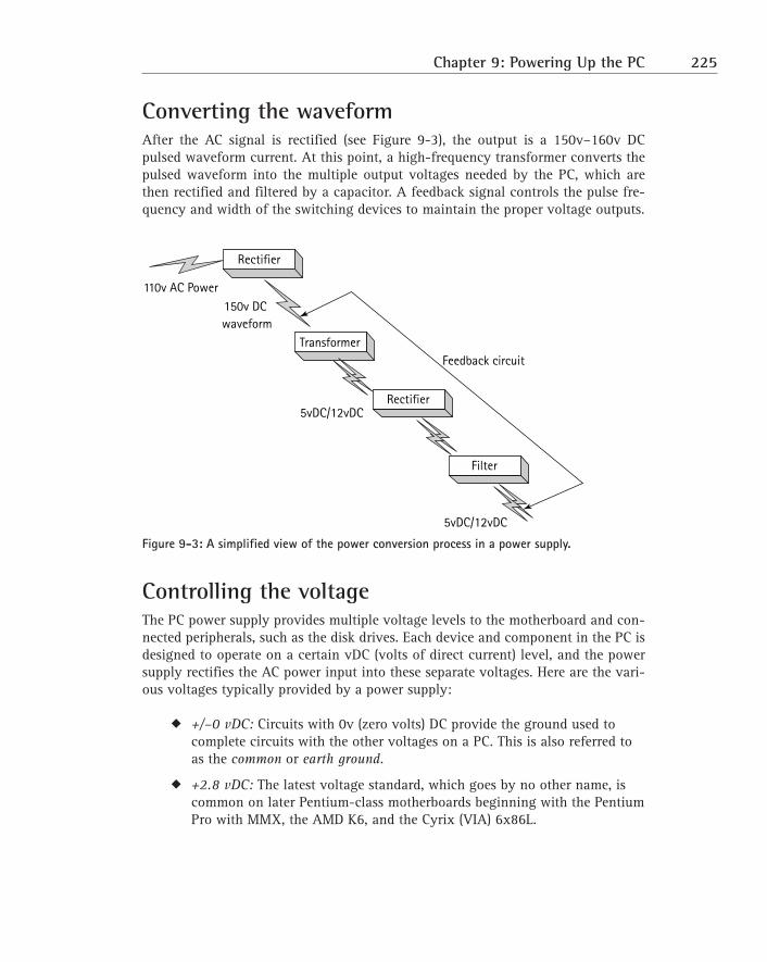
Converting the waveformAfter the AC signal is rectified (see Figure 9-3), the output is a 150v–160v DCpulsed waveform current. At this point, a high-frequency transformer converts thepulsed waveform into the multiple output voltages needed by the PC, which arethen rectified and filtered by a capacitor. A feedback signal controls the pulse fre-quency and width of the switching devices to maintain the proper voltage outputs.
Figure 9-3: A simplified view of the power conversion process in a power supply.
Controlling the voltageThe PC power supply provides multiple voltage levels to the motherboard and con-nected peripherals, such as the disk drives. Each device and component in the PC isdesigned to operate on a certain vDC (volts of direct current) level, and the powersupply rectifies the AC power input into these separate voltages. Here are the vari-ous voltages typically provided by a power supply:
� +/–0 vDC: Circuits with 0v (zero volts) DC provide the ground used tocomplete circuits with the other voltages on a PC. This is also referred toas the common or earth ground.
� +2.8 vDC: The latest voltage standard, which goes by no other name, iscommon on later Pentium-class motherboards beginning with the PentiumPro with MMX, the AMD K6, and the Cyrix (VIA) 6x86L.
Rectifier
Transformer
110v AC Power150v DC waveform
5vDC/12vDC
5vDC/12vDC
Feedback circuit
Rectifier
Filter
Chapter 9: Powering Up the PC 225
See Chapters 1 and 2 for more information on motherboards and proces-
sors, respectively.
� +3.30 vDC: Also called standard voltage. This voltage is common on theATX, NLX, and other newer form factors to provide power to PentiumCPUs, memory, Accelerated Graphics Port (AGP) ports, and the other com-ponents on the motherboard.
� +3.38 vDC: Also called voltage reduced (VR). Before the ATX form factor,voltage regulators on the motherboard were used to reduce +5 vDC to+3.38 vDC, which is why it is referred to as reduced.
� +3.50 vDC/+3.52 vDC: Also called voltage reduced extended (VRE). Thesevoltages are Intel adaptations of the VR standard.
� +5 vDC: Also called system +5 volts. Prior to the second generation ofPentium processors, this was the primary voltage on the motherboard forCPUs and most of their attached components. This is the standard voltageon Baby AT power supplies and those preceding it. Most newer systemsnow use +3.3 vDC.
� –5 vDC: This voltage level is now essentially obsolete. It was used onsome of the earliest PCs for floppy disk controllers and Industry StandardArchitecture (ISA) bus cards. For backward-compatibility purposes, mostpower supplies still generate this voltage, but it mostly goes unused.
� +12 vDC: This voltage level is used to power devices directly connected tothe power supply, such as disk drive motors, the main cooling fan, andother similar devices. Rarely is it used by the motherboard in a modernPC; instead, it’s passed onto the system bus slots for any cards that mightneed it. Of course, drives are connected directly to the power supplythrough their own connectors.
� –12 voc: Like –5v, this voltage is a holdover from earlier systems, where itwas used on some serial ports. Most power supplies provide this voltagefor backward compatibility with older hardware.
226 Part II: The System Case and Power Supply
Factoring power supply formsPower supplies, like motherboards (see Chapter 1), are available in a variety of dif-ferent form factors, typically matching the form factor of the motherboard and sys-tem case. With the exception of the early IBM PCs, most AT-class power supplies(which include the AT, Baby AT, ATX, and others) are roughly the same, differingonly in their size and mounting requirements.
The size and shape of the system case has a direct bearing on the capabilitiesdemanded of its power supply. Tower cases (see Chapter 8 for more information onsystem cases) are usually larger and require more watts of power output to run theirhard drives, cooling systems, and accessories. Desktop or mini-tower cases aresmaller overall and usually have fewer internal devices needing power, thus need-ing fewer watts of output from the power supply.
In general, a power supply’s form factor refers to its general physical shape, fit,and size. A power supply’s form factor must be the same as the system case and, inmost instances, the same as the motherboard. Because the power supply is typicallypurchased as a part of the system case, matching the two is rarely an issue. Onlywhen a power supply must be replaced does its form factor — and that of the caseand motherboard — come up. However, newer designs of power supplies are com-patible with more than one case form factor, and some cases can take any one ofmany power supply form factors. Take care to match the power requirements of themotherboard to the power supply, though.
Here is an overview of each of the form factors of the past and present:
� PC XT: The IBM PC and the IBM PC XT (extended technology) establishedthe first form factor for power supplies as well as cases and motherboards.These desktop systems placed the power supply in the rear-right corner ofthe case, and an up-and-down toggle switch on the exterior of the powersupply was used to power it on and off. The PC XT power supply was usedin many early AT clones as well.
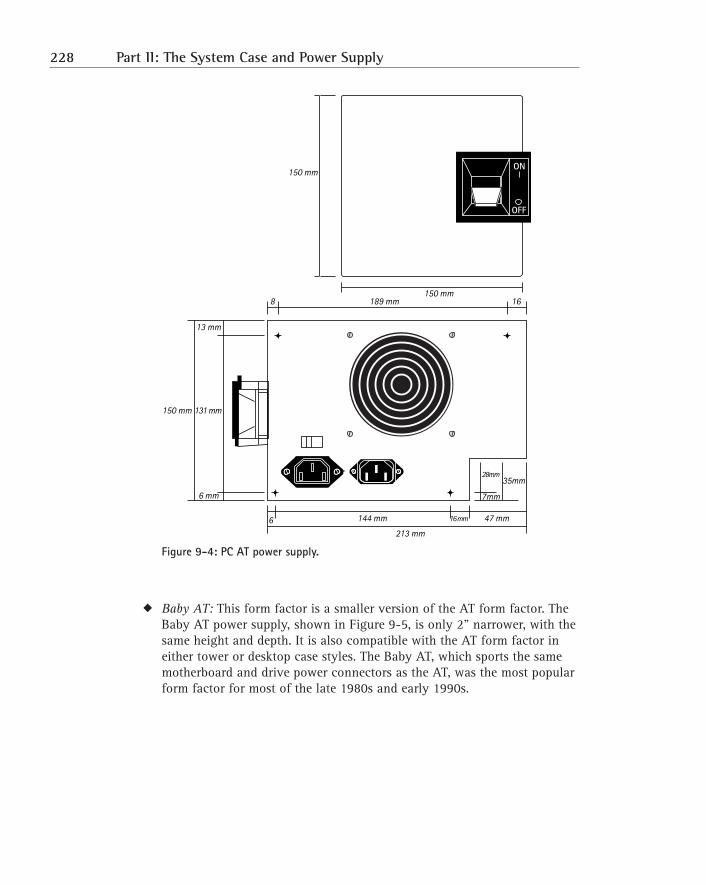
� AT: The power supply of the IBM PC AT (advanced technology; see Figure9-4) was a little larger and had a slightly different shape and about threetimes the power wattage of the PC XT. The AT standard soon became theform factor of choice among clone manufacturers, who built a wide vari-ety of AT-compatible systems. The AT form factor was the foundation ofseveral form factors that followed.
Chapter 9: Powering Up the PC 227
Figure 9-4: PC AT power supply.
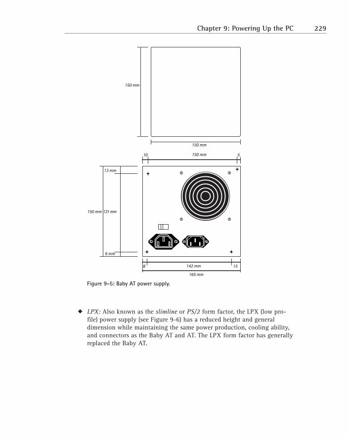
� Baby AT: This form factor is a smaller version of the AT form factor. TheBaby AT power supply, shown in Figure 9-5, is only 2" narrower, with thesame height and depth. It is also compatible with the AT form factor ineither tower or desktop case styles. The Baby AT, which sports the samemotherboard and drive power connectors as the AT, was the most popularform factor for most of the late 1980s and early 1990s.
35mm
150 mm
150 mm189 mm
144 mm 47 mm16 mm
213 mm
8
6
16
13 mm
131 mm150 mm
6 mm 7mm
28mm
ON
OFF
228 Part II: The System Case and Power Supply
Figure 9-5: Baby AT power supply.
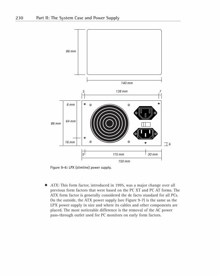
� LPX: Also known as the slimline or PS/2 form factor, the LPX (low pro-file) power supply (see Figure 9-6) has a reduced height and generaldimension while maintaining the same power production, cooling ability,and connectors as the Baby AT and AT. The LPX form factor has generallyreplaced the Baby AT.
150 mm
150 mm
150 mm
8
10 5
15
13 mm
131 mm150 mm
142 mm
165 mm
6 mm
Chapter 9: Powering Up the PC 229
Figure 9-6: LPX (slimline) power supply.
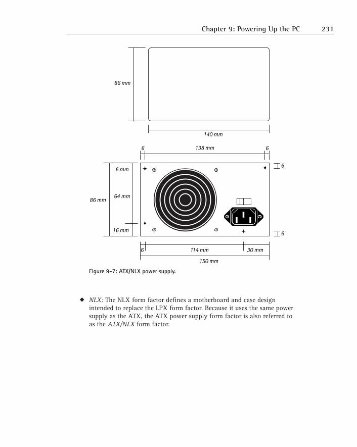
� ATX: This form factor, introduced in 1995, was a major change over allprevious form factors that were based on the PC XT and PC AT forms. TheATX form factor is generally considered the de facto standard for all PCs.On the outside, the ATX power supply (see Figure 9-7) is the same as theLPX power supply in size and where its cables and other components areplaced. The most noticeable difference is the removal of the AC powerpass-through outlet used for PC monitors on early form factors.
138 mm
150 mm
6 mm
64 mm86 mm
16 mm
5 115 mm 30 mm
140 mm
86 mm
5
6
7
230 Part II: The System Case and Power Supply
Figure 9-7: ATX/NLX power supply.
� NLX: The NLX form factor defines a motherboard and case designintended to replace the LPX form factor. Because it uses the same powersupply as the ATX, the ATX power supply form factor is also referred toas the ATX/NLX form factor.
138 mm
150 mm
6 mm
64 mm86 mm
16 mm
6 114 mm 30 mm
140 mm
86 mm
6 6
6
6
Chapter 9: Powering Up the PC 231
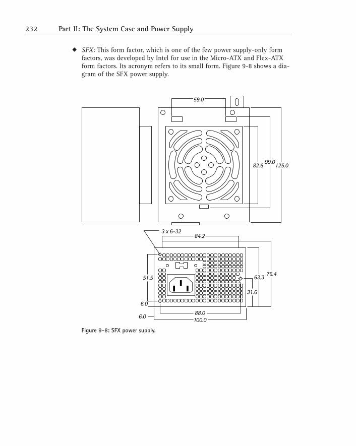
� SFX: This form factor, which is one of the few power supply-only formfactors, was developed by Intel for use in the Micro-ATX and Flex-ATXform factors. Its acronym refers to its small form. Figure 9-8 shows a dia-gram of the SFX power supply.
Figure 9-8: SFX power supply.
59.0
82.6 125.099.0
3 x 6-3284.2
31.6
63.3 76.4
88.0100.0
51.5
6.0
6.0
232 Part II: The System Case and Power Supply
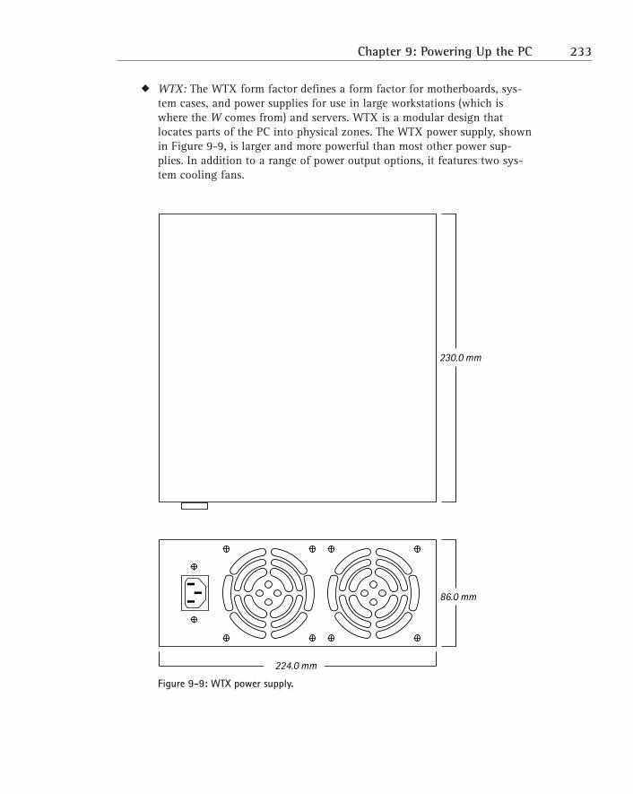
� WTX: The WTX form factor defines a form factor for motherboards, sys-tem cases, and power supplies for use in large workstations (which iswhere the W comes from) and servers. WTX is a modular design thatlocates parts of the PC into physical zones. The WTX power supply, shownin Figure 9-9, is larger and more powerful than most other power sup-plies. In addition to a range of power output options, it features two sys-tem cooling fans.
Figure 9-9: WTX power supply.
224.0 mm
86.0 mm
230.0 mm
Chapter 9: Powering Up the PC 233
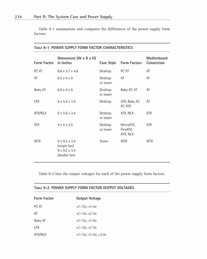
Table 9-1 summarizes and compares the differences of the power supply formfactors.
TABLE 9-1 POWER SUPPLY FORM FACTOR CHARACTERISTICS
Dimensions (W x D x H) Motherboard Form Factor in Inches Case Style Form Factors Connection
PC XT 8.8 x 5.7 x 4.8 Desktop PC XT AT
AT 8.5 x 6 x 6 Desktop AT ATor tower
Baby AT 6.6 x 6 x 6 Desktop Baby AT, AT ATor tower
LPX 6 x 5.6 x 3.4 Desktop LPX, Baby AT, ATAT, ATX
ATX/NLX 6 x 5.6 x 3.4 Desktop ATX, NLX ATXor tower
SFX 4 x 5 x 2.5 Desktop MicroATX, ATXor tower FlexATX,
ATX, NLX
WTX 6 x 9.2 x 3.4 Tower WTX WTX(single fan)9 x 9.2 x 3.4(double fan)
Table 9-2 lists the output voltages for each of the power supply form factors.
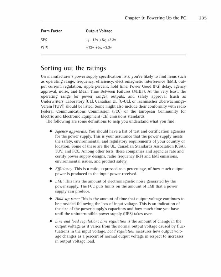
TABLE 9-2 POWER SUPPLY FORM FACTOR OUTPUT VOLTAGES
Form Factor Output Voltage
PC XT +/–12v, +/–5v
AT +/–12v, +/–5v
Baby AT +/–12v, +/–5v
LPX +/–12v, +/–5v
ATX/NLX +/–12v, +/–5v, +3.3v
234 Part II: The System Case and Power Supply
Form Factor Output Voltage
SPX +/– 12v, +5v, +3.3v
WTX +12v, +5v, +3.3v
Sorting out the ratingsOn manufacturer’s power supply specification lists, you’re likely to find items suchas operating range, frequency, efficiency, electromagnetic interference (EMI), out-put current, regulation, ripple percent, hold time, Power Good (PG) delay, agencyapproval, noise, and Mean Time Between Failures (MTBF). At the very least, theoperating range (or power range), outputs, and safety approval (such asUnderwriters’ Laboratory [UL], Canadian UL [C-UL], or Technischer Uberwachungs-Verein [TUV]) should be listed. Some might also include their conformity with radioFederal Communications Commission (FCC) or the European Community forElectric and Electronic Equipment (CE) emissions standards.
The following are some definitions to help you understand what you find:
� Agency approvals: You should have a list of test and certification agenciesfor the power supply. This is your assurance that the power supply meetsthe safety, environmental, and regulatory requirements of your country orlocation. Some of these are the UL, Canadian Standards Association (CSA),TUV, and FCC. Among other tests, these companies and agencies rate andcertify power supply designs, radio frequency (RF) and EMI emissions,environmental issues, and product safety.
� Efficiency: This is a ratio, expressed as a percentage, of how much outputpower is produced to the input power received.
� EMI: This lists the amount of electromagnetic noise generated by thepower supply. The FCC puts limits on the amount of EMI that a powersupply can produce.
� Hold-up time: This is the amount of time that output voltage continues tobe provided following the loss of input voltage. This is an indication ofthe size of the power supply’s capacitors and how much time you haveuntil the uninterruptible power supply (UPS) takes over.
� Line and load regulation: Line regulation is the amount of change in theoutput voltage as it varies from the normal output voltage caused by fluc-tuations in the input voltage. Load regulation measures how output volt-age changes as a percent of normal output voltage in respect to increasesin output voltage load.
Chapter 9: Powering Up the PC 235
� Mean Time Between Failures (MTBF): This is generally an estimate basedon the manufacturer’s testing of how long the power supply will runbefore a failure. The larger this number is, the better.
� Noise: This is a rating in decibels (dB) of the actual noise that the powersupply produces. Most of the noise produced from the power supplycomes from the fan. Each 3 dB increment represents a 100 percentincrease in the volume of the noise level.
� Operating range: This measures the minimum and maximum range of inputvoltages that the power supply can receive and still maintain an acceptableoutput voltage. A wide range denotes a power supply that can providesteady output even in areas with an unreliable or dirty power source.
� Output current: This is the maximum current in volts that the power sup-ply can consistently produce and supply to the motherboard and the diskdrives.
� PG delay: This is the amount of time that the power supply delays beforesending the Power Good signal to the motherboard. This time is necessaryto allow the power supply to warm up and start producing good DC power.
� Ripple percent: This is the amount of variance in the DC output levelsbecause of incomplete rectification and filtering of the AC power input.
Protecting the PCThe power supply accounts for nearly one-third of the problems on a PC. This doesn’tinclude the problems caused by the power supply that cannot be directly attributedto it, such as electronic components that are damaged over time by a faulty powersupply. What causes the most problems with a power supply is the AC powersource, which is generally an unreliable, noisy, and fluctuating electrical source.
Identifying electrical evilsA number of bad things are associated with AC power, most of which your PC canbe protected against. You should be aware of these common electrical problems,listed here in their severity (at least in my opinion):
� Spike: An electrical spike is an unexpected, (usually) short-duration, high-voltage event on the AC power line. A spike can be caused by a variety ofevents, such as lightning strikes, generator switchovers, power pole inci-dents (a car hitting one, for example), or large electrical motors on thesame power source. The safeguard against an electrical spike is a surgesuppressor or an UPS that includes surge suppression.
236 Part II: The System Case and Power Supply
� Power surge: A power surge (over-voltage) is a high-voltage situation thatraises the voltage above normal levels much like a spike but for a longerperiod of time. Often, it’s a spike followed by a slow tapering of the powerlevel back to normal. A large nearby electrical user can cause the powerlevel on the source lines to surge or drop if that user suddenly cuts itspower consumption. Although not as instantly damaging as a spike,surges can cause component failures, nonetheless. A surge suppressor or aUPS, which absorbs the increase in power, is good protection against apower surge.
� Noise: EMI and RFI are the two primary causes of line noise on the ACpower line. Power cables can act as an antenna and pick up disruptivesignals emitting from computer monitors, fluorescent lighting, electricalmotors, radio transmitters, and natural phenomena, such as lightning.Avoid placing any device that causes an interruption or static on anamplitude modulation (AM) radio on the same electrical circuit as a PC.Some surge filters also include noise filters, but unless you’re using a lineconditioner, a UPS is your best bet to filter out line noise.
� Blackout: A blackout is a total loss of power. It can last anywhere from asplit second to many days. If your power supply’s Hold Up Time is greaterthan the amount of time that you’re without power, you’ll probably onlynotice a momentary flickering or dimming of your screen. The averageHold Up Time is around 1⁄20 of a second. Anything longer than that, andyour PC will probably reboot itself. The best defense against a blackout isa UPS.
� Brownout: A brownout is the opposite of a spike, except that a brownoutcan last for some time. If the voltage lingers too long below the nominalpoint, the result can be the same as a blackout or worse. Brownouts candestroy components by causing a power supply to draw too much currentto make up for the low voltage. A UPS can protect against a brownout bymaking up the difference between the low voltage level and what is thenormal voltage level.
Suppressing the surgeMany of the power strips and plug strips on the market, like the one shown inFigure 9-10, also contain surge suppressors (also know as surge protectors). Theactive component in a surge suppressor is a metallic oxide varistor (MOV) thatreacts to over-voltage situations and diverts (or shunts) the power to a groundingcircuit.
Surge suppressors are rated by the amount of electrical power that they candivert. The measurement unit is Joules, which measures the amount of electricitythat the suppressor can absorb and not pass through. An MOV is essentially a one-shot device, much like a fuse. If an MOV is triggered by a power surge, its life (andusefulness) is over. And in most cases, you cannot tell whether it’s been triggered.
Chapter 9: Powering Up the PC 237
Figure 9-10: A plug strip that includes a surge suppressor.
Some power strips include a lighted fuse in series with the MOV that should alsoblow when a surge takes out the MOV. Sometimes the lighted fuse blows with asmaller surge, leaving the MOV to handle the next large surge or group of smallersurges. On the other hand, the fuse can be strong enough to withstand a small surgethat might be strong enough to wear down the MOV. It might not take all that manysmall surges to knock out the MOV, while the fused light shines on.
Some surge suppressors have more advanced surge interception technology suchas gas discharge tubes and pellet arrestors, which are a little slower to react, butthese types of suppression devices can be used more than once.
UPS-scaling protectionA UPS is a large battery and battery charger that provides a PC or server with pro-tection against short-term power outages, surges, spikes, and brownouts. A UPSmonitors its input voltage (AC power), and when the voltage level deviates morethan a certain percentage from normal, switches electrical service from its battery.The DC battery power stored in the UPS is passed through an inverter to create anAC supply for the PC (which immediately converts it back to DC power). Figure9-11 shows the back panel of the type of UPS commonly found in an office setting.
The best UPSes supply power to the PC when needed in a smooth wave, which isprobably better than the original AC source. Less-expensive UPSes can provide thepower in a square wave, which can contain potentially harmful frequencies thatcan damage sensitive equipment. However, note this compromise between theexpensive and the inexpensive: namely, UPS units that produce a wave made up of several small square wave steps. Some unfavorable frequency harmonics stillexist — but a lot fewer. When buying a UPS, be sure that you’re aware of the type ofwave output that it provides.
238 Part II: The System Case and Power Supply
Figure 9-11: The back panel of an APC SU620Net uninterruptible power supply (UPS).
CATEGORIZING UPS DEVICESUPS units are available in two general categories based on how they store and pro-vide electrical power. The two categories are
� Standby UPS: This type of UPS generally does nothing more than providea battery backup to the PC connected to it as a safeguard against a powerfailure (blackout) or a low-voltage event (brownout). In standby mode, theUPS draws off a small amount of power to charge its battery and passesunfiltered AC power on to the PC. In the event of a blackout, the standbyUPS provides the PC with an AC power source. The switchover does takesome time, which increases the importance of the PC power supply’s hold-out time. If the hold-out is long enough to cover the switchover time, youshouldn’t have any serious problems. One of the downsides to moststandby units is that any large surges, spikes, or low-voltage events willmost likely be passed through the UPS to the PC.
� Online (or inline) UPS: An online (inline) UPS provides power to a PCthrough an AC power service provided from the UPS’ battery and a powerinverter that converts the battery’s DC power to AC power. The UPS’ bat-tery is constantly being recharged from an AC power source through aninput inverter. An online UPS requires no switchover because the UPSabsorbs any events, such as spikes and blackouts, on the AC power line. Anextended brownout would begin discharging the UPS’ battery, whichwould eventually fail without the AC power being restored. Essentially, thePC runs on AC produced by the battery, and the battery is being constantlykept charged while there is input power. Figure 9-12 shows a large inlineUPS that would be used to protect one or more servers on a network.
Chapter 9: Powering Up the PC 239
Figure 9-12: A rackmount UPS used for network servers.
UPS CHARACTERISTICSHere is a list of characteristics that you should keep in mind when choosing a UPS:
� Simple or interactive displays or warnings: Even the least-expensive UPSon the market tries to give a warning near the end of its charge. Low-end(meaning low-price) UPSes sound a beep at given battery charge levels,but it’s up to you to guess how much of the battery’s charge remains. Abetter UPS has light-emitting diode (LED) gauges to show the current levelof charge, as well as how much is being demanded, to allow you to makean educated guess as to how much time you have to shut down your sys-tem before the battery is dead. The best UPSes display an estimate in min-utes and seconds on their control panel based on the current battery leveland draw rate.
� Warning mechanisms: A UPS designed to support a single computer willgenerally have a serial “heartbeat” cable that’s attached to a serial (COM)port on the PC. The UPS generates a regular signal that’s monitored by abackground process running on the PC. If the UPS fails to signal — inother words, misses too many heartbeats — the monitoring software (typi-cally supplied by the UPS’ manufacturer or part of the PC’s operating sys-tem) tries to gracefully shut down the PC.
A UPS that features monitoring is very important to use with servers that
cache a lot of data in memory instead of on a hard disk to speed data access
times. In this case, if the power suddenly fails, all the cached data would be
lost if it couldn’t be saved to disk before a shutdown or sync request.
A newer UPS is as likely to use a USB cable as the serial cable. The heartbeat
signal can also be broadcast over a network from a UPS that supports multi-
ple servers. The UPS monitor checks incoming Transmission Control
Protocol/Internet Protocol (TCP/IP) messages and sorts out the information
240 Part II: The System Case and Power Supply
coming from its UPS. The downside to this is if the server loses communica-
tion with the UPS (pulled cable, bad hub, and so on), the server might shut
down even though power is available.
� Software interfaces: The software monitor that interacts with the UPS inreal time (see previous bullet) is typically supplied by the manufacturer ofthe UPS. At minimum, these software programs monitor the heartbeat sig-nal sent by the UPS to indicate that power is still available. If the UPSstops sending the signal, the software begins the process to perform a sys-tem shutdown. Advanced systems are available that display console mes-sages, send an e-mail, or dial a pager to notify the system administrator.These systems also usually include support for remote status checking.
� Line conditioners and alarm systems: A true line conditioner (also knownas a power conditioner) filters the incoming power to isolate line noiseand keep voltage levels normal. It isolates the input power source fromthe output power in a transformer stage. A line conditioner can’t protectagainst a power outage, but it can smooth out any intermittent under-and over-voltage (surge and spike) events that occur on the input source.When the input power becomes unreliable, a line conditioner (and mostUPS units for that matter) sends up an alarm if it detects that there aremore problems on the line than it can handle.
Working with Power SuppliesWhether diagnosing, troubleshooting, or repairing a power supply, the very firstthing that you must understand about working on a power supply is that you shouldnever — repeat, never— open the power supply case and work inside the unit.
The amount of electrical voltage stored in the capacitor of the power supply
is more than enough to hurt you — or perhaps worse. And if that isn’t
enough reason, you could accidentally damage the internal components of
the power supply, which could in turn destroy the motherboard, disk drives,
and other electrical parts of a PC.
However, you can use a number of processes to isolate power supply problems.In the following sections, I detail the processes used for the most common power-supply-related problems on a PC.
Chapter 9: Powering Up the PC 241
Gathering the toolsHere is a list of tools that you need, followed by some general troubleshooting stepsused when working with power supplies:
� Diagonal cutters
� Screwdrivers (including Torx bits)
� Needle-nose pliers
� Multimeter or digital voltage meter (DVM)
� An AC power monitor that plugs into a wall outlet (such as Tasco)
� Soldering iron
� Cable ties
� Continuity tester
� Variac (variable power supply)
Notice that an electrostatic discharge (ESD) wrist strap is missing from this
list. The power supply has a big nasty capacitor in it that you really don’t
want to ground through your body. But you weren’t planning to open up
the power supply, anyway, were you (hint, hint)? If the power supply is bad,
it’s generally inexpensive to replace the whole thing.Those big, bright warn-
ing labels aren’t there for decoration. Read them and heed their warnings.
Deciding when to troubleshoot a power supplyThe power supply is obviously a very important component of the PC, but did youknow that it’s also the one most likely to fail? Day in and day out, it suffers theslings and arrows of mean and nasty electrical power, sacrificing itself for the goodof your computer. A recent study shows that on average, the common workstationor desktop PC suffers over 120 power events every month. Not surprisingly, it candevelop problems.
Three conditions require that you check out or troubleshoot the power supply:
� Upgrading the system: You’re planning a big upgrade (new motherboard,new hard drive, DVD, and the works) and you’re worried that your powersupply could be too weak to handle the new load.
242 Part II: The System Case and Power Supply
When upgrading, remember that a power supply is rated by its power out-
put in watts. You can get from 100- to 600-watt power supplies to fit the
common form factors (ATX and LTX). Unless you’re planning to build a super-
server with quad Pentium Xeons, a DVD, an internal tape drive, and four or
five internal Small Computer System Interface (SCSI) drives (in which case
you’ll need to look into the WTX form factor), a power supply rated between
230–350 watts works well for most average systems.
� Intermittent problems: If to no avail, you’ve tried everything that you canto track down an intermittent problem on the motherboard without isolat-ing the problem, the power supply might be the real culprit if the problemis at all related to a power issue.
How can you tell whether the power supply is going bad? These telltalesigns can tip you off that the power supply is on its way to failure: over-heating, occasional boot failures or errors, frequent parity errors, noisyoperation, or mild electrical shocks when you touch the case.
If you ever receive a shock other than ESD when you touch the case, you
have power supply problems of the first magnitude. Replace the power sup-
ply immediately!
� Catastrophic problems: If smoke is coming out of the power supply or offthe motherboard, the power supply has probably gone awry and needs tobe replaced. If the system fan has stopped turning, you absolutely need toreplace the power supply. You should also test the motherboard with anew power supply and also be on watch for parity errors, system lockupsthat become more frequent, and disk read and peripheral input/output(I/O) errors. These are signs of damaged motherboard components begin-ning to fail.
Isolating the power supply as a source of aproblemHere are some steps that you should use any time that you suspect that the powersupply is the source of a PC problem:
1. First, determine that the problem isn’t something as trivial as a blown fusecaused by a legitimate overload.
Chapter 9: Powering Up the PC 243
Be sure to remove the source of the overload before beginning work.
2. Try to classify the problem by when it occurs and what it affects. The cat-egories that you might use are a BIOS, boot, or startup problem; an inputpower-related problem; an output power-related problem; excessive noise,ripple, or other power conversion errors; or a catastrophic failure thatposes a danger to the system or the operator (especially the technician).
3. Based on the form factor, determine what the proper output voltagesshould be and measure the output of the appropriate pins.
Read the documentation for your power supply. Some power supplies can-
not have their electrical load removed (meaning that they must stay con-
nected to the motherboard or disk drives) without causing damage to the
power supply. AT power supplies and earlier form factors are generally safe
to remove, but check the documentation anyway.
Ruling out the power supplyIf the general steps listed in the previous section don’t solve or identify a problemwith the power supply — or if they prove inconclusive — the problem could still bethe power supply even when the problem shows up elsewhere. You can safely betthat when an electrical power problem exists on the PC (regardless of where itshows up), the power supply is involved in the cause in some way.
One of the quickest and easiest ways to troubleshoot a computer power supply isto put your hand in front of the cooling fan. If you don’t feel any air passing intoor out of the fan, chances are that the power supply is bad. One exception to thistest is that an ATX form factor motherboard might have a bad PS_ON switch.
The most effective way to absolutely, positively tell whether a power supply isthe cause of a problem is to swap it out. If the problem is solved after you install areplacement power supply, there you are. However, if the new power supply doesn’tsolve the problem, the problem lies elsewhere. Don’t jump to the conclusion thatthe old power supply is vindicated. Before you decide to put the old power supplyback in its PC or put it on the shelf as a ready spare, try putting it in another sys-tem to see whether it works there. Unfortunately, some problems that can be causedby a power supply with a low-level or intermittent problem can take days, weeks,or months to show up.
If the computer case is still under warranty, you don’t have to send the entire
computer case back just to return a faulty power supply.The computer case
has at least four or five major components, and the power supply is one of
two electrical parts (the other is the front panel) that can be Dead on Arrival
244 Part II: The System Case and Power Supply
(DOA). Most manufacturers or resellers will likely want to replace the faulty
part rather than the entire system case. Shipping back only the power sup-
ply will also save you money on the shipping charges.
Diagnosing POST power problemsYou can run into situations that require you to know the symptoms that indicate apower supply problem. Here are a few of the leading symptoms that indicate an ail-ing power supply:
� The power light on the front panel is off.
� The power supply fan isn’t operating.
� The computer either sounds a continuous beep or doesn’t beep at all.
� The computer sounds a repeating short beep.
� The computer displays either a POST error in the 020–029 series (PowerGood signal error) or a parity error.
Nothing happens when the power switch is turned onIf you switch on a PC and nothing happens (meaning no lights, beeps, and so on),here are some steps that you can use to determine whether the power supply is theproblem:
1. Check to see whether the PC’s power cord is plugged into an AC poweroutlet on a surge protector or a UPS and into the PC.
2. Check the surge suppressor switch to see whether it’s on and workingproperly. If it appears that no AC power is being provided, move the plugto a different outlet. If no power is available on more than one outlet,check the building’s circuit breakers.
3. If power is available at the wall plug, either the power supply’s switch isbad, or the power supply itself has completely failed.
In either case, you should replace the power supply.
The fan isn’t spinningThe fan is a very important part of the cooling system designed into the case andmotherboard form factor. If it’s not spinning, something is wrong — and if notreplaced, this could cause serious damage to the PC.
Chapter 9: Powering Up the PC 245
Never insert anything like a screwdriver blade into the fan to turn the blades
in an attempt to make it go.There is a serious shock hazard inside the power
supply.
Use compressed air to clean around the spindle of the fan, blowing the airthrough the fan grill that’s located on the outside of the case. Before you do this,remove the system case cover and perhaps even take the unit outside, depending onhow dirty it is. If nothing is obviously impeding the fan from spinning, immedi-ately replace the power supply.
Do not open the power supply to replace the fan because of the electrical
shock danger that lurks inside the power supply.
The PC doesn’t boot and has no sign of powerIf the PC doesn’t boot and shows no sign of power, here are some things to check:
1. Check whether the outlet (such as the surge suppressor, UPS, or wall out-let) into which the PC is plugged has power. If it does, check that the cordis seated tightly and snuggly at the PC end and plugged in all the way onthe outlet end.
2. Disconnect everything from the back of the computer except the powerand then boot the computer. If the PC boots, add back one connector at atime, rebooting after each one is added, until the PC fails to boot.
If the PC fails to boot after a certain device is added, switch your focus tothat device because the problem (this time) isn’t the power supply.
If the problem seems to have gone away after you reconnect all the devicesto the PC, the problem was probably a loose connection — or somethingelse that you should be looking for as an intermittent occurrence.
3. Obviously, if the computer won’t boot or power up with just the powercord attached, you should replace the power supply.
As you’ll find, the easiest way to solve a power supply problem, especiallypesky ones that are hard to pin down, is to replace the power supply andnot waste your time trying to track down a specific problem that willcause you to replace the power supply anyway.
246 Part II: The System Case and Power Supply
An ATX system doesn’t work when the power isturned onAn ATX power supply is soft-switched through the power supply switch on themotherboard and the functions in the system BIOS. An ATX power supply alsorequires a load to operate, and connecting it to the motherboard supplies a part ofthat load. Thus, if you install an ATX power supply in a system, don’t expect it towork until you connect it to a motherboard that also has a microprocessor, mem-ory, and a video card installed on it.
If you install an ATX power supply and it fails to power up, the problem couldlie in the motherboard, processor, memory, or video card — or not.
The ATX power supply, which is not compatible in Baby AT cases, allows forsoft-switching — controlling the power on and off functions under motherboardcontrol. The ATX power supply uses a one-piece connector that’s keyed to fit inonly one way, which prevents the possibility of frying the motherboard as well aspossibly injuring yourself. The power supply also eliminates the need for a mother-board voltage regulator by providing split voltage, which is a range of voltages,usually 12v, 5v, and 3.3v, to the motherboard.
Setting the input voltage selector switchIf you’re located in North America (Canada, United States, and Mexico), your volt-age selector (usually located on the back of the power supply near the fan grill)should be set to 110–115v. If you’re located in Europe or another country outside ofNorth America, the voltage selector switch should probably be set to 220–230v.
If your computer is a laptop, notebook, or other portable computer manufac-tured in the past few years, it probably has a built-in voltage detector that auto-matically switches the voltage setting for you.
Because the vast majority of cases and power supplies are manufactured outsideof North America, the power supply was probably tested with a 220v setting. If thissetting isn’t reset for 110v for use in North America, when you first plug in a PCright out of the box, it will appear to be DOA because of a dead power supply.Before you use any PC right out of the box — except notebook computers — firstcheck the voltage selector switch to make sure that it’s set for the right voltage.
Testing power supply peripheral connectors with a DVMIf you keep a PC for any time at all, you’ll probably need to replace the power sup-ply at some point. Here are the steps used to test the power leads going to theperipheral devices:
1. Turn off the PC.
If the PC is an AT or earlier form factor, it should remain connected to thewall outlet. However, if it’s an ATX or later, unplug it from the wall outlet.
Chapter 9: Powering Up the PC 247
ATX motherboards are always on and carry enough juice to power up thePC. Therefore, unplugging these systems before placing metal objects,such as screwdrivers, inside the case is a good idea.
2. Remove the system case covers, watching for any grounding wiresattached to the case.
If you have one or more of these wires, leave them attached if possible.
3. Set your DVM or multimeter to read DC volts in the range higher than12v.
4. Locate a power supply connector (see Figure 9-13), either an unused oneor by disconnecting one from the floppy disk or CD-ROM.
Figure 9-13: A peripheral power connector.
You use this connector to perform a test on the power supply. The pinningthat you will need for the test is listed in Table 9-3.
5. Power on the PC.
6. Insert the black probe of the DVM (it should have two probes: a black anda red) into the power connector on one of the two black wires in the cen-ter two holes. See Figures 9-13 and 9-14.
7. With the black probe in place, touch the red probe to the connector on thered wire of the power connector.
You should get a reading of +5v DC.
8. Touch the red probe to the connector on the yellow wire of the powerconnector.
You should get a reading of +12v DC.
9. If either or both of the readings in Steps 7 and 8 are wrong, retest.
If neither test gives a reading, replace the power supply.
Red wireYellow wire
Black wires
248 Part II: The System Case and Power Supply
Figure 9-14: The floppy drive power connector.
TABLE 9-3 POWER SUPPLY CONNECTOR PINOUTS
Pin Signal Color
4 +5v DC Red
3 Ground Black
2 Ground Black
1 +12v DC Yellow
Correctly sizing a UPSA UPS is rated in volt-amps (VA) and can range from 200VA to greater than5000VA. With a UPS, you definitely get what you pay for. The higher the volt-amps, the more powerful the UPS is — and in direct proportion, the higher the pricetag will be.
The VA rating of a UPS is the amount of VA that the UPS can supply for a five-minute period. A UPS with a 500VA rating can deliver 500VA for five minutes. Thisassumes that the UPS has a load equal to its rating. If the load on a 500VA UPSwere only 250VA, the UPS would be able to supply power for 20 minutes.
Before picking the UPS for your PC, you should determine the amount of VAthat it needs to continue running for as long as you need it. Fifteen minutes is gen-erally considered ample time to shut down a system properly without a loss of data.Remember that the more VA a UPS is rated for, the more it will cost. You can cer-tainly find a UPS to power your PC for an hour, but the cost will be very high.
Red wireYellow wire
Black wires
Chapter 9: Powering Up the PC 249
Use the following calculation to determine about how long you have before yourUPS is exhausted:
(Max. amp draw x 120) + (Power supply (in watts) x 1.4) = Total Volt Amps Required
Here is what the terms included in the above formula mean:
� Maximum amp draw x 120: This calculates the total amps of all thedevices in or attached to the PC to be powered by the UPS, including theinternal devices (such as the hard disk, CD-ROM, and the like) and theexternal devices (such as the monitor or modem).
� Power supply (in watts) x 1.4: This calculates the watts rating of yourcomputer’s power supply.
After you calculate the total VA required, how much of the UPS’ reserve powerthat you wish to draw has a direct bearing on how long it can supply power to yoursystem:
� Full draw: Drawing as many volt-amps as the UPS’ rating should provideyou with about seven minutes of power.
� Half draw: Placing a load on the UPS at about one-half its rating providesabout 20 minutes of power.
For example, if the total volt-amps required by a PC is 350 and the UPS’ ratingis 700VA, the UPS should supply power for at least 15 minutes and perhaps as longas 20 minutes.
Table 9-4 lists the VA draw for several common peripheral devices. The manu-facturer or reseller of your PC should be able to tell you the VA requirements ofyour entire system. You can also try checking Web sites of the manufacturers ofeach of the major components of the PC.
TABLE 9-4 COMMON VA USAGE
Device or Component VA Usage
CD-ROM 20–25
Small expansion card 5
Large expansion card 10–15
3.5" floppy drive 5
250 Part II: The System Case and Power Supply
Device or Component VA Usage
Pentium II processor 38
Motherboard 20–35
Taking preventive measuresThings that you can do to lengthen the life of a power supply include many envi-ronmental, hardware-related, and common sense activities:
� The better the environment is for the PC, the better it will perform, justlike for its human operator. Run the computer in a cool, moderatelyhumid environment. The cooler the air entering the fan, the better. Thepower supply produces heat like all other transformers. Use an air-conditioned room if possible.
� Either reduce the amount of dust and smoke in the air around the com-puter or plan to clean the inside of the system case and fan often. Blowthe dust bunnies off the fan and power supply grills frequently with com-pressed air. It can’t hurt to do the same for the inside of the case occa-sionally, either.
� Use a surge protector — or better yet, a true line conditioner — and by allmeans, a UPS.
Chapter 9: Powering Up the PC 251
Storage DevicesCHAPTER 10
Working with Hard Disks
CHAPTER 11Hard Disk Interfaces
CHAPTER 12Floppy Disks and Removable Storage Devices
CHAPTER 13CD-ROM and DVD
Part III
Chapter 10
Working with Hard DisksIN THIS CHAPTEROriginally, PCs didn’t have hard disk drives, but it’s now hard to imagine a PC with-out one. Virtually every PC sold over the last eight or more years has had at leastone hard disk drive.
Primary storage is the PC’s main memory or RAM (see Chapter 6 for more infor-mation about memory) and serves as the PC’s active storage that temporarily storesdata and instructions while they’re in use by the system. The hard disk (along withthe floppy disk and CD-ROM) is a secondary storage device that provides permanentstorage for the user’s data, programs, and other objects, even after the power goesoff. In this chapter, I discuss
� How a hard disk is organized
� The parts of a hard disk
� How a disk accepts, reads, and writes data
� How to partition, format, and install a hard disk
THE HARD DISK is by far the most commonly used form of secondary storage. Thefuture of disk storage definitely includes the hard disk drive, although not perhapsin the form that you know today.
Studying the Hard Disk DriveThe hard disk used in virtually all PCs is derived from mainframe fixed disks of the1960s/1970s and the early Winchester drives, which were introduced in the 1980sand provided a prototype for today’s hard disks. The technology used to record dataon a hard disk has remained essentially the same as that used on the early drives,although the size of the drive is quite smaller, its speeds are much faster, and thecapacity is very much larger.
Because the floppy disk came first, hard drives were given the moniker hard
to differentiate them from floppy disks.
255
Organizing data on a disk driveHard disks (and floppy disks) organize media into logical divisions: cylinders,tracks, sectors, and clusters. This organization, along the servo system on the disk(see “Servo systems” later in this chapter), is the foundation of the addressing sys-tem used to locate, store, and retrieve data on the disk.
The basic organization elements on hard and floppy disks are
� Tracks: A floppy disk has around 80 tracks, and a hard disk can have1,000 tracks or more. Figure 10-1 illustrates how disk tracks are concen-tric bands that complete one circumference of the disk. The first track ona disk, typically track 0, is on the outside edge of the disk.
Figure 10-1: Tracks and sectors on a disk.
� Sectors: Disks are divided into cross-sections that intersect across alltracks, as illustrated in Figure 10-1. The result is that each track is brokeninto a number of addressable pieces, called sectors. A sector is 512 bytesin length; a hard disk has from 100 to 300 sectors per track, and a floppydisk from 9 to 18 sectors per track. Sectoring creates addressable elementson a track, including its starting point.
� Cylinders: All the tracks with the same number on all the platters (the flatround metallic disks located inside the hard disk) of a hard disk drive cre-ate a logical entity called a cylinder. The read/write heads of a disk movein unison and are all over the same track number on each disk platter. Ahard disk with three platters, as illustrated in Figure 10-2, has six disksurfaces and six track 52s, which logically create cylinder 52. Cylindersare not used on floppy disks.
Track
Sector
256 Part III: Storage Devices
Figure 10-2: Disk cylinders are made up of the same tracks on each platter.
� Clusters: Clusters are logical groupings of disk sectors used by operatingsystems to track and transfer data to and from the disk. Typically, a clus-ter comprises around 64 sectors, but the total capacity of the disk driveand the operating system determine the number of sectors in a cluster onany particular PC. Operating systems that use clusters as the basic transferunit operate in block mode.
Reviewing disk capacitiesDisk drive capacities are stated in megabytes (millions of bytes; MB) and gigabytes(billions of bytes; GB), but drives with terabyte (trillions of bytes; TB) capacity arebeginning to appear. Table 10-1 lists the common data capacity measurements usedwith disk drives.
TABLE 10-1 DATA CAPACITY MEASUREMENTS
Measurement Abbreviation Capacity
Kilobyte K One thousand bytes
Megabyte MB One million bytes
Gigabyte GB One billion bytes
Terabyte TB One trillion bytes
Continued
Track 52
Track 52
Cylinder 52
Track 52
Track 52
Track 52
Track 52
Chapter 10: Working with Hard Disks 257
TABLE 10-1 DATA CAPACITY MEASUREMENTS (Continued)
Measurement Abbreviation Capacity
Petabyte PB One quadrillion bytes
Exabyte EB One quintillion bytes
Most hard disk drives available today are in the 1 to 40GB range and come in
many different types and styles. However, they use the same basic compo-
nents, are constructed essentially the same way, and operate the same.
Where they differ is in their storage capacities and speeds, how they encode
the data, and the interface used to communicate with the PC.
Looking inside the disk driveA typical hard disk has the following major components (see Figure 10-3):
� Disk platters
� Spindle and spindle motor
� Storage media
� Read/write heads
� Head actuators
� Air filter
� Logic and controller boards
� Connectors and jumpers
258 Part III: Storage Devices
Differentiating Logical and Physical EntitiesWhen discussing disk drives, the term logical is used quite often, usually in a contextthat’s not all that logical at all. A logical entity is one that’s created logically, meaningwith software. For example, when a disk is formatted (see “Formatting a hard disk drive”later in the chapter”), system software logically creates the tracks, sectors, cylinders,and so on that are used to address the disk. These entities don’t physically exist; that is,they’re not hard etched into the recording media permanently. Hope that helps.
Figure 10-3: The major components of a hard disk drive.
With the exception of the connectors and jumpers and the controller board, allthe other components on this list are inside the metal enclosure of the disk drive,called the Head Disk Assembly (HDA). The HDA is a sealed unit that is neveropened outside of the factory.
DISK PLATTERSPlatters, the primary components of a hard disk drive, are where data stored in thehard disk is recorded. Hard disk platters are made from two primary materials: alu-minum alloy and a glass-ceramic composite. Aluminum alloy has been used forhard disk platters almost from the beginning because it provides strength in a light-weight material. However, aluminum platters expand and flex when heated, whichcan resort in misreads and corrupted data. Consequently, a glass-ceramic materialis now used for most disk platters.
Glass-ceramic platters only need to be about half the thickness of an aluminumdisk to have the same rigidity. Glass disks do not expand nor contract as the tem-perature changes, which means the hard disk is more reliable. As the size of diskdrives continues to shrink while the amount of data is increasing, all hard disks willprobably be manufactured with glass-ceramic platters. Many of the top hard diskmanufacturers already use glass composite materials, including Seagate, Toshiba,and Maxtor.
Platters
Read/writehead
Air filter
Voice coil actuator
Spindle
Powerconnector
Jumpers
Dataconnector
Head arm
Actuator shaft
Chapter 10: Working with Hard Disks 259
PC hard drives have between one and ten platters, with the majority using twoplatters to store data. The smaller form factor hard disks use either one or two plat-ters. The number of platters used is controlled by the overall size of the disk drive.The form factor of the hard disk drive is derived from the diameter of its platters.However, the form factor can also represent the size of the drive bay into which thedrive can be installed.
The common hard disk form factors with the platter sizes in each are listed inTable 10-2.
TABLE 10-2 COMMON PC HARD DISK DRIVE FORM FACTORS
Form Factor Platter Size
5.25" 5.12" (130 millimeters [mm])
2.5" 2.5" (63.5 mm)
3.5" 3.74" (95 mm)
1.8" 1.8" (45.7 mm)
The 3.5" form factor drive is the most popular of the disk drives listed in
Table 10-2 and has been for some years now. Prior to that, the 5.25" drive was
used in most desktop and tower-style PCs. The 2.5" drive and 1.8" drives are
popular in notebook computers because of their size and weight.
Platters are mounted to a spindle inside the HDA (see Figure 10-4). The plattersare separated with disk spacers that keep them evenly spaced and provide the spaceneeded for the read/write heads to access the data on each side of the platter. Eachsurface of the platter is polished and covered with a very thin layer of magneticmaterial that is used to hold the electromagnetic charge representing the datastored on the disk.
SPINDLE MOTORAs I discuss in the preceding section, the platters are mounted to the disk spindle,as illustrated in Figure 10-4. The spindle (and the platters mounted to it) is rotatedby the spindle motor at speeds of 3,600, 4,800, 5,400, and 7,200 revolutions perminute (rpm). Many newer hard disk drives have rotational speeds of 10,000 or15,000 rpm. The spindle motor is a direct-drive motor mounted to the bottom onthe spindle assembly.
260 Part III: Storage Devices
Figure 10-4: The platters of the disk drive are attached to the disk spindle.
The spindle motor, shown in Figure 10-5, is connected directly to the spindle. Nobelts or gears are used in this mechanism in order to eliminate noise and vibrationthat could cause read/write problems on the platters. Two types of spindle motorsare used in hard disk drives: in-hub motors that are placed inside the HDA andbottom-mount motors that are placed outside the HDA. The spindle disk motor,which is a brushless and sensorless DC motor, is designed to prevent oil or dustfrom contaminating the sealed dust-free environment inside the HDA. Special sealsare placed in the spindle drive assembly to prevent the lubricating oil that can turninto a mist from the spindle motor’s high rotation rates from getting inside theHDA. The spindle motor is obviously a vital part of the disk drive’s operation, butbecause of its speeds and constant use, many hard disk failures are the result of aspindle motor failure.
Figure 10-5: Views of a spindle motor.
STORAGE MEDIAData is stored on a hard disk (or a floppy disk) by using electromagnetic principles(see “Recording data on the disk” later in this chapter) that are used to alter the
Disk platters
Spindle
Disk spacer
Spindle motor
Chapter 10: Working with Hard Disks 261
particles of the disk media placed on each side of a disk platter. The quality of thestorage media can directly affect the performance of the disk drive.
The two types of media used on hard disk platters are
� Oxide media: The type of media used on older disk drives, oxide media arerelatively soft materials that are easily damaged by a head crash (whenthe read/write head strikes the disk’s surface). The primary ingredient inoxide media is ferrous oxide (iron rust).
� Thin-film media: This is the media used on virtually all disk drives manu-factured today. Thin-film media is an extremely thin layer of metals thatis plated on disk platters by using a process similar to plating the chromeon your car. Thin-film media is harder and thinner, allowing strongermagnetic fields to be stored in smaller areas.
READ/WRITE HEADSThe hard disk’s read/write heads are constructed with a magnetic core that’swrapped by one or more electrical wires through which an electrical current ispassed in one direction or the other to change the polarity of the magnetic fieldemanating from the core. As the read/write head passes over the magnetic media,the polarity of the core is changed as needed to change the value stored in a certainlocation on the platter’s magnetic media (see “Storage media” earlier in this chap-ter for more information on the magnetic media on the disk platter).
Each side of a disk platter has magnetic media to store data and at least oneread/write head. Figure 10-6 illustrates a disk drive with two disk platters or fourread/write heads (one for each platter surface). The read/write head for each surfaceis connected to an actuator mechanism that moves the read/write heads in and outtogether, moving between the inside edge near the spindle to the outside edge ofthe platter. When the read/write head over the top platter (or disk 0) is over track29, all the other read/write heads are also over track 29 on the other platter sur-faces. While the read/write heads are moved around the disk surfaces, only onehead is active at a time.
Figure 10-6: Each platter has a read/write head for each of its sides.
Read/write heads Actuator shaft
Travel direction of headsSpindle
Platter
262 Part III: Storage Devices
HEAD ACTUATORSA head actuator positions the hard disk’s read/write heads by extending andretracting the heads over the platters. The two types of actuators used on modernhard disk drives are stepper motor and voice coil actuators. These two types ofactuators are very different. A stepper motor actuator is slow, sensitive to tempera-ture changes, and less reliable than a voice coil actuator. A voice coil actuator isfast, unaffected by temperature changes, and extremely reliable. Despite their defi-ciencies, stepper motor actuators are less expensive, which makes them desirable tosome manufacturers. The type of actuator used in a disk drive speaks volumesabout the drive’s performance, reliability, and cost.
A stepper motor is an electrical motor that moves in a series of steps. The motorcannot stop between steps and must advance from one step to the next to operate.On a disk drive that uses a stepper motor actuator to move the read/write heads, thestepper motor is located outside the HDA and connects to the head arm gangthrough a sealed hole in the HDA case. The stepper motor connects to the read/writeheads with either a flexible steel band wrapped around the actuator motor’s spindleor through a rack-and-pinion gearing arrangement. The steps of the actuator motorcoincide with the tracks on the disk. To move the read/write head’s ten tracks, thestepper motor must rotate ten steps. The biggest problem with this approach is thatthe head actuator arms can drift slightly off their original positions. A stepper motor
Chapter 10: Working with Hard Disks 263
What’s New in Read/Write Head Technology?The four types of read/write heads that have been or are currently used in hard diskdrives are
� Ferrite heads: This is the oldest, biggest, and heaviest of the magnetic headdesigns. Because of its size, it uses a larger floating height to guard againstcontacting the disk surface. Ferrite heads use an iron-oxide core that’s wrappedwith an electromagnetic coil, which is energized to create a magnetic field.
� Metal-in-Gap (MIG): This type of read/write head is an enhanced version ofthe ferrite head. Additional metal is added to the head on the leading andtrailing edges of the head gap that allows it to ignore nearby fields and focusonly on the fields beneath the head.
� Thin-film (TF): This type of read/write head is manufactured from semicon-ductor material (see Chapter 2) and is used in small form factor high-capacitydrives. They are light and much more accurate than the ferrite heads andoperate much closer to the disk surface.
� Magneto-resistive (MR): This type of head is used in most 3.5" disk driveswith a capacity over 1GB as the read head. Disk drives with MR heads typi-cally also have a TF head for writing data.
actuator uses a blind location system, which means that the disk heads must relysolely on the stepper motor to place them correctly over the track to be accessed.
Comparatively, nearly all disk drives with capacities above 80MB (which is justabout all currently manufactured disk drives) use a voice coil actuator. The technol-ogy used to create its core mechanism is very similar to the voice coil of an audiospeaker. The voice coil in a hard disk drive is an electromagnetic coil attached to theends of the arms on which the read/write heads are located. As the voice coil is ener-gized, it produces an electromagnetic field that, depending on the flow direction ofthe electricity used to energize it, either attracts or repulses a stationary magnetthat’s located opposite the voice coil actuator. As the voice coil moves away from orcloser to the stationary magnet, the read/write heads are extended or retracted.
A voice coil actuator doesn’t move in steps like the stepper motor actuator.Instead, it relies on a feedback system, called a servo, to position the heads over aparticular location on the disk. The servo, which is a block of data stored on thedisk, lets the actuator know exactly where its heads are on the disk. Unlike the blindlocation system of the stepper motor, a voice coil actuator receives feedback signalsfrom the servo that guides it exactly to the correct location.
Virtually all voice coil systems in use today use rotary voice coil actuators. Thisactuator system attaches its voice coil to an actuator arm that’s mounted like a pivot.As the coil moves to or from the stationary magnet, the head arm rotates in and out,moving the read/write heads over the disk. The one problem that develops with arotary voice coil is that as the heads are moved deeper into the disk (closer to thespindle), they tilt slightly. This tilt of the heads creates a problem with the alignmentof the heads to the disk, also known as an azimuth problem. Azimuth issues are typ-ically dealt with by not allowing data to be stored on the center part of the disk.
SERVO SYSTEMSServo systems are special coding stored on a formatted disk to help the read/writehead actuator mechanism position the heads precisely over a specific location onthe disk (see Figure 10-7). This special coding is called gray code, and it’s placed onthe disk when it is manufactured. Gray code, which identifies each track — and insome cases, each sector on the disk — cannot be overwritten, and its area is set asideand isn’t included in the disk’s total data capacity.
AIR FILTERSTwo air filters — a recirculating filter and a barometric or breather filter — are per-manently sealed inside the HDA. The HDA does not pull in outside air and circulateit. The recirculating filter traps any media particles that are knocked off the plattersby the read/write heads or any particles trapped in the HDA during manufacturing.
However, because the HDA isn’t airtight or watertight, outside air can get insideand cause problems. A vent and a breather filter on the HDA allow the air pressureinside the HDA to be equalized for barometric pressure changes, such as the changebetween the factory in China at near sea level and the PC’s final destination at anoffice in Denver at 5,000 feet above sea level. As the altitude changes, air is pulledin or vented out through the breather filter until the internal and external air pres-sures are equal. This is important to create the air pressure used to float the heads.
264 Part III: Storage Devices
Figure 10-7: Gray code is inserted on the disk to provide feedback to the read/write head actuators.
LOGIC/CONTROLLER BOARDSHard disk drives have a logic board, also called the controller board, which controlsthe functions of the drive’s read/write mechanisms as well as supports the interfaceof the drive, typically either Integrated Drive Electronics/AT Attachment (IDE/ATA)or Small Computer System Interface (SCSI). The logic board contains the micro-processor that executes the firmware stored on the hard disk drive to performdevice control, data conversion, interface, and command queuing activities of thehard disk drive.
CONNECTORS AND JUMPERSHard disk drives use a standard five-pin power connector from a PC power supplyto receive 5 volts (v) and 12v of direct current (DC) power. The logic board andother circuitry of the disk drive use 5v, and the spindle motor and head actuatoruse 12v.
Many hard disk drive units have a grounding tab that can be connected to thePC’s chassis to create a positive ground. Disk drives that are mounted directly to themetal of a drive bay don’t need to take this extra step, but for a hard disk installedin a plastic or fiberglass mounting, connecting the grounding tab to the PC’s chas-sis is a good idea. Electrical ground problems show up as read and write errors.
Hard disk drives use jumpers for a couple of different purposes. IDE/ATA disksuse jumpers to configure the master/slave configuration of a disk on a shared inter-face. SCSI disks use jumpers to set the unique SCSI ID of the drive.
Figure 10-8 shows two of the three general types of connectors found on mostdisk systems: data and power.
Start of track(index)
Sectors ofdata
Gray codeinformation
Gray codeinformation for fineradial positioning
Chapter 10: Working with Hard Disks 265
Figure 10-8: The connectors and jumpers on a standard IDE/ATA disk drive.
The data connector carries both the data and command signals to and from thecontroller board and central processing unit (CPU). Most current disk drives, whichare primarily SCSI and IDE/ATA drives, use only a single 40-pin data cable. The IDEinterface supports up to 2 disk drives on a single cable, an Enhanced IDE (EIDE)interface supports up to 4 disk drives on an interface, and the SCSI interface allowsup to 7 or 15 drives on the same interface cable, depending on the SCSI standard inuse. Special adapters and controllers are available to extend the number of drivesthat can share an interface. For example, a special EIDE controller is available thatallows 8 EIDE devices to share an IDE controller.
An excellent site to look up hard disk terms is Western Digital Corporation’s
Hard Disk Glossary Web site at www.wdc.com/company/glossary.asp.
Reading and writing the diskAs the read/write head passes over the platter in a write operation, its polarity changesthe orientation of the magnetic particles of the disk’s media (see “Storage media” ear-lier in this chapter) to represent an electrical value, either a binary 1 or 0. As the polar-ity of the head is changed, the electrical value of the disk’s media also changes. Thepolarity of the read/write head is changed by reversing the direction of the electricalflow in the wire wrapped around the head’s core, which influences the storage mediaand data is written to the disk. To read data from the disk, the read/write head onlyneeds to detect the polarity of the storage media’s store electrical value.
On new, formatted, or erased disks, the particles in each magnetic field are ran-domly assigned, which makes the disk appear blank to the read/write heads. Whenthe particles in a field are aligned in one direction or another, the read/write headrecognizes them as having a value representing a binary digit.
Data connector
Jumpers
Power connector
266 Part III: Storage Devices
The disk’s read/write heads float over a platter’s surface on a cushion of air.When the disk drive is operating, the high-speed rotation of the disk platters createsair pressure that pushes the read/write heads away from the disk surfaces. Springsin the read/write head’s actuator arm provide resistance that keeps the head float-ing above the disk’s surface at a constant height of three to five microinches (mil-lionths of an inch). This space is the floating height or the head gap. When the diskdrive is not operating and the platters are not turning, the springs force the headsonto the surface of the disk, but only after they have been retracted to a safe park-ing zone. Disk drives have a landing zone, located beyond the inside edge of adisk’s recording area, where the head can be safely parked. Virtually all disks auto-matically park their heads when the power is turned off.
Recording data on the diskMagnetic flux is used to record data on the disk’s media. Flux refers to the processused to align the particles in a single magnetic field in a single direction. Theread/write head reverses its polarity back and forth to change the particle align-ment of each field on the disk, called flux reversal. The read/write head uses a seriesof flux reversals to alter the particles in a bit cell, which is a cluster of magneticparticles that represents a single binary digit (bit).
As illustrated in Figure 10-9, the read/write head acts as a flux voltage detector.Each time that the head detects a flux transition, it sends a voltage pulse. A fluxtransition is a change from a positive charge to a negative charge, or from negativeto positive. If no transition is detected, no pulse is sent.
Figure 10-9: The read/write head senses the flux transition of the disk’s media to store data on the disk.
A component called an encoder/decoder (endec for short) converts the voltagepulse signals into binary data and binary data into flux transitions. When theread/write head performs a write operation, the endec creates a signal pattern to bestored on the disk. During a read operation, the endec interprets the voltage pulsesand converts them to binary data.
Read/write operations use a clock signal to ensure that all the electronic devicesinvolved remain synchronized. Each data signal is preceded with a clock signalthat’s used by the read/write head and the endec to ensure that they’re working on
Read/writehead
Flux Flux transition
Clocking cells Polarity Bit cells
Chapter 10: Working with Hard Disks 267
the same clock signal. If they get out of sync, they use the clock signals to resyn-chronize themselves. Clock cells are also stored on the disk media between bit cells.The clock signals also help the endec to determine the data value being stored orretrieved. Remember that a voltage pulse is sent for a flux transition. Two clockcells in a row indicate that no transition was detected.
Encoding data onto the diskThe different read/write head and storage media technologies (see “Storage media”earlier in the chapter) directly affect how densely the data cells can be placed on thedisk media, which translates to the amount of data that can be stored on the disk.Data can be encoded or arranged in a bit cell by using different schemes, which arecalled encoding methods. Several encoding methods are used with hard disk drives,and each read/write head and storage media combination uses the encodingmethod that minimizes the number of flux transitions required to store a maximumamount of data.
The three primary encoding methods used on hard disk drives are
� Frequency modulation (FM): This encoding scheme simply records abinary 1 or 0 as a different polarity. FM was one of the earliest encodingmethods used for disk drives; and although it was very popular throughthe late 1970s, it’s not used on new disk drives.
� Modified frequency modulation (MFM): This encoding method is still usedon all floppy disks and a few hard disks as well. MFM reduces the numberof flux transitions required to store data, using clock cells only to separatethe 0 bits (for which the read/write head does not generate a voltagepulse). MFM stores about twice as much data with the same number offlux transitions as the FM encoding method. MFM enabled high-densityfloppy disk media.
� Run length limited (RLL): This is the most commonly used encodingmethod. RLL produces higher densities by spacing the 1 bits farther apartand specially encoding bit cell groups so that they can be accessedtogether. RLL introduced data compression techniques, and virtually allcurrent disk drives (IDE/ATA, SCSI, and so on) use some form of RLLencoding.
Interfacing to the diskThe processor and hard disk drives communicate by using one of several transferinterface standards. Hard disk drives are manufactured to work in virtually any PCsystem, and interface standards help ensure that the hard disk is compatible with aPC’s motherboard and processor. Exactly which interface a disk drive uses isdefined in its device controller and drive electronics.
268 Part III: Storage Devices
ST506/412 INTERFACEThe first widely adopted disk interface standard was the ST506/412 interface devel-oped by Seagate Technologies in the early 1980s for its 5MB (ST506) and 10MB(ST412) disk drives. It was universally adopted because it used standard cables toconnect any compatible drive to an ST506/412-compatible adapter. This interface isnow obsolete except in older systems still in use.
ESDIThe Enhanced Small Disk Interface (ESDI) standard introduced a number of inno-vations, such as adding the endec into the HDA. ESDI drives were used on high-endsystems from brand-name manufacturers in the late 1980s, but this interface islargely obsolete except on a few high-end proprietary systems.
IDE/ATA INTERFACEThe IDE/ATA (Integrated Drive Electronics/AT Attachment) interface is the mostpopular hard disk interface used for PC systems. Because most current designmotherboards include at least one IDE/ATA interface connector, these devices canbe connected directly to the motherboard — or in cases where the motherboarddoesn’t include an onboard connector, to a pass-through IDE/ATA board. If you doneed to add a separate IDE/ATA adapter card in a motherboard PCI expansion slot,the card also includes support for a floppy drive, a game port, perhaps a serial port,and more.
IDE and ATA are interchangeable names for essentially the same technology.
IDE defines a disk drive type that incorporates the disk controller functions
into the hard disk drive, and ATA defines the interface used to communicate
to the PC.
The standard IDE/ATA interface supports up to two devices. In addition to harddisk drives, IDE/ATA also supports CD-ROM, DVD, and tape drives by using thecompatible ATAPI (AT Attachment Packet Interface). EIDE, also called ATA-2, is anupgraded version of IDE that increases the capacity of the interface to four devices —and with special interface adapters, an EIDE channel can support up to eight drives.
SCSIThe Small Computer System Interface (SCSI) is a system standard made up of a col-lection of interface standards that includes a wide range of peripheral devices,including hard disks, tape drives, optical drives, CD-ROMs, and disk arrays. SeveralSCSI devices can connect to a single SCSI host controller over a common interface,called a SCSI bus or SCSI chain. Figure 10-10 illustrates a simple SCSI chain.
Chapter 10: Working with Hard Disks 269
Figure 10-10: A SCSI interface supports multiple devices on a single chain.
The device controller card for each SCSI device is built into each device, but eachdevice must communicate with the SCSI host adapter. To uniquely identify eachdevice so that the host adapter can direct data traffic appropriately, each device isassigned a unique ID number. The SCSI host controller and a device use this IDnumber in all communications. To prevent messages and data blocks sent over theSCSI bus from bouncing back onto the bus, the SCSI bus must be terminated ateach end.
THE FIBRE CHANNEL INTERFACEThe Fibre Channel-Arbitrated Loop (FC-AL), or fibre channel interface, is used pri-marily in very large network disk arrays. The FC-AL interface has built-in datarecovery and fault-tolerant components. Fault-tolerant fibre channel disks aremore expensive than other types of disk drives, including SCSI devices.
Fault-tolerant systems have built-in mechanisms and protocols to combat theeffects of a device failure. Fault-tolerant (also called high-availability) systems canwithstand the loss of a server, hard disk, power supply, network adapter, and othermission-critical components on a system.
SCSI controller
Internaldevice 2
Internaldevice 1
External device 1
External device 2
270 Part III: Storage Devices
FC-AL uses fiber optic cables to connect up to 127 devices that can be up to 10kilometers apart on a single interface channel. FC-AL devices can also be hotswapped, meaning that they can be inserted and removed without interfering withthe operation of the system.
Transferring dataThe most commonly used data transfer protocols used to transfer data between thehard disk drive and memory are
� Programmed I/O (PIO): This is the data transfer protocol used by nearly allolder disk drives that relied on the PC’s processor to execute the instruc-tions needed to move data from the disk to the PC’s memory.
� Direct memory access (DMA): This protocol transfers data directlybetween the hard disk and RAM without involving the PC’s CPU in thetransfer. The DMA device’s built-in processor completely manages thetransfer between the disk and memory. All IDE/ATA hard disks supportDMA transfers. DMA is also common on floppy disks, tape drives, andsound cards.
Addressing dataData is addressed on a hard disk by using one of two methods:
� Cylinder-head-sector (CHS): IDE/ATA drives use this data-addressingscheme that locates data on a hard disk drive by its cylinder, head, andsector. The cylinder refers to the track, the head indicates the platter sur-face, and the sector is within the track. For example, a data file couldhave the addressing of cylinder 27, head 4, and sector 33, which pinpointsthe data at track 27 on the top side of the third platter (the first platter isaccessed by head 0) and sector 33 on the track. See “Organizing data on adisk drive” earlier in this chapter for information on cylinders, tracks, andsectors.
� Logical Block Addressing (LBA): LBA assigns each sector on the disk alogical block number (logical block address). A data file is addressed by itsLBA location, which is associated with a CHS-type location address. SCSIand EIDE disk drives use LBA addressing.
The number of cylinders, heads, and sectors configured for the hard disk in
a particular PC can be found in the PC’s BIOS setup configuration data.
Chapter 10: Working with Hard Disks 271
Using RAIDRedundant Array of Independent (or Inexpensive) Disks (RAID) is a high-availabilitytechnique used to create a fault-tolerant environment that protects the data storedon disk from the failure of a disk drive. RAID systems store mirrored copies ofdata files on separate disks or spread data over several disk drives in stripes. RAIDtechnology is not frequently implemented on standalone PCs or small networks.RAID, usually because of its cost and overhead, is reserved for larger enterprise-levelnetworks.
HARDWARE VERSUS SOFTWARE RAIDRAID can be applied to a system either through hardware or software RAID. Eachhas its advantages and disadvantages, so it can be simply a matter of preference.
� Hardware RAID: An independent RAID controller, which is either anexternal device or an expansion card, manages the RAID system indepen-dently of the computer and its operating system, which see the RAID diskarray as a single disk device.
� Software RAID: Software RAID is implemented as either a part of or anadd-on to the operating system and doesn’t require the cost or bother of aRAID controller device. Typically, software RAID has better performancethan hardware RAID. Software RAID is available on most server-leveloperating systems (such as Windows NT/2000 or Linux).
HOT SWAP AND FAULT TOLERANCEOne of the primary benefits of a RAID system (either hardware or software) is thatit allows the use of hot-swap drives, which can be removed or installed while thesystem is running.
Fault tolerance, the ability for a system to automatically overcome system fail-ures on its own, is the primary reason why you would implement a RAID system.However, not all RAID specifications provide the same level of fault tolerance, soyou should know which RAID type is in use before you feel too comfortable. Forexample, RAID 0 doesn’t provide any fault tolerance (see the next section for moreinformation on the RAID types), but RAID 5 offers full fault tolerance, at least untila device fails. The data can still be accessed, but fault tolerance is lost until the dataarray is rebuilt.
DISK STRIPING AND MIRRORINGThe two primary data storage methods used in RAID are disk striping and disk mirroring:
� Disk striping: This method writes data files across several disks in stripes,which speeds up I/O operations; as one stripe is being written or read, thenext stripe can be staged on another disk drive. Except for systems using
272 Part III: Storage Devices
RAID 0 (which doesn’t allow for rebuilding lost data), if there is a diskfailure, the lost data can be rebuilt by using information from other disks.
� Disk mirroring: This method involves creating a duplicate file that isstored on a separate hard drive.
Disk striping and mirroring are not mutually exclusive storage methods.
Several RAID standards implement various combinations of these two
methods. You’ll also see disk striping and mirroring referred to as data strip-
ing and mirroring in some sources.
Many RAID levels or implementations exist, but only four RAID levels are com-monly used: 0, 1, 3, and 5.
� RAID 0 (disk striping): Disk striping does not provide any redundancy.If a disk drive fails, the data stripes written to it are lost. RAID 0 doesn’tprovide fault tolerance or data recovery and is used mostly as a way tospeed up disk access on database applications and the like. However,when RAID 0 is used, data protection and integrity issues must be appliedexternally.
� RAID 1 (disk mirroring): Although it doubles the amount of disk spaceneeded to store the same data, RAID 1 is very popular because it providescomplete data redundancy.
� RAID 3 (disk striping with fault tolerance): RAID 3 adds parity and errorcorrection code (ECC) to RAID 0. The parity information is maintained ona separate disk and can be used to reconstruct the data if a hard disk drivefails. RAID 3 uses at least three hard disk drives: two for the data stripesand one for the parity information.
� RAID 5 (disk striping with fault tolerance): RAID 5, like RAID 3, uses atleast three hard disks but stores data stripes on all disk drives along withstripes of the parity information. This adds fault tolerance to all aspects ofthe RAID configuration.
� RAID 0+1 and 1+0 (disk striping and mirroring): Two other RAID varia-tions that are gaining popularity are RAID 0+1 (also known as RAID 01;striping plus mirroring) and RAID 1+0 (also known as RAID 10; mirroringplus striping). These two implementations use the best of both RAID fea-tures to provide highly reliable disk arrays.
Chapter 10: Working with Hard Disks 273
Solving Hard Disk IssuesThe hard disk is a black or white device: It either works or it doesn’t. In fact, manysupposed hard disk problems are actually power, memory, or interface issues.However, a few events do occur from time to time where the hard disk must bechecked out — or at least ruled out as a problem. In the following sections, I detailthe steps or processes that you use to solve the most common hard disk issues andproblems.
Choosing a hard disk drive by using performancemetricsGilster’s Law on Choosing the Right Hard Disk (or any other peripheral device) is“You never can tell, and it all depends.” Seriously, what might be the best hard diskfor any given situation really depends on the situation. In most situations, the priceand capacity of the disk are usually the most heavily weighted factors, but a numberof performance metrics and indicators are included in the specifications of most diskdrives that can be used to choose the best disk drive to meet your requirements.
The most common performance specifications are
� Seek time: Seek time measures the time that it takes the head actuator tomove the read/write heads from one track to the next in milliseconds (ms).However, seek time does not include the time required to move to a spe-cific data location. Average seek time, which is a commonly used term tocompare the performance of different drives, is calculated from the drive’sseek times for a number of randomly located requests. Nearly all qualitydisk drives have an average seek time between 8 to 14 ms.
� Access time: Access time measures the time required to position theread/write heads over a particular track and to find the sector containinga particular data location. Access time adds latency, or rotational delay, tothe seek time to calculate the total time required for the disk to positionthe read/write head over a specific data location. Latency is measured inmilliseconds and is generally around one-half the time required for thedisk to make a single revolution. At 10,000 rpm, latency is around 3 ms.While the rotational speed of the drive increases, the latency timedecreases proportionately.
� Data transfer rate: This is the amount of data that can be moved betweenthe disk and the PC’s main memory (RAM) in one second, measured inmegabytes per second. A higher data transfer rate, which means moredata transferred per second, translates to less time that a user must waitfor a program to load or a document to be opened. Today’s hard diskssupport transfer rates from 5 to 70 megabytes per second.
274 Part III: Storage Devices
� Data access time (QBench): QBench time combines the access time withthe data transfer rate to produce an indicator that rates a disk drive’soverall performance. QBench is a specification developed by QuantamCorporation (www.quantum.com), which also provides the QBench bench-marking tool that is widely used as a standard for drive performance mea-surement and comparison.
� Disk capacity: Disk drives typically have two capacity ratings: unformat-ted and formatted. The formatted capacity is usually the most importantof the two because it states the usable disk space on the drive.
� Areal density: A disk’s areal density is an indicator of its storage capacity.Areal density is calculated by multiplying a disk’s bits per inch (bpi) bythe total number of tracks on the disk, which yields the number of bits(typically megabits or gigabits) per square inch. An area density of around1.5 gigabits per square inch is common on most newer disk drives.
Preparing a hard disk drive for useThe two major steps to preparing a disk drive to receive an operating system and tostore data are partitioning and formatting. The following projects detail the stepsused to complete each of these steps.
PARTITIONING THE HARD DISKWhen you partition a hard disk drive, you can
� Divide the disk into logical sub-drives that are assigned a different driveletter, such as C:, D:, and E:, and can be separately addressed
� Load multiple operating systems on the same disk, such as Windows 98and Linux, with each operating system in its own partition
� Support multiple file systems, such as NT File System (NTFS) and FAT32,on the same disk drive
� Separate data files from application files on different partitions to speedup data backups
Partitioning a hard disk can improve the disk’s efficiency and overcome an oper-ating system’s sizing issues. For example, Windows sizes disk clusters proportion-ately to the size of the partition. A bigger partition can result in bigger clusters,which translates to numerous, small unused spaces on the disk. Strategically reduc-ing the partition sizes or creating many smaller partitions reduces cluster sizes tobetter match the data.
Chapter 10: Working with Hard Disks 275
A disk can have more than one partition, but some operating systems limit eachpartition size. Thus, on some systems, larger disks must be divided into smaller par-titions. DOS, Windows 3.x, or early releases of Windows 95 don’t support partitionsizes larger than 2GB. This means that to use the entire disk drive, a disk larger than2GB must be divided into two or more partitions. Later versions of Windows (98,NT, 2000, and XP) allow you to create partitions up to 4TB (2GB being the norm),depending on the Windows version and the file system in use.
A hard disk can be divided into two types of partitions:
� Primary partitions: A primary partition is created to hold an operatingsystem and is typically the partition used to boot the PC. A hard disk canbe divided into as many as four primary partitions, but only one primarypartition can be active (set as the system partition) at a time. Another typeof primary partition is the boot partition, which stores the operating sys-tem’s files, such as the Windows folders.
� Extended partitions: An extended partition can be divided into as many as23 logical sub-partitions. Each logical partition can be assigned its owndrive identity, such as D:, E:, or F:, and used for any purpose other than asthe active partition.
USING FDISK TO PARTITION A HARD DISKThe DOS command FDISK is the most commonly used utility for partitioning a harddisk drive. It is typically included on a DOS boot disk that also includes the DOSFORMAT command and is used to partition and format the hard disk during systemsetup.
To use the FDISK command, use these steps:
1. At a DOS command line prompt, enter the command FDISK.
If you are on a PC with a hard disk drive larger than 512MB, a dialog boxmessage is displayed (see Figure 10-11). This dialog box contains a mes-sage advising you that you can enable large disk support and warningyou of the consequences of doing so.
2. Press the Enter key to accept the default value of Yes (Y, which acceptslarge disk support) or enter an N (for No) and then press the Enter key.
The FDISK menu displays (see Figure 10-12).
276 Part III: Storage Devices
Figure 10-11: The large disk support message is displayed by FDISK on PCs with largehard disk drives.
Figure 10-12: The FDISK menu on a Windows 98 system.
Chapter 10: Working with Hard Disks 277
3. Use menu choice 1 to create partitions on the disk, one at a time.
Another menu appears with three options:
a. To create a primary DOS partition (meaning a system partition)
b. To create an extended partition
c. To create logical partitions within an extended partition
If you’re partitioning a new drive, choose the first option.
You can create one large partition for the entire disk, which is com-monly done. Or if you have a plan for how the disk is to be divided (byusing percentages to divide the disk into primary and extended parti-tions), you would use options a, b, and c accordingly. If you do createmore than one primary partition, you need to activate the one that youwish to use as a system partition.
Formatting a hard disk driveBefore the partition or partitions on a hard disk drive can receive the operating sys-tem or be used to store data, they must be high-level formatted. Although themajority of new PCs now come from the factory with the operating systeminstalled, a hard disk might be repartitioned and formatted when a new hard diskdrive is installed, when the operating system is upgraded, or for many other rea-sons. A disk drive must be physically formatted (low-level format), partitioned, andlogically formatted (high-level format) before it can store data.
The two formatting levels that are performed on a hard disk drive, regardless ofwhether it’s an IDE/ATA or SCSI, are low-level formatting and high-level formatting.
� Low-level formatting: A low-level format is a destructive scan of the diskintended to find any defects in the recording media. The location of anydefect found is recorded as unusable to avoid data problems. I recommendthat you don’t low-level format an IDE/ATA disk drive in the field, andhere’s why: IDE/ATA drives cost less than other drives because they usezone recording. Because the inner (closer to the spindle) tracks have ashorter circumference than the outer tracks, the drives, regardless ofwhether they use Enhanced Small Disk Interface (ESDI), run length limited(RLL), or modified frequency modulation (MFM), record at their maximumdensity on inner tracks. IDE/ATA drives use several zones and put moredata on the outer tracks, which allows the IDE/ATA drives to store moredata than older drive types. Low-level formatting destroys the zone record-ing in use and consequently wastes several megabytes of storage space.
278 Part III: Storage Devices
A low-level format should not be done on an IDE/ATA or SCSI hard disk out-
side of the factory. If a drive ever needs low-level formatting, you should con-
tact the manufacturer to obtain the necessary software.
� High-level formatting: High-level formatting is used to prepare disk parti-tions to receive the operating system and to store data files. The high-level format prepares the disk’s partitions by creating a root directory andthe File Allocation Table (FAT). The FAT is used to record the location andrelationships of files and directories on the disk. When you format a harddisk that contains data files, the FAT is reconstructed, removing all refer-ences of the existing files.
I have heard from many readers who challenge me on the notion that you
should never low-level format an IDE/ATA or SCSI hard disk in the field. Yes,
software and utilities are available that will low-level format a hard disk drive
nicely, and I have used them to low-level format a drive once or twice.
However, my best advice is still not to do it.
To format a hard disk drive on most PCs, you have two choices:
1. Use the DOS FORMAT command at a DOS command line prompt. The com-mand used should be in this form:
FORMAT X:
In this command, X: is replaced by the drive letter of the partition thatyou wish to format. The active primary partition is usually the C: drive.
2. With the following steps, use the Windows Explorer to format an existingpartition for reuse:
a. Right-click the drive letter in the left pane of the Windows Explorerwindow of the drive that you wish to format to display a shortcutmenu (see Figure 10-13).
b. Choose Format from the shortcut menu that appears.
The formatting dialog box will display. Windows will not allow you toformat the C: drive from Windows Explorer.
Chapter 10: Working with Hard Disks 279
Figure 10-13: The Windows Explorer drive shortcut menu includes the option used to format a disk.
Installing a new hard driveFollow these steps to install a new hard disk in a PC system case:
1. If you’re upgrading to a new and larger hard disk drive or adding a sec-ond (or higher) disk drive, first create a full backup of the disk drive beingreplaced.
2. Enter the BIOS setup program (by pressing the key indicated on the PC’sstartup screen) and document the settings that affect the disk drives. See“Configuring the BIOS for a hard disk” later in this chapter for more infor-mation on this part of the task.
I always recommend having a complete written record of the Startup pro-
gram’s configuration data.
3. Create a bootable floppy disk by using the following command at a DOScommand line prompt:
FORMAT A: /S
If you have a blank, formatted disk, you can also execute the followingcommand from a DOS command line prompt or in the Open dialog boxthat appears after choosing Start � Run:
SYS A:
Or you can use Windows Explorer to format a disk and select the CopySystem Files option in the Format Disk dialog box.
280 Part III: Storage Devices
4. If the new hard disk drive is in addition to an existing disk drive, decidewhich drive is to be configured as the master and which as the slave.
Check the drive’s documentation for the correct jumper settings and makethe necessary changes on the new disk drive. Most disk drives are pre-configured at the factory as a master. If the new drive is to be a slave, setthe jumper accordingly. If the disk drives are SCSI drives, you need to setthe device ID jumpers; SCSI devices do not use a master/slave configura-tion. Also check the SCSI bus and the position of the new disk on the busto verify that the disk drive is not required to provide termination.
5. Shut down the PC, turn off the power switch, unplug the PC’s power cordfrom its AC power source, and put on an electrostatic discharge (ESD)strap.
6. Remove the system case cover, watching for snagged data cables andpower connectors.
7. Create a diagram of the placement of the hard disk’s cables, studying theorientation of the hard disk drive’s data (ribbon) cable and power cable.
8. Remove the cables from the old drive (even if you’re not replacing it).
When removing cables from the old drive, don’t jerk any of the cables. Use
steady, firm pressure to pull the cable connectors apart. Use a rocking
motion (side-to-side) to remove them if necessary. Never flex the connectors
up and down.
9. If you’re replacing the existing hard disk drive, remove its mountingscrews and save them for the new drive.
Paper cups or an egg carton are good for keeping the screws organized.
If you’re adding the new drive in addition to the existing drive, make surethat you have mounting screws available. If you need to remove anyexpansion cards to get to the hard disk, draw a diagram of their place-ment and their cable orientations, if any, before you remove any cardanchor screws.
10. If you’re replacing the existing drive, remove it from the drive bay.
Unless the drive is damaged and not usable in the future, protect it inantistatic material.
11. If you’re adding a drive to the PC, remove the existing drive and verifythat its device configuration jumpers are appropriately set to the configu-ration that you wish to use.
Chapter 10: Working with Hard Disks 281
12. Install the new disk drive in a drive bay, anchoring it to the drive bay’swalls with mounting screws.
You might need to attach the data and power connection before anchor-ing the drive in place.
13. Reinstall the cables on the existing drive, if needed, making sure to alignthe red or blue edge of the data cable to pin 1 on the disk drive’s connec-tor and the connector on the adapter card or motherboard.
14. Replace the cover, connect the PC to its power source, and boot the PC byusing the floppy boot disk.
15. Prepare the disks by partitioning and formatting as needed (see “Preparinga hard disk drive for use” earlier in this chapter). Verify that the BIOS iscorrect for the new disk (if added in addition to an existing disk) and thatits interface is enabled.
Configuring the BIOS for a hard diskWhen installing a hard disk drive in a PC, you need to verify the BIOS settings toensure that the drive parameters are set correctly. In most cases, the PC has built-insupport for IDE/ATA hard disk drives, but to be sure that the BIOS knows the characteristics of the hard disk and how to interact with it, you should check thesesettings.
Virtually every BIOS includes two sets of disk drive parameters for IDE/ATA drives: one for the primary channel’s master drive and one for the primary slave.
System BIOS settings aren’t required for SCSI disk drives. SCSI disks are con-
trolled through the host adapter and its BIOS.
HARD DISK AUTODETECTIONMost BIOSes also support hard disk auto detection. The BIOS polls each hard disk inthe system to learn its configuration and specification data using either dynamic ormanual IDE auto detection. Virtually all newer BIOSes can be set to Auto or Manualdepending on your preference.
� Dynamic IDE auto detection: One of the BIOS’ hard disk drive configura-tion settings is Auto Detect, which allows the BIOS to automatically inter-rogate the disk drives and set the appropriate settings each time that thePC is booted.
� Manual IDE auto detection: Set for manual auto detection, the BIOS willscan the IDE/ATA channels and set the hard disk parameters according to
282 Part III: Storage Devices
the information that it receives. You must save these resulting settings tomake them permanent. The downside of the manual approach is that ifyou change a disk drive, you have to remember to reset the parameters.
HARD DISK BIOS SETTINGSIf you must set each of the hard disk’s BIOS settings individually, the following listincludes the settings that you must affect:
� Type: This entry is a carry-forward from the days when hard disks wereassigned numeric type codes (typically from 1–47). The entries that youcan enter for a disk drive’s type are
� Defined disk drive types: Older, legacy hard disk drives (those in the40–100MB range) have a drive type number assigned to them. If youinsist on not using auto detection, study the manufacturer’s documen-tation for the drive type, which will be from 1 to 45, 46, or 47, depend-ing on the BIOS.
� User defined types: The user option (which is either the word User orthe last number in the defined types list of the BIOS) allows you tospecify each of the hard disk’s settings, which I still don’t recommendunless you feel that you absolutely have to do this.
� Auto Detect: Your choices are either Auto or Manual — and guess whichone I recommend!
� CD-ROM: When enabled, this setting indicates that a CD-ROM device isoccupying a particular IDE/ATA device position.
� Disabled/None: This setting indicates that no disk drive is installed in aparticular IDE/ATA device position.
� Size: This setting indicates the disk capacity, typically in megabytes. On mostBIOSes, this value is calculated from other settings by using this formula:
� Cylinders: This is the number of physical or logical cylinders (tracks) oneach disk platter. Newer BIOSes use a calculation to set the number oflogical cylinders on the disk This calculation is done to reconfigure thedrive logically to get around the 504MB restriction of some operatingsystems. For example, a 3.1GB drive with 6,136 cylinders, 16 heads,and 63 sectors is logically configured to have 767 cylinders, 128 heads,and 63 sectors. Some BIOSes record the nominal characteristics of thedrive and perform internal translation, especially when Logical BlockAddressing (LBA) is in use.
� Heads: This setting indicates the number of read/write heads used by thedisk drive, which can be either the number of physical heads (on older diskdrives) or the number of logical heads (on newer systems, typically 16).
Chapter 10: Working with Hard Disks 283
� Sectors: This setting indicates the number of sectors per disk track. Eachsector is 512 bytes, and on older drives will typically be 17. However, onnewer disk drives that apply zone recording, this value is normally set to63 (the highest value that can be recorded in this field), and the BIOS usesinternal translation to adjust the number of sectors on each zone.
� Write precompensation: On virtually all IDE/ATA and SCSI disk drives,this value is largely ignored. It exists only for use by older disk drives thatrequire an offset of a certain number of tracks to write to the disk.
� Landing zone: Another legacy parameter, this setting specifies the cylindernumber used to park the hard disk read/write heads when the power isturned off. Virtually all disk drives made in the past six years have areserved and set-aside location for the head landing zone and ignore thisvalue.
� Translation mode: The setting in this parameter tells the BIOS whichaddressing or translation mode is to be used for large hard disk drives.The most common values you can use in this field are
� Auto: This is my personal choice and the one that I recommend to you.This value tells the BIOS to automatically detect and set the configura-tion settings for the hard disk drives on the PC.
� Block: This setting tells the BIOS to transfer data from or to the harddisk in block mode, which means as much as 16 or 32 sectors at a time.However, verify that a hard disk is block-mode compatible before usingthis setting.
� Normal or cylinder-head-sector (CHS): This is the normal or standardsetting for IDE/ATA drives with less than 504MB capacity. Data isaddressed on the disk using its CHS location.
� Large: Also referred to as Extended CHS (ECHS), this addressing modeuses CHS addressing and works with systems with less than 1,024cylinders, which is why it is essentially obsolete and not recommendedfor use with modern hard disk drives.
� Logical Block Addressing (LBA): Each sector on the disk is assigned aserialized integer ID, which is then used to address the disk.
� Programmed Input/Output (PIO) mode: IDE/ATA drives can be set totransfer data using one of two transfer modes:
� Direct memory access (DMA): If the disk drive is a DMA device, choosethis setting.
� PIO: Five PIO modes are available for use, ranging from 0 (slowest) to 4(fastest). Nearly all newer hard disk drives using PIO support the fasterPIO modes. Use the highest PIO value that the disk drive supports.
284 Part III: Storage Devices
� 32-bit Transfer Mode: On those disk drives that support 32-bit transfersbetween the CPU and the PCI bus, enabling this setting should result in aslight performance increase.
Troubleshooting a hard disk driveHere are a variety of problems (and the troubleshooting steps used to solve them)that can show up after a new hard disk is installed in a PC.
1. If the PC won’t boot, check the following:
a. If you have only one disk drive, make sure that it’s configured as amaster. This isn’t a problem on most systems with only one disk drive,but on some, a single drive must be configured as a master.
b. If you have two drives on a single IDE/ATA channel, check the jumperson the drives to verify that one is a master and one is a slave. Two ofone or the other will not work. If the drives are from different manu-facturers, check their Web sites for possible compatibility alerts.
c. Check the power connection on each disk drive to make sure that theconnectors are snuggly fitting and that there are no bent or brokenpins. If you suspect that the power connector is the problem, try usinga different power connector from the power supply.
d. Verify that the red or blue edge of the data cable is aligned to pin 1.Typically this connector is keyed (a locking or guiding feature is builtinto the connector and port). Also verify that the connector is not offby one row of pins up or across.
e. You might need to partition and format the hard disk. If you get a driveC: boot failure even after formatting the C: drive and copying the sys-tem files to it, you could have a corrupted boot sector. Boot with thefloppy boot disk and copy the system file to the C: (SYS C:). If thedrive continues to have problems, try a different hard disk drive to seewhether the device interface is the problem. If so, acquire a newadapter card. If the new drive works, the problem is the original diskdrive itself.
f. Use the Windows Device Manager to verify that the hard disk drives ofthe primary and secondary device controllers don’t have systemresource conflicts.
2. If the system does boot but you’re having problems, check out the following.
a. If a large disk drive (over 500MB) is only recognized by the BIOS as a500MB drive, you need to update your BIOS.
b. If you’re getting disk read/write errors when running applications, runthe Windows utility ScanDisk to check for disk media problems. On
Chapter 10: Working with Hard Disks 285
Windows 2000 or XP systems, you should run the Chkdsk utility tocheck for errors on the disk. You might also want to run the DiskDefragmenter utility as well. If you continue to have problems readingor writing the disk, you could repartition and reformat it or simplyreplace it.
c. Just about any operational problem with a hard disk drive is the resultof three things: bad configuration, improper installation, and impropermaintenance. Problems caused by any one of these areas can show upimmediately or later. If you begin to develop disk read and write errors,recheck the physical installation (and especially that the connectors areproperly fitted) and the Complementary Metal-Oxide Semiconductor(CMOS) setup data. Check the configuration jumpers on IDE/ATAdevices and the device ID and termination jumpers on SCSI devices.Regularly scan the disk for viruses, use ScanDisk at least once a week,and run Disk Defragmenter at least once a month.
On Windows systems, you can find ScanDisk, Disk Defragmenter, and
Chkdsk (Windows 2000 or XP) by choosing Start � Accessories � System
Tools on a Windows system.
286 Part III: Storage Devices
Chapter 11
Hard Disk InterfacesIN THIS CHAPTERChoosing which hard disk interface is best for a particular PC has more to do withhow the PC will be used than wishing to install the latest and greatest technologyin every PC that you support.
Not every PC needs to have an elaborate disk drive arrangement, such as aRedundant Array of Independent Disks (RAID) or a fibre channel connection to anetwork attached storage (NAS) array. In fact, virtually any PC that isn’t a networkserver of some sort needs only a simple hard disk interface. In this chapter, I coverthe following:
� Interfacing IDE/ATA hard disk drives
� Understanding hard disk translation and addressing modes
� Interfacing SCSI hard disk and other drive types
� Troubleshooting hard disk issues
THIS CHAPTER COVERS THE DISK DRIVE INTERFACES that you would encounter in the typi-cal standalone or networked PC. I don’t include server and network-related diskinterfacing.
Interfacing an IDE/ATA Hard DiskOn most PCs, the motherboard and chipset establish which hard disk interface(s) aresupported and available for use. In a typical system, the hard disk interface ofchoice is the Integrated Drive Electronics (IDE), which is also called the ATAttachment (ATA) interface. In fact, the abbreviations IDE and ATA are used virtu-ally interchangeably these days — so much so that I refer to them together as theIDE/ATA interface.
287
Reviewing hard disk interface characteristicsWhen choosing a hard disk interface, or just understanding the one alreadyinstalled on a PC, a variety of characteristics must be considered. However, the fourprimary characteristics of a hard disk interface are
� Bus compatibility
� Cost
� Disk drive support
� Performance
These characteristics are discussed in the sections that follow.
SYSTEM BUS COMPATIBILITYA Pentium-class PC uses the Peripheral Component Interconnect (PCI) bus architec-ture for its system bus but can still also provide support for the older IndustryStandard Architecture (ISA) bus. Most legacy systems use the Video ElectronicsStandards Association (VESA) local bus (VL-bus) in combination with the ISA busto support hard disk drives.
The system bus interconnects the memory, processor, and other primary compo-nents of the PC, including the hard disk drive.
See Chapter 1 for more information on bus structures.
The PCI bus, which has a standard data speed of 33 MHz on Pentium-class PCs,provides the high-speed local bus required by today’s hard disk drives. Some olderPCI systems run at 25 or 30 MHz and might not be able to support newer hard dri-ves. In fact, some new disk drives require faster versions of PCI and IDE/ATA.
Early Pentium (and before) PCs used a discrete hard disk controller/interfacecard that was inserted into one of the available PCI expansion slots on the mother-board. If you’re using Small Computer System Interface (SCSI) disk drives or wishto install an upgraded disk drive interface, such as Ultra direct memory access(DMA), the controller board must be added to even the newest PCs in a PCI expan-sion slot. Ensure that the hard disk drive you’re interfacing is compatible with theadd-in controller card before booting the system.
288 Part III: Storage Devices
Most newer motherboard designs now provide one or (most commonly)
two IDE/ATA channels and connectors built onto the motherboard.
INTERFACE COSTMost third-party hard disk controller boards, which add support for hard disk fea-tures and interface modes not natively supported by the motherboard and chipset,are not expensive. However, if the standard IDE/ATA interface built into the systemsatisfies the user’s need and the functional requirements of the PC, you don’t needto spend the money.
Ultra DMA and SCSI add-in controller/interface boards typically cost
between $35 and $250, depending on the brand and the features included
and supported.
DISK DRIVE SUPPORTMost generic hard disk controller/interface boards support a wide range of harddisk drives — as long as the specification set of the hard disk drive is compatiblewith that of the controller card. However, many proprietary cards are not recom-mended for hard disk drives outside the manufacturer’s product lines.
DISK DRIVE INTERFACE PERFORMANCEThe purpose of the hard disk interface is to provide for the efficient transfer of databetween the hard disk itself and the rest of the PC system. However, the speed of thedisk drive interface is limited to the performance of the hard disk drive. A very fasthard disk drive interface won’t make up for a hard disk drive that is slower than theinterface. In fact, upgrading the hard disk drive interface without changing thehard disk drive can create new problems from incompatibility.
If the hard disk drive doesn’t read access data fast enough for the interface, anyimprovement from a faster interface will be on data already transferred into the diskdrive’s internal buffer and won’t show up as an overall performance improvement.
Read any claims from interface vendors with caution and some cynicism.
Claims that a new and improved (meaning faster speed) interface will drasti-
cally improve your data transfer speeds are generally false. Not many
IDE/ATA disk drives can completely keep up with even a 66 MHz interface.
Thus, upgrading the interface alone to 100 MHz won’t provide much perfor-
mance improvement.
Chapter 11: Hard Disk Interfaces 289
Using an IDE/ATA interfaceBy far the most common hard disk drive interface in use is the IDE/ATA, largelybecause of its relative simplicity, compatibility, and availability.
One of the better features of IDE/ATA is that each of its channels (the path overwhich data is transferred) is able to support up to two IDE/ATA devices. AnIDE/ATA channel isn’t limited to only hard disk drives. An IDE/ATA channel is alsoable, in most cases, to support AT Attachment Packet Interface (ATAPI) tape drives,CD-ROMs, and DVD devices.
Most IDE/ATA (including Enhanced IDE [EIDE]) channels also support ATAPI
devices, such as a tape drive, CD-ROM, or DVD. ATAPI provides an IDE/ATA
channel with additional commands that allow it to communicate with drives
other than hard disk drives provided that they’re supported in the system
BIOS.
On a system with more than one IDE/ATA channel (usually two to four), eachchannel is an independently configured device. Table 11-1 lists the four standardIDE/ATA channels and the system resources that each is typically assigned in acommon configuration.
TABLE 11-1 SYSTEM RESOURCE ALLOCATIONS FOR IDE/ATA CHANNELS
Channel IRQ I/O Address (Master/Slave) Usage
Primary 14 1F0-1F7h/3F6-3F7h IDE0 on PCs with anIDE/ATA interface
Secondary 15 or 10 170-177h/376-377h IDE1 on PCs with twoIDE/ATA channels;typically used for ATAPIdrives
Tertiary 11 or 12 1E8-1EFh/3EE-3EFh Not commonly used andcan cause some softwareissues
Quarternary 10 or 11 168-16Fh/36E-36Fh Very rare; can causesoftware issues
290 Part III: Storage Devices
Don’t sweat it that the I/O address of a slave device on a primary IDE/ATA
channel overlaps that of a floppy disk controller. Manufacturers are aware of
this and adjust for it.
Recent developments, such as Ultra DMA controller expansion cards and
the use of PCI steering, now allow IDE/ATA channels to share a single IRQ.
PRIMARY AND SECONDARY CHANNELSNearly all newer motherboards include support for two IDE/ATA channels with twoIDE/ATA connectors included on the motherboard itself. On most systems, interruptrequests (IRQs) 14 and 15 are reserved for the primary and secondary IDE/ATAchannels, and virtually all expansion cards avoid the IRQs and input/output (I/O)addresses assigned to them. The exception to this is a SCSI host controller card, buta system using both interfaces is unusual.
Many legacy Pentium motherboards and chipsets, although providing twoIDE/ATA channels, didn’t always provide the same support on both channels. Onthese systems, the primary channel supported the faster Programmed I/O (PIO)modes (see “PIO modes” later in this chapter), but the secondary channel supportedonly slower PIO modes and was intended for older hard disk drives and ATAPIdevices. Fortunately, this IDE/ATA configuration is now in the past.
TERTIARY AND QUARTERNARY CHANNELSThe primary issue of including a third or fourth IDE/ATA channel is that whenother non-IDE/ATA devices (such as sound cards, network interface cards, and PS/2mouse units) are added to a PC, they can be assigned automatically to some of thesame system resources that you’d assign to the additional channels. In addition, theuse of a tertiary or quarternary IDE/ATA channel can create some issues for operat-ing systems and application software hard-coded to the primary and secondarychannels.
The best way to add a third or fourth IDE/ATA channel to a PC is to use a PCI
IDE/ATA channel adapter card. In fact, adding a four-channel IDE/ATA con-
troller card and disabling the primary and secondary system channels actu-
ally frees up an IRQ.
Chapter 11: Hard Disk Interfaces 291
Many sound cards, especially Sound Blaster cards from the 1990s, can be
configured to add a tertiary IDE/ATA channel.This practice began back when
CD-ROM drives were attached through a sound card and a proprietary non-
IDE/ATA interface. This is not the best way to add an additional IDE/ATA
channel because typically the sound card is installed in an ISA slot, which
means that the tertiary IDE/ATA channel is also running through the ISA bus.
PIO MODESIDE/ATA devices that use one or more Programmed I/O (PIO) modes to transfer datarequire the system processor to be involved in the transfer between the system andthe hard disk drive. PIO was the only data transfer method used until the mid-1990s.
PIO is defined into five separate modes (see Table 11-2). The first three PIOmodes were defined in the original ATA standards, and the later two are defined inthe ATA-2 standard (among others).
TABLE 11-2 PROGRAMMED I/O (PIO) MODES
PIO Mode Cycle Time Maximum Data Transfer Rate
0 600 nanoseconds (ns) 2.2 megabytes per second
1 383 ns 5.2 megabytes per second
2 240 ns 8.3 megabytes per second
3 180 ns 11.1 megabytes per second
4 120 ns 16.7 megabytes per second
If you encounter PIO mode 5 when studying motherboards, understand that
this proposed standard was never implemented, although some mother-
board manufacturers did show some early support for it.
DMA MODESAs hard disk drive performance improved, it became apparent that a better andfaster data transfer interface than PIO had to be developed. The most obvious waywas to remove the CPU from the process and make the overall system more pro-ductive. This thinking led to the development of direct memory access interfacemodes.
292 Part III: Storage Devices
Direct memory access (DMA) is a generic term that refers to interfaces that allowa peripheral device to transfer data directly into or from system memory withoutthe processor’s involvement. Conventional DMA, which was originally imple-mented on ISA channels for sound cards and floppy disk interfaces, is separatefrom the DMA modes defined for use on the IDE/ATA interface.
IDE/ATA DMA uses two sets of modes: single-word and multiword. Table 11-3lists the characteristics of the various DMA modes, as defined in the ATA standards.Single-word DMA modes transfer data in a word (2 bytes or 16 bits), which matchesthe width of the IDE/ATA channel. The problem with single-word DMA mode isthat it sets up and transfers each word as a separate transfer. Multiword DMAmodes eliminate the overhead of setting up and transferring each word by stream-ing multiple words of data as a single transfer.
TABLE 11-3 ATA DMA MODES
DMA Mode Cycle Time Maximum Transfer Rate
Single-word 0 960 ns 2.1 megabytes per second
Single-word 1 480 ns 4.2 megabytes per second
Single-word 2 240 ns 8.3 megabytes per second
Multiword 0 480 ns 4.2 megabytes per second
Multiword 1 150 ns 13.3 megabytes per second
Multiword 2 120 ns 16.7 megabytes per second
Multiword DMA interfaces, defined by the ATA-2 standard, have now
replaced the older (and slower) single-word DMA modes (which are actually
now obsolete) on today’s hard disk drives.
FIRST-PARTY DMAThe two different types of DMA transfers are conventional DMA (also called third-party DMA) and first-party DMA (the kind used on hard disk drives).
Third-party DMA defines three parties in a data transfer from a peripheral device:the external DMA controller (party of the first part), the peripheral device (party ofthe second part), and the system memory (party of the third part). ConventionalDMA controllers haven’t really changed much over the years. They are still largelyISA devices, which are no longer used as a hard disk transfer interface.
Chapter 11: Hard Disk Interfaces 293
First-party DMA and multiword DMA modes use the high-speed PCI bus; theperipheral device controls the transfer of data to and from system memory on itsown, without the need of an external DMA controller involved, freeing up the CPUfor other tasks. This process is also referred to as bus mastering because the periph-eral device is the master of the PCI bus during the data transfer to memory, andfirst-party DMA is more commonly known as bus mastering DMA.
ULTRA DMA MODESThe next development in hard disk data transfer was the development of Ultra DMAmodes, which improve the efficiency of the data transfer interface. Most of thecomponents of the IDE/ATA interface are limited in terms of how fast they cancarry data without serious problems from signaling problems and interference.Prior to Ultra DMA, one data transfer occurred on each clock cycle — on the risingor strobe edge of the clock signal. Ultra DMA transfers data on both the rising andfalling edges of the clock signals, using a process called double transition clocking.Double transition clocking effectively doubles the data rate at any clock speed.
Ultra DMA also adds a cyclical redundancy checking (CRC) process to the datatransfer to improve data integrity in its high-speed transfers. The sending device(for instance, the hard disk drive) calculates the CRC code that is sent along withthe data. The receiving device (system memory) performs the same calculation andcompares its code with that included with the data. If the two codes are different, itis assumed that the data was corrupted in transit, and a request is sent to the send-ing device to resend that data block. If frequent CRC errors are detected, the systemhas the option to move to a slower Ultra DMA mode or to disable Ultra DMA oper-ations altogether.
Three Ultra DMA modes were specified in the ATA/ATAPI-4 standard with datatransfer speeds up to 33 megabytes per second. Since then, two additional UltraDMA modes have been defined with interface speeds now up to 100 megabytes persecond. Table 11-4 lists the characteristics of the Ultra DMA modes in use.
TABLE 11-4 ULTRA DMA MODES
Ultra DMA Mode Cycle Time Maximum Transfer Speed
0 240 ns 16.7 megabytes per second
1 160 ns 25.0 megabytes per second
2 120 ns 33.3 megabytes per second
3 90 ns 44.4 megabytes per second
4 60 ns 66.7 megabytes per second
5 40 ns 100.0 megabytes per second
294 Part III: Storage Devices
Modes 0 and 1 haven’t been used in hard disk drive interfaces and were
defined primarily for backward compatibility. Most of today’s hard drives
implement Ultra DMA mode 5.
Hard disk drives that support Ultra DMA are typically labeled as Ultra
ATA/nn, where the nn represents the data transfer speed of the interface in
use. For example, an Ultra DMA mode 5 system is commonly labeled as Ultra
ATA/100.
To actually implement Ultra DMA on a PC, several system features and compo-nents must be present:
� 80-conductor cable: Ultra DMA modes 3, 4, and 5 require an 80-wirecable. If a 40-conductor cable (the standard IDE/ATA cable) is in use, theinterface will disable transfer speeds of 66 MHz or higher.
� Hard disk controller: The controller in use must be compatible with theUltra DMA interface.
� Hard disk drive: The hard disk drive must be Ultra DMA compatible, andthe appropriate Ultra DMA mode must be enabled.
� Operating system: The BIOS and the operating system must be Ultra DMAcompatible.
Configuring an IDE/ATA interfaceOn a newer PC with only a single hard disk drive, configuring an IDE/ATA interfaceis relatively easy. Adding a second hard disk drive to the interface isn’t muchharder; in fact, it might be easier. However, complications appear when addingolder hard disk drives, adding a third or fourth disk drive, installing hard disks andATAPI devices on the same channel, or enabling advanced transfer protocols suchas bus mastering DMA.
Perhaps the most difficult part of working with transfer protocols such as UltraDMA is the 80-conductor cable. The 40-pin standard IDE/ATA cable was hardenough to get properly installed, and the 80-pin Ultra DMA cable only adds to thedifficulty.
ALIGNING AN IDE/ATA DATA CABLEThe pin 1 edge of an IDE/ATA data cable, whether it’s 40- or 80-conductor, ismarked with either a red or blue stripe. If the cable is installed improperly — for
Chapter 11: Hard Disk Interfaces 295
example, upside down — you will definitely get beep codes and error messageswhen you boot the PC — typically something like the hard disk drive is missing.
See Chapter 4 for more information on the BIOS beep codes and error
messages.
The IDE/ATA connector on the motherboard or controller card should also bemarked with a 1 to indicate the location of socket 1 in the connector. Carefullyalign the cable’s socket 1 to the connector’s pin 1 (matching up all the other pinsand sockets) and push the cable connector into the controller’s connector. Most ofthe time, the controller or motherboard connector is also keyed; that is, it has aphysical feature meant to prevent it from being connected incorrectly. Figure 11-1shows two IDE/ATA connectors on a typical Pentium-class motherboard.
Figure 11-1: IDE/ATA connectors on a motherboard.
CONFIGURING IDE/ATABefore you start the actual configuration of the interface, you must decide how youwish to configure the devices to be attached to the interface.
1. On a typical system these days, with one hard disk drive and an ATAPICD-ROM, the hard disk is normally configured as the master drive on theprimary IDE/ATA channel and the CD-ROM drive as the master on thesecondary channel. Mixing these two drives on a single channel (with thedisk as the master and the CD-ROM as the slave) is not recommended.Remember that the channel will default to the slowest interface that sup-ports both devices. This configuration also allows for a second hard diskdrive to be added and perhaps a second CD-ROM or DVD drive as well.
296 Part III: Storage Devices
2. After you decide on the device configurations, make any necessary jumperchanges on the devices.
See Chapter 10 for information on hard disk drive jumper settings.
3. Configure the motherboard for the IDE/ATA interface. Motherboards useeither jumpers or BIOS settings to configure an IDE/ATA interface. Ifyou’re not sure whether your motherboard has jumpers, check the mother-board’s documentation, which you should do anyway.
4. Follow the manufacturer’s procedures to enable the IDE/ATA interfacerequired to support each channel.
5. Enable the BIOS setup data setting for AutoDetect, which allows the sys-tem to configure the IDE/ATA devices automatically.
If the motherboard has jumpers, they are typically labeled with a JP code,
such as JP10. You should also know that some motherboards use a J code,
such as J12, for labeling pin connectors, so make sure that you know which
one you’re working with.
Considering EIDEEnhanced IDE (EIDE) is a standard for a high performance hard disk interface thatwas developed by Western Digital for use with its hard disk drives. EIDE supportstwo IDE (actually IDE/ATA) channels and up to four devices. The IDE/ATA interfacesupported on virtually all Pentium-class motherboards since the mid-1990s is anEIDE-level interface.
Working with SCSISmall Computer System Interface (SCSI; pronounced skuz-zee) controllers are builtinto SCSI devices, such as hard disk drives, tape drives, CD-ROMs, and more. TheSCSI bus is capable of connecting many devices, both internal and external, to asingle SCSI controller on a common SCSI bus interface. Several different SCSI stan-dards are available that use a variety of different connectors. Table 11-5 lists theconnectors used internally and externally for each of the various SCSI standards inuse. Figures 11-2 and 11-3 illustrate the connectors referenced in the table.
Chapter 11: Hard Disk Interfaces 297
298 Part III: Storage Devices
Figure 11-2: External SCSI connectors.
DB-25 female
DB-25 male
50-pin centronics
50-pin high density
68-pin high density
68-pin very high density
Figure 11-3: Internal SCSI connectors.
TABLE 11-5 SCSI STANDARDS AND THEIR CONNECTORS
SCSI Standard External Connector Internal Connector
Fast Wide SCSI 68-pin high density 68-pin high density
Ultra SCSI–3 68-pin high density 68-pin high density
Ultra2 SCSI–3 68-pin very high density 68-pin high density
50-pin IDC female
50-pin IDC male
68-pin high density - male
80-pin SCSI SCA connector
Chapter 11: Hard Disk Interfaces 299
Connecting with SCASingle connector attachment (SCA) connectors are designed to simplify hard driveconnections for hot-swappable hard disk drives, such as those used in a RAID sys-tem. The SCA standard combines a Wide SCSI connector and a hard drive powerconnection into a single, compact 80-pin adapter, like the one shown in Figure 11-4.
Figure 11-4: A single connector attachment (SCA) adapter combines a SCSI connector with a power connection.
Differentiating SCSI voltagesSCSI connectors must support the voltage differential of the SCSI standard in use.When buying cables for a SCSI bus or a SCSI device, make sure that you match thevoltage differential of the SCSI standard in use.
The voltage differential, also called the signaling type, affects the total length ofthe SCSI chain. Here are the signaling types used on a SCSI bus:
� Single-ended (SE): Supports a terminated SCSI bus chain not longer than3 to 6 meters.
� High-voltage Differential (HVD): Allows for a SCSI chain of up to 25meters.
� Low-voltage Differential (LVD): A less-costly signaling method that sup-ports an overall distance of only 12 meters.
Connecting SCSIWhen selecting a SCSI host adapter, one of the first decisions to be made is the typeof host adapter that you want. A variety of SCSI host adapters are available thatvary widely in their cost and features. Generally, low-end adapters are designedspecifically to provide access to external and non-hard disk drive SCSI devices,such as a scanner or CD-RW drive. High-end SCSI adapters have more capabilitiesand deliver better performance for hard disk drives.
300 Part III: Storage Devices
The characteristic that best differentiates SCSI host adapters is the expansion busfor which the expansion card is designed. Although SCSI host adapters have beenmade for virtually all popular I/O buses, PCI and ISA are the most common today.
Because ISA is limited to not more than about 8 megabytes per second, whichwould limit the performance of the SCSI channel, it’s typically a poor choice. Thus,a PCI SCSI host adapter is really the only choice. Even standard PCI can limit theperformance of the later SCSI standards available, so higher-end SCSI standards,such as Ultra160, require 64-bit PCI and the newer PCI-X bus, which support over200 megabytes per second and up to 1 gigabyte per second, respectively. Anotherreason to use PCI to support a SCSI host adapter is PCI’s support for bus mastering.
Higher-performance PCI cards, which are typically 64-bit devices, are back-
ward compatible with 32-bit PCI and will fit into a standard PCI slot.
Configuring a SCSI hard disk driveUnlike an IDE/ATA hard disk controller, the SCSI bus is not configured nor sup-ported by the system BIOS. The boot ROM on the SCSI host adapter provides sup-port for the SCSI drive along with any operating system-specific device driversprovided with the SCSI system or a third-party vendor.
As long as the PCI bus is enabled and there are no system resource conflicts withthe host adapter, the SCSI system should essentially support itself. However, youmust provide or verify a small bit of configuration data and a few settings:
� Host adapter type
� Host adapter number
� Target ID of the hard disk controller
� Logical unit number (LUN) of the hard disk drive
Each device on a SCSI bus must have a unique SCSI bus ID assigned to it,including the host adapter. Each SCSI peripheral device has a built-in controller,and the device controller is what the ID number identifies. Up to 8 controllers canbe installed on a SCSI 1 bus with IDs from 0 to 7. On a SCSI 2 bus, up to 16 con-trollers can be installed with IDs from 0 to 15. The host adapter is typically assignedID 7 in either standard.
SCSI devices can be installed on the bus in any order, but each must have aunique controller ID. A device’s ID is typically set via a jumper, Dual InlinePackaging (DIP) switch, or thumb-wheel on the device itself. Check the host adapterand SCSI device’s documentation for the appropriate setting procedure.
Chapter 11: Hard Disk Interfaces 301
Hard Disk Interface TerminologyHere are a few of the terms that you should know to effectively support hard diskdrive interfaces:
� Fibre channel (FC): Although it has other applications, one of its uses is asa disk drive interface that supports up to 400 megabytes per second infull-duplex, half-duplex, or dual loop configurations. Typically, FC isimplemented on a continuous arbitrated loop (Fibre Channel-ArbitratedLoop [FC-AL]) and can support up to 127 discrete storage devices or hostsystems without switching in high-end storage area networks (SANs).
� Parallel ATA (ATA): This industry standard, generally referred to as justATA, defines a command and register set for the disk drive interface tothe PC. ATA is the current hard disk interface standard and is imple-mented in several direct attached storage (DAS) and network attachedstorage (NAS) systems.
� Parallel Small Computer System Interface (SCSI): Commonly referred to asSCSI, this is a shared bus technology used to connect internal and exter-nal devices to a PC or server.
� Serial ATA (SATA): This is one of the very latest disk interface technolo-gies that were designed to replace parallel ATA. SATA supports data trans-fer rates from 150 to 300 megabytes per second.
� Serial attached SCSI (SAS): This standard is under development as animprovement over parallel SCSI. As currently defined, SAS will support upto 128 devices on a single SCSI channel with speeds up to 300 megabytesper second.
Troubleshooting Disk InterfaceIssuesAfter it’s configured and operating, not really much can or will go wrong with anIDE/ATA or SCSI disk drive interface. More commonly, a disk drive problem isphysical (referring to the cables or power connections) or something power-relatedor logical. However, you can certainly check some things as a part of diagnosing ahard disk problem. The following sections include the most common things to troubleshoot.
302 Part III: Storage Devices
Clearing out unnecessary connectionsFor general performance considerations, you might check for the following:
1. If they’re not in use or needed by the PC, disable the IDE/ATA functionson any sound or multimedia cards. Check the manufacturer’s documenta-tion for the location and procedure to do so.
2. Install new IDE/ATA devices on the motherboard IDE/ATA channels, ifavailable, a multifunction I/O controller, or hard disk controller card. Ifany existing controllers have available space, use them in place of theIDE/ATA cards packaged with IDE/ATA devices.
Every IDE/ATA device must be assigned a unique set of system resources,
regardless of the number of IDE/ATA connectors available on a PC. In most
cases, if two IDE/ATA controllers share an I/O address or an IRQ, the system
will lock up.
Installing more than one device on an IDE/ATAchannelIf you wish to configure more than one IDE/ATA device on a single channel, hereare some considerations:
� Two hard disk drives: Place these devices on IDE0 (primary) with the bootdisk as the master and the other as the slave.
� Hard disk drive and CD-ROM: Although this is not generally recom-mended, if you need to mix these devices on the same IDE/ATA channel,make sure that the hard disk is the master and the CD-ROM is the slave.
� CD-ROM and tape drive: Place these devices on IDE1 (secondary) with theCD-ROM as the master and the tape drive as the slave.
� Other IDE/ATA device with either a CD-ROM or tape drive: Place thesedevices on IDE1 (secondary) with the CD-ROM as the master and the otherdevice as the slave, or the other device as the master and the tape drive asthe slave.
You probably shouldn’t mix an IDE/ATA hard disk drive and a tape drive on
the same IDE/ATA channel. If you do, you risk data corruption on the channel.
Chapter 11: Hard Disk Interfaces 303
Isolating IDE/ATA interface problemsIDE/ATA hard disk drive problems have a number of possible causes:
� A newly installed hard disk is improperly configured.
� The hard disk drive configuration information in the BIOS setup is incorrect.
� A virus is present on the hard disk drive.
� The data cable on the hard disk drive is not properly installed or is damaged.
� A system resource conflict exists with the hard disk controller and anotherdevice (most likely newly installed).
� The disk drive’s partitions are corrupted or have been deleted.
� On a Pentium-class PC, the boot sector on the hard disk is write protected.
The basic troubleshooting process for a hard disk error is
1. Boot the system from a clean boot disk.
The problem could be a resource conflict or a setting in the autoexec.bator config.sys files.
2. Check the hard disk drive’s configuration in the Complementary Metal-Oxide Semiconductor (CMOS) settings.
If the drive is not properly identified or specified, the system typicallywon’t boot up.
3. Run an antivirus program to scan the hard disk drive and memory.
4. Check the power and data cable connections to the hard disk drive and tothe motherboard connectors or a multifunction I/O controller card.
5. Check the motherboard’s documentation to verify that the appropriatejumpers are set to enable IDE/ATA support.
Improving the performance of a slow hard diskdrive on a Windows 9x systemIf an IDE/ATA hard disk drive is performing slowly on Windows 9x systems, thesystem might be in MS-DOS compatibility mode. This can happen when the harddisk controller isn’t properly initialized when Windows 9x was started. When thiscondition occurs, a NOIDE entry is created in the registry, which tells Windows notto attempt to initialize the protected-mode driver required by the IDE/ATA con-troller to serialize between primary and secondary IDE/ATA channels.
304 Part III: Storage Devices
Always back up the registry files before making any edits to the registry.
See “Backing up (and restoring) the Windows registry” later in this chapter.
To change the drive compatibility mode settings, use the following steps:
1. Choose Start � Run.
2. In the Run dialog box that appears, enter regedit and then click OK to dis-play the Registry Editor applet.
The Registry Editor has two panels: The left-hand panel contains the reg-istry key tree, and the right-hand panel displays the contents of each keyselected.
3. Expand the HKEY_LOCAL_MACHINE key and locate theSystem/CurrentControlSet/Services/VxD/IOS folder by expanding eachsuccessive folder until the contents of the IOS folder appear in the right-hand panel.
4. In the Setting (right-hand) panel, find the NoIDE setting, if any, and delete it.
5. Exit the Registry Editor to save the changes, if any, and reboot the system.
You might also want to scan the hard disk drive for a virus. A virus that mod-
ifies the Master Boot Record (MBR) can shift the disk drive to MS-DOS com-
patibility mode. To repair the MBR, boot into MS-DOS mode and run
fdisk /mbr.
Backing up (and restoring) the Windows registryAny time that you plan to make changes to the information stored in the registry ofa Windows system, you should create a backup of the registry, just to be safe. Acorrupt registry can keep a PC from starting up — never a fun thing.
To create a backup of the registry, follow these steps:
1. Choose Start � Run and enter regedit in the Open text box.
This displays the Registry Editor.
2. On the Menu bar, choose Registry and then choose Export registry fromthe menu list to open a new window that asks you to name the exportedregistry file and to choose its destination folder.
Chapter 11: Hard Disk Interfaces 305
3. Click the X in the corner of the applet to close the Registry Editor.
Your registry backup will be exported and stored using the name that youprovided in the location that you selected.
If you ever need to restore a previous registry version, open the Registry Editor(Step #1 in the preceding steps) and choose Import from the Registry menu list.However, I strongly recommend that you back up the current (though suspect) ver-sion of the registry before restoring a previous one.
306 Part III: Storage Devices
Chapter 12
Floppy Disks andRemovable Storage DevicesIN THIS CHAPTERThe floppy disk, which has been obsolete for at least five years, still hangs on andcan still be found in most PC systems and even new systems being sold today.Rumor has had the floppy disk dying off to be replaced by Zip/Jaz disks, SuperDisks,and other removable storage media. In this chapter, I cover the following:
� Reviewing the construction and operation of a floppy disk drive
� Using other removable storage devices
� Maintaining a floppy disk drive
� Troubleshooting and resolving floppy disk drive issues
THE FUTURE OF THE FLOPPY DISK DRIVE is allegedly becoming less secure with each waveof new technology. However, in spite of its projected imminent demise, it is stillaround long after newer technologies were supposed to have replaced it.
Understanding the Floppy Disk DriveThe floppy disk drive continues to be included in even the newest PC systems, yearsafter it was to have been made obsolete by newer and better types of storagedevices. The floppy disk has had a variety of sizes over its lifetime, including the 8",5.25", and 3.5" disks, the latter of which has been the most popular size for aboutten years now. Figure 12-1 illustrates the features of the 3.5" diskette.
Floppy disk drive constructionThe floppy disk drive is an internal device that is mounted into an open drive bayof the system case. Although it is an internal device, its bezel (its front plate)extends through the drive bay opening and the case.
A 3.5" floppy disk drive is about the same size as most newer hard disk drives.Newer cases mount the diskette in a smaller drive bay or require an adapter kit to
307
mount it into a full-sized drive bay. If your system is old enough to have a 5.25"drive, it is most likely a half-height drive (about 1.75 inches in height) and fits intoa full-sized drive bay.
Figure 12-1: The components and features of a 3.5" diskette.
The floppy disk drive is made up of numerous components, which are similar inname and function to those of a hard disk drive. Here are the primary componentsof the floppy disk drive:
� Connectors: A floppy disk drive uses two connecters to connect to the sys-tem: a data connector that connects the drive to the floppy disk controller(FDC) and a power connector that supplies DC power from the power sup-ply. Most floppy disk data cables, like the one shown in Figure 12-2, con-nect either one or two floppy disk drives to the FDC. On the rare systemthat connects two floppy disk drives, Drive A is connected to the cableabove (after) the twist in the cable, and Drive B is connected below(before) the twist. Depending on the manufacturer and model, the floppydisk drive uses either a power supply connector like the one used for thehard disk drive or a smaller flat connector. Virtually all power supplyform factors include at least one power connector for a floppy disk drive.
� Head actuator: Most floppy disks have 80 tracks per side, and the headactuator, which is powered by a stepper motor, moves the read/writeheads from track to track. The stepper motor has a stop for each track onthe disk. If the head develops alignment (azimuth) problems, it’s cheaperto replace the disk drive than to realign the heads.
High-densitywindow
Read/write slotProtecting slide
Write-protectslide
308 Part III: Storage Devices
Figure 12-2: A standard two-drive floppy disk data cable.
� Read/write heads: The process used by a floppy disk drive to read from orwrite to the disk media is very much like that used with a hard disk drive.An electromagnetic field aligns the media particles to store electrical val-ues that represent binary data. However, because the floppy disk mediahas a lower areal density, its read/write heads don’t need to be as sensitiveas the heads used on a hard disk. The read/write heads of a floppy disk,typically one for each side of the disk, access the media through a slot inthe disk’s outer jacket. The heads move in a straight line up and back overthe slot to access the disk’s tracks.
Areal density measures the number of bits per square inch on a disk’s media
and is calculated by multiplying the number of bits per inch times the num-
ber of tracks per inch. A larger areal density indicates that a disk uses more
bits per inch to store data.
� Media: Except on PCs more than ten years old, virtually all floppy diskdrives are designed to use 3.5" diskettes (refer to Figure 12-1). The 3.5"disk was developed to overcome the fragility of the 5.25" disk that pre-ceded it and to provide a smaller, better-protected disk. The 3.5" diskettefeatures a rigid outer jacket, a sturdy metal slide to protect the read/writeslot, and a sliding window switch that write-protects the disk. A floppydisk has between 70 to 150 tracks compared with the thousands of trackson a hard disk.
Drive A connector
Cable twist
Drive B connector
Colored edge markingPin 1 orientation
Floppy diskcontrollerconnector
Chapter 12: Floppy Disks and Removable Storage Devices 309
� Spindle motor: When you insert a floppy disk into a drive, a clampingmechanism that’s attached to the spindle motor locks the disk into a fixedposition. The spindle motor rotates the disk inside its jacket and under theread/write heads. The speed of the spindle motor is tied to the physicalsize of the disk, but for the 3.5" disk, the spindle motor rotates the disk at300 revolutions per minute (rpm). This very slow rotation speed adds tothe latency and data transfer speeds of the disk, but it also keeps the con-tact heads from wearing out the disk.
Maintaining head alignmentThe read/write heads in a floppy disk drive are controlled by stepper motors thatextend and retract the heads in steps that correspond to the tracks (see Figure 12-3)on the disk media. The stepper motors are controlled by signals generated by theFDC, which is included in the system’s chipset, in the Super I/O chip, or on an FDCor multidisk expansion card.
Figure 12-3: A logical view of a disk’s tracks and sectors.
When you power up a PC, the floppy disk’s read/write heads are automaticallypositioned over track 0, which is the first track on the disk. Most floppy disk drivesinclude a sensor that indicates when the heads are over track 0. As data is eitherread or written to the disk media, the stepper motor moves the head positioner in orout one track for each step signal received from the FDC.
The floppy disk drive and its read/write heads have no clue where the heads areexactly positioned. It is assumed that because the heads began over track 0, themovements in or out from that point are accurately positioning the heads over thecorrect track. In contrast, a hard disk drive, which uses servo systems, is constantlymonitoring and correcting (when needed) the exact position of its read/write heads.
Track
Sector
310 Part III: Storage Devices
A floppy disk drive has no feedback mechanisms to indicate whether it’s properlyaligned over the intended track location. Because of its built-in feedback mecha-nisms, a hard disk drive system is referred to as a closed-loop system; and becauseit lacks a feedback system, a floppy disk drive is an open-loop system.
RADIAL MISALIGNMENTIf the track 0 sensor isn’t properly adjusted, the read/write heads could have a falsestarting position, which would be reflected in the misalignment of the read/writeheads over the tracks on the disk.
Because the positioning mechanism in a floppy disk drive uses a stepper func-tion that moves the read/write heads in even step increments across the disk media,the track 0 sensor and the read/write heads must be properly aligned to ensure thatdata is stored and retrieved reliably. The floppy disk might not be the sexiest deviceon the PC, but when you need it, you definitely want it to work right.
The read/write head positioner can become misaligned to the point that theheads aren’t completely positioned over a track, which results in a condition calledradial misalignment. In this situation, when the head tries to read or write data, theelectromagnetic signal of the data might be greatly reduced, or interference mightbe detected from nearby tracks. These conditions can result in a bad data read orwrite or an incomplete erasure of the data.
Remember that diskettes are portable. Trying to port data between two floppydisk drives that might have misaligned heads (especially if they’re misaligned inopposite directions) can result in one drive not being able to read the other drive’sdata.
Some high-capacity floppy disk drives are available that employ servo sys-
tems to position the read/write heads. These drives are relatively expensive
compared with the common variety of floppy disk drives.
AZIMUTHAzimuth refers to the rotational alignment of the read/write heads. Floppy diskread/write heads can also become misaligned by being slightly rotated right or lefton their axis (azimuth). Don’t misunderstand: As the read/write heads are movedout over the tracks on the disk media, the head positioner rotates the heads veryslightly to keep them in alignment to the curvature of the disk tracks. The azimuthalignment is set at the factory and should never change. If the drive becomes dam-aged or badly worn, the azimuth could become misaligned.
Aligning a floppy disk driveTwo sets of alignment parameters control the reliable operation of a floppy diskdrive: read/write head alignments and drive operation alignments.
Chapter 12: Floppy Disks and Removable Storage Devices 311
READ/WRITE HEAD ALIGNMENTA floppy disk drive uses three primary read/write head alignment parameters thatshould be verified and maintained:
� Radial head alignment: Perhaps the most important of the three alignmentparameters, this parameter reflects the position of the read/write heads overany specific track location. As much as they are taken for granted, even amere 600-millionths of an inch misalignment will put a floppy disk driveout of specification and likely cause read/write problems. Figure 12-4 illus-trates the proper and improper radial alignment of the read/write heads.
Figure 12-4: The upper illustration shows the proper radial alignment for a floppy disk’s read/write heads, and the lower illustration shows an example of improper radial alignment.
� Azimuth head alignment: Although occurring much less frequently than radial misalignment, azimuth misalignment can be just as serious.Azimuth alignment refers to the angle of the read/write heads to their vertical axis. Azimuth is measured in minutes (fractions of degrees), whichreflects its sensitivity. Even a few minutes of misalignment can cause serious read/write problems. Figure 12-5 shows an example of azimuthmisalignment.
Radial misalignment
Read/write head
Proper radial and azimuth alignment
Read/write head
Track
Track
312 Part III: Storage Devices
Figure 12-5: An exaggerated illustration of the azimuth misalignment of a floppy disk’s read/write head.
� Index timing alignment: Floppy disk drives include an index sensor, whichis a mechanism that sends out a signal each time that the disk rotates tolet the drive know the starting point of each track. If the index sensorbecomes misaligned, the starting point of every track is misaligned. In thissituation, the data written before the sensor became misaligned mightbecome unreachable. Fortunately, most of today’s soft-sectored disk for-mats no longer rely on this alignment or the index sensor being perfectlyaligned. So, unless the index sensor has failed completely, index-timingproblems seldom occur.
DRIVE ALIGNMENTIn addition to read/write head alignments, a few other adjustments should be main-tained in a floppy disk drive to ensure its reliable operation. The primary adjust-ments are described in the following list:
� Head positioner linearity: Because the spacing of the tracks on the diskmedia should be constant, the drive’s radial alignment must be main-tained across the entire disk. The ability of the drive’s head positioner toretain its radial alignment across all tracks is, therefore, equally as impor-tant. A drive that has proper radial alignment on one track but improperalignment on another track can cause a read failure of a diskette moved toanother PC.
� Index timing: This is the standardized angle between the index sensor andthe read/write heads and is typically a physical adjustment made to thedrive’s index sensor.
� Index skew: This adjustment controls the drive’s ability to maintain con-stant index timing across all tracks on the media. If the index timing isgood on track 0 but bad on track 96, the drive has an index-skew prob-lem. This problem is caused by a misalignment of the head positionermechanism and can affect the drive’s azimuth if not brought back intospecification.
Azimuth misalignment
Read/write head
Track
Chapter 12: Floppy Disks and Removable Storage Devices 313
� Spindle eccentricity: The tracks on a diskette should have the same fixeddistance from the diskette’s center while it rotates. A drive that has aneccentricity problem — a slight wobble while it rotates — varies the radialalignment along a track while it moves under the read/write heads. Thissituation can result in some tracks being readable and others beingunreadable.
� Spindle speed: This drive parameter indicates how many revolutions thedrive is spinning the diskette, either in revolutions per minute or millisec-onds per revolution. The drive should spin a diskette constantly at thecorrect speed. If the drive is spinning too slowly or too fast, the FDC can’twork in sync with the drive.
� Track 0 sensor alignment: Because the FDC relies on the track 0 sensor toaccurately mark the beginning point of the read/write heads, if the sensoris out of adjustment, the reference point for every track on the disk ischanged. Therefore, the proper adjustment and alignment of the track 0sensor is critical.
Misalignment causesThere are probably as many causes for a floppy disk drive becoming misaligned asthere are vendors, models, and designs of floppy disk drives. Some common causesfor misalignment are
� Damage: When diskettes are improperly inserted into a disk drive, or whenpencils, paper clips, or other foreign objects are used to clean the drive, theread/write heads or the head positioning system can be bent or damaged.Perhaps the damage isn’t enough to cause the drive to fail completely, butthe damage could be significant enough to misalign several vital adjust-ments or cause a problem that surfaces some time in the future.
� Dirt: Because a floppy disk drive has a big open slot and diskettes are notalways cared for in the most sterile manner, flotsam, jetsam, and otherdebris make their way inside the drive. This debris can speed up the wearof the drive and even change how its sensors and other mechanisms work.
� Wear and tear: The wear on the drive’s components from the constantmovement of the head positioner system can eventually cause the radialalignment to become out of adjustment.
All floppy disk drives will eventually wear out, become misaligned, or fail. To
lengthen the life of a floppy disk drive, use good-quality disk drives and
high-quality (meaning name-brand) diskettes, and keep the drive clean and
properly maintained.
314 Part III: Storage Devices
Building a Better Floppy DiskAlthough it might be the most common of the removable media drives, the floppydisk drive has several would-be replacement systems available on the market. Infact, at one time, it was believed that the 100MB Zip drive (described in the follow-ing section) would be the natural replacement for the floppy disk drive. However,with the growing popularity of the CD-ROM, many software publishers beganreleasing their software products on CDs in place of floppy diskettes, and the needand opportunity to replace the floppy disk drive never came about.
What did happen was that many types of “super disks” emerged, including theIomega Zip and Jaz drives and the Imation LS-120 SuperDisk. With their expandedcapacities, as compared with the 1.44MB capacity of the 3.5" floppy disk, the newforms of removable media are a much better choice for storing large files and creatinghard-disk system backups on home and workstation PCs. The more popular removablemedia drives, both internal and external, are discussed in the following sections.
Zipping and jazzing alongA Zip disk, which shouldn’t be confused with a Zip file (a file created with WinZipsoftware that contains compressed versions of one or more other files), is physicallya little larger than a floppy disk but can currently store 100, 250, or 750MB of data.Figure 12-6 shows Iomega Corporation’s 250MB Zip external drive. The larger750MB capacity Zip disk makes it an excellent alternative to CD-R or tape. Formore information on Iomega’s products, visit www.iomega.com.
Figure 12-6: The Iomega 250 Zip drive and disk.Photo courtesy of Iomega Corporation.
THE ZIP DISK VERSUS THE FLOPPY DISKWhat differentiates a Zip disk from a floppy disk is the type of magnetic coatingused on the Zip disk. To keep costs down, both for manufacturing and for the con-sumer, floppy disks use a fairly low-quality magnetic material to coat the storagemedia. A Zip disk uses a high-quality material that allows the read/write heads of aZip disk drive to be much smaller than those of a floppy disk drive. The read/write
Chapter 12: Floppy Disks and Removable Storage Devices 315
heads on a Zip disk are about ten times smaller than the heads on a floppy drive,allowing the Zip drive to store data signals more closely together.
Another feature that allows the Zip drive to store and retrieve more data is thatit uses a head positioning mechanism that’s very similar to that used in a hard diskdrive. A Zip disk stores data on literally thousands of tracks per inch and optimizesthe use of space on the disk media.
THE JAZ DISKThe Iomega Jaz (pronounced like the word jazz) disk, which is actually a cartridge,is very much like a mini hard disk. Each Jaz cartridge has several disk media plat-ters that are housed in a plastic case. The Jaz drive provides the read/write headsand the spindle drive mechanism that spins the platters past the heads.
Storing on a SuperDiskA product that competes with the Iomega Zip disk is the SuperDisk from ImationCorporation (www.imation.com). The SuperDisk has the same physical size andshape as the 3.5" floppy disk, but because of its storage capacity, the SuperDiskrequires a special disk drive.
The SuperDisk stores as much as 120MB, which is roughly the capacity of 85floppy disks. Although the SuperDisk drive supports standard diskettes, standardfloppy drives do not support SuperDisk diskettes.
Whereas Zip and Jaz drive models are available for both internal and externalmounting on a PC, the SuperDisk drive is primarily an internal device.
Another removable media used for many of the same purposes as the Zip
and SuperDisk is the rewritable CD or CD-RW. See Chapter 13 for more
information on CD drives.
Working with removable hard disksOne way to use removable media is to install a docking kit that includes a drive baybracket and a special bezel that allows you to insert and remove an actual hard diskdrive.
Why, you ask, would you want to be able to remove the hard disk drive from aPC? Well, perhaps the best reason is security, but using a removable drive as abackup is often the reason as well. I recommend using a hard disk of the same typeand capacity to completely back up or mirror the primary drive on a system.However, if you leave the backup drive in the PC, the same forces that coulddestroy the primary drive are likely to destroy the backup as well.
Universal Serial Bus (USB) technology has facilitated the use of completelyexternal and portable hard disk drives. Portable hard disk drives, which have all thesame internal workings of the stationary, installed-inside-the-case disk drives, can
316 Part III: Storage Devices
be quickly and easily added or removed from a system without the need to interruptthe system or its user. One example is the 20GB Pockey drive (see Figure 12-7) fromPocketec (www.pocketec.net).
Figure 12-7: The 20GB Pockey drive is one example of a removable hard disk drive.Photo courtesy of Pocketec.
Another way that an external hard disk drive can connect to the PC is throughits Personal Computer Memory Card International Association (PCMCIA) or PC Cardinterface. The hard disk controller (HDC) is embedded in the PC Card that is insertedin the card slot, and the disk drive itself is a standard-sized external disk drive.
Another hard disk drive type that uses the PC Card slot is the microdrive, like theone shown in Figure 12-8. Microdrive hard disk drives are PC Cards that can addadditional hard disk capacity to a notebook, palmtop, or other portable computingor graphics devices. Microdrives use the CompactFlash (flash memory) technologyto store as much as 1GB of storage to a portable device. Not much bigger than aquarter, these drives pack a lot of storage into a compact area.
Figure 12-8: This microdrive hard disk drive provides up to 1GB of removable hard disk capacity to portable devices.
Chapter 12: Floppy Disks and Removable Storage Devices 317
Plugging in a USB driveA recent development in external removable media is the USB Pen drive, which getsits name from its packaging. The outer case of a pen drive, as shown in Figure 12-9,looks something like an ink pen, complete with pocket clip. The top part of the caseremoves to expose the USB port connector that plugs into a USB port on a PC.
Pen drives, which use flash memory technology to store data, are available froma variety of manufacturers.
Figure 12-9: Although very small, a USB pen drive can store up to 1GB of data.
Dealing with Removable MediaIssuesRemovable media is not without its issues. Because the media is removable, it’sbound to have problems, but in general, these devices tend to be mostly trouble-free. However, some things can and do go wrong occasionally.
The following sections deal with the more common problems or actions requiredto keep removable media devices running properly.
Troubleshooting a floppy disk driveRegardless of whether the floppy disk is a newly installed device or an existingdrive, problems with the floppy disk drive are usually caused by one of the follow-ing conditions:
� A newly installed floppy disk drive isn’t properly connected to the FDC orthe power supply. Verify that the A: drive is above (after) the cable twist,and the B: drive, if installed, is below (before) the cable twist. The A: drivecannot connect to the B: position.
� The floppy disk drive is not enabled or set up correctly in the BIOS con-figuration data. Make sure that the device settings are appropriate for thedrive, which is normally a 1.44MB, 3.5" drive.
318 Part III: Storage Devices
See Chapter 4 for more information on BIOS and its configuration data
settings.
� The system resource assignments of the floppy disk drive are conflictingwith another device. If you’ve recently installed a new device, such as atape drive or another floppy disk, remove it to see whether the problem isresolved. If so, either reinstall the device so that it doesn’t conflict withthe floppy or remove the floppy disk drive.
� The wrong version of the floppy disk drive device driver is in use.
� The diskette in the drive is bad, unformatted, or write protected. This isthe most common cause of floppy disk problems. Replace the diskette, for-mat it, or change the write-protect slide.
� The floppy disk drive (most likely the read/write heads) has gone bad, andthe drive needs to be replaced.
Cleaning a floppy disk driveData is read and written to a floppy disk by the read/write heads directly contact-ing the media, which causes the heads to pick up bits of the recording media(which, like on a hard disk, is a magnetic metal oxide material) and any dirt ordebris that has found its way inside the disk. This problem is compounded by thefact that the PC’s cooling system forces air to flow through the drive, which carriesdust, smoke, and other debris.
You should clean the floppy disk’s read/write heads periodically . . . but not toooften. In most cases, when the head begins to read or write to the disk media, itbrushes aside any large bits of debris, but dust and other fine particles can collecton the head and damage it. The heads shouldn’t be cleaned too often because thecleaning process can also wear them out.
Wait a minute! How can cleaning the read/write heads wear them out? Floppydisk cleaning disks only clean the read/write heads and work by rubbing (scraping)the read/write heads to clean them. Cleaning the drive too often can eventuallywear out the drive’s heads.
Keeping the entire drive clean requires a simple preventive maintenance routine.(Cleaning disks does nothing to clean the drive’s mechanical parts.) The use oflong-stemmed swabs and a mild cleaning solution can help to keep the interior ofthe drive clean. See Chapter 27 for more information on cleaning a floppy diskdrive.
Chapter 12: Floppy Disks and Removable Storage Devices 319
Maintaining a floppy disk’s alignmentThe best way to maintain the adjustment and alignment of a floppy disk drive is touse some of the same tools used by floppy disk manufacturers. Many vendors pro-duce diskette and software products to test and adjust the critical alignments of afloppy disk, such as Accurite Technologies’ Analog Alignment Diskette (AAD),which includes a set of test procedures and patterns commonly used by service andrepair technicians to measure the various alignments of the disk drive. For moreinformation, visit the Accurite Technologies Web site at www.accurite.com.
Formatting a floppy diskA floppy disk, regardless of its size or density, must be formatted before it canreceive and store data. Formatting performs two tasks, in two separate steps of thesame process:
� Low-level formatting: Creates the organization structures on the disk,including the tracks and reference points for the sectors on each track
� High-level formatting: Adds the logical structures, including the FileAllocation Table (FAT) and the root directory
You can purchase disks that are already formatted everywhere, including
drugstores, supermarkets, discount clubs, and even computer supply stores.
Preformatted diskettes might not work with every floppy disk drive and
might need to be reformatted before you can use them. Formatting is also
used to completely erase a diskette for future use.
Setting up a removable hard disk driveIf you want to add a removable hard disk drive to a PC, the following sectionsdescribe the materials and configuration steps that you should use.
ASSEMBLING THE COMPONENTSTo install a removable hard disk system on a PC, you need the following components:
� Hard disk: Okay, this might sound obvious, but just in case, you’ll need atleast one AT Attachment/Integrated Drive Electronics (ATA/IDE) or SmallComputer System Interface (SCSI) hard disk drive.
� Drive bay: Perhaps this is the first thing that you should check. You’llneed to have a 5.25" drive bay available on the system case. Otherwise,you might need to also change the system case or opt for an externaldevice altogether.
320 Part III: Storage Devices
� Disk tray/docking bay: A removable hard disk kit typically includes aremovable hard disk tray (which is mounted on the hard disk drive) and adocking bay (which is installed in the case drive bay). Be sure that you geta docking bay that supports the drive interface type you plan to use(ATA/IDE or SCSI).
� Data connector: You need to have an available data connector on theATA/IDE controller or controller card or the SCSI host adapter, as appro-priate, and a power connector.
INSTALLING THE REMOVABLE DRIVEInstalling the removable hard disk system isn’t particularly hard, and if you’ve everinstalled an internal CD-ROM or hard disk drive, you know the drill. Here are thesteps to complete the installation:
1. Slide the docking bay into the open 5.25" drive bay on the system caseand secure it in place with the screws that came with it.
Of course, you need to remove the system covers and the drive-bay bezelfiller before you begin.
2. Connect the appropriate data and power connectors to the back of thedocking station.
3. Set the appropriate master/slave level on the disk drive.
4. Connect the data and power connectors in the tray assembly to the harddisk drive.
5. Attach the removable tray assembly to the hard disk as directed in thedocumentation of the tray assembly.
6. You should now be ready to slide the disk drive (in the removable trayassembly) into the docking bay and connect the tray assembly connectorinto that of the docking station. Be sure to close the locking handle tohold the drive assembly securely in place.
You should only insert or remove the hard disk drive from the PC when the
system is shut down and the power is off. Adding the docking bay does not
automatically make the drive hot-swappable, which allows you to remove
and replace the drive while the PC is running.
Chapter 12: Floppy Disks and Removable Storage Devices 321
Chapter 13
CD-ROM and DVDIN THIS CHAPTERLike the cassette tape, the CD-ROM (Compact Disc–Read Only Memory) wasn’t orig-inally developed for use on a PC, but it has been adapted for this purpose verynicely. In fact, it has become the de facto standard for software product releases ina very short time.
Compared with its predecessor (the floppy disk), the CD-ROM has enormous stor-age capacity and is a little more durable and generally easier to use. On the PC,CD-ROMs really took off when the CD-ROM drive became commonplace on stan-dard PC models. CDs are commonly used to distribute music, software, multimedia,databases, books, encyclopedias, mailing lists, and more to PC users. In this chap-ter, I detail the following:
� Installing an internal IDE/ATAPI CD-ROM drive
� Installing a DVD drive
� Installing a SCSI CD-ROM drive
� Adding CD-ROM support to a boot disk
� Troubleshooting an IDE/ATA/ATAPI CD-ROM drive
� Troubleshooting a SCSI CD-ROM drive
� Troubleshooting IDE CD-ROM master and slave conflicts
� Improving the performance of a CD-ROM drive
� Troubleshooting CD-ROM sound problems
CD-ROM DRIVES are now sold as standard equipment on virtually all PCs, includingnotebook PCs, although many higher-end PCs now feature a DVD-ROM driveinstead (more on DVDs later in the chapter).
Grasping the Technology of DiscsThe PC CD-ROM drive uses the same compact disc (CD) technology used for audioCDs. In fact, the physical media (see Figure 13-1) used to record data, programs,music, and multimedia on a CD-ROM for use with a PC is exactly the same as thatused to record Creed, Garth, and Herbie Hancock. 323
Figure 13-1: A CD can be used to record music for audio playback or as a data source on a PC.
Formatting CD-ROMsCD technology includes a variety of formats and applications, although most aren’tdesigned for use on a PC. The two most common formats that are used on the PCare one for music CDs and one for data CDs.
Somewhat like the formatting used on hard and floppy disk drives, a CD’s formatis the pattern and method used to record its contents. In general, a CD is recordedin a spiraling pattern, in contrast to the circular track pattern used on a floppy orhard disk or a cassette tape. However, like the other secondary storage media, infor-mation is placed between the files on a CD to identify a file’s beginning, end, size,and content type to the CD player.
COLORING THE BOOKSThe formats used to record a CD for use with a PC are
� Compact Disc-Digital Audio (CD-DA): The first standard CD format wasdeveloped for audio content (music and other recorded sounds). RoyalPhillips Electronics Company and Sony Corporation developed CD-DA asthe first standard for recording CDs. The specification of CD-DA is com-monly referred to as the Red Book, and CD-DA is known as Red Bookaudio. Red Book defines the technical specifications for CD-DA, includingthe number and spacing of tracks on the disk, the number of minutes of
324 Part III: Storage Devices
When Is a Disk a Disc?Many experts insist that the platters inside the hard disk are discs, and you’ll see themreferred to with that spelling in different publications and Web sites. Essentially, thetwo spellings (disk versus disc) are now interchangeable, but there are still thosediehards who insist on the disc spelling. The CD-ROM and DVD folks insist that disc isreserved for optical disks. Whatever. Either spelling is fine — a disk is a disc is a disk —and the disk spelling is used most often.
contents, the data transfer (playback) rate, the error correction methodsused to correct for minor sound errors, the format of the digital audio, andthe physical specifications for compact discs, including the media’s size.Although this standard is now more than 20 years old, it is still in usetoday for audio CDs.
CD standards are defined in a series of books that are designated by differ-
ent colors, such as the Red Book,Yellow Book, and White Book.
� CD-Read Only Memory (CD-ROM): The CD’s large data capacity makes itattractive to software developers, database compilers, and multimedia pro-ducers. The CD-ROM, as the CD was designated for use with the PC, has acapacity of 650 million bytes (MB) of data. The first CD-ROMs also usedthe 150 Kbps single-speed transfer rates used by audio CDs, which estab-lished the transfer rate as being relative to the CD-DA transfer rate. CDdrives on PCs are still rated using a multiple of the CD-DA transfer rate.The CD-DA transfer rate is designated as 1X (one times). Modern CD-ROMdrives are boasting 40X transfer rates, meaning that they transfer datafrom the CD at 40 times faster than the CD-DA standard of 150 Kbps.
To provide for data addressing on a CD, the Yellow Book standard wasdeveloped from the Red Book and specifies how data is stored on aCD-ROM. The Yellow Book designated two content sectors and recordingmodes to be used to store computer data (Mode 1) and compressed audio,video, graphic, or multimedia data (Mode 2). A Yellow Book CD can storeboth types of data content by using Mode 1 sectors to store computer data(such as programs and files) and Mode 2 sectors to store compressed mul-timedia content.
� CD-ROM Extended Architecture (CD-ROM XA): This adaptation of theYellow Book (CD-ROM) format allows CD-ROM Mode 1 and Mode 2 sec-tors to be interleaved (mixed) on the disc. CD-ROM XA allows differenttypes of data, music, programming, and graphics to be intermixed andstored on the same CD. Accessing a CD-ROM XA disc requires a CD-ROMdrive certified for the CD-ROM XA format. A CD-ROM XA drive containsa hardware codec (compressor/decompressor) to deal with the compressedaudio and video typically found on a CD-ROM XA disc.
� CD-Interactive (CD-I): This CD-ROM format is designed especially formultimedia producers. CD-I discs hold text, graphics, audio, and video in asingle disc format. Special hardware was used to connect CD-I players totelevision screens for playback. CD-I, like the CD-ROM XA, is a derivativeof the Yellow Book, but CD-I uses a proprietary and unique formatting.
Chapter 13: CD-ROM and DVD 325
� Bridge CD: This format standard, known as the White Book, bridges theCD-ROM XA and the CD-I formats and is compatible with either formatinterchangeably. CD-I discs work in CD-ROM XA drives, and CD-ROM XAdiscs work in CD-I drives. Examples of a bridge CD are
� Video CD (VCD): This format stores compressed video using a standardthat’s also defined in the White Book. VCDs use the Motion PictureExperts Group (MPEG) compression algorithms to store 74 minutes offull-motion video in the same space used by CD-DA audio. Playing avideo CD requires a video CD-compatible CD-ROM drive or a video CDplayer. The compression algorithm used for VCD doesn’t produce ahigh-quality video, and this format is giving way to the DVD.
� Photo CD: The photo CD standard, developed by Philips (but this timewith Kodak), holds photographs in a digital form. The photo CD stan-dard is defined in the Orange Book that also defines the CD-Recordable(CD-R) format, which I describe in the next section. A Photo CD usesCD-ROM Mode 2 formatting to store photographic images on a CD. ThePhoto CD is a Bridge CD that can be read by a CD-I drive or player.
RECORDABLE CDThe CD formats covered to this point have been read-only discs to which data can-not be stored or modified after manufacturing. Orange Book formats also allowusers to take advantage of the large storage space on a CD and provide methods toallow data to be written to special CD media via special CD drives.
Two types of CD-R processes are used to record data to a CD:
� Magneto Optical (MO): More commonly known as CD-RW (Read/Write)discs, MO disc can be written to, read, modified, and written to again.
� WORM (Write Once/Read Many): This is a CD-R disc that can have data ormusic written to it — but only once. Data written to a WORM disc is per-manently recorded and cannot be erased or modified, and the disc itselfcannot be written to a second time.
Dissecting CD media: Pulling apart the layersA CD, like other forms of PC data storage, stores data in digital form. However,whereas hard disks, floppy disks, and memory store data in electromechanicalforms, data is recorded on a CD with a more physical recording method. A look athow a CD is made is the first step to understanding how data is recorded to it.
A CD starts out as a slice of polycarbonate substrate with a diameter of about4.75 inches that’s 1.2 millimeters (about .05 inches) thick. A metal stamp, with thereverse image of a finished disc, is used to master (stamp) indentations into the sub-strate — a process called mastering. After it’s mastered, the disc substrate has a pat-tern of pits and flats — lands — on its surface. Figure 13-2 illustrates the masteredsubstrate in a CD assembly.
326 Part III: Storage Devices
Figure 13-2: The layers of a CD.
Figure 13-2 illustrates the make up of a single-session disc. At the core of thedisc is the substrate surface, with its pits and lands, which is overlaid with a shiny,reflective silver or aluminum coating. This shiny coating has a very important rolein the ability of the drive to read the data stored on the CD. A clear plastic cover isplaced over this. The CD’s label or silk-screening is applied to the clear plasticcover.
Reading the CDA CD-ROM drive works somewhat like a floppy disk drive. (See Chapter 12 for moreinformation on floppy disks.) The difference is that in place of a read/write head tosense electromagnetic flux on the magnetic disk media, a CD disc spins while alaser beam sweeps over the lands and pits. The beam reflects to a sensor that senseswhether the data in a certain location is a one or a zero.
As the laser beam sweeps across the disc surface, if it hits a land (the flat surfaceof the disc), the beam is reflected by the shiny metal coating and detected by a sen-sor as a binary zero. Should the beam hit a pit (tiny dents in the media), the beamis deflected and is not detected by the sensor. This takes place very quickly, with thebeam shining on thousands of pits and lands per second.
Another difference between a floppy disk and a CD is that the CD is recorded ona single, long spiraling track instead of the floppy disk’s circular track. This spiraltrack is about three miles long on a CD-DA disc and is the equivalent of about16,000 tracks on a hard disk platter.
Recording data on a CDData is recorded on the CD’s substrate core, which is located directly beneath theCD’s label. The laser is beamed from the bottom of the CD directly through the clearportions of the substrate, which are about 1 millimeter (mm) thick. A CD can haveminor scratches and still be read just fine. As long as the scratches don’t interferewith the laser striking the substrate or reflecting back to the sensors — and the sub-strate is intact and undamaged — the disc should be readable. However, if thescratches are deep enough (1 mm or more) or smudges on the disc are thick enough,the disc would be unreadable.
Pit LandSilk screening
or labelProtectivelacquer
Metalliccoating
Polycarbonatesubstrate
Chapter 13: CD-ROM and DVD 327
The first sector on the CD is located at 0 minutes, 2 seconds, and 0 hundredths ofa second (00:02:00) or 600 blocks into the CD’s spiral track. A CD uses blocks of512 bytes, which means that a minute of data uses 18,000 blocks and that there are300 blocks in a second of data and 600 in the first two seconds. This also meansthat the first block in the first sector (Logical Block 0) is at 00:02:00 as well.
A CD-R disc is manufactured essentially the same as a CD-ROM disc but withsome slight variations. In place of the substrate is a layer of organic dye over whichis placed a reflective gold-colored metallic coating. Over this is the protective lac-quer layer, just like on a CD-ROM. A CD-RW (magnetic optical) disc contains alayer of a special metal alloy, over which is placed the reflective gold-coloredmetallic coating and protective lacquer layer.
Writing to a CDData is recorded on a CD-R WORM disc by changing the reflective properties of theorganic dye. After they’re changed, the properties of the dye cannot be changedback. The light properties of the metal alloy used in the CD-RW (also known as aCD-MO) are changed to store a data bit, but the properties can be reset to their orig-inal values to rewrite the disc.
The newest form of CD-RW is the CD-E or CD-Erasable. This disc uses a tech-nology called phase change to record or erase data stored on the disc. A CD-E usesa layer of silver alloy and different laser energy levels and temperatures to record,read, and erase data from the disc. Data is recorded on and erased from the silveralloy substrate by using a higher temperature than is used to read the disc. Thehigher energy and temperature crystallize the silver alloy, which changes its reflec-tive properties.
Installing and Operating a CD-ROMDriveA CD drive (any type of PC CD drive, including CD-R, CD-RW, and CD-E) typicallyfits in a PC’s 5.25" half-height drive bay. A drive or a drive bay with a height of1.75 inches is considered a half-height device or bay, which is the standard on vir-tually all newer PC cases.
CD-ROM drives have a sheet metal enclosure that surrounds the drive, and screwholes are tapped into the sides of the enclosure that allow for mounting it directlyinto a standard drive bay.
On some older PCs, a CD-ROM, as well as a hard or floppy disk drive, is mountedin the PC bay with mounting rails that attach to the sides of the drive and then slideinto the drive bay. Another option is an external CD-ROM drive connected via aSmall Computer System Interface (SCSI) adapter.
328 Part III: Storage Devices
Looking into the read head assemblyThe CD-ROM’s laser, which is produced by an infrared laser diode, is aimed at areflecting mirror in the read head assembly and not directly at the CD itself. Theread head moves along the CD’s spiral track just above the surface of the disc. Thelight beam from the laser reflects off the mirror to a lens that focuses the light on aspecific point, where the light is reflected back from the disc’s metallic layer.
The reflected light (the intensity of which depends on whether it’s being reflectedfrom a land or a pit on the disc substrate) is passed through a series of collectors,mirrors, and lenses that focus the reflected light and send it to a photo detector. Thephoto detector converts the light into an electrical signal. The CD-ROM rarely hasread errors except when the laser is obstructed, a mirror becomes dusty, or someforeign object gets on the disc. If the CD-ROM disc and the mirrors are clean, verylittle can go wrong.
Because the CD-ROM disc spins, the components that read the disc don’t requiremuch movement. The read head assembly adjusts its position side to side to movealong the spiraling track. The CD-ROM, unlike the DVD (Digital Versatile Disc), is aone-sided media with all its data recorded on the substrate. The CD-ROM driverequires only one read head and head assembly.
The read head is guided over the disc on a set of rails which position the head onthe outermost edge of the disc on one end and stop it near the CD’s hub ring on theother. A small motor integrated into the read head mechanism controls the posi-tioning of the read head over the disc.
CONSTANT ROTATIONThe CD-ROM disc rotates on a spindle that spins the disc at variable speeds. Thespeed of the disc’s rotation depends on the part of the disc being read. A hard diskdrive spins at the same speed regardless of the position of the read/write heads,which uses a constant spin speed — constant angular velocity (CAV). CAV ensuresthat every spin takes the same amount of time.
CAV is necessary because the inside tracks of a hard or floppy disk are muchshorter than its outside tracks. When a disk drive’s read/write heads are over theoutside tracks, the disk travels a longer linear path than it does with inside tracks.This phenomenon is measured as linear velocity, which is higher for outside tracksand shorter for inside tracks — and it is never constant across an entire disk. Tocompensate, many newer hard disk drives now use zoned bit recording to placemore data on the outside tracks and less on inside tracks.
VARIABLE ROTATIONA CD-ROM drive adjusts the speed of the spindle motor using constant linear veloc-ity (CLV) to keep the linear velocity of the disc constant. The spindle turns slowerwhen the read head is near the outside edge of the CD and turns faster when theread head moves toward the hub ring. CLV ensures that the same amount of data
Chapter 13: CD-ROM and DVD 329
passes under the read head at any point. Early CD-ROM drives operated at about210 to 539 revolutions per minute (rpm) and a standard data transfer rate of 150Kbps, or one time (1X) the CD-DA standard rate. As the electronics in CD-ROM dri-ves have improved, the spindle motor is now capable of faster spindle speeds,which translate to increased transfer rates.
CLV is used on CD-ROM drives with transfer speeds of 12X or slower. NewerCD-ROM drives use CAV and now vary the transfer rate to synchronize with the lin-ear velocity of the disc. On CD-ROM drives with speed ratings higher than 12X, thetransfer speed rating (13X, 24X, 32X, 72X) represents the best possible data trans-fer rate of the drive, usually for data located nearest the outside edge. For example,a CAV drive claiming an 80X transfer rate can’t transfer data at that speed over theentire CD.
Loading the discThe disc loading mechanism is the physical way that a CD is loaded into theCD-ROM drive. Three distinct ways are used to load a CD:
� Tray loading: The most common loading mechanism in use, the tray-load-ing method uses a plastic horizontal tray that opens and closes with gearsinside the drive (see Figure 13-3). Pressing the eject button on theCD-ROM drive activates the gears and servos that extend the tray out ofthe drive. The CD is placed in the portion of the tray designed to hold thedisc; and with either a gentle push on the tray or by pressing the ejectbutton, the tray is pulled back into the drive.
Figure 13-3: A tray-loading CD-ROM drive with its tray extended.
330 Part III: Storage Devices
On some older PC cases, the CD-ROM drive is installed vertically.These drives
use tabs that extend and retract to hold or release the disc when the tray
closes and opens.
� Caddy: A CD caddy, like those shown in Figure 13-4, is a small plasticcase that’s something like a CD jewel case. The caddy is hinged on oneside and opens so that a disc can be placed inside. The caddy has a slidingmetal cover on its bottom that slides out of the way when the caddy isinserted into the CD drive. With the sliding cover open, the laser canaccess the disc. When the CD is inserted into the caddy and placed insidethe drive, the effect is very much like the action of a 3.5" floppy disk.
Figure 13-4: A CD caddy is used on some models of CD-ROM drives.
� Front loading: This method is very common on automobile CD playersand Macintosh computers, but it’s not very common on PCs.
Connecting to audio output and controlsEarly CD-ROM drives included playback controls used to play and listen to audioCDs on the front of the drive. Most current CD-ROM drives have eliminated audiocontrols and rely on audio playback software, such as the Windows CD Player,Windows Media Player, the Real Audio Player, or others like the WinAmp player, tocontrol the playing of an audio CD. Figure 13-5 shows the audio playback controlsof the Windows Media Player.
At one time, many CD-ROM drives also included a 1⁄8-inch headphone jack.
On later CD drives, headphone jacks are found only on some CD-RW drives.
More commonly now, the headphone jack is on the sound card to be used.
Chapter 13: CD-ROM and DVD 331
Figure 13-5: The audio playback controls on the Windows Media Player can be used to control the playback of an audio CD.
LOCATING THE CONNECTORS AND JUMPERSThe jumpers and cable connections on a CD-ROM drive are very similar to thosefound on a hard disk drive. CD-ROM drive manufacturers have standardized thelocation and use of the jumpers and connectors. The jumpers and connectors arealways located at the back of the CD-ROM drive, as shown in Figure 13-6.
Figure 13-6: The connectors and jumpers on the back of a CD-ROM drive.
A 4-pin Molex-style connector is used to connect to the power supply. The dataand other connections or jumpers on the drive are dependent on the type of inter-face in use. The two most popular interfaces are the Integrated Drive Electronics/AT
Lineout
SCSI or IDEconnector
Powerconnector
Jumpers
The Media Player playback controls
332 Part III: Storage Devices
Attachment Packet Interface (IDE/ATAPI) and the SCSI. An ATAPI drive uses a stan-dard 40-pin data cable and connector and jumpers to set the drive as either the mas-ter or slave device on its channel. A SCSI drive, depending on whether it’s aninternal or external device and the SCSI mode in use, typically uses either a 50-pinor 68-pin connector. A SCSI device must have a device ID configured, which is donethrough jumpers on the device. If the device is the last on the SCSI bus, it must alsobe terminated. (See Chapter 11 for more information on the SCSI interface.)
ATAPI is an interface between the PC and the CD-ROM drive that adds the
commands used to control a CD-ROM (or DVD or tape drive) to the standard
IDE/ATA interface. SCSI is an interface type that allows the PC to communi-
cate directly with peripheral hardware, including disk drives, tape drives,
CD-ROM drives, and more. The two interfaces (IDE/ATA and SCSI) are not
compatible, however.
CONNECTING THE AUDIO CABLEA CD-ROM also has a thin audio connector that’s used to connect it to a sound card(see Figure 13-7). The audio connector is either a three- or four-wire cable thatsends the CD’s audio output directly to the sound card so it can be recorded on thePC or played back on the PC’s speakers.
Figure 13-7: The CD audio connector cable used to connect the CD-ROM drive to a sound card.
Stacking in multiple discsThe most common CD-ROM drives can only load a single CD at a time. However,some drives can load two, four, six, or more discs. The primary benefit of a multi-CD drive is that it allows you to access multiple discs, although still only one at atime, without having to physically remove and replace the discs in the drive. Thediscs that you use frequently can remain in the CD-ROM drive until they’re needed.
A single disc CD-ROM drive is mapped to the PC with a single drive letter, usu-ally E: or something close to that. However, a multiple-disc CD-ROM drive is
Chapter 13: CD-ROM and DVD 333
mapped to the PC with a drive letter for each disc that it’s capable of loading.Multiple disc drives also require special software device drivers to give you accessto each disc independently.
Dealing with Digital Versatile/VideoDisc (DVD)The DVD began life back in the early 1990s as a compromise between two proposedformats: the Multimedia CD (MMCD) and the Super Density Disk (SDD). Manyhigher-end PCs now include a DVD drive (see Figure 13-8) as an option, but it haslittle use on standard data input/output (I/O) function on a PC except to read stan-dard CD-ROMs, to which DVD drives are backward compatible.
Figure 13-8: A tower PC with DVD drive and disc.
A DVD can store the equivalent of 17GB of data, which is about 25 times more thana standard PC CD-ROM. Through the use of MPEG and Dolby compression tech-nologies, a DVD can store hours of high-quality audio-visual content, such as afull-length movie along with other supporting content. Although still waiting toreplace the CD-DA format, a DVD-Audio disc can hold up to 400 minutes of 2-channel stereo sound or 74 minutes of 6-channel sound.
DVD formatsThe read mechanism on a DVD is very similar to that used in the CD. The primarydifference is that the DVD uses a dual focus pick-up to read the disc. A DVD is thesame size physically as a CD-ROM, but the formatting on a DVD is considerablydifferent than the formatting on a CD. Table 13-1 compares the formatting of aDVD-Audio disk with a CD-DA disk.
334 Part III: Storage Devices
Table 13-1 COMPARISON OF DVD AND CD FORMATTING
Feature DVD-Audio CD
Capacity 4.7GB 640MB
Recording time 200 minutes 74 minutes
Transfer rate 9.6 Mbps 1.4 Mbps
Maximum sampling rate 192 kHz 44.1 kHz
Sorting out DVD standardsA number of DVD types are available:
� DVD-ROM: The type of DVD drive typically installed in a PC.
� DVD-R (Recordable): A WORM-type disc that can record up to 3.95GB.DVD-R is recorded using the same dye-layer technology as the CD-R.
� DVD-Video: A read-only DVD disc that has the capacity to hold around133 minutes of full-motion video. DVD-Video is most commonly used forfull-length movies.
� DVD-RAM: Looks like a big diskette more than a CD-ROM and is arewritable form of DVD. A DVD-RAM has a capacity of 4.7GB per sideand is available in both single-sided and double-sided versions. A DVD-RAM drive will also read virtually all DVD-Video and DVD-ROM media aswell as all types of CD media.
� DVD-R/W (Read/Write): Competing technology for the DVD-RAM thatalso holds 4.7GB per side and can be rewritten more than 1,000 times.
Dealing with CD-ROM and DVDIssuesBy and large, most PC systems come with CD-ROM or DVD drives already installed,but a good number of users want their existing systems upgraded with either newor faster drives. The following sections outline the steps used to install a CD-ROMor DVD drive and deal with their problems.
Chapter 13: CD-ROM and DVD 335
Installing an internal IDE/ATAPI CD-ROM driveBefore opening the PC’s case to install the drive, a few precautions and prepara-tions are necessary. Make sure you do, have, or take the following actions and itemsbefore starting the installation:
1. Have a Phillips screwdriver and possibly a slotted screwdriver as well (forcases with slotted screws).
2. Back up the PC’s hard disk drive.
Anytime you open the case, back up the hard disk. You might also wantto use this opportunity to clean out the inside of the case with a can ofcompressed air.
3. Have a boot disk that boots the system to a DOS command line prompt.
4. Check the Basic Input/Output System (BIOS) configuration information forthe PC to determine the configuration assigned to all existing IDE/ATAdevices, noting which are masters and which are slaves, as well as thechannel to which each is attached.
5. Have an electrostatic discharge (ESD) wrist, heel, or ankle strap or placethe PC on an antistatic mat.
Using both an EDS strap and an antistatic mat is always better.
6. Have documentation for the CD-ROM drive and the motherboard orIDE/ATA adapter card (for wherever the IDE/ATA cables are attached).
7. Turn off the PC with its power switch and remove the power cord fromthe power supply. Also power off and disconnect all peripheral devicesconnected to the PC.
Follow these steps to install the drive:
1. Remove the PC’s case cover.
If you need to slide the case to remove it, do so carefully so that you don’tsnag or nick any interior cables. The ones that you’re most likely to dingare the power cables.
2. Use a PC vacuum or a can of compressed air to clean up any dust ordebris.
You should always take the opportunity to clean out the inside of the caseany time that you remove the case cover. Make sure that you wear eyeprotection when using compressed air.
3. Study the case’s available half-height drive bays and choose the one that’smost accessible and the one that’s least likely to require you to move
336 Part III: Storage Devices
other drives to accommodate cabling and fit. If the case has a bay coveron the bay that you choose, remove it by removing the screws holding itto the case or by snapping it out.
4. Examine the IDE/ATA arrangement already installed in the PC.
If the PC has only one hard disk drive, it’s probably an IDE/ATA drive,which is good. The flat ribbon cable that’s about two inches wide andconnects the disk drive either to the motherboard or to an adapter card isthe IDE/ATA data cable.
5. Check how many IDE/ATA connectors are available on the motherboardor the adapter card.
Check the documentation of the motherboard or adapter card if you areunsure of their location. On the motherboard, the connectors should looklike those in Figure 13-9.
Figure 13-9: IDE/ATA connectors on a PC motherboard.
If you have an available IDE connector on the motherboard or adaptercard, you can use it to install your CD-ROM. You might need to purchasean IDE cable to do so because very few CD-ROM kits include anIDE/ATAPI data cable. However, if you have no empty IDE connectors,you must connect the CD-ROM drive to an existing cable.
Chapter 13: CD-ROM and DVD 337
One more thing that you should verify is the type of interface that the
CD-ROM drive uses. You must match the interface to the cable (ATA-33 or
ATA-66 or something else).
The cable used by the floppy disk drive is not an IDE/ATA cable. Don’t try to
use this cable for installing a CD-ROM drive, even if it does have an available
connector on it. It could damage the floppy drive, the CD-ROM drive, and the
motherboard.
If you’re connecting the CD-ROM drive to an existing compatible cable,there should be an available connector about midway between the diskdrive and the adapter connection.
6. After you find the connector, verify your choice of location for theCD-ROM drive.
You might need to swap some drives around to be able to reach theCD-ROM drive with the connector without putting strain on the cable orthe hard disk drive’s connector.
7. Before installing the drive in its bay, you must check and set themaster/slave jumpers.
Refer to the CD-ROM drive’s documentation for the proper jumper place-ment for the configuration that you’re assigning the drive. Figure 13-10shows the jumpers of an IDE/ATA device.
Figure 13-10: The master/slave jumpers of an IDE/ATA device.
You must know the master/slave configuration of each existing IDE/ATA
device installed in the PC. In most cases, the PC has only one IDE device —
the hard disk drive — and it should be set to master. If so, set the jumper of
the CD-ROM drive to slave, which should be its default setting from the fac-
tory. If the hard disk drive’s jumper is not set to master, you should set it as
338 Part III: Storage Devices
well. If you don’t have access to the hard disk’s documentation, visit the
manufacturer’s Web site for this setting.
Figure 13-11 illustrates the common positions for the jumpers on anIDE/ATA device. The Cable Select (CSEL) position is used on only somedevices and eliminates the master/slave problems. A special cable deter-mines the master device from its position on the cable, in much the sameway as floppy drives.
Figure 13-11: The device configuration jumpers on an IDE/ATA device.
8. Remove the CD-ROM drive from its packaging and slide it into the drivebay that you’ve chosen from the front of the PC.
Push it in about halfway and then check whether the power cable anddata cable will reach. If so, connect them; if not, keep pushing the drive ina bit at a time and checking the cables for reach. As soon as the cablescan be connected to the drive, do so. Sometimes connecting the cables onthe drive after it’s been pushed all the way back into position in the bay isvery hard.
The cables involved in this step are the ribbon data cable and the powerconnector from the power supply. The connectors on these two cables arekeyed to fit only one way.
On a ribbon-type data cable, Pin 1 is indicated by the red or blue stripe
down the edge of the cable.
9. Attach the digital audio (DA) cable to the back of the CD-ROM drive andto the appropriate lead on the sound card.
Refer to the CD-ROM drive’s documentation for the correct settings and connections.
CSEL Slave Master
Chapter 13: CD-ROM and DVD 339
10. Insert and tighten the screws that attached through the side of the drivebay to hold the CD-ROM drive in place. Check for loose cables or wireshanging down between the sides of the drive and the bay before tighten-ing the screws completely.
11. Recheck the fit of all connectors and cables on the devices in the immedi-ate area to make sure that you haven’t accidentally dislodged them.
You might want to take this opportunity to check the connectors andchips on the motherboard for fit as well.
12. Replace the case cover and secure its screws. Reconnect the device con-nectors and the PC’s power cord. Turn on the peripheral devices and cold-start the PC, watching carefully for any Power-On Self-Test (POST) or bootproblems.
13. If the CD-ROM drive requires a special device driver, use the Add NewHardware icon on the Windows Control Panel to install it.
Installing a DVD driveInstalling a DVD-ROM drive in a PC uses essentially the same process as used toinstall a CD-ROM drive (see the preceding section). A DVD drive does have a coupleof extra steps to be performed, though.
A DVD drive usually comes in an installation kit that includes an ATAPI/EIDEDVD drive, an MPEG II decoder card, the cables needed to connect the drive, andusually a CD (or DVD) with some software and drivers. If the DVD drive uses soft-ware decompression, it won’t have an MPEG card, but understand that softwaredecompression doesn’t perform as well as the hardware kind.
The additional step required for installing a DVD drive is that the MPEG decodercard is installed in a Peripheral Component Interconnect (PCI) expansion slot and con-nected to the sound card with a DA cable—and perhaps to the video card as well. ThePCI decoder card is a Plug and Play (PnP) device, but you will be prompted for thedevice drivers. Use the Have Disk option and insert the CD that came with the drive.
Installing a SCSI CD-ROM driveA SCSI CD-ROM drive has two jumper settings that must be made to the disk drivebeyond those done in an IDE/ATA drive installation. The two settings are
� SCSI device ID: Each SCSI device must be configured with a unique deviceID number. Device numbers are assigned using a jumper on the SCSI device.
� Termination: Many new SCSI devices build in a termination capabilityright on the device itself that can be set through a jumper. If the CD-ROMdrive is the last device on the SCSI bus, it needs to terminate the bus. Ifthe CD-ROM doesn’t include termination, a terminator block (likely theone previously used) is moved after the new device. You should also check
340 Part III: Storage Devices
to make sure that the device preceding the CD-ROM doesn’t need to havea termination jumper changed.
Here are two ways to avoid duplicating a SCSI ID number already in use on
the SCSI bus.The first is to use a utility available from most SCSI manufactur-
ers that reports the IDs in use and which devices are using which numbers.
The EZSCSI utility from Adaptec (www.adaptec.com) is one example of this
utility. The second way is to look at the jumpers of the other SCSI devices to
see what IDs they’re set to use. Some SCSI host adapters report this informa-
tion during the boot process as well.
Beyond these steps, the process is very close to that used to install an IDECD-ROM drive. Just be sure that you match the SCSI standard of the host controllerwith that of the SCSI CD-ROM drive.
Adding CD-ROM support to a boot diskWhen you create a boot disk with the DOS command FORMAT A: /S, the start-up filesof the operating system and the COMMAND.COM command line interpreter are placed onthe diskette. If you wish to have any other functions, such as FORMAT, FDISK, or EDIT,they must be copied to the disk after it’s formatted. The same is true if you wish tohave access to the CD-ROM after you boot a system using the boot disk.
1. To add CD-ROM access to a DOS boot disk, you must first create a CONFIG.SYS file on the boot disk, using the EDIT command or theWindows Notepad utility. The CONFIG.SYS file must have a line to startthe HIMEM.SYS extended memory device driver, which is
DEVICE=C:\WINDOWS\COMMAND\HIMEM.SYS
After this command, enter the following:
DEVICE =A:\<filename of device driver> /D:MSCD001
The device driver’s filename should be something like NEC_BM.SYS orsomething close to that.
If you don’t know the name of the device driver, open the Windows Device
Manager from the My Computer folder and find the CD-ROM drive on the
components tree. Right-click the CD-ROM entry and then choose Properties
to find the device driver’s filename. Close and save the CONFIG.SYS file.
Make sure that you copy the device driver file onto the boot disk.
Chapter 13: CD-ROM and DVD 341
2. Create an AUTOEXEC.BAT file on the boot disk. Using either EDIT or theWindows Notepad utility, create the file with the following entry:
C:\WINDOWS\COMMAND\ MSCDEX /X:MSCD001 /V
3. Close and save the AUTOEXEC.BAT file.
Your boot disk is now ready to provide access to the CD-ROM if you needto completely restore the operating system or take any other emergencymeasures.
Troubleshooting an IDE/ATA/ATAPI CD-ROM driveYou don’t have that many physical things to check on an IDE CD-ROM drive whenit begins performing badly or not at all. Here is a list of the things that you shouldcheck out to troubleshoot an IDE CD-ROM drive:
� Problem: The CD-ROM/DVD drive light is on all the time — or the tray isextended or retracted when the system starts — but the device does notrespond.
Solution: The problem is likely with the cabling.
Do this: With proper ESD protection, remove the case cover and check thecables on the CD-ROM drive to make sure they’re correctly oriented andsnuggly connected.
A common error is to connect the 40-pin data cable either one row off or
shift one or two pins to the side — or completely reversed.These connectors
are keyed to prevent this, but it still happens. Remember that the 40-pin
data cable has a red or blue stripe down the edge on which pin 1 is located.
� Problem: No lights show at all, and the system doesn’t see the device (itdoesn’t show up in the Device Manager list).
Solution: The CD-ROM drive probably doesn’t have a power connection. Itcould be that there was not one to use, and it was forgotten.
Do this: If you have no available power connections, purchase a powercable Y splitter and share power with another device, preferably one that’snot often used at the same time as the CD-ROM drive.
342 Part III: Storage Devices
� Problem: If the CD-ROM drive isn’t configured appropriately as a masteror slave device on the IDE/ATA channel, it might not be detected by thesystem.
Solution: Check the device configuration jumper to make sure that thedrive is properly set to master, slave, or CSEL (as is appropriate for thechannel).
Do this: Every IDE device must be configured to one of these settings.CSEL isn’t very common and requires a special cable, so the device typi-cally must be either a master or a slave. Each channel (most Pentium-classmotherboards support two IDE/ATA channels) can have only one masterand one slave device unless it’s an EIDE (Extended IDE) channel, in whichcase it can have one master and three slaves. If the CD-ROM is the onlydevice on its channel or connected to an IDE adapter card, it should be setas a secondary master. Otherwise, it is either a primary or secondary slave.
� Problem: The IDE cable is longer than 18 inches.
Solution: IDE cables longer than 18 inches can cause problems for someIDE/ATA devices.
Do this: Try a shorter cable to see whether that’s the problem. Devices thatsupport the ATA66 and ATA100 interface standards use a special 80-wire/40-pin cable. Make sure that you have the correct cable for thedevice and controller that you’re connecting.
Here are some other things to check:
� Check the BIOS settings to be sure that the IDE channel controller isenabled and that the drive type selector for the IDE channel is set to itsauto-select choice, which is usually AUTO.
� Open the Windows Device Manager or start the System Information appletto check for hardware conflicts or device driver problems.
If you see a yellow exclamation point or a red X next to the CD-ROMentry in the Device Manager, investigate further. Or start the SystemInformation applet from the Accessories � System Tools menus and lookin the CD-ROM or Problem Devices folders. Figure 13-12 shows theSystem Information window.
� Check to be sure that another device, such as a Zip or Jaz drive, has notbeen assigned the same drive letter.
� If you get the error Drive is not accessible or device is notready when you try to read from the CD, the CD tray is probably notcompletely closed or the CD isn’t centered in the tray.
Chapter 13: CD-ROM and DVD 343
Figure 13-12: The Microsoft System Information applet can be used to identify device problems.
Troubleshooting a SCSI CD-ROM driveThe two things that you should check first on a SCSI CD-ROM drive that isn’tresponding as it should are the same two things that I emphasize during the instal-lation process: termination and SCSI ID. To troubleshoot a SCSI CD-ROM drive, usethese steps:
1. Check to make sure that the drive is properly terminating the SCSI bus.
Perhaps you’re using the wrong kind of termination for the signalingmode of the system. Some systems require active termination, but someolder systems still support passive termination. Verify the type of termina-tion that should be in use. If the device itself supplies the terminationthrough a jumper setting, verify that the setting is correct.
2. Recheck the SCSI ID numbers assigned to the devices on the bus and eliminate any duplication.
3. Check the SCSI cable for loose connections or broken or damaged connectors.
4. Test another SCSI device on the same bus to verify that it’s working.
If not, the problem could be with the host adapter, that too many devicesare installed on the bus, or that the bus is too long.
Troubleshooting IDE CD-ROM master and slaveconflictsThe following are some steps that you can use to check out why a CD-ROM drive isnot responding in a situation where you’re unsure that the correct master/slaveconfiguration has been made.
344 Part III: Storage Devices
1. Check the CD-ROM’s documentation to determine whether your CD-ROMdrive won’t work if it’s the only device on an IDE/ATA channel set as aslave.
Some CD-ROM drives have no problem with being a slave as the onlydevice on a channel. Check the CD-ROM’s documentation to determinewhether this is the case for your drive. If this information isn’t in the doc-umentation, contact the manufacturer.
2. When you add a second drive on an IDE channel, you might need toreconfigure the drive that was already on the channel.
Some drives have two master-level settings: master, and master withslave. It could be that the device won’t work with another device on thesame channel unless it’s configured to a sharing mode. On the same note,if you remove one of the two drives on an IDE channel, you might need toreconfigure the remaining device to work alone.
3. Some hard disk drives won’t work with a CD-ROM attached to the IDEchannel as a slave.
Call it hardware snobbery or what you like, but in these cases, you’ll needto move the CD-ROM drive to another channel.
Improving the performance of a CD-ROM driveHere is a list of things that can improve the performance of a CD-ROM drive interms of speed, throughput, and avoid minor problems.
� Direct Memory Access (DMA): This is supported by many newer CD-ROMdrives and can be used to lighten the load of the processor. To enableDMA on a CD-ROM drive, perform these steps:
1. Right-click the My Computer icon on the Windows Desktop, chooseProperties to display the System Properties window, and then select theDevice Manager tab.
2. Select the CD-ROM drive from the Computer Components list and thenclick the Properties button to display the CD-ROM drive’s properties.
3. Select the Settings tab on the CD-ROM drive’s Properties window, markthe check box next to the DMA option, click OK to apply the change,and then click OK again to close the other windows.
4. Restart the PC.
After the system is back up, check the DMA setting to see whether it’sstill selected. If so, the CD-ROM drive does support DMA and shouldspeed up just a bit. If not, the drive doesn’t support DMA . . . but it wasworth a try!
Chapter 13: CD-ROM and DVD 345
� Auto Insert Notification: Turning off the Auto Insert Notification option,which is on by default, stops the system from launching the support soft-ware for the CD’s contents whenever a new CD is loaded.
For example, each time when you place a music CD in the tray and loadit, the CD Player automatically starts up. If you don’t wish to run thissoftware, you must stop it and close it. To avoid this problem, you canturn off the option that causes this to happen.
1. To do so, choose the System icon from the Windows Control Panel andthen select the Device Manager tab.
2. Double-click the CD-ROM device entry to open the Properties windowand then select the Settings tab.
3. Deselect (clear) the check box for Auto Insert Notification and thenclick OK.
Restart the system.
Troubleshooting CD-ROM Sound ProblemsThe obvious thing to check when the CD is playing but you hear no sound iswhether the speaker is turned off. Double-click the speaker symbol in the task bartray to open the Play Control window. Slide the volume button up the scale on thePlay Control slider (on the left-hand side of the box). If there is still no sound, makesure that the sound is not muted on any of the other sound choices in this window(see Figure 13-13).
Figure 13-13: The Windows Play Control window is used to adjust the sound volume for each of the various sound players on the PC.
VOLUME PROBLEMSIf the Play Control settings aren’t the problem, here are some things to try:
1. If the sound volume is turned up but you still have no sound, open thePC’s case and check that the CD-ROM drive is connected to the soundcard with a DA cable.
346 Part III: Storage Devices
2. Check the documentation of the sound card to ensure that no additionalsettings need to be made to the sound card to enable a certain CD-ROMdrive brand or model.
If you can listen to a CD via the headphone jack on the CD-ROM drive’sfront panel but you can’t hear its sound through the speakers attached tothe sound card, the DA cable is definitely missing or misconnected.
SOUND QUALITY PROBLEMSIf the sound quality produced by a CD-ROM drive is very poor, the problem is usu-ally not the CD-ROM drive. It could be any one of a variety of problems, includingnot enough RAM, bad speakers, a poor speaker connection, or even a bad CD.
However, you can check one setting to perhaps improve this situation:
1. Right-click the My Computer icon on the Windows Desktop and chooseProperties from the menu that appears. Select the Performance tab andclick the File System button to open the File System Properties dialog boxshown in Figure 13-14.
Figure 13-14: The File System Properties window is used to set the performance enhancing or limiting settings for several hardware devices on the PC.
2. Choose the CD-ROM tab and then set the Supplemental Cache Size slider toLarge and the Optimize Access Pattern For option to Quad Speed or Higher.
This last value is only valid on CD-ROMs with transfer speeds of 4X (QuadSpeed) or higher.
Another option that you have to speed up a CD-ROM drive is to install a
CD-ROM caching program, such as Symantec’s Speedrive, Circuit System’s
CD Quick Cache, or CD Speedster from Syncronys. However, a faster drive is
probably the best way to speed up CDs.
Chapter 13: CD-ROM and DVD 347
Sight and Sound SystemsCHAPTER 14
Video Systems
CHAPTER 15Monitors and Displays
CHAPTER 16Audio and Image Capture Devices
Part IV
Chapter 14
Video SystemsIN THIS CHAPTERThe outputs of a PC are geared to two human senses: sight and sound. This chapterprovides information and background on video systems and their installation, con-figuration, and troubleshooting, and a bit about how they work.
In its most basic form, a PC’s video system provides a connection between themonitor and the PC. However, the video system is really so much more than just aconnecting device. The PC’s video system controls how images appear on the monitor, where they are placed, and how well the user can see them. All the datadestined for the monitor travels through the video system, which converts thebinary data supplied by the CPU into the text, graphics, and images displayed onthe monitor. In this chapter, I cover the following:
� Dealing with a blank monitor
� Unscrambling the display and clearing up a blurry display
� Installing, configuring, and troubleshooting a video card
� Replacing integrated video support
� Identifying the video card in a PC
� Upgrading the video RAM
A PC’S VIDEO SYSTEM, also called the video controller or video adapter, can be anexpansion card (with numerous choices between types and capabilities) or it can bebuilt into the motherboard. In any case, without its video, the PC would be defi-nitely limited in the services and utility that it could provide its user.
Checking Out How Video SystemsWorkThe images displayed on a PC’s monitor are generated as digital data by software(such as the operating system, like Windows or Linux) or an application program(such as Microsoft Word, Adobe PhotoShop, or Slime Fighters from Hell). The soft-ware generates instructions to the PC telling it exactly how each frame of videooutput should look. The CPU and the video controller then share the work to 351
generate the image displayed by the monitor. Creating the display involves a lotmore geometry than most people care to know, but don’t worry — I won’t put youthrough that.
Chapter 16 provides information on sound systems and sound cards.
Generating the imageThe instructions generated by the operating system or application software are sentto the CPU and video controller, which work together to create images by puttingpixels (picture elements) together to form text or 2-D images or tiny triangles (agreat many tiny triangles, actually) for 3-D graphics. The images formed by usingpixels or triangles, which are themselves made up of pixels, are generated in twophases:
� Transform and lighting: In the transform and lighting phase, the PC fig-ures out how to assemble the pixels and triangles to create the imagedesired by the application software — the transform part of the process.Any lighting effects are then included in the graphics instructions and areapplied to the tips of the triangles (vertices) — the lighting process.
� Set-up: During the set-up phase, the video card plots out exactly wherethe monitor should place each piece of the image. This involves anothervery math-intensive process. Next, the digital graphics data is passedthrough the hardware triangle setup, a feature of the video controller,which prepares the data for display.
On some systems, transform and lighting data is processed by the CPU. On
others, the video controller processes it, in which case all the graphics-
related information generated by the application software is sent to the
video card.
Dividing up the workIf you’re playing a video game and one of the scenes shifts to the right, the gamesoftware sends out instructions defining what color and how bright each pixel inthe display should be to regenerate the displayed image. However, this doesn’tmean that the software waits for movement to send out instructions. The displayinformation is updated not less than 30 times a second — typically around 70 times
352 Part IV: Sight and Sound Systems
per second — to eliminate screen flicker and to facilitate the onscreen animation tomove smoothly.
Newer, more robust video cards now handle both the transform/lighting and theset-up phases with the CPU simply routing the graphics information from the appli-cation to the video card. This frees the CPU to perform other tasks, such as thephysics or calculations related to the software’s logic, resulting in a more efficientoverall operation of the PC. Less-powerful or legacy video cards rely on the CPU toperform the transform and lighting phases and typically perform only the set-upphase themselves. This puts a drain on the CPU, resulting in less-efficient perfor-mance of the whole PC.
The processes used to generate 3-D graphics images are somewhat more
involved than to generate 2-D graphics, thus using considerably more com-
puting resources.This is why most 3-D graphics cards handle the whole job.
To create a 2-D (two-dimensional) image, the information that must be providedby the generating software for each pixel in use is: its color, brightness, and X (hor-izontal) and Y (vertical) coordinates (the two dimensions).
However, a 3-D image has a third dimension: depth. To create 3-D images, thevideo card must track all pixels and triangles up and down and side to side on themonitor in addition to the ones that are in the foreground and background of theimages. Also, the video controller must also manage the technologies used toimprove image quality, all of which consume considerable resources, adding to thereasons why the graphics controller should handle the entire job.
Creating pathwaysRegardless of which device handles the transform and lighting phase, the CPU andvideo controller communicate using one of two (or both) bus structures: theAccelerated Graphics Port (AGP) bus or the Peripheral Component Interconnect(PCI) bus. See “Interfacing the video system” later in the chapter for more informa-tion on these bus structures.
The typical video card has a component that could very well be the most impor-tant part of this entire process — the random access memory (RAM) digital-to-analogconverter (RAMDAC). Although this device sounds like a character in a very bad sci-ence fiction movie, a RAMDAC converts the digital data stored in the video card’sRAM into the analog signal used by the monitor to create images on the screen.
Reviewing the video standardsVideo display standards have evolved right along with monitor, CPU, and memorytechnology. The following sections provide a brief overview of each of the stan-dards that have been or are still in use on PCs.
Chapter 14: Video Systems 353
MONOCHROME STANDARDSWay back when, the Monochrome Display Adapter (MDA) displayed only text onmonochrome (one-color) monitors. The Monochrome Graphics Adapter (MGA) thatcombined graphics and text for display on a monochrome monitor soon followedusing a technology developed by Hercules Computer Technology.
The abbreviation MGA is now used by Matrox Graphics, Inc. to represent its
Matrox Graphics Accelerator. If you see MGA used in current literature,
including this chapter, it probably refers to the Matrox technology and not
the older monochrome technology.
COLOR GRAPHICSThe Color Graphics Adapter (CGA), developed by IBM, was the first graphicsadapter standard that included a range of colors (that is, other than shades of a sin-gle color). CGA could display up to 16 colors but was capable of displaying only 2colors at its highest resolution of 640 x 200 (640 pixels horizontally by 200 pixelsvertically).
IBM also developed the next graphics standard released, the Enhanced GraphicsAdapter (EGA), which increased resolution to 640 x 350 with up to 64 colors. Aboutthis time, the Multicolor Graphics Array (MCGA) also came along, but it was soonreplaced by the Video Graphics Array (VGA) standard.
VIDEO GRAPHICSIn 1987, IBM developed the VGA standard that increased the number of displayedcolors from 256 to a palette of 262,144 colors using a resolution of 640 x 480. Eventoday, VGA remains the default standard for many operating systems, includingWindows.
Most of the video graphics standards that followed the VGA are grouped andlabeled under the umbrella of Super Video Graphics Array (SVGA). Actually, anactual SVGA standard, developed by Video Electronics Standards Association(VESA), includes just about all video graphics standards with better resolution ormore colors than VGA. However, many similar or adapted standards are so close toVESA’s SVGA that they’re all grouped together.
The general SVGA standard supports a color palette with over 16 million colorsavailable and a range of screen resolutions, including 800 x 600; 1024 x 768; 1280x 1024; 1600 x 1200; and a few even higher. Not all models of SVGA boards,depending on the manufacturer, can display all 16 million colors or support allSVGA resolutions.
Table 14-1 lists the more popular video graphics standards in use today.
354 Part IV: Sight and Sound Systems
The Colors column in Table 14-1 represents the number of colors that can be
displayed on a video controller with minimum video memory. As more
memory and capability are present on the video card, the number of colors
and effects can increase.
TABLE 14-1 PC VIDEO GRAPHICS STANDARDS
Video Standard Minimum Resolution(s) Colors
Video Graphics Array (VGA) 640 x 480 16
320 x 200 256
Super VGA (SVGA) 800 x 600 16
1024 x 768 256
1280 x 1024 256
1600 x 1200 256
The video or graphics cards on the market today (primarily SVGA cards) are
less tied to video standards than they are to increasing the capabilities of
the video controller to process all the graphic information and produce bet-
ter images. In general, they’re all priced somewhere between $100 and $400;
they have double data rate (DDR) DRAM, synchronous DRAM (SDRAM), or
DDR SDRAM, and probably either sport an Open GL or Direct3D application
program interface (API) used by the video card to produce 3-D graphics.
Mastering the busBus mastering allows the video card to control the PC’s system bus and transferdata into and out of system RAM directly without the assistance of the CPU. Thisimproves the performance of certain video operations that use RAM for calcula-tions, such as 3-D acceleration.
Chapter 14: Video Systems 355
Controlling the video cardThe logic circuits that control the functions of the video card are grouped togetheras the video card’s chipset, which is also called the graphics chip, the accelerator, orthe video co-processor. Much like the functions performed by the system chipset onthe PC’s motherboard, the video chipset supports the functions performed by thegraphics processing unit (GPU), as well as the interfaces, data transfers, and com-patibility of the card. (For more on GPUs, read the upcoming section “Processingthe video.”)
Some video card manufacturers manufacture their own video chipsets, such asMatrox and 3dfx, who design and build their cards from start to finish. Others usechipsets manufactured by other companies, such as Diamond Multimedia and others.
When buying a video card, know the capabilities of the video chipset because itholds the key to the card’s performance, capabilities, and compatibility. You need tomatch the video card to the needs of the system into which it will be inserted andthe monitor that it will drive.
An important feature of the video chipset is the refresh rate of the video card. Ahigher refresh rate means less flicker on the screen, which translates to less eye-strain for the user. A good video chipset should provide a refresh rate of at least 75hertz (Hz). However, the refresh rate must be balanced to the resolution settings.Using a higher resolution setting will result in a lower refresh rate and vice versa.
A refresh rate of 75 Hz or higher is required by the VESA standard to qualify
for its flicker-free logo. Refresh rates decline with higher resolution settings
because when the number of pixels to be refreshed increases, the ability of
the monitor to refresh them all slows down. For example, the Hitachi
SuperScan 750 series monitors have a default setting of 100 Hz, but its
higher resolutions (up to 1600 x 1200) are reduced to as low as 75 Hz.
Riding the video busOver the years, video systems have improved from the monochrome video bus ofthe early PCs to the 3-D color high-resolution systems of today. Most of today’s PCssupport video through either a PCI or AGP bus connector. The PCI bus is indepen-dent of the processor, which makes for fast video. The AGP bus offers a higherbandwidth — and with it, higher frame rates. It has a direct line to RAM, whichallows it to better prepare 3-D images and textures.
Video BIOSThe video basic input/output system (BIOS) is very much like the functions of thesystem BIOS. It provides an interface between the PC, its BIOS, operating system,and application programs to the video hardware. The issues that affect the video
356 Part IV: Sight and Sound Systems
card at the BIOS level are video interfaces, system resource requirements, and videodrivers.
Interfacing the video systemA large amount of information is moved about on the video system between thevideo card and the PC’s CPU and RAM. The pathway over which this data travels isthe video system interface that connects the GPU and video RAM to the PC.Because of the amount of data to be transferred, the video system interface requiresmore bandwidth than any other peripheral device on the PC.
One common mistake made by users is that the number of bits used on the videocard is also the number of bits required in the video system interface. But a 64-bitor 128-bit video card only uses this bandwidth internally on the video cardbetween its components. The width in bits of the interface to the CPU and memoryis either 16-bits (Industry Standard Architecture Extended Industry StandardArchitecture [ISA/EISA] cards) or 32-bits (VESA local bus [VL-bus], PCI, or AGP).
The two most popular video system interfaces in use today are the PCI and AGPbuses. (See Figure 14-1 for the location of PCI and AGP ports on a motherboard.)
Figure 14-1: A motherboard with PCI and AGP interface slots.
� Peripheral Component Interconnect (PCI): Support for the PCI interfacebus is included in the system chipset on all Pentium-class computers. PCIis commonly used for 2-D graphics cards, sound cards, network interfacecards, and other expansion cards that attach directly to the motherboard.Of course, a PCI card slot is required.
PCI interface slots
AGP interface slot
Chapter 14: Video Systems 357
� AGP (Accelerated Graphics Port): This interface was designed specificallyfor use as a video system interface. AGP, which runs twice as fast as thePCI interface, creates a high-speed link between the video card and thePC’s processor. The AGP interface is also directly linked to the PC’s systemmemory, which makes it possible for 3-D images to be stored in mainmemory and 2-D systems to use system RAM for some calculations. AllAGP video cards require the motherboard to have an AGP slot.
However, the AGP interface is fast replacing the PCI interface as the interface ofchoice for video cards because of its faster transfer rates. In fact, AGP has evolvedinto several standard versions, each noting its multiple of the original standard. Forexample, AGP 1X has a data transfer rate of 266 Mbps (compared with PCI’s 133Mbps), AGP 2X supports 533 Mbps, and AGP 4X transfers data at 1.07 Gbps.
Video and system resourcesUnlike most internally mounted peripheral devices, video cards don’t use much inthe way of system resources. Not all video cards use an interrupt request (IRQ).Those video cards that do use an IRQ use one of the pairs set aside for PCI devices(IRQ11 and IRQ12). All VGA-compatible video cards, which are virtually all ofthem, use the same I/O addresses (3B0-3BBh and 3C0-3DFh). Manufacturers ofother types of expansion cards avoid these addresses, which eliminate conflictsduring installation.
Video device driversThe device driver for the video card translates the images generated by an applica-tion program into instructions that the GPU can use. Whereas the software mightconsider the display as a collection of pixels, the GPU sees it as a series of line andshape drawings. The graphics driver software’s job is to convert between the appli-cation’s vision and that of the graphics processor.
Typically, separate graphics drivers are used for each resolution and color depthcombination, which is why the video system can perform differently on differentresolution and color depth settings. The same can be true of the different driversused on different operating systems for a video card. Video drivers are frequentlyupdated, so if optimum video performance is your thing, check the manufacturer’sWeb site frequently.
The RAMDACThe RAM digital-to-analog converter (RAMDAC) solves the simple problem that thePC and video card are digital and the monitor is an analog device. The informationstored in the video memory is digital data that must be converted into an analogsignal before it can be used by the monitor to create the display image.
The RAMDAC reads data from the video memory, converts it to an analog signalwave, and then sends it over the connecting cable (the one connected to the back of
358 Part IV: Sight and Sound Systems
the PC) to the monitor. The RAMDAC has a direct effect on the quality of thescreen’s image, how often the screen is refreshed, the color palette used, and theresolution and color depth used in the display.
There is a digital-to-analog converter (DAC) for each of the three primary colors(red, green, and blue) that are used together to create the right color mix for eachpixel. The speed of the RAMDAC has a lot to do with how well it can support thequality of the display. A fast RAMDAC has a rating between 300 megahertz (MHz)to 350 MHz; but only a year ago, 150 MHz was fast.
Accelerating 3-D graphicsThe three-dimensional images displayed on computer monitors are actually surfacemodeling, or creating the illusion of 3-D objects on a 2-D surface.
Surface modeling represents 3-D objects by using a mesh of polygons, typicallytriangles, to create images with their outside edges. If enough triangles can be usedto create an image, even the curved surfaces can be made to look smooth on thePC’s display. A variety of geometric descriptions are used to define each triangle,including its vertices (corners), vertex normals (which side points out and which isinside to create shading), reflection characteristics of its surface, the coordinates ofthe viewer’s perspective, the location and intensity of a light source, the locationand orientation of the display plane, and more.
With this information available, the GPU and graphics chipset renders the 3-Dimage onto the 2-D screen. To create the 3-D look, mathematical equations calcu-late the tracing through a scene, determine any light reflections and light sources,place some objects in view and obscure others, and make distant objects smallerand darker (depth cueing). Obviously, the 3-D process is very complicated, involv-ing a tremendous number of calculations, regardless of the complexity of the scenedisplayed. If shading is added to the process, the number of computations requiredis doubled.
To speed up the process, all the computations are made on the video card by theGPU, and the chipset and the graphics program (the one running on the PC) arewritten in a standard 3-D graphics language, such as OpenGL. The graphics pro-gram might also use an application program interface (API) that provides a libraryof standard graphic commands that can be passed to the graphics processor.Graphics APIs allow the game or application to remain compatible to all versions ofa 3-D card.
Taking a Look at Video CardOperationsA video card is virtually a separate computer mounted inside the PC to handle videographics reproduction on the monitor. It has its own processor, BIOS, memory,chipset, and connectors, all of which are focused at processing graphics images fordisplay.
Chapter 14: Video Systems 359
Processing the videoOn most older video cards, the PC’s processor serves as the system’s GPU and per-forms the geometric and mathematical calculations used to complete the transformand lighting phases. The system CPU sends the raw screen image to the video con-troller’s frame buffer, where the video card reads it and performs the setup phase.
The video cards that include a GPU can process the graphics informationthrough the transform and lighting phases with only some assistance from the sys-tem processor. The video controller’s GPU processes the graphics information asmuch as ten times faster than the system CPU primarily because that’s all it does.
On newer video and graphics cards, the system CPU passes video tasks on to thevideo card GPU using the AGP or PCI bus. The GPU extracts the drawing instruc-tions from the stream of data generated by an application to produce the imagerequested.
The GPU works with its video driver firmware to produce the data needed for thesetup phase. The processes performed by the GPU include: bitmap transfers andpainting; window resizing and repositioning; line drawing; font scaling; and poly-gon creation. This data is then written to the video frame buffer for use in the setupphase.
Working with video memoryA certain amount of memory is needed to hold the graphics information beingpassed to the setup phase from the transform and lighting phase of the videographics process. Exactly how much memory is needed is directly related to theamount of information being passed, the resolution of the monitor, and the numberof graphic dimensions being generated. For example, a monochrome text displayon an MDA monitor required less than 2K of space, but today’s 3-D high-resolutiondisplays might need as much as 64MB.
As the video standards and capabilities evolved, the need to place memory onthe video card became apparent. The 2K of memory needed by the MDA displaywas carved out of system memory — actually, from the upper memory area.Remember that for monochrome text graphics, the PC’s CPU did most of the pro-cessing for the display, which meant that working out of main memory was conve-nient — and, at the time, less expensive than putting RAM on the video card.
On most current systems, video memory (or video RAM, if you prefer) is nowlocated on the video or graphics controller card. As the need for video memoryincreased from kilobytes to megabytes and as the video controller began taking onmore of the processing, conveniently locating video memory on the video carditself made more sense.
The AGP technology allows the video GPU to use a small amount of the systemRAM for scratchpad memory to make calculations, but the frame buffer is locatedin the video RAM on the video card. The AGP approach to RAM provides flexibil-ity without affecting the video system’s performance.
360 Part IV: Sight and Sound Systems
In some less-expensive home PC’s, some of the video processing functions
are included on the motherboard, and a portion of the system RAM is used
for the frame buffer.This approach to video memory is called unified memory
architecture, which means that the system RAM is used to support video as
well. This results in eliminating the need for a separate video card and its
cost. However, these systems always have a lower-quality video system com-
pared with those supported directly by a video card with its own video RAM.
Resolving the resolutionThe primary factor affecting how much video RAM should be included on the videocard is the monitor’s resolution. Each of the pixels on the monitor’s display requiresa certain amount of data to encode exactly how the pixel is to appear. For example,nearly 6MB of data are needed to generate a true color image using 1600 x 1200resolution (1,920,000 pixels) on a monitor.
Resolution is the number of pixels used to display an image. Although the size ofthe display (15", 17", and so on) has some bearing on the number of pixels avail-able, display detail improves with the more pixels that are used.
A monitor using 640 x 480 resolution uses 307,200 pixels to create the imagethat it displays. The same monitor set to a resolution of 1280 x 960 now uses1,228,800 pixels in the same display space.
As the pixel count increases, the size of the pixel and the amount of spacearound it also decrease. On a Windows system, try using the Settings tab of theDisplay Properties to change the display resolution. As the resolution increases, thedetail in the display also increases while its size decreases.
Adjusting for the aspect ratioAnother defining measurement of the video display is its aspect ratio, which is theratio of horizontal pixels to vertical pixels in use. The standard aspect ratio is 4:3 (4to 3), which is commonly used for 640 x 480, 800 x 600, and 1024 x 768. Theaspect ratio helps the monitor and graphics software define onscreen shapes andgraphics, such as making a circle appear round.
Diving into color depthAnother important factor in determining the amount of video RAM needed on asystem is the monitor’s color depth. The color depth represents the number of indi-vidual colors that each pixel on the screen can display. Color depth is alwaysexpressed as the number of bits used to describe each color in the color set. Thecommon color depth settings are 8-bit, 16-bit, 24-bit, and 32-bit color. Figure 14-2shows the settings available on a Windows 98 PC and its monitor.
Chapter 14: Video Systems 361
Figure 14-2: The color depth settings available on a Windows PC.
The number of bits used for the color depth determines the number of colors thatcan be displayed. For example, 8-bit color uses eight bits to number each of thecolors. In binary numbers, the range of numbers is 00000000 to 11111111 — or, indecimal, the range of 0 to 255, or 256 colors. A particular color depth can describe(or number) as many as the largest binary number that can be represented by thenumber of bits of the color depth plus 1. This means that a 16-bit color depth candisplay 65,536 colors (or 215 + 1), the 24-bit color depth has 16.7 million colorsthat each pixel could conceivably display, and 32-bit color supports over 4 billioncolors.
Depending on the PC, video card, and monitor, a 24-bit or 32-bit color
depth is designated as a True Color setting.
The human eye cannot distinguish over 16 million colors. Above that, the
human eye typically has difficulty discerning the colors of two adjacent
pixels.
Connecting to external A/V devicesBeyond the standard output ports for the monitor, some video cards come withadditional output ports, which are used to connect the video card to a TV, VCR, orprojector.
362 Part IV: Sight and Sound Systems
Generally, these extra video output ports are either composite or S-Video.Composite video, the most common type of output port on video cards, supportsgood image quality on most TVs and VCRs. S-Video is a high-quality display inter-face that provides better color and resolution than composite video.
Other miscellaneous output ports and interfaces can be included on some videocards. Here are a few of the most common ones:
� Virtual reality (VR) goggles: This type of port supports video for VR gog-gles or can be used to produce a display with increased depth on a stan-dard monitor.
� DVD: Digital Versatile Disc (DVD) drives need special video interfaces, andmany of the newer high-end video cards come with ports to support DVDdrives or MPEG-2 decoder card interfaces.
� TV tuner: This port allows the computer to receive video streams from aTV, VCR, laserdisc, or TV antenna.
� Scan Line Interleaving (SLI): This interface enables two 3-D accelerationcards to share the load of generating the displayed image by dividing thescreen between the two cards.
Determining How Much VideoMemory You NeedAlthough most video cards on the market today come with between 8–32MB ofvideo RAM, high-end cards are available with as much as 64MB and higher. Somefolks think that 64MB is far more than is needed, but others — especially the 3-Dcrowd — think that even that might not be enough. The latest video card releasesinclude as much as 128MB or video memory, which is likely to become the newstandard in the not-too-distant future.
Calculating 2-D video RAM requirementsTo figure the amount of video RAM needed for a particular system, perform the fol-lowing calculation:
Resolution * (Color Depth / 8) = Video RAM required
Dividing the color depth by eight converts the calculation of the resolution timesthe color depth into bytes, which is the common measurement for RAM.
Chapter 14: Video Systems 363
If you plan on using 24-bit color depth on a monitor with 1024 x 768 resolution,the calculation for the minimum amount of video RAM that you need is
1024 * 768 = 786,432 (pixels in the resolution)24 / 8 = 3 (bytes in the color depth)786,432 * 3 = 2,359,296 (bytes of video RAM needed)
So, for 1024 x 768 using 24-bit color depth, the video card must have at least2.4MB of video RAM.
For a monitor with 1600 x 1200 resolution on which you want to display 32-bitcolor depth, the graphics card needs about 8MB:
1600 * 1200 = 1,920,000 (pixels of resolution)32 / 8 = 4 (bytes of color depth)1,920,000 * 4 = 7,680,000 (bytes of video RAM required)
These preceding sample calculations (brought to you by the video RAM manu-facturers of the world) compute the video RAM requirements for generating 2-Dimages. Table 14-2 lists the amount of video RAM required by several commongraphics settings.
TABLE 14-2 COMMON 2-D VIDEO RAM REQUIREMENTS
Resolution Color Depth VRAM Required
640 x 480 8-bit 307K
1024 x 768 16-bit 1.57MB
1024 x 768 24-bit 2.36MB
1600 x 1200 24-bit 5.76MB
1600 x 1200 32-bit 7.68MB
Figuring 3-D video RAM requirementsVideo cards that support 3-D graphics require more video RAM than 2-D cardseven on the same resolution. In addition to 2-D (down and across), a third dimen-sion of depth (the Z-plane — which has nothing at all to do with Fantasy Island) isadded. Real 3-D cards use three buffers (width [x dimension], height [y dimension],and depth [z dimension]) to hold the graphics data: a front buffer, a back buffer,and a Z-buffer (so called because it buffers the Z-plane). This is why a 2-D videocard with 4MB of video RAM can support a 1600 x 1200 16-bit display but can
364 Part IV: Sight and Sound Systems
only support a 3-D game with an 800 x 600 16-bit setting. The Z-buffer consumesenough of the available RAM to require the resolution to be reduced.
The front and back buffers are set to the size required by the color depth, and theZ-buffer uses 16-bits (or 2 bytes). To calculate the amount of video RAM needed tosupport a 3-D display, use this calculation:
Resolution * ((Color Depth (in bytes) * 2) + 2) = 3D video RAM requirements
For a 1024 x 768 resolution using 16-bit color, the calculation is
1024 * 768 = 786,432 (pixels of resolution)16 / 8 = 2 (color depth in bytes)2 * 2 + 2 = 6 (buffers required in bytes)786,432 * 6 = 4,718,592 (video RAM required for 3D graphics)
The result of this calculation is that more RAM is required to support a videocard with 4MB of RAM (even if it is a 3-D card) using 1024 x 768 resolution with a16-bit 3-D display.
Sorting Out the Video RAMTechnologiesThe memory located on a video card is also called the frame buffer because it holdsthe graphic instructions about each frame to be displayed. On older systems, theframe buffer is managed by the system CPU and is located in system memory.However, by placing memory on the video card, the frame buffer can be carved outof the video RAM and be managed by the video GPU.
Video RAM (VRAM) serves two purposes on the video card: One, it acts as abuffer between the CPU and data bus and the monitor; and two, it’s the work areaused by the video processor and chipset to perform the calculations used to formu-late the graphics image as an analog signal for the monitor.
VRAM is a bit different than the RAM used as primary memory on the PC. It isusually dual ported, meaning that it can be written to simultaneously while beingread. This allows the CPU to write to VRAM while the monitor is reading it. A newtype of video RAM that’s becoming very popular on high-end graphics packages isRambus memory, which operates much faster than other forms of VRAM.
A variety of memory technologies have been and are being used as video RAMon video cards. The most common RAM technologies used for video RAM are
� Dynamic Random Access Memory (DRAM): This is the same RAM used onearly PCs. Extended Data Output (EDO) DRAM has largely replaced DRAMon the PC for main memory, but other types of DRAM are still used forvideo RAM.
Chapter 14: Video Systems 365
� EDO DRAM: EDO DRAM provides a higher bandwidth than standardDRAM and manages read/write cycles more efficiently.
� Video RAM (VRAM): VRAM, not to be confused with the generic termvideo RAM, is dual ported (it can be written to and read from at the sametime). VRAM is a special type of DRAM that doesn’t need to be refreshedas often as standard DRAM.
� Windows RAM (WRAM): This video RAM used on Matrox video cards is dualported and runs a bit faster than VRAM. The Windows name is unique to thefunction of this memory and has nothing to do with any Microsoft products.
� Synchronous DRAM (SDRAM): SDRAM is very much like EDO DRAM,except that it’s synchronized to the video card’s GPU and chipset, whichallows it to run faster. SDRAM is a single-ported memory technologythat’s very common on video cards.
� Multi-bank DRAM (MDRAM): MDRAM is a newer memory type that isdivided into 32K banks that can be accessed independently. MDRAM alsooffers the advantages of interleaving, true memory sizing, and bettermemory performance. Interleaving allows memory accesses to overallmemory banks. MDRAM can be sized exactly to the amount of videoRAM needed to support a particular display type.
� Double Data Rate SDRAM (DDR SDRAM): DDR SDRAM doubles the datarate of standard SDRAM to produce faster data transfers. DDR memoriesare becoming more commonplace on video cards, especially 3-D videoaccelerators.
� Synchronous Graphics RAM (SGRAM): This improvement on SDRAMsupports block writes and write-per-bit, which yield better graphics per-formance. SGRAM, a single-ported memory technology, is found only onvideo cards with chipsets that support these features, such as manyMatrox video cards.
� Double Data Rate SGRAM (DDR SGRAM): DDR SGRAM is showing up onthe very latest cards. It doubles the data rate of SGRAM and offers betterperformance.
� Direct Rambus DRAM (RDRAM): This newer, general-purpose memorytype, also used on video cards, includes bus mastering and a dedicatedchannel between memory devices. RDRAM runs about 20 times fasterthan conventional DRAM.
See Chapter 6 for more information on memory technologies.
366 Part IV: Sight and Sound Systems
The earliest video RAM was standard DRAM, which requires constant electri-
cal refreshing to hold its contents. DRAM didn’t work well for video RAM
because while it’s being refreshed, it cannot be accessed, which meant that
video performance suffered.
Installing Video Cards and SolvingVideo ProblemsFor the most part, installing a video card involves little more than using a screw-driver to remove and replace the screw that anchors the card into the motherboardand case slot.
As far as diagnostics go, the diskette or CD-ROM included with the graphics card(primarily to provide the device driver) sometimes includes a proprietary diagnos-tics utility as well. Otherwise, very little is available in the way of software designedto specifically troubleshoot or diagnose video card problems, especially 3-D graph-ics cards.
Because most of the components on a video card are mounted directly on its cir-cuit board (with the exception of its RAM perhaps), when the video card is mal-functioning (and it’s usually very apparent), it might just be time for a new card. Besure to fill out and send in your warranty cards and also use care when installingor removing this card, treating it very much like you would a motherboard.
Here are some common problems and how to resolve them.
Nothing displays on the monitorIf nothing displays on your monitor, first check the obvious:
� Is the monitor plugged into a power source?
� Is the monitor switched on?
� Is the monitor connected to the proper connection on the back of the PC?
If you really want to eliminate the monitor as a suspect (or confirm that it is theproblem), try connecting another monitor (one that you know works) to the PC. Ifyou have video display with the new monitor, the original monitor could be bad.However, if the second monitor also doesn’t work, the problem is probably not themonitor.
If the monitor is not the culprit, check the following:
1. If you hear three short beep tones (or something similar, depending on yourBIOS) when you boot the system and nothing displays on the monitor, youcan generally surmise that you have a problem with the video system.
Chapter 14: Video Systems 367
Perhaps the video card isn’t installed properly, the slot in which the videocard is installed could be bad, there is a BIOS set-up issue for the interfacebus, or (more common) the video card is defective.
2. Open up the system case and reseat the video card.
3. Check the expansion slot for bent tines or corrosion and check the moth-erboard traces around the slot for problems, such as burn spots, scrapes,or dripped solder.
4. Reboot the system.
5. If the problem persists, try installing the video card in another slot (of thesame bus) on the same PC. If that fails, try installing the video card inanother PC.
If the card fails in the new system, it’s time to get a new video card. If thevideo card works in either the new slot or PC, you might have a badexpansion slot on the motherboard. Hopefully it’s not the AGP slotbecause that means you either need to switch to a PCI video card or get anew motherboard.
The display is scrambledIf the display looks like the picture on a badly adjusted TV set, the video refresh rateis probably not set correctly. This is definitely the problem if the display is okaythrough the boot cycle but then fritzes out when the operating system starts up.
To clear up the video on a Windows system, try the following steps:
1. Boot into Windows Safe Mode.
See Chapter 27 for information on how to start a Windows system in Safe
Mode.
2. After Windows starts and the desktop shows the words Safe Mode in eachcorner of the display, right-click any empty part of the desktop display toopen its shortcut menu.
3. From the desktop shortcut menu that appears, select Properties to openthe Display Properties window.
4. From the Display Properties window that appears, select the Settings taband then click the Advanced button at the bottom of the display.
368 Part IV: Sight and Sound Systems
5. From the Adapter tab, choose a Refresh Rate setting (located near the mid-dle of the window).
Figure 14-3 shows the Properties window for the video card. If the refreshrate isn’t set to Optimal or Adapter Default, check the documentation ofthe video card and monitor for the best rate to use. Typically, it’s around70 or 72 Hz. After clicking all the necessary OKs, restart the PC.
Figure 14-3: The Adapter tab of the Display Properties window.
The display is fuzzy or blurryA fuzzy or blurry display could be caused by a problem with the refresh rate set-ting. See the previous section “The display is scrambled” for how to make sure therefresh rate is optimized. But if the refresh rate is set as it should be, you’ve hadyour eyes checked recently, and things are still out of focus, try this:
1. Adjust the brightness and contrast settings on the monitor.
The problem is probably the settings on the monitor itself, not the videocard.
2. If the problem persists, the monitor might be defective.
The video card settings aren’t listed in theWindows display settingsIf you try to change the desktop settings in Windows to reflect a new video card butonly 640 x 480 and 16 colors are available, the video card’s software drivers areprobably not installed or need to be reinstalled.
Chapter 14: Video Systems 369
1. To check which video device drivers are installed, open the DeviceManager and select the video display adapters option.
If the video card is a PCI card, you might need to drill down to it throughthe Plug and Play devices first and then through the PCI bus entries. (Itmight be listed as Standard VGA.)
2. To install the device drivers, use the disk or CD-ROM that came with thevideo card. Use the Add Hardware icon from the Control Panel to rerunthe video card installation and to add the video device drivers.
Be sure to click the Have Disk button when asked for the location of thedrivers and then insert the disk when prompted.
On older Windows systems (Windows 9x and before), you should avoid
using the driver from the Windows library if you have a driver disk from the
manufacturer. These Windows drivers are typically out-of-date and might
not always support all the features in newer versions of the hardware.
However, on newer systems (Windows 2000 or Windows XP), the drivers in
the Windows driver library have generally been tested thoroughly with the
operating system and are digitally signed to work with it.
Installing a new video cardTo install a new video card, follow this process:
1. Follow appropriate electrostatic discharge (ESD) safeguards to protect yourvideo card, the PC, and yourself. Leave the card in its anti-static packag-ing until you are ready to install it.
2. Remove the old video card both physically and logically from the system.
Note: Before you open the system case, delete the card from the WindowsDevice Manager and track down and remove its device drivers.
3. Verify the adapter interfaces available on your PC.
Hopefully before you bought the card, you determined the adapter inter-faces available on your PC. If you plan to use a PCI interface, be sure thatthe card is a PCI card; if you plan to use an AGP slot, you should have anAGP card.
370 Part IV: Sight and Sound Systems
Motherboards with a Pentium II processor or higher usually have an AGP
port for use by video cards only. You must also be running at least the
Windows 95 OSR2 version.The fact that your PC has an AGP port most likely
means that you can install or upgrade to an AGP card.
4. Insert the new video card.
a. Assuming that the case is open, remove the video card from its anti-static package.
b. Hold it only by its ends and, avoiding contact with its components oredge connectors, align the card’s edge connectors to the appropriateslot with the metal mounting bracket fitting into the open slot in thecase.
c. With your fingers spaced evenly across the top of the card, press downfirmly to seat the card in the slot.
d. Align the mounting bracket with the screw hole in the case and attachit with a screw.
5. Use an available connector to connect the card to the power supply.
Some video cards, and especially AGP cards, have a power supply connec-tor. Check the card’s documentation if you’re unsure which power supplyconnector to use, if required.
6. After the card is installed and ready to go, install the device drivers.
Typically, the video card comes with an auto-run CD-ROM that begins itsinstallation routines when you close the CD tray.
See “The video card settings aren’t listed in the Windows display settings,”earlier in this chapter for instructions on installing software drivers.
7. After the video drivers and any other utility software for your video sys-tem are installed, restart the PC.
If you have problems, review “The video card settings aren’t listed in theWindows display settings,” earlier in this chapter, and “Troubleshootingthe video card,” which follows next.
Troubleshooting the video cardIf you’re unsure of the problem on a video or graphics card, use the following gen-eral troubleshooting steps to try to isolate the problem.
Chapter 14: Video Systems 371
Most video card manufacturers have technical support available as
Frequently Asked Questions (FAQs) on their Web sites. The documentation
that came with the card might also have a troubleshooting guide in it.
1. Make sure that the video card is firmly seated in the appropriate bus slot.
Chances are slim that you have a PCI card in an AGP slot or vice versa.They shouldn’t fit in each other’s slot — and if forced into the wrong slottype, the card is probably no longer good to use.
2. If the card requires it, verify that the card is properly connected to thepower supply through one of the power supply’s connectors.
Most video cards that require power use the same type of power supplyconnector (Molex) used by a hard disk drive.
3. Verify that the video card hasn’t been assigned system resources that hadalready been assigned to another or conflicting device.
Typically, video cards aren’t assigned IRQs, but check anyway — the cardthat you’re troubleshooting might just be one of the ones that is.
4. Verify that the device drivers are installed.
You might want to reinstall the device drivers before taking any othermore drastic measures. See “Installing a new video card” earlier in thechapter.
5. Check the documentation of the video card.
Many cards have specific requirements for the BIOS settings of the PC. Ifthis is the case, reboot the PC and access the BIOS’ configuration data bypressing the specific key (typically F1, F2, or Del) during the bootsequence to enter the Complementary Metal-Oxide Semiconductor (CMOS)setup. Verify that the BIOS settings are correct for the video card. In manycases, the Hidden Refresh, Byte Merge, Video BIOS shadow and cacheRAM, VGA Palette Snoop, and DAC Snoop might need to be disabled. Ifyou change any of the CMOS settings, be sure to save them before exiting.
6. If the previous steps don’t solve or isolate the problem, call technical sup-port at the video card manufacturer or check with the reseller.
372 Part IV: Sight and Sound Systems
Replacing integrated video support with a video cardReview “Installing a new video card” earlier in the chapter for some generic steps touse to replace an existing video or graphics card. This project adds to that one withsteps on converting from an integrated video card to an expansion card.
1. Completely uninstall the previous video card’s drivers and switch over tothe Standard VGA Display Driver for Windows.
The display might be bad until a few more adjustments are made.
2. Disconnect any cables attached to the card and remove the card by grasp-ing it by the upper corners and pulling firmly upward.
OR
If the PC has an integrated video card (the video controller is built intothe motherboard’s chipset), disable it before installing the new card.
Check the documentation of the motherboard and chipset for instructionson how this adapter is disabled. You might need to change a jumper ordisable a port in the BIOS configuration data.
3. Follow the steps listed earlier in “Installing a new video card.”
Determining the type of video card in a PCOne way to find out the type of video card installed in a PC is to use the DOS debugutility, shown in Figure 14-4, which is included with virtually all versions of Windows.
1. Open an MS-DOS prompt or command line.
2. Type debug and press Enter.
A dash prompt displays.
3. Enter d c000:0010, as shown in Figure 14-4.
4. After the first block of data is displayed, look at the text translation ofbinary data on the right side of the display.
If the video card data is not shown, type d and press Enter to display thenext block of memory.
5. The video data should appear in either the first or second blocks.
Chapter 14: Video Systems 373
Figure 14-4: Use the debug command to display the video controller information ona Windows PC.
Upgrading the RAM on a video cardThe video RAM on many newer video cards can be upgraded to increase its speed,color palette, and the performance of its graphics.
1. Video RAM must be matched to the video card and to its bus structure(PCI, AGP, ISA).
If you’re unsure of the video card, see “Determining the type of video cardin a PC,” earlier in this chapter.
2. Verify the amount of memory already installed on the card by the manu-facturer and how much you can add.
You should be able to get this from the card’s documentation or from themanufacturer’s Web site. You might need to call the technical supportnumber of the manufacturer. If you really want to upgrade the video RAMon the video card, you need to know these facts. Typically, you shouldadd memory in 2MB increments but follow the advice of the manufactureron this.
3. You must remove the video card from the PC to add video RAM to it.
Be sure that you’re working on a flat surface that is ESD protected.
4. Follow the instructions in the video card’s documentation or on the man-ufacturer’s Web site for how new memory chips are installed on the card.
If none are available, use the following generic steps.
374 Part IV: Sight and Sound Systems
5. Locate the mounting on the card for the memory chip and align the edgesand dots, pushing the memory chip into place, and making sure that thechip is firmly in place and will not fall off.
The mounting should have four toothed edges that align with four dots onthe corners of the memory chip.
6. Verify that the new video RAM is recognized by the system by checkingthe BIOS configuration data. Reboot the system (you need to anyway) andenter the BIOS setup utility. From the Startup menu, select Devices and I/OPorts, and from its menu, choose Video Setup.
The amount of video RAM recognized by the PC is listed. If the amount isnot the new total, check the installation of the video RAM on the card andverify that the card is installed correctly.
Selecting higher resolutionsIf the video card doesn’t have enough RAM to support a higher-level resolution orcolor depth, it’s likely that they are disabled on the Windows Display Settings win-dow. In order to provide access to capabilities that the video card has within itsspecifications, you might need to add more memory.
Verify with the manufacturer how much additional video RAM can be added tothe card and then follow the steps in “Upgrading the RAM on a video card” earlier.
To calculate the amount of RAM needed to support the resolution and colordepth you desire, use the calculations shown in “Determining How Much VideoMemory You Need,” earlier in the chapter.
Video cards all have a processor or chipset on the card. The onboard processorgenerates some or all of the image to be displayed on the monitor. How much of thevideo load the video card’s processor and chipset carry depends on the age of avideo card or how much it cost.
Older cards use the frame buffer technology in which the video card is taskedwith displaying only one video frame at a time and the CPU (the one inside the PC)actually creates each video frame.
The next step up for video processors is graphics acceleration. In fact, some videocards are called graphics accelerators. On this type of video card, the video processorperforms the routine tasks associated with generating graphics images under the guid-ance of the system CPU. This type of video card processing is the most common in PCs.
On newer high-end video cards, the onboard processor and chipset have thecomplete responsibility for generating all displayed graphics, which leaves the CPUfree to do other tasks.
Video processors are divided into two categories:
� 2-D: This is the type of graphics used by most of the standard applica-tions, such as word processing and spreadsheets, and many multimediaapplications, such as PowerPoint and CorelDraw. This is the minimumlevel of graphics on a PC.
Chapter 14: Video Systems 375
� 3-D: This is the graphics type used by games and 3-D rendering anddrawing software. Unfortunately, 3-D graphics and the processor com-mands used to generate them are not standardized. As a result, some 3-Dprograms and games might not work with every video card.
Configuring BIOS settings for better AGPperformanceA common video performance problem on PCs with an Accelerated Graphics Port(AGP) video card is the card having higher capabilities than the BIOS is configuredto support.
To possibly improve the performance of the AGP video system, check the BIOS’AGP Capability setting. If it’s not already at 4x, set it for that value. Many BIOSesdefault to 1x, which severely constrains the transfer power of the AGP video card.
376 Part IV: Sight and Sound Systems
Chapter 15
Monitors and DisplaysIN THIS CHAPTERWithout a video display device of some type, the personal computer wouldn’t be avery helpful tool. Monitors and displays provide the user with a view to the PC andits applications. A monitor is the source of information and entertainment for the PC user. Whether a CRT or LCD produces the display, its purpose remains thesame — to display the visual temporary output of the PC.
There would be no What You See Is What You Get (WYSIWYG) on a PC withoutsome form of display (to see what it is that you do get). PCs are limited to produc-ing outputs that can be handled by human senses; to this point, technology is lim-ited to sight and sound. Given a choice, users still prefer sight over sound. Althoughmuch can be accomplished on a PC with no sound output, very little could get donewithout the ability to see the PC’s output. In this chapter, you’ll find coverage onthe following:
� Performing preventive maintenance for a monitor
� Resolving monitor problems
� Changing color depth and resolution
� Setting and maintaining the refresh rate
� Proper disposing of a CRT monitor
THIS CHAPTER PROVIDES some basic background on CRTs and LCD displays. You won’tfind much in the way of troubleshooting or problem-solving because a vast major-ity of the problems that arise on a monitor are either handled through the monitor’sadjustment controls or require the services of a monitor repair facility.
Looking into CRTs and LCDsThe two general categories of PC visual display peripheral devices are the CRT andthe LCD. A cathode ray tube (CRT) looks and works very much like a standard, con-ventional television set (without the remote control, of course). On the other hand,liquid crystal displays (LCDs) are flat-panel devices that are stand-alone monitors,attached to portable PCs, or hung on the wall. The CRT (shown in Figure 15-1) islargely a desktop or tabletop device, but an LCD (shown in Figure 15-2) can eithersit on a desk or be portable, like the personal digital assistant (PDA) in Figure 15-3. 377
Figure 15-1: A PC desktop monitor.
An LCD display is really an adaptation of the CRT display, but because it usescompletely different technology, it is differentiated from the CRT monitor. In thefollowing sections, I discuss both in some detail. However, the video card controlsmuch of the capabilities of the PC’s monitor.
Figure 15-2: A flat-panel PC display.
378 Part IV: Sight and Sound Systems
Figure 15-3: A handheld personal digital assistant.
Chapter 14 provides more information on the features and functions of
video cards.
Reviewing PC monitorsDespite the fact that PC technology is advancing as fast as it is, the monitor isabout the only part of a PC that can be considered a long-term investment. A PCmonitor is about the only PC component that actually holds its value over time andhas a lasting durability. Good-quality monitors last for years and can be used withseveral generations of PC systems. A number of things should be considered whenmaking the decision about investing in a PC monitor, including the following:
Chapter 15: Monitors and Displays 379
� Cost: Cost can be a major consideration when selecting a new monitor. Amonitor budget of less than $400 won’t be sufficient for an LCD display,at least not until those prices come down a bit more. However, if cost isn’ta factor, the choices and comparisons are virtually unlimited.
� Size: A monitor’s size has a lot to do with its capability, but more impor-tantly, it affects your working comfort. As is true with many things — andespecially with monitors — bigger is better. Many experts recommend thatgiven today’s technology, the minimum CRT monitor size should be 17inches or an LCD monitor should have a resolution of at least 1024 x 768.
� Type: Although you’ll find feature and cost variations within each moni-tor type, your choice boils down to between the traditional and conven-tional CRT display and the state-of-the-art (and expensive) digitalflat-panel LCD.
CRT DISPLAYSUntil very recently, standard PC system packages featured only CRT displays.However, newer systems are being offered with flat-panel LCD displays (more onthis in the upcoming section “Flat-panel displays”). As prices for LCD displays con-tinue to drop, experts believe that the CRT could soon be replaced as the standardmonitor by LCD displays on standard PC packages, with a CRT display availableonly as an option. However, recall that the floppy disk was to have been obsoleteover five years ago.
CRT displays have some advantages over LCD displays. A CRT is bright, well-lit,economical, and produces excellent color and graphic qualities. CRTs use the samecommon and well-developed technology found in conventional (not high-definition TV, or HDTV) television sets. The manufacturing process is well defined,and CRT costs are comparatively low.
A CRT is a funnel-shaped glass tube that uses an electron gun to excite (light up)dots of phosphorous material on the back of the CRT’s display glass. The CRT’s dis-play contains literally millions of phosphorous dots. Together, the glowing phosphorsform images that show through the display glass for the user to see. The display glassis slightly curved, which is why the display is bright and easily viewed at an angle.
Larger screen sizes and higher visual standards continue to make the CRT thevisual display of choice for many PC users. Some detail on how the CRT creates itsdisplay is discussed later in the section “Operating the Display.”
FLAT-PANEL DISPLAYSThe answer to the bulk problem of a PC monitor on a desk or worktable with lim-ited space is a flat-panel (LCD) monitor. The major benefit, among others, of a flat-panel monitor is its size, which really means its depth. A typical CRT display,especially the larger displays in use today, are 15 inches or more from front to back,
380 Part IV: Sight and Sound Systems
which can take up a considerable amount of valuable real estate on a desktop.Comparatively, a flat-panel LCD display is typically only a few inches deep, includ-ing its base. This makes it perfect for small desks, cubicles, or in places where alarge CRT monitor could negatively affect the aesthetics or decor, such as a recep-tion desk or the like. Some new style systems even integrate the PC and monitorinto a single flat-panel package that’s only a few inches thick front to back.
FLAT-SCREEN VERSUS FLAT-PANELMany people confuse the terms flat-screen and flat-panel. Flat-panel monitors useLCD displays to reproduce images on a screen. A flat-screen display is a type of CRTthat has a flat glass screen as opposed to the more standard, curved glass screenfound on the normal, everyday CRT.
On conventional CRTs, the front glass panel is like a section cut out of a ball —curved both horizontally and vertically. Curving the face of the CRT places eachphosphor dot the same distance from the electron beam. So-called flat screens havea flat glass front on the CRT in an effort to be easier on the viewer’s eyes. However,because the electrons that are illuminating the phosphor must travel farther toreach the top, bottom, and side edges of the screen, the image along the edges ofthe screen can be fuzzy and distorted.
Some CRTs, such as Sony’s Trinitron and Mitsubishi’s Diamondtron tubes, offera compromise to the flat screen with a screen that’s more like a section out of acylinder — curved horizontally and flatter vertically. Another alternative to the flatscreen is CRTs with screens that are curved more like a section cut from a biggerball with the center of this bigger piece used to make the CRT’s screen appear to beflat to the viewer. The focus on the electron beam has also been improved so that itcan travel longer distances accurately. Another attempt to solve the distortionproblems of the flat-screen display has been to place a special glass plate over theCRT to optically remove the distortion near the screen’s edges. The LCD display,which is naturally flat, avoids these problems by illuminating each pixel equallyand without an electron gun, thus eliminating the need for a curved screen or anyoptical effects.
Drawing up dots and pixelsThe images displayed on a PC’s monitor are created by a pattern of phosphor dotsarranged in much the same way that a photograph is reproduced in a newspaper.The halftone dots of the newspaper are shaded lighter or darker, and the reader’seyes and brain form a visual image from them. A CRT creates an image by illumi-nating the phosphor dots on the back of its screen.
MONOCHROME MONITORSA monochrome (single color) monitor has phosphor of only one color. Text charactersare formed very much the same as characters on a dot-matrix printer, as illustrated inFigure 15-4. Although this illustration is exaggerated a bit, the concept is accurate.Earlier CRT monitors and video display standards define text character capabilities interms of the size of the grid used to define a text character, very much like how a
Chapter 15: Monitors and Displays 381
382 Part IV: Sight and Sound Systems
Measuring the Viewable SizeFor some reason (probably a marketing reason), the sizes used for CRT monitors areoverstated anywhere from one to two inches. On the other hand, an LCD display’s sizeis actually the size of the display area. So be careful when comparing the viewablearea — the part of the screen where images are displayed — on these two types ofmonitors.
CRT display sizes
The most popular CRT monitor sizes on the market today are 15, 17, 19, and 21 inch.These sizes are the monitor’s nominal size, which is measured diagonally from thebottom-right corner to the top-left corner, case and all (as illustrated here).
CRT monitor cases have a front bezel (the plastic around the edge of the display) thatcovers up a small portion of the CRT’s screen to hold it in place. The bezel cuts downthe area of the CRT that can be viewed by as much as a full inch all the way aroundthe edge of the monitor. Most CRT monitor manufacturers now list the viewable sizeof the monitor along with the monitor’s nominal size.
The viewable size of a 17-inch CRT display is actually a bit less than 16 inches. Whencomparing monitors, compare viewable areas rather than nominal screen sizesbecause not all monitors have the same size bezels. Many smaller monitors can bebetter values when you compare the price-per-inch of the monitor’s viewable area.The following table lists the average nominal and viewable screen sizes for CRT andLCD monitors.
dot-matrix printer is specified. When the CRT’s phosphor dots are illuminated, thetext or graphic image appears as a single color on a contrasting background.Typically, the background is black, and the display color is green, amber, or white.
Figure 15-4: A text character formed on a monochrome CRT.
Chapter 15: Monitors and Displays 383
Nominal Size CRT Viewable Size LCD Viewable Size
14" 13.2" 14"
15" 13.8" 15"
17" 15.9" 17"
19" 18" 19"
21" 19.8" 21"
LCD display sizes
As illustrated in the table above, LCD flat-panel monitors can provide a better bargainon a per-viewable-inch basis. The nominal size of an LCD display is the same as itsviewable area as opposed to the 1-inch or more margin of error used by CRTmanufacturers.
The display size for an LCD monitor is accurate because only the display area ismeasured diagonally. A 15-inch LCD display is usually 15 inches, diagonally measured.And as shown in the table above, smaller LCD displays offer about the same displayarea as larger CRT monitors.
COLOR MONITORSA color CRT has millions of phosphor dots on the display screen. One-third of thedots are red; one-third of the dots are green; and one-third of the dots are blue. Thedots are arranged so that a dot of each color can be combined to create a triangu-lar element called a triad, as shown in Figure 15-5. More commonly, the triad iscalled a picture element, or a pixel for short.
Figure 15-5: Pixels are formed from triangles of phosphor dots.
A color CRT actually has three electron guns, one for each color in the pixel. Theelectron beam, which is the combined beams of the three electron guns, lights upthe phosphors of each pixel. The intensity of the beam used to illuminate each dotcreates color and shading combinations that define the image displayed on thescreen. The electron beam sweeps over the pixels from side to side, one row at atime, to create or refresh the displayed image.
LCD displays are of two different types: passive matrix and active matrix. A pas-sive matrix display has a layer of LCD elements on a grid (matrix) of wires. Whencurrent is applied to the wire intersections, the pixels block the light, and the areaappears dark. A passive matrix refreshes the display by applying current to the pix-els at a fixed refresh rate. Active matrix displays control each LCD element individ-ually with transistors that continually refresh each pixel. Find more on both ofthese LCD display types later in the section “Categorizing LCDs.”
Resolving resolutionThe number of pixels on a display, whether CRT or LCD, determines the amount ofdetail that can be used to create an image. More pixels in the display increase theimage quality that a monitor produces. The number of pixels in a display representsits resolution.
A monitor’s resolution is expressed as the number of pixels on each row and the number of pixel rows on the display. For example, a display with 640 x 480
384 Part IV: Sight and Sound Systems
resolution (read as 640 by 480) has 640 pixels on each horizontal row and 480 ver-tical rows of pixels on the display. This monitor uses 307,200 (640 times 480) pix-els to create its displayed images. Table 15-1 shows the resolutions most commonlysupported by today’s monitors.
TABLE 15-1 MONITOR RESOLUTIONS
Resolution Total Pixels Used
640 x 480 307,200
800 x 600 480,000
1024 x 768 786,432
1280 x 1024 1,310,720
1600 x 1200 1,920,000
Larger monitors, such as 19- or 21-inch, have trouble displaying smaller reso-
lutions. And most smaller monitors, such as 14- or 15-inch, cannot produce
higher resolutions with very good image quality. Match the monitor and its
resolution to your needs.
Resolution is essentially a real estate issue. Most larger monitors natively sup-port higher resolutions but can also support lower resolutions by using fewer pixelsor a smaller area of the screen to produce the display. LCD displays have fixed res-olutions for the most part; if you use another resolution higher or lower than itsnative resolution, the image quality will suffer. Depending on the resolution in use,CRTs can enlarge or reduce images easily without too much image quality loss, buttypically LCD panels have some trouble doing so.
Because of their construction, LCD displays have natural resolutions set by thenumber of pixels on each line of the display. Often an LCD display must reduce thedisplay area to reproduce images in lower resolutions. For example, a 12.1" LCDmonitor (800 x 600 resolution) has 800 pixels on each row of its display. If the res-olution is changed to 640 x 480, it’s not possible to evenly represent 640 pixelswith 800 pixels and produce clear text or images. Thus, the display image area isreduced to 10.4" for the 640 x 480 image. However, because an LCD displays nat-ural resolution and screens get larger, lower resolutions become much easier toreproduce in the standard display area.
Chapter 15: Monitors and Displays 385
Table 15-2 shows how LCD displays adjust for resolutions other than their nat-ural resolution. In the table, Small means that the display area is reduced, Full indi-cates the natural resolution, and Linear means that the user must scroll up anddown and left and right to see all the displayed image.
TABLE 15-2 LCD RESOLUTIONS
Natural Resolution 640 x 480 800 x 600 1024 x 768
640 x 480 Full Linear Linear
800 x 600 Small Full Linear
1024 x 768 Small Small Full
Applying an aspect ratioThe aspect ratio of a monitor is the relationship of its height (in pixels) to its width(in pixels). On most of the commonly used CRT resolutions, the aspect ratio is 4:3,which is by far the most common. The aspect ratio helps software determine how toplace images on the screen in relationship to each other as well as to help circleslook round (not elliptical) and squares look square (not rectangular).
Relating monitor size to resolutionThe physical size of the monitor has a lot to do with the resolutions that the moni-tor can support. As the space available to hold more pixels increases, so does themonitor’s ability to handle higher resolutions. Another factor in this equation is theage of the monitor. Most newer monitors can display higher resolutions than manyolder and larger monitors.
Higher resolutions require smaller pixels, and when applied on a smaller moni-tor, can require a magnifying glass to read the screen. A 15-inch monitor can sup-port 1280 x 1024 resolution, but it might never actually be used. In fact, the highestresolution available on any monitor smaller than a 19-inch monitor might alsonever be used.
Developing color depthAnother very important characteristic of a monitor is its color depth, which is themaximum number of colors that it can display. The color depth is represented as thenumber of bits required to hold the maximum number of colors in the color depthas a binary number. For example, an 8-bit color depth has a maximum of 256 col-ors because that’s the highest binary value that can be expressed in 8 bits. In binary
386 Part IV: Sight and Sound Systems
numbers, the range of numbers available in 8 bits is 00000000 to 11111111, or therange in decimal numbers of 0 to 255, which represents 256 different colors.
Table 15-3 lists the number of colors associated with each of the commonly usedcolor depths.
TABLE 15-3 COLOR DEPTHS
Color Depth (In Bits) Colors Available Common Name
1 2 Monochrome
4 16 Video Graphics Array (VGA) standard
8 256 256-color
16 65,536 High color
18 262,144 LCD color
24 16,777,216 True Color (24-bit)
32 4,294,967,296 True Color (32-bit)
Depending on the PC, video card, and monitor, either 24-bit or 32-bit is typi-
cally designated as the True Color setting. The number of colors that 32-bit
color (popular with 3-D video accelerator systems) can develop is perhaps
overkill. The human eye cannot distinguish beyond 16 million or so colors.
Above that, the eye has difficulty distinguishing the color differences of two
adjacent pixels.
Refreshing ratesAnother key characteristic of a monitor is its refresh rate, which is the number oftimes per second that the screen can be entirely redrawn. The refresh rate is also afunction of the video card and indicates how many times per second that the dataused to refresh the display is sent to the monitor.
The phosphor dots on the CRT’s screen begin to fade almost immediately, so theelectron beam must sweep back over each pixel multiple times per second to keepthe display sharp and bright. A low refresh rate can make the CRT screen flicker andalso cause eye fatigue and possibly headaches. Most of the current monitors sup-port refresh rates around 75 hertz (Hz) or faster. Because of how they work, LCDsaren’t rated with a refresh rate and don’t have refresh rate issues. Because of this,LCDs can provide stable images at 60 Hz, and sometimes lower, rates.
Chapter 15: Monitors and Displays 387
Hertz is a measurement of electronic cycles per second for an event or on a
device. For example, if a monitor has a refresh rate of 75 Hz, the screen is
completely refreshed 75 times per second.
Connecting the displayAnother major difference between CRT and LCD displays is that a CRT is an analogdevice and an LCD is a digital device. CRTs, even those with a digital connection, usean electrical wave to create the display, which means that the PC’s digital signalmust be converted into an analog signal. This is done either on the video card or inthe monitor by a digital-to-analog converter (DAC). The video card sends the digitalinformation generated by an application program to its DAC, which converts thesignal into an analog wave and sends it over the connecting cable to the monitor.Even if the CRT has a digital interface, the signal must still be converted to analog.
A flat-panel LCD monitor connected to a standard DAC video card must reprocessthe analog signal through its analog-to-digital converter (ADC), which can lead toimage degradation. Analog and digital flat-panel monitors are available. To use a digi-tal flat-panel LCD monitor, the video card must be capable of producing digital output.
Controlling the monitorMost CRT-style monitors have a control panel on the front or side so that its bright-ness, contrast, focus, and screen size or shape can be adjusted as needed. Somehave separate knobs for each adjustable feature, and others have a single controlknob or wheel. Virtually all new monitors, LCD and CRT, have an onscreen display(OSD) that allows users to see onscreen the results of their adjustments.
Focus controls on a CRT adjust the convergence of the electron beams on pixels.The three beams can become misconverged or out of alignment, which can cause ablurry or fuzzy image. The CRT’s size and shape adjustments are used to fix barrel-ing (when the sides of the display bow outward), pin-cushioning (when the sidesbow inward), and rotation (when the top or bottom of the display is not level).
Although they don’t have misconvergence problems, LCD monitors can havedisplay and focus problems. A flat-panel monitor has adjustments to synchronize itto the video card. LCD monitors are set to standard VGA timings at the factory, buta particular PC and video card might use a slightly different timing, which canresult in a distorted or blurry display. To correct this, LCD monitors have adjust-ments for the Frequency/Clock and Focus/Phase settings.
Working within the standardsVideo display standards are developed more to define the capabilities of video cardsthan they are for monitors. However, by listing the video standards to which themonitor is compatible, its capabilities in terms of color depth and resolution areautomatically defined.
388 Part IV: Sight and Sound Systems
What differentiates one video display standard from another are the resolutionsthat it supports; how it creates text characters; whether it’s color or monochrome;and its color depth, color palette, refresh rate, scan rates, and bandwidth. Table15-4 lists the resolutions and color depths of the VGA and Super VGA (SVGA)video standards, the two most commonly used today.
TABLE 15-4 VIDEO STANDARDS
Standard Name Resolution(s) Color Depth
VGA Video Graphics Array 640 x 480 16
320 x 200 256
SVGA Super VGA 800 x 600 16
1024 x 768 256
1280 x 1024 256
1600 x 1200 256
Reviewing older video standardsOver the years, several video display standards have been used. Here are a few ofthe more popular ones:
� Monochrome Display Adapter (MDA): This was the original text-onlystandard for monochrome monitors.
� Monochrome Graphics Adapter (MGA): Also called Hercules Graphics,this integrated graphics standard primarily displayed text on a mono-chrome monitor.
� Color Graphics Adapter (CGA): This was the first color graphics standard.It provided a 16-color palette on a 640 x 200 resolution.
� Enhanced Graphics Adapter (EGA): EGA improved on the text and graph-ics capabilities of CGA and offered a 64-color palette.
� Video Graphics Array (VGA): VGA is the de facto graphics standard forall monitors, video cards, and most software. As shown in Table 15-4, itsupports a range of resolutions and color depths, but 640 x 480 is consid-ered the VGA standard.
� Super VGA (SVGA): This comprises essentially all the graphic standardsabove VGA, but it is typically associated with 800 x 600.
Chapter 15: Monitors and Displays 389
Of these video display standards, only VGA and SVGA are in common use today.The others were part of the video standard evolution with each new standardimproving on the last. Other video display standards are in use, such as ExtendedGraphics Array (XGA) and Ultra VGA (UVGA), which are loosely defined standardsthat vary from manufacturer to manufacturer.
Driving videoIn general, the video card processes the graphics data produced by software run-ning on the PC and prepares it for use by the monitor by converting it from digitaldata to an analog signal. The video card also sends out the data needed by themonitor to refresh the image or renew it as it changes.
Video cards, graphics cards, and accelerator cards are all names for the adaptercard inside the PC that is responsible for generating the signals that tell the moni-tor what to display. The relationship between the video card and the monitor shouldbe carefully matched. These two devices must be compatible in terms of the signalused to communicate to the monitor, the type of connector used to connect themtogether, the video display standards that they support, and their speed.
For more information on video cards, see Chapter 14.
390 Part IV: Sight and Sound Systems
Working with Today’s StandardsThe VGA display standard is considered the base standard for video display systemstoday. Virtually all current monitors and video cards support the VGA standard. It isthe default standard for Windows and almost all other operating systems as well asdevice drivers that interact directly with the video system.
Most monitors on the market today claim to be at least SVGA compatible. That is, theyhave some capabilities that are higher than the VGA standard, including resolutionand color depth. The same holds true for UVGA and XGA, which are more marketingidentities than they are video standards. The Video Electronics Standards Association(VESA) has recently defined the VESA SVGA standard in an attempt to standardize thestandards above VGA.
Operating the DisplayThe CRT is the biggest and most expensive part of a conventional PC monitor. Theprimary element of the CRT, as illustrated in Figure 15-6, is the electron gun thatshoots a beam of three electron streams on the display screen, which is lined withmillions of tiny phosphorous dots. The phosphor dots glow when struck by theelectrons.
Figure 15-6: The elements of a CRT.
Three phosphor dots are grouped together to form a pixel (picture element). Ineach pixel (see Figure 15-7), one dot is red, one is green, and one is blue. How muchintensity is used to light each dot of the pixel determines the color that your eyesees in the pixel. The blending of these three colors is the basis of red/green/blue(RGB) color, which is the color display standard used in all monitors.
Figure 15-7: A pixel consists of three phosphor dots: one red, one green, and one blue.
Electron gun Electron beams Pixel
Display
Chapter 15: Monitors and Displays 391
When the monitor receives an analog wave from the video card’s DAC withinstructions for the image to be displayed, it’s translated into the color and inten-sity of each dot in every pixel. As illustrated in Figure 15-8, the electron beamsweeps across and down the CRT’s display area, illuminating the pixels to produceor refresh the image. The electron beam moves left to right over the top row of pix-els; then, at the end of the row, the beam returns to the start of the next row andscans it left to right, and so forth. At the bottom of the screen, the sweep movesback to the beginning of the top row and begins again. The intensity of the electronbeam, which controls the color and brightness of each pixel on the screen, isadjusted as it moves across the screen to paint the display’s image.
Figure 15-8: The pattern used by the electron beam to illuminate the CRT’s phosphorous material.
On a color monitor, the electron beam is made up of three electron streams fromthree separate electron guns, one for each color in the pixel. The streams arearranged to match the standard arrangement of the dots in the pixels. By changingthe intensity of the streams, the closely grouped dots appear to the human eye toproduce a certain color. Its color depth sets the number of colors the monitor canproduce, but the VGA standard is 256 colors. However, most of today’s monitorsare SVGA and are capable of displaying over 16 million colors.
Refreshing the displayOne pass of the entire display by the electron beam requires only a small fraction ofa second. However, the phosphor begins to loose its glow almost as fast and mustbe refreshed constantly. Most monitors refresh the display between 60 and 75 times
392 Part IV: Sight and Sound Systems
per second. A CRT’s refresh rate is expressed in Hz (per cycles per second), andcommon refresh rates for CRT monitors (and video cards) are 60 to 85 Hz.
Interleaving divides the screen into two (or more) passes by refreshing everyother row as it sweeps down the display. On one pass, it refreshes the odd-numbered rows; on its second pass, it refreshes the even-numbered rows. When youconsider that most CRTs have at least 600 rows of pixels and that 300 of the rowsare refreshed in each pass, the screen has an even balance of refreshed pixels.Without interleaving, the top of the screen fades when the bottom is beingrefreshed, which causes the image to appear to flicker.
Masking the displayBecause the electron beam moves so quickly, it’s difficult for it to be very precise. ACRT includes one of two different types of guides to prevent the beam from light-ing up the wrong phosphor materials and producing the wrong colors: either ashadow mask or an aperture grill.
SHADOW MASKThe shadow mask is a very fine screen that’s mounted between the electron gunand the pixels. The shadow mask, illustrated in Figure 15-9, has openings that per-mit each beam to hit only where it should. Any phosphor material in its shadow ismasked and will not be illuminated. The holes in the mask are aligned to matchperfectly with the pixels on the screen.
Figure 15-9: The shadow mask prevents the electron beam from straying off target.
Shadow mask
Red, green, and blueelectron beams
Chapter 15: Monitors and Displays 393
APERTURE GRILLThe alternative to the shadow mask method is the aperture grill, illustrated inFigure 15-10. On an aperture grill display, pixels are masked into vertical stripesbetween fine metal wires, which are held in place by thin wires that run horizon-tally across the display. The vertical wires perform the same function as the shadowmask and keep the electron beam from illuminating the wrong parts of the phos-phor. Two popular types of CRTs that use this method are the Sony Trinitron andthe Mitsubishi Diamondtron, which are used in many of the more popular monitorbrands.
Figure 15-10: The aperture grill divides the display into vertical stripes.
Aperture grill monitors have some advantages over those that use shadow mask.The advantages include a brighter picture; a sharper image; and because the frontof the tube is flat vertically, less glare and less distortion. However, because the ver-tical wires used to mask the phosphor tend to vibrate (especially in larger monitors),thin wires are placed horizontally across them to hold them in place and dampenthe vibrations. This results in very faint lines across the screen where the horizon-tal wires run.
DOT PITCH AND STRIPE PITCHThe distance in millimeters (mm) between two phosphor dots of the same color onthe display is the dot pitch (see Figure 15-11). This is an indication of the spacing ofthe pixels on the screen. A monitor with a low dot pitch produces better imagesthan one with a higher dot pitch. Even the smallest difference in dot pitch shows upon the screen, especially on larger monitors. Current monitors offer dot pitch dis-tances in the range of .24 mm to .31 mm, with .28 mm being the most common.
Aperture grill wires
Electron beams
Phosphor stripes
394 Part IV: Sight and Sound Systems
Figure 15-11: Dot pitch measures the distance between two dots of the same color.
Stripe pitch is used on aperture grill monitors to indicate the distance betweentwo stripes of the same color. Common stripe pitch distances are about the same ascurrent dot pitch distances — from .24 mm to .32 mm.
SCAN RATESHow fast a CRT is able to complete its sweep left to right and complete the refreshof the entire screen is an indicator of its brightness and image sharpness. Thequicker the screen can be refreshed, the less likely the parts of the display will fadebefore they can be refreshed again.
The horizontal and vertical scan rates of a CRT are used to indicate these speeds.The horizontal scan rate indicates in kHz or the number (in increments of one hun-dred) of left-to-right sweeps made by the electron gun to refresh the pixels on asingle row. The vertical scan rate indicates how fast the electron gun completes ascan of the entire display area. Table 15-5 lists the scan rates for the more com-monly used CRT resolutions. Remember that it takes 100 kilohertz to make onehertz.
Moving from digital to analogIn contrast to the rest of the PC, the monitor has evolved from digital to analog. Fora while, monitors were digital devices, but when the demand grew for more than 64colors, monitors became analog devices. Using an analog signal allows the CRT todevelop more colors and shades from the three primary colors red, green, and blue.
Theoretically, an analog signal can represent an unlimited number of colors andshades. However, standard analog color is limited to 256 color variations for each ofthe 65,536 colors (16-bit color). This creates over 16 million colors that can beencoded in an analog signal. Virtually all monitors in use today are analog monitors.
Figuring Out Flat-Panel DisplaysThe primary difference between a flat-panel monitor and a CRT monitor is how thedisplayed image is formed on the screen. However, it’s very hard to ignore the factthat a flat-panel monitor is only a couple of inches deep compared with a CRT thatcould be 18 inches deep or more. For the most part, flat-panel monitors are LCDs.
Lighting up an LCDLiquid crystal displays are very common and are used in many products, includingwristwatches, microwave ovens, CD players, and PC monitors. In fact, virtually allPC flat-panel monitors and portable computers sold today have an LCD screen. LCDis popular because it’s thinner, lighter, and requires less power than other types ofdisplays, especially the CRT.
396 Part IV: Sight and Sound Systems
Integrating MonitorsNew systems are being introduced seemingly daily that integrate the PC into the caseof a flat-panel monitor. These PCs integrate the motherboard, disk drive, CD-ROM, andsometimes a floppy disk drive into the housing of a flat-panel monitor. In effect, thesedevices are the equivalent of a notebook computer on a stand with a very large flat-panel display. They are the ultimate in desktop space efficiency with the keyboardhaving the largest footprint of the system. The PC’s desktop footprint is literally itsfootprint — the space taken up by the foot on the monitor’s stand.
These systems vary in features and price and generally offer a fair to goodconfiguration in terms of RAM and disk space. However, because of their tightpackaging, there isn’t much room for expansion cards, disk drives, or other internaldevices. Any additional peripheral devices must be added through a Universal SerialBus (USB) or an Institute of Electrical and Electronics Engineers (IEEE) 1394 (FireWire)connector.
LIQUID CRYSTALLiquid crystal, a material that exists somewhere between a solid and a liquid, is cre-ated by applying heat to a suitable substance to change it from a solid into a liquidcrystal form. Because they are formed from heat, liquid crystals are sensitive totemperature changes. This is what makes them perfect for thermometers, moodrings, and PC monitors. This is also the reason why the LCD display on a notebookcomputer might not work well immediately after being exposed to cold or heat forany length of time.
Computer displays are made from twisted nematic (TN) crystals, which are rod-shaped crystals that are twisted lengthwise. When a current of electricity is appliedto a TN crystal, it untwists in a predictable way. If enough electricity is applied, theTN crystal completely untwists and becomes flat. The predictability of how the TNcrystal reacts to the electricity and thus untwists is the property that most appealsto LCD display manufacturers.
TN crystals are placed on layers of polarized glass filters. Without any electricityapplied to the liquid crystal, light passes through the first glass filter to the last onebecause the twisted crystal is narrow and does not block the light. When electricityis applied, the TN crystals untwist and block the path of the light, thus creating adarkened area on the display.
LIQUID CRYSTAL DISPLAYSAn LCD display is made up of layers of different materials, all of which play a partin using light to create an image on the display. Figure 15-12 illustrates the layersthat make up a common-plane LCD. From bottom to top, the layers are
� Mirror: The back of the LCD for reflecting light
� Polarizing film: A piece of polarizing glass
� Electrode: The common transparent electrode plane for the assembly
� Liquid crystal: TN liquid crystal placed between the two electrodes
� Electrode: A layer of glass with one or more smaller electrodes attachedthat define the static display
� Polarizing film: A layer of polarized glass placed at a right angle to theother polarized layer
As long as no current is flowing through the LCD, any light entering the front(which would be the top in Figure 15-12) passes through to the mirror and isreflected back out. When electricity is applied to the electrodes, the liquid crystalsbetween them untwist and block the light from passing through. The result is thatthe liquid crystal in the areas between the electrodes that were energized now blockthe light and create a darkened area on the screen.
Chapter 15: Monitors and Displays 397
Figure 15-12: The layers of an LCD.
In a simple LCD, like that on a wristwatch or handheld game, the top layer ofelectrodes provides the sections of the numerals or objects to be displayed. Whenthese electrodes are energized in a pattern, the liquid crystal untwists to block thelight source, the affected screen areas darken, and the viewer sees numbers orshapes. Figure 15-13 shows how seven electrodes are used to display numerals.When the electrode sections are energized, the corresponding portion of the displayis darkened and numbers form, as illustrated in Figure 15-14.
Figure 15-13: The pattern of electrodes used to produce a numeral on an LCD.