D61 SSNA9000 Softstarters D PCEC PCEC Hydraulic Elevator Softstarters up to 150 HP @ 480 VAC Unique advantages not found in electromechanical or other solid state starters e PCE Hydraulic Elevator Softstarter and PCEC Panel Solution by Sprecher+Schuh are designed to simplify installation, set-up, and typical operation of motors that drive hydraulic elevators and escalators. is solid state starter solution is designed to operate 3 phase standard squirrel cage induction motors and can be connected to a 6 or 12 lead Wye-Delta (Star-Delta) or standard 3 or 9 lead motors. rough the use of LINE or INSIDE-THE-DELTA control, the solid state solution can provide ultimate control of the motor. e advantages of a solid state solution include the following: Provides smooth motor starting • Decreases current surges on weak electrical systems • Reduced starting torque of the motor helps to reduce mechanical stress on system components • Helps meet both local and regional electrical codes when reduced voltage starting is a requirement • Eliminates voltage and current spikes associated with traditional Wye-Delta (Star-Delta) starters • Maximizes motor life due to reduced electrical strain • Lowers general system maintenance requirements for improved uptime e PCEC panel solution provides a standard PCE controller and a factory coordinated fault contactor on a common mounting plate for ease of installation. e PCE controller utilizes software opti- mized for the elevator industry along with a built-in selectable Class 10, 15 and 20 overload relay and SCR bypass to control all three phases. e pre-wired control har- ness (3 ft / ~1m flying leads) is supplied to simplify wiring into current installations while the mounting plate holes are the same as many standard Wye-Delta electro- mechanical starter panels. To insure start up performance both the PCE controller and PCEC panel assembly are factory tested before shipping. e result is a quick and easy starter solu- tion for the elevator and escalator indus- tries. ® PCEC Hydraulic Elevator Softstarters are wired "inside the delta" for more efficient operation and retrofit L1 L2 L3 T3/6 PCE L3/5 (1) (L1) (2) (T2) FC (T6) (T3) MOTOR [6] [3] (6) (T3) (5) (L3) FC (T2) (T5) L2/3 PCE T2/4 MOTOR [2] [5] (4) (T2) (3) (L2) FC (T1) (T4) L1/1 PCE T1/2 MOTOR [1] [4] Microprocessor control provides precision operation PCEC softstarters are under full microprocessor control, which limits starting current to the preset adjustable value. Current never exceeds the preset limit. Microprocessor control also provides finer increments of adjust- ment, facilitating smooth, repeatable, and accurate starting characteristics, independent of component aging and varying environmental conditions. LED diagnostic display An LED display indicates operating status and fault condition (overload, over temperature, phase reversal/ phase loss, phase imbalance, shorted SCR, start fault). is enables speedy diagnosis and quick resolution of problems. Standard fault contactor e PCEC panel solution is equipped with a standard fault contactor which isolates one side of the motor windings from the line power in case of softstart- er fault or motor overload. Current flow is prevented by this mechanical isolation in addition to the solid state SCRs. UL/CSA Elevator Ratings e PCEC Softstarters are UL Listed and cUL Listed (Canadian Standards per UL 508 and CS C22.2 No. 14-95) as solid state motor controllers in File E96956. ey are also UL Listed and cUL Listed per UL 508 and CAN/ CSA B44.1-96 as elevator controllers in File E3125.
Transcript
D61
SSNA
9000
Softs
tart
ers
D
PCEC
PCEC Hydraulic Elevator Softstarters up to 150 HP @ 480 VAC
Unique advantages not found in electromechanical or other solid state starters
The PCE Hydraulic Elevator Softstarter and PCEC Panel Solution by Sprecher+Schuh are designed to simplify installation, set-up, and typical operation of motors that drive hydraulic elevators and escalators. This solid state starter solution is designed to operate 3 phase standard squirrel cage induction motors and can be connected to a 6 or 12 lead Wye-Delta (Star-Delta) or standard 3 or 9 lead motors. Through the use of LINE or INSIDE-THE-DELTA control, the solid state solution can provide ultimate control of the motor. The advantages of a solid state solution include the following:
Provides smooth motor starting • Decreases current surges on weak
electrical systems • Reduced starting torque of the motor
helps to reduce mechanical stress on system components
• Helps meet both local and regional electrical codes when reduced voltage starting is a requirement
• Eliminates voltage and current spikes associated with traditional Wye-Delta (Star-Delta) starters
• Maximizes motor life due to reduced electrical strain
• Lowers general system maintenance requirements for improved uptime
The PCEC panel solution provides a standard PCE controller and a factory coordinated fault contactor on a common mounting plate for ease of installation. The PCE controller utilizes software opti-mized for the elevator industry along with a built-in selectable Class 10, 15 and 20 overload relay and SCR bypass to control all three phases. The pre-wired control har-ness (3 ft / ~1m flying leads) is supplied to simplify wiring into current installations while the mounting plate holes are the same as many standard Wye-Delta electro-mechanical starter panels. To insure start up performance both the PCE controller and PCEC panel assembly are factory tested before shipping.
The result is a quick and easy starter solu-tion for the elevator and escalator indus-tries.
®
PCEC Hydraulic Elevator Softstarters are wired "inside the delta" for more efficient
operation and retrofit
L1 L2 L3
T3/6
PCE
L3/5(1)(L1)
(2)(T2)
FC
(T6) (T3)
MOTOR[6] [3]
(6)(T3)
(5)(L3)
FC
(T2)
(T5)
L2/3
PC
E
T2/4
MO
TOR
[2]
[5]
(4)
(T2)
(3)
(L2)
FC
(T1)
(T4)
L1/1
PCE
T1/2
MO
TOR
[1]
[4]
Microprocessor control provides precision operationPCEC softstarters are under full microprocessor control, which limits starting current to the preset adjustable value. Current never exceeds the preset limit. Microprocessor control also provides finer increments of adjust-ment, facilitating smooth, repeatable, and accurate starting characteristics, independent of component aging and varying environmental conditions.
LED diagnostic displayAn LED display indicates operating status and fault condition (overload, over temperature, phase reversal/phase loss, phase imbalance, shorted SCR, start fault). This enables speedy diagnosis and quick resolution of problems.
Standard fault contactorThe PCEC panel solution is equipped with a standard fault contactor which isolates one side of the motor windings from the line power in case of softstart-er fault or motor overload. Current flow is prevented by this mechanical isolation in addition to the solid state SCRs.
UL/CSA Elevator RatingsThe PCEC Softstarters are UL Listed and cUL Listed (Canadian Standards per UL 508 and CS C22.2 No. 14-95) as solid state motor controllers in File E96956. They are also UL Listed and cUL Listed per UL 508 and CAN/CSA B44.1-96 as elevator controllers in File E3125.
D62
SSNA
9000
Softs
tart
ers
D
PCEC
Discount Schedule A-6
Hydraulic Elevator SoftstarterSeries PCEC
Current Limit Starting
150%
FullLoadAmps
450%
StartTime (seconds)
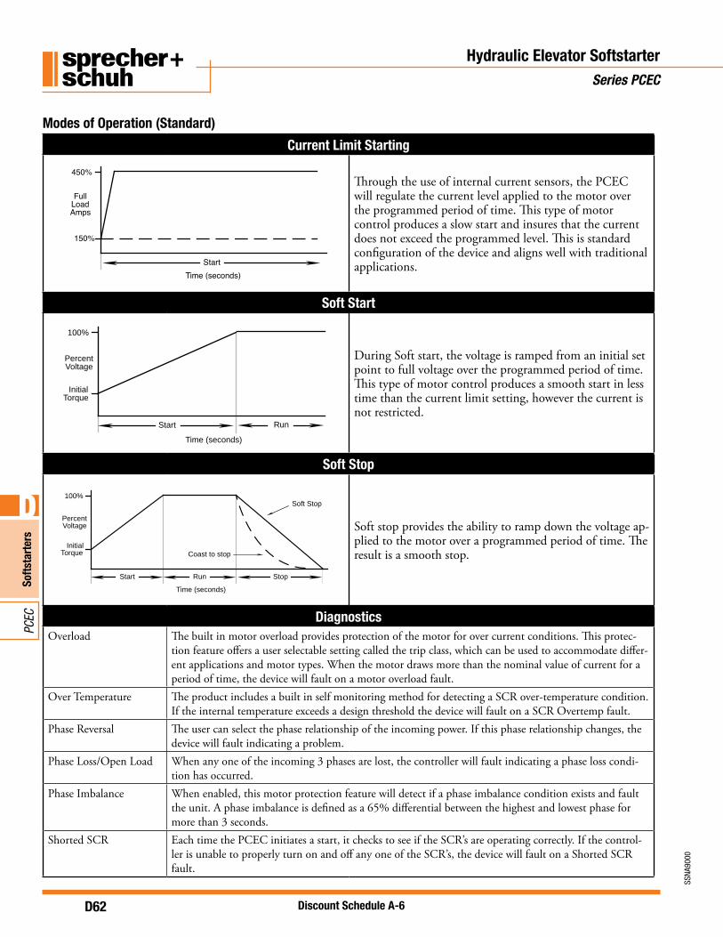
Through the use of internal current sensors, the PCEC will regulate the current level applied to the motor over the programmed period of time. This type of motor control produces a slow start and insures that the current does not exceed the programmed level. This is standard configuration of the device and aligns well with traditional applications.
Soft Start
InitialTorque
PercentVoltage
100%
Start Run
Time (seconds)
During Soft start, the voltage is ramped from an initial set point to full voltage over the programmed period of time. This type of motor control produces a smooth start in less time than the current limit setting, however the current is not restricted.
Soft Stop
InitialTorque
PercentVoltage
100%
Start Run Stop
Coast to stop
Soft Stop
Time (seconds)
Soft stop provides the ability to ramp down the voltage ap-plied to the motor over a programmed period of time. The result is a smooth stop.
DiagnosticsOverload The built in motor overload provides protection of the motor for over current conditions. This protec-
tion feature offers a user selectable setting called the trip class, which can be used to accommodate differ-ent applications and motor types. When the motor draws more than the nominal value of current for a period of time, the device will fault on a motor overload fault.
Over Temperature The product includes a built in self monitoring method for detecting a SCR over-temperature condition. If the internal temperature exceeds a design threshold the device will fault on a SCR Overtemp fault.
Phase Reversal The user can select the phase relationship of the incoming power. If this phase relationship changes, the device will fault indicating a problem.
Phase Loss/Open Load When any one of the incoming 3 phases are lost, the controller will fault indicating a phase loss condi-tion has occurred.
Phase Imbalance When enabled, this motor protection feature will detect if a phase imbalance condition exists and fault the unit. A phase imbalance is defined as a 65% differential between the highest and lowest phase for more than 3 seconds.
Shorted SCR Each time the PCEC initiates a start, it checks to see if the SCR’s are operating correctly. If the control-ler is unable to properly turn on and off any one of the SCR’s, the device will fault on a Shorted SCR fault.
Modes of Operation (Standard)
D63
SSNA
9000
Softs
tart
ers
D
PCEC
Discount Schedule A-6
PCEC Controller Panel - 120V Control Voltage ➍➏
DELTA Connected - 6 Wire Line Connected - 3 Wire ➋ With 120VAC 50/60 Hz ➌Control Voltage
Catalog Number Price
Maximum Horsepower Overload Range ➊
Maximum Horsepower Overload Range ➊200V 240V 480V 575V 200V 240V 480V 575V
➊Motor FLA must fall within the specified range to operate correctly.➋The PCEC Controller panels are shipped in the DELTA connection mode by default. LINE connection requires the power wires to be
reconfigured and DIP Switch #15 to be programmed for LINE connection mode by the customer.➌Internal fan is optional for PCEC-032…064. See page D61 to purchase separately. All other PCEC units have internal fan as standard.➍Purchase additional PCE Auxiliary Contact Blocks separately. See page D7. One Auxiliary Contact Block (one or two pole) may be
mounted on the right side of the PCE controller.➎Separate 120V or 240V single phase is required for PCEC fan operation. ➏ The PCEC Hydraulic Elevator duty rating is 80 starts per hour at 50% duty cycle (160 calls per hour). Starts per hour are based on
when the motor starts, the motor only runs on “up” calls.
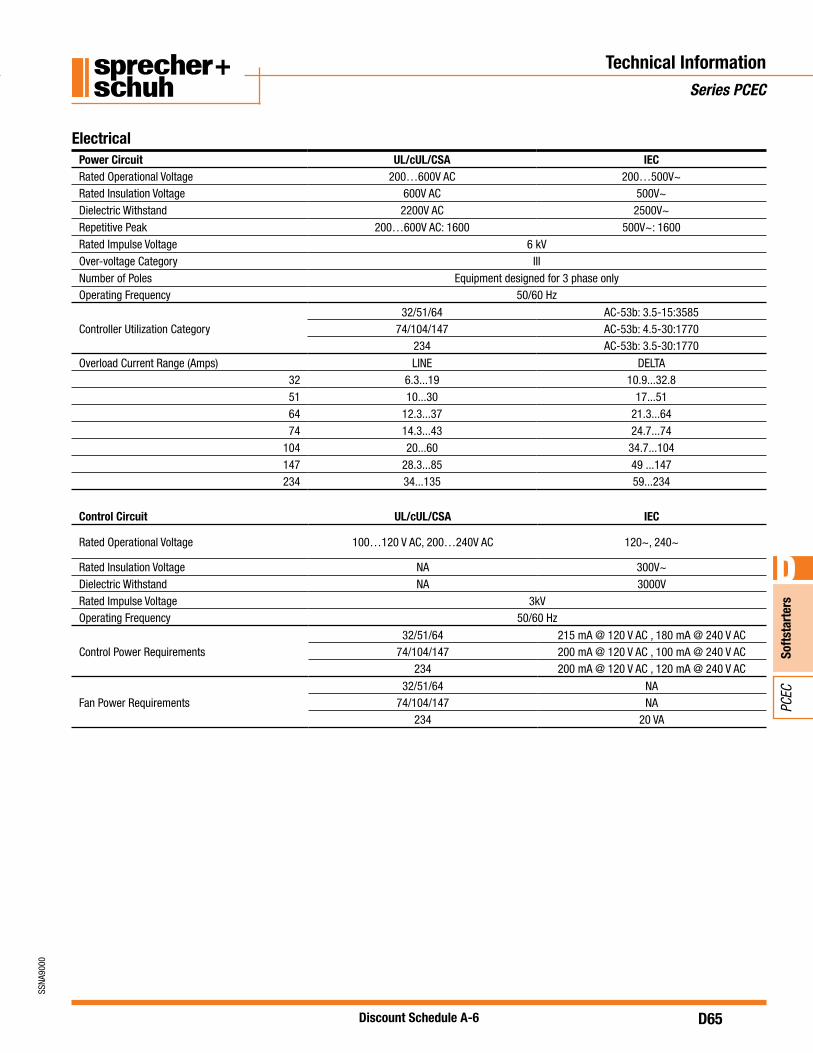
ElectricalPower Circuit UL/cUL/CSA IECRated Operational Voltage 200…600V AC 200…500V~Rated Insulation Voltage 600V AC 500V~Dielectric Withstand 2200V AC 2500V~Repetitive Peak 200…600V AC: 1600 500V~: 1600Rated Impulse Voltage 6 kVOver-voltage Category IIINumber of Poles Equipment designed for 3 phase onlyOperating Frequency 50/60 Hz
Rated Operational Voltage 100…120 V AC, 200…240V AC 120~, 240~
Rated Insulation Voltage NA 300V~Dielectric Withstand NA 3000VRated Impulse Voltage 3kVOperating Frequency 50/60 Hz
Control Power Requirements32/51/64 215 mA @ 120 V AC , 180 mA @ 240 V AC
74/104/147 200 mA @ 120 V AC , 100 mA @ 240 V AC234 200 mA @ 120 V AC , 120 mA @ 240 V AC
Fan Power Requirements32/51/64 NA
74/104/147 NA234 20 VA
Technical InformationSeries PCEC
D66
SSNA
9000
Softs
tart
ers
D
PCEC
Discount Schedule A-6
Electrical (continued)Short Circuit Performance Type 1Device Current Rating Max Fuse Size and Type Max Available Fault Rating
3270 A - RK5 5 kA125 A - K5 5 kA
51125 A - RK5 5 kA200 A - K5 10 kA
64125 A - RK5 5 kA200 A - K5 10 kA
74150 A - RK5 5 kA
250 A - J 10 kA
104200 A - RK5 5 kA
400 A - J 10 kA
147250 A - RK5 10 kA
400 A - J 10 kA
234400 A - RK5 10 kA450 A - K5 10 kA
Auxiliary Contacts (Fault and Aux#1) UL/cUL/CSA IECRated Operational Voltage 250V AC / 30V DC 250V~ / 30V DCRated Insulation Voltage 250V 250V~Rated Impulse Voltage NA 4kVDielectric Withstand 1500V AC 2000V~Operating Frequency 50/60 HzUtilization Category D300 AC-15 / DCType of Control Circuit Electromagnetic RelayNumber of Contacts 1Type of contacts Normally Open (N.O.)Type of current AC/DCRated Operational Current (Max.) 0.6 A @ 120 V~ and 0.3 A @ 240V~Conventional Thermal Current (Ith) 1 AmpMake/Break VA 432/72
MechanicalResistance to Vibration
Operational 1.0 G Peak, 0.15 mm (0.006 in) displacementNon-operational 2.5 G Peak, 0.38 mm (0.015 in) displacement
Altitude 2000 m (6560 ft)Humidity 5…95% (non-condensing)Pollution Degree 2
UL/CSA Elevator RatingsThe PCEC Softstarters are UL Listed and cUL Listed (Canadian Standards per UL 508 and CS C22.2 No. 14-95) as solid state motor controllers in File E96956. They are also UL Listed and cUL Listed per UL 508 and CAN/CSA B44.1-96 as elevator controllers in File E3125.
Technical InformationSeries PCEC
D67
SSNA
9000
Softs
tart
ers
D
PCEC
Discount Schedule A-6
Technical InformationSeries PCEC
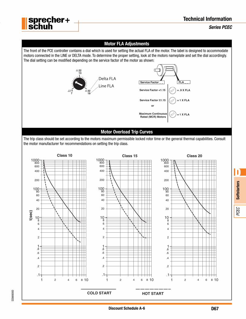
Motor FLA AdjustmentsThe front of the PCE controller contains a dial which is used for setting the actual FLA of the motor. The label is designed to accommodate motors connected in the LINE or DELTA mode. To determine the proper setting, look at the motors nameplate and set the dial accordingly. The dial setting can be modified depending on the service factor of the motor as shown:
Motor Overload Trip CurvesThe trip class should be set according to the motors maximum permissible locked rotor time or the general thermal capabilities. Consult the motor manufacturer for recommendations on setting the trip class.
)ces(t
1 102 864 1 102 864
Class 10 Class 15
1 102 864
Class 20
10
200
800600400
20
806040
2
4
.2
.8
.6
.4
100
1000
86
1
10
200
800600400
20
806040
2
4
.2
.8
.6
.4
100
1000
86
1
10
200
800600400
20
806040
2
4
.2
.1.1.1
.6
.8
.4
100
1000
86
1
COLD START HOT START
= .9 X FLA
= 1 X FLA
= 1 X FLA
FLA _ _
Service Factor <1.15
Maximum ContinuousRated (MCR) Motors
or
Service Factor _ _
Service Factor >1.15
11 7
3219
2213
Delta FLA
Line FLA
D68
SSNA
9000
Softs
tart
ers
D
PCEC
Discount Schedule A-6
Technical InformationSeries PCEC
Terminal Torque Specifications
PCE Controller Information
Controller Size Units Line Power Terminals Load Power TerminalsControl Power
Terminals
32/51/64
Wire Size
14 - 4 AWG (2.5 - 25 mm2)
14 - 6 AWG (2.5 - 16 mm2)
24 - 14 AWG (0.2 - 2.5 mm2)
Torque20 - 25 lb-in. (2.3 - 2.8 Nm)
20 - 22.5 lb-in. (2.3 - 2.6 Nm)
4.4 - 8 lb-in. (0.5 - 0.9 Nm)
74/104/147
Wire Size
14 - 3/0 AWG (2.5 - 95 mm2)
14 - 1 AWG (2.5 - 50 mm2)
24 - 14 AWG (0.2 - 2.5 mm2)
Torque100 - 110 lb-in. (11.3 - 12.4 Nm)
100 - 110 lb-in. (11.3 - 12.4 Nm)
4.4 - 8 lb-in. (0.5 - 0.9 Nm)
234
Wire Size
6 - 250 AWG (16 - 120 mm2)
6 - 250 AWG (16 - 120 mm2)
24 - 14 AWG (0.2 - 2.5 mm2)
Torque275 lb-in. (31 Nm)
275 lb-in. (31 Nm)
4.4 - 8 lb-in. (0.5 - 0.9 Nm)
Fault Contactor Information
Controller Size Units Line Power Terminals Load Power TerminalsControl Power
Terminals
32/51/64/74
Wire Size
14 - 4 AWG (2.5 - 16 mm2)
14 - 4 AWG (2.5 - 16 mm2)
16 - 12 AWG (1.5 - 6 mm2)
Torque22 - 35 lb. in. (2.5 - 4 Nm)
22 - 35 lb. in. (2.5 - 4 Nm)
9 - 13 lb. in. (1 - 2.5 Nm)
104/147
Wire Size
14 - 1 AWG (2.5 - 35 mm2)
14 - 1 AWG (2.5 - 35 mm2)
16 - 12 AWG (1.5 - 6 mm2)
Torque31 - 53 lb. in. (3.5 - 6 Nm)
31 - 53 lb. in. (3.5 - 6 Nm)
9 - 13 lb. in. (1 - 2.5 Nm)
234
Wire Size
6 - 300 AWG (16 - 150 mm2)
6 - 300 AWG (16 - 150 mm2)
2x 16…12 AWG (2x 1…4 mm2)
Torque250 lb-in. (28 Nm)
250 lb-in. (28 Nm)
12 - 20 lb-in. (1.4 - 2.3 Nm)
D69
SSNA
9000
Softs
tart
ers
D
PCEC
Discount Schedule A-6
Wiring DiagramsSeries PCEC
DELTA Connection Diagrams, Power, and Motor Wiring
3
2
1
6
4
5
INCOMING LINES
L1 L2 L3
T3/6
PCE
L3/5(1)(L1)
(2)(T2)
FC
(T6) (T3)
MOTOR[6] [3]
L1 L2 L3
T6 T4 T5T1 T2 T3
INCOMING LINE CONNECTIONS
(6)(T3)
(5)(L3)
FC
(T2)
(T5)
L2/3
PCE
T2/4
MO
TOR
[2]
[5]
(4)
(T2)
(3)
(L2)
FC
(T1)
(T4)
L1/1
PCE
T1/2
MO
TOR
[1]
[4]
INCOMING LINES
L1 L2 L3
T3/6
PCE
L3/5(1)(L1)
(2)(T2)
FC
(T6) (T3)
MOTOR
[12]
(6)(T3)
(5)(L3)
FC
L2/3
PCE
T2/4
(4)
(T2)
(3)
(L2)
FC
(T1)
(T4)
L1/1
PCE
T1/2
MO
TOR
[1]
[4]
INCOMING LINES
L1 L2 L3
T3/6
PCE
L3/5(1)(L1)
(2)(T2)
FC
(T6) (T3)
MOTOR[6] [3]
(6)(T3)
(5)(L3)
FC
(T2)
(T5)
L2/3
PCE
T2/4
MO
TOR
[2]
[5]
(4)
(T2)
(3)
(L2)
FC
(T1)
(T4)
L1/1
PCE
T1/2
MO
TOR
[1]
[4]
T6 T4 T5T1 T2 T3
L1 L2 L3
MOTOR
928
12410
T6 T4 T5T1 T2 T3
MOTOR
12 LEAD 230V LOW VOLTAGE MOTOR CONNECTIONSSTARTER
TERMINALST1 T2 T3 T6 T4 T5 JUMPER
MOTOR TERMINALS
1&7 2&8 3&9 6&12 4&10 5&11 N/A
STARTER TERMINALS
T1 T2 T3 T6 T4 T5 JUMPER
MOTOR TERMINALS
1&7 2&8 3&9 6&12 4&10 5&11 N/A
6 LEAD MOTOR CONNECTIONS
STARTER TERMINALS
T1 T2 T3 T6 T4 T5 JUMPER
MOTOR TERMINALS
1 2 3 12 10 114&7 5&8 6&9
12 LEAD 460V HIGH VOLTAGE MOTOR CONNECTIONS
[2]
[5]
[6] [3]
[1]
[4]
[2]
[5]
[6] [3]
[1]
[4]
[7]
[10] [8]
[11]
[12] [9]
[7]
[10]
[8]
[11]
[12] [9]
[7]
[10] (T2)
(T5)
MO
TOR
[2][5]
[8][11]
[9] [6] [3]
[2][5]
[8][11]
[1]
[4]
[7]
[10]
[12] [9] [6] [3]
3 6
1 57 11
2
1
9
10
11
4
T6 T4 T5T1 T2 T3
MOTOR
3 12
6 78 5
FC(A2) (A1)
PCE CONTROL WIRES
IN1 IN2 98 13 1497A2A1
13
4
21
IN1A1 A2 1413IN2 9897
1/L1 3/L2 5/L3
2/T1 4/T2 6/T3
PCE
1/L1 3/L2 5/L3
T6 T4 T5
FC
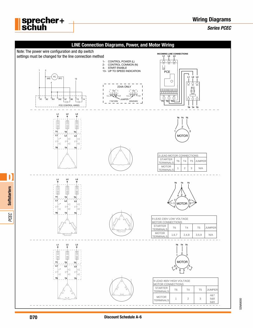
1- CONTROL POWER (L)2- CONTROL COMMON (N)4- START ENABLE13- UP TO SPEED INDICATION
FAN41 2 3
21
234A ONLY
110/120V
FAN41 2 3
21
220/240VJUMPER
D70
SSNA
9000
Softs
tart
ers
D
PCEC
Discount Schedule A-6
Wiring DiagramsSeries PCEC
LINE Connection Diagrams, Power, and Motor Wiring
T6 T4 T5
T1 T2 T3
INCOMING LINE CONNECTIONS
L1 L2 L3FC(A2) (A1)
PCE CONTROL WIRES
IN1 IN2 98 13 1497A2A1
13
4
21
IN1A1 A2 1413IN2 9897
1/L1 3/L2 5/L3
2/T1 4/T2 6/T3
PCE
1/L1 3/L2 5/L3
T6 T4 T5
FC
L1 L2 L3
1- CONTROL POWER (L)2- CONTROL COMMON (N)4- START ENABLE13- UP TO SPEED INDICATION
FAN41 2 3
21
234A ONLY
110/120V
FAN41 2 3
21
220/240VJUMPER
32
1
T6 T4 T5
MOTOR
6
47
8
T6 T4 T5
MOTOR1
2
39
5
21
9 4
T6 T4 T5
MOTOR
3
6 78 5
1T2/
L1/1
T2/4
L2/3
T3/6
L3/5
) 1() 1L(
(2)
(T1)
FC
) 3( () 2L
(4)
(T2)
FC
(5)
() 3L
(6)
(T3)
FC
L1 L2 L3
T1 T2 T3
T6 T4 T5
L1 L2 L3
[3]
[2]
[1]
T1/2
L11/
T2/4
L2/3
T3/6
L3/5
) 1() 1L(
(2)
(T1)
CF
) 3( () 2L
(4)
(T2)
CF
(5)
() 3L
(6)
(T3)
CF
L1 L2 L3
T1 T2 T3
T6 T4 T5
L1 L2 L3
[3]
[2]
[1]
T1/2
L11/
T2/4
L2/3
T3/6
L3/5
) 1() 1L(
(2)
(T1)
CF
) 3( () 2L
(4)
(T2)
CF
(5)
() 3L
(6)
(T3)
CF
L1 L2 L3
T1 T2 T3
T6 T4 T5
L1 L2 L3
[3]
[2]
[1]
[3]
[2]
[1]
3 LEAD MOTOR CONNECTIONS
STARTERTERMINALS
T6 T4 T5 JUMPER
MOTORTERMINALS
1 2 3 N/A
[5]
[8]
[7]
[4]
[6][9]
[3]
[2]
[1]
[5]
[8]
[7]
[4]
[6]
[9]
STARTERTERMINALS
T6 T4 T5 JUMPER
MOTORTERMINALS
1,6,7 2,4,8 3,5,9 N/A
9 LEAD 230V LOW VOLTAGEMOTOR CONNECTIONS
[4]
[7] [5]
[8]
[9] [6]
STARTERTERMINALS
T6 T4 T5 JUMPER
MOTORTERMINALS
1 2 34&75&86&9
9 LEAD 460V HIGH VOLTAGEMOTOR CONNECTIONS
[3]
[2]
[1]
[5][8]
[7]
[4]
[6][9]
Note: The power wire configuration and dip switch settings must be changed for the line connection method
D71
SSNA
9000
Softs
tart
ers
D
PCEC
Discount Schedule A-6
Wiring DiagramsSeries PCEC
DELTA Connected Controller - Typical Control Wiring LINE Connected Controller - Typical Control Wiring
PCE CONTROL TERMINALS
IN1 IN2 98 13 1497A2A1
FC
MOTOR1
H3 H2
H1 H4
OVLD / FAULT AUX #1(UP TO SPEED)
GND
UP TO SPEEDINDICATION
E- STOP
START
X1 X2
1
1
ENABLE
1
1 CUSTOMER SUPPLIED
FC
FC
FC
TRANS.
A1 A2
L3 T5
L2 T4
L1 T6
T1/2L1/1
T2/4L2/3
T3/6L3/5
PCE(POWER CONNECTIONS)
SCPD
PCE CONTROL TERMINALS
IN1 IN2 98 13 1497A2A1
FC
T1/2L1/1
T2/4L2/3
T3/6L3/5
FC
FC
FC
MOTOR
PCE(POWER CONNECTIONS)
1
H3 H2
H1 H4
OVLD / FAULT AUX #1(UP TO SPEED)
GND
UP TO SPEEDINDICATION
E- STOP
START
X1 X2
1
1
ENABLE
1
1 CUSTOMER SUPPLIED
TRANS.
A1 A2
L1 T6
L2 T4
L3 T5
SCPD
➊ When (A1)(A2) control power is applied, (97)(98) contact closes instantaneously and opens when the PCE detects an overload or fault condition, or when control power is removed.
➊
➊
D72
SSNA
9000
Softs
tart
ers
D
PCEC
Discount Schedule A-6
PCEC Hydraulic Elevator Softstarter
DimensionsSeries PCEC
Controller Size Units A (Width) B (Height) C (Depth) D E Hole Dim - 4x Approx. Weight