40
PCI-8213/8214 4-Port / 2-Port PCI Ethernet Controller User’s Guide Recycled Paper

PCI-8213/8214 4-Port / 2-Port PCI Ethernet Controller
User’s Guide
Recycled Paper


©Copyright 2002 ADLINK Technology Inc.
All Rights Reserved.
Manual Rev. 1.0: June 2002
Part No : 50-13028-110
The information in this document is subject to change without prior notice in order to improve reliability, design and function and does not represent a commitment on the part of the manufacturer.
In no event will the manufacturer be liable for direct, indirect, special, incidental, or consequential damages arising out of the use or inability to use the product or documentation, even if advised of the possibility of such damages.
This document contains proprietary information protected by copyright. All rights are reserved. No part of this manual may be reproduced by any mechanical, electronic, or other means in any form without prior written permission of the manufacturer.
Trademarks
Other product names mentioned herein are used for identification purposes only and may be trademarks and/or registered trademarks of their respective companies.

Getting service from ADLINK Customer Satisfaction is always the most important thing for ADLINK Tech Inc. If you need any help or service, please contact us and get it.
ADLINK Technology Inc.
Web Site http://www.adlinktech.com
Sales & Service
NuDAQ [email protected] Automation [email protected] NuIPC [email protected]
Technical Support
NuPRO / EBC [email protected] TEL +886-2-82265877 FAX +886-2-82265717
Address 9F, No. 166, Jian Yi Road, Chungho City, Taipei, 235 Taiwan Please inform or FAX us of your detailed information for a prompt, satisfactory and constant service.
Detailed Company Information Company/Organization Contact Person E-mail Address Address Country TEL FAX Web Site
Questions Product Model
¨OSssss
¨Computer Brand:
Environment to Use
¨M/B: ¨CPU: ¨Chipset: ¨Bios: ¨Video Card: ¨Network Interface Card: ¨Other:
Challenge Description
Suggestions to ADLINK

Table of Contents • i
Table of Contents How to use this guide .........................................................iii
Chapter 1 Introduction........................................................ 1
1.1 Ethernet ...........................................................................1 1.1.1 Fast Ethernet.....................................................................................1 1.1.2 Connect the Network Cable............................................................2 1.1.3 Pin-definition of RJ45 Connector....................................................2
1.2 Drivers on ADLINK CD......................................................3
Chapter 2 PCI-8213 .............................................................. 4
2.1 Introduction ......................................................................4 2.2 Specifications ...................................................................4 2.3 Installation........................................................................6 2.4 Jumper Setting .................................................................6 2.5 PCI-8213 Front Panel .......................................................7 2.6 Extra Display Connector....................................................8 2.7 PXE Function ...................................................................9
Chapter 3 PCI-8214 ............................................................10
3.1 Introduction .................................................................... 10 3.2 Specifications ................................................................. 10 3.3 Installation...................................................................... 12 3.4 Jumper Setting ............................................................... 13 3.5 PCI-8214 Front Panel ..................................................... 13 3.6 Extra Display Connector.................................................. 14 3.7 PXE Function ................................................................. 15
Chapter 4 82559 Driver Installation ...............................16
4.1 Software and Drivers Support .......................................... 16 4.2 Driver Installation on Windows 2000 ................................ 17 4.3 Driver Installation on Windows 98 (SE & ME) ................... 18 4.4 Driver Installation on Windows NT ................................... 19 4.5 Driver Installation on Red Hat Linux ................................. 20
Chapter 5 Bypass and WDT............................................21
5.1 Bypass Operation ........................................................... 21 5.1.1 Block Diagram ................................................................................ 21
ii • Table of Contents
5.1.2 Communication States.................................................................. 22 5.1.3 WDT Test Utilities .......................................................................... 22 5.1.4 WDT and State Change................................................................ 22
5.2 WDT control ................................................................... 25 5.2.1 WDT control.................................................................................... 25 5.2.2 WDT Time-out Value..................................................................... 25 5.2.3 Programming information of the WDT........................................ 26
5.3 DOS Test Utility.............................................................. 28 5.4 WDT DLL for Windows NT & 2000 ................................... 28 5.5 WDT Library for Linux ..................................................... 29
Warranty Policy ..................................................................31

How to Use This Guide • iii
How to use this guide
This manual is to help you use PCI-821X series modules. The briefs contents are as following:
Chapter 1, Introduction gives an overview of the Ethernet. The detail information of each product is list in Chapter 2 to Chapter 4.
Chapter 2, PCI-8213 gives detail information of this product.
Chapter 3, PCI-8214 gives detail information of this product.
Chapter 4, 82559 Driver Installation gives detail information of NIC driver installation for the PCI-8213 and PCI-8214 products.
Chapter 5, WDT and Bypass gives the details of the bypass function and how to control the WDT.

Introduction • 1
1
Introduction
This users manual is used for PCI-8213 and PCI-8214 products based on standard universal PCI short card. The products include:
PCI-8213: 4 ports of 10 Base-T / 100 Base-TX Fast Ethernet PCI-8214: 2 ports of 10 Base-T / 100 Base-TX Fast Ethernet Please refer the Chapter 2 and Chapter 3 for detail information of those products. In the following sections, we introduce the basic information about Ethernet.
1.1 Ethernet
1.1.1 Fast Ethernet
Fast Ethernet is a network technology specified by IEEE Standard 802.3u. It extends the traditional 10Mbps Ethernet technology to achieve 100Mbps transmission and reception, while retaining the same CSMA/CA Ethernet protocol. Thus while Fast Ethernet provides a tenfold increase in network capacity, it is completely compatible with traditional 10Mbps Ethernet network facilities.
The compatibility is the key to easily and efficiently upgrade to100Mbps in your network areas while greater bandwidth is needed. Upgrading selected areas to Fast Ethernet does not require hardware or software changes in network areas where traditional 10Mbps Ethernet is providing good service. For upgrading existing Ethernet installations to 100Mbps, and especially for selectively upgrading areas needing upgrade, Fast Ethernet is the clear choice in terms of cost-effectiveness, as well as convenience and smoothness in transition.
Fast Ethernet comprises of two subtypes: 100Base-T4 and 100Base-TX.
2 • Introduction
100Base-T4 Fast Ethernet can utilize existing Category 5 cabling, but doesn’t provide full duplex operation. Full duplex 100Base-TX operation allows simultaneous transmission and reception, both at 100Mbps, thus providing service potentially equal to 200Mbps half-duplex service.
1.1.2 Connect the Network Cable
Category 5 UTP cable qualifies for both, the Fast Ethernet and Ethernet, cabling rules. The maximum length of any single cable run between any station and its supporting Hub is 100 meters. The maximum length of a cable joining two Hubs is 10m in general, but is 100m when both Hubs qualify as Ethernet class 2 Repeaters. However, these cables run may need to be shorter than the given individual maxim um lengths because their maximum aggregated cable run between any two stations is 205m.
Connecting for 100Mbps Ethernet Category 5 UTP cable is required for fast Ethernet operation. The maximum cable run between the PCI-8213/8214 and the supporting Hub is 100 meters. The cable must be straight (not a crossover cable) with an RJ-45 plug at each end. Make the network connection by plugging one end of the cable into the RJ-45 jack of the PCI-8213/8214, and the other end into a port of the supporting Hub.
Connecting for 10Mbps Ethernet Category 3, Category 4, and Category 5 UTP cable, as well as EIA/TIA-568 100-0hm STP cable, all qualify under Ethernet cabling rules. The maximum cable run between the PCI-8213/8214 and the supporting Hub is 100 meters. The cable must be straight (not a crossover cable) with RJ-45 connector at each end. To connect the network is via plugging one end of the cable into the RJ-45 jack of the PCI-8213/8214 and the other end into a port of the supporting Hub.
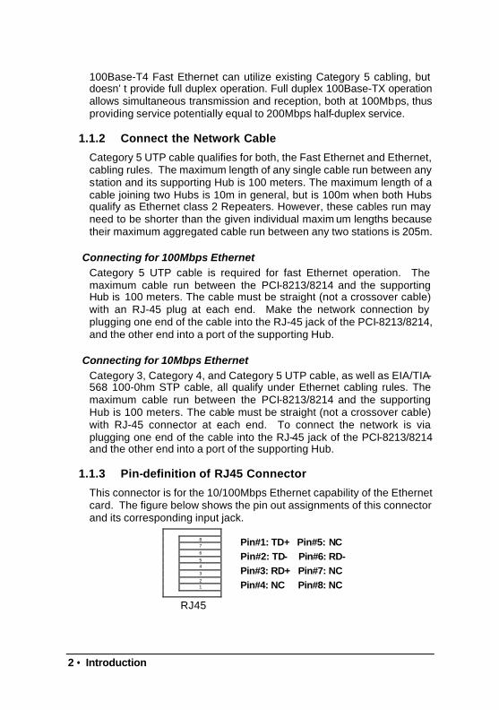
1.1.3 Pin-definition of RJ45 Connector
This connector is for the 10/100Mbps Ethernet capability of the Ethernet card. The figure below shows the pin out assignments of this connector and its corresponding input jack.
8 7
6
5 4
3
2
1
RJ45
Pin#1: TD+ Pin#5: NC Pin#2: TD- Pin#6: RD- Pin#3: RD+ Pin#7: NC Pin#4: NC Pin#8: NC
Introduction • 3
1.2 Drivers on ADLINK CD
To install the drivers and utility for the PCI-8213 / 8214 product, please refer the detail installation information from the Chapter 4. We provide the basic information in this manual, however, for more detail installation information, such as non-Windows OS installation, please refer the extensive explanation inside the ADLINK CD. We put the LAN driver in the following directory:
LAN driver of 82559 Chip\CHIPDRV\LAN\100pdisk
Due to the Windows NT is a none plug-and-play OS, we remind you some tips for installing the Windows NT here:
1. We suggest that installing the newest update version of service pack after installing LAN driver.
2. We suggest installing any other driver before installing service pack. Please make sure your service pack does support AGP, thus service pack 6.0a is recommended.
3. Once your NT booting procedure is warning, please check the Event Viewer to make sure what is the real problem. If Windows NT is showing any warning messages which could not be solved, we suggest to re-install Windows NT, and install all drivers in different sequence again.
4 • PCI-8213
2
PCI-8213
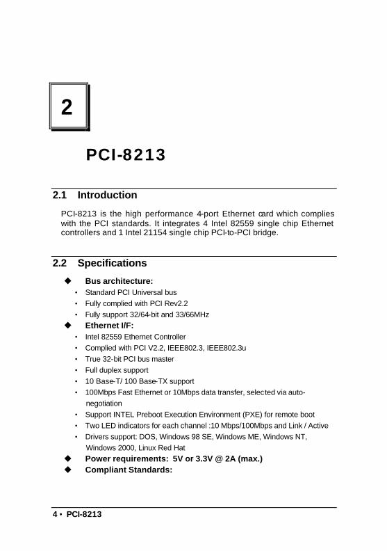
2.1 Introduction
PCI-8213 is the high performance 4-port Ethernet card which complies with the PCI standards. It integrates 4 Intel 82559 single chip Ethernet controllers and 1 Intel 21154 single chip PCI-to-PCI bridge.
2.2 Specifications
u Bus architecture: • Standard PCI Universal bus • Fully complied with PCI Rev2.2 • Fully support 32/64-bit and 33/66MHz
u Ethernet I/F: • Intel 82559 Ethernet Controller • Complied with PCI V2.2, IEEE802.3, IEEE802.3u • True 32-bit PCI bus master • Full duplex support • 10 Base-T/ 100 Base-TX support • 100Mbps Fast Ethernet or 10Mbps data transfer, selected via auto-
negotiation • Support INTEL Preboot Execution Environment (PXE) for remote boot • Two LED indicators for each channel :10 Mbps/100Mbps and Link / Active • Drivers support: DOS, Windows 98 SE, Windows ME, Windows NT,
Windows 2000, Linux Red Hat u Power requirements: 5V or 3.3V @ 2A (max.) u Compliant Standards:

PCI-8213 • 5
• CE Test According to: EMI Test : European Standard EN 55022 Class B Harmonic Test : European Standard EN 61 000-3-2 Voltage fluctuations Test : European Standard EN 61 000-3-3 EMS Test : European Standard EN 50 082-1:1997
• FCC Test According to : Standard for Methods of Measurement ANSI C63.4 – 1992 Test in Compliance with CISPR PUB. 22 and FCC Part 15
u Environment: • Operating Temperature: 0 to 60oC • Storage Temperature: -20 to 80oC • Humidity: 10%~90% non condensing
u Dimension: • Standard PCI half-sized card form factor

6 • PCI-8213
2.3 Installation
After unpacking the box, please check if the package contains the following items. If you discover any damage or any item missing, please contact with your dealer.
PCI-8213: Standard PCI short card board ADLINK CD This manual
You may follow the following steps to install this card into your system.
1. Read this Manual 2. Check the PCB if there is any damage on it 3. Setup the jumper if necessary 4. Install the board into your system 5. Prepare to install the software drivers, you may need to prepare a
floppy diskette to pre-copy the drivers from ADLINK CD if you install drivers by a FDD.
6. Install driver 7. Connect the Ethernet cable to check the board function.
2.4 Jumper Setting
The PCI-8213 supports remote boot via PREBOOT EXECUTION ENVIRONMENT (PXE) function by installing a boot ROM. The boot ROM is default installation but disable. The only jumper on the PCI-8213 is used to enable or disable the boot ROM.
JP2: Boot Rom enable & disable setting
Default Setting JP2 Disable BOOT
ROM Enable BOOT
ROM
Jumper Pin No. 1 - 2 2 - 3
PCI-8213 • 7
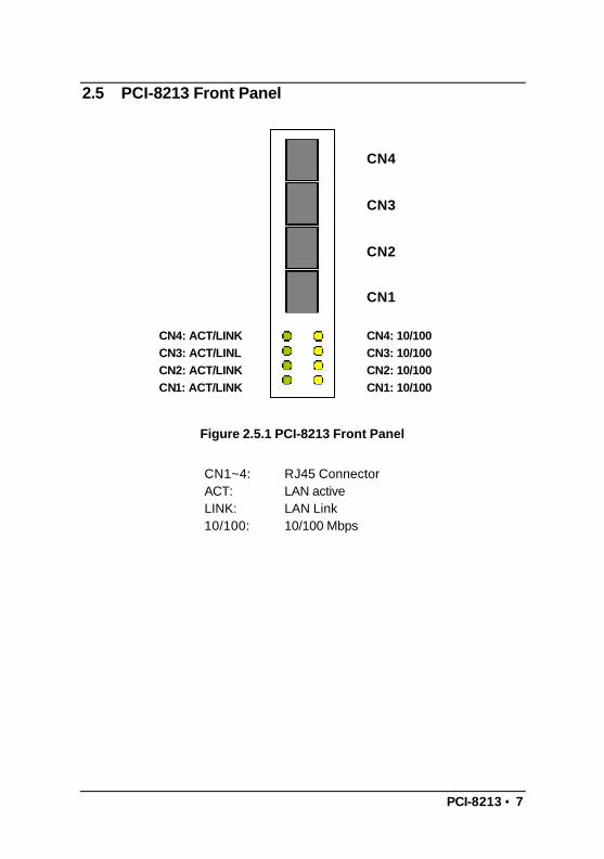
2.5 PCI-8213 Front Panel
Figure 2.5.1 PCI-8213 Front Panel
CN1~4: RJ45 Connector ACT: LAN active LINK: LAN Link 10/100: 10/100 Mbps
CN4: ACT/LINK CN3: ACT/LINL CN2: ACT/LINK CN1: ACT/LINK
CN4: 10/100 CN3: 10/100 CN2: 10/100 CN1: 10/100
CN4
CN3
CN2
CN1

8 • PCI-8213
2.6 Extra Display Connector
Figure 2.6.1 Extra Display Connector Pin Assignment
JP4
JP3
GROUND
SPEED LED
ACT LED
RESERVE
RESERVE
CH1
CH2
CH4
CH3
PCI-8213 • 9
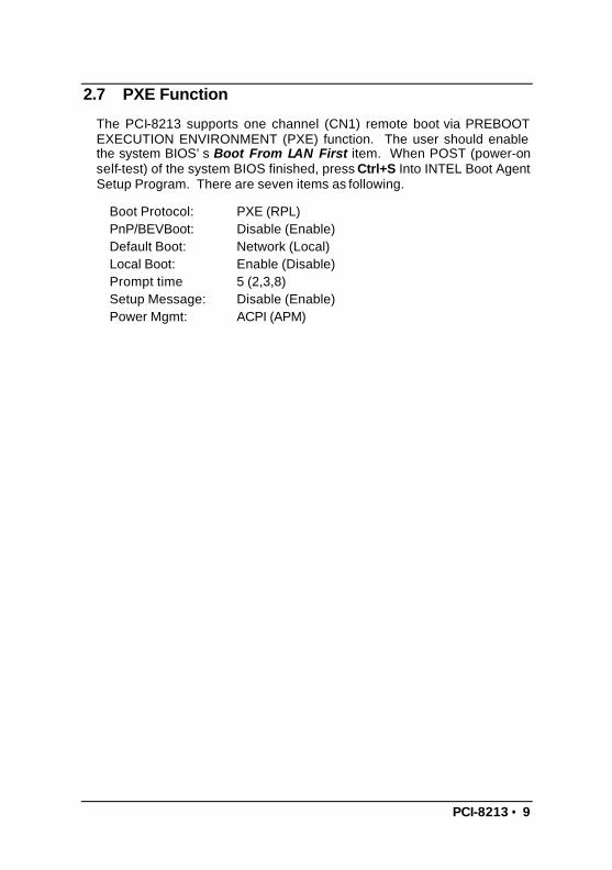
2.7 PXE Function
The PCI-8213 supports one channel (CN1) remote boot via PREBOOT EXECUTION ENVIRONMENT (PXE) function. The user should enable the system BIOS’s Boot From LAN First item. When POST (power-on self-test) of the system BIOS finished, press Ctrl+S Into INTEL Boot Agent Setup Program. There are seven items as following.
Boot Protocol: PXE (RPL) PnP/BEVBoot: Disable (Enable) Default Boot: Network (Local) Local Boot: Enable (Disable) Prompt time 5 (2,3,8) Setup Message: Disable (Enable) Power Mgmt: ACPI (APM)

10 • PCI-8214
3
PCI-8214
3.1 Introduction
PCI-8214 is the high performance 2-port Ethernet card, which complies with the PCI standards. It integrates 2 Intel 82559 single chip Ethernet controllers and one Intel 21154 single chip PCI-to-PCI bridge. PCI-8214 has the ability of connecting two channels while the system is halted or software is down when WDT function is active.
3.2 Specifications
u Bus architecture: • Standard PCI Universal bus • Fully complied with PCI Rev2.2 • Fully support 32/64-bit and 33/66MHz
u Ethernet I/F: • Intel 82559 Ethernet Controller • Complied with PCI V2.2, IEEE802.3, IEEE802.3u • True 32-bit PCI bus master • Full duplex support • 10 Base-T/ 100 Base-TX support • 100Mbps Fast Ethernet or 10Mbps data transfer, selected via auto-
negotiation • Support INTEL Preboot Execution Environment (PXE) for remote boot • Two LED indicators for each channel :10 Mbps/100Mbps and Link / Active • Drivers support: DOS, Windows 98 SE, Windows ME, Windows NT,
Windows2000, Linux

PCI-8214 • 11
u Power: • Power Requirement: 5V or 3.3V @ 1.2A (maximum)
u Compliant Standards:
• CE Test According to: EMI Test: European Standard EN 55022 Class B Harmonic Test: European Standard EN 61 000-3-2 Voltage fluctuations Test: European Standard EN 61 000-3-3 EMS Test: European Standard EN 50 082-1:1997
• FCC Test According to: Standard for Methods of Measurement ANSI C63.4 – 1992
• Test in Compliance with CISPR PUB. 22 and FCC Part 15 u Environment:
• Operating Temperature: 0 to 60oC • Storage Temperature: -20 to 80oC • Humidity: 10%~90% non condensing
u Dimension: • Standard PCI half-sized card form factor
12 • PCI-8214
3.3 Installation
After unpacking the box, please check if the package contains the following items. If you discover any damage or any item missing, please contact with your dealer.
PCI-8214 card ADLINK CD This manual
You may follow the following steps to install this card into your system.
1. Read this Manual 2. Check the PCB if there is any damage on it 3. Setup the jumper if necessary 4. Install the board into your system 5. Prepare to install the software drivers, you may need to prepare a
floppy diskette to pre-copy the drivers from ADLINK CD if you install drivers by a FDD.
6. Install driver 7. Connect the Ethernet cable to check the board function. 8. Setup WDT function program when bypass ability is needed. WDT
program provided is only used in NT environment.

PCI-8214 • 13
3.4 Jumper Setting
The PCI-8214 supports remote boot via PREBOOT EXECUTION ENVIRONMENT (PXE) function by installing a boot ROM. The boot ROM is default installation but disable. The only jumper on the PCI-8214 is used to enable or disable the boot ROM.
JP2: Boot Rom enable & disable setting
Default Setting JP2 Disable BOOT
ROM Enable BOOT
ROM
Jumper Pin No. 1 - 2 2 – 3
3.5 PCI-8214 Front Panel
Figure 2.5.1 Front Panel of PCI-8214
LED Status Description Blinking Bypass is active
Light 100 Mbps 10/100 Dark 10 Mbps
Blinking Data transmission is active Light LAN Link ACT Dark LAN disconnect
CN2: ACT/LINK CN1: ACT/LINK
CN2: 10/100 CN1: 10/100
CN2
CN1
14 • PCI-8214
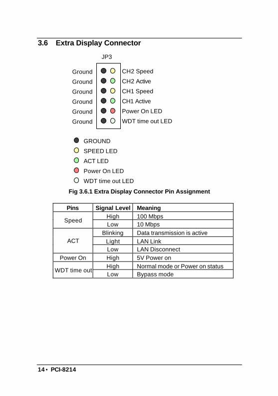
3.6 Extra Display Connector
Fig 3.6.1 Extra Display Connector Pin Assignment
Pins Signal Level Meaning High 100 Mbps
Speed Low 10 Mbps
Blinking Data transmission is active Light LAN Link ACT Low LAN Disconnect
Power On High 5V Power on High Normal mode or Power on status
WDT time out Low Bypass mode
GROUND
SPEED LED
ACT LED
Power On LED
WDT time out LED
JP3
CH2 Speed
CH2 Active
CH1 Speed
CH1 Active
Power On LED
WDT time out LED
Ground
Ground
Ground
Ground
Ground
Ground
PCI-8214 • 15
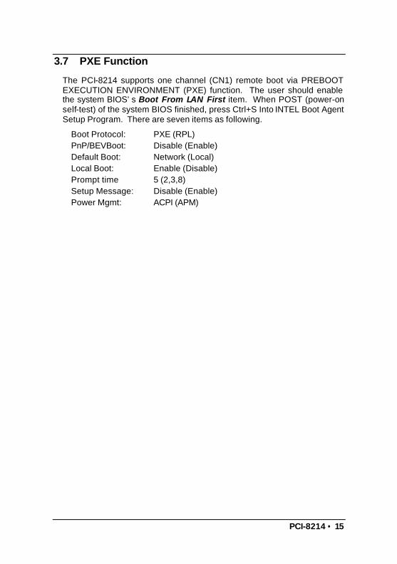
3.7 PXE Function
The PCI-8214 supports one channel (CN1) remote boot via PREBOOT EXECUTION ENVIRONMENT (PXE) function. The user should enable the system BIOS’s Boot From LAN First item. When POST (power-on self-test) of the system BIOS finished, press Ctrl+S Into INTEL Boot Agent Setup Program. There are seven items as following.
Boot Protocol: PXE (RPL) PnP/BEVBoot: Disable (Enable) Default Boot: Network (Local) Local Boot: Enable (Disable) Prompt time 5 (2,3,8) Setup Message: Disable (Enable) Power Mgmt: ACPI (APM)

16 • 82559 Driver Installation
4
82559 Driver Installation
This chapter describes LAN driver installation for the onboard Ethernet controller Intel 82559. The relative drivers are under the following ADLINK CD directory: X:\CHIPDRV\LAN\100pdisk, where X: is the location of the CD-ROM drive.
4.1 Software and Drivers Support
The 82559 drivers support the following OS or platforms:
Windows 95, Windows 98, Windows 2000, Windows NT Novell Netware, DOS Setup for Novell NetWare DOS UNIX, OS2, Linux
All the above drivers are included in the ADLINK CD. In the following section, we will describe the driver installation for Windows 98, Windows 2000, Windows NT and Linux. For the driver installation of other OS, please refer the read-me file inside the CD.
82559 Driver Installation • 17
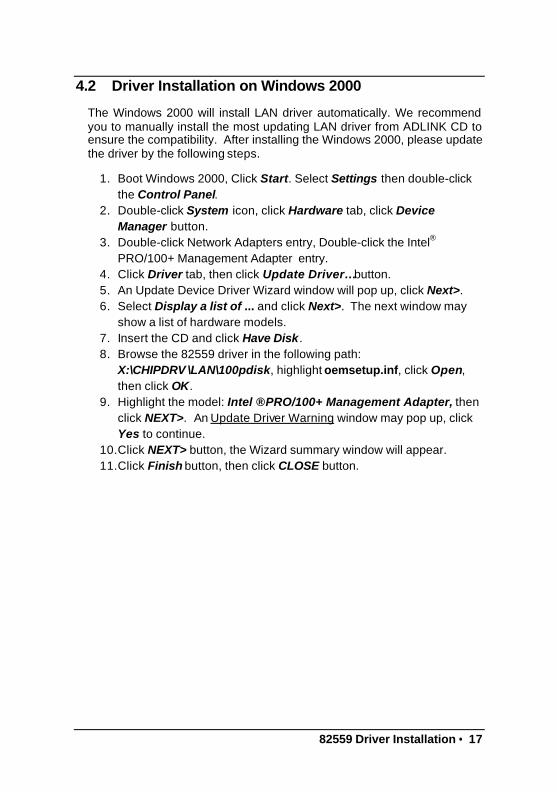
4.2 Driver Installation on Windows 2000
The Windows 2000 will install LAN driver automatically. We recommend you to manually install the most updating LAN driver from ADLINK CD to ensure the compatibility. After installing the Windows 2000, please update the driver by the following steps.
1. Boot Windows 2000, Click Start. Select Settings then double-click the Control Panel.
2. Double-click System icon, click Hardware tab, click Device Manager button.
3. Double-click Network Adapters entry, Double-click the Intel®
PRO/100+ Management Adapter entry. 4. Click Driver tab, then click Update Driver… button. 5. An Update Device Driver Wizard window will pop up, click Next>. 6. Select Display a list of ... and click Next>. The next window may
show a list of hardware models. 7. Insert the CD and click Have Disk. 8. Browse the 82559 driver in the following path:
X:\CHIPDRV \LAN\100pdisk, highlight oemsetup.inf, click Open, then click OK.
9. Highlight the model: Intel ® PRO/100+ Management Adapter, then click NEXT>. An Update Driver Warning window may pop up, click Yes to continue.
10. Click NEXT> button, the Wizard summary window will appear. 11. Click Finish button, then click CLOSE button.

18 • 82559 Driver Installation
4.3 Driver Installation on Windows 98 (SE & ME)
The Windows 98 will install the LAN driver automatically. We recommend you to manually update the LAN driver from ADLINK CD to ensure the compatibility. After setuping Windows 98, please update the driver through the following steps.
1. Boot Windows 98, Click Start. Select Settings then double-click the Control Panel.
2. Double-click on the System icon, click on the Device Manager tab. 3. Either Double-click on the Network Adapters entry, select the Intel
8255x-based PCI Ethernet Adapter (10/100) entry. Click the Properties button.
4. Click on the Driver button, then click Update Driver… button. 5. Update Device Driver Wizard starts, click NEXT 6. Select Display a list of ... and click NEXT. The next window allows
the user to specify a specific path. Insert the CD and click Have Disk.
7. Browse the 82559 driver in the following path: X:\CHIPDRV \LAN\100pdisk, highlight net82557.inf, click OK. The Update Wizard displays the message that it has found the driver. Click OK again to update the driver. Note: Windows 98 may ask you to insert the original Windows 98 CD to install the LAN protocols.
8. Click NEXT button, then the Wizard summary window appears. 9. Click Finish button, then restart the computer to activate the new
driver.

82559 Driver Installation • 19
4.4 Driver Installation on Windows NT
Before installing LAN driver on Windows NT, please copy the files of LAN driver in the CD to your hard disk. You may copy the relative NT drivers in the directory below.
X:\CHIPDRV\LAN\100pdisk
where X is the CD-ROM drive.
After booting, Windows NT may detect the hardware of the LAN card and ask to install a LAN driver from its own library of drivers. We recommend you to manually update the LAN driver on ADLINK CD to ensure the compatibility. Please update the driver through the following steps.
1. From the Control Panel, double-click the Network icon, a Network Configuration window will pop up.
2. Click ADD button, Select Network Adapter window will pop up, there are several adapter models on the list.
3. Click Have Disk and type in the complete path of the directory contained LAN driver you saved earlier.
4. A Select OEM Option window pop up, click OK, then click Next>. 5. Select necessary Network Protocols, click Next>. 6. Select necessary Network Services, click Next>. 7. Click Next> until Windows NT Setup dialog box pop up. Type in
X:\i386 in the dialog box, then insert the original Windows NT CD, click Continue.
8. Then click OK until the setup is completed. 9. Restart the computer.

20 • 82559 Driver Installation
4.5 Driver Installation on Red Hat Linux
The 82559 source code has been included in Red Hat 6.2, 7.0, 7.1 and 7.2 Linux kernel. So what you need to do is plug your card in and boot Red Hat, then the driver will be automatically installed.

Bypass and WDT • 21
5
Bypass and WDT
The bypass function on PCI-8214 in used to link (or short) two independent Ethernet ports when user’s application software halt or when power is off.
5.1 Bypass Operation
5.1.1 Block Diagram
The following diagram shows the operation of bypass on PCI-8214:
82559Ethemet #1
82559Ethernet #2
BypassRelays
WDTRelayDriver
Intel 21154
PCI-to-PCI
bridge chip
( 64 or 32-bit )
GPIO0
GPIO1
GPIO2
GPIO3
Normal StateRelays are "Energized".
SW1
JP4~7
Time out value
Power on default
PCI BUS 32-bit
32-bit
32-bitor64-bit
PCI Slot
22 • Bypass and WDT
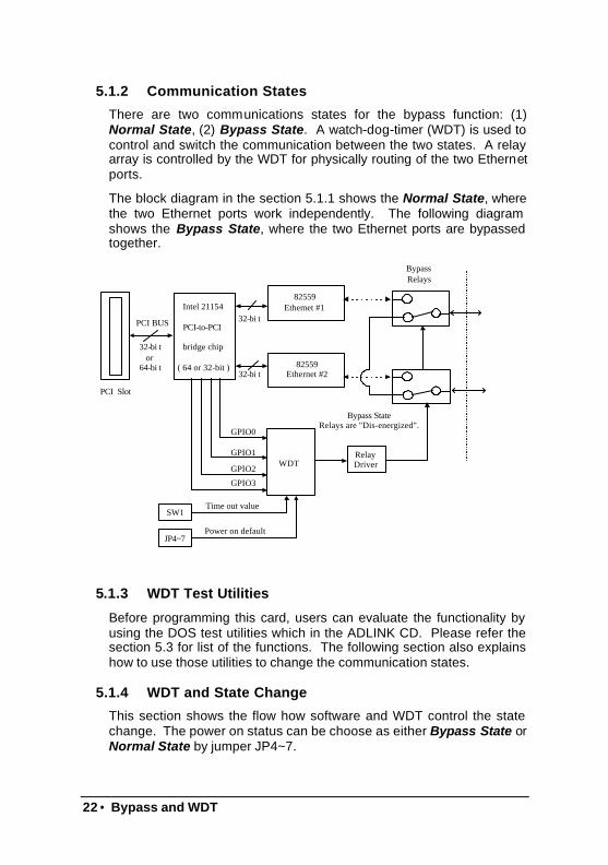
5.1.2 Communication States
There are two communications states for the bypass function: (1) Normal State, (2) Bypass State. A watch-dog-timer (WDT) is used to control and switch the communication between the two states. A relay array is controlled by the WDT for physically routing of the two Ethernet ports.
The block diagram in the section 5.1.1 shows the Normal State, where the two Ethernet ports work independently. The following diagram shows the Bypass State, where the two Ethernet ports are bypassed together.
Bypass StateRelays are "Dis-energized".
82559Ethemet #1
82559Ethernet #2
BypassRelays
WDTRelayDriver
Intel 21154
PCI-to-PCI
bridge chip
( 64 or 32-bit )
GPIO0
GPIO1
GPIO2
GPIO3
SW1
JP4~7
Time out value
Power on default
PCI BUS 32-bit
32-bit
32-bitor64-bit
PCI Slot
5.1.3 WDT Test Utilities
Before programming this card, users can evaluate the functionality by using the DOS test utilities which in the ADLINK CD. Please refer the section 5.3 for list of the functions. The following section also explains how to use those utilities to change the communication states.
5.1.4 WDT and State Change
This section shows the flow how software and WDT control the state change. The power on status can be choose as either Bypass State or Normal State by jumper JP4~7.

Bypass and WDT • 23
Default State Setting
The JP4~7 set the Default State of communication as following:
JP4
JP6
JP7
JP5
JP4
JP6
JP7
JP5
1 2 3 1 2 3
Default Normal State Default Bypass State
After the system power on or PCI reset, the communication will be in the Default State, which can be either Bypass State or Normal State. The factory default setting is the Bypass State.
When power on default setting is Bypass State
Power WDT State Note DOS Test Utility
Off Disable Bypass Relay physical character --
On Disable Bypass Default Power ON State
--
On Disable Normal Set LAN to normal mode
NOBYPASS.EXE
On Enable Normal Enable WDT and keep reload WDT
LANWDT.EXE
On Enable Bypass Enable WDT but will timeout if no reload ENWDT.EXE
On Disable Normal Disable WDT and set to normal mode
DISWDT.EXT
Off Disable Bypass Relay physical character
--

24 • Bypass and WDT
When power on default setting is Normal State Power WDT State Note Utility(DOS)
Off Disable Bypass Relay physical character
--
On Disable Normal Default Power on State
--
On Enable Normal Enable WDT and keep reload WDT
LANWDT.EXE
On Enable Bypass Enable WDT but will timeout if no reload ENWDT.EXE
On Disable Normal Disable WDT and set to normal mode
DISWDT.EXT
Off Disable Bypass Relay physical character
--
When the system is power off, the communication is in the Bypass State. After the power on, the communication will be initialed according to the JP4~7 setting. The default WDT is disabled.
The communication state will be change from Default State (either Bypass State or Normal State) into Normal State only when user enable the WDT.
Under the Normal State, the users’ software must reload the WDT to avoid timeout. Once the WDT timeout, Normal State will change to Bypass State automatically, the WDT is still enabled but keep in timeout status.
To release the timeout, user must disable the WDT by software or turn the power off. The communication will change to Default State. When the system power turns off, the communication will change to Bypass State.
Bypass and WDT • 25
5.2 WDT control
5.2.1 WDT control
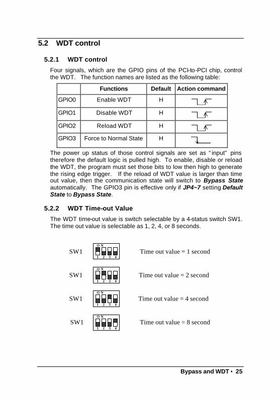
Four signals, which are the GPIO pins of the PCI-to-PCI chip, control the WDT. The function names are listed as the following table:
Functions Default Action command
GPIO0 Enable WDT H
GPIO1 Disable WDT H
GPIO2 Reload WDT H
GPIO3 Force to Normal State H
The power up status of those control signals are set as “input” pins therefore the default logic is pulled high. To enable, disable or reload the WDT, the program must set those bits to low then high to generate the rising edge trigger. If the reload of WDT value is larger than time out value, then the communication state will switch to Bypass State automatically. The GPIO3 pin is effective only if JP4~7 setting Default State to Bypass State.
5.2.2 WDT Time-out Value
The WDT time-out value is switch selectable by a 4-status switch SW1. The time out value is selectable as 1, 2, 4, or 8 seconds.
1 432
NO
SW1 Time out value = 1 second
1 432
NO
SW1
1 432
NO
SW1
1 432
NO
SW1
Time out value = 2 second
Time out value = 4 second
Time out value = 8 second

26 • Bypass and WDT
5.2.3 Programming information of the WDT
Search Intel 21154 PCI-to-PCI bridge
The first step of programming the WDT is to use the 21554 chip information (Vendor ID=1011h, Device ID=0026h, Class Code = 0604h) to search the PCI-8214 card. If the card does exist, then record the bridge’s location (Bus number, Device number and function number) for the further programming.
GPIO Programming on 21154 Chip
The GPIO0~GPIO3 pins of the 21154 chip are used to control the WDT. The following tables list the detailed bit mapping of 65h & 66h register.
GPIO Output Data Register – Offset 65h
Bit Name R/W Description
3:0 GPIO output
Write-1-to-clear R/W1TC
The gpio<3:0> pin output data write-1-to-clear. Writing 1 to any of these bits drives the corresponding bit low on the gpio<3:0> bus if it is programmed as bi-directional. Data is driven on the PCI clock cycle following completion of the configuration write to this register. Bit positions corresponding to gpio pins that are programmed as input only are not driven. Writing 0 to thes e bits has no effect. When read, reflects the last value written.
7:4 GPIO output
Write-1-to-set R/W1TS
The gpio<3:0> pin output data write-1-to-set. Writing 1 to any of these bits drives the corresponding bit high on the gpio<3:0> bus if it is programmed as bi-directional. Data is driven on the PCI clock cycle following completion of the configuration write to this register. Bit positions corresponding to gpio pins that are programmed as input only are not driven Writing 0 to these bits has no effect. When read, reflects the last value written.
GPIO Output Enable Control Register – Offset 66h Bit Name R/W Description
3:0 GPIO output
enable Write-1-to-clear
R/W1TC
The gpio<3:0> pin output data write-1-to-enable. Writing 1 to any of these bits drives the corresponding gpio<3:0> pin as input only; that is, the output driver is tristated. Writing 0 to this register has no effect. When read, reflects the last value written.

Bypass and WDT • 27
Reset value: 0 (all pins are input only)
7:4 GPIO output
enable Write-1-to-set
R/W1TS
The gpio<3:0> pin output enable control write-1-to-set. Writing 1 to any of these bits configures the corresponding gpio<3:0> pin as bi-directional, that is, enables the output driver and drives the value set in the output data register (65h). Writing 0 to these bits has no effect. When read, reflects the last value written. Reset value: 0 (all pins are input only)
Generate WDT Commands Enable WDT:
(i) Write 01h to reg#65h and 10h to reg#66h (let GPIO0 to be low) (ii) Write 10h to reg#65h (Let GPIO0 to be high)
Disable WDT: (i) Write 02h to reg#65h and 20h to reg#66h (let GPIO1 to be low) (ii) Write 20h to reg#65h (Let GPIO1 to be high)
Reload WDT: (i) Write 04h to reg#65h and 40h to reg#66h (let GPIO2 to be low) (ii) Write 40h to reg#65h (Let GPIO2 to be high)
Switch to Normal State: (i) Write 08h to reg#65h and 80h to reg#66h (let GPIO3 to be low)
Note. The GPIO3 pin is effective only if JP4~7 setting Default
State to Bypass State.

28 • Bypass and WDT
5.3 DOS Test Utility
The following four test utilities can be used for testing whether if the bypass relays work, before integrating the WDT control into user applications. You can find these 4 utilities in the directory below.
X:\NuPRO\PCI8214\WDTutility\DOS
where X is the CD-ROM drive.
ENWDT.EXE: Enable WDT. The PCI-8214 will switch to Bypass State in 1,2,4,8 seconds (or time out value) if user does not reload the WDT. When the relays switching, user should hear a click noise, which is the relay’s action.
DISWDT.EXE: Disable and stop WDT. The communication state will keep in Default State.
LANWDT.EXE: Enable WDT and keep reloading WDT. The WDT will not time-out unless the program stops running or power off. User can turn off the system power to test the bypass function.
NOBYPASS.EXE: Switch to Normal State if Default state is setting to Bypass State.
5.4 WDT DLL for Windows NT & 2000
To use the Watch Dog Timer function of PCI-8214 under Windows NT & 2000, we offer the WDT DLL in the directory below.
X:\NuPRO\PCI8214\WDTutility\NT&2K
where X is the CD-ROM drive.
There are two installation procedures to register the WDT DLL to OS. Please follow the below steps to install it.
1. Copy WDT driver to WINNT\System32\drivers. You can find the WDT driver in
X:\NuPRO\PCI8214\WDTutility\NT&2K\NTDRV \I386\Free. The file name of WDT driver is Pci8213.sys.

Bypass and WDT • 29
2. Run P8213reg.reg in X:\NuPRO\PCI8214\WDTutility\NT&2K\NTDRV to register WDT DLL to system.
3. Copy X:\NuPRO\PCI8214\WDTutility\NT&2K\Lib\LanWDT.dll to C:\WINT\System32
4. Run X:\NuPRO\PCI8214\WDTutility\NT&2K\Sample \SdkLanWDT\LanWDT.exe
5. Select index card number, enter OK. 5.5 WDT Library for Linux
5.5.1 WDT Installation for Linux
The Linux Module of WDT had been tested under Linux kernel 2.2.12 and ready for 2.4.2. They are put into X:\NuPRO\PCI8214\WDTutility\Linux directory.
To use this module for testing WDT function of PCI-8214, some steps of installation are listing as follows:
1. UNPACK Copy 8213_wdt.tgz to Linux system and decompress the 8213_wdt.tgz : tar xvzf 8213_wdt.tgz This will extract the '8213_wdt' directory with the following subdirectories: i. driver/ contains the device module and the installation script ii. drvsrc/ contains the source code for 8214 Watch Dog Timer iii. lib/ contains the shared library - libLanWDT.so iv sample/ contains the s ample programs for 8214 Watch Dog
Timer 2. INSTALL DEVICE
Execute the installation script to make nodes for PCI-8214. <InstallDir>/8213_wdt/driver/wdt_inst.pl
for driver installation To make driver installation, execute the script as follows: <InstallDir>/8213_wdt/driver/wdt_inst.pl <Number of PCI-8214 cards> ex. If you have 3 PCI-8214 cards, please install them with the following command : wdt_inst.pl 3 The optional parameter 'inst_dir ' is used to indicate the directory of PCI-8214 package. If the PCI-8214 driver can not be found in working directory, the optional parameter 'inst_dir ' is required.

30 • Bypass and WDT
ex. If you have 2 PCI-8214 cards, and install the PCI-8214 package in /usr/local/8213_wdt.
install the cards with the command : wdt_inst.pl 2 /usr/local/8213_wdt
4. INSTALL LIBRARY The library is provided as a shared library. To install the library, type the following command: Cp <InstallDir>/8213_wdt/lib/libLanWDT.so /usr/lib In addition, wdt_inst.pl also involves the installation for the library. More detailed information about Linux Module of WDT is listed in readme.dat .( X:\NuPRO\PCI8214\WDTutility\Linux)
5.5.2 WDT with C Language #include <stdio.h> #include <stdlib.h> #include <unistd.h> #include "LanWDT.h" #include "conio.h" int main( void ) { int err; int timer_interval = 200; // 200 mini-second int card_number = 0; /* for the first pci8213 */ setbuf( stdout, NULL ); if((err = LanWDT(card_number, timer_interval))<0) { //enable Watchdog timer printf("Enable WDTimer Error: %d\n", err); exit(-1); } printf(" Enable WDTimer with interval %d sec. \n", timer_interval ); printf(" \n\n Press any key to Disable WDTimer :" ); getch(); LanWDT(card_number, 0);//disable Watchdog timer putchar('\n'); return 0; }

Warranty Policy • 31
Warranty Policy
Thank you for choosing ADLINK. To understand your rights and enjoy all the after-sales services we offer, please read the following carefully.
1. Before using ADLINK’s products, please read the user manual and follow the instructions exactly. When sending in damaged products for repair, please attach an RMA application form.
2. All ADLINK products come with a two-year guarantee,free of repair charge.
• The warranty period starts from the product’s shipment date from ADLINK’s factory
• Peripherals and third-party products not manufactured by ADLINK will be covered by the original manufacturers’ warranty
• End users requiring maintenance services should contact their local dealers. Local warranty conditions will depend on the local dealers 3. Our repair service does not cover two-year guarantee while damages are caused by the following:
a. Damage caused by not following instructions on user menus.
b. Damage caused by carelessness on the users’ part during product transportation.
c. Damage caused by fire, earthquakes, floods, lightening, pollution and incorrect usage of voltage transformers.
d. Damage caused by unsuitable storage environments with high temperatures, high humidity or volatile chemicals.
e. Damage caused by leakage of battery fluid when changing batteries.
f. Damages from improper repair by unauthorized technicians.
g. Products with altered and damaged serial numbers are not entitled to our service.
h. Other categories not protected under our guarantees.4. Customers are responsible for the fees regarding transportation of damaged products to our company or to the sales office.

32 • Warranty Policy
5. To ensure the speed and quality of product repair, please download an RMA application form from our company website www.adlinktech.com. Damaged products with RMA forms attached receive priority.
For further questions, please contact our FAE staff.
ADLINK: [email protected]
Test & Measurement Product Segment: [email protected]
Automation Product Segment: [email protected]
Computer & Communication Product Segment: [email protected] ; [email protected]


