PCI MANUAL FOR THE DESIGN OF HOLLOW CORE SLABS SECOND EDITION by Donald R. Buettner and Roger J. Becker Computerized Structural Design, S.C. Prepared for the PCI Hollow Core Slab Producers Committee John E. Saccoman, Chairperson James Beerbower Ernest Markle Kevin Boyle James Markle Jeffrey Butler Milo J. Nimmer Loris Collavino William C. Richardson, Jr. Edward J. Gregory Klaus Rosenstern Pat Hynes Wes Schrooten Paul Kourajian Larry Stigler PRECAST / PRESTRESSED CONCRETE INSTITUTE 175 WEST JACKSON BOULEVARD CHICAGO, ILLINOIS 60604 312 786--0300 FAX 312 786--0353
Transcript
PCIMANUAL FOR THE DESIGN
OFHOLLOW CORE SLABS
SECOND EDITION
by
Donald R. Buettner and Roger J. BeckerComputerized Structural Design, S.C.
Prepared for thePCI Hollow Core Slab Producers
Committee
John E. Saccoman, Chairperson
James Beerbower Ernest MarkleKevin Boyle James MarkleJeffrey Butler Milo J. NimmerLoris Collavino William C. Richardson, Jr.Edward J. Gregory Klaus RosensternPat Hynes Wes SchrootenPaul Kourajian Larry Stigler
PRECAST / PRESTRESSED CONCRETE INSTITUTE175 WEST JACKSON BOULEVARDCHICAGO, ILLINOIS 60604
312 786--0300 FAX 312 786--0353
Copyright 1998
By Precast/Prestressed Concrete Institute
First edition, 1985
Second edition, 1998
All rights reserved. This book or any part thereof may not be
reproduced in any form without the written permission of the
Precast/Prestressed Concrete Institute.
ISBN 0--937040--57--6
Printed in U.S.A.
INTRODUCTION
Purpose of Manual
The application and design of precast, prestressed hollow core slabs is similar to that of other pre-stressed members. However, there are situations which are unique to hollow core slabs either be-cause of the way the slabs are produced or because of the application of the slabs.
For special situations, hollow core producers have developed design criteria and conducted in-house testing to verify that their approaches are valid. In fact, there is consistency between the manytypes of hollow core slabs available. The purpose of this manual is to bring together those things thatare common, that are verified by test and that can be universally applied to hollow core slabs. Be-cause there are differences, some topics covered will also point to the differences where closer coor-dination with the local producer is required.
This manual was prepared by Computerized Structural Design, S.C., Milwaukee, Wisconsin withinput and direction from the PCI Hollow Core Slab Producers Committee. Additionally, the fire andacoustical sections were prepared by Armand Gustaferro of The Consulting Engineers Group, Inc.,Mt. Prospect, Illinois and Allen H. Shiner of Shiner and Associates, Inc., Skokie, Illinois, respective-ly. All reasonable care has been used to verify the accuracy of material contained in this manual.However, the manual should be used only by those experienced in structural design and should notreplace good structural engineering judgment.
Scope of Manual
This document is intended to cover the primary design requirements for hollow core floor androof systems. In instances where the design is no different than for other prestressed members, thePCI Design Handbook and the ACIBuilding Code should be consulted formore in-depth discussion.
For the architect or consulting engineer, this manual is intended as a guideline for working withhollow core slabs, a guide for the use and application of hollow core slabs and an indication of someof the limitations of hollow core slabs. For the plant engineer, the manual will hopefully presentsome backup and reference material for dealing with everyday design problems.
A = Cross-sectional areaa = Depth of equivalent compression stress
blockaθ = Depth of equivalent compression stress
block under fire conditionsAcr = Area of crack faceAe = Net effective slab bearing areaAps = Area of prestressed reinforcementAvf = Area of shear friction reinforcementb = Width of compression facebw = Net web width of hollow core slabC = Confinement factorC = Compressive forceC = Seismic factor dependent on site and
structure fundamental periodC = Factor for calculating steel relaxation
losses as given in Table 2.2.3.2c = Distance from extreme compression
fiber to neutral axisCR = Prestress loss due to concrete creepCs = Seismic coefficientD = Dead loadd = Distance from extreme compression fiber
to centroid of non-prestressedtension reinforcement
db = Nominal diameter of reinforcementdp = Distance from extreme compression fiber
to centroid of prestressedreinforcement
DW = Distribution widthe = Distance from neutral axis to centroid of
prestressed reinforcementEc = Modulus of elasticity of concreteEci = Modulus of elasticity of concrete at the
time of initial prestressES = Prestress loss due to elastic shortening of
concreteEs = Modulus of elasticity of steel
reinforcementf′c = Specified design compressive strength of
concretef′ci = Compressive strength of concrete at the
time of initial prestressfcir = Net compressive stress in concrete at
centroid of prestressed reinforcement attime of initial prestress
fcds = Stress in concrete at centroid ofprestressed reinforcement due tosuperimposed dead load
fd = Stress at extreme tension fiber due tounfactored member self weight
Fi = Portion of base shear applied at level ifpc = Compressive stress in concrete at the
centroid of the section due to effectiveprestress for non-composite sections ordue to effective prestress and momentsresisted by the precast section alone forcomposite sections
fpe = Compressive stress in concrete at extremefiber where external loads cause tensiondue to the effective prestress only
fps = Stress in prestressed reinforcement atnominal strength
fpsθ = Stress in prestressed reinforcement at firestrength
f′ps = Maximum steel stress in partiallydeveloped strand
L = Live loadℓ = Span lengthℓd = Reinforcement development lengthℓe = Strand embedment length from member
end to point of maximum stressℓf = Flexural bond lengthℓt = Strand transfer lengthM = Service load momentMcr = Cracking momentMd = Unfactored dead load momentMg = Unfactored self-weight momentMn = Nominal flexural strengthMnθ = Flexural strength under fire conditionsMmax = Maximum factored moment due to
externally applied loads= Mu -- Md
Msd = Unfactored moment due tosuperimposed dead load
Mu = Factored design momentMθ = Applied fire momentP = Effective force in prestressing steel after
all lossesPo = Effective prestress force at release prior to
long term lossesPi = Initial prestress force after seating lossesQ = First moment of areaR = Fire endurance ratingRE = Prestress loss due to steel relaxationRe = Reduction factor for load eccentricity in
structural system typeS = Section modulusSH = Prestress loss due to concrete shrinkageT = Tensile forcetg = Width of grout column in horizontal jointV = Seismic base shearVc = Nominal shear strength of concreteVci = Nominal shear strength of concrete in a
shear-flexure failure modeVcw = Nominal shear strength of concrete in a
web shear failure modeVd = Shear due to unfactored self weightVh = Horizontal beam shear
Vi = Factored shear force due to externallyapplied loads occurring simultaneouslywith Mmax
= Vu -- VdVn = Nominal shear strength of a memberVs = Nominal shear strength provided by shear
reinforcementVu = Design shear forceV/S = Volume to surface ratiow = Uniformly distributed loadw = Bearing area lengthW = Total dead load plus other applicable
loads for seismic designwi = Portion of W at level iwpx = Portion of W at level under
considerationyb = Distance from neutral axis to extreme
bottom fiberyt = Used as either distance to top fiber or
tension fiber from neutral axisZ = Seismic zone factorβ1 = Factor defined in ACI 318-95, Section
10.2.7.3γp = Factor for type of prestressing strandδall = Limiting free end slipδs = Actual free end slipεps = Strain in prestressed reinforcement at
nominal flexural strengthεs = Strain in prestressed reinforcementεse = Strain in prestressed reinforcement after
lossesµ = Shear friction coefficientµe = Effective shear friction coefficientρp = Ratio of prestressed reinforcementρ′ = Ratio of compression reinforcementφ = ACI strength reduction factorω = ρfy/f′cω′ = ρ′fy/f′cωp = ρpfps/f′cωw = Reinforcement index for flanged sectionsω′w = Reinforcement index for flanged sectionsωpw = Reinforcement index for flanged sectionsωpu = ρp fpu/f′cθ = Subscript denoting fire conditions
CHAPTER 1
1--1
HOLLOW CORE SLAB SYSTEMS
1.1 Methods of ManufacturingA hollow core slab is a precast, prestressed con-
crete member with continuous voids provided toreduce weight and, therefore, cost and, as a sidebenefit, to use for concealed electrical or mechan-ical runs. Primarily used as floor or roof deck sys-tems, hollow core slabs also have applications aswall panels, spandrel members and bridge deckunits.
An understanding of the methods used tomanufacture hollow core slabs will aid in the spe-cial considerations sometimes required in the useof hollow core slabs. Hollow core slabs are castusing various methods in the seven major systemsavailable today. Because each production systemis patented, producers are usually set up on a fran-chise or license basis using the background,knowledge and expertise provided with the ma-chine development. Each producer then has thetechnical support of a large network of associatedproducers.
Two basic manufacturing methods are current-ly in use for the production of hollow core slabs.One is a dry cast or extrusion system where a verylow slump concrete is forced through the ma-chine. The cores are formed with augers or tubeswith the concrete being compacted around thecores. The second system uses a higher slumpconcrete. Sides are formed either with stationary,fixed forms or with forms attached to the machinewith the sides being slip formed. The cores in thenormal slump, or wet cast, systems are formedwith either lightweight aggregate fed throughtubes attached to the casting machine, pneumatictubes anchored in a fixed form or long tubes at-tached to the casting machine which slip form thecores.
Table 1.1 lists the seven major hollow core sys-tems available today along with the basic in-formation on the casting technique. Variousnames may be used by local licensees to describethe same products. In most cases, the slabs arecast on long line beds, normally 300 ft to 600 ft
long. Slabs are then sawcut to the appropriatelength for the intended project.
The economy of the generalized hollow coresystem is in the quantity of slabs that can be pro-duced at a given time with a minimum of labor re-quired. Each slab on a given casting line will havethe same number of prestressing strands. There-fore, the greatest production efficiency is obtainedby mixing slabs with the same reinforcing re-quirements from several projects on a single pro-duction line. This implies that best efficiency for asingle project is obtained if slab requirements arerepetitive.1.2 Materials
As stated previously, hollow core slabs are pro-duced with two basic concrete mixes; low slumpand normal slump concrete. For the low slumpconcretes, water content is limited to slightlymore than that required for cement hydration.Water-cement ratios are typically about 0.3. Mix-ing is critical because the limited water availablemust be well dispersed in the mix. Water reducingadmixtures can be used to optimize a mix by re-ducing cement and water requirements while stillretaining adequate workability for proper com-paction of the concrete by the machine. Air en-trainment admixtures are not effective in the drymix concrete. With the low water-cement ratiosand compaction placing method, air is difficult todisperse well and maintain.
Table 1.1 Hollow Core Systems
Manufac-turer
MachineType
ConcreteType/Slump
Core Form
Dy-Core Extruder Dry/Low Tubes
Dynaspan Slip Form Wet/Normal Tubes
Elematic Extruder Dry/Low Auger/Tube
Flexicore Fixed Form Wet/Normal PneumaticTubes
Spancrete Slip Form Dry/Low Tubes
SpanDeck Slip Form Wet/Normal Filleraggregate
Ultra-Span Extruder Dry/Low Augers
1--2
Latex feathering ready for direct carpet application
Acoustical spray on exposed slab ceiling
Electrical and HVAC application
The wet cast products (those cast with normalslump concrete), have water-cement ratios in therange of 0.4 to 0.45. Depending on the slip form-ing system used, slumps of 2 to 5 inches (50 - 130mm) are used. The mix design and use of admix-tures is dependent on achieving a mix that willhold its shape consistent with the forming tech-nique used.
Aggregates vary in the various manufacturingprocesses depending on what type is locally avail-able. Maximum aggregate size larger than peagravel is rarely used because of the confined areasinto which concrete must be placed. Light weightaggregates are occasionally used to reduce theweight of the sections and to achieve a significantreduction in required equivalent thickness in a firerated application. Concrete unit weights rangingfrom 110 to 150 pcf (1760 - 2400 kg/m3) are usedin the industry.
Strand use in hollow core slabs includes aboutevery size and type of strand produced dependingon what is available to a particular producer. Thetrend is toward primary use of the larger 1/2 in (13mm) diameter, low relaxation strand. The philos-ophy of strand use varies from using many strandsizes to optimize cost for a given project to usingonly one or two strand sizes for simplicity of in-ventory and production.
Except for special situations, keyway grout isnormally a sand and Portland cement mixture inproportions of about 3:1. The amount of waterused is a function of the method used to place thegrout but will generally result in a wet mix so key-ways may be easily filled. Shrinkage cracks mayoccur in the keyways, but configuration of the keyis such that vertical load transfer can still occurwith the presence of a shrinkage crack. Rarely isgrout strength required in excess of 2000 psi (13.8MPa) for vertical load transfer.
Although it is discouraged, non-shrink, non-staining grout is occasionally specified for use inkeyways. In evaluating the potential benefits ofnon-shrink grout, the volume of grout must becompared to the overall volume of concrete in theslabs and support materials. Because the size ofthe keyway is small in relation to a floor or roof as-sembly of slabs, total shrinkage will be affectedonly to a minor degree. Shrinkage cracks can still
1--3
occur in the keyways and there is little benefit tobe gained in comparison with the additional cost.
1.3 Advantages of Hollow Core SlabsHollow core slabs are most widely known for
providing economical, efficient floor and roofsystems. The top surface can be prepared for theinstallation of a floor covering by feathering thejoints with a latex cement, installing non-structur-al fill concretes ranging from 1/2 in to 2 in (13 - 51mm) thick depending on the material used, or bycasting a composite structural concrete topping.The underside can be used as a finished ceiling asinstalled, by painting, or by applying an acousticalspray.
When properly coordinated for alignment, thevoids in a hollow core slab may be used for electri-cal or mechanical runs. For example, routing of alighting circuit through the cores can allow fix-tures in an exposed slab ceiling without unsightlysurface mounted conduit. Slabs used as the heatedmass in a passive solar application can be detailedto distribute the heated air through the cores.
Structurally, a hollow core slab provides the ef-ficiency of a prestressed member for load capac-ity, span range, and deflection control. In addi-tion, a basic diaphragm is provided for resistinglateral loads by the grouted slab assembly pro-vided proper connections and details exist. A de-tailed discussion of diaphragm capabilities ispresented in Chapter 4.
Excellent fire resistance is another attribute ofthe hollow core slab. Depending on thickness andstrand cover, ratings up to a 4 hour endurance canbe achieved. A fire rating is dependent on equiva-lent thickness for heat transmission, concrete cov-er over the prestressing strands for strength in ahigh temperature condition, and end restraint.Underwriters Laboratories publishes fire ratingsfor various assemblies. However, many buildingcodes allow a rational design procedure forstrength in a fire. This procedure, described in de-tail in Chapter 6, considers strand temperature incalculating strength. Required fire ratings shouldbe clearly specified in the contract documents.Also, the fire rating should be considered in deter-mining the slab thickness to be used in prelimi-nary design.
Used as floor-ceiling assemblies, hollow coreslabs have the excellent sound transmission char-
acteristics associated with concrete. The SoundTransmission Class rating ranges from about 47 to57 without topping and the Impact InsulationClass rating starts at about 23 for a plain slab andmay be increased to over 70 with the addition ofcarpeting and padding. Detailed information onthe acoustical properties of hollow core slabs ispresented in Chapter 7.
1.4 Framing ConceptsThe primary consideration in developing a
framing scheme using hollow core slabs is thespan length. For a given loading and fire endur-ance rating, span length and slab thickness may beoptimized by consulting a producer’s publishedload tables. Section 1.7 presents sample loadtables and instructions for the use of the tables.The PCI Design Handbook1 recommends limitson span-depth ratios for the hollow core slabs. Forroof slabs, a span-depth ratio limit of 50 is sug-gested and for floor slabs, a limit of 40 is sug-gested. In practice, a span-depth ratio of 45 iscommon for floors and roofs when fire endurance,openings, or heavy or sustained live loads do notcontrol a design.
Consideration must be given to factors whichaffect slab thickness selection for a given span.Heavy superimposed loads, as required by thefunction of a system, would require a lower span-depth ratio. Similarly, heavy partitions or a largenumber of openings will result in higher load ca-pacity requirements. The fire resistance rating re-quired for the application will also affect the loadcapacity of a slab. As the code required fire ratingincreases, prestressing strands can be raised formore protection from the heat. The smaller effec-tive strand depth will result in a lower load capac-ity. Alternatively, a rational design procedure canbe used to consider the elevated strand tempera-tures during a fire. This fire design condition maycontrol a slab design and, again, result in a lowerload capacity.
Once slab thicknesses and spans are selected,the economics of layout become important.While ends cut at an angle can be designed andsupplied, it is most efficient to have the bearingperpendicular to the span so square cut ends canbe used.
It is also desirable to have the plan dimensionsfit the slab module. This is dependent upon the
1--4
slab systems available in the project area.Non-module plan dimensions can be accommo-dated using partial width slabs. Some producersintentionally cast narrow widths as filler pieceswhile others use a section split from a full slab.Such a split section might be created by a longitu-dinal sawcut or a break if the edge will not be ex-posed to view.
Construction tolerances must be accounted forin developing a plan layout. Tolerance on slablength may be taken up by allowing a gap at theslab ends in the bearing detail. On thenon-bearingsides, clearance may be provided by using a detailwhere the slabs lap over a wall or beam. If the slabedge butts a wall or beam, a gap should be pro-vided. Refer to local producers’ information forrecommendations of proper tolerances.
When a hollow core slab deck is exposed toweather for a long period of time during construc-tion, water can accumulate in the cores. The pri-mary source of water infiltration is at the buttjoints. In cold weather, this water can freeze andexpand causing localized damage. One remedyfor this situation is to drill weep holes at the slabends under each core. The need for such weepholes is generally known only after a constructionschedule is established. The specifier and the slabsupplier are not usually in a position to know ofsuch a need in advance.
Hollow core members will be cambered as withany other prestressed flexural member. In theplanning stages, consideration should be given tothe causes of differential camber. For two slabs ofidentical length and prestressing, the camber maybe different because of concrete and curing varia-tions. This factor is independent of a framingscheme. However, joints between slabs of un-equal spans or joints at which a change in the spandirection occurs, will cause a potential differentialcamber problem. This must be recognized anddealt with in the design layout. Wall locationsmay hide such a joint, but the door swing might bedirected to the least variable side.
Camber must also be accommodated when atopping is to be provided. The quantity of toppingrequired must consider the amount of camber andthe function of the floor. In occupancies whereflat floors are not a requirement, a constant top-ping thickness may be used to follow the curva-
ture of the slabs. At the other extreme, if a “flat”floor is required in a structure consisting of multi-ple bays of varying length and change in slabdirection, the highest point will determine the topelevation of the topping. A greater amount of top-ping will then be required in “low” areas. Theseconsiderations must be dealt with in the planningstages to both control costs and minimize ques-tions and potential for “extras” during construc-tion.
Camber, camber growth, and deflections mustbe considered when slabs run parallel to a stiff ver-tical element such as a wall (e.g. slabs runningparallel to the front wall of an elevator). The doorrough opening should allow for camber to pro-duce proper door installation. Alternatively, theslab span might be rearranged so the front wall is abearing wall. Then door problems would be alle-viated.
Camber, camber growth, and deflections mustbe taken into account in roofing details. Wherechanges in relative slab position can occur, coun-terflashings are suggested to accommodate suchchanges.
1.5 Wall Panel ApplicationsSome hollow core slab systems can also pro-
vide slabs to be used as walls. Long line manufac-turing can result in economical cladding or loadbearing panels used in manufacturing or commer-cial applications. The hollow core wall panels areprestressed with two layers of strands for accom-modating handling, structural loadings and bow-ing considerations. Some manufacturers can add2 in to 4 in (51 - 102 mm) of insulation to the hol-low core section with a 1 1/2 in thick to 3 in (38 - 76mm) thick concrete facing to create an insulatedsandwich panel.
A variety of architectural finishes are availablewith hollow core wall panels. While the finishescan be very good, the variety of finishes availableis different from those typically available withtrue architectural precast concrete panels. Injudging the quality of finish on hollow core wallpanels, consideration must be given to themanufacturing process.
1--5
1.6 Design ResponsibilitiesIt is customary in the hollow core industry for
the producer to perform the final engineering forthe product to be supplied to the job. This wouldinclude design for vertical loads and lateral loadsspecified by the Engineer of Record, embeddeditems for specified connection forces, and han-dling and shipping. However, the Engineer of Re-cord plays a very important role in the design pro-cess. Prior to selection of the hollow core produc-er, enough preliminary planning should be done toinsure that the specified floor and roof system isachievable. That is, the project should be one thatcan be engineered without requiring changes fromthe contract documents.
The contract documents must clearly indicatedesign criteria to which hollow core slabs willhave to conform. This is especially importantwhen the hollow core slabs must interface withother construction materials. When connectionsare required, the forces to be transmitted throughthe connections must be specified in the contractdocuments. The producer is best able to deter-mine the most efficient connection element to beembedded in the slab. However, the balance of aconnection which interfaces with another materi-al should be detailed in the contract documents.
The Engineer of Record also has a responsibil-ity in the review and approval of erection draw-ings prepared by the precast producer. Review ofthese drawings is the last opportunity to assurethat the producer’s understanding of the projectcoincides with the intent of design. Erectiondrawings should be checked for proper designloads, proper details and bearing conditions, con-formance with specified fire ratings, and the loca-tion of openings.
1.7 Cross-Sections and Load TablesEach of the major hollow core slab systems has
a standard set of cross-sections that can be pro-duced by their equipment. Available in thick-nesses ranging from 4 in to 15 in (102 - 380 mm),core configurations make each system unique.Each individual producer has additional produc-tion practices which may affect the capabilities oftheir product. Therefore, most producers prepareand distribute load tables in their market area.
Producer load tables define the allowable liveload that a given slab can safely support in addi-tion to the slab self weight. The load capacity willbe a function of the slab thickness, the amount ofprestressing provided, and the location of the pre-stressing strands. Fire rated slabs may requireadditional concrete cover below the strands whichwill affect the load capacity.
The design criteria used to develop these loadtables is defined by the ACI Building Code2 asoutlined in Chapter 2. Depending on the designcriteria controlling a slab’s load capacity, someadvantage may be gained by understanding that inmost applications, superimposed loads will con-sist of both dead and live loads. Where ultimatestrength controls, an equivalent live load can beused to enter a load table. It is calculated as:
wequivalent =1.41.7
superimposed Dead load
+ Live loadHowever, if bottom fiber tensile stresses con-
trol, no adjustment in superimposed loads may beused.
Similarly, many loading conditions consist ofloads other than uniform loads. For preliminarydesign only, an equivalent uniform load may becalculated from the maximum moment caused bythe actual loads.
wequivalent =8 Msuperimposed
ℓ2
Shear will not be properly addressed in this sit-uation. Thus, the final design must consider theactual load pattern.
Because of the uniqueness of each hollow coreslab system and the many possibilities of strandpatterns available from various producers, a ge-neric hollow core slab has been developed to dem-onstrate design procedures. Figure 1.7.1 depictsthe slab section and properties and illustrates atypical form for a producer’s load tables.Throughout this manual, this section will be usedto demonstrate various calculation procedureswhere any one of the proprietary cross-sectionscould be substituted. It must be emphasized thatthis cross-section is not available for use andshould not be specified.
Figures 1.7.2 through 1.7.8 present the propri-etary slab cross-sections currently available. Thesection properties are as provided by the manufac-
1--6
turers, but weights are based on 150 pcf (2400kg/m3) concrete. The actual weights may varyslightly from those given. The availability of anyparticular section in a given area must be verifiedwith the local producers. Figures 1.7.9 presentcharts of the general range of load capacitiesavailable in a given slab thickness. As with anychart of this nature, the chart should be carefullyapproached and verified with local producer loadtables, especially for the longest and shortest andlightest and heaviest conditions. Special care isalso required when fire rated slabs must be usedon a project. (See Chapter 6)
The following examples demonstrate the waysin which load tables may be used.
Example 1.7.1 Equivalent Uniform LoadFrom the load table in Figure 1.7.1 select a
strand pattern to carry a uniform superimposeddead load of 20 psf and a uniform live load of 60psf on a 24 foot span.
Use 4-3/8 in dia. strands: capacity = 79 psfflexural strength controls.
Example 1.7.2 Non-Uniform LoadsFrom the load table in Figure 1.7.1 select a
strand pattern to carry a superimposed uniformload of 20 psf dead plus 40 psf live and a continu-ous wall load of 600 plf located perpendicular tothe span and at midspan. The design span is 25feet.For preliminary design
Msuperimposed =252
820+ 40+ 25
4600
= 8438
wequivalent =88438
252
= 108 psf
ft-#/ft
Try 6-3/8 in dia. strands - capacity = 120 psf
For final design use the methods of Chapter 2particularly to check shear.
1.8 Tolerances3
Figure 1.8.1 shows the dimensional tolerancesfor precast hollow core slabs. These tolerancesare guidelines only and each project must be con-sidered individually to ensure that the tolerancesshown are applicable.
Figure 1.8.2 shows erection tolerances for hol-low core slabs. When establishing tolerances, thefunction of the slabs should be considered. Forexample, slabs covered by finish materials maynot need the close tolerances required for exposedslabs.
1 - Values are governed by shear strength.2 - Values are governed by allowable tension3 - Table based on 5000 psi concrete with allowable tension. Unless noted, values are
governed by strength design.
Note: This slab is for illustration purposes only. Do not specify this slab for a project.
6 f′c
Fig. 1.7.1 Generic hollow core slab
8"
5 1/
4"1
1/4"
1 1/
2"
4 1/4"1 1/2"1 1/2" 1"
36"
1--8
Fig. 1.7.2
Note: All sections not available from all producers. Check availability with local manufacturers.
Top flange area defined by the actual measured values ofaverage dt x b shall not be less than 85% of the nominal areacalculated by dt nominal x b nominal.
db = Bottom flange thicknessBottom flange area defined by the actual measured valuesof average db x b shall not be less than 85% of the nominalarea calculated by db nominal x b nominal.
e = Web thicknessThe total cumulative web thickness defined by the actualmeasured valueΣe shall not be less than 85% of the nominalcumulative width calculated by Σe nominal.
f = Blockout location ±2 in. . . . . . . . . . . . . . . . . . . . . . . . . . . . . .g = Flange angle 1/8 in per 12 in, 1/2 in max.. . . . . . . . . . . . . .h = Variation from specified end squareness
or skew ±1/2 in. . . . . . . . . . . . . . . . . . . . . . . . . . . . . . . . . . . .i = Sweep (variation from straight line parallel to centerline of
j = Center of gravity of strand groupThe CG of the strand group relative to the top of the plankshall be within ±1/4 in of the nominal strand group CG. Theposition of any individual strand shall be within ±1/2 in ofnominal vertical position and ±3/4 in of nominal horizontalposition and shall have a minimum cover of 3/4 in.
k = Position of plates ±2 in. . . . . . . . . . . . . . . . . . . . . . . . . . . . . .l = Tipping and flushness of plates ±1/4 in. . . . . . . . . . . . . . . .m = Local smoothness ±1/4 in in 10 ft. . . . . . . . . . . . . . . . . . . . .
(does not apply to top deck surface left rough to receive atopping or to visually concealed surfaces)
Plank weightExcess concrete material in the plank internal features iswithin tolerance as long as the measured weight of theindividual plank does not exceed 110% of the nominalpublished unit weight used in the load capacity calculation.
n = Applications requiring close control of differential camberbetween adjacent members of the same design should bediscussed in detail with the producer to determine applicabletolerances.
b
c
d b
td
e
CROSS SECTION
CGS
j
k
k
g
m
10 ft
fi
l
n
h
PLAN
ELEVATION
a
1--15
Fig. 1.8.2 Erection tolerances - hollow core floor and roof members
* For precast concrete erected on a steel frame building, this tolerance takes precedence over tolerance on dimension “a”.** It may be necessary to feather the edges to ± 1/4 in to properly apply some roof membranes.
*** This is a setting tolerance and should not be confused with structural performance requirements set by the architect/engineer.**** Untopped installation will require a larger tolerance here.
e
gf
bldg. elevation datum
b
clearance
d
c
a
a bldg. Y grid datum
bldg. X grid datum
hollow corefloor or roof member
f
a1
ELEVATION
bldg. elevation datum
b
ELEVATION
Precast element to precast orcast-in-place concrete or masonry
floor or roof memberhollow core
precast or cast in placeconcrete support member
centerline of floor or roof memberhollow core
bldg. X grid datum
bldg. Y grid datum
d
c
a
f
a
Precast element to structural steel
g
e
PLAN PLANsteel structure
centerline ofsteel structure
CHAPTER 2
2--1
DESIGN OF HOLLOW CORE SLABS
2.1 GeneralThe design of hollow core slabs is governed by
the ACI (318-95) Building Code Requirementsfor Structural Concrete.2 As with prestressed con-crete members in general, hollow core slabs arechecked for prestress transfer stresses, handlingstresses, service load stresses, deflections and de-sign (ultimate) strength in shear and bending. Foruniform load cases, the manufacturer’s load tableswill take into account these various design consid-erations and print a load capacity based on thegoverning criteria. For loading conditions otherthan uniform, or for the development of loadtables, the design steps presented in this sectionare used.
An excellent reference for prestressed memberdesign exists in the PCI Design Handbook.1Charts and tables provide design aids to shortenthe calculation procedures. Another excellentsource for design information is the PCI StandardDesign Practice4 which reflects design practicesin the industry.
The generic slab presented in Section 1.7 willbe used for the calculations presented in this sec-tion. The cross-section was selected to provide ameans of demonstrating calculation proceduresand does not represent any slab currently in use.Therefore, this generic slab should never be speci-fied for use on a project. See Section 1.7 for theslabs currently available.
2.2 Flexural Design
2.2.1 ACI RequirementsChapter 18 of ACI (318-95) presents provi-
sions for the flexural design of prestressed con-crete members. The applicable limits from ACIare paraphrased as follows:
2.2.1.1 Permissible stresses at transfer(Section 18.4).a) Extreme fiber stress in compression
2.2.1.3 Loss of prestress (Section 18.6)Calculation of losses shall consider:a) Seating lossb) Elastic shortening of concretec) Creep of concreted) Shrinkage of concretee) Steel relaxation
U = 1.4D + 1.7Lb) Strength Reduction Factors (Section
9.3)Flexure φ = 0.9
c) Flexural Strength (Section 18.7)
Mu ≤ φMn = ÔApsfpsdp − a2
a =Apsfps
0.85f′cbfps = value calculated by strain
compatibility
2--2
or
fps = fpu1− γp
β1pfpu
f′cρ
Mn > 1.2 Mcr
2.2.2 Stresses at TransferWhen the prestressing strands are cut to apply
the prestressing force to the concrete, only the slabself weight is present to counteract the effects ofeccentric prestress. A check of stresses is requiredat this point to determine the concrete strength re-quired to preclude cracking on the tension side orcrushing on the compression side. The concretestrength at the time of transfer may be only 50% to60% of the 28 day design strength.
Example 2.2.2.1 - Transfer StressesUsing the generic hollow core cross-section
defined in Section 1.7, check stresses at transfer ofprestress using the following criteria:
Solution:Stresses will be checked at the transfer point
and at midspanAt release prestress force
Po = (0.70)(0.95)(0.612)(270) = 109.9kPrestress effect
= PoA
PoeS
= 109.9154
109.92.89
297.9314.8
= --0.353 ksi top fiber
= +1.723 ksi bottom fiber
Self weight at transfer point
ℓt = 50db = 50(1/2) = 25 in
moment 25 in from slab end
Md = 30.52
2.08− 2.082
20.05353′
= 4.74 ft-k
MdS
=4.7412
279.9314.8
= +0.191 ksi top fiber= --0.181 ksi bottom fiber
Net concrete stress at transfer point= --0.162 ksi top fiber= +1.542 ksi bottom fiber
Self weight at midspan
Md = 30.52
8(0.0535)(3′) = 18.66 ft-k
MdS
=18.6612
279.9314.8
= +0.752 ksi top fiber= --0.711 ksi bottom fiber
Net concrete stress at midspan= +0.399 ksi top fiber= +1.012 ksi bottom fiber
Allowable stresses:
tension at end = 6 f′ci
f′ci = − 16262
= 729 psi
tension at midspan = 3 f′cidoes not control
compression = 0.6 f′ci
f′ci = 15420.6
= 2570 psi
Concrete strength required at release= 2570 psi
Note that if tension or compression in the endregion exceeds allowables based on a reasonableconcrete release strength, strands may be de-bonded in some manufacturing systems or, fortension, top mild reinforcement may be used insome manufacturing systems to resist the totaltension force.
2--3
If tension in the midspan region controls, eithera high release strength must be used or mild rein-forcement must be added to resist the total tensionforce. Mild reinforcement should only be used inthe wet cast manufacturing system.
2.2.3 Prestress LossesThe calculation of prestress losses affects the
service load behavior of a slab. The accuracy ofany calculation method is dependent on the pre-ciseness of concrete and prestressing steel materi-al properties as well as external factors such as hu-midity used in the calculation procedure. Theaccuracy of loss calculations has little effect onthe ultimate strength of a member.
Prestress loss calculations are required for pre-diction of camber and for service load stress cal-culations. Since the success of a project is judgedon service load performance rather than ultimatestrength, it behooves any slab producer to use aloss calculation procedure which best predicts thebehavior of the product as produced.
For low relaxation strand and for special cases(e.g., long spans or special loadings) using stressrelieved strand, the 1995 ACI Code referencesseveral sources for prestress loss calculations.The method presented here was developed by Zia,et al.5 and considers the following parameters:
1) Elastic Shortening
ES = KesEsEci
fcir
Kes = 1.0 for pretensioned members
fcir = Kcir PiA+ Pie2
I −MgeI
Kcir = 0.9 for pretensioned members
2) Concrete Creep
CR = KcrEsEc
(fcir -- fcds)
Kcr = 2.0 for normal weight pretensionedmembers
= 1.6 for sand lightweight pretensionedmembers
fcds =Msde
I3) Shrinkage of Concrete
SH = 8.2 x 10⁻⁶KshEs1− 0.06 VS
x (100 -- RH)
Fig. 2.2.3.1 Ambient relative humidity
8070
70
60
80
7060 40
30
40 50
4050 60
7075
7075
70
80
70
7570
2--4
Table 2.2.3.1Type of tendon Kre psi J
270 Grade stress-re-lieved strand or wire 20,000 0.15
250 Grade stress-re-lieved strand or wire 18,500 0.14
240 or 235 Grade stress-relieved wire 17,600 0.13
270 Grade low-relax-ation strand 5000 0.040
250 Grade low-relax-ation wire 4630 0.037
240 or 235 Grade low-re-laxation wire 4400 0.035
145 or 160 Grade stress-relieved bar 6000 0.05
Ksh = 1.0 for pretensioned members
RH = Ambient relative humidity from Fig-ure 2.2.3.1
4) Steel Relaxation
RE = [Kre -- J (SH + CR + ES)]C
Kre, J, C = factors from Tables 2.2.3.1and 2.2.3.2
5) Total Loss = ES + CR + SH + RE
Observations and experience in a plant mayprovide modifications to loss calculations to bet-ter predict slab performance.
Example 2.2.3.1 Loss of PrestressUsing the generic hollow core cross-section
defined in Section 1.7, calculate the loss of pre-stress based on the following information:
2.2.4 Service Load StressesService load concrete stresses are calculated as
a measure of performance or serviceability. Forthe in-service state when deflections must be cal-culated, a stress check must first be made to deter-mine whether gross section properties or cracked-transformed section properties are to be used.
In-service stresses are checked assuming thatall prestress losses have occurred. The calculatedstresses are compared to the permissible stressesnoted in Section 2.2.1. Hollow core slabs are nor-mally designed to be uncracked under full serviceloads. Tensile stress limits of between 6 f′c and7.5 f′c are commonly used. In special circum-stances where deflections will not be a problemand where cracking will not be of concern, the up-per limit of 12 f′c can be used.
Example 2.2.4.1 Service Load StressesUsing the generic hollow core cross-section
defined in Section 1.7, calculate the service loadstresses given the following criteria:
Clear Span = 30′-0″Superimposed Dead Load = 20 psf
Live Load = 50 psf
Solution:
Msustained = 302
8(0.0535 + 0.020)
= 8.27 ft-k/ft = 99.2 in-k/ft
Mservice = 302
8(0.0535 + 0.020 + 0.050)
= 13.89 ft-k/ft = 167 in-k/ftWith losses = 13.5% from Example 2.2.3.1
2--6
Apsfse = (0.7)(4)(41.3)(1 -- 0.135)
= 100.0k
Top fiber compression with sustained loads
ftop = 100.0154
− 100.02.89)297.9
+ 99.23297.9
= 0.649 -- 0.970 + 0.999
= + 0.679 ksi
Permissible compression
= 0.45f′c
= 0.45(5000)
= 2.25 ksi > 0.679 ksi OK
Top fiber compression with total load
ftop = 100.0154
− 100.02.89)297.9
+ 1673297.9
= 0.649 -- 0.970 + 1.679
= 1.358 ksi
Permissible compression
= 0.60f′c
= 0.60(5000)
= 3.00 ksi > 1.358 ksi OK
Bottom fiber tension
fbottom = 0.649 + (0.970 -- 1.679)297.9314.8
= --0.022 ksi (tension)
Permissible tension
= 7.5 f′c
= 7.5 5000
= 0.530 ksi > 0.022 ksi OK
2.2.5 Design Flexural StrengthThe moment capacity of a prestressed member
is a function of the ultimate stress developed in theprestressing strands. As with non-prestressedconcrete, upper and lower limits are placed on theamount of reinforcing to ensure that the stress inthe strands is compatible with concrete stressesfor ductile behavior.
The lower limit of reinforcing requires that:φMn ≥ 1.2 Mcr
Mcr = IybP
A+ Pe
Sb+ 7.5 f′c
This ensures that when the concrete developsflexural cracks, the prestressing steel will not havereached its full design stress. Violation of this cri-teria might result in strand fractures at the point offlexural cracking with a resulting brittle failure.However, ACI (318-95) Section 18.8.3 allowsviolation of this requirement for flexural memberswith shear and flexural strength at least twice thatrequired.
The upper limit of reinforcing requires that,ωp or,
ωp + ddp
ω−ω′ or
ωpw + ddp
ωw −ω′wbe not greater than 0.36β1
The need for an upper limit on reinforcing is re-lated to the assumptions of ultimate concrete com-pressive strain. Using a uniform compressionstress block forces more concrete to reach ulti-mate strain as reinforcing ratios increase. There-fore when the upper reinforcing limit is exceeded,the moment capacity must be based on the com-pression block. For this condition,
φMn = φf′cbd2p0.36β1 − 0.08β2
1for rectangular sections or for flanged sectionswith the neutral axis within the flange.
The stress in the prestressing steel at ultimatemay be calculated in several ways. The ACI equa-tion (18-3) may be used as an approximation,charts and tables from the PCI Design Handbookmay be used, or a strain compatibility analysismay be made.
Example 2.2.5.1 Design Flexural StrengthUsing the generic hollow core slab defined in
Section 1.7, check the design flexural strengthgiven the following criteria:
Clear span = 30′-0″Superimposed Dead Load = 20 psf
Live Load = 50 psf
Solution:METHOD 1: ACI Equation (18-3)
φMn = φApsfps(dp -- a/2)
fps = fpu1− γp
β1 p
fpu
f′cρ
Use γp = 0.28 for low relaxation strands
β1 = 0.85 -- 5000− 40001000
0.05
= 0.80
ρp =Aps
bdp= 40.153
367= 0.0024
fps = 2701− 0.280.80
0.0024 2705
= 257.7 ksi
ωp = pfps
f′c= 0.0024257.7
5ρ
= 0.124 < 0.36 β1 = 0.288 OK
a =Apsfps
0.85f′cb= 40.153257.7
0.85536
= 1.03 in
Note: If “a” exceeds the top flange thickness, thecompression block will encroach on the core area.For this situation, multiple compression forces areused for the internal couple as is done with otherflanged members.
φMn = 0.9(4)(0.153)(257.7) 7− 1.032
= 920 in-k/slab = 76.7 ft-k/slab
wu = 1.4(0.0535 + 0.02) + 1.7(0.05)
= 0.188 ksf
Mu = 302
8(0.188)
= 21.14 ft-k/ft
= 63.4 ft-k/slab < 76.7 OK
Check minimum reinforcement
φMn ≥ 1.2 Mcr
From Example 2.2.3.1
Loss = 13.5%
Apsfse= 0.7(4)(41.3)(1 -- 0.135)
= 100.0 kBottom compression
= 100.0154
+ 100.02.89314.8
= 1.567 ksi
Mcr = 1224.53.891.567+ 7.5 5000
1000
= 660 in-k/slab
ÔMnMcr
= 920660
= 1.39 > 1.2 OK
METHOD 2: PCI Design HandbookUsing Figure 4.12.2 from the 5th Edition Hand-book.
ωpu =Aps
bdp
fpu
f′c
=441.33675
= 0.131K′u = 538
φMn = K′ubd2
p
12000
= 53836(7)2
12000= 79.0 ft-k/slab
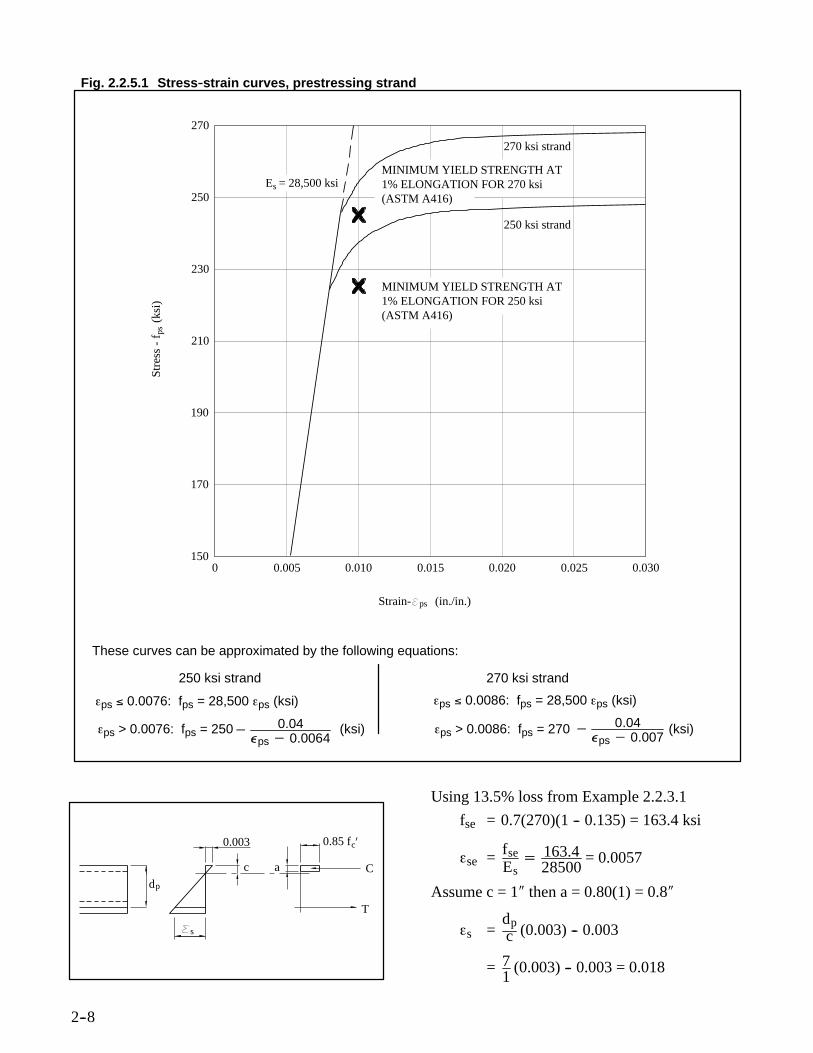
METHOD 3: Strain CompatibilityThe stress-strain diagram from Figure 11.2.5 of
the PCI Design Handbook, shown in Fig. 2.2.5.1,will be used for this example. However, the actualstress-strain curves received with strand mill re-ports should be used when available.
The concrete ultimate strain is assumed to be0.003 in/in. The method involves a trial and errorprocedure to obtain equilibrium within the sectionwhere the force in the compression block equalsthe tensile force in the steel. The equations are de-veloped from the strain diagram shown.
These curves can be approximated by the following equations:
250 ksi strand 270 ksi strand
εps ≤ 0.0076: fps = 28,500 εps (ksi)
εps > 0.0076: fps = 250 (ksi)
εps ≤ 0.0086: fps = 28,500 εps (ksi)
εps > 0.0086: fps = 270 (ksi)− 0.04Áps − 0.0064
− 0.04Áps − 0.007
1500 0.005 0.010 0.015 0.020 0.025 0.030
170
190
210
230
250
270
250 ksi strand
270 ksi strand
E = 28,500 ksis
MINIMUM YIELD STRENGTH AT1% ELONGATION FOR 270 ksi(ASTM A416)
(ASTM A416)1% ELONGATION FOR 250 ksiMINIMUM YIELD STRENGTH AT
Stre
ss -
f
(ks
i)ps
Strain- (in./in.)ps
dp
s
0.003
T
Cac
0.85 fc’
Using 13.5% loss from Example 2.2.3.1
fse = 0.7(270)(1 -- 0.135) = 163.4 ksi
εse = fseEs
= 163.428500
= 0.0057
Assume c = 1″ then a = 0.80(1) = 0.8″
εs =dpc (0.003) -- 0.003
= 71
(0.003) -- 0.003 = 0.018
2--9
εps = εse + εs
= 0.0057 + 0.018 = 0.0237
From stress-strain curve
fps = 268 ksi
T = 4(0.153)(268) = 163.8
C = 0.85(5)(0.8)(36)
= 122.4k < 163.8k
Try c = 1.3″ then a = 0.80(1.3) = 1.04″
εs = 71.30
(0.003) -- 0.003
= 0.0131
εps = 0.0131 + 0.0057 = 0.0188
From stress-strain curve
fps = 267 ksi
T = 4(0.153)(267) = 163
C = 0.85(5)(1.04)(36)
= 159k ≈ 163k
φMn = 0.9(4)(0.153)(267)7− 1.042
= 952 in-k/slab = 79.3 ft-k/slab
On occasion, conventional reinforcement isadded to a hollow core slab to locally provide add-ed flexural strength. When required, the bars areplaced in cores right after the slab is cast and con-crete is added to fill the cores with the bars. Thefollowing example illustrates the flexural strengthcalculation.
Example 2.2.5.2 Flexural Strength with BarsRepeat Example 2.2.5.1 but add 2 - #4 bars in
cores.Solution:
Use strain compatibility for strength calculationwith an effective depth of 5.5 in for the #4 bars.
Assume c = 1.53 in.
then a = 0.80(1.53) = 1.22 in
for strands
εs = 71.53
(0.003)− 0.003
= 0.0107 in/in
εps = 0.0057 + 0.0107
= 0.0164 in/in
fps = 266 ksi
for bars
εs = 5.51.53
(0.003)− 0.003
= 0.0078 in/in
yield strain = 6029000
= 0.002 in/in
T = 4(0.153)(266) + 2(0.2)(60)
= 162.8 + 24
= 186.8k
C = 0.85(5)(1.22)(36)
= 186.7k ≅ 186.8k ok
φMn = 0.9162.87− 1.222+ 245.5− 1.22
2
= 1042 in-k
= 86.8 ft-k
2.3 Shear Design
2.3.1 ACI RequirementsHollow core slabs are designed for shear ac-
cording to the same ACI Code provisions used ingeneral for prestressed members. In dry cast sys-tems, the normal practice is to not provide stirrupswhen the applied shear exceeds shear capacity be-cause of the difficulty encountered placing stir-rups in most production processes. The place-ment of stirrups in a wet cast system is certainlyeasier than in a dry cast extruded system and is aviable shear enhancement method. An alternativeused to increase shear capacity is to reduce thenumber of cores used in a given slab. This may bedone by either leaving out a core for the entirelength of a slab or by locally breaking into thecores and filling them solid while the concrete isstill in a somewhat plastic state.
The provisions for shear are found in Chapter11 of ACI 318-95. With some paraphrasing, therequirements are:Vu ≤ φVn
φ = 0.85 for shear
Vn = Vc + Vs
2--10
For the purpose of this discussion, Vs, the con-tribution of shear reinforcement, will be taken aszero. The nominal concrete shear strength may befound using equation (11-9),
Vc = 0.6 f′c + 700 VudMubwd (11-9)
when the effective prestress force is not less than40 percent of the tensile strength of the flexural re-inforcement. The term Vud/Mu shall not exceed1.0. The minimum value for Vc may be used as2 f′c bwd and the maximum value is the lesser of5 f′c bwd or the value obtained from Equation(11-12) considering reduced effective prestress inthe transfer zone.
Alternatively more refined shear calculationscan be made according to the lesser of Equations(11-10) or (11-12).
Vci = 0.6 f′c bwd+Vd +ViMcrMmax
(11-10)
Vcw = (3.5 f′c + 0.3fpc) bwd (11-12)Equation (11-10) predicts shear strength for an
inclined shear failure mode. For Equation(11-10), the following relationships are used:
Md = Unfactored self weight moment fornon-composite sections
The minimum value for Vci need not be lessthan 1.7 f′c bwd or 2 f′c bwd when the effectiveprestress force is not less than 40% of the tensilestrength of the flexural reinforcement. For equa-tions (11-10), (11-11) and (11-12), the reductionin prestressing force at the member end due totransfer must be considered. The ACI Code al-lows an assumption that prestressing force in-creases linearly from zero at the member end tofull effective prestress in a length equal to 50strand diameters.
Example 2.3.1.1 Shear Design
Using the generic hollow core cross-sectiondefined in Section 1.7, check the slab for sheargiven the following information:
Line Load: Pu = 1.4(0.800) = 1.12k/ft= (3′)(1.12) = 3.36k
Load, shear and moment diagrams for 3′ slabwidth:
1.12 x 3 = 3.36
0.188 x 3 = 0.564
k
kft
10k
k8.31
4.95k
k7.45
V
M
u
u
27.48 ft-k
49.25 ft-k
25
3
’
’
’
’
Using the more refined approach according toACI Equations (11-10) or (11-12), φVc is:
φVcw = 0.851000
3.5 5000 + 0.3fpcx (10.5)(7) (11-12)
= 15.46 + 0.0187fpc
fpc is calculated as a function of the transfer of pre-stress into the section along the span.
2--11
transfer length = 50 db = 50(1/2) = 25″with bearing length = 3″full prestress transfer is achieved 22″ fromthe face of support
Apsfse= 4(41,300)(0.70)(1 - 0.150)
x x+ 325 to x = 22″
fpc=Apsfse
A= 98294
154x+ 3
25
φVcw = 15.46 + 0.0187 98294154
x+ 325
= 15.46 + 11.96 x+ 325 to x = 22″
φVci = 0.6 50001000
10.57 +Vd +ViMcrMmax
x 0.85 (11-10)
Vd = Shear due to unfactored self weight(for non-composite section)
= 3(0.0535)252− x = 2.01 -- 0.16x
Vi = Shear due to factored loads minus Vd
Mcr = Iyb6 f′c + fpe − fd
fpe = Apsfse1A+ eyb
I
fpe = 98.294 x
1154
+3.89− 13.89
1224.5x+ 3
25
= 1.541x+ 325 ≤ 1.541 ksi
fd = flexural stress due to load used for Vd
=MdS
=
30.0535x2
25− x
314.8
= 2.01x− 0.08x2
314.8
Mcr = 314.812
x
0.424+ fpe −2.01x− 0.08x2
314.812
= 11.130 + 26.233fpe -- 2.01x + 0.8x2
Mmax = Moment due to factoredloads minus Md
Based on these definitions, φVcw, φVci, and Vu arecalculated at intervals across the span. A summa-ry is presented in Table 2.3.1.1. Figure 2.3.1.1presents the results graphically.
Alternatively, the simplified equation (11-9)might be used.
φVc = 0.850.6 5000 + 700VuMu7
x10.571000
= 2.65 + 306.1 VuMu
(Mu in in-k).
The results of this equation are also shown on Fig-ure 2.3.1.1.
At all points, Vu < φVc so shear strength is ade-quate and stirrups are not required.
2.4 Camber and DeflectionCamber is the upward deflection of a pre-
stressed member and results from the prestressingforce being eccentric from the center of gravity ofthe cross-section. Since both prestressing forceand eccentricity are established by the requireddesign load and span length, camber is a result ofthe design rather than a design parameter. There-fore, camber requirements should not be speci-fied.
Deflections are also affected by the amount ofprestressing only because prestressing establishesthe load at which a member will crack. If tensile
2--12
Fig. 2.3.1.1 Shear for Example 2.3.1.1
Distance into Span, ft
00
Shea
r, k
ips
5
10
15
20
25
1 2 3 4
Eq. (11-10)
Eq. (11-9)
Eq. (11-12)
2 f’ b d
Vu
c w
5 f’ b dc w
stresses are kept below cracking, deflections willbe independent of the prestress level.
Cambers and deflections will change with timedue to concrete creep, prestress loss and other fac-tors. The sustained compression due to the pre-stressing will cause camber growth. Balancingthis is the effect of creep on deflections due to selfweight and other sustained loads. It is this timedependent movement which, in addition to instan-taneous deflections, must be considered in the de-velopment of framing schemes and detailing.
Instantaneous cambers and deflections are pre-dictable as long as the material properties areknown. The time dependent cambers and deflec-
tions are not predictable with any degree of accu-racy and any calculation of long term movementsmust be considered to be only estimates.
This section presents calculation proceduresfor determining long term deflections. From theproducer’s standpoint, history and experiencemust be used to modify the procedures to fit the lo-cal product. From the specifier’s standpoint, theseprocedures will allow only approximate estimatesof long term effects and should be complementedwith discussions with local producers.
2.4.1 Camber
2--13
1.85 1.85
1.80 1.80
2.70 2.40
2.45 2.20
3.00 3.00
------ 2.30
Table 2.4.1 Long term multipliers6
At Erection:1. Deflection (downward) component - apply to the elastic
deflection due to the member weight at release of prestress2. Camber (upward) component - apply to the elastic camber
due to the prestress at the time of release of prestressFinal:
3. Deflection (downward) component - apply to the elasticdeflection due to the member weight at release of prestress
4. Camber (upward) component - apply to the elastic camberdue to prestress at the time of release of prestress
5. Deflection (downward) - apply to elastic deflection due tosuperimposed dead load only
6. Deflection (downward) - apply to elastic deflection causedby the composite topping
ConditionWithout
CompositeTopping
WithCompositeTopping
Hollow core slabs are produced with straightstrand patterns rather than using draped or de-pressed strands. Using (+) to indicate upwardmovement and (--) to indicate downward move-ment, net camber can be calculated as:
camber = Peℓ2
8EI− 5wℓ4
384EI
To determine initial camber, the appropriatevalues for prestress force and modulus of elastic-ity of the concrete must be used. When ultimatemoment rather than tensile stresses govern a de-sign, the initial strand stress may be reduced tomodify the anticipated camber. Additionally, slabcamber is sensitive to support point locations dur-ing storage. Camber will increase as these supportpoints move in from the slab ends.
Example 2.4.1 Initial CamberUsing the generic hollow core slab defined in
section 1.7, calculate the initial camber given thefollowing:
Solution:Estimate initial losses at 5% and use Eci = 3250
ksiPo = 0.95(0.7)(4)(41.3) = 109.9k
camber =109.93.89− 1[30.5(12)]2
832501224.5
--530.0535(30.5)41728
38432501224.5
= 1.34 -- 0.79
= 0.55″ Say 1/2″ to 3/4″ initial camberEstimating long term effects is complicated be-
cause, as time passes, the prestressing force de-creases due to losses and the modulus of elasticityof the concrete increases with concrete strengthgain. Traditionally, a creep factor of 2.0 has beenapplied to instantaneous deflections to estimatethe additional deflection due to creep. This hasbeen modified by Martin6 for prestressed con-crete. Table 2.4.1 presents suggested multipliersto determine both long term final deflections andposition at erection. It should be noted that in us-ing these multipliers, a total deflection is calcu-lated rather than the additional increment due tolong term effects.
Example 2.4.2 Long Term Camber
2--14
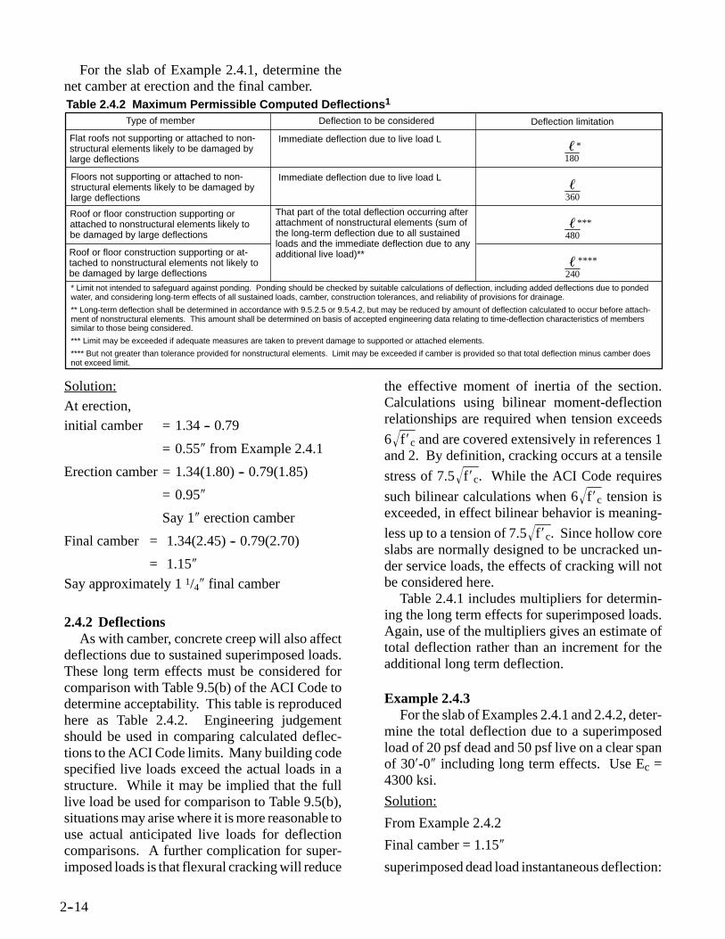
For the slab of Example 2.4.1, determine thenet camber at erection and the final camber.Table 2.4.2 Maximum Permissible Computed Deflections1
Type of member Deflection to be considered Deflection limitation
Immediate deflection due to live load L ℓ180
Floors not supporting or attached to non-structural elements likely to be damaged bylarge deflections
Immediate deflection due to live load L ℓ360
*
***
****
ℓ480
ℓ240
Roof or floor construction supporting orattached to nonstructural elements likely tobe damaged by large deflections
That part of the total deflection occurring afterattachment of nonstructural elements (sum ofthe long-term deflection due to all sustainedloads and the immediate deflection due to anyadditional live load)**Roof or floor construction supporting or at-
tached to nonstructural elements not likely tobe damaged by large deflections* Limit not intended to safeguard against ponding. Ponding should be checked by suitable calculations of deflection, including added deflections due to pondedwater, and considering long-term effects of all sustained loads, camber, construction tolerances, and reliability of provisions for drainage.
** Long-term deflection shall be determined in accordance with 9.5.2.5 or 9.5.4.2, but may be reduced by amount of deflection calculated to occur before attach-ment of nonstructural elements. This amount shall be determined on basis of accepted engineering data relating to time-deflection characteristics of memberssimilar to those being considered.
*** Limit may be exceeded if adequate measures are taken to prevent damage to supported or attached elements.
**** But not greater than tolerance provided for nonstructural elements. Limit may be exceeded if camber is provided so that total deflection minus camber doesnot exceed limit.
Flat roofs not supporting or attached to non-structural elements likely to be damaged bylarge deflections
2.4.2 DeflectionsAs with camber, concrete creep will also affect
deflections due to sustained superimposed loads.These long term effects must be considered forcomparison with Table 9.5(b) of the ACI Code todetermine acceptability. This table is reproducedhere as Table 2.4.2. Engineering judgementshould be used in comparing calculated deflec-tions to the ACI Code limits. Many building codespecified live loads exceed the actual loads in astructure. While it may be implied that the fulllive load be used for comparison to Table 9.5(b),situations may arise where it is more reasonable touse actual anticipated live loads for deflectioncomparisons. A further complication for super-imposed loads is that flexural cracking will reduce
the effective moment of inertia of the section.Calculations using bilinear moment-deflectionrelationships are required when tension exceeds6 f′c and are covered extensively in references 1and 2. By definition, cracking occurs at a tensilestress of 7.5 f′c . While the ACI Code requiressuch bilinear calculations when 6 f′c tension isexceeded, in effect bilinear behavior is meaning-less up to a tension of 7.5 f′c . Since hollow coreslabs are normally designed to be uncracked un-der service loads, the effects of cracking will notbe considered here.
Table 2.4.1 includes multipliers for determin-ing the long term effects for superimposed loads.Again, use of the multipliers gives an estimate oftotal deflection rather than an increment for theadditional long term deflection.
Example 2.4.3For the slab of Examples 2.4.1 and 2.4.2, deter-
mine the total deflection due to a superimposedload of 20 psf dead and 50 psf live on a clear spanof 30′-0″ including long term effects. Use Ec =4300 ksi.
Solution:
From Example 2.4.2
Final camber = 1.15″
superimposed dead load instantaneous deflection:
2--15
=50.023(30)4172838443001224.5
= 0.208″
Final deflection = 0.208 (3.0) = 0.62″
Instantaneous live load deflection:
=50.053(30)4172838443001224.5
= 0.52″
Final position
final camber = + 1.15″sustained dead load = -- 0.62
net camber + 0.53″live load increment = -- 0.52
+ 0.01″
For comparison to the provisions of Chapter 9of the ACI Code, when non-structural elementsare attached to the slabs, the portion of deflectionafter erection may be used for comparison.Change in camber = 1.15″ -- 0.95″ = + 0.20″Sustained dead load = -- 0.62″Instantaneous live loads = -- 0.52″
-- 0.94″When a composite topping is used, it will be
cast after a portion of the slab shrinkage has oc-curred. There will then be differential shrinkagebetween the topping and slab. This differentialcan cause additional deflection and bottom tensilestress. These effects will generally be negligible.
Example 2.4.4 Composite SlabGiven the slab of Example 2.4.3, add a 2″ com-
posite topping and recalculate deflections includ-ing the affects of differential shrinkage.Solution:
Final camber = 1.34 x 2.20 -- 0.79 x 2.40
= 1.05″
Instantaneous topping weight deflection:
=50.0253(30)4172838443001224.5
= 0.26″
Long term deflection due to topping weight
= 0.26″ (2.30) = 0.60″
Superimposed dead load deflection:
=50.023(30)4172838443002307
= 0.11″(Note: 2307 in.4 = composite moment of inertiausing a 3000 psi topping on a 5000 psi slab.)Long term dead load deflection
= 0.11(3.0) = 0.33″Instantaneous live load deflection:
= 5020
(0.11) = 0.28″
Final Position = +1.05 -- 0.60 -- 0.33 -- 0.26 =--0.14″ including instantaneous live load.Calculate increment due to differential shrinkageassuming shrinkage strain of 500 × 10--6 in/in inboth the topping and slab:
If total shrinkage = 500 × 10-6
and erection shrinkage = 250 × 10-6
differential shrinkage = 250 × 10-6
The differential shrinkage can be thought of asa prestress force from the topping where
P = Atopping (strain)(modulus)
= 36″(2″)(0.00025)(3320)
= 59.8kThe effect is lessened by concrete creep and,
using a factor of 2.30 from Table 2.4.1, reduces to:P = 59.8/2.30 = 26k
The eccentricity of this force is:e = 9″ -- 3.89″
= 5.11″
M = Pe = 26 x 5.11 = 133 in-k
downward deflection = Mℓ2
8EI
= 133(30x12)2
843002307
= 0.22″ ≅ 1/4″Considering the span used in this example and
the accuracy of the other camber and deflectioncalculations, it can be easily seen that differentialshrinkage will generally not be significant.
2.5 Composite DesignA composite, structural concrete topping is
commonly used in floor construction with hollow
2--16
core slabs. The composite action is desirable toadd stiffness and strength for gravity loads andmay also be required for load transfer within a dia-phragm. When a composite topping is used, con-sideration must be given to its strength, detailingand quality assurance.
The required compressive strength of the top-ping may be determined from the hollow core slabdesign requirements. Load tables provided by lo-cal producers will normally indicate that either a3000 psi (20.7 MPa) or 4000 psi (27.6 MPa) con-crete is required. Diaphragm requirements maynecessitate a higher strength topping concrete.
From a detailing standpoint, the primary con-sideration is that hollow core slabs will have cam-ber. If the topping is finished as a level surface, thecamber will reduce the topping thickness in themidspan region which will affect the load capacityof the slabs. With significant topping thicknessreduction, the integrity of the topping concretemay also be compromised. A preliminary slab de-sign can provide an estimate of camber and theminimum topping thickness necessary to supportthe design loads. The first option is to provide theminimum thickness topping at midspan and allowthe thickness to increase at the slab ends to main-tain a flat floor. Finish and bearing elevations canthen be set to this criteria.
A second option to minimize topping concretevolume is to allow the minimum topping thick-ness to follow the curvature of the slabs. This willresult in a finished floor with camber which maybe acceptable in some occupancies. In this option,it is important that all trades be made aware of thefinal camber as it may affect their work. Parti-tions, doorways and stairs will be particularly af-fected in this option.
When control joints are used in a structural top-ping, they should be located over the joints in theprecast units below where cracks would most nat-urally occur in the topping. At the ends of slabs,where movement will occur due to camberchanges, deflections, creep, shrinkage or elasticshortening, control joints are desirable.
Reinforcing of a topping may be required forstructural design. If not, consideration should begiven to using minimum shrinkage reinforcementfor crack control.
Since the composite topping and hollow coreslabs interact to create the final structural element,it is imperative that the topping bond well with theslabs. While the building designer may only be in-terested in the final product, the process of achiev-ing a well bonded, composite topping is very im-portant. The hollow core producer is dependenton a properly bonded topping, yet is not involvedin specifying, designing or installing the topping.The hollow core producer is responsible for sup-plying a slab that is capable of bonding with a top-ping. The installer of the topping is responsiblefor surface preparation, topping concrete mix de-sign and curing to assure proper bond.
At a minimum, the slab surface must be cleanand damp at the time of topping installation. It isrecommended that the surface be thoroughly satu-rated prior to topping placement, but all standingwater must be removed. ACI 301-967 specifiesthat a sand and cement grout be scrubbed into theslab surface ahead of topping placement. If thisprocedure is used, it is imperative that initial setnot be allowed prior to topping placement. If ini-tial set occurs, the grout can become a bond break-er. Similarly, bonding agents, which are rarelyspecified, will also act as a bond breaker if any ini-tial set occurs prior to topping placement.
The topping concrete mix and curing tech-niques will also affect bond of a composite top-ping. Curling at topping edges or joints will causelocal delamination. Curling is a result of differen-tial shrinkage between the top and bottom sur-faces of the topping. Generally, water is lost morequickly from the top surface causing additionaldrying shrinkage. This can be minimized by prop-er curing techniques and low shrinkage concrete.
Design of hollow core slabs for composite ac-tion is usually limited to a horizontal shearstrength of 80 psi (0.5 MPa) according to section17.5.2.1 of ACI 318-95. Through limited pub-lished8 and unpublished testing, the machine fin-ished surface has been found to meet the require-ments of that section. The horizontal shear checkshould be based on the shear diagram rather thanusing an average horizontal shear over the dis-tance from zero moment to maximum momentwhen checking compliance with the 80 psi limit.
Composite ties are not normally provided giv-en the difficulty and expense of installing the ties
2--17
in a machine casting operation. When the horizon-tal shear exceeds 80 psi (0.5 MPa) and compositeties are not used, the topping is considered to besuperimposed dead load on a non-composite slab.In a wet cast system, horizontal shear ties with 1/4in amplitude roughening may be used to take ad-vantage of the higher stresses allowed by ACI.
Design of a composite section is similar to thatpresented in Sections 2.2 and 2.3. The followingexample demonstrates the additional consider-ations with a composite section.
Example 2.5.1 Composite DesignUsing the generic hollow core cross-section de-fined in Section 1.7, add a 2 in structural toppingand check for the following conditions:Prestressing steel: 4-1/2″ dia., 270 ksi low relax-ation strands
for composite section, fpc is calculated at centroidof composite section
fpc = 32.6154
− 32.6(2.89)(5.24− 3.89)1224.5
= 0.108 ksi
φVcw = 0.853.5 50001000
+ 0.3(0.108)(10.5)(9)
= 22.5k > 9.8 k ok
Check inclined shear at 4 ft
Vu = 302− 4(0.223)(3)
= 7.36k
Vd = 302− 4(0.0535+ 0.025+ 0.020)(3)
= 3.25k
Vi = 7.36 -- 3.25 = 4.11k
Mu = 0.223(3)(4)302− 4
2 = 34.8 ft-k
Md = (0.0535 + 0.025 + 0.020)(3)(4)302− 4
2
= 12.25 + 3.12 = 15.37 ft-k
Mmax = 34.8 -- 15.37 = 19.43 ft-k
fpe = 101.8154
+ 101.8(2.89)(3.89)1224.5
= 1.596 ksi
fd = 12.25(12)(3.89)1224.5
+ 3.12(12)(5.24)2307
= 0.552 ksi
Mcr = 23075.246 5000
1000+ 1.596− 0.552
= 646 in-k = 53.9 ft-k
2--19
φVci = 0.850.6 50001000
(10.5)(9)+ 0.853.25+ 4.11(53.9)
19.43
= 15.86k > 7.36k ok
2--20
Fig. 2.6.1.1St
eel S
tres
s fps
sef
t f
d
Length into span
Strand Development
2.6 Strand Development
2.6.1 ACI RequirementsSection 12.9 of the ACI Code covers develop-
ment length for prestressing strands. While thetopic has received considerable discussion9-16,the ACI Code expression currently remains:
ℓd = (fps -- 2/3fse)db
A further requirement is that the developmentlength shall be doubled when bonding of a stranddoes not extend to the end of the member and theprecompressed tensile zone is allowed to be intension at service loads.
The ACI Code expression for developmentlength describes two bond mechanisms. The firstis the transfer length which is the bond length re-quired to transfer the effective prestress afterlosses, fse, to the concrete. This portion of the de-velopment length is:
ℓt = fse3
db
With fse equal to 150 ksi (1034 MPa), the trans-fer length becomes 50db, the length used for shearcalculations.
The second mechanism is for bond length afterthe steel stress increases above fse. To develop thefull design strength of the strand, fps, a bond lengthin addition to the transfer length is required. Theflexural bond length is expressed as:
ℓf = (fps -- fse)db
Figure 2.6.1.1 depicts the increase in steelstress along the development length of the strand.
Fig. 2.6.1.2
fps
d
psf req’d.greater thanf availableps
Section 12.9.2 of the ACI Code limits inves-tigation of development length to the section near-est the end of the member where full designstrength is required. In conventionally reinforcedconcrete, the rate of moment increase must beconsidered in selecting reinforcing bar sizes. Thisconsideration is also valid in prestressed concretemembers. As shown in Figure 2.6.1.2, with asteep rate of moment increase, critical sectionsmay occur in the strand development length at lessthan maximum moment.
Demand on strand strength above fse does notoccur until after flexural cracking occurs. If flex-ural cracking occurs in the transfer length, thestrand cannot accept additional stress so bond fail-ure occurs. Therefore, the limit on member flexu-ral strength in the strand transfer length is thecracking moment.
In the flexural bond length, strand stress can in-crease above fse, but not to full fps. Therefore,there is additional flexural strength above thecracking moment, but less than full nominalstrength. If flexural cracking occurs at factoredload in the flexural bond length, the maximumvalue for fps can be calculated as:
f′ps= fse +x−ℓt
ℓf(fps -- fse)
where x = the distance from the end of themember to the section of interest
The nominal moment capacity is then calculatedon the basis of this maximum strand stress.
Martin and Korkosz17 suggest that with partial-ly developed strand, the full concrete compressive
2--21
failure strain will not be achieved. A strain com-patibility analysis can be performed to determinethe concrete strain that would be consistent withf′ps and nominal strength can then be calculatedusing that strain.
When debonded strands are mixed with fullybonded strands, a similar strain compatibilityanalysis may be required in the flexural bondlength for the debonded strands. In this case,nominal strength can be calculated in two ways:1. Analyze section with all strands at the f′ps for
the debonded strands.
2. Analyze section with only fully bonded strandsat their fps and ignore the debonded strands.
The greater of the two results would predict thenominal strength of the section.
For hollow core slabs, the strain compatibilityanalysis for partially developed strand will yieldvariable results as compared to a traditional ap-proach where f′ps is used with a full concrete strainof 0.003 in/in. If f′ps is close to fse, the strain com-patibility analysis will predict moment capacity ofabout 85% of the traditional analysis. When f′ps is10% greater than fse, the difference reduces to 5%or less. The additional complexity of the straincompatibility analysis would only seem war-ranted when flexural cracking is expected near thetransfer point or when debonded strands are used.
There are several aspects of a bond length dis-cussion that are significant to hollow core slab de-sign. In many framing schemes, there will be a re-quirement to use very short slabs to fill in an area.With fully developed strands, these slabs will nor-mally have very large load capacities. However,capacity may be reduced because the strandsmight only be partially developed. For example,for a slab prestressed with 1/2″ (12.7 mm) φ, 270ksi (1860 MPa) strands with fse = 150 ksi (1034MPa) and fps = 260 ksi (1790 MPa):
ℓd = fps − 23
fsedb
= 260− 231500.5
= 80″ = 6′-8″ (2030 mm)This slab would have to be two development
lengths, or 13′-4″ (4.1 m) long in order to developits full design strength. A shorter slab would havereduced capacity.
Hollow core slab systems are often required tocarry concentrated or wall loads which may affectthe rate of moment increase near the member end.While not required by ACI, it is suggested that thetransfer length and flexural bond length regionsbe investigated for reduced capacity when the mo-ment gradient is high.
The development length equations in the ACICode are based on testing conducted with mem-bers cast with concrete having normal water-ce-ment ratios. As noted in the Commentary to theACI Code, no slump concrete requires extra pre-cautions. Hollow core slabs produced with the ex-trusion process fall into this category. As original-ly presented by Anderson and Anderson10 andreinforced by Brooks, Gerstle and Logan18, ameasure of satisfactory bond is the free end slip ofa member after it is cut to length. A limit on freeend slip expressed as:
δall =fsefsi6Es
db
has been suggested as a maximum free end strandslip for using the ACI Code development lengths.This expression approximates the strand shorten-ing that would have to occur over the transferlength. For a 1/2″ (12.7 mm) dia. strand stressedinitially to 189 ksi (1300 MPa), the free end slipshould not exceed about 3/32″ (2.4 mm) if the ACICode transfer and development lengths are to beused.
When free end slip exceeds δall, the transferlength and the flexural bond length will increase.Shear strength in the transfer length and momentcapacity in the flexural bond length will be de-creased and the length into the span where fullmoment capacity is provided will be increased.
If the free end strand slip is known from qualitycontrol measurements, the member capacity canbe evaluated with consideration of extendedtransfer and flexural bond lengths. As a functionof measured end slip, the transfer length and flex-ural bond length can be calculated for each strandas follows:
ℓt = 2δsEs/fsi
ℓf = 6δsEs(fps -- fse)/(fsifse)
Shear strength can be evaluated by substitutingthe extended transfer length for 50 db in evaluat-ing the rate of increase of prestress. Flexural
2--22
Fig. 2.6.1.3 Effect of End Slip
0.0 5.0 10.0 15.0 20.0 25.0 30.0
80.00
60.00
40.00
20.00
0.00
Mom
ent (
ft-k
)
Distance Along Member Length (ft)
Uniform LoadMoment Diagram
Moment Capacitywith 5/32" End Slip
Moment Capacitywith Normal End Slip
Distance Along Member Length (ft)
Mom
ent (
ft-k
)
(b)
Moment Capacitywith 5/32" End Slip40.00
0.0
20.00
0.00
Uniform LoadMoment Diagram
5.0 10.0
60.00
80.00
15.0
Moment Capacitywith Normal End Slip
20.0 25.0
(a)
strength calculations are affected only by the ex-tension of the strand development length and po-tential reduction of f′ps. The strain compatibilityanalysis suggested by Martin and Korkosz forsections with partially developed strand becomesmore complex as there can be variation in devel-opment lengths within a given member.
Figure 2.6.1.3 illustrates the change in momentcapacity for the generic slab of Section 1.7 fromnormal slip to 5/32 in (4 mm) slip on all strands. In(a), the span length is 30 ft (9.1 m) and there wouldbe no change in slab capacity for uniform load. In(b), the span is reduced to 25 ft (7.6 m) and it isclear that the extended development length wouldresult in reduced capacity even with uniform load.End slip in excess of normal slip has a more signif-icant effect in shorter slabs.
The following example demonstrates the use ofthe Martin and Korkosz strain compatibility anal-ysis for partially developed strand and the use offree end slip for evaluating strength. The proce-dure illustrated is also valid with normal end slipby using the appropriate transfer and bondlengths.
Example 2.6.1.1 Initial Strand SlipGiven the generic hollow core slab defined in
Section 1.7, calculate the design flexural strengthgiven the following:Prestressing steel: 4-1/2″ dia., 270 ksi low