95
PCM-7230 series PCM-7230 SBC and Evaluation Kit (Coming soon) with Windows ® CE.NET or Linux PCM-7230 User’s Manual 1
PCM-7230 series PCM-7230 SBC and Evaluation Kit (Coming soon) with Windows® CE.NET or Linux
PCM-7230 User’s Manual 1

Copyright
This document is copyrighted, © 2003. All rights are reserved. The original manufacturer reserves the right to make improvements to the products described in this manual at any time without notice.
No part of this manual may be reproduced, copied, translated or transmitted in any form or by any means without the prior written permission of the original manufacturer. Information provided in this manual is intended to be accurate and reliable. However, the original manufacturer assumes no responsibility for its use, nor for any infringements upon the rights of third parties that may result from such use.
Acknowledgements
IBM, PC/AT, PS/2 and VGA are trademarks of International Business Machines Corporation.
Intel® is trademark of Intel Corporation.
Microsoft® Windows® CE.NET is a registered trademark of Microsoft Corp.
All other product names or trademarks are properties of their respective owners.
For more information on this and other Advantech products, please visit our websites at:
http://www.advantech.com
For technical support and service, please visit our support website at:
http://eservice.advantech.com.tw/eservice/
This manual is for the PCM-7230 series products.
PCM-7230 User’s Manual 2
1st. Edition: Nov, 2003
Packing List
Before you begin installing your card, please make sure that the following materials have been shipped.
For PCM-7230 SBC series
• PCM-7230 SBC
• Advantech Software Support CD (Windows® CE.NET)
• Windows® CE.NET end user license agreement (for Windows® CE.NET version)
• PCM-7230 series Cable kit (Optional. Advantech PN: PCM-7230-CK001)
• 1 x Audio cable (Mic-in jack, line-in jack, line-out jack and two 2W speakers)
• 2 x compositive connector cables. One for video-in function and the other for Video-out function.
• 4 x DB-9 RS-232 cables
• 1 x DB-9 RS-485/232 cable
• 1 x DB-15 CRT cable
• 1 x two ports USB host cable
•1 x one port USB client cable
• 1 x RJ45 Ethernet cable
• 1 x DB-25 cable for DIO & hotkey function
• 3 x Push button cables for S/W reset, H/W reset & suspend/wakeup
PCM-7230 User’s Manual 3
function.
• 1 x power in cable with big 4-pin connector
• 1 x Power switch cable
• 1 x JTAG cable
• 1 x Null modem cable
• 1 x USB client ActiveSync cable
For PCM-7230 Evaluation Kit (Coming soon)
• PCM-7230 KIT (With SBC PCM-7230S-230CE)
• 4-COM AMI-120 module
• Plastic Stylus for touch-screen
• 19V DC/60W adaptor and power cord
•Windows® CE.NET end user license agreement (for Windows® CE.NET version)
• Advantech Software Support CD for Windows® CE.NET
• readme.txt
• Datasheet
• User manual
•Windows® CE.NET 4.1 platforms SDK for PCM-7230 (for Windows® CE.NET)
• Microsoft ActiveSync Version 3.7 install files (for Windows® CE.NET).
If any of these items are missing or damaged, contact your distributor or sales representative immediately.
PCM-7230 User’s Manual 4

For PCM-7230 Evaluation Kit Compact Version (PCM-7230-SK0CE)
Please refer to the Appendix C
• PCM-7230 SBC (Optional. Advantech PN: PCM-7230S-230CE)
• PCM-7230 series Cable kit (Optional. Advantech PN: PCM-7230-CK001)
• PCM-7230 series LCD panel kit (Optional. Advantech PN: PCM-7230-PK001)
Additional Information and Assistance
Step 1: Visit the Advantech web site at www.advantech.com/risc where you can find the latest information about the product.
Step 2: Contact your distributor, sales representative, or Advantech's customer service center for technical support if you need additional assistance. Please have the following information ready before you call:
• Product name and serial number
• Description of your peripheral attachments
• Description of your software (operating system, version, application software, etc.)
• A complete description of the problems
• The exact wording of any error messages
PCM-7230 User’s Manual 5

FCC Class A
This equipment has been tested and found to comply with the limits for a Class A digital device, pursuant to Part 15 of the FCC Rules. These limits are designed to provide reasonable protection against harmful interference when the equipment is operated in a residential environment. This equipment generates, uses, and can radiate radio frequency energy. If not installed and used in accordance with this user's manual, it may cause harmful interference to radio communications. Note that even when this equipment is installed and used in accordance with this user's manual, there is still no guarantee that interference will not occur. If this equipment is believed to be causing harmful interference to radio or television reception, this can be determined by turning the equipment on and off. If interference is occurring, the user is encouraged to try to correct the interference by one or more of the following measures:
• Reorient or relocate the receiving antenna
• Increase the separation between the equipment and the receiver
• Connect the equipment to a power outlet on a circuit different from that to which the receiver is connected
• Consult the dealer or an experienced radio/TV technician for help
Warning! HIGH VOLTAGE!!!
Please do NOT touch the inverter between main board and LCD panel with your hands or any other electric conductors.
Warning! Any changes or modifications made to the equipment which are not expressly approved by the relevant standards authority could void your authority to operate the equipment.
Warning! Input voltage rated 8V~28V DC for PCM-7230 series SBC.
PCM-7230 User’s Manual 6

Packing: please carry the unit with both hands, handle with care Our European representative:
Advantech Europe GmbH
Kolberger Straße 7
D-40599 Düsseldorf, Germany
Tel: 49-211-97477350
Fax: 49-211-97477300
Maintenance: to properly maintain and clean
the surfaces, use only approved products or
clean with a dry applicator
PCM-7230 User’s Manual 7

Safety Instructions
1. Read these safety instructions carefully.
2. Keep this User's Manual for later reference.
3. Disconnect this equipment from any AC outlet before cleaning. Use a damp cloth. Do not use liquid or spray detergents for cleaning.
4. For plug-in equipment, the power outlet socket must be located near the equipment and must be easily accessible.
5. Keep this equipment away from humidity.
6. Put this equipment on a reliable surface during installation. Dropping it or letting it fall may cause damage.
7. Make sure the voltage of the power source is correct before connecting the equipment to the power outlet.
8. Position the power cord so that people cannot step on it. Do not place anything over the power cord.
9. All cautions and warnings on the equipment should be noted.
10. If the equipment is not used for a long time, disconnect it from the power source to avoid damage by transient overvoltage.
11. Never pour any liquid into an opening. This may cause fire or electrical shock.
12. If one of the following situations arises, get the equipment checked by service personnel:
a. The power cord or plug is damaged.
b. Liquid has penetrated into the equipment.
c. The equipment has been exposed to moisture.
d. The equipment does not work well, or you cannot get it to work according to the user's manual.
PCM-7230 User’s Manual 8

e. The equipment has been dropped and damaged.
f. The equipment has obvious signs of breakage.
13. DO NOT LEAVE THIS EQUIPMENT IN AN ENVIRONMENT WHERE THE STORAGE TEMPERATURE MAY GO BELOW -20° C (-4° F) OR ABOVE 60° C (140° F). THIS COULD DAMAGE THE EQUIPMENT. THE EQUIPMENT SHOULD BE IN A CONTROLLED ENVIRONMENT. BUT SPECIAL TEMPERATURE PRODUCTS COULD BE EXCLUDED.
14. CAUTION: DANGER OF EXPLOSION IF BATTERY IS INCORRECTLY REPLACED.REPLACE ONLY WITH THE SAME OR EQUIVALENT TYPE RECOMMENDED BY THE MANUFACTURER, DISCARD USED BATTERIES ACCORDING TO THE MANUFACTURER'S INSTRUCTIONS.
15. Caution: HIGH VOLTAGE!!! DO NOT touch the inverter board between main board and LCD panel.
The sound pressure level at the operator's position according to IEC 704-1:1982 is no more than 70 dB (A).
DISCLAIMER: This set of instructions is given according to IEC 704-1. Advantech disclaims all responsibility for the accuracy of any statements contained herein.
PCM-7230 User’s Manual 9

CHAPTER
1 General Information
This chapter gives background
Information of the 3.5” Biscuit
PCM-7230 Evaluation Kit.
Sections include:
• Introduction
• Specification
• Safety Precautions
• PCM-7230 Series
PCM-7230 User’s Manual 10

1.1 Introduction
Functionalities-certified, Fast, and Flexible Solution Platform Based On Intel® XScaleTM Technology
The PCM-7230 is designed as a solution board, using Intel® PXA255 processor based on Intel® XScaleTM technology, which is a complete 32-bit, up to 400 MHz speed SoC engine. It provides customers a high performance board subsystem based on Intel® XScaleTM technology with characters of ready-to-run, compact, and easy-to-expansion in order to meet customers’ versatile needs. With the flexible I/O interfaces and complete hardware and software solutions, the PCM-7230 is a fast time-to-market platform for customers to develop their applications and products easily without considering system integration.
The PCM-7230 Evaluation Kit is a complete system designed for customers to evaluate the PCM-7230. It integrates all solutions developers need, based on the PCM-7230 board, into a package that provides customers an effortless system platform for project evaluation, application development, and solution feasibility testing that decreases lead-time and lowers initial expense. The PCM-7230 Evaluation Kit has already integrated complete certified functional peripherals in a battery-powered pack under Windows® CE.NET SDK, making project development and implementation becomes an easy and risk-free way at the starting point.
Including all necessary cables, power core, and Support CD, the Evaluation Kit also contains one 800*600 LCD panel, 2000 mAh (4S1P) Li- ion battery pack and one 4-COM AMI-120 (ARM Module Interface) module. All bundled parts/components including the PCM-7230 main board arrive fully tested and certified in production-ready condition. All functionalities have been certified completely and can be leveraged to customized needs for different hardware configurations and system optimization based on the customer’s request.
Customizes and expands your versatile needs easily -- AMI-120 interface
Through the Advantech’s unique open expansion interface AMI-120, ARM Module Interface, customers could expand functionality easily with a custom-made way similar to PC/104 in x86 platforms. With this AMI-120 interface, customers can not only expand products’ functionalities easily, but develop various products based on the PCM-7230 via AMI-120 modules with
PCM-7230 User’s Manual 11
different functionalities. Users using the PCM-7230 can design their own AMI-120 module after receiving license agreement from Advantech or cooperate with Advantech for a customized AMI-120 module based on an ODM project.
1.2 The PCM-7230 Evaluation Kit Specifications
The PCM-7230 Evaluation Kit is consisted of
(1) The PCM-7230 main board integrated with Windows® CE.NET: Intel® PXA255 processor running at 400 MHz, 64 MB SDRAM on board, and a 32 MB flash on Memory Module;
(2) LCD panel, touch-screen, and inverter;
(3) Power system and adapter;
(4) AMI-120 solution module: 4-COM AMI-120 module;
(5) Cable kit( Optional for PCM-7230 series SBC. Advantech PN : PCM-7230-CK001 );
(6) Advantech Software Support CD for Windows® CE.NET;
(7) Windows® CE.NET end user license agreement (for Windows® CE.NET version only).
PCM-7230 User’s Manual 12
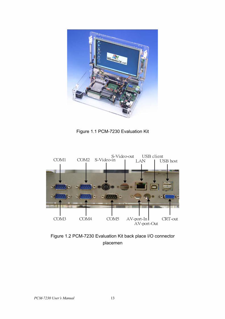
Figure 1.1 PCM-7230 Evaluation Kit
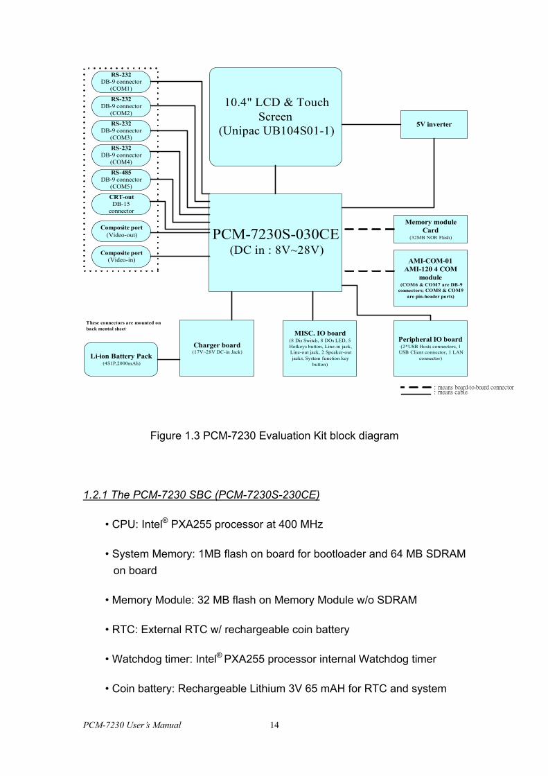
COM1 COM2 S-Video-inS-Video-out
LAN
COM3
USB clientUSB host
COM4 COM5 AV-port-InAV-port-Out
CRT-out
Figure 1.2 PCM-7230 Evaluation Kit back place I/O connector placemen
PCM-7230 User’s Manual 13
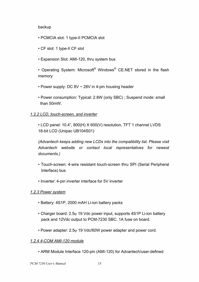
PCM-7230S-030CE(DC in : 8V~28V)
Peripheral IO board(2*USB Hosts connectors, 1
USB Client connector, 1 LANconnector)
MISC. IO board(8 Dis Switch, 8 DOs LED, 5Hotkeys button, Line-in jack,Line-out jack, 2 Speaker-outjacks, System function key
button)
10.4" LCD & TouchScreen
(Unipac UB104S01-1)5V inverter
RS-232DB-9 connector
(COM1)
RS-232DB-9 connector
(COM2)
RS-232DB-9 connector
(COM3)
RS-232DB-9 connector
(COM4)
RS-485DB-9 connector
(COM5)
CRT-outDB-15
connector
Composite port(Video-in)
Composite port(Video-out)
Memory moduleCard
(32MB NOR Flash)
: means cable: means board-to-board connector
AMI-COM-01AMI-120 4 COM
module(COM6 & COM7 are DB-9
connectors; COM8 & COM9are pin-header ports)
These connectors are mounted onback mental sheet
Charger board(17V~28V DC-in Jack)
Li-ion Battery Pack(4S1P,2000mAh)
Figure 1.3 PCM-7230 Evaluation Kit block diagram
1.2.1 The PCM-7230 SBC (PCM-7230S-230CE)
• CPU: Intel® PXA255 processor at 400 MHz
• System Memory: 1MB flash on board for bootloader and 64 MB SDRAM on board
• Memory Module: 32 MB flash on Memory Module w/o SDRAM
• RTC: External RTC w/ rechargeable coin battery
• Watchdog timer: Intel® PXA255 processor internal Watchdog timer
• Coin battery: Rechargeable Lithium 3V 65 mAH for RTC and system
PCM-7230 User’s Manual 14
backup
• PCMCIA slot: 1 type-II PCMCIA slot
• CF slot: 1 type-II CF slot
• Expansion Slot: AMI-120, thru system bus
• Operating System: Microsoft® Windows® CE.NET stored in the flash memory
• Power supply: DC 8V ~ 28V in 4-pin housing header
• Power consumption: Typical: 2.8W (only SBC) ; Suspend mode: small than 50mW.
1.2.2 LCD, touch-screen, and inverter
• LCD panel: 10.4”, 800(H) X 600(V) resolution, TFT 1 channel LVDS 18-bit LCD (Unipac UB104S01)
(Advantech keeps adding new LCDs into the compatibility list. Please visit Advantech website or contact local representatives for newest documents.)
• Touch-screen: 4-wire resistant touch-screen thru SPI (Serial Peripheral Interface) bus
• Inverter: 4-pin inverter interface for 5V inverter
1.2.3 Power system
• Battery: 4S1P, 2000 mAH Li-ion battery packs
• Charger board: 2.5ϕ 19 Vdc power input, supports 4S1P Li-ion battery pack and 12Vdc output to PCM-7230 SBC. 1A fuse on board.
• Power adapter: 2.5ϕ 19 Vdc/60W power adapter and power cord.
1.2.4 4-COM AMI-120 module
• ARM Module Interface 120-pin (AMI-120) for Advantech/user-defined
PCM-7230 User’s Manual 15
module
• 4x 9-pin full-function transceiver level RS-232
1.2.5 Cable kit (Optional for PCM-7230 series SBC)
• 1 x Audio cable (Mic-in jack, line-in jack, line-out jack and two 2W speakers)
• 2 x compositive connector cables. One for video-in function and the other for Video-out function.
• 4 x DB-9 RS-232 cables
• 1 x DB-9 RS-485/232 cable
• 1 x DB-15 CRT cable
• Video-in Composite port connector x 1
• Video-out Composite port connector x 1
• 1 x two ports USB host cable
•1 x one port USB client cable
• 1 x RJ45 Ethernet cable
• 1 x DB-25 cable for DIO & hotkey function
• 3 x Push button cables for S/W reset, H/W reset & suspend/wakeup function.
• 1 x power in cable with big 4-pin connector
• 1 x Power switch cable
• 1 x JTAG cable
• 1 x Null modem cable
PCM-7230 User’s Manual 16
• 1 x USB client ActiveSync cable (for users link PCM-7230 with PC by USB client port)
1.2.7 Advantech Software Support CD
• ActiveSync Install Program
• Windows® CE.NET 4.1 platforms SDK for PCM-7230 (for Windows® CE.NET)
• PCM-7230 User Manual
• PCM-7230 datasheet
• PCM-7230 Evaluation Kit datasheet
• Readme.txt
1.2.8 Environmental
• Operating temperature: 0 ~ 60° C (32 ~ 140° F) fanless operation
• Storage temperature: -20 ~ 70° C (4 ~ 158°F)
• Operating humidity: 0 ~ 90 % relative humidity, non-condensing
1.2.9 Dimensions for PCM-7230 Evaluation Kit
• PCM-7230 SBC Dimensions (L x W x H): 145 mm x 102 mm x 21.1 mm
• PCM-7230 Evaluation Kit Dimensions (L x W x H): 291mm x 209mm x 84mm
1.2.10 Windows® CE.NET license agreement (for Windows® CE.NET version only)
PCM-7230 User’s Manual 17

1.3 Safety Precautions
The following sections tell how to make each connection. In most cases, you will simply need to connect a standard cable. All of the connector pin assignments are shown in Appendix A.
Caution! Always ground yourself to remove any static electric charge before touching the PCM-7230-0K0CE. Modern electronic devices are very sensitive to static electric charges. Use a grounding wrist strap at all times. Place all electronic components on a static-dissipative surface or in a static-shielded bag.
Caution!!! HIGH VOLTAGE!!!
Do NOT touch the inverter between main board and LCD panel with your hand or any electric conductors.
PCM-7230 User’s Manual 18
1.4 PCM-7230 Series
PCM-7230S-030CE: Intel® PXA255 processor at 400 MHz, 64 MB SDRAM on board, W/O Memory Module and Windows® CE.NET.
PCM-7230S-230CE: Intel® PXA255 processor at 400 MHz, 64 MB SDRAM on board, with Memory Module (32 MB Flash/ 0 MB SDRAM) and Windows® CE.NET.
PCM-7230-0K0CE: PCM-7230 Evaluation Kit system based on PCM- 7230S-230CE.
Advantech welcomes ODM projects for depopulated, configurable and customized specifications. You can serf to www.advantech.com/risc for more detail about ODM project and related forms download.
PCM-7230 User’s Manual 19

CHAPTER
2 Getting Start
This chapter provides brief
instructions for operating the
PCM-7230 Evaluation Kit. (Coming soon)
Sections include:
• Quick Starting
PCM-7230 User’s Manual 20
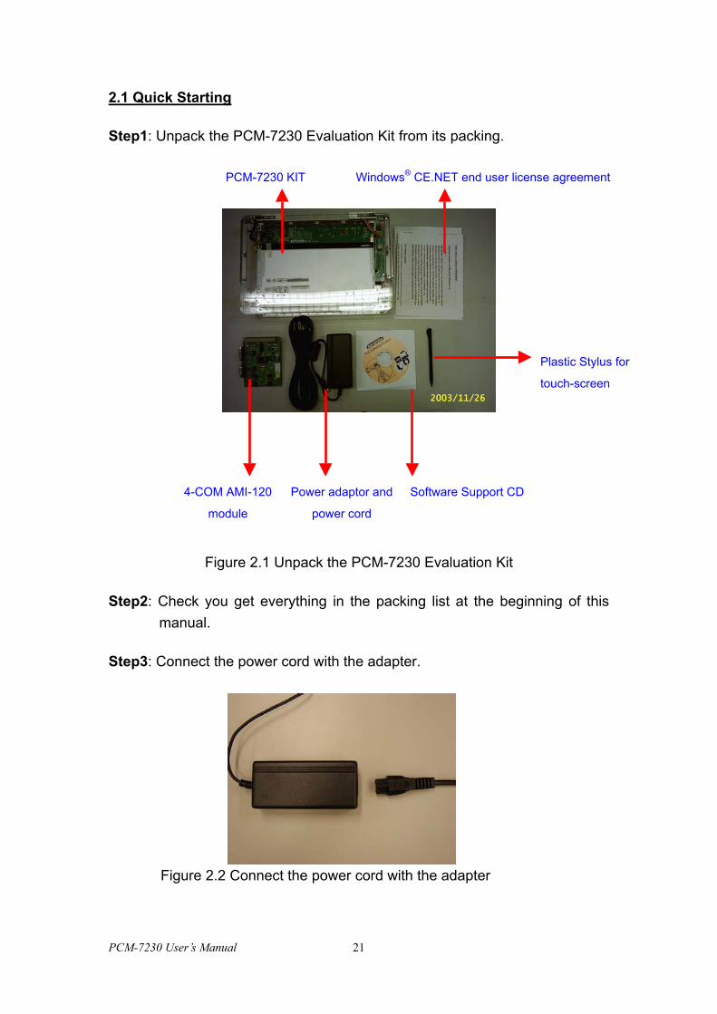
2.1 Quick Starting
Step1: Unpack the PCM-7230 Evaluation Kit from its packing.
Windows® CE.NET end user license agreementPCM-7230 KIT
Figure 2.1 Unpack the PCM-7230 Evaluation Kit
Step2: Check you get everything in the packing list at the beginmanual.
Step3: Connect the power cord with the adapter.
Figure 2.2 Connect the power cord with the adapter
PCM-7230 User’s Manual 21
Plastic Stylus for
touch-screen
Power adaptor and
power cord
4-COM AMI-120
module
Software Support CD
ning of this
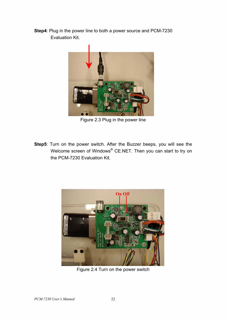
Step4: Plug in the power line to both a power source and PCM-7230 Evaluation Kit.
Figure 2.3 Plug in the power line
Step5: Turn on the power switch. After the Buzzer beeps, you will see the Welcome screen of Windows® CE.NET. Then you can start to try on the PCM-7230 Evaluation Kit.
On Off
Figure 2.4 Turn on the power switch
PCM-7230 User’s Manual 22
Figure 2.5 Welcome
NOTE: The Li-ion battery is charged when you connect the PCM-7230 Evaluation Kit to a power source. The Li-ion battery can last about 2 hours without being charged.
PCM-7230 User’s Manual 23
CHAPTER
3 Hardware Functionality
This chapter details hardware’s
setting and functionality in the
PCM-7230 Evaluation Kit.
Sections include:
• The PCM-7230 SBC
• 4-COM AMI-120 module
• LCD and touch-screen
• Power system
PCM-7230 User’s Manual 24
This chapter will detail hardware setting and functionality in the PCM-7230 Development Kit. Following will introduce (1) PCM-7230 SBC; (2) 4-COM AMI-120 module; (3) LCD and touch-screen; (4) Power system.
3.1 PCM-7230 SBC
The PCM-7230 SBC is a 3.5” (145mm x 102 mm x 21.1mm) single board computer with the Intel® PXA255 processor running at 400 MHz. The milli-watt power consumption by its kernel makes the PCM-7230 suitable for power conscious applications. With the expandable Memory Module and abundant I/O ports and interfaces, the PCM-7230 SBC is cost-effective and flexible solution for customers. The AMI-120 expansion bus, a unique standard interface for ARM-based processor defined by Advantech, lets customers expand the functionality of PCM-7230 easily by Advantech’s or user-defined module according to their needs. Besides, the PCM-7230 series offer customers variety optional specifications and solutions, providing a RISC hardware platform and fast time-to-market benefit to customers.
There are two type standard PCM-7230 SBCs, the PCM-7230S-030CE and the PCM-7230S-230CE. The PCM-7230S-230CE, the same SBC installed in the PCM-7230 Evaluation Kit, is a full-function version SBC for PCM-7230. The PCM-7230S-030CE takes off the Memory Module from the PCM-7230S-230CE. Therefore there is only 1MB on-board Flash for bootloader in the PCM-7230S-030CE. Customers who boot their application from CF card thru CF or PCMCIA slot may order this PCM-7230S-030CE because they don’t need Memory Module. Besides these two type SBCs, Advantech also offers customers another solution for customized specifications thru ODM projects. Customers can have their own PCM-7230 SBCs with specific specifications in order to achieve best performance-to-cost ratio.
PCM-7230 User’s Manual 25
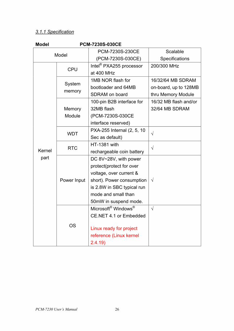
3.1.1 Specification
Model PCM-7230S-030CE
Model PCM-7230S-230CE
(PCM-7230S-030CE) Scalable
Specifications
CPU Intel® PXA255 processor at 400 MHz
200/300 MHz
System memory
1MB NOR flash for bootloader and 64MB SDRAM on board
16/32/64 MB SDRAM on-board, up to 128MB thru Memory Module
Memory Module
100-pin B2B interface for 32MB flash (PCM-7230S-030CE interface reserved)
16/32 MB flash and/or 32/64 MB SDRAM
WDT PXA-255 Internal (2, 5, 10 Sec as default)
√
RTC HT-1381 with rechargeable coin battery
√
Power Input
DC 8V~28V, with power protect(protect for over voltage, over current & short). Power consumption is 2.8W in SBC typical run mode and small than 50mW in suspend mode.
√
Kernel part
OS
Microsoft® Windows® CE.NET 4.1 or Embedded
Linux ready for project reference (Linux kernel 2.4.19)
√
PCM-7230 User’s Manual 26
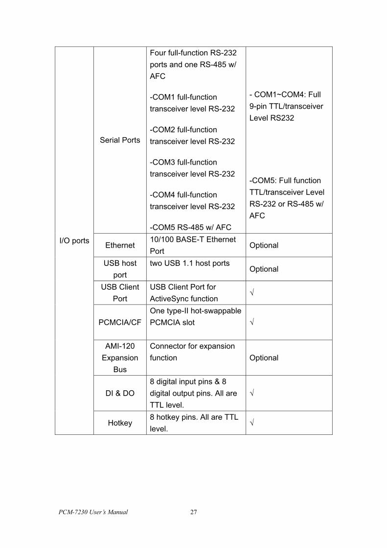
Serial Ports
Four full-function RS-232 ports and one RS-485 w/ AFC
-COM1 full-function transceiver level RS-232
-COM2 full-function transceiver level RS-232
-COM3 full-function transceiver level RS-232
-COM4 full-function transceiver level RS-232
-COM5 RS-485 w/ AFC
- COM1~COM4: Full 9-pin TTL/transceiver Level RS232
-COM5: Full function TTL/transceiver Level RS-232 or RS-485 w/ AFC
Ethernet 10/100 BASE-T Ethernet Port
Optional
USB host port
two USB 1.1 host ports Optional
USB Client Port
USB Client Port for ActiveSync function
√
PCMCIA/CF One type-II hot-swappable PCMCIA slot √
AMI-120 Expansion
Bus
Connector for expansion function Optional
DI & DO 8 digital input pins & 8 digital output pins. All are TTL level.
√
I/O ports
Hotkey 8 hotkey pins. All are TTL level.
√
PCM-7230 User’s Manual 27
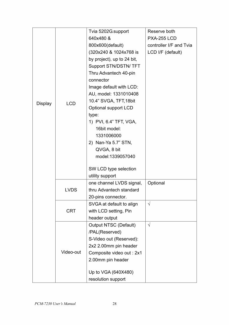
LCD
Tvia 5202G.support 640x480 & 800x600(default) (320x240 & 1024x768 is by project), up to 24 bit, Support STN/DSTN/ TFT Thru Advantech 40-pin connector Image default with LCD: AU, model: 1331010408 10.4” SVGA, TFT,18bit Optional support LCD type: 1) PVI, 6.4” TFT, VGA,
16bit model: 1331006000
2) Nan-Ya 5.7” STN, QVGA, 8 bit model:1339057040
SW LCD type selection utility support
Reserve both PXA-255 LCD controller I/F and Tvia LCD I/F (default)
LVDS one channel LVDS signal, thru Advantech standard 20-pins connector.
Optional
CRT SVGA at default to align with LCD setting, Pin header output
√
Display
Video-out
Output NTSC (Default) /PAL(Reserved) S-Video out (Reserved): 2x2 2.00mm pin header Composite video out : 2x1 2.00mm pin header
Up to VGA (640X480) resolution support
√
PCM-7230 User’s Manual 28
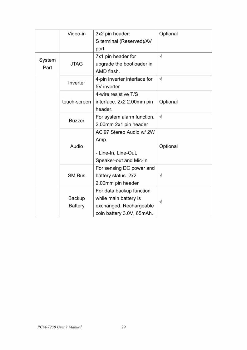
Video-in 3x2 pin header: S terminal (Reserved)/AV port
Optional
JTAG 7x1 pin header for upgrade the bootloader in AMD flash.
√
Inverter 4-pin inverter interface for 5V inverter
√
touch-screen 4-wire resistive T/S interface. 2x2 2.00mm pin header.
Optional
Buzzer For system alarm function. 2.00mm 2x1 pin header
√
Audio
AC’97 Stereo Audio w/ 2W Amp.
- Line-In, Line-Out, Speaker-out and Mic-In
Optional
SM Bus For sensing DC power and battery status. 2x2 2.00mm pin header
√
System Part
Backup Battery
For data backup function while main battery is exchanged. Rechargeable coin battery 3.0V, 65mAh.
√
PCM-7230 User’s Manual 29
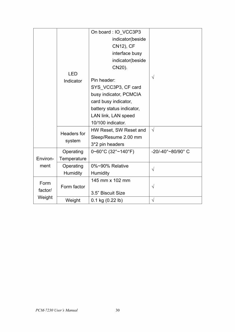
LED Indicator
On board : IO_VCC3P3 indicator(beside CN12), CF interface busy indicator(beside CN20).
Pin header: SYS_VCC3P3, CF card busy indicator, PCMCIA card busy indicator, battery status indicator, LAN link, LAN speed 10/100 indicator.
√
Headers for system
HW Reset, SW Reset and Sleep/Resume 2.00 mm 3*2 pin headers
√
Operating Temperature
0~60°C (32°~140°F) -20/-40°~80/90° C Environ-
ment Operating Humidity
0%~90% Relative Humidity
√
Form factor 145 mm x 102 mm
3.5” Biscuit Size √
Form factor/ Weight Weight 0.1 kg (0.22 lb) √
PCM-7230 User’s Manual 30
Buzzer
RTCHT1381
8 Digital Inputs and 8Digital Outputs
or 64 matrixkeypads(hot keys)
SM Bus forBattery Monitor
1 USB Client Port
HW reset, SW resetand Sleep/Resume
Pin Header
5 LEDs indicating pinheader for Power,
Ethernet, PCMCIA/CFbusy, battery status,
docking status)
1 MB AMDNOR Flash
100 pin BtoB MemoryModule interface
1 TYPE-IIPCMCIA Slot
1 TYPE-II CF Slot
AMI-120Expansion Bus with
Buffer
8 Hotkeys
DC-in 8V ~ 28VPower protect circuit(Over voltage, Over
current, power electricpole reverse)
4-wire resistiveTouch Screen
interfaceADS7846
ARM Bus
Coin battery
16C950
16C950
2 USB Host PortsPhilips ISP1160
10/100 BASE-TEthernetDM9000
AC’97 CodecALC201 and 2
Watt Amp.
Audio interface(Line-in, Line-out,
Mic-in, Speakerout )
64 MBSDRAM
Display ChipTVIA 5202
CRT-out
Video-out(Composite port)
LVDS out W/ 20pin conn.
Video-in port(Composite port)
A/D SA7114
CPLD
Buffer and Powercontrol
Full-function RS-232(COM1)
Transceiver Level
Full-function RS-232(COM2)
Transceiver Level
Full-function RS-232(COM 3)
Transceiver Level
Full-function RS-232(COM4)
Transceiver Level
RS485(COM5)
MAX3243
MAX3243
MAX3243
MAX3243
ADM3485
Transfomer
Memory modulewith 32MB Intel
Strata Flash
LCD signal buffer(3V/5V)
Contrast circuit
Brightness circuitInverter conn.8MB SDRAM
LCD out 40 pinconn.
From CPLD
CPU PXA255 400MHz
From CPLD
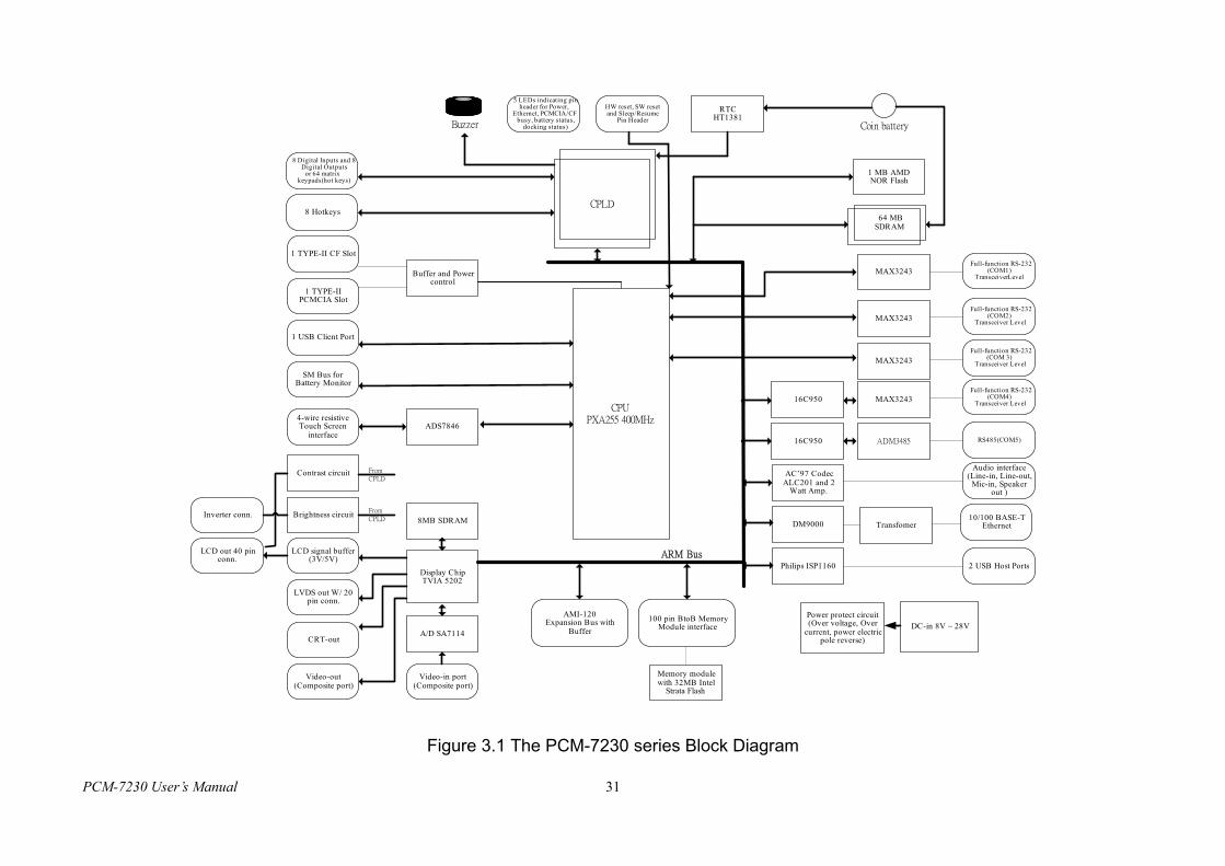
Figure 3.1 The PCM-7230 series Block Diagram
PCM-7230 User’s Manual 31
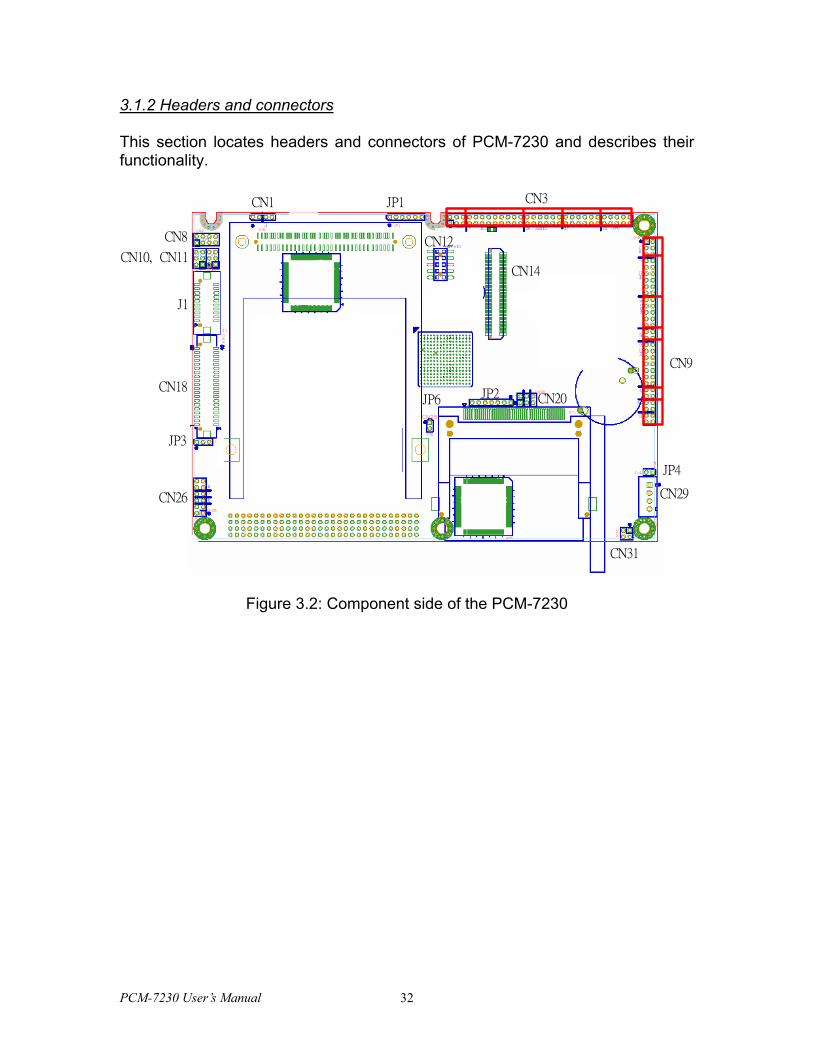
3.1.2 Headers and connectors
This section locates headers and connectors of PCM-7230 and describes their functionality.
CN9
CN3
CN12
JP1
CN14
JP4
CN29
CN31
CN20JP2
CN1
CN8
CN10, CN11
J1
CN18
CN26
JP6
JP3
Figure 3.2: Component side of the PCM-7230
PCM-7230 User’s Manual 32
BT_H
CN32(AMI-120)
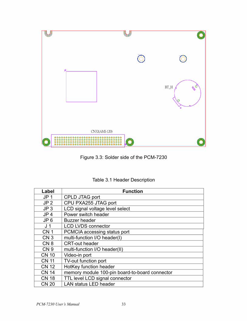
Figure 3.3: Solder side of the PCM-7230
Table 3.1 Header Description
Label Function JP 1 CPLD JTAG port JP 2 CPU PXA255 JTAG port JP 3 LCD signal voltage level select JP 4 Power switch header JP 6 Buzzer header J 1 LCD LVDS connector
CN 1 PCMCIA accessing status port CN 3 multi-function I/O header(I) CN 8 CRT-out header CN 9 multi-function I/O header(II) CN 10 Video-in port CN 11 TV-out function port CN 12 HotKey function header CN 14 memory module 100-pin board-to-board connector CN 18 TTL level LCD signal connector CN 20 LAN status LED header
PCM-7230 User’s Manual 33
CN 25 type II CF slot CN 26 Inverter signals header CN 29 Power-in connector CN 31 SM bus port CN 32 AMI-120 expansion bus connector*
*about AMI-120 bus pin define, please check the Appendix.
3.1.3 Headers and connectors pin definition
Because the board size limitation & wants to keep the flexible of I/O connector placement,
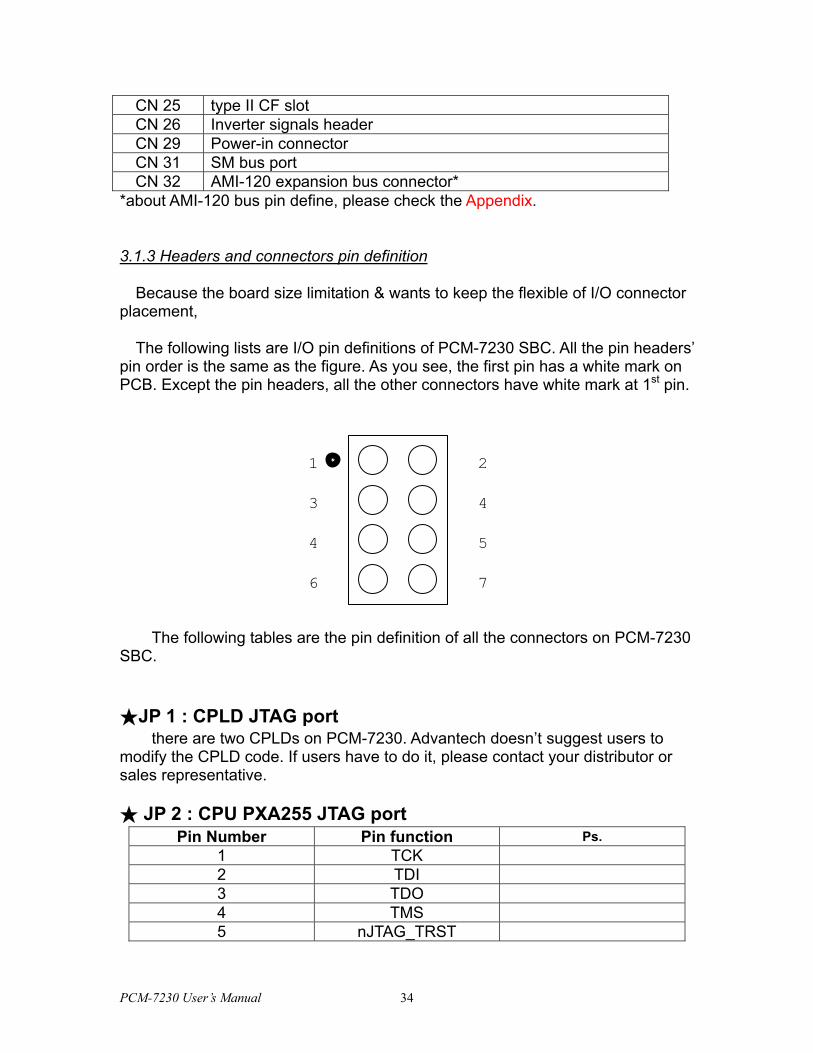
The following lists are I/O pin definitions of PCM-7230 SBC. All the pin headers’
pin order is the same as the figure. As you see, the first pin has a white mark on PCB. Except the pin headers, all the other connectors have white mark at 1st pin.
3 4
4 5
6 7
21
The following tables are the pin definition of all the connectors on PCM-7230 SBC. ★JP 1 : CPLD JTAG port
there are two CPLDs on PCM-7230. Advantech doesn’t suggest users to modify the CPLD code. If users have to do it, please contact your distributor or sales representative. ★ JP 2 : CPU PXA255 JTAG port
Pin Number Pin function Ps. 1 TCK 2 TDI 3 TDO 4 TMS 5 nJTAG_TRST
PCM-7230 User’s Manual 34
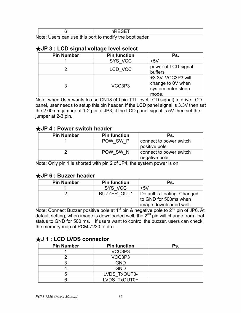
6 nRESET Note: Users can use this port to modify the bootloader. ★JP 3 : LCD signal voltage level select
Pin Number Pin function Ps. 1 SYS_VCC +5V
2 LCD_VCC power of LCD-signal buffers
3 VCC3P3
+3.3V. VCC3P3 will change to 0V when system enter sleep mode.
Note: when User wants to use CN18 (40 pin TTL level LCD signal) to drive LCD panel, user needs to setup this pin header. If the LCD panel signal is 3.3V then set the 2.00mm jumper at 1-2 pin of JP3; if the LCD panel signal is 5V then set the jumper at 2-3 pin. ★JP 4 : Power switch header
Pin Number Pin function Ps. 1 POW_SW_P connect to power switch
positive pole 2 POW_SW_N connect to power switch
negative pole Note: Only pin 1 is shorted with pin 2 of JP4, the system power is on. ★JP 6 : Buzzer header
Pin Number Pin function Ps. 1 SYS_VCC +5V 2 BUZZER_OUT* Default is floating. Changed
to GND for 500ms when image downloaded well.
Note: Connect Buzzer positive pole at 1st pin & negative pole to 2nd pin of JP6. At default setting, when image is downloaded well, the 2nd pin will change from float status to GND for 500 ms. If users want to control the buzzer, users can check the memory map of PCM-7230 to do it. ★J 1 : LCD LVDS connector
Pin Number Pin function Ps. 1 VCC3P3 2 VCC3P3 3 GND 4 GND 5 LVDS_TxOUT0- 6 LVDS_TxOUT0+
PCM-7230 User’s Manual 35
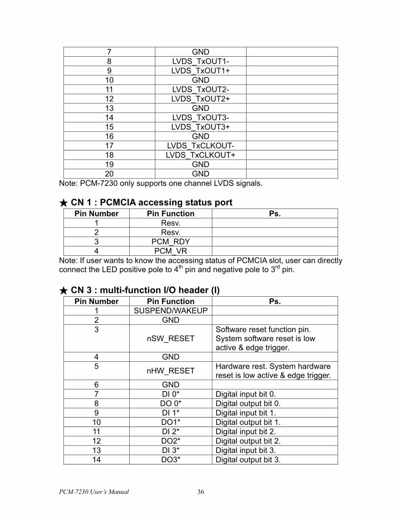
7 GND 8 LVDS_TxOUT1- 9 LVDS_TxOUT1+
10 GND 11 LVDS_TxOUT2- 12 LVDS_TxOUT2+ 13 GND 14 LVDS_TxOUT3- 15 LVDS_TxOUT3+ 16 GND 17 LVDS_TxCLKOUT- 18 LVDS_TxCLKOUT+ 19 GND 20 GND
Note: PCM-7230 only supports one channel LVDS signals. ★ CN 1 : PCMCIA accessing status port
Pin Number Pin Function Ps. 1 Resv. 2 Resv. 3 PCM_RDY 4 PCM_VR
Note: If user wants to know the accessing status of PCMCIA slot, user can directly connect the LED positive pole to 4th pin and negative pole to 3rd pin. ★ CN 3 : multi-function I/O header (I)
Pin Number Pin Function Ps. 1 SUSPEND/WAKEUP 2 GND 3
nSW_RESET Software reset function pin. System software reset is low active & edge trigger.
4 GND 5 nHW_RESET Hardware rest. System hardware
reset is low active & edge trigger. 6 GND 7 DI 0* Digital input bit 0. 8 DO 0* Digital output bit 0. 9 DI 1* Digital input bit 1.
10 DO1* Digital output bit 1. 11 DI 2* Digital input bit 2. 12 DO2* Digital output bit 2. 13 DI 3* Digital input bit 3. 14 DO3* Digital output bit 3.
PCM-7230 User’s Manual 36
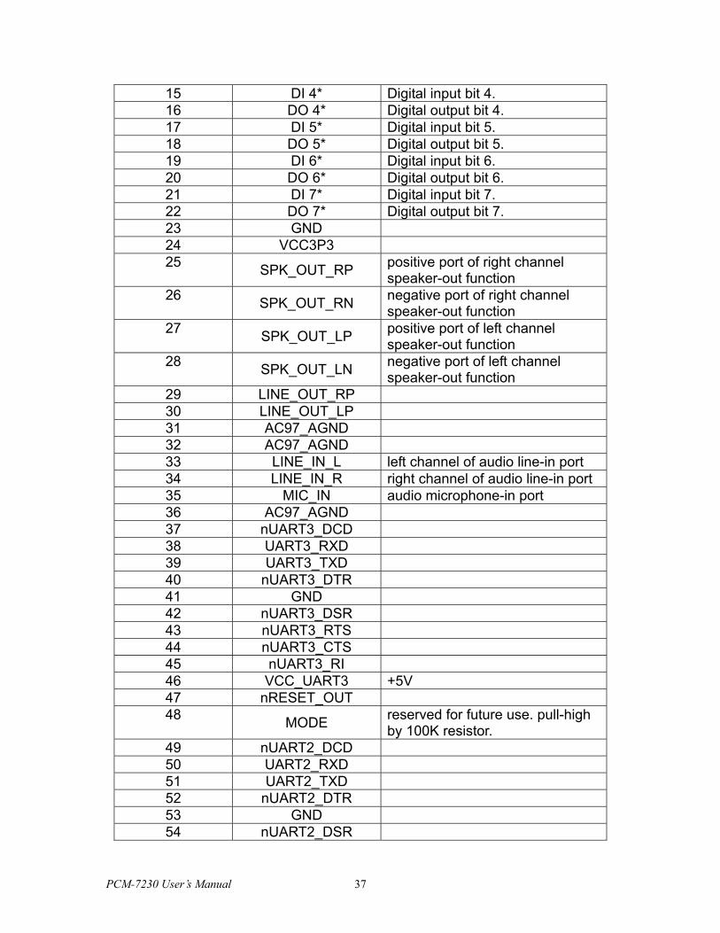
15 DI 4* Digital input bit 4. 16 DO 4* Digital output bit 4. 17 DI 5* Digital input bit 5. 18 DO 5* Digital output bit 5. 19 DI 6* Digital input bit 6. 20 DO 6* Digital output bit 6. 21 DI 7* Digital input bit 7. 22 DO 7* Digital output bit 7. 23 GND 24 VCC3P3 25 SPK_OUT_RP positive port of right channel
speaker-out function 26 SPK_OUT_RN negative port of right channel
speaker-out function 27 SPK_OUT_LP positive port of left channel
speaker-out function 28 SPK_OUT_LN negative port of left channel
speaker-out function 29 LINE_OUT_RP 30 LINE_OUT_LP 31 AC97_AGND 32 AC97_AGND 33 LINE_IN_L left channel of audio line-in port 34 LINE_IN_R right channel of audio line-in port 35 MIC_IN audio microphone-in port 36 AC97_AGND 37 nUART3_DCD 38 UART3_RXD 39 UART3_TXD 40 nUART3_DTR 41 GND 42 nUART3_DSR 43 nUART3_RTS 44 nUART3_CTS 45 nUART3_RI 46 VCC_UART3 +5V 47 nRESET_OUT 48 MODE reserved for future use. pull-high
by 100K resistor. 49 nUART2_DCD 50 UART2_RXD 51 UART2_TXD 52 nUART2_DTR 53 GND 54 nUART2_DSR
PCM-7230 User’s Manual 37
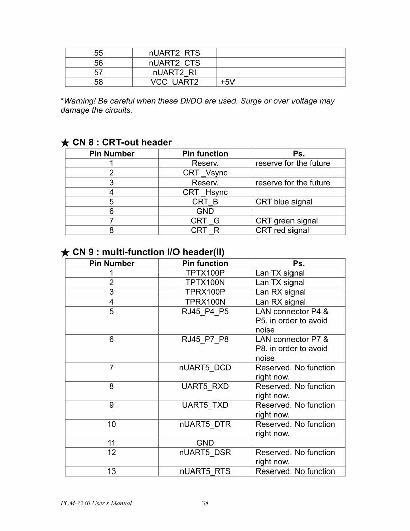
55 nUART2_RTS 56 nUART2_CTS 57 nUART2_RI 58 VCC_UART2 +5V
*Warning! Be careful when these DI/DO are used. Surge or over voltage may damage the circuits.
★ CN 8 : CRT-out header
Pin Number Pin function Ps. 1 Reserv. reserve for the future 2 CRT _Vsync 3 Reserv. reserve for the future 4 CRT _Hsync 5 CRT_B CRT blue signal 6 GND 7 CRT _G CRT green signal 8 CRT _R CRT red signal
★ CN 9 : multi-function I/O header(II)
Pin Number Pin function Ps. 1 TPTX100P Lan TX signal 2 TPTX100N Lan TX signal 3 TPRX100P Lan RX signal 4 TPRX100N Lan RX signal 5 RJ45_P4_P5 LAN connector P4 &
P5. in order to avoid noise
6 RJ45_P7_P8 LAN connector P7 & P8. in order to avoid noise
7 nUART5_DCD Reserved. No function right now.
8 UART5_RXD Reserved. No function right now.
9 UART5_TXD Reserved. No function right now.
10 nUART5_DTR Reserved. No function right now.
11 GND 12 nUART5_DSR Reserved. No function
right now. 13 nUART5_RTS Reserved. No function
PCM-7230 User’s Manual 38
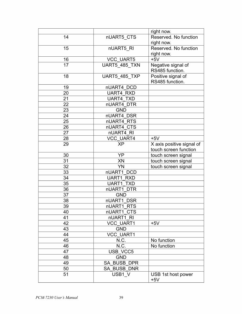
right now. 14 nUART5_CTS Reserved. No function
right now. 15 nUART5_RI Reserved. No function
right now. 16 VCC_UART5 +5V 17 UART5_485_TXN Negative signal of
RS485 function. 18 UART5_485_TXP Positive signal of
RS485 function. 19 nUART4_DCD 20 UART4_RXD 21 UART4_TXD 22 nUART4_DTR 23 GND 24 nUART4_DSR 25 nUART4_RTS 26 nUART4_CTS 27 nUART4_RI 28 VCC_UART4 +5V 29 XP X axis positive signal of
touch screen function 30 YP touch screen signal 31 XN touch screen signal 32 YN touch screen signal 33 nUART1_DCD 34 UART1_RXD 35 UART1_TXD 36 nUART1_DTR 37 GND 38 nUART1_DSR 39 nUART1_RTS 40 nUART1_CTS 41 nUART1_RI 42 VCC_UART1 +5V 43 GND 44 VCC_UART1 45 N.C. No function 46 N.C. No function 47 USB_VCC5 48 GND 49 SA_BUSB_DPR 50 SA_BUSB_DNR 51 USB1_V USB 1st host power
+5V
PCM-7230 User’s Manual 39
52 GND 53 USB1_P USB 1st host signal 54 USB1_N USB 1st host signal 55 USB2_V USB 2ed host power
+5V 56 GND 57 USB2_P USB 2ed host signal 58 USB2_N USB 2ed host signal
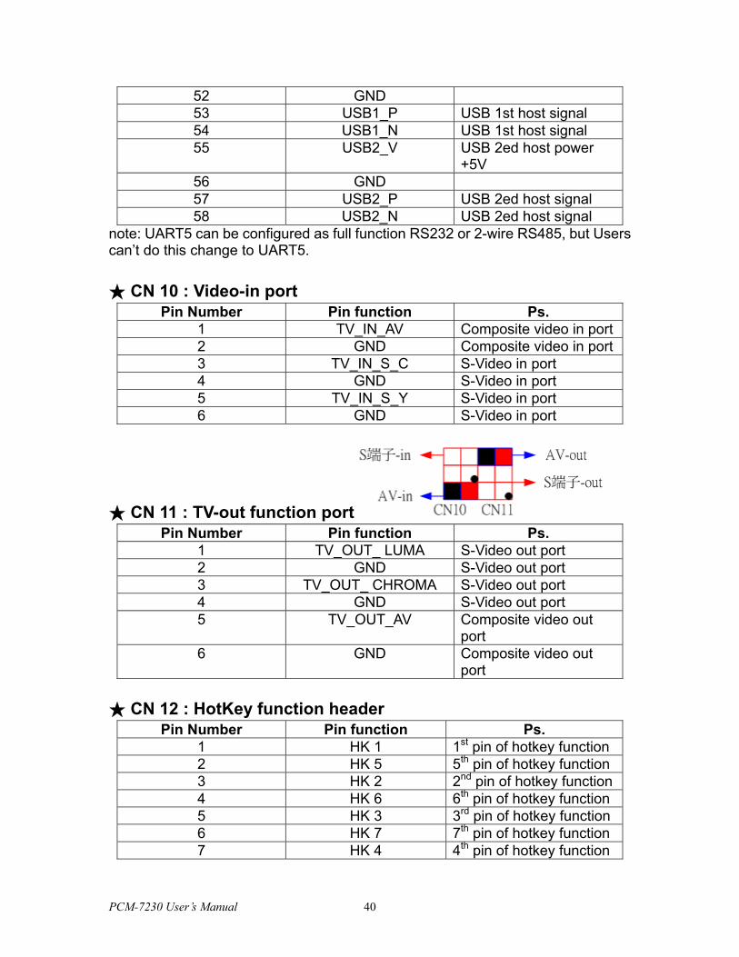
note: UART5 can be configured as full function RS232 or 2-wire RS485, but Users can’t do this change to UART5. ★ CN 10 : Video-in port
Pin Number Pin function Ps. 1 TV_IN_AV Composite video in port2 GND Composite video in port3 TV_IN_S_C S-Video in port 4 GND S-Video in port 5 TV_IN_S_Y S-Video in port 6 GND S-Video in port
★ CN 11 : TV-out function port Pin Number Pin function Ps.
1 TV_OUT_ LUMA S-Video out port 2 GND S-Video out port 3 TV_OUT_ CHROMA S-Video out port 4 GND S-Video out port 5 TV_OUT_AV Composite video out
port 6 GND Composite video out
port ★ CN 12 : HotKey function header
Pin Number Pin function Ps. 1 HK 1 1st pin of hotkey function 2 HK 5 5th pin of hotkey function 3 HK 2 2nd pin of hotkey function4 HK 6 6th pin of hotkey function 5 HK 3 3rd pin of hotkey function 6 HK 7 7th pin of hotkey function 7 HK 4 4th pin of hotkey function
PCM-7230 User’s Manual 40
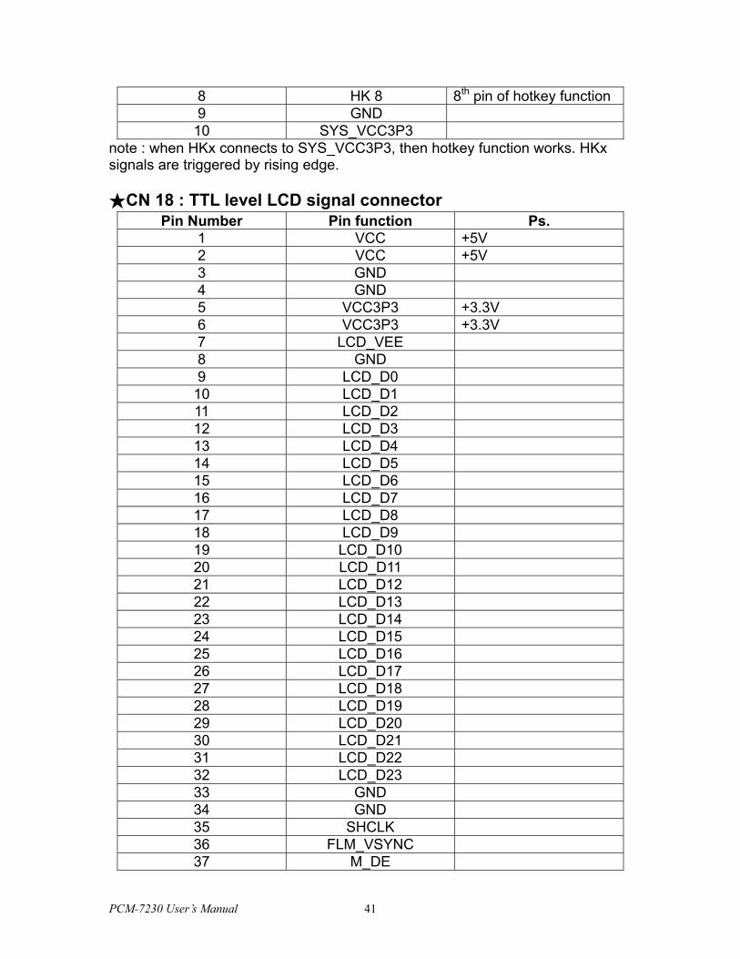
8 HK 8 8th pin of hotkey function 9 GND
10 SYS_VCC3P3 note : when HKx connects to SYS_VCC3P3, then hotkey function works. HKx signals are triggered by rising edge. ★CN 18 : TTL level LCD signal connector
Pin Number Pin function Ps. 1 VCC +5V 2 VCC +5V 3 GND 4 GND 5 VCC3P3 +3.3V 6 VCC3P3 +3.3V 7 LCD_VEE 8 GND 9 LCD_D0
10 LCD_D1 11 LCD_D2 12 LCD_D3 13 LCD_D4 14 LCD_D5 15 LCD_D6 16 LCD_D7 17 LCD_D8 18 LCD_D9 19 LCD_D10 20 LCD_D11 21 LCD_D12 22 LCD_D13 23 LCD_D14 24 LCD_D15 25 LCD_D16 26 LCD_D17 27 LCD_D18 28 LCD_D19 29 LCD_D20 30 LCD_D21 31 LCD_D22 32 LCD_D23 33 GND 34 GND 35 SHCLK 36 FLM_VSYNC 37 M_DE
PCM-7230 User’s Manual 41
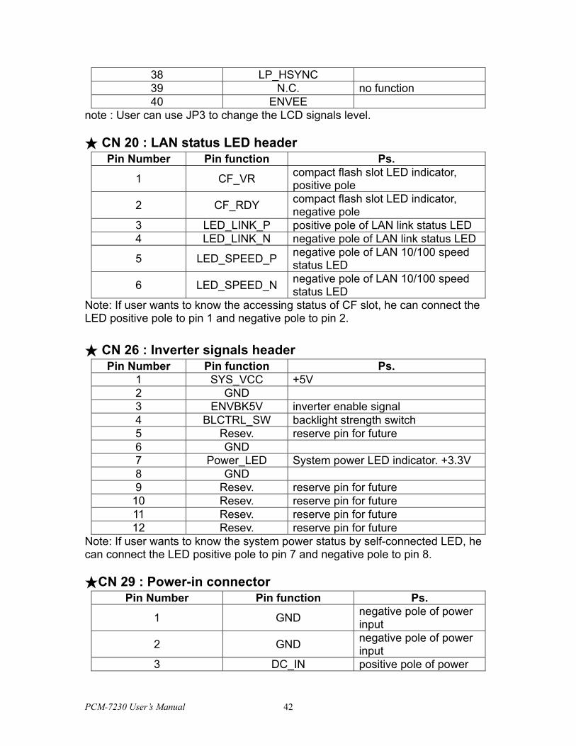
38 LP_HSYNC 39 N.C. no function 40 ENVEE
note : User can use JP3 to change the LCD signals level. ★ CN 20 : LAN status LED header
Pin Number Pin function Ps.
1 CF_VR compact flash slot LED indicator, positive pole
2 CF_RDY compact flash slot LED indicator, negative pole
3 LED_LINK_P positive pole of LAN link status LED 4 LED_LINK_N negative pole of LAN link status LED
5 LED_SPEED_P negative pole of LAN 10/100 speed status LED
6 LED_SPEED_N negative pole of LAN 10/100 speed status LED
Note: If user wants to know the accessing status of CF slot, he can connect the LED positive pole to pin 1 and negative pole to pin 2. ★ CN 26 : Inverter signals header
Pin Number Pin function Ps. 1 SYS_VCC +5V 2 GND 3 ENVBK5V inverter enable signal 4 BLCTRL_SW backlight strength switch 5 Resev. reserve pin for future 6 GND 7 Power_LED System power LED indicator. +3.3V 8 GND 9 Resev. reserve pin for future
10 Resev. reserve pin for future 11 Resev. reserve pin for future 12 Resev. reserve pin for future
Note: If user wants to know the system power status by self-connected LED, he can connect the LED positive pole to pin 7 and negative pole to pin 8. ★CN 29 : Power-in connector
Pin Number Pin function Ps.
1 GND negative pole of power input
2 GND negative pole of power input
3 DC_IN positive pole of power
PCM-7230 User’s Manual 42
input
4 DC_IN positive pole of power input
Note: CN29 is the main power input port. The DC_IN range is 8V ~ 28V. ★CN 31 : SM bus port
Pin Number Pin function Ps.
1 I2CSCL clock pin of SM bus for smart battery
2 GND
3 I2CSDA data pin of SM bus for smart battery
4 nDC_IN This pin is pulled low on PCM-7230 by 2M ohm.
3.1.4 COM1~COM5 serial ports
The PCM-7230 offers four full-functions RS-232 (COM1, COM2, COM3 and COM4) and one RS-485 w/ AFC (COM5) serial communication interface ports. Please refer to Appendix A for their pin assignments.
Automatic Data Flow Control Function for RS-485
The RS-485 in PCM-7230 will automatically sense the direction of incoming data and switch its transmission direction accordingly. Therefore no handshaking signal (e.g. RTS signal) is necessary. This feature lets users build an RS-485 network simply and quickly with just two wires. More importantly, application software previously written for half duplex RS-232 environments can be maintained without need for modification.
Optional Choice
All COM ports are configurable by Advantech. COM1~COM4 are selectable as full 9-pin TTL or transceiver Level RS232. COM5 port might be modified to one 2-wire TTL Level RS-232 serial communication interface ports (default is RS-485 w/ AFC) by Advantech according to customers’ need.
3.1.5 LAN: Ethernet Connector(CN9,Pin1~Pin6)
The PCM-7230 is equipped with one Davicom DM9000 10/100 Base-T Ethernet LAN controller. The second and third LED indicators (approach AMI-120 Interface) on board show the Link and Active (Green LED) status of this Ethernet port.
3.1.6 USB client connector(CN9,Pin47~Pin50)
PCM-7230 User’s Manual 43
This USB client connector is used to communicate with PC for ActiveSync. Users may connect the PCM-7230 with PC to develop their own applications and download files to PCM-7230.
3.1.7 DC power connector(CN29)
The DC power connector carries 12 VDC external power input and features reversed wiring protection. Therefore, it will not cause any damage to the system by reversed wiring of ground line and power line.
3.1.8 LCD display connector(TTL level:CN18 ; LVDS:J1)
This 40-pin LCD display connector is for LCD connectivity. The PCM-7230 supports both active and passive LCD displays, default is 18-bit 800*600 TFT color panel. The PCM-7230 provides a bias control signal which can be used to control the LCD bias voltage. It is recommended that the LCD bias voltage not be applied to the panel until the logic supply voltage (+5 V or +3.3 V) and panel video signals are stable. Under normal operation the control signal is active high. When the PCM-7230 board's power is applied, the control signal is low until just after the relevant flat panel signals are present. The PCM-7230 supports 5 V and 3.3 V LCD displays. By setting the JP3, users can select the panel video signal level to be 5V or 3.3V according to the LCD panel you used.
3.1.9 LCD inverter connector for 5V inverter(CN26, Pin1~Pin4)
Connect the PCM-7230 with the 5V inverter for adjusting LCD panel’s brightness. The voltage range of this signal is from 0 to 5V. When enable backlight is on, the voltage of this signal is 5V; otherwise is 0V. Brightness voltage is adjustable by Advantech SW utility.
3.1.10 Audio connector(CN3,P25~P36)
The PCM-7230 provides audio signals on pin25 ~ pin36 of CN3. These audio signals include Microphone in (mono), Line in/out (stereo) and two speaker-out function.
3.1.11 Battery and DC power status monitor connector(CN31)
With this connector, the PCM-7230 can monitor and report the battery and DC power status thru I2C bus.
3.1.12 4-wire touch-screen connector(CN9,Pin29~Pin32)
Connect the PCM-7230 with the 4-wire touch-screen. The PCM-7230 supports
PCM-7230 User’s Manual 44
4-wire resistive touch-screen. Figure 3.7 shows the cable connected to this connector.
3.1.13 8 DI,8 DO pin header (CN3,Pin7~Pin24) & HotKey pin header(CN12)
This connector connects the PCM-7230 with the 8 DI & 8 DO. The PCM-7230 has 8-channel digital inputs,8-channel digital outputs and 8 HotKey pins. HotKey function is configurable by Advantech System configurator.
3.1.14 AMI-120 connector (CN32)
The PCM-7230 provides a unique and unified interface, AMI-120-120 (ARM Module Interface) interface, to expand its functionality. The 120-pin AMI-120-120 interface uses PC-104 connector, a 15mm high profile Board-to-Board connector, with different pins definition. Users can use Advantech’s standard AMI-120 solution modules or develop your own AMI-120 module for functionality expansion in an easy, flexible, low cost and fast way. The AMI-120 interface is also opened to customized solution modules. For detail information about pin assignment, please refer to Appendix B.
3.1.16 PCMCIA slot (U10)
The PCM-7230 default provides one type II hot-swappable PCMCIA slots in the solder side for CompactFlash card, wireless LAN card, etc.
3.1.17 100-pin board-to-board connector for Memory Module (CN14)
The PCM-7230 can flexible expand its memory size thru this 100-pin B2B connector. It default equips one Memory Module with 32MB Flash (without SDRAM). Users can optional select the Memory Module with 16/32 MB Flash and/or 32/64 MB SDRAM according to their application’s size.
Another issue related to the Memory Module is boot priority. Users may put your image files into flash on the Memory Module by Advantech upgrade utility. Users may also put your image files in the CompactFlash card as another choices and boot from PCMCIA or CF slots. In this case user can select not to use Memory Module or use a Memory Module with 64MB SDRAM, totally 128MB SDRAM supported by the PCM-7230 series. The CompactFlash card always comes the first priority when system is booting.
PCM-7230 User’s Manual 45
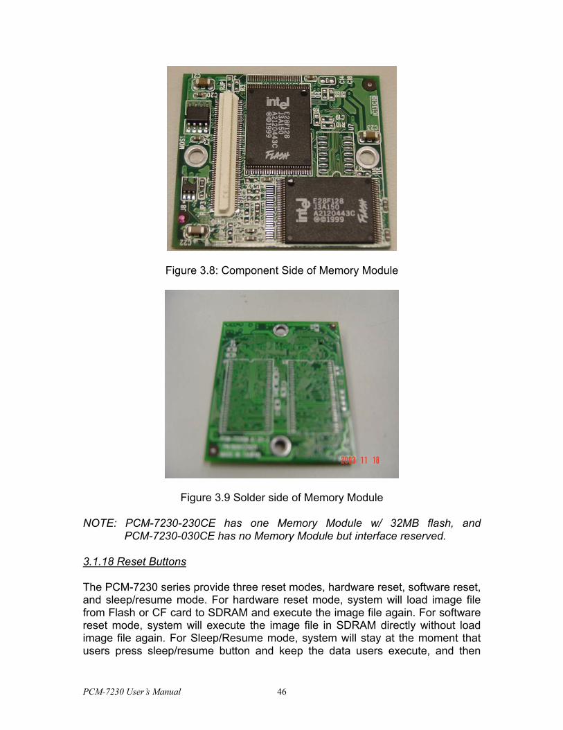
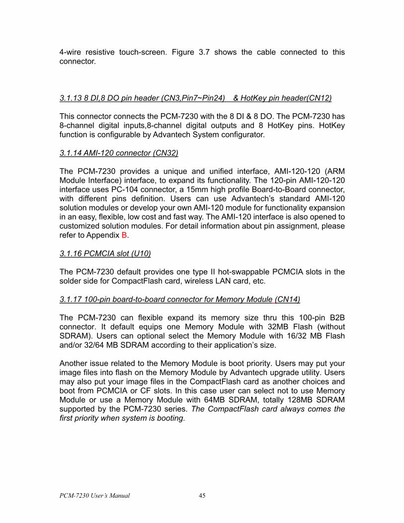
Figure 3.8: Component Side of Memory Module
Figure 3.9 Solder side of Memory Module
NOTE: PCM-7230-230CE has one Memory Module w/ 32MB flash, and PCM-7230-030CE has no Memory Module but interface reserved.
3.1.18 Reset Buttons
The PCM-7230 series provide three reset modes, hardware reset, software reset, and sleep/resume mode. For hardware reset mode, system will load image file from Flash or CF card to SDRAM and execute the image file again. For software reset mode, system will execute the image file in SDRAM directly without load image file again. For Sleep/Resume mode, system will stay at the moment that users press sleep/resume button and keep the data users execute, and then
PCM-7230 User’s Manual 46
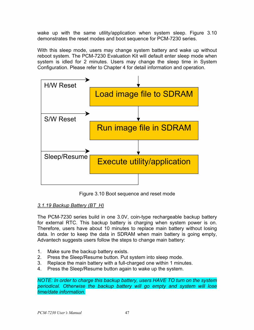
wake up with the same utility/application when system sleep. Figure 3.10 demonstrates the reset modes and boot sequence for PCM-7230 series.
With this sleep mode, users may change system battery and wake up without reboot system. The PCM-7230 Evaluation Kit will default enter sleep mode when system is idled for 2 minutes. Users may change the sleep time in System Configuration. Please refer to Chapter 4 for detail information and operation.
Load image file to SDRAM
Run image file in SDRAM
Execute utility/application
H/W Reset
S/W Reset
Sleep/Resume
Figure 3.10 Boot sequence and reset mode
3.1.19 Backup Battery (BT_H)
The PCM-7230 series build in one 3.0V, coin-type rechargeable backup battery for external RTC. This backup battery is charging when system power is on. Therefore, users have about 10 minutes to replace main battery without losing data. In order to keep the data in SDRAM when main battery is going empty, Advantech suggests users follow the steps to change main battery:
1. Make sure the backup battery exists. 2. Press the Sleep/Resume button. Put system into sleep mode. 3. Replace the main battery with a full-charged one within 1 minutes. 4. Press the Sleep/Resume button again to wake up the system.
NOTE: In order to charge this backup battery, users HAVE TO turn on the system periodical. Otherwise the backup battery will go empty and system will lose time/date information.
PCM-7230 User’s Manual 47
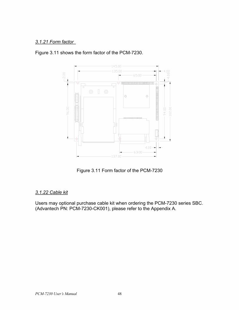
3.1.21 Form factor
Figure 3.11 shows the form factor of the PCM-7230.
Figure 3.11 Form factor of the PCM-7230
3.1.22 Cable kit
Users may optional purchase cable kit when ordering the PCM-7230 series SBC. (Advantech PN: PCM-7230-CK001), please refer to the Appendix A.
PCM-7230 User’s Manual 48
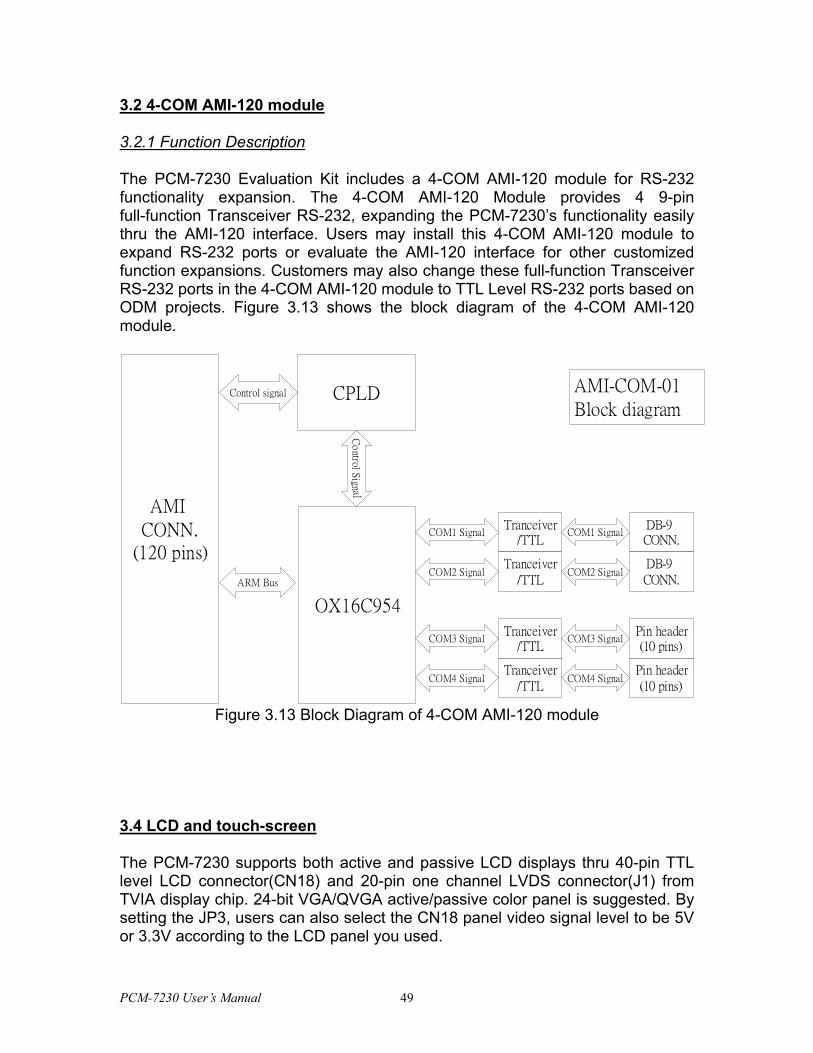
3.2 4-COM AMI-120 module
3.2.1 Function Description
The PCM-7230 Evaluation Kit includes a 4-COM AMI-120 module for RS-232 functionality expansion. The 4-COM AMI-120 Module provides 4 9-pin full-function Transceiver RS-232, expanding the PCM-7230’s functionality easily thru the AMI-120 interface. Users may install this 4-COM AMI-120 module to expand RS-232 ports or evaluate the AMI-120 interface for other customized function expansions. Customers may also change these full-function Transceiver RS-232 ports in the 4-COM AMI-120 module to TTL Level RS-232 ports based on ODM projects. Figure 3.13 shows the block diagram of the 4-COM AMI-120 module.
AMI CONN.
(120 pins)
ARM Bus
CPLD
OX16C954
Control signal
Co
ntrol Sign al
COM1 Signal
Tranceiver/TTL
AMI-COM-01 Block diagram
Tranceiver/TTL
Tranceiver/TTL
Tranceiver/TTL
COM2 Signal
COM3 Signal
COM4 Signal
DB-9 CONN.
DB-9 CONN.
Pin header(10 pins)
Pin header(10 pins)
COM1 Signal
COM2 Signal
COM3 Signal
COM4 Signal
Figure 3.13 Block Diagram of 4-COM AMI-120 module
3.4 LCD and touch-screen
The PCM-7230 supports both active and passive LCD displays thru 40-pin TTL level LCD connector(CN18) and 20-pin one channel LVDS connector(J1) from TVIA display chip. 24-bit VGA/QVGA active/passive color panel is suggested. By setting the JP3, users can also select the CN18 panel video signal level to be 5V or 3.3V according to the LCD panel you used.
PCM-7230 User’s Manual 49

The LCD panel in the PCM-7230 Evaluation Kit is a 10.4’’, 800(H) X 600(V), 18-bit one channel LVDS SVGA TFT panel (Unipac UB104S01). With the 5V inverter, the PCM-7230 Evaluation Kit is able to adjust LCD’s brightness by Advantech’s software utility. The voltage range of this signal is from 0 to 5V. When enable backlight is on, the voltage of this signal is 5V; otherwise is 0V. Users may refer to Chapter 4 for detail information. The touch screen in the PCM-7230 Evaluation Kit is a 4-wire touch screen. The PCM-7230 supports only 4-wire touch-screen.
Nevertheless, the specifications of various LCD diversify substantially. The newest supporting list will be included in a progressive technical reference by Advantech. Please contact with local Advantech representatives or surf the website of Advantech: http://support.advantech.com.
3.5 Power system
The power system of the PCM-7230 Evaluation Kit includes charger board, 4S1P, 2000mAH Li-ion battery, adapter and power cord.
Users can only use a 2.5φ19Vdc power adapter to be the PCM-7230 Evaluation Kit’s power input. The 4S1P, 2000mAH, rechargeable Li-Ion battery pack can also provide the PCM-7230 power input through the charger board. Thru the smart battery interface (SM Bus), users can get the battery information such as battery capacity, charging status and so on by Advantech’s software utility. When the battery capacity is not full, the charger board will automatically charge the battery pack if the 19Vdc power adapter plugged, no matter the power switch turns on or off.
There is one 3.0V, coin-type rechargeable backup battery on the PCM-7230 SBCs. This coin battery is mainly for external RTC of the PCM-7230. When the power switch is on, the external DC power will automatically charge this coin battery. When system is closed or in sleep mode, this backup battery will provide power for RTC to keep time/date information. However, users should periodically turn on the power switch and plug the adapter in order to charge both the coin battery and Li-Ion battery. Otherwise you will lose all time/date information. The coin battery can also help users to replace empty Li-Ion battery. Please refer to 3.1.20 for detail steps.
PCM-7230 User’s Manual 50
CHAPTER
4 Software Functionality This chapter details the Windows®
CE.NET operating system on the
PCM-7230 series products.
Sections include:
• Introduction
• Windows® CE.NET utility on the
PCM-7230 Evaluation Kit
• PCM-7230 Networking Utilities
• Intel® Persistent Storage Manger (IPSM)
• Application Program Development
• Windows® CE.NET Components
PCM-7230 User’s Manual 51
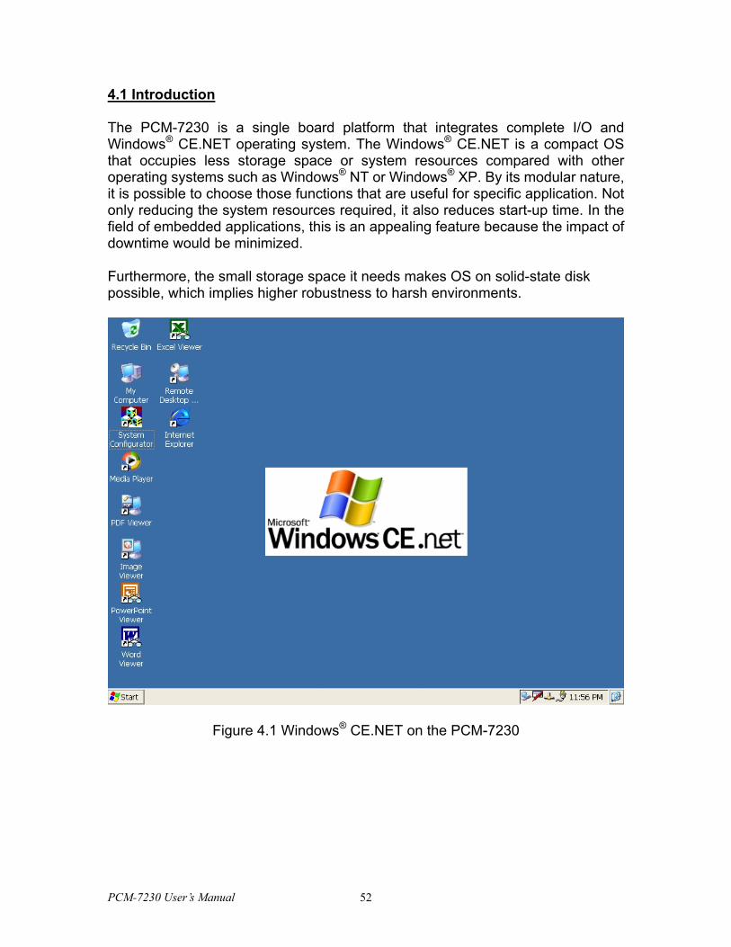
4.1 Introduction
The PCM-7230 is a single board platform that integrates complete I/O and Windows® CE.NET operating system. The Windows® CE.NET is a compact OS that occupies less storage space or system resources compared with other operating systems such as Windows® NT or Windows® XP. By its modular nature, it is possible to choose those functions that are useful for specific application. Not only reducing the system resources required, it also reduces start-up time. In the field of embedded applications, this is an appealing feature because the impact of downtime would be minimized.
Furthermore, the small storage space it needs makes OS on solid-state disk possible, which implies higher robustness to harsh environments.
Figure 4.1 Windows® CE.NET on the PCM-7230
PCM-7230 User’s Manual 52
4.2 PCM-7230 Utilities
There are several useful utilities added in the standard Windows® CE.NET OS of the PCM-7230:
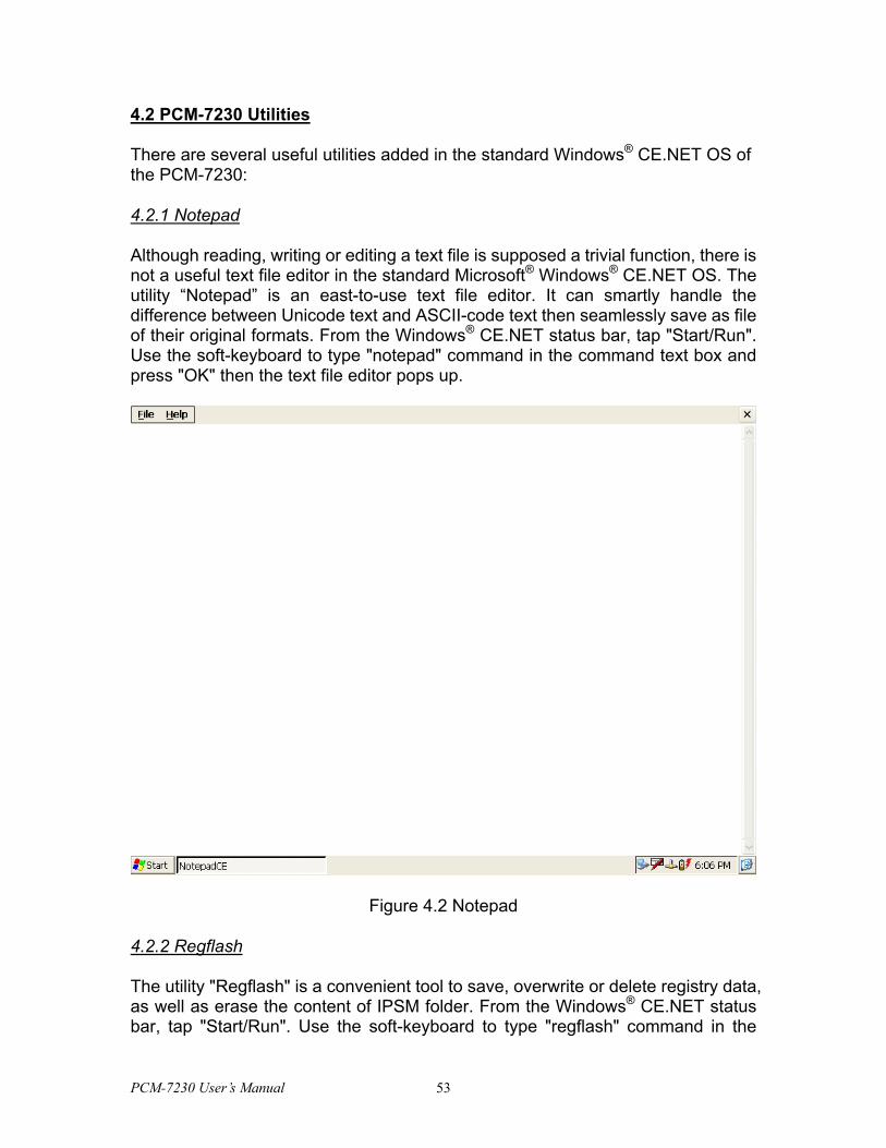
4.2.1 Notepad
Although reading, writing or editing a text file is supposed a trivial function, there is not a useful text file editor in the standard Microsoft® Windows® CE.NET OS. The utility “Notepad” is an east-to-use text file editor. It can smartly handle the difference between Unicode text and ASCII-code text then seamlessly save as file of their original formats. From the Windows® CE.NET status bar, tap "Start/Run". Use the soft-keyboard to type "notepad" command in the command text box and press "OK" then the text file editor pops up.
Figure 4.2 Notepad
4.2.2 Regflash
The utility "Regflash" is a convenient tool to save, overwrite or delete registry data, as well as erase the content of IPSM folder. From the Windows® CE.NET status bar, tap "Start/Run". Use the soft-keyboard to type "regflash" command in the
PCM-7230 User’s Manual 53
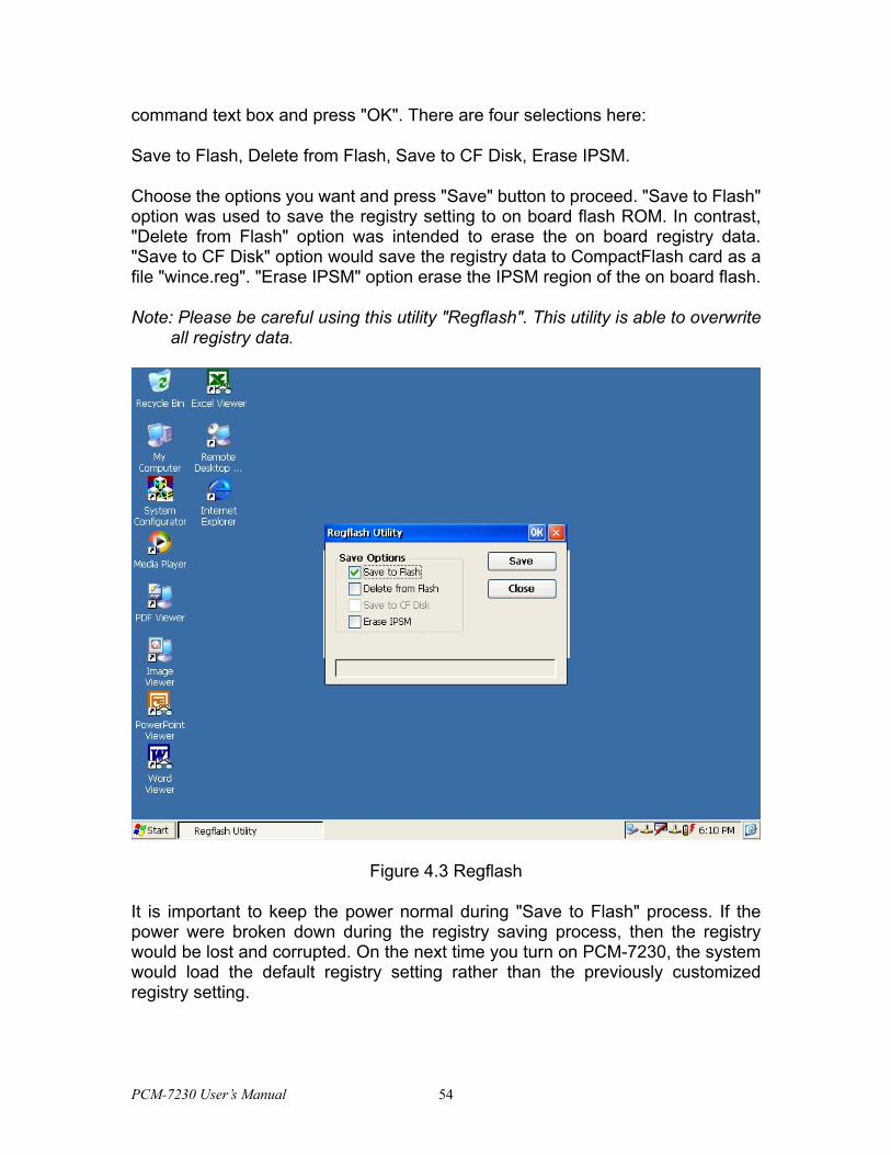
command text box and press "OK". There are four selections here:
Save to Flash, Delete from Flash, Save to CF Disk, Erase IPSM.
Choose the options you want and press "Save" button to proceed. "Save to Flash" option was used to save the registry setting to on board flash ROM. In contrast, "Delete from Flash" option was intended to erase the on board registry data. "Save to CF Disk" option would save the registry data to CompactFlash card as a file "wince.reg". "Erase IPSM" option erase the IPSM region of the on board flash.
Note: Please be careful using this utility "Regflash". This utility is able to overwrite all registry data.
Figure 4.3 Regflash
It is important to keep the power normal during "Save to Flash" process. If the power were broken down during the registry saving process, then the registry would be lost and corrupted. On the next time you turn on PCM-7230, the system would load the default registry setting rather than the previously customized registry setting.
PCM-7230 User’s Manual 54
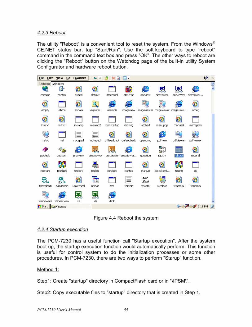
4.2.3 Reboot
The utility "Reboot" is a convenient tool to reset the system. From the Windows® CE.NET status bar, tap "Start/Run". Use the soft-keyboard to type "reboot" command in the command text box and press "OK". The other ways to reboot are clicking the “Reboot” button on the Watchdog page of the built-in utility System Configurator and hardware reboot button.
Figure 4.4 Reboot the system
4.2.4 Startup execution
The PCM-7230 has a useful function call "Startup execution". After the system boot up, the startup execution function would automatically perform. This function is useful for control system to do the initialization processes or some other procedures. In PCM-7230, there are two ways to perform "Starup" function.
Method 1:
Step1: Create "startup" directory in CompactFlash card or in "\IPSM\".
Step2: Copy executable files to "startup" directory that is created in Step 1.
PCM-7230 User’s Manual 55
Example:
We copy two executable files "REGFLASH.exe" and "Notepad.exe" in "\IPSM\Startup", and then reboot the system. After the system boot up, the two executable file would automatically execute.
Method 2:
Step1: The same as Step1 in Method 1.
Step2: Create a file called "startup.ini" in "startup" directory. Type in the commands you want to execute after boot up in that file.
Example:
Create "Startup.ini" in "\IPSM\Startup" directory and reboot the system. The content of startup.ini was listed below:
\windows\tty.exe
\windows\registry.exe
After the system reboot, "\windows\ tty.exe" and "\windows\ registry.exe" would automatically execute. Be sure that the two methods are independent. It means they can be used simultaneously.
4.2.5 Safemode
PCM-7230 utilities allow user to alter registry setting, and save it by either "regflash.exe" or the registry frame of the “Misc” page of the System Configurator. But sometimes user may make some non-appropriate registry setting, and cause PCM-7230 fail to boot. In the circumstance, the easiest way to boot up PCM-7230 is to use the default registry setting from the Windows® CE.NET image. When the PCM-7230 is booted up with the default registry setting, we say that it is working in "safemode". To enter "safemode", user must perform several steps as described below:
Step 1: Create a file whose filename is "safemode" or a directory whose name is "safemode" in the CompactFlash card.
Step 2: Insert the CompactFlash card into the PCM-7230.
Step 3: Turn on the power switch of PCM-7230.
4.2.6 System Configurator
PCM-7230 User’s Manual 56
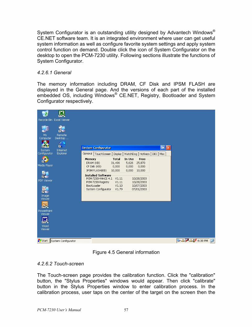
System Configurator is an outstanding utility designed by Advantech Windows® CE.NET software team. It is an integrated environment where user can get useful system information as well as configure favorite system settings and apply system control function on demand. Double click the icon of System Configurator on the desktop to open the PCM-7230 utility. Following sections illustrate the functions of System Configurator.
4.2.6.1 General
The memory information including DRAM, CF Disk and IPSM FLASH are displayed in the General page. And the versions of each part of the installed embedded OS, including Windows® CE.NET, Registry, Bootloader and System Configurator respectively.
Figure 4.5 General information
4.2.6.2 Touch-screen
The Touch-screen page provides the calibration function. Click the "calibration" button, the "Stylus Properties" windows would appear. Then click "calibrate" button in the Stylus Properties window to enter calibration process. In the calibration process, user taps on the center of the target on the screen then the
PCM-7230 User’s Manual 57
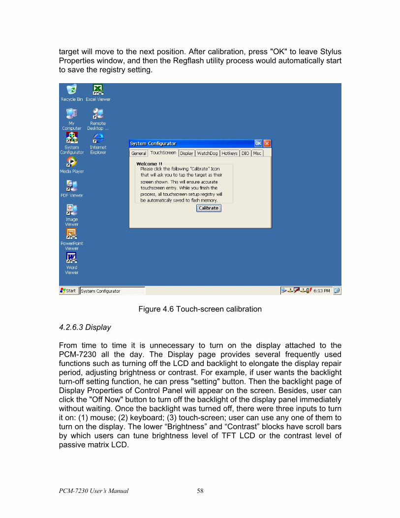
target will move to the next position. After calibration, press "OK" to leave Stylus Properties window, and then the Regflash utility process would automatically start to save the registry setting.
Figure 4.6 Touch-screen calibration
4.2.6.3 Display
From time to time it is unnecessary to turn on the display attached to the PCM-7230 all the day. The Display page provides several frequently used functions such as turning off the LCD and backlight to elongate the display repair period, adjusting brightness or contrast. For example, if user wants the backlight turn-off setting function, he can press "setting" button. Then the backlight page of Display Properties of Control Panel will appear on the screen. Besides, user can click the "Off Now" button to turn off the backlight of the display panel immediately without waiting. Once the backlight was turned off, there were three inputs to turn it on: (1) mouse; (2) keyboard; (3) touch-screen; user can use any one of them to turn on the display. The lower “Brightness” and “Contrast” blocks have scroll bars by which users can tune brightness level of TFT LCD or the contrast level of passive matrix LCD.
PCM-7230 User’s Manual 58
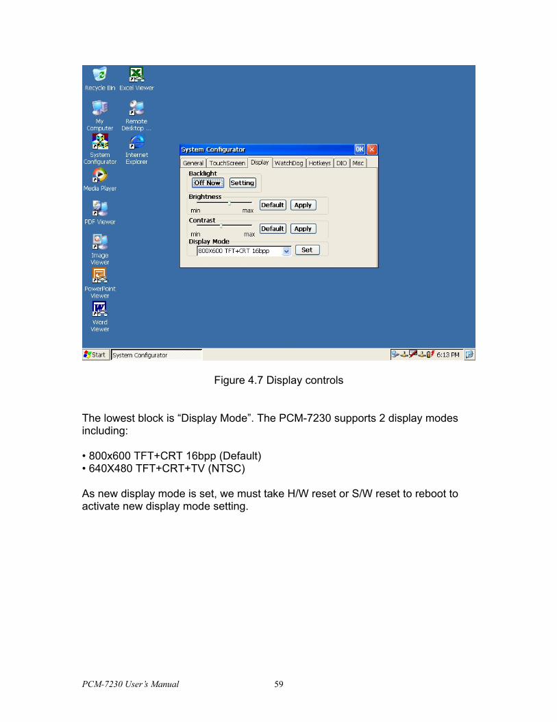
Figure 4.7 Display controls
The lowest block is “Display Mode”. The PCM-7230 supports 2 display modes including: • 800x600 TFT+CRT 16bpp (Default) • 640X480 TFT+CRT+TV (NTSC) As new display mode is set, we must take H/W reset or S/W reset to reboot to activate new display mode setting.
PCM-7230 User’s Manual 59
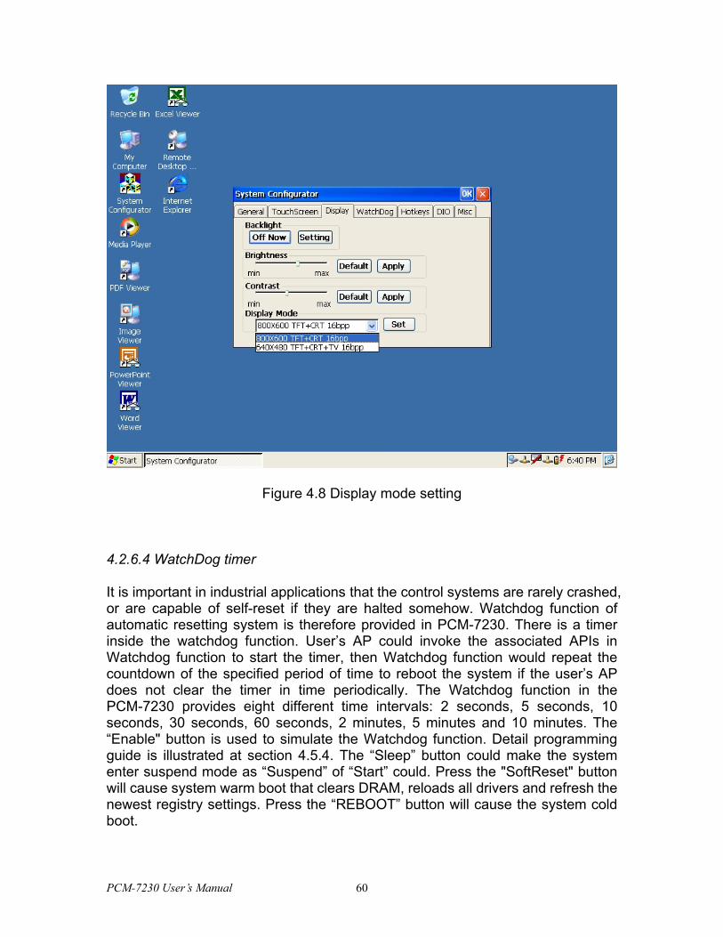
Figure 4.8 Display mode setting
4.2.6.4 WatchDog timer
It is important in industrial applications that the control systems are rarely crashed, or are capable of self-reset if they are halted somehow. Watchdog function of automatic resetting system is therefore provided in PCM-7230. There is a timer inside the watchdog function. User’s AP could invoke the associated APIs in Watchdog function to start the timer, then Watchdog function would repeat the countdown of the specified period of time to reboot the system if the user’s AP does not clear the timer in time periodically. The Watchdog function in the PCM-7230 provides eight different time intervals: 2 seconds, 5 seconds, 10 seconds, 30 seconds, 60 seconds, 2 minutes, 5 minutes and 10 minutes. The “Enable" button is used to simulate the Watchdog function. Detail programming guide is illustrated at section 4.5.4. The “Sleep” button could make the system enter suspend mode as “Suspend” of “Start” could. Press the "SoftReset" button will cause system warm boot that clears DRAM, reloads all drivers and refresh the newest registry settings. Press the “REBOOT” button will cause the system cold boot.
PCM-7230 User’s Manual 60
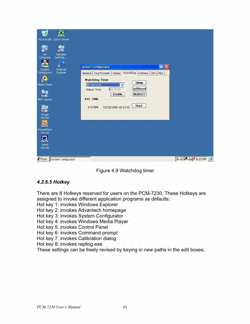
Figure 4.9 Watchdog timer
4.2.6.5 Hotkey There are 8 Hotkeys reserved for users on the PCM-7230. These Hotkeys are assigned to invoke different application programs as defaults: Hot key 1: invokes Windows Explorer Hot key 2: invokes Advantech homepage Hot key 3: invokes System Configurator Hot key 4: invokes Windows Media Player Hot key 5: invokes Control Panel Hot key 6: invokes Command prompt Hot key 7: invokes Calibration dialog Hot key 8: invokes repllog.exe These settings can be freely revised by keying in new paths in the edit boxes.
PCM-7230 User’s Manual 61
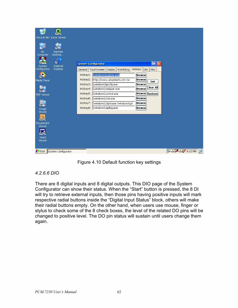
Figure 4.10 Default function key settings
4.2.6.6 DIO
There are 8 digital inputs and 8 digital outputs. This DIO page of the System Configurator can show their status. When the “Start” button is pressed, the 8 DI will try to retrieve external inputs, then those pins having positive inputs will mark respective radial buttons inside the “Digital Input Status” block, others will make their radial buttons empty. On the other hand, when users use mouse, finger or stylus to check some of the 8 check boxes, the level of the related DO pins will be changed to positive level. The DO pin status will sustain until users change them again.
PCM-7230 User’s Manual 62
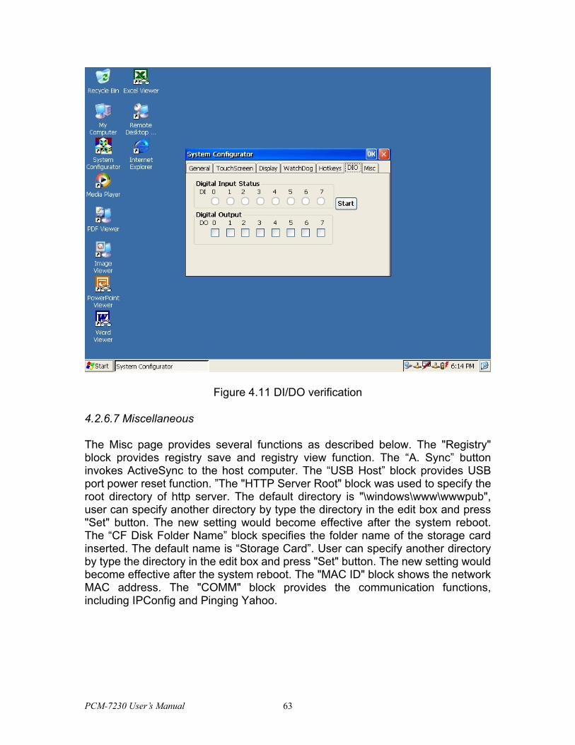
Figure 4.11 DI/DO verification
4.2.6.7 Miscellaneous
The Misc page provides several functions as described below. The "Registry" block provides registry save and registry view function. The “A. Sync” button invokes ActiveSync to the host computer. The “USB Host” block provides USB port power reset function. ”The "HTTP Server Root" block was used to specify the root directory of http server. The default directory is "\windows\www\wwwpub", user can specify another directory by type the directory in the edit box and press "Set" button. The new setting would become effective after the system reboot. The “CF Disk Folder Name” block specifies the folder name of the storage card inserted. The default name is “Storage Card”. User can specify another directory by type the directory in the edit box and press "Set" button. The new setting would become effective after the system reboot. The "MAC ID" block shows the network MAC address. The "COMM" block provides the communication functions, including IPConfig and Pinging Yahoo.
PCM-7230 User’s Manual 63
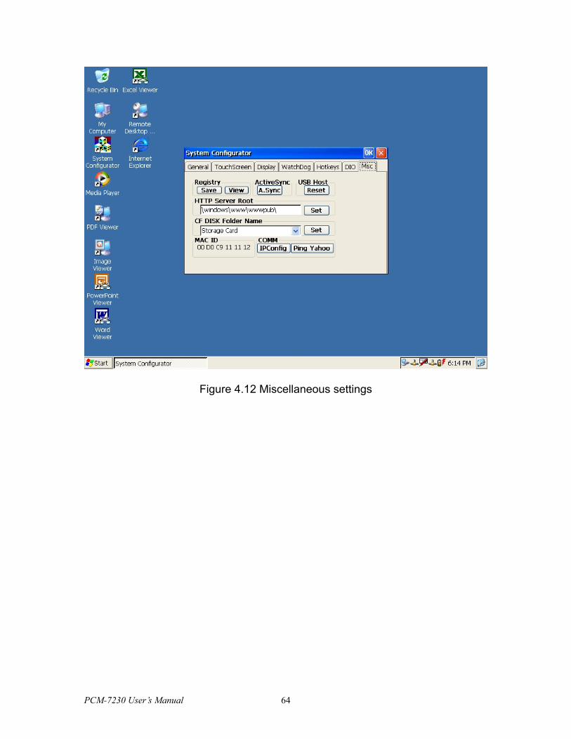
Figure 4.12 Miscellaneous settings
PCM-7230 User’s Manual 64
4.3 PCM-7230 Networking
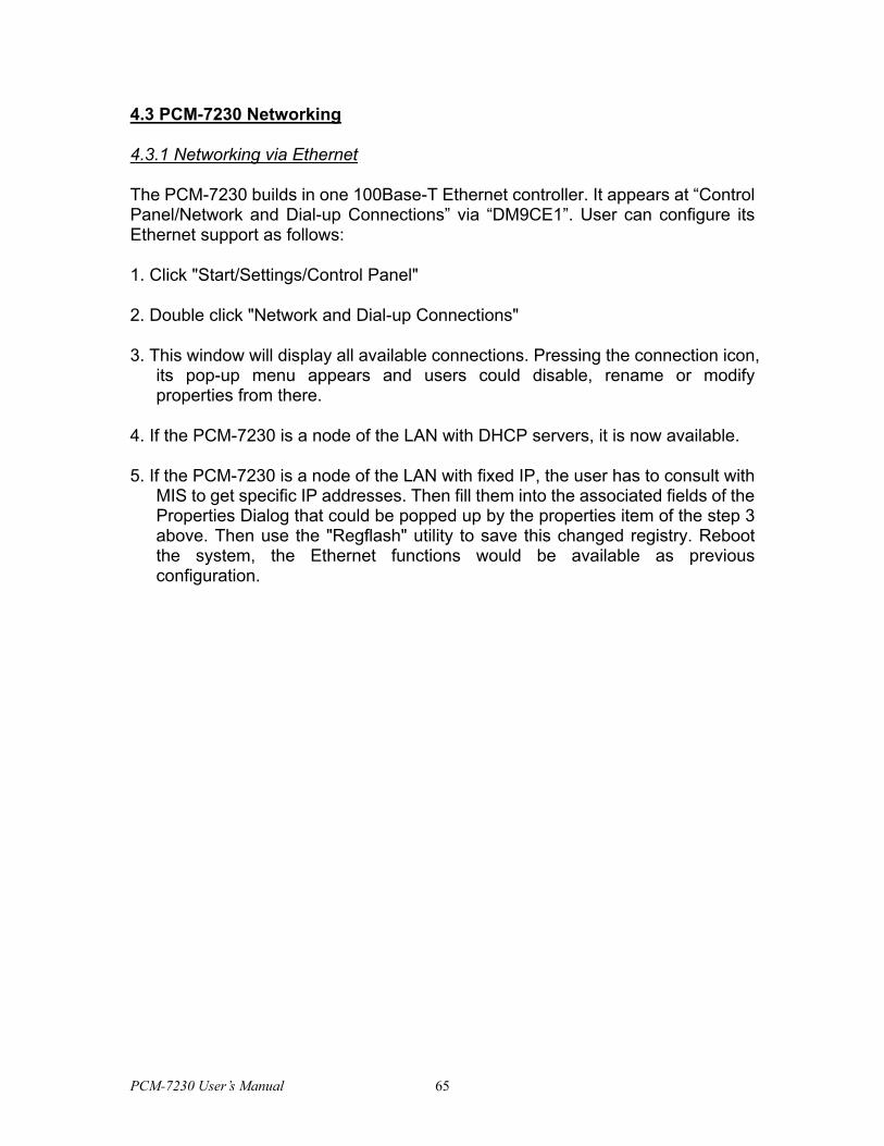
4.3.1 Networking via Ethernet
The PCM-7230 builds in one 100Base-T Ethernet controller. It appears at “Control Panel/Network and Dial-up Connections” via “DM9CE1”. User can configure its Ethernet support as follows:
1. Click "Start/Settings/Control Panel"
2. Double click "Network and Dial-up Connections"
3. This window will display all available connections. Pressing the connection icon, its pop-up menu appears and users could disable, rename or modify properties from there.
4. If the PCM-7230 is a node of the LAN with DHCP servers, it is now available.
5. If the PCM-7230 is a node of the LAN with fixed IP, the user has to consult with MIS to get specific IP addresses. Then fill them into the associated fields of the Properties Dialog that could be popped up by the properties item of the step 3 above. Then use the "Regflash" utility to save this changed registry. Reboot the system, the Ethernet functions would be available as previous configuration.
PCM-7230 User’s Manual 65
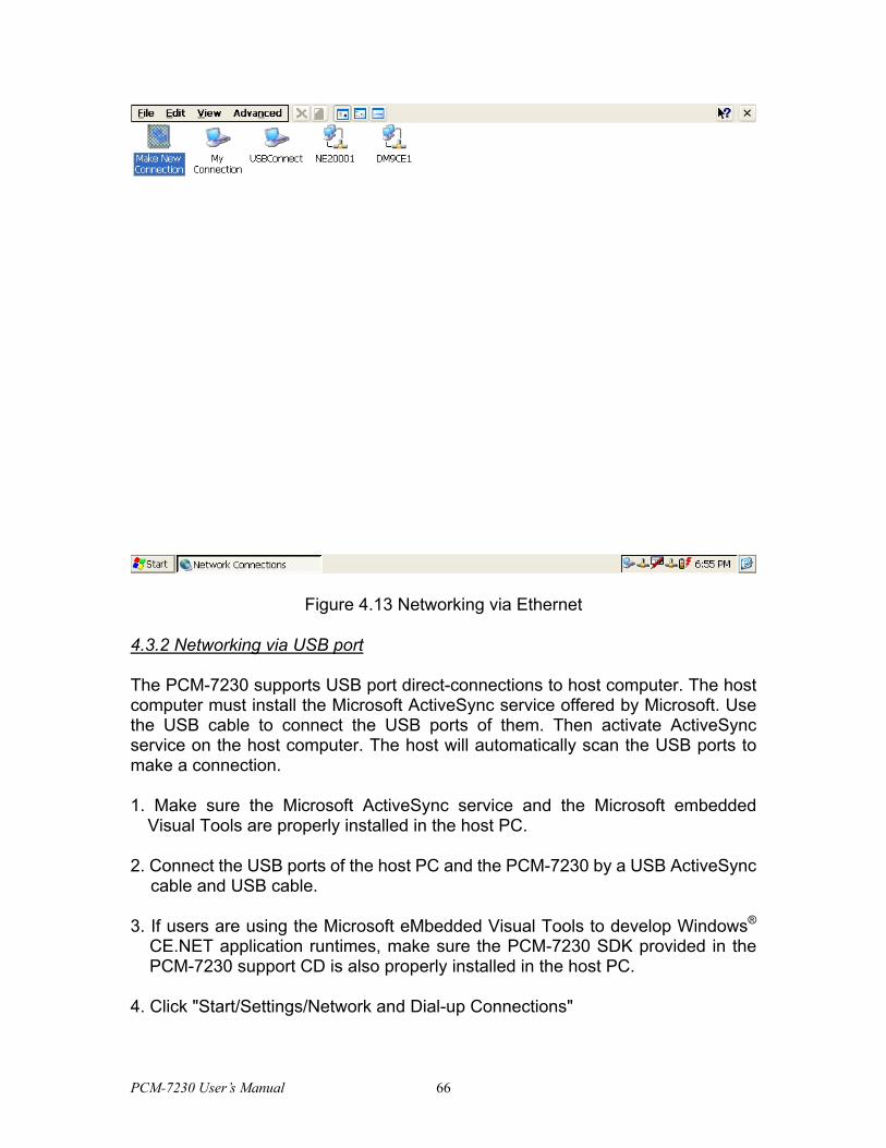
Figure 4.13 Networking via Ethernet
4.3.2 Networking via USB port
The PCM-7230 supports USB port direct-connections to host computer. The host computer must install the Microsoft ActiveSync service offered by Microsoft. Use the USB cable to connect the USB ports of them. Then activate ActiveSync service on the host computer. The host will automatically scan the USB ports to make a connection.
1. Make sure the Microsoft ActiveSync service and the Microsoft embedded Visual Tools are properly installed in the host PC.
2. Connect the USB ports of the host PC and the PCM-7230 by a USB ActiveSync cable and USB cable.
3. If users are using the Microsoft eMbedded Visual Tools to develop Windows® CE.NET application runtimes, make sure the PCM-7230 SDK provided in the PCM-7230 support CD is also properly installed in the host PC.
4. Click "Start/Settings/Network and Dial-up Connections"
PCM-7230 User’s Manual 66

5. Make a new connection. As the dialogue box pops out, choose the default "Direct Connection" radial button. Click "Next".
6. Select "USB Cable" from the combo box and click "Finish" to complete making new connection. It is recommended to keep the default settings of the ports connection.
7. Click “PC Connection” icon in the Control Panel. As the “PC Connection Properties” dialogue box pops up, change the connection to the newly made connection by clicking the “Change...” button.
8. If the ActiveSync service on the host PC has been activated, the above seven steps will make the PCM-7230 automatically try to connect the host, ;otherwise you can invoke "\windows\reglog.exe" to do the activesync connection.
NOTE: Users should properly install the associated USB driver on the host computer while plugging in the PCM-7230 as a USB client device at the first time.
NOTE: The USB driver--wceusbsh.inf and wceusbsh.sys--are included in PCM-7230 support CD.
NOTE: Users may also use COM ports to do ActiveSync function thru RS-232 cable but may not be fully supported.
PCM-7230 User’s Manual 67
Figure 4.14 Networking via USB port
4.3.3 Networking via PPP
The PCM-7230 supports PPP protocol. To setup and utilize it, follow the steps below:
1. Click "Start/Settings/Network and Dial-up Connections”
2. Make a new connection. As the dialogue box pops out, choose the "Dial-Up Connection". Click "Next".
3. Click "Configure" to setup the device according to the specification of your modem, and then click "OK" on the top-right corner of the window.
4. Click "Next". Input the telephone number in the "Phone Number" window. Press "Finish" to complete the setup process.
5. Turn on your modem and use RS-232 cable to connect modem and COM1 of PCM-7230.
6. Double click the connection you have made in Step 4. Key in the user name,
PCM-7230 User’s Manual 68
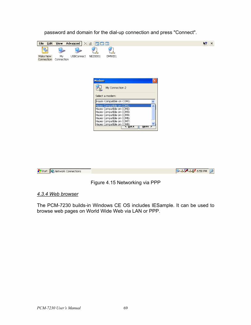
password and domain for the dial-up connection and press "Connect".
Figure 4.15 Networking via PPP
4.3.4 Web browser
The PCM-7230 builds-in Windows CE OS includes IESample. It can be used to browse web pages on World Wide Web via LAN or PPP.
PCM-7230 User’s Manual 69

4.4 Intel Persistent Storage Manger (IPSM)
4.4.1 Introduction to Intel Persistent Storage Manger
Intel Persistent Storage Manager was designed and developed specifically as an enhancement to Microsoft Windows CE operating systems. IPSM eliminates extra disk-like storage such as storage cards, redundant RAM and ROM.
4.4.2 IPSM in PCM-7230
PCM-7230 uses Intel Persistent Storage Manger to utilize the free space of flash rom for persistent storage. The IPSM region in the system is located in "\IPSM" directory. Any file or directory stored in "\IPSM" directory would be keep persistently, even if the power of PCM-7230 were turned off. The user can store software or data in \IPSM rather in CompactFlash card to avoid inconvenience.
PCM-7230 User’s Manual 70
4.5 Application Program Development
The PCM-7230 is bundled with built-in Windows® CE.NET operating system. In real applications users need to execute various application programs on it. However, unlike its other family, the Windows® CE.NET is a hardware-dependent operating system. That is to say, Windows® CE.NET application programs are only portable in the source code level. Users must rebuild the runtime file for a different Windows® CE.NET platform even though the source code may not be changed at all.
4.5.1 System requirements
• Intel® Pentium-90 CPU or more advanced
• Microsoft® Windows® 2000 Professional or Windows® XP
• Microsoft® eMbedded Visual Tools 4.0
• Platform SDK for PCM-7230 (bundled in the standard PCM-7230)
• 64MB DRAM
• CD-ROM drive
• Monitor with VGA resolution at least
• Mouse
• 200MB free hard disk space at least
• PCM-7230
• Let the host PC and PCM-7230 connect on the same LAN to do kernel debugging if necessary
• USB cable (bundled in the standard PCM-7230)
4.5.2 Building Windows CE runtime
By the platform SDK bundled with the standard PCM-7230, users can build the Windows CE runtime by the eMbedded Visual Tools.
PCM-7230 User’s Manual 71
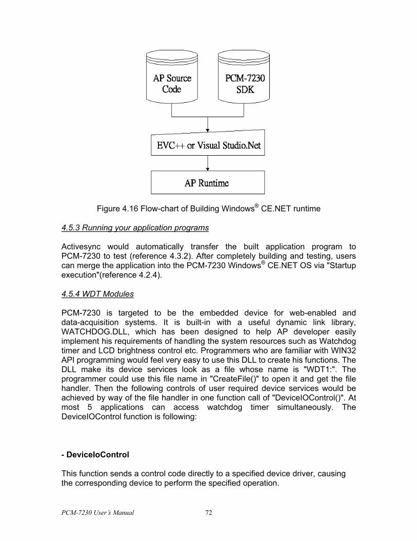
Figure 4.16 Flow-chart of Building Windows® CE.NET runtime
4.5.3 Running your application programs
Activesync would automatically transfer the built application program to PCM-7230 to test (reference 4.3.2). After completely building and testing, users can merge the application into the PCM-7230 Windows® CE.NET OS via "Startup execution"(reference 4.2.4).
4.5.4 WDT Modules
PCM-7230 is targeted to be the embedded device for web-enabled and data-acquisition systems. It is built-in with a useful dynamic link library, WATCHDOG.DLL, which has been designed to help AP developer easily implement his requirements of handling the system resources such as Watchdog timer and LCD brightness control etc. Programmers who are familiar with WIN32 API programming would feel very easy to use this DLL to create his functions. The DLL make its device services look as a file whose name is "WDT1:". The programmer could use this file name in "CreateFile()" to open it and get the file handler. Then the following controls of user required device services would be achieved by way of the file handler in one function call of "DeviceIOControl()". At most 5 applications can access watchdog timer simultaneously. The DeviceIOControl function is following:
- DeviceIoControl
This function sends a control code directly to a specified device driver, causing the corresponding device to perform the specified operation.
PCM-7230 User’s Manual 72
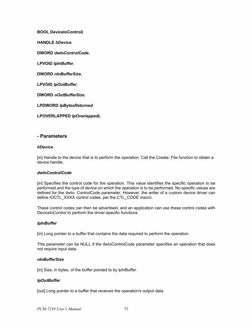
BOOL DeviceIoControl(
HANDLE hDevice,
DWORD dwIoControlCode,
LPVOID lpInBuffer,
DWORD nInBufferSize,
LPVOID lpOutBuffer,
DWORD nOutBufferSize,
LPDWORD lpBytesReturned,
LPOVERLAPPED lpOverlapped);
- Parameters
hDevice
[in] Handle to the device that is to perform the operation. Call the Create- File function to obtain a device handle.
dwIoControlCode
[in] Specifies the control code for the operation. This value identifies the specific operation to be performed and the type of device on which the operation is to be performed. No specific values are defined for the dwIo- ControlCode parameter. However, the writer of a custom device driver can define IOCTL_XXXX control codes, per the CTL_CODE macro.
These control codes can then be advertised, and an application can use these control codes with DeviceIoControl to perform the driver-specific functions.
lpInBuffer
[in] Long pointer to a buffer that contains the data required to perform the operation.
This parameter can be NULL if the dwIoControlCode parameter specifies an operation that does not require input data.
nInBufferSize
[in] Size, in bytes, of the buffer pointed to by lpInBuffer.
lpOutBuffer
[out] Long pointer to a buffer that receives the operation's output data.
PCM-7230 User’s Manual 73
This parameter can be NULL if the dwIoControlCode parameter specifies an operation that does not produce output data.
nOutBufferSize
[in] Size, in bytes, of the buffer pointed to by lpOutBuffer.
lpBytesReturned
[out] Long pointer to a variable that receives the size, in bytes, of the data stored into the buffer pointed to by lpOutBuffer.
The lpBytesReturned parameter cannot be NULL. Even when an operation produces no output data, and lpOutBuffer can be NULL, the Device-IoControl function makes use of the variable pointed to by lpBytesReturned. After such an operation, the value of the variable is without meaning.
lpOverlapped
[in] Ignored; set to NULL.
- Return Values
Nonzero indicates success. Zero indicates failure. To get extended error information, call GetLastError.
WDT Control Codes
There are 8 control codes for the operation codes in the WDT1 driver:
1. IOCTL_ENABLE_WDT (0x1001):
Enables the Watchdog timer on your application. Your application must trigger to Watchdog timer by IOCTL_ACCESS_WDT interface during specified period, otherwise the device will reboot automatically
lpInBuffer : unsed.
nInBufferSize: unused.
lpOutBuffer: unused.
nOutBufferSize: unused.
PCM-7230 User’s Manual 74

2. IOCTL_DISABLE_WDT (0x1002):
Disable the Watchdog time on your application.
lpInBuffer : unsed.
nInBufferSize: unused.
lpOutBuffer: unused.
nOutBufferSize: unused.
3. IOCTL_GET_WDTPERIOD (0x1003):
lpInBuffer :unused.
nInBufferSize: unused.
lpOutBuffer: the DWORD pointer to your Watchdog time setting. The unit is mini-second. Its value should be greater 1000. The default setting is 5000 mini-seconds.
nOutBufferSize: unused.
4. IOCTL_SET_WDTPERIOD (0x1004):
lpInBuffer : the DWORD pointer to your Watchdog time setting. Its value should be greater 1000. The unit is mini-second. If your application opens the WDT driver, the default Watchdog timer is set to 5000 mini-seconds.
nInBufferSize:.unused.
lpOutBuffer: unused.
nOutBufferSize: unused.
5. IOCTL_ACCESS_WDT (0x1005):
Your application must trigger the Watchdog once during your Watchdog timer period. If your application has not trigger at the specified period, the device will reboot automatically.
lpInBuffer :unused.
nInBufferSize:.unused.
lpOutBuffer: unused.
PCM-7230 User’s Manual 75
nOutBufferSize: unused.
6. IOCTL_GET_SCREENOFFTIME (0x1006):
lpInBuffer :unused.
nInBufferSize: unused.
lpOutBuffer: the DWORD pointer to your screen off time if user-interface idled. The unit is mini-second. If the value is 0, screen-off function is disabled.
nOutBufferSize: unused.
7. IOCTL_SET_SCREENOFFTIME (0x1007):
lpInBuffer : the DWORD pointer to your screen off time if user-interface idled. The unit is mini-second. If the value is 0, screen-off function is disabled.
nInBufferSize:unused.
lpOutBuffer: unused.
nOutBufferSize: unused.
8. IOCTL_SET_SCREENOFF (0x1010):
Set the LCD power off immediately.
lpInBuffer : unused.
nInBufferSize:.unused.
lpOutBuffer: unused.
nOutBufferSize: unused.
Examples:
#define IOCTL_ENABLE_WDT 0x1001
#define IOCTL_DISABLE_WDT 0x1002
#define IOCTL_GET_WDTPERIOD 0x1003
PCM-7230 User’s Manual 76
#define IOCTL_SET_WDTPERIOD 0x1004
#define IOCTL_ACCESS_WDT 0x1005
#define IOCTL_GET_SCREENOFFTIME 0x1006
#define IOCTL_SET_SCREENOFFTIME 0x1007
#define IOCTL_SET_SCREENON 0x100F
#define IOCTL_SET_SCREENOFF 0x1010
HANDLE m_hWDT=NULL;
TCHAR szClassName[60];
...
// assign the WDT driver name
wsprintf(szClassName, TEXT("WDT1:"));
// Open the WDT driver
m_hWDT = CreateFile(szClassName, GENERIC_READ | GENERIC_WRITE, 0,
NULL, OPEN_EXISTING, FILE_ATTRIBUTE_NORMAL, NULL);
if ( m_hWDT == INVALID_HANDLE_VALUE )
{
DebugMsg(CString("WDT driver fail"));
return;
}
...
DWORD dwTemp;
DWORD nPeriod=10000;
// Set the Watchdog Timer as 10 seconds (10000 mini-seconds)
DeviceIoControl(m_hWDT, IOCTL_SET_WDTPERIOD, &nPeriod, 4, NULL, 0, &dwTemp, NULL);
// Enable the Watchdog timer
DeviceIoControl(m_hWDT, IOCTL_ENABLE_WDT, NULL, NULL, NULL, 0, &dwTemp, NULL);
PCM-7230 User’s Manual 77
While (1)
{
// do your job here...
Sleep(8000);
DeviceIoControl(m_hWDT, IOCTL_ACCESS_WDT, NULL, NULL, NULL, 0, &dwTemp, NULL);
}
DeviceIoControl(m_hWDT, IOCTL_DISABLE_WDT, NULL, NULL, NULL, 0, NULL, NULL);
CloseHandle(m_hWDT);
4.5.5 DIO Modules
PCM-7230 has 8 DI(Digital Input), 8 DO(Digital Output). Users can access these resources by writing windows programs with WIN32 API. PCM-7230 is built-in the DIO driver to allow users accessing DI and DO values. Users should use WIN32 APIs to access them. The driver name is "DIO1:". The programmers must open this driver before using the resources. Then programmers could use DeviceIOControl functions to access DO and DI values. The function description of DeviceIOControl is illustrated in section 4.5.4. There are 3 control codes for the operation codes in the DIO driver:
1. IOCTL_GET_DI (0x1002):
lpInBuffer : the pointer to the DI index. Its range is from 0 to 7.
nInBufferSize: unused.
lpOutBuffer: the pointer to the current DI value. Its value should be 0 or 1.
nOutBufferSize: unused.
2. IOCTL_GET_DO (0x1003):
lpInBuffer : the pointer to the DO index. Its range is from 0 to 7.
nInBufferSize: unused.
lpOutBuffer: the pointer to the current DI value. Its value should be 0 or 1.
PCM-7230 User’s Manual 78
nOutBufferSize: unused.
3. IOCTL_SET_DO (0x1005):
lpInBuffer : the pointer to the DO index. Its range is from 0 to 7.
nInBufferSize: the setting value. It must be 0 or 1.
lpOutBuffer: unused.
nOutBufferSize: unused.
Examples:
#define IOCTL_GET_DI 0x1002
#define IOCTL_GET_DO 0x1003
#define IOCTL_SET_DO 0x1005
HANDLE g_hDIO=NULL;
TCHAR szClassName[60];
...
// assign the DIO driver name
wsprintf(szClassName, TEXT("DIO1:"));
// Open the DIO driver
g_hDIO = CreateFile(szClassName, GENERIC_READ | GENERIC_WRITE, 0, NULL,
OPEN_EXISTING, FILE_ATTRIBUTE_NORMAL, NULL);
if ( g_hDIO == INVALID_HANDLE_VALUE )
{
DebugMsg(CString("DIO driver fail"));
return;
}
PCM-7230 User’s Manual 79

...
// Get the DO 2 value into nV
DWORD dwTemp;
DWORD nDO = 2;
int nV;
DeviceIoControl(g_hDIO, IOCTL_GET_DO, (LPVOID)&nDO, 4, (LPVOID)&nV, 4, &dwTemp, NULL);
CloseHandle(g_hDIO);
PCM-7230 User’s Manual 80
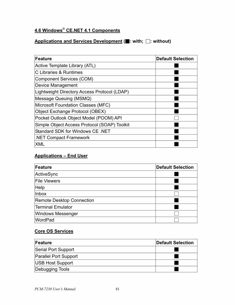
4.6 Windows® CE.NET 4.1 Components
Applications and Services Development (■: with; □: without)
Feature Default Selection Active Template Library (ATL) ■ C Libraries & Runtimes ■ Component Services (COM) ■ Device Management ■ Lightweight Directory Access Protocol (LDAP) ■ Message Queuing (MSMQ) ■ Microsoft Foundation Classes (MFC) ■ Object Exchange Protocol (OBEX) ■ Pocket Outlook Object Model (POOM) API □ Simple Object Access Protocol (SOAP) Toolkit ■ Standard SDK for Windows CE .NET ■ .NET Compact Framework ■ XML ■ Applications – End User Feature Default Selection ActiveSync ■ File Viewers ■ Help ■ Inbox □ Remote Desktop Connection ■ Terminal Emulator ■ Windows Messenger □ WordPad □ Core OS Services Feature Default Selection Serial Port Support ■ Parallel Port Support ■ USB Host Support ■ Debugging Tools ■
PCM-7230 User’s Manual 81
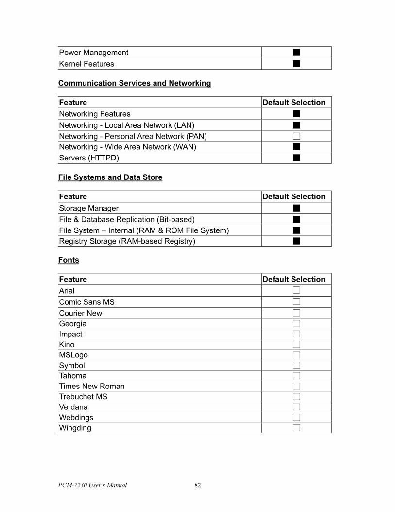
Power Management ■ Kernel Features ■ Communication Services and Networking Feature Default Selection Networking Features ■ Networking - Local Area Network (LAN) ■ Networking - Personal Area Network (PAN) □ Networking - Wide Area Network (WAN) ■ Servers (HTTPD) ■ File Systems and Data Store Feature Default Selection Storage Manager ■ File & Database Replication (Bit-based) ■ File System – Internal (RAM & ROM File System) ■ Registry Storage (RAM-based Registry) ■ Fonts Feature Default Selection Arial □ Comic Sans MS □ Courier New □ Georgia □ Impact □ Kino □ MSLogo □ Symbol □ Tahoma □ Times New Roman □ Trebuchet MS □ Verdana □ Webdings □ Wingding □
PCM-7230 User’s Manual 82
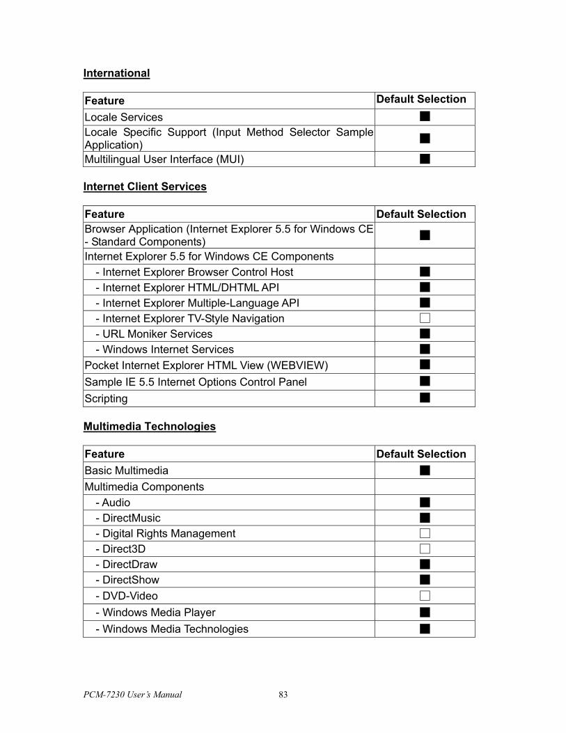
International Feature Default Selection Locale Services ■ Locale Specific Support (Input Method Selector Sample Application) ■
Multilingual User Interface (MUI) ■ Internet Client Services Feature Default Selection Browser Application (Internet Explorer 5.5 for Windows CE - Standard Components) ■
Internet Explorer 5.5 for Windows CE Components - Internet Explorer Browser Control Host ■ - Internet Explorer HTML/DHTML API ■ - Internet Explorer Multiple-Language API ■ - Internet Explorer TV-Style Navigation □ - URL Moniker Services ■ - Windows Internet Services ■
Pocket Internet Explorer HTML View (WEBVIEW) ■ Sample IE 5.5 Internet Options Control Panel ■ Scripting ■ Multimedia Technologies Feature Default Selection Basic Multimedia ■ Multimedia Components
- Audio ■ - DirectMusic ■ - Digital Rights Management □ - Direct3D □ - DirectDraw ■ - DirectShow ■ - DVD-Video □ - Windows Media Player ■ - Windows Media Technologies ■
PCM-7230 User’s Manual 83
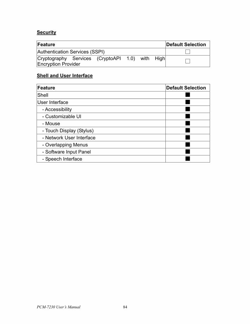
Security Feature Default Selection Authentication Services (SSPI) □ Cryptography Services (CryptoAPI 1.0) with High Encryption Provider □
Shell and User Interface Feature Default Selection Shell ■ User Interface ■
- Accessibility ■ - Customizable UI ■ - Mouse ■ - Touch Display (Stylus) ■ - Network User Interface ■ - Overlapping Menus ■ - Software Input Panel ■ - Speech Interface ■
PCM-7230 User’s Manual 84
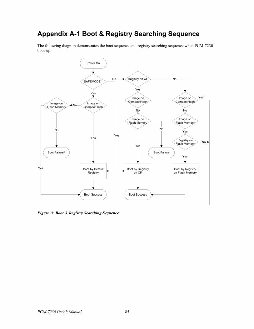
Appendix A-1 Boot & Registry Searching Sequence The following diagram demonstrates the boot sequence and registry searching sequence when PCM-7230 boot-up.
Power On
SAFEMODE*1
Image onCompactFlash
Registry on CF
Image onFlash Memory
Boot Failure*2
Boot by DefaultRegistry
Boot Success
Image onCompactFlash
Image onFlash Memory
Boot by Registryon CF
Image onCompactFlash
Image onFlash Memory
Registry onFlash Memory
Boot by Registryon Flash Memory
Yes
No
Yes
No
No
Yes
Yes
No
No
No
Yes
Yes
Boot Success
Yes
Yes
No
Yes
Boot Failure
No
Figure A: Boot & Registry Searching Sequence
PCM-7230 User’s Manual 85
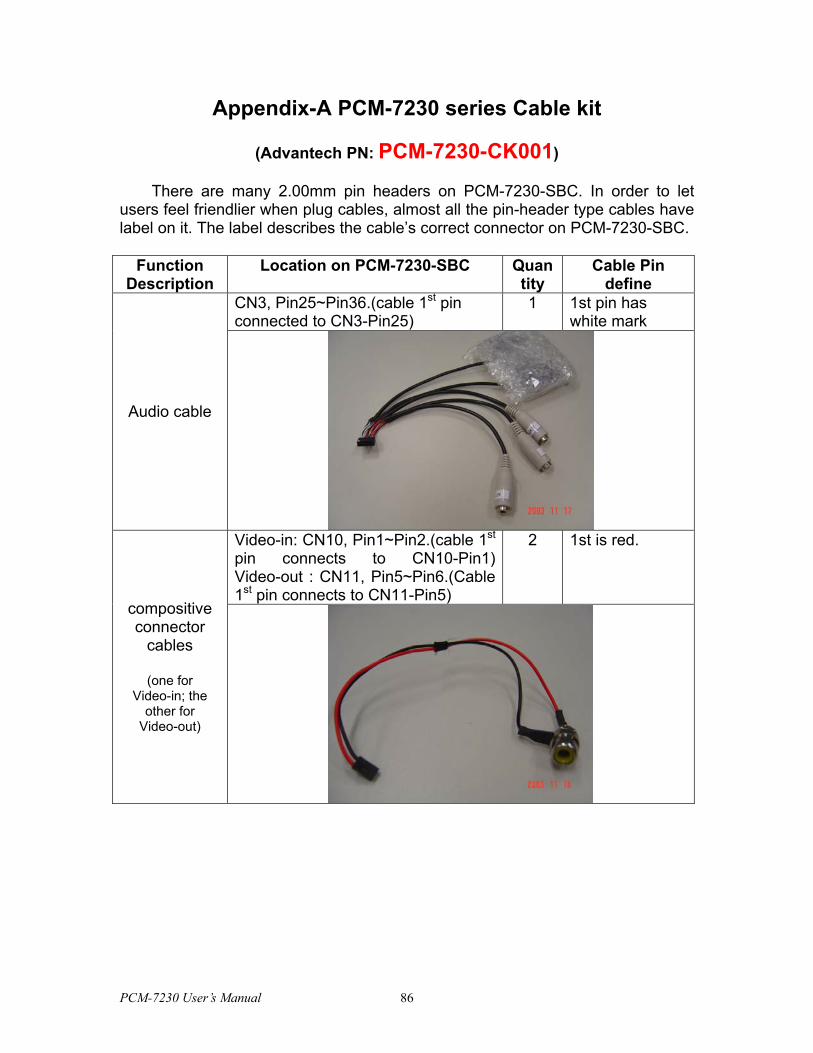
Appendix-A PCM-7230 series Cable kit
(Advantech PN: PCM-7230-CK001)
There are many 2.00mm pin headers on PCM-7230-SBC. In order to let users feel friendlier when plug cables, almost all the pin-header type cables have label on it. The label describes the cable’s correct connector on PCM-7230-SBC.
Function Description
Location on PCM-7230-SBC Quantity
Cable Pin define
CN3, Pin25~Pin36.(cable 1st pin connected to CN3-Pin25)
1 1st pin has white mark
Audio cable
Video-in: CN10, Pin1~Pin2.(cable 1st pin connects to CN10-Pin1) Video-out : CN11, Pin5~Pin6.(Cable 1st pin connects to CN11-Pin5)
2 1st is red.
compositive connector
cables
(one for Video-in; the
other for Video-out)
PCM-7230 User’s Manual 86
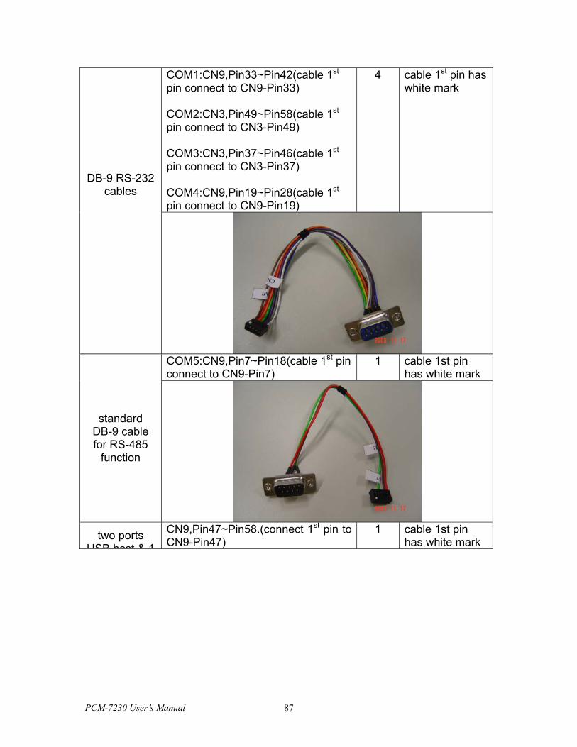
COM1:CN9,Pin33~Pin42(cable 1st pin connect to CN9-Pin33)
COM3:CN3,Pin37~Pin46(cable 1st pin connect to CN3-Pin37)
COM4:CN9,Pin19~Pin28(cable 1st pin connect to CN9-Pin19)
4 cable 1st pin has white mark
DB-9 RS-232 cables
COM5:CN9,Pin7~Pin18(cable 1st pin connect to CN9-Pin7)
1 cable 1st pin has white mark
standard DB-9 cable for RS-485
function
two ports
USB host & 1
CN9,Pin47~Pin58.(connect 1st pin to CN9-Pin47)
1 cable 1st pin has white mark
COM2:CN3,Pin49~Pin58(cable 1st pin connect to CN3-Pin49)
PCM-7230 User’s Manual 87
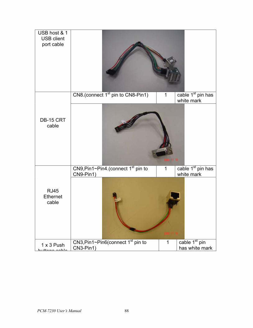
USB host & 1 USB client port cable
CN8.(connect 1st pin to CN8-Pin1) 1 cable 1st pin has
white mark
DB-15 CRT cable
CN9,Pin1~Pin4.(connect 1st pin to CN9-Pin1)
1 cable 1st pin has white mark
RJ45 Ethernet
cable
1 x 3 Push
buttons cable
CN3,Pin1~Pin6(connect 1st pin to CN3-Pin1)
1 cable 1st pin has white mark
PCM-7230 User’s Manual 88
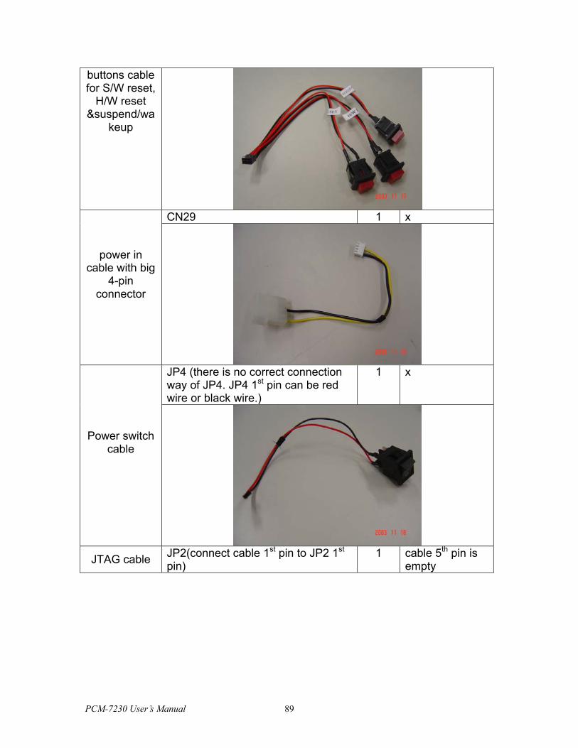
buttons cable for S/W reset,
H/W reset &suspend/wa
keup
CN29 1 x
power in cable with big
4-pin connector
JP4 (there is no correct connection way of JP4. JP4 1st pin can be red wire or black wire.)
1 x
Power switch cable
JTAG cable JP2(connect cable 1st pin to JP2 1st
pin) 1 cable 5th pin is
empty
PCM-7230 User’s Manual 89
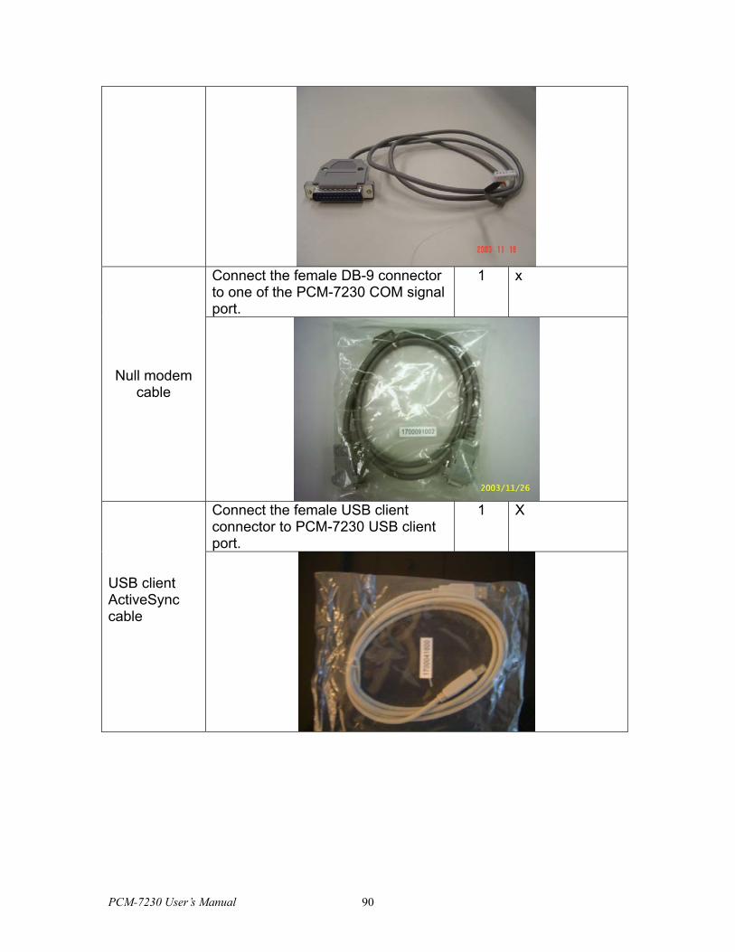
Connect the female DB-9 connector to one of the PCM-7230 COM signal port.
1 x
Null modem cable
Connect the female USB client connector to PCM-7230 USB client port.
1 X
USB client ActiveSync cable
PCM-7230 User’s Manual 90
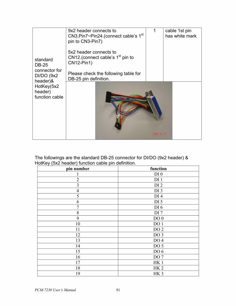
9x2 header connects to CN3,Pin7~Pin24.(connect cable’s 1st pin to CN3-Pin7)
5x2 header connects to CN12.(connect cable’s 1st pin to CN12-Pin1)
Please check the following table for DB-25 pin definition.
1 cable 1st pin has white mark
standard DB-25 connector for DI/DO (9x2 header)& HotKey(5x2 header) function cable
The followings are the standard DB-25 connector for DI/DO (9x2 header) & HotKey (5x2 header) function cable pin definition.
pin number function 1 DI 0 2 DI 1 3 DI 2 4 DI 3 5 DI 4 6 DI 5 7 DI 6 8 DI 7 9 DO 0 10 DO 1 11 DO 2 12 DO 3 13 DO 4 14 DO 5 15 DO 6 16 DO 7 17 HK 1 18 HK 2 19 HK 3
PCM-7230 User’s Manual 91
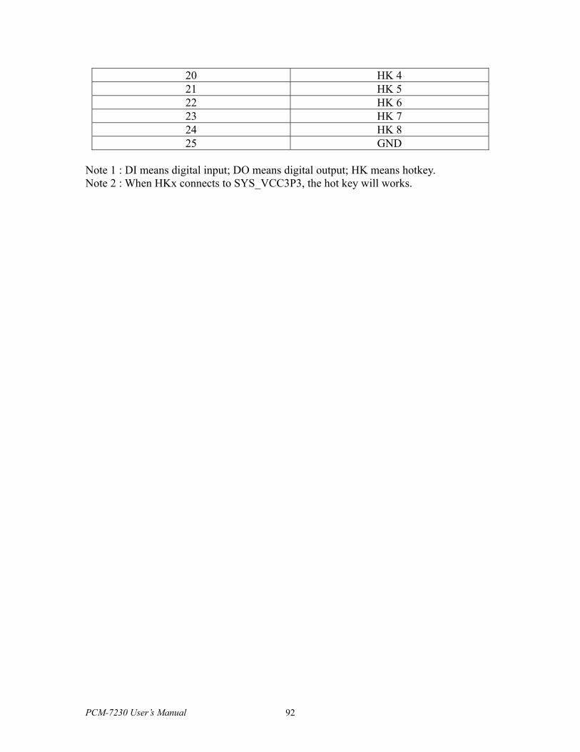
20 HK 4 21 HK 5 22 HK 6 23 HK 7 24 HK 8 25 GND
Note 1 : DI means digital input; DO means digital output; HK means hotkey. Note 2 : When HKx connects to SYS_VCC3P3, the hot key will works.
PCM-7230 User’s Manual 92
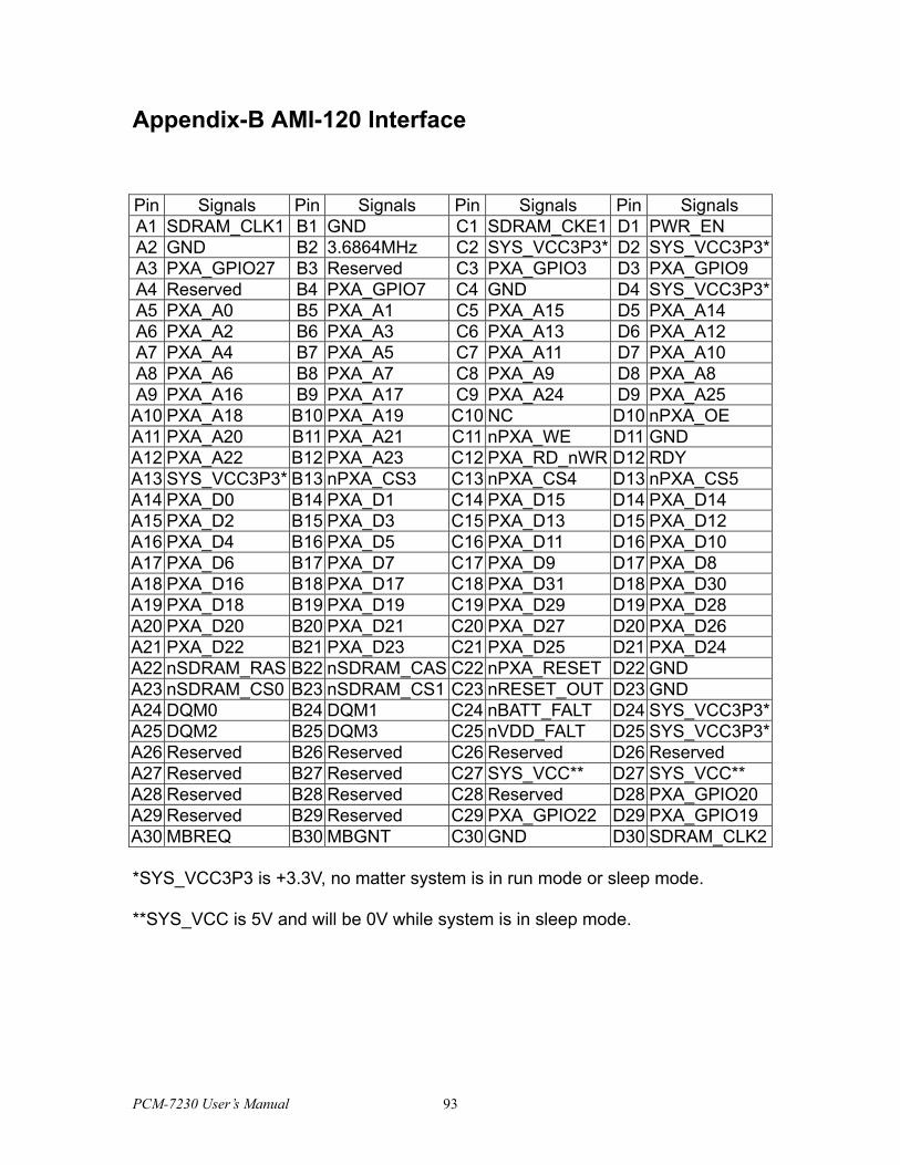
Appendix-B AMI-120 Interface
Pin Signals Pin Signals Pin Signals Pin Signals A1 SDRAM_CLK1 B1 GND C1 SDRAM_CKE1 D1 PWR_EN A2 GND B2 3.6864MHz C2 SYS_VCC3P3* D2 SYS_VCC3P3*A3 PXA_GPIO27 B3 Reserved C3 PXA_GPIO3 D3 PXA_GPIO9 A4 Reserved B4 PXA_GPIO7 C4 GND D4 SYS_VCC3P3*A5 PXA_A0 B5 PXA_A1 C5 PXA_A15 D5 PXA_A14 A6 PXA_A2 B6 PXA_A3 C6 PXA_A13 D6 PXA_A12 A7 PXA_A4 B7 PXA_A5 C7 PXA_A11 D7 PXA_A10 A8 PXA_A6 B8 PXA_A7 C8 PXA_A9 D8 PXA_A8 A9 PXA_A16 B9 PXA_A17 C9 PXA_A24 D9 PXA_A25 A10 PXA_A18 B10 PXA_A19 C10 NC D10 nPXA_OE A11 PXA_A20 B11 PXA_A21 C11 nPXA_WE D11 GND A12 PXA_A22 B12 PXA_A23 C12 PXA_RD_nWR D12 RDY A13 SYS_VCC3P3* B13 nPXA_CS3 C13 nPXA_CS4 D13 nPXA_CS5 A14 PXA_D0 B14 PXA_D1 C14 PXA_D15 D14 PXA_D14 A15 PXA_D2 B15 PXA_D3 C15 PXA_D13 D15 PXA_D12 A16 PXA_D4 B16 PXA_D5 C16 PXA_D11 D16 PXA_D10 A17 PXA_D6 B17 PXA_D7 C17 PXA_D9 D17 PXA_D8 A18 PXA_D16 B18 PXA_D17 C18 PXA_D31 D18 PXA_D30 A19 PXA_D18 B19 PXA_D19 C19 PXA_D29 D19 PXA_D28 A20 PXA_D20 B20 PXA_D21 C20 PXA_D27 D20 PXA_D26 A21 PXA_D22 B21 PXA_D23 C21 PXA_D25 D21 PXA_D24 A22 nSDRAM_RAS B22 nSDRAM_CAS C22 nPXA_RESET D22 GND A23 nSDRAM_CS0 B23 nSDRAM_CS1 C23 nRESET_OUT D23 GND A24 DQM0 B24 DQM1 C24 nBATT_FALT D24 SYS_VCC3P3*A25 DQM2 B25 DQM3 C25 nVDD_FALT D25 SYS_VCC3P3*A26 Reserved B26 Reserved C26 Reserved D26 Reserved A27 Reserved B27 Reserved C27 SYS_VCC** D27 SYS_VCC** A28 Reserved B28 Reserved C28 Reserved D28 PXA_GPIO20 A29 Reserved B29 Reserved C29 PXA_GPIO22 D29 PXA_GPIO19 A30 MBREQ B30 MBGNT C30 GND D30 SDRAM_CLK2
*SYS_VCC3P3 is +3.3V, no matter system is in run mode or sleep mode.
**SYS_VCC is 5V and will be 0V while system is in sleep mode.
PCM-7230 User’s Manual 93
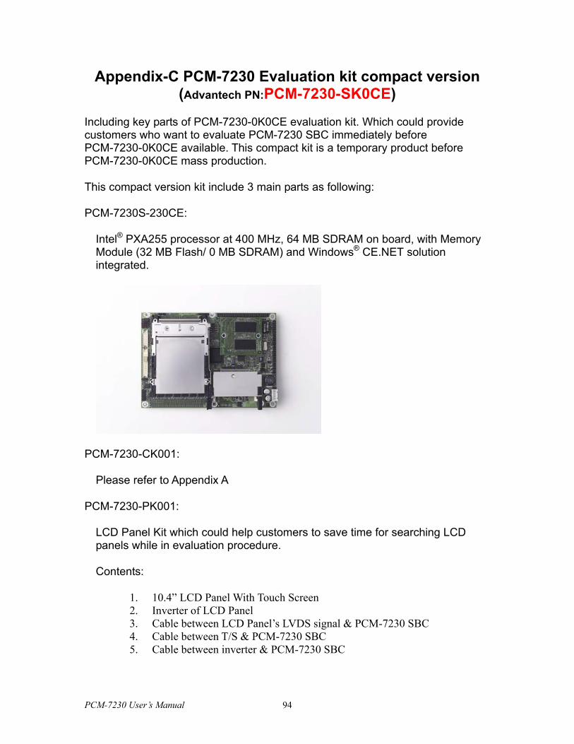
Appendix-C PCM-7230 Evaluation kit compact version (Advantech PN:PCM-7230-SK0CE)
Including key parts of PCM-7230-0K0CE evaluation kit. Which could provide customers who want to evaluate PCM-7230 SBC immediately before PCM-7230-0K0CE available. This compact kit is a temporary product before PCM-7230-0K0CE mass production.
This compact version kit include 3 main parts as following:
PCM-7230S-230CE:
Intel® PXA255 processor at 400 MHz, 64 MB SDRAM on board, with Memory Module (32 MB Flash/ 0 MB SDRAM) and Windows® CE.NET solution integrated.
PCM-7230-CK001:
Please refer to Appendix A
PCM-7230-PK001:
LCD Panel Kit which could help customers to save time for searching LCD panels while in evaluation procedure.
Contents:
1. 10.4” LCD Panel With Touch Screen 2. Inverter of LCD Panel 3. Cable between LCD Panel’s LVDS signal & PCM-7230 SBC 4. Cable between T/S & PCM-7230 SBC 5. Cable between inverter & PCM-7230 SBC
PCM-7230 User’s Manual 94
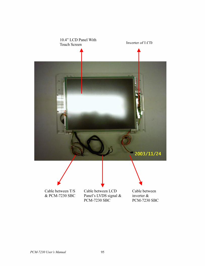
PCM-7230 User’s Manual
Cable between inverter & PCM-7230 SBC
Cable between LCD Panel’s LVDS signal &PCM-7230 SBC
Cable between T/S & PCM-7230 SBC
10.4” LCD Panel WithTouch Screen
95
Inverter of LCD


