8
PCM Series INSTALLATION AND MAINTENANCE MANUAL RELIABLE CHEMICAL FEED PUMPS SINCE 1957

PCM Series INSTALLATION AND MAINTENANCE MANUAL
RELIABLE CHEMICAL FEED PUMPS SINCE 1957
OPERATING REQUIREMENTS
2
SAFETY INSTRUCTIONS
GENERAL SAFETY HAZARDS AND NOTICES
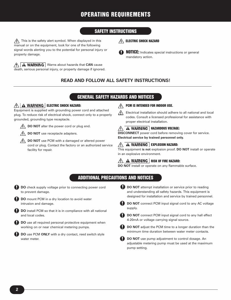
This is the safety alert symbol. When displayed in thismanual or on the equipment, look for one of the followingsignal words alerting you to the potential for personal injury orproperty damage.
Warns about hazards that CAN causedeath, serious personal injury, or property damage if ignored.
NOTICE: Indicates special instructions or generalmandatory action.
READ AND FOLLOW ALL SAFETY INSTRUCTIONS!
ELECTRIC SHOCK HAZARD: Equipment is supplied with grounding power cord and attachedplug. To reduce risk of electrical shock, connect only to a properlygrounded, grounding type receptacle.
DO NOT alter the power cord or plug end.
DO NOT use receptacle adapters.
DO NOT use PCM with a damaged or altered power cord or plug. Contact the factory or an authorized service facility for repair.
PCM IS INTENDED FOR INDOOR USE.
Electrical installation should adhere to all national and local codes. Consult a licensed professional for assistance with proper electrical installation.
HAZARDOUS VOLTAGE:DISCONNECT power cord before removing cover for service.Electrical service by trained personnel only.
EXPLOSION HAZARD: This equipment is not explosion proof. DO NOT install or operatein an explosive environment.
RISK OF FIRE HAZARD:DO NOT install or operate on any flammable surface.
DO check supply voltage prior to connecting power cord to prevent damage.
DO mount PCM in a dry location to avoid water intrusion and damage.
DO install PCM so that it is in compliance with all national and local codes.
DO use all required personal protective equipment when working on or near chemical metering pumps.
DO use PCM ONLY with a dry contact, reed switch style water meter.
ADDITIONAL PRECAUTIONS AND NOTICES
DO NOT attempt installation or service prior to reading and understanding all safety hazards. This equipment is designed for installation and service by trained personnel.
DO NOT connect PCM input signal cord to any AC voltage supply.
DO NOT connect PCM input signal cord to any hall effect 4-20mA or voltage carrying signal source.
DO NOT adjust the PCM time to a longer duration than the minimum time duration between water meter contacts.
DO NOT use pump adjustment to control dosage. An adjustable metering pump must be used at the maximum pump setting.
ELECTRIC SHOCK HAZARD

3
The knob on the PCM providesadjustment of the on-time,required per input signal. Supplyvoltage is transformed to lowvoltage for control circuits and theinput signal for safety duringoperation and installation.
3.75''
Top
4.50''
3.00'' 4.50''
2.00''
Front Side
3.50''
0.1 – 1.0 second setting
0.5 – 5.0 second setting
1.0 – 10.0 second setting
HAZARDOUS VOLTAGE: DISCONNECT power cord before removing cover for service.
The PCM time range is factory set according to the specific model. The time range can be changed to convert a PCM to any of three available timeranges without purchasing another model.
The time range is converted by changing the position of the shunt on the printed circuit board located under the PCM’s cover. To change the time range:
• Unplug the PCM power cord from the input power supply.
• Remove the cover (four screws) and reposition the shunt to correspondwith the desired time range.
• Replace the PCM cover and secure with the four screws.
• Document the PCM conversion, so the correct tables are used during calculations.
PCM Model Time Setting
PCM1 0.1 - 1.0 seconds
PCM5 0.5 - 5.0 seconds
PCM10 1.0 - 10.0 seconds
Microcontroller Timer . . . . . . . . . . . . With triac output
Input Signal Specifications:Type. . . . . . . . . . . . . . . . . . . . . . . Nonvoltage dry contact . . . . . . . . . . . . . . . . . . . . . . . . . . . reed switch meter signal
Reset Time . . . . . . . . . . . . . . . . . Immediate
Minimum Signal Duration. . . . . 10 milliseconds
Input Electrical Specifications:Voltage . . . . . . . . . . . . . . . . . . . . 120VAC 60Hz
No Load Current . . . . . . . . . . . . 0.45 mA AC maximum
Output Electrical:Maximum Device Load . . . . . . . 8 amps resistive at 120VAC
Turndown Ratio . . . . . . . . . . . . . . . . . 10:1
Housing . . . . . . . . . . . . . . . . . . . . . . . . ABS plastic
Shipping Weight . . . . . . . . . . . . . . . . 2 lbs
TECHNICAL SPECIFICATIONS
PCM MODEL CONVERSION
PCM/MP PUMP SIZING GUIDE
P1
P1
P1

INSTALLATION
4
1. Position the PCM within 6 feet of the Stenner fixed outputmetering pump in a protected environment to prevent anypotential water intrusion.
2. Mount the PCM to a suitable surface using adequatefasteners through the mounting holes.
3. Verify the supply voltage to prevent damage to the unit.The use of a GFIC circuit is recommended.
4. Uncoil the input signal cable and remove approximately 2 inches of the outer cable jacket.
5. Strip the ends of the two wires within the cableapproximately one-half inch.
6. Attach the two wires to the contact output water meter or relay switch.
7. Adjust the knob to the desired on-time duration. Refer tothe Section “PCM/MP Pump Sizing Guide” for assistance.
8. Plug the fixed output chemical feed pump power cord intothe PCM’s receptacle.
9. Plug the PCM power cord into a properly installed,grounded, 120VAC receptacle.
The PCM is now set to deliver the desired amount of solution per gallon of water flowing through the meter. Once installed, thesystem may need to be fine-tuned by adjusting the on-time duration and solution concentration according to the application needs.Verify the final PCM settings through analytical testing of the water.
TROUBLESHOOTING
The typical cause of an apparent failure of the PCM is usually:
1. Lack of input supply voltage (120VAC)
Plug the fixed output chemical metering pump directly into the 120VAC receptacle into which the PCM was originallyplugged; this will bypass the PCM. If the pump does not run, the power source or pump is defective. If the metering pumpoperates, proceed to #2.
2. Lack of proper input signal
Plug the metering pump into the PCM and the PCM into the receptacle tested in #1. Remove the PCM input signal cablefrom the water meter or relay and touch the two wires together. The pump should run for the pre-determined on-time andthen stop.
If the metering pump runs, the failure is in the water meter contacts.If the metering pump does not run, the failure is in the PCM.Contact the factory for information on service and repair.
Point ofInjection
PCM PowerCord
Pump Control Module
MeteringPump Power Cord
DryContactWaterMeter
Tank SystemMetering PumpDischarge Line
Refer to themetering pumpmanual forinstallationinstructions.

5
PCM/MP PUMP SIZING GUIDE
PCM Pump Control Module
MP Stenner fixed output metering pump
cpg contacts per gallon (ppg pulse per gallon)
ppm parts per million(mg/l milligramsper liter)
gpm gallons per minute
gpd gallons per day
gps gallons per second
spg seconds per gallon
• Maximum flow rate (of the water system) in gallons per minute (gpm)
• Required dose amount in parts per million (ppm)
• Solution strength in parts per million (ppm)
• Water meter contacts per gallon (cpg or ppg)
• Stenner fixed output metering pump
PRE-SIZING REQUIREMENTSGLOSSARY
STEP 1. AVAILABLE DOSE TIME
The available dose time is the minimum time interval (in seconds) between the water meter contact closures (or input signalsto the PCM) at the maximum system flow rate. (Note: The PCM on-time cannot be longer than the available dose time.)
The available dose time is calculated using two equations:
1a) Divide 60 seconds by the (maximum system flow rate in gpm) to convert into seconds per gallon.
60 seconds ÷ gpm = spg
1b) Divide the seconds per gallon by the water meter contacts per gallon to determine the minimum time interval in seconds between meter contact closures.
spg ÷ cpg = dose time in seconds
STEP 2. DOSE AMOUNT or FEED PUMP OUTPUT
NOTICE: Use a PCM and pump model combination that prevents the PCM time setting (Step 4, next page) frombeing greater than the available dose time (Step 1). The available dose time is the minimum time durationbetween water meter contacts (or input signals to the PCM). DO NOT adjust the PCM to a setting greater than theavailable dose time. Failure to maintain this relationship will result in chemical feed errors. The PCM is designedfor use with fixed output metering pumps. Adjustable pumps MUST be used at maximum output.
Calculate the dose amount (of chemical feed) in gallons per day, based on the maximum system flow rate in gallons per minute. In steps 3 and 4 (next page), you will use this value to determine which feed pump model and PCMcombination is best suited for the application.
Dose amount (pump output) is calculated using two equations. The first equation is the standard feed pump sizing formula:
2a) well pump output OR flow rate in gpm x required dose in ppm x 1440
solution strength in ppm
OR
gpm x ppm x 1440 ÷ solution strength (ppm) = dose amount (feed pump output) in gpd
2b) The pump model to use is based on the dose amount (calculated above) in gallons per day.Convert the gallons per day to gallons per second. (86,400 seconds = 24 hours).
gpd ÷ 86,400 = gpscontinued on page 6

6
PCM/MP PUMP SIZING GUIDE
The PCM setting is the amount of time (in seconds) that the selected pump (step 3) will need to run to deliver the dose amount.
PCM setting is calculated using two equations:
4a) Divide the dose amount (step 2) by the MP pump output (step 3) to determine the PCM setting.
dose amount (gps) ÷ MP pump output (gps) = PCM setting (seconds)
The calculated feed pump run time in seconds (PCM setting) will determine the PCM model. The pump run time must fall within thePCM model’s time range.
STEP 4. ESTABLISH PCM SETTING/FINALIZE PCM MODEL REQUIRED
PCM Model Time Setting
PCM1 .1 - 1 seconds
PCM5 .5 - 5 seconds
PCM10 1 - 10 seconds
4b) The PCM has a 10:1 turndown ratio and to set the PCM knob, convert the PCM setting from seconds into a percentage. Divide the PCM setting (seconds) determined above by the PCM model maximum time range.
PCM setting (seconds) ÷ PCM model max. time range (seconds) = PCM setting (Convert the decimal to a percentage by moving the decimal two places to the right.)
STEP 3. FEED PUMP MODEL
Choose a pump model that closely matches the required dose amount in gallons per second (step 2, previous page).
Model No. gpd gph gpm gps ml/min ml/sec oz/min oz/sec
45mphp2 3 0.1250 0.002 .00004 7.884 0.1314 0.2665 0.0044
45mphp10 10 0.4167 0.007 .00012 26.28 0.4380 0.8880 0.0148
45mphp22 22 0.9167 0.015 .00026 57.82 0.9676 1.9540 0.0326
85mphp5 5 0.2083 0.0035 .00006 13.14 0.2190 0.4440 0.0074
85mphp17 17 0.7083 0.0118 .00020 44.68 0.7446 1.5100 0.0251
85mphp40 40 1.6666 0.0277 .00046 105.12 1.7520 3.5530 0.0592
NOTICE: These figures are approximate estimates and actual output may vary. These values are intended as a guide only. Final testing and field calibration is recommended.
APPROXIMATE OUTPUTS BY STENNER MODEL IN GPD/GPM/GPS/ML/OZ
NOTICE: FINAL PCM SETTINGS must be determined through analytical testing of the water. The procedure andformulas contained herein are intended solely as a guide to be used to assist in the proper application of Stenner’sPCM (Pump Control Module). G. H. Stenner & Co., Inc. makes no guarantee as to the accuracy of the informationcontained herein. User assumes all risk and liability from use of the information contained in this manual.
continued from page 5

7
REFERENCE CHARTS/FORMULAS
COMMON CHEMICAL SOLUTION STRENGTHS
The most popular water meter andthe easiest for calculation purposesis the 1 contact (cpg) or 1 pulse pergallon (ppg) dry contact water meter.
Common Name Chemical Name Strength % Strength ppm
Bleach Sodium Hypochlorite NaOCl 5.25 52,500
Bleach Sodium Hypochlorite NaOCl 6.125 61,250
Bleach Sodium Hypochlorite NaOCl 12.5 125,000
Potassium Potassium Permanganate as 3 30,000
Permanganate KMnO4 dissolved 1/4 lb per Gal
Peroxide Hydrogen Peroxide 8 80,000
Polyphosphate Polyphosphate dissolved 1 lb per 10 Gals 1.2 12,000
• Gallons per day (gpd) to gallons per minute
gpd ÷ 1440 = gpm
• Gallons per day (gpd) to milliliters per minute
gpd x 2.628 = ml/min
• Gallons to milliliters
gals x 3785 = ml
CONVERSION FORMULAS
• Ounces to milliliters
oz x 29.57 = ml
• Milliliters to ounces
ml x .0338 = oz
• Solution Strength % to ppm
% x 10,000 = ppm
Meter Size Max Flow Rate (gpm) Meter cpg/ppg
3/4" 20 10
3/4" 20 5
3/4" 20 2.5
3/4" 20 1
1" 50 1
1" 50 2
1" 50 4
1" 50 5
1 1/2" 100 1
1 1/2" 100 2
1 1/2" 100 4
TYPICAL WATER METER CPG/PPG (Partial List)

3174 DeSalvo RoadJacksonville, Florida [email protected]
www.stenner.comPhone: 904-641-1666US Toll Free: 800-683-2378Fax: 904-642-1012
Hours of Operation (EST):Mon. – Thu. 7 AM – 5 PM Friday 7 AM – Noon
LIMITED WARRANTY AND SERVICE POLICYDamaged or Lost ShipmentsUPS and prepaid truck shipments: Check your order immediately upon arrival. Alldamage must be noted on the delivery receipt. Call Stenner Customer Service at800-683-2378 for all shortages and damages within seven (7) days of receipt.
ReturnsStenner offers a 30-day return policy. Except as otherwise provided, no material willbe accepted for return after 30 days from purchase. To return merchandise at anytime, call Stenner at 800-683-2378 for a Returned Goods Authorization (RGA)number. A 15% re-stocking fee will be applied. Include a copy of your invoice orpacking slip with your return.
Limited WarrantyG. H. Stenner & Co., Inc. will for a period of one (1) year from the date of purchase(proof of purchase required) repair or replace – at our option – all defective parts.G. H. Stenner & Co., Inc. is not responsible for any removal or installation costs. G. H. Stenner & Co., Inc. will incur shipping costs for warranty products shippedfrom our factory in Jacksonville, Florida. Any tampering with major components,chemical damage, faulty wiring, weather conditions, power surges, or productsnot used with reasonable care and maintained in accordance with the instructionswill void the warranty. G. H. Stenner & Co., Inc. limits its liability solely to the costof the original product. We make no other warranty expressed or implied.
DisclaimerThe information contained in this manual is not intended for specific applicationpurposes. G. H. Stenner & Co., Inc. reserves the right to make changes to prices,products and specifications at any time without prior notice.
PCMINST


