Upgrade and Service Smith Meter TM PD Rotary Vane Meters Issue/Rev. 0.2 (3/01) Bulletin MN01039 The Most Trusted Name In Measurement Contents Section 1 — General Information ................................................................................................................ Page 2 Section 2 — Meter Disassembly Instructions ............................................................................................. Page 4 Section 3 — F4 PRIME Upgrade Kit Assembly Instructions ...................................................................... Page 7 Inspection of Parts ..................................................................................................................................... Page 11 Meter Clearance Checks ............................................................................................................................ Page 12 F4-S1/A1-S3/A3 PRIME Upgrade
Transcript
Upgrade and Service
Smith MeterTM PD Rotary Vane Meters
Issue/Rev. 0.2 (3/01) Bulletin MN01039
The Most Trusted Name In Measurement
Contents
Section 1 — General Information ................................................................................................................ Page 2
Section 2 — Meter Disassembly Instructions ............................................................................................. Page 4
Section 3 — F4 PRIME Upgrade Kit Assembly Instructions ...................................................................... Page 7Inspection of Parts ..................................................................................................................................... Page 11Meter Clearance Checks ............................................................................................................................ Page 12
F4-S1/A1-S3/A3PRIME Upgrade
Page 2 • MN01039 Issue/Rev. 0.2 (3/01)
Description
Smith Meter double-case rotary meters are of the positivedisplacement type. The F4 PRIME upgrade uses a similarinner unit as that utilized in a standard F4-S1 PositiveDisplacement meter. Its double-case design eliminatesdistortion of the measuring chamber due to pressure dif-ferential and piping strains. Pipe connections are con-fined to the outer housing which means the measuringelement can be removed by taking off the meter coverassembly and lifting it out. Inspection, maintenance, andservice is greatly simplified through the double-case de-sign.The measuring function is accomplished in a chamber ofprecise volume created by the reciprocating blades, ro-tor, body, and cover. As liquid flows through the meter,the rotor and blades revolve about a fixed cam causingthe blades to reciprocate. The successive movement ofthe blades form a measuring chamber of precise volumebetween two blades, the rotor, the housing, the bottom,and the top covers. A continuous series of these closedchambers is produced as the rotor revolves. Neither bladenor rotor contact the stationary walls of the measuringchamber (Figure 1).
The F4 PRIME upgrade provides a meter variation withpolyketone blades and a super-hardened cam which al-low the meter to operate at higher speeds and increasesthe flow rate from 600 gpm (2,300 L/min) to 800 gpm(3,030 L/min). It provides a direct pulse output which elimi-nates the need for a packing gland and gear train. A self-aligning thrust bearing made of polyketone and surfaced-hardened steel minimizes wear and extends meter lifeimproving meter performance. It makes good sense toupgrade existing Smith Meter F4 PD meters rather thanreplacing them. The F4 PRIME upgrade is less expensiveand offers improved performance and reliability over oldermeters.
Quick Reference
Installation of F4-S1/A1-S3/A3 PRIME Inner Mechanismand Cover Only - See Service Bulletin (PublicationSV01007)Installation/Operation/Wiring of Complete Meter - See In-stallation and Operation Bulletin (Publication MN01037)For F4-S1/A1-S3/A3 PRIME Upgrade Specifications -See Specification Bulletin (Publication SS01097).
Introduction
This manual provides detailed information to upgrade astandard Smith MeterTM Model F4 PD Meter to the F4PRIME upgrade. This affordable upgrade will improve reli-ability, extend the flow range, and allow for direct pulseoutput. See related publications for Specifications, PartsLists, and Installation/Operation information pertaining toyour specific model of meter.
Double-case meter construc-tion features ease of mainte-nance and service. For ex-ample, the measuring unit canbe removed vertically from theouter housing with little spill-age and without disturbingpipe connections. Also, com-plete metering units and partsare interchangeable. As a re-sult, the simple removal anddisassembly steps encourageperiodic preventive mainte-nance inspections.
It is suggested that detailed records be maintained foreach meter installation, such as nameplate data, clear-ances, progressive totalizer readings, meter factor, partsused, and other similar information, that will provide back-ground material for scheduling preventive maintenance.A chart of meter factor versus throughput can be used asthe basis for making an inspection.The time of the first inspection must be based on theoperating conditions imposed by the installation. Flow rate,lubrication properties of the fluid, and the possibilities ofabrasive contaminants are points to consider. Then, atthe time of inspection, the condition of the meter shouldindicate whether the inspection interval can be length-ened or shortened.When ordering parts or inquiring about a unit, be sure toinclude complete model and serial number informationfrom the nameplate.Note: Meters constructed to special specifications (des-ignated by a six-digit serial number) may have clearancesin variance to those shown in this manual. Consult yourrepresentative or the factory for the correct informationregarding your meter.
Figure 1 — Meter Operating Principle
Section 1 — General Information
Issue/Rev. 0.2 (3/01) MN01039 • Page 3
Part No.2 Thickness Part No.2 Thickness515252-1 .0015" 515252-11 .011"515252-2 .002" 515252-12 .012"
515252-3 .003" 515252-13 .013"
515252-4 .004" 515252-14 .014"
515252-5 .005" 515252-15 .015"
515252-6 .006" 515252-16 .016"
515252-7 .007" 515252-17 .017"
515252-8 .008" 515252-18 .018"
515252-9 .009" 515252-19 .019"
515252-10 .010" 515252-20 .020"
Table 1 — Feeler Gauges Sizes
General
To assure adequate inspection kit installation and main-tenance, the step-by-step procedures in this manualshould be carefully followed. To gain a better understand-ing of the meter design and construction, it is suggestedthat the service person review this manual before startingdisassembly.All parts, as they are removed, should be thoroughlycleaned in solvent. Parts that are worn enough to affectoperation or calibration should be replaced. All parts thatare nicked, gouged, or have rough places, should bedressed with a fine file or crocus cloth, as conditionswarrant.
Suggested Tools, Fixtures, and StandardParts
In addition to ordinary hand tools, the following tools andequipment will facilitate work on the meter.
Tools and fixtures:
Suitable lifting equipment.Crocus cloth.Feeler gauges1, leaf-type (as illustrated in Table 1).Wood box (Figure 2) for supporting the rotor assembly.Locktite master gasket.Micrometer1, depth-type - 1”.Spider1 (Figure 2).Alignment tool1, part no. 554229-001
Standard parts (recommended):
Rotor bearings (LPG preferred).Blade rollers and pins.
1 Available through the Smith Parts Operation.Reference Form Number P1205*.
2 Consists of feeler guage soldered to 15" rod. An extension rod (22") and coupling is available as Part No. 515250.* The latest edition is indicated by a two-digit postscript (e.g., .01, .02, etc.).
Figure 2 — Wood Box and Spider
Section 1 — General Information
Page 4 • MN01039 Issue/Rev. 0.2 (3/01)
Disassembly
1. Remove the meter accessories (Figure 3).2. Remove the cover bolts and lift the cover from the
meter (Figure 5) and set aside. To remove the innermechanism, remove the cinch bolts located on themeter between the inlet and outlet flanges (Figure 5).
3. Using the lifting lugs, remove the inner mechanismfrom the housing (Figure 6).
Figure 5 — Remove Cover
Figure 5 — Remove Cinch Bolts
Figure 6 — Lifting Lug on Inner Unit
Figure 3 — Remove Meter Accessories
Figure 9 — Remove Inner Mechanism Cover
Figure 8 — Use Two Covers Bolts as Jacks
Due to sealant used between the inlet port of the innermechanism and meter housing, it may be necessaryto pry them apart (Figure 7).
4. After removal, place the inner mechanism on a suit-able workbench to install the F4 PRIME upgrade kit.To remove the inner mechanism cover, remove all thecover mounting bolts. Make sure to loosen the camshaft cinch bolt. Install two cover bolts in the threadedholes and use them as jacks to remove the cover fromthe housing (Figure 8).
5. Remove the inner mechanism cover (Figure 9).
Figure 7 — Loosen Inner Unit from Meter Housing
Section 2 — Meter Disassembly
Issue/Rev. 0.2 (3/01) MN01039 • Page 5
6. To remove the rotor assembly from the housing, laythe inner mechanism on its side. Make sure to supportthe housing on both sides with blocks to prevent it frommoving or rolling off the workbench.
7. Remove the rotor assembly mounting bolt located atthe bottom center of the inner mechanism housing(Figure 10).
8. Remove the rotor assembly (Figure 11) and place up-side down on the wooden block.
9. Loosen the allen screw on the locating arm and re-move (Figure 12). Make sure to inspect the locatingarm, pin, and key for wear. Note: The pin is located atthe bottom of the inner mechanism housing.
10. To remove the rotor cover, remove the mounting screwand clamps (Figure 13). Lift out the rollers and pins.Note: The rotor cover and rotor are mated parts andshould not be exchanged or replaced individually.
11. To separate the rotor cover and rotor, use a pry bar orscrewdriver in the openings provided in the cover andpry up (to prevent damage to the edge of the rotor).
12. Lift the cover off the rotor; pay attention to the locatingpin and hole to assure proper positioning during reas-sembly (Figure 14).
13. Remove the lower rotor bearing if it is still in place onthe cam and shaft assembly. Lift out the lower blade(Figure 15).
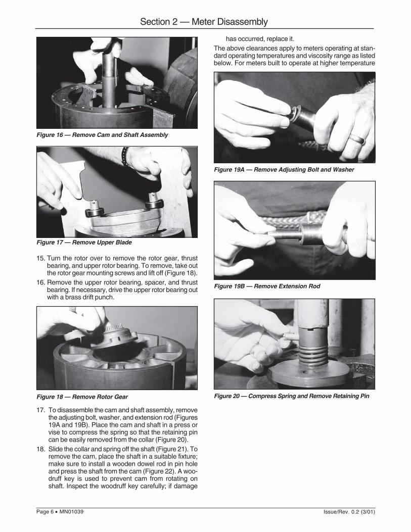
14. Remove the cam and shaft assembly (Figure 16) andthen remove the upper blade (Figure 17).
Figure 12 — Remove Locating Arm
Figure 11 — Remove Rotor Assembly
Figure 10 — Remove Rotor Assembly Mounting Bolt
Figure 14 — Remove Rotor Cover
Figure 13 — Remove Rotor Cover Mounting Screws
Figure 15 — Remove Lower Blade
Section 2 — Meter Disassembly
Page 6 • MN01039 Issue/Rev. 0.2 (3/01)
15. Turn the rotor over to remove the rotor gear, thrustbearing, and upper rotor bearing. To remove, take outthe rotor gear mounting screws and lift off (Figure 18).
16. Remove the upper rotor bearing, spacer, and thrustbearing. If necessary, drive the upper rotor bearing outwith a brass drift punch.
17. To disassemble the cam and shaft assembly, removethe adjusting bolt, washer, and extension rod (Figures19A and 19B). Place the cam and shaft in a press orvise to compress the spring so that the retaining pincan be easily removed from the collar (Figure 20).
18. Slide the collar and spring off the shaft (Figure 21). Toremove the cam, place the shaft in a suitable fixture;make sure to install a wooden dowel rod in pin holeand press the shaft from the cam (Figure 22). A woo-druff key is used to prevent cam from rotating onshaft. Inspect the woodruff key carefully; if damage
Figure 17 — Remove Upper Blade
Figure 16 — Remove Cam and Shaft Assembly
Figure 18 — Remove Rotor Gear
has occurred, replace it.The above clearances apply to meters operating at stan-dard operating temperatures and viscosity range as listedbelow. For meters built to operate at higher temperature
Figure 19A — Remove Adjusting Bolt and Washer
Figure 20 — Compress Spring and Remove Retaining Pin
Figure 19B — Remove Extension Rod
Section 2 — Meter Disassembly
Issue/Rev. 0.2 (3/01) MN01039 • Page 7
Figure 21 — Slide Collar and Spring Off Shaft
Figure 22 — Dowel Rod Keeps Shaft from Falling as it isPressed Out of Cam
Inspection of Parts
All parts that will be reused, should be examined. Specialemphasis should be placed on the rotor slots and theinnermechanism housing measuring section. It is recom-mended that the rotor bearings be replaced, unless theyare new or recently replaced.
Kit Assembly Instructions
The F4 PRIME upgrade kit includes new polyketoneblades, super-hardened cam, rotor gear, thrust bearing,jackshaft and gear, target disc, meter cover, sensor hous-ing, and sensor.To install the F4 PRIME upgrade kit the assembly instruc-tions should be carefully followed.
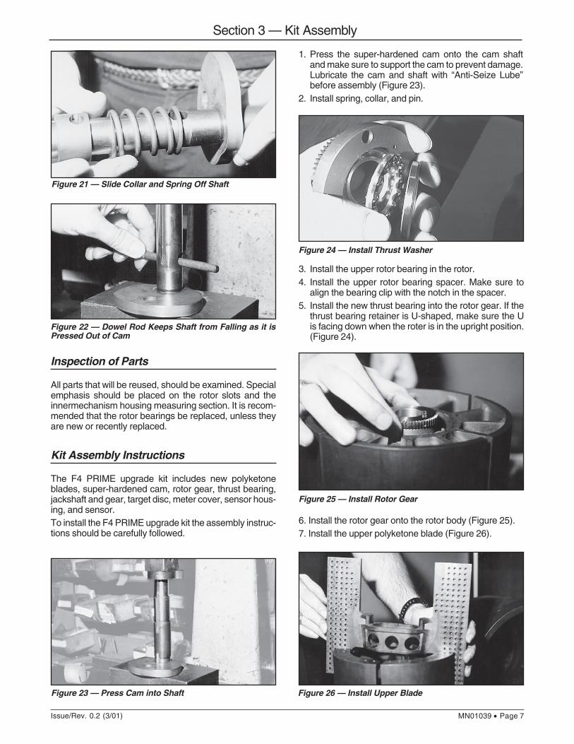
Figure 23 — Press Cam into Shaft
1. Press the super-hardened cam onto the cam shaftand make sure to support the cam to prevent damage.Lubricate the cam and shaft with “Anti-Seize Lube”before assembly (Figure 23).
2. Install spring, collar, and pin.
Figure 24 — Install Thrust Washer
3. Install the upper rotor bearing in the rotor.4. Install the upper rotor bearing spacer. Make sure to
align the bearing clip with the notch in the spacer.5. Install the new thrust bearing into the rotor gear. If the
thrust bearing retainer is U-shaped, make sure the Uis facing down when the roter is in the upright position.(Figure 24).
Figure 25 — Install Rotor Gear
Figure 26 — Install Upper Blade
6. Install the rotor gear onto the rotor body (Figure 25).7. Install the upper polyketone blade (Figure 26).
Section 3 — Kit Assembly
Page 8 • MN01039 Issue/Rev. 0.2 (3/01)
8. Install the cam and shaft assembly. Make sure toalign the surfaced-hardened thrust washer dowel withthe slot in the cam shaft (Figure 27).
9. Install the lower polyketone blade (Figure 28).10. Install the rotor cover (make sure to align the locating
pin and hole). Make sure cover is flush with rotor;install the rollers with pins, clamps, and mountingscrews.
To check blade slot clearance refer to Step C underClearance Checks.
Figure 27 — Install Cam and Shaft Assembly
Figure 28 — Install Lower Blade
11. Install the locating arm and key. Pay special attentionto the direction of installation of the key.Note: There is an upset on one end of key. The keyshould be installed on the shaft, with the upset to-wards the rotor bearing for proper assembly. Tightenallen screw to secure locating arm to rotor shaft.
12. Install rotor assembly into the inner mechanism hous-ing as shown (Figure 29).
13. Reinstall rotor shaft bolt and tighten to secure rotorassembly into housing (refer to disassembly).
14. Install spider check all clearances as specified in theClearance Checks section and refer to the recom-mended clearances in Table 2.
15. Install the jackshaft gear assembly into the innermechanism cover (Figure 30). Make sure the shimwasher is installed under the jackshaft coupler (Fig-ure 30A). Be sure to support jackshaft coupler wheninstalling roll pin to prevent jackshaft or bushing dam-age.
Figure 29 — Install Rotor Assembly
16. Care must be taken when installing the inner mecha-nism cover to assure that the rotor gear and the lowerjackshaft gear are properly meshed. The fit of the innermechanism cover is normally close enough to necessi-tate tapping the cover with a soft hammer to drive it intoplace on the inner unit. At the same time, rotate the rotorby hand from one of the ports. The innermech cover canbe secured with the cover bolts. Once this is com-pleted, the rotor end adjustment must be made.
Figure 30— Install Jackshaft Gear
Figure 30A
Section 3 — Kit Assembly
Issue/Rev. 0.2 (3/01) MN01039 • Page 9
Total end clearance is divided between the top andbottom. To set the rotor adjustment, loosen theadjusting bolt locknut and turn the adjustment boltclockwise. While turning the rotor by hand, slowlylower the rotor assembly until it just begins to bindagainst the base. Mark the position of the adjust-ment bolt to the cover and slowly raise the rotorassembly (turning the adjustment bolt counterclock-wise) unit until it just begins to bind against thecover. Mark the position of the adjustment bolt tothe cover. By means of the adjustment bolt, lowerthe rotor until 1/2 of the clearance is off the top and1/2 is at the bottom. Use the two marks on thecover as reference. (Refer to Rotor Adjustment -Total End Clearance (F) Page 14.)
17. Install the inner mechanism into the meter housing.Make sure inlet and outlet ports are thoroughly cleanedbefore installation. Do not use a scraper or screw-driver on the machined surfaces. Coat both machinedinlet ports with Loctite Master Gasket or other sealingmedium. Lower the inner mechanism into the meterhousing. Apply Master Gasket or other sealing me-dium to the inner mechanism body bolts and tightento draw inner mechanism up to seal the inlet port.
18. Coat the cover O-Ring with petroleum jelly and installO-Ring in groove of outer housing. Install the F4PRIME upgrade cover. Align the cover to the locatingdowel pins in the meter body with the appropriatedowel pinholes in the cover to ensure correct align-ment between the jackshaft coupler and link assem-bly. By placing the cover bolts in the cover aides inthe alignment (Figure 31). You will need to use asmall pry bar to raise the cover to ensure you havecorrect alignment and engagement between thejackshaft coupler and exciter gear link assembly. Ifyou have difficulty making alignment between thejackshaft gear and exciter gear link, remove the sen-sor housing to rotate the gear by hand until appropri-ate alignment is made (Figure 33). Install cover boltsand tighten.
19. Carefully tighten the cover bolts using a cross patterntightening procedure.
20. Reconnect the sensor wiring to the junction box. (Note:Conduit seals must be installed within 18" inches(457 mm) from the junction box (enclosure). Per Chap-ter 5, 1999 National Electrical Handbook.
21. Install the sensor O-Ring to the sensor housing. Lu-bricate the O-Ring with Vaseline or petroleum jellyand install the housing to the meter cover. Install thetwo housing mounting bolts and tighten.
22. Install the sensor (Figure 33).23. When installing the sensor, make sure to align the pin in
the sensor to the slot in the sensor housing. Be sure toalign the dowel pin to the slot in the sensor housing.Install the spring and ring retainer (Figure 34).
Figure 31
Figure 33
Figure 34
Figure 32 — Install O-Ring in Sensor Housing
Section 3 — Kit Assembly
Page 10 • MN01039 Issue/Rev. 0.2 (3/01)
24. Make sure to seat the sensor, and install the tworetaining springs and ring retainer.
25. Install the junction box housing (Figure 35). Be surenot to damage the sensor wire when pushing the wiresup through the bottom of the junction box. Install thesensor-housing nut to the junction box (Figure 36)and tighten by using 1 5/8" and 1 3/8" open-endedwrenches (Figure 37).To prevent moisture from entering the junction box acoating of petroleum jelly should be applied to matingsurfaces.
Figure 35
Figure 35 Figure 36
Figure 37
Section 3 — Kit Assembly
Issue/Rev. 0.2 (3/01) MN01039 • Page 11
Inspection of Parts
All parts that will be reused, should be examined. Special emphasis should be placed on the rotor slots and the innermechanism housing section. It is recommended that the rotor bearings be replaced, unless they are new or recentlyreplaced.
Single Channel
For single-channel meter installation with standard or reverse flow direction, refer to wiring diagram.
Quadrature (Two Channel)
Signal
6-28 Vdc
Logic Common
Bla
ck
Red
Whi
te1
7
3
To AccuLoad II*Typical Connection
AccuLoad IIITypical ConnectionsSee MN06108
*Only one meter position shown for AccuLoad IINote: AccuLoad II must be configured for contact input.
Meter
"A" Signal (Leading)
Logic Common
Bla
ck
Red
Whi
te
"B" Signal (Lagging)4
1
7
3
Yel
low
6-28 Vdc
To AccuLoad II*Typical Connection
AccuLoad IIITypical ConnectionsSee MN06108
*Only one meter position shown for AccuLoad IINote: AccuLoad II must be configured for contact input.
Meter
For quadrature (two-channel) meter installation with standard flow direction, refer to wire connections.For reverse flow direction, reverse the white and yellow wire connections. The yellow wire becomes the “A” pulse signaland the white wire becomes the “B” pulse signal.
Wire Connections
NOTE
Conduit seals shall be installed within 18" inches (457 mm) from the junction box (enclosure).Per Chapter 5, 1999 National Electrical Handbook.
Section 3 — Kit Assembly
Page 12 • MN01039 Issue/Rev. 0.2 (3/01)
MeterModel Rotor to Rotor Adjustment Blade Top End Blade Follower Blade Tip to
No. Block Total End Blade Slot Below Rotor to Cam Radius Housing
and viscosity (designated by a six-digit serial number), consult factory.
Standard Temperature Ranges-20°F to 150°F (-29°C to 65°C).
Standard Viscosity Limit
Clearance Checks
Clearances should be checked with a leaf-type feeler gaugeand compared to the Clearance Guide - Table 2. Anyaverage of clearances that are outside the recommendedclearance in Table 2 should be noted. Certain parts maybe at or over the maximum recommended clearance. Con-sideration should be given to the condition of the part andthe accuracy obtained during meter calibration. Certainmajor parts such as the rotor, cam, and blades need notbe replaced if the meter calibration records show no appre-ciable change in accuracy between provings.The specified clearances are highly desirable and all rea-sonable effort must be made to achieve them. However,due to the number of individual parameters which affectthe final clearance (e.g., dimensional tolerance, geomet-ric conditions, general variability in manufacturing), indi-vidual parts may need dressed with crocus cloth or a finefile.
Blades should move freely in rotor slots and the averageclearance should not exceed the recommended clear-ance, nor shall any single point exceed 50% above the
Figure 38 Figure 39
Less than 2,000 SSU (400 mPa•s).
Caution: When dressing rotor slots, block, or blade, be careful not to remove too much material. The bladesshould have sharp, clean cut edges. Record all measurements in the “as assembled” clearance record.
maximum clearance recommended in Table 2 (Figure 38).Blade Slot Clearance (C): If blade slot clearance doesnot meet recommended clearance, rotor should be re-placed. When installing a new rotor and blade slot clear-ance does not meet minimum recommended clearance,rotor slots may need dressed with a fine file.
Blade Top End Below Rotor Clearance (D)
Special tools required:Depth Micrometer - 1”
Place the depth micrometer on top of the rotor assemblyover the blade. The blade should not project above therotor. If the blade extends above the rotor, it can be dressedwith a sanding block with crocus cloth. If the blade isbeneath the rotor as specified in Table 2, replace theblade (Figure 39).Blade Top End Below Rotor Clearance (D): If bladetop is above rotor, blade top should be dressed with asanding block and crocus cloth. If blade top exceedsbelow-rotor-recommended-clearance, blade should bereplaced.
Section 3 — Kit Assembly
Issue/Rev. 0.2 (3/01) MN01039 • Page 13
Blade Tip to Housing Clearance (A)
Special tools required:Spider (Figure 2)Feeler Gauges, Leaf-Type (Table 1)
With the rotor assembly installed in the inner mechanismhousing, place the spider over the cam shaft and secureinto housing. Turn the rotor assembly until a blade is fullyextended (for each blade paddle) and measure the dis-tance between the blade tip and housing (as shown inFigure 40) using a feeler gauge, leaf type (Table 1). Blademust be forced toward housing to account for the bladefollower.The minimum clearance specified is optimum but localpoints may exceed the maximum clearance recommendedup to 25%.Blade Tip-to-Housing Clearance (A): With rotor assem-bly installed in the inner mechanism housing, install spi-der. Blade tip-to-housing clearance can be checked byrotating the rotor assembly until a blade paddle is fullyextended. Measure between the blade tip and housing. Ifmeasurement does not meet minimum recommendedclearance, dress the blade tip with a sanding block andcrocus cloth until proper clearance is achieved. If clear-ance exceeds recommended clearance, replace the blade.
Rotor to Block Clearance (B)
Special tools required:Spider (Figure 2)Feeler Gauge, Leaf-Type (Table 1)
The clearance between the rotor and block should bemaintained the full length of the rotor.The clearance can be obtained at any point between therotor and block and should meet the recommended clear-ance in Table 2 or meter accuracy may be affected (Fig-ure 41). The minimum specified rotor-to-block clearance isoptimum but the maximum clearance taken may be ex-ceeded in local areas by no more than 25%.
Figure 40
Figure 41
Rotor-to-Block Clearance (B): If rotor-to-block clearancedoes not meet minimum recommended clearance, blockshould be removed and the necessary clearance can beobtained by dressing the back of the block with a fine file.If clearances exceeds recommended clearance, replacethe block.
With the blade in the measuring chamber, the total clear-ance should be maintained between the radius of thecam and one blade roller (follower) only.To measure blade roller (follower) clearance over radiusportion of cam, insert feeler gauge and check throughradius.With the rotor assembly in the inner mechanism hous-ing, the blade follower over cam radius clearance canbe obtained by positioning the blade in the middle ofthe measuring chamber. This will position the bladefollower over the cam radius. Carefully push the bladetoward the measuring chamber and take measurementbetween blade tip and housing. (Precaution: the bladewill tend to rise at one end and can give an incor-rect measurement.) Then, push the blade toward theblock and repeat measurement. The difference betweenthe two measurements will give the blade roller (fol-lower) clearance.With the rotor assembly on the wood box (Figure 2),place magnetic dial indicator on rotor segment and po-sition dial indicator on blade tip. Make sure blade ispositioned over cam radius and move blade back andforth to obtain reading from dial indicator (preferredmethod).Blade Follower-to-Cam Radius Clearance (E): If clear-ance does not meet recommended clearance, replacethe blade.
Section 3 — Kit Assembly
Page 14 • MN01039 Issue/Rev. 0.2 (3/01)
Figure 42
Rotor Adjustment - Total End Clearance (F)
Special Tools required:Feeler Gauge, Leaf-Type (Table 1)
With the rotor assembly installed in the inner mechanismhousing, cover installed, raise the rotor against the coverby turning the adjusting bolt counterclockwise and checktotal end clearance through the inlet port between therotor and base.After assembly, set rotor below cover 1/2 down. Turnadjusting bolt clockwise until rotor bottoms. Mark posi-tion. Turn adjusting bolt counterclockwise to raise rotor,mark position and adjust rotor approximately 1/3 down(Figure 42). 1/2 1/2
Counter clockwise raises totalClockwise lowers total
Raises Lowers
Section 3 — Kit Assembly
Issue/Rev. 0.2 (3/01) MN01039 • Page 15
Bla
de T
opE
nd(D
)B
elow
Rot
orB
lade
Rol
ler
to C
am(E
)R
adiu
sB
lade
to(A
)H
ousi
ng
Rot
orto
(B)
Blo
ck
Met
er &
Mo
del
____
____
____
____
____
____
____
____
Ser
ial N
um
ber
____
____
____
____
____
____
____
____
____
Met
er C
lear
ance
Rec
ord
Item
Dat
eA
s Fo
und
As
Ass
embl
ed
Rot
orA
djus
t-(F
)m
ent E
nd
Bla
deS
lot
(C)
Bla
de T
opE
nd(D
)B
elow
Rot
orB
lade
Rol
ler
to C
am(E
)R
adiu
sB
lade
to(A
)H
ousi
ng
Rot
orto
(B)
Blo
ckItem
Dat
eA
s Fo
und
As
Ass
embl
ed
Rot
orA
djus
t-(F
)m
ent E
nd
Bla
deS
lot
(C)
Dat
eA
s Fo
und
As
Ass
embl
edD
ate
As
Foun
dA
s A
ssem
bled
Dat
eA
s Fo
und
As
Ass
embl
edD
ate
As
Foun
dA
s A
ssem
bled
Page 16 • MN01039 Issue/Rev. 0.2 (3/01)
Bla
de T
opE
nd(D
)B
elow
Rot
orB
lade
Rol
ler
to C
am(E
)R
adiu
sB
lade
to(A
)H
ousi
ng
Rot
orto
(B)
Blo
ck
Met
er &
Mo
del
____
____
____
____
____
____
____
____
Ser
ial N
um
ber
____
____
____
____
____
____
____
____
____
Met
er C
lear
ance
Rec
ord
Item
Dat
eA
s Fo
und
As
Ass
embl
ed
Rot
orA
djus
t-(F
)m
ent E
nd
Bla
deS
lot
(C)
Bla
de T
opE
nd(D
)B
elow
Rot
orB
lade
Rol
ler
to C
am(E
)R
adiu
sB
lade
to(A
)H
ousi
ng
Rot
orto
(B)
Blo
ckItem
Dat
eA
s Fo
und
As
Ass
embl
ed
Rot
orA
djus
t-(F
)m
ent E
nd
Bla
deS
lot
(C)
Dat
eA
s Fo
und
As
Ass
embl
edD
ate
As
Foun
dA
s A
ssem
bled
Dat
eA
s Fo
und
As
Ass
embl
edD
ate
As
Foun
dA
s A
ssem
bled
Issue/Rev. 0.2 (3/01) MN01039 • Page 17
Dat
e:__
____
_P
rodu
ct__
____
____
____
___
Met
er P
rovi
ng R
ecor
d
Flo
w R
ate
Tem
p.
Pre
ssur
eM
eter
Fac
tor
Flo
w R
ate
Tem
p.
Pre
ssur
eM
eter
Fac
tor
Flo
w R
ate
Tem
p.
Pre
ssur
eM
eter
Fac
tor
Dat
e:__
____
_P
rodu
ct__
____
____
____
___
Dat
e:__
____
_P
rodu
ct__
____
____
____
___
Dat
e:__
____
_P
rodu
ct__
____
____
____
___
Flo
w R
ate
Tem
p.
Pre
ssur
eM
eter
Fac
tor
Flo
w R
ate
Tem
p.
Pre
ssur
eM
eter
Fac
tor
Dat
e:__
____
_P
rodu
ct__
____
____
____
___
Dat
e:__
____
_P
rodu
ct__
____
____
____
___
Dat
e:__
____
_P
rodu
ct__
____
____
____
___
Flo
w R
ate
Tem
p.
Pre
ssur
eM
eter
Fac
tor
Flo
w R
ate
Tem
p.
Pre
ssur
eM
eter
Fac
tor
Dat
e:__
____
_P
rodu
ct__
____
____
____
___
Dat
e:__
____
_P
rodu
ct__
____
____
____
___
Flo
w R
ate
Tem
p.
Pre
ssur
eM
eter
Fac
tor
Flo
w R
ate
Tem
p.
Pre
ssur
eM
eter
Fac
tor
Page 18 • MN01039 Issue/Rev. 0.2 (3/01)
Dat
e:__
____
_P
rodu
ct__
____
____
____
___
Met
er P
rovi
ng R
ecor
d
Flo
w R
ate
Tem
p.
Pre
ssur
eM
eter
Fac
tor
Flo
w R
ate
Tem
p.
Pre
ssur
eM
eter
Fac
tor
Flo
w R
ate
Tem
p.
Pre
ssur
eM
eter
Fac
tor
Dat
e:__
____
_P
rodu
ct__
____
____
____
___
Dat
e:__
____
_P
rodu
ct__
____
____
____
___
Dat
e:__
____
_P
rodu
ct__
____
____
____
___
Flo
w R
ate
Tem
p.
Pre
ssur
eM
eter
Fac
tor
Flo
w R
ate
Tem
p.
Pre
ssur
eM
eter
Fac
tor
Dat
e:__
____
_P
rodu
ct__
____
____
____
___
Dat
e:__
____
_P
rodu
ct__
____
____
____
___
Dat
e:__
____
_P
rodu
ct__
____
____
____
___
Flo
w R
ate
Tem
p.
Pre
ssur
eM
eter
Fac
tor
Flo
w R
ate
Tem
p.
Pre
ssur
eM
eter
Fac
tor
Dat
e:__
____
_P
rodu
ct__
____
____
____
___
Dat
e:__
____
_P
rodu
ct__
____
____
____
___
Flo
w R
ate
Tem
p.
Pre
ssur
eM
eter
Fac
tor
Flo
w R
ate
Tem
p.
Pre
ssur
eM
eter
Fac
tor
Revisions included in MN01039 Issue/Rev. 0.2 (3/01):Updated manual to reflect the new cover and sensor design.
The specifications contained herein are subject to change without notice and any user of said specifications should verify from the manufacturer that thespecifications are currently in effect. Otherwise, the manufacturer assumes no responsibility for the use of specifications which may have been changed and areno longer in effect.
Gas Measurement Products:Erie, PA USA Phone 814/898-5000Thetford, England Phone (44) 1842-82-2900Kongsberg, Norway Phone (47) 32/286-700Buenos Aires, Argentina Phone 54 (11) 4312-4736
Integrated Measurement Systems:Corpus Christi, TX USA Phone 361/289-3400Kongsberg, Norway Phone (47) 32/286-700San Juan, Puerto Rico Phone 787/274-3760United Arab Emirates, Dubai Phone 971 +4/331-3646
Liquid Measurement Products:Erie, PA USA Phone 814/898-5000Los Angeles, CA USA Phone 661/702-8660Slough, England Phone (44) 1753-57-1515Ellerbek, Germany Phone (49) 4101-3040Barcelona, Spain Phone (34) 93/201-0989Moscow, Russia Phone (7) 495/564-8705Melbourne, Australia Phone (61) 3/9807-2818
Beijing, China Phone (86) 10/6500-2251Singapore Phone (65) 6861-3011Chennai, India Phone (91) 44/450-4400